JP2023046702A - Production method of glass plate with hole and glass plate - Google Patents
Production method of glass plate with hole and glass plateDownload PDFInfo
- Publication number
- JP2023046702A JP2023046702AJP2021155436AJP2021155436AJP2023046702AJP 2023046702 AJP2023046702 AJP 2023046702AJP 2021155436 AJP2021155436 AJP 2021155436AJP 2021155436 AJP2021155436 AJP 2021155436AJP 2023046702 AJP2023046702 AJP 2023046702A
- Authority
- JP
- Japan
- Prior art keywords
- hole
- opening
- holes
- initial
- glass plate
- Prior art date
- Legal status (The legal status is an assumption and is not a legal conclusion. Google has not performed a legal analysis and makes no representation as to the accuracy of the status listed.)
- Granted
Links
Images


Classifications
- C—CHEMISTRY; METALLURGY
- C03—GLASS; MINERAL OR SLAG WOOL
- C03C—CHEMICAL COMPOSITION OF GLASSES, GLAZES OR VITREOUS ENAMELS; SURFACE TREATMENT OF GLASS; SURFACE TREATMENT OF FIBRES OR FILAMENTS MADE FROM GLASS, MINERALS OR SLAGS; JOINING GLASS TO GLASS OR OTHER MATERIALS
- C03C15/00—Surface treatment of glass, not in the form of fibres or filaments, by etching
- C—CHEMISTRY; METALLURGY
- C03—GLASS; MINERAL OR SLAG WOOL
- C03B—MANUFACTURE, SHAPING, OR SUPPLEMENTARY PROCESSES
- C03B33/00—Severing cooled glass
- C03B33/08—Severing cooled glass by fusing, i.e. by melting through the glass
- C03B33/082—Severing cooled glass by fusing, i.e. by melting through the glass using a focussed radiation beam, e.g. laser
- C—CHEMISTRY; METALLURGY
- C03—GLASS; MINERAL OR SLAG WOOL
- C03C—CHEMICAL COMPOSITION OF GLASSES, GLAZES OR VITREOUS ENAMELS; SURFACE TREATMENT OF GLASS; SURFACE TREATMENT OF FIBRES OR FILAMENTS MADE FROM GLASS, MINERALS OR SLAGS; JOINING GLASS TO GLASS OR OTHER MATERIALS
- C03C23/00—Other surface treatment of glass not in the form of fibres or filaments
- C03C23/0005—Other surface treatment of glass not in the form of fibres or filaments by irradiation
- C03C23/002—Other surface treatment of glass not in the form of fibres or filaments by irradiation by ultraviolet light
- C—CHEMISTRY; METALLURGY
- C03—GLASS; MINERAL OR SLAG WOOL
- C03C—CHEMICAL COMPOSITION OF GLASSES, GLAZES OR VITREOUS ENAMELS; SURFACE TREATMENT OF GLASS; SURFACE TREATMENT OF FIBRES OR FILAMENTS MADE FROM GLASS, MINERALS OR SLAGS; JOINING GLASS TO GLASS OR OTHER MATERIALS
- C03C23/00—Other surface treatment of glass not in the form of fibres or filaments
- C03C23/0005—Other surface treatment of glass not in the form of fibres or filaments by irradiation
- C03C23/0025—Other surface treatment of glass not in the form of fibres or filaments by irradiation by a laser beam
Landscapes
- Chemical & Material Sciences (AREA)
- Materials Engineering (AREA)
- Engineering & Computer Science (AREA)
- Organic Chemistry (AREA)
- Chemical Kinetics & Catalysis (AREA)
- Geochemistry & Mineralogy (AREA)
- General Chemical & Material Sciences (AREA)
- Life Sciences & Earth Sciences (AREA)
- Health & Medical Sciences (AREA)
- Toxicology (AREA)
- Physics & Mathematics (AREA)
- Optics & Photonics (AREA)
- Surface Treatment Of Glass (AREA)
- Laser Beam Processing (AREA)
- Re-Forming, After-Treatment, Cutting And Transporting Of Glass Products (AREA)
Abstract
Description
Translated fromJapanese本発明は、孔を有するガラス板の製造方法およびガラス板に関する。 The present invention relates to a method for manufacturing a glass plate having holes and the glass plate.
例えば貫通孔のような孔を有するガラス板は、ガラスインターポーザなど、多くの用途にニーズがある。 Glass sheets with holes, such as through holes, are in need for many applications, such as glass interposers.
そのようなガラス板は、例えば、ガラス基材の一方の表面にレーザを照射して孔を形成した後、ガラス基材を湿式エッチング処理して孔の形状を整えることにより製造される。 Such a glass plate is manufactured, for example, by irradiating one surface of a glass substrate with a laser to form holes, and then subjecting the glass substrate to a wet etching treatment to shape the holes.
一般に、前述のガラス基材の湿式エッチング処理には、フッ酸溶液が使用される。 In general, a hydrofluoric acid solution is used for the wet etching treatment of the glass substrate described above.
しかしながら、フッ酸溶液を使用して孔のエッチング処理を実施した場合、しばしば、孔の形状が所望の形状からずれてしまい、高精度で所望の形状の孔を形成することが難しいことが知られている。 However, it is known that when a hydrofluoric acid solution is used to etch holes, the shape of the holes often deviates from the desired shape, making it difficult to form holes of the desired shape with high precision. ing.
なお、特許文献1-3には、アルカリ溶液を使用して、ガラス基材の湿式エッチングを実施することが提案されている。
これらの文献では、まずガラス基材にレーザを照射して、改質部が形成される。その後、ガラス基材に対してアルカリ溶液によるエッチング処理を実施して、改質部に孔が形成される。 In these documents, a glass substrate is first irradiated with a laser to form a modified portion. Thereafter, the glass substrate is etched with an alkaline solution to form holes in the modified portion.
しかしながら、本願発明者らの経験では、そのような方法で孔を形成した場合、孔の開口部の形状が所望の形状からずれ、真円に近い開口部が得られないことが認められている。 However, in the experience of the inventors of the present application, it has been recognized that when a hole is formed by such a method, the shape of the opening of the hole deviates from the desired shape, and an opening close to a perfect circle cannot be obtained. .
従って、特許文献1-3に記載の方法を採用しても、高精度に制御された孔を形成することは難しい。 Therefore, even if the methods described in
本発明は、このような背景に鑑みなされたものであり、本発明では、より所望の形状に近い孔を有するガラス板を製造する方法を提供することを目的とする。また、本発明では、より所望の形状に近い孔を有するガラス板を提供することを目的とする。 The present invention has been made in view of such a background, and an object of the present invention is to provide a method of manufacturing a glass plate having holes having a shape closer to a desired shape. Another object of the present invention is to provide a glass plate having holes having a shape closer to a desired shape.
本発明では、孔を有するガラス板の製造方法であって、
(1)相互に対向する第1の表面および第2の表面を有するガラス基材の前記第1の表面にレーザを照射して、前記第1の表面に第1の初期開口を有する1または2以上の初期孔を形成する工程であって、
前記初期孔は、初期貫通孔または初期非貫通孔であり、
前記第1の初期開口は、最大寸法φ1S(μm)が5μm以上であり、
各初期孔において、該初期孔の深さをd1(μm)としたとき、前記初期孔のアスペクト比(d1/φ1S)は、15以上である、工程と、
(2)前記ガラス基材をアルカリ溶液でエッチング処理して、前記初期孔から処理孔を形成する工程と、
を有し、
各処理孔は、前記第1の表面に第1の開口を有し、
各第1の開口は、該第1の開口の外接円の直径と内接円の直径の平均として定められる直径φ1(μm)と、真円度P1(μm)とを有し、各貫通孔における比P1/φ1が10%以下である、製造方法が提供される。In the present invention, there is provided a method for manufacturing a glass plate having holes,
(1) 1 or 2 having a first initial opening on the first surface by irradiating the first surface of a glass substrate having a first surface and a second surface facing each other with a laser; The step of forming the initial hole as described above,
The initial hole is an initial through hole or an initial non-through hole,
The first initial opening has a maximum dimension φ1S (μm) of 5 μm or more,
each initial hole has an aspect ratio (d1 /φ1S ) of 15 or more, where d1 (μm) is the depth of the initial hole;
(2) etching the glass substrate with an alkaline solution to form treated holes from the initial holes;
has
each processing hole having a first opening in the first surface;
Each first opening has a diameter φ1 (μm) defined as the average of the diameter of the circumscribed circle and the diameter of the inscribed circle of the first opening, and the circularity P1 (μm). A manufacturing method is provided in which the ratio P1 /φ1 in the through holes is 10% or less.
また本発明では、
相互に対向する第1の表面および第2の表面を有し、前記第1の表面から前記第2の表面まで貫通する複数の貫通孔を有するガラス板であって、
各貫通孔は、前記第1の表面に第1の開口を有し、前記第2の表面に第2の開口を有し、前記第1の開口と前記第2の開口のうち、大きい方を特定開口と称し、
各特定開口は、該特定開口の外接円の直径と内接円の直径の平均として求められる直径φT(μm)と、真円度PT(μm)とを有し、各貫通孔における比PT/φTが10%以下であり、
各貫通孔における前記特定開口の直径φTの平均値をφTave(μm)とし、直径φTの標準偏差をσ(μm)としたとき、3σ/φTaveは、0.1以下であり、
前記貫通孔からランダムに選定された5個の貫通孔を選択貫通孔と称し、該選択貫通孔の断面におけるそれぞれの狭窄部の最小寸法をφN(μm)としたとき、それぞれの選択貫通孔において、φN/φTは、0.5以上である、ガラス板が提供される。Moreover, in the present invention,
A glass plate having a first surface and a second surface facing each other and having a plurality of through holes penetrating from the first surface to the second surface,
Each through-hole has a first opening on the first surface and a second opening on the second surface, the larger of the first opening and the second opening being Called a specific aperture,
Each specific opening has a diameter φT (μm) obtained by averaging the diameter of the circumscribed circle and the diameter of the inscribed circle of the specific opening, and the circularityPT (μm). PT /φT is 10% or less,
3σ/φTave is 0.1 or less, whereφTave (μm) is the average value of the diameterφT of the specific opening in each through-hole, and σ (μm) is the standard deviation of the diameterφT ,
Five through-holes randomly selected from the through-holes are referred to asselected through-holes. A glass plate is provided in which φN /φT is 0.5 or more.
本発明では、より所望の形状に近い孔を有するガラス板を製造する方法を提供することができる。また、本発明では、より所望の形状に近い孔を有するガラス板を提供することができる。 The present invention can provide a method for manufacturing a glass plate having holes having a shape closer to a desired shape. Moreover, the present invention can provide a glass plate having holes having a shape closer to a desired shape.
以下、図面を参照して、本発明の一実施形態について説明する。 An embodiment of the present invention will be described below with reference to the drawings.
なお、本願では、エッチング処理前の被加工ガラスを「ガラス基材」と称し、エッチング処理後の被加工ガラスを「ガラス板」と称し、一応、両者を区別する。この定義によれば、「ガラス基材」とは、レーザ照射前の孔を有しない被加工ガラス、およびレーザ照射により初期孔が形成された被加工ガラスを意味する。一方、「ガラス板」とは、エッチング処理により形状が整えられた孔を有する「ガラス基材」を意味する。ただし、これらの区別は、便宜的なものであり、明細書の読みやすさの観点から、エッチング処理後の「ガラス板」が「ガラス基材」と称される場合もある。 In the present application, the glass to be processed before etching is referred to as a "glass substrate", and the glass to be processed after etching is referred to as a "glass plate" to distinguish between the two. According to this definition, "glass substrate" means glass to be processed that does not have pores before laser irradiation, and glass to be processed that has initial pores formed by laser irradiation. On the other hand, a "glass plate" means a "glass substrate" having holes shaped by etching. However, these distinctions are for convenience, and from the viewpoint of readability of the specification, the "glass plate" after the etching treatment may be referred to as the "glass base material".
前述のように、孔を有するガラス板の製造方法において、フッ酸による湿式エッチング処理を実施した際に、しばしば、所望の形状の孔が得られないという問題が生じている。 As described above, in the method of manufacturing a glass plate having holes, there often arises a problem that holes of a desired shape cannot be obtained when wet etching treatment with hydrofluoric acid is performed.
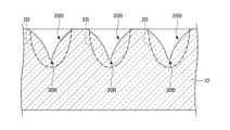
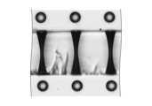
図1には、従来の方法で形成された貫通孔の断面の形状を模式的に示す。図1において、破線は、理想的な貫通孔のプロファイルである。 FIG. 1 schematically shows the cross-sectional shape of a through-hole formed by a conventional method. In FIG. 1, the dashed line is the ideal through-hole profile.
図1に示すように、従来の方法でガラス板10に形成された貫通孔20Aは、略砂時計形の断面形状を有する。すなわち、貫通孔20Aは、理想的な貫通孔のプロファイル2Aに比べて、内部に、直径がより小さい「狭窄部」30Aを有する。 As shown in FIG. 1, through
また、図2には、従来の方法で形成された非貫通孔の断面の形状を模式的に示す。図2において、破線は、理想的な貫通孔のプロファイルである。 Moreover, FIG. 2 schematically shows the cross-sectional shape of a non-through hole formed by a conventional method. In FIG. 2, the dashed line is the ideal through-hole profile.
図2に示すように、従来の方法でガラス板10に形成された非貫通孔20Bは、略逆三角形状の断面を有する。すなわち、非貫通孔20Bは、理想的な非貫通孔のプロファイル2Bに比べて、最深部の直径が十分に広がっておらず、尖った「頂点」30Bを有する。 As shown in FIG. 2, the
このように、エッチング処理後の貫通孔20Aおよび非貫通孔20Bの形状が、所望の形状からずれる場合がしばしば認められている。 As described above, it is often recognized that the shapes of the through
本願発明者らは、このように貫通孔20Aおよび非貫通孔20Bが所望の形状通りに形成されないのは、湿式エッチング工程において、フッ酸溶液が使用されているためであると考察している。 The inventors consider that the reason why the through
すなわち、フッ酸溶液は、ガラス基材に対するエッチング速度が比較的大きい。このため、フッ酸溶液でのエッチング中に、孔内に残渣(不溶性のエッチング生成物)が形成されると、この残渣が孔内から除去されるよりも前に、他の箇所がエッチングされる。このように残渣が局部的に以降の孔のエッチングの進行を妨げる結果、貫通孔20Aの場合は狭窄部30A、非貫通孔20Bの場合は頂点30Bが形成されると考えられる。 That is, the hydrofluoric acid solution has a relatively high etching rate with respect to the glass substrate. Therefore, if a residue (insoluble etching product) is formed in the hole during etching with a hydrofluoric acid solution, other portions are etched before the residue is removed from the hole. . As a result of the residue locally hindering the subsequent etching of the hole, the
特に、貫通孔20Aおよび非貫通孔20Bのアスペクト比が高い場合、このような影響はより顕著になると予想される。 In particular, when the through
このように、従来の方法では、ガラス基材に高精度に制御された孔を形成することは難しいという問題がある。 As described above, the conventional method has the problem that it is difficult to form highly precisely controlled holes in the glass substrate.
なお、このような問題に対する一対処法として、エッチング処理に使用されるフッ酸の濃度を低下させることが考えられる。 As a countermeasure against such problems, it is conceivable to reduce the concentration of hydrofluoric acid used in the etching process.
しかしながら、低濃度のフッ酸溶液では、フッ酸の消耗が激しく、比較的短時間でエッチング機能が低下してしまうという問題がある。従って、そのような対処法は、孔付きガラス板の工業的な生産には適さない。 However, a low-concentration hydrofluoric acid solution has the problem that the hydrofluoric acid is rapidly consumed and the etching function deteriorates in a relatively short period of time. Such a solution is therefore not suitable for the industrial production of perforated glass sheets.
また、特許文献1-3には、アルカリ溶液を使用して、レーザ改質部をエッチング処理する方法が記載されている。 Further,
しかしながら、本願発明者らによれば、特許文献1-3に記載の方法では、最終的に形成される孔の開口部の形状が所望の寸法からずれ、真円に近い開口部が得られないことが認められている。従って、特許文献1-3に記載の方法を採用した場合も、高精度に制御された孔を形成することは難しい。 However, according to the inventors of the present application, in the methods described in
なお、特許文献1-3に記載の方法において、エッチング処理後の孔に所望の形状の開口が得られない理由として、次のことが考えられる。 In addition, in the methods described in
特許文献1-3では、まず、ガラス基材に対するレーザ照射により、深さ方向に延在するレーザ改質部が形成される。次に、改質部を有するガラス基材をエッチング処理することにより、レーザ改質部が選択的にエッチング処理され、孔が形成される。 In
ここで、レーザ改質部を基点として所望の有径の孔を形成するためには、エッチング溶液に触れたレーザ改質部(最初は、ガラス基材の表面のみ)を選択的に除去して、除去部分を延伸方向および半径方向に「拡張」していく必要がある。 Here, in order to form a hole having a desired diameter with the laser-modified portion as a starting point, the laser-modified portion (initially, only the surface of the glass substrate) in contact with the etching solution is selectively removed. , it is necessary to "extend" the removed portion in the direction of extension and in the radial direction.
しかしながら、そのような「拡張」の際に、特に孔の半径方向において、必ずしもガラス基材が等方的に除去されるとは限られない。従って、そのような方法では、最終的に得られる孔において、開口部の形状が真円からずれてしまうと考えられる。 However, during such "expansion", the glass substrate is not always removed isotropically, especially in the radial direction of the holes. Therefore, in such a method, it is considered that the shape of the opening of the finally obtained hole deviates from a perfect circle.
これに対して本発明の一実施形態では、孔を有するガラス板の製造方法であって、
(1)相互に対向する第1の表面および第2の表面を有するガラス基材の前記第1の表面にレーザを照射して、前記第1の表面に第1の初期開口を有する1または2以上の初期孔を形成する工程であって、
前記初期孔は、初期貫通孔または初期非貫通孔であり、
前記第1の初期開口は、最大寸法φ1S(μm)が5μm以上であり、
各初期孔において、該初期孔の深さをd1(μm)としたとき、前記初期孔のアスペクト比(d1/φ1S)は、15以上である、工程と、
(2)前記ガラス基材をアルカリ溶液でエッチング処理して、前記初期孔から処理孔を形成する工程と、
を有し、
各処理孔は、前記第1の表面に第1の開口を有し、
各第1の開口は、該第1の開口の外接円の直径と内接円の直径の平均として定められる直径φ1(μm)と、真円度P1(μm)とを有し、各貫通孔における比P1/φ1が10%以下である、製造方法が提供される。In contrast, in one embodiment of the present invention, there is provided a method for manufacturing a glass sheet having holes, comprising:
(1) 1 or 2 having a first initial opening on the first surface by irradiating the first surface of a glass substrate having a first surface and a second surface facing each other with a laser; The step of forming the initial hole as described above,
The initial hole is an initial through hole or an initial non-through hole,
The first initial opening has a maximum dimension φ1S (μm) of 5 μm or more,
each initial hole has an aspect ratio (d1 /φ1S ) of 15 or more, where d1 (μm) is the depth of the initial hole;
(2) etching the glass substrate with an alkaline solution to form treated holes from the initial holes;
has
each processing hole having a first opening in the first surface;
Each first opening has a diameter φ1 (μm) defined as the average of the diameter of the circumscribed circle and the diameter of the inscribed circle of the first opening, and the circularity P1 (μm). A manufacturing method is provided in which the ratio P1 /φ1 in the through holes is 10% or less.
本発明の一実施形態では、孔のエッチング処理の際に、アルカリ溶液が使用される。 In one embodiment of the invention, an alkaline solution is used during the hole etching process.
アルカリ溶液は、フッ酸溶液に比べて、エッチング速度が低い。しかしながら、そのような低いエッチング速度で孔のエッチング処理を実施することにより、単位時間当たりの残渣の生成量を低減させることができるとともに、残渣が孔から外部に逸散するための十分な時間を提供することができる。 An alkaline solution has a lower etching rate than a hydrofluoric acid solution. However, by performing the hole etching process at such a low etching rate, it is possible to reduce the amount of residue generated per unit time, and to allow sufficient time for the residue to escape from the hole to the outside. can provide.
従って、本発明の一実施形態では、孔のアスペクト比が高い場合であっても、残渣によってエッチングの進行が妨害されるという問題を有意に抑制することができる。その結果、エッチング処理後に、より所望の形状に近い形状を有する孔を形成することができる。 Therefore, in one embodiment of the present invention, even when the aspect ratio of the holes is high, it is possible to significantly suppress the problem that the progress of etching is hindered by the residue. As a result, holes having a shape closer to the desired shape can be formed after the etching process.
また、本発明の一実施形態では、レーザ照射により、ガラス基材に開口を有する孔が形成され、この孔を出発形状として、孔のエッチング処理が開始される。 Further, in one embodiment of the present invention, a hole having an opening is formed in the glass base material by laser irradiation, and the hole etching process is started using this hole as a starting shape.
この場合、改質部を出発形状としてエッチング処理を始める場合とは異なり、予め開口を有する孔を利用して、エッチングを実施できる。このため、エッチング液が孔内に充填された後、半径方向に沿って、より等方的に孔のエッチングを行うことができる。その結果、より所望の形状に近い開口、および深さ方向プロファイルを有する孔を得ることができる。 In this case, unlike the case where the etching process is started with the modified portion as the starting shape, etching can be performed using holes having openings in advance. Therefore, after the holes are filled with the etchant, the holes can be etched more isotropically along the radial direction. As a result, it is possible to obtain a hole having a more desired shape of the opening and a profile in the depth direction.
以上の効果により、本発明の一実施形態による方法では、開口を含め、より所望の形状に近い孔を有するガラス板を提供することが可能となる。特に、本発明の一実施形態による方法では、高いアスペクト比を有する孔の場合も、より所望の形状に近いプロファイルを得ることができる。 Due to the effects described above, the method according to one embodiment of the present invention can provide a glass plate having holes, including openings, that are closer to a desired shape. In particular, the method according to an embodiment of the present invention allows obtaining a profile closer to the desired shape, even for holes having a high aspect ratio.
なお、本願において、アスペクト比は、通常、(孔の深さ)/(レーザ照射側の表面の開口の直径)により定められる。 In the present application, the aspect ratio is usually determined by (depth of hole)/(diameter of opening on laser irradiation side).
ただし、開口が真円ではない場合、開口の直径の代わりに開口の最大寸法が使用されてもよい。 However, if the opening is not a perfect circle, the maximum dimension of the opening may be used instead of the diameter of the opening.
(本発明の一実施形態によるガラス板の製造方法)
次に、図3~図6を参照して、本発明の一実施形態によるガラス板の製造方法について、より具体的に説明する。(Method for producing a glass plate according to one embodiment of the present invention)
Next, a method for manufacturing a glass plate according to an embodiment of the present invention will be described in more detail with reference to FIGS. 3 to 6. FIG.
図3には、本発明の一実施形態によるガラス板の製造方法のフローの一例を模式的に示す。 FIG. 3 schematically shows an example of the flow of the method for manufacturing a glass plate according to one embodiment of the present invention.
図3に示すように、本発明の一実施形態によるガラス板の製造方法(以下、「第1の方法」と称する)は、
(1)相互に対向する第1の表面および第2の表面を有するガラス基材を準備する工程(S110)と、
(2)ガラス基材の第1の表面にレーザを照射して、第1の表面から第2の表面まで貫通する1または2以上の初期貫通孔を形成する工程(S120)と、
(3)ガラス基材をアルカリ溶液で湿式エッチング処理する工程(S130)と、
を有する。As shown in FIG. 3, a method for manufacturing a glass plate according to an embodiment of the present invention (hereinafter referred to as "first method") comprises:
(1) providing a glass substrate having a first surface and a second surface facing each other (S110);
(2) irradiating the first surface of the glass substrate with a laser to form one or more initial through-holes penetrating from the first surface to the second surface (S120);
(3) a step of wet etching the glass substrate with an alkaline solution (S130);
have
以下、各工程について説明する。 Each step will be described below.
(工程S110)
まず、ガラス基材が準備される。(Step S110)
First, a glass substrate is prepared.
図4には、ガラス基材110の断面を模式的に示す。ガラス基材110は、相互に対向する第1の表面112および第2の表面114を有する。 FIG. 4 schematically shows a cross section of the
ガラス基材110の組成は、ガラスである限り特に限られない。ただし、石英ガラスの場合、フッ酸溶液を用いてエッチング処理を実施しても、あまり残渣が生じない。従って、石英ガラスでは、第1の方法を使用する必要性はあまり高くない。 The composition of the
ガラス基材110は、例えば、ソーダライムガラス、無カルカリガラス、または結晶化ガラスなどであってもよい。
ガラス基材110の寸法は、特に限られない。ただし、比較的厚いガラス基材110の方が、本発明の一実施形態による効果をより実感することができる。ガラス基材110の厚さ(t0)は、例えば、0.1mm以上であってもよい。The dimensions of the
(工程S120)
次に、ガラス基材110の第1の表面112にレーザが照射され、初期貫通孔が形成される。(Step S120)
Next, the
レーザの種類は、ガラス基材110に初期貫通孔が形成される限り、特に限られない。レーザは、例えば、UVレーザであってもよい。 The type of laser is not particularly limited as long as the initial through holes are formed in the
また、レーザの照射条件は、特に限られないが、使用するレーザは、フェムト秒レーザまたはナノ秒レーザのようなパルスレーザであることが好ましい。この場合、一度の走査で多数の初期貫通孔を形成することができる。 Also, the laser irradiation conditions are not particularly limited, but the laser used is preferably a pulse laser such as a femtosecond laser or a nanosecond laser. In this case, a large number of initial through holes can be formed in one scan.
図5には、レーザ照射後のガラス基材110の断面を模式的に示す。 FIG. 5 schematically shows a cross section of the
図5に示すように、レーザ照射により、ガラス基材110に、第1の表面112から第2の表面114にわたって貫通する複数の初期貫通孔120が形成される。なお、図5に示した例では、第1の表面112がレーザの入射面である。 As shown in FIG. 5, a plurality of initial through-
各初期貫通孔120において、第1の表面112における開口を第1の初期開口122と称し、第2の表面114における開口を第2の初期開口124と称する。また、第1の初期開口122の寸法の最大値をφ1Sとし、第2の初期開口124の寸法の最大値をφ2Sとする。For each initial through
通常の場合、第1の初期開口122および第2の初期開口124は、略楕円形(円を含む。以下同じ)であり、従って、第1の初期開口122の最大寸法φ1Sおよび第2の初期開口124の最大寸法φ2Sは、それぞれ、楕円の長軸(または円の直径)の寸法に対応する場合が多いと考えられる。Typically, the first
なお、通常の場合、最大寸法φ1S≧最大寸法φ2Sである。すなわち、初期貫通孔120は、第1の初期開口122から第2の初期開口124に向かって断面寸法が徐々に減少する、略テーパー状の形状を有する場合が多い。In addition, in the normal case, the maximum dimension φ1S ≥ the maximum dimension φ2S . That is, the initial through-
第1の初期開口122の最大寸法φ1Sは、例えば、5μm~30μmの範囲である。同様に、第2の初期開口124の最大寸法φ2Sは、例えば、1μm~10μmの範囲である。The maximum dimension φ1S of the first
また、初期貫通孔120のアスペクト比は、15以上である。 Moreover, the aspect ratio of the initial through-
ここで、初期貫通孔120のアスペクト比は、前述のように、(初期貫通孔120の深さ)/(第1の初期開口122の最大寸法φ1S)で表される。ここで、(初期貫通孔120の深さ)=(ガラス基材110の厚さt0)である。Here, the aspect ratio of the initial through-
ただし、最大寸法φ1S、最大寸法φ2S、およびアスペクト比は、最終的に形成される貫通孔の寸法に応じて変化し得る。However, the maximum dimension φ1S , the maximum dimension φ2S and the aspect ratio may vary depending on the dimensions of the finally formed through-hole.
(工程S130)
次に、初期貫通孔120を有するガラス基材110が湿式エッチング処理される。(Step S130)
Next, the
第1の方法では、湿式エッチング処理は、アルカリ成分を含むエッチング溶液を用いて実施される。 In a first method, the wet etching process is performed using an etching solution containing an alkaline component.
エッチング溶液は、アルカリ成分として、例えば、NaOHおよび/またはKOHを含んでもよい。また、エッチング溶液は、さらに、エチレンジアミン四酢酸(EDTA)のようなキレート剤を含んでもよい。 The etching solution may contain eg NaOH and/or KOH as an alkaline component. Also, the etching solution may further include a chelating agent such as ethylenediaminetetraacetic acid (EDTA).
アルカリ成分の含有量は、特に限られないが、例えば、1M~10Mの範囲である。 The content of the alkali component is not particularly limited, but is, for example, in the range of 1M to 10M.
エッチング処理の温度は、特に限られないが、例えば、50℃~95℃の範囲である。 The etching temperature is not particularly limited, but is in the range of 50°C to 95°C, for example.
使用されるエッチング溶液のエッチング速度は、例えば、0.4μm/分以下である。エッチング溶液のエッチング速度は、0.1μm/分以下であることが好ましい。 The etching rate of the etching solution used is, for example, 0.4 μm/min or less. The etching rate of the etching solution is preferably 0.1 μm/min or less.
本願において、エッチング速度は、(処理前後におけるガラス基材の厚さの減少量)/(処理時間)として求められる。 In the present application, the etching rate is obtained as (amount of decrease in thickness of glass substrate before and after treatment)/(treatment time).
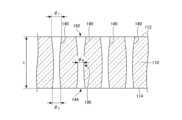
図6には、湿式エッチング処理後のガラス基材110(ガラス板と称されてもよい)の断面を模式的に示す。 FIG. 6 schematically shows a cross section of the glass substrate 110 (which may be referred to as a glass plate) after wet etching treatment.
図6に示すように、湿式エッチング処理により、初期貫通孔120がエッチングされ、処理貫通孔140が形成される。 As shown in FIG. 6, a wet etching process etches the
なお、エッチング処理の際に、ガラス基材110の表面もエッチングされ、ガラス基材110の厚さは、処理前のt0からtに変化する。従って、ガラス基材110の第1の表面112および第2の表面114は、処理後に、それぞれ、新生面に変化する。During the etching process, the surface of the
ただし、本願では、説明の煩雑さを避けるため、ガラス基材110のエッチング処理後の相互に対向する表面を、そのまま、「第1の表面112」および「第2の表面114」と称する。 However, in the present application, in order to avoid complication of the description, the mutually facing surfaces of the
各処理貫通孔140は、第1の表面112の側に第1の開口142を有し、第2の表面114の側に第2の開口144を有する。第1の開口142および第2の開口144は、略楕円形の形状を有してもよい。 Each processing through-
第1の開口142の直径φ1は、例えば、20μm~100μmの範囲である。第2の開口144の直径φ2は、例えば、20μm~100μmの範囲である。The diameter φ1 of the
なお、各第1の開口142の直径φ1は、それぞれの第1の開口142の外接円の直径と内接円の直径の平均として求められる。同様に、各第2の開口144の直径φ2は、それぞれの第2の開口144の外接円の直径と内接円の直径の平均として求められる。The diameter φ1 of each
また、処理貫通孔140のアスペクト比(t/φ1)は、例えば、1以上であってもよい。Also, the aspect ratio (t/φ1 ) of the processing through
ここで、各処理貫通孔140において、第1の開口142の真円度をP1(μm)とする。真円度P1は、以下の(1)式で求められる:
P1=(第1の開口の外接円の直径-第1の開口の内接円の直径)/2 (1)式
また、この真円度P1を用いて、各処理貫通孔140において、比P1/φ1を求めると、この値は、第1の開口142の形状の真円に対する「近さ」を表す。すなわち、比P1/φ1が小さいほど、そのような第1の開口142は、真円に近いと言える。Here, let P1 (μm) be the roundness of the
P1 = (diameter of the circumscribed circle of the first opening - diameter of the inscribed circle of the first opening)/2 Equation (1)
In addition, when the ratio P1 /φ1 is calculated for each processing through-
第1の方法では、形成される処理貫通孔140は、比P1/φ1が10%以下であるという特徴を有する。すなわち、第1の方法では、処理貫通孔140において、真円に近い形状を有する第1の開口142が得られる。In the first method, the processed through-
比P1/φ1は、例えば、5%以下であり、2%以下であることが好ましい。The ratio P1 /φ1 is, for example, 5% or less, preferably 2% or less.
各処理貫通孔140は、延伸方向(ガラス基材110の厚さ方向)に沿って断面寸法が等しいプロファイル、または第1の開口142から第2の開口144に向かって、断面寸法が単調に減少するプロファイルを有することが好ましい。 Each process through-
しかしながら、実際には、図6に示すように、処理貫通孔140は、内部に多少の狭窄部190を有する場合が多い。ただし、そのような場合であっても、各処理貫通孔140において、狭窄部190は、許容範囲内に抑制される。 However, in practice, as shown in FIG. 6, the processing through-
以上の工程により、1または2以上の処理貫通孔140を有するガラス板を製造することができる。 Through the above steps, a glass plate having one or more treated through-
第1の方法では、得られるガラス板において、各処理貫通孔140は、所望の形状に近い形状を有する。 In the first method, each processed through-
例えば、第1の方法により製造されるガラス板において、ランダムに選定された5個の処理貫通孔140を「選択貫通孔」と称し、該「選択貫通孔」の断面におけるそれぞれの狭窄部190の最小寸法をφN(μm)としたとき、それぞれの選択貫通孔において、φN/φ1は、0.5以上であってもよい。特に、φN/φ1は、0.6以上であることが好ましく、0.7以上であることがより好ましい。For example, in the glass plate manufactured by the first method, five randomly selected processing through-
このように、第1の方法では、処理貫通孔140は、内部に形成され得る狭窄部190が有意に抑制されている。従って、第1の方法により製造されたガラス板では、処理貫通孔140に、適切に導電性材料を充填することができる。 Thus, in the first method, the processing through-
また、処理貫通孔140は、第1の開口142の形状が真円により近い。従って、各処理貫通孔140に導電性材料が充填された際に、ガラス板の第1の表面112における導電部の位置精度を有意に高めることができる。 In addition, the shape of the
(本発明の別の実施形態によるガラス板の製造方法)
次に、図7~図9を参照して、本発明の別の実施形態によるガラス板の製造方法について説明する。(Method for producing a glass plate according to another embodiment of the present invention)
Next, a method for manufacturing a glass plate according to another embodiment of the present invention will be described with reference to FIGS. 7 to 9. FIG.
図7には、本発明の別の実施形態によるガラス板の製造方法のフローの一例を模式的に示す。 FIG. 7 schematically shows an example flow of a method for manufacturing a glass plate according to another embodiment of the present invention.
図7に示すように、本発明の別の実施形態によるガラス板の製造方法(以下、「第2の方法」と称する)は、
(1)相互に対向する第1の表面および第2の表面を有するガラス基材を準備する工程(S210)と、
(2)ガラス基材の第1の表面にレーザを照射して、1または2以上の初期非貫通孔を形成する工程(S220)と、
(3)ガラス基材をアルカリ溶液で湿式エッチング処理する工程(S230)と、
を有する。As shown in FIG. 7, a method for manufacturing a glass plate according to another embodiment of the present invention (hereinafter referred to as "second method") comprises:
(1) providing a glass substrate having first and second surfaces facing each other (S210);
(2) irradiating the first surface of the glass substrate with a laser to form one or more initial blind holes (S220);
(3) a step of wet etching the glass substrate with an alkaline solution (S230);
have
なお、第2の方法は、工程S220において形成される孔が初期非貫通孔である点が、前述の第1の方法とは異なっている。換言すれば、第2の方法において、工程S210は、第1の方法における工程S110と同様である。従って、ここでは、工程S220以降について説明する。 The second method differs from the first method described above in that the holes formed in step S220 are initial non-through holes. In other words, in the second method, step S210 is similar to step S110 in the first method. Therefore, steps after step S220 will be described here.
(工程S220)
第2の方法では、ガラス基材の第1の表面にレーザが照射され、初期非貫通孔が形成される。レーザとしては、前述の第1の方法で説明したものを使用することができる。(Step S220)
In a second method, the first surface of the glass substrate is irradiated with a laser to form initial blind holes. As the laser, the one described in the first method can be used.
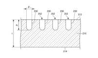
図8には、レーザ照射後のガラス基材210の断面を模式的に示す。 FIG. 8 schematically shows a cross section of the
図8に示すように、ガラス基材210は、相互に対向する第1の表面212および第2の表面214を有する。また、ガラス基材210には、第1の表面212に第1の初期開口232を有する、複数の初期非貫通孔230が形成される。なお、図8において、ガラス基材210の第1の表面212がレーザの入射面である。 As shown in FIG. 8, the
各初期非貫通孔230において、第1の初期開口232の寸法の最大値をφ1Sとする。Let φ1S be the maximum dimension of the first
通常の場合、第1の初期開口232は、略楕円形であり、従って、第1の初期開口232の最大寸法φ1Sは、楕円の長軸(または円の直径)の寸法に対応する場合が多いと考えられる。Typically, the first
なお、通常の場合、初期非貫通孔230は、第1の初期開口232から延伸方向に向かって断面寸法が徐々に減少する、略テーパー状の形状を有する場合が多い。 In addition, in most cases, the initial
第1の初期開口232の最大寸法φ1Sは、例えば、5μm~30μmの範囲である。The maximum dimension φ1S of the first
また、初期非貫通孔230のアスペクト比は、15以上である。ここで、初期非貫通孔230のアスペクト比は、前述のように、(初期非貫通孔230の深さd1)/(第1の初期開口232の最大寸法φ1S)で表される。Also, the aspect ratio of the initial
ただし、これらの値は、最終的に形成される非貫通孔の寸法に応じて定められる。 However, these values are determined according to the dimensions of the non-through holes that are finally formed.
(工程S230)
次に、初期非貫通孔230を有するガラス基材210が湿式エッチング処理される。(Step S230)
Next, the
第2の方法において、エッチング処理の条件は、第1の方法と同様である。例えば、処理溶液は、NaOHおよび/またはKOHのような、アルカリ成分を含む。また、エッチング処理の温度は、例えば、50℃~95℃の範囲であってもよい。 In the second method, the etching conditions are the same as in the first method. For example, the processing solution contains alkaline components, such as NaOH and/or KOH. Also, the temperature of the etching process may be in the range of 50° C. to 95° C., for example.
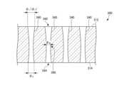
図9には、湿式エッチング処理後のガラス基材210(ガラス板と称されてもよい)の断面を模式的に示す。 FIG. 9 schematically shows a cross section of the glass substrate 210 (which may be referred to as a glass plate) after wet etching.
図9に示すように、湿式エッチング処理により、初期非貫通孔230がエッチングされ、処理非貫通孔250が形成される。 A wet etching process etches the initial
各処理非貫通孔250は、第1の表面212の側に第1の開口252を有する。第1の開口252は、略楕円形の形状を有してもよい。 Each
第1の開口252の直径φ1は、例えば、20μm~100μmの範囲である。前述のように、第1の開口252の直径φ1は、第1の開口252の外接円の直径と内接円の直径の平均として求められる。The diameter φ1 of the
また、処理非貫通孔250の深さをd2(μm)としたとき、アスペクト比、すなわち比d2/φ1は、例えば、1以上であってもよい。Further, when the depth of the
ここで、各処理非貫通孔250において、第1の開口252の真円度をP1(μm)とすると、比P1/φ1は、10%以下である。すなわち、第2の方法では、処理非貫通孔250において、真円に近い形状を有する第1の開口252が得られる。Here, if the circularity of the
比P1/φ1は、例えば、5%以下であり、2%以下であることが好ましい。The ratio P1 /φ1 is, for example, 5% or less, preferably 2% or less.
各処理非貫通孔250は、延伸方向(ガラス基材210の厚さ方向)に沿って断面寸法が等しいプロファイル、または第1の開口252から深さ方向に向かって、断面寸法が単調に減少するプロファイルを有することが好ましい。 Each
以上の工程により、処理非貫通孔250を有するガラス板を製造することができる。 Through the steps described above, a glass plate having
第2の方法においても、第1の方法と同様、所望の形状に近い処理非貫通孔250を有するガラス板を製造することができる。 Also in the second method, similarly to the first method, a glass plate having
(本発明の一実施形態によるガラス板)
次に、図10を参照して、本発明の一実施形態によるガラス板とその特徴について説明する。(Glass plate according to one embodiment of the present invention)
Next, with reference to FIG. 10, a glass plate and its features according to one embodiment of the present invention will be described.
図10には、本発明の一実施形態によるガラス板の断面の一形態を模式的に示す。 FIG. 10 schematically shows one form of a cross section of a glass plate according to one embodiment of the present invention.
本発明の一実施形態によるガラス板300は、石英ガラス以外のガラス、例えば、ソーダライムガラス、無カルカリガラス、または結晶化ガラスなどであってもよい。 The
ガラス板300の寸法は、特に限られない。ガラス板300の厚さは、例えば、0.1mm以上であってもよい。 The dimensions of the
ガラス板300は、相互に対向する第1の表面312および第2の表面314を有する。また、ガラス板300は、第1の表面312から第2の表面314まで貫通する複数の貫通孔340を有する。すなわち、各貫通孔340は、第1の表面312の側に第1の開口342を有し、第2の表面314の側に第2の開口344を有する。
第1の開口342は、直径φ1(μm)を有し、第2の開口344は、直径φ2(μm)を有する。The
前述のように、各貫通孔340の開口の「直径」は、それぞれ、外接円の直径と内接円の直径の平均として求められる。 As described above, the "diameter" of the opening of each through-
図10に示すように、本発明の一実施形態によるガラス板300において、各貫通孔340は、内部に狭窄部390を有してもよい。ただし、ガラス板300では、この狭窄部390は、後述のように、所定の範囲内に抑制される。 As shown in FIG. 10, in the
このようなガラス板300は、例えば、前述の第1の方法により製造され得る。 Such a
ここで、各貫通孔340において、第1の開口342と第2の開口344のうち、より大きな開口を、「特定開口」と称する。さらに、「特定開口」の直径を「φT」で表す。Here, in each through-
なお、各貫通孔340において、ガラス板300の一方の表面(例えば、第1の表面312)にある開口(例えば第1の開口342)が、常に「特定開口」になるとは限られない。すなわち、ある貫通孔340においては第1の開口342が「特定開口」となり、別の貫通孔340においては第2の開口344が「特定開口」となる場合もあり得る。 In addition, in each through-
これは、実際のガラス板の製造過程では、しばしば、初期貫通孔のエッチング処理の際に、片側の開口が優先的にエッチングされることが生じ得るためである。 This is because in the actual manufacturing process of the glass plate, it often happens that the opening on one side is preferentially etched during the etching process of the initial through-hole.
また、一部の貫通孔340においては、第1の開口342と第2の開口344の間で、寸法に実質的な差が認められない場合もあり得る。その場合、第1の表面312および第2の表面314のどちらか一方が、「特定開口」と見なされる。 In some through
ただし、ここでは、簡単のため、いずれの貫通孔340においても、第1の開口342が特定開口であると仮定する。また、また、ガラス板300の第1の表面312がレーザ照射表面であると仮定する。 However, here, for simplicity, it is assumed that the
本発明の一実施形態によるガラス板300において、各貫通孔340の特定開口、すなわち第1の開口342の真円度をPT(μm)とすると、各貫通孔340における比PT/φTは、10%以下である。In the
前述の(1)式のように、特定開口の真円度PTは、以下の(2)式で求められる:
PT=(特定開口の外接円の直径-特定開口の内接円の直径)/2 (2)式
前述のように、比PT/φTは、特定開口の形状の真円に対する「近さ」を表す。すなわち、比PT/φTが小さいほど、そのような特定開口は、真円に近いと言える。従って、比PT/φTの平均が10%以下であるガラス板300は、より真円に近い特定開口を有する。As in Equation (1) above, the roundness PT of a specific aperture is obtained by Equation (2) below:
PT = (diameter of circumscribed circle of specific opening - diameter of inscribed circle of specific opening)/2 Equation (2)
As mentioned above, the ratio PT /φT represents the "closeness" of the shape of a particular aperture to a perfect circle. That is, it can be said that such a specific aperture is closer to a perfect circle as the ratio PT /φT is smaller. Therefore, the
比PT/φTは、例えば、5%以下であり、2%以下であることが好ましい。The ratio PT /φT is, for example, 5% or less, preferably 2% or less.
また、ガラス板300において、各貫通孔340における特定開口の直径φTの平均値をφTave(μm)とし、直径φTの標準偏差をσ(μm)としたとき、3σ/φTaveは、0.1以下である。Further, in the
これは、ガラス板300では、特定開口の直径φTのばらつきが少ないことを意味する。従って、ガラス板300では、各貫通孔340が、より所望の形状に近い特定開口を有すると言える。This means that the
さらに、ガラス板300は、貫通孔340からランダムに選定された5個の貫通孔を「選択貫通孔」と称し、該「選択貫通孔」の断面におけるそれぞれの狭窄部390の最小寸法をφN(μm)としたとき、それぞれの選択貫通孔において、φN/φTが0.5以上であるという特徴を有する。特に、φN/φTは、0.6以上であることが好ましく、0.7以上であることがより好ましい。Furthermore, in the
このように、ガラス板300では、狭窄部390が有意に抑制されている。 Thus, in the
以上のような特徴を有するガラス板300では、貫通孔340に、適切に導電性材料を充填することができる。 In the
また、貫通孔340は、特定開口の形状が真円に近く、各貫通孔340に導電性材料が充填された際に、ガラス板300の第1の表面における導電部の位置精度を有意に高めることができる。 Further, the through-
以下、本発明の実施例について説明する。なお、以下の記載において、例1~例3は、実施例であり、例21~例23は、比較例である。 Examples of the present invention will be described below. In the following description, Examples 1 to 3 are examples, and Examples 21 to 23 are comparative examples.
(例1)
前述の第1の方法により、多数の貫通孔を有するガラス板を形成した。(Example 1)
A glass plate having a large number of through holes was formed by the first method described above.
ガラス基材には、厚さが0.5mmの無アルカリガラス(AN100;AGC株式会社製)を使用した。 Alkali-free glass (AN100; manufactured by AGC Co., Ltd.) having a thickness of 0.5 mm was used as the glass substrate.
ガラス基材の第1の表面に吸収材を付けた状態で、ガラス基材の第1の表面からレーザを照射して初期貫通孔を形成した。レーザには、ナノ秒パルスUVレーザを使用した。レーザは、パルスエネルギー20μJで、50ショット照射した後、パルスエネルギー40μJで、1200ショット照射した。その際の繰り返し周波数は10kHzとし、初期貫通孔形成後、吸収材を除去した。 Initial through-holes were formed by irradiating a laser from the first surface of the glass substrate with the absorber attached to the first surface of the glass substrate. A nanosecond pulsed UV laser was used for the laser. After 50 shots of the laser were irradiated with a pulse energy of 20 μJ, 1200 shots were irradiated with a pulse energy of 40 μJ. The repetition frequency at that time was set to 10 kHz, and the absorbing material was removed after the initial formation of the through holes.
各初期貫通孔において、ガラス基材の第1の表面の側に形成された第1の初期開口の最大寸法φ1Sは、約15μmであった。従って、各初期貫通孔のアスペクト比は、約33.3である。In each initial through-hole, the maximum dimension φ1S of the first initial opening formed on the first surface side of the glass substrate was about 15 μm. Therefore, the aspect ratio of each initial through-hole is approximately 33.3.
図11には、形成された初期貫通孔の断面写真の一例を示す。図11から、高いアスペクト比を有する初期貫通孔が形成されていることがわかる。 FIG. 11 shows an example of a cross-sectional photograph of the formed initial through-hole. It can be seen from FIG. 11 that initial through holes having a high aspect ratio are formed.
次に、このガラス基材をエッチング溶液中に浸漬し、エッチング処理を実施した。 Next, this glass substrate was immersed in an etching solution to carry out an etching treatment.
エッチング溶液には、3MのNaOHおよび1.5MのEDTAを含む水溶液を使用した。エッチング溶液の温度は、85℃とし、浸漬時間は、744分とした。 The etching solution used was an aqueous solution containing 3M NaOH and 1.5M EDTA. The temperature of the etching solution was 85° C. and the immersion time was 744 minutes.
処理後にエッチング溶液からガラス基材を取り出し、厚さを測定した。その結果、ガラス基材は46μm薄くなっていることがわかった。従って、適用したエッチング処理の際のエッチング速度は、0.062μm/分である。 After treatment, the glass substrate was removed from the etching solution and the thickness was measured. As a result, it was found that the glass substrate was thinned by 46 μm. The etching rate during the applied etching process is therefore 0.062 μm/min.
エッチング処理後に、多数の貫通孔が形成されたガラス板が形成された。各貫通孔は、ガラス板の第1の表面の側の第1の開口、および第2の表面の側の第2の開口を有する。 After the etching treatment, a glass plate having many through holes was formed. Each through-hole has a first opening on the side of the first surface of the glass sheet and a second opening on the side of the second surface.
(評価)
(第1の開口に関する測定)
形状測定器(VMR-Z6555;Nikon社製)を用いて、得られたガラス板において、各貫通孔のレーザ照射側の開口(すなわち第1の開口)の直径(φ1)、および真円度(P1)を測定した。また得られた結果から、第1の開口の平均(φ1ave)、および(3σ/φ1ave)等を求めた。さらに、各貫通孔における比P1/φ1を求め、その平均、最小値、および最大値を求めた。(evaluation)
(Measurement regarding the first opening)
Using a shape measuring instrument (VMR-Z6555; manufactured by Nikon Corporation), the diameter (φ1 ) of the opening of each through-hole on the laser irradiation side (that is, the first opening) in the obtained glass plate, and the roundness (P1 ) was measured. Also, from the obtained results, the average (φ1ave ), (3σ/φ1ave ), etc. of the first aperture were determined. Furthermore, the ratio P1 /φ1 in each through-hole was determined, and its average, minimum value, and maximum value were determined.
なお、前述のように、第1の開口の直径φ1は、外接円の直径と内接円の直径の平均として求めた。また、真円度P1は、前述の(1)式から求めた。また、σは、標準偏差である。As described above, the diameterφ1 of the first opening was determined as the average of the diameters of the circumscribed circle and the inscribed circle. Further, the circularityP1 was obtained from the above-described formula (1). Also, σ is the standard deviation.
さらに、ガラス板内の選択された5個の貫通孔(選択貫通孔)の断面の光学顕微鏡観察により、それぞれの選択貫通孔における狭窄部の最小寸法(φN)を測定し、その平均(φNave)を求めた。また、各選択貫通孔において、比φN/φ1を求めた。Furthermore, by observing the cross section of five selected through-holes (selected through-holes) in the glass plate with an optical microscope, the minimum dimension (φN ) of the narrowed portion in each selected through-hole was measured, and the average (φNave ) was sought. Also, the ratio φN /φ1 was determined for each selected through-hole.
以下の表1における例1の欄には、測定結果をまとめて示した。 The column of Example 1 in Table 1 below summarizes the measurement results.

(第2の開口に関する測定)
各貫通孔において、前述の(第1の開口に関する測定)と同様の方法により、第2の開口に関する測定を実施した。
(Measurement regarding the second opening)
In each through-hole, the second opening was measured in the same manner as the above (measurement regarding the first opening).
得られた結果から、各貫通孔における特定開口を決定した。また、特定開口に関する各種値を求めた。具体的には、特定開口の直径の平均(φTave)、3σ、(3σ/φTave)の値、ならびに各貫通孔における比PT/φTの平均、最小値、および最大値を求めた。From the results obtained, the specific opening in each through-hole was determined. In addition, various values regarding the specific aperture were obtained. Specifically, the average (φTave ), 3σ, and (3σ/φTave ) values of the diameters of the specific openings, and the average, minimum, and maximum values of the ratio PT /φT in each through-hole were obtained. .
さらに、前述の5個の選択貫通孔において、比φN/φTを求めた。Furthermore, the ratio φN /φT was determined for the five selected through-holes described above.
以下の表2における例1の欄には、測定結果をまとめて示した。 The column of Example 1 in Table 2 below summarizes the measurement results.

図12には、選択貫通孔の顕微鏡写真の一例を示す。
FIG. 12 shows an example of a photomicrograph of selected through-holes.
図12において、上段にはガラス板の第1の表面、中段には選択貫通孔の断面、下段にはガラス板の第2の表面の形態が示されている。 In FIG. 12, the upper part shows the first surface of the glass plate, the middle part shows the cross section of the selected through hole, and the lower part shows the form of the second surface of the glass plate.
図12から、第1の開口および第2の開口は、いずれも、ほぼ真円に近いことがわかった。実際、表2に示す結果においても、PT/φTの平均は、3.0%であり、最大値も、6.2%と低い値を示した。It can be seen from FIG. 12 that both the first opening and the second opening are nearly perfect circles. In fact, even in the results shown in Table 2, the average PT /φT was 3.0%, and the maximum value was also as low as 6.2%.
また、図12から、選択貫通孔の狭窄部は、いずれも、あまり顕著ではないことがわかった。実際、表2に示すように、(φN/φT)は、59%以上となり、大きな値を示した。Also, from FIG. 12, it was found that the narrowed portions of the selected through-holes were not very conspicuous. Actually, as shown in Table 2, (φN /φT ) was 59% or more, showing a large value.
さらに、表2に示すように、3σ/φTaveは、1.7%と低い値を示した。このことから、各貫通孔の間で、特定開口の直径φTのばらつきが小さいことがわかった。Furthermore, as shown in Table 2, 3σ/φTave showed a low value of 1.7%. From this, it was found that the diameter φT of the specific openings varied little among the through-holes.
(例2)
例1と同様の方法により、多数の貫通孔を有するガラス板を形成した。(Example 2)
A glass plate having a large number of through holes was formed by the same method as in Example 1.
ただし、この例2では、ガラス基材として、例1とは異なる、10GHzにおける誘電正接が0.005以下である無アルカリガラスを使用した。また、エッチング溶液への浸漬時間は、166分とした。適用したエッチング処理の際のエッチング速度は、0.343μm/分であった。 However, in Example 2, different from Example 1, non-alkali glass having a dielectric loss tangent of 0.005 or less at 10 GHz was used as the glass substrate. Also, the immersion time in the etching solution was 166 minutes. The etch rate during the applied etching process was 0.343 μm/min.
前述の表1の例2および表2の例2の欄には、形成された各貫通孔の寸法測定結果をまとめて示した。 The columns of Example 2 in Table 1 and Example 2 in Table 2 collectively show the results of dimensional measurement of each formed through-hole.
図13には、エッチング処理前の初期貫通孔の断面写真の一例を示す。図13から、高いアスペクト比の貫通孔が形成されていることがわかる。 FIG. 13 shows an example of a cross-sectional photograph of an initial through-hole before etching. It can be seen from FIG. 13 that through holes with a high aspect ratio are formed.
図14には、選択貫通孔の顕微鏡写真の一例を示す。 FIG. 14 shows an example of a micrograph of selective through-holes.
図14において、上段にはガラス板の第1の表面、中段には選択貫通孔の断面、下段にはガラス板の第2の表面の形態が示されている。 In FIG. 14, the upper part shows the first surface of the glass plate, the middle part shows the cross section of the selected through hole, and the lower part shows the form of the second surface of the glass plate.
図14から、第1の開口および第2の開口は、いずれも、ほぼ真円に近いことがわかった。実際、表2に示す結果においても、PT/φTの平均は、2.7%であり、最大値も、3.2%と低い値を示した。It can be seen from FIG. 14 that both the first opening and the second opening are nearly perfect circles. In fact, even in the results shown in Table 2, the average PT /φT was 2.7%, and the maximum value was also as low as 3.2%.
また、図14から、選択貫通孔の狭窄部は、いずれも、あまり顕著ではないことがわかった。実際、表2に示すように、(φN/φT)は、62%以上となり、大きな値を示した。Also, from FIG. 14, it was found that the narrowed portions of the selected through-holes were not very conspicuous. Actually, as shown in Table 2, (φN /φT ) was 62% or more, showing a large value.
さらに、表2に示すように、3σ/φTaveは、4.6%と低い値を示した。このことから、各貫通孔の間で、特定開口の直径φTのばらつきが小さいことがわかった。Furthermore, as shown in Table 2, 3σ/φTave showed a low value of 4.6%. From this, it was found that the diameter φT of the specific openings varied little among the through-holes.
(例3)
例2と同様の方法により、多数の貫通孔を有するガラス板を形成した。(Example 3)
A glass plate having a large number of through holes was formed in the same manner as in Example 2.
ただし、この例3では、エッチング溶液の温度を65℃とした。また、ガラス基材のエッチング溶液への浸漬時間は、540分とした。適用したエッチング処理の際のエッチング速度は、0.083μm/分であった。 However, in Example 3, the temperature of the etching solution was set to 65°C. Also, the immersion time of the glass substrate in the etching solution was set to 540 minutes. The etching rate during the applied etching process was 0.083 μm/min.
前述の表1の例3および表2の例3の欄には、形成された各貫通孔の寸法測定結果をまとめて示した。 The columns of Example 3 of Table 1 and Example 3 of Table 2 collectively show the dimensional measurement results of the formed through-holes.
図15には、選択貫通孔の顕微鏡写真の一例を示す。 FIG. 15 shows an example of a micrograph of selective through-holes.
図15において、上段にはガラス板の第1の表面、中段には選択貫通孔の断面、下段にはガラス板の第2の表面の形態が示されている。 In FIG. 15, the upper part shows the first surface of the glass plate, the middle part shows the cross section of the selected through hole, and the lower part shows the form of the second surface of the glass plate.
図15から、第1の開口および第2の開口は、いずれも、ほぼ真円に近いことがわかった。実際、表2に示す結果においても、PT/φTの平均は、3.2%で、最大値も、5.7%と低い値を示した。It can be seen from FIG. 15 that both the first opening and the second opening are nearly perfect circles. In fact, even in the results shown in Table 2, the average PT /φT was 3.2%, and the maximum value was also low at 5.7%.
また、図15から、選択貫通孔の狭窄部は、いずれも、あまり顕著ではないことがわかった。実際、表2に示すように、(φN/φT)は、74%以上となり、大きな値を示した。Also, from FIG. 15, it was found that the narrowed portions of the selected through-holes were not very conspicuous. Actually, as shown in Table 2, (φN /φT ) was 74% or more, showing a large value.
さらに、表2に示すように、3σ/φTaveは、3.7%と低い値を示した。このことから、各貫通孔の間で、特定開口の直径φTのばらつきが小さいことがわかった。Furthermore, as shown in Table 2, 3σ/φTave showed a low value of 3.7%. From this, it was found that the diameter φT of the specific openings varied little among the through-holes.
(例21)
例1と同様の方法により、多数の貫通孔を有するガラス板を形成した。(Example 21)
A glass plate having a large number of through holes was formed by the same method as in Example 1.
ただし、この例21では、エッチング溶液として、2.3wt%のフッ酸および6wt%の硝酸を含む水溶液を使用した。また、エッチング溶液の温度は、25℃とした。 However, in Example 21, an aqueous solution containing 2.3 wt % hydrofluoric acid and 6 wt % nitric acid was used as the etching solution. Also, the temperature of the etching solution was set to 25°C.
ガラス基材のエッチング溶液への浸漬時間は、111分とした。適用したエッチング処理の際の平均エッチングは、0.901μm/分であった。 The immersion time of the glass substrate in the etching solution was 111 minutes. The average etch during the applied etch process was 0.901 μm/min.
前述の表1の例21および表2の例21の欄には、形成された各貫通孔の寸法測定結果をまとめて示した。 The columns of Example 21 of Table 1 and Example 21 of Table 2 collectively show the results of dimensional measurement of each formed through-hole.
図16には、選択貫通孔の一部の顕微鏡写真の一例を示す。 FIG. 16 shows an example of a photomicrograph of a part of the selected through-holes.
図16において、上段にはガラス板の第1の表面、中段には選択貫通孔の断面、下段にはガラス板の第2の表面の形態が示されている。 In FIG. 16, the upper part shows the first surface of the glass plate, the middle part shows the cross section of the selected through hole, and the lower part shows the form of the second surface of the glass plate.
図16から、選択貫通孔の内部には、顕著な狭窄部が生じていることがわかった。実際、表2に示すように、(φN/φT)は、35%以下となり、小さな値を示した。From FIG. 16, it was found that a conspicuous narrowed portion was generated inside the selected through-hole. Actually, as shown in Table 2, (φN /φT ) was 35% or less, showing a small value.
さらに、表2に示すように、3σ/φTaveは、7.8%と比較的大きな値を示した。このことから、形成された各貫通孔の間で、特定開口の直径φTのばらつきが大きいことがわかった。Furthermore, as shown in Table 2, 3σ/φTave showed a relatively large value of 7.8%. From this, it was found that the diameter φT of the specific opening varied greatly among the formed through-holes.
(例22)
例21と同様の方法により、多数の貫通孔を有するガラス板を形成した。(Example 22)
A glass plate having a large number of through holes was formed by the same method as in Example 21.
ただし、この例22では、エッチング処理中に、溶液に対して超音波振動を印加した。また、ガラス基材のエッチング溶液への浸漬時間は、94分とした。適用したエッチング処理の際のエッチング速度は、1.043μm/分であった。 However, in Example 22, ultrasonic vibration was applied to the solution during the etching process. Also, the immersion time of the glass substrate in the etching solution was 94 minutes. The etching rate during the applied etching process was 1.043 μm/min.
前述の表1の例22および表2の例22の欄には、形成された各貫通孔の寸法測定結果をまとめて示した。 The columns of Example 22 of Table 1 and Example 22 of Table 2 collectively show the results of dimensional measurement of each formed through-hole.
図17には、選択貫通孔の一部の顕微鏡写真の一例を示す。 FIG. 17 shows an example of a photomicrograph of a part of the selected through-holes.
図17において、上段にはガラス板の第1の表面、中段には選択貫通孔の断面、下段にはガラス板の第2の表面の形態が示されている。 In FIG. 17, the upper part shows the first surface of the glass plate, the middle part shows the cross section of the selected through hole, and the lower part shows the form of the second surface of the glass plate.
図17から、例22では、選択貫通孔の狭窄部は、いずれも、あまり顕著ではないことがわかった。 From FIG. 17, it can be seen that in Example 22, any narrowing of the selected through-holes is not very pronounced.
しかしながら、表2に示すように、3σ/φTaveは、19.2%と大きな値を示した。このことから、例22では、形成された各貫通孔の間で、特定開口の直径φTのばらつきが大きいことがわかった。However, as shown in Table 2, 3σ/φTave showed a large value of 19.2%. From this, it was found that in Example 22, the diameter φT of the specific opening varied greatly among the formed through holes.
(例23)
以下の方法により、多数の貫通孔を有するガラス板を形成した。(Example 23)
A glass plate having a large number of through holes was formed by the following method.
ガラス基材には、厚さが0.3mmの無アルカリガラス(AN100;AGC株式会社製)を使用した。 Alkali-free glass (AN100; manufactured by AGC Co., Ltd.) having a thickness of 0.3 mm was used as the glass substrate.
次に、ガラス基材の第1の表面の側からレーザを照射し、厚さ方向に沿って、第1の表面から第2の表面まで延在する改質部を形成した。レーザには、ピコ秒パルスグリーンレーザを使用した。レーザの照射パワーは、100μJであり、繰り返し周波数は200kHzとし、1ショットで加工を行った。 Next, a laser was irradiated from the first surface side of the glass substrate to form a modified portion extending from the first surface to the second surface along the thickness direction. A picosecond pulsed green laser was used as the laser. The irradiation power of the laser was 100 μJ, the repetition frequency was 200 kHz, and processing was performed by one shot.
次に、このガラス基材をエッチング溶液中に浸漬し、エッチング処理を実施した。 Next, this glass substrate was immersed in an etching solution to carry out an etching treatment.
エッチング溶液には、3MのNaOHおよび1.5MのEDTAを含む水溶液を使用した。エッチング溶液の温度は、85℃とし、浸漬時間は、588分とした。 The etching solution used was an aqueous solution containing 3M NaOH and 1.5M EDTA. The temperature of the etching solution was 85° C. and the immersion time was 588 minutes.
処理後にエッチング溶液からガラス基材を取り出し、厚さを測定した。その結果、ガラス基材は0.04μm薄くなっていることがわかった。従って、適用したエッチング処理の際のエッチング速度は、0.068μm/分である。 After treatment, the glass substrate was removed from the etching solution and the thickness was measured. As a result, it was found that the glass substrate was thinned by 0.04 μm. The etching rate during the applied etching process is therefore 0.068 μm/min.
エッチング処理後に、多数の貫通孔が形成されたガラス板が形成された。各貫通孔は、ガラス板の第1の表面の側の第1の開口、および第2の表面の側の第2の開口を有する。 After the etching treatment, a glass plate having many through holes was formed. Each through-hole has a first opening on the side of the first surface of the glass sheet and a second opening on the side of the second surface.
その後は、例1と同様の方法により、各貫通孔の形状を測定した。 After that, the shape of each through-hole was measured in the same manner as in Example 1.
前述の表1の例23および表2の例23の欄には、形成された各貫通孔の寸法測定結果をまとめて示した。 The columns of Example 23 of Table 1 and Example 23 of Table 2 collectively show the results of dimensional measurement of each formed through-hole.
図18には、選択貫通孔の一部の顕微鏡写真の一例を示す。 FIG. 18 shows an example of a photomicrograph of a part of the selected through-holes.
図18において、上段にはガラス板の第1の表面、中段には選択貫通孔の断面、下段にはガラス板の第2の表面の形態が示されている。 In FIG. 18, the upper part shows the first surface of the glass plate, the middle part shows the cross section of the selected through hole, and the lower part shows the form of the second surface of the glass plate.
図18から、例23では、選択貫通孔の狭窄部は、いずれも、あまり顕著ではないことがわかった。 From FIG. 18, it can be seen that in Example 23, any narrowing of the selected through-holes is not very noticeable.
しかしながら、選択貫通孔において、第1の開口および第2の開口は、いずれも、真円から大きく逸脱した楕円形状であることがわかった。実際、表2に示す結果においても、PT/φTの平均は、7.5%であり、個々の測定値も5.0%から13.7%の範囲の高い値を示した。However, it was found that in the selected through-holes, both the first opening and the second opening had elliptical shapes that greatly deviated from perfect circles. In fact, even in the results shown in Table 2, the average PT /φT was 7.5%, and the individual measured values also showed high values ranging from 5.0% to 13.7%.
このように、例23では、形成された貫通孔において、第1の開口および第2の開口の形状は、真円とはかけ離れていることがわかった。 Thus, in Example 23, it was found that in the formed through-hole, the shapes of the first opening and the second opening were far from perfect circles.
以上の結果から、例1~例3では、例21~例23に比べて、より所望の形状に近い貫通孔を形成できることが確認された。 From the above results, it was confirmed that in Examples 1 to 3, a through hole closer to the desired shape could be formed than in Examples 21 to 23.
2A 理想的な貫通孔のプロファイル
2B 理想的な非貫通孔のプロファイル
10 ガラス板
20A 貫通孔
20B 非貫通孔
30A 狭窄部
30B 頂点
110 ガラス基材
112 第1の表面
114 第2の表面
120 初期貫通孔
122 第1の初期開口
124 第2の初期開口
140 処理貫通孔
142 第1の開口
144 第2の開口
190 狭窄部
210 ガラス基材
212 第1の表面
214 第2の表面
230 初期非貫通孔
232 第1の初期開口
250 処理非貫通孔
252 第1の開口
300 ガラス板
312 第1の表面
314 第2の表面
340 貫通孔
342 第1の開口
344 第2の開口
390 狭窄部2A ideal through
Claims (8)
Translated fromJapanese(1)相互に対向する第1の表面および第2の表面を有するガラス基材の前記第1の表面にレーザを照射して、前記第1の表面に第1の初期開口を有する1または2以上の初期孔を形成する工程であって、
前記初期孔は、初期貫通孔または初期非貫通孔であり、
前記第1の初期開口は、最大寸法φ1S(μm)が5μm以上であり、
各初期孔において、該初期孔の深さをd1(μm)としたとき、前記初期孔のアスペクト比(d1/φ1S)は、15以上である、工程と、
(2)前記ガラス基材をアルカリ溶液でエッチング処理して、前記初期孔から処理孔を形成する工程と、
を有し、
各処理孔は、前記第1の表面に第1の開口を有し、
各第1の開口は、該第1の開口の外接円の直径と内接円の直径の平均として定められる直径φ1(μm)と、真円度P1(μm)とを有し、各貫通孔における比P1/φ1が10%以下である、製造方法。A method for manufacturing a glass plate having holes,
(1) 1 or 2 having a first initial opening on the first surface by irradiating the first surface of a glass substrate having a first surface and a second surface facing each other with a laser; The step of forming the initial hole as described above,
The initial hole is an initial through hole or an initial non-through hole,
The first initial opening has a maximum dimension φ1S (μm) of 5 μm or more,
each initial hole has an aspect ratio (d1 /φ1S ) of 15 or more, where d1 (μm) is the depth of the initial hole;
(2) etching the glass substrate with an alkaline solution to form treated holes from the initial holes;
has
each processing hole having a first opening in the first surface;
Each first opening has a diameter φ1 (μm) defined as the average of the diameter of the circumscribed circle and the diameter of the inscribed circle of the first opening, and the circularity P1 (μm). A manufacturing method, wherein the ratio P1 /φ1 in the through-hole is 10% or less.
前記貫通孔からランダムに選定された5個の貫通孔を選択貫通孔と称し、該選択貫通孔の断面におけるそれぞれの狭窄部の最小寸法をφN(μm)としたとき、それぞれの選択貫通孔において、φN/φ1は、0.5以上である、請求項1乃至6のいずれか一項に記載の製造方法。The processing hole is a through hole,
Five through-holes randomly selected from the through-holes are referred to asselected through-holes. 7. The manufacturing method according to any one of claims 1 to 6, wherein φN /φ1 is 0.5 or more.
各貫通孔は、前記第1の表面に第1の開口を有し、前記第2の表面に第2の開口を有し、前記第1の開口と前記第2の開口のうち、大きい方を特定開口と称し、
各特定開口は、該特定開口の外接円の直径と内接円の直径の平均として求められる直径φT(μm)と、真円度PT(μm)とを有し、各貫通孔における比PT/φTが10%以下であり、
各貫通孔における前記特定開口の直径φTの平均値をφTave(μm)とし、直径φTの標準偏差をσ(μm)としたとき、3σ/φTaveは、0.1以下であり、
前記貫通孔からランダムに選定された5個の貫通孔を選択貫通孔と称し、該選択貫通孔の断面におけるそれぞれの狭窄部の最小寸法をφN(μm)としたとき、それぞれの選択貫通孔において、φN/φTは、0.5以上である、ガラス板。A glass plate having a first surface and a second surface facing each other and having a plurality of through holes penetrating from the first surface to the second surface,
Each through-hole has a first opening on the first surface and a second opening on the second surface, the larger of the first opening and the second opening being Called a specific aperture,
Each specific opening has a diameter φT (μm) obtained by averaging the diameter of the circumscribed circle and the diameter of the inscribed circle of the specific opening, and the circularityPT (μm). PT /φT is 10% or less,
3σ/φTave is 0.1 or less, whereφTave (μm) is the average value of the diameterφT of the specific opening in each through-hole, and σ (μm) is the standard deviation of the diameterφT ,
Five through-holes randomly selected from the through-holes are referred to asselected through-holes. In the glass plate, φN /φT is 0.5 or more.
Priority Applications (4)
| Application Number | Priority Date | Filing Date | Title |
|---|---|---|---|
| JP2021155436AJP7657398B2 (en) | 2021-09-24 | 2021-09-24 | Method for manufacturing a glass plate having a hole and a glass plate |
| US17/931,198US20230095132A1 (en) | 2021-09-24 | 2022-09-12 | Manufacturing method of glass plate having holes, and glass plate |
| TW111134250ATW202337611A (en) | 2021-09-24 | 2022-09-12 | Production method of glass plate with hole and glass plate |
| JP2024213764AJP2025023309A (en) | 2021-09-24 | 2024-12-06 | Glass plate |
Applications Claiming Priority (1)
| Application Number | Priority Date | Filing Date | Title |
|---|---|---|---|
| JP2021155436AJP7657398B2 (en) | 2021-09-24 | 2021-09-24 | Method for manufacturing a glass plate having a hole and a glass plate |
Related Child Applications (1)
| Application Number | Title | Priority Date | Filing Date |
|---|---|---|---|
| JP2024213764ADivisionJP2025023309A (en) | 2021-09-24 | 2024-12-06 | Glass plate |
Publications (2)
| Publication Number | Publication Date |
|---|---|
| JP2023046702Atrue JP2023046702A (en) | 2023-04-05 |
| JP7657398B2 JP7657398B2 (en) | 2025-04-07 |
Family
ID=85706509
Family Applications (2)
| Application Number | Title | Priority Date | Filing Date |
|---|---|---|---|
| JP2021155436AActiveJP7657398B2 (en) | 2021-09-24 | 2021-09-24 | Method for manufacturing a glass plate having a hole and a glass plate |
| JP2024213764APendingJP2025023309A (en) | 2021-09-24 | 2024-12-06 | Glass plate |
Family Applications After (1)
| Application Number | Title | Priority Date | Filing Date |
|---|---|---|---|
| JP2024213764APendingJP2025023309A (en) | 2021-09-24 | 2024-12-06 | Glass plate |
Country Status (3)
| Country | Link |
|---|---|
| US (1) | US20230095132A1 (en) |
| JP (2) | JP7657398B2 (en) |
| TW (1) | TW202337611A (en) |
Citations (6)
| Publication number | Priority date | Publication date | Assignee | Title |
|---|---|---|---|---|
| JP2006176355A (en)* | 2004-12-21 | 2006-07-06 | Namiki Precision Jewel Co Ltd | Microstructure formation method using pulsed laser |
| JP2014165249A (en)* | 2013-02-22 | 2014-09-08 | Fujikura Ltd | Method of manufacturing substrate with micropores |
| JP2016508069A (en)* | 2012-11-29 | 2016-03-17 | コーニング インコーポレイテッド | Sacrificial cover layer and method for laser drilling a substrate |
| JP2017510531A (en)* | 2013-12-17 | 2017-04-13 | コーニング インコーポレイテッド | High speed laser drilling method for glass and glass products |
| JP2018531205A (en)* | 2015-10-09 | 2018-10-25 | コーニング インコーポレイテッド | Glass-based substrate having vias and process for forming the same |
| WO2020149040A1 (en)* | 2019-01-17 | 2020-07-23 | 日本板硝子株式会社 | Microstructured glass substrate and method for manufacturing microstructured glass substrate |
- 2021
- 2021-09-24JPJP2021155436Apatent/JP7657398B2/enactiveActive
- 2022
- 2022-09-12TWTW111134250Apatent/TW202337611A/enunknown
- 2022-09-12USUS17/931,198patent/US20230095132A1/enactivePending
- 2024
- 2024-12-06JPJP2024213764Apatent/JP2025023309A/enactivePending
Patent Citations (6)
| Publication number | Priority date | Publication date | Assignee | Title |
|---|---|---|---|---|
| JP2006176355A (en)* | 2004-12-21 | 2006-07-06 | Namiki Precision Jewel Co Ltd | Microstructure formation method using pulsed laser |
| JP2016508069A (en)* | 2012-11-29 | 2016-03-17 | コーニング インコーポレイテッド | Sacrificial cover layer and method for laser drilling a substrate |
| JP2014165249A (en)* | 2013-02-22 | 2014-09-08 | Fujikura Ltd | Method of manufacturing substrate with micropores |
| JP2017510531A (en)* | 2013-12-17 | 2017-04-13 | コーニング インコーポレイテッド | High speed laser drilling method for glass and glass products |
| JP2018531205A (en)* | 2015-10-09 | 2018-10-25 | コーニング インコーポレイテッド | Glass-based substrate having vias and process for forming the same |
| WO2020149040A1 (en)* | 2019-01-17 | 2020-07-23 | 日本板硝子株式会社 | Microstructured glass substrate and method for manufacturing microstructured glass substrate |
Also Published As
| Publication number | Publication date |
|---|---|
| JP2025023309A (en) | 2025-02-14 |
| US20230095132A1 (en) | 2023-03-30 |
| JP7657398B2 (en) | 2025-04-07 |
| TW202337611A (en) | 2023-10-01 |
Similar Documents
| Publication | Publication Date | Title |
|---|---|---|
| US11972993B2 (en) | Silica-containing substrates with vias having an axially variable sidewall taper and methods for forming the same | |
| JP6885161B2 (en) | A method for manufacturing a glass substrate having a through hole and a method for forming a through hole in the glass substrate. | |
| JP2018199605A (en) | Glass substrate manufacturing method and glass substrate | |
| CN103237771B (en) | Method for forming high-density hole arrays in glass | |
| US10292275B2 (en) | Method of manufacturing glass substrate that has through hole, method of forming through hole in glass substrate and system for manufacturing glass substrate that has through hole | |
| US20230017356A1 (en) | Through-glass via-hole formation method | |
| KR102205333B1 (en) | Method of manufacturing through glass via | |
| KR20210024689A (en) | Method for producing at least one recess in a material by means of electromagnetic radiation and subsequent etching process | |
| JP7473021B2 (en) | Glass Substrate | |
| JP2018123048A (en) | Structured plate-like glass element and process for production thereof | |
| KR20010112606A (en) | Processing method of glass substrate and manufocturing method of high frequency circuit | |
| JP2016222529A (en) | Glass substrate manufacturing method | |
| JP7116926B2 (en) | Glass plate manufacturing method, glass plate, and glass plate assembly | |
| JP4849890B2 (en) | Glass component having through hole and method for manufacturing the same | |
| JP2017226581A (en) | Glass processing method | |
| JP2023046702A (en) | Production method of glass plate with hole and glass plate | |
| JP7380208B2 (en) | Glass substrate with through hole and hollowed out part and manufacturing method thereof | |
| US20250157827A1 (en) | Method for producing glass sheet | |
| JP6962332B2 (en) | Substrate with non-through holes | |
| JP2022077918A (en) | Through hole formation method and manufacturing method of article provided with through hole | |
| TW202506579A (en) | Glass plate manufacturing method and glass plate | |
| CN116621463B (en) | Hole structure forming method | |
| US20250157812A1 (en) | Methods for forming through-glass vias | |
| JP2019108243A (en) | Open hole formation method and manufacturing method of glass substrate having open hole | |
| TW202528073A (en) | Method for manufacturing glass plate |
Legal Events
| Date | Code | Title | Description |
|---|---|---|---|
| A621 | Written request for application examination | Free format text:JAPANESE INTERMEDIATE CODE: A621 Effective date:20240209 | |
| A977 | Report on retrieval | Free format text:JAPANESE INTERMEDIATE CODE: A971007 Effective date:20240924 | |
| A131 | Notification of reasons for refusal | Free format text:JAPANESE INTERMEDIATE CODE: A131 Effective date:20241008 | |
| A521 | Request for written amendment filed | Free format text:JAPANESE INTERMEDIATE CODE: A523 Effective date:20241206 | |
| RD02 | Notification of acceptance of power of attorney | Free format text:JAPANESE INTERMEDIATE CODE: A7422 Effective date:20241216 | |
| TRDD | Decision of grant or rejection written | ||
| A01 | Written decision to grant a patent or to grant a registration (utility model) | Free format text:JAPANESE INTERMEDIATE CODE: A01 Effective date:20250218 | |
| A61 | First payment of annual fees (during grant procedure) | Free format text:JAPANESE INTERMEDIATE CODE: A61 Effective date:20250303 | |
| R150 | Certificate of patent or registration of utility model | Ref document number:7657398 Country of ref document:JP Free format text:JAPANESE INTERMEDIATE CODE: R150 |