JP2023041764A - Sterile placement for drug delivery devices - Google Patents
Sterile placement for drug delivery devicesDownload PDFInfo
- Publication number
- JP2023041764A JP2023041764AJP2023008140AJP2023008140AJP2023041764AJP 2023041764 AJP2023041764 AJP 2023041764AJP 2023008140 AJP2023008140 AJP 2023008140AJP 2023008140 AJP2023008140 AJP 2023008140AJP 2023041764 AJP2023041764 AJP 2023041764A
- Authority
- JP
- Japan
- Prior art keywords
- drug delivery
- needle
- delivery system
- container
- cavity
- Prior art date
- Legal status (The legal status is an assumption and is not a legal conclusion. Google has not performed a legal analysis and makes no representation as to the accuracy of the status listed.)
- Granted
Links
Images


Classifications
- A—HUMAN NECESSITIES
- A61—MEDICAL OR VETERINARY SCIENCE; HYGIENE
- A61M—DEVICES FOR INTRODUCING MEDIA INTO, OR ONTO, THE BODY; DEVICES FOR TRANSDUCING BODY MEDIA OR FOR TAKING MEDIA FROM THE BODY; DEVICES FOR PRODUCING OR ENDING SLEEP OR STUPOR
- A61M5/00—Devices for bringing media into the body in a subcutaneous, intra-vascular or intramuscular way; Accessories therefor, e.g. filling or cleaning devices, arm-rests
- A61M5/001—Apparatus specially adapted for cleaning or sterilising syringes or needles
- A—HUMAN NECESSITIES
- A61—MEDICAL OR VETERINARY SCIENCE; HYGIENE
- A61L—METHODS OR APPARATUS FOR STERILISING MATERIALS OR OBJECTS IN GENERAL; DISINFECTION, STERILISATION OR DEODORISATION OF AIR; CHEMICAL ASPECTS OF BANDAGES, DRESSINGS, ABSORBENT PADS OR SURGICAL ARTICLES; MATERIALS FOR BANDAGES, DRESSINGS, ABSORBENT PADS OR SURGICAL ARTICLES
- A61L2/00—Methods or apparatus for disinfecting or sterilising materials or objects other than foodstuffs or contact lenses; Accessories therefor
- A61L2/0005—Methods or apparatus for disinfecting or sterilising materials or objects other than foodstuffs or contact lenses; Accessories therefor for pharmaceuticals, biologicals or living parts
- A61L2/0011—Methods or apparatus for disinfecting or sterilising materials or objects other than foodstuffs or contact lenses; Accessories therefor for pharmaceuticals, biologicals or living parts using physical methods
- A61L2/0029—Radiation
- A61L2/0047—Ultraviolet radiation
- A—HUMAN NECESSITIES
- A61—MEDICAL OR VETERINARY SCIENCE; HYGIENE
- A61L—METHODS OR APPARATUS FOR STERILISING MATERIALS OR OBJECTS IN GENERAL; DISINFECTION, STERILISATION OR DEODORISATION OF AIR; CHEMICAL ASPECTS OF BANDAGES, DRESSINGS, ABSORBENT PADS OR SURGICAL ARTICLES; MATERIALS FOR BANDAGES, DRESSINGS, ABSORBENT PADS OR SURGICAL ARTICLES
- A61L2/00—Methods or apparatus for disinfecting or sterilising materials or objects other than foodstuffs or contact lenses; Accessories therefor
- A61L2/02—Methods or apparatus for disinfecting or sterilising materials or objects other than foodstuffs or contact lenses; Accessories therefor using physical phenomena
- A61L2/08—Radiation
- A61L2/10—Ultraviolet radiation
- A—HUMAN NECESSITIES
- A61—MEDICAL OR VETERINARY SCIENCE; HYGIENE
- A61L—METHODS OR APPARATUS FOR STERILISING MATERIALS OR OBJECTS IN GENERAL; DISINFECTION, STERILISATION OR DEODORISATION OF AIR; CHEMICAL ASPECTS OF BANDAGES, DRESSINGS, ABSORBENT PADS OR SURGICAL ARTICLES; MATERIALS FOR BANDAGES, DRESSINGS, ABSORBENT PADS OR SURGICAL ARTICLES
- A61L2/00—Methods or apparatus for disinfecting or sterilising materials or objects other than foodstuffs or contact lenses; Accessories therefor
- A61L2/24—Apparatus using programmed or automatic operation
- A—HUMAN NECESSITIES
- A61—MEDICAL OR VETERINARY SCIENCE; HYGIENE
- A61M—DEVICES FOR INTRODUCING MEDIA INTO, OR ONTO, THE BODY; DEVICES FOR TRANSDUCING BODY MEDIA OR FOR TAKING MEDIA FROM THE BODY; DEVICES FOR PRODUCING OR ENDING SLEEP OR STUPOR
- A61M5/00—Devices for bringing media into the body in a subcutaneous, intra-vascular or intramuscular way; Accessories therefor, e.g. filling or cleaning devices, arm-rests
- A61M5/14—Infusion devices, e.g. infusing by gravity; Blood infusion; Accessories therefor
- A61M5/142—Pressure infusion, e.g. using pumps
- A61M5/14244—Pressure infusion, e.g. using pumps adapted to be carried by the patient, e.g. portable on the body
- A61M5/14248—Pressure infusion, e.g. using pumps adapted to be carried by the patient, e.g. portable on the body of the skin patch type
- A—HUMAN NECESSITIES
- A61—MEDICAL OR VETERINARY SCIENCE; HYGIENE
- A61M—DEVICES FOR INTRODUCING MEDIA INTO, OR ONTO, THE BODY; DEVICES FOR TRANSDUCING BODY MEDIA OR FOR TAKING MEDIA FROM THE BODY; DEVICES FOR PRODUCING OR ENDING SLEEP OR STUPOR
- A61M5/00—Devices for bringing media into the body in a subcutaneous, intra-vascular or intramuscular way; Accessories therefor, e.g. filling or cleaning devices, arm-rests
- A61M5/14—Infusion devices, e.g. infusing by gravity; Blood infusion; Accessories therefor
- A61M5/162—Needle sets, i.e. connections by puncture between reservoir and tube ; Connections between reservoir and tube
- A—HUMAN NECESSITIES
- A61—MEDICAL OR VETERINARY SCIENCE; HYGIENE
- A61M—DEVICES FOR INTRODUCING MEDIA INTO, OR ONTO, THE BODY; DEVICES FOR TRANSDUCING BODY MEDIA OR FOR TAKING MEDIA FROM THE BODY; DEVICES FOR PRODUCING OR ENDING SLEEP OR STUPOR
- A61M5/00—Devices for bringing media into the body in a subcutaneous, intra-vascular or intramuscular way; Accessories therefor, e.g. filling or cleaning devices, arm-rests
- A61M5/178—Syringes
- A61M5/31—Details
- A61M5/32—Needles; Details of needles pertaining to their connection with syringe or hub; Accessories for bringing the needle into, or holding the needle on, the body; Devices for protection of needles
- A—HUMAN NECESSITIES
- A61—MEDICAL OR VETERINARY SCIENCE; HYGIENE
- A61L—METHODS OR APPARATUS FOR STERILISING MATERIALS OR OBJECTS IN GENERAL; DISINFECTION, STERILISATION OR DEODORISATION OF AIR; CHEMICAL ASPECTS OF BANDAGES, DRESSINGS, ABSORBENT PADS OR SURGICAL ARTICLES; MATERIALS FOR BANDAGES, DRESSINGS, ABSORBENT PADS OR SURGICAL ARTICLES
- A61L2202/00—Aspects relating to methods or apparatus for disinfecting or sterilising materials or objects
- A61L2202/10—Apparatus features
- A61L2202/14—Means for controlling sterilisation processes, data processing, presentation and storage means, e.g. sensors, controllers, programs
- A—HUMAN NECESSITIES
- A61—MEDICAL OR VETERINARY SCIENCE; HYGIENE
- A61L—METHODS OR APPARATUS FOR STERILISING MATERIALS OR OBJECTS IN GENERAL; DISINFECTION, STERILISATION OR DEODORISATION OF AIR; CHEMICAL ASPECTS OF BANDAGES, DRESSINGS, ABSORBENT PADS OR SURGICAL ARTICLES; MATERIALS FOR BANDAGES, DRESSINGS, ABSORBENT PADS OR SURGICAL ARTICLES
- A61L2202/00—Aspects relating to methods or apparatus for disinfecting or sterilising materials or objects
- A61L2202/10—Apparatus features
- A61L2202/18—Aseptic storing means
- A61L2202/182—Rigid packaging means
- A—HUMAN NECESSITIES
- A61—MEDICAL OR VETERINARY SCIENCE; HYGIENE
- A61L—METHODS OR APPARATUS FOR STERILISING MATERIALS OR OBJECTS IN GENERAL; DISINFECTION, STERILISATION OR DEODORISATION OF AIR; CHEMICAL ASPECTS OF BANDAGES, DRESSINGS, ABSORBENT PADS OR SURGICAL ARTICLES; MATERIALS FOR BANDAGES, DRESSINGS, ABSORBENT PADS OR SURGICAL ARTICLES
- A61L2202/00—Aspects relating to methods or apparatus for disinfecting or sterilising materials or objects
- A61L2202/20—Targets to be treated
- A61L2202/21—Pharmaceuticals, e.g. medicaments, artificial body parts
- A—HUMAN NECESSITIES
- A61—MEDICAL OR VETERINARY SCIENCE; HYGIENE
- A61M—DEVICES FOR INTRODUCING MEDIA INTO, OR ONTO, THE BODY; DEVICES FOR TRANSDUCING BODY MEDIA OR FOR TAKING MEDIA FROM THE BODY; DEVICES FOR PRODUCING OR ENDING SLEEP OR STUPOR
- A61M5/00—Devices for bringing media into the body in a subcutaneous, intra-vascular or intramuscular way; Accessories therefor, e.g. filling or cleaning devices, arm-rests
- A61M5/14—Infusion devices, e.g. infusing by gravity; Blood infusion; Accessories therefor
- A61M5/142—Pressure infusion, e.g. using pumps
- A61M5/14244—Pressure infusion, e.g. using pumps adapted to be carried by the patient, e.g. portable on the body
- A61M5/14248—Pressure infusion, e.g. using pumps adapted to be carried by the patient, e.g. portable on the body of the skin patch type
- A61M2005/14252—Pressure infusion, e.g. using pumps adapted to be carried by the patient, e.g. portable on the body of the skin patch type with needle insertion means
- A—HUMAN NECESSITIES
- A61—MEDICAL OR VETERINARY SCIENCE; HYGIENE
- A61M—DEVICES FOR INTRODUCING MEDIA INTO, OR ONTO, THE BODY; DEVICES FOR TRANSDUCING BODY MEDIA OR FOR TAKING MEDIA FROM THE BODY; DEVICES FOR PRODUCING OR ENDING SLEEP OR STUPOR
- A61M5/00—Devices for bringing media into the body in a subcutaneous, intra-vascular or intramuscular way; Accessories therefor, e.g. filling or cleaning devices, arm-rests
- A61M5/178—Syringes
- A61M5/20—Automatic syringes, e.g. with automatically actuated piston rod, with automatic needle injection, filling automatically
- A61M2005/2006—Having specific accessories
- A—HUMAN NECESSITIES
- A61—MEDICAL OR VETERINARY SCIENCE; HYGIENE
- A61M—DEVICES FOR INTRODUCING MEDIA INTO, OR ONTO, THE BODY; DEVICES FOR TRANSDUCING BODY MEDIA OR FOR TAKING MEDIA FROM THE BODY; DEVICES FOR PRODUCING OR ENDING SLEEP OR STUPOR
- A61M5/00—Devices for bringing media into the body in a subcutaneous, intra-vascular or intramuscular way; Accessories therefor, e.g. filling or cleaning devices, arm-rests
- A61M5/178—Syringes
- A61M5/20—Automatic syringes, e.g. with automatically actuated piston rod, with automatic needle injection, filling automatically
- A61M2005/2026—Semi-automatic, e.g. user activated piston is assisted by additional source of energy
- A—HUMAN NECESSITIES
- A61—MEDICAL OR VETERINARY SCIENCE; HYGIENE
- A61M—DEVICES FOR INTRODUCING MEDIA INTO, OR ONTO, THE BODY; DEVICES FOR TRANSDUCING BODY MEDIA OR FOR TAKING MEDIA FROM THE BODY; DEVICES FOR PRODUCING OR ENDING SLEEP OR STUPOR
- A61M5/00—Devices for bringing media into the body in a subcutaneous, intra-vascular or intramuscular way; Accessories therefor, e.g. filling or cleaning devices, arm-rests
- A61M5/178—Syringes
- A61M5/24—Ampoule syringes, i.e. syringes with needle for use in combination with replaceable ampoules or carpules, e.g. automatic
- A61M5/2455—Ampoule syringes, i.e. syringes with needle for use in combination with replaceable ampoules or carpules, e.g. automatic with sealing means to be broken or opened
- A61M5/2466—Ampoule syringes, i.e. syringes with needle for use in combination with replaceable ampoules or carpules, e.g. automatic with sealing means to be broken or opened by piercing without internal pressure increase
- A61M2005/247—Ampoule syringes, i.e. syringes with needle for use in combination with replaceable ampoules or carpules, e.g. automatic with sealing means to be broken or opened by piercing without internal pressure increase with fixed or steady piercing means, e.g. piercing under movement of ampoule
- A—HUMAN NECESSITIES
- A61—MEDICAL OR VETERINARY SCIENCE; HYGIENE
- A61M—DEVICES FOR INTRODUCING MEDIA INTO, OR ONTO, THE BODY; DEVICES FOR TRANSDUCING BODY MEDIA OR FOR TAKING MEDIA FROM THE BODY; DEVICES FOR PRODUCING OR ENDING SLEEP OR STUPOR
- A61M2205/00—General characteristics of the apparatus
- A61M2205/05—General characteristics of the apparatus combined with other kinds of therapy
- A61M2205/051—General characteristics of the apparatus combined with other kinds of therapy with radiation therapy
- A61M2205/053—General characteristics of the apparatus combined with other kinds of therapy with radiation therapy ultraviolet
- A—HUMAN NECESSITIES
- A61—MEDICAL OR VETERINARY SCIENCE; HYGIENE
- A61M—DEVICES FOR INTRODUCING MEDIA INTO, OR ONTO, THE BODY; DEVICES FOR TRANSDUCING BODY MEDIA OR FOR TAKING MEDIA FROM THE BODY; DEVICES FOR PRODUCING OR ENDING SLEEP OR STUPOR
- A61M2205/00—General characteristics of the apparatus
- A61M2205/33—Controlling, regulating or measuring
- A61M2205/3317—Electromagnetic, inductive or dielectric measuring means
- A—HUMAN NECESSITIES
- A61—MEDICAL OR VETERINARY SCIENCE; HYGIENE
- A61M—DEVICES FOR INTRODUCING MEDIA INTO, OR ONTO, THE BODY; DEVICES FOR TRANSDUCING BODY MEDIA OR FOR TAKING MEDIA FROM THE BODY; DEVICES FOR PRODUCING OR ENDING SLEEP OR STUPOR
- A61M2205/00—General characteristics of the apparatus
- A61M2205/58—Means for facilitating use, e.g. by people with impaired vision
- A61M2205/583—Means for facilitating use, e.g. by people with impaired vision by visual feedback
- A61M2205/585—Means for facilitating use, e.g. by people with impaired vision by visual feedback having magnification means, e.g. magnifying glasses
- A—HUMAN NECESSITIES
- A61—MEDICAL OR VETERINARY SCIENCE; HYGIENE
- A61M—DEVICES FOR INTRODUCING MEDIA INTO, OR ONTO, THE BODY; DEVICES FOR TRANSDUCING BODY MEDIA OR FOR TAKING MEDIA FROM THE BODY; DEVICES FOR PRODUCING OR ENDING SLEEP OR STUPOR
- A61M2205/00—General characteristics of the apparatus
- A61M2205/82—Internal energy supply devices
- A61M2205/8206—Internal energy supply devices battery-operated
- A—HUMAN NECESSITIES
- A61—MEDICAL OR VETERINARY SCIENCE; HYGIENE
- A61M—DEVICES FOR INTRODUCING MEDIA INTO, OR ONTO, THE BODY; DEVICES FOR TRANSDUCING BODY MEDIA OR FOR TAKING MEDIA FROM THE BODY; DEVICES FOR PRODUCING OR ENDING SLEEP OR STUPOR
- A61M2209/00—Ancillary equipment
- A61M2209/10—Equipment for cleaning
- A—HUMAN NECESSITIES
- A61—MEDICAL OR VETERINARY SCIENCE; HYGIENE
- A61M—DEVICES FOR INTRODUCING MEDIA INTO, OR ONTO, THE BODY; DEVICES FOR TRANSDUCING BODY MEDIA OR FOR TAKING MEDIA FROM THE BODY; DEVICES FOR PRODUCING OR ENDING SLEEP OR STUPOR
- A61M5/00—Devices for bringing media into the body in a subcutaneous, intra-vascular or intramuscular way; Accessories therefor, e.g. filling or cleaning devices, arm-rests
- A61M5/14—Infusion devices, e.g. infusing by gravity; Blood infusion; Accessories therefor
- A61M5/142—Pressure infusion, e.g. using pumps
- A61M5/145—Pressure infusion, e.g. using pumps using pressurised reservoirs, e.g. pressurised by means of pistons
- A61M5/1452—Pressure infusion, e.g. using pumps using pressurised reservoirs, e.g. pressurised by means of pistons pressurised by means of pistons
- A61M5/14566—Pressure infusion, e.g. using pumps using pressurised reservoirs, e.g. pressurised by means of pistons pressurised by means of pistons with a replaceable reservoir for receiving a piston rod of the pump
- A—HUMAN NECESSITIES
- A61—MEDICAL OR VETERINARY SCIENCE; HYGIENE
- A61M—DEVICES FOR INTRODUCING MEDIA INTO, OR ONTO, THE BODY; DEVICES FOR TRANSDUCING BODY MEDIA OR FOR TAKING MEDIA FROM THE BODY; DEVICES FOR PRODUCING OR ENDING SLEEP OR STUPOR
- A61M5/00—Devices for bringing media into the body in a subcutaneous, intra-vascular or intramuscular way; Accessories therefor, e.g. filling or cleaning devices, arm-rests
- A61M5/178—Syringes
- A61M5/20—Automatic syringes, e.g. with automatically actuated piston rod, with automatic needle injection, filling automatically
Landscapes
- Health & Medical Sciences (AREA)
- Life Sciences & Earth Sciences (AREA)
- Veterinary Medicine (AREA)
- Public Health (AREA)
- General Health & Medical Sciences (AREA)
- Animal Behavior & Ethology (AREA)
- Biomedical Technology (AREA)
- Engineering & Computer Science (AREA)
- Hematology (AREA)
- Heart & Thoracic Surgery (AREA)
- Anesthesiology (AREA)
- Vascular Medicine (AREA)
- Epidemiology (AREA)
- Chemical & Material Sciences (AREA)
- Medicinal Chemistry (AREA)
- Molecular Biology (AREA)
- Dermatology (AREA)
- Infusion, Injection, And Reservoir Apparatuses (AREA)
- Apparatus For Disinfection Or Sterilisation (AREA)
Abstract
Description
Translated fromJapanese 関連出願の相互参照
本出願は、2017年10月16日に出願された「薬物送達デバイスのための滅菌配置(Sterilization Arrangement for Drug Delivery Device)」という発明の名称の米国仮出願第62/572,715号に対する優先権を主張し、その開示の全体は、参照によって本明細書に組み込まれる。CROSS-REFERENCE TO RELATED APPLICATIONS This application is based on U.S. Provisional Application No. 62/572, entitled "Sterilization Arrangement for Drug Delivery Device," filed Oct. 16, 2017. 715, the entire disclosure of which is incorporated herein by reference.
本開示は、概して、薬物送達デバイスに関し、および特に、薬物送達デバイスのための滅菌配置に関する。 FIELD OF THE DISCLOSURE The present disclosure relates generally to drug delivery devices, and in particular to sterile arrangements for drug delivery devices.
様々な種類の自動注射または薬物送達デバイスは、薬液および他の液体治療製剤が訓練されていない人員によって投与されまたは自己注射されることを可能にするために、開発されてきた。概して、これらのデバイスは、液体治療製剤で事前充填されたリザーバ、および使用者によってトリガされ得るある種の自動針注射機構を含む。投与されるべき流体または薬物の容積が概して1mLのような特定の容積未満であるとき、自動注射装置が典型的には使用され、これは典型的には約10秒から15秒の注射時間を有する。投与されるべき流体または薬物の容積が1mLを超えるとき、注射時間は、概して、より長くなり、結果的に、患者にとってデバイスと患者の皮膚の対象領域との間の接触を維持することが困難になる。さらに、投与されるべき薬物の容積が大きくなるにつれて、注射のための時間の増大が望ましくなる。患者にゆっくりと注射されるべき薬品のための従来の方法は、IVを開始しおよび薬物を患者の体内にゆっくりと注射することである。そのような手順は、典型的には、病院または外来診療の場で行われる。 Various types of automatic injection or drug delivery devices have been developed to allow medications and other liquid therapeutic formulations to be administered or self-injected by untrained personnel. These devices generally include a reservoir pre-filled with a liquid therapeutic formulation and some sort of automatic needle injection mechanism that can be triggered by the user. Autoinjectors are typically used when the volume of fluid or drug to be administered is generally less than a specified volume, such as 1 mL, which typically has an injection time of about 10 to 15 seconds. have. When the volume of fluid or drug to be administered exceeds 1 mL, the injection time is generally longer, resulting in difficulty for the patient to maintain contact between the device and the target area of the patient's skin. become. Moreover, as the volume of drug to be administered increases, an increase in time for injection becomes desirable. The conventional method for drugs to be slowly injected into a patient is to start an IV and slowly inject the drug into the patient's body. Such procedures are typically performed in a hospital or outpatient setting.
特定のデバイスは、家庭の場における自己注射を可能にし、および患者の皮膚内に液体治療製剤を徐々に注射することができる。いくつかの場合において、これらのデバイスは、液体治療製剤が患者に注入されている間に、それらが患者によって「着用(worn)」されるのを可能にするのに十分に小さい(高さおよび全体的サイズの両方において)。これらのデバイスは、典型的には、液体治療製剤をリザーバの中から注射針内に流れさせるためのポンプまたは他の種類の排出機構を含む。そのようなデバイスは、また、典型的には、液体治療製剤を適時に流れ始めさせるための弁または流量制御機構(flow control mechanism)、および注射を開始するためのトリガ機構を含む。 Certain devices allow self-injection in the home setting and can slowly inject a liquid therapeutic formulation into the patient's skin. In some cases, these devices are small enough (height and both in overall size). These devices typically include a pump or other type of evacuation mechanism for causing the liquid therapeutic formulation to flow from within the reservoir and into the injection needle. Such devices also typically include a valve or flow control mechanism to initiate the flow of the liquid therapeutic formulation in a timely manner, and a trigger mechanism to initiate the injection.
1つの態様において、薬剤を注射するための薬物送達システムは、空洞を画定するハウジングと、空洞内部に受け入れられおよび薬剤を受け入れるように構成される容器であって、容器内部で移動するように構成されるストッパ、およびクロージャ、を含む容器と、空洞内部に受け入れられおよび容器内部でストッパを駆動するように構成される駆動組立品(drive assembly)と、空洞内部に受け入れられ、および容器と流体連通して配置されるように構成される針であって第1の位置および第1の位置から間隔が空けられた第2の位置から移動可能な針を含む、針アクチュエータ組立品(needle actuator assembly)と、空洞内部に受け入れられおよび薬物送達システムの起動時に容器、駆動組立品、および針アクチュエータ組立品のうちの少なくとも1つを滅菌するように構成される滅菌配置と、を含む。 In one aspect, a drug delivery system for injecting a medicament includes a housing defining a cavity, and a container received within the cavity and configured to receive a medicament, the container configured to move within the container. a drive assembly received within the cavity and configured to drive the stopper within the container; and a drive assembly received within the cavity and in fluid communication with the container. a needle configured to be positioned with a needle movable from a first position and a second position spaced from the first position; and a sterilization arrangement received within the cavity and configured to sterilize at least one of the container, the drive assembly, and the needle actuator assembly upon activation of the drug delivery system.
別の態様において、滅菌配置は、容器、駆動組立品、および針アクチュエータ組立品のうちの少なくとも1つを滅菌するための紫外線を放射する少なくとも1つの光源を含んでいてもよい。少なくとも1つの光源は、少なくとも1つの発光ダイオード(LED)光を含んでいてもよい。滅菌配置は、少なくとも1つの光源に操作可能に(operatively)接続される電源(power source)を含んでいてもよい。電源は、少なくとも1つの電池を含んでいてもよい。滅菌配置は、電源に操作可能に接続されおよび薬物送達システムのための薬物送達プロセスの開始時に電源に信号を送信するように構成されるセンサーを含んでいてもよい。作動ボタンは、ハウジングの中に設けられ、および第1の非活動性位置(inactive position)と第2のそこで薬物送達システムの薬物送達プロセスが開始される起動位置(activation position)との間を移動可能であってもよい。作動ボタンは、作動ボタンが第1の非活動性位置から第2の起動位置に移動させられたときにセンサーを起動する磁石を含んでいてもよい。センサーは、ホール効果トランジスタセンサーであってもよい。滅菌配置は、光源に操作可能に接続されおよび所定時間後に光源を遮断(shut off)するように構成されるタイマーを含んでいてもよい。少なくとも1つの光源は、4つの光源を含んでいてもよい。光源は、ハウジングの異なった内側表面(inner side surfaces)に位置付けられてもよい。 In another aspect, the sterilization arrangement may include at least one light source that emits ultraviolet light for sterilizing at least one of the container, drive assembly, and needle actuator assembly. The at least one light source may include at least one light emitting diode (LED) light. The sterile arrangement may include a power source operatively connected to the at least one light source. The power source may include at least one battery. The sterile arrangement may include a sensor operably connected to the power source and configured to signal the power source upon initiation of a drug delivery process for the drug delivery system. An activation button is provided within the housing and moves between a first inactive position and a second activation position in which a drug delivery process of the drug delivery system is initiated. It may be possible. The activation button may include a magnet that activates the sensor when the activation button is moved from the first inactive position to the second activated position. The sensor may be a Hall effect transistor sensor. The sterile arrangement may include a timer operably connected to the light source and configured to shut off the light source after a predetermined time. The at least one light source may include four light sources. The light sources may be positioned on different inner side surfaces of the housing.
添付図面と併せて開示の実施形態の以下の説明を参照することによって、本開示の上述のおよび他の特徴および利点ならびにそれらを達成する方法はより明らかになり、および開示それ自体はよりよく理解されるであろう。
以下の記載は、本発明を実施するために考えられる説明された実施形態を当業者が製造しおよび使用することを可能にするために提供される。しかしながら、様々な修正、等価物、変形、および代替物は、依然として、当業者に容易に明らかになるであろう。任意のおよび全てのそのような修正、変形、等価物、および代替物は、本発明の精神および範囲の中に入ることが意図される。 The following description is provided to enable any person skilled in the art to make and use the described embodiments contemplated for carrying out the invention. Various modifications, equivalents, variations and alternatives, however, will still be readily apparent to those skilled in the art. Any and all such modifications, variations, equivalents, and alternatives are intended to come within the spirit and scope of the present invention.
以下、説明の目的のために、用語「上部の(upper)」、「下部の(lower)」、「右の(right)」、「左の(left)」、「垂直の(vertical)」、(水平の(horizontal)」、「上の(top)」、「下の(bottom)」、「横の(lateral)」、「縦の(longitudinal)」、およびそれらの派生語は、図面において配向されるように、本発明に関するものとする。しかしながら、本発明は、それとは反対に明示的に特定されない限り、様々な代替的な変形を前提としてもよいことは理解されよう。また、添付図面に示されおよび以下の明細書に記載される具体的なデバイスは、単に、本発明の例示的な実施形態であることも理解されよう。それ故、本明細書に開示される実施形態に関連する具体的な寸法および他の物理的な特徴は、制限的であるとしてみなされるべきではない。 Hereinafter, for purposes of description, the terms "upper", "lower", "right", "left", "vertical", (Horizontal," "top," "bottom," "lateral," "longitudinal," and derivatives thereof are oriented in the drawings. It is to be understood, however, that the invention may be subject to various alternative modifications, unless expressly specified to the contrary. It is also to be understood that the specific devices shown in and described in the following specification are merely exemplary embodiments of the invention and, therefore, do not relate to the embodiments disclosed herein. Specific dimensions and other physical characteristics should not be considered limiting.
図1から図15を参照して、本開示の1つの態様による薬物送達システム10は、駆動組立品12、容器14、弁組立品16、および針アクチュエータ組立品18を含む。駆動組立品12、容器14、弁組立品16、および針アクチュエータ組立品18は、ハウジング20によって画定される空洞内部に少なくとも部分的に位置付けられる。ハウジング20は上部(top portion)22および下部(bottom portion)24を含むが、ハウジング20のための他の適当な配置が利用されてもよい。1つの態様において、薬物送達システム10は、 使用者に着用されまたは固定されおよび使用者に注射を介して容器14内部に供給される薬剤の所定の投与量を送達するように構成される注射器デバイスである。システム10は、薬剤が設定時間内に送達される「ボーラス注入(bolus injection)」を行うために利用されてもよい。薬剤は、45分に至るまでの時間にわたって送達されてもよいが、他の適当な注射の量および持続時間が利用されてもよい。ボーラス投与または送達は、律速(rate controlling)を用いて実行され得、または具体的な律速を有さなくてもよい。システム10は、速度を可変として固定圧力(fixed pressure)で使用者に薬剤を送達してもよい。システム10の概括的な操作(general operation)は、図1から図15に関連して下述される。 1-15, a
図1から図15を再度参照して、システム10は、使用者による作動ボタン26の係合を通して機能(operate)するように構成され、これは、使用者の皮膚を貫通する針アクチュエータ組立品18の針28、針28を容器14との流体連通状態に置きおよび容器14から流体または薬剤を放出するための駆動組立品12の作動をもたらし、および薬剤の注射後の針28の引き抜きは完了される。薬物送達システムの概括的な操作は、それらの全体が参照によって本明細書に組み込まれる国際公開第2013/155153号および国際公開第2014/179774号に示されおよび記載されている。システム10のハウジング20は、システム10の状態に関して使用者に表示を提供するように構成される表示器配置(indicator arrangement)32を見るための表示器窓(indicator window)30と、容器14を見るための容器窓31と、を含む。表示器窓30は、表示器配置32の鮮明なビューを提供するための拡大レンズであってもよい。表示器配置32は、システム10の使用前状態、使用状態、および使用後状態を示すように、システム10の使用の間、針アクチュエータ組立品18に沿って移動する。表示器配置32は、状態に関する視覚的なしるし(visual indicia)を提供するが、聴覚的または触覚的のような他の適当なしるしが、代替的または付加的なしるしとして設けられていてもよい。 Referring again to FIGS. 1-15, the
図4から図6を参照して、システム10の使用前位置の間、容器14は、駆動組立品12および弁組立品16から間隔が空けられており、および針28は、格納位置(retracted position)にある。システム10の初期作動の間、図7から図9に示されるように、駆動組立品12は、弁組立品16に向かって容器14を移動させるように容器14と係合し、弁組立品16は、容器14のクロージャ36を貫通し、および管(tube)(不図示)または他の適当な配置を介して針28と流体連通する容器14の内部に薬剤を配置するように、構成される。駆動組立品12は、容器14のストッパ34と係合するように構成され、ストッパ34は、当初、容器14内部の流体または薬剤の非圧縮性によって、容器14全体を弁組立品16と係合するように移動させることとなる。システム10の初期作動は、使用者による作動ボタン26の係合によって引き起こされ、使用者による作動ボタン26の係合は、以下により詳細に記載されるように針アクチュエータ組立品18および駆動組立品12を解放する。初期作動の間、針28は、依然として格納位置にあり、およびシステム10の使用者に注射するための伸展位置(extended position)に今にも移動しようとしている。 4-6, during the pre-use position of
システム10の使用位置の間、図10から図12に示されるように、容器14から針28を通しておよび使用者に薬剤を送達するように駆動組立品12が容器14内部でストッパ34を移動させる状態で、針28は、ハウジング20の少なくとも部分的に外側の伸展位置にある。使用位置において、弁組立品16は、針28を容器14との流体連通状態に置くように、容器14のクロージャ36を既に貫通しており、これはまた、流体は容器14から分注され得るので、駆動組立品12が容器14に対してストッパ34を移動させることを可能にする。図13から図15に示されるシステム10の使用後位置において、針28は、格納位置にあり、ならびに針28を密封しおよび容器14からの流体または薬剤の何らかの残留流を防止するようにパッドと係合している。容器14および弁組立品16は、その全体が参照によって本明細書に組み込まれる国際公開第2015/081337号に示されおよび記載される容器14および弁組立品16であってもよい。 During the use position of
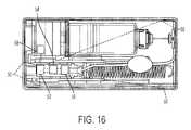
図16および図17を参照して、1つの態様において、滅菌装置(sterilizer)もまた、システム10内に設けられる。滅菌装置は、システム10の内部構成部品(inner component)を滅菌するための光源50を含む。1つの態様において、光源50は、ハウジング20の内部空洞に紫外(UV)光を供給する。光源50によって供給されるUV光は、駆動組立品12、容器14、弁組立品16、および針アクチュエータ組立品18のような内部構成部品を滅菌するように、システム10の内部構成部品に向けられる。1つの態様において、光源50は、1つまたは複数の発光ダイオード(LED)光を含む。1つの態様において、単一の光源50がハウジング20内に設けられる。また、複数の光源50がハウジング20内に設けられることも考えられる。1つの態様において、4つの光源50がハウジング20内に設けられる。1つの態様において、光源50は、システム10内の各構成部品にUV光を照らす。別の態様において、光源50は、システム10内の構成部品の一部にUV光を照らす。システム10の内側で成育または発育する全ての細菌または汚染菌(contaminants)は、ハウジング20の内側に無菌環境(sterile environment)を提供するように、UV光によって滅菌される。1つの態様において、光源50は、各々、ハウジング20の異なった内側表面に位置付けられる。 16 and 17, in one embodiment, a sterilizer is also provided within
図16および図17を再度参照して、1つの態様において、光源50は、電源52に接続される。電源52は、光源50を照らすための電力を供給することができる任意の配置であることができる。電源52は、ハウジング20内部に設けられてもよい。特に、電源52は、上部22および/または下部24に設けられてもよい。1つの態様において、電源52は、少なくとも1つの電池を含む。また、電源52は、ハウジング20の外部の電源として設けられてもよいことが考えられる。例えば、電源52は、ハウジング20に配線接続される電池パックであってもよいが、ハウジング20の外部に設けられてもよい。電源52は、交換可能および/または再充電可能であってもよい。1つの態様において、複数の電池は、光源50に電力を供給する電源52として設けられる。電池は、電気取出口(electrical outlet)に延びるコードのような外部コネクタによって、または誘導配置(induction arrangement)(不図示)によって、充填されてもよい。 Referring again to FIGS. 16 and 17, in one aspect
図16および図17を再度参照して、センサー54もまた、薬物送達作動プロセスの開始時に光源50作動させるために、ハウジング20内に設けられる。センサー54は、薬物送達作動プロセスが開始されたときを感知するように構成され、およびシステム10内の1つまたは複数の構成部品を滅菌するための光源50によってUV光が放出されるように電源52から光源50に電力を供給するように、電源52に信号を送信する。1つの態様において、センサー54は、システム10のスイッチまたはボタンの上または中に設けられる磁石56と協働するホール効果トランジスタセンサーである。1つの態様において、センサー54は、システム10の作動ボタン26上に設けられる。また、センサー54は、光源50が薬物送達作動プロセスとは無関係に作動させられ得るように、作動ボタン26から離れたスイッチまたはボタン(不図示)上に設けられ得ることも考えられる。システム10の作動ボタン26が作動させられたとき、センサー54は、光源50に電力を供給するための電源52を起動するための信号を送信する。したがって、システム10が薬物送達プロセスを始めから終わりまで進める際に、光源50はシステム10の内部構成部品を滅菌する。別の態様において、タイマー58は、起動の所定時間後に光源50が消される(turned off)こととなるように、電源52に接続される。光源50が起動されている時間の長さは、タイマー58によって調整可能である。 Referring again to Figures 16 and 17, a
図16のデバイスおよび図17の論理図を参照して、薬物送達システム10を滅菌する方法が記載される。上記されるように、薬物送達プロセスを作動させるために、作動ボタン26は押し下げられる。作動ボタン26が押し下げられるとき、作動ボタン26内に設けられた磁石56は、センサー54を作動させる。センサー54は、電源52を起動するために電源52に信号を送信する。電源52は、次いで、光源50内部でLED光を起動するために光源50に電力を供給する。光源50のLED光は、内部構成部品を滅菌するためにシステム10の内部構成部品にUV光を投げかける。1つの態様において、UV光は、駆動組立品12、容器14、弁組立品16、および針アクチュエータ組立品18のうちの少なくとも1つに投げかけられる。また、UV光は駆動組立品12、容器14、弁組立品16、および針アクチュエータ組立品18の各々に投げかけられてもよいことが考えられる。作動ボタン26が押し下げられおよび光源50が起動された状態で、所定時間後に、タイマー58は、UV光の放射(emittance)を停止するように光源50を遮断する。システム10の使用後に、使用者は、ハウジング20の内部または外部のいずれかで電源52を再充電することができる。 A method of sterilizing
1つの開示された態様の要素は、異なる組み合わせを形成するために1つまたは複数の他の開示された態様の要素と組み合わせられ得、その全ては本発明の範囲内であるとみなされる。 Elements of one disclosed aspect may be combined with elements of one or more other disclosed aspects to form different combinations, all of which are considered within the scope of the present invention.
本開示は例示的な設計を有するように記載されてきたが、本開示は、本開示の精神および範囲の中でさらに修正され得る。本出願は、したがって、その一般原則を用いる開示の任意の変形、使用、または翻案(adaptation)を包含するように意図される。さらに、本出願は、本開示の属するおよび添付される特許請求の範囲内に入る技術分野における慣行または慣例の中に入るような本開示からの逸脱を包含することが意図される。 While this disclosure has been described as having exemplary designs, this disclosure can be further modified within the spirit and scope of this disclosure. This application is therefore intended to cover any variations, uses, or adaptations of the disclosure using its general principles. Further, this application is intended to cover such departures from this disclosure as come within practice or custom in the art to which this disclosure pertains and which fall within the scope of the appended claims.
Claims (15)
Translated fromJapanese空洞を画定するハウジングと、
前記空洞内部に受け入れられおよび薬剤を受け入れるように構成される容器と、
前記空洞内部に受け入れられおよび前記容器から薬剤が放出されることを生じるように構成される駆動組立品と、
前記空洞内部に受け入れられる第1の針であって、前記第1の針は前記容器と流体連通して配置されるように構成され、および前記容器から間隔が空けられた第1の作動前位置から、前記第1の位置から間隔が空けられた第2の作動後位置に移動可能である、第1の針と、
前記第1の針と流体連通し、および使用者の皮膚を貫通するように構成される第2の針と、
を含む、針組立品と、
薬物送達プロセスを開始するための作動可能なボタンと、
前記空洞内部に受け入れられ、および前記薬物送達プロセスの開始時に、1または複数の前記容器、前記駆動組立品、および前記針組立品のうちの少なくとも一部を滅菌するように構成される滅菌装置と、
を含むことを特徴とするオンボディ型薬物送達システム。An on-body drug delivery system comprising:
a housing defining a cavity;
a container received within said cavity and configured to receive an agent;
a drive assembly configured to be received within the cavity and to cause release of a medicament from the container;
a first needle received within the cavity, the first needle configured to be placed in fluid communication with the container and in a first pre-actuation position spaced from the container; a first needle moveable from, to a second post-actuation position spaced from said first position;
a second needle in fluid communication with the first needle and configured to penetrate a user's skin;
a needle assembly comprising
an actuatable button for initiating the drug delivery process;
a sterilization device received within the cavity and configured to sterilize at least a portion of one or more of the containers, the drive assembly, and the needle assembly upon initiation of the drug delivery process; ,
An on-body drug delivery system comprising:
空洞を画定するハウジングであって、前記ハウジングは、使用者が前記空洞の少なくとも一部を見ることを可能にするように構成される窓を含む、ハウジングと、
前記空洞内部に受け入れられおよび薬剤を受け入れるように構成される薬剤容器と、
前記空洞内部に受け入れられおよび薬剤が前記薬剤容器から放出されることを生じるように構成される駆動組立品と、
前記空洞内部に受け入れられる針組立品であって、
前記薬剤容器と流体連通して配置されるように構成される第1の針であって、前記第1の針は、前記薬剤容器から間隔が空けられた第1の位置から第2の位置に移動可能であり、前記第1の針の少なくとも一部が前記薬剤容器内部に受け入れられる、第1の針と、
使用者の皮膚を貫通するように構成される第2の針であって、前記第2の針は前記第1の針と流体連通する、第2の針と、
を含む、針組立品と、
前記ハウジングに結合され、および使用者の皮膚に取り外し可能に結合するように構成される粘着性パッドと、
薬物送達プロセスを開始するための作動可能なボタンと、
前記空洞内部に受け入れられ、および前記薬物送達プロセスの開始の後で前記薬剤容器の少なくとも一部を滅菌するように構成される少なくとも1つの紫外(UV)光源と、
前記少なくとも1つのUV光源に操作可能に接続される電源と、
前記少なくとも1つのUV光源に操作可能に接続されおよび所定時間後に前記UV光源を遮断するように構成されるタイマーと、
前記薬物送達プロセスの状態を示すように構成される表示器と、
を含むことを特徴とするウェアラブルな薬物送達システム。A wearable drug delivery system comprising:
a housing defining a cavity, the housing including a window configured to allow a user to view at least a portion of the cavity;
a medicament container received within said cavity and configured to receive a medicament;
a drive assembly configured to be received within the cavity and to cause medicament to be expelled from the medicament container;
A needle assembly received within the cavity, comprising:
A first needle configured to be placed in fluid communication with the medicament container, the first needle moving from a first position to a second position spaced from the medicament container. a first needle movable, at least a portion of said first needle being received within said medicament container;
a second needle configured to penetrate the skin of a user, said second needle being in fluid communication with said first needle;
a needle assembly comprising
an adhesive pad coupled to the housing and configured to removably couple to a user's skin;
an actuatable button for initiating the drug delivery process;
at least one ultraviolet (UV) light source received within the cavity and configured to sterilize at least a portion of the drug container after initiation of the drug delivery process;
a power source operably connected to the at least one UV light source;
a timer operably connected to the at least one UV light source and configured to shut off the UV light source after a predetermined time;
an indicator configured to indicate the status of the drug delivery process;
A wearable drug delivery system comprising:
Applications Claiming Priority (3)
| Application Number | Priority Date | Filing Date | Title |
|---|---|---|---|
| US201762572715P | 2017-10-16 | 2017-10-16 | |
| US62/572,715 | 2017-10-16 | ||
| JP2021187792AJP7217331B2 (en) | 2017-10-16 | 2021-11-18 | Sterile placement for drug delivery devices |
Related Parent Applications (1)
| Application Number | Title | Priority Date | Filing Date |
|---|---|---|---|
| JP2021187792ADivisionJP7217331B2 (en) | 2017-10-16 | 2021-11-18 | Sterile placement for drug delivery devices |
Publications (2)
| Publication Number | Publication Date |
|---|---|
| JP2023041764Atrue JP2023041764A (en) | 2023-03-24 |
| JP7500790B2 JP7500790B2 (en) | 2024-06-17 |
Family
ID=64051832
Family Applications (3)
| Application Number | Title | Priority Date | Filing Date |
|---|---|---|---|
| JP2020521552AActiveJP6982174B2 (en) | 2017-10-16 | 2018-10-15 | Sterilized arrangement for drug delivery devices |
| JP2021187792AActiveJP7217331B2 (en) | 2017-10-16 | 2021-11-18 | Sterile placement for drug delivery devices |
| JP2023008140AActiveJP7500790B2 (en) | 2017-10-16 | 2023-01-23 | Sterile Configurations for Drug Delivery Devices |
Family Applications Before (2)
| Application Number | Title | Priority Date | Filing Date |
|---|---|---|---|
| JP2020521552AActiveJP6982174B2 (en) | 2017-10-16 | 2018-10-15 | Sterilized arrangement for drug delivery devices |
| JP2021187792AActiveJP7217331B2 (en) | 2017-10-16 | 2021-11-18 | Sterile placement for drug delivery devices |
Country Status (8)
| Country | Link |
|---|---|
| US (4) | US10926023B2 (en) |
| EP (1) | EP3697467A1 (en) |
| JP (3) | JP6982174B2 (en) |
| CN (2) | CN111372625B (en) |
| AU (3) | AU2018352137B2 (en) |
| CA (2) | CA3079354C (en) |
| MX (1) | MX2020003785A (en) |
| WO (1) | WO2019079174A1 (en) |
Families Citing this family (14)
| Publication number | Priority date | Publication date | Assignee | Title |
|---|---|---|---|---|
| EP1762259B2 (en) | 2005-09-12 | 2025-01-01 | Unomedical A/S | Inserter for an infusion set with a first and second spring units |
| WO2012123274A1 (en) | 2011-03-14 | 2012-09-20 | Unomedical A/S | Inserter system with transport protection |
| IL295010B1 (en) | 2015-03-10 | 2025-06-01 | Regeneron Pharma | Pollution-free piercing system and method |
| CN119950880A (en) | 2017-05-05 | 2025-05-09 | 里珍纳龙药品有限公司 | Auto-injectors and related methods of use |
| US10869961B2 (en)* | 2017-11-06 | 2020-12-22 | Sorrel Medical Ltd. | Local disinfection for drug delivery system |
| US10869960B2 (en)* | 2017-11-06 | 2020-12-22 | Sorrel Medical Ltd | Local disinfection for prefilled drug delivery system |
| US11458292B2 (en) | 2019-05-20 | 2022-10-04 | Unomedical A/S | Rotatable infusion device and methods thereof |
| US20220355033A1 (en)* | 2019-06-21 | 2022-11-10 | Preci Health Sa | Medical injection system and method |
| EP3881875A1 (en)* | 2020-03-20 | 2021-09-22 | Littringer, Eva | Delivery device for delivering a drug |
| CN115671330A (en)* | 2021-07-30 | 2023-02-03 | 通用电气精准医疗有限责任公司 | Probe disinfection device, probe disinfection method and ultrasonic imaging system |
| USD1007676S1 (en) | 2021-11-16 | 2023-12-12 | Regeneron Pharmaceuticals, Inc. | Wearable autoinjector |
| EP4197572A1 (en)* | 2021-12-17 | 2023-06-21 | Becton, Dickinson and Company | Thermoelectric generator for powering autoinjector |
| JP2025507615A (en) | 2022-02-21 | 2025-03-21 | バイエル・ヘルスケア・エルエルシー | Systems, methods and devices for the delivery of therapeutic or diagnostic agents - Patents.com |
| CN115887824B (en)* | 2022-11-04 | 2025-08-19 | 中国人民解放军火箭军特色医学中心 | Wearing formula is from injection medical kit |
Citations (3)
| Publication number | Priority date | Publication date | Assignee | Title |
|---|---|---|---|---|
| US20130303996A1 (en)* | 2012-04-16 | 2013-11-14 | Puracath Medical, Inc. | System and method for disinfecting a catheter system |
| US20150352301A1 (en)* | 2014-06-09 | 2015-12-10 | Dance Biopharm Inc. | Self-puncturing liquid drug cartridges and associated dispenser |
| JP2017500996A (en)* | 2013-12-01 | 2017-01-12 | ベクトン・ディキンソン・アンド・カンパニーBecton, Dickinson And Company | Drug device |
Family Cites Families (31)
| Publication number | Priority date | Publication date | Assignee | Title |
|---|---|---|---|---|
| US5360410A (en) | 1991-01-16 | 1994-11-01 | Senetek Plc | Safety syringe for mixing two-component medicaments |
| US20010041869A1 (en)* | 2000-03-23 | 2001-11-15 | Causey James D. | Control tabs for infusion devices and methods of using the same |
| CN1723053A (en) | 2002-09-12 | 2006-01-18 | 儿童医院医疗中心 | Method and device for painless drug injection |
| EP3695862A1 (en) | 2003-08-12 | 2020-08-19 | Becton, Dickinson and Company | Patch-like infusion device |
| HK1062765A2 (en)* | 2003-08-26 | 2004-10-29 | 颖晖实业有限公司 | Uv sterilisation air-flow chamber |
| US7449012B2 (en)* | 2004-08-06 | 2008-11-11 | Meridian Medical Technologies, Inc. | Automatic injector |
| AU2006210865B2 (en)* | 2005-02-01 | 2008-12-04 | Kaleo, Inc. | Devices, systems, and methods for medicament delivery |
| US7834328B2 (en) | 2006-01-31 | 2010-11-16 | Redmond Russell J | Method and apparatus for sterilizing intraluminal and percutaneous access sites |
| WO2007126851A2 (en)* | 2006-03-29 | 2007-11-08 | Intelliject, Llc | Devices, systems and methods for medicament delivery |
| US8431074B2 (en)* | 2008-07-29 | 2013-04-30 | Mallinckrodt Llc | Ultraviolet tubing and tip sterilizer |
| US8613719B2 (en)* | 2008-11-03 | 2013-12-24 | Calibra Medical, Inc. | Dosage sensing unit with tactile feedback |
| US9370621B2 (en)* | 2008-12-16 | 2016-06-21 | Medtronic Minimed, Inc. | Needle insertion systems and methods |
| IES20090400A2 (en) | 2009-05-22 | 2011-03-30 | Ann Marie Durkin | A sterilising apparatus |
| US9320880B2 (en)* | 2009-06-23 | 2016-04-26 | Djlm Innovations, Llc | Device for flow-through ultraviolet light decontamination of microbial contaminants |
| CA2818974A1 (en) | 2010-11-29 | 2012-06-07 | Sanofi-Aventis Deutschland Gmbh | Infusion pump drug delivery system for delivering at least two medicaments |
| ES2566179T5 (en)* | 2011-09-13 | 2019-11-14 | Unitract Syringe Pty Ltd | Connection of sterile fluid passage to medication containers for medication release pumps |
| DK3284493T3 (en) | 2012-04-13 | 2020-11-02 | Becton Dickinson Co | Micro-infusion device with automatic needle retraction |
| US9056147B2 (en)* | 2012-05-31 | 2015-06-16 | Becton, Dickinson And Company | UV disinfection system for needleless connector |
| WO2014179774A1 (en)* | 2013-05-03 | 2014-11-06 | Becton, Dickinson And Company | Drug delivery device |
| KR102082888B1 (en) | 2013-12-18 | 2020-02-28 | 마리아 패트리샤 코헨 | Uv sterilizing catheters and catheter connectors |
| CA2937327C (en)* | 2014-01-21 | 2018-02-27 | Parenteral Technologies, Llc | Force actuated injection device |
| WO2016025957A1 (en)* | 2014-08-15 | 2016-02-18 | Lifeloc Technologies, Inc | Systems and methods for surface decontamination |
| CA2994803C (en)* | 2014-08-18 | 2023-09-12 | Windgap Medical, Inc. | Portable drug mixing and delivery device and associated methods |
| CN106714872B (en)* | 2014-09-15 | 2020-07-17 | 赛诺菲 | Bulk dermal patch drug delivery device with integrated skin disinfection mechanism for injection site |
| AU2016280165A1 (en) | 2015-06-16 | 2018-02-01 | Kathryn CASHMAN | Inhalant device |
| ES2857002T3 (en) | 2015-12-03 | 2021-09-28 | Unl Holdings Llc | Systems and Procedures for Controlled Drug Delivery Pumps |
| JOP20170042B1 (en)* | 2016-02-12 | 2022-09-15 | Amgen Inc | Means of drug delivery, method of manufacture and method of use |
| US20170232185A1 (en)* | 2016-02-17 | 2017-08-17 | Acist Medical Systems, Inc. | Sterilization of fluid paths in injection system |
| CN105999482A (en)* | 2016-06-03 | 2016-10-12 | 曲建强 | Vaccination device |
| EP3348284A2 (en)* | 2017-01-12 | 2018-07-18 | Tecpharma Licensing AG | A method for sterilization of a fluid path for an injection device |
| US11040137B2 (en)* | 2017-05-19 | 2021-06-22 | Min Wei | Wearable drug delivery device |
- 2018
- 2018-10-15CACA3079354Apatent/CA3079354C/enactiveActive
- 2018-10-15USUS16/160,114patent/US10926023B2/enactiveActive
- 2018-10-15JPJP2020521552Apatent/JP6982174B2/enactiveActive
- 2018-10-15MXMX2020003785Apatent/MX2020003785A/enunknown
- 2018-10-15AUAU2018352137Apatent/AU2018352137B2/enactiveActive
- 2018-10-15WOPCT/US2018/055865patent/WO2019079174A1/ennot_activeCeased
- 2018-10-15EPEP18796332.7Apatent/EP3697467A1/enactivePending
- 2018-10-15CNCN201880075658.5Apatent/CN111372625B/enactiveActive
- 2018-10-15CACA3163187Apatent/CA3163187A1/enactivePending
- 2018-10-15CNCN202210371032.7Apatent/CN114712534B/enactiveActive
- 2021
- 2021-01-20USUS17/153,613patent/US12115335B2/enactiveActive
- 2021-05-18AUAU2021203196Apatent/AU2021203196B2/enactiveActive
- 2021-11-18JPJP2021187792Apatent/JP7217331B2/enactiveActive
- 2023
- 2023-01-23JPJP2023008140Apatent/JP7500790B2/enactiveActive
- 2023-02-17AUAU2023200940Apatent/AU2023200940B2/enactiveActive
- 2023-02-28USUS18/115,369patent/US11878140B2/enactiveActive
- 2023-02-28USUS18/115,349patent/US20230201447A1/enactivePending
Patent Citations (3)
| Publication number | Priority date | Publication date | Assignee | Title |
|---|---|---|---|---|
| US20130303996A1 (en)* | 2012-04-16 | 2013-11-14 | Puracath Medical, Inc. | System and method for disinfecting a catheter system |
| JP2017500996A (en)* | 2013-12-01 | 2017-01-12 | ベクトン・ディキンソン・アンド・カンパニーBecton, Dickinson And Company | Drug device |
| US20150352301A1 (en)* | 2014-06-09 | 2015-12-10 | Dance Biopharm Inc. | Self-puncturing liquid drug cartridges and associated dispenser |
Also Published As
| Publication number | Publication date |
|---|---|
| BR112020007283A2 (en) | 2020-11-03 |
| MX2020003785A (en) | 2020-08-03 |
| US20210138147A1 (en) | 2021-05-13 |
| AU2021203196B2 (en) | 2022-11-17 |
| JP2022010393A (en) | 2022-01-14 |
| WO2019079174A1 (en) | 2019-04-25 |
| CA3163187A1 (en) | 2019-04-25 |
| AU2018352137B2 (en) | 2021-02-18 |
| AU2021203196A1 (en) | 2021-06-10 |
| CA3079354C (en) | 2022-08-30 |
| AU2023200940B2 (en) | 2024-11-14 |
| CA3079354A1 (en) | 2019-04-25 |
| US20230201448A1 (en) | 2023-06-29 |
| JP7500790B2 (en) | 2024-06-17 |
| CN114712534A (en) | 2022-07-08 |
| JP2020536699A (en) | 2020-12-17 |
| US11878140B2 (en) | 2024-01-23 |
| JP6982174B2 (en) | 2021-12-17 |
| CN111372625A (en) | 2020-07-03 |
| US10926023B2 (en) | 2021-02-23 |
| US20190111202A1 (en) | 2019-04-18 |
| US12115335B2 (en) | 2024-10-15 |
| AU2023200940A1 (en) | 2023-03-23 |
| AU2018352137A1 (en) | 2020-05-07 |
| CN111372625B (en) | 2022-04-29 |
| US20230201447A1 (en) | 2023-06-29 |
| JP7217331B2 (en) | 2023-02-02 |
| EP3697467A1 (en) | 2020-08-26 |
| CN114712534B (en) | 2024-09-10 |
Similar Documents
| Publication | Publication Date | Title |
|---|---|---|
| JP7217331B2 (en) | Sterile placement for drug delivery devices | |
| ES2498741T3 (en) | Administration device for use with a therapeutic drug | |
| JP6130377B2 (en) | Insertion mechanism for drug delivery pump | |
| CN109843353A (en) | For connecting drug delivery device and method using relevant fluid flow path | |
| US20150209505A1 (en) | Controlled delivery drive mechanisms for drug delivery pumps | |
| US20230338645A1 (en) | Time Delay Mechanism for a Hydraulic Drug Delivery Device | |
| AU2013290144A1 (en) | Insertion mechanisms having vented fluid pathways for drug delivery pumps | |
| AU2014209195A1 (en) | Flow restriction mechanisms for drug delivery pumps | |
| KR20030076666A (en) | Liquid delivery device and method for operating an ejecting device | |
| JP2023507164A (en) | Liquid drug pump with flexible drug reservoir | |
| BR112020007283B1 (en) | DRUG DELIVERY SYSTEM FOR INJECTING A MEDICATION | |
| JP2023539762A (en) | Fluid transfer systems for drug delivery devices | |
| HK1089355A (en) | Liquid delivery device and method for operating an ejecting device |
Legal Events
| Date | Code | Title | Description |
|---|---|---|---|
| A521 | Request for written amendment filed | Free format text:JAPANESE INTERMEDIATE CODE: A523 Effective date:20230221 | |
| A621 | Written request for application examination | Free format text:JAPANESE INTERMEDIATE CODE: A621 Effective date:20230221 | |
| A131 | Notification of reasons for refusal | Free format text:JAPANESE INTERMEDIATE CODE: A131 Effective date:20231003 | |
| A521 | Request for written amendment filed | Free format text:JAPANESE INTERMEDIATE CODE: A523 Effective date:20240104 | |
| TRDD | Decision of grant or rejection written | ||
| A01 | Written decision to grant a patent or to grant a registration (utility model) | Free format text:JAPANESE INTERMEDIATE CODE: A01 Effective date:20240507 | |
| A61 | First payment of annual fees (during grant procedure) | Free format text:JAPANESE INTERMEDIATE CODE: A61 Effective date:20240605 | |
| R150 | Certificate of patent or registration of utility model | Ref document number:7500790 Country of ref document:JP Free format text:JAPANESE INTERMEDIATE CODE: R150 |