JP2023038720A - Information processing device, information processing method, and program - Google Patents
Information processing device, information processing method, and programDownload PDFInfo
- Publication number
- JP2023038720A JP2023038720AJP2021145590AJP2021145590AJP2023038720AJP 2023038720 AJP2023038720 AJP 2023038720AJP 2021145590 AJP2021145590 AJP 2021145590AJP 2021145590 AJP2021145590 AJP 2021145590AJP 2023038720 AJP2023038720 AJP 2023038720A
- Authority
- JP
- Japan
- Prior art keywords
- information processing
- control unit
- value
- artery
- boundary
- Prior art date
- Legal status (The legal status is an assumption and is not a legal conclusion. Google has not performed a legal analysis and makes no representation as to the accuracy of the status listed.)
- Pending
Links
Images


Landscapes
- Apparatus For Radiation Diagnosis (AREA)
Abstract
Description
Translated fromJapanese本発明は、情報処理装置、情報処理方法及びプログラムに関する。 The present invention relates to an information processing device, an information processing method, and a program.
動脈解離の診断としてCT検査と造影CT検査とを組み合わせたものが知られている(特許文献1参照)。 A combination of CT examination and contrast-enhanced CT examination is known for diagnosing arterial dissection (see Patent Document 1).
造影CT検査を行うことは、造影剤によるアレルギー等、患者の負担になる。また、救急の現場等において、一刻も早く動脈解離ではないことを確かめたいという要望がある。 Performing a contrast-enhanced CT examination imposes a burden on the patient, such as an allergy to the contrast medium. In addition, there is a demand at the scene of an emergency, etc., to confirm as soon as possible that there is no arterial dissection.
本発明の一態様によれば、情報処理装置が提供される。この情報処理装置は、制御部を有する。制御部は、被測定者の体内のスキャン情報を受け取り、スキャン情報に基づいて、動脈を基準に特定される特定領域のCT値を求める。CT値と、動脈解離に関する閾値と、を出力する。 According to one aspect of the present invention, an information processing device is provided. This information processing device has a control unit. The control unit receives scan information on the inside of the body of the subject, and based on the scan information, obtains a CT value of a specific region specified based on the artery. Output the CT value and the threshold for arterial dissection.
以下、図面を用いて本発明の実施形態について説明する。以下に示す実施形態中で示した各種特徴事項は、互いに組み合わせ可能である。 Embodiments of the present invention will be described below with reference to the drawings. Various features shown in the embodiments shown below can be combined with each other.
ところで、本実施形態に登場するソフトウェアを実現するためのプログラムは、コンピュータが読み取り可能な非一時的な記録媒体(Non-Transitory Computer-Readable Medium)として提供されてもよいし、外部のサーバからダウンロード可能に提供されてもよいし、外部のコンピュータで当該プログラムを起動させてクライアント端末でその機能を実現(いわゆるクラウドコンピューティング)するように提供されてもよい。 By the way, the program for realizing the software appearing in this embodiment may be provided as a non-transitory computer-readable medium (Non-Transitory Computer-Readable Medium), or may be downloaded from an external server. It may be provided as possible, or may be provided so that the program is activated on an external computer and the function is realized on the client terminal (so-called cloud computing).
また、本実施形態において「部」とは、例えば、広義の回路によって実施されるハードウェア資源と、これらのハードウェア資源によって具体的に実現されうるソフトウェアの情報処理とを合わせたものも含みうる。また、本実施形態においては様々な情報を取り扱うが、これら情報は、例えば電圧・電流を表す信号値の物理的な値、0又は1で構成される2進数のビット集合体としての信号値の高低、又は量子的な重ね合わせ(いわゆる量子ビット)によって表され、広義の回路上で通信・演算が実行されうる。 Further, in the present embodiment, the term “unit” may include, for example, a combination of hardware resources implemented by circuits in a broad sense and software information processing that can be specifically realized by these hardware resources. . In addition, various information is handled in the present embodiment, and these information are, for example, physical values of signal values representing voltage and current, and signal values as binary bit aggregates composed of 0 or 1. It is represented by high and low, or quantum superposition (so-called quantum bit), and communication and operation can be performed on a circuit in a broad sense.
また、広義の回路とは、回路(Circuit)、回路類(Circuitry)、プロセッサ(Processor)、及びメモリ(Memory)等を少なくとも適当に組み合わせることによって実現される回路である。すなわち、特定用途向け集積回路(Application Specific Integrated Circuit:ASIC)、プログラマブル論理デバイス(例えば、単純プログラマブル論理デバイス(Simple Programmable Logic Device:SPLD)、複合プログラマブル論理デバイス(Complex Programmable Logic Device:CPLD)、及びフィールドプログラマブルゲートアレイ(Field Programmable Gate Array:FPGA))等を含むものである。 A circuit in a broad sense is a circuit implemented by appropriately combining at least circuits, circuits, processors, memories, and the like. Application Specific Integrated Circuits (ASICs), programmable logic devices (e.g., Simple Programmable Logic Devices (SPLDs), Complex Programmable Logic Devices (CPLDs), and field It includes a programmable gate array (Field Programmable Gate Array: FPGA).
[実施形態1]
<1.システム構成>
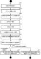
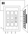
図1は、実施形態1に係る情報処理システム100のシステム構成の一例を示す図である。
図1に示されるように、情報処理システム100は、情報処理装置110と、CT装置120と、を含む。なお、CT装置のCTは、Computed Tomographの略であり、後述するCT値、造影CT等のCTについても同様である。情報処理装置110は、有線通信又は無線通信を介してCT装置120と通信可能に接続されている。情報処理装置110は、実施形態に係る処理を実行する。例えば、情報処理装置110は、被測定者の体内のスキャン画像を受け取り、スキャン画像に基づいて、動脈を基準に特定される特定領域の所定のパラメータ値を求める。情報処理装置110は、パラメータ値と、動脈解離に関する閾値と、を出力する。これにより、一刻も早く動脈解離ではないことを確かめることができる。[Embodiment 1]
<1. System configuration>
FIG. 1 is a diagram showing an example of the system configuration of an
As shown in FIG. 1 , the
<2.ハードウェア構成>
本節では、本実施形態のハードウェア構成について説明する。<2. Hardware Configuration>
This section describes the hardware configuration of this embodiment.
<2.1.情報処理装置110のハードウェア構成>
以下、情報処理装置110のハードウェア構成について説明する。<2.1. Hardware Configuration of
The hardware configuration of the
図2は、実施形態1に係る情報処理装置110のハードウェア構成の一例を示す図である。
情報処理装置110は、制御部201と、記憶部202と、通信部203と、入力部204と、出力部205とを有し、これらの構成要素が情報処理装置110の内部において通信バスを介して電気的に接続されている。各構成要素についてさらに説明する。FIG. 2 is a diagram showing an example of the hardware configuration of the
The
制御部201は、情報処理装置110に関連する全体動作の処理及び制御を行う。制御部201は、例えば中央処理装置(Central Processing Unit:CPU)である。制御部201が、記憶部202に記憶された所定のプログラムを読み出し、プログラムに基づき処理を実行することによって、情報処理装置110に係る種々の機能、例えば、後述する図4に示される処理が実現される。なお、制御部201は単一であることに限定されず、機能ごとに複数の制御部201を有するように実施してもよい。またそれらの組合せであってもよい。 The
記憶部202は、前述の記載により定義される様々な情報を記憶する。これは、例えば、制御部201によって実行される情報処理装置110に係る種々のプログラム等を記憶するソリッドステートドライブ(Solid State Drive:SSD)等のストレージデバイスとして、又は、プログラムの演算に係る一時的に必要な情報(引数、配列等)を記憶するランダムアクセスメモリ(Random Access Memory:RAM)等のメモリとして実施されうる。記憶部202は、制御部201によって実行される情報処理装置110に係る種々のプログラム、変数及び制御部201がプログラムに基づき処理を実行する際に用いるデータ等を記憶している。 The
通信部203は、USB、IEEE1394、Thunderbolt、有線LANネットワーク通信等といった有線型の通信手段が好ましいものの、無線LANネットワーク通信、3G/LTE/5G等のモバイル通信、Bluetooth(登録商標)通信等を必要に応じて含めてもよい。すなわち、これら複数の通信手段の集合として実施することがより好ましい。すなわち、情報処理装置110は、通信部203を介して、CT装置120又は外部から種々の情報を通信してもよい。 The
入力部204は、情報処理装置110の筐体に含まれるものでもよいし、外付けされるものでもよい。例えば、入力部204は、出力部205と一体となってタッチパネルとして実施されてもよい。タッチパネルであれば、ユーザは、タップ操作、スワイプ操作等を入力することができる。もちろん、タッチパネルに代えて、スイッチボタン、マウス、QWERTYキーボード等を採用してもよい。すなわち、入力部204がユーザによってなされた操作入力を受け付ける。当該入力が命令信号として、通信バスを介して制御部201に転送され、制御部201が必要に応じて所定の制御又は演算を実行しうる。 The
出力部205は、例えば、情報処理装置110の筐体に含まれるものでもよいし、外付けされるものでもよい。出力部205は、ユーザが操作可能なグラフィカルユーザインターフェース(Graphical User Interface:GUI)の画面を表示する。これは例えば、CRTディスプレイ、液晶ディスプレイ、有機ELディスプレイ及びプラズマディスプレイ等の表示デバイスを、情報処理装置110の種類に応じて使い分けて実施することが好ましい。出力部205の一例として、後述する表示部500が含まれる。 For example, the
<2.2.CT装置120のハードウェア構成>
以下、CT装置120のハードウェア構成について説明する。<2.2. Hardware Configuration of
The hardware configuration of the
図3は、実施形態1に係るCT装置120のハードウェア構成の一例を示す図である。
CT装置120は、制御部301と、記憶部302と、通信部303と、X線発生部304と、X線検出部305と、移動台部306とを有し、これらの構成要素がCT装置120の内部において通信バスを介して電気的に接続されている。各構成要素についてさらに説明する。FIG. 3 is a diagram showing an example of the hardware configuration of the
The
制御部301、記憶部302、通信部303の具体的な説明については、先述の情報処理装置110における制御部201、記憶部202及び通信部203の記載を参照されたい。 For specific descriptions of the
X線発生部304は、ドーナツ形状のCT装置120の円周上に設けられている。X線発生部304は、ドーナツ内を移動可能に構成されている。X線発生部304は、X線管を有し、X線管により生成したX線をドーナツ状のCT装置120の内側に向かって照射する。X線発生部304から照射されたX線は、経路上の被測定者に吸収されることで減衰する。 The
X線検出部305は、ドーナツ形状のCT装置120の円周上、かつ、X線発生部304の向かい側に設けられている。X線検出部305は、X線発生部304により生成したX線を検出するようにドーナツ内を移動可能に構成されている。X線検出部305は、減衰したX線量を検出することで、被測定者の体内の情報を取得する。 The
移動台部306は、ドーナツ形状のCT装置120の円の中を垂直方向に移動可能に構成されている。移動台部306は、CT装置120による測定の前後に被測定者の出し入れを可能にしたり、CT装置120による測定中に様々な断面での被測定者の測定を可能にしたりするために移動する。 The moving
<3.情報処理方法>
本節では、前述した情報処理装置110によって実行される情報処理方法について説明する。<3. Information processing method>
In this section, an information processing method executed by the
<3.1.情報処理の概要>
図4は、実施形態1に係る情報処理の一例を示すアクティビティ図である。<3.1. Overview of information processing>
FIG. 4 is an activity diagram showing an example of information processing according to the first embodiment.
<3.1.1.三次元画像の生成>
A401において、情報処理装置110の制御部201は、入力部204を介して、ユーザからの処理の実行を受け付ける。制御部201は、通信部203及びCT装置120の通信部303を介して、体内のスキャン情報を取得するようCT装置120に指示する。情報処理装置110からの指示を受けて、CT装置120の制御部301は、記憶部302内のプログラムを基に、X線発生部304、X線検出部305及び移動台部306をそれぞれ稼動させ、被測定者の体内のスキャン情報を取得し、記憶部302に保存する。<3.1.1. Generation of 3D Image>
At A<b>401 , the
A402において、制御部301は、通信部303を介して、情報処理装置110にスキャン情報を送信する。 In A<b>402 , the
A403において、制御部201は、スキャン画像を基に、被測定者の三次元画像を生成する。三次元画像の生成方法は、二次元のCT画像を積み重ねて三次元画像にする方法、ヘリカルCT等の被測定者を螺旋状にスキャンすることで連続的に得られた三次元のCT情報を基に三次元画像を生成する方法等がある。三次元画像には、心臓等の臓器及び動脈、静脈等の血管等が三次元化された画像情報が含まれる。 At A403, the
A404において、制御部201は、生成した三次元画像を出力部205に表示する。A401からA404までについては、図5を用いて詳述する。 At A<b>404 , the
<3.1.2.大動脈と血管周囲脂肪の間の境界の特定>
A405において、制御部201は、入力部204を介してユーザにより又はプログラムに基づいて大動脈を特定する。<3.1.2. Identification of the boundary between the aorta and perivascular fat >
At A405, the
A406において、制御部201は、特定した大動脈を直線状に伸ばして出力部205に表示する。 In A<b>406 , the
A407において、制御部201は、入力部204を介してユーザにより又はプログラムに基づいて大動脈と血管周囲脂肪の間の境界を特定する。A405からA407までについては、図6を用いて詳述する。 At A407, the
<3.1.3.大動脈解離の判定>
A408において、制御部201は、特定した境界から所定の距離だけ離れた位置の血管周囲脂肪のCT値を測定する。なお、CT値とは、水を0、空気を-1000に設定された条件下で、CT撮影された物質(組織)の密度を原点の水に対する相対値として表現する値である。また、CT値の単位は、HU(Hounsfield Units)で表される。<3.1.3. Determination of aortic dissection>
In A408, the
A409において、制御部201は、CT値が所定の範囲内である場合、A410の処理に進み、CT値が所定の範囲外である場合、A412に進む。 At A409, if the CT value is within the predetermined range, the
CT値が所定の範囲内である場合、A410において、制御部201は、測定したCT値と、大動脈解離の閾値と、大動脈解離の可能性は低いという結果と、を出力部205に表示する。CT値が所定の範囲内である場合のA408からA410までの流れについては、図7を用いて詳述する。 If the CT value is within the predetermined range, in A410, the
CT値が所定の範囲外である場合、A411において、制御部201は、測定したCT値と、大動脈解離の閾値と、造影CTを推奨するという結果と、を出力部205に表示する。CT値が所定の範囲内である場合のA408、A409及びA411の流れについては、図8を用いて詳述する。 If the CT value is outside the predetermined range, at A411, the
<3.2.情報処理の詳細>
続いて、前述した情報処理の詳細を説明する。<3.2. Information processing details>
Next, the details of the information processing described above will be described.
<3.2.1.三次元画像の生成>
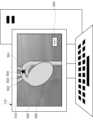
図5は、実施形態1に係る三次元画像生成時における表示部500の一例を示す図である。
情報処理装置110の表示部500には、三次元化された被測定者の内部の画像が表示されている。被測定者の内部の画像には、大動脈501及び動脈502、503、504、静脈等の血管と、心臓505等の臓器と、選択箇所510と、詳細表示ボタン520が含まれる。大動脈501には、上行大動脈、弓部大動脈、下行大動脈等が含まれる。また、動脈には、腕頭動脈502、左総頸動脈503、左鎖骨下動脈504等が含まれる。心臓505から大動脈501を介して各動脈502、503、504へ血液が送られることで、体内に血液を送り出している。<3.2.1. Generation of 3D Image>
FIG. 5 is a diagram showing an example of the
The
選択箇所510は、ユーザにより指定された箇所、又はプログラムにより特定された箇所を表示しているマークである。本実施形態では、大動脈弓の箇所に選択箇所510が付されている。詳細表示ボタン520は、操作されることにより、選択された箇所を拡大して表示するように表示部500を遷移させる。 The selected
制御部201は、CT装置120から取得した複数の断層画像又は三次元のCT値情報等のスキャン情報を基に、大動脈501、動脈502、503、504、心臓505等を含む三次元画像を生成する。制御部201は、生成した三次元画像を表示部500に表示する。制御部201は、選択された選択箇所510を表示部500に表示する。さらに、制御部201は、入力部204を介してユーザに選択された箇所を選択箇所510としたり、所定のプログラムの実行により選択された箇所を選択箇所510としたりして表示部500に表示することができる。この所定のプログラムは、例えば、画像解析により形状に異常が見られた箇所、CT値に異常が見られた箇所等を選択箇所510とするプログラムである。選択箇所510が選択された後に、詳細表示ボタン520が操作されたとき、制御部201は、図6に示すように、選択箇所510の大動脈501又は動脈502、503、504をより詳細に表示部500に表示する。これにより、3次元の画像を確認しながら、詳細を確認したい箇所を表示することができる。 The
<3.2.2.大動脈と血管周囲脂肪の間の境界の特定>
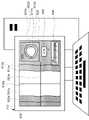
図6は、実施形態1に係る大動脈の詳細の表示中における表示部500の一例を示す図である。
情報処理装置110の表示部500には、大動脈501a、bと、血管周囲脂肪602a、bと、中心線610と、境界線611a、bと、特定領域線612a、bと、断面線613aと、断面情報620と、判定開始ボタン630と、参考FAI値情報640と、が含まれる。<3.2.2. Identification of the boundary between the aorta and perivascular fat>
FIG. 6 is a diagram showing an example of the
The
血管周囲脂肪602a、bは、大動脈a、bの周囲を覆う脂肪であり、CT値の濃度に応じて色の濃淡で表示されている。境界線611a、bは、大動脈501a、bと、血管周囲脂肪602a、bとの境界を表す線である。特定領域線612a、bは、境界線611a、bから血管周囲脂肪602a、b側に所定の距離だけ離れている線である。断面線613aは、断面情報620を表示する箇所を表示する線である。断面情報620は、断面線613aが引かれた箇所の大動脈501a、b及び血管周囲脂肪602a、bの断面を表示する情報である。判定開始ボタン630は、操作されることにより、大動脈解離を起こしていないかの判定を開始し、表示部500を遷移させる。 The
参考FAI値情報640は、色と血管周囲脂肪602a、bのCT値を対応させている情報であり、これを参照することにより所定の箇所の血管周囲脂肪602a、bのCT値を視覚的に認識することができる。なお、血管周囲脂肪のCT値に色分けして表示されたものは、血管周囲脂肪減衰指数(FAI(perivascular Fat Attenuation Index)値)と呼ばれる。FAI値は、冠状動脈炎症を評価する指標として知られており、単位は、CT値と同様にHUで表される。本明細書中において、CT値には、FAI値等のCT値から求められた二次的なパラメータが含まれるものとする。The reference
制御部201は、大動脈501が撮像されたスキャン情報から大動脈部分を抽出する。次に、制御部201は、抽出した大動脈部分のうち、選択箇所510の周辺(本実施形態では、大動脈弓の周辺)を直線状に伸ばして表示する画像処理を実行する。さらに、制御部201は、大動脈501a、bと、大動脈501a、bを囲む血管周囲脂肪602a、bと、の境界線611a、bを特定する。ここで、制御部201は、境界からの所定の距離の場所を特定領域線612a,bとする。このとき、境界からの所定の距離は、大動脈501a、bの半径よりも小さい。なお、一般的な胸部大動脈の直径は約3cm程であり、腹部大動脈の直径は約2cm程として知られている。また、このとき、制御部201は、表示部500を介した入力操作に基づいて境界線611a、bを特定してもよい。描画により特定する場合、制御部201は、入力部204を介して、ユーザによる線の描画を受け付け、引かれた線を境界線611a、bとして特定する。また、制御部201は、CT値に基づいて境界線611a、bを特定してもよい。CT値に基づいて特定する場合、制御部201は、記憶部202に予め記憶されている動脈及び血管周囲脂肪のCT値の参考値と、CT値の測定値とを用いて、動脈部分と、血管周囲脂肪部分とをそれぞれ判定し、線状にCT値の変化が見られる部分を境界線611a、bと特定する。さらに、制御部201は、大動脈501の断面の形状に基づいて境界線611a、bを特定してもよい。動脈の断面の形状に基づいて特定する場合、制御部201は、記憶部202に予め記憶されている動脈の断面形状と、画像認識により特定した動脈の断面形状とを用いて動脈部分と血管周囲脂肪部分とをそれぞれ判定した上で境界線611a、bを特定する。また、上述した、描画、CT値、動脈の断面の形状等の境界線611a、bの特定方法は、任意に組み合わせることができる。これにより、動脈部分と血管周囲脂肪部分とを適切に判別することができる。 The
また、制御部201は、機械学習された学習済みモデルを用いて、境界線611a、b又は特定領域線612a、bの特定を行ってもよい。すなわち、制御部201は、過去の境界線611a、bの特定の結果に基づいて、境界線611a、b又は特定領域線612a、bの特定を行うことができる。具体的には、制御部201は、学習モデルを用いる制御部201への入力データと出力データとの組み合わせを、学習データとして複数個準備し、それらから機械学習によって知識を獲得し、獲得した知識に基づいて入力データに対する出力データを結果として出力する学習済みモデルを作成する。学習済みモデルは、例えばニューラルネットワークモデルで構成することができる。例えば、制御部201において学習済みモデルを用いる場合、例えば、制御部201は、描画、CT値、動脈の断面の形状等により境界線611a、bを特定する度に、その箇所のCT値、断面形状等から学習データを生成し、機械学習を実行することで、学習済みモデルを生成する。また、制御部201は、特定領域線612a、bの特定する際の境界からの所定の距離においても、CT値、動脈の断面の形状等から学習データを生成し、機械学習を実行することで、学習済みモデルを生成する。なお、学習済みモデルは、必要に応じて一定の処理後に更新してもよい。これらの学習済みモデルを用いることで、境界線611a、b又は特定領域線612a、bを精度良く特定することができる。 In addition, the
さらに、制御部201は、判定した血管周囲脂肪部分について、CT値に基づいた色分けを行う。制御部201は、直線状に伸ばされた大動脈501aと、選択箇所510の大動脈501bの断面と、血管周囲脂肪602a、bと、特定した境界線611a、bと、特定領域線612a、bと、血管周囲脂肪602a、bのCT値の色分け結果と、を表示部500に表示する。これにより、選択箇所の大動脈の様子を詳細に把握することができる。 Further, the
<3.2.3.大動脈解離の可能性が低い場合の処理>
図7では、図6において、被測定者が動脈解離の可能性が低い状態で判定開始ボタン630が操作された場合に表示される結果を説明する。
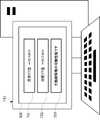
図7は、実施形態1に係る動脈解離の可能性が低い場合の測定結果を表示する表示部500の一例を示す図である。
情報処理装置110の表示部500には、動脈解離に関する閾値701と、測定したCT値702と、判定結果703と、が含まれる。動脈解離に関する閾値701は、動脈解離が起こっていないことを判定するための閾値である。測定したCT値702は、血管周囲脂肪の特定箇所のCT値である。判定結果703は、動脈解離に関する閾値701と、測定したCT値702と、に基づいて出力される結果である。図7では、測定したCT値702が、動脈解離に関する閾値701を下回っているので、動脈解離を起こしていないと判定し、その結果が表示されている。<3.2.3. Treatment when the possibility of aortic dissection is low>
FIG. 7 will explain the result displayed when the
FIG. 7 is a diagram showing an example of the
The
制御部201は、判定開始ボタン630が操作された場合に、特定箇所のCT値を測定する。すなわち、制御部201は、被測定者の体内のスキャン情報を受け取り、スキャン情報に基づいて動脈を基準に特定される特定領域のCT値を求める。次に、制御部201は、動脈解離に関する閾値701と、測定したCT値702と、を表示部500に出力する。さらに、制御部201は、動脈解離に関する閾値701と、測定したCT値702と、に基づき、被測定者が動脈解離ではないといえるかを判定し、その判定結果703をさらに出力する。これにより、動脈解離ではないといえるかを容易に判定することができる。 The
<3.2.4.大動脈解離が疑われる場合の処理>
図8では、図6において、被測定者が動脈解離の可能性がある状態で判定開始ボタン630が操作された場合に表示される結果を説明する。
図8は、実施形態1に係る動脈解離の可能性が疑われる場合の測定結果を表示する表示部500の一例を示す図である。
情報処理装置110の表示部500には、動脈解離に関する閾値701と、測定したCT値802と、判定結果803と、が含まれる。測定したCT値802は、動脈解離が疑われる動脈の血管周囲脂肪のCT値である。判定結果803は、動脈解離に関する閾値701と、測定したCT値802と、に基づいて出力される結果である。
図8では、測定したCT値802が、動脈解離に関する閾値701を上回っているので、動脈解離を起こしていないと判断できないため、造影CTを推奨するという結果を表示している。<3.2.4. Treatment when aortic dissection is suspected>
FIG. 8 will explain the results displayed when the
FIG. 8 is a diagram showing an example of the
The
In FIG. 8, the measured
制御部201は、判定開始ボタン630が操作された場合に、動脈解離に関する閾値701と、動脈解離が疑われる動脈の血管周囲脂肪のCT値802と、に基づき、造影剤を用いたスキャンを追加しなくてもよいか判定し、判定結果803を出力する。これにより、動脈解離を起こしている可能性が疑われる場合に造影CTに誘導することができる。 When the
<3.3.測定結果>
続いて、図9ないし図11を用いて、本発明者らが測定により導いた結果を説明する。<3.3. Measurement result>
Next, the results obtained by the inventors' measurements will be described with reference to FIGS. 9 to 11. FIG.
<3.3.1.境界からの距離とCT値との関係>
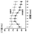
図9は、動脈解離を起こしている被測定者及び動脈解離を起こしてない被測定者の大動脈と血管周囲脂肪の境界からの距離とCT値との関係をプロットした測定結果の一例を示す図である。
動脈解離を起こしている例と動脈解離を起こしてない例のCT値を比較すると、特に10mm以内の範囲において優位な差が見られ、特に境界から1mmの距離においてさらに優位な差がみられた。よって、境界により近い部分において、CT値を測定することにより、動脈解離を起こしているか否かの判定を行うことができる。
大動脈と血管周囲脂肪の境界からの距離は、随時最適化されてもよい。具体的な手法については、先述の機械学習された学習済みモデルに関する記載を参照されたい。これにより、大動脈と血管周囲脂肪の境界からの最適な距離を導くことができる。<3.3.1. Relationship between distance from boundary and CT value>
FIG. 9 is a diagram showing an example of measurement results plotting the relationship between the distance from the boundary between the aorta and perivascular fat and the CT value of a subject with arterial dissection and a subject without arterial dissection. is.
Comparing the CT values of cases with arterial dissection and those without arterial dissection, a significant difference was observed within a range of 10 mm, and a further significant difference was observed at a distance of 1 mm from the boundary. . Therefore, by measuring the CT value in a portion closer to the boundary, it is possible to determine whether or not arterial dissection has occurred.
The distance from the aorta-perivascular fat boundary may be optimized from time to time. For a specific method, see the description of the previously machine-learned trained model. This allows the optimal distance from the aorta-perivascular fat boundary to be derived.
<3.3.2.動脈解離を起こしている場合のCT値>
図10は、動脈解離を起こしている複数の被測定者と動脈解離を起こしてない複数の被測定者の境界から1mm離れた血管周囲脂肪におけるCT値をプロットした測定結果の一例を示す図である。
図10によると、動脈解離を起こしていない被測定者のCT値には、ばらつきがあったため、優位な差はわからなかった。一方で、動脈解離を起こしている被測定者のCT値からは、-82.92HUより高い傾向があることがわかった。さらに、動脈解離を起こしている被測定者のCT値からは、-85.91HUより高い傾向があることがわかった。実施形態1において、動脈解離に関する閾値701は、-82.92HUのみであったが、さらに、-85.91HUにも閾値を設けてもよい。<3.3.2. CT value in case of arterial dissection>
FIG. 10 is a diagram showing an example of measurement results plotting the CT values of perivascular fat 1 mm away from the boundary between a plurality of subjects with arterial dissection and a plurality of subjects without arterial dissection. be.
According to FIG. 10, the CT values of subjects without arterial dissection varied, so no significant difference was found. On the other hand, it was found that the CT values of subjects with arterial dissection tended to be higher than -82.92 HU. Furthermore, it was found that the CT values of subjects with arterial dissection tended to be higher than -85.91 HU. In
閾値を複数設ける場合、制御部201は、動脈解離の可能性に差をつけて判定結果をつけて表示部500に表示する。具体的には、制御部201は、CT値が-82.92HU以上の場合は、造影CTを推奨する画面を表示部500に表示し、CT値が-82.92HU未満かつ-85.91HU以上の場合は、動脈解離の可能性は低いという画面を表示部500に表示し、CT値が-85.91HU未満の場合は、動脈解離の可能性は無いという画面を表示部500に表示する。
また、動脈解離の判定に用いられるCT値の閾値は、随時最適化されてもよい。具体的な手法については、先述の機械学習された学習済みモデルに関する記載を参照されたい。これにより、動脈解離の判定に用いられる最適なCT値の閾値を導くことができる。When a plurality of threshold values are provided, the
In addition, the CT value threshold used to determine arterial dissection may be optimized as needed. For a specific method, see the description of the previously machine-learned trained model. This makes it possible to derive the optimum CT value threshold used for determination of arterial dissection.
<3.3.3.CT値の視覚的な比較>
図11は、動脈解離を起こしている被測定者と動脈解離を起こしてない被測定者の血管周囲脂肪のCT値を表示した測定結果の一例を示す図である。
図11では、CT値の大小をわかりやすく視認するため、CT値のマーカーであるFAI値を表示している。
図11より、動脈解離を起こしていない被測定者では、CT値が全体的に低めに分布しており、一方で、動脈解離を起こしている被測定者では、CT値が全体的に高めに分布していることがわかる。
以上、実施形態1によれば、造影剤によるアレルギー等、患者の負担にならずに、また、救急の現場等において、一刻も早く大動脈解離ではないことを確かめることができる。<3.3.3. Visual comparison of CT values>
FIG. 11 is a diagram showing an example of measurement results displaying CT values of perivascular fat of a subject with arterial dissection and a subject without arterial dissection.
In FIG. 11, the FAI value, which is a marker of the CT value, is displayed in order to visually recognize the magnitude of the CT value in an easy-to-understand manner.
As shown in FIG. 11, the CT values of the subjects who did not have arterial dissection tended to be lower overall, while the CT values of the subjects who had arterial dissection tended to be higher overall. It can be seen that they are distributed.
As described above, according to
次に記載の各態様で提供されてもよい。
前記情報処理装置において、前記制御部は、前記CT値と、前記閾値と、に基づき、前記被測定者が動脈解離ではないといえるかを判定し、判定結果をさらに出力する、情報処理装置。
前記情報処理装置において、前記制御部は、前記CT値と、前記閾値と、に基づき、造影剤を用いたスキャンを追加しなくてもよいかを判定し、判定結果をさらに出力する、情報処理装置。
前記情報処理装置において、前記制御部は、前記動脈と、前記動脈を囲む血管周囲脂肪と、の境界を特定し、前記境界からの所定の距離の場所を前記特定領域とする、情報処理装置。
前記情報処理装置において、前記制御部は、画面を介した入力操作に基づいて前記境界を特定する、情報処理装置。
前記情報処理装置において、前記制御部は、前記CT値に基づいて前記境界を特定する、情報処理装置。
前記情報処理装置において、前記制御部は、前記動脈の断面の形状に基づいて前記境界を特定する、情報処理装置。
前記情報処理装置において、前記所定の距離は、前記動脈の半径よりも小さい、情報処理装置。
前記情報処理装置において、前記制御部は、過去の前記境界の特定の結果に基づいて、前記境界の特定を行う、情報処理装置。
前記情報処理装置において、表示部を有し、前記制御部は、前記動脈が撮像された前記スキャン情報から動脈部分を抽出し、抽出した前記動脈部分を直線状に伸ばして表示する画像処理を実行し、直線状に伸ばされた前記動脈部分と、前記境界と、を前記表示部に表示する、情報処理装置。
情報処理装置が実行する情報処理方法であって、被測定者の体内のスキャン情報を受け取り、前記スキャン情報に基づいて、動脈を基準に特定される特定領域のCT値を求め、前記CT値と、動脈解離に関する閾値と、を出力する、情報処理方法。
プログラムであって、コンピュータを、前記情報処理装置の制御部として機能させるためのプログラム。
もちろん、この限りではない。It may be provided in each aspect described below.
In the information processing apparatus, the control unit determines whether the subject is not suffering from arterial dissection based on the CT value and the threshold value, and further outputs the determination result.
In the information processing device, the control unit determines whether or not a scan using a contrast agent may be added based on the CT value and the threshold value, and further outputs the determination result. Device.
In the information processing device, the control unit identifies a boundary between the artery and perivascular fat surrounding the artery, and defines a location at a predetermined distance from the boundary as the specific region.
In the information processing apparatus, the control unit specifies the boundary based on an input operation through a screen.
In the information processing apparatus, the control unit specifies the boundary based on the CT value.
In the information processing device, the control unit specifies the boundary based on a cross-sectional shape of the artery.
In the information processing device, the predetermined distance is smaller than the radius of the artery.
In the information processing device, the control unit specifies the boundary based on a result of specifying the boundary in the past.
The information processing apparatus has a display unit, and the control unit extracts an artery portion from the scan information in which the artery is imaged, and performs image processing for linearly extending and displaying the extracted artery portion. and displaying the linearly extended artery portion and the boundary on the display unit.
An information processing method executed by an information processing apparatus, comprising: receiving scan information of the body of a person to be measured; obtaining a CT value of a specific region specified based on an artery based on the scan information; , a threshold for arterial dissection, and a method for processing information.
A program for causing a computer to function as a control section of the information processing apparatus.
Of course, this is not the only case.
[他の実施形態]
他の実施形態として、CT装置120は、情報処理装置110を組み込んでいてもよい。その場合、CT装置120は、制御部と、記憶部と、入力部と、出力部と、X線発生部と、X線出力部と、移動台部のみで構成され、実施形態1において実行されていた種々の通信は省略される。
また、実施形態1の種々の制御において、CT値が用いられたものは、FAI値に置き換えることが可能である。具体的には、動脈解離に関する閾値701及び測定したCT値702、802を用いた動脈解離の判定等は、FAI値を用いて同様に行うことができる。
さらに、実施形態1における被測定者には、人間以外の動物も適用可能である。例えば、マウス、犬、猫、馬、牛等にも適用可能である。[Other embodiments]
As another embodiment, the
Also, in various controls of the first embodiment, those using CT values can be replaced with FAI values. Specifically, determination of arterial dissection using the
Furthermore, animals other than humans can also be applied to the person to be measured in the first embodiment. For example, it can be applied to mice, dogs, cats, horses, cows, and the like.
最後に、本発明に係る種々の実施形態を説明したが、これらは、例として提示したものであり、発明の範囲を限定することは意図していない。当該新規な実施形態は、その他の様々な形態で実施されることが可能であり、発明の要旨を逸脱しない範囲で、種々の省略、置き換え、変更を行うことができる。当該実施形態やその変形は、発明の範囲や要旨に含まれるとともに、特許請求の範囲に記載された発明とその均等の範囲に含まれるものである。 Finally, while various embodiments of the invention have been described, these have been presented by way of example and are not intended to limit the scope of the invention. The novel embodiment can be embodied in various other forms, and various omissions, replacements, and modifications can be made without departing from the scope of the invention. The embodiment and its modifications are included in the scope and gist of the invention, and are included in the scope of the invention described in the claims and equivalents thereof.
100 :情報処理システム
110 :情報処理装置
120 :CT装置
201 :制御部
202 :記憶部
203 :通信部
204 :入力部
205 :出力部
301 :制御部
302 :記憶部
303 :通信部
304 :X線発生部
305 :X線検出部
306 :移動台部
500 :表示部
501 :大動脈
502 :動脈
503 :動脈
504 :動脈
505 :心臓
510 :選択箇所
520 :詳細表示ボタン
602 :血管周囲脂肪
610 :中心線
611 :境界線
612 :特定領域線
613 :断面線
620 :断面情報
630 :判定開始ボタン
640 :参考FAT値情報
701 :動脈解離に関する閾値
702 :測定したCT値
703 :判定結果
802 :測定したCT値
803 :判定結果100: Information processing system 110: Information processing device 120: CT device 201: Control unit 202: Storage unit 203: Communication unit 204: Input unit 205: Output unit 301: Control unit 302: Storage unit 303: Communication unit 304: X-ray Generation unit 305 : X-ray detection unit 306 : Mobile table unit 500 : Display unit 501 : Aorta 502 : Artery 503 : Artery 504 : Artery 505 : Heart 510 : Selected part 520 : Detailed display button 602 : Perivascular fat 610 : Center line 611 : Boundary line 612 : Specific area line 613 : Sectional line 620 : Sectional information 630 : Judgment start button 640 : Reference FAT value information 701 : Threshold for arterial dissection 702 : Measured CT value 703 : Judgment result 802 : Measured CT value 803: Judgment result
Claims (12)
Translated fromJapanese制御部を有し、
前記制御部は、
被測定者の体内のスキャン情報を受け取り、
前記スキャン情報に基づいて、動脈を基準に特定される特定領域のCT値を求め、
前記CT値と、動脈解離に関する閾値と、を出力する、
情報処理装置。An information processing device,
having a control unit,
The control unit
Receiving scan information from the subject's body,
Based on the scan information, obtain a CT value of a specific region identified with reference to the artery,
outputting the CT value and a threshold for arterial dissection;
Information processing equipment.
前記制御部は、
前記CT値と、前記閾値と、に基づき、前記被測定者が動脈解離ではないといえるかを判定し、判定結果をさらに出力する、
情報処理装置。In the information processing device according to claim 1,
The control unit
Based on the CT value and the threshold value, it is determined whether or not the subject has arterial dissection, and the determination result is further output.
Information processing equipment.
前記制御部は、
前記CT値と、前記閾値と、に基づき、造影剤を用いたスキャンを追加しなくてもよいかを判定し、判定結果をさらに出力する、
情報処理装置。In the information processing apparatus according to claim 1 or claim 2,
The control unit
Based on the CT value and the threshold value, determine whether or not to add a scan using a contrast agent, and further output the determination result;
Information processing equipment.
前記制御部は、
前記動脈と、前記動脈を囲む血管周囲脂肪と、の境界を特定し、
前記境界からの所定の距離の場所を前記特定領域とする、
情報処理装置。In the information processing apparatus according to any one of claims 1 to 3,
The control unit
identifying a boundary between the artery and perivascular fat surrounding the artery;
A location at a predetermined distance from the boundary is defined as the specific region;
Information processing equipment.
前記制御部は、
画面を介した入力操作に基づいて前記境界を特定する、
情報処理装置。In the information processing device according to claim 4,
The control unit
identifying the boundary based on an input operation through a screen;
Information processing equipment.
前記制御部は、
前記CT値に基づいて前記境界を特定する、
情報処理装置。In the information processing apparatus according to claim 4 or claim 5,
The control unit
identifying the boundary based on the CT value;
Information processing equipment.
前記制御部は、
前記動脈の断面の形状に基づいて前記境界を特定する、
情報処理装置。In the information processing apparatus according to any one of claims 4 to 6,
The control unit
identifying the boundary based on the cross-sectional shape of the artery;
Information processing equipment.
前記所定の距離は、前記動脈の半径よりも小さい、
情報処理装置。In the information processing apparatus according to any one of claims 4 to 7,
the predetermined distance is less than the radius of the artery;
Information processing equipment.
前記制御部は、
過去の前記境界の特定の結果に基づいて、前記境界の特定を行う、
情報処理装置。In the information processing apparatus according to any one of claims 4 to 8,
The control unit
Identifying the boundary based on results of identifying the boundary in the past;
Information processing equipment.
表示部を有し、
前記制御部は、
前記動脈が撮像された前記スキャン情報から動脈部分を抽出し、抽出した前記動脈部分を直線状に伸ばして表示する画像処理を実行し、
直線状に伸ばされた前記動脈部分と、前記境界と、を前記表示部に表示する、
情報処理装置。In the information processing apparatus according to any one of claims 4 to 9,
having a display,
The control unit
performing image processing for extracting an artery portion from the scan information in which the artery is imaged and displaying the extracted artery portion in a straight line;
displaying the linearly extended artery portion and the boundary on the display unit;
Information processing equipment.
被測定者の体内のスキャン情報を受け取り、
前記スキャン情報に基づいて、動脈を基準に特定される特定領域のCT値を求め、
前記CT値と、動脈解離に関する閾値と、を出力する、
情報処理方法。An information processing method executed by an information processing device,
Receiving scan information from the subject's body,
Based on the scan information, obtain a CT value of a specific region identified with reference to the artery,
outputting the CT value and a threshold for arterial dissection;
Information processing methods.
コンピュータを、請求項1から請求項10までの何れか1項に記載の情報処理装置の制御部として機能させるためのプログラム。a program,
A program for causing a computer to function as a control unit of the information processing apparatus according to any one of claims 1 to 10.
Priority Applications (1)
| Application Number | Priority Date | Filing Date | Title |
|---|---|---|---|
| JP2021145590AJP2023038720A (en) | 2021-09-07 | 2021-09-07 | Information processing device, information processing method, and program |
Applications Claiming Priority (1)
| Application Number | Priority Date | Filing Date | Title |
|---|---|---|---|
| JP2021145590AJP2023038720A (en) | 2021-09-07 | 2021-09-07 | Information processing device, information processing method, and program |
Publications (1)
| Publication Number | Publication Date |
|---|---|
| JP2023038720Atrue JP2023038720A (en) | 2023-03-17 |
Family
ID=85514668
Family Applications (1)
| Application Number | Title | Priority Date | Filing Date |
|---|---|---|---|
| JP2021145590APendingJP2023038720A (en) | 2021-09-07 | 2021-09-07 | Information processing device, information processing method, and program |
Country Status (1)
| Country | Link |
|---|---|
| JP (1) | JP2023038720A (en) |
Citations (6)
| Publication number | Priority date | Publication date | Assignee | Title |
|---|---|---|---|---|
| JP2013128705A (en)* | 2011-12-22 | 2013-07-04 | Aze Ltd | Medical image forming apparatus, medical image forming program, and medical image forming method |
| JP2013183875A (en)* | 2012-03-07 | 2013-09-19 | Toshiba Corp | Ultrasonic diagnostic apparatus and ultrasonic diagnosis assisting method |
| WO2016024128A1 (en)* | 2014-08-15 | 2016-02-18 | Isis Innovation Limited | Method for characterisation of perivascular tissue |
| JP2020121049A (en)* | 2019-01-31 | 2020-08-13 | 合同会社modorado | Medical image diagnostic support device, medical imaging apparatus, image management server, and medical diagnostic imaging support method |
| US20210007689A1 (en)* | 2019-07-10 | 2021-01-14 | International Business Machines Corporation | Vascular dissection detection and visualization using a superimposed image |
| JP2021058272A (en)* | 2019-10-03 | 2021-04-15 | キヤノン株式会社 | Medical image processing device, tomographic device, medical image processing method and program |
- 2021
- 2021-09-07JPJP2021145590Apatent/JP2023038720A/enactivePending
Patent Citations (6)
| Publication number | Priority date | Publication date | Assignee | Title |
|---|---|---|---|---|
| JP2013128705A (en)* | 2011-12-22 | 2013-07-04 | Aze Ltd | Medical image forming apparatus, medical image forming program, and medical image forming method |
| JP2013183875A (en)* | 2012-03-07 | 2013-09-19 | Toshiba Corp | Ultrasonic diagnostic apparatus and ultrasonic diagnosis assisting method |
| WO2016024128A1 (en)* | 2014-08-15 | 2016-02-18 | Isis Innovation Limited | Method for characterisation of perivascular tissue |
| JP2020121049A (en)* | 2019-01-31 | 2020-08-13 | 合同会社modorado | Medical image diagnostic support device, medical imaging apparatus, image management server, and medical diagnostic imaging support method |
| US20210007689A1 (en)* | 2019-07-10 | 2021-01-14 | International Business Machines Corporation | Vascular dissection detection and visualization using a superimposed image |
| JP2021058272A (en)* | 2019-10-03 | 2021-04-15 | キヤノン株式会社 | Medical image processing device, tomographic device, medical image processing method and program |
Non-Patent Citations (2)
| Title |
|---|
| MASAO YAMAGUCHI ET AL.: "Clinical Significance of Increased Computed Tomography Attenuation of Periaortic Adipose Tissue in P", CIRCULATION JOURNAL, vol. Advanced Publication, JPN6025017458, 24 April 2021 (2021-04-24), ISSN: 0005583239* |
| 上田和孝, 当院で胸背部痛の精査目的にCT検査を行った方とそのご家族の方、および当院で病理解剖を受けられた患者さ, JPN6025017457, March 2021 (2021-03-01), ISSN: 0005583238* |
Similar Documents
| Publication | Publication Date | Title |
|---|---|---|
| EP3654846B1 (en) | Inflammation estimation from x-ray image data | |
| JP7195725B2 (en) | MEDICAL IMAGE PROCESSING APPARATUS, MEDICAL IMAGE PROCESSING METHOD AND X-RAY CT APPARATUS | |
| CN110993063B (en) | Medical image preprocessing at scanners for facilitating joint interpretation by radiologists and artificial intelligence algorithms | |
| JP7027046B2 (en) | Medical image imaging device and method | |
| JP5694323B2 (en) | Generating object data | |
| CN109074869B (en) | Medical diagnosis support device, information processing method, and medical diagnosis support system | |
| JP7525248B2 (en) | Medical information processing device and medical information processing program | |
| US8805471B2 (en) | Surgery-assistance apparatus, method and program | |
| KR20200089146A (en) | Apparatus and method for processing medical image | |
| CN110415227A (en) | Apparatus and method for visualizing anatomical elements in medical images | |
| KR20160143178A (en) | APPARATUS AND method FOR PROCESSING MEDICAL IMAGE | |
| JP7223539B2 (en) | Breast cancer diagnosis support device, breast cancer diagnosis support system, and breast cancer diagnosis support method | |
| US11596371B2 (en) | Tomographic image processing apparatus and method of separating material of object in spectral tomographic image, and computer program product | |
| US12062172B2 (en) | Medical image processing apparatus and medical image processing system | |
| CN113096210B (en) | Image reconstruction method, device, electronic device and storage medium | |
| JP2023038720A (en) | Information processing device, information processing method, and program | |
| US20230401709A1 (en) | Medical image processing apparatus, medical image processing method, and program | |
| US20230222668A1 (en) | Image processing apparatus, image processing method, and recording medium | |
| JP2017515602A (en) | Visualization of tissue of interest in contrast image data | |
| JP7322562B2 (en) | Judgment program, judgment method, and judgment system | |
| JP6752254B2 (en) | Information processing device, information processing method | |
| US20230124908A1 (en) | Medical image processing apparatus, medical image processing method, and non-transitory computer-readable storage medium | |
| JP7443197B2 (en) | Medical image processing device, system and method | |
| US12394047B2 (en) | Analysis assisting device, analysis assisting system, and recording medium | |
| CN113450345B (en) | Image processing method, device, electronic equipment and storage medium |
Legal Events
| Date | Code | Title | Description |
|---|---|---|---|
| A621 | Written request for application examination | Free format text:JAPANESE INTERMEDIATE CODE: A621 Effective date:20240808 | |
| A977 | Report on retrieval | Free format text:JAPANESE INTERMEDIATE CODE: A971007 Effective date:20250423 | |
| A131 | Notification of reasons for refusal | Free format text:JAPANESE INTERMEDIATE CODE: A131 Effective date:20250430 | |
| A02 | Decision of refusal | Free format text:JAPANESE INTERMEDIATE CODE: A02 Effective date:20250930 |