JP2023035439A - Biological state estimation device - Google Patents
Biological state estimation deviceDownload PDFInfo
- Publication number
- JP2023035439A JP2023035439AJP2021142288AJP2021142288AJP2023035439AJP 2023035439 AJP2023035439 AJP 2023035439AJP 2021142288 AJP2021142288 AJP 2021142288AJP 2021142288 AJP2021142288 AJP 2021142288AJP 2023035439 AJP2023035439 AJP 2023035439A
- Authority
- JP
- Japan
- Prior art keywords
- waveform
- pulse wave
- electrocardiogram
- electrocardiographic
- reference point
- Prior art date
- Legal status (The legal status is an assumption and is not a legal conclusion. Google has not performed a legal analysis and makes no representation as to the accuracy of the status listed.)
- Granted
Links
Images


Classifications
- A—HUMAN NECESSITIES
- A61—MEDICAL OR VETERINARY SCIENCE; HYGIENE
- A61B—DIAGNOSIS; SURGERY; IDENTIFICATION
- A61B5/00—Measuring for diagnostic purposes; Identification of persons
- A61B5/24—Detecting, measuring or recording bioelectric or biomagnetic signals of the body or parts thereof
- A61B5/316—Modalities, i.e. specific diagnostic methods
- A61B5/318—Heart-related electrical modalities, e.g. electrocardiography [ECG]
- A61B5/346—Analysis of electrocardiograms
- A61B5/349—Detecting specific parameters of the electrocardiograph cycle
- A—HUMAN NECESSITIES
- A61—MEDICAL OR VETERINARY SCIENCE; HYGIENE
- A61B—DIAGNOSIS; SURGERY; IDENTIFICATION
- A61B5/00—Measuring for diagnostic purposes; Identification of persons
- A61B5/24—Detecting, measuring or recording bioelectric or biomagnetic signals of the body or parts thereof
- A61B5/25—Bioelectric electrodes therefor
- A61B5/251—Means for maintaining electrode contact with the body
- A61B5/256—Wearable electrodes, e.g. having straps or bands
- A—HUMAN NECESSITIES
- A61—MEDICAL OR VETERINARY SCIENCE; HYGIENE
- A61B—DIAGNOSIS; SURGERY; IDENTIFICATION
- A61B5/00—Measuring for diagnostic purposes; Identification of persons
- A61B5/72—Signal processing specially adapted for physiological signals or for diagnostic purposes
- A61B5/7221—Determining signal validity, reliability or quality
- A—HUMAN NECESSITIES
- A61—MEDICAL OR VETERINARY SCIENCE; HYGIENE
- A61B—DIAGNOSIS; SURGERY; IDENTIFICATION
- A61B5/00—Measuring for diagnostic purposes; Identification of persons
- A61B5/02—Detecting, measuring or recording for evaluating the cardiovascular system, e.g. pulse, heart rate, blood pressure or blood flow
- A61B5/021—Measuring pressure in heart or blood vessels
- A—HUMAN NECESSITIES
- A61—MEDICAL OR VETERINARY SCIENCE; HYGIENE
- A61B—DIAGNOSIS; SURGERY; IDENTIFICATION
- A61B5/00—Measuring for diagnostic purposes; Identification of persons
- A61B5/02—Detecting, measuring or recording for evaluating the cardiovascular system, e.g. pulse, heart rate, blood pressure or blood flow
- A61B5/024—Measuring pulse rate or heart rate
- A61B5/0245—Measuring pulse rate or heart rate by using sensing means generating electric signals, i.e. ECG signals
Landscapes
- Health & Medical Sciences (AREA)
- Life Sciences & Earth Sciences (AREA)
- Engineering & Computer Science (AREA)
- Cardiology (AREA)
- Surgery (AREA)
- Medical Informatics (AREA)
- Veterinary Medicine (AREA)
- Physics & Mathematics (AREA)
- Public Health (AREA)
- Biophysics (AREA)
- Pathology (AREA)
- Biomedical Technology (AREA)
- Heart & Thoracic Surgery (AREA)
- General Health & Medical Sciences (AREA)
- Molecular Biology (AREA)
- Animal Behavior & Ethology (AREA)
- Physiology (AREA)
- Signal Processing (AREA)
- Computer Vision & Pattern Recognition (AREA)
- Psychiatry (AREA)
- Artificial Intelligence (AREA)
- Measurement And Recording Of Electrical Phenomena And Electrical Characteristics Of The Living Body (AREA)
- Measuring Pulse, Heart Rate, Blood Pressure Or Blood Flow (AREA)
Abstract
Translated fromJapaneseDescription
Translated fromJapanese本発明は、生体状態推定装置に関する。 The present invention relates to a biological state estimation device.
従来、心電波形と脈波波形を同時に測定して心拍間隔等の循環器に関する特徴量から生体状態を推定する装置が知られている。 2. Description of the Related Art Conventionally, there has been known a device for simultaneously measuring an electrocardiographic waveform and a pulse waveform and estimating a biological condition from a feature amount related to the circulatory system such as a heartbeat interval.
このような、心電波形と脈波波形を同時に測定する装置において、特徴量は基本的には心電波形から抽出するが心電波形にノイズが多く重畳する場合には、脈波波形から得た特徴量を補完することが行われていた(特許文献1参照)。 In such a device that simultaneously measures an electrocardiographic waveform and a pulse waveform, the feature quantity is basically extracted from the electrocardiographic waveform. It has been practiced to complement the feature amount obtained by the method (see Patent Literature 1).
しかしながら、このような従来技術においては、心電波形にノイズが多く重畳する場合には心電波形を探索しないので、心電波形にのみ存在する特徴量については、脈波波形を利用して抽出することが難しかった。 However, in such a conventional technique, when a lot of noise is superimposed on the electrocardiogram waveform, the electrocardiogram waveform is not searched. it was difficult to
上記のような従来の技術に鑑み、本発明は、脈波波形の特徴量に基づいて心電波形を探索することにより、心電波形には影響しやすいノイズが存在する場合にも、精度よく心電波形の特徴量を抽出し得る技術を提供することを目的とする。 In view of the conventional technology as described above, the present invention searches for an electrocardiographic waveform based on the feature amount of the pulse waveform, thereby accurately detecting the presence of noise that is likely to affect the electrocardiographic waveform. An object of the present invention is to provide a technique capable of extracting a feature quantity of an electrocardiographic waveform.
上記課題を解決するために、本発明は、
心電波形を取得する心電波形取得部と、
前記心電波形を探索して該心電波形の特徴量を抽出する心電特徴量抽出部と、
脈波波形を取得する脈波波形取得部と、
前記脈波波形取得部によって取得された前記脈波波形を探索して該脈波波形の特徴量を抽出する脈波特徴量抽出部と、
を備え、前記心電波形の特徴量及び前記脈波波形の特徴量のうち少なくとも該心電波形の特徴量に基づいて生体状態を推定する生体状態推定装置であって、
前記心電波形が、該心電波形のみから心電波形の特徴量を抽出可能な品質を有するか否かを判定する心電波形品質判定部と、
前記心電波形が該心電波形の特徴量を抽出可能な品質を有すると判定された場合に、前記心電波形を探索するための第1基準点を設定する第1探索基準点設定部と、
前記心電波形が該心電波形の特徴量を抽出可能な品質を有しないと判定された場合に、前記脈波波形の特徴量に基づいて、前記心電波形を探索するための第2基準点を設定する第2探索基準点設定部と、
を備え、
前記心電特徴量抽出部は、前記第1基準点又は前記第2基準点に基づいて前記心電波形を探索して前記心電波形の特徴量を抽出することを特徴とする。In order to solve the above problems, the present invention
an electrocardiographic waveform acquisition unit that acquires an electrocardiographic waveform;
an electrocardiogram feature amount extraction unit that searches for the electrocardiogram waveform and extracts a feature amount of the electrocardiogram waveform;
a pulse waveform acquisition unit that acquires a pulse waveform;
a pulse wave feature quantity extraction unit that searches for the pulse wave waveform acquired by the pulse wave waveform acquisition unit and extracts a feature quantity of the pulse wave waveform;
A biological state estimation device for estimating a biological state based on at least the feature amount of the electrocardiographic waveform among the feature amount of the electrocardiogram waveform and the feature amount of the pulse wave waveform,
an electrocardiographic waveform quality determination unit that determines whether or not the electrocardiographic waveform has a quality that enables extraction of a feature quantity of the electrocardiographic waveform only from the electrocardiographic waveform;
a first search reference point setting unit for setting a first reference point for searching for the electrocardiogram waveform when the electrocardiogram waveform is determined to have a quality that enables extraction of a feature quantity of the electrocardiogram waveform; ,
A second criterion for searching for the electrocardiographic waveform based on the feature quantity of the pulse waveform when it is determined that the electrocardiographic waveform does not have a quality that allows extraction of the feature quantity of the electrocardiographic waveform a second search reference point setting unit that sets a point;
with
The electrocardiogram feature quantity extraction unit is characterized in that the electrocardiogram waveform is searched based on the first reference point or the second reference point to extract the feature quantity of the electrocardiogram waveform.
これによれば、心電波形が心電波形の特徴量を抽出可能でない品質を有すると判断されても、脈波波形の特徴量に基づいて設定される第2基準点を基準として、心電波形が探索
されるので、心電波形には影響しやすいノイズが存在する場合にも、精度よく心電波形の特徴量を抽出することができ、生体状態の推定精度も向上する。また、心電波形のみからでは、心電波形の探索が難しい場合にも、脈波波形の特徴量に基づく第2基準点を基準として心電波形を探索することにより、精度の良い心電波形の解析が可能となる。
生体状態推定装置は、心電波形の特徴量及び脈波波形の特徴量のうち少なくとも心電波形の特徴量に基づいて生体状態を推定するものであればよく、心電波形の特徴量のみから生体状態を推定してよいし、心電波形の特徴量及び脈波波形の特徴量の両者に基づいて生体状態を推定してもよい。According to this, even if it is determined that the electrocardiogram waveform has a quality that does not allow extraction of the feature quantity of the electrocardiogram waveform, the second reference point set based on the feature quantity of the pulse waveform is used as a reference. Since the shape is searched for, even if the electrocardiographic waveform contains noise that is likely to affect the electrocardiographic waveform, the feature quantity of the electrocardiographic waveform can be extracted with high accuracy, and the estimation accuracy of the biological state is also improved. In addition, even if it is difficult to search for the electrocardiogram waveform only from the electrocardiogram waveform, by searching for the electrocardiogram waveform based on the second reference point based on the feature amount of the pulse waveform, the electrocardiogram waveform with high accuracy can be obtained. can be analyzed.
The biological state estimating device may estimate the biological state based on at least the feature amount of the electrocardiogram waveform among the feature amount of the electrocardiogram waveform and the feature amount of the pulse waveform, and only from the feature amount of the electrocardiogram waveform. The biological state may be estimated, or the biological state may be estimated based on both the feature amount of the electrocardiogram waveform and the feature amount of the pulse waveform.
本発明において、
前記脈波波形が該脈波波形の特徴量を抽出可能な品質を有するか否かを判定する脈波波形品質判定部を備え、
前記脈波波形が該脈波波形の特徴量を抽出可能な品質を有すると判定された場合に、前記脈波特徴量抽出部が前記脈波波形の特徴量を抽出するようにしてもよい。In the present invention,
A pulse waveform quality determination unit that determines whether the pulse waveform has a quality that allows extraction of the feature amount of the pulse waveform,
The pulse wave feature quantity extraction unit may extract the feature quantity of the pulse wave waveform when it is determined that the pulse wave waveform has a quality from which the feature quantity of the pulse wave waveform can be extracted.
このように、脈波波形が脈波波形の特徴量を抽出可能な品質を有するか否かを判定し、そのような品質を有する場合に、抽出された脈波波形の特徴量に基づいて第2基準点が設定されるので、心電波形には影響しやすいが脈波波形には影響しにくいノイズが存在する場合にも、精度よく心電波形の特徴量を抽出することができる。 In this way, it is determined whether or not the pulse waveform has a quality that enables extraction of the feature quantity of the pulse waveform. Since two reference points are set, it is possible to extract the feature quantity of the electrocardiographic waveform with high accuracy even when there is noise that easily affects the electrocardiographic waveform but hardly affects the pulse waveform.
また、本発明において、
前記脈波特徴量抽出部は、前記脈波波形の立ち上がりを抽出し、
前記第2基準点設定部は、前記脈波波形の立ち上がりの時刻を前記第2基準点として設定するようにしてもよい。Moreover, in the present invention,
The pulse wave feature quantity extraction unit extracts the rise of the pulse wave waveform,
The second reference point setting unit may set the rising time of the pulse waveform as the second reference point.
脈波波形の特徴量としては、種々の特徴量を採用することができるが、このようにすれば、脈波波形の特徴量として脈波波形の立ち上がりを用いて、第2基準点を設定することができる。 Various feature amounts can be adopted as the feature amount of the pulse wave. In this way, the rising edge of the pulse wave is used as the feature amount of the pulse wave to set the second reference point. be able to.
また、本発明において、
前記脈波特徴量抽出部は、前記脈波波形のピークを抽出し、
前記第2探索基準点設定部は、前記脈波波形のピークの時刻を前記第2基準点として設定するようにしてもよい。Moreover, in the present invention,
The pulse wave feature amount extraction unit extracts the peak of the pulse wave waveform,
The second search reference point setting unit may set a peak time of the pulse waveform as the second reference point.
このようにすれば、脈波波形の特徴量として脈波波形のピークを用いて、第2基準点を設定することができる。 In this way, the second reference point can be set using the peak of the pulse waveform as the feature quantity of the pulse waveform.
また、本発明において、
前記脈波特徴量抽出部は、前記脈波波形から算出された1次微分波形におけるピークを抽出し、
前記第2探索基準点設定部は、前記脈波波形から算出された1次微分波形におけるピークの時刻を前記第2基準点として設定するようにしてもよい。Moreover, in the present invention,
The pulse wave feature amount extraction unit extracts a peak in a first-order differential waveform calculated from the pulse wave waveform,
The second search reference point setting unit may set, as the second reference point, a peak time in the first-order differential waveform calculated from the pulse waveform.
このようにすれば、脈波波形の特徴量として脈波波形から算出された1次微分波形におけるピークを用いて、第2基準点を設定することができる。 In this way, the second reference point can be set using the peak of the first-order differential waveform calculated from the pulse waveform as the feature quantity of the pulse waveform.
また、本発明において、
前記脈波特徴量抽出部は、前記脈波波形から算出された2次微分波形におけるピークを抽出し、
前記第2探索基準点設定部は、前記脈波波形から算出された2次微分波形におけるピー
クの時刻を前記第2基準点として設定するようにしてもよい。Moreover, in the present invention,
The pulse wave feature amount extraction unit extracts a peak in the second derivative waveform calculated from the pulse wave waveform,
The second search reference point setting unit may set, as the second reference point, a peak time in the second-order differential waveform calculated from the pulse waveform.
このようにすれば、脈波波形の特徴量として脈波波形から算出された2次微分波形におけるピークを用いて、第2基準点を設定することができる。このように、脈波特徴量としては、脈波波形の立ち上がり、脈波波形のピーク、ボトム、脈波波形の1次微分や2次微分のピーク等を採用することができるが、これらに限られない。 In this way, the second reference point can be set using the peak of the second-order differential waveform calculated from the pulse waveform as the feature quantity of the pulse waveform. As described above, the rise of the pulse wave waveform, the peak of the pulse wave waveform, the bottom of the pulse wave waveform, the peak of the first derivative and the second derivative of the pulse wave waveform, and the like can be used as the pulse wave feature amount. can't
また、本発明において、
前記心電特徴量抽出部は、前記第2探索基準点設定部によって設定された第2基準点に基づいて特定された1拍毎の心電波形を同期させて加算平均を算出して得られた同期加算平均波形から前記心電波形の特徴量を抽出するようにしてもよい。Moreover, in the present invention,
The electrocardiogram feature amount extraction unit is obtained by synchronizing the electrocardiogram waveforms for each beat specified based on the second reference point set by the second search reference point setting unit and calculating an addition average. The feature amount of the electrocardiographic waveform may be extracted from the synchronous addition average waveform.
心電波形の特徴量を抽出する際に、種々の方法を採用することができるが、筋電のノイズのように、1拍毎の心電波形を同期させて加算平均を算出することにより、ノイズがキャンセルされ、きれいな同期加算波形が得られる場合がある。このため、同期加算平均波形を探索することにより、精度よく心電特徴量を抽出することができる。 Various methods can be employed when extracting the feature quantity of the electrocardiographic waveform. Noise is canceled and a clean synchronous addition waveform may be obtained. Therefore, by searching for the synchronous averaging waveform, it is possible to extract the electrocardiographic feature quantity with high accuracy.
また、本発明において、
情報を表示する表示部を備え、
前記同期加算平均波形を前記表示部に表示させるようにしてもよい。Moreover, in the present invention,
Equipped with a display for displaying information,
The synchronous addition average waveform may be displayed on the display unit.
このようにすれば、筋電等のノイズが重畳している場合でも、ノイズがキャンセルされたきれいな心電波形をユーザに表示することができる。 In this way, even when noise such as myoelectricity is superimposed, a clear electrocardiographic waveform with noise canceled can be displayed to the user.
また、本発明において、
前記生体状態として血圧値を推定するようにしてもよい。Moreover, in the present invention,
A blood pressure value may be estimated as the biological condition.
このようにすれば、精度よく血圧値を推定できる生体状態推定装置を提供することができる。 In this way, it is possible to provide a biological condition estimation device that can accurately estimate a blood pressure value.
また、本発明において、
前記生体状態として心拍数を推定するようにしてもよい。Moreover, in the present invention,
A heart rate may be estimated as the biological condition.
このようにすれば、精度よく心拍数を推定できる生体状態推定装置を提供することができる。 In this way, it is possible to provide a biological condition estimation device that can accurately estimate the heart rate.
本発明によれば、脈波波形の特徴量に基づいて心電波形を探索することにより、心電波形には影響しやすいノイズが存在する場合にも、精度よく心電波形の特徴量を抽出し得る技術を提供することを目的とする。 According to the present invention, by searching for an electrocardiographic waveform based on the feature quantity of the pulse waveform, the feature quantity of the electrocardiographic waveform can be extracted with high accuracy even when noise that is likely to affect the electrocardiographic waveform exists. The purpose is to provide a technology that can
以下、本発明の具体的な実施形態について図面に基づいて説明する。 Hereinafter, specific embodiments of the present invention will be described based on the drawings.
<実施例1>
以下に、本発明の実施形態の一例について説明する。但し、この実施例に記載されている構成部品の寸法、材質、形状、その相対配置などは、特に記載がない限りは、この発明の範囲をそれらのみに限定する趣旨のものではない。<Example 1>
An example of an embodiment of the present invention will be described below. However, unless otherwise specified, the dimensions, materials, shapes, relative positions, etc. of the components described in this embodiment are not intended to limit the scope of the present invention.
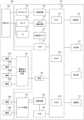
図1に本実施例に係る生体状態推定装置10の外観図を示す。図1(A)はベルト200を巻き付けた装着時の状態の外観を示し、図1(B)は、ベルト200を展開した状態の内周面202側からみた図である。 FIG. 1 shows an external view of a biological
生体状態推定装置10は、主として本体部100とベルト200を備える。ベルト200の外周面201に本体部100が設けられ、後述の制御部101等が収容されるとともに、外面には、表示部110及び操作部111が設けられる。ベルト200の内周面202には、長手方向の一端に面ファスナ210が設けられている。装着時に、この面ファスナ210と係合する他方の面ファスナは、ベルト200の外周面201に設けられている。ベルト200の内周面202の幅方向の一方の縁部202Aには心電波形測定用の電極群220A~220Fが長手方向に等間隔で配置されている。電極群220A~220Fから構成される心電センサ220は、上腕装着時には肩側となる縁部202Aに配置されている。ベルト200の内周面202の幅方向の他方の端部202Bには、脈波センサのセンサ部230を構成する電極231A、232A、232B、231Bが配置されている。電極231A及び電極231Bは上腕に通電するための電極であり、電極232A及び電極232Bは電圧を検出するための電極である。センサ部230は、上腕装着時には肘側となる位置に設けられている。センサ部230は、上腕装着時には上腕動脈に沿って、肩側から肘側へと順に電極231A、232A、232B、231Bと配置されている。 The biological
(生体状態推定装置の特徴)
本実施例に係る生体状態推定装置10では、上述の心電センサ220及び脈波センサのセンサ部230を通じて取得された心電波形(心電図)及び脈波波形(脈波信号)を探索し、心電波形の特徴量(心電特徴量)及び脈波波形の特徴量(脈波特徴量)を抽出し、心電特徴量及び脈波特徴量のうち少なくとも心電特徴量に基づいて、血圧値等の生体状態を推定する。心電図が心電特徴量を抽出可能な品質を有し、脈波信号が脈波特徴量を抽出可能な品質を有する場合には、それぞれを探索し、精度よく心電特徴量及び脈波特徴量を抽出することができるので、これらに基づく血圧値等の生体状態も精度よく推定することができる。(Features of biological state estimation device)
The biological
生体状態推定装置10の装着状態や、ユーザの体動、姿勢等によっては、心電図にノイズが重畳し、心電図の品質が低下する場合がある。このように品質が低い心電図だけから精度よく心電特徴量を抽出することは難しい。このとき、心電図に発生するノイズの原因によっては、心電図は影響を受けるものの脈波信号は影響を受けないか影響が小さい場合がある。図2は、このような心電図と脈波信号との関係を示すグラフである。ここでは、最上段が心電図、上から2段目が光電脈波センサによって検出された脈波信号、上から3
段目が圧力式脈波センサによって検出された脈波信号、最下段は加速度センサの出力信号(3軸方向の出力信号を実線、破線、点線で示している。)を示す。図2には、加速度センサの出力信号にも表れているように、縦方向の実線で示した時刻Tmを境とし、Tm以前には、生体状態推定装置10を装着したユーザの体動があり、Tm以降には体動がない状態で取得した波形が示されている。このため、最上段の心電図では、時刻Tm以前は筋電が重畳した波形となっているのに対して、Tm以降は筋電が重畳しない波形となっており、時刻Tmを境として心電図の波形が大きく異なっている。これに対して、いずれの脈波センサによる脈波信号にも、時刻Tmの前後で大きな変化は見られない。また、破線で示した期間Prdでは大きな体動が発生したために、心電図の波形は大きく乱れているのに対して、いずれの脈波信号にも乱れは見られない。Depending on the wearing state of the biological
The bottom row shows the pulse wave signal detected by the pressure-type pulse wave sensor, and the bottom row shows the output signal of the acceleration sensor (output signals in three axial directions are indicated by solid lines, broken lines, and dotted lines). As shown in the output signal of the acceleration sensor in FIG. 2 , there is body movement of the user wearing the biological
このような心電図と脈波信号の特性により、心電図が、心電図のみからは心電特徴量を抽出できないような品質を有する場合であっても、脈波信号が、脈波特徴量を抽出できる品質を有する場合には、後述するように、脈波特徴量を用いて、心電特徴量を抽出するための探索基準点を設定することが可能となる。よって、精度よく心電特徴量を抽出し、血圧値等の生体状態も精度よく推定することができる。 Due to such characteristics of the electrocardiogram and the pulse wave signal, even if the electrocardiogram has such a quality that the electrocardiographic feature cannot be extracted from the electrocardiogram alone, the pulse wave signal has a quality that allows the pulse wave feature to be extracted. , it is possible to set a search reference point for extracting an electrocardiographic feature using the pulse wave feature, as will be described later. Therefore, it is possible to accurately extract an electrocardiographic feature amount and accurately estimate a biological condition such as a blood pressure value.
(ハードウェア構成)
図3に本実施例に係る生体状態推定装置10のハードウェア構成図を示す。生体状態推定装置10は、主として、本体部100とベルト200を含んで構成される。(Hardware configuration)
FIG. 3 shows a hardware configuration diagram of the biological
上述のように、ベルト200の内周面には心電図を測定するための電極群220A~220Fが配置されている。
ベルト200の内周面には、脈波を測定するための脈波センサのセンサ部230が配置されている。センサ部230はユーザの身体に通電するための一対の電極231A及び231Bと、電圧を検出するための一対の電極232A及び232Bを含む。また、ベルト200には、センサ部230の電極231A及び231B間に通電するとともに電極232A及び232B間の電圧を検出する通電及び電圧検出回路233が設けられている。通電及び電圧検出回路233は、本体部100に設けてもよい。
また、ベルト200は、流体を貯留し得る袋状の押圧カフ204を含む。As described above, the inner circumferential surface of
A
Belt 200 also includes a bladder-
本体部100には、制御部101、記憶部102、電池103、スイッチ回路104、減算回路105、アナログフロントエンド(AFE)106、圧力センサ107、発振回路108、ポンプ109、表示部110、操作部111、弁112、ポンプ駆動回路113、加速度センサ114、AFE115、通信部116が設けられている。 The
制御部101は、CPU(Central Processing Unit)1011、RAM(Random Access Memory)1012、ROM(Read Only Memory)1013等を含み、各構成要素を制
御し、後述する種々の機能を実現する。記憶部102は、例えば、半導体メモリ、ハードディスクドライブ(HDD)等の補助記憶装置であり、制御部101で実行されるプログラム、プログラムを実行するために必要な設定データ、測定結果等を記憶する。プログラムの一部又は全部は、ROM1013に記憶されてもよい。The
電池103は、制御部101等に電力を供給する。電池103は、例えば、充電可能なバッテリによって構成することができる。 A
心電センサ220に含まれる各電極220A~220Fは、スイッチ回路104の入力端子に接続されている。スイッチ回路104の2つの出力端子はそれぞれ、減算回路105の2つの入力端子に接続されている。スイッチ回路104は、制御部101からのスイッチ信号を受け取り、スイッチ信号によって指定される2つの電極を減算回路105に接
続する。減算回路105は、一方の入力端子から入力された電位から他方の入力端子から入力される電位を減算する。減算回路105は接続された2つの電極間の電位差を表す電位差信号をAFE106へ出力する。減算回路105は、例えば、計装アンプである。AFE106は、例えば、ローパスフィルタ(LPF)、増幅器、及びアナログデジタル(AD)変換器を含む。電位差信号は、LPFで濾波され、増幅器で増幅され、AD変換器でデジタル信号に変換される。デジタル信号に変換された電位差信号は、制御部101に出力される。制御部101はAFE106から時系列で取得される電位差信号を心電図として取得する。Each
通電及び電圧検出回路233は、電極231A及び231B間に高周波定電流を流す。例えば、電流の周波数は50kHzであり、電流値は1mAである。通電及び電圧検出回路233は、電極231A及び231B間に通電した状態で、電極232A及び232B間の電圧を検出し、検出信号を生成する。検出信号は、電極232A及び232Bが対向する動脈の部分を伝播する脈波による電気インピーダンスの変化を表す。通電及び電圧検出回路233は、検出信号に対して整流、増幅、濾波及びAD変換を含む信号処理を行い、検出信号を制御部101に出力する。制御部101は、通電及び電圧検出回路233から時系列で出力される検出信号を脈波信号として取得する。 The energization and
加速度センサ114は、X,Y,Z方向の3軸の加速度を検出し、検出信号をAFE115へ出力する。AFE115は、例えば、増幅器及びAD変換器を含む。加速度センサ114の検出信号は、増幅器で増幅され、AD変換器でデジタル信号に変換される。デジタル信号に変換された検出信号は、制御部101に出力される。制御部101はAFE105から時系列で取得される検出信号を3軸の加速度信号として取得する。 The
圧力センサ107は配管を介して押圧カフ204に接続され、ポンプ109及び弁112は配管を介して押圧カフ204に接続される。配管は、共通の1つの配管であってもよい。ポンプ109は、例えば圧電ポンプであり、押圧カフ204の圧力を高めるために、配管を通して押圧カフ204に流体としての空気を供給する。弁112は、ポンプ109に搭載され、ポンプ109の動作状態に伴って開閉が制御される。弁112が開状態であるときは、押圧カフ204は大気と連通し、押圧カフ204内の空気が大気中に排出される。なお、弁112は、逆止弁の機能を有し、空気が逆流することがない。ポンプ駆動回路113は、制御部101から受け取る制御信号に基づいてポンプ109を駆動する。 The
圧力センサ107は、押圧カフ204内の圧力(カフ圧とも称する)を検出し、カフ圧を表す電気信号を生成する。カフ圧は、例えば、大気圧を基準とした圧力である。圧力センサ107は、例えばピエゾ抵抗式圧力センサである。発振回路108は、圧力センサ107からの電気信号に基づいて発振し、電気信号に応じた周波数を有する周波数信号を制御部に出力する。ここでは、圧力センサ107の出力は、押圧カフ204内の圧力を制御するために用いられるとともに、オシロメトリック法によって血圧値(収縮期血圧(最高血圧)及び拡張期血圧(最低血圧)を含む)を算出するために用いられる。
制御部101が1つのCPU1011を含む例について説明したが、制御部101の構成はこれに限られず、複数のプロセッサを含んでもよい。また、生体状態推定装置10は、ユーザの携帯端末(例えばスマートフォン)等の外部装置と通信するための通信部116を備えてもよい。通信方式は、有線及び/又は無線の適宜の方式を採用することができる。通信方式に応じて、通信部は有線通信モジュール及び/又は無線通信モジュールを含む。無線通信方式としては、例えば、Bluetooth(登録商標)、BLE(Bluetooth Low Energy)等を採用することができる。 Although an example in which control
操作部111は、ユーザが生体状態推定装置10に対して指示入力を行う入力装置であ
って、例えば、ボタン等により構成される。
表示部110は、測定結果やメッセージをユーザに表示するための表示装置であって、例えば、液晶表示装置(LCD)、OLED(Organic Light Emitting Diode)ディスプレイによって構成することができる。The
The
(ソフトウェア構成)
図4に、本実施例に係る生体状態推定装置のソフトウェア構成を示す。図4に示す、心電測定制御部101A、脈波測定制御部101B、加速度測定制御部101C、心電品質判定部101D、脈波品質判定部101E、脈波特徴量抽出部101F、脈波に基づく探索基準点設定部101G、心電図に基づく探索基準点設定部101H、心電特徴量抽出部101I、脈波伝播時間算出部101J、血圧値算出部101K、表示制御部101L、血圧測定制御部101M、指示入力部101N、校正部101P、エラー処理部101Qは、制御部101が記憶部192に記憶されたプログラムを実行することによって実現される。心電図記憶部102A、脈波記憶部102B、加速度記憶部102C、血圧値記憶部102E及び血圧値記憶部102Fは、記憶部102によって実現される。(software configuration)
FIG. 4 shows the software configuration of the biological state estimation device according to this embodiment. 4, the electrocardiogram
心電測定制御部101Aは、心電図を取得するためにスイッチ回路104を制御する。具体的には、心電測定制御部101Aは、6つの電極220A~220Fのうち2つの電極を選択するためのスイッチ信号を生成し、このスイッチ信号をスイッチ回路104に出力する。心電測定制御部101Aは、選択した2つの電極を用いて得られた電位差信号を取得し、取得された電位差信号の時系列データを心電図として心電図記憶部102Aに記憶させる。 The electrocardiogram
ユーザが生体状態推定装置10を上腕に装着した場合には、心電測定制御部101Aは、心電図を取得するのに最適な電極対を決定する。例えば、心電測定制御部101Aは、すべての電極対それぞれについて心電図を取得し、R波の振幅が最も大きい心電図を提供する電極対を最適な電極対として決定する。その後は、心電測定制御部101Aは、最適な電極対を用いて心電図を測定する。 When the user wears the biological
脈波測定制御部101Bは、脈波信号を取得するために通電及び電圧検出回路233を制御する。具体的には、脈波測定制御部101Bは、電極231A及び231B間に電流を流すように通電及び電圧検出回路233に指示し、電極231A及び231B間に電流を流した状態で検出された電極232A及び232B間の電圧を示す検出信号を取得する。脈波測定制御部101Bは、検出信号の時系列データを脈波信号として脈波記憶部102Bに記憶させる。 The pulse wave
加速度測定制御部101Cは、所定周期で、加速度センサ114が出力する3軸の加速度を取得し、加速度信号として加速度記憶部102Cに記憶させる。 The acceleration
心電品質判定部101Dは、心電図記憶部102Aに記憶された心電図が、心電図のみから心電特徴量を抽出可能な品質を有するか否かを判定する。心電図の品質の判定には、以下のような方法を用いることができる。例えば、心電波形が一定しているか等の基準に従って電極の接触状態の良否を判定することにより、心電図の品質を判定することができる。また、加速度記憶部102Cから3軸の加速度信号を取得し、加速度信号が所定の閾値以下であるか否かにより、心電図の品質を判定することもできる。また、筋電図の混入の有無により心電図の品質を判定することができる。心電図に筋電図が混入すると不規則な細かい振動がみられるので、このような不規則な細かい振動の有無を検出することにより、筋電図の混入の有無を判定することもできる。心電図の品質の判定は、上述の方法のいずれかを用いてもよいし、上述の方法のうちいずれか2つ又は3つあるいはすべての方法を用いてもよい。また、心電図の品質の判定はこれらに限られず、他の公知の方法を採
用することができる。The electrocardiogram
脈波品質判定部101Eは、脈波記憶部102Bに記憶された脈波信号が、脈波特徴量を抽出可能な品質を有するか否かを判定する。脈波信号の品質の判定には、以下の方法を用いることができる。例えば、脈波信号が一定しているか等の基準に従って電極の接触状態の良否を判定することにより、脈波信号の品質を判定することができる。また、加速度記憶部102Cから3軸の加速度信号を取得し、加速度信号が所定の閾値以下であるか否かにより、脈波信号の品質を判定することもできる。また、脈波記憶部102Bに記憶された脈波信号の1拍の振幅値が所定の閾値以下であるか否かにより、脈波信号の品質を判定することもできる。脈波信号の品質の判定は、上述の方法のいずれかを用いてもよいし、上述の方法のうちいずれか2つ又は3つあるいはすべての方法を用いてもよい。また、脈波信号の品質の判定はこれらに限られず、他の公知の方法を採用することができる。 The pulse wave
心電図に基づく探索基準点設定部101Hは、心電特徴量抽出部101Iが心電図の波形から特徴量を抽出する際に、心電図を探索するための基準点を設定する。例えば、R波に対応するピーク点を基準点とすることができる。基準点はこれに限らず、目的に応じて、Q波に対応するピーク点、S波に対するピーク点等を基準点としてもよい。 The electrocardiogram-based search reference
心電特徴量抽出部101Iは、上述のように、心電図に基づく探索基準点設定部101Hによって設定された基準点を心電図で探索し、心電特徴量を抽出する。心電特徴量としては、R波以外にも、P波、QRS波、T波、PQRST波、J波、PQ間隔、QT間隔、QRS時間等の種々の特徴量が対象となる。
図5に、心電図の品質が良好であり、心電図のみから心電特徴量を抽出可能な場合の例を示す。図5の上段は、心電図記憶部102Aから読み出した心電図の例を示し、図5の下段は、脈波記憶部102Bから読み出した脈波の例を示す。心電図の品質が良好であり、基準点として、R波に対応するピーク点が設定された場合には、心電波形を探索し、R波に対応するピーク点Wr1、Wr2、Wr3を検出し、その時刻を特定する。このように、心電特徴量としてR波に対応するピークの間隔として拍動時刻を抽出する。このようにして取得された拍動時刻に基づいて、生体状態としての心拍数を推定することができる。また、R波に対応するピーク点Wr1、Wr2、Wr3を基準として、矢印に示すように心電図を探索し、上述のような種々の心電特徴量を抽出することができる。
良好な心電図が取得できている区間では、心電図のみから、心電特徴量を抽出することができるが、場合によっては、この心電特徴量(ここでは、拍動時刻である、心電図のR波のピーク点の時刻)を基準として、脈波特徴量(例えば、脈波の立ち上がり)を探索してもよい。As described above, the electrocardiogram feature quantity extraction unit 101I searches the electrocardiogram for the reference point set by the electrocardiogram-based search reference
FIG. 5 shows an example in which the quality of the electrocardiogram is good and the electrocardiogram feature quantity can be extracted only from the electrocardiogram. The upper part of FIG. 5 shows an example of an electrocardiogram read from the
It is possible to extract an electrocardiogram feature quantity from only the electrocardiogram in a section where a good electrocardiogram can be acquired. A pulse wave characteristic amount (for example, the rising edge of a pulse wave) may be searched for based on the time of the peak point of .
脈波特徴量抽出部101Fは、心電品質判定部101Dにおいて、心電図が、心電図のみから心電特徴量を抽出可能な品質を有していないと判定された場合に、脈波特徴量を、脈波記憶部102Bに記憶された脈波から抽出し、引き続き脈波に基づく探索基準点設定部101Gが、心電図を探索するための基準点を設定する。脈波の拍出に関連する特徴量としては、脈波の立ち上がり、ボトム、ピークや、脈波の1次微分のピークや2次微分のピークを設定することができるが、これらに限られない。
図6は、心電図の品質が良好でなく、心電図が心電特徴量を抽出可能な品質を有しないが、脈波信号は脈波特徴量を抽出可能な品質を有すると判定された場合の心電図と脈波信号の例を示す。図6の上段は、心電図記憶部102Aから読み出した心電図の例を示し、図6の下段は、脈波記憶部102Bから読み出した脈波信号の例を示す。脈波特徴量抽出部101Fは、脈波記憶部102Bに記憶された脈波信号から、脈波特徴量である立ち上がり点Wp1、Wp2、Wp3を抽出し、その時刻を特定する。このようにして抽出された脈波特徴量のデータは、脈波に基づく探索基準点設定部101Gに与えられる。
また、脈波特徴量抽出部101Fは、後述する血圧値を推定するための脈波特徴量を抽
出する。When the electrocardiographic
FIG. 6 is an electrocardiogram when the quality of the electrocardiogram is not good and the electrocardiogram does not have the quality for extracting the electrocardiogram feature quantity, but the pulse wave signal is determined to have the quality for extracting the pulse wave feature quantity. and pulse wave signals. The upper part of FIG. 6 shows an example of an electrocardiogram read from the
Further, the pulse wave feature
脈波に基づく探索基準点設定部101Gは、このようにして抽出された脈波特徴量に基づいて心電図を探索するための基準点を設定する。脈波信号の立ち上がり点が抽出されると、脈波に基づく探索基準点設定部101Gは、脈波信号の立ち上がり点の時刻に対応する心電図時点を基準点として設定し、心電特徴量抽出部101Iに与える。心電特徴量抽出部101Iは、脈波特徴量抽出部101Fから受け取った脈波の特徴量に基づいて設定された探索基準点を基準として、心電の特徴量を探索する。上述のように、脈波特徴量として脈波信号の立ち上がり点Wp1、Wp2、Wp3とその時刻が抽出された場合には、心電特徴量抽出部101Iは、脈波信号の立ち上がり点を基準とし、この立ち上がり点の時刻から所定時間内の心電図を矢印で示すように探索することにより、心電特徴量、例えば、R波に対応するピーク点を検出することができる。 The pulse wave-based search reference point setting unit 101G sets a reference point for searching an electrocardiogram based on the pulse wave feature quantity thus extracted. When the rising point of the pulse wave signal is extracted, the pulse wave-based search reference point setting unit 101G sets the electrocardiographic time point corresponding to the time of the rising point of the pulse wave signal as a reference point, 101I. The electrocardiogram feature amount extraction unit 101I searches for an electrocardiogram feature amount based on a search reference point set based on the pulse wave feature amount received from the pulse wave feature
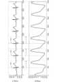
図7は、心電図が、心電図のみから心電特徴量を抽出可能な品質を有しないが、脈波信号は脈波特徴量を抽出可能な品質を有すると判定された場合の心電図と脈波信号の他の例を示す。ここでは、図7の上段が脈波記憶部102Bから読み出した脈波信号、下段が心電図記憶部102Aから読み出した心電図である。この例では、生体状態推定装置10を装着したユーザが椅子に座って腕を前に上げた状態で心電図及び脈波を測定した。片腕で心電図を測定する場合には、心電センサ220によって検出される心電波形自体が小さく(I誘導の1/10以下)かつ筋電の影響が大きく出ている。 FIG. 7 shows an electrocardiogram and a pulse wave signal when it is determined that the electrocardiogram does not have the quality that allows the electrocardiographic feature amount to be extracted from the electrocardiogram alone, but the pulse wave signal has the quality that allows the pulse wave feature amount to be extracted. shows another example of Here, the upper part of FIG. 7 is the pulse wave signal read from the pulse
図7に示す例では、脈波特徴量抽出部101Fは、脈波のピーク点Wp11、Wp12、Wp13、Wp14等を抽出する。
このようにして抽出された脈波信号のピーク点Wp11等のデータに基づいて、脈波に基づく探索基準点設定部101Gは、脈波信号のピーク点Wp11等の時刻を、心電図を探索する際の基準点として、心電特徴量抽出部101Iに与える。
心電特徴量抽出部101Iは、例えば、脈波信号のピーク点Wp11等の時刻を基準として、心電図を探索し、R波に対応するピーク点Wr11、Wr12、Wr13、Wr14等を抽出する。このように、心電図において、R波に対応するピーク点を抽出したとしても、図7に示すように、心電図として得られているのは、筋電が重畳した汚い波形であり、心電図のみから、R波に対応するピーク点を基準として、心電特徴量を抽出することが難しい。このため、上述のようにして抽出されたR波に対応するピーク点を基準として、図8(A)に示すような1拍毎の波形の同期加算平均をとると図8(B)に示すきれいな波形(同期加算平均波形)が得られる。図9(A)は、1拍毎の波形をグレーで示し、R波に対応するピーク点を基準として同期加算平均をとった同期加算平均波形を黒で示す。また、図9(B)は、比較のために示したI誘導によって測定した心電図の波形である。図9(B)に示す心電図の波形においてP波を明確に抽出できるように、図9(A)に示す同期加算平均による心電図波形においてもP波を明確に抽出できるので、他の心電の特徴についても同様に抽出することができる。In the example shown in FIG. 7, the pulse wave feature
Based on the data such as the peak point Wp11 of the pulse wave signal extracted in this manner, the pulse wave-based search reference point setting unit 101G sets the time of the peak point Wp11 of the pulse wave signal, etc. when searching for the electrocardiogram. , is given to the electrocardiogram feature quantity extraction unit 101I as a reference point of .
For example, the electrocardiogram feature amount extraction unit 101I searches the electrocardiogram based on the time of the peak point Wp11 of the pulse wave signal, and extracts the peak points Wr11, Wr12, Wr13, Wr14, etc. corresponding to the R wave. In this way, even if the peak point corresponding to the R wave is extracted from the electrocardiogram, as shown in FIG. It is difficult to extract an electrocardiogram feature quantity with reference to the peak point corresponding to the R wave. For this reason, taking the peak point corresponding to the R wave extracted as described above as a reference, synchronous addition and averaging of the waveform for each beat as shown in FIG. 8(A) is shown in FIG. 8(B). A clean waveform (synchronous averaging waveform) can be obtained. FIG. 9A shows the waveform for each beat in gray, and shows the synchronous averaging waveform obtained by taking the synchronous averaging with reference to the peak point corresponding to the R wave in black. FIG. 9B is an electrocardiogram waveform measured by lead I shown for comparison. As the P wave can be clearly extracted from the electrocardiogram waveform shown in FIG. Features can be similarly extracted.
脈波伝播時間算出部101Jは、心電特徴量抽出部101Iと脈波特徴量抽出部101Fから取得される心電図の特徴点と脈波信号の特徴点との間の時間差に基づいて脈波伝播時間を算出する。例えば、脈波伝播時間算出部101Jは、心電図からR波に対応するピーク点の時刻を検出し、脈波信号から立ち上がり点の時刻を検出し、立ち上がり点の時刻からピーク点の時刻を引いた差を脈波伝播時間として算出する。 The pulse wave propagation
血圧値算出部101Kは、脈波伝播時間算出部101Jにより算出された脈波伝播時間と、脈波伝播時間から血圧値を算出する算出式とに基づいて血圧値を算出する。脈波伝播時間から血圧値を算出するための算出式としては、公知の算出式を適宜採用することができるので、説明は省略する。血圧値算出部101Kによって算出された血圧値は、血圧値
記憶部102Eに記憶される。The blood pressure value calculator 101K calculates the blood pressure value based on the pulse wave transit time calculated by the pulse wave
指示入力部101Nは、操作部111を用いてユーザから入力された指示を受け付ける。例えば、ユーザが血圧測定の実行を指示する操作を行うと、指示入力部101Nは、血圧測定制御部101Mに、血圧測定の開始指示を与える。
血圧測定制御部101Mは、血圧測定を実行するためにポンプ駆動回路113を制御する。血圧測定制御部101Mは、指示入力部101Nから血圧測定の開始指示を受けると、ポンプ駆動回路113を介してポンプ109を駆動する。これにより、押圧カフ204への空気の供給が開始される。押圧カフ204が膨張し、ユーザの上腕が圧迫される。血圧測定制御部101Mは、圧力センサ107を用いてカフ圧を監視する。血圧測定制御部101Mは、押圧カフ204に空気を供給する加圧過程において、圧力センサ107から出力される圧力信号に基づいて、オシロメトリック法により血圧値を算出する。血圧値は、収縮期血圧(SBP)及び拡張期血圧(DBP)を含むが、これに限定されない。血圧測定制御部101Mは、算出した血圧値を時間情報に関連付けて血圧値記憶部102Fに記憶させる。血圧測定制御部101Mは、血圧値と同時に心拍数を算出することができる。血圧測定制御部101Mは、血圧値の算出が完了すると、ポンプ駆動回路113を介してポンプ109を停止する。これにより、押圧カフ204から弁を通じて空気が排出される。血圧測定制御部は、所定カフ圧まで加圧された押圧カフ204から空気を排出する減圧過程において、オシロメトリック法による血圧値を算出してもよい。 The blood pressure
表示制御部101Lは、表示部110を制御し、ユーザに対するメッセージや、血圧値、心拍数等の測定結果を表示部に表示させる。 The
校正部101Pは、脈波伝播時間算出部101Jにより得られた脈波伝播時間と、血圧測定制御部101Mによって得られた血圧値とに基づいて、血圧算出式の校正を行う。脈波伝播時間と血圧値との対応関係は、ユーザ個人によっても異なり、生体状態推定装置10の装着位置によっても異なる。このため、血圧算出式の校正を行う。血圧算出式の校正方法としては、公知の方法を採用することができるので説明を省略する。 The
エラー処理部101Qは、心電品質判定部101Dにおいて、心電図が心電図のみから心電特徴量を抽出可能な品質を有しないと判定され、さらに、脈波品質判定部101Eにおいて、脈波信号が脈波特徴量を抽出可能な品質を有しないと判定された場合に、エラーと判定し、血圧値等の生体状態推定処理を終了する。そして、エラー処理部101Qは、表示制御部101Lにより、エラーとなった旨やメッセージを表示部110に表示させる。 In the
また、心電図及び脈波信号の品質を判定するには、心電図と脈波信号に限らず、加速度センサ114によって検出される加速度を用いることもできる。 Further, the quality of the electrocardiogram and pulse wave signals is not limited to the electrocardiogram and pulse wave signals, and the acceleration detected by the
本実施例に係る生体状態推定装置10は、上述のように、心電図が、心電図のみから心電特徴量を抽出可能な品質を有する場合には、心電特徴量を抽出するために心電図を探索するための探索基準点を心電図に基づいて設定するが、心電図が、心電図のみから心電特徴量を抽出可能でない品質を有する場合には、脈波センサのセンサ部230によって検出された脈波特徴量を抽出することにより、心電図を探索するための探索基準点を設定する。このように、脈波特徴量に基づいて心電図を探索するので、心電図に影響しやすいが脈波信号には影響しにくいノイズが存在する場合にも、精度よく新特徴量を抽出することができ、さらには、精度よく血圧値等の生体状態を推定することができる。 As described above, the biological
ここでは、電極231A、231B、232A及び232Bを含むセンサ部230と、
通電及び電圧検出回路233と、脈波測定制御部101Bとして機能する制御部101が、本発明の脈波波形取得部に相当する。また、電極群230A~230Fと、スイッチ回路104と、減算回路105と、AFE106と、心電測定制御部101Aとして機能する制御部101が、本発明の心電波形取得部に相当する。心電品質判定部101Dとして機能する制御部101が、本発明の心電波形品質判定部に相当する。脈波品質判定部101Eとして機能する制御部101が、本発明の脈波波形品質判定部に相当する。脈波に基づく探索基準点設定部101Gとして機能する制御部101が、本発明の第2探索基準点設定部に相当し、脈波に基づく探索基準点設定部101Gによって設定される心電図探索の基準点が本発明の第2基準点に相当する。心電に基づく探索基準点設定部101Hとして機能する制御部101が、本発明の第1探索基準点設定部に相当し、心電に基づく探索基準点設定部101Hによって設定される心電図探索の基準点が本発明の第1基準点に相当する。Here, a
The energization and
(心電特徴量抽出方法)
図10は、本実施例に係る生体状態推定装置10において、心電特徴量を抽出する動作を説明するフローチャートである。(Electrocardiogram feature value extraction method)
FIG. 10 is a flowchart for explaining the operation of extracting an electrocardiographic feature amount in the biological
制御部101は、心電図、脈波波形及び加速度を測定し、記憶部102に記憶しているものとして、以降の動作について説明する。 It is assumed that the
まず、ステップS1において、心電図の品質が良好か否か、すなわち、心電図のみに基づいて心電特徴量を抽出可能な品質を有するか否かを判定する。 First, in step S1, it is determined whether or not the quality of the electrocardiogram is good, that is, whether or not the quality is such that the electrocardiographic feature quantity can be extracted based on only the electrocardiogram.
ステップS1において、心電図の品質が良好であると判定された場合には、ステップS2に進む。
ステップS2では、心電図においてR波のピーク点を探索し、これを探索基準点に設定し、ステップS3に進む。If it is determined in step S1 that the quality of the electrocardiogram is good, the process proceeds to step S2.
In step S2, the peak point of the R wave is searched for in the electrocardiogram and set as the search reference point, and the process proceeds to step S3.
ステップS1において、心電図の品質が良好でないと判定された場合には、ステップS4に進む。
ステップS4では、脈波信号の品質が良好か否か、すなわち、脈波信号に基づいて脈波特徴量を抽出可能な品質を有するか否かを判定する。If it is determined in step S1 that the quality of the electrocardiogram is not good, the process proceeds to step S4.
In step S4, it is determined whether or not the quality of the pulse wave signal is good, that is, whether or not the pulse wave feature quantity can be extracted based on the pulse wave signal.
ステップS4において、脈波信号の品質が良好であると判定された場合には、ステップS5に進む。
ステップS5では、脈波の特徴量を抽出し、これを探索基準点に設定する。例えば、脈波の立ち上がりを抽出し、この脈波の立ち上がり点の時刻を探索基準点に設定し、ステップS3に進む。If it is determined in step S4 that the quality of the pulse wave signal is good, the process proceeds to step S5.
In step S5, the pulse wave feature quantity is extracted and set as a search reference point. For example, the rise of the pulse wave is extracted, the time of the rise point of this pulse wave is set as the search reference point, and the process proceeds to step S3.
そして、ステップS3では、ステップS2又はステップS5において設定された探索基準点を用いて心電特徴量を抽出する。 Then, in step S3, an electrocardiographic feature amount is extracted using the search reference points set in step S2 or step S5.
ステップS4において、脈波信号の品質が良好でないと判定された場合には、エラーと判定し、処理を終了する。エラーと判定された場合のエラー処理としては、例えば、エラーとなった旨を表示部に表示し、ユーザに報知してもよい。エラーの原因に応じて、ベルトを装着し直す、正しい測定姿勢をとる等のメッセージを表示部110に表示するようにしてもよい。 If it is determined in step S4 that the quality of the pulse wave signal is not good, it is determined as an error, and the process ends. As error processing when it is determined that an error has occurred, for example, the fact that an error has occurred may be displayed on the display unit to notify the user. Depending on the cause of the error, the
10・・・生体状態推定装置
101・・制御部
104・・スイッチ回路
105・・減算回路
106・・AFE
220・・心電センサ
230・・脈波センサ
233・・通電及び電圧検出回路
DESCRIPTION OF
220...
Claims (10)
Translated fromJapanese前記心電波形を探索して該心電波形の特徴量を抽出する心電特徴量抽出部と、
脈波波形を取得する脈波波形取得部と、
前記脈波波形を探索して該脈波波形の特徴量を抽出する脈波特徴量抽出部と、
を備え、前記心電波形の特徴量及び前記脈波波形の特徴量のうち少なくとも該心電波形の特徴量に基づいて生体状態を推定する生体状態推定装置であって、
前記心電波形が、該心電波形のみから心電波形の特徴量を抽出可能な品質を有するか否かを判定する心電波形品質判定部と、
前記心電波形が該心電波形の特徴量を抽出可能な品質を有すると判定された場合に、前記心電波形を探索するための第1基準点を設定する第1探索基準点設定部と、
前記心電波形が該心電波形の特徴量を抽出可能な品質を有しないと判定された場合に、前記脈波波形の特徴量に基づいて、前記心電波形を探索するための第2基準点を設定する第2探索基準点設定部と、
を備え、
前記心電特徴量抽出部は、前記第1基準点又は前記第2基準点に基づいて前記心電波形を探索して前記心電波形の特徴量を抽出することを特徴とする生体状態推定装置。an electrocardiographic waveform acquisition unit that acquires an electrocardiographic waveform;
an electrocardiogram feature amount extraction unit that searches for the electrocardiogram waveform and extracts a feature amount of the electrocardiogram waveform;
a pulse waveform acquisition unit that acquires a pulse waveform;
a pulse wave feature amount extraction unit that searches for the pulse wave waveform and extracts a feature amount of the pulse wave waveform;
A biological state estimation device for estimating a biological state based on at least the feature amount of the electrocardiographic waveform among the feature amount of the electrocardiogram waveform and the feature amount of the pulse wave waveform,
an electrocardiographic waveform quality determination unit that determines whether or not the electrocardiographic waveform has a quality that enables extraction of a feature quantity of the electrocardiographic waveform only from the electrocardiographic waveform;
a first search reference point setting unit for setting a first reference point for searching for the electrocardiogram waveform when the electrocardiogram waveform is determined to have a quality that enables extraction of a feature quantity of the electrocardiogram waveform; ,
A second criterion for searching for the electrocardiographic waveform based on the feature quantity of the pulse waveform when it is determined that the electrocardiographic waveform does not have a quality that allows extraction of the feature quantity of the electrocardiographic waveform a second search reference point setting unit that sets a point;
with
The biological state estimating apparatus, wherein the electrocardiogram feature amount extraction unit searches for the electrocardiogram waveform based on the first reference point or the second reference point and extracts the feature amount of the electrocardiogram waveform. .
前記脈波波形が該脈波波形の特徴量を抽出可能な品質を有すると判定された場合に、前記脈波特徴量抽出部が前記脈波波形の特徴量を抽出することを特徴とする請求項1に記載の生体状態推定装置。A pulse waveform quality determination unit that determines whether the pulse waveform has a quality that allows extraction of the feature amount of the pulse waveform,
The pulse wave feature amount extracting unit extracts the feature amount of the pulse wave waveform when it is determined that the pulse wave waveform has a quality that enables extraction of the feature amount of the pulse wave waveform. Item 2. The biological state estimation device according to item 1.
前記第2探索基準点設定部は、前記脈波波形の立ち上がりの時刻を前記第2基準点として設定することを特徴とする請求項1又は2に記載の生体状態推定装置。The pulse wave feature quantity extraction unit extracts the rise of the pulse wave waveform,
3. The biological state estimation apparatus according to claim 1, wherein the second search reference point setting unit sets a rise time of the pulse waveform as the second reference point.
前記第2探索基準点設定部は、前記脈波波形のピークの時刻を前記第2基準点として設定することを特徴とする請求項1又は2に記載の生体状態推定装置。The pulse wave feature amount extraction unit extracts the peak of the pulse wave waveform,
3. The biological state estimation apparatus according to claim 1, wherein the second search reference point setting unit sets a peak time of the pulse waveform as the second reference point.
前記第2探索基準点設定部は、前記脈波波形から算出された1次微分波形におけるピークの時刻を前記第2基準点として設定することを特徴とする請求項1又は2に記載の生体状態推定装置。The pulse wave feature amount extraction unit extracts a peak in a first-order differential waveform calculated from the pulse wave waveform,
3. The biological condition according to claim 1, wherein the second search reference point setting unit sets a peak time in the first-order differential waveform calculated from the pulse waveform as the second reference point. estimation device.
前記第2探索基準点設定部は、前記脈波波形から算出された2次微分波形におけるピークの時刻を前記第2基準点として設定することを特徴とする請求項1又は2に記載の生体状態推定装置。The pulse wave feature amount extraction unit extracts a peak in the second derivative waveform calculated from the pulse wave waveform,
3. The biological condition according to claim 1 or 2, wherein the second search reference point setting unit sets a peak time in a second derivative waveform calculated from the pulse waveform as the second reference point. estimation device.
前記同期加算平均波形を前記表示部に表示させることを特徴とする請求項7に記載の生体状態推定装置。Equipped with a display for displaying information,
8. The biological state estimation apparatus according to claim 7, wherein the synchronous addition average waveform is displayed on the display unit.
9. The biological state estimation device according to claim 1, wherein a heart rate is estimated as the biological state.
Priority Applications (5)
| Application Number | Priority Date | Filing Date | Title |
|---|---|---|---|
| JP2021142288AJP7666248B2 (en) | 2021-09-01 | 2021-09-01 | Biological condition estimation device |
| DE112022004218.4TDE112022004218T5 (en) | 2021-09-01 | 2022-08-23 | Biological status assessment device |
| CN202280056184.6ACN117835898A (en) | 2021-09-01 | 2022-08-23 | Biological state estimation device |
| PCT/JP2022/031743WO2023032760A1 (en) | 2021-09-01 | 2022-08-23 | Biological state estimation device |
| US18/582,237US20240188874A1 (en) | 2021-09-01 | 2024-02-20 | Biological state estimation device |
Applications Claiming Priority (1)
| Application Number | Priority Date | Filing Date | Title |
|---|---|---|---|
| JP2021142288AJP7666248B2 (en) | 2021-09-01 | 2021-09-01 | Biological condition estimation device |
Publications (3)
| Publication Number | Publication Date |
|---|---|
| JP2023035439Atrue JP2023035439A (en) | 2023-03-13 |
| JP2023035439A5 JP2023035439A5 (en) | 2024-09-04 |
| JP7666248B2 JP7666248B2 (en) | 2025-04-22 |
Family
ID=85412506
Family Applications (1)
| Application Number | Title | Priority Date | Filing Date |
|---|---|---|---|
| JP2021142288AActiveJP7666248B2 (en) | 2021-09-01 | 2021-09-01 | Biological condition estimation device |
Country Status (5)
| Country | Link |
|---|---|
| US (1) | US20240188874A1 (en) |
| JP (1) | JP7666248B2 (en) |
| CN (1) | CN117835898A (en) |
| DE (1) | DE112022004218T5 (en) |
| WO (1) | WO2023032760A1 (en) |
Cited By (1)
| Publication number | Priority date | Publication date | Assignee | Title |
|---|---|---|---|---|
| WO2024190340A1 (en)* | 2023-03-15 | 2024-09-19 | オムロン株式会社 | Biological signal measurement device and method for controlling biological signal measurement device |
Families Citing this family (1)
| Publication number | Priority date | Publication date | Assignee | Title |
|---|---|---|---|---|
| EP4289358B1 (en)* | 2022-06-10 | 2024-12-11 | Tata Consultancy Services Limited | Estimating blood pressure of a subject using an ecg driven cardiovascular model |
Citations (5)
| Publication number | Priority date | Publication date | Assignee | Title |
|---|---|---|---|---|
| JP2012071018A (en)* | 2010-09-29 | 2012-04-12 | Denso Corp | Pulse wave analyzer and blood pressure estimator |
| WO2015163369A1 (en)* | 2014-04-25 | 2015-10-29 | 株式会社東芝 | Electrocardiographic waveform detection device and imaging device |
| WO2016031179A1 (en)* | 2014-08-27 | 2016-03-03 | セイコーエプソン株式会社 | Biological information detection device |
| US20200093389A1 (en)* | 2018-09-24 | 2020-03-26 | Sotera Wireless, Inc. | Method and system for monitoring a patient for atrial fibrillation and/or asystole |
| JP2020199022A (en)* | 2019-06-07 | 2020-12-17 | 株式会社デンソー | State estimation device, state estimation system, and state estimation method |
Family Cites Families (6)
| Publication number | Priority date | Publication date | Assignee | Title |
|---|---|---|---|---|
| JP5038222B2 (en) | 2008-04-21 | 2012-10-03 | 株式会社デンソー | Biological state estimation device, program, and recording medium |
| JP5521906B2 (en)* | 2010-08-30 | 2014-06-18 | 株式会社デンソー | Blood pressure estimation device |
| US11712190B2 (en)* | 2015-06-12 | 2023-08-01 | ChroniSense Medical Ltd. | Wearable device electrocardiogram |
| WO2017068751A1 (en)* | 2015-10-21 | 2017-04-27 | 日本電気株式会社 | Electrocardiogram measurement apparatus and electrocardiogram measurement method |
| US10485433B2 (en)* | 2016-12-29 | 2019-11-26 | Intel Corporation | Reliable estimation of pulse transit time in motion for cuffless blood pressure estimation |
| KR102847308B1 (en)* | 2019-03-20 | 2025-08-18 | 삼성전자주식회사 | the Electronic Device measuring the Blood Pressure and the Method for measuring the Blood Pressure |
- 2021
- 2021-09-01JPJP2021142288Apatent/JP7666248B2/enactiveActive
- 2022
- 2022-08-23WOPCT/JP2022/031743patent/WO2023032760A1/ennot_activeCeased
- 2022-08-23DEDE112022004218.4Tpatent/DE112022004218T5/enactivePending
- 2022-08-23CNCN202280056184.6Apatent/CN117835898A/enactivePending
- 2024
- 2024-02-20USUS18/582,237patent/US20240188874A1/enactivePending
Patent Citations (5)
| Publication number | Priority date | Publication date | Assignee | Title |
|---|---|---|---|---|
| JP2012071018A (en)* | 2010-09-29 | 2012-04-12 | Denso Corp | Pulse wave analyzer and blood pressure estimator |
| WO2015163369A1 (en)* | 2014-04-25 | 2015-10-29 | 株式会社東芝 | Electrocardiographic waveform detection device and imaging device |
| WO2016031179A1 (en)* | 2014-08-27 | 2016-03-03 | セイコーエプソン株式会社 | Biological information detection device |
| US20200093389A1 (en)* | 2018-09-24 | 2020-03-26 | Sotera Wireless, Inc. | Method and system for monitoring a patient for atrial fibrillation and/or asystole |
| JP2020199022A (en)* | 2019-06-07 | 2020-12-17 | 株式会社デンソー | State estimation device, state estimation system, and state estimation method |
Cited By (1)
| Publication number | Priority date | Publication date | Assignee | Title |
|---|---|---|---|---|
| WO2024190340A1 (en)* | 2023-03-15 | 2024-09-19 | オムロン株式会社 | Biological signal measurement device and method for controlling biological signal measurement device |
Also Published As
| Publication number | Publication date |
|---|---|
| JP7666248B2 (en) | 2025-04-22 |
| CN117835898A (en) | 2024-04-05 |
| WO2023032760A1 (en) | 2023-03-09 |
| US20240188874A1 (en) | 2024-06-13 |
| DE112022004218T5 (en) | 2024-08-01 |
Similar Documents
| Publication | Publication Date | Title |
|---|---|---|
| US20180263518A1 (en) | Pulse wave transit time measurement device and living body state estimation device | |
| JP7136629B2 (en) | Pulse wave transit time measuring device and blood pressure measuring device | |
| US20240188874A1 (en) | Biological state estimation device | |
| US10537254B2 (en) | Blood pressure calculation method based on pulse return wave transmission time, and blood pressure monitor | |
| US12171530B2 (en) | Pulse transit time measuring apparatus and blood pressure measuring apparatus | |
| EP3203899B1 (en) | Non-invasive blood pressure monitors, methods and computer program product of operating the same | |
| US20210177274A1 (en) | Measurement device | |
| KR102158498B1 (en) | piezo-electric based blood pressure measuring apparatus using piezo-electric pulse device | |
| US20210127993A1 (en) | Pulse transit time measurement device and blood pressure measurement device | |
| JP6339178B2 (en) | Blood pressure measuring device | |
| CN102860822A (en) | Wrist electrocardio blood pressure measurement device | |
| JP2018042606A (en) | Blood pressure measuring device, and control method and program of blood pressure measuring device | |
| Atef et al. | PTT based continuous time non-invasive blood pressure system | |
| KR20100005689A (en) | Blood pressure measuring device using belt type sensor and cuff | |
| US12414697B2 (en) | Single-arm two-electrode blood pressure measuring device and measuring method thereof | |
| KR20130110304A (en) | Blood pressure measuring apparatus for measuring electrocardiogram | |
| JP2023035439A5 (en) | ||
| CN112190242A (en) | Wearable device and heart rate parameter detection method | |
| WO2021019059A1 (en) | Apparatus for use with a wearable cuff in measuring blood pressure | |
| JP2023121706A (en) | Neck-mounted type wearable device, and biological information measurement system using the same | |
| WO2023106295A1 (en) | Blood-pressure-measuring device and blood-pressure-measuring system | |
| JP2023070007A (en) | Biological information measurement device | |
| JP2016019697A (en) | Central blood pressure measurement device and central blood pressure measurement method | |
| CN120813302A (en) | Biological signal measuring device and control method for biological signal measuring device |
Legal Events
| Date | Code | Title | Description |
|---|---|---|---|
| A521 | Request for written amendment filed | Free format text:JAPANESE INTERMEDIATE CODE: A523 Effective date:20240827 | |
| A621 | Written request for application examination | Free format text:JAPANESE INTERMEDIATE CODE: A621 Effective date:20240827 | |
| TRDD | Decision of grant or rejection written | ||
| A01 | Written decision to grant a patent or to grant a registration (utility model) | Free format text:JAPANESE INTERMEDIATE CODE: A01 Effective date:20250311 | |
| A61 | First payment of annual fees (during grant procedure) | Free format text:JAPANESE INTERMEDIATE CODE: A61 Effective date:20250324 | |
| R150 | Certificate of patent or registration of utility model | Ref document number:7666248 Country of ref document:JP Free format text:JAPANESE INTERMEDIATE CODE: R150 |