JP2023022315A - Electrosurgical network - Google Patents
Electrosurgical networkDownload PDFInfo
- Publication number
- JP2023022315A JP2023022315AJP2022197054AJP2022197054AJP2023022315AJP 2023022315 AJP2023022315 AJP 2023022315AJP 2022197054 AJP2022197054 AJP 2022197054AJP 2022197054 AJP2022197054 AJP 2022197054AJP 2023022315 AJP2023022315 AJP 2023022315A
- Authority
- JP
- Japan
- Prior art keywords
- electrosurgical
- channel
- unit
- connection unit
- output port
- Prior art date
- Legal status (The legal status is an assumption and is not a legal conclusion. Google has not performed a legal analysis and makes no representation as to the accuracy of the status listed.)
- Pending
Links
Images


Classifications
- A—HUMAN NECESSITIES
- A61—MEDICAL OR VETERINARY SCIENCE; HYGIENE
- A61B—DIAGNOSIS; SURGERY; IDENTIFICATION
- A61B18/00—Surgical instruments, devices or methods for transferring non-mechanical forms of energy to or from the body
- A61B18/04—Surgical instruments, devices or methods for transferring non-mechanical forms of energy to or from the body by heating
- A61B18/12—Surgical instruments, devices or methods for transferring non-mechanical forms of energy to or from the body by heating by passing a current through the tissue to be heated, e.g. high-frequency current
- A61B18/1206—Generators therefor
- A—HUMAN NECESSITIES
- A61—MEDICAL OR VETERINARY SCIENCE; HYGIENE
- A61B—DIAGNOSIS; SURGERY; IDENTIFICATION
- A61B18/00—Surgical instruments, devices or methods for transferring non-mechanical forms of energy to or from the body
- A61B18/04—Surgical instruments, devices or methods for transferring non-mechanical forms of energy to or from the body by heating
- A61B18/12—Surgical instruments, devices or methods for transferring non-mechanical forms of energy to or from the body by heating by passing a current through the tissue to be heated, e.g. high-frequency current
- A61B18/14—Probes or electrodes therefor
- A61B18/1442—Probes having pivoting end effectors, e.g. forceps
- A61B18/1445—Probes having pivoting end effectors, e.g. forceps at the distal end of a shaft, e.g. forceps or scissors at the end of a rigid rod
- A—HUMAN NECESSITIES
- A61—MEDICAL OR VETERINARY SCIENCE; HYGIENE
- A61B—DIAGNOSIS; SURGERY; IDENTIFICATION
- A61B34/00—Computer-aided surgery; Manipulators or robots specially adapted for use in surgery
- A61B34/30—Surgical robots
- A—HUMAN NECESSITIES
- A61—MEDICAL OR VETERINARY SCIENCE; HYGIENE
- A61B—DIAGNOSIS; SURGERY; IDENTIFICATION
- A61B34/00—Computer-aided surgery; Manipulators or robots specially adapted for use in surgery
- A61B34/70—Manipulators specially adapted for use in surgery
- A—HUMAN NECESSITIES
- A61—MEDICAL OR VETERINARY SCIENCE; HYGIENE
- A61B—DIAGNOSIS; SURGERY; IDENTIFICATION
- A61B90/00—Instruments, implements or accessories specially adapted for surgery or diagnosis and not covered by any of the groups A61B1/00 - A61B50/00, e.g. for luxation treatment or for protecting wound edges
- A61B90/90—Identification means for patients or instruments, e.g. tags
- A61B90/98—Identification means for patients or instruments, e.g. tags using electromagnetic means, e.g. transponders
- A—HUMAN NECESSITIES
- A61—MEDICAL OR VETERINARY SCIENCE; HYGIENE
- A61B—DIAGNOSIS; SURGERY; IDENTIFICATION
- A61B18/00—Surgical instruments, devices or methods for transferring non-mechanical forms of energy to or from the body
- A61B18/04—Surgical instruments, devices or methods for transferring non-mechanical forms of energy to or from the body by heating
- A61B18/12—Surgical instruments, devices or methods for transferring non-mechanical forms of energy to or from the body by heating by passing a current through the tissue to be heated, e.g. high-frequency current
- A61B18/14—Probes or electrodes therefor
- A61B18/16—Indifferent or passive electrodes for grounding
- A—HUMAN NECESSITIES
- A61—MEDICAL OR VETERINARY SCIENCE; HYGIENE
- A61B—DIAGNOSIS; SURGERY; IDENTIFICATION
- A61B17/00—Surgical instruments, devices or methods
- A61B2017/00017—Electrical control of surgical instruments
- A61B2017/00022—Sensing or detecting at the treatment site
- A61B2017/00039—Electric or electromagnetic phenomena other than conductivity, e.g. capacity, inductivity, Hall effect
- A—HUMAN NECESSITIES
- A61—MEDICAL OR VETERINARY SCIENCE; HYGIENE
- A61B—DIAGNOSIS; SURGERY; IDENTIFICATION
- A61B17/00—Surgical instruments, devices or methods
- A61B2017/00017—Electrical control of surgical instruments
- A61B2017/00022—Sensing or detecting at the treatment site
- A61B2017/00057—Light
- A—HUMAN NECESSITIES
- A61—MEDICAL OR VETERINARY SCIENCE; HYGIENE
- A61B—DIAGNOSIS; SURGERY; IDENTIFICATION
- A61B17/00—Surgical instruments, devices or methods
- A61B2017/00017—Electrical control of surgical instruments
- A61B2017/00137—Details of operation mode
- A—HUMAN NECESSITIES
- A61—MEDICAL OR VETERINARY SCIENCE; HYGIENE
- A61B—DIAGNOSIS; SURGERY; IDENTIFICATION
- A61B17/00—Surgical instruments, devices or methods
- A61B2017/00017—Electrical control of surgical instruments
- A61B2017/00221—Electrical control of surgical instruments with wireless transmission of data, e.g. by infrared radiation or radiowaves
- A—HUMAN NECESSITIES
- A61—MEDICAL OR VETERINARY SCIENCE; HYGIENE
- A61B—DIAGNOSIS; SURGERY; IDENTIFICATION
- A61B17/00—Surgical instruments, devices or methods
- A61B2017/00367—Details of actuation of instruments, e.g. relations between pushing buttons, or the like, and activation of the tool, working tip, or the like
- A61B2017/00371—Multiple actuation, e.g. pushing of two buttons, or two working tips becoming operational
- A61B2017/00384—Actuation of one tool by pushing two buttons simultaneously
- A—HUMAN NECESSITIES
- A61—MEDICAL OR VETERINARY SCIENCE; HYGIENE
- A61B—DIAGNOSIS; SURGERY; IDENTIFICATION
- A61B17/00—Surgical instruments, devices or methods
- A61B2017/00477—Coupling
- A—HUMAN NECESSITIES
- A61—MEDICAL OR VETERINARY SCIENCE; HYGIENE
- A61B—DIAGNOSIS; SURGERY; IDENTIFICATION
- A61B17/00—Surgical instruments, devices or methods
- A61B2017/00973—Surgical instruments, devices or methods pedal-operated
- A—HUMAN NECESSITIES
- A61—MEDICAL OR VETERINARY SCIENCE; HYGIENE
- A61B—DIAGNOSIS; SURGERY; IDENTIFICATION
- A61B18/00—Surgical instruments, devices or methods for transferring non-mechanical forms of energy to or from the body
- A61B2018/00053—Mechanical features of the instrument of device
- A61B2018/00172—Connectors and adapters therefor
- A61B2018/00178—Electrical connectors
- A—HUMAN NECESSITIES
- A61—MEDICAL OR VETERINARY SCIENCE; HYGIENE
- A61B—DIAGNOSIS; SURGERY; IDENTIFICATION
- A61B18/00—Surgical instruments, devices or methods for transferring non-mechanical forms of energy to or from the body
- A61B2018/00571—Surgical instruments, devices or methods for transferring non-mechanical forms of energy to or from the body for achieving a particular surgical effect
- A61B2018/00589—Coagulation
- A—HUMAN NECESSITIES
- A61—MEDICAL OR VETERINARY SCIENCE; HYGIENE
- A61B—DIAGNOSIS; SURGERY; IDENTIFICATION
- A61B18/00—Surgical instruments, devices or methods for transferring non-mechanical forms of energy to or from the body
- A61B2018/00571—Surgical instruments, devices or methods for transferring non-mechanical forms of energy to or from the body for achieving a particular surgical effect
- A61B2018/00601—Cutting
- A—HUMAN NECESSITIES
- A61—MEDICAL OR VETERINARY SCIENCE; HYGIENE
- A61B—DIAGNOSIS; SURGERY; IDENTIFICATION
- A61B18/00—Surgical instruments, devices or methods for transferring non-mechanical forms of energy to or from the body
- A61B2018/00571—Surgical instruments, devices or methods for transferring non-mechanical forms of energy to or from the body for achieving a particular surgical effect
- A61B2018/00607—Coagulation and cutting with the same instrument
- A—HUMAN NECESSITIES
- A61—MEDICAL OR VETERINARY SCIENCE; HYGIENE
- A61B—DIAGNOSIS; SURGERY; IDENTIFICATION
- A61B18/00—Surgical instruments, devices or methods for transferring non-mechanical forms of energy to or from the body
- A61B2018/00636—Sensing and controlling the application of energy
- A61B2018/00696—Controlled or regulated parameters
- A61B2018/00702—Power or energy
- A61B2018/00708—Power or energy switching the power on or off
- A—HUMAN NECESSITIES
- A61—MEDICAL OR VETERINARY SCIENCE; HYGIENE
- A61B—DIAGNOSIS; SURGERY; IDENTIFICATION
- A61B18/00—Surgical instruments, devices or methods for transferring non-mechanical forms of energy to or from the body
- A61B2018/0091—Handpieces of the surgical instrument or device
- A61B2018/00916—Handpieces of the surgical instrument or device with means for switching or controlling the main function of the instrument or device
- A61B2018/00922—Handpieces of the surgical instrument or device with means for switching or controlling the main function of the instrument or device by switching or controlling the treatment energy directly within the hand-piece
- A—HUMAN NECESSITIES
- A61—MEDICAL OR VETERINARY SCIENCE; HYGIENE
- A61B—DIAGNOSIS; SURGERY; IDENTIFICATION
- A61B18/00—Surgical instruments, devices or methods for transferring non-mechanical forms of energy to or from the body
- A61B18/04—Surgical instruments, devices or methods for transferring non-mechanical forms of energy to or from the body by heating
- A61B18/12—Surgical instruments, devices or methods for transferring non-mechanical forms of energy to or from the body by heating by passing a current through the tissue to be heated, e.g. high-frequency current
- A61B18/1206—Generators therefor
- A61B2018/1246—Generators therefor characterised by the output polarity
- A61B2018/1253—Generators therefor characterised by the output polarity monopolar
- A—HUMAN NECESSITIES
- A61—MEDICAL OR VETERINARY SCIENCE; HYGIENE
- A61B—DIAGNOSIS; SURGERY; IDENTIFICATION
- A61B18/00—Surgical instruments, devices or methods for transferring non-mechanical forms of energy to or from the body
- A61B18/04—Surgical instruments, devices or methods for transferring non-mechanical forms of energy to or from the body by heating
- A61B18/12—Surgical instruments, devices or methods for transferring non-mechanical forms of energy to or from the body by heating by passing a current through the tissue to be heated, e.g. high-frequency current
- A61B18/1206—Generators therefor
- A61B2018/1246—Generators therefor characterised by the output polarity
- A61B2018/126—Generators therefor characterised by the output polarity bipolar
- A—HUMAN NECESSITIES
- A61—MEDICAL OR VETERINARY SCIENCE; HYGIENE
- A61B—DIAGNOSIS; SURGERY; IDENTIFICATION
- A61B18/00—Surgical instruments, devices or methods for transferring non-mechanical forms of energy to or from the body
- A61B18/04—Surgical instruments, devices or methods for transferring non-mechanical forms of energy to or from the body by heating
- A61B18/12—Surgical instruments, devices or methods for transferring non-mechanical forms of energy to or from the body by heating by passing a current through the tissue to be heated, e.g. high-frequency current
- A61B18/1206—Generators therefor
- A61B2018/1273—Generators therefor including multiple generators in one device
- A—HUMAN NECESSITIES
- A61—MEDICAL OR VETERINARY SCIENCE; HYGIENE
- A61B—DIAGNOSIS; SURGERY; IDENTIFICATION
- A61B18/00—Surgical instruments, devices or methods for transferring non-mechanical forms of energy to or from the body
- A61B18/04—Surgical instruments, devices or methods for transferring non-mechanical forms of energy to or from the body by heating
- A61B18/12—Surgical instruments, devices or methods for transferring non-mechanical forms of energy to or from the body by heating by passing a current through the tissue to be heated, e.g. high-frequency current
- A61B18/14—Probes or electrodes therefor
- A61B2018/1405—Electrodes having a specific shape
- A61B2018/1425—Needle
- A—HUMAN NECESSITIES
- A61—MEDICAL OR VETERINARY SCIENCE; HYGIENE
- A61B—DIAGNOSIS; SURGERY; IDENTIFICATION
- A61B34/00—Computer-aided surgery; Manipulators or robots specially adapted for use in surgery
- A61B34/30—Surgical robots
- A61B2034/302—Surgical robots specifically adapted for manipulations within body cavities, e.g. within abdominal or thoracic cavities
- A—HUMAN NECESSITIES
- A61—MEDICAL OR VETERINARY SCIENCE; HYGIENE
- A61B—DIAGNOSIS; SURGERY; IDENTIFICATION
- A61B90/00—Instruments, implements or accessories specially adapted for surgery or diagnosis and not covered by any of the groups A61B1/00 - A61B50/00, e.g. for luxation treatment or for protecting wound edges
- A61B90/06—Measuring instruments not otherwise provided for
- A61B2090/064—Measuring instruments not otherwise provided for for measuring force, pressure or mechanical tension
- A61B2090/066—Measuring instruments not otherwise provided for for measuring force, pressure or mechanical tension for measuring torque
Landscapes
- Health & Medical Sciences (AREA)
- Surgery (AREA)
- Life Sciences & Earth Sciences (AREA)
- Engineering & Computer Science (AREA)
- Molecular Biology (AREA)
- Public Health (AREA)
- Veterinary Medicine (AREA)
- Biomedical Technology (AREA)
- Heart & Thoracic Surgery (AREA)
- Medical Informatics (AREA)
- Nuclear Medicine, Radiotherapy & Molecular Imaging (AREA)
- Animal Behavior & Ethology (AREA)
- General Health & Medical Sciences (AREA)
- Physics & Mathematics (AREA)
- Plasma & Fusion (AREA)
- Otolaryngology (AREA)
- Robotics (AREA)
- Pathology (AREA)
- Oral & Maxillofacial Surgery (AREA)
- Electromagnetism (AREA)
- Surgical Instruments (AREA)
Abstract
Translated fromJapanese
Description
Translated fromJapanese手術を支援及び実施するためのロボットを用いることが知られている。 It is known to use robots to assist and perform surgery.
図1は、基台108とアーム102と器具105とを備える典型的な手術用ロボット100を示す。基台はこのロボットを支持し、基台自身は例えば手術室の床、手術室の天井、又は台車に強固に取り付けられる。アームは基台と器具との間に延在する。アームはその長さに沿って複数の可撓性関節103によって関節接合される。関節103は患者に対して所望の位置に手術器具を配置するために用いられる。手術器具はロボットアームの遠位端104に取り付けられる。手術器具は、手術部位に接近するように孔107において患者101の体を貫通する。器具はその遠位端において、医学的手技に従事するためのエンドエフェクタ106を備えている。 FIG. 1 shows a typical
様々な手術器具が知られており、そのそれぞれは個々の外科的機能を果たすために適応される。図2は例示的な手術器具200を示す。手術器具は基台201を備える。基台201により、手術器具がロボットアームと接続される。軸202は基台201と繋ぎ目部203との間に延在する。繋ぎ目部203はエンドエフェクタ204において終端する。繋ぎ目部203によって、エンドエフェクタ204は軸202に対して移動可能となる。繋ぎ目部によって、電気手術エンドエフェクタ204の動作に少なくとも2自由度が付与されるのが望ましい。 A variety of surgical instruments are known, each adapted to perform a particular surgical function. FIG. 2 shows an exemplary
電気手術器具は電気手術を行うのに適合するように構成された手術器具である。当業者に既知であるように、電気手術では、組織に高周波(すなわち、無線周波数)電流を通すことで所望の効果(例えば、組織の切断又は組織の凝血)を引き起こす。直流電流により熱せられたプローブからの熱伝導を利用する電気焼灼とは対照的に、電気手術では無線周波数(RF)の交流電流を利用して、細胞内温度につながるイオン化分子のRF誘導細胞内振動によって組織を熱する。電気手術器具は、典型的には、ケーブルを介して電気手術器(電気手術エンドユニット又はESUとも呼ばれることがある)から所望の電流を受け取る。 An electrosurgical instrument is a surgical instrument adapted to perform electrosurgery. As is known to those skilled in the art, electrosurgery involves passing high frequency (ie, radio frequency) electrical current through tissue to produce a desired effect (eg, cutting tissue or coagulating tissue). In contrast to electrocautery, which utilizes heat transfer from a probe heated by direct current, electrosurgery utilizes radio frequency (RF) alternating current to generate RF-induced intracellular flow of ionized molecules leading to intracellular temperature. Vibration heats the tissue. Electrosurgical instruments typically receive the desired electrical current from an electrosurgical unit (sometimes called an electrosurgical end unit or ESU) via a cable.
多くの手術用ロボットシステムは複数のロボットアームを備える。ロボットアームのそれぞれは、自身に器具を取り付け可能である。例えば、図3は、ロボットアーム302、304、306を3つ有する例示的な手術用ロボットシステム300を示す。ロボットアームのそれぞれは自身に器具308、310、312を取り付け可能である。電気手術器具をアームのいずれかに動的に取り付け可能とするには、手術用ロボットシステムは単一の電気手術器を備えてもよい。電気手術器はアームの1つに適宜手動で接続することができる。しかし、単一の電気手術器では、システムの初期セットアップと1つのアームから別のアームへの電気手術器具の任意の動的シフトとにおいて、時間がかかりヒューマンエラーが生じやすくなる。或いは、手術用ロボットシステムは複数の電気手術器を備えてもよい。電気手術器のそれぞれは、アームの1つに接続された電気手術器具専用である。これらのようなシステムは、単一の電気手術器を備えるシステムが有する課題の多くを解決するかもしれないが、複数の手術器を有するとシステムのコスト及び複雑さが大幅に増す。 Many surgical robotic systems have multiple robotic arms. Each of the robotic arms can have an instrument attached to it. For example, FIG. 3 shows an exemplary surgical
よって、複数のアームを有する手術用ロボットのアームに取り付けられた電気手術器具に電気手術器を動的に接続する手法として、代替手法が必要となる。 Thus, there is a need for an alternative approach to dynamically connecting an electrosurgical instrument to an electrosurgical instrument attached to an arm of a multi-armed surgical robot.
下記の実施形態は例によってのみ記載され、電気手術器具を取り付けることができる複数のアームを有する手術用ロボットの欠点のいずれか又は全てを解決する実現手法を制限するものではない。 The embodiments below are described by way of example only and are not intended to limit implementations that address any or all of the drawbacks of surgical robots having multiple arms to which electrosurgical instruments can be attached.
本サマリではいくつかのコンセプトを選んで紹介する。これらコンセプトは、発明を実施するための形態において以下にさらに記載される。本サマリは、クレームされている主題の重要な特徴又は必須の特徴を特定することを目的としておらず、クレームされている主題の範囲を制限するために用いることを目的としてもいない。 This summary introduces a few selected concepts. These concepts are further described below in the detailed description. This Summary is not intended to identify key features or essential features of the claimed subject matter, nor is it intended to be used to limit the scope of the claimed subject matter.
本明細書に記載されるのは、電気手術器によって生成された電気手術信号を任意の組み合わせの電気手術接続ユニットに制御可能に送ることができるように複数の電気手術接続ユニット(そのそれぞれが電気手術器具に接続可能)を1つ以上の電気手術器に接続する電気手術ネットワークを備える電気手術システムである。これら電気手術接続ユニットが手術室の物理的に別々の場所にある(例えば、一の電気手術接続ユニットが患者寝台の左側に位置してもよく且つ別の電気手術接続ユニットが患者寝台の右側に位置してもよい)場合、このような電気手術システムにより、電気手術器具を手術室全体にわたって様々な場所に配置でき、尚且つ1つ以上の電気手術器のうちいずれかによって制御/駆動できる。これにより、これら手術器具が異なる外科手技用に異なる場所に容易に配置でき、尚且つ同一の電気手術器によって制御できる。このような電気手術システムによって、外科手技中に手術室内で電気手術器具を異なる場所に急いで動かす必要があるシステム内で生じ得る誤った再配置も低減される。 Described herein are a plurality of electrosurgical connection units (each of which is electrically An electrosurgical system comprising an electrosurgical network that connects a surgical instrument connectable) to one or more electrosurgical instruments. The electrosurgical connection units are physically separate locations in the operating room (e.g., one electrosurgical connection unit may be located on the left side of the patient couch and another electrosurgical connection unit may be located on the right side of the patient couch). may be located), such electrosurgical systems allow electrosurgical instruments to be placed at various locations throughout the operating room and controlled/driven by any of the one or more electrosurgical instruments. This allows these surgical instruments to be easily positioned at different locations for different surgical procedures and still be controlled by the same electrosurgical instrument. Such electrosurgical systems also reduce erroneous repositioning that can occur in systems that require rapid movement of electrosurgical instruments to different locations within the operating room during a surgical procedure.
第1局面による電気手術システムは、複数の電気手術接続ユニットであって、各電気手術接続ユニットが、電気手術チャネルに接続可能な入力ポートと電気手術器具に接続可能な出力ポートとを備え、前記入力ポートを前記出力ポートに接続するように構成される、複数の電気手術接続ユニットと、電気手術出力装置を介して前記電気手術接続ユニットの前記入力ポートを電気手術チャネルに接続する複数の電気手術リンクを備える電気手術ネットワークと、1つ以上の制御信号を前記電気手術接続ユニット及び/又は前記電気手術出力装置に送信することで、選択された組み合わせの電気手術接続ユニットの前記出力ポートが前記電気手術チャネルに接続されるように構成される制御ユニットと、を備える電気手術システムである。 The electrosurgical system according to the first aspect is a plurality of electrosurgical connection units, each electrosurgical connection unit comprising an input port connectable to an electrosurgical channel and an output port connectable to an electrosurgical instrument, said a plurality of electrosurgical connection units configured to connect input ports to said output ports; and a plurality of electrosurgery connecting said input ports of said electrosurgical connection units to electrosurgical channels via electrosurgical output devices. An electrosurgical network comprising links and transmitting one or more control signals to the electrosurgical connection unit and/or the electrosurgical output device such that the output ports of selected combinations of electrosurgical connection units a control unit configured to be connected to the surgical channel.
各電気手術接続ユニットは前記入力ポートと前記出力ポートとの間にスイッチングユニットをさらに備え、前記スイッチングユニットは制御信号に反応して前記入力ポートを前記出力ポートに制御可能に接続するように構成される。 Each electrosurgical connection unit further comprises a switching unit between the input port and the output port, the switching unit configured to controllably connect the input port to the output port in response to a control signal. be.
前記制御ユニットによって送信された前記1つ以上の制御信号により、選択された組み合わせの電気手術リンクが作動状態になり且つ他の全ての電気手術リンクが非作動状態になってもよい。 The one or more control signals transmitted by the control unit may cause selected combinations of electrosurgical links to be activated and all other electrosurgical links to be deactivated.
前記電気手術リンクは前記電気手術接続ユニットのうち少なくとも2つを前記電気手術チャネルにデイジーチェーン構成で接続してもよい。 The electrosurgical link may connect at least two of the electrosurgical connection units to the electrosurgical channel in a daisy chain configuration.
少なくとも1つの電気手術接続ユニットは別の電気手術接続ユニットの前記入力ポートに電気手術リンクを介して接続された第2出力ポートをさらに備えてもよく、前記少なくとも1つの電気手術接続ユニットは前記入力ポートを前記第2出力ポートに電気的に接続するように構成される。 At least one electrosurgical connection unit may further comprise a second output port connected via an electrosurgical link to said input port of another electrosurgical connection unit, said at least one electrosurgical connection unit being connected to said input port. A port is configured to electrically connect to the second output port.
前記少なくとも1つの電気手術接続ユニットは前記入力ポートと前記第2出力ポートとの間に位置するスイッチングユニットをさらに備えてもよく、前記スイッチングユニットは制御信号に反応して前記入力ポートを前記第2出力ポートに制御可能に接続するように構成される。 The at least one electrosurgical connection unit may further comprise a switching unit positioned between the input port and the second output port, the switching unit being responsive to a control signal to switch the input port to the second output port. configured to controllably connect to an output port;
前記電気手術リンクは前記電気手術接続ユニットのうち少なくとも2つを前記電気手術チャネルにスター型構成で接続してもよい。 The electrosurgical link may connect at least two of the electrosurgical connection units to the electrosurgical channel in a star configuration.
前記電気手術システムは第2電気手術ネットワークをさらに備えてもよく、前記第2電気手術ネットワークは、前記電気手術接続ユニットの前記入力ポートを第2電気手術チャネルに接続する複数の電気手術リンクを備える。 The electrosurgical system may further comprise a second electrosurgical network, the second electrosurgical network comprising a plurality of electrosurgical links connecting the input port of the electrosurgical connection unit to a second electrosurgical channel. .
前記電気手術チャネル及び前記第2電気手術チャネルは同一の電気手術器によって制御されてもよい。 The electrosurgical channel and the second electrosurgical channel may be controlled by the same electrosurgical instrument.
前記電気手術チャネル及び前記第2電気手術チャネルは異なる電気手術器によって制御されてもよい。 The electrosurgical channel and the second electrosurgical channel may be controlled by different electrosurgical instruments.
前記電気手術接続ユニットのうち少なくとも1つは第2出力ポートをさらに備えてもよく、前記少なくとも1つの電気手術接続ユニットは前記電気手術チャネルを前記出力ポートに接続し且つ前記第2電気手術チャネルを前記第2出力ポートに接続するように構成される。 At least one of the electrosurgical connection units may further comprise a second output port, wherein the at least one electrosurgical connection unit connects the electrosurgical channel to the output port and outputs the second electrosurgical channel. It is configured to connect to the second output port.
前記第1及び第2電気手術チャネルのうち一方は双極の電気手術チャネルであってもよく、前記第1及び第2電気手術チャネルのうち他方は単極の電気手術チャネルであってもよい。 One of the first and second electrosurgical channels may be a bipolar electrosurgical channel and the other of the first and second electrosurgical channels may be a unipolar electrosurgical channel.
前記第1及び第2電気手術チャネルは双極の電気手術チャネルであってもよい。 The first and second electrosurgical channels may be bipolar electrosurgical channels.
前記第1及び第2電気手術チャネルは単極の電気手術チャネルであってもよい。 The first and second electrosurgical channels may be monopolar electrosurgical channels.
前記電気手術接続ユニットのうち少なくとも1つは、前記入力ポートと前記出力ポートとの間に位置するスイッチングユニットを備えてもよく、前記スイッチングユニットは、制御信号に反応して前記電気手術チャネル及び前記第2電気手術チャネルのうち一方を前記出力ポートに制御可能に接続するように構成される。 At least one of the electrosurgical connection units may comprise a switching unit positioned between the input port and the output port, the switching unit responsive to control signals to switch between the electrosurgical channel and the electrosurgical channel. It is configured to controllably connect one of the second electrosurgical channels to the output port.
前記電気手術チャネル及び前記第2電気手術チャネルは同一タイプのものであってもよい。 The electrosurgical channel and the second electrosurgical channel may be of the same type.
前記電気手術ネットワークの各リンクは複数の電気手術導体を備えてもよく、前記電気出力装置は電気手術マルチプレクサであり、前記電気手術マルチプレクサは、複数の電気手術チャネルに接続され、制御信号に反応して前記複数の電気手術チャネルのうち1つ以上を前記電気手術導体のうち1本以上に動的に接続するように構成される。 Each link of the electrosurgical network may comprise a plurality of electrosurgical conductors, the electrical output device being an electrosurgical multiplexer, the electrosurgical multiplexer being connected to a plurality of electrosurgical channels and responsive to control signals. and dynamically connect one or more of the plurality of electrosurgical channels to one or more of the electrosurgical conductors.
各電気手術接続ユニットは前記入力ポートと前記出力ポートとの間にスイッチングユニットを備えてもよく、前記スイッチングユニットは制御信号に反応して前記電気手術リンクの1本以上の電気手術導体を前記出力ポートに制御可能に接続するように構成される。 Each electrosurgical connection unit may comprise a switching unit between said input port and said output port, said switching unit being responsive to a control signal to switch one or more electrosurgical conductors of said electrosurgical link to said output. configured to controllably connect to a port;
前記電気手術接続ユニットのうち少なくとも1つは第2出力ポートを備えてもよく、前記少なくとも1つの電気手術接続ユニットの前記スイッチングユニットは前記制御信号に反応して前記電気手術リンクの1本以上の電気手術導体を前記第2出力ポートに制御可能に接続するように構成される。 At least one of the electrosurgical connection units may have a second output port, and the switching unit of the at least one electrosurgical connection unit is responsive to the control signal to switch one or more of the electrosurgical links. It is configured to controllably connect an electrosurgical conductor to the second output port.
前記電気手術チャネルのうち少なくとも1つは単極の電気手術チャネルであってもよく、前記電気手術チャネルのうち少なくとも1つは双極の電気手術チャネルであってもよい。 At least one of the electrosurgical channels may be a monopolar electrosurgical channel and at least one of the electrosurgical channels may be a bipolar electrosurgical channel.
前記第1及び第2電気手術チャネルは双極の電気手術チャネルであってもよい。 The first and second electrosurgical channels may be bipolar electrosurgical channels.
前記第1及び第2電気手術チャネルは単極の電気手術チャネルであってもよい。 The first and second electrosurgical channels may be monopolar electrosurgical channels.
前記制御ユニットは、1つ以上の制御信号を前記電気手術接続ユニット及び/又は前記電気手術出力装置に送信することで1つだけの電気手術接続ユニットの前記出力ポートを前記電気手術チャネルに接続するように構成されてもよい。 The control unit connects the output port of only one electrosurgical connection unit to the electrosurgical channel by sending one or more control signals to the electrosurgical connection unit and/or the electrosurgical output device. It may be configured as
前記電気手術システムは、前記電気手術チャネルを駆動するように構成された電気手術器をさらに備えてもよい。 The electrosurgical system may further comprise an electrosurgical instrument configured to drive the electrosurgical channel.
前記制御ユニットはさらに、前記電気手術器の場所を検出して前記検出に基づく前記1つ以上の制御信号を送信するように構成されてもよい。 The control unit may be further configured to detect the location of the electrosurgical instrument and transmit the one or more control signals based on the detection.
前記電気手術システムは複数のロボットアームをさらに備えてもよく、各ロボットアームは、手術器具を前記ロボットアームに取り外し可能に取り付けるための取付構造体と、前記ロボットアームに取り付けた電気手術器具を電気手術チャネルに接続するための前記電気手術接続ユニットのうち1つと、を備える。 The electrosurgical system may further comprise a plurality of robotic arms, each robotic arm having a mounting structure for removably attaching a surgical instrument to the robotic arm and an electrosurgical instrument attached to the robotic arm. and one of said electrosurgical connection units for connecting to a surgical channel.
各ロボットアームは、一連の中間関節接合ロボットアームリンクを介して遠位ロボットアームリンクに接続されたロボットアーム基台を備えてもよい。 Each robotic arm may comprise a robotic arm base connected to a distal robotic arm link via a series of intermediate articulating robotic arm links.
第2局面による電気手術接続ユニットは、手術用ロボットアーム用の電気手術接続ユニットであって、電気手術出力装置から駆動電気手術信号を受信するように構成された入力ポートと、駆動電気手術信号を電気手術入力装置に出力するように構成された出力ポートと、前記入力ポートと前記出力ポートとの間に位置するスイッチングユニットであって、制御信号に反応して前記入力ポートを前記出力ポートに制御可能に接続することで、前記入力ポートにて受信された駆動電気信号が前記出力ポートにて出力されるように構成されたスイッチングユニットと、を備える電気手術接続ユニットである。 An electrosurgical connection unit according to a second aspect is an electrosurgical connection unit for a surgical robotic arm, comprising an input port configured to receive a drive electrosurgical signal from an electrosurgical output device; an output port configured to output to an electrosurgical input device; and a switching unit positioned between said input port and said output port for controlling said input port to said output port in response to a control signal. a switching unit configured to be operably connected to output a driving electrical signal received at the input port to be output at the output port.
前記電気手術接続ユニットは、前記駆動電気手術信号を別の電気手術入力装置に出力するための第2出力ポートをさらに備えてもよい。 The electrosurgical connection unit may further comprise a second output port for outputting the driving electrosurgical signal to another electrosurgical input device.
前記別の電気手術入力装置は、別の手術用ロボットアームに接続された別の電気手術接続ユニットであってもよい。 The another electrosurgical input device may be another electrosurgical connection unit connected to another surgical robotic arm.
前記電気手術接続ユニットは、制御信号に反応して前記入力ポートを前記第2出力ポートに制御可能に接続するように構成された第2スイッチングユニットをさらに備えてもよい。 The electrosurgical connection unit may further comprise a second switching unit configured to controllably connect the input port to the second output port in response to a control signal.
前記入力ポートは、前記入力ポートの第1電気手術導体上で前記駆動電気手術信号を受信し且つ前記入力ポートの第2電気手術導体上で第2駆動電気手術信号を受信するように構成されてもよく、前記スイッチングユニットは制御信号に反応して前記第1及び第2電気手術導体のうち一方を前記出力ポートに制御可能に接続するように構成される。 The input port is configured to receive the drive electrosurgical signal on a first electrosurgical conductor of the input port and to receive a second drive electrosurgical signal on a second electrosurgical conductor of the input port. Optionally, the switching unit is configured to controllably connect one of the first and second electrosurgical conductors to the output port in response to a control signal.
前記入力ポートは複数の電気手術導体を備えてもよく、前記制御ユニットは制御信号に反応して前記複数の電気手術導体のサブセットを前記出力ポートに制御可能に接続するように構成される。 The input port may comprise a plurality of electrosurgical conductors, and the control unit is configured to controllably connect a subset of the plurality of electrosurgical conductors to the output port in response to control signals.
前記出力ポートはさらに戻り電気手術信号を受信するように構成されてもよく、前記入力ポートはさらに戻り電気手術信号を出力するように構成され、前記スイッチングユニットが前記入力ポートを前記出力ポートに接続するときに、前記入力ポートにて受信された駆動電気手術信号は前記出力ポートにて出力され、前記出力ポートにて受信された対応する戻り電気手術信号は前記入力ポートにて出力される。 The output port may further be configured to receive a return electrosurgical signal, the input port further configured to output a return electrosurgical signal, the switching unit connecting the input port to the output port. When doing so, the drive electrosurgical signal received at the input port is output at the output port and the corresponding return electrosurgical signal received at the output port is output at the input port.
前記出力ポートは、前記手術用ロボットアームに取り付けられた電気手術器具に接続されるように構成されてもよい。 The output port may be configured to connect to an electrosurgical instrument attached to the surgical robotic arm.
前記入力ポートは、電気手術出力装置に接続された電気手術ネットワークに接続されるように構成されてもよい。 The input port may be configured to connect to an electrosurgical network that is connected to an electrosurgical output device.
第3局面による手術用ロボットアームは、前記第2局面の前記電気手術接続ユニットを備える手術用ロボットアームである。 A surgical robotic arm according to a third aspect is a surgical robotic arm comprising the electrosurgical connection unit of the second aspect.
当業者にとって明らかなように、上記の特徴は適宜組み合わせてもよく、本明細書に記載した例の局面のいずれと組み合わせてもよい。 As will be appreciated by those skilled in the art, the features described above may be combined as appropriate and combined with any of the aspects of the examples described herein.
これより、添付の図面を参照して例を詳細に説明する。
以下の記載は、当業者が本発明を成し且つ利用することを可能にするために例を用いて提示される。本発明は、本明細書に記載された実施形態に制限されない。開示された実施形態に対する様々な変更は当業者にとって明白であろう。実施形態は例を用いてのみ記載される。 The following description is presented by way of example to enable any person skilled in the art to make and use the present invention. The invention is not limited to the embodiments described herein. Various modifications to the disclosed embodiments will be apparent to those skilled in the art. Embodiments are described only by way of example.
本明細書に記載されるのは、1つ以上の電気手術チャネルのいずれかを任意の組み合わせの電気手術接続ユニットに対して設けることができるように複数の電気手術接続ユニット(電気手術器具を取り付け可能)を1つ以上の電気手術チャネルに接続する電気手術ネットワークを備える電気手術システムである。これら電気手術接続ユニットが手術室の物理的に別々の場所にある(例えば、一の電気手術接続ユニットが患者寝台の左側に位置してもよく且つ別の電気手術接続ユニットが患者寝台の右側に位置してもよい)場合、このような電気手術システムにより、電気手術器具を手術室全体にわたって様々な場所に配置でき、尚且つ電気手術チャネルのうちいずれかによって制御/駆動できる。これにより、これら電気手術器具が異なる外科手技用に異なる場所に容易に配置でき、尚且つ同一の電気手術チャネルによって制御できる。このような電気手術システムによって、外科手技中に手術室内で電気手術器具を異なる場所に急いで動かす必要があるシステム内で生じ得る誤った再配置も低減される。 Described herein are multiple electrosurgical connection units (electrosurgical instruments attached) such that any one or more electrosurgical channels can be provided for any combination of electrosurgical connection units. possible) to one or more electrosurgical channels. The electrosurgical connection units are physically separate locations in the operating room (e.g., one electrosurgical connection unit may be located on the left side of the patient couch and another electrosurgical connection unit may be located on the right side of the patient couch). may be located), such electrosurgical systems allow electrosurgical instruments to be placed at various locations throughout the operating room and controlled/driven by any of the electrosurgical channels. This allows these electrosurgical instruments to be easily positioned at different locations for different surgical procedures and still be controlled by the same electrosurgical channel. Such electrosurgical systems also reduce erroneous repositioning that can occur in systems that require rapid movement of electrosurgical instruments to different locations within the operating room during a surgical procedure.
例示的な電気手術システムが、電気手術器具が手術用ロボットアームに接続されて当該手術用ロボットアームがその電気手術器具の場所及び移動を制御する手術用ロボットシステムという文脈において、以下に記載される。この例では、これら電気手術接続ユニットはそれぞれ複数のロボットアームのうち1つと接続され、ロボットアームに取り付けた手術器具を1つ以上の電気手術チャネルのうち1つと動的に接続するように構成される。しかし、本明細書に記載される電気手術システムをロボットによる手術という文脈以外で使用してもよいことは、当業者にとって明白であろう。例えば、電気手術接続ユニットをロボットアームに接続する代わりに、電気手術接続ユニットは手術室中の様々な場所に配置されてもよく(例えば、電気手術接続ユニットは患者寝台の対向し合う側に接続されてもよく)、手動制御される電気手術器具を1つ以上の電気手術チャネルのうち1つに動的に接続するために使用されてもよい。 An exemplary electrosurgical system is described below in the context of a surgical robotic system in which an electrosurgical instrument is connected to a surgical robotic arm that controls the location and movement of the electrosurgical instrument. . In this example, each of these electrosurgical connection units is connected to one of a plurality of robotic arms and configured to dynamically connect a surgical instrument attached to the robotic arm to one of one or more electrosurgical channels. be. However, it will be apparent to those skilled in the art that the electrosurgical systems described herein may be used in contexts other than robotic surgery. For example, instead of connecting the electrosurgical connection unit to the robotic arm, the electrosurgical connection unit may be located at various locations throughout the operating room (e.g., the electrosurgical connection unit connects to opposite sides of the patient couch). may be used) and may be used to dynamically connect a manually controlled electrosurgical instrument to one of the one or more electrosurgical channels.
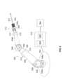
図4を参照すると、第1の例示的な電気手術システム400が示されており、電気手術システム400では、電気手術ネットワーク404が複数の電気手術接続ユニット416(電気手術器具に接続可能)を電気手術器414によって制御される電気手術チャネルに接続する。この例では、手術器具はロボットアーム402A、402B、402Cによってロボット制御されるため、各電気手術接続ユニット416はロボットアーム402A、402B、402Cに接続されて、当該アームに接続された電気手術器具を電気手術チャネルに接続するように構成される。 Referring to FIG. 4, a first
図4のシステム400は3つのロボットアーム402A、402B、402Cを備える。しかし、これら方法及び原理を2つ以上のロボットアームを有する任意のロボット手術システムに適用してもよいことは、当業者にとって明白であろう。各ロボットアーム402A、402B、402Cは、自身の遠位端に、手術器具を当該アームに取り外し可能に取り付けるための取付構造体408を備える。器具410は、その遠位端において、医学的手技に従事するためのエンドエフェクタを備える。ロボットアーム402の例示的な実施は図5に関して以下に記載される。 The
様々なタイプの器具が知られており、そのそれぞれは個々の外科的機能を果たすために適応される。各アーム402は任意のタイプの器具を受け入れ可能であってもよい。例示的なタイプの器具は、電気手術的機能を果たすために適応される電気手術器具410である。上記のように、電気手術では、組織に高周波(すなわち、無線周波数)電流を通すことで所望の効果(例えば、組織の切断又は組織の凝血)を引き起こす。電気手術には、単極及び双極の2種類がある。単極の電気手術では、高周波電流が電気手術器具上のライブ電極又は活性電極から患者上に配置された別の戻り電極(不図示)にかけて患者を通過する。戻り電極は不関電極又は患者電極と呼ぶこともある。双極の電気手術では、活性電極及び戻り電極は電気手術器具内で組み合わせられ、電流が電気手術器具上の活性電極から電気手術器具上の戻り電極にかけて患者を通過する。単極の電気手術用に構成された電気手術器具(例えば、活性電極のみを備える電気手術器具)を本明細書では単極の電気手術器具と呼び、双極の電気手術用に構成された電気手術器具(例えば、活性電極及び戻り電極の両方を備える電気手術器具)を本明細書では双極の電気手術器具と呼ぶ。 Various types of instruments are known, each adapted to perform a particular surgical function. Each arm 402 may be capable of receiving any type of instrument. An exemplary type of instrument is an
電気手術器具は駆動電流(駆動電気手術信号と呼ぶこともある)を電気手術器414から受信する。電気手術器414は電気手術器、電気手術エンドユニット、電気手術エンドユニット、又はESUと呼ぶこともある。電気手術器は、典型的には、異なる外科的効果を達成するために複数の異なる電流波形を生成するように構成できる。例えば、多くの標準的な電気手術器はCOAG、CUT、及びBLEND波形を生成するように構成できる。COAG波形は無線周波のバーストからなる。この無線周波は、低電力設定で使用されると乾燥効果を引き起こし、高電力設定で使用されると高周波治療効果を引き起こす。CUT波形はCOAGに比べより低い電圧だがより高い電流の連続波形であり、この連続波形は組織の切断を引き起こす。BLEND波形はCUT波形とCOAG波形との間の波形であるがこれらの組み合わせではない。BLEND波形は、本質的には、CUT波形よりも低いデューティ周期を有するCUT波形である。BLEND波形は、典型的には、15%と75%との間のデューティ周期を有する。offタイムにより、組織が冷却されて止血を多少行うことができる。よって、BLEND波形は、組織が切断されていて止血が必要な場合に使用される。これらが単に例であることと、異なる電気手術器が異なる且つ/又は追加的な波形を生成するように構成されてもよいこととは、当業者にとって明白であろう。 The electrosurgical instrument receives a drive current (sometimes referred to as a drive electrosurgical signal) from
電気手術器414は生成すべき波形(複数可)を設定するための任意の好適な手段を備えてもよい。例えば、電気手術器414は、生成すべき波形(複数可)を設定するための、スイッチ、ボタン、ダイアル等の、機械的手段を備えてもよい。或いは又は加えて、電気手術器414は、例えば、電気手術器414に送信される制御信号を介して電子的に構成されてもよい。例えば、電気手術器は、ロボットアーム402A、402B、402C(以下により詳しく記載)を制御するために使用されるロボット制御システムに接続されてもよく、ロボット制御システムのコマンドインターフェースから、外科医又はその他のユーザが、生成すべき波形(複数可)を設定可能であってもよい。ロボット制御システムは、当該波形(複数可)の設定を電気手術器414に送信してもよい。これにより、電気手術器414は、当該設定された波形(複数可)を有する電流を生成できるように自身を構成する。
典型的には、設定された波形を有する電流(本明細書では、駆動電気手術信号と呼ぶこともある)を電気手術器に接続された電気手術器具の活性電極に適用するための手段もある。場合によっては、電気手術器414は、起動信号の受信に呼応して駆動電気手術信号を出力するように構成されてもよい。この場合、電気手術器414は手動トリガー機構を備えてもよく又は手動トリガー機構に接続されてもよい。手動トリガー機構は、これに限られないが、例えばペダル又はボタンなどである。このペダル又はボタンは、ユーザによって作動されたときに電気手術器414に駆動電気手術信号(例えば、設定された波形を有する電流)を出力させる。他の場合としては、電気手術器414はロボット制御システムに接続されてもよく、ロボット制御システムのコマンドインターフェースから、外科医又はその他のユーザが、電気手術器414が駆動電気手術信号を出力するように指示可能であってもよい。この指示は起動信号として電気手術器414に直接的に送信されてもよい。この起動信号により、電気手術器414が駆動電気手術信号(すなわち、選択された/設定された波形を有する電流)を出力する。或いは、この指示は制御信号として下記の電気手術接続ユニットに送信されてもよく、この制御信号により、電気手術接続ユニットが起動信号を電気手術器に送信する。 There is also typically means for applying a current having a set waveform (sometimes referred to herein as a drive electrosurgical signal) to the active electrode of an electrosurgical instrument connected to the electrosurgical instrument. . In some cases,
一方、他の場合としては、電気手術器414は電源がオンになるとすぐに駆動電気手術信号を出力するように構成されてもよく、電気手術器414及び電気手術器具の活性電極はユーザからの入力に呼応して制御可能に接続されてもよい。例えば、電気手術器具が(ロボット制御とは反対に)手動で制御される場合、電気手術器具はボタン等の手動トリガー機構を有してもよい。手動トリガー機構は、ユーザによって作動されたときに、電気手術器によって出力された駆動電気手術信号を電気手術器具の活性電極に送る。図4の例のように電気手術器具がロボット制御される場合、電気手術接続ユニット416は、ユーザから受信したトリガー入力に呼応して生成された制御信号に反応して、電気手術器によって出力された駆動電気手術信号を電気手術器具の活性電極に動的に送るように構成されてもよい。このことは以下により詳しく記載する。 Alternatively, however, the
各ロボットアーム402A、402B、402Cは電気手術接続ユニット416も備える。電気手術接続ユニット416は、ロボットアーム402A、402B、402Cに取り付けられた電気手術器具と電気手術ネットワーク404との間の電気手術インターフェースとして機能するように構成される。具体的には、電気手術接続ユニット416は、電気手術ネットワーク404から駆動電気手術信号を受信してこの受信された駆動電気手術信号をロボットアーム402A、402B、402Cに取り付けられた電気手術器具に出力するように構成される。場合によっては、電気手術接続ユニット416は、ロボットアーム402A、402B、又は402Cに取り付けられた電気手術器具から又は電気手術接続ユニットに接続された患者電極から戻り電気手術信号を受信しこの受信された戻り電気手術信号を電気手術ネットワーク404に出力するように、構成されてもよい。 Each
例によっては、電気手術接続ユニット416は、電気手術ネットワーク404に接続可能な入力ポート418と、アームに取り付けた電気手術器具に接続可能な出力ポート422と、を備えてもよい。電気手術接続ユニット416は入力ポート418にて駆動電気手術信号を受信し出力ポート422にて駆動電気手術信号を出力するように構成される。場合によっては、入力ポート418は、電気手術ネットワーク404に(直接的又は間接的に)接続された又は電気手術ネットワーク404の一部をなす1本以上の電気手術ケーブル420を受け入れるように構成されてもよい。他の場合としては、入力ポートは、電気手術ネットワーク404に接続できるケーブルと一体であってもよい。同様に、出力ポート422は、電気手術器具に(直接的又は間接的に)接続された1本以上の電気手術ケーブルを受け入れるように構成されてもよい。他の場合としては、出力ポートは、電気手術器具に(直接的又は間接的に)接続できるケーブルと一体であってもよい。 In some examples, the
場合によっては、入力ポート418及び出力ポート422は、入力ポート418を介して受信された任意の駆動電気手術信号が自動的に出力ポート422にて出力され且つ同様に出力ポート422を介して受信された任意の戻り電気手術信号が自動的に入力ポート418にて出力されるように、(例えば、ワイヤ若しくは導体、又はワイヤ組若しくは導体組を介して)恒久的に接続されてもよい。他の場合としては、電気手術接続ユニット416は、入力ポート418と出力ポート422との間に位置するスイッチングユニット426をさらに備えてもよい。スイッチングユニット426は、電気手術制御ユニット406から受信された制御信号に反応して入力ポート418を出力ポート422に制御可能に接続するように構成される。場合によっては、スイッチングユニット426は、入力ポート418と出力ポート422とに連続している1つ以上のスイッチを備える。この場合、入力ポート418は、スイッチングユニット426のスイッチを閉じることで出力ポート422と動的に接続される。スイッチは、電気機械的リレー(EMR)又は定常リレー(SSR)等のリレーによって実現されてもよい。 In some cases,
電気手術接続ユニット416は、任意の好適な通信手段を介して電気手術制御ユニット406から制御信号を受信してもよい。例えば、電気手術制御ユニット406は電気手術接続ユニット416と無線通信リンクを確立させて制御信号を無線通信リンクを介して送信可能であってもよい。他の例においては、電気手術制御ユニット406は有線通信リンクを介して電気手術接続ユニット416に接続されてもよい。
電気手術ネットワーク404は、本明細書では電気手術ネットワーク、ES-ネットワーク、又はESNと呼ぶこともある。電気手術ネットワーク404は、複数の電気手術接続ユニットを電気手術器によって制御される電気手術チャネルに接続する複数の電気手術リンクを備える。電気手術チャネルは1組のワイヤである。1組のワイヤは、1組の信号を伝達するために使われる。この1組の信号は、電気手術器具へ又は電気手術器具から伝達されることで、電気手術器具の動作を制御する。電気手術チャネルが伝達する信号の数は電気手術チャネルのタイプに基づく。例えば、双極の電気手術チャネルは少なくとも駆動電気手術信号と戻り電気手術信号とを伝達する。これに対し、単極の電気手術チャネルは少なくとも駆動電気手術信号を伝達する。
電気手術チャネルは電気手術器414によって制御される。具体的には、電気手術器414は電気手術チャネルの駆動電気手術信号を生成する。電気手術ネットワーク404は、電気手術チャネルを制御する電気手術器414に直接的に接続されてもよく、又は、電気手術チャネルを制御する電気手術器414に間接的に接続されてもよい。図4の例では、電気手術ネットワーク404は電気手術器414に直接的に接続されるが、他の例においては、電気手術ネットワーク404は、電気手術分配ユニット又は電気手術マルチプレクサ(以下により詳しく記載)などの別の電気手術出力装置(駆動電気手術信号を出力できる装置)に接続されてもよい。 The electrosurgical channel is controlled by
電気手術リンクは、電気手術チャネルの電気手術信号を伝達する1組の1本以上の電気手術ワイヤ(電気手術母線、電気手術レール、又は電気手術導体と呼ばれることもある)である。各電気手術リンクを形成するワイヤの数は、電気手術ネットワーク404によってサポートされている電気手術チャネルのタイプに依存する。例えば、電気手術ネットワーク404が双極の電気手術チャネルをサポートするようデザインされる場合、各電気手術リンクは少なくとも2本のワイヤ、即ち、駆動電気手術信号をこの信号により制御される電気手術器具に伝達する一方のワイヤと、戻り電極により取り込まれた戻り電気手術信号を伝達する第2ワイヤと、を備える。よって、この例では、生成された信号と戻り信号の両方が電気手術ネットワーク404を通じて伝達される。 An electrosurgical link is a set of one or more electrosurgical wires (sometimes called electrosurgical busbars, electrosurgical rails, or electrosurgical conductors) that carry electrosurgical signals in an electrosurgical channel. The number of wires forming each electrosurgical link depends on the type of electrosurgical channels supported by
いくつかの電気手術器は、双極の起動信号の受信に呼応して双極の電気手術器具用の駆動電気手術信号を生成するように構成される。場合によっては、双極の起動信号は電気手術接続ユニットによって生成されてもよい。この場合、電気手術リンクは、電気手術ネットワーク404を介して双極の起動信号を伝達する、追加的なワイヤを備えてもよい。他の場合としては、双極の起動信号は他の装置によって生成されてもよい。この場合、電気手術リンクは、電気手術ネットワーク404を介して双極の起動信号を伝達する、ワイヤを備えなくてもよい。 Some electrosurgical instruments are configured to generate a driving electrosurgical signal for a bipolar electrosurgical instrument in response to receiving a bipolar activation signal. In some cases, the bipolar activation signal may be generated by the electrosurgical connection unit. In this case, the electrosurgical link may comprise additional wires that carry the bipolar activation signal over the
別の例においては、電気手術ネットワーク404が単極の電気手術チャネルをサポートするように構成される場合、各電気手術リンクは、電気手術器414によって生成された電気手術信号を電気手術器具に伝達する少なくとも1本のワイヤを備えてもよい。場合によっては、患者電極は別の接続部を介して電気手術器414に接続されてもよく、戻り電気手術信号はこの別の接続部を介して電気手術器に送られる。この場合、電気手術リンクは、電気手術ネットワークを介して戻り電気手術信号を伝達する、追加的なワイヤを備えなくてもよい。他の場合としては、患者電極は電気手術接続ユニットに接続されてもよく、患者電極によって取り込まれた戻り電気手術信号は電気手術ネットワーク404によって電気手術器に送信されてもよい。この場合、電気手術リンクは、電気手術ネットワークを介して戻り電気手術信号を伝達する、追加的なワイヤを備えてもよい。 In another example, if
単極の電気手術器具用のCUT及びCOAG駆動電気手術信号の両方を生成可能ないくつかの電気手術器は、CUT起動信号の受信に呼応してCUT駆動電気手術信号を生成及び出力し且つCOAG駆動電気手術信号の受信に呼応してCOAG駆動電気手術信号を出力するように、構成される。場合によっては、電気手術接続ユニットはCUT及びCOAG起動信号を生成するように構成されてもよい。この場合、電気手術リンクは、電気手術ネットワーク404を介してCUT及びCOAG起動信号を伝達する、2本の追加的なワイヤを備えてもよい。一方、他の場合としては、CUT及びCOAG起動信号は他の装置によって生成されてもよい。この場合、電気手術リンクは、電気手術ネットワークを介してCUT及びCOAG起動信号を伝達するための、ワイヤを備えなくてもよい。これにより、電気手術リンクのケーブルをより小さく且つより軽くできる。 Some electrosurgical instruments capable of generating both CUT- and COAG-driven electrosurgical signals for monopolar electrosurgical instruments generate and output CUT-driven electrosurgical signals and COAG-driven electrosurgical signals in response to receiving a CUT activation signal. It is configured to output a COAG drive electrosurgical signal in response to receiving the drive electrosurgical signal. In some cases, the electrosurgical connection unit may be configured to generate CUT and COAG activation signals. In this case, the electrosurgical link may comprise two additional wires that carry the CUT and COAG activation signals over
例によっては、電気手術ネットワーク404は、アーム402A、402B、402Cの電気手術接続ユニット416がスター型構成で接続されるように構成されてもよい。スター型構成において、各電気手術接続ユニット416は電気手術器414によって生成された駆動電気手術信号を別の又は専用の電気手術リンクを介して受信する。各専用リンクは、関連づけられた電気手術接続ユニット416を電気手術器414に直接的に接続してもよいし、又は、関連づけられた電気手術接続ユニット416を中継ユニットに接続してもよい。中継ユニットは、電気手術器又は他の装置から駆動電気手術信号を受信してこの信号を当該リンクを介して電気手術接続ユニットに再配分する。電気手術ネットワーク404用の例示的なスター型構成については図6~図8を参照して以下に記載される。 In some examples,
他の例においては、電気手術ネットワーク404は、アーム402A、402B、402Cの電気手術接続ユニット416がデイジーチェーン構成で接続されるように構成されてもよい。デイジーチェーン構成においては、複数のアーム402A、402B、402Cの電気手術接続ユニット416は直列シーケンスで互いに接続される。例えば、第1アーム402Aの電気手術接続ユニット416は、電気手術リンクを介して第2アーム402Bの電気手術接続ユニット416に接続されてもよく、さらに、第2アーム402Bの電気手術接続ユニット416は別の電気手術リンクを介して第3アーム402Cの電気手術接続ユニット416に接続されてもよい。電気手術器414によって生成された駆動電気手術信号は、電気手術接続ユニット416のうちいずれかに送られてチェーンを介してその他の電気手術接続ユニット416に再配分できる。 In other examples,
電気手術接続ユニット416がデイジーチェーン接続されるように電気手術ネットワーク404が構成される場合、電気手術接続ユニット416のうち1つ以上は、受信された駆動電気手術信号をチェーン内の別の電気手術接続ユニット416に送ることができるように1つ以上の追加的な出力ポートを備えてもよい。場合によっては、入力ポートは、入力ポートにて受信された任意の駆動電気手術信号が追加的な出力ポートで自動的に出力されるように追加的な出力ポートに恒久的に接続又は配線接続されてもよい。他の場合としては、電気手術接続ユニット416は、入力ポートと追加的な出力ポートとの間に位置する1つ以上のスイッチングユニットを備えてもよく、スイッチングユニットは制御信号に基づいて入力ポートと追加的な出力ポートとを制御可能に接続するように構成される。このことは以下により詳しく記載する。電気手術ネットワーク404用の例示的なデイジーチェーン構成について、図9~図11を参照して以下に記載する。 When
これらが単に電気手術ネットワーク404用の例示的な構成であることと、電気手術ネットワーク404が電気手術接続ユニット416を電気手術器414に任意の好適な手法で接続してもよいことと、は当業者にとって明白であろう。例えば、電気手術ネットワーク404は、代替的に、スター型構成とデイジーチェーン構成との組み合わせを利用して電気手術接続ユニット416を電気手術器414に接続してもよい。具体的には、電気手術接続ユニット416のうち2つ以上は、これら電気手術接続ユニット416のうち少なくとも1つが別の電気手術接続ユニット416を介して電気手術器414に接続されるように、互いにデイジーチェーン接続されてもよく、1つ以上の他の電気手術接続ユニット416はスター型構成によって電気手術器に接続されてもよい。 It is not intended that these are merely exemplary configurations for
電気手術制御ユニット406は電気手術出力装置(例えば、電気手術器414)及び/又は電気手術接続ユニット416に接続される装置である。電気手術制御ユニット406は、この接続により、電気手術出力装置(例えば、電気手術器414)及び/又は電気手術接続ユニット416の動作を制御することで、電気手術出力装置(例えば、電気手術器414)と選択された組み合わせの電気手術接続ユニット416の出力ポート422との間に電気手術接続を確立させる。電気手術接続ユニット416の組み合わせは多数の基準に基づいて選択されてもよい。基準としては、どのロボットアーム402A、402B、402Cに電気手術器具410が取り付けられているか、及び、どの電気手術器具が制御又は通電されるべきか、等があるがこれらに限定されない。
場合によっては、電気手術制御ユニット406は、電気手術ネットワーク404のリンクを選択的に有効及び無効にすることで、電気手術器414によって生成された駆動電気手術信号を選択された電気手術接続ユニット416のみが受信するように構成されてもよい。電気手術接続ユニット416同士がスター型構成で接続された場合、電気手術制御ユニット406は電気手術配分装置に制御信号を送信するように構成されてもよい。電気手術配分装置に電気手術接続ユニット416が接続されることで、電気手術配分装置は電気手術器414で受信/生成された駆動電気手術信号を選択された組のリンクのみを介して出力する。この場合、電気手術接続ユニット416は、自身に取り付けられた電気手術器具の動作を駆動電気手術信号が制御すべきである場合にのみ、その駆動電気手術信号を受信してもよい。一方、電気手術接続ユニット416同士がデイジーチェーン構成で接続された場合、電気手術制御ユニット406は電気手術接続ユニット416に制御信号を送信するように構成されてもよく、これにより、電気手術接続ユニット416がチェーン内の選択されたリンクを有効又は無効にすることで、選択された組の電気手術接続ユニット416にのみ電気手術信号が送られる。 In some cases,
他の場合としては、電気手術接続ユニット416が入力ポート418と出力ポート422との間に位置するスイッチングユニットを備える場合、電気手術制御ユニット406は、電気手術接続ユニット416に制御信号を送信することにより、選択された電気手術接続ユニット416の入力ポート418及び出力ポート422間を接続可能にするように、構成されてもよい。 Alternatively, if
さらに他の場合では、電気手術制御ユニット406は、電気手術ネットワーク404のリンクを選択的に有効及び無効にすることも、選択された電気手術接続ユニット416の入力ポート418及び出力ポート422間の接続を選択的に可能にすることも、両方行うように構成されてもよい。 In still other cases, the
場合によっては、電気手術制御ユニット406は、電気手術接続ユニット416及び/又は電気手術出力装置に制御信号を送信することで、1つだけの電気手術接続ユニット416の出力ポートを同一のライブ電気手術チャネルに任意の時点で接続するように、構成されてもよい。一方、異なる電気手術接続ユニット416の出力ポートを異なる電気手術チャネルに接続可能であってもよい。これにより、異なる電気手術器具が異なる電気手術チャネルによって同時に制御されてもよい。 In some cases,
場合によっては、電気手術制御ユニット406は、各ロボットアーム402A、402B、及び402Cに取り付けられた電気手術器具のタイプを示す情報を受信してもよく、電気手術制御ユニット406はこの情報を用いて、任意の電気手術器具が当該タイプの電気手術器具に対応している電気手術チャネルによってのみ制御されることを確実にするように構成されてもよい。例えば、ロボットアーム402A、402B、402Bは、ロボットアーム402A、402B、402Cに取り付けられた手術器具からの情報であって手術器具のタイプを示す情報を受信できるRFIDリーダー等を備えてもよい。電気手術器具が当該タイプの電気手術器具に対応している電気手術チャネルによってのみ制御される(又は当該電気手術チャネルにのみ接続される)ことを電気手術制御ユニット406が確実にする場合、この情報は電気手術制御ユニット406に伝達されてもよい。 In some cases,
電気手術制御ユニット406は1つ以上のプロセッサ428と、メモリ430と、を備えてもよい。メモリ430はコンピュータにより実行可能な指示を記憶するように構成される。この指示は、1つ以上のプロセッサによって実行されたときに、1つ以上のプロセッサに上記の機能を実行させる。場合によっては、電気手術制御ユニット406はコマンドインターフェース(後述)に取り付けられることで、電気手術制御ユニット406の動作が外科医又はその他のユーザからの入力に基づいて制御可能であってもよい。
図5を参照すると、図4のロボットアーム402A、402B、及び/又は402Cのいずれかを実現するために用いても良い例示的なロボットアーム502が示されている。ロボットアーム502は基台504に取り付けられた近位端から延在する。当該アームは多数の剛性のリンク506を備える。リンク同士は回転関節508によって連結される。最近位リンク506aが関節508aによって基台に連結される。最近位リンク506aとその他のリンクとは、関節508のうちさらに遠位の関節によって連続して連結される。好適には、手首部510が4つの個別の回転関節からなる。手首部510は、アームの1つのリンク(506b)をアームの最遠位リンク(506c)に連結する。最遠位リンク506cはアームの遠位端にあり、手術器具512用の取付構造体408を持ち運ぶ。アームの各関節508は、操作されることで当該関節において回転運動させることが可能な1つ以上のモーター514と、当該関節における現在の配置及び/又は負荷に関する情報を提供する1つ以上の位置及び/又はトルクセンサ516と、を有する。これらモーターは、自身が動作駆動する関節よりも近位に配置されることで重量配分を向上してもよい。明確性のため、モーター及びセンサのうちいくつかのみが図5に図示される。アームについては、概ね我々の同時係属中の特許出願PCT/GB2014/053523に記載される通りであってもよい。 Referring to FIG. 5, an exemplary
アームは器具512との接合用の取付構造体408において終端する。器具512は図2に関して記載された形状を有してもよい。取付物408は、器具の繋ぎ目部を駆動するための駆動アセンブリを備える。ロボットアームから器具に駆動伝達するために、駆動アセンブリ接合部の可動接合部要素は器具接合部の対応する可動接合部要素と機械的に係合する。典型的な手術の間は、一の器具は別の器具と数回交換される。従って、器具は手術中にロボットアームに対して着脱可能である。駆動アセンブリ接合部の機能と器具接合部の機能とは、互いに係合するときに駆動アセンブリ接合部と器具接合部との整列を補助する。これにより、ユーザによるこれらの整列に求められる精度は低減する。 The arms terminate in mounting
器具512は手術を行うためのエンドエフェクタを備える。エンドエフェクタは任意の好適な形状を有してもよい。例えば、エンドエフェクタは平坦な顎部、鋸歯状の顎部、グリッパー、鋏、縫合用の針、カメラ、レーザ、メス、ステープラー、焼灼器、吸引器であってもよい。図2に関して記載したように、器具は器具軸とエンドエフェクタとの間に繋ぎ目部を備える。繋ぎ目部は、エンドエフェクタを器具の軸に対して移動可能にする数個の関節を備える。繋ぎ目部における関節はケーブルなどの駆動要素により作動する。これら駆動要素は、器具軸の他方の端部において器具接合部の接合部要素に固定される。従って、ロボットアームは以下のように駆動をエンドエフェクタに伝達する:駆動アセンブリ接合部要素が動くと器具接合部要素が動き、器具接合部要素が駆動要素を動かし、駆動要素が繋ぎ目部の関節を動かし、繋ぎ目部の関節がエンドエフェクタを動かす。
モーター用の制御器、トルクセンサ、及びエンコーダがロボットアームに対して分散配置されている。制御器は通信母線を介してロボット制御ユニット518に接続される。ロボット制御ユニット518はプロセッサ520とメモリ522とを備える。メモリ522は非一時的にソフトウェアを記憶する。ソフトウェアはプロセッサ520により実行でき、これにより、モーター514の動作を制御してアーム502を本明細書に記載されたように動作させる。具体的には、ソフトウェアにより、プロセッサ520を制御でき、これによりモーターを(例えば分散配置された制御器を介して)センサ516と外科医コマンドインターフェース524とからの入力に応じて駆動させる。ロボット制御ユニット518は、ソフトウェアの実行によって生成された出力に応じてモーター514を駆動するためにモーター514に接続される。ロボット制御ユニット518は、センサ516からの感知された入力を受信するためにこれらのセンサに接続され、コマンドインターフェース524からの入力を受信するためにこのコマンドインターフェースに接続される。それぞれの接続は、例えば、電気ケーブル又は光ケーブルによるものでもよいし、無線接続によるものでもよい。コマンドインターフェース524は1つ以上の入力装置を備えるので、ユーザがエンドエフェクタの動作を所望の手法で要求できる。これら入力装置は、例えば、制御ハンドル又はジョイスティックなどの手動で操作可能な機械的入力装置、又は光学的ジェスチャーセンサなどの非接触型入力装置であり得る。メモリ522に記憶されたソフトウェアは、これらの入力に応答し、それに応じてアーム及び器具の関節を所定の制御方式に従って動かすように構成される。制御方式は、コマンド入力に呼応してアーム及び器具の動作をやわらげる安全機能を含んでもよい。従って、まとめると、コマンドインターフェース524における外科医は、器具512を制御して所望の外科手技を行うように動かすことができる。ロボット制御ユニット518及び/又はコマンドインターフェース524はアーム502から遠く離れていてもよい。 Controllers for the motors, torque sensors, and encoders are distributed with respect to the robot arm. The controller is connected to the
複数のアームがある場合、各アームは同一のロボット制御ユニット518又は異なるロボット制御ユニット518によって制御されてもよい。 If there are multiple arms, each arm may be controlled by the same
図6~図8を参照すると、電気手術ネットワーク404用の例示的なスター型構成が示されている。 6-8, an exemplary star configuration for
図6は、電気手術ネットワーク404が第1の例示的なスター型構成を有する電気手術システム600を示す。この例では、電気手術ネットワーク404は複数のリンク602、604、及び606を備え、各電気手術接続ユニット416はリンク602、604、606のうち1つを介して電気手術器414に直接的に接続される。具体的には、第1ロボットアーム402Aの電気手術接続ユニット416は第1リンク602を介して電気手術器414に接続され、第2アーム402Bの電気手術接続ユニット416は第2リンク604を介して電気手術器414に接続され、第3アーム402Cの電気手術接続ユニット416は第3リンク606を介して電気手術器414に接続される。 FIG. 6 shows an
場合によっては、電気手術器414は、生成された駆動電気手術信号をどのリンク602、604、606が受信するかを制御可能でなくてもよい。その結果、電気手術器によって生成された任意の駆動電気手術信号は、電気手術器414に接続された全てのリンク602、604、606を介して自動的に送信されてもよい。言い換えると、全てのリンク602、604、606はライブ状態又は作動状態状態である。これは、この場合、電気手術器414に接続された全ての電気手術接続ユニット416が電気手術器414によって生成された任意の駆動電気手術信号を受信する、ということを意味する。よって、電気手術器414によって生成された駆動電気手術信号が電気手術ネットワーク404を介して送信される当該駆動電気手術信号によって制御されるべき電気手術器具410に取り付けられた出力ポート422からのみ出力されるのを確実にするために、電気手術接続ユニット416は、入力ポート418を出力ポート422に制御可能に接続するスイッチングユニット426を備える。電気手術制御ユニット406は選択された電気手術接続ユニット416に制御信号を送信するように構成される。この制御信号は、対応する入力ポート418及び出力ポート422間の接続をそれら電気手術接続ユニット416のスイッチングユニット416によって確立させる。 In some cases,
他の場合としては、電気手術器414は、制御信号(制御ユニットによって生成されてもよい)に呼応して、この生成された電気手術信号を任意の選択された組み合わせのリンク602、604、606を介して制御可能に送信可能であってもよい。例えば、電気手術器414は、制御信号に反応してリンクのうち1つだけを介して又はリンクのうち2つを介して又は3つのリンク全てを介して駆動電気手術信号を送信可能であってもよい。これにより、駆動電気手術信号を、当該駆動電気手術信号によって制御されるべき電気手術器具に接続された電気手術接続ユニット416にのみ送ることができる。よって、この場合、電気手術制御ユニット406は確実に以下を可能にするように構成されてもよい。制御信号を電気手術器414に送信することで、選択された組のリンク(リンクの全て又は一部のみでもよい)を介してのみ電気手術器414が駆動電気手術信号を送信することにより、電気手術器414によって生成された駆動電気手術信号は、当該駆動電気手術信号によって制御されるべき電気手術器具410に取り付けられた出力ポート422からのみ出力される。 Alternatively, the
電気手術器414が制御信号を受信可能で且つ電気手術接続ユニット416がスイッチングユニット426を備える場合、電気手術制御ユニット406は制御信号を電気手術器414と電気手術接続ユニット416とに送信するように構成されてもよい。 If
図7は、電気手術ネットワーク404が第2の例示的なスター型構成を有する電気手術システム700を示す。この例では、電気手術ネットワーク404は複数のリンク704、706、708を備え、電気手術器414は電気手術分配ユニット710に接続され、各電気手術接続ユニット416はリンク704、706、又は708のうち1つを介して電気手術分配ユニット710に直接的に接続される。具体的には、第1アーム402Aの電気手術接続ユニット416はリンク704を介して電気手術分配ユニット710に接続され、第2アーム402Bの電気手術接続ユニット416はリンク706を介して電気手術分配ユニット710に接続され、第3アーム402Cの電気手術接続ユニット416はリンク708を介して電気手術分配ユニット710に接続される。 FIG. 7 shows an
電気手術分配ユニット710は、電気手術出力装置から駆動電気手術信号を受信して、この受信された駆動電気手術信号を1つ以上の電気手術入力装置(駆動電気手術信号を受信可能な装置)に出力することができる任意の装置である。電気手術分配ユニット710は、電気手術信号を電気手術出力装置から受信するための入力ポート(この例では、入力ポートは電気手術器414に接続されている)と、この受信された電気手術信号を電気手術入力装置に出力するための1つ以上の出力ポート(この例では、出力ポートはリンク704、706、708を介して電気手術接続ユニット416の入力ポート418に接続されている)と、を備えてもよい。電気手術分配ユニット710は、入力ポートにて受信された電気手術信号を出力ポートに配分するように構成される。入力ポートは、入力ポートにて受信された任意の駆動電気手術信号が全ての出力ポートに自動的に出力されるように、出力ポートに恒久的に接続又は配線接続されてもよい。或いは、入力ポート及び出力ポートは制御可能に接続されてもよい。例えば、電気手術分配ユニット710は、制御信号に基づいて入力ポートを1つ以上の出力ポートに制御可能に接続可能であってもよい。
図6の例と同様、電気手術分配ユニット710が入力部を1つ以上の出力部に制御可能に接続することが可能である場合、電気手術制御ユニット406は電気手術分配ユニットに制御信号を送信するように構成されてもよく、これにより、リンク704、706、708のうち1つ以上が作動状態になり且つ/又はリンク704、706、708のうちいずれも非作動状態ではなくなり、若しくはリンク704、706、708のうち1つ若しくは2つ以上が非作動状態になるように、電気手術分配ユニット710は受信された駆動電気手術信号を1つ以上の選択されたリンクに配分する。電気手術接続ユニット416がスイッチングユニット426を備える場合、電気手術制御ユニット406は、加えて又は代替的に、制御信号を電気手術接続ユニット416に送信することで、選択された電気手術接続ユニット416に対して入力ポート418及び出力ポート422間の接続を確立させるように構成されてもよい。 Similar to the example of FIG. 6, if
電気手術器414が単一の出力ポートのみを備え且つ/又は電気手術器414がどの出力ポートが駆動電気手術信号を受信するかを制御できない場合に、図6のスター型構成に対して図7のスター型構成は利点があると思われる。後者の場合、図7のスター型構成は、任意のリンクを無効にすることで、電気手術ネットワーク404によって伝達される電気手術チャネルによって制御されるべき電気手術器具に接続されていない電気手術接続ユニット416がその電気手術チャネル用の駆動電気手術信号を受信しないようにしてもよい。 7 versus the star configuration of FIG. The star-shaped configuration of In the latter case, the star configuration of FIG. 7 disables any links so that electrosurgical connection units that are not connected to electrosurgical instruments to be controlled by the electrosurgical channels conveyed by
図8は、電気手術ネットワーク404が第3の例示的なスター型構成を有する電気手術システム800を示す。この例では、電気手術ネットワーク404は複数のリンク802、804、806、及び808を備え、電気手術器414はロボットアーム402A、402B、及び402Cのうち1つ(この例では第1ロボットアーム402A)の電気手術接続ユニット416に第1リンク802を介して接続され、その電気手術接続ユニット416は第2リンク804を介して電気手術分配ユニット810にも接続され、残りの電気手術接続ユニット416は残りのリンク806、808を介して電気手術分配ユニット810に直接的に接続される。具体的には、第2アーム402Bの電気手術接続ユニット416は第3リンク806を介して電気手術分配ユニット810に直接的に接続され、第3アーム402Cの電気手術接続ユニット416は第4リンク808を介して電気手術分配ユニット810に直接的に接続される。図8には、電気手術器414が第1ロボットアーム402Aの電気手術接続ユニット416に直接的に接続されている様子が示されている。しかし、これが単なる例であることと、電気手術器414が任意のロボットアーム402A、402B、402Cの電気手術接続ユニット416に直接的に接続されてもよいこととは、当業者にとって明白であろう。図7に関する上記の電気手術分配ユニット710の記載は図8の電気手術分配ユニット810に同様に適用される。 FIG. 8 shows an
この例では、電気手術器414に直接的に接続されているロボットアーム402Aの電気手術接続ユニット416は、電気手術分配ユニット810に接続可能な第2出力ポート812を備えてもよい。場合によっては、第2出力ポート812は電気手術分配ユニット810に接続される1本以上のケーブルを受け入れるように構成されてもよい。当該電気手術接続ユニット416は、入力ポート418にて受信された駆動電気手術信号(例えば、電気手術器414から受信された電気手術信号)を第2出力ポート812にて出力するように構成される。場合によっては、入力ポート418にて受信された任意の駆動電気手術信号が第2出力ポート812にて自動的に出力されるように、入力ポート418は第2出力ポート812に恒久的に接続又は配線接続されてもよい。一方、他の場合としては、当該電気手術接続ユニット416は、制御信号に反応して入力ポート418を第2出力ポート812に制御可能に接続するように構成される第2スイッチングユニット814を備えてもよい。図8に示された電気手術ネットワークの構成は、電気手術器414がボットアーム402A、402B、402Cのうち1つの近くに容易に配置できる場合に有利であると思われる。 In this example, the
図7の例と同様、電気手術分配ユニット810が入力部を1つ以上の出力部に制御可能に接続できる場合、電気手術制御ユニット406は制御信号を電気手術分配ユニット810に送信するように構成されてもよく、これにより、リンク806及び808のうちいずれも作動状態ではなくなり、又はリンク806及び808のうち一方又は両方が作動状態になるように、電気手術分配ユニット810が入力部を選択された組の出力部(出力部のうちいずれでもない、又は出力部のうち幾つか又は全て)に接続する。電気手術接続ユニット416がスイッチングユニット426を備える場合、電気手術制御ユニット406は、加えて又は代替的に、制御信号を電気手術接続ユニット416に送信することで、選択された電気手術接続ユニット416に対して入力ポート418及び出力ポート422間の接続を確立させるように、構成されてもよい。同様に、電気手術接続ユニット416が追加的なスイッチングユニット814を備える場合、電気手術制御ユニット406は、制御信号を電気手術接続ユニット416に送信することで入力ポート418及び第2出力ポート812間の接続を確立させたり無効にしたりするように、構成されてもよい。 Similar to the example of FIG. 7,
図9~図11を参照すると、電気手術ネットワーク404が例示的なデイジーチェーン構成を有する電気手術システム900、1000、1100が示されている。簡潔に上述したように、デイジーチェーン構成においては、電気手術接続ユニット416は互いに直列シーケンスにて接続され、電気手術接続ユニット416のうち1つは電気手術チャネル用の駆動電気手術信号を(電気手術器414自身から又は電気手術分配ユニットなどの中間装置を介して)受信して当該駆動電気手術信号をチェーンを介してその他の電気手術接続ユニット416に配分する。これらデイジーチェーンの例では、電気手術接続ユニット416のうち1つ以上は、受信された駆動電気手術信号をチェーン内の別の電気手術接続ユニット416に送る1つ以上の追加的な出力ポート912、1012を備えてもよい。このような電気手術接続ユニット416では、入力ポート418にて受信された任意の駆動電気手術信号が追加的な出力ポート912、1012に自動的に送り出されるように、入力ポート418は追加的な出力ポート912、1012に恒久的に接続又は配線接続されてもよい。或いは、電気手術接続ユニット416は1つ以上の追加的なスイッチングユニット914、1014を備えてもよい。追加的なスイッチングユニット914、1014は、入力ポート418と追加的な出力ポート912、1012との間に位置し、制御信号に反応して入力ポート418を追加的な出力ポート912、1012に制御可能に接続するように構成される。 9-11,
図9は、電気手術ネットワーク404が第1の例示的なデイジーチェーン構成を有する電気手術システム900を示す。この例では、電気手術ネットワークは複数のリンク902、904、906を備え、電気手術接続ユニット416同士はリンク902、904を介してデイジーチェーン接続され、電気手術器414はリンク906を介してデイジーチェーンに接続される。具体的には、第1アーム402Aの電気手術接続ユニット416がリンク902を介して第2アーム402Bの電気手術接続ユニット416に接続され、第2アーム402Bの電気手術接続ユニット416がリンク904を介して第3アーム402Cの電気手術接続ユニット416に接続されて、電気手術接続ユニット416同士のデイジーチェーンが形成される。一旦電気手術接続ユニット416同士がデイジーチェーン接続されると、駆動電気手術信号をチェーン内の任意の電気手術接続ユニット416に送ることができ、この駆動電気手術信号をチェーンを介してその他の電気手術接続ユニット416に配分できる。 FIG. 9 shows an
図9の例では、電気手術器414はリンク906を介して第1アーム402Aの電気手術接続ユニット416に直接的に接続される。よって、この例では、第1及び第2アーム402A、402Bの電気手術接続ユニット416はそれぞれ、入力ポート418を介して受信された駆動電気手術信号をチェーンの別の電気手術接続ユニット416に送るために使われる追加的な出力ポート912を備える。具体的には、第1アーム402Aの電気手術接続ユニット416は、第2アーム402Bの電気手術接続ユニット416の入力ポート418に接続される追加的な出力ポート912を備えることで、第1アーム402Aの電気手術接続ユニット416は入力ポート418を介して電気手術器414から受信された駆動電気手術信号を第2アーム402Bの電気手術接続ユニット416に送ることができる。また、第2アーム402Bの電気手術接続ユニット416は、第3アーム402Cの電気手術接続ユニット416の入力ポート418に接続される追加的な出力ポート912を備えることで、第2アーム402Bの電気手術接続ユニット416は入力ポート418を介して第1アーム402Aの電気手術接続ユニット416から受信された駆動電気手術信号を第3アーム402Cの電気手術接続ユニット416に送ることができる。 In the example of FIG. 9,
図9は第1アーム402Aに直接的に接続された電気手術器414を示すが、電気手術器414は任意のアーム402A、402B、又は402Cの電気手術接続ユニット416に直接的又は間接的に接続できる。例えば、図10は、電気手術ネットワーク404が第2の例示的なデイジーチェーン構成を有する電気手術システム1000を示す。この例では、電気手術ネットワーク404はリンク1002、1004、及び1006を備える。図10のデイジーチェーン構成は、電気手術器414が第1アーム402Aの電気手術接続ユニット416に直接的に接続される代わりに第2アーム402Bの電気手術接続ユニット416に直接的に接続されている点を除いて、図9に示されたデイジーチェーン構成と同一である。この例では、第2アーム402Bの電気手術接続ユニット416は、受信された駆動電気手術信号をその他の電気手術接続ユニットに送るために使われる2つの追加的な出力ポート912、1012を備える。 Although FIG. 9 shows
具体的には、第2アーム402Bの電気手術接続ユニット416は、第1アーム402Aの電気手術接続ユニット416の入力ポート418に接続された追加的な出力ポート1012を備えることで、第2アーム402Bの電気手術接続ユニット416は自身の入力ポート418を介して電気手術器414から受信された駆動電気手術信号を第1アーム402Aの電気手術接続ユニット416に送ることができる。第2アーム402Bの電気手術接続ユニット416は、第3アーム402Cの電気手術接続ユニット416の入力ポート418に接続されたさらに追加的な出力ポート912も備えることで、第2アーム402Bの電気手術接続ユニット416は自身の入力ポート418を介して電気手術器414から受信された駆動電気手術信号を第3アーム402Cの電気手術接続ユニット416に送ることができる。 Specifically, the
さらに、図9及び図10は電気手術器414がチェーン内の電気手術接続ユニット416に直接的に接続されている様子が示されているが、他の例においては、電気手術器414がチェーンに間接的に接続されてもよい。例えば、図11は、電気手術ネットワーク404が第3の例示的なデイジーチェーン構成を有する電気手術システム1100を示す。この例では、電気手術ネットワーク404はリンク1102、1104、及び1106を備える。図11に示されたデイジーチェーン構成は、電気手術器414が電気手術分配ユニット1110に直接的に接続され且つ電気手術分配ユニット1110は第1アーム402Aの入力ポート418に接続されている点を除いて、図9に示された例示的なデイジーチェーン構成と同一である。図11は第1アーム402Aの電気手術接続ユニット416に直接的に接続された電気手術分配ユニット1110を示すが、電気手術分配ユニット1110が電気手術接続ユニット416のうちいずれに接続されてもよいことは、当業者にとって明白であろう。図11に示された構成は、どの出力ポートが駆動電気手術信号を受信するかを電気手術器414が制御できない場合に、図9及び図10に示された構成に対する利点を提供すると考えられる。 Further, although FIGS. 9 and 10 show the
図9~図11のデイジーチェーンの例のいずれにおいても、電気手術器414によって出力された電気手術信号がアーム402A、402B、及び/又は402Cのうち所望の組(1つ、幾つか、又は全てのアームを含んでもよい)の出力ポート422からのみ出力されることを確実にするためには、電気手術制御ユニット406は1つ以上の電気手術接続ユニット416に制御信号を送信することで、選択された電気手術接続ユニット416のみに対して入力ポート418及び出力ポート422間の接続を確立させるように、構成されてもよい。例えば、電気手術ネットワークによって伝達される電気手術チャネルによって制御されるべき電気手術器具410に第1アーム402Aのみが接続される場合、電気手術制御ユニット406は1つ以上の制御信号を生成してもよく、この制御信号により、第1アーム402Aの電気手術接続ユニット416のスイッチングユニット426を有効にし(すなわち、入力ポート418及び出力ポート422間の接続を確立させ)、その他のアーム402B及び402Cの電気手術接続ユニット416のスイッチングユニット426を無効とする(すなわち、入力ポート418及び出力ポート422間の接続を確立させない)。 In any of the daisy-chain examples of FIGS. 9-11, the electrosurgical signals output by
電気手術接続ユニット416のうち1つ以上が入力ポート418と追加的な出力ポート912、1014との間に追加的なスイッチングユニット914、1014を備える場合、電気手術制御ユニット406は1つ以上の制御信号を電気手術接続ユニット416に送信するように構成されてもよく、この制御信号により、選択されたアーム402A、402B、及び/又は402Cの追加的なスイッチングユニット914、1014のみが有効になる。これにより、電気手術器414によって生成された駆動電気手術信号を電気手術接続ユニット416が別の電気手術接続ユニット416に送る必要がない限り又は駆動電気手術信号を電気手術接続ユニット416が自身に取り付けられた電気手術器具に送る必要がない限り、その電気手術接続ユニット416は駆動電気手術信号を受信しない。例えば、図9及び図10の構成において、電気手術ネットワーク404により伝達される電気手術チャネルによって制御されるべき電気手術器具410に第2アーム402Bのみが取り付けられる場合、電気手術制御ユニット406は1つ以上の制御信号を電気手術接続ユニット416に送信してもよく、この制御信号により、第1アーム402Aの電気手術接続ユニット416の追加的なスイッチングユニット914が作動状態又は有効になり、第2アーム402Bの追加的なスイッチングユニット914が無効又は非作動状態になる。これにより、電気手術器414によって生成された駆動電気手術信号が第1アーム402Aから第2アーム402Bに送られるが、第2アーム402Bから第3アーム402Cへは駆動電気手術信号を送信させないようにする。 If one or more of the
デイジーチェーンの例によっては、電気手術制御ユニット406は、例えば電気手術接続ユニット416から受信された情報に基づいて電気手術ネットワーク404内における電気手術器414の場所及び/又は電気手術ネットワーク404の構成を動的に検出可能であってもよく、電気手術器の検出された場所及び/又は電気手術ネットワーク404の検出された構成に基づいて任意のリンク及び/又は入力-出力ポート間の接続を動的に有効/無効にしてもよい。例えば、電気手術接続ユニット416は、入力ポート418及び/又は出力ポート422に電気手術ケーブルがいつ挿入されたかを機械的又は電気的に感知してこの情報を電気手術制御ユニット406に送信可能であってもよい。具体的には、電気手術接続ユニットの入力ポート418及び/又は出力ポート422は、当該ポートに電気手術ケーブルがいつ挿入されたかを検出可能な機械的センサ(マイクロスイッチなどだが、これに限定されない)を備えてもよい。或いは、入力ポート418及び/又は出力ポートは、ケーブルが当該ポートに接続されたことを示すインピーダンスの変化又は電圧の変化を検出可能な電気センサ(当該ポートの1つ以上のピンに接続された電気回路などだが、これに限定されない)を備えてもよい。他の例においては、入力ポート及び/又は出力ポート422は信号感知手段を備えてもよい。この場合、電気手術制御ユニット406は、各手術器接続点に依頼を送信することで電気手術器からの入力を依頼し、同時に、出力ポート422が対応する入力ポート418に接続されていなかったことを確認してもよい。その後、各接続点は駆動電気手術信号を「待つ」ことになる。全ての場合において、駆動電気手術信号を受信する入力ポートを有する電気手術接続ユニット416であれば、駆動電気手術信号を検出し、制御信号を介して電気手術制御ユニット406に報知することになる。 In some daisy chain examples, the
上記のシステムは電気手術接続ユニットを単一の電気手術チャネルに接続すると記載されているが、他の例においては、電気手術接続ユニットは複数の電気手術チャネルに接続されてもよい。各チャネルは異なる駆動電気手術信号を伝達してもよい。これにより、電気手術器を再構成することなく、アームに取り付けられた電気手術器具に異なる駆動電気手術信号を容易に送ることを可能であるようにしてもよい。或いは又は加えて、これにより、異なる駆動電気手術信号を異なる電気手術器具に同時に送ることを可能であるようにしてもよい。例えば、これにより、第1アーム(例えば、アーム402A)に取り付けられた電気手術器具が第1駆動電気手術信号により駆動可能であるようにし、第2アーム(例えば、アーム402B)に取り付けられた電気手術器具が第2駆動電気手術信号により同時に駆動可能であるようにしてもよい。全てのチャネルが同一の電気手術器によって制御されてもよく、又は、2つ以上のチャネルが異なる電気手術器によって制御されてもよい。電気手術接続ユニット416が複数の電気手術チャネルに接続される例示的な電気手術システムについては図12~図14を参照して記載する。 Although the above system is described as connecting an electrosurgical connection unit to a single electrosurgical channel, in other examples an electrosurgical connection unit may be connected to multiple electrosurgical channels. Each channel may carry a different drive electrosurgical signal. This may allow different drive electrosurgical signals to be easily sent to the arm-mounted electrosurgical instrument without reconfiguring the electrosurgical instrument. Alternatively or additionally, this may allow different driving electrosurgical signals to be sent to different electrosurgical instruments simultaneously. For example, this allows an electrosurgical instrument attached to a first arm (eg,
図12を参照すると、電気手術接続ユニット416が複数の電気手術チャネルに接続された第1の例示的な電気手術システム1200が示されている。この例では、説明のし易さのため、1つの電気手術接続ユニット416が示される。しかし、上記の構成のうちいずれかに従って複数の電気手術接続ユニット416が電気手術ネットワーク404、1204に接続されてもよいことは、当業者にとって明白であろう。この例では、電気手術接続ユニット416を2つの電気手術チャネルに静的に接続する2つの電気手術ネットワーク404、1204がある。具体的には、第1電気手術ネットワーク404は電気手術接続ユニット416を第1電気手術チャネルに接続し、第2電気手術ネットワーク1204は電気手術接続ユニット416を第2電気手術チャネルに接続する。これら電気手術チャネルは同一のタイプのものであっても異なるタイプのものであってもよい。例えば、2つの単極のチャネル、2つの双極のチャネル、又は1つの単極のチャネル及び1つの双極のチャネルがあってもよい。電気手術ネットワーク404、1204は上記構成のうちいずれ(例えば、スター型、デイジーチェーン)を有してもよい。 Referring to FIG. 12, a first
電気手術接続ユニット416は、電気手術ネットワーク404、1204の両方に接続された入力ポート418と、各電気手術チャネルにつき1つの出力ポート422、1222と、を備える。入力ポート418を介して受け入れられる第1電気手術チャネルは、第1チャネルで受信された駆動電気手術信号が第1出力ポート422にて出力されるように第1出力ポート422に接続される。入力ポート418を介して受け入れられる第2電気手術チャネルは、第2電気手術チャネルを介して受信された駆動電気手術信号が第2出力ポート1222にて出力されるように第2出力ポート1222に接続される。この例では、アームに取り付けられた電気手術器具が出力ポート422又は1222のうち一方に手動で接続できる。図12には示されていないが、電気手術接続ユニット416は入力ポート418と出力ポート422、1222との間に1つ以上のスイッチングユニットを備えてもよい。このスイッチングユニットは、制御信号(制御ユニットによって生成されてもよい)に呼応して、入力ポート418を介して受け入れられる第1及び第2チャネルを出力ポート422、1222に制御可能に接続する。 The
図13を参照すると、電気手術接続ユニット416が複数の電気手術チャネルに接続された第2の例示的な電気手術システム1300が示されている。この例は、以下の点を除き、図12に示された例と同一である。電気手術接続ユニット416が電気手術チャネルごとに1つの出力ポートを備える代わりに、1つの出力ポート422があり、電気手術接続ユニット416はスイッチングユニット1302を備え、スイッチングユニット1302は制御信号(電気手術制御ユニット406によって生成されてもよい)に呼応して第1及び第2チャネルのうち一方を出力ポート422に制御可能に接続する(又は第1及び第2チャネルのうちいずれも出力ポート422に制御可能に接続しない)。これにより、電気手術器具の電気手術接続ユニット416への接続を断ったり再確立したりすることなく、アームに取り付けられた電気手術器具が第1電気手術チャネル又は第2電気手術チャネルに動的に接続可能となる。この例では、第1及び第2電気手術チャネルは、典型的には、同一のタイプのものである(例えば、第1及び第2電気手術チャネルは双極のチャネルである、又は、第1及び第2チャネルは単極のチャネルである)。 Referring to FIG. 13, a second
他の例においては、電気手術接続ユニットは図12及び図13に示された構成の組み合わせをサポートしてもよい。例えば、電気手術接続ユニット416は1つ以上の電気手術ネットワークを介して3つの異なるチャネルを受け入れてもよく、電気手術チャネルのうち2つは第1出力ポートに制御可能に接続された同一のタイプのものであってもよく、第3電気手術チャネルは第2出力ポートに直接的に又は制御可能に接続された異なるタイプのものであってもよい。 In other examples, an electrosurgical connection unit may support a combination of the configurations shown in FIGS. 12 and 13. FIG. For example, the
場合によっては、図12及び図13のように電気手術リンクのワイヤが特定のチャネル専用である代わりに、電気手術ネットワークの電気手術リンクのワイヤは複数のチャネルのうち1つに動的に割り当てられてもよい。例えば、図14を参照すると、電気手術接続ユニット416が複数の電気手術チャネルに接続された第3の例示的な電気手術システム1400が示される。この例では、1つの電気手術ネットワーク404があり、電気手術ネットワーク404の各電気手術リンク1402、1404は、複数のチャネル1422、1424、1426、1428、1430、1432のうち1つに動的に割り当てられる複数の電気手術ワイヤ又は導体1406、1408、1410、1412、1414、1416、1418、1420を備える。具体的には、図14の電気手術システム1400は電気手術マルチプレクサ(MUX)1434を備える。電気手術マルチプレクサ(MUX)1434は、複数の電気手術チャネル1422、1424、1426、1428、1430、1432を受け入れ、制御信号(制御ユニットによって生成及び送信されてもよい)に呼応して電気手術チャネル1422、1424、1426、1428、1430、1432のうち1つ以上を電気手術リンクのワイヤのうち1本以上に制御可能に接続する。このようなシステムにより、複数の電気手術チャネルが異なる電気手術器具に動的に割り当て可能となる。 In some cases, instead of dedicating the wires of the electrosurgical links to specific channels as in FIGS. 12 and 13, the wires of the electrosurgical links of the electrosurgical network are dynamically assigned to one of multiple channels. may For example, referring to FIG. 14, a third
図14の例では、電気手術MUX1434は6つの電気手術チャネル1422、1424、1426、1428、1430、1432を受け入れるように構成され、各リンク1402は4本のワイヤ1406、1408、1410、1412、1414、1416、1418、1420を備える。しかし、電気手術チャネルが6つより多く又は少なく、及び/又は、リンクが有するワイヤが4つより多く又は少ない場合でも本明細書に記載された技術及び原理を利用してもよいことは、当業者にとって明白であろう。 In the example of FIG. 14,
各電気手術チャネルに関連づけられるワイヤの数は当該電気手術チャネルのタイプに基づいてもよい。例えば、単極の電気手術チャネルは、駆動電気手術信号を電気手術スイッチングユニット(ひいては、電気手術スイッチングユニットに取り付けられた電気手術器具)に送信する1本のワイヤに関連づけられてもよく、双極の電気手術チャネルは2本のワイヤに関連づけられてもよい。2本のワイヤとは、駆動電気手術信号を電気手術接続ユニット(ひいては、電気手術接続ユニットに取り付けられた電気手術器具)に送信する第1ワイヤと、戻り電気手術信号を電気手術接続ユニットから電気手術器に送信する第2ワイヤと、である。電気手術チャネルの全てが同一のタイプのものであってもよく、又は、異なるタイプの組み合わせであってもよい。図14の例では、それぞれが1本のワイヤ1436、1438、1440、1442に関連づけられた4つの単極の電気手術チャネル1422、1424、1428、及び1430と、それぞれが2本のワイヤ1444及び1446と1448及び1450とに関連づけられた2つの双極の電気手術チャネル1426、1432と、がある。しかし、これが単なる例であることと、その他のシステムが異なる数の電気手術チャネルを備えてもよいことと、チャネルが異なる数のワイヤに関連づけられてもよいこととは、当業者にとって明白であろう。 The number of wires associated with each electrosurgical channel may be based on the type of electrosurgical channel. For example, a unipolar electrosurgical channel may be associated with a single wire that transmits a driving electrosurgical signal to an electrosurgical switching unit (and thus an electrosurgical instrument attached to the electrosurgical switching unit); An electrosurgical channel may be associated with two wires. The two wires are a first wire that transmits drive electrosurgical signals to the electrosurgical connection unit (and thus the electrosurgical instrument attached to the electrosurgical connection unit), and a return electrosurgical signal that is electrically transmitted from the electrosurgical connection unit. a second wire that transmits to the surgical instrument; All of the electrosurgical channels may be of the same type or may be a combination of different types. In the example of FIG. 14, four monopolar
図14の例では、電気手術チャネル1422、1424、1426、1428、1430、1432は1つの電気手術器414によって制御される(すなわち、1つの電気手術器414は、チャネルに対して、駆動電気手術信号を生成し任意に戻り電気手術信号を受信する)。一方、他の例においては、電気手術チャネルのうち1つ以上が異なる電気手術器によって制御されてもよい。例えば、最初の3つの電気手術チャネル1422、1424、1426が第1電気手術器によって制御されてもよく、後半の3つの電気手術チャネル1428、1430、1432が2つ目の異なる電気手術器によって制御されてもよい。 In the example of FIG. 14, the
上記のように、電気手術MUX1434は電気手術チャネル1422、1424、1426、1428、1430、1432のうち1つ以上を電気手術ネットワークの電気手術リンクのワイヤのうち1本以上に動的にマッピングするように構成される。本明細書において、「電気手術チャネルを電気手術リンクの1本以上のワイヤにマッピングする」というフレーズは、チャネルの1本以上のワイヤが電気手術ネットワークの電気手術リンクの1本以上のワイヤに電気的に接続されることでチャネルを電気手術接続ユニット416に接続すること、を意味するために使われる。例えば、制御信号に反応して、電気手術MUX1434は、第1チャネル1422のワイヤ1436を電気手術リンク1402の第1ワイヤ1406に電気的に接続し、第3チャネル1426のワイヤ1444及び1446を電気手術リンク1402の第3及び第4ワイヤ1410及び1412に電気的に接続してもよい。これにより、電気手術接続ユニット416は第1及び第3チャネル1422及び1426に接続される。 As described above, the
電気手術リンクのワイヤ1406、1408、1410、1412、1414、1416、1418、1420に任意の時点でマッピングできるチャネルの数は、リンクごとのワイヤの数とチャネルごとのワイヤの数とに依存する。例えば、各リンクが4本のワイヤを備えており、単極のチャネルが1本だけのワイヤに関連づけられ、双極のチャネルが2本のワイヤに関連づけられる場合、電気手術MUX1435は、4つまでの単極のチャネル又は2つまでの双極のチャネル又は1つの双極のチャネルと2つまでの単極のチャネルとを、電気手術リンクの4本のワイヤにマッピング可能であってもよい。多くの場合、2つの器具のみが同一のコマンドインターフェースによって同時に制御できる。しかし、場合によっては、追加的な2つの器具を制御するために使用可能な第2コマンドインターフェースがあってもよい。図14に示されたシステム1400は、4つまでの単極の器具を異なる電気手術チャネルにより制御又は駆動可能とするので、シングルコマンドインターフェースの場合又はデュアルコマンドインターフェースの場合において使用され得る。 The number of channels that can be mapped to the
上記のように、電気手術接続ユニット416は、電気手術ネットワークの電気手術リンク1404に接続された入力ポート418を備える。入力ポート418は、入力ポート418が電気手術リンクに接続されるときに電気手術接続ユニットのワイヤが当該リンクの対応するワイヤに接続されるように、電気手術ネットワークのリンクのワイヤ又は導体に相当するワイヤ又は導体に連結される。電気手術ネットワークの電気手術リンクのワイヤへの電気手術チャネルの動的マッピングに順応可能とするために、各電気手術接続ユニット416は電気手術スイッチングユニット1452を備える。電気手術スイッチングユニット1452は、制御信号(制御ユニットによって生成されてもよい)に呼応して、入力ポート418の1本以上のワイヤを出力ポート422、1222の1本以上のワイヤに制御可能に接続するように、構成される。 As noted above, the
例えば、第1電気手術チャネル1422によって制御されるべき電気手術器具に電気手術接続ユニット416が接続され且つ第1電気手術チャネル1422が電気手術リンクの第1ワイヤ1406、1414にマッピングされたときに、電気手術スイッチングユニット1452は制御信号を受信してもよく、これにより、電気手術スイッチングユニット1452が入力ポート418の第1ワイヤ1414を第1出力ポート422の第1ワイヤに電気的に接続する。単極の電気手術器具又は双極の電気手術器具のいずれかがアームに接続されてもよい場合、電気手術接続ユニット416は2つの出力ポート422及び1222を備えてもよい。一方の出力ポート422が単極の電気手術器具用であり、他方の出力ポート1222が双極の電気手術器具用である。この場合、電気手術スイッチングユニット1452は、単極のチャネルに関連づけられた入力ポート418のワイヤを第1出力ポート422に電気的に接続可能であってもよく、双極のチャネルに関連づけられた入力ポート418のワイヤを第2出力ポート1222に電気的に接続可能であってもよい。 For example, when the
電気手術MUXと電気手術スイッチングユニット1452とに送信される制御信号は電気手術制御ユニット406によって生成されてもよい。場合によっては、電気手術制御ユニット406は、電気手術MUX1434に特定のチャネルを電気手術リンクの1本以上のワイヤにマッピングさせる、制御信号を生成するように構成されてもよい。当該1本以上のワイヤには、電気手術器具が特定のアーム402A、402B、又は402C上で使用されるよう選択されたことを示す情報の受信に呼応して、当該特定のチャネルが接続される。他の場合としては、電気手術制御ユニット406は制御信号を生成するように構成されてもよく、この制御信号により、特定の電気手術器具の作動が依頼されたことを示す情報の受信に呼応して、電気手術MUXに特定のチャネルを電気手術リンクの1本以上のワイヤにマッピングさせる。 Control signals sent to electrosurgical MUX and
図14のシステムは異なる電気手術チャネルを電気手術器具に動的に割り当て可能とするだけでなく、電気手術ネットワークを介した現在の経路に問題がある場合に、電気手術チャネルに対して電気手術ネットワークを介した代替経路の可能性を提供する。例えば、特定の電気手術チャネルに現在割り当てられている電気手術ワイヤ又は導体のうち1本が故障した(例えば、ワイヤ又は導体の導通が停止した)場合、ネットワークを介して電気手術ワイヤ又は導体の異なる組を通るよう電気手術信号の経路変更が可能となる。場合によっては、故障したワイヤ又は導体を特定するために、使用後にリンク内の各ワイヤをテスト可能であってもよい。電気手術制御ユニット406は、任意の故障したワイヤ又は導体に、欠陥ありとの印を付け、当該故障したワイヤ又は導体を通らないように電気手術信号を割り当て得る。電気手術制御ユニット406は、所定数のワイヤ又は導体が故障したら依頼を断わるように構成されてもよい。 Not only can the system of FIG. 14 dynamically assign different electrosurgical channels to electrosurgical instruments, but if there is a problem with the current path through the electrosurgical network, the electrosurgical network can be provide the possibility of alternative routes through For example, if one of the electrosurgical wires or conductors currently assigned to a particular electrosurgical channel fails (eg, the wire or conductor ceases to conduct), a different electrosurgical wire or conductor can be routed through the network. Electrosurgical signals can be rerouted through the set. In some cases, it may be possible to test each wire in the link after use to identify faulty wires or conductors.
電気手術接続ユニット416が複数の電気手術チャネルに接続されるシステム(例えば、1200、1300、1400)のいずれにおいても、複数の電気手術器具を任意の時点で使用状態にすることが可能であり、そのそれぞれが異なる電気手術チャネルによって制御される。複数の電気手術器具が互いに干渉しないことを確実にするために、電気手術制御ユニット406はこれら電気手術器具が好適なシークエンスにて作動することを確実にするように構成されてもよい。例えば、複数の電気手術器具を一緒にあまりに近接して使用していると、干渉及び損傷を引き起こす可能性がある。複数の電気手術器具を同時に始動させても、損傷を引き起こす可能性がある。よって、電気手術制御ユニット406は、器具がどのように一緒に使用可能であるかを制限するように構成されてもよい。例えば、電気手術制御ユニット406は、複数の電気手術器具が同時に始動するのを防止してもよいし、複数の電気手術器具のエンドエフェクタがあまりに近接しすぎている場合に複数の電気手術器具が始動するのを防止してもよい。 In any system (e.g., 1200, 1300, 1400) where the
図15及び図16を参照すると、例示的な方法が示されている。この例示的な方法は、電気手術出力装置(例えば、電気手術器414、電気手術分配ユニット710、電気手術分配ユニット810)の動作を制御する電気手術制御ユニット406、及び/又は、電気手術出力装置と選択された組み合わせの電気手術接続ユニット416の出力ポートとの間に電気手術接続を確立させる電気手術接続ユニット416によって実現されてもよい。 Referring to Figures 15 and 16, an exemplary method is shown. The exemplary method includes
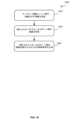
図15は第1の例示的な方法1500を示す。第1の例示的な方法1500は、どの出力ポート422がどの電気手術チャネルに接続されるかを制御する電気手術制御ユニット406によって実現されてもよい。この第1の例示的な方法1500では、制御ユニットは、電気手術ネットワーク404の全て又は一部のリンクを選択的に有効及び無効にすることで、電気手術出力装置と選択された組み合わせの電気手術接続ユニットの出力ポートとの間に電気手術接続を確立させるように構成される。方法1500はブロック1502において開始する。ブロック1502では、どの電気手術接続ユニットがどの電気手術チャネルに接続されるべきかを示す情報を電気手術制御ユニット406が受信する。電気手術ネットワークを介して伝達される1つだけの電気手術チャネルがある場合、どの電気手術接続ユニットがどの電気手術チャネルに接続されるべきかを示す情報は、どの電気手術接続ユニットが電気手術器具に接続されているかと、これら電気手術接続ユニットのうちどれが電気手術チャネルによって制御又は作動されるべきかと、を示す情報を含んでもよい。電気手術ネットワークを介して伝達できる複数の電気手術チャネルがある場合、当該情報は、これら電気手術器具のうちどれがどの電気手術チャネルに制御又は接続されるべきかを示す情報をさらに備えてもよい。一旦当該情報が受信されると、方法1500はブロック1504に進む。 FIG. 15 shows a first
ブロック1504では、電気手術制御ユニット406は、所望の電気手術接続ユニットを所望の電気手術チャネルに接続可能とするために有効にすべき電気手術ネットワークのリンク(及び/又はその一部)を特定する。電気手術ネットワークを介して伝達される電気手術チャネルが1つだけある場合、電気手術ネットワークのリンクは、これらリンクが所望のチャネルを所望の電気手術接続ユニットに接続するよう要求されているかどうかに基づいて、これらリンクの全体において有効/作動状態又は無効/非作動状態のいずれかになる。図7のシステム700を第1の例として、第2アーム402Bの電気手術接続ユニットに接続されるべき電気手術チャネルが1つある場合、制御ユニットは、リンク706のみを作動状態にすべきで且つその他のリンク704及び708は非作動状態又は無効にできる、と特定してもよい。第2の例のシステム900において、第2アーム402Bの電気手術接続ユニットに接続されるべき電気手術チャネルが1つある場合、制御ユニットは、リンク906及び902のみを作動状態にする必要があり且つその他のリンクは非作動状態にできる、と特定してもよい。 At
しかし、電気手術ネットワークが複数の電気手術チャネルを伝達できる場合、制御ユニットは、どのリンクを作動状態にすべきか、さらに、各リンクの全てを必要とするわけではないときにこれらリンクのどの部分を作動状態にすべきか、を特定してもよい。図10のシステム1000を例として、2つの電気手術チャネルがあり、そのうち、第1電気手術チャネルが各リンクの最初の2本のワイヤに関連づけられ且つ第2電気手術チャネルが各リンクの残りの2本のワイヤに関連づけられ且つ第1アーム402Aの第1電気手術接続ユニットが第1電気手術チャネルに接続されるべきであり且つ第2アーム402Bの電気手術接続ユニットが第2電気手術チャネルに接続されるべきである場合、電気手術制御ユニット406は、リンク1002のうち全てが作動状態になるべきであり且つリンク1004のうち最初の2本のワイヤのみが作動状態になるべきであり且つリンク1006のうちいずれも作動状態になるべきではない、と特定してもよい。 However, if the electrosurgical network is capable of carrying multiple electrosurgical channels, the control unit may decide which links to activate and which portions of each link to activate when not all of each link is needed. You may also specify whether it should be activated. Using the
一旦電気手術制御ユニット406が、所望の電気手術接続ユニットを所望の電気手術チャネルに接続可能にするために有効にすべき電気手術ネットワーク404のリンク(及び/又はその一部)を特定すると、方法1500はブロック1506に進む。 Once
ブロック1506では、電気手術制御ユニット406は、電気手術出力装置(例えば、電気手術器414)及び/又は電気手術接続ユニット416に制御信号を送信することで、特定されたリンク(及び/又はその一部)を有効にする。例えば、上記第1の1つのチャネルの例において、電気手術制御ユニット406は、電気手術分配ユニット710に制御信号を送信することでリンク706を作動状態にし且つリンク704、708を非作動状態にするように構成されてもよい。また、上記第2の1つのチャネルの例において、電気手術制御ユニット406は、第1アーム402Aの電気手術接続ユニット416に制御信号を送信することで入力ポート418が第2出力ポート912に接続されるように構成されてもよい。この接続の結果、リンク904が無効になってもよい。上記複数のチャネルの例において、電気手術制御ユニット406は、第2アーム402Bの電気手術接続ユニット416に制御信号を送信することで、入力ポート418の最初の2本のワイヤ及び出力ポート1012の最初の2本のワイヤ間を接続するように構成されてもよい。電気手術制御ユニット406によって送信される制御信号は、電気手術出力装置又は電気手術接続ユニットによって感知可能な任意の形状を有してもよい。 At
図16は第2の例示的な方法1600を示す。第2の例示的な方法1600は、どの出力ポート422がどの電気手術チャネルに接続されるかを制御する電気手術制御ユニット406によって実現されてもよい。この第2の例示的な方法1600では、制御ユニットは、選択された電気手術接続ユニットの入力ポート及び出力ポート間の電気接続を有効にすることで、電気手術出力装置と選択された組み合わせの電気手術接続ユニットの出力ポートとの間で電気手術接続を確立させるように、構成される。方法1600はブロック1602において開始する。ブロック1602では、どの電気手術接続ユニットがどの電気手術チャネルに接続されるべきかを示す情報を電気手術制御ユニット406が受信する。電気手術ネットワークを介して伝達される電気手術チャネルが1つだけある場合、どの電気手術接続ユニットがどの電気手術チャネルに接続されるべきかを示す情報は、どの電気手術接続ユニットが電気手術器具に接続されているかと、これら電気手術接続ユニットのうちどれが電気手術チャネルによって制御又は作動されるべきかと、を示す情報を含んでもよい。電気手術ネットワークを介して伝達できる複数の電気手術チャネルがある場合、当該情報は、電気手術器具のうちどれがどの電気手術チャネルに制御又は接続されるべきかを示す情報をさらに含んでもよい。一旦当該情報が受信されると、方法1600はブロック1604に進む。 FIG. 16 shows a second
ブロック1604では、電気手術制御ユニット406は、確立させるべき入力ポート-出力ポート間の接続を特定する。電気手術ネットワークを介して伝達される電気手術チャネルが1つだけある場合、入力ポート及び出力ポート間の接続がその全体において有効又は無効のいずれかになる。図7のシステム700を第1の例とし、第2アーム402Bの電気手術接続ユニットに接続されるべき1つの電気手術チャネルがある場合、制御ユニットは、第2アーム402Bの電気手術接続ユニットの入力ポート及び出力ポート間の接続のみが有効になるべきである、と特定してもよい。第2の例のシステム900において、第2アーム402Bの電気手術接続ユニットに接続されるべき1つの電気手術チャネルがある場合、制御ユニットは、第2アーム402Bの電気手術接続ユニットの入力ポート及び出力ポート間の接続のみが有効になるべきである、と特定してもよい。 At
しかし、電気手術ネットワークが複数の電気手術チャネルを伝達できる場合、制御ユニットは、入力ポートのうちどの部分が所望の出力ポートに接続されるべきかを特定する必要があると考えられる。図10のシステム1000を例とし、2つの電気手術チャネルがあり、そのうち、第1電気手術チャネルが各リンクの最初の2本のワイヤに関連づけられ且つ第2電気手術チャネルが各リンクの残りの2本のワイヤに関連づけられ且つ第1アーム402Aの第1電気手術接続ユニットが第1電気手術チャネルに接続されるべきであり且つ第2アーム402Bの電気手術接続ユニットが第2電気手術チャネルに接続されるべきである場合、電気手術制御ユニット406は、第2アーム402Bの電気手術接続ユニットの入力ポート418の最初の2本のワイヤ及び出力ポート422間の接続が有効になるべきであり且つ第1アーム402Aの電気手術接続ユニット416の入力ポート418の最後の2本のワイヤ及び出力ポート422間の接続が有効になるべきである、と特定してもよい。 However, if the electrosurgical network can carry multiple electrosurgical channels, the control unit would need to specify which portion of the input ports should be connected to the desired output port. Taking the
一旦電気手術制御ユニット406が、所望の出力ポートを所望の電気手術チャネルに接続可能にするために有効にすべき入力ポート-出力ポート間の接続を特定すると、方法1600はブロック1606に進む。 Once
ブロック1606では、電気手術制御ユニット406は電気手術接続ユニット416に制御信号を送信することで、特定された入力ポート-出力ポート間の接続を有効にする。例えば、上記第1の1つのチャネルの例において、電気手術制御ユニット406は、第2アーム402Bの電気手術接続ユニット416に制御信号を送信することで入力ポート418及び出力ポート422間の接続を有効にするように構成されてもよい。また、上記第2の1つのチャネルの例において、電気手術制御ユニット406は、第2アーム402Bの電気手術接続ユニット416に制御信号を送信することで入力ポート418及び出力ポート422間の接続を有効にするように構成されてもよい。上記複数のチャネルの例において、電気手術制御ユニット406は、第2アーム402Bの電気手術接続ユニット416に制御信号を送信することで入力ポート418の最初の2本のワイヤ及び出力ポート422間を接続し、且つ、第1アーム402Aの電気手術接続ユニット416に制御信号を送信することで入力ポート418の最後の2本のワイヤ及び出力ポート422間を接続するように、構成されてもよい。電気手術制御ユニット406によって送信される制御信号は、電気手術接続ユニットによって感知可能な任意の形状を有してもよい。 At
さらに別の例示的な方法(不図示)では、図15及び図16の方法1500及び1600を組み合わせてもよい。これにより、電気手術制御ユニット406は、電気手術ネットワークの選択的なリンク(及び/又はその一部)を有効にし且つ選択された電気手術接続ユニットの入力ポート及び出力ポート間の接続を確立させる制御信号を生成する。 Yet another exemplary method (not shown) may combine
図17を参照すると、例示的な方法1700が示されている。例示的な方法1700は、複数のチャネルが電気手術ネットワークのリンクのワイヤに動的にマッピングされる図14のシステム1400の電気手術MUX1434とスイッチングユニット1452とを制御する電気手術制御ユニット406によって実現されてもよい。方法1700はブロック1702において開始する。ブロック1702では、電気手術器具が特定のチャネルによって制御されるべきであることを示す情報を電気手術制御ユニット406が受信する。当該情報は、電気手術器具がアーム402A、402B、及び402Cに取り付けられたのに呼応して受信されてもよい。例えば、場合によっては、電気手術器具がアームに取り付けられたことが(例えば、アームによって)検出されたときに、ユーザは、どのチャネルを使ってその電気手術器具を制御するかを選択するよう求められてもよい。その後、当該情報は制御ユニットに送られる。或いは、当該情報は、システムのアームに取り付けられた電気手術器具に送られるべき駆動電気手術信号の生成をユーザが引き起こしたのに呼応して受信されてもよい。一旦当該情報が受信されると、方法1700はブロック1704に進む。 Referring to FIG. 17, an
ブロック1704では、電気手術制御ユニットは、特定された電気手術チャネルに関連づけられた電気手術信号を電気手術ネットワークを介して伝達するために使用可能であり且つ電気手術MUX1434に接続された、電気手術リンクのワイヤを特定する。このワイヤ特定は、電気手術MUX1434に接続された電気手術リンクの不使用ワイヤを特定することと、不使用ワイヤのうち1本以上のワイヤであって特定された電気手術チャネルに割り当てられるべき1本以上のワイヤを選択することと、を備える。上記のように、チャネルに割り当てられる電気手術ワイヤの数は、電気手術ネットワークを介して伝達されるべきチャネルの電気手術信号の数に基づく。場合によっては、1つだけの電気手術信号(駆動電気手術信号)が単極の電気手術チャネルに対して電気手術ネットワークを介して伝達され、複数の電気手術信号(駆動電気手術信号及び戻り電気手術信号)が双極の電気手術チャネルに対して電気手術ネットワークを介して伝達される。この場合、1本だけのワイヤが単極のチャネルに割り当てられ、2本のワイヤが双極のチャネルに割り当てられる。一旦電気手術制御ユニット406が、特定された電気手術チャネルに割り当てられるべき電気手術リンクのワイヤを特定すると、方法1700はブロック1706に進む。 At
ブロック1706では、電気手術制御ユニット406は、1つの制御信号又は複数の制御信号を電気手術MUX1434に送信することで所望の電気手術チャネルを特定されたワイヤにマッピングする。また、当該制御ユニットは、1つの制御信号又は複数の制御信号を適切な電気手術接続ユニット416に送信することで入力ポート418の特定されたワイヤを適切な出力ポート422、1222にマッピングする。制御信号は、電気手術MUX1434と電気手術接続ユニット416とによって感知される任意の好適な形状を有してもよい。 At
特定された電気手術チャネルをサポートする不使用ワイヤの必要数を電気手術制御ユニット406がブロック1704において特定できない場合、電気手術制御ユニット406は依頼を断わってもよい。これは、多数の電気手術ワイヤ又は導体が1つ以上の他の電気手術チャネルにすでに割り当てられているからであろう。こういった場合が発生しやすいか否かは、各ネットワークリンク内の電気手術ワイヤ又は導体の数と同時使用可能な電気手術器具の数とに依存する。電気手術ネットワークの各リンクが4本の電気手術ワイヤ又は導体を備える電気手術システムであれば、同時に4つまでの単極の電気手術チャネル、同時に2つの双極の電気手術チャネル、又は同時に1つの双極の電気手術チャネル及び2つの単極の電気手術チャネルをサポートする。この電気手術システムは、外科医が最大2つの手術器具を同時に制御できる外科医1人体制にとって十分であると思われる。しかし、この電気手術システムは、それぞれの外科医が最大2つの手術器具を同時に制御できる外科医2人体制にとっては不十分であるかもしれない。ただ、外科医2人体制は、現在では非常に可能性の低いシナリオである。なぜなら、4つの駆動電気手術信号が何らかのかたちで同時に干渉又はクロスカップリングするリスクが非常に高く、これにより患者に対して重大な影響を及ぼし得るからである。 If
上記の電気手術接続ユニットのうちいずれも、患者電極に接続可能な追加的なポート(不図示)も備えてもよい。この追加的なポートから戻り電気手術信号を受信する。戻り電極から受信された戻り電気手術信号は、双極の電気手術器具から受信された戻り電気手術信号と同様に、電気手術ネットワーク404を介して送信される。これにより、患者電極が電気手術器の代わりに電気手術接続ユニットに接続できる。これは、電気手術器が患者に近接していない又はケーブルを介して到達するには不便な場所に位置する状況において有利であると思われる。上記の実施形態のうちいずれにおいても、当該電気手術接続ユニットの対応する出力ポート422と同一の方法でこの追加的なポートは取り扱われる。具体的には、追加的なポートは、上記のように、入力ポート418に恒久的に接続されてもよく、又は、入力ポート418に切り替え可能に接続されてもよい。 Any of the electrosurgical connection units described above may also include additional ports (not shown) connectable to patient electrodes. A return electrosurgical signal is received from this additional port. Return electrosurgical signals received from return electrodes are transmitted over
本出願人は、本明細書に説明する個別の特徴を単独で、また、それら2つ以上の特徴の任意の組み合わせとして、ここに開示する。ただし、本明細書に開示された何らかの問題がそれらの特徴又はその組み合わせによって解決されるか否かに関係なく、それらの特徴又はその組み合わせを本明細書全体に基づき当業者にとって周知の一般的知識を踏まえて実行できる程度とする。上述の説明に鑑み、当業者にとって明白であるように、本発明の範囲内でさまざまな改変を加えることが可能である。
なお、本発明は、実施の態様として以下の内容を含む。
[態様1]
電気手術システム(400、600、700、800、900、1000、1100、1200、1300、1400)であって、
複数の電気手術接続ユニット(416)であって、各電気手術接続ユニットが、電気手術チャネルに接続可能な入力ポート(418)と電気手術器具(410)に接続可能な出力ポート(422)と備え、前記入力ポート(418)を前記出力ポート(422)に接続するように構成された、複数の電気手術接続ユニット(416)と、
電気手術出力装置(414、710、810、1110、1434)を介して前記電気手術接続ユニット(416)の前記入力ポート(418)を電気手術チャネルに接続する複数の電気手術リンクを備える電気手術ネットワーク(404)と、
1つ以上の制御信号を前記電気手術接続ユニット(416)及び/又は前記電気手術出力装置(414、710、810、1110、1434)に送信することで、選択された組み合わせの電気手術接続ユニット(416)の前記出力ポート(422)が前記電気手術チャネルに接続されるように構成された制御ユニット(406)と、
を備える電気手術システム。
[態様2]
態様1に記載の電気手術システム(400、600、700、800、900、1000、1100、1300、1400)において、各電気手術接続ユニット(416)は前記入力ポート(418)と前記出力ポート(422)との間にスイッチングユニット(426)をさらに備え、前記スイッチングユニット(426)は制御信号に反応して前記入力ポート(418)を前記出力ポート(422)に制御可能に接続するように構成されている、電気手術システム。
[態様3]
態様1又は2に記載の電気手術システム(400、600、700、800、900、1000、1100)において、前記制御ユニット(406)によって送信された前記1つ以上の制御信号により、選択された組み合わせの電気手術リンクが作動状態になり且つ他の全ての電気手術リンクが非作動状態になる、電気手術システム。
[態様4]
態様1から3のいずれかに記載の電気手術システム(900、1000、1100)において、前記電気手術リンクは前記電気手術接続ユニット(416)のうち少なくとも2つを前記電気手術チャネルにデイジーチェーン構成で接続する、電気手術システム。
[態様5]
態様4に記載の電気手術システム(900、1000、1100)において、少なくとも1つの電気手術接続ユニット(416)は別の電気手術接続ユニット(416)の前記入力ポート(418)に電気手術リンクを介して接続された第2出力ポート(912)をさらに備え、前記少なくとも1つの電気手術接続ユニット(416)は前記入力ポート(418)を前記第2出力ポート(912)に電気的に接続するように構成されている、電気手術システム。
[態様6]
態様5に記載の電気手術システム(900、1000、1100)において、前記少なくとも1つの電気手術接続ユニット(416)は前記入力ポート(418)と前記第2出力ポート(912)との間に位置するスイッチングユニット(914)をさらに備え、前記スイッチングユニット(914)は制御信号に反応して前記入力ポート(418)を前記第2出力ポート(912)に制御可能に接続するように構成されている、電気手術システム。
[態様7]
態様1から6のいずれかに記載の電気手術システム(600、700、800)において、前記電気手術リンクは前記電気手術接続ユニット(416)のうち少なくとも2つを前記電気手術チャネルにスター型構成で接続する、電気手術システム。
[態様8]
態様1から7のいずれかに記載の電気手術システム(1200、1300)において、前記電気手術システムは第2電気手術ネットワークをさらに備え、前記第2電気手術ネットワークは、前記電気手術接続ユニット(416)の前記入力ポート(418)を第2電気手術チャネルに接続する複数の電気手術リンクを備える、電気手術システム。
[態様9]
態様8に記載の電気手術システム(1200、1300)において、前記電気手術チャネル及び前記第2電気手術チャネルは同一の電気手術器によって制御される、電気手術システム。
[態様10]
態様8に記載の電気手術システム(1200、1300)において、前記電気手術チャネル及び前記第2電気手術チャネルは異なる電気手術器によって制御される、電気手術システム。
[態様11]
態様8から10のいずれかに記載の電気手術システム(1200)において、前記電気手術接続ユニット(416)のうち少なくとも1つは第2出力ポート(1222)をさらに備え、前記少なくとも1つの電気手術接続ユニット(416)は前記電気手術チャネルを前記出力ポート(422)に接続し且つ前記第2電気手術チャネルを前記第2出力ポート(1222)に接続するように構成されている、電気手術システム。
[態様12]
態様8から11のいずれかに記載の電気手術システム(1200、1300)において、前記第1及び第2電気手術チャネルのうち一方は双極の電気手術チャネルであり、前記第1及び第2電気手術チャネルのうち他方は単極の電気手術チャネルである、電気手術システム。
[態様13]
態様8から11のいずれかに記載の電気手術システム(1200、1300)において、前記第1及び第2電気手術チャネルは双極の電気手術チャネルである、電気手術システム。
[態様14]
態様8から11のいずれかに記載の電気手術システム(1200、1300)において、前記第1及び第2電気手術チャネルは単極の電気手術チャネルである、電気手術システム。
[態様15]
態様8から10のいずれかに記載の電気手術システム(1300)において、前記電気手術接続ユニットのうち少なくとも1つは、前記入力ポート(418)と前記出力ポート(422)との間に位置するスイッチングユニット(1302)を備え、前記スイッチングユニット(1302)は、制御信号に反応して前記電気手術チャネル及び前記第2電気手術チャネルのうち一方を前記出力ポートに制御可能に接続するように構成されている、電気手術システム。
[態様16]
態様15に記載の電気手術システム(1300)において、前記電気手術チャネル及び前記第2電気手術チャネルは同一タイプのものである、電気手術システム。
[態様17]
態様1に記載の電気手術システム(1400)において、前記電気手術ネットワーク(404)の各リンクは複数の電気手術導体を備え、前記電気出力装置は電気手術マルチプレクサ(1434)であり、前記電気手術マルチプレクサ(1434)は、複数の電気手術チャネルに接続され、制御信号に反応して前記複数の電気手術チャネルのうち1つ以上を前記電気手術導体のうち1本以上に動的に接続するように構成されている、電気手術システム。[態様18]
態様17に記載の電気手術システム(1400)において、各電気手術接続ユニット(416)は前記入力ポート(418)と前記出力ポート(422)との間にスイッチングユニット(1452)を備え、前記スイッチングユニット(1452)は制御信号に反応して前記電気手術リンクの1本以上の電気手術導体を前記出力ポート(422)に制御可能に接続するように構成されている、電気手術システム。
[態様19]
態様18に記載の電気手術システム(1400)において、前記電気手術接続ユニット(416)のうち少なくとも1つのユニットは第2出力ポート(1222)を備え、前記少なくとも1つの電気手術接続ユニット(416)の前記スイッチングユニットは前記制御信号に反応して前記電気手術リンクの1本以上の電気手術導体を前記第2出力ポート(1222)に制御可能に接続するように構成されている、電気手術システム。
[態様20]
態様17から19のいずれかに記載の電気手術システム(1400)において、前記電気手術チャネルのうち少なくとも1つは単極の電気手術チャネルであり、前記電気手術チャネルのうち少なくとも1つは双極の電気手術チャネルである、電気手術システム。
[態様21]
態様17から19のいずれかに記載の電気手術システム(1400)において、前記第1及び第2電気手術チャネルは双極の電気手術チャネルである、電気手術システム。
[態様22]
態様17から19のいずれかに記載の電気手術システム(1400)において、前記第1及び第2電気手術チャネルは単極の電気手術チャネルである、電気手術システム。
[態様23]
態様1から22のいずれかに記載の電気手術システム(400、600、700、800、900、1000、1100、1200、1300、1400)において、前記制御ユニットは、1つ以上の制御信号を前記電気手術接続ユニット(416)及び/又は前記電気手術出力装置(414、710、810、1110、1434)に送信することで1つだけの電気手術接続ユニット(416)の前記出力ポートを前記電気手術チャネルに接続するように構成されている、電気手術システム。
[態様24]
態様1から23のいずれかに記載の電気手術システム(400、600、700、800、900、1000、1100、1200、1300、1400)において、前記電気手術システムは、前記電気手術チャネルを駆動するように構成された電気手術器(414)をさらに備える、電気手術システム。
[態様25]
態様24に記載の電気手術システム(400、600、700、800、900、1000、1100、1200、1300、1400)において、前記制御ユニット(406)はさらに、前記電気手術器(414)の場所を検出し、前記検出に基づいて、前記1つ以上の制御信号を送信するように構成されている、電気手術システム。
[態様26]
態様1から25のいずれかに記載の電気手術システム(400、600、700、800、900、1000、1100、1200、1300、1400)において、前記電気手術システムは複数のロボットアーム(402A、402B、402C)をさらに備え、各ロボットアーム(402A、402B、402C)は、
手術器具を前記ロボットアームに取り外し可能に取り付けるための取付構造体(408)と、
前記ロボットアームに取り付けた電気手術器具を電気手術チャネルに接続するための前記電気手術接続ユニット(416)のうちの1つのユニットと、を備える、電気手術システム。
[態様27]
態様26に記載の電気手術システム(400、600、700、800、900、1000、1100、1200、1300、1400)において、各ロボットアームは、一連の中間関節接合ロボットアームリンクを介して遠位ロボットアームリンクに接続されたロボットアーム基台を備える、電気手術システム。
[態様28]
手術用ロボットアーム用の電気手術接続ユニット(416)であって、
電気手術出力装置から駆動電気手術信号を受信するように構成された入力ポート(418)と、
駆動電気手術信号を電気手術入力装置に出力するように構成された出力ポート(422)と、
前記入力ポート(418)と前記出力ポート(422)との間に位置するスイッチングユニット(426、1302、1452)であって、制御信号に反応して前記入力ポートを前記出力ポートに制御可能に接続することで、前記入力ポート(418)にて受信された駆動電気信号が前記出力ポート(422)にて出力されるように構成されたスイッチングユニット(426、1302、1452)と、
を備える電気手術接続ユニット。
[態様29]
態様28に記載の電気手術接続ユニット(416)において、前記電気手術接続ユニットは、前記駆動電気手術信号を別の電気手術入力装置に出力するための第2出力ポート(812、912)をさらに備える、電気手術接続ユニット。
[態様30]
態様29に記載の電気手術接続ユニット(416)において、前記他の電気手術入力装置は、別の手術用ロボットアームに接続された別の電気手術接続ユニット(416)である、電気手術接続ユニット。
[態様31]
態様29又は30に記載の電気手術接続ユニット(416)において、前記電気手術接続ユニットは、制御信号に反応して前記入力ポート(418)を前記第2出力ポート(812、912)に制御可能に接続するように構成された第2スイッチングユニット(814、914)をさらに備える、電気手術接続ユニット。
[態様32]
態様28に記載の電気手術接続ユニット(416)において、前記入力ポートは、前記入力ポート(418)の第1電気手術導体上で前記駆動電気手術信号を受信し且つ前記入力ポート(418)の第2電気手術導体上で第2駆動電気手術信号を受信するように構成され、前記スイッチングユニット(1302)は制御信号に反応して前記第1及び第2電気手術導体のうち一方を前記出力ポート(422)に制御可能に接続するように構成されている、電気手術接続ユニット。
[態様33]
態様28に記載の電気手術接続ユニット(416)において、前記入力ポート(418)は複数の電気手術導体を備え、前記制御ユニット(1452)は制御信号に反応して前記複数の電気手術導体のサブセットを前記出力ポート(422)に制御可能に接続するように構成されている、電気手術接続ユニット。
[態様34]
態様28から33のいずれかに記載の電気手術接続ユニット(416)において、前記出力ポート(422)はさらに戻り電気手術信号を受信するように構成され、前記入力ポート(418)はさらに戻り電気手術信号を出力するように構成され、前記スイッチングユニット(426)が前記入力ポート(418)を前記出力ポート(422)に接続するときに、前記入力ポート(418)にて受信された駆動電気手術信号は前記出力ポート(422)にて出力され、前記出力ポート(422)にて受信された対応する戻り電気手術信号は前記入力ポート(418)にて出力される、電気手術接続ユニット。
[態様35]
態様28から34のいずれかに記載の電気手術接続ユニット(416)において、前記出力ポート(422)は、前記手術用ロボットアームに取り付けられた電気手術器具に接続されるように構成されている、電気手術接続ユニット。
[態様36]
態様28から35のいずれかに記載の電気手術接続ユニット(416)において、前記入力ポート(418)は、電気手術出力装置(414)に接続された電気手術ネットワーク(404)に接続されるように構成されている、電気手術接続ユニット。
[態様37]
態様28から36のいずれかに記載の前記電気手術接続ユニット(416)を備える、手術用ロボットアーム(402A、402B、402C)。Applicants hereby disclose each individual feature described herein individually and as any combination of two or more of those features. However, regardless of whether or not any problem disclosed herein is solved by those features or combinations thereof, such features or combinations thereof may be used as general knowledge known to those skilled in the art based on this specification as a whole. to the extent that it can be carried out based on Various modifications are possible within the scope of the invention, as will be apparent to a person skilled in the art in view of the foregoing description.
In addition, this invention includes the following contents as a mode of implementation.
[Aspect 1]
An electrosurgical system (400, 600, 700, 800, 900, 1000, 1100, 1200, 1300, 1400) comprising:
A plurality of electrosurgical connection units (416), each electrosurgical connection unit comprising an input port (418) connectable to an electrosurgical channel and an output port (422) connectable to an electrosurgical instrument (410). , a plurality of electrosurgical connection units (416) configured to connect said input port (418) to said output port (422);
An electrosurgical network comprising a plurality of electrosurgical links connecting said input port (418) of said electrosurgical connection unit (416) to an electrosurgical channel via electrosurgical output devices (414, 710, 810, 1110, 1434). (404) and
Selected combinations of electrosurgical connection units ( a control unit (406) configured such that said output port (422) of 416) is connected to said electrosurgical channel;
An electrosurgical system comprising:
[Aspect 2]
The electrosurgical system (400, 600, 700, 800, 900, 1000, 1100, 1300, 1400) of
[Aspect 3]
3. The electrosurgical system (400, 600, 700, 800, 900, 1000, 1100) of
[Aspect 4]
4. The electrosurgical system (900, 1000, 1100) of any of aspects 1-3, wherein the electrosurgical link daisy-chains at least two of the electrosurgical connection units (416) to the electrosurgical channel. Connected, electrosurgical system.
[Aspect 5]
5. The electrosurgical system (900, 1000, 1100) of aspect 4, wherein at least one electrosurgical connection unit (416) is connected to said input port (418) of another electrosurgical connection unit (416) via an electrosurgical link. and further comprising a second output port (912) connected to the at least one electrosurgical connection unit (416) such that the at least one electrosurgical connection unit (416) electrically connects the input port (418) to the second output port (912). configured electrosurgical system.
[Aspect 6]
6. The electrosurgical system (900, 1000, 1100) of aspect 5, wherein said at least one electrosurgical connection unit (416) is located between said input port (418) and said second output port (912) further comprising a switching unit (914), said switching unit (914) being configured to controllably connect said input port (418) to said second output port (912) in response to a control signal; electrosurgical system.
[Aspect 7]
7. The electrosurgical system (600, 700, 800) of any of aspects 1-6, wherein the electrosurgical link connects at least two of the electrosurgical connection units (416) to the electrosurgical channel in a star configuration. Connected, electrosurgical system.
[Aspect 8]
8. The electrosurgical system (1200, 1300) of any of aspects 1-7, wherein said electrosurgical system further comprises a second electrosurgical network, said second electrosurgical network being connected to said electrosurgical connection unit (416) an electrosurgical system comprising a plurality of electrosurgical links connecting said input port (418) of to a second electrosurgical channel.
[Aspect 9]
9. The electrosurgical system (1200, 1300) of aspect 8, wherein said electrosurgical channel and said second electrosurgical channel are controlled by the same electrosurgical instrument.
[Aspect 10]
9. The electrosurgical system (1200, 1300) of aspect 8, wherein said electrosurgical channel and said second electrosurgical channel are controlled by different electrosurgical instruments.
[Aspect 11]
11. The electrosurgical system (1200) of any of aspects 8-10, wherein at least one of said electrosurgical connection units (416) further comprises a second output port (1222), said at least one electrosurgical connection An electrosurgical system, wherein unit (416) is configured to connect said electrosurgical channel to said output port (422) and to connect said second electrosurgical channel to said second output port (1222).
[Aspect 12]
12. The electrosurgical system (1200, 1300) of any of aspects 8-11, wherein one of said first and second electrosurgical channels is a bipolar electrosurgical channel, said first and second electrosurgical channels the other of which is a monopolar electrosurgical channel.
[Aspect 13]
12. The electrosurgical system (1200, 1300) of any of aspects 8-11, wherein the first and second electrosurgical channels are bipolar electrosurgical channels.
[Aspect 14]
12. The electrosurgical system (1200, 1300) of any of aspects 8-11, wherein said first and second electrosurgical channels are monopolar electrosurgical channels.
[Aspect 15]
11. The electrosurgical system (1300) of any of aspects 8-10, wherein at least one of said electrosurgical connection units is a switching device located between said input port (418) and said output port (422). a unit (1302), wherein the switching unit (1302) is configured to controllably connect one of the electrosurgical channel and the second electrosurgical channel to the output port in response to a control signal; There is an electrosurgical system.
[Aspect 16]
16. The electrosurgical system (1300) of aspect 15, wherein the electrosurgical channel and the second electrosurgical channel are of the same type.
[Aspect 17]
The electrosurgical system (1400) of
18. The electrosurgical system (1400) of aspect 17, wherein each electrosurgical connection unit (416) comprises a switching unit (1452) between said input port (418) and said output port (422), said switching unit (1452) is an electrosurgical system configured to controllably connect one or more electrosurgical conductors of said electrosurgical link to said output port (422) in response to a control signal.
[Aspect 19]
19. The electrosurgical system (1400) of aspect 18, wherein at least one of said electrosurgical connection units (416) comprises a second output port (1222), and wherein said at least one electrosurgical connection unit (416) An electrosurgical system, wherein said switching unit is configured to controllably connect one or more electrosurgical conductors of said electrosurgical link to said second output port (1222) in response to said control signal.
[Aspect 20]
20. The electrosurgical system (1400) of any of aspects 17-19, wherein at least one of said electrosurgical channels is a monopolar electrosurgical channel and at least one of said electrosurgical channels is a bipolar electrosurgical channel. An electrosurgical system that is a surgical channel.
[Aspect 21]
20. The electrosurgical system (1400) of any of aspects 17-19, wherein the first and second electrosurgical channels are bipolar electrosurgical channels.
[Aspect 22]
20. The electrosurgical system (1400) of any of aspects 17-19, wherein the first and second electrosurgical channels are monopolar electrosurgical channels.
[Aspect 23]
23. The electrosurgical system (400, 600, 700, 800, 900, 1000, 1100, 1200, 1300, 1400) of any of aspects 1-22, wherein said control unit outputs one or more control signals to said electrical Sending to surgical connection unit (416) and/or said electrosurgical output device (414, 710, 810, 1110, 1434) allows said output port of only one electrosurgical connection unit (416) to be connected to said electrosurgical channel. An electrosurgical system configured to connect to an electrosurgical system.
[Aspect 24]
24. The electrosurgical system of any of aspects 1-23 (400, 600, 700, 800, 900, 1000, 1100, 1200, 1300, 1400), wherein said electrosurgical system is configured to drive said electrosurgical channel. An electrosurgical system, further comprising an electrosurgical unit (414) configured to:
[Aspect 25]
25. The electrosurgical system (400, 600, 700, 800, 900, 1000, 1100, 1200, 1300, 1400) according to aspect 24, wherein said control unit (406) further determines the location of said electrosurgical device (414). An electrosurgical system configured to detect and transmit the one or more control signals based on the detection.
[Aspect 26]
26. The electrosurgical system (400, 600, 700, 800, 900, 1000, 1100, 1200, 1300, 1400) of any of aspects 1-25, wherein said electrosurgical system comprises a plurality of robotic arms (402A, 402B, 402C), each robotic arm (402A, 402B, 402C):
a mounting structure (408) for removably mounting a surgical instrument to the robotic arm;
and one of said electrosurgical connection units (416) for connecting an electrosurgical instrument attached to said robotic arm to an electrosurgical channel.
[Aspect 27]
27. The electrosurgical system (400, 600, 700, 800, 900, 1000, 1100, 1200, 1300, 1400) according to aspect 26, wherein each robotic arm connects to a distal robotic arm via a series of intermediate articulating robotic arm links. An electrosurgical system comprising a robotic arm base connected to an arm link.
[Aspect 28]
An electrosurgical connection unit (416) for a surgical robotic arm, comprising:
an input port (418) configured to receive a driving electrosurgical signal from an electrosurgical output device;
an output port (422) configured to output a driving electrosurgical signal to an electrosurgical input device;
A switching unit (426, 1302, 1452) located between said input port (418) and said output port (422) for controllably connecting said input port to said output port in response to a control signal. a switching unit (426, 1302, 1452) configured to output at said output port (422) a driving electrical signal received at said input port (418);
An electrosurgical connection unit comprising:
[Aspect 29]
29. The electrosurgical connection unit (416) according to aspect 28, wherein said electrosurgical connection unit further comprises a second output port (812, 912) for outputting said driving electrosurgical signal to another electrosurgical input device , electrosurgical connection unit.
[Aspect 30]
30. The electrosurgical connection unit (416) according to aspect 29, wherein the other electrosurgical input device is another electrosurgical connection unit (416) connected to another surgical robotic arm.
[Aspect 31]
31. The electrosurgical connection unit (416) according to aspect 29 or 30, wherein said electrosurgical connection unit is controllable from said input port (418) to said second output port (812, 912) in response to a control signal An electrosurgical connection unit, further comprising a second switching unit (814, 914) configured to connect.
[Aspect 32]
29. The electrosurgical connection unit (416) according to aspect 28, wherein the input port receives the drive electrosurgical signal on a first electrosurgical conductor of the input port (418) and a second electrosurgical conductor of the input port (418). Configured to receive a second drive electrosurgical signal on two electrosurgical conductors, said switching unit (1302) is responsive to a control signal to switch one of said first and second electrosurgical conductors to said output port (1302). 422).
[Aspect 33]
29. The electrosurgical connection unit (416) according to aspect 28, wherein said input port (418) comprises a plurality of electrosurgical conductors and said control unit (1452) selects a subset of said plurality of electrosurgical conductors in response to a control signal. to said output port (422).
[Aspect 34]
34. The electrosurgical connection unit (416) of any of aspects 28-33, wherein said output port (422) is further configured to receive a return electrosurgical signal and said input port (418) is further configured to receive a return electrosurgical signal. a driving electrosurgical signal configured to output a signal received at said input port (418) when said switching unit (426) connects said input port (418) to said output port (422); is output at said output port (422) and a corresponding return electrosurgical signal received at said output port (422) is output at said input port (418).
[Aspect 35]
35. The electrosurgical connection unit (416) of any of aspects 28-34, wherein the output port (422) is configured to be connected to an electrosurgical instrument attached to the surgical robotic arm. Electrosurgical connection unit.
[Aspect 36]
36. The electrosurgical connection unit (416) according to any of aspects 28-35, wherein said input port (418) is connected to an electrosurgical network (404) connected to an electrosurgical output device (414). Configured electrosurgical connection unit.
[Aspect 37]
37. A surgical robotic arm (402A, 402B, 402C) comprising the electrosurgical connection unit (416) of any of aspects 28-36.
Claims (14)
Translated fromJapanese複数の電気手術接続ユニット(416)であって、各電気手術接続ユニットが、電気手術チャネルに接続可能な入力ポート(418)と電気手術器具(410)に接続可能な出力ポート(422)と備え、前記入力ポート(418)を前記出力ポート(422)に接続するように構成された、複数の電気手術接続ユニット(416)と、
前記電気手術接続ユニット(416)の前記入力ポート(418)を、電気手術出力装置(414)によって制御される電気手術チャネルに接続する複数の電気手術リンクを備える、電気手術ネットワーク(404)と、
前記電気手術接続ユニット(416)の前記入力ポート(418)を第2電気手術チャネルに接続する複数の電気手術リンクを備える、第2電気手術ネットワーク(1204)と、
1つ以上の制御信号を前記電気手術接続ユニット(416)に送信することで、第1の選択されたセットの電気手術接続ユニット(416)の各電気手術接続ユニット(416)の前記出力ポート(422)が前記電気手術チャネルに接続されるように、かつ/または、第2の選択されたセットの電気手術接続ユニット(416)の各電気手術接続ユニット(416)の前記出力ポート(422)が前記第2電気手術チャネルに接続されるように構成された制御ユニット(406)と、
を備え、
前記電気手術接続ユニットのうち少なくとも1つは、前記入力ポート(418)と前記出力ポート(422)との間に位置するスイッチングユニット(1302)を備え、前記スイッチングユニット(1302)は、制御信号に反応して前記電気手術チャネル及び前記第2電気手術チャネルのうち一方を前記出力ポートに制御可能に接続するように構成されている、
る電気手術システム。An electrosurgical system (1300) comprising:
A plurality of electrosurgical connection units (416), each electrosurgical connection unit comprising an input port (418) connectable to an electrosurgical channel and an output port (422) connectable to an electrosurgical instrument (410). , a plurality of electrosurgical connection units (416) configured to connect said input port (418) to said output port (422);
an electrosurgical network (404) comprising a plurality of electrosurgical links connecting the input port (418) of the electrosurgical connection unit (416) to an electrosurgical channel controlled by an electrosurgical output device (414);
a second electrosurgical network (1204) comprising a plurality of electrosurgical links connecting said input port (418) of said electrosurgical connection unit (416) to a second electrosurgical channel;
Sending one or more control signals to said electrosurgical connection unit (416) causes said output port ( 422) is connected to said electrosurgical channel, and/or said output port (422) of each electrosurgical connection unit (416) of a second selected set of electrosurgical connection units (416) is connected to said electrosurgical channel. a control unit (406) configured to be connected to the second electrosurgical channel;
with
At least one of said electrosurgical connection units comprises a switching unit (1302) located between said input port (418) and said output port (422), said switching unit (1302) being responsive to a control signal. configured to responsively controllably connect one of the electrosurgical channel and the second electrosurgical channel to the output port;
electrosurgical system.
手術器具を前記ロボットアームに取り外し可能に取り付けるための取付構造体(408)と、
前記ロボットアームに取り付けた電気手術器具を電気手術チャネルに接続するための前記電気手術接続ユニット(416)のうちの1つのユニットと、を備える、電気手術システム。The electrosurgical system (1300) of any one of claims 1 to 13, wherein said electrosurgical system further comprises a plurality of robotic arms (402A, 402B, 402C), each robotic arm (402A, 402B, 402C) )teeth,
a mounting structure (408) for removably mounting a surgical instrument to the robotic arm;
and one of said electrosurgical connection units (416) for connecting an electrosurgical instrument attached to said robotic arm to an electrosurgical channel.
Applications Claiming Priority (4)
| Application Number | Priority Date | Filing Date | Title |
|---|---|---|---|
| GB1803380.3 | 2018-03-01 | ||
| GB1803380.3AGB2571567B (en) | 2018-03-01 | 2018-03-01 | Electrosurgical network |
| JP2020545528AJP7194191B2 (en) | 2018-03-01 | 2019-02-28 | electrosurgery network |
| PCT/GB2019/050560WO2019166813A1 (en) | 2018-03-01 | 2019-02-28 | Electrosurgical network |
Related Parent Applications (1)
| Application Number | Title | Priority Date | Filing Date |
|---|---|---|---|
| JP2020545528ADivisionJP7194191B2 (en) | 2018-03-01 | 2019-02-28 | electrosurgery network |
Publications (1)
| Publication Number | Publication Date |
|---|---|
| JP2023022315Atrue JP2023022315A (en) | 2023-02-14 |
Family
ID=61903528
Family Applications (2)
| Application Number | Title | Priority Date | Filing Date |
|---|---|---|---|
| JP2020545528AActiveJP7194191B2 (en) | 2018-03-01 | 2019-02-28 | electrosurgery network |
| JP2022197054APendingJP2023022315A (en) | 2018-03-01 | 2022-12-09 | Electrosurgical network |
Family Applications Before (1)
| Application Number | Title | Priority Date | Filing Date |
|---|---|---|---|
| JP2020545528AActiveJP7194191B2 (en) | 2018-03-01 | 2019-02-28 | electrosurgery network |
Country Status (8)
| Country | Link |
|---|---|
| US (3) | US20210045797A1 (en) |
| EP (2) | EP3758642B1 (en) |
| JP (2) | JP7194191B2 (en) |
| CN (1) | CN111787881B (en) |
| AU (1) | AU2019226709B2 (en) |
| BR (1) | BR112020017816A2 (en) |
| GB (1) | GB2571567B (en) |
| WO (1) | WO2019166813A1 (en) |
Families Citing this family (22)
| Publication number | Priority date | Publication date | Assignee | Title |
|---|---|---|---|---|
| GB2571567B (en) | 2018-03-01 | 2022-03-09 | Cmr Surgical Ltd | Electrosurgical network |
| US11510720B2 (en)* | 2018-09-07 | 2022-11-29 | Cilag Gmbh International | Managing simultaneous monopolar outputs using duty cycle and synchronization |
| US11004557B2 (en)* | 2018-10-17 | 2021-05-11 | Us Patent Innovations, Llc | System and method for RFID identification of electrosurgical accessories |
| EP4340367A3 (en) | 2019-04-27 | 2024-04-24 | Huawei Technologies Co., Ltd. | An encoder, a decoder and corresponding methods of intra prediction |
| GB2586815B (en)* | 2019-09-03 | 2023-05-24 | Cmr Surgical Ltd | Electrosurgical network |
| US20220096175A1 (en)* | 2020-09-25 | 2022-03-31 | Duke University | Artificial training data collection system for rfid surgical instrument localization |
| US11911030B2 (en) | 2020-10-02 | 2024-02-27 | Cilag Gmbh International | Communication capability of a surgical device with component |
| US11672534B2 (en) | 2020-10-02 | 2023-06-13 | Cilag Gmbh International | Communication capability of a smart stapler |
| US11883022B2 (en) | 2020-10-02 | 2024-01-30 | Cilag Gmbh International | Shared situational awareness of the device actuator activity to prioritize certain aspects of displayed information |
| US11883052B2 (en)* | 2020-10-02 | 2024-01-30 | Cilag Gmbh International | End effector updates |
| US11830602B2 (en) | 2020-10-02 | 2023-11-28 | Cilag Gmbh International | Surgical hub having variable interconnectivity capabilities |
| US11748924B2 (en) | 2020-10-02 | 2023-09-05 | Cilag Gmbh International | Tiered system display control based on capacity and user operation |
| US11877792B2 (en)* | 2020-10-02 | 2024-01-23 | Cilag Gmbh International | Smart energy combo control options |
| US12213801B2 (en) | 2020-10-02 | 2025-02-04 | Cilag Gmbh International | Surgical visualization and particle trend analysis system |
| US11992372B2 (en) | 2020-10-02 | 2024-05-28 | Cilag Gmbh International | Cooperative surgical displays |
| US12064293B2 (en) | 2020-10-02 | 2024-08-20 | Cilag Gmbh International | Field programmable surgical visualization system |
| US11963683B2 (en) | 2020-10-02 | 2024-04-23 | Cilag Gmbh International | Method for operating tiered operation modes in a surgical system |
| US12016566B2 (en) | 2020-10-02 | 2024-06-25 | Cilag Gmbh International | Surgical instrument with adaptive function controls |
| US11877897B2 (en) | 2020-10-02 | 2024-01-23 | Cilag Gmbh International | Situational awareness of instruments location and individualization of users to control displays |
| US11510743B2 (en) | 2020-10-02 | 2022-11-29 | Cilag Gmbh International | Communication control for a surgeon controlled secondary display and primary display |
| US20240252261A1 (en)* | 2023-01-26 | 2024-08-01 | Covidien Lp | Surgical robotic system and method for cart power switchover |
| GB2629453A (en)* | 2023-04-28 | 2024-10-30 | Cmr Surgical Ltd | Electrosurgical connection unit |
Citations (6)
| Publication number | Priority date | Publication date | Assignee | Title |
|---|---|---|---|---|
| WO2001037745A1 (en)* | 1999-11-25 | 2001-05-31 | Ethicon Gmbh | Switching appliance for electrosurgical devices |
| US20010029315A1 (en)* | 2000-02-29 | 2001-10-11 | Tomohisa Sakurai | Surgical operation system |
| US20120239020A1 (en)* | 2011-03-15 | 2012-09-20 | Tyco Healthcare Group Lp | Geo-Location Addition to Electrosurgical Generator |
| JP2014533135A (en)* | 2011-10-05 | 2014-12-11 | メドトロニック・ゾーメド・インコーポレーテッド | Interface module that enables tissue stimulation and electrosurgical delivery via common surgical instruments |
| JP2015535193A (en)* | 2012-11-02 | 2015-12-10 | インテュイティブ サージカル オペレーションズ, インコーポレイテッド | Flux transmission connector and system, flux removal, and system and method for mapping a flux supply path |
| US20170189095A1 (en)* | 2015-12-31 | 2017-07-06 | Ethicon Endo-Surgery, Llc | Multiple port electrical isolation technique for surgical instruments |
Family Cites Families (26)
| Publication number | Priority date | Publication date | Assignee | Title |
|---|---|---|---|---|
| US20060095032A1 (en)* | 1999-11-16 | 2006-05-04 | Jerome Jackson | Methods and systems for determining physiologic characteristics for treatment of the esophagus |
| US6620157B1 (en)* | 2000-12-28 | 2003-09-16 | Senorx, Inc. | High frequency power source |
| US20100324550A1 (en)* | 2009-06-17 | 2010-12-23 | Nuortho Surgical Inc. | Active conversion of a monopolar circuit to a bipolar circuit using impedance feedback balancing |
| US8361067B2 (en)* | 2002-09-30 | 2013-01-29 | Relievant Medsystems, Inc. | Methods of therapeutically heating a vertebral body to treat back pain |
| US7883458B2 (en)* | 2003-06-27 | 2011-02-08 | Stryker Corporation | System for remotely controlling two or more medical devices |
| US20110125149A1 (en)* | 2007-02-06 | 2011-05-26 | Rizk El-Galley | Universal surgical function control system |
| AU2008217492B2 (en)* | 2007-02-25 | 2013-10-24 | Avent, Inc. | Methods for control of energy delivery to multiple energy delivery devices |
| US8641704B2 (en) | 2007-05-11 | 2014-02-04 | Medtronic Ablation Frontiers Llc | Ablation therapy system and method for treating continuous atrial fibrillation |
| US7834484B2 (en)* | 2007-07-16 | 2010-11-16 | Tyco Healthcare Group Lp | Connection cable and method for activating a voltage-controlled generator |
| US9050120B2 (en)* | 2007-09-30 | 2015-06-09 | Intuitive Surgical Operations, Inc. | Apparatus and method of user interface with alternate tool mode for robotic surgical tools |
| US20090276515A1 (en)* | 2008-05-02 | 2009-11-05 | Boston Scientific Scimed, Inc. | Multi-modality network for improved workflow |
| EP2502595B1 (en)* | 2008-05-05 | 2014-10-01 | Stryker Corporation | Control console for a surgical tool, the console capable of reading data from a memory integral with the tool from the console terminals over which power is sourced to the tool |
| US8418073B2 (en)* | 2009-03-09 | 2013-04-09 | Intuitive Surgical Operations, Inc. | User interfaces for electrosurgical tools in robotic surgical systems |
| US8382751B2 (en)* | 2009-09-10 | 2013-02-26 | Covidien Lp | System and method for power supply noise reduction |
| US20130138097A1 (en)* | 2010-01-29 | 2013-05-30 | Medtronic Ablation Frontiers Llc | System and method to detect patient return electrode connection in an rf ablation system |
| US20140180272A1 (en)* | 2012-11-02 | 2014-06-26 | Intuitive Surgical Operations, Inc. | Flux transmission connectors, systems, and methods |
| WO2015068697A1 (en)* | 2013-11-11 | 2015-05-14 | オリンパスメディカルシステムズ株式会社 | Treatment system |
| US10117702B2 (en)* | 2015-04-10 | 2018-11-06 | Ethicon Llc | Surgical generator systems and related methods |
| JP7123791B2 (en) | 2015-09-30 | 2022-08-23 | エシコン エルエルシー | Circuit topology for compound generator |
| US10932861B2 (en)* | 2016-01-14 | 2021-03-02 | Auris Health, Inc. | Electromagnetic tracking surgical system and method of controlling the same |
| US10582962B2 (en)* | 2016-01-23 | 2020-03-10 | Covidien Lp | System and method for harmonic control of dual-output generators |
| CN108697465A (en)* | 2016-02-23 | 2018-10-23 | 柯惠Lp公司 | Common connector for monopole and bipolar instrument |
| US11026757B2 (en)* | 2016-07-20 | 2021-06-08 | Intuitive Surgical Operations, Inc. | Surgical cannulas, and related systems and methods |
| JP2020517371A (en) | 2017-04-28 | 2020-06-18 | ストライカー・コーポレイション | Control console and accessory for RF nerve ablation and method for performing RF nerve ablation |
| EP4049603B1 (en) | 2017-06-15 | 2024-01-31 | Reach Surgical, Inc. | Electrosurgical systems |
| GB2571567B (en) | 2018-03-01 | 2022-03-09 | Cmr Surgical Ltd | Electrosurgical network |
- 2018
- 2018-03-01GBGB1803380.3Apatent/GB2571567B/enactiveActive
- 2019
- 2019-02-28WOPCT/GB2019/050560patent/WO2019166813A1/ennot_activeCeased
- 2019-02-28CNCN201980016186.0Apatent/CN111787881B/enactiveActive
- 2019-02-28JPJP2020545528Apatent/JP7194191B2/enactiveActive
- 2019-02-28BRBR112020017816-0Apatent/BR112020017816A2/ennot_activeApplication Discontinuation
- 2019-02-28AUAU2019226709Apatent/AU2019226709B2/ennot_activeCeased
- 2019-02-28EPEP19710094.4Apatent/EP3758642B1/enactiveActive
- 2019-02-28USUS16/977,387patent/US20210045797A1/ennot_activeAbandoned
- 2019-02-28EPEP23220146.7Apatent/EP4324415A3/ennot_activeWithdrawn
- 2019-09-03USUS16/559,022patent/US11559346B2/enactiveActive
- 2022
- 2022-12-09JPJP2022197054Apatent/JP2023022315A/enactivePending
- 2022-12-22USUS18/145,189patent/US20230125373A1/ennot_activeAbandoned
Patent Citations (6)
| Publication number | Priority date | Publication date | Assignee | Title |
|---|---|---|---|---|
| WO2001037745A1 (en)* | 1999-11-25 | 2001-05-31 | Ethicon Gmbh | Switching appliance for electrosurgical devices |
| US20010029315A1 (en)* | 2000-02-29 | 2001-10-11 | Tomohisa Sakurai | Surgical operation system |
| US20120239020A1 (en)* | 2011-03-15 | 2012-09-20 | Tyco Healthcare Group Lp | Geo-Location Addition to Electrosurgical Generator |
| JP2014533135A (en)* | 2011-10-05 | 2014-12-11 | メドトロニック・ゾーメド・インコーポレーテッド | Interface module that enables tissue stimulation and electrosurgical delivery via common surgical instruments |
| JP2015535193A (en)* | 2012-11-02 | 2015-12-10 | インテュイティブ サージカル オペレーションズ, インコーポレイテッド | Flux transmission connector and system, flux removal, and system and method for mapping a flux supply path |
| US20170189095A1 (en)* | 2015-12-31 | 2017-07-06 | Ethicon Endo-Surgery, Llc | Multiple port electrical isolation technique for surgical instruments |
Also Published As
| Publication number | Publication date |
|---|---|
| EP4324415A2 (en) | 2024-02-21 |
| WO2019166813A1 (en) | 2019-09-06 |
| US20230125373A1 (en) | 2023-04-27 |
| AU2019226709B2 (en) | 2024-02-29 |
| EP3758642B1 (en) | 2024-02-07 |
| GB201803380D0 (en) | 2018-04-18 |
| JP2021519620A (en) | 2021-08-12 |
| BR112020017816A2 (en) | 2020-12-22 |
| EP3758642C0 (en) | 2024-02-07 |
| JP7194191B2 (en) | 2022-12-21 |
| CN111787881A (en) | 2020-10-16 |
| CN111787881B (en) | 2024-06-11 |
| EP3758642A1 (en) | 2021-01-06 |
| GB2571567A (en) | 2019-09-04 |
| US11559346B2 (en) | 2023-01-24 |
| US20210045797A1 (en) | 2021-02-18 |
| GB2571567B (en) | 2022-03-09 |
| AU2019226709A1 (en) | 2020-09-03 |
| EP4324415A8 (en) | 2024-04-24 |
| US20190388137A1 (en) | 2019-12-26 |
| EP4324415A3 (en) | 2024-05-01 |
Similar Documents
| Publication | Publication Date | Title |
|---|---|---|
| JP7194191B2 (en) | electrosurgery network | |
| EP4595910A2 (en) | Electrosurgical network | |
| JP7157124B2 (en) | electrosurgical connection unit | |
| US20250255662A1 (en) | Electrosurgical energy adapter, electrosurgical energy control, and surgical multi-tool | |
| CN110215277B (en) | Unipolar return electrode grasper with return electrode monitoring | |
| GB2601645A (en) | Electrosurgical network | |
| GB2614629A (en) | Electrosurgical network | |
| WO2024224084A1 (en) | Electrosurgical connection unit |
Legal Events
| Date | Code | Title | Description |
|---|---|---|---|
| A521 | Request for written amendment filed | Free format text:JAPANESE INTERMEDIATE CODE: A523 Effective date:20221213 | |
| A621 | Written request for application examination | Free format text:JAPANESE INTERMEDIATE CODE: A621 Effective date:20221213 | |
| A131 | Notification of reasons for refusal | Free format text:JAPANESE INTERMEDIATE CODE: A131 Effective date:20240227 | |
| A521 | Request for written amendment filed | Free format text:JAPANESE INTERMEDIATE CODE: A523 Effective date:20240523 | |
| A131 | Notification of reasons for refusal | Free format text:JAPANESE INTERMEDIATE CODE: A131 Effective date:20240827 | |
| A02 | Decision of refusal | Free format text:JAPANESE INTERMEDIATE CODE: A02 Effective date:20250218 |