JP2023016733A - Substrate processing apparatus - Google Patents
Substrate processing apparatusDownload PDFInfo
- Publication number
- JP2023016733A JP2023016733AJP2022114181AJP2022114181AJP2023016733AJP 2023016733 AJP2023016733 AJP 2023016733AJP 2022114181 AJP2022114181 AJP 2022114181AJP 2022114181 AJP2022114181 AJP 2022114181AJP 2023016733 AJP2023016733 AJP 2023016733A
- Authority
- JP
- Japan
- Prior art keywords
- space
- plasma
- substrate
- mode
- gas
- Prior art date
- Legal status (The legal status is an assumption and is not a legal conclusion. Google has not performed a legal analysis and makes no representation as to the accuracy of the status listed.)
- Granted
Links
Images


Classifications
- H—ELECTRICITY
- H01—ELECTRIC ELEMENTS
- H01J—ELECTRIC DISCHARGE TUBES OR DISCHARGE LAMPS
- H01J37/00—Discharge tubes with provision for introducing objects or material to be exposed to the discharge, e.g. for the purpose of examination or processing thereof
- H01J37/32—Gas-filled discharge tubes
- H01J37/32431—Constructional details of the reactor
- H01J37/3244—Gas supply means
- H—ELECTRICITY
- H01—ELECTRIC ELEMENTS
- H01L—SEMICONDUCTOR DEVICES NOT COVERED BY CLASS H10
- H01L21/00—Processes or apparatus adapted for the manufacture or treatment of semiconductor or solid state devices or of parts thereof
- H01L21/67—Apparatus specially adapted for handling semiconductor or electric solid state devices during manufacture or treatment thereof; Apparatus specially adapted for handling wafers during manufacture or treatment of semiconductor or electric solid state devices or components ; Apparatus not specifically provided for elsewhere
- H01L21/67005—Apparatus not specifically provided for elsewhere
- H01L21/67011—Apparatus for manufacture or treatment
- H01L21/67017—Apparatus for fluid treatment
- H01L21/67028—Apparatus for fluid treatment for cleaning followed by drying, rinsing, stripping, blasting or the like
- H—ELECTRICITY
- H01—ELECTRIC ELEMENTS
- H01J—ELECTRIC DISCHARGE TUBES OR DISCHARGE LAMPS
- H01J37/00—Discharge tubes with provision for introducing objects or material to be exposed to the discharge, e.g. for the purpose of examination or processing thereof
- H01J37/32—Gas-filled discharge tubes
- H01J37/32009—Arrangements for generation of plasma specially adapted for examination or treatment of objects, e.g. plasma sources
- H01J37/32082—Radio frequency generated discharge
- H01J37/32174—Circuits specially adapted for controlling the RF discharge
- H—ELECTRICITY
- H01—ELECTRIC ELEMENTS
- H01J—ELECTRIC DISCHARGE TUBES OR DISCHARGE LAMPS
- H01J37/00—Discharge tubes with provision for introducing objects or material to be exposed to the discharge, e.g. for the purpose of examination or processing thereof
- H01J37/32—Gas-filled discharge tubes
- H01J37/32009—Arrangements for generation of plasma specially adapted for examination or treatment of objects, e.g. plasma sources
- H01J37/32422—Arrangement for selecting ions or species in the plasma
- H—ELECTRICITY
- H01—ELECTRIC ELEMENTS
- H01J—ELECTRIC DISCHARGE TUBES OR DISCHARGE LAMPS
- H01J37/00—Discharge tubes with provision for introducing objects or material to be exposed to the discharge, e.g. for the purpose of examination or processing thereof
- H01J37/32—Gas-filled discharge tubes
- H01J37/32431—Constructional details of the reactor
- H01J37/3244—Gas supply means
- H01J37/32449—Gas control, e.g. control of the gas flow
- H—ELECTRICITY
- H01—ELECTRIC ELEMENTS
- H01J—ELECTRIC DISCHARGE TUBES OR DISCHARGE LAMPS
- H01J37/00—Discharge tubes with provision for introducing objects or material to be exposed to the discharge, e.g. for the purpose of examination or processing thereof
- H01J37/32—Gas-filled discharge tubes
- H01J37/32431—Constructional details of the reactor
- H01J37/32532—Electrodes
- H01J37/32568—Relative arrangement or disposition of electrodes; moving means
- H—ELECTRICITY
- H01—ELECTRIC ELEMENTS
- H01L—SEMICONDUCTOR DEVICES NOT COVERED BY CLASS H10
- H01L21/00—Processes or apparatus adapted for the manufacture or treatment of semiconductor or solid state devices or of parts thereof
- H01L21/67—Apparatus specially adapted for handling semiconductor or electric solid state devices during manufacture or treatment thereof; Apparatus specially adapted for handling wafers during manufacture or treatment of semiconductor or electric solid state devices or components ; Apparatus not specifically provided for elsewhere
- H01L21/67005—Apparatus not specifically provided for elsewhere
- H01L21/67011—Apparatus for manufacture or treatment
- H01L21/67017—Apparatus for fluid treatment
- H01L21/67063—Apparatus for fluid treatment for etching
- H01L21/67069—Apparatus for fluid treatment for etching for drying etching
- H—ELECTRICITY
- H01—ELECTRIC ELEMENTS
- H01L—SEMICONDUCTOR DEVICES NOT COVERED BY CLASS H10
- H01L21/00—Processes or apparatus adapted for the manufacture or treatment of semiconductor or solid state devices or of parts thereof
- H01L21/67—Apparatus specially adapted for handling semiconductor or electric solid state devices during manufacture or treatment thereof; Apparatus specially adapted for handling wafers during manufacture or treatment of semiconductor or electric solid state devices or components ; Apparatus not specifically provided for elsewhere
- H01L21/67005—Apparatus not specifically provided for elsewhere
- H01L21/67011—Apparatus for manufacture or treatment
- H01L21/67098—Apparatus for thermal treatment
- H01L21/67103—Apparatus for thermal treatment mainly by conduction
- H—ELECTRICITY
- H01—ELECTRIC ELEMENTS
- H01L—SEMICONDUCTOR DEVICES NOT COVERED BY CLASS H10
- H01L21/00—Processes or apparatus adapted for the manufacture or treatment of semiconductor or solid state devices or of parts thereof
- H01L21/67—Apparatus specially adapted for handling semiconductor or electric solid state devices during manufacture or treatment thereof; Apparatus specially adapted for handling wafers during manufacture or treatment of semiconductor or electric solid state devices or components ; Apparatus not specifically provided for elsewhere
- H01L21/67005—Apparatus not specifically provided for elsewhere
- H01L21/67011—Apparatus for manufacture or treatment
- H01L21/67155—Apparatus for manufacturing or treating in a plurality of work-stations
- H01L21/67207—Apparatus for manufacturing or treating in a plurality of work-stations comprising a chamber adapted to a particular process
- H01L21/67213—Apparatus for manufacturing or treating in a plurality of work-stations comprising a chamber adapted to a particular process comprising at least one ion or electron beam chamber
- H—ELECTRICITY
- H01—ELECTRIC ELEMENTS
- H01L—SEMICONDUCTOR DEVICES NOT COVERED BY CLASS H10
- H01L21/00—Processes or apparatus adapted for the manufacture or treatment of semiconductor or solid state devices or of parts thereof
- H01L21/67—Apparatus specially adapted for handling semiconductor or electric solid state devices during manufacture or treatment thereof; Apparatus specially adapted for handling wafers during manufacture or treatment of semiconductor or electric solid state devices or components ; Apparatus not specifically provided for elsewhere
- H01L21/67005—Apparatus not specifically provided for elsewhere
- H01L21/67011—Apparatus for manufacture or treatment
- H01L21/67155—Apparatus for manufacturing or treating in a plurality of work-stations
- H01L21/67207—Apparatus for manufacturing or treating in a plurality of work-stations comprising a chamber adapted to a particular process
- H01L21/67225—Apparatus for manufacturing or treating in a plurality of work-stations comprising a chamber adapted to a particular process comprising at least one lithography chamber
- H—ELECTRICITY
- H01—ELECTRIC ELEMENTS
- H01L—SEMICONDUCTOR DEVICES NOT COVERED BY CLASS H10
- H01L21/00—Processes or apparatus adapted for the manufacture or treatment of semiconductor or solid state devices or of parts thereof
- H01L21/67—Apparatus specially adapted for handling semiconductor or electric solid state devices during manufacture or treatment thereof; Apparatus specially adapted for handling wafers during manufacture or treatment of semiconductor or electric solid state devices or components ; Apparatus not specifically provided for elsewhere
- H01L21/683—Apparatus specially adapted for handling semiconductor or electric solid state devices during manufacture or treatment thereof; Apparatus specially adapted for handling wafers during manufacture or treatment of semiconductor or electric solid state devices or components ; Apparatus not specifically provided for elsewhere for supporting or gripping
- H01L21/6831—Apparatus specially adapted for handling semiconductor or electric solid state devices during manufacture or treatment thereof; Apparatus specially adapted for handling wafers during manufacture or treatment of semiconductor or electric solid state devices or components ; Apparatus not specifically provided for elsewhere for supporting or gripping using electrostatic chucks
- H01L21/6833—Details of electrostatic chucks
Landscapes
- Engineering & Computer Science (AREA)
- Physics & Mathematics (AREA)
- Plasma & Fusion (AREA)
- Analytical Chemistry (AREA)
- Chemical & Material Sciences (AREA)
- General Physics & Mathematics (AREA)
- Microelectronics & Electronic Packaging (AREA)
- Power Engineering (AREA)
- Computer Hardware Design (AREA)
- Manufacturing & Machinery (AREA)
- Condensed Matter Physics & Semiconductors (AREA)
- Drying Of Semiconductors (AREA)
- Plasma Technology (AREA)
- Cleaning Or Drying Semiconductors (AREA)
Abstract
Description
Translated fromJapanese本発明は、基板処理装置に関するものである。 The present invention relates to a substrate processing apparatus.
半導体素子を製造するために、基板に写真、蝕刻、アッシング、イオン注入、そして、薄膜蒸着などの多様な工程らを通じて所望するパターンをウェハーなどの基板上に形成する。それぞれの工程には多様な処理液、処理ガスらが使用され、工程が進行中にはパーティクル、そして工程副産物が発生する。 In order to manufacture a semiconductor device, a desired pattern is formed on a substrate such as a wafer through various processes such as photolithography, etching, ashing, ion implantation, and thin film deposition. Various processing liquids and gases are used in each process, and particles and process by-products are generated during the process.
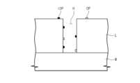
図1は、処理工程が一部遂行された基板の姿を見せてくれる図面である。図1を参照すれば、処理工程が一部遂行された基板(W)上には膜(L)が形成され、蝕刻などの処理を通じて膜(L)を貫通するホール(H、またはパターンとも称する)が形成されることがある。膜(L)は窒化物(Nitride)、酸化物(Oxide)、または金属(例えば、タングステン)のような素材でなされることがある。 FIG. 1 is a diagram showing a substrate after a part of the treatment process has been performed. Referring to FIG. 1, a film (L) is formed on a substrate (W) partially processed, and holes (H or patterns) are formed through the film (L) through processes such as etching. ) may be formed. The film (L) may be made of a material such as Nitride, Oxide, or metal (eg, tungsten).
基板(W)を処理する過程で、基板(W)上には多様な不純物が付着されることがある。例えば、不純物はカーボンを含む有機(Organic)不純物(OP)であることがあって、カーボンを含まない無機(In-Organic)不純物(IOP)であることがある。基板(W)上には有機不純物(OP)、無機不純物(IOP)がすべて付着されていることもあって、場合によっては有機不純物(OP)が付着されていることもある。また、このような不純物らは基板(W)上に形成されているホール(H)内に付着されていることもある。 Various impurities may adhere to the substrate (W) during the process of processing the substrate (W). For example, the impurities may be carbon-containing Organic Impurities (OPs) and may be carbon-free In-Organic Impurities (IOPs). Both organic impurities (OP) and inorganic impurities (IOP) may adhere to the substrate (W), and in some cases organic impurities (OP) may adhere. Also, such impurities may adhere to holes (H) formed on the substrate (W).
一般に、このようなホール(H)に付着された不純物らを除去するため、基板(W)上に薬液を供給する。しかし、最近基板(W)上に形成されるパターンの稠密化、ホール(H)のアスペクト比(Aspect Ratio、AR)が高くなることによって、ホール(H)内に薬液が適切に浸透することができなくて基板(W)上に付着された不純物らが適切に除去されることができないことがある。 In general, a chemical solution is supplied onto the substrate (W) to remove impurities attached to the holes (H). Recently, however, the pattern formed on the substrate (W) has become denser and the aspect ratio (Aspect Ratio, AR) of the holes (H) has increased. Impurities attached to the substrate (W) may not be properly removed.
本発明は、基板を効率的に処理することができる基板処理装置を提供することを一目的とする。 An object of the present invention is to provide a substrate processing apparatus capable of processing substrates efficiently.
また、本発明は基板上に付着された不純物を効果的に除去することができる基板処理装置を提供することを一目的とする。 Another object of the present invention is to provide a substrate processing apparatus capable of effectively removing impurities adhered to a substrate.
また、本発明は基板上に付着された不純物の種類によって処理モードを異にして基板上に付着された不純物の除去効率を改善することができる基板処理装置を提供することを一目的とする。 Another object of the present invention is to provide a substrate processing apparatus capable of improving the removal efficiency of impurities deposited on a substrate by changing the processing mode according to the type of impurities deposited on the substrate.
本発明の目的はこれに制限されないし、言及されなかったまた他の目的らは下の記載らから通常の技術者が明確に理解されることができるであろう。 The objects of the present invention are not limited thereto, and other objects not mentioned will be clearly understood by those of ordinary skill in the art from the following description.
本発明は基板処理装置を提供する。基板処理装置は、処理空間を定義するハウジングと、前記処理空間で基板を支持するチャック-前記チャックには前記処理空間でプラズマを発生させる下部電極が提供される-、上部電極と、及び前記上部電極と前記処理空間との間に配置されるイオンブロッカーを含むことができる。 The present invention provides a substrate processing apparatus. A substrate processing apparatus includes a housing defining a processing space, a chuck supporting a substrate in the processing space, the chuck being provided with a lower electrode for generating plasma in the processing space, an upper electrode, and the upper portion. An ion blocker may be included positioned between the electrode and the processing space.
一実施例によれば、前記イオンブロッカーは接地されて前記上部電極と前記イオンブロッカーとの間空間であるプラズマ空間で発生されたプラズマからイオンを除去することができる。 According to one embodiment, the ion blocker may be grounded to remove ions from a plasma generated in a plasma space between the upper electrode and the ion blocker.
一実施例によれば、前記下部電極に電力を印加する下部電源モジュールと、前記上部電極に電力を印加する上部電源モジュールと、及び前記下部電極または前記上部電極によってプラズマで励起される工程ガスを供給するガス供給ユニットをさらに含むことができる。 According to one embodiment, a lower power module applying power to the lower electrode, an upper power module applying power to the upper electrode, and a process gas excited by plasma by the lower electrode or the upper electrode are connected. It can further include a gas supply unit for supplying.
一実施例によれば、前記ガス供給ユニットは、前記処理空間に工程ガスを供給する第1ガス供給ユニットと、及び前記イオンブロッカーと前記上部電極との間空間であるプラズマ空間に工程ガスを供給する第2ガス供給ユニットと、を含むことができる。 According to one embodiment, the gas supply unit includes a first gas supply unit supplying process gas to the processing space and a plasma space between the ion blocker and the upper electrode. and a second gas supply unit for.
一実施例によれば、前記イオンブロッカーと前記処理空間との間に配置される、シャワーヘッドをさらに含むことができる。 According to one embodiment, a showerhead may be further included between the ion blocker and the processing space.
一実施例によれば、前記第1ガス供給ユニットは、前記シャワーヘッドと前記イオンブロッカーとの間空間であるミキシング空間に工程ガスを供給することができる。 According to one embodiment, the first gas supply unit may supply process gas to a mixing space between the showerhead and the ion blocker.
一実施例によれば、前記第1ガス供給ユニットは、前記イオンブロッカーに形成されたガス供給口と連結される第1ガスラインと、及び前記シャワーヘッドに形成されたガス注入口と連結される第2ガスラインと、を含むことができる。 According to one embodiment, the first gas supply unit is connected to a first gas line connected to a gas supply port formed in the ion blocker and a gas inlet formed in the showerhead. and a second gas line.
一実施例によれば、前記ガス供給口、そして前記ガス注入口は、前記ミキシング空間を向けて工程ガスを供給するように構成されることができる。 According to one embodiment, the gas supply port and the gas inlet may be configured to supply process gas toward the mixing space.
一実施例によれば、前記ガス供給口、そして前記ガス注入口は、前記ミキシング空間のお互いに相異な領域に工程ガスを供給するように構成されることができる。 According to one embodiment, the gas supply port and the gas inlet may be configured to supply process gases to different regions of the mixing space.
一実施例によれば、前記ガス供給口は、前記ミキシング空間の中央領域に工程ガスを供給するように構成され、前記ガス注入口は、前記ミキシング空間の縁領域に工程ガスを供給するように構成されることができる。 According to one embodiment, the gas inlet is configured to supply a process gas to a central region of the mixing space and the gas inlet is configured to supply a process gas to an edge region of the mixing space. can be configured.
一実施例によれば、前記ガス注入口は、前記ミキシング空間には通じるが、前記処理空間には通じないように構成されることができる。 According to one embodiment, the gas inlet may be configured to lead to the mixing space but not to the processing space.
一実施例によれば、前記ガス供給口は、前記ミキシング空間には通じるが、前記プラズマ空間には通じないように構成されることができる。 According to one embodiment, the gas inlet may be configured to lead to the mixing space but not to the plasma space.
一実施例によれば、制御機をさらに含み、前記制御機は、第1モード、第2モード、そして第3モードのうちで何れか一つのモードで基板を処理するように前記下部電源モジュール、前記上部電源モジュール、そして前記ガス供給ユニットを制御し、前記第1モードは、前記プラズマ空間でプラズマを発生させるモードであり、前記第2モードは、前記プラズマ空間と前記処理空間でプラズマを発生させるモードであり、前記第3モードは、前記処理空間でプラズマを発生させるモードであることができる。 According to one embodiment, the lower power supply module further comprises a controller, wherein the controller processes the substrate in one of a first mode, a second mode and a third mode; The upper power supply module and the gas supply unit are controlled, the first mode is a mode for generating plasma in the plasma space, and the second mode is for generating plasma in the plasma space and the processing space. mode, and the third mode may be a mode for generating plasma in the processing space.
また、本発明は基板処理装置を提供する。基板処理装置は、処理空間を定義するハウジングと、前記処理空間で基板を支持する静電チャックと、前記処理空間でプラズマを発生させる下部電極と、前記ハウジングより上部に配置されるイオンブロッカーと、前記イオンブロッカーと対向されるように配置される上部電極-前記上部電極は前記イオンブロッカーと前記上部電極との間空間であるプラズマ空間でプラズマを発生させ、前記プラズマ空間は前記処理空間と流体連通される-と、前記下部電極または前記上部電極によってプラズマ状態で励起される工程ガスを供給するガス供給ユニットと、前記下部電極に電力を印加する下部電源モジュールと、及び前記上部電極に電力を印加する上部電源モジュールと、を含むことができる。 The present invention also provides a substrate processing apparatus. A substrate processing apparatus includes a housing defining a processing space, an electrostatic chuck supporting a substrate in the processing space, a lower electrode generating plasma in the processing space, an ion blocker disposed above the housing, an upper electrode positioned opposite said ion blocker - said upper electrode generating a plasma in a plasma space that is a space between said ion blocker and said upper electrode, said plasma space being in fluid communication with said processing space; Then, a gas supply unit for supplying a process gas excited in a plasma state by the lower electrode or the upper electrode, a lower power supply module for applying power to the lower electrode, and applying power to the upper electrode. and a top power supply module.
一実施例によれば、制御機をさらに含み、前記制御機は、第1モード、第2モード、そして第3モードのうちで何れか一つのモードで基板を処理するように前記下部電源モジュール、前記上部電源モジュール、そして前記ガス供給ユニットを制御し、前記第1モードは、前記プラズマ空間でプラズマを発生させるモードであり、前記第2モードは、前記プラズマ空間と前記処理空間でプラズマを発生させるモードであり、前記第3モードは、前記処理空間でプラズマを発生させるモードであることができる。 According to one embodiment, the lower power supply module further comprises a controller, wherein the controller processes the substrate in one of a first mode, a second mode and a third mode; The upper power supply module and the gas supply unit are controlled, the first mode is a mode for generating plasma in the plasma space, and the second mode is for generating plasma in the plasma space and the processing space. mode, and the third mode may be a mode for generating plasma in the processing space.
一実施例によれば、前記制御機は、前記第1モードで基板を処理時前記ガス供給ユニットがO、H2、NF3、He、Ar、NH3のうちで少なくとも一つ以上の工程ガスを供給するように前記ガス供給ユニットを制御することができる。According to one embodiment, the controller controls the gas supply unit to supply atleastone process gas selected from O, H2, NF3, He, Ar, andNH3 when processing the substrate in the first mode. The gas supply unit can be controlled to supply the
一実施例によれば、前記制御機は、前記第2モードで基板を処理時前記ガス供給ユニットがAr、Xe、NH3、H2、N2、O、NF3、F2、Heのうちで少なくとも一つ以上の工程ガスを供給するように前記ガス供給ユニットを制御することができる。According to one embodiment, the controller controls the gas supply unit to useone of Ar, Xe,NH3 , H2,N2 , O, NF3, F2, and He when processing the substrate in thesecond mode. The gas supply unit can be controlled to supply at least one or more process gases at .
一実施例によれば、前記制御機は、前記第3モードで基板を処理時前記ガス供給He、Ar、Xe、NH3、H2、N2、O、NF3、F2のうちで少なくとも一つ以上の工程ガスを供給するように前記ガス供給ユニットを制御することができる。According to one embodiment, the controller supplies atleast one of the gases He, Ar, Xe,NH3 , H2,N2 , O, NF3, and F2 when processing the substrate in thethird mode. The gas supply unit can be controlled to supply one or more process gases.
また、本発明はパターンが形成された基板を処理する装置において、処理空間を定義するハウジングと、前記処理空間で基板を支持する静電チャック-前記静電チャックには前記処理空間でプラズマを発生させる下部電極が提供される-、前記ハウジングより上部に配置され、前記処理空間を定義するシャワーヘッドと、前記シャワーヘッドより上部に配置され、前記シャワーヘッドと共にミキシング空間を定義するイオンブロッカーと、前記イオンブロッカーより上部に配置され、前記イオンブロッカーと共にプラズマ空間を定義する上部電極-前記上部電極は前記プラズマ空間でプラズマを発生させ-、前記ミキシング空間で工程ガスを供給する第1ガス供給ユニットと、及び前記プラズマ空間に工程ガスを供給する第2ガス供給ユニットと、を含むことができる。 The present invention also provides an apparatus for processing a substrate on which a pattern is formed, comprising: a housing defining a processing space; an electrostatic chuck supporting the substrate in the processing space; and the electrostatic chuck generating plasma in the processing space. a showerhead positioned above the housing and defining the processing space; an ion blocker positioned above the showerhead and defining a mixing space with the showerhead; a first gas supply unit positioned above the ion blocker and defining a plasma space with the ion blocker, the upper electrode generating a plasma in the plasma space, and supplying a process gas in the mixing space; and a second gas supply unit for supplying a process gas to the plasma space.
一実施例によれば、前記下部電極に電力を印加する下部電源モジュールと、前記上部電極に電力を印加する上部電源モジュールと、及び制御機をさらに含み、前記制御機は、基板上に残留する不純物の種類によって第1モード、第2モード、そして第3モードのうちで何れか一つのモードで基板を処理するように前記下部電源モジュール、前記上部電源モジュール、前記第1ガス供給ユニット、そして第2ガス供給ユニットを制御し、前記第1モードは、前記プラズマ空間でプラズマを発生させるモードであり、前記第2モードは、前記プラズマ空間と前記処理空間でプラズマを発生させるモードであり、前記第3モードは、前記処理空間でプラズマを発生させるモードであることができる。 According to one embodiment, it further includes a lower power module applying power to the lower electrode, an upper power module applying power to the upper electrode, and a controller, wherein the controller remains on the substrate. The lower power module, the upper power module, the first gas supply unit, and the first gas supply unit are arranged to process the substrate in one of a first mode, a second mode, and a third mode according to the type of impurities. The first mode is a mode for generating plasma in the plasma space, the second mode is a mode for generating plasma in the plasma space and the processing space, and the second mode is a mode for generating plasma in the plasma space and the processing space. The three modes may be modes for generating plasma in the processing space.
本発明の一実施例によれば、基板を効率的に処理することができる。 According to one embodiment of the present invention, substrates can be efficiently processed.
また、本発明の一実施例によれば、基板上に付着された不純物を効果的に除去することができる。 Also, according to an embodiment of the present invention, impurities adhered to the substrate can be effectively removed.
また、本発明の一実施例によれば、基板上に付着された不純物の種類によって処理モードを異にして基板上に付着された不純物の除去効率を改善することができる。 Also, according to an embodiment of the present invention, it is possible to improve the efficiency of removing impurities attached to the substrate by using different treatment modes according to the types of impurities attached to the substrate.
本発明の効果が上述した効果らに限定されるものではなくて、言及されない効果らは本明細書及び添付された図面らから本発明が属する技術分野で通常の知識を有した者に明確に理解されることができるであろう。 The effects of the present invention are not limited to the effects described above, and the effects not mentioned will be apparent to those skilled in the art from the present specification and the accompanying drawings. can be understood.
以下では添付した図面を参照にして本発明の実施例に対して本発明が属する技術分野で通常の知識を有した者が容易に実施できるように詳しく説明する。しかし、本発明はいろいろ相異な形態で具現されることができるし、ここで説明する実施例で限定されない。また、本発明の望ましい実施例を詳細に説明するにおいて、関連される公知機能または構成に対する具体的な説明が本発明の要旨を不必要に曇ることがあると判断される場合にはその詳細な説明を略する。また、類似機能及び作用をする部分に対しては図面全体にかけて等しい符号を使用する。 Hereinafter, embodiments of the present invention will be described in detail with reference to the accompanying drawings so that those skilled in the art can easily implement the present invention. The present invention may, however, be embodied in many different forms and should not be construed as limited to the embodiments set forth herein. Also, in describing the preferred embodiments of the present invention in detail, if it is determined that the specific description of related well-known functions or configurations may unnecessarily obscure the gist of the present invention, the detailed description thereof will be omitted. Omit description. Also, the same reference numerals are used throughout the drawings for parts having similar functions and actions.
ある構成要素を‘包含'するということは、特別に反対される記載がない限り他の構成要素を除くことではなく、他の構成要素をさらに含むことができるということを意味する。具体的に,“含む”または“有する”などの用語は明細書上に記載した特徴、数字、段階、動作、構成要素、部品またはこれらを組み合わせたものが存在することを指定しようとすることであって、一つまたはその以上の他の特徴らや数字、段階、動作、構成要素、部品またはこれらを組み合わせたものなどの存在または付加可能性をあらかじめ排除しないものとして理解されなければならない。 'Including' a component means that it can further include other components, not excluding other components, unless specifically stated to the contrary. Specifically, terms such as "including" or "having" are intended to indicate the presence of the features, numbers, steps, acts, components, parts, or combinations thereof set forth in the specification. and does not preclude the presence or addition of one or more other features, figures, steps, acts, components, parts or combinations thereof.
単数の表現は文脈上明白に異なるように志さない限り、複数表現を含む。また、図面で要素らの形状及び大きさなどはより明確な説明のために誇張されることがある。 Singular expressions include plural expressions unless the context clearly dictates otherwise. Also, the shapes and sizes of elements in the drawings may be exaggerated for clearer description.
第1、第2などの用語は多様な構成要素らを説明することに使用されることができるが、前記構成要素らは前記用語によって限定されてはいけない。前記用語は一つの構成要素を他の構成要素から区別する目的で使用されることができる。例えば、本発明の権利範囲から離脱されないまま第1構成要素は第2構成要素で命名されることができるし、類似第2構成要素も第1構成要素に命名されることができる。 Although the terms first, second, etc. may be used to describe various components, the components should not be limited by the terms. The terms may be used to distinguish one component from another component. For example, a first component could be named a second component, and a similar second component could also be named a first component without departing from the scope of the present invention.
ある構成要素が異なる構成要素に“連結されて”いるか、または“接続されて”いると言及された時には、その他の構成要素に直接的に連結されているか、または接続されていることもあるが、中間に他の構成要素が存在することもあると理解されなければならないであろう。反面に、ある構成要素が異なる構成要素に“直接連結されて”いるか、または“直接接続されて”いると言及された時には、中間に他の構成要素が存在しないことで理解されなければならないであろう。構成要素らとの関係を説明する他の表現ら、すなわち“~間に”と“すぐ~間に”または“~に隣合う”と“~に直接隣合う”なども同じく解釈されなければならない。 When one component is referred to as being “coupled” or “connected” to another component, it may be directly coupled or connected to the other component. , it should be understood that there may be other components in between. Conversely, when one component is referred to as being “directly coupled” or “directly connected” to another component, it should be understood that there are no other components in between. be. Other expressions describing relationships to components, namely "between" and "immediately between" or "adjacent to" and "directly adjacent to", etc., should be interpreted in the same way. .
異なるように定義されない限り、技術的であるか科学的な用語を含んでここで使用されるすべての用語らは、本発明が属する技術分野で通常の知識を有した者によって一般的に理解されることと等しい意味である。一般に使用される前もって定義されているもののような用語は、関連技術の文脈上有する意味と一致する意味であることで解釈されなければならないし、本出願で明白に定義しない限り、理想的や過度に形式的な意味で解釈されない。 Unless defined otherwise, all terms, including technical or scientific terms, used herein are commonly understood by one of ordinary skill in the art to which this invention belongs. is equivalent to Terms such as pre-defined in common usage should be construed to mean in a manner consistent with the meaning they have in the context of the relevant art, and unless expressly defined in this application, do not mean ideal or excessive. not interpreted in a formal sense.
以下では、図2乃至図10を参照して本発明の実施例に対して説明する。 Hereinafter, embodiments of the present invention will be described with reference to FIGS. 2 to 10. FIG.
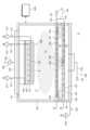
図2は、本発明の一実施例による基板処理装置を見せてくれる図面である。図2を参照すれば、本発明の一実施例による基板処理装置10は基板(W)を処理することができる。基板処理装置10はプラズマを利用して基板(W)を処理することができる。基板処理装置10はプラズマを利用して基板(W)上に付着された不純物を除去することができる。基板処理装置10に搬入される基板(W)は処理工程が一部遂行された基板(W)が搬入されることができる。例えば、基板処理装置10に搬入される基板(W)は、蝕刻工程、写真工程などが遂行された基板(W)が搬入されることがある。例えば、基板処理装置10に搬入された処理対象である基板(W)は、前で図1を参照して説明した基板(W)と同一または類似な状態(すなわち、有機不純物(OP)と無機不純物(IOP)がすべて付着された状態で基板処理装置10に搬入されることができる。これと異なり、基板(W)上に有機不純物(OP)だけが付着された状態で基板処理装置10に搬入されることもできる。 FIG. 2 is a diagram showing a substrate processing apparatus according to an embodiment of the present invention. Referring to FIG. 2, a
基板処理装置10は、ハウジング100、チャック200、シャワーヘッド300、加熱部材400、イオンブロッカー500、絶縁部材(DR)、上部電極(第2電極の一例)600、ガス供給ユニット700、800、排気ユニット900、そして制御機1000を含むことができる。 The
ハウジング100とシャワーヘッド300はお互いに組合され、基板(W)が処理される空間である処理空間(A1、第1空間の一例)を定義することができる。また、シャワーヘッド300、加熱部材400、そして、イオンブロッカー500はお互いに組合されてイオン(I)が除去されたプラズマ(P)と第1ガス供給ユニット700が供給する第1工程ガス(G1)をお互いにミキシングする空間であるミキシング空間(A3、第3空間の一例)を定義することができる。また、イオンブロッカー500、絶縁部材(DR)、上部電極600はお互いに組合され、プラズマ(P)が発生される空間であるプラズマ空間(A2、第2空間の一例)を定義することができる。また、処理空間(A1)、プラズマ空間(A2)、そしてミキシング空間(A3)を定義することに関与する構成らを通称してチャンバと呼ぶこともある。 The
ハウジング100は処理空間(A1)を定義することができる。例えば、ハウジング100は後述するシャワーヘッド300とお互いに組合されて処理空間(A1)を定義することができる。ハウジング100は上部が開放された桶形状を有することができる。ハウジング100の内側壁は、後述するプラズマ(P)によって蝕刻されることを防止することができる素材でコーティングされることができる。例えば、ハウジング100の内側壁はセラミックスのような誘電体膜でコーティングされることができる。また、ハウジング100は接地されることができる。また、ハウジング100には基板(W)が処理空間(A1)に搬入されるか、または処理空間(A1)から搬出されることができるように開口(図示せず)が形成されることがある。開口はドア(図示せず)によって選択的に遮蔽されることができる。
チャック200は処理空間(A1)で基板(W)を支持することができる。チャック200は基板(W)を加熱することができる。また、チャック200は基板(W)を静電気力を利用してチャッキング(Chucking)することができるESCであることがある。チャック200は支持板210、静電電極220、ヒーター230、そして下部電極(第1電極の一例)240を含むことができる。 The
支持板210は基板(W)を支持することができる。支持板210は基板(W)を支持する支持面を有することができる。支持板210は誘電体で提供されることができる。例えば、支持板210はセラミックス素材で提供されることができる。支持板210内には静電電極220が提供されることができる。静電電極220は上部から眺める時、基板(W)と重畳される位置に提供されることができる。静電電極220に電力が印加されれば、静電電極220は基板(W)をチャッキングさせることができる静電気力による電界を形成することができる。電界は基板(W)が支持板210を向ける方向にチャックキングされるようにする人力を基板(W)に伝達することができる。また、電界は、後述するイオン(I)が基板(W)を向けて直進で流動(すなわち、イオン(I)が異方性を有するように)するようにできる。 The
また、基板処理装置10、例えばチャック200は静電電極220に電力を印加する第1電源モジュール222、224を含むことができる。第1電源モジュール222、224は静電電極電源222及び静電電極スイッチ224を含むことができる。静電電極スイッチ224のオン/オフによって静電電極220には電力が印加されることができる。 The
ヒーター230は基板(W)を加熱することができる。ヒーター230は支持板210の温度を上昇させて基板(W)を加熱することができる。また、ヒーター230に電力が印加されればヒーター230は熱を発生させることができる。ヒーター230はタングステンのような発熱体であることがある。しかし、ヒーター230の種類はこれに限定されるものではなくて、公知されたヒーター230で多様に変形されることができる。ヒーター230は基板(W)が処理されるうちに基板(W)から分離される不純物(例えば、Si-ポリマー)がホール(H)に再付着されることを防止できるように、支持板210の温度を高めることができる。例えば、ヒーター230は支持板210の温度を85℃乃至130℃で制御することができる。 The
また、基板処理装置10、例えばチャック200はヒーター230に電力を印加する第2電源モジュール232、234を含むことができる。第2電源モジュール232、234はヒーター電源232及びヒーター電源スイッチ234を含むことができる。ヒーター電源スイッチ234のオン/オフによってヒーター230には電力が印加されることができる。 Also, the
下部電極240は処理空間(A1)でプラズマを発生させることができる。下部電極240は板形状を有することができる。下部電極240は後述するシャワーヘッド300とお互いに対向される電極であることができる。下部電極240に電力が印加されれば、下部電極240は処理空間(A1)に電界を形成し、形成された電界は処理空間(A1)に流入(供給)される工程ガス(G1、G2)を励起させてプラズマ(P)を発生させることができる。また、基板処理装置10、例えばチャック200は下部電極240に電力を印加する下部電源モジュール242、244を含むことができる。下部電源モジュール242、244はRFソースである下部電源242及び下部電源スイッチ244を含むことができる。下部電源スイッチ244のオン/オフによって下部電極240には電力が印加されることができる。 The
シャワーヘッド300はハウジング100の上部に配置されることができる。シャワーヘッド300は後述するイオンブロッカー500と処理空間(A1)との間に配置されることができる。シャワーヘッド300は接地されることができる。シャワーヘッド300は接地されて上述した下部電極240とお互いに対向電極で機能することができる。また、シャワーヘッド300には複数のホール302が形成されることができる。ホール302はシャワーヘッド300の上面から下面まで延長されて形成されることができる。すなわち、ホール302はシャワーヘッド300を貫通して形成されることができる。ホール302は処理空間(A1)と後述するプラズマ空間(A2)をお互いに流体連通させることができる。また、ホール302は処理空間(A1)と後述するミキシング空間(A3)をお互いに流体連通させることができる。 A
また、シャワーヘッド300にはガス注入口304が形成されることができる。ガス注入口304は後述する第2ガスライン706と連結されることができる。ガス注入口304はミキシング空間(A3)を向けて第1工程ガス(G1)を供給するように構成されることができる。ガス注入口304はミキシング空間(A3)の縁領域に工程ガスを供給するように構成されることができる。ガス注入口304はミキシング空間(A3)には通じるが(また、間接的にプラズマ空間(A2)と通じるが)、処理空間(A1)には通じないように構成されることができる。 Also, a
加熱部材400はシャワーヘッド300の上部に配置されることができる。加熱部材400は上部から眺める時リング形状を有するリングヒーターであることができる。加熱部材400は熱を発生させてミキシング空間(A3)の温度を高めてイオン(I)が除去されたプラズマ(P)と第1工程ガス(G1)がミキシングされることがより効果的になされることができるように助けることができる。 The
イオンブロッカー500はプラズマ空間(A2)とミキシング空間(A3)を区画(さらに延いてはプラズマ空間(A2)と処理空間(A1)を間接的に区画)することができる。イオンブロッカー500は上部電極600と処理空間(A1)との間に配置されることができる。 The
イオンブロッカー500は加熱部材400の上部に配置されることができる。イオンブロッカー500は接地されることができる。イオンブロッカー500は接地され、プラズマ空間(A2)で発生されたプラズマ(P)がミキシング空間(A3)、さらに延いては処理空間(A1)に流入時、プラズマ(P)が含むイオン(I)を除去することができる。要するに、プラズマ空間(A2)で発生されたプラズマ(P)は、イオンブロッカー500を経りながらイオン(I)が除去されるので、実質的にラジカル(R)のみを含むようになることができる。 The
また、イオンブロッカー500は接地されて後述する上部電極600とお互いに対向電極として機能することができる。イオンブロッカー500には複数の通孔502らが形成されることができる。通孔502らはイオンブロッカー500を貫通して形成されることができる。通孔502らはプラズマ空間(A2)とミキシング空間(A3)を流体連通させることができる。通孔502らはプラズマ空間(A2)と処理空間(A1)を流体連通させることができる。 In addition, the
また、イオンブロッカー500にはガス供給口504が形成されることがある。ガス供給口504は後述する第1ガスライン704と連結されることができる。ガス供給口504はミキシング空間(A3)工程ガスを供給するように構成されることができる。ガス供給口504はミキシング空間(A3)の中央領域に工程ガスを供給するように構成されることができる。ガス供給口504はミキシング空間(A3)には通じるが(また、間接的に処理空間(A1)と通じるが)、プラズマ空間(A2)には通じないように構成されることができる。 Also, the
上部電極600は板形状を有することができる。上部電極600はプラズマを発生させることができる。上部電極600には、基板処理装置10が有する上部電源モジュール602、604が電力を印加することができる。上部電源モジュール602、604はRFソースである上部電源602及び下部電源スイッチ604を含むことができる。上部電源スイッチ602のオン/オフによって上部電極600には電力が印加されることができる。上部電極600に電力が印加されれば、対向電極として機能するイオンブロッカー500と上部電極600との間に電界が形成され、これにプラズマ空間(A2)で後述する第2工程ガス(G2)を励起してプラズマを発生させることができる。また、上部電極600とイオンブロッカー500との間には絶縁素材で提供される絶縁部材(DR)が配置されることができる。絶縁部材(DR)は上部から眺める時、リング形状を有することができる。 The
ガス供給ユニット700、800はプラズマ(P)状態で励起される工程ガス(G1、G2)を供給することができる。ガス供給ユニット700、800は第1ガス供給ユニット700、そして、第2ガス供給ユニット800を含むことができる。以下では、第1ガス供給ユニット700が供給する工程ガスを、第1工程ガス(G1)と言って、第2ガス供給ユニット800が供給する工程ガスを、第2工程ガス(G2)と言う。 The
第1ガス供給ユニット700はミキシング空間(A3)に工程ガスを供給することができる。第1ガス供給ユニット700はミキシング空間(A3)に工程ガスを注入し、処理空間(A1)に工程ガスを供給することができる。第1ガス供給ユニット700は第1ガス供給源701、メインガスライン703、第1ガスライン704及び第2ガスライン706を含むことができる。メインガスライン703の一端は第1ガス供給源701と連結されることができるし、メインガスライン703の他端は第1ガスライン704及び第2ガスライン706に分岐されることができる。第1ガスライン704は上述したガス供給口504と連結されることができる。また、第2ガスライン706は上述したガス注入口304と連結されることができる。 The first
第1ガス供給ユニット700が供給する第1工程ガス(G1)はHe、Ar、Xe、NH3、H2、N2、O、NF3、F2のうちで少なくとも一つ以上であることがある。The first process gas (G1) supplied by the first
第2ガス供給ユニット800はプラズマ空間(A2)に工程ガスを供給することができる。第2ガス供給ユニット800はプラズマ空間(A2)に工程ガスを注入し、ミキシング空間(A2)、そして、処理空間(A1)に工程ガスを供給することができる。第2ガス供給ユニット800は第2ガス供給源801、そして、ガスチャンネル803を含むことができる。ガスチャンネル803の一端は第2ガス供給源801と連結され、他端はプラズマ空間(A2)と連通されることができる。 The second
第2ガス供給ユニット800が供給する第2工程ガス(G2)はNF3、F2、He、Ar、Xe、H2、N2のうちで少なくとも一つ以上であることがある。The second process gas (G2) supplied by thesecond
排気ユニット900は処理空間(A1)に供給された工程ガス(G1、G2)、工程副産物などを排出することができる。排気ユニット900は処理空間(A1)の圧力を調節することができる。排気ユニット900は減圧部材902、そして、減圧ライン904を含むことができる。減圧部材902はポンプであることができる。しかし、これに限定されるものではなくて、減圧を提供する公知された装置で多様に変形されることができる。 The
制御機1000は基板処理装置10、具体的に基板処理装置10が有する構成らを制御することができる。例えば、制御機10はガス供給ユニット700、800、第1電源モジュール222、224、第2電源モジュール232、234、減圧部材902、下部電源モジュール242、244、上部電源モジュール602、604などを制御することができる。制御機1000は基板処理装置10の制御を行うマイクロプロセッサー(コンピューター)でなされるプロセスコントローラーと、オペレーターが基板処理装置を管理するためにコマンド入力操作などを行うキーボードや、基板処理装置の稼働状況を可視化して表示するディスプレイなどでなされるユーザーインターフェースと、基板処理装置10で実行される処理をプロセスコントローラーの制御で実行するための制御プログラムや、各種データ及び処理条件によって各構成部に処理を実行させるためのプログラム、すなわち、処理レシピが記憶された記憶部を具備することができる。また、ユーザーインターフェース及び記憶部はプロセスコントローラーに接続されることがある。処理レシピは記憶部のうちで記憶媒体に記憶されることがあって、記憶媒体は、ハードディスクであっても良く、CD-ROM、DVDなどの可搬性ディスクや、フラッシュメモリーなどの半導体メモリーであることもある。 The
以下では、本発明の一実施例による基板処理方法に対して説明する。以下で説明する基板処理方法は、前述した基板処理装置10によって遂行されることがある。また、以下で説明する基板処理方法を遂行するために制御機1000は基板処理装置10が有する構成らを制御することができる。 Hereinafter, a substrate processing method according to an embodiment of the present invention will be described. The substrate processing method described below may be performed by the
以下では、第1ガス供給ユニット700が供給する工程ガスを第1工程ガス(G1)と言って、第2ガス供給ユニット800が供給する工程ガスを第2工程ガス(G2)と言う。また、処理空間(A1)で工程ガスが励起されて発生されるプラズマを第1プラズマ(P1)と言って、プラズマ空間(A2)で工程ガスが励起されて発生するプラズマを第2プラズマ(P2)と言う。プラズマ空間(A2)で発生される第2プラズマ(P2)が処理空間(A1)に流入される場合、イオンブロッカー500によってイオンが除去されるので、第2プラズマ(P2)はイオンが除去されたプラズマを意味することができる。また、処理空間(A1)で発生する第1プラズマ(P1)はイオンブロッカー500によってイオンが除去されないので、第1プラズマ(P1)はイオンを含むプラズマを意味することができる。 Hereinafter, the process gas supplied by the first
図3は、図2の基板処理装置が基板を処理時選択することができる処理モードの姿を図式化した図面である。図3を参照すれば、制御機1000は先行工程(PT)の種類によって、基板処理装置10の処理モードを選択することができる。例えば、制御機1000は先行工程(PT)の種類によって、第1モード(M1)、第2モード(M2)、そして、第3モード(M3)のうちで何れか一つのモードを選択して基板処理装置10が基板(W)を処理するように基板処理装置10の下部電源モジュール242、244、上部電源モジュール602、604、そして、ガス供給ユニット700、800を制御することができる。 FIG. 3 is a diagram illustrating processing modes that the substrate processing apparatus of FIG. 2 can select when processing a substrate. Referring to FIG. 3, the
例えば、先行工程(PT)が基板(W)を蝕刻する蝕刻工程である場合、基板(W)上には有機不純物(OP)と無機不純物(IOP)すべてが付着されることがある。これに、先行工程(PT)が蝕刻工程である場合には、後述する第1モード(M1)または第2モード(M2)で基板処理装置10が基板(W)を処理することができる。 For example, if the preceding process (PT) is an etching process for etching the substrate (W), both organic impurities (OP) and inorganic impurities (IOP) may adhere to the substrate (W). In addition, when the preceding process (PT) is an etching process, the
これと異なり、先行工程(PT)が感光液及び現像液を供給して基板(W)を処理する写真工程である場合、基板(W)上には有機不純物(OP)が付着されることがある。これに、先行工程(PT)が写真工程である場合、後述する第3モード(M3)で基板処理装置10が基板(W)を処理することができる。 In contrast, when the preceding process (PT) is a photographic process in which the substrate (W) is processed by supplying a photosensitive solution and a developer, organic impurities (OP) may adhere to the substrate (W). be. In addition, when the preceding process (PT) is a photo process, the
第1モード(M1)はプラズマ空間(A2)でプラズマを発生させ、イオンが除去されたプラズマを基板(W)に伝達して基板(W)を処理する工程(すなわち、ラジカルを利用して基板(W)を処理する工程)である第1ラジカル工程(M11)、そして、第2ラジカル工程(M12が遂行されるモードであることができる。第1ラジカル工程(M11)、そして、第2ラジカル工程(M12)は交番及び繰り返して遂行されることができる。第1モード(M1)は有機不純物及び無機不純物をすべて除去することができるモードであることができる。 In the first mode (M1), plasma is generated in the plasma space (A2), and the plasma from which ions are removed is transferred to the substrate (W) to process the substrate (W) (that is, the substrate (W) is treated using radicals). The first radical step (M11), which is the step of treating (W), and the second radical step (M12) can be performed. The first radical step (M11) and the second radical The step (M12) may be alternately and repeatedly performed, and the first mode (M1) may be a mode capable of removing all organic and inorganic impurities.
第2モード(M2)は処理空間(A1)でプラズマを発生させ、イオンが含まれたプラズマを基板(W)に伝達して基板(W)を処理する工程であるイオン処理工程(M21)が遂行され、またプラズマ空間(A2)でプラズマを発生させてイオンが除去されたプラズマを基板(W)に伝達して基板(W)を処理する工程(すなわち、ラジカルを利用して基板(W)を処理する工程)であるラジカル処理工程(M22)が遂行されるモードであることができる。イオン処理工程(M21)及びラジカル処理工程(M22)は交番及び繰り返して遂行されることができる。第2モード(M2)は有機不純物及び無機不純物をすべて除去することができるモードであることができる。 The second mode (M2) includes an ion treatment process (M21), which is a process of processing the substrate (W) by generating plasma in the processing space (A1) and transmitting the plasma containing ions to the substrate (W). The process of generating plasma in the plasma space (A2) and transmitting the plasma from which ions are removed to the substrate (W) to process the substrate (W) (that is, the substrate (W) using radicals) can be a mode in which a radical treatment step (M22), which is a step of treating the The ion treatment process (M21) and the radical treatment process (M22) can be performed alternately and repeatedly. A second mode (M2) may be a mode capable of removing both organic and inorganic impurities.
第3モード(M3)は処理空間(A1)でプラズマを発生させ、イオンが含まれたプラズマを基板(W)に伝達して基板(W)を処理する工程であるイオン処理工程のみを遂行することができる。第3モード(M3)有機不純物を除去することができるモードであることができる。 In the third mode (M3), plasma is generated in the processing space (A1) and the plasma including ions is transferred to the substrate (W) to perform only the ion treatment process, which is the process of treating the substrate (W). be able to. A third mode (M3) may be a mode capable of removing organic impurities.
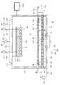
図4は、図3の第1モードの第1ラジカル工程を遂行する基板処理装置の姿を見せてくれる図面である。図4を参照すれば、第1ラジカル工程(M11)時第2ガス供給ユニット800はプラズマ空間(A2)に第2工程ガス(G2)を供給することができる。第2工程ガス(G2)はH2、NH3、NF3、Oのうちで少なくとも一つ以上と、He、Arのうちで少なくとも一つ以上を含むことができる。上部電極600はプラズマ空間(A2)に電界を形成することができる。プラズマ空間(A2)で発生された第2プラズマ(P2)はイオンブロッカー500を経って流れながらイオン(I)が除去され、イオンが除去された第2プラズマ(P2)は処理空間(A1)に流入されて基板(W)に伝達することができる。FIG. 4 is a view showing the appearance of the substrate processing apparatus performing the first radical process of the first mode of FIG. Referring to FIG. 4, the second
第2工程ガス(G2)が水素(H)を含む工程ガスである場合、基板(W)上のカーボン(C)は水素ラジカルと反応し、CH4形態で基板(W)から分離されることができる。第2工程ガス(G2)が酸素(O)を含む工程ガスである場合、基板(W)上のカーボン(C)は水素ラジカルと反応し、CO2形態で基板(W)から分離されることができる。第2工程ガス(G2)が水素(F)を含む工程ガスである場合、基板(W)上のカーボン(C)は水素ラジカルと反応し、CF4形態で基板(W)から分離されることができる。すなわち、第1ラジカル工程(M11)は基板(W)上の有機不純物(OP)を除去することができる。When the second process gas (G2) is a process gas containing hydrogen (H), carbon (C) on the substrate (W) reacts with hydrogen radicals and is separated from the substrate( W) in the form of CH4. can be done. When the second process gas (G2) is a process gas containing oxygen (O), carbon (C) on the substrate (W) reacts with hydrogen radicals and is separated from the substrate (W) in the form ofCO2 . can be done. When the second process gas (G2) is a process gas containing hydrogen (F), carbon (C) on the substrate (W) reacts with hydrogen radicals and is separated from the substrate( W) in the form of CF4. can be done. That is, the first radical process (M11) can remove the organic impurities (OP) on the substrate (W).
図5は、図3の第1モードの第2ラジカル工程を遂行する基板処理装置の姿を見せてくれる図面である。図5を参照すれば、第2ラジカル工程(M12)時第1ガス供給ユニット700はミキシング空間(A3)で第1工程ガス(G1)を供給し、第2ガス供給ユニット800はプラズマ空間(A2)で第2工程ガス(G2)を供給することができる。上部電極600はプラズマ空間(A2)に電界を形成することができる。 FIG. 5 is a diagram showing a substrate processing apparatus performing a second radical process of the first mode of FIG. 3. Referring to FIG. Referring to FIG. 5, during the second radical process (M12), the first
第1工程ガス(G1)はNH3を含むことができる。第2工程ガス(G2)はNF3及びHeとArのうちで少なくとも何れか一つを含むことができる。プラズマ空間(A2)で発生された第2プラズマ(P2)はイオンブロッカー500を経って流れながらイオン(I)が除去され、イオンが除去された第2プラズマ(P2)はミキシング空間(A3)で第1工程ガス(G1)と会って混合されることができる。イオンが除去された第2プラズマ(P2)は第1工程ガス(G1)とミキシングされた状態で処理空間(A1)に流入されることができる。The first process gas (G1) may containNH3 . The second process gas (G2) may include NF3 and atleast one of He and Ar. The second plasma (P2) generated in the plasma space (A2) has ions (I) removed while flowing through the
第2工程ガス(G2)がNF3を含み、第1工程ガス(G1)がNH3を含めば、イオンが除去された第2プラズマ(P2)と第1工程ガス(G1)はお互いに反応してNH4Fを生成することができる。NH4Fが処理空間(A1)に流入されて基板(W)に伝達されれば、基板上に付着された無機不純物(IOP)であるSiO2はNH4Fとお互いに反応して(NH4-)2SiF6形態基板(W)から分離されることができる。If the second process gas (G2) contains NF3 and the first process gas (G1) containsNH3, the ion-removed second plasma (P2) and the first process gas (G1) react with each other. can be used to generate NH4 F. WhenNH4F is introduced into the processing space (A1) and transferred to the substrate (W),SiO2 , which is an inorganic impurity (IOP) deposited on the substrate, reacts withNH4F (NH4- ) can be separated from the2SiF 6form substrate (W).
図6は、図3の第2モードのイオン処理工程を遂行する基板処理装置の姿を見せてくれる図面である。図6を参照すれば、イオン処理工程(M21)時第1ガス供給ユニット700はミキシング空間(A3)で第1工程ガス(G1)を供給することができる。 FIG. 6 is a view showing the appearance of the substrate processing apparatus performing the ion processing process of the second mode of FIG. Referring to FIG. 6, during the ion processing process (M21), the first
第1工程ガス(G1)はHe、Ar、Xeのうちで少なくとも何れか一つ、そして、NH3、H2、N2、O、NF3、F2のうちで少なくとも何れか一つを含むことができる。第1工程ガス(G1)が処理空間(A1)に流入されれば、処理空間(A1)で下部電極240が発生させる電界によって第1工程ガス(G1)は第1プラズマ(P1)に励起されることができる。The first process gas (G1) includes at least one of He, Ar, and Xe, and atleastone ofNH3 , H2,N2 , O, NF3, and F2. be able to. When the first process gas (G1) flows into the processing space (A1), the electric field generated by the
第1工程ガス(G1)はNH3を含むことができる。第2工程ガス(G2)はNF3及びHeとArのうちで少なくとも何れか一つを含むことができる。プラズマ空間(A2)で発生された第2プラズマ(P2)はイオンブロッカー500を経って流れながらイオン(I)が除去され、イオンが除去された第2プラズマ(P2)はミキシング空間(A3)で第1工程ガス(G1)と会って混合されることができる。イオンが除去された第2プラズマ(P2)は第1工程ガス(G1)とミキシングされた状態で処理空間(A1)に流入されることができる。The first process gas (G1) may containNH3 . The second process gas (G2) may include NF3 and atleast one of He and Ar. The second plasma (P2) generated in the plasma space (A2) has ions (I) removed while flowing through the
第2工程ガス(G2)がNF3を含み、第1工程ガス(G1)がNH3を含めば、イオンが除去された第2プラズマ(P2)と第1工程ガス(G1)はお互いに反応してNH4Fを生成することができる。NH4Fが処理空間(A1)に流入されて基板(W)に伝達されれば、基板上に付着された無機不純物(IOP)であるSiO2はNH4Fとお互いに反応して(NH4-)2SiF6形態基板(W)から分離されることができる。If the second process gas (G2) contains NF3 and the first process gas (G1) containsNH3, the ion-removed second plasma (P2) and the first process gas (G1) react with each other. can be used to generate NH4 F. WhenNH4F is introduced into the processing space (A1) and transferred to the substrate (W),SiO2 , which is an inorganic impurity (IOP) deposited on the substrate, reacts withNH4F (NH4- ) can be separated from the2SiF 6form substrate (W).
また、イオン処理工程(M21)が遂行されるうちに、基板(W)は静電電極220によってチャッキングされることができる。静電電極220に電力が印加されれば、基板(W)上には下に向ける方向に引っぱる力を発生させる電界が形成されることができる。このような電界は基板(W)をチャッキング(Chucking)するだけでなく、後述するイオン(I)が異方性の状態(すなわち、イオン(I)が下に向ける方向に垂直するように流動する状態)を有するようにすることもできる。 Also, the substrate (W) can be chucked by the
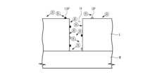
処理空間(A1)で発生される第1プラズマ(P1)はイオンブロッカー500を経らないで、処理空間(A1)で直接的に発生するようになるので、イオン(I)を含むことができる。第1プラズマ(P1)が含むイオン(I)は極性を有するので、静電電極220が形成する静電気力によって異方性を有するようになることができる。これに、図7に示されたようにイオン(I)はホール(H)内に進入して有機不純物(OP)及び/または無機不純物(IOP)に伝達されることができる。 Since the first plasma (P1) generated in the processing space (A1) is directly generated in the processing space (A1) without going through the
不純物らは膜(L)、ホール(H)、基板(W)に対して突き出されているはずであるので、無機不純物(IOP)は膜(L)、ホール(H)、基板(W)に比べて相対的にイオン(I)によって物理的にさらに処理されることができる。すなわち、イオン(I)によって処理された領域と処理されない領域との間に差が選択比の差を発生させることができる。 Impurities should protrude with respect to the film (L), holes (H), and substrate (W), so inorganic impurities (IOPs) are projected into the film (L), holes (H), and substrate (W). can be physically further processed by ions (I) in comparison. That is, the difference between the areas treated with ions (I) and the areas not treated can produce a difference in selectivity.
また、第1工程ガス(G1)が水素(H)を含む工程ガスである場合、基板(W)上のカーボン(C)は水素ラジカルと反応し、CH4形態で基板(W)から分離されることができる。第1工程ガス(G1)が酸素(O)を含む工程ガスである場合、基板(W)上のカーボン(C)は水素ラジカルと反応し、CO2形態で基板(W)から分離されることができる。第1工程ガス(G1)が水素(F)を含む工程ガスである場合、基板(W)上のカーボン(C)は水素ラジカルと反応し、CF4形態で基板(W)から分離されることができる。すなわち、第1ラジカル工程(M11)は基板(W)上の有機不純物(OP)を化学的に除去することができる。In addition, when the first process gas (G1) is a process gas containing hydrogen (H), carbon (C) on the substrate (W) reacts with hydrogen radicals and is separated from the substrate( W) in the form of CH4. can When the first process gas (G1) is a process gas containing oxygen (O), carbon (C) on the substrate (W) reacts with hydrogen radicals and is separated from the substrate (W) in the form ofCO2 . can be done. When the first process gas (G1) is a process gas containing hydrogen (F), carbon (C) on the substrate (W) reacts with hydrogen radicals and is separated from the substrate( W) in the form of CF4. can be done. That is, the first radical process (M11) can chemically remove the organic impurities (OP) on the substrate (W).
図8は、図3の第2モードのラジカル処理工程を遂行する基板処理装置の姿を見せてくれる図面である。 FIG. 8 is a view showing the appearance of a substrate processing apparatus performing the second mode radical treatment process of FIG.
ラジカル処理工程(M22)時第1ガス供給ユニット700はミキシング空間(A3)に第1工程ガス(G1)を供給し、第2ガス供給ユニット800はプラズマ空間(A2)に第2工程ガス(G2)を供給することができる。プラズマ空間(A2)には上部電極600が電界を形成することができる。 During the radical treatment process (M22), the first
第2工程ガス(G2)はNF3、F2のうちで少なくとも何れか一つ、そして、He、Ar、Xe、H2、N2のうちで少なくとも何れか一つを含むことができる。また、第1工程ガス(G1)はNF3、そして、F2のうちで少なくとも何れか一つを含むことができる。Thesecond process gas (G2) may include atleast one of NF3 and F2 and atleast one of He, Ar, Xe, H2 andN2 . Also, the first process gas (G1) may include atleastone of NF3 and F2.
プラズマ空間(A2)で発生された第2プラズマ(P2)はイオンブロッカー500を経って流れながらイオン(I)が除去され、イオンが除去された第2プラズマ(P2)はミキシング空間(A3)で第1工程ガス(G1)と会って混合されることができる。イオンが除去された第2プラズマ(P2)は第1工程ガス(G1)とミキシングされた状態で処理空間(A1)に流入されることができる。 The second plasma (P2) generated in the plasma space (A2) has ions (I) removed while flowing through the
第2工程ガス(G2)がNF3を含み、第1工程ガス(G1)がNH3を含めば、イオンが除去された第2プラズマ(P2)と第1工程ガス(G1)はお互いに反応してNH4Fを生成することができる。NH4Fが処理空間(A1)に流入されて基板(W)に伝達されれば、基板上に付着された無機不純物(IOP)であるSiO2はNH4Fとお互いに反応して(NH4-)2SiF6形態基板(W)から分離されることができる。If the second process gas (G2) contains NF3 and the first process gas (G1) containsNH3, the ion-removed second plasma (P2) and the first process gas (G1) react with each other. can be used to generate NH4 F. WhenNH4F is introduced into the processing space (A1) and transferred to the substrate (W),SiO2 , which is an inorganic impurity (IOP) deposited on the substrate, reacts withNH4F (NH4- )2 SiF6 can be separated from the substrate (W).
また、イオン(I)が除去された第2プラズマ(P2)には中性であるラジカル(R)だけが存在し、ラジカル(R)は等方性を有する。これに、図9に示されたように、イオン(I)によって物理的に線処理された無機不純物(IOP)らを効果的に除去することができるようになる。 In addition, only neutral radicals (R) exist in the second plasma (P2) from which the ions (I) have been removed, and the radicals (R) are isotropic. Accordingly, as shown in FIG. 9, inorganic impurities (IOPs) physically treated with ions (I) can be effectively removed.
図10は、図3の第3モードのイオン処理工程を遂行する基板処理装置の姿を見せてくれる図面である。図10を参照すれば、第3モード(M3)では基板処理装置10がイオン処理工程を遂行することができる。イオン処理工程は前に説明したイオン処理工程(M21)と同一または類似であることがあるので、繰り返される説明は略する。 FIG. 10 is a view showing the appearance of the substrate processing apparatus performing the third mode ion processing process of FIG. Referring to FIG. 10, in the third mode (M3), the
イオン(I)を含む第1プラズマ(P1)で基板(W)を処理する間には、チャック200の温度は50℃乃至150℃、より望ましくは85℃乃至130℃で制御されることができる。また、イオン(I)を含む第1プラズマ(P1)で基板(W)を処理する間、処理空間(A1)の圧力は排気ユニット900によって5mTorr乃至150mTorr、より望ましくは10mTorr乃至100mTorrで制御されることができる。また。第1処理段階(S20)が遂行されるうちに、下部電極240には50W乃至1500W、より望ましくは100W乃至1000Wが印加されることができる。また、イオン(I)を含む第1プラズマ(P1)で基板(W)を処理する間、供給される工程ガス、例えば、NH3を含む工程ガスは50sccm乃至1000sccm、より望ましくは100sccm乃至1000sccmで処理空間(A1)に供給されることができる。While processing the substrate (W) with the first plasma (P1) containing the ions (I), the temperature of the
イオン(I)が除去された第2プラズマ(P2)で基板を処理する間には、チャック200の温度は50℃乃至150℃、より望ましくは85℃乃至130℃で制御されることができる。また、イオン(I)が除去された第2プラズマ(P2)で基板を処理する間、処理空間(A1)の圧力は排気ユニット900によって0.5Torr乃至15Torr、より望ましくは1Torr乃至10Torrで制御されることができる。また。第2処理段階(S40)が遂行されるうちに、上部電極600には20W乃至500W、より望ましくは50W乃至500Wが印加されることができる。また、イオン(I)が除去された第2プラズマ(P2)で基板を処理する間に遂行されるうちに供給される工程ガス、例えばNH3を含む工程ガスは50sccm乃至1500sccm、より望ましくは100sccm乃至1000sccmでミキシング空間(A3)に供給されることができる。また、イオン(I)が除去された第2プラズマ(P2)で基板を処理する間、例えばNF3を含む工程ガスは5sccm乃至800sccm、より望ましくは10sccm乃至500sccmでプラズマ空間(A3)に供給されることができる。The temperature of the
以上の詳細な説明は本発明を例示するものである。また前述した内容は本発明の望ましい実施形態を示して説明するものであり、本発明は多様な他の組合、変更及び環境で使用することができる。すなわち、本明細書に開示された発明の概念の範囲、著わした開示内容と均等な範囲及び/または当業界の技術または知識の範囲内で変更または修正が可能である。著わした実施例は本発明の技術的思想を具現するための最善の状態を説明するものであり、本発明の具体的な適用分野及び用途で要求される多様な変更も可能である。したがって、以上の発明の詳細な説明は開示された実施状態で本発明を制限しようとする意図ではない。また、添付された請求範囲は他の実施状態も含むことで解釈されなければならない。 The foregoing detailed description illustrates the invention. Also, the foregoing illustrates and describes preferred embodiments of the invention, and the invention is capable of use in various other combinations, modifications, and environments. That is, changes or modifications may be made within the scope of the inventive concept disclosed herein, the scope of equivalents of the written disclosure, and/or the skill or knowledge in the art. The described embodiment describes the best state for embodying the technical idea of the present invention, and various modifications required for specific application fields and uses of the present invention are possible. Accordingly, the detailed description of the invention above is not intended to limit the invention to the disclosed implementations. Also, the appended claims should be construed to include other implementations.
10 基板処理装置
100 ハウジング
102 処理空間
104 排気ホール
200 チャック
210 支持板
220 静電電極
222 静電電極電源
224 静電電極スイッチ
230 ヒーター
232 ヒーター電源
234 ヒーター電源スイッチ
240 下部電極
242 下部電源
244 下部電源スイッチ
300 シャワーヘッド
302 ホール
304 ガス注入口
400 加熱部材
500 イオンブロッカー
502 通孔
504 ガス供給口
DR 絶縁部材
600 上部電極
602 上部電源
604 上部電源スイッチ
700 第1ガス供給ユニット
701 第1ガス供給源
703 メインガスライン
704 第1ガスライン
706 第2ガスライン
800 第2ガス供給ユニット
801 第2ガス供給源
803 ガスチャンネル
900 排気ユニット
902 減圧部材
904 減圧ライン10
Claims (20)
Translated fromJapanese処理空間を定義するハウジングと、
前記処理空間で基板を支持するチャック-前記チャックには前記処理空間でプラズマを発生させる下部電極が提供される-と、
上部電極と、及び
前記上部電極と前記処理空間との間に配置されるイオンブロッカーを含む、ことを特徴とする基板処理装置。In an apparatus for processing a substrate,
a housing defining a processing space;
a chuck for supporting a substrate in the processing space, the chuck being provided with a lower electrode for generating a plasma in the processing space;
A substrate processing apparatus comprising: an upper electrode; and an ion blocker disposed between the upper electrode and the processing space.
前記上部電極に電力を印加する上部電源モジュールと、及び
前記下部電極または前記上部電極によってプラズマで励起される工程ガスを供給するガス供給ユニットをさらに含む、ことを特徴とする請求項1または請求項2に記載の基板処理装置。a lower power supply module applying power to the lower electrode;
3. The method further comprising: an upper power supply module for applying power to the upper electrode; and a gas supply unit for supplying a process gas excited by plasma by the lower electrode or the upper electrode. 3. The substrate processing apparatus according to 2.
前記処理空間に工程ガスを供給する第1ガス供給ユニットと、及び
前記イオンブロッカーと前記上部電極との間空間であるプラズマ空間で工程ガスを供給する第2ガス供給ユニットを含む、ことを特徴とする請求項3に記載の基板処理装置。The gas supply unit is
A first gas supply unit that supplies a process gas to the processing space; and a second gas supply unit that supplies a process gas to a plasma space that is a space between the ion blocker and the upper electrode. The substrate processing apparatus according to claim 3.
前記シャワーヘッドと前記イオンブロッカーとの間空間であるミキシング空間に工程ガスを供給する、ことを特徴とする請求項5に記載の基板処理装置。The first gas supply unit is
6. The substrate processing apparatus of claim 5, wherein the process gas is supplied to a mixing space between the showerhead and the ion blocker.
前記イオンブロッカーに形成されたガス供給口と連結される第1ガスラインと、及び
前記シャワーヘッドに形成されたガス注入口と連結される第2ガスラインを含む、ことを特徴とする請求項6に記載の基板処理装置。The first gas supply unit is
7. The ion blocker includes a first gas line connected to a gas supply port formed in the ion blocker, and a second gas line connected to a gas inlet formed in the showerhead. The substrate processing apparatus according to .
前記ミキシング空間を向けて工程ガスを供給するように構成される、ことを特徴とする請求項7に記載の基板処理装置。The gas supply port and the gas inlet are
8. The substrate processing apparatus according to claim 7, wherein the process gas is supplied toward the mixing space.
前記ミキシング空間のお互いに相異な領域に工程ガスを供給するように構成される、ことを特徴とする請求項8に記載の基板処理装置。The gas supply port and the gas inlet are
9. The substrate processing apparatus of claim 8, wherein the process gas is supplied to different regions of the mixing space.
前記ミキシング空間の中央領域に工程ガスを供給するように構成され、
前記ガス注入口は、
前記ミキシング空間の縁領域に工程ガスを供給するように構成される、ことを特徴とする請求項9に記載の基板処理装置。The gas supply port is
configured to supply a process gas to a central region of the mixing space;
The gas inlet is
10. The substrate processing apparatus of claim 9, configured to supply a process gas to an edge region of the mixing space.
前記ミキシング空間には通じるが、前記処理空間には通じないように構成される、ことを特徴とする請求項8に記載の基板処理装置。The gas inlet is
9. The substrate processing apparatus according to claim 8, which is configured so as to communicate with said mixing space but not with said processing space.
前記ミキシング空間には通じるが、前記プラズマ空間には通じないように構成される、ことを特徴とする請求項8に記載の基板処理装置。The gas supply port is
9. The substrate processing apparatus according to claim 8, wherein the mixing space is communicated, but the plasma space is not communicated.
前記制御機は、
第1モード、第2モード、そして第3モードのうちで何れか一つのモードで基板を処理するように前記下部電源モジュール、前記上部電源モジュール、そして前記ガス供給ユニットを制御し、
前記第1モードは、
前記プラズマ空間でプラズマを発生させるモードであり、
前記第2モードは、
前記プラズマ空間と前記処理空間でプラズマを発生させるモードであり、
前記第3モードは、
前記処理空間でプラズマを発生させるモードである、ことを特徴とする請求項8に記載の基板処理装置。further comprising a controller;
The controller is
controlling the lower power supply module, the upper power supply module, and the gas supply unit to process the substrate in one of a first mode, a second mode, and a third mode;
The first mode is
A mode for generating plasma in the plasma space,
The second mode is
A mode in which plasma is generated in the plasma space and the processing space,
The third mode is
9. The substrate processing apparatus according to claim 8, wherein the mode is to generate plasma in the processing space.
処理空間を定義するハウジングと、
前記処理空間で基板を支持する静電チャックと、
前記処理空間でプラズマを発生させる下部電極と、
前記ハウジングより上部に配置されるイオンブロッカーと、
前記イオンブロッカーと対向されるように配置される上部電極-前記上部電極は前記イオンブロッカーと前記上部電極との間空間であるプラズマ空間でプラズマを発生させ、前記プラズマ空間は前記処理空間と流体連通される-と、
前記下部電極または前記上部電極によってプラズマ状態で励起される工程ガスを供給するガス供給ユニットと、
前記下部電極に電力を印加する下部電源モジュールと、及び
前記上部電極に電力を印加する上部電源モジュールを含む、ことを特徴とする基板処理装置。In a substrate processing apparatus,
a housing defining a processing space;
an electrostatic chuck that supports the substrate in the processing space;
a lower electrode for generating plasma in the processing space;
an ion blocker disposed above the housing;
an upper electrode positioned opposite said ion blocker - said upper electrode generating a plasma in a plasma space that is a space between said ion blocker and said upper electrode, said plasma space being in fluid communication with said processing space; to be - and
a gas supply unit supplying a process gas excited in a plasma state by the lower electrode or the upper electrode;
A substrate processing apparatus comprising: a lower power supply module applying power to the lower electrode; and an upper power supply module applying power to the upper electrode.
前記制御機は、
第1モード、第2モード、そして第3モードのうちで何れか一つのモードで基板を処理するように前記下部電源モジュール、前記上部電源モジュール、そして前記ガス供給ユニットを制御し、
前記第1モードは、
前記プラズマ空間でプラズマを発生させるモードであり、
前記第2モードは、
前記プラズマ空間と前記処理空間でプラズマを発生させるモードであり、
前記第3モードは、
前記処理空間でプラズマを発生させるモードである、ことを特徴とする請求項14に記載の基板処理装置。further comprising a controller;
The controller is
controlling the lower power supply module, the upper power supply module, and the gas supply unit to process the substrate in one of a first mode, a second mode, and a third mode;
The first mode is
A mode for generating plasma in the plasma space,
The second mode is
A mode in which plasma is generated in the plasma space and the processing space,
The third mode is
15. The substrate processing apparatus according to claim 14, wherein the mode is to generate plasma in the processing space.
前記第1モードで基板を処理時前記ガス供給ユニットがO、H2、NF3、He、Ar、NH3のうちで少なくとも一つ以上の工程ガスを供給するように前記ガス供給ユニットを制御する、ことを特徴とする請求項15に記載の基板処理装置。The controller is
controlling the gas supply unit to supply atleastone of O, H2, NF3, He, Ar, andNH3 when processing the substrate in the first mode; 16. The substrate processing apparatus according to claim 15, characterized by:
前記第2モードで基板を処理時前記ガス供給ユニットがAr、Xe、NH3、H2、N2、O、NF3、F2、Heのうちで少なくとも一つ以上の工程ガスを供給するように前記ガス供給ユニットを制御する、ことを特徴とする請求項15に記載の基板処理装置。The controller is
When processing the substrate in thesecond mode, the gas supply unit supplies at leastone process gas among Ar, Xe,NH3 , H2,N2 , O, NF3, F2, and He. 16. The substrate processing apparatus according to claim 15, wherein said gas supply unit is controlled during a period of time.
前記第3モードで基板を処理時前記ガス供給He、Ar、Xe、NH3、H2、N2、O、NF3、F2のうちで少なくとも一つ以上の工程ガスを供給するように前記ガス供給ユニットを制御する、ことを特徴とする請求項15に記載の基板処理装置。The controller is
Atleast one process gas selected from He, Ar, Xe,NH3 , H2,N2 , O, NF3, and F2 is supplied when the substrate is processed in thethird mode. 16. The substrate processing apparatus according to claim 15, wherein the gas supply unit is controlled.
処理空間を定義するハウジングと、
前記処理空間で基板を支持する静電チャック-前記静電チャックには前記処理空間でプラズマを発生させる下部電極が提供される-と、
前記ハウジングより上部に配置され、前記処理空間を定義するシャワーヘッドと、
前記シャワーヘッドより上部に配置され、前記シャワーヘッドと共にミキシング空間を定義するイオンブロッカーと、
前記イオンブロッカーより上部に配置され、前記イオンブロッカーと共にプラズマ空間を定義する上部電極-前記上部電極は前記プラズマ空間でプラズマを発生させ-と、
前記ミキシング空間に工程ガスを供給する第1ガス供給ユニットと、及び
前記プラズマ空間で工程ガスを供給する第2ガス供給ユニットを含む、基板処理装置。In an apparatus for processing a patterned substrate,
a housing defining a processing space;
an electrostatic chuck for supporting a substrate in the processing space, the electrostatic chuck being provided with a lower electrode for generating plasma in the processing space;
a showerhead positioned above the housing and defining the processing space;
an ion blocker disposed above the showerhead and defining a mixing space with the showerhead;
an upper electrode positioned above said ion blocker and defining a plasma space with said ion blocker, said upper electrode generating a plasma in said plasma space;
A substrate processing apparatus comprising: a first gas supply unit supplying a process gas to the mixing space; and a second gas supply unit supplying a process gas to the plasma space.
前記上部電極に電力を印加する上部電源モジュールと、及び
制御機をさらに含み、
前記制御機は、
基板上に残留する不純物の種類によって第1モード、第2モード、そして第3モードのうちで何れか一つのモードで基板を処理するように前記下部電源モジュール、前記上部電源モジュール、前記第1ガス供給ユニット、そして第2ガス供給ユニットを制御し、
前記第1モードは、
前記プラズマ空間でプラズマを発生させるモードであり、
前記第2モードは、
前記プラズマ空間と前記処理空間でプラズマを発生させるモードであり、
前記第3モードは、
前記処理空間でプラズマを発生させるモードである、ことを特徴とする請求項19に記載の基板処理装置。a lower power supply module applying power to the lower electrode;
an upper power supply module applying power to the upper electrode; and a controller,
The controller is
The lower power supply module, the upper power supply module, and the first gas are arranged to process the substrate in one of a first mode, a second mode, and a third mode according to the type of impurities remaining on the substrate. controlling the supply unit and the second gas supply unit;
The first mode is
A mode for generating plasma in the plasma space,
The second mode is
A mode in which plasma is generated in the plasma space and the processing space,
The third mode is
20. The substrate processing apparatus according to claim 19, wherein the mode is to generate plasma in the processing space.
Applications Claiming Priority (2)
| Application Number | Priority Date | Filing Date | Title |
|---|---|---|---|
| KR1020210096242AKR102852461B1 (en) | 2021-07-22 | 2021-07-22 | Apparatus for treating substrate |
| KR10-2021-0096242 | 2021-07-22 |
Publications (2)
| Publication Number | Publication Date |
|---|---|
| JP2023016733Atrue JP2023016733A (en) | 2023-02-02 |
| JP7513666B2 JP7513666B2 (en) | 2024-07-09 |
Family
ID=84977404
Family Applications (1)
| Application Number | Title | Priority Date | Filing Date |
|---|---|---|---|
| JP2022114181AActiveJP7513666B2 (en) | 2021-07-22 | 2022-07-15 | Substrate Processing Equipment |
Country Status (4)
| Country | Link |
|---|---|
| US (1) | US20230022720A1 (en) |
| JP (1) | JP7513666B2 (en) |
| KR (1) | KR102852461B1 (en) |
| CN (1) | CN115692155A (en) |
Cited By (1)
| Publication number | Priority date | Publication date | Assignee | Title |
|---|---|---|---|---|
| JP2023098595A (en)* | 2021-12-28 | 2023-07-10 | セメス カンパニー,リミテッド | SUBSTRATE PROCESSING APPARATUS AND SUBSTRATE PROCESSING METHOD |
Families Citing this family (1)
| Publication number | Priority date | Publication date | Assignee | Title |
|---|---|---|---|---|
| US20240297022A1 (en)* | 2023-03-03 | 2024-09-05 | Applied Materials, Inc. | Indpendent dilution inject for remote plasma oxidation |
Citations (3)
| Publication number | Priority date | Publication date | Assignee | Title |
|---|---|---|---|---|
| JP2017157778A (en)* | 2016-03-04 | 2017-09-07 | 東京エレクトロン株式会社 | Substrate processing equipment |
| JP2019203155A (en)* | 2018-05-21 | 2019-11-28 | 東京エレクトロン株式会社 | Film deposition apparatus and film deposition method |
| JP2020155387A (en)* | 2019-03-22 | 2020-09-24 | 東京エレクトロン株式会社 | Plasma processing equipment and plasma processing method |
Family Cites Families (23)
| Publication number | Priority date | Publication date | Assignee | Title |
|---|---|---|---|---|
| US5865896A (en)* | 1993-08-27 | 1999-02-02 | Applied Materials, Inc. | High density plasma CVD reactor with combined inductive and capacitive coupling |
| KR100686284B1 (en)* | 2005-06-29 | 2007-02-22 | 주식회사 래디언테크 | Upper electrode unit and plasma processing apparatus using the same |
| US7569478B2 (en)* | 2005-08-25 | 2009-08-04 | Tokyo Electron Limited | Method and apparatus for manufacturing semiconductor device, control program and computer storage medium |
| JP2010009779A (en)* | 2008-06-24 | 2010-01-14 | Tokyo Electron Ltd | Plasma processing apparatus, plasma processing method, and organic electronic device |
| US9373517B2 (en)* | 2012-08-02 | 2016-06-21 | Applied Materials, Inc. | Semiconductor processing with DC assisted RF power for improved control |
| KR101451244B1 (en)* | 2013-03-22 | 2014-10-15 | 참엔지니어링(주) | Liner assembly and substrate processing apparatus having the same |
| US9362111B2 (en)* | 2014-02-18 | 2016-06-07 | Applied Materials, Inc. | Hermetic CVD-cap with improved step coverage in high aspect ratio structures |
| KR101842124B1 (en)* | 2016-05-27 | 2018-03-27 | 세메스 주식회사 | Support unit, Apparatus and method for treating a substrate |
| KR102743927B1 (en)* | 2019-01-10 | 2024-12-17 | 삼성전자주식회사 | Method of controlling uniformity of plasma and plasma processing system |
| KR102697450B1 (en)* | 2019-09-27 | 2024-08-21 | 삼성전자주식회사 | Substrate processing apparatus and method, and semiconductor device manufacturing method using the processing method |
| KR20210061846A (en)* | 2019-11-20 | 2021-05-28 | 삼성전자주식회사 | Substrate processing apparatus and semiconductor device manufacturing method using the same |
| KR102714917B1 (en)* | 2020-03-16 | 2024-10-11 | 세메스 주식회사 | Apparatus for treating substrate and method for treating substrate |
| KR102501331B1 (en)* | 2020-09-08 | 2023-02-17 | 세메스 주식회사 | Apparatus and method for processing substrate using plasma |
| KR102600342B1 (en)* | 2020-09-11 | 2023-11-09 | 세메스 주식회사 | Method for fabricating semiconductor device and apparatus for processing substrate using plasma |
| KR20220097202A (en)* | 2020-12-31 | 2022-07-07 | 세메스 주식회사 | Substrate processing method and substrate processing apparatus |
| KR20230014339A (en)* | 2021-07-21 | 2023-01-30 | 세메스 주식회사 | Method and apparatus for treating substrate |
| KR20230035796A (en)* | 2021-09-06 | 2023-03-14 | 세메스 주식회사 | Method and apparatus for treating substrate |
| KR102615765B1 (en)* | 2021-12-17 | 2023-12-19 | 세메스 주식회사 | Apparatus and method for processing substrate using plasma |
| KR102583259B1 (en)* | 2021-12-28 | 2023-09-27 | 세메스 주식회사 | Apparatus for treating substrate and method for processing a substrate |
| US12176185B2 (en)* | 2022-04-01 | 2024-12-24 | Semes Co., Ltd. | Apparatus and method for processing substrate using plasma |
| US20230317419A1 (en)* | 2022-04-01 | 2023-10-05 | Semes Co., Ltd. | Apparatus and method for processing substrate using plasma |
| KR20240039780A (en)* | 2022-09-20 | 2024-03-27 | 세메스 주식회사 | An apparatus for treating substrate |
| KR20240132739A (en)* | 2023-02-27 | 2024-09-04 | 세메스 주식회사 | Apparatus and method for treating substrate |
- 2021
- 2021-07-22KRKR1020210096242Apatent/KR102852461B1/enactiveActive
- 2022
- 2022-07-15JPJP2022114181Apatent/JP7513666B2/enactiveActive
- 2022-07-19USUS17/868,048patent/US20230022720A1/enactivePending
- 2022-07-22CNCN202210875139.5Apatent/CN115692155A/enactivePending
Patent Citations (3)
| Publication number | Priority date | Publication date | Assignee | Title |
|---|---|---|---|---|
| JP2017157778A (en)* | 2016-03-04 | 2017-09-07 | 東京エレクトロン株式会社 | Substrate processing equipment |
| JP2019203155A (en)* | 2018-05-21 | 2019-11-28 | 東京エレクトロン株式会社 | Film deposition apparatus and film deposition method |
| JP2020155387A (en)* | 2019-03-22 | 2020-09-24 | 東京エレクトロン株式会社 | Plasma processing equipment and plasma processing method |
Cited By (3)
| Publication number | Priority date | Publication date | Assignee | Title |
|---|---|---|---|---|
| JP2023098595A (en)* | 2021-12-28 | 2023-07-10 | セメス カンパニー,リミテッド | SUBSTRATE PROCESSING APPARATUS AND SUBSTRATE PROCESSING METHOD |
| JP7554804B2 (en) | 2021-12-28 | 2024-09-20 | セメス カンパニー,リミテッド | SUBSTRATE PROCESSING APPARATUS AND SUBSTRATE PROCESSING METHOD |
| US12315699B2 (en) | 2021-12-28 | 2025-05-27 | Semes Co., Ltd. | Substrate treating apparatus and substrate treating method |
Also Published As
| Publication number | Publication date |
|---|---|
| US20230022720A1 (en) | 2023-01-26 |
| KR20230015004A (en) | 2023-01-31 |
| CN115692155A (en) | 2023-02-03 |
| KR102852461B1 (en) | 2025-09-01 |
| JP7513666B2 (en) | 2024-07-09 |
Similar Documents
| Publication | Publication Date | Title |
|---|---|---|
| US8524331B2 (en) | Substrate processing method | |
| US10494715B2 (en) | Atomic layer clean for removal of photoresist patterning scum | |
| KR102747278B1 (en) | Plasma processing method and plasma processing apparatus | |
| JP7513666B2 (en) | Substrate Processing Equipment | |
| JP7499806B2 (en) | SUBSTRATE PROCESSING METHOD AND SUBSTRATE PROCESSING APPARATUS | |
| CN109219866B (en) | etching method | |
| TW200931517A (en) | Gas supply device, substrate processing apparatus and substrate processing method | |
| TW202249078A (en) | Plasma processing apparatus and plasma processing method | |
| JP7511608B2 (en) | SUBSTRATE PROCESSING METHOD AND SUBSTRATE PROCESSING APPARATUS | |
| TWI850254B (en) | Atomic layer treatment process using metastable activated radical species | |
| TW201907477A (en) | Etching method and etching device | |
| TW202022157A (en) | Process chamber component cleaning method | |
| US7452823B2 (en) | Etching method and apparatus | |
| KR102615604B1 (en) | Substrate processing method and chamber cleaning method | |
| US12347694B2 (en) | Method and apparatus for treating substrate | |
| JP7296277B2 (en) | Etching method, device manufacturing method, and plasma processing apparatus | |
| CN112786442A (en) | Plasma processing method and plasma processing apparatus | |
| JP7554804B2 (en) | SUBSTRATE PROCESSING APPARATUS AND SUBSTRATE PROCESSING METHOD | |
| KR20230103852A (en) | Substrate processing method and substrate processing apparatus | |
| JP2006319042A (en) | Plasma cleaning method and method for forming film | |
| KR20250103851A (en) | Bowl unit and substrate processing apparatus | |
| JP2007116031A (en) | Semiconductor device manufacturing method, semiconductor device manufacturing apparatus, control program, and computer storage medium | |
| KR20230103860A (en) | Apparatus for treating substrate and method for processing a substrate | |
| JP5058478B2 (en) | Semiconductor device manufacturing method, plasma processing method, semiconductor device manufacturing apparatus, control program, and computer storage medium | |
| KR20220082241A (en) | Apparatus and method for processing substrate using plasma |
Legal Events
| Date | Code | Title | Description |
|---|---|---|---|
| A621 | Written request for application examination | Free format text:JAPANESE INTERMEDIATE CODE: A621 Effective date:20220715 | |
| A977 | Report on retrieval | Free format text:JAPANESE INTERMEDIATE CODE: A971007 Effective date:20230720 | |
| A131 | Notification of reasons for refusal | Free format text:JAPANESE INTERMEDIATE CODE: A131 Effective date:20230725 | |
| A521 | Request for written amendment filed | Free format text:JAPANESE INTERMEDIATE CODE: A523 Effective date:20231025 | |
| A131 | Notification of reasons for refusal | Free format text:JAPANESE INTERMEDIATE CODE: A131 Effective date:20240123 | |
| A521 | Request for written amendment filed | Free format text:JAPANESE INTERMEDIATE CODE: A523 Effective date:20240422 | |
| TRDD | Decision of grant or rejection written | ||
| A01 | Written decision to grant a patent or to grant a registration (utility model) | Free format text:JAPANESE INTERMEDIATE CODE: A01 Effective date:20240604 | |
| A61 | First payment of annual fees (during grant procedure) | Free format text:JAPANESE INTERMEDIATE CODE: A61 Effective date:20240627 | |
| R150 | Certificate of patent or registration of utility model | Ref document number:7513666 Country of ref document:JP Free format text:JAPANESE INTERMEDIATE CODE: R150 |