JP2023016714A - Fluid damper with switching piston, method for manufacturing fluid damper and drive unit with fluid damper - Google Patents
Fluid damper with switching piston, method for manufacturing fluid damper and drive unit with fluid damperDownload PDFInfo
- Publication number
- JP2023016714A JP2023016714AJP2022109769AJP2022109769AJP2023016714AJP 2023016714 AJP2023016714 AJP 2023016714AJP 2022109769 AJP2022109769 AJP 2022109769AJP 2022109769 AJP2022109769 AJP 2022109769AJP 2023016714 AJP2023016714 AJP 2023016714A
- Authority
- JP
- Japan
- Prior art keywords
- valve body
- fluid damper
- piston
- stroke axis
- cylinder
- Prior art date
- Legal status (The legal status is an assumption and is not a legal conclusion. Google has not performed a legal analysis and makes no representation as to the accuracy of the status listed.)
- Pending
Links
- 239000012530fluidSubstances0.000titleclaimsabstractdescription115
- 238000004519manufacturing processMethods0.000titleclaimsdescription10
- 238000000034methodMethods0.000titledescription5
- 238000013016dampingMethods0.000claimsabstractdescription34
- 238000000465mouldingMethods0.000claimsdescription6
- 238000010586diagramMethods0.000abstract1
- 238000007789sealingMethods0.000description6
- 239000000463materialSubstances0.000description5
- 230000006835compressionEffects0.000description4
- 238000007906compressionMethods0.000description4
- 238000013461designMethods0.000description3
- 238000001746injection mouldingMethods0.000description3
- 239000004033plasticSubstances0.000description3
- 229920003023plasticPolymers0.000description3
- 230000001419dependent effectEffects0.000description2
- 230000000694effectsEffects0.000description2
- 238000005265energy consumptionMethods0.000description2
- 239000000758substrateSubstances0.000description2
- 239000000725suspensionSubstances0.000description2
- 208000031872Body RemainsDiseases0.000description1
- 229910000831SteelInorganic materials0.000description1
- XAGFODPZIPBFFR-UHFFFAOYSA-NaluminiumChemical compound[Al]XAGFODPZIPBFFR-UHFFFAOYSA-N0.000description1
- 229910052782aluminiumInorganic materials0.000description1
- 230000037237body shapeEffects0.000description1
- 239000011248coating agentSubstances0.000description1
- 238000000576coating methodMethods0.000description1
- 238000004891communicationMethods0.000description1
- 230000001627detrimental effectEffects0.000description1
- 238000011161developmentMethods0.000description1
- 238000002474experimental methodMethods0.000description1
- 238000004080punchingMethods0.000description1
- 230000000452restraining effectEffects0.000description1
- 239000010959steelSubstances0.000description1
Images
Classifications
- E—FIXED CONSTRUCTIONS
- E05—LOCKS; KEYS; WINDOW OR DOOR FITTINGS; SAFES
- E05F—DEVICES FOR MOVING WINGS INTO OPEN OR CLOSED POSITION; CHECKS FOR WINGS; WING FITTINGS NOT OTHERWISE PROVIDED FOR, CONCERNED WITH THE FUNCTIONING OF THE WING
- E05F3/00—Closers or openers with braking devices, e.g. checks; Construction of pneumatic or liquid braking devices
- E05F3/02—Closers or openers with braking devices, e.g. checks; Construction of pneumatic or liquid braking devices with pneumatic piston brakes
- F—MECHANICAL ENGINEERING; LIGHTING; HEATING; WEAPONS; BLASTING
- F16—ENGINEERING ELEMENTS AND UNITS; GENERAL MEASURES FOR PRODUCING AND MAINTAINING EFFECTIVE FUNCTIONING OF MACHINES OR INSTALLATIONS; THERMAL INSULATION IN GENERAL
- F16F—SPRINGS; SHOCK-ABSORBERS; MEANS FOR DAMPING VIBRATION
- F16F9/00—Springs, vibration-dampers, shock-absorbers, or similarly-constructed movement-dampers using a fluid or the equivalent as damping medium
- F16F9/02—Springs, vibration-dampers, shock-absorbers, or similarly-constructed movement-dampers using a fluid or the equivalent as damping medium using gas only or vacuum
- F16F9/0209—Telescopic
- F16F9/0227—Telescopic characterised by the piston construction
- E—FIXED CONSTRUCTIONS
- E05—LOCKS; KEYS; WINDOW OR DOOR FITTINGS; SAFES
- E05F—DEVICES FOR MOVING WINGS INTO OPEN OR CLOSED POSITION; CHECKS FOR WINGS; WING FITTINGS NOT OTHERWISE PROVIDED FOR, CONCERNED WITH THE FUNCTIONING OF THE WING
- E05F1/00—Closers or openers for wings, not otherwise provided for in this subclass
- E05F1/08—Closers or openers for wings, not otherwise provided for in this subclass spring-actuated, e.g. for horizontally sliding wings
- E05F1/10—Closers or openers for wings, not otherwise provided for in this subclass spring-actuated, e.g. for horizontally sliding wings for swinging wings, e.g. counterbalance
- E05F1/1091—Closers or openers for wings, not otherwise provided for in this subclass spring-actuated, e.g. for horizontally sliding wings for swinging wings, e.g. counterbalance with a gas spring
- E—FIXED CONSTRUCTIONS
- E05—LOCKS; KEYS; WINDOW OR DOOR FITTINGS; SAFES
- E05F—DEVICES FOR MOVING WINGS INTO OPEN OR CLOSED POSITION; CHECKS FOR WINGS; WING FITTINGS NOT OTHERWISE PROVIDED FOR, CONCERNED WITH THE FUNCTIONING OF THE WING
- E05F3/00—Closers or openers with braking devices, e.g. checks; Construction of pneumatic or liquid braking devices
- E05F3/04—Closers or openers with braking devices, e.g. checks; Construction of pneumatic or liquid braking devices with liquid piston brakes
- E05F3/12—Special devices controlling the circulation of the liquid, e.g. valve arrangement
- E—FIXED CONSTRUCTIONS
- E05—LOCKS; KEYS; WINDOW OR DOOR FITTINGS; SAFES
- E05F—DEVICES FOR MOVING WINGS INTO OPEN OR CLOSED POSITION; CHECKS FOR WINGS; WING FITTINGS NOT OTHERWISE PROVIDED FOR, CONCERNED WITH THE FUNCTIONING OF THE WING
- E05F5/00—Braking devices, e.g. checks; Stops; Buffers
- E05F5/02—Braking devices, e.g. checks; Stops; Buffers specially for preventing the slamming of swinging wings during final closing movement, e.g. jamb stops
- E05F5/022—Braking devices, e.g. checks; Stops; Buffers specially for preventing the slamming of swinging wings during final closing movement, e.g. jamb stops specially adapted for vehicles, e.g. for hoods or trunks
- E—FIXED CONSTRUCTIONS
- E05—LOCKS; KEYS; WINDOW OR DOOR FITTINGS; SAFES
- E05F—DEVICES FOR MOVING WINGS INTO OPEN OR CLOSED POSITION; CHECKS FOR WINGS; WING FITTINGS NOT OTHERWISE PROVIDED FOR, CONCERNED WITH THE FUNCTIONING OF THE WING
- E05F5/00—Braking devices, e.g. checks; Stops; Buffers
- E05F5/06—Buffers or stops limiting opening of swinging wings, e.g. floor or wall stops
- E05F5/10—Buffers or stops limiting opening of swinging wings, e.g. floor or wall stops with piston brakes
- F—MECHANICAL ENGINEERING; LIGHTING; HEATING; WEAPONS; BLASTING
- F16—ENGINEERING ELEMENTS AND UNITS; GENERAL MEASURES FOR PRODUCING AND MAINTAINING EFFECTIVE FUNCTIONING OF MACHINES OR INSTALLATIONS; THERMAL INSULATION IN GENERAL
- F16F—SPRINGS; SHOCK-ABSORBERS; MEANS FOR DAMPING VIBRATION
- F16F9/00—Springs, vibration-dampers, shock-absorbers, or similarly-constructed movement-dampers using a fluid or the equivalent as damping medium
- F16F9/02—Springs, vibration-dampers, shock-absorbers, or similarly-constructed movement-dampers using a fluid or the equivalent as damping medium using gas only or vacuum
- F16F9/0209—Telescopic
- F16F9/0218—Mono-tubular units
- F—MECHANICAL ENGINEERING; LIGHTING; HEATING; WEAPONS; BLASTING
- F16—ENGINEERING ELEMENTS AND UNITS; GENERAL MEASURES FOR PRODUCING AND MAINTAINING EFFECTIVE FUNCTIONING OF MACHINES OR INSTALLATIONS; THERMAL INSULATION IN GENERAL
- F16F—SPRINGS; SHOCK-ABSORBERS; MEANS FOR DAMPING VIBRATION
- F16F9/00—Springs, vibration-dampers, shock-absorbers, or similarly-constructed movement-dampers using a fluid or the equivalent as damping medium
- F16F9/32—Details
- F16F9/3271—Assembly or repair
- F—MECHANICAL ENGINEERING; LIGHTING; HEATING; WEAPONS; BLASTING
- F16—ENGINEERING ELEMENTS AND UNITS; GENERAL MEASURES FOR PRODUCING AND MAINTAINING EFFECTIVE FUNCTIONING OF MACHINES OR INSTALLATIONS; THERMAL INSULATION IN GENERAL
- F16F—SPRINGS; SHOCK-ABSORBERS; MEANS FOR DAMPING VIBRATION
- F16F9/00—Springs, vibration-dampers, shock-absorbers, or similarly-constructed movement-dampers using a fluid or the equivalent as damping medium
- F16F9/32—Details
- F16F9/34—Special valve constructions; Shape or construction of throttling passages
- F16F9/348—Throttling passages in the form of annular discs or other plate-like elements which may or may not have a spring action, operating in opposite directions or singly, e.g. annular discs positioned on top of the valve or piston body
- F16F9/3482—Throttling passages in the form of annular discs or other plate-like elements which may or may not have a spring action, operating in opposite directions or singly, e.g. annular discs positioned on top of the valve or piston body the annular discs being incorporated within the valve or piston body
- F—MECHANICAL ENGINEERING; LIGHTING; HEATING; WEAPONS; BLASTING
- F16—ENGINEERING ELEMENTS AND UNITS; GENERAL MEASURES FOR PRODUCING AND MAINTAINING EFFECTIVE FUNCTIONING OF MACHINES OR INSTALLATIONS; THERMAL INSULATION IN GENERAL
- F16F—SPRINGS; SHOCK-ABSORBERS; MEANS FOR DAMPING VIBRATION
- F16F9/00—Springs, vibration-dampers, shock-absorbers, or similarly-constructed movement-dampers using a fluid or the equivalent as damping medium
- F16F9/32—Details
- F16F9/34—Special valve constructions; Shape or construction of throttling passages
- F16F9/348—Throttling passages in the form of annular discs or other plate-like elements which may or may not have a spring action, operating in opposite directions or singly, e.g. annular discs positioned on top of the valve or piston body
- F16F9/3485—Throttling passages in the form of annular discs or other plate-like elements which may or may not have a spring action, operating in opposite directions or singly, e.g. annular discs positioned on top of the valve or piston body characterised by features of supporting elements intended to guide or limit the movement of the annular discs
- F—MECHANICAL ENGINEERING; LIGHTING; HEATING; WEAPONS; BLASTING
- F16—ENGINEERING ELEMENTS AND UNITS; GENERAL MEASURES FOR PRODUCING AND MAINTAINING EFFECTIVE FUNCTIONING OF MACHINES OR INSTALLATIONS; THERMAL INSULATION IN GENERAL
- F16F—SPRINGS; SHOCK-ABSORBERS; MEANS FOR DAMPING VIBRATION
- F16F9/00—Springs, vibration-dampers, shock-absorbers, or similarly-constructed movement-dampers using a fluid or the equivalent as damping medium
- F16F9/32—Details
- F16F9/50—Special means providing automatic damping adjustment, i.e. self-adjustment of damping by particular sliding movements of a valve element, other than flexions or displacement of valve discs; Special means providing self-adjustment of spring characteristics
- F16F9/512—Means responsive to load action, i.e. static load on the damper or dynamic fluid pressure changes in the damper, e.g. due to changes in velocity
- F16F9/5126—Piston, or piston-like valve elements
- F—MECHANICAL ENGINEERING; LIGHTING; HEATING; WEAPONS; BLASTING
- F16—ENGINEERING ELEMENTS AND UNITS; GENERAL MEASURES FOR PRODUCING AND MAINTAINING EFFECTIVE FUNCTIONING OF MACHINES OR INSTALLATIONS; THERMAL INSULATION IN GENERAL
- F16F—SPRINGS; SHOCK-ABSORBERS; MEANS FOR DAMPING VIBRATION
- F16F9/00—Springs, vibration-dampers, shock-absorbers, or similarly-constructed movement-dampers using a fluid or the equivalent as damping medium
- F16F9/32—Details
- F16F9/50—Special means providing automatic damping adjustment, i.e. self-adjustment of damping by particular sliding movements of a valve element, other than flexions or displacement of valve discs; Special means providing self-adjustment of spring characteristics
- F16F9/516—Special means providing automatic damping adjustment, i.e. self-adjustment of damping by particular sliding movements of a valve element, other than flexions or displacement of valve discs; Special means providing self-adjustment of spring characteristics resulting in the damping effects during contraction being different from the damping effects during extension, i.e. responsive to the direction of movement
- E—FIXED CONSTRUCTIONS
- E05—LOCKS; KEYS; WINDOW OR DOOR FITTINGS; SAFES
- E05F—DEVICES FOR MOVING WINGS INTO OPEN OR CLOSED POSITION; CHECKS FOR WINGS; WING FITTINGS NOT OTHERWISE PROVIDED FOR, CONCERNED WITH THE FUNCTIONING OF THE WING
- E05F15/00—Power-operated mechanisms for wings
- E05F15/60—Power-operated mechanisms for wings using electrical actuators
- E05F15/603—Power-operated mechanisms for wings using electrical actuators using rotary electromotors
- E—FIXED CONSTRUCTIONS
- E05—LOCKS; KEYS; WINDOW OR DOOR FITTINGS; SAFES
- E05Y—INDEXING SCHEME ASSOCIATED WITH SUBCLASSES E05D AND E05F, RELATING TO CONSTRUCTION ELEMENTS, ELECTRIC CONTROL, POWER SUPPLY, POWER SIGNAL OR TRANSMISSION, USER INTERFACES, MOUNTING OR COUPLING, DETAILS, ACCESSORIES, AUXILIARY OPERATIONS NOT OTHERWISE PROVIDED FOR, APPLICATION THEREOF
- E05Y2201/00—Constructional elements; Accessories therefor
- E05Y2201/20—Brakes; Disengaging means; Holders; Stops; Valves; Accessories therefor
- E05Y2201/21—Brakes
- E05Y2201/212—Buffers
- E—FIXED CONSTRUCTIONS
- E05—LOCKS; KEYS; WINDOW OR DOOR FITTINGS; SAFES
- E05Y—INDEXING SCHEME ASSOCIATED WITH SUBCLASSES E05D AND E05F, RELATING TO CONSTRUCTION ELEMENTS, ELECTRIC CONTROL, POWER SUPPLY, POWER SIGNAL OR TRANSMISSION, USER INTERFACES, MOUNTING OR COUPLING, DETAILS, ACCESSORIES, AUXILIARY OPERATIONS NOT OTHERWISE PROVIDED FOR, APPLICATION THEREOF
- E05Y2900/00—Application of doors, windows, wings or fittings thereof
- E05Y2900/50—Application of doors, windows, wings or fittings thereof for vehicles
- E05Y2900/53—Type of wing
- E05Y2900/536—Hoods
- E—FIXED CONSTRUCTIONS
- E05—LOCKS; KEYS; WINDOW OR DOOR FITTINGS; SAFES
- E05Y—INDEXING SCHEME ASSOCIATED WITH SUBCLASSES E05D AND E05F, RELATING TO CONSTRUCTION ELEMENTS, ELECTRIC CONTROL, POWER SUPPLY, POWER SIGNAL OR TRANSMISSION, USER INTERFACES, MOUNTING OR COUPLING, DETAILS, ACCESSORIES, AUXILIARY OPERATIONS NOT OTHERWISE PROVIDED FOR, APPLICATION THEREOF
- E05Y2900/00—Application of doors, windows, wings or fittings thereof
- E05Y2900/50—Application of doors, windows, wings or fittings thereof for vehicles
- E05Y2900/53—Type of wing
- E05Y2900/546—Tailboards, tailgates or sideboards opening upwards
- E—FIXED CONSTRUCTIONS
- E05—LOCKS; KEYS; WINDOW OR DOOR FITTINGS; SAFES
- E05Y—INDEXING SCHEME ASSOCIATED WITH SUBCLASSES E05D AND E05F, RELATING TO CONSTRUCTION ELEMENTS, ELECTRIC CONTROL, POWER SUPPLY, POWER SIGNAL OR TRANSMISSION, USER INTERFACES, MOUNTING OR COUPLING, DETAILS, ACCESSORIES, AUXILIARY OPERATIONS NOT OTHERWISE PROVIDED FOR, APPLICATION THEREOF
- E05Y2900/00—Application of doors, windows, wings or fittings thereof
- E05Y2900/50—Application of doors, windows, wings or fittings thereof for vehicles
- E05Y2900/53—Type of wing
- E05Y2900/548—Trunk lids
- F—MECHANICAL ENGINEERING; LIGHTING; HEATING; WEAPONS; BLASTING
- F16—ENGINEERING ELEMENTS AND UNITS; GENERAL MEASURES FOR PRODUCING AND MAINTAINING EFFECTIVE FUNCTIONING OF MACHINES OR INSTALLATIONS; THERMAL INSULATION IN GENERAL
- F16F—SPRINGS; SHOCK-ABSORBERS; MEANS FOR DAMPING VIBRATION
- F16F2222/00—Special physical effects, e.g. nature of damping effects
- F16F2222/12—Fluid damping
- F16F2222/126—Fluid damping using gases
- F—MECHANICAL ENGINEERING; LIGHTING; HEATING; WEAPONS; BLASTING
- F16—ENGINEERING ELEMENTS AND UNITS; GENERAL MEASURES FOR PRODUCING AND MAINTAINING EFFECTIVE FUNCTIONING OF MACHINES OR INSTALLATIONS; THERMAL INSULATION IN GENERAL
- F16F—SPRINGS; SHOCK-ABSORBERS; MEANS FOR DAMPING VIBRATION
- F16F2226/00—Manufacturing; Treatments
- F16F2226/04—Assembly or fixing methods; methods to form or fashion parts
- F—MECHANICAL ENGINEERING; LIGHTING; HEATING; WEAPONS; BLASTING
- F16—ENGINEERING ELEMENTS AND UNITS; GENERAL MEASURES FOR PRODUCING AND MAINTAINING EFFECTIVE FUNCTIONING OF MACHINES OR INSTALLATIONS; THERMAL INSULATION IN GENERAL
- F16F—SPRINGS; SHOCK-ABSORBERS; MEANS FOR DAMPING VIBRATION
- F16F2228/00—Functional characteristics, e.g. variability, frequency-dependence
- F16F2228/06—Stiffness
- F16F2228/066—Variable stiffness
- F—MECHANICAL ENGINEERING; LIGHTING; HEATING; WEAPONS; BLASTING
- F16—ENGINEERING ELEMENTS AND UNITS; GENERAL MEASURES FOR PRODUCING AND MAINTAINING EFFECTIVE FUNCTIONING OF MACHINES OR INSTALLATIONS; THERMAL INSULATION IN GENERAL
- F16F—SPRINGS; SHOCK-ABSORBERS; MEANS FOR DAMPING VIBRATION
- F16F2230/00—Purpose; Design features
- F16F2230/0052—Physically guiding or influencing
- F16F2230/007—Physically guiding or influencing with, or used as an end stop or buffer; Limiting excessive axial separation
- F—MECHANICAL ENGINEERING; LIGHTING; HEATING; WEAPONS; BLASTING
- F16—ENGINEERING ELEMENTS AND UNITS; GENERAL MEASURES FOR PRODUCING AND MAINTAINING EFFECTIVE FUNCTIONING OF MACHINES OR INSTALLATIONS; THERMAL INSULATION IN GENERAL
- F16F—SPRINGS; SHOCK-ABSORBERS; MEANS FOR DAMPING VIBRATION
- F16F2230/00—Purpose; Design features
- F16F2230/24—Detecting or preventing malfunction, e.g. fail safe
- F—MECHANICAL ENGINEERING; LIGHTING; HEATING; WEAPONS; BLASTING
- F16—ENGINEERING ELEMENTS AND UNITS; GENERAL MEASURES FOR PRODUCING AND MAINTAINING EFFECTIVE FUNCTIONING OF MACHINES OR INSTALLATIONS; THERMAL INSULATION IN GENERAL
- F16F—SPRINGS; SHOCK-ABSORBERS; MEANS FOR DAMPING VIBRATION
- F16F2232/00—Nature of movement
- F16F2232/08—Linear
- F—MECHANICAL ENGINEERING; LIGHTING; HEATING; WEAPONS; BLASTING
- F16—ENGINEERING ELEMENTS AND UNITS; GENERAL MEASURES FOR PRODUCING AND MAINTAINING EFFECTIVE FUNCTIONING OF MACHINES OR INSTALLATIONS; THERMAL INSULATION IN GENERAL
- F16F—SPRINGS; SHOCK-ABSORBERS; MEANS FOR DAMPING VIBRATION
- F16F2234/00—Shape
- F16F2234/02—Shape cylindrical
Landscapes
- Engineering & Computer Science (AREA)
- General Engineering & Computer Science (AREA)
- Mechanical Engineering (AREA)
- Physics & Mathematics (AREA)
- Fluid Mechanics (AREA)
- Fluid-Damping Devices (AREA)
Abstract
Translated fromJapaneseDescription
Translated fromJapanese本発明は、減衰流体で充填されるシリンダと、ストローク軸に沿ってシリンダ内で移動可能に導かれるピストン基体と、シリンダの外殻壁から離間された弁体とを備える流体ダンパに関する。ストローク軸に沿って、ピストン基体は、シリンダの内部空間を前方空間と後方空間とに分割する。ピストン基体内には、前方空間と後方空間とを流体導通するように接続する少なくとも1つの流路が設けられる。少なくとも1つの流路の閉鎖を解除する開位置と、少なくとも1つの流路を閉鎖する閉位置との間で、弁体はストローク軸に沿って移動可能に導かれる。 The present invention relates to a fluid damper comprising a cylinder filled with damping fluid, a piston base movably guided in the cylinder along a stroke axis, and a valve body spaced from the outer shell wall of the cylinder. Along the stroke axis, the piston body divides the interior space of the cylinder into a front space and a rear space. At least one channel is provided in the piston body that fluidly connects the forward space and the rearward space. The valve body is movably guided along the stroke axis between an open position that uncloses the at least one channel and a closed position that closes the at least one channel.
さらに、本発明は、流体ダンパの製造方法および流体ダンパを備えた駆動装置に関する。 Furthermore, the present invention relates to a method of manufacturing a fluid damper and a drive device with a fluid damper.
一般的に、片側フラップ駆動装置では、被駆動側の故障に備えて、受動側(サスペンションストラット)の圧縮減衰が提供される。圧縮減衰は、通常の動作において有害となる永続的な減衰力が生じないように、規定された閾値からのみ作動されるべきである。自動テールゲートでは、この閾値は通常のスライドイン速度のすぐ上に設定される。 Generally, single-sided flap drives provide passive side (suspension strut) compression damping in case of driven side failure. Compression damping should only be activated from a defined threshold so as not to create detrimental permanent damping forces in normal operation. With an automatic tailgate, this threshold is set just above normal slide-in speed.
このような用途では、調整部材としてのガススプリングは、高いスライドイン速度(衝突時、過剰な動作速度等)において過剰な露出や速度からシステム全体またはユーザを保護するために、抑制手段や閉鎖手段を追加的に設けている。 In such applications, gas springs as modulating members may be used as restraining or closing means to protect the system as a whole or the user from excessive exposure or speed at high slide-in speeds (collisions, excessive operating speeds, etc.). is additionally provided.
速度に依存する減衰力を有する公知のガススプリングは、非常に多数の構成要素を含み、ガススプリングの直径を小さくすることができないため、寸法上の柔軟性がない。また、多数の関連する構成要素が誤差を含む場合、切換点が不正確となり、多数の関連する構成要素が比較的大きな慣性および高い摩擦力を有することから、切換動作が不正確となる。 Known gas springs with velocity-dependent damping force are dimensional inflexible because they contain a large number of components and the diameter of the gas spring cannot be reduced. Also, if a large number of related components contain errors, the switching point will be inaccurate and the switching action will be inaccurate since the large number of related components have relatively large inertia and high frictional forces.
欧州特許出願公開第0409094号明細書には、ピストンロッドに取り付けられ、円周シールを備えた基体を有する切換ピストンを含む流体ダンパが記載されている。基体はガイドスリーブを構成し、このガイドスリーブ内では、リングセグメント形状の開口部および中央開口部を有する円板形状の弁体が、ばね部材に対して開位置から、基体を通る流路を閉鎖する閉位置に流体ダンパのストローク軸に沿って移動可能に設けられている。 EP-A-0409094 describes a fluid damper including a switching piston attached to the piston rod and having a base with a circumferential seal. The basic body constitutes a guide sleeve in which a disc-shaped valve body with a ring segment-shaped opening and a central opening closes the flow path through the basic body from the open position relative to the spring element. movably along the stroke axis of the fluid damper to the closed position.
独国特許出願公開第10140580号明細書、独国特許出願公開第19649836号明細書、米国特許第5730260号明細書、および独国特許出願公開第102006030064号明細書は、それぞれ、ピストンロッドに取り付けられ、円周シールを備えた切換ピストンを有する流体ダンパを開示している。切換ピストンは弁体をさらに備え、この弁体は、流体ダンパのストローク軸に沿って、開位置から基体を通る流路を閉じる閉位置に基体上を移動可能に導かれるように構成される。 DE-A-10140580, DE-A-19649836, US-A-5730260 and DE-A-102006030064, respectively, are mounted on the piston rod. , discloses a fluid damper having a switching piston with a circumferential seal. The switching piston further comprises a valve body configured to be movably guided along the stroke axis of the fluid damper over the substrate from an open position to a closed position closing the flow path through the substrate.
本発明の目的は、可能な限りシンプルな設計の流体ダンパと、費用効果が高く信頼性の高い流体ダンパの製造方法とを提供することであり、この流体ダンパによれば、正確に定められた切換速度を超える流体ダンパのピストンのスライドイン速度を確実に制動することができる。 SUMMARY OF THE INVENTION It is an object of the present invention to provide a fluid damper of the simplest possible design and a cost-effective and reliable method of manufacturing a fluid damper, according to which a precisely defined The slide-in speed of the piston of the fluid damper exceeding the switching speed can be damped reliably.
本発明は、上述の目的を達成する請求項1に記載の流体ダンパを提供する。同様に、上述の目的は、請求項12に記載の流体ダンパを製造する方法、および請求項13に記載の駆動装置によって達成される。有利な実施形態は、従属請求項により明らかになる。 The present invention provides a fluid damper according to claim 1 that achieves the above objectives. Likewise, the above objects are achieved by a method for manufacturing a fluid damper according to claim 12 and a drive device according to claim 13. Advantageous embodiments emerge from the dependent claims.
流体ダンパは、減衰流体で充填されるシリンダを備える。好ましくは、減衰流体はガスであり、および、シリンダの環境に対して加圧され、またはそのいずれか一方に構成される。シリンダは、好ましくは、圧力管として形成される。 A fluid damper comprises a cylinder filled with a damping fluid. Preferably, the damping fluid is a gas and/or pressurized with respect to the environment of the cylinder. The cylinder is preferably formed as a pressure tube.
流体ダンパは、ストローク軸に沿ってシリンダ内で移動可能に導かれるピストン基体を備える。好ましくは、シリンダは中空シリンダとして形成され、および、ストローク軸と同軸に配置され、またはそのいずれか一方に構成される。 A fluid damper comprises a piston base movably guided within a cylinder along a stroke axis. Preferably, the cylinder is formed as a hollow cylinder and is arranged coaxially with the stroke axis and/or configured.
流体ダンパは、シリンダの外殻壁から離間された弁体を備える。好ましくは、弁体は、ディスク形状、特に円形ディスク形状であり、および、ストローク軸に対して垂直に配向され、またはそのいずれか一方に構成される。好ましくは、ストローク軸は弁体の中心点を通って延びる。 The fluid damper includes a valve body spaced from the shell wall of the cylinder. Preferably, the valve body is disc-shaped, in particular circular disc-shaped, and is oriented and/or arranged perpendicular to the stroke axis. Preferably, the stroke axis extends through the center point of the valve body.
弁体は外殻壁から離間されているので、弁体の切換機能は、弁体と外殻壁との間の摩擦力の影響を受けず、その結果、特に正確な切換動作が実現する。さらに、このように離間することで、スロットル断面積が大きくなると共に弁ばね力が小さくなるため、切換点の正確性、通常の動作における低抵抗、および小断面での油滴による低外乱を実現することができる。 Since the valve body is spaced from the shell wall, the switching function of the valve body is not affected by frictional forces between the valve body and the shell wall, resulting in a particularly precise switching action. In addition, this spacing results in a larger throttle cross-sectional area and lower valve spring force, resulting in more accurate switching points, lower drag in normal operation, and less disturbance from droplets at small cross-sections. can do.
好ましくは、弁体は、例えばストローク軸と同軸のピストン基体の穴内等の、ピストン基体の凹部内に配置される。弁体とシリンダとが接触することで、弁体の切換動作が影響を受けるおそれがあるが、凹部内に配置することで、これを防ぐようにする。 Preferably, the valve body is arranged in a recess in the piston body, for example in a hole in the piston body coaxial with the stroke axis. Contact between the valve body and the cylinder may affect the switching operation of the valve body.
ピストン基体は、ストローク軸に沿って、シリンダの内部空間を前方空間と後方空間とに分割し、その内部には、前方空間と後方空間と流体導通するように接続する少なくとも1つの流路が設けられる。少なくとも1つの流路は、前方空間と後方空間との間の唯一の流体導通接続路であることが好ましい。ピストン基体がストローク軸に沿ってシリンダ内で移動すると、減衰流体は、この流路を通って前方空間から後方空間内へ、また、後方空間から前方空間へ流れる。ここで、流体ダンパがピストン基体の移動に対抗する減衰力は、流路内の減衰流体の流動抵抗により決まる。したがって、流体ダンパにより互いに連結された部品の相対的な動きがどのような減衰力で相殺するかは、流体抵抗によって決まる。 The piston body divides the interior space of the cylinder into a forward space and a rearward space along the stroke axis, and has at least one flow path therein that fluidly connects the forward and rearward spaces. be done. Preferably, at least one channel is the only fluid-conducting connection between the front space and the rear space. As the piston body moves along the stroke axis within the cylinder, the damping fluid flows through this channel from the front space into the rear space and vice versa. Here, the damping force with which the fluid damper opposes the movement of the piston base is determined by the flow resistance of the damping fluid in the flow path. Therefore, the damping force that compensates the relative movement of the parts connected to each other by the fluid damper is determined by the fluid resistance.
流体ダンパは、流体ダンパがスライドイン方向にスライドイン移動する際に、ピストン基体が後方空間から前方空間に移動するように構成されていることが好ましい。前方空間と後方空間とは、相互に交換可能である。 The fluid damper is preferably configured such that the piston base moves from the rear space to the front space when the fluid damper slides in in the slide-in direction. Front space and rear space are interchangeable.
弁体は、少なくとも1つの流路の閉鎖を解除する開位置と、少なくとも1つの流路を閉鎖する閉位置との間で、ピストン基体に対してストローク軸に沿って移動可能に導かれる。「閉鎖を解除」および「閉鎖」という語は、閉位置において、減衰流体の流路の最小断面積が、開位置に対して、例えば75%~100%、特に85%~100%、好ましくは95%~99%程度減少することを意味する。 The valve body is movably guided along the stroke axis with respect to the piston base between an open position that uncloses the at least one channel and a closed position that closes the at least one channel. The terms "unclosure" and "closure" mean that in the closed position the minimum cross-sectional area of the flow path for the damping fluid is for example 75% to 100%, in particular 85% to 100%, preferably It means a reduction of about 95% to 99%.
好ましくは、流路は閉位置で完全には閉鎖されない。ピストン基体はシリンダ内で閉鎖されず、例えば、流体ダンパによって支持されたフラップをゆっくりと閉じるように、ゆっくりと移動させるようにする。 Preferably the channel is not completely closed in the closed position. The piston body is not closed in the cylinder and is allowed to move slowly, for example to slowly close a flap supported by a fluid damper.
このように、ピストン基体と弁体とで、弁体を開位置から閉位置に移動させることによって、流体ダンパの減衰力を増大させることができる切換ピストンが構成される。有利には、切換機能を従来技術よりも少ない構成要素で実現することができ、それによって、切換ピストンの製造を単純化することができる。好ましくは、従来のシステム設計、単純な構成要素(打ち抜き部品および旋盤部品、またはそのいずれか一方)、例えば、公知の切換ピストンにおける6つの部品の代わりに5つ等、構成要素が少数であることにより、流体ダンパが必要とする開発労力は低減される。 Thus, the piston base and the valve body constitute a switching piston that can increase the damping force of the fluid damper by moving the valve body from the open position to the closed position. Advantageously, the switching function can be realized with fewer components than in the prior art, thereby simplifying the manufacture of the switching piston. Preferably conventional system design, simple components (stamped and/or turned parts), few components, e.g. 5 instead of 6 parts in known switching pistons This reduces the development effort required by the fluid damper.
好ましくは、弁体は、後方空間に対する前方空間内の正圧が切換圧力を超えたときに、開位置から閉位置に移動する。正圧とは、例えば、ピストン基体がストローク軸に沿って後方空間から前方空間にスライドイン方向に移動する際に発生する背圧である。背圧は、ピストン基体の動きによって変位する減衰流体の体積流量が、流路を通ることができる体積流量よりも大きいときに生じる。 Preferably, the valve body moves from the open position to the closed position when the positive pressure in the front space relative to the rear space exceeds the switching pressure. The positive pressure is, for example, back pressure generated when the piston body moves in the slide-in direction from the rear space to the front space along the stroke axis. Back pressure occurs when the volumetric flow rate of damping fluid displaced by the movement of the piston body is greater than the volumetric flow rate that can pass through the flow path.
ピストン基体の移動速度が切換速度を超えると、正圧が切換圧力より大きくなり、それにより、弁体が閉位置に移動する。このようにして、流体ダンパの減衰力は増大し、ピストン基体の動きが制動されるため、流体ダンパまたはそれに接続された構成要素が損傷したり、損傷のリスクが発生したりするような過度な速度が防止される。 When the moving speed of the piston body exceeds the switching speed, the positive pressure becomes greater than the switching pressure, thereby moving the valve body to the closed position. In this way, the damping force of the fluid damper is increased and the movement of the piston body is damped so that the fluid damper or components connected to it are damaged or at risk of being damaged. Speed is prevented.
好ましくは、閉位置に切り換わった後のピストン基体の速度は、閉位置における流路の最小断面積の大きさを介して調整することができる。 Preferably, the speed of the piston body after switching to the closed position can be adjusted via the size of the minimum cross-sectional area of the channel in the closed position.
好ましくは、前方空間内の正圧が切換圧力よりも低い場合、または後方空間に対して前方空間内に負圧がある場合は、弁体は開位置にある。これは、切換速度以下の速度でピストン基体がスライドイン方向に移動する場合、または、ピストン基体がスライドイン方向と反対のスライドアウト方向に移動する場合は、流体ダンパの減衰力が小さいことを意味する。したがって、流体ダンパによって互いに接続された構成要素は、切換速度未満の速度でスライドイン方向に、および低エネルギー消費の速度でスライドアウト方向に、互いに対して移動することができる。このように、例えば、流体ダンパに支持されたフラップを、通常動作時、すなわち、切換速度未満の速度で開閉する際に、スムーズに移動させることができる。 Preferably, the valve body is in the open position when the positive pressure in the front space is lower than the switching pressure or when there is a negative pressure in the front space relative to the rear space. This means that the damping force of the fluid damper is small when the piston base moves in the slide-in direction at a speed equal to or lower than the switching speed, or when the piston base moves in the slide-out direction opposite to the slide-in direction. do. Thus, the components connected to each other by the fluid dampers can move relative to each other in the slide-in direction at a speed below the switching speed and in the slide-out direction at a speed with low energy consumption. In this way, for example, a flap supported by a fluid damper can be moved smoothly during normal operation, i.e. when opening and closing at a speed below the switching speed.
弁体は、ストローク軸から半径方向外向きに延びる、開口のない中央領域を有する。このように構成することで、ピストン基体に対する弁体の位置に依存せず、またストローク軸に沿って開口部を設けずに、前方空間または後方空間の正圧が作用する大きな面であって、弁体を移動させるための弁体の位置に依存しない大きな力を実現できる面が、中央領域に確保される。よって、弁体の開位置から閉位置、および閉位置から開位置への切換動作が、弁体の潜在的な摩擦力とは無関係に、特に確実且つ正確になされる。 The valve body has an apertureless central region extending radially outwardly from the stroke axis. With this configuration, the large surface on which the positive pressure of the front space or the rear space acts without depending on the position of the valve body with respect to the piston base and without providing an opening along the stroke axis, A surface is ensured in the central region where a large force independent of the position of the valve body for moving the valve body can be realized. Thus, the switching movement of the valve body from the open position to the closed position and from the closed position to the open position is made particularly reliable and precise, independently of potential frictional forces of the valve body.
開口のない中央領域は、ストローク軸から中央領域範囲まで外向きに延在し、中央領域範囲は、ストローク軸に対して半径方向の弁体の弁体範囲の50%~100%、好ましくは75%~98%、特に好ましくは85%~95%である。実験において、中央領域を上記の数値に設定したところ、弁体の切換動作を特に確実に得ることが可能であった。 The open central region extends outwardly from the stroke axis to a central region extent, the central region extent being between 50% and 100%, preferably 75%, of the body extent of the valve body radial to the stroke axis. % to 98%, particularly preferably 85% to 95%. In experiments, when the central region was set to the above values, it was possible to obtain a particularly reliable switching operation of the valve body.
好ましくは、弁体は、中央領域の外側で、ストローク軸に沿って弁体を通って減衰流体を通過させるために、リングセグメント形状の複数の開口部を、例えば、1つ、2つ、3つ、4つ、5つ有し、好ましくは、開口部は、ストローク軸から外側に向かって半径方向に開口している。開口部により、減衰流体のためのスロットル断面が画定される。開口部の断面積や数を変化させることによって、スロットル断面と、それに伴う流体ダンパの減衰力を調整することができる。スロットル断面は、ストローク軸を中心に円周方向に測定される開口部間のブリッジの幅を変化させることによって、特に単純且つ許容範囲内で調整することができる。 Preferably, the valve body has a plurality of ring-segment-shaped openings, for example one, two, three, for passing damping fluid through the valve body along the stroke axis outside the central region. 1, 4 or 5 and preferably the openings open radially outward from the stroke axis. The opening defines a throttle cross section for the damping fluid. By varying the cross-sectional area and number of openings, the throttle cross-section and associated damping force of the fluid damper can be adjusted. The throttle cross-section can be adjusted particularly simply and within tolerance by varying the width of the bridge between the openings measured circumferentially about the stroke axis.
開口部間のブリッジは、ピストン基体上およびガイド部材上、またはそのいずれか一方で弁体を導くように機能する。有利には、ブリッジは、ピストン基体およびガイド部材上、またはそのいずれか一方でのスキューのリスクを増大させることなく、ストローク軸上で弁体を中心に置くことができる。弁体は、外側に向かって開口する3つの開口部を有することが特に好ましい。このようにして、開口部の間に、ピストン基体上およびガイド部材上、またはそのいずれか一方で弁体を導くための3つのブリッジが設けられる。 A bridge between the openings serves to guide the valve body on the piston base and/or on the guide member. Advantageously, the bridge can center the valve body on the stroke axis without increasing the risk of skew on the piston base and/or guide member. It is particularly preferred that the valve body has three openings opening towards the outside. In this way, between the openings, three bridges are provided for guiding the valve body on the piston base body and/or on the guide member.
流体ダンパには、ピストン基体に固定され、弁体とシリンダの外殻壁との間に配置されるガイド部材が設けられ、このガイド部材は、開位置と閉位置との間でストローク軸に沿って弁体を移動可能に導くように構成されている。ガイド部材を設けることにより、弁体の切換動作に影響を及ぼす可能性があるばね部材とシリンダとの接触を防ぐことができる。 The fluid damper is provided with a guide member fixed to the piston base and arranged between the valve body and the shell wall of the cylinder, the guide member moving along the stroke axis between the open position and the closed position. is configured to movably guide the valve body. By providing the guide member, it is possible to prevent contact between the spring member and the cylinder, which may affect the switching operation of the valve body.
ガイド部材は、好ましくは、ガイドスリーブとして構成され、および、ストローク軸と同軸に配置され、またはそのいずれか一方に構成される。ガイド部材は、ピストン基体に対して、非固定的に、固定的に、密着して、および一体的に接続されるか、またはいずれかによって接続されてもよい。好ましくは、ガイド部材がピストン基体に確実におよび一体的に、またはいずれか一方に接続されることによって、単純な製造且つ信頼性の高い接続が保証されるようにする。 The guide member is preferably configured as a guide sleeve and is arranged coaxially with the stroke axis and/or configured. The guide member may be connected to the piston base in a non-fixed, fixed, intimate and/or integral manner. Preferably, the guide member is positively and integrally connected to the piston base and/or to ensure a simple manufacturing and reliable connection.
流体ダンパは、ピストン基体上でガイド部材を支持するための支持部材を備えてもよい。支持部材は、例えば、ラッチ接続および固定的な接続、またはそのいずれか一方の接続によって、ピストン基体およびガイド部材に接続される。 The fluid damper may comprise a support member for supporting the guide member on the piston base. The support member is connected to the piston base and guide member, for example by a latching connection and/or a fixed connection.
好ましくは、弁体は、ガイド部材によってのみ導かれる。このように構成することで、弁体に作用する摩擦力を最小限に抑えることができるため、特に切換動作が正確となる。 Preferably, the valve body is guided only by the guide member. With this configuration, the frictional force acting on the valve body can be minimized, so that the switching operation becomes particularly accurate.
好ましくは、流体ダンパは、閉位置から開位置への開方向におけるピストン基体に対する弁体の移動を制限するために、ピストン基体に取り付けられるストッパを備える。ストッパは、ピストン基体およびガイド部材、またはそのいずれか一方と一体的に形成されてもよい。ストッパを設けることにより、有利には、減衰流体のためのスロットル断面を、開位置において確実に実現することができる。このようにして、流体ダンパは、弁体が開位置にあるとき、通常の動作において十分に定義された減衰力を有する。 Preferably, the fluid damper comprises a stop attached to the piston base for limiting movement of the valve body relative to the piston base in the opening direction from the closed position to the open position. The stopper may be formed integrally with the piston base and/or the guide member. By providing a stop, a throttle cross-section for the damping fluid can advantageously be reliably realized in the open position. In this way the fluid damper has a well defined damping force in normal operation when the valve body is in the open position.
好ましくは、ストッパは、ストッパと弁体との間の接触面を減少させるために、例えば、1つ、2つ、3つ、4つ、5つ、またはそれ以上の複数の突出部を備える。突出部は、例えば、突出部と弁体との間の接触面を、最小限の、特に点状にするために、半球状または円錐状のテーパ形状に設けている。このように、弁体の移動中において、弁体の減衰流体の流路面は可能な限り一定となる。流路面が一定であることで、許容範囲が狭く正確な切換動作を実現することができる。 Preferably, the stopper comprises a plurality of projections, eg 1, 2, 3, 4, 5 or more, to reduce the contact surface between the stopper and the valve body. The projection has, for example, a hemispherical or conical taper in order to provide a minimal, in particular punctiform, contact surface between the projection and the valve body. In this way, the flow surface of the damping fluid of the valve body remains as constant as possible during movement of the valve body. The uniformity of the flow path surface allows precise switching operations with narrow tolerances to be achieved.
好ましくは、流体ダンパには、弁体とピストン基体との間に配置され、弁体をストローク軸に沿って開位置に付勢するばね部材が設けられる。好ましくは、弁体は、正圧が切換圧力を超えるとき、後方空間に対する前方空間内の正圧によって、ばね部材に抗して開位置から閉位置に移動することができる。ばね部材は、例えば、機械ばね、特に圧縮コイルばねである。 Preferably, the fluid damper is provided with a spring member arranged between the valve body and the piston base and biasing the valve body to the open position along the stroke axis. Preferably, the valve body can be moved from the open position to the closed position against the spring member by positive pressure in the front space relative to the rear space when the positive pressure exceeds the switching pressure. The spring member is, for example, a mechanical spring, in particular a compression coil spring.
好ましくは、ばね部材を設けることで、前方空間内において正圧が切換圧力を超えないときに、弁体が確実に開位置にあるようにする。このように、流体ダンパでは、通常動作において、切換速度以下の速度でピストン基体がスライドイン方向またはスライドアウト方向に移動する場合には、減衰力は常に小さい。 Preferably, a spring member is provided to ensure that the valve body is in the open position when the positive pressure does not exceed the switching pressure in the front space. Thus, in the fluid damper, the damping force is always small in normal operation when the piston body moves in the slide-in direction or the slide-out direction at a speed equal to or lower than the switching speed.
好ましくは、ばね部材は、ピストン基体の凹部に配置される。凹部内に配置されることで、弁体の切換動作に影響を及ぼす可能性があるばね部材とシリンダとの接触を防ぐことができる。 Preferably, the spring member is arranged in the recess of the piston base. By being placed in the recess, it is possible to prevent contact between the spring member and the cylinder, which could affect the switching action of the valve body.
好ましくは、ばね部材が配置される凹部は、ストローク軸に対して横方向に、弁体よりも小さい直径を有するため、凹部の縁部は、閉位置における弁体の弁座を十分に画定する。 Preferably, the recess in which the spring member is arranged has a smaller diameter, transversely to the stroke axis, than the valve body, so that the edges of the recess sufficiently define the valve seat of the valve body in the closed position. .
ばね部材が配置される凹部は、流路の一部を形成してもよい。凹部から、流路の別の部分が、ピストン基体を通って、例えば、ストローク軸に対して軸方向または半径方向に延在してもよい。 The recess in which the spring member is arranged may form part of the flow path. From the recess another portion of the flow path may extend through the piston body, for example axially or radially with respect to the stroke axis.
この流体ダンパにおいては、切換特性が非常に正確に適応可能である点、例えば切換速度が正確に適応可能である点に特徴がある。また、弁体がばね部材のばね力に抗して移動しなければならないことから、切換特性を摩擦の影響から切り離すことができる点に特徴がある。 This fluid damper is distinguished by a very precisely adaptable switching characteristic, for example by a precisely adaptable switching speed. Moreover, since the valve body must move against the spring force of the spring member, it is characterized in that the switching characteristic can be separated from the effect of friction.
弁体は、後方空間に対する前方空間内の正圧によって閉位置で弾性的に変形可能に設けてもよく、正圧がオーバーライド圧力を超えたときに、弁体は、少なくとも1つの流路の閉鎖を解除することができる。この構成により、例えば流体ダンパが不正確に動作して正圧が過剰になった際にも、流体ダンパ、特に弁体への損傷を防止することができる。あるいは、例えば、特に弁体とピストン基体の間のシール面に予め定められた漏出を設けたり、前方空間から後部空間への減衰流体をバイパスする追加の接続を設けたりすることによっても、正圧が過剰になった際の保護は可能である。 The valve body may be provided elastically deformable in the closed position by positive pressure in the front space relative to the rear space, wherein the valve body closes the at least one flow path when the positive pressure exceeds the override pressure. can be released. With this configuration, damage to the fluid damper, particularly the valve body, can be prevented, for example, when the fluid damper operates incorrectly and the positive pressure becomes excessive. Alternatively, positive pressure can also be achieved, e.g. by providing a predetermined leakage, particularly at the sealing surface between the valve body and the piston body, or by providing an additional connection bypassing the damping fluid from the front space to the rear space. It is possible to protect against an excess of
好ましくは、弁体は剛性を有し、特に好ましくは、中央開口部、中央穴、または中央バイパスを備えない。この構成により、弁体は、確実に、また良好に予測可能に、切換動作を行うことができる。 Preferably, the valve body is rigid and particularly preferably has no central opening, central hole or central bypass. This arrangement allows the valve body to perform switching operations reliably and with good predictability.
弁体は、好ましくは、プラスチック材料を含むか、またはプラスチック材料により形成される。弁体は、好ましくは、射出成形によって設けられる。特に軽量且つ単純な円形ディスクとは異なる形状の弁体は、プラスチック材料、特に射出成形によって低コストで製造することができる。弁体の質量を小さく設けることで、わずかな労力で移動させることが可能になり、正確な切換動作が実現できるという点で有利である。 The valve body preferably comprises or is formed of a plastics material. The valve body is preferably provided by injection molding. Valve bodies that are particularly light and have shapes other than simple circular discs can be produced at low cost by plastics material, in particular by injection moulding. By providing the valve body with a small mass, it is possible to move it with a small amount of labor, which is advantageous in that an accurate switching operation can be realized.
好ましくは、流体ダンパは、弁体とピストン基体との間に配置されたシール部材、例えばシールリング、特に、閉位置において弁体をピストン基体から流体密に封止するOリングを備える。 Preferably, the fluid damper comprises a sealing member, such as a sealing ring, in particular an O-ring, arranged between the valve body and the piston body, in particular an O-ring, which in the closed position seals the valve body from the piston body in a fluid-tight manner.
シンプルに製造するための特に好ましい実施形態では、弁体とピストン基体との間に別個のシール部材を配置せず、弁体は、閉位置でピストン基体に直接当接する。十分な密封効果は、例えば、弁体を適切な材料、特にピストン基体と比較してより柔らかい材料、好ましくはプラスチック材料によって形成したり、弁体やピストン基体をコーティングしたりすることにより実現可能である。 In a particularly preferred embodiment for simplicity of manufacture, no separate sealing member is arranged between the valve body and the piston body, the valve body directly abutting the piston body in the closed position. A sufficient sealing effect can be achieved, for example, by forming the valve body from an appropriate material, particularly a material softer than the piston base, preferably a plastic material, or by coating the valve body and the piston base. be.
特にシンプルな設計で、切換ピストンを良好に予測可能に切換動作させるためには、弁体とピストン基体との間の接触面は、リング状であることが好ましい。 For a particularly simple design and a good and predictable switching action of the switching piston, the contact surface between the valve body and the piston base body is preferably ring-shaped.
好ましくは、流体ダンパは、ピストン基体に固定されたピストンロッドを備え、特に好ましくは、ピストン基体は、ストローク軸に対して半径方向にピストンロッドを部分的に囲み、ストローク軸に向かって成形することによってピストンロッドに固定される。ストローク軸に向かって成形する構成では、例えば、ストローク軸に沿ってピストン基体をピストンロッドへリベット接続する等他の締結方法と比較して、弁体に作用する力がなく、そのため弁体の切換機能に影響しない点で有利である。 Preferably, the fluid damper comprises a piston rod fixed to a piston body, particularly preferably the piston body partially surrounds the piston rod radially with respect to the stroke axis and is shaped towards the stroke axis. fixed to the piston rod by Compared to other fastening methods, such as riveting the piston body to the piston rod along the stroke axis, in the configuration formed toward the stroke axis, there is no force acting on the valve body, thus switching the valve body. It is advantageous in that it does not affect the function.
ピストン基体は、リベット接続によってピストンロッドに固定されてもよく、リベット接続の複雑さは、好ましくは、ピストン基体をピストンロッドへ直接ワンピースリベットすることによって低減される。 The piston base may be fixed to the piston rod by a riveted connection, the complexity of the riveted connection being preferably reduced by one-piece riveting of the piston base directly to the piston rod.
ピストン基体をピストンロッドへ接続する際は、接続によって弁体の切換機能が影響を受けないように、弁体の移動範囲外であることが好ましい。 The connection of the piston body to the piston rod is preferably outside the range of movement of the valve body so that the connection does not affect the switching function of the valve body.
ピストンロッドやピストン基体は、好ましくは、アルミニウムおよびスチール、またはいずれか一方により形成される。 The piston rod and piston base are preferably made of aluminum and/or steel.
好ましくは、流体ダンパは、流体ダンパを他の構成要素、例えば車両のフラップおよびシャシーに機械的に接続するために、シリンダおよびピストンロッド上にそれぞれ少なくとも1つの球状ソケット等の接続部材を備える。 Preferably, the fluid damper comprises connecting members, such as at least one spherical socket, respectively, on the cylinder and piston rod for mechanically connecting the fluid damper to other components, such as the flaps and chassis of the vehicle.
流体ダンパは、好ましくは、ストローク軸を取り囲むようにピストン基体に取り付けられたシールを備える。シールは、例えば、シールリング、特にOリングであって、ピストン基体をシリンダの外殻壁に流体密に密封する。有利には、シールを設けることにより、減衰流体がピストン基体と外殻壁との間を前方空間から後方空間、またはその逆に流れないようにする。したがって、流体ダンパの減衰動作は、流路内の減衰流体の流体抵抗によってのみ決定される。 The fluid damper preferably comprises a seal attached to the piston base to surround the stroke axis. The seal is, for example, a sealing ring, in particular an O-ring, which seals the piston body to the shell wall of the cylinder in a fluid-tight manner. Advantageously, a seal is provided to prevent damping fluid from flowing between the piston body and the shell wall from the front space to the rear space or vice versa. Therefore, the damping action of the fluid damper is determined solely by the fluid resistance of the damping fluid in the flow path.
流体ダンパを製造する方法は、流体ダンパのピストンロッドにピストン基体を固定するために、流体ダンパのピストン基体を流体ダンパのストローク軸に向かって成形することを含む。このように成形することで、上述の成形についての利点を得ることができる。 A method of manufacturing a fluid damper includes molding a piston base of the fluid damper toward a stroke axis of the fluid damper to secure the piston base to a piston rod of the fluid damper. By molding in this manner, the molding advantages described above can be obtained.
この方法は、好ましくは、流体ダンパの弁体の射出成形またはファインパンチングを含む。この方法を用いると、有利には、例えば開口部や突出部を設けることで単純な円形ディスクから逸脱した弁体の形状を、経済的に製造することができる。 The method preferably includes injection molding or fine punching of the valve body of the fluid damper. Advantageously, with this method it is possible to economically manufacture valve body shapes that deviate from a simple circular disc, for example by providing openings or protrusions.
本発明は、フラップを移動させるための少なくとも1つの電動駆動部と、フラップを支持するための本発明による少なくとも1つの流体ダンパとを含む、自動車のフラップのための駆動装置に関する。好ましくは、流体ダンパは、ガス圧力バネとして構成され、このガス圧力バネは、サスペンションストラットに組み込まれてもよい。 The invention relates to a drive device for a flap of a motor vehicle, comprising at least one electric drive for moving the flap and at least one fluid damper according to the invention for supporting the flap. Preferably, the fluid dampers are constructed as gas pressure springs, which may be integrated into the suspension struts.
好ましくは、流体ダンパは、駆動装置の通常動作において弁体が開位置にあるように構成されるので、流体ダンパの減衰力は低く、少ないエネルギー消費でフラップの電動駆動部を動かすことができる。 Preferably, the fluid damper is configured such that the valve body is in the open position in normal operation of the drive, so that the damping force of the fluid damper is low and the motorized drive of the flap can be moved with little energy consumption.
好ましくは、流体ダンパは、例えば電動駆動部の連結解除または動力喪失といった緊急時に、弁体が開位置から閉位置に移動するように構成されているので、流体ダンパの減衰力は増大し、フラップは制御的に制動されて下降する。 Preferably, the fluid damper is configured to move the valve disc from the open position to the closed position in the event of an emergency, such as decoupling or loss of power of the motorized drive, so that the damping force of the fluid damper increases and the flap is controlled and descends.
本発明のさらなる利点、目的、および特徴は、本発明の主題が例示される以下の説明および添付の図面に基づいて説明される。本明細書において、図示された機能に関して少なくとも実質的に互いに対応する機能は同じ参照番号によって示される場合があるが、これらの機能は必ずしも参照符号で示されるわけではなく、また、全ての図面において説明されるわけではない。 Further advantages, objects and features of the invention will be explained on the basis of the following description and attached drawings, in which the subject matter of the invention is illustrated. In this specification, features that correspond at least substantially to each other with respect to illustrated features may be indicated by the same reference numerals, but these features are not necessarily indicated by reference numerals, and in all drawings, It is not explained.
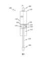
図1は、流体ダンパ100の一実施形態の、ストローク軸Hに沿った縦断面概略図を示す。 FIG. 1 shows a longitudinal cross-sectional schematic view along stroke axis H of one embodiment of a
流体ダンパ100には、例えば正圧ガスなどの減衰流体(図示せず)が充填されたシリンダ110と、ストローク軸Hに沿ってシリンダ110内で移動可能に導かれるピストン基体120と、シリンダ110の外殻壁113から離間された弁体130と、が設けられる。 The
ピストン基体120は、シリンダ110の内部空間を、ストローク軸Hに沿って前方空間111と後方空間112とに分割する。ピストン基体120には、前方空間111と後方空間112とを流体導通する少なくとも1つの流路(図示せず)が設けられている。 The
流体ダンパ100には、ピストン基体120に取り付けられ、シリンダ110の外殻壁113に対してピストン基体120を流体密封し、ストローク軸Hを取り囲むシール122が設けられる。 The
弁体130は、少なくとも1つの流路121の閉鎖を解除する開位置と、少なくとも1つの流路121を閉鎖する閉位置との間で、ピストン基体120に対してストローク軸Hに沿って移動可能に導かれるように構成される。 The
流体ダンパ100には、弁体130とピストン基体120との間に配置される、例えば圧縮コイルばね等のばね部材150が設けられる。ばね部材150は、弁体130をストローク軸Hに沿って開位置に付勢する。弁体130は、正圧が切換圧力を超えたとき、後方空間112に対する前方空間111内の正圧によって、ばね部材150に抗して開位置から閉位置に移動可能に構成される。 The
ばね部材150は、ピストン基体120の凹部123内、例えばストローク軸Hと同軸の穴内に配置される。 The
流体ダンパ100には、ピストン基体120に固定され、後方空間112を通ってシリンダ110から導出されるピストンロッド170が設けられる。 The
ピストンロッド170の、ピストン基体120に取り付けられていない側の端部、並びに、シリンダ110の、ピストンロッド170がシリンダ110から導出されない側の端部のそれぞれには、流体ダンパ100を他の部品、例えば車両のフラップやシャシーに機械的に接続するために、例えば球状ソケット等の接続部材180が配置される。 The
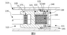
図2は、開位置にある流体ダンパ100の切換ピストンの一実施形態の、ストローク軸に沿った縦断面概略図を示す。図1に示した構成要素には図1と同じ参照記号を付し、再度の説明は省略する。 FIG. 2 shows a longitudinal cross-sectional schematic view along the stroke axis of one embodiment of the switching piston of the
図2は、ピストン基体120内において、前方空間111と後方空間112とを流体導通するように接続する流路121を示している。流路121は、例えば、ストローク軸Hに対して半径方向に設けられるボアを備える。ボアは、ばね部材150が配置される凹部123と後方空間112とを流体導通するように接続する。 FIG. 2 shows a
図2に示す流体ダンパ100には、ピストン基体120に固定され、弁体130とシリンダ110の外殻壁113との間に配置されるガイド部材140が設けられる。ガイド部材140は、例えばストローク軸Hと同軸のガイドスリーブ等である。ガイド部材140は、図2に示す開位置と閉位置との間で、弁体130をストローク軸Hに沿って移動可能に導く。 The
ガイド部材140には、ストッパ141が設けられる。ストッパ141は、例えば、ストローク軸Hを取り囲み、ストローク軸Hに向かって配向された突出部であり、ピストン基体120に対する閉位置から開位置への開方向における弁体130の移動を制限する。 A
図2に示す実施形態では、ピストン基体120は、ストローク軸Hに対して半径方向にピストンロッド170を部分的に囲んでいる。ピストン基体120は、ピストンロッド170の溝171内に、ストローク軸Hに向かって成形することによって固定される。 2, the
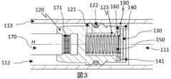
図3は、流体ダンパ100において閉位置にある切換ピストンの別の実施形態について、ストローク軸Hに沿った縦断面概略図を示す。図1または図2に示した構成要素には同じ参照記号を付し、再度の説明は省略する。 FIG. 3 shows a longitudinal cross-sectional schematic view along the stroke axis H of another embodiment of the switching piston in the closed position in the
図3に示す流体ダンパ100には、ピストン基体120上でガイド部材140を支持するための支持部材190が設けられる。支持部材190は、例えば、ラッチ接続部を介してピストン基体120に接続され、ガイド部材140に対して確実に接続される。 The
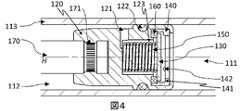
図4は、流体ダンパ100において閉位置にあるの切換ピストンの別の実施形態について、ストローク軸に沿った縦断面概略図を示す。図1、図2、または図3に示した構成要素には同じ参照記号を付し、再度の説明は省略する。 FIG. 4 shows a longitudinal cross-sectional schematic view along the stroke axis of another embodiment of the switching piston in the closed position in the
図4に示す実施形態では、弁体130用のストッパ141には、例えば3つ等、複数の突起142が設けられ、ストッパ141と弁体130との間の接触面が低減されている。突起142は、例えば、半球状である。 In the embodiment shown in FIG. 4 , the
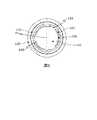
図5は、流体ダンパ100の切換ピストンの別の実施形態について、ストローク軸Hに沿った平面概略図を示す。図1、図2、図3、図4に示した構成要素には同じ参照記号を付し、再度の説明は省略する。 FIG. 5 shows a schematic plan view along stroke axis H of another embodiment of the switching piston of
図5では、弁体130は、ストローク軸Hから半径方向外向きに延びる中央領域131を有している。中央領域131は、開口が設けられないように、すなわち、ストローク軸Hに沿って開口を有しないように形成される。 5, the
図5に示す弁体130には、中央領域131の外側において、ストローク軸Hに沿って、弁体130を通る減衰流体用の多数の開口部132が、例えば3つ設けられている。開口部132は、例えばリングセグメント形状であり、ストローク軸Hから外側に向かって半径方向に開口する。 The
隣接する開口部132の間には、ブリッジ133がそれぞれ配置される。ブリッジ133は、ガイド部材140上の弁体130を導くように機能する。
100 流体ダンパ
110 シリンダ
111 前方空間
112 後方空間
113 外殻壁
120 ピストン基体
121 流路
122 シール
123 凹部
130 弁体
131 中央領域
132 開口部
133 ブリッジ
140 ガイド部材
141 ストッパ
142 突起部
150 ばね部材
160 シール部材
170 ピストンロッド
171 溝
180 接続部材
190 支持部材
H ストローク軸
100
Claims (13)
Translated fromJapaneseb.ストローク軸(H)に沿って前記シリンダ(110)内で移動可能に導かれるピストン基体(120)と、
c.前記シリンダ(110)の外殻壁(113)から離間された弁体(130)と、
を備えた流体ダンパ(100)であって、
d.前記ピストン基体(120)は、前記シリンダ(110)の内部空間を、前記ストローク軸(H)に沿って前方空間(111)と後方空間(112)とに分割し、
e.前記流体ダンパ(100)には、前記ピストン基体(120)内に配置され、前記前方空間(111)と前記後方空間(112)とを流体導通するように接続する少なくとも1つの流路(121)が設けられ、
f.前記弁体(130)は、前記少なくとも1つの流路(121)の閉鎖を解除する開位置と、前記少なくとも1つの流路(121)を閉鎖する閉位置との間で、前記ピストン基体(120)に対して前記ストローク軸(H)に沿って移動可能に導かれ、
g.前記弁体(130)は、前記ストローク軸(H)から半径方向外向きに延びる、開口していない中央領域(131)を有し、
h.前記流体ダンパ(100)は、前記ピストン基体(120)に対する前記閉位置から前記開位置への開方向における前記弁体(130)の移動を制限するために、前記ピストン基体(120)に取り付けられるストッパ(141)を備え、
i.前記ストッパ(141)は、前記ストッパ(141)と前記弁体(130)との間の接触面を減らすために、複数の半球状または円錐状のテーパ状の突起部(142)を備えることを特徴とする、流体ダンパ(100)。a. a cylinder (110) filled with damping fluid;
b. a piston body (120) movably guided within said cylinder (110) along a stroke axis (H);
c. a valve body (130) spaced from a shell wall (113) of said cylinder (110);
A fluid damper (100) comprising:
d. the piston body (120) divides the internal space of the cylinder (110) into a forward space (111) and a rearward space (112) along the stroke axis (H);
e. The fluid damper (100) has at least one channel ( 121) is provided,
f. The valve body (130) moves the piston body between an open position that uncloses the at least one channel (121) and a closed position that closes the at least one channel (121). movably guided along said stroke axis (H) with respect to (120);
g. said valve body (130) has a closed central region (131) extending radially outwardly from said stroke axis (H);
h. the fluid damper (100) is attached to the piston base (120) to limit movement of the valve body (130) in an opening direction from the closed position to the open position relative to the piston base (120); with an attached stopper (141),
i. said stopper (141) comprises a plurality of hemispherical or conical tapered projections (142) to reduce the contact surface between said stopper (141) and said valve body (130); A fluid damper (100), characterized in that:
A flap drive for a motor vehicle comprising at least one motorized drive for moving a flap, said drive being at least one of the claims 1 to 11 for supporting said flap A drive device, characterized in that it comprises one fluid damper (100).
Applications Claiming Priority (4)
| Application Number | Priority Date | Filing Date | Title |
|---|---|---|---|
| DE102021118893 | 2021-07-21 | ||
| DE102021118893.8 | 2021-07-21 | ||
| DE102021125203.2 | 2021-09-29 | ||
| DE102021125203.2ADE102021125203A1 (en) | 2021-07-21 | 2021-09-29 | Fluid damper with a switching piston, method for producing the fluid damper, drive arrangement with the fluid damper |
Publications (1)
| Publication Number | Publication Date |
|---|---|
| JP2023016714Atrue JP2023016714A (en) | 2023-02-02 |
Family
ID=82403475
Family Applications (1)
| Application Number | Title | Priority Date | Filing Date |
|---|---|---|---|
| JP2022109769APendingJP2023016714A (en) | 2021-07-21 | 2022-07-07 | Fluid damper with switching piston, method for manufacturing fluid damper and drive unit with fluid damper |
Country Status (4)
| Country | Link |
|---|---|
| US (1) | US12297687B2 (en) |
| EP (1) | EP4130510B1 (en) |
| JP (1) | JP2023016714A (en) |
| CN (1) | CN115681383A (en) |
Families Citing this family (5)
| Publication number | Priority date | Publication date | Assignee | Title |
|---|---|---|---|---|
| CA3105775C (en) | 2018-07-06 | 2023-08-15 | Tim J. BOUNDY | Systems and devices for adjustable door closure control |
| DE102018122135A1 (en)* | 2018-09-11 | 2020-03-12 | Brose Fahrzeugteile Gmbh & Co. Kommanditgesellschaft, Bamberg | Drive arrangement for a flap of a motor vehicle |
| CN115552142B (en)* | 2020-06-02 | 2025-08-22 | 株式会社松美可管理控股公司 | Flow control valves, dampers and steering devices |
| JP2023016714A (en)* | 2021-07-21 | 2023-02-02 | スタビラス ゲ―エムベーハー | Fluid damper with switching piston, method for manufacturing fluid damper and drive unit with fluid damper |
| US20230304347A1 (en)* | 2022-03-23 | 2023-09-28 | Moshun, LLC | Systems and devices for motion control |
Family Cites Families (26)
| Publication number | Priority date | Publication date | Assignee | Title |
|---|---|---|---|---|
| DE1817391A1 (en)* | 1968-12-30 | 1970-07-09 | Schmid Leopold F | Throttle valve, especially for hydraulic vibration dampers |
| US3763970A (en)* | 1970-06-29 | 1973-10-09 | R Anderson | Adjustable shock absorber |
| US4342884A (en)* | 1978-06-14 | 1982-08-03 | Itsuki Ban | Piston unit |
| US4356898A (en)* | 1979-11-20 | 1982-11-02 | Maremont Corporation | Valve assembly and reduced harshness shock absorber embodying the same |
| JPS6124847A (en)* | 1984-07-13 | 1986-02-03 | Komatsuzaki Kenkiyuushitsu:Kk | Hydraulic buffer |
| SU1629643A1 (en)* | 1986-06-10 | 1991-02-23 | Гродненское Производственное Объединение "Химволокно" Им.60-Летия Ссср | Liquid damper |
| DE3923512A1 (en) | 1989-07-15 | 1991-01-24 | Stabilus Gmbh | SHOCK VALVE WITH STRONG PROGRESSIVE STEEL CHARACTERISTICS, ESPECIALLY FOR STEERING DAMPERS FOR MOTORCYCLES |
| EP0447517B1 (en)* | 1989-09-11 | 1994-05-25 | Stabilus GmbH | Self-blocking gas spring with temperature-responsive bypass valve |
| CA2120862C (en)* | 1993-04-30 | 1997-03-18 | Mark A. Popjoy | Self-blocking gas spring with temperature-responsive bypass valve |
| DE19604721A1 (en) | 1995-02-10 | 1996-08-14 | New Joules Engineering Sales P | Shock-damper for rail-track brake |
| DE19649836C2 (en) | 1996-12-02 | 1999-03-18 | Stabilus Gmbh | Gas spring with braking device |
| US6047797A (en)* | 1997-03-11 | 2000-04-11 | Fichtel & Sachs Industries, Inc. | Emergency locking gas spring |
| DE10140580A1 (en) | 2000-12-16 | 2002-06-20 | Stabilus Gmbh | Piston-cylinder unit has axially moving piston rd, cylinder filled with damping medium, pre-tensioned valve |
| DE20107426U1 (en) | 2001-04-30 | 2001-08-30 | Zimmer, Günther Stephan, 77866 Rheinau | Brake controller with air or liquid damping, in particular for damping the end position of drawers, doors or the like. Facilities |
| DE102004014395B4 (en) | 2003-04-16 | 2015-10-29 | Zf Friedrichshafen Ag | Vibration damper with a piston rod side bypass channel |
| DE102006030064A1 (en) | 2006-06-29 | 2008-01-03 | Stabilus Gmbh | Piston cylinder unit for using a piston to separate operating spaces on the side of a piston-rod and away from it has a piston rod moving on-axis inside a cylinder filled with an absorbing medium |
| DE202006015153U1 (en)* | 2006-10-10 | 2008-02-28 | Kiekert Ag | Damper drive for motor vehicles in particular |
| BRPI1001136A8 (en)* | 2010-04-01 | 2017-09-12 | Magneti Marelli Cofap Fabricadora De Pecas Ltda | TRACTION CONTROL VALVE FOR HYDRAULIC SHOCK ABSORBER |
| AT513330B1 (en)* | 2012-08-27 | 2017-04-15 | Blum Gmbh Julius | Damping device for movable furniture parts |
| DE102016223486A1 (en) | 2016-01-27 | 2017-07-27 | Suspa Gmbh | Fluid-filled piston-cylinder unit |
| KR102627182B1 (en)* | 2017-02-06 | 2024-01-19 | 에이치엘만도 주식회사 | Frequency sensitive type shock absorber |
| JP6853707B2 (en)* | 2017-03-24 | 2021-03-31 | Kyb株式会社 | Shock absorber |
| DE102018221224B4 (en)* | 2018-12-07 | 2020-08-06 | Zf Friedrichshafen Ag | Damping valve for a vibration damper |
| AT523688A1 (en) | 2020-04-02 | 2021-10-15 | Stiwa Automation Gmbh | Hydraulic shock absorber, as well as procedures for assembling a shock absorber |
| JP2023016714A (en)* | 2021-07-21 | 2023-02-02 | スタビラス ゲ―エムベーハー | Fluid damper with switching piston, method for manufacturing fluid damper and drive unit with fluid damper |
| JP2025024847A (en)* | 2023-08-08 | 2025-02-21 | Mfオプテックス株式会社 | Anti-reflection film and optical component provided with the same |
- 2022
- 2022-07-07JPJP2022109769Apatent/JP2023016714A/enactivePending
- 2022-07-11EPEP22184161.2Apatent/EP4130510B1/enactiveActive
- 2022-07-11USUS17/861,327patent/US12297687B2/enactiveActive
- 2022-07-21CNCN202210859056.7Apatent/CN115681383A/enactivePending
Also Published As
| Publication number | Publication date |
|---|---|
| US12297687B2 (en) | 2025-05-13 |
| US20230039706A1 (en) | 2023-02-09 |
| EP4130510A1 (en) | 2023-02-08 |
| EP4130510B1 (en) | 2023-12-27 |
| CN115681383A (en) | 2023-02-03 |
Similar Documents
| Publication | Publication Date | Title |
|---|---|---|
| JP2023016714A (en) | Fluid damper with switching piston, method for manufacturing fluid damper and drive unit with fluid damper | |
| CN112648322B (en) | Damping valve device for vibration damper | |
| US7743896B2 (en) | Shock absorber having a continuously variable semi-active valve | |
| US4110868A (en) | Air damper | |
| US7958979B2 (en) | Variable damper | |
| CN104919207B (en) | There is the hydraulic suspension damper of the damper assembly relevant to position | |
| RU2519328C2 (en) | Built-in quick-action shutoff valve | |
| CN109404472B (en) | Shock absorber assembly | |
| US9388877B2 (en) | Pressure shock absorbing apparatus | |
| CN105940239B (en) | Controllable vibration dampers for motor vehicles | |
| US6655512B2 (en) | Variable area low speed orifice in a vehicle damper | |
| JP6212551B2 (en) | Dual range damping system for shock absorber | |
| CN114810911B (en) | Stroke dependent damper assembly | |
| GB2342423A (en) | A stroke dependent shock absorber for a vehicle suspension | |
| US20160025181A1 (en) | Shock absorber with frequency dependent passive valve | |
| US20210108703A1 (en) | Restriction for a vibration damper | |
| JPH09257081A (en) | Shock absorber | |
| WO2014149527A1 (en) | Rod guide arrangement for electronically controlled valve applications | |
| US8931603B2 (en) | Damper | |
| EP3633229A1 (en) | Shock absorber | |
| US20020063023A1 (en) | Digressive piston compression valve | |
| JP6618996B2 (en) | Valve device | |
| CN113958645A (en) | Damping valve device for vibration damper | |
| US6390257B1 (en) | Suspension damper having piston plate with coined, continuously curved bypass | |
| KR20050079877A (en) | Hydraulic damper |
Legal Events
| Date | Code | Title | Description |
|---|---|---|---|
| A621 | Written request for application examination | Free format text:JAPANESE INTERMEDIATE CODE: A621 Effective date:20250228 |