JP2023015105A - Patient Interface Elbow Assemblies, Asphyxiation Valves and Connectors for Elbow Assemblies - Google Patents
Patient Interface Elbow Assemblies, Asphyxiation Valves and Connectors for Elbow AssembliesDownload PDFInfo
- Publication number
- JP2023015105A JP2023015105AJP2022169076AJP2022169076AJP2023015105AJP 2023015105 AJP2023015105 AJP 2023015105AJP 2022169076 AJP2022169076 AJP 2022169076AJP 2022169076 AJP2022169076 AJP 2022169076AJP 2023015105 AJP2023015105 AJP 2023015105A
- Authority
- JP
- Japan
- Prior art keywords
- headgear
- edge
- socket
- flap
- fabric
- Prior art date
- Legal status (The legal status is an assumption and is not a legal conclusion. Google has not performed a legal analysis and makes no representation as to the accuracy of the status listed.)
- Granted
Links
Images


Classifications
- A—HUMAN NECESSITIES
- A61—MEDICAL OR VETERINARY SCIENCE; HYGIENE
- A61M—DEVICES FOR INTRODUCING MEDIA INTO, OR ONTO, THE BODY; DEVICES FOR TRANSDUCING BODY MEDIA OR FOR TAKING MEDIA FROM THE BODY; DEVICES FOR PRODUCING OR ENDING SLEEP OR STUPOR
- A61M16/00—Devices for influencing the respiratory system of patients by gas treatment, e.g. ventilators; Tracheal tubes
- A61M16/06—Respiratory or anaesthetic masks
- A61M16/0683—Holding devices therefor
- A—HUMAN NECESSITIES
- A61—MEDICAL OR VETERINARY SCIENCE; HYGIENE
- A61M—DEVICES FOR INTRODUCING MEDIA INTO, OR ONTO, THE BODY; DEVICES FOR TRANSDUCING BODY MEDIA OR FOR TAKING MEDIA FROM THE BODY; DEVICES FOR PRODUCING OR ENDING SLEEP OR STUPOR
- A61M16/00—Devices for influencing the respiratory system of patients by gas treatment, e.g. ventilators; Tracheal tubes
- A61M16/0057—Pumps therefor
- A61M16/0066—Blowers or centrifugal pumps
- A61M16/0069—Blowers or centrifugal pumps the speed thereof being controlled by respiratory parameters, e.g. by inhalation
- A—HUMAN NECESSITIES
- A61—MEDICAL OR VETERINARY SCIENCE; HYGIENE
- A61M—DEVICES FOR INTRODUCING MEDIA INTO, OR ONTO, THE BODY; DEVICES FOR TRANSDUCING BODY MEDIA OR FOR TAKING MEDIA FROM THE BODY; DEVICES FOR PRODUCING OR ENDING SLEEP OR STUPOR
- A61M16/00—Devices for influencing the respiratory system of patients by gas treatment, e.g. ventilators; Tracheal tubes
- A61M16/06—Respiratory or anaesthetic masks
- A61M16/0605—Means for improving the adaptation of the mask to the patient
- A61M16/0633—Means for improving the adaptation of the mask to the patient with forehead support
- A—HUMAN NECESSITIES
- A61—MEDICAL OR VETERINARY SCIENCE; HYGIENE
- A61M—DEVICES FOR INTRODUCING MEDIA INTO, OR ONTO, THE BODY; DEVICES FOR TRANSDUCING BODY MEDIA OR FOR TAKING MEDIA FROM THE BODY; DEVICES FOR PRODUCING OR ENDING SLEEP OR STUPOR
- A61M16/00—Devices for influencing the respiratory system of patients by gas treatment, e.g. ventilators; Tracheal tubes
- A61M16/08—Bellows; Connecting tubes ; Water traps; Patient circuits
- A61M16/0816—Joints or connectors
- A61M16/0825—Joints or connectors with ball-sockets
- A—HUMAN NECESSITIES
- A61—MEDICAL OR VETERINARY SCIENCE; HYGIENE
- A61M—DEVICES FOR INTRODUCING MEDIA INTO, OR ONTO, THE BODY; DEVICES FOR TRANSDUCING BODY MEDIA OR FOR TAKING MEDIA FROM THE BODY; DEVICES FOR PRODUCING OR ENDING SLEEP OR STUPOR
- A61M16/00—Devices for influencing the respiratory system of patients by gas treatment, e.g. ventilators; Tracheal tubes
- A61M16/20—Valves specially adapted to medical respiratory devices
- A61M16/208—Non-controlled one-way valves, e.g. exhalation, check, pop-off non-rebreathing valves
- A—HUMAN NECESSITIES
- A61—MEDICAL OR VETERINARY SCIENCE; HYGIENE
- A61M—DEVICES FOR INTRODUCING MEDIA INTO, OR ONTO, THE BODY; DEVICES FOR TRANSDUCING BODY MEDIA OR FOR TAKING MEDIA FROM THE BODY; DEVICES FOR PRODUCING OR ENDING SLEEP OR STUPOR
- A61M2205/00—General characteristics of the apparatus
- A61M2205/42—Reducing noise
- A—HUMAN NECESSITIES
- A61—MEDICAL OR VETERINARY SCIENCE; HYGIENE
- A61M—DEVICES FOR INTRODUCING MEDIA INTO, OR ONTO, THE BODY; DEVICES FOR TRANSDUCING BODY MEDIA OR FOR TAKING MEDIA FROM THE BODY; DEVICES FOR PRODUCING OR ENDING SLEEP OR STUPOR
- A61M2207/00—Methods of manufacture, assembly or production
- A—HUMAN NECESSITIES
- A61—MEDICAL OR VETERINARY SCIENCE; HYGIENE
- A61M—DEVICES FOR INTRODUCING MEDIA INTO, OR ONTO, THE BODY; DEVICES FOR TRANSDUCING BODY MEDIA OR FOR TAKING MEDIA FROM THE BODY; DEVICES FOR PRODUCING OR ENDING SLEEP OR STUPOR
- A61M2209/00—Ancillary equipment
- A61M2209/06—Packaging for specific medical equipment
Landscapes
- Health & Medical Sciences (AREA)
- Pulmonology (AREA)
- Heart & Thoracic Surgery (AREA)
- Engineering & Computer Science (AREA)
- Anesthesiology (AREA)
- Biomedical Technology (AREA)
- Emergency Medicine (AREA)
- Hematology (AREA)
- Life Sciences & Earth Sciences (AREA)
- Animal Behavior & Ethology (AREA)
- General Health & Medical Sciences (AREA)
- Public Health (AREA)
- Veterinary Medicine (AREA)
- Respiratory Apparatuses And Protective Means (AREA)
Abstract
Translated fromJapaneseDescription
Translated fromJapanese参照する開示
本開示は、2015年7月31日に出願された米国特許出願第62/199,513号明細書、2015年7月31日に出願された米国特許出願第62/199,547号明細書、2015年8月25日に出願された米国特許出願第62/209,822号明細書、2015年9月24日に出願された米国特許出願第62/232,293号明細書、2016年3月8日に出願された米国特許出願第62/305,284号明細書、2016年7月6日に出願された米国特許出願第62/358,790号明細書、および2016年7月8日に出願された米国特許出願第62/360,052号明細書のさまざまな特徴を参照する。それらの出願の開示全体が、それらが含むすべてに対して、本明細書に完全に示されているかのように本出願の一部とされ、すべての目的で参照により援用される。REFERENCE DISCLOSURE This disclosure is directed to U.S. Patent Application No. 62/199,513, filed July 31, 2015, U.S. Patent Application No. 62/199,547, filed July 31, 2015. Specification, U.S. Patent Application No. 62/209,822 filed Aug. 25, 2015, U.S. Patent Application No. 62/232,293 filed Sep. 24, 2015, 2016 U.S. Patent Application No. 62/305,284, filed March 8, 2016; U.S. Patent Application No. 62/358,790, filed July 6, 2016; See various features of US patent application Ser. No. 62/360,052, filed Aug. 8. The entire disclosures of those applications, for all that they contain, are hereby incorporated by reference into this application as if fully set forth herein and are incorporated by reference for all purposes.
開示の分野
本発明は、概して呼吸療法用の患者インタフェースに関する。本発明は、概して、陽圧下で呼吸ガスを供給するために使用者の鼻および口のうちの少なくとも一方を覆うフェイスマスク等の患者インタフェースのエルボアセンブリに関する。より詳細には、本発明は、何らかの理由で呼吸ガス供給のスイッチが切られるかまたは呼吸ガス供給が停止した場合に、使用者が呼吸し続けるのを可能にするように配置された窒息防止弁(AA弁)を有する、こうしたエルボアセンブリに関する。本発明はまた、エルボアセンブリ、好ましくは本明細書に開示するエルボアセンブリ等を介して、患者インタフェースに導管を接続するためのコネクタに関する。本発明はまた、使用者の頭部に呼吸マスクを固定するために使用されるヘッドギアに関する。FIELD OF THE DISCLOSURE The present invention relates generally to patient interfaces for respiratory therapy. The present invention relates generally to patient interface elbow assemblies, such as face masks, over at least one of a user's nose and mouth to provide breathing gas under positive pressure. More particularly, the present invention provides an anti-asphyxia valve positioned to allow the user to continue breathing if for any reason the breathing gas supply is switched off or stopped. (AA valve). The present invention also relates to a connector for connecting a conduit to a patient interface via an elbow assembly, preferably such as the elbow assemblies disclosed herein. The present invention also relates to headgear used to secure a respiratory mask to a user's head.
呼吸療法用の患者インタフェースとともに使用される多くのタイプのヘッドギアがある。しかしながら、いくつかの応用(たとえば、閉塞性睡眠時無呼吸(OSA)の治療)では、患者インタフェースはしばしばかつ/または長期間装着されるため、インタフェースの封止機能を維持するかまたは向上させながら、使用者に対する利便性および快適さを向上させる継続的な改善が必要である。 There are many types of headgear used with patient interfaces for respiratory therapy. However, in some applications (e.g., treatment of obstructive sleep apnea (OSA)), the patient interface is worn often and/or for long periods of time, thus maintaining or improving the sealing function of the interface. , continuous improvements are needed to increase convenience and comfort for users.
陽圧下で使用者に呼吸ガスを提供するために、フェイスマスクを用いることができる。使用者の口および鼻の両方が覆われる構成では、フルフェイスマスクは、通常、鼻梁の上に覆い被さる。一般に、単一シールが使用者の鼻および口の周囲を囲む。 A face mask can be used to provide breathing gases to the user under positive pressure. In configurations where both the user's mouth and nose are covered, the full face mask typically drapes over the bridge of the nose. Generally, a single seal surrounds the user's nose and mouth.
こうしたフルフェイスマスクは、一般に、ヘッドギアによって使用者の頭部に固定される。実質的に漏れを低減させるために、ヘッドギアは、通常締め付けられ、それにより、使用者の鼻梁に高い圧力がかけられることになる。言い換えれば、ヘッドギアが締め付けられるに従い、シールは、通常、鼻梁に徐々に増大する負荷を加える。こうしたマスクには、通常、エルボアセンブリが設けられており、それは、90度に延在する管状導管を備え、導管の一端はマスクに流体連通し、導管の他端は呼吸ガス送達チューブに接続されている。こうしたエルボアセンブリにおけるAA弁が完全にまたは確実に開閉しないことが問題である可能性がある。 Such full-face masks are generally secured to the user's head by headgear. To substantially reduce leakage, headgear is usually tightened, which puts high pressure on the bridge of the user's nose. In other words, as the headgear is tightened, the seal typically applies a gradually increasing load to the bridge of the nose. Such masks are typically provided with an elbow assembly that includes a tubular conduit extending 90 degrees, one end of which is in fluid communication with the mask and the other end of which is connected to a respiratory gas delivery tube. ing. It can be a problem that the AA valves in such elbow assemblies do not fully or reliably open and close.
多種多様の呼吸マスクが考案された。これらのマスクの多くは、使用者の鼻および/または口の一部の周囲を封止することにより、使用者の気道との封止連通を提供するように構成されている。これらのマスクは、一般に、限定されないが非侵襲的換気(NIV)および持続気道陽圧(CPAP)等の治療を提供するために使用される。CPAP療法は、一般に、閉塞性睡眠時無呼吸(OSA)を治療するために使用され、使用者の気道に加圧空気の一定供給を提供することを含む。これは、気道を開放した状態で支え、したがって、気道虚脱を最小限にし、無呼吸を低減させる。この治療の一部として、バイアス流排気システムを用いて、マスク内から呼気二酸化炭素(CO2)がフラッシングされ、それにより、再吸入する可能性が低減するかまたはなくなる。A wide variety of respiratory masks have been devised. Many of these masks are configured to provide a sealed communication with the user's airway by sealing around a portion of the user's nose and/or mouth. These masks are commonly used to provide therapies such as, but not limited to, non-invasive ventilation (NIV) and continuous positive airway pressure (CPAP). CPAP therapy is commonly used to treat obstructive sleep apnea (OSA) and involves providing a constant supply of pressurized air to a user's airways. This holds the airway open, thus minimizing airway collapse and reducing apnea. As part of this treatment, a bias flow exhaust system is used to flush exhaled carbon dioxide (CO2 ) from within the mask, thereby reducing or eliminating the possibility of rebreathing.
バイアス流排気システムは、認識できる騒音の原因となる可能性がある。通風が、使用者および使用者の同床者の両方またはいずれか一方に対して不快である可能性があり、治療のコンプライアンスが低下することになる可能性がある。バイアス流排気システムはまた、清掃が困難である可能性もあり、それにより、汚染がもたらされるかまたは治療のコンプライアンスが低下する可能性がある。こうしたバイアス流排気システムはまた、呼吸マスクのかさを増加させる可能性もあり、呼吸マスクを装着している間の使用者の快適さがさらに低減し、したがって、使用者のコンプライアンスの可能性がさらに低下する。 Bias flow exhaust systems can contribute to perceptible noise. Draft can be uncomfortable for the user and/or the user's bedmates and can lead to reduced compliance with treatment. Bias-flow exhaust systems can also be difficult to clean, which can lead to contamination or reduced treatment compliance. Such bias flow exhaust systems can also increase the bulk of the respirator, further reducing user comfort while wearing the respirator and thus increasing the likelihood of user compliance. descend.
現行のヘッドギアに関連して体験される他の一般的な問題としては、ヘッドギアが、非常に重量があり、かさばりかつ高温であり、それが使用者に不快である可能性がある、ということが挙げられる。従来の材料から作製されたヘッドギアは、洗浄した後に乾燥が遅い可能性がある。これは患者に影響を与える可能性があり、それは、ヘッドギアは多くの場合、1日で乾かず、患者は自身のマスクを装着しないか、または湿ったヘッドギアでマスクを装着することを余儀なくされるためである。ヘッドギアの清掃に関連するこの不都合により、患者によってはヘッドギアをまったく洗浄しないように選択することになる可能性があり、それは非衛生的になる可能性がある。 Another common problem experienced with current headgear is that the headgear is very heavy, bulky and hot, which can be uncomfortable for the user. mentioned. Headgear made from conventional materials can be slow to dry after washing. This can affect patients, which often do not dry in a day, and patients are forced to either not wear their own mask or wear a mask with damp headgear. It's for. This inconvenience associated with cleaning the headgear can lead some patients to choose not to clean the headgear at all, which can be unhygienic.
本開示の目的は、少なくとも上述したことを改善するのにいくらか助けになるか、または少なくとも公衆もしくは医療専門家に有用な選択肢を提供する、1つまたは複数の構造および/または方法を提供することである。本開示はまた、呼吸マスク用のバイアス流排気システムに関する。こうしたバイアス流排気システムは、清掃の容易さを向上させ、騒音を低減させ、かつ/または呼吸マスクの小型化を促進しながら、排気を拡散させるように構成される。本開示の目的は、少なくとも公衆に有用な選択肢を提供する、バイアス流排気システムを備えた呼吸マスクを提供することである。 It is an object of the present disclosure to provide one or more structures and/or methods that help in some way to remedy at least the above, or at least provide the public or medical professionals with a useful choice. is. The present disclosure also relates to bias flow evacuation systems for respiratory masks. Such bias flow exhaust systems are configured to diffuse exhaust air while improving ease of cleaning, reducing noise, and/or facilitating smaller respirator sizes. It is an object of the present disclosure to provide a respirator with a bias flow exhaust system that at least provides the public with a useful choice.
本発明の態様によれば、マスクアセンブリを空気および/または他のガスの導管に接続するように構成されたエルボアセンブリが提供され、エルボアセンブリは、エルボおよびスリーブを備え、エルボは、内壁および外壁を備えかつそれらの間に空気流路を画定し、内壁はエルボの側部にポートを備え、スリーブはエルボに結合され、スリーブはフラップを備え、フラップが第1位置にあるとき、フラップは、少なくとも部分的にポートを閉鎖し、空気導管からのガスがエルボを介して使用者まで進むのを可能にし、フラップが第2位置にあるとき、フラップは、少なくとも部分的に空気導管を閉鎖し、それにより、ガスが使用者からポートおよび空気流路を介してエルボアセンブリの外側の位置まで流れるのを可能にし、空気流路は、空気をエルボの側部から離れるように向け、フラップは細長いビードを備え、細長いビードは、フラップから突出し、フラップが第1位置にあるときにエルボの内壁と接触して、フラップをエルボの内壁から間隔を空けて配置するように構成され、ビードは、フラップを側面から見た場合にビードの一部がビードの別の部分よりフラップからさらに突出するように構成された、少なくとも1つのテーパ状部分を備える。 According to an aspect of the present invention, there is provided an elbow assembly configured to connect a mask assembly to air and/or other gas conduits, the elbow assembly comprising an elbow and a sleeve, the elbow having inner and outer walls. and defining an air flow path therebetween, the inner wall comprising a port on the side of the elbow, a sleeve coupled to the elbow, the sleeve comprising a flap, and when the flap is in the first position, the flap comprises: at least partially closing the port and allowing gas from the air conduit to pass through the elbow to the user, the flap at least partially closing the air conduit when the flap is in the second position; Gas is thereby allowed to flow from the user through the ports and air passages to locations outside the elbow assembly, the air passages directing the air away from the sides of the elbow, and the flaps are elongated beads. an elongated bead projecting from the flap and configured to contact the inner wall of the elbow to space the flap from the inner wall of the elbow when the flap is in the first position; At least one tapered portion is configured such that a portion of the bead protrudes further from the flap than another portion of the bead when viewed from the side.
いくつかの実施形態では、ビードは、弁フラップの周縁部の少なくとも一部に延在している。 In some embodiments, the bead extends around at least a portion of the periphery of the valve flap.
いくつかの実施形態では、ビードは、弁フラップの周縁部全体に延在している。 In some embodiments, the bead extends around the entire circumference of the valve flap.
いくつかの実施形態では、フラップは、フラップをエルボに枢支取付するヒンジを備えることができ、ビードは、フラップの周縁部にわたってヒンジまで延在している。 In some embodiments, the flap can include a hinge that pivotally attaches the flap to the elbow, and the bead extends around the periphery of the flap to the hinge.
いくつかの実施形態では、ビードは、ヒンジから遠い方の弓形ビード部分を含み、弓形ビード部分は、フラップを平面で見た場合、弓形である。 In some embodiments, the bead includes an arcuate bead portion distal from the hinge, the arcuate bead portion being arcuate when the flap is viewed in plan.
いくつかの実施形態では、ビードは、ヒンジに隣接する少なくとも1つの直線状(linear)ビード部分を含み、上記ビード部分は、フラップを平面で見た場合、まっすぐ(straight)である。 In some embodiments, the bead includes at least one linear bead portion adjacent to the hinge, said bead portion being straight when the flap is viewed in plan.
いくつかの実施形態では、少なくとも1つの直線状ビード部分は、ビードの残りの部分の幅より広い封止面を含む。 In some embodiments, at least one linear bead portion includes a sealing surface that is wider than the remainder of the bead.
いくつかの実施形態では、少なくとも1つの直線状ビード部分の幅は、フラップが第1位置にあるとき、少なくとも1つの直線状ビード部分が封止するエルボアセンブリの別の部分の表面の高さと実質的に同一である。 In some embodiments, the width of the at least one linear bead portion is substantially the same as the height of the surface of another portion of the elbow assembly that the at least one linear bead portion seals to when the flap is in the first position. are essentially identical.
いくつかの実施形態では、少なくとも1つの直線状ビード部分とフラップの残りの部分との間に、遷移壁が画定され、遷移壁は、直線状ビード部分のへりからフラップの本体まで延在し、遷移壁は、フラップに構造的剛性を提供するように構成されている。 In some embodiments, a transition wall is defined between the at least one linear bead portion and the remaining portion of the flap, the transition wall extending from an edge of the linear bead portion to the body of the flap; The transition wall is configured to provide structural rigidity to the flap.
いくつかの実施形態では、遷移壁は、弁フラップの平面に対して傾斜している。 In some embodiments, the transition wall is angled with respect to the plane of the valve flap.
いくつかの実施形態では、ビードは、フラップを平面で見た場合、実質的に「n」字型の形状である。 In some embodiments, the bead is substantially "n" shaped when viewed in plan with the flap.
いくつかの実施形態では、ビードは、フラップを平面で見た場合、実質的に「D」字型の形状である。 In some embodiments, the bead is substantially "D" shaped when the flap is viewed in plan.
いくつかの実施形態では、ビードは、ヒンジから遠い方の位置からヒンジに隣接する位置まで弁フラップに向かって内向きにテーパ状であり、すなわち、ビードは、ヒンジから遠い方の位置でフラップからさらに突出している。 In some embodiments, the bead tapers inwardly toward the valve flap from a location distal to the hinge to a location adjacent the hinge, i.e., the bead tapers away from the flap at a location distal to the hinge. It stands out even more.
いくつかの実施形態では、ビードは、ヒンジに隣接する位置で、弁フラップに融合するようにテーパ状である。 In some embodiments, the bead is tapered to merge with the valve flap adjacent the hinge.
いくつかの実施形態では、ビードは、フラップが第1位置にあるときにエルボの内壁と接触する上面と、弁フラップと上面との間に延在する対向する側壁とを備え、上面は封止面を形成している。 In some embodiments, the bead comprises a top surface that contacts the inner wall of the elbow when the flap is in the first position and opposing sidewalls that extend between the valve flap and the top surface, the top surface sealing forms a surface.
いくつかの実施形態では、少なくとも1つの側壁は湾曲している。 In some embodiments, at least one sidewall is curved.
いくつかの実施形態では、1つの側壁の形状は別の側壁の形状と異なる。 In some embodiments, the shape of one sidewall differs from the shape of another sidewall.
いくつかの実施形態では、1つの側壁の輪郭は、側壁が上面から弁フラップの平面内に湾曲するようなものである。 In some embodiments, the profile of one sidewall is such that the sidewall curves from the top surface into the plane of the valve flap.
いくつかの実施形態では、少なくとも1つの側壁は、輪郭が実質的にまっすぐであり、それにより、その側壁は、上面と弁フラップとの間にまっすぐな線で延在する。 In some embodiments, at least one sidewall is substantially straight in profile such that the sidewall extends in a straight line between the top surface and the valve flap.
いくつかの実施形態では、まっすぐな側壁は、弁フラップの平面に対して傾斜している。 In some embodiments, the straight sidewalls are angled with respect to the plane of the valve flap.
いくつかの実施形態では、ビードは、弁フラップと一体的に形成されている。 In some embodiments, the bead is integrally formed with the valve flap.
いくつかの実施形態では、複数のビードが設けられている。 In some embodiments, multiple beads are provided.
いくつかの実施形態では、エルボアセンブリは、エルボおよびスリーブに対して所望の向きでの支持体および弁フラップの取付を容易にするように配置された方向付け機構をさらに備える。 In some embodiments, the elbow assembly further comprises an orientation mechanism arranged to facilitate attachment of the support and valve flap in a desired orientation relative to the elbow and sleeve.
いくつかの実施形態では、方向付け機構は、支持体およびエルボまたはスリーブのうちの一方のスロットと、支持体およびエルボまたはスリーブのうちの他方の突起とを備え、突起は、支持体および弁フラップが所望の向きに取り付けられたときにスロットに受け入れられる。 In some embodiments, the orientation mechanism comprises a slot in one of the support and the elbow or sleeve and a projection in the other of the support and elbow or sleeve, the projection connecting the support and the valve flap. is received in the slot when installed in the desired orientation.
いくつかの実施形態では、空気流路は2つの空気流路を含む。 In some embodiments, the airflow path includes two airflow paths.
いくつかの実施形態では、スリーブは、スリーブの外面に延在する出っ張りと、出っ張りに隣接する凹部とをさらに備える。 In some embodiments, the sleeve further comprises a ledge extending to the outer surface of the sleeve and a recess adjacent the ledge.
いくつかの実施形態では、出っ張りおよび凹部は、出っ張りと係合するように隆起を組み込んだ旋回構成要素を受け入れるように適合されている。 In some embodiments, the ledge and recess are adapted to receive a pivot component incorporating a ridge to engage the ledge.
いくつかの実施形態では、封止面は、側面から見た場合、実質的にまっすぐである。 In some embodiments, the sealing surface is substantially straight when viewed from the side.
いくつかの実施形態では、封止面は、側面から見た場合、湾曲または傾斜部分を含む。 In some embodiments, the sealing surface includes curved or angled portions when viewed from the side.
いくつかの実施形態では、フラップは、少なくとも第2位置にあるときにエルボから離れてスリーブに向かって付勢されるように構成されている。 In some embodiments, the flap is configured to be biased away from the elbow toward the sleeve when in at least the second position.
いくつかの実施形態では、フラップは、少なくとも第2位置にあるときに第1位置から離れるように付勢されるように構成されている。 In some embodiments, the flap is configured to be biased away from the first position when in at least the second position.
いくつかの実施形態では、フラップは、第1位置からも離れる方向において第2位置から離れるように付勢される。 In some embodiments, the flap is biased away from the second position in a direction also away from the first position.
いくつかの実施形態では、フラップは、フラップのビードに対して反対側の面に凹部を備える。 In some embodiments, the flap comprises a recess on the side of the flap opposite the bead.
いくつかの実施形態では、凹部は長方形である。 In some embodiments, the recess is rectangular.
いくつかの実施形態では、凹部はフラップのヒンジに隣接する。 In some embodiments, the recess is adjacent to the hinge of the flap.
いくつかの実施形態では、ビードは、ヒンジから遠い方の弓形ビード部分を含むことができ、フラップを平面で見た場合、弓形ビード部分は弓形である。ビードは、さらにまたは別法として、ヒンジに隣接する少なくとも1つの直線状ビード部分を含むことができ、フラップを平面で見た場合、上記ビード部分はまっすぐである。一例では、フラップを平面で見た場合、ビードは実質的に「n」字型の形状である。 In some embodiments, the bead can include an arcuate bead portion distal from the hinge, wherein the arcuate bead portion is arcuate when the flap is viewed in plan. The bead may also or alternatively include at least one straight bead portion adjacent the hinge, said bead portion being straight when the flap is viewed in plan. In one example, the bead is substantially "n" shaped when the flap is viewed in plan.
ビードは、ヒンジから遠い方の位置からヒンジに隣接する位置まで弁フラップに向かって内向きにテーパ状となることができ、すなわち、ビードは、ヒンジから遠い方の位置でフラップからさらに突出する。ビードは、ヒンジに隣接する位置で、弁フラップに融合するようにテーパ状となることができる。 The bead may taper inwardly toward the valve flap from a location distal to the hinge to a location adjacent the hinge, ie, the bead projects further from the flap at a location distal to the hinge. The bead may taper to merge with the valve flap adjacent the hinge.
いくつかの実施形態では、ビードは、好ましくは、フラップが第1位置にあるときにエルボの内壁と接触する上面と、弁フラップと上面との間に延在する対向する側壁とを備える。少なくとも1つの側壁は湾曲している場合がある。少なくとも1つの側壁はまっすぐである場合がある。1つの側壁の輪郭形状は別の側壁の形状と異なり得る。一例では、1つの側壁の輪郭は、側壁が上面から弁フラップの平面内に湾曲するようなものである。一例では、少なくとも1つの側壁は、輪郭が実質的にまっすぐであり、それにより、その側壁は、上面と弁フラップとの間にまっすぐな線で延在する。まっすぐな側壁は、弁フラップの平面に対して傾斜している場合がある。 In some embodiments, the bead preferably comprises a top surface that contacts the inner wall of the elbow when the flap is in the first position, and opposing sidewalls that extend between the valve flap and the top surface. At least one sidewall may be curved. At least one sidewall may be straight. The contour shape of one sidewall may differ from the shape of another sidewall. In one example, the profile of one sidewall is such that the sidewall curves from the top surface into the plane of the valve flap. In one example, at least one sidewall is substantially straight in profile such that the sidewall extends in a straight line between the top surface and the valve flap. Straight sidewalls may be angled with respect to the plane of the valve flap.
いくつかの実施形態では、ビードを弁フラップと一体的に形成することができる。複数のビードを設けることができる。 In some embodiments, the bead can be integrally formed with the valve flap. Multiple beads can be provided.
いくつかの実施形態では、フラップは、フラップ支持体を備えることができ、フラップ支持体は、エルボおよびスリーブのうちの少なくとも一方に取り付けられている。方向付け機構を設け、エルボおよびスリーブに対して所望の向きでの支持体および弁フラップの取付を容易にするように配置することができる。方向付け機構は、支持体およびエルボまたはスリーブのうちの一方のスロットと、支持体およびエルボまたはスリーブのうちの他方の突起とを備えることができ、突起は、支持体および弁フラップが所望の向きに取り付けられたときにスロットに受け入れられる。 In some embodiments, the flap can comprise a flap support attached to at least one of the elbow and the sleeve. An orientation mechanism may be provided and positioned to facilitate attachment of the support and valve flap in a desired orientation relative to the elbow and sleeve. The orientation mechanism may comprise a slot in one of the support and elbow or sleeve and a projection on the other of the support and elbow or sleeve, the projection aligning the support and valve flap in the desired orientation. is received in the slot when attached to the
いくつかの実施形態では、流路は2つの空気流路を含むことができる。 In some embodiments, the channels can include two air channels.
いくつかの実施形態では、スリーブは、スリーブの外面に延在する出っ張りと、出っ張りに隣接する凹部とをさらに備えることができる。出っ張りおよび凹部は、出っ張りと係合するように隆起を組み込んだ旋回構成要素を受け入れるように適合され得る。 In some embodiments, the sleeve can further comprise a ledge extending to the outer surface of the sleeve and a recess adjacent the ledge. The ledge and recess may be adapted to receive a pivot component incorporating a ridge to engage the ledge.
本発明の別の態様によれば、マスクアセンブリを空気および/または他のガスの導管に接続するように構成されたエルボアセンブリに取り付けられる、窒息防止弁が提供され、エルボアセンブリは、エルボおよびスリーブを備え、エルボは、内壁および外壁を備えかつそれらの間に空気および/または他のガスの流路を画定し、内壁は、エルボの側部にポートを備え、スリーブはエルボに結合されており、弁は支持体と支持体に枢支取付されたフラップとを備え、弁フラップアセンブリがエルボおよびアセンブリに取り付けられているとき、かつフラップが第1位置にあるとき、フラップは、少なくとも部分的にポートを閉鎖し、導管からのガスがエルボを介して使用者まで進むのを可能にし、フラップが第2位置にあるとき、フラップは、少なくとも部分的に導管を閉鎖し、それにより、ガスが使用者からポートおよび流路を介してエルボアセンブリの外側の位置まで流れるのを可能にし、流路は、空気および/または他のガスをエルボの側部から離れるように向け、フラップは細長いビードを備え、細長いビードは、フラップから突出し、フラップが第1位置にあるときにエルボの内壁と接触して、フラップをエルボの内壁から間隔を空けて配置するように構成され、ビードは、フラップを側面から見た場合、ビードの一部がビードの別の部分よりフラップからさらに突出するように構成された、少なくとも1つのテーパ状部分を備える。 According to another aspect of the invention, there is provided an anti-asphyxia valve mounted on an elbow assembly configured to connect the mask assembly to air and/or other gas conduits, the elbow assembly comprising an elbow and a sleeve. wherein the elbow comprises an inner wall and an outer wall and defines a flow path for air and/or other gas therebetween, the inner wall comprising a port on the side of the elbow, and the sleeve coupled to the elbow. , the valve comprises a support and a flap pivotally attached to the support, the flap being at least partially defined when the valve flap assembly is attached to the elbow and the assembly and when the flap is in the first position; The port is closed to allow gas from the conduit to pass through the elbow to the user, and when the flap is in the second position, the flap at least partially closes the conduit, thereby allowing gas to be used. to a location outside the elbow assembly through ports and channels, the channels directing air and/or other gases away from the sides of the elbow, and the flaps comprising elongated beads. an elongated bead projecting from the flap and configured to contact an inner wall of the elbow to space the flap from the inner wall of the elbow when the flap is in the first position, the bead laterally extending the flap; When viewed, it comprises at least one tapered portion configured such that a portion of the bead protrudes further from the flap than another portion of the bead.
いくつかの実施形態では、細長いビードは、弁フラップの周縁部の少なくとも一部に延在している。 In some embodiments, the elongated bead extends around at least a portion of the periphery of the valve flap.
いくつかの実施形態では、ビードは、弁フラップの周縁部全体に延在している。 In some embodiments, the bead extends around the entire circumference of the valve flap.
いくつかの実施形態では、弁フラップは、弁フラップを導管に枢支結合するヒンジを備え、細長いビードは、フラップの周縁部にわたってヒンジまで延在している。 In some embodiments, the valve flap comprises a hinge that pivotally connects the valve flap to the conduit, and the elongated bead extends around the periphery of the flap to the hinge.
いくつかの実施形態では、細長いビードは、ヒンジから遠い方の弓形ビード部分を含み、弓形ビード部分は、フラップを平面で見た場合、弓形である。 In some embodiments, the elongated bead includes an arcuate bead portion distal from the hinge, the arcuate bead portion being arcuate when the flap is viewed in plan.
いくつかの実施形態では、細長いビードは、ヒンジに隣接する少なくとも1つの直線状ビード部分を含み、少なくとも1つの直線状ビード部分は、フラップを平面で見た場合、まっすぐである。 In some embodiments, the elongate bead includes at least one linear bead portion adjacent the hinge, wherein the at least one linear bead portion is straight when the flap is viewed in plan.
いくつかの実施形態では、少なくとも1つの直線状ビード部分は、細長いビードの残りの部分の幅より広い封止面を含む。 In some embodiments, at least one linear bead portion includes a sealing surface that is wider than the remainder of the elongated bead.
いくつかの実施形態では、少なくとも1つの直線状ビード部分の幅は、フラップが第1位置にあるとき、少なくとも1つの直線状ビード部分が封止する導管の別の部分の表面の高さと実質的に同一である。 In some embodiments, the width of the at least one linear bead portion is substantially the height of the surface of another portion of the conduit that the at least one linear bead portion seals to when the flap is in the first position. is identical to
いくつかの実施形態では、少なくとも1つの直線状ビード部分と弁フラップの残りの部分との間に、遷移壁が画定され、遷移壁は、直線状ビード部分のへりからフラップの本体まで延在し、遷移壁は、フラップに構造的剛性を提供するように構成されている。 In some embodiments, a transition wall is defined between the at least one linear bead portion and the remaining portion of the valve flap, the transition wall extending from an edge of the linear bead portion to the main body of the flap. , the transition wall is configured to provide structural rigidity to the flap.
いくつかの実施形態では、遷移壁は、弁フラップの平面に対して傾斜している。 In some embodiments, the transition wall is angled with respect to the plane of the valve flap.
いくつかの実施形態では、細長いビードは、フラップを平面で見た場合、実質的に「n」字型の形状である。 In some embodiments, the elongated bead is substantially "n" shaped when the flap is viewed in plan.
いくつかの実施形態では、細長いビードは、フラップを平面で見た場合、実質的に「D」字型の形状である。 In some embodiments, the elongated bead is substantially "D" shaped when the flap is viewed in plan.
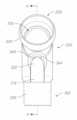
別の態様によれば、空気および/または他のガスの導管を直接または間接的に患者インタフェースに接続するためのコネクタが提供され、コネクタは、第1端部および第2端部と、第1端部と第2端部との間にガス経路を画定する壁とを備える。第1端部は、エルボコネクタに結合するように構成され、第2端部は、呼吸チューブを終端させる、カラー等、チューブコネクタを介する等、呼吸ガスチューブに結合するように構成され、さらに、コネクタの第2端部は、コネクタの第2端部のエルボコネクタへの固定取付を阻止するように構成されている。 According to another aspect, a connector is provided for connecting air and/or other gas conduits directly or indirectly to a patient interface, the connector having first and second ends and a first end. A wall defining a gas path between the end and the second end. The first end is configured to couple to an elbow connector and the second end is configured to couple to a respiratory gas tube, such as via a tube connector, such as a collar, which terminates the respiratory tube, and The second end of the connector is configured to prevent fixed attachment of the second end of the connector to the elbow connector.
好ましくは、コネクタの第2端部は、前記阻止を提供するようにエルボコネクタに対して寸法が決められている。より詳細には、好ましい実施形態によれば、エルボコネクタの係合部分は、コネクタの内側に受け入れられるように構成され、第2端部の内側寸法は、エルボコネクタの係合部分の外側寸法より大きい。 Preferably, the second end of the connector is dimensioned relative to the elbow connector to provide said blocking. More particularly, according to a preferred embodiment, the engaging portion of the elbow connector is configured to be received inside the connector, the inner dimension of the second end being greater than the outer dimension of the engaging portion of the elbow connector. big.
好ましくは、コネクタは、クリックフィットまたはスナップフィットを介してエルボコネクタに解除可能にかつ封止可能に固定されるように構成されている。この目的で、コネクタの表面(好ましくは内面)に突起または凹部を設けることができ、エルボコネクタの係合部分は、対応する凹部または突起を含むことができる。したがって、本発明は、新規性がありかつ進歩性があるコネクタと係合するように構成されたエルボコネクタをさらに提供することができる。 Preferably, the connector is configured to be releasably and sealably secured to the elbow connector via a click fit or snap fit. For this purpose, the surface (preferably the inner surface) of the connector may be provided with projections or recesses, and the engaging portion of the elbow connector may include corresponding recesses or projections. Accordingly, the present invention can further provide an elbow connector configured to mate with the novel and inventive connector.
好ましい実施形態によれば、コネクタは、その外面に、呼吸チューブをコネクタの上に押し込むことができる程度を制限する機械的止め具として作用するように構成された突起を備える。外側突起は、好ましくは、エルボコネクタからのコネクタの取外しを容易にするために使用者の指のためのグリップを提供するようにも構成されている。この外側突起は、コネクタが、その第2端部がエルボコネクタ(たとえば、エルボ29または29a)の係合部分と係合するのを阻止するように構成されていても構成されていなくても、使用することができることが留意されるべきである。 According to a preferred embodiment, the connector comprises projections on its outer surface adapted to act as mechanical stops limiting the extent to which the breathing tube can be pushed over the connector. The outer projection is also preferably configured to provide a grip for the user's fingers to facilitate removal of the connector from the elbow connector. The outer protrusion may or may not be configured to prevent the connector from engaging the engagement portion of the elbow connector (e.g.,
別の態様によれば、空気および/または他のガスの導管を直接または間接的に患者インタフェースに接続するためのコネクタが提供され、コネクタは、第1端部および第2端部と、第1端部と第2端部との間にガス経路を画定する壁とを備える。第1端部は、エルボコネクタに結合するように構成され、第2端部は、呼吸ガスチューブに結合するように構成され、さらに、コネクタは、その外面に、呼吸チューブをコネクタの上に押し込むことができる程度を制限する機械的止め具として作用するように、かつ/またはエルボコネクタからのコネクタの取外しを容易にするように使用者の指のためのグリップを提供するように構成されている突起を備える。 According to another aspect, a connector is provided for connecting air and/or other gas conduits directly or indirectly to a patient interface, the connector having first and second ends and a first end. A wall defining a gas path between the end and the second end. The first end is configured to mate with an elbow connector, the second end is configured to mate with a respiratory gas tube, and the connector has an outer surface thereof for tucking the respiratory tube over the connector. and/or to provide a grip for the user's fingers to facilitate removal of the connector from the elbow connector. Equipped with protrusions.
いくつかの構成では、エルボコネクタは、上記記述のうちの任意のもののコネクタに結合するように構成されている。 In some configurations, the elbow connector is configured to mate with any of the connectors described above.
別の態様によれば、呼吸マスク用の窒息防止弁が提供され、窒息防止弁は、導管であって、第1端部、第2端部、および第1端部と第2端部との間の導管の側部のポートとを備え、第1端部がガス源からガス流を受け入れるように構成され、第2端部が呼吸マスクに結合されている、導管と、支持体と支持体に枢支結合された弁フラップとを備える弁フラップアセンブリとを備え、弁フラップアセンブリの支持体が導管に結合されたとき、かつ弁フラップが第1位置にあるとき、弁フラップが、少なくとも部分的にポートを閉鎖し、導管の第1端部に入るガスが導管の第2端部まで流れるのを可能にし、フラップが第2位置にあるとき、弁フラップが、少なくとも部分的に導管の第1端部を閉鎖し、それにより、導管の第2端部に入る呼気ガスがポートを介して第2端部から導管の外側の位置まで流れるようにし、弁フラップが細長いビードを備え、細長いビードが、弁フラップから突出し、かつ、フラップが第1位置にあるとき、ポートを包囲する導管の内壁の一部と接触して、弁フラップを導管の内壁から間隔を空けて配置するように構成され、ビードが、側面から見た場合にビードの少なくとも一部がビードの別の部分よりフラップからさらに突出するように構成された、少なくとも1つのテーパ状部分を備える。 According to another aspect, an anti-asphyxia valve for a respiratory mask is provided, the anti-asphyxia valve being a conduit having a first end, a second end, and a first end and a second end. a port on the side of the conduit therebetween, a first end configured to receive a gas flow from a gas source and a second end coupled to a respiratory mask; a valve flap pivotally connected to the valve flap assembly, wherein the valve flap is at least partially retracted when the support of the valve flap assembly is connected to the conduit and the valve flap is in the first position; to allow gas entering the first end of the conduit to flow to the second end of the conduit, and the valve flap at least partially closes the first end of the conduit when the flap is in the second position. The end is closed so that exhaled gas entering the second end of the conduit flows through the port from the second end to a location outside the conduit, the valve flap comprising an elongated bead, the elongated bead , projecting from the valve flap and configured to contact a portion of the inner wall of the conduit surrounding the port when the flap is in the first position to space the valve flap from the inner wall of the conduit; The bead includes at least one tapered portion configured such that at least a portion of the bead protrudes further from the flap than another portion of the bead when viewed from the side.
いくつかの実施形態では、細長いビードは、弁フラップの周縁部の少なくとも一部に延在している。 In some embodiments, the elongated bead extends around at least a portion of the periphery of the valve flap.
いくつかの実施形態では、細長いビードは、弁フラップの周縁部全体に延在している。 In some embodiments, the elongated bead extends around the entire periphery of the valve flap.
いくつかの実施形態では、フラップは、弁フラップを導管に枢支結合するヒンジを備え、細長いビードは、フラップの周縁部にわたってヒンジまで延在している。 In some embodiments, the flap comprises a hinge that pivotally connects the valve flap to the conduit, and the elongated bead extends around the periphery of the flap to the hinge.
いくつかの実施形態では、細長いビードは、ヒンジから遠い方の弓形ビード部分を含み、弓形ビード部分は、フラップを平面で見た場合、弓形である。 In some embodiments, the elongated bead includes an arcuate bead portion distal from the hinge, the arcuate bead portion being arcuate when the flap is viewed in plan.
いくつかの実施形態では、ビードは、ヒンジに隣接する少なくとも1つの直線状ビード部分を含み、上記ビード部分は、フラップを平面で見た場合、まっすぐである。 In some embodiments, the bead includes at least one straight bead portion adjacent to the hinge, said bead portion being straight when the flap is viewed in plan.
いくつかの実施形態では、少なくとも1つの直線状ビード部分は、細長いビードの残りの部分の幅より広い封止面を含む。 In some embodiments, at least one linear bead portion includes a sealing surface that is wider than the remainder of the elongated bead.
いくつかの実施形態では、少なくとも1つの直線状ビード部分の幅は、フラップが第1位置にあるとき、少なくとも1つの直線状ビード部分が封止する導管の別の部分の表面の高さと実質的に同一である。 In some embodiments, the width of the at least one linear bead portion is substantially the height of the surface of another portion of the conduit that the at least one linear bead portion seals to when the flap is in the first position. is identical to
いくつかの実施形態では、少なくとも1つの直線状ビード部分と弁フラップの残りの部分との間に、遷移壁が画定され、遷移壁は、直線状ビード部分のへりからフラップの本体まで延在し、遷移壁は、フラップに構造的剛性を提供するように構成されている。 In some embodiments, a transition wall is defined between the at least one linear bead portion and the remaining portion of the valve flap, the transition wall extending from an edge of the linear bead portion to the main body of the flap. , the transition wall is configured to provide structural rigidity to the flap.
いくつかの実施形態では、遷移壁は、弁フラップの平面に対して傾斜している。 In some embodiments, the transition wall is angled with respect to the plane of the valve flap.
いくつかの実施形態では、細長いビードは、フラップを平面で見た場合、実質的に「n」字型の形状である。 In some embodiments, the elongated bead is substantially "n" shaped when the flap is viewed in plan.
いくつかの実施形態では、細長いビードは、フラップを平面で見た場合、実質的に「D」字型の形状である。 In some embodiments, the elongated bead is substantially "D" shaped when the flap is viewed in plan.
いくつかの実施形態では、細長いビードは、ヒンジから遠い方の位置からヒンジに隣接する位置まで弁フラップに向かって内向きにテーパ状であり、すなわち、細長いビードは、ヒンジから遠い方の位置でフラップからさらに突出している。 In some embodiments, the elongated bead tapers inwardly toward the valve flap from a position distal to the hinge to a position adjacent to the hinge, i.e., the elongated bead tapers at a position distal to the hinge. It protrudes further from the flap.
いくつかの実施形態では、細長いビードは、ヒンジに隣接する位置で、弁フラップに融合するようにテーパ状である。 In some embodiments, the elongated bead is tapered to merge with the valve flap adjacent the hinge.
いくつかの実施形態では、細長いビードは、フラップが第1位置にあるときにエルボ導管の内壁と接触する上面と、弁フラップと上面との間に延在する対向する側壁とを備え、上面は封止面を形成している。 In some embodiments, the elongated bead comprises a top surface that contacts the inner wall of the elbow conduit when the flap is in the first position, and opposing sidewalls that extend between the valve flap and the top surface, the top surface forming a sealing surface.
いくつかの実施形態では、少なくとも1つの側壁は湾曲している。 In some embodiments, at least one sidewall is curved.
いくつかの実施形態では、1つの側壁の形状は別の側壁の形状と異なる。 In some embodiments, the shape of one sidewall differs from the shape of another sidewall.
いくつかの実施形態では、1つの側壁の輪郭は、側壁が上面から弁フラップの平面内に湾曲するようなものである。 In some embodiments, the profile of one sidewall is such that the sidewall curves from the top surface into the plane of the valve flap.
いくつかの実施形態では、少なくとも1つの側壁は、輪郭が実質的にまっすぐであり、それにより、その側壁は、上面と弁フラップとの間にまっすぐな線で延在する。 In some embodiments, at least one sidewall is substantially straight in profile such that the sidewall extends in a straight line between the top surface and the valve flap.
いくつかの実施形態では、まっすぐな側壁は、弁フラップの平面に対して傾斜している。 In some embodiments, the straight sidewalls are angled with respect to the plane of the valve flap.
いくつかの実施形態では、細長いビードは、弁フラップと一体的に形成されている。 In some embodiments, the elongated bead is integrally formed with the valve flap.
いくつかの実施形態では、複数のビードが設けられている。 In some embodiments, multiple beads are provided.
いくつかの実施形態では、フラップは、フラップ支持体を備え、フラップ支持体は、エルボおよびスリーブのうちの少なくとも一方に取り付けられている。 In some embodiments, the flap includes a flap support attached to at least one of the elbow and the sleeve.
いくつかの実施形態では、窒息防止弁は、エルボおよびスリーブに対して所望の向きでの支持体および弁フラップの取付を容易にするように配置された方向付け機構をさらに備える。 In some embodiments, the anti-asphyxia valve further comprises an orientation mechanism arranged to facilitate attachment of the support and valve flap in a desired orientation relative to the elbow and sleeve.
いくつかの実施形態では、方向付け機構は、支持体およびエルボまたはスリーブのうちの一方のスロットと、支持体およびエルボまたはスリーブのうちの他方の突起とを備え、突起は、支持体および弁フラップが所望の向きに取り付けられたときにスロットに受け入れられる。 In some embodiments, the orientation mechanism comprises a slot in one of the support and the elbow or sleeve and a projection in the other of the support and elbow or sleeve, the projection connecting the support and the valve flap. is received in the slot when installed in the desired orientation.
いくつかの実施形態では、空気流路は2つの空気流路を含む。 In some embodiments, the airflow path includes two airflow paths.
いくつかの実施形態では、スリーブは、スリーブの外面に延在する出っ張りと、出っ張りに隣接する凹部とをさらに備える。 In some embodiments, the sleeve further comprises a ledge extending to the outer surface of the sleeve and a recess adjacent the ledge.
いくつかの実施形態では、出っ張りおよび凹部は、出っ張りと係合するように隆起を組み込んだ旋回構成要素を受け入れるように適合されている。 In some embodiments, the ledge and recess are adapted to receive a pivot component incorporating a ridge to engage the ledge.
いくつかの実施形態では、封止面は、側面から見た場合、実質的にまっすぐである。 In some embodiments, the sealing surface is substantially straight when viewed from the side.
いくつかの実施形態では、封止面は、側面から見た場合、湾曲または傾斜部分を含む。 In some embodiments, the sealing surface includes curved or angled portions when viewed from the side.
いくつかの実施形態では、フラップは、少なくとも第2位置にあるときにエルボから離れてスリーブに向かって付勢されるように構成されている。 In some embodiments, the flap is configured to be biased away from the elbow toward the sleeve when in at least the second position.
いくつかの実施形態では、フラップは、少なくとも第2位置にあるときに第1位置から離れるように付勢されるように構成されている。 In some embodiments, the flap is configured to be biased away from the first position when in at least the second position.
いくつかの実施形態では、フラップは、第1位置からも離れる方向において第2位置から離れるように付勢される。 In some embodiments, the flap is biased away from the second position in a direction also away from the first position.
いくつかの実施形態では、フラップは、フラップの細長いビードに対して反対側の面に凹部を備える。 In some embodiments, the flap comprises a recess on the side of the flap opposite the elongated bead.
いくつかの実施形態では、凹部は長方形である。 In some embodiments, the recess is rectangular.
いくつかの実施形態では、凹部はフラップのヒンジに隣接する。 In some embodiments, the recess is adjacent to the hinge of the flap.
呼吸補助として空気を提供することができるが、これは、他のガスを補充するかまたは他のガスに置き換えることができることが理解されよう。さらにまたは別法として、患者インタフェースまたはより典型的には、患者にガスを送る呼吸回路の一部に結合されたネブライザ等を介して、患者に薬剤を提供することができる。したがって、「空気」およびさらには「ガス」と言及する場合、それは、狭く解釈されるべきではない。 Air can be provided as a respiratory aid, but it will be appreciated that it can be supplemented or replaced by other gases. Additionally or alternatively, medication may be provided to the patient via a patient interface or, more typically, a nebulizer or the like coupled to the portion of the breathing circuit that delivers gas to the patient. Therefore, when referring to "air" and even "gas" it should not be interpreted narrowly.
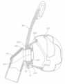
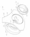
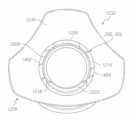
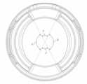
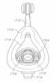
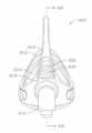
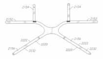
別の態様では、使用されるときに患者の顔面の上に据え付けられる接続ハウジングを備えた、呼吸マスク用のキットが提供される。接続ハウジングは、使用者の顔面と接触するようにクッションハウジングと係合するように構成されたクッション端部分と、クッション端部分と反対側の接続リングとを備える。接続リングは、第1接続ハウジング隆起部分および第2接続ハウジング隆起部分を備え、それらは各々、略弓形であり、クッション端部分から離れるように延在し、各々、使用されるときに使用者によって吐き出される呼気ガスを周囲空気に渡すように構成された、それぞれの弧の少なくとも一部に沿って延在する孔の少なくとも1つの配列を備え、第1接続ハウジング隆起部分および第2接続ハウジング隆起部分は、それらの間に、略弓形の第1接続ハウジング凹状部分と略弓形の第2接続ハウジング凹状部分とを画定し、第1接続ハウジング凹状部分の弧長は、第2接続ハウジング凹状部分の弧長より小さい。キットはまたは、ガス供給部からの吸気ガスを接続ハウジングに渡すように構成された環状ソケットも備える。ソケットは、略弓形の第1ソケット隆起部分と略弓形の第2ソケット隆起部分とを備え、第1ソケット隆起部分の弧長は第2ソケット隆起部分の弧長より小さく、第1ソケット隆起部分および第2ソケット隆起部分は、それらの間に、略弓形の第1ソケットスロットと略弓形の第2ソケットスロットとを画定する。ソケットは、単体構造として接続ハウジングと取外し可能に係合するように構成され、それにより、係合すると、第1ソケット隆起部分は第1接続ハウジング凹状部分と合体し、第2ソケット隆起部分は第2接続ハウジング凹状部分と合体し、第1接続ハウジング隆起部分は、フレーム開口部を通過し、第1ソケットスロットと合体し、第2接続ハウジング隆起部分は、フレーム開口部を通過し、第2ソケットスロットと合体し、かつ、使用されるとき、単体構造を介して、吸気ガスは呼吸マスクに渡され、呼気ガスは呼吸マスクから渡される。 In another aspect, a kit for a respiratory mask is provided that includes a connection housing that is mounted on a patient's face when in use. The connection housing includes a cushion end portion configured to engage the cushion housing to contact the user's face, and a connection ring opposite the cushion end portion. The connecting ring includes a first connecting housing raised portion and a second connecting housing raised portion, each of which is generally arcuate and extends away from the cushion end portion and each is adjusted by the user when in use. A first connection housing raised portion and a second connection housing raised portion comprising at least one array of holes extending along at least a portion of each arc configured to pass exhaled expiratory gases to ambient air. defines therebetween a generally arcuate first connection housing concave portion and a generally arcuate second connection housing concave portion, the arc length of the first connection housing concave portion being equal to the arc of the second connection housing concave portion. less than long. The kit also includes an annular socket configured to pass inspiration gas from the gas supply to the connection housing. The socket includes a first generally arcuate socket raised portion and a second generally arcuate socket raised portion, the arc length of the first socket raised portion being less than the arc length of the second socket raised portion, the first socket raised portion and The second socket raised portions define therebetween a first generally arcuate socket slot and a second generally arcuate socket slot. The socket is configured to removably engage the connection housing as a unitary structure whereby, upon engagement, the first socket raised portion merges with the first connection housing recessed portion and the second socket raised portion merges with the second socket raised portion. two connection housing recessed portions merged, a first connection housing raised portion passing through the frame opening and merged with the first socket slot, a second connection housing raised portion passing through the frame opening and joining the second socket; Inspiratory gas is passed to and from the respiratory mask through the unitary structure when incorporated and used with the slot.
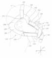
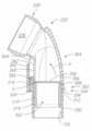
いくつかの構成では、スイベルコネクタは、使用者に吸気ガスを送達するように構成されている。スイベルコネクタは、略管状の第1端部と、第1端部と反対側の第2端部における切頭ボールジョイントとを備え、切頭は、吸気ガスを通過させるように構成されたボールジョイント開口部を画定し、ソケットは、使用されるときに切頭ボールジョイントを受け入れるように構成されている。 In some configurations, the swivel connector is configured to deliver inspiration gas to the user. The swivel connector includes a generally tubular first end and a truncated ball joint at a second end opposite the first end, the truncated ball joint configured to pass inspiratory gases. Defining an opening, the socket is configured to receive a truncated ball joint when in use.
いくつかの構成では、第1ソケットスロットは、第2ソケットスロットの反対側である。 In some configurations, the first socket slot is opposite the second socket slot.
いくつかの構成では、第1接続ハウジング隆起部分は、第2接続ハウジング隆起部分の反対側である。 In some configurations, the first connection housing raised portion is opposite the second connection housing raised portion.
いくつかの構成では、使用されるときに接続ハウジングの上にフレームが据え付けられる。フレームは、フレーム開口部と、フレーム開口部内に据え付けられるソケットとを備える、フレームハウジングを備える。 In some configurations, a frame is mounted over the connection housing when in use. The frame comprises a frame housing comprising a frame opening and a socket mounted within the frame opening.
いくつかの構成では、フレームハウジングはソケットに成形されている。 In some configurations, the frame housing is molded into the socket.
いくつかの構成では、第1接続ハウジング隆起部分および第2接続ハウジング隆起部分は、各々、クッション端部分から最も遠い領域に略L字型端部を備え、第1ソケット隆起部分および第2ソケット隆起部分は、各々、第1ソケットスロットおよび第2ソケットスロットに隣接する領域に略L字型側部を備え、第1接続ハウジング隆起部分および第2接続ハウジング隆起部分の略L字型端部は、第1ソケット隆起部分および第2ソケット隆起部分の略L字型側部と封止するように構成されている。 In some configurations, the first connection housing raised portion and the second connection housing raised portion each include a generally L-shaped end in a region furthest from the cushion end portion, and the first socket raised portion and the second socket raised portion The portions each include generally L-shaped sides in areas adjacent to the first socket slot and the second socket slot, the generally L-shaped ends of the first connection housing raised portion and the second connection housing raised portion: It is configured to seal with the generally L-shaped sides of the first socket raised portion and the second socket raised portion.
いくつかの構成では、第1接続ハウジング隆起部分および第2接続ハウジング隆起部分は、各々、クッション端部分から最も遠い領域に略まっすぐな端部を備え、第1ソケット隆起部分および第2ソケット隆起部分は、各々、第1ソケットスロットおよび第2ソケットスロットに隣接する領域に略まっすぐな側部を備え、第1接続ハウジング隆起部分および第2接続ハウジング隆起部分の略まっすぐな端部は、第1ソケット隆起部分および第2ソケット隆起部分の略まっすぐな側部と封止するように構成されている。 In some configurations, the first connection housing raised portion and the second connection housing raised portion each include a substantially straight edge at the region furthest from the cushion end portion, and the first socket raised portion and the second socket raised portion each have substantially straight sides in regions adjacent the first socket slot and the second socket slot, the substantially straight ends of the first connection housing raised portion and the second connection housing raised portion extending into the first socket It is configured to seal with the substantially straight sides of the raised portion and the second socket raised portion.
別の態様によれば、使用されるときに患者の顔面の上に据え付けられる接続ハウジングを備えた、呼吸マスク用のキットが提供される。接続ハウジングは、使用者の顔面と接触するようにクッションハウジングと係合するように構成されたクッション端部分と、クッション端部分と反対側の接続リングとを備える。接続リングは、第1接続ハウジング隆起部分および第2接続ハウジング隆起部分を備え、それらは各々、略弓形であり、クッション端部分から離れるように延在し、各々、使用されるときに使用者によって吐き出される呼気ガスを周囲空気に渡すように構成された、それぞれの弧の少なくとも一部に沿って延在する孔の少なくとも1つの配列を備え、第1接続ハウジング隆起部分および第2接続ハウジング隆起部分は、それらの間に、略弓形の第1接続ハウジング凹状部分と略弓形の第2接続ハウジング凹状部分とを画定し、第1接続ハウジング凹状部分の弧長は、第2接続ハウジング凹状部分の弧長より小さい。キットはさらに、使用されるときに接続ハウジングの上に据え付けられるフレームを備える。フレームは、略環状のフレーム開口部周縁部を画定するフレーム開口部を備えるフレームハウジングと、ガス供給部からの吸気ガスを接続ハウジングに渡すように構成された環状ソケットとを備え、ソケットは、フレーム開口部と同心配置でフレームハウジング内にあり、略弓形の第1フレーム隆起部分によりかつ略弓形の第2フレーム隆起部分により、フレーム開口部周縁部から間隔を空けて配置され、第1フレーム隆起部分の弧長は第2フレーム隆起部分の弧長より小さく、ソケットとフレーム開口部周縁部との間の空間は、第1フレーム間隙および第2フレーム間隙を含む。フレームは、単体構造として接続ハウジングと取外し可能に係合するように構成され、それにより、係合すると、第1フレーム隆起部分は第1接続ハウジング凹状部分と合体し、第2フレーム隆起部分は第2接続ハウジング凹状部分と合体し、第1接続ハウジング隆起部分は、フレーム開口部を通過し、第1フレーム間隙と合体し、第2接続ハウジング隆起部分は、フレーム開口部を通過し、第2フレーム間隙と合体し、かつ、使用されるとき、単体構造を介して、吸気ガスは呼吸マスクに渡され、呼気ガスは呼吸マスクから渡される。 According to another aspect, a kit for a respiratory mask is provided that includes a connection housing that is mounted on a patient's face when in use. The connection housing includes a cushion end portion configured to engage the cushion housing to contact the user's face, and a connection ring opposite the cushion end portion. The connecting ring includes a first connecting housing raised portion and a second connecting housing raised portion, each of which is generally arcuate and extends away from the cushion end portion and each is adjusted by the user when in use. A first connection housing raised portion and a second connection housing raised portion comprising at least one array of holes extending along at least a portion of each arc configured to pass exhaled expiratory gases to ambient air. defines therebetween a generally arcuate first connection housing concave portion and a generally arcuate second connection housing concave portion, the arc length of the first connection housing concave portion being equal to the arc of the second connection housing concave portion. less than long. The kit further comprises a frame that mounts over the connection housing when used. The frame comprises a frame housing with a frame opening defining a generally annular frame opening perimeter, and an annular socket configured to pass intake gas from the gas supply to the connection housing, the socket comprising: a first generally arcuate frame raised portion within the frame housing concentric with the opening and spaced from the frame opening periphery by a generally arcuate first frame raised portion and by a generally arcuate second frame raised portion; is less than the arc length of the second frame raised portion, and the space between the socket and the frame opening rim includes the first frame gap and the second frame gap. The frame is configured to removably engage the connection housing as a unitary structure such that when engaged, the first frame raised portion merges with the first connection housing recessed portion and the second frame raised portion merges with the second frame raised portion. two connecting housing recessed portions, a first connecting housing raised portion passing through the frame opening and joining with the first frame gap, a second connecting housing raised portion passing through the frame opening and joining the second frame; When merged with the gap and in use, inspiration gases are passed to and from the respiratory mask via the unitary structure.
いくつかの構成では、スイベルコネクタは、使用者に吸気ガスを送達するように構成され、スイベルコネクタは、略管状の第1端部と、第1端部と反対側の第2端部における切頭ボールジョイントとを備え、切頭は、吸気ガスを通過させるように構成されたボールジョイント開口部を画定し、ソケットは、使用されるときに切頭ボールジョイントを受け入れるように構成されている。 In some configurations, the swivel connector is configured to deliver inspiratory gas to a user, the swivel connector having a generally tubular first end and a cutout at a second end opposite the first end. a truncated ball joint, the truncated portion defining a ball joint opening configured to pass intake gases, and the socket configured to receive the truncated ball joint when in use.
いくつかの構成では、第1ソケットスロットは、第2ソケットスロットの反対側である。 In some configurations, the first socket slot is opposite the second socket slot.
いくつかの構成では、第1接続ハウジング隆起部分は、第2接続ハウジング隆起部分の反対側である。 In some configurations, the first connection housing raised portion is opposite the second connection housing raised portion.
いくつかの構成では、フレームハウジングはソケットに成形されている。 In some configurations, the frame housing is molded into the socket.
いくつかの構成では、第1接続ハウジング隆起部分および第2接続ハウジング隆起部分は、各々、クッション端部分から最も遠い領域に略L字型端部を備え、第1ソケット隆起部分および第2ソケット隆起部分は、各々、第1ソケットスロットおよび第2ソケットスロットに隣接する領域に略L字型側部を備え、第1接続ハウジング隆起部分および第2接続ハウジング隆起部分の略L字型端部は、第1ソケット隆起部分および第2ソケット隆起部分の略L字型側部と封止するように構成されている。 In some configurations, the first connection housing raised portion and the second connection housing raised portion each include a generally L-shaped end in a region furthest from the cushion end portion, and the first socket raised portion and the second socket raised portion The portions each include generally L-shaped sides in areas adjacent to the first socket slot and the second socket slot, the generally L-shaped ends of the first connection housing raised portion and the second connection housing raised portion: It is configured to seal with the generally L-shaped sides of the first socket raised portion and the second socket raised portion.
いくつかの構成では、第1接続ハウジング隆起部分および第2接続ハウジング隆起部分は、各々、クッション端部分から最も遠い領域に略まっすぐな端部を備え、第1ソケット隆起部分および第2ソケット隆起部分は、各々、第1ソケットスロットおよび第2ソケットスロットに隣接する領域に略まっすぐな側部を備え、第1接続ハウジング隆起部分および第2接続ハウジング隆起部分の略まっすぐな端部は、第1ソケット隆起部分および第2ソケット隆起部分の略まっすぐな側部と封止するように構成されている。 In some configurations, the first connection housing raised portion and the second connection housing raised portion each include a substantially straight edge at the region furthest from the cushion end portion, and the first socket raised portion and the second socket raised portion each have substantially straight sides in regions adjacent the first socket slot and the second socket slot, the substantially straight ends of the first connection housing raised portion and the second connection housing raised portion extending into the first socket It is configured to seal with the substantially straight sides of the raised portion and the second socket raised portion.
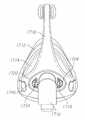
別の態様によれば、呼吸マスク用のキットが提供され、キットは、使用者に吸気ガスを送達するように構成されたスイベルコネクタであって、略管状の第1端部と第1端部と反対側の第2端部における切頭ボールジョイントとを備え、切頭が吸気ガスを通過させるように構成されたボールジョイント開口部を画定する、スイベルコネクタと、使用されるときに使用者の顔面の上に据え付けられる接続ハウジングとを備える。接続ハウジングは、使用時に、スイベルコネクタから吸気ガスを受け取るように、かつ使用者によって吐き出された呼気ガスを受け入れるように構成された接続ハウジング開口部と、使用者の顔面と接触するようにクッションハウジングと係合するように構成された、接続ハウジング開口部とは反対側のクッション端部分とを備える。キットはまた、密閉内部領域を含む中空ソケットも備える。密閉内部領域は、ソケットの第1端部の周囲の概して周方向の接続ハウジング係合領域を備え、接続ハウジング係合領域は、使用されるときに接続ハウジング開口部と係合し、そこから呼気ガスを受け取るように構成されている。接続ハウジング係合領域は、第1径と、ソケットの第1端部と反対側の第2端部の周囲の概して円周方向のボールジョイント係合領域であって、使用されるときにスイベルコネクタの切頭ボールジョイントと係合し、そこから呼気ガスを受け取るように構成され、第1径より小さい第2径を備えるボールジョイント係合領域と、略弓形の第1軸受領域および略弓形の第2軸受領域であって、各々がボールジョイント係合領域から接続ハウジング係合領域に向かって延在し、かつ各々が、使用されるときにスイベルコネクタの切頭ボールジョイントと係合し、それらの間に、略弓形の第1呼気領域と略弓形の第2呼気領域とを画定し、第1呼気領域と第2呼気領域との間の第3径が、第2径より大きくかつ第1径より小さいかまたはそれに等しく、第1呼気領域および第2呼気領域の各々が、呼気ガスを通過させてソケットの外側の周囲空気に渡すように構成された孔の少なくとも1つの配列を備える、第1軸受領域および第2軸受領域とを備える。第1呼気領域の弧長および第2呼気領域の弧長は、第1軸受領域の弧長および第2軸受領域の弧長より大きく、フレームは、使用されるときに、吸気ガスが呼吸マスクに渡され、呼気ガスが、呼吸マスクからソケットを介して周囲空気に渡されるように、構成されている。 According to another aspect, a kit for a respiratory mask is provided, the kit comprising a swivel connector configured to deliver inspiratory gas to a user and comprising a generally tubular first end and a first end. and a truncated ball joint at an opposite second end, the truncated portion defining a ball joint opening configured to pass inspiratory gases; a connection housing for mounting on the face. The connection housing, in use, has a connection housing opening configured to receive inspiration gas from the swivel connector and to receive expiration gas exhaled by the user, and a cushion housing to contact the user's face. and a cushion end portion opposite the connection housing opening configured to engage with. The kit also includes a hollow socket containing a sealed interior region. The sealed interior region includes a generally circumferential connection housing engagement region around the first end of the socket, the connection housing engagement region engaging the connection housing opening when in use and exhaling air therefrom. configured to receive gas. The connection housing engagement area is a generally circumferential ball joint engagement area around a first diameter and a second end opposite the first end of the socket to provide a swivel connector when in use. a ball joint engagement region configured to engage a truncated ball joint of and receive exhaled gas therefrom and comprising a second diameter less than the first diameter; a generally arcuate first bearing region; Two bearing regions, each extending from the ball joint engagement region toward the connection housing engagement region, and each engaging a truncated ball joint of the swivel connector when in use, their defining a first generally arcuate expiratory region and a second generally arcuate expiratory region therebetween, wherein a third diameter between the first expiratory region and the second expiratory region is greater than the second diameter and the first diameter A first, less than or equal to, each of the first expiratory region and the second expiratory region comprising at least one array of holes configured to pass exhaled gas to ambient air outside the socket. A bearing region and a second bearing region are provided. The arc length of the first expiratory region and the arc length of the second expiratory region are greater than the arc length of the first bearing region and the arc length of the second bearing region, and the frame, when in use, directs inspiratory gas to the respiratory mask. and configured such that exhaled gases are passed from the respiratory mask through the socket into the ambient air.
いくつかの構成では、使用されるときに接続ハウジングの上にフレームが据え付けられ、フレームは、略環状のフレーム開口部外周部を画定するフレーム開口部を備えるフレームハウジングを備え、ソケットは、フレーム開口部内に据え付けられる。 In some configurations, a frame is mounted over the connection housing when in use, the frame comprises a frame housing with a frame opening defining a generally annular frame opening perimeter, and the socket is located in the frame opening. Installed inside the department.
いくつかの構成では、フレームハウジングはソケットに成形されている。 In some configurations, the frame housing is molded into the socket.
いくつかの構成では、一続きのスイベルコネクタの内部は、第2端部、切頭ボールジョイント全体を含み、第1端部に向かって延在する切頭ボールジョイントに直接隣接する領域が、連続的な円筒状または連続的なテーパ状の円筒状輪郭を有する。 In some configurations, the interior of the series of swivel connectors includes the second end, the entire truncated ball joint, and the area immediately adjacent the truncated ball joint extending toward the first end is continuous. It has a uniform cylindrical or continuously tapering cylindrical profile.
いくつかの構成では、切頭ボールジョイントの内側輪郭は、概して、切頭ボールジョイントの対応する外側輪郭をたどる。 In some configurations, the inner contour of the truncated ball joint generally follows the corresponding outer contour of the truncated ball joint.
いくつかの構成では、スイベルコネクタおよびソケットは、スイベルコネクタの切頭ボールジョイントが、ソケットのボールジョイント係合領域内で任意の方向に最大限回転するとき、スイベルコネクタの第2端部がソケット内でボールジョイント係合領域の上に完全に張り出すように、構成されている。 In some configurations, the swivel connector and socket are such that when the truncated ball joint of the swivel connector is fully rotated in any direction within the ball joint engagement area of the socket, the second end of the swivel connector is positioned within the socket. is designed to overhang completely over the ball joint engagement area.
いくつかの構成では、スイベルコネクタおよびソケットは、スイベルコネクタの切頭ボールジョイントが、ソケットのボールジョイント係合領域内で中立位置にあるとき、スイベルコネクタの第2端部がソケット内で第1軸受領域および第2軸受領域の上に完全に張り出すように、構成されている。 In some configurations, the swivel connector and socket are configured so that the second end of the swivel connector engages the first bearing within the socket when the truncated ball joint of the swivel connector is in a neutral position within the ball joint engagement area of the socket. It is configured to completely overhang the area and the second bearing area.
いくつかの構成では、周囲空気に面するボールジョイント係合領域の外側輪郭は、連続勾配を有する。 In some configurations, the outer contour of the ball joint engagement area facing the ambient air has a continuous slope.
いくつかの構成では、周囲空気に面するボールジョイント係合領域の外側輪郭は、第2端部からある箇所までの距離の第1勾配と、第1端部に向かって延在する上記箇所からのボールジョイント係合領域の残りの長さの、第1勾配とは異なる第2勾配とを有する。 In some configurations, the outer contour of the ball joint engagement area facing the ambient air has a first slope of the distance from the second end to a point and from said point extending towards the first end. and a second slope different from the first slope of the remaining length of the ball joint engagement region.
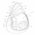
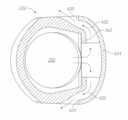
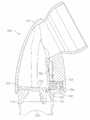
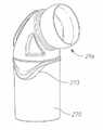
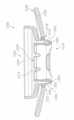
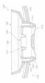
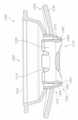
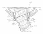
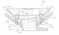
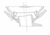
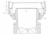
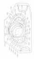
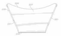
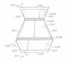
別の態様によれば、クッションハウジングと、開口部と開口部と画定する内壁とを有するフレームと、ガス供給部から吸気ガスを提供するように構成されたスイベルエルボであって、ボールジョイントを有するスイベルエルボと、フレームの開口部内に配置された環状挿入体とを備える呼吸マスクアセンブリが提供される。環状挿入体は、カバー部分と、使用されるときに使用者に向かう方向にカバー部分の周縁部から離れるように延在するカラー部分と、カバー部分およびカラー部分によって画定される内部領域であって、吸気ガスをガス供給部から接続ハウジングに渡し、使用者によって吐き出される呼気ガスを受け取るように構成された内部領域と、カバー部分を通って延在しかつボールジョイントと係合するように構成されたスイベルエルボソケットと、カバー部分の上に配置されかつスイベルエルボソケットの横方向側部に位置する排気領域であって、使用されるときに内部領域によって受け取られる呼気ガスを周囲空気に渡すようにカバー部分を通って延在する排気孔を有する排気領域とを備える。カラー部分は、排気挿入体が開口部内に配置されかつフレームに接続されるように開口部の内壁と係合し、カラー部分は、クッションハウジングが排気挿入体を介してフレームに取り付けられるようにクッションハウジングと係合する。 According to another aspect, a frame having a cushion housing, an opening and an inner wall defining the opening, and a swivel elbow configured to provide intake gas from a gas supply, the elbow having a ball joint. A respiratory mask assembly is provided that includes a swivel elbow and an annular insert positioned within an opening in the frame. The annular insert comprises a cover portion, a collar portion extending away from a peripheral edge of the cover portion in a direction toward the user when in use, and an interior region defined by the cover portion and the collar portion. an interior region configured to pass inspiratory gas from the gas supply to the connection housing and receive expiratory gas exhaled by the user; and a cover portion extending through the cover portion and configured to engage the ball joint. and an exhaust area positioned over the cover portion and laterally laterally of the swivel elbow socket to pass exhaled gases received by the inner area to ambient air when in use. a vent region having vent holes extending through the cover portion. The collar portion engages the inner wall of the opening such that the exhaust insert is positioned within the opening and is connected to the frame, and the collar portion engages the cushion housing such that the cushion housing is attached to the frame through the exhaust insert. engage the housing.
いくつかの構成では、スイベルエルボソケットは、ボールジョイントと係合するように構成された横方向ソケット側壁をさらに備え、横方向ソケット側壁は、カバー部分の内面から離れて環状挿入体の内部領域内に延在している。横方向ソケット側壁の中心部分は、横方向ソケット側壁の端部分より環状挿入体の内部領域内により大きい距離延在している。 In some configurations, the swivel elbow socket further comprises a lateral socket sidewall configured to engage the ball joint, the lateral socket sidewall extending away from the inner surface of the cover portion and within the inner region of the annular insert. extends to The central portion of the transverse socket sidewall extends a greater distance into the interior region of the annular insert than the end portions of the transverse socket sidewall.
いくつかの構成では、スイベルエルボソケットは、ボールジョイントの下方部分と係合するように構成された下部ソケット側壁をさらに備え、下部ソケット側壁は、カバー部分の内面から離れて環状挿入体の内部領域内に延在している。下部ソケット側壁の端部分および横方向側壁の端部分は、環状挿入体の内部領域内に等しい距離延在している。 In some configurations, the swivel elbow socket further comprises a lower socket sidewall configured to engage the lower portion of the ball joint, the lower socket sidewall extending away from the inner surface of the cover portion to the inner region of the annular insert. extends inside. The end portion of the lower socket sidewall and the end portion of the lateral sidewall extend an equal distance into the interior region of the annular insert.
いくつかの構成では、スイベルエルボソケットは、ボールジョイントの上方部分と係合するように構成された上部ソケット側壁をさらに備え、上部ソケット側壁は、カバー部分の内面から離れて環状挿入体の内部領域内に延在している。上部ソケット側壁の端部分および横方向側壁の端部分は、環状挿入体の内部領域内に等しい距離延在している。 In some configurations, the swivel elbow socket further comprises an upper socket sidewall configured to engage the upper portion of the ball joint, the upper socket sidewall extending away from the inner surface of the cover portion to the inner region of the annular insert. extends inside. The end portion of the upper socket sidewall and the end portion of the lateral sidewall extend an equal distance into the interior region of the annular insert.
いくつかの構成では、横方向側壁の端部分は、カラー部分の内面と一体的に成形されている。 In some configurations, the end portions of the lateral sidewalls are integrally molded with the inner surface of the collar portion.
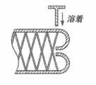
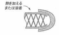
いくつかの構成では、カラー部分は、溶着領域に沿ってフレームの開口部の内壁に溶接される。 In some configurations, the collar portion is welded to the inner wall of the frame opening along the weld area.
いくつかの構成では、各排気領域が、異なる通風方向に吐出ガスを吐き出す(expirate)。 In some configurations, each exhaust region expires exhaled gas in a different draft direction.
いくつかの構成では、排気孔は平面形状を有する。 In some configurations, the vent has a planar shape.
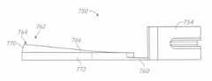
いくつかの構成では、環状挿入体は、ボールジョイントの底部分とカラー部分との間に配置された凹状部分をさらに備え、凹状部分は、内部領域内の蓄積汚物を除去するために浅い使用者アクセス可能な空洞を提供するように構成されている。 In some configurations, the annular insert further comprises a recessed portion disposed between the bottom portion of the ball joint and the collar portion, the recessed portion having a shallow user depth for removing accumulated dirt within the interior region. configured to provide an accessible cavity;
いくつかの構成では、ボールジョイントは、ボールジョイントの底部分に凹状部分と係合する切取領域を有する。 In some configurations, the ball joint has a cutout area in the bottom portion of the ball joint that engages the recessed portion.
別の態様によれば、フレームと、クッションハウジングと、ガス供給部から吸気ガスを提供するように構成されたスイベルエルボであって、ボールジョイントを有するスイベルエルボと、フレームに取り付けられた環状ソケットとを備える、呼吸マスクアセンブリが提供される。環状ソケットは、カバー部分と、使用されるときに使用者に向かう方向にカバー部分の内面から離れるように延在するカラー部分であって、クッションハウジングがフレームに取り付けられるようにクッションハウジングに接続されたカラー部分と、カバー部分およびカラー部分によって画定された内部領域であって、ガス供給部からの吸気ガスを接続ハウジングに渡し、使用者によって吐き出される呼気ガスを受け取るように構成された内部領域と、カバー部分を通って延在しかつボールジョイントと係合するように構成されたスイベルエルボソケットであって、ボールジョイントと係合するように構成された横方向ソケット側壁を備え、横方向ソケット側壁が、カバー部分の内面から離れて環状ソケットの内部領域内に延在する、スイベルエルボソケットとを備え、横方向ソケット側壁の中心部分は、横方向ソケット側壁の端部分より環状ソケットの内部領域内に大きい距離延在している。 According to another aspect, a frame, a cushion housing, and a swivel elbow configured to provide intake gas from a gas supply, the swivel elbow having a ball joint and an annular socket attached to the frame. A respiratory mask assembly is provided comprising: The annular socket is a cover portion and a collar portion extending away from the inner surface of the cover portion in a direction toward the user when in use and connected to the cushion housing such that the cushion housing is attached to the frame. and an interior region defined by the cover portion and the collar portion, the interior region configured to pass inspiration gas from the gas supply to the connection housing and receive expiration gas exhaled by the user. a swivel elbow socket extending through the cover portion and configured to engage the ball joint, the lateral socket sidewall configured to engage the ball joint; extends into the inner region of the annular socket away from the inner surface of the cover portion, the central portion of the lateral socket sidewall being within the inner region of the annular socket than the end portion of the lateral socket sidewall. It extends a great distance.
いくつかの構成では、スイベルエルボソケットは、ボールジョイントの下方部分と係合するように構成された下部ソケット側壁をさらに備え、下部ソケット側壁は、カバー部分の内面から離れて環状ソケットの内部領域内に延在している。下部ソケット側壁の端部分および横方向側壁の端部分は、環状ソケットの内部領域内に等しい距離延在している。 In some configurations, the swivel elbow socket further comprises a lower socket sidewall configured to engage the lower portion of the ball joint, the lower socket sidewall extending away from the inner surface of the cover portion and within the inner region of the annular socket. extends to The end portion of the lower socket sidewall and the end portion of the lateral sidewall extend an equal distance into the interior region of the annular socket.
いくつかの構成では、スイベルエルボソケットは、ボールジョイントの上方部分と係合するように構成された上部ソケット側壁をさらに備え、上部ソケット側壁は、カバー部分の内面から離れて環状ソケットの内部領域内に延在している。上部ソケット側壁の端部分および横方向側壁の端部分は、環状ソケットの内部領域内に等しい距離延在している。 In some configurations, the swivel elbow socket further comprises an upper socket sidewall configured to engage the upper portion of the ball joint, the upper socket sidewall extending away from the inner surface of the cover portion and within the inner region of the annular socket. extends to The end portion of the upper socket sidewall and the end portion of the lateral sidewall extend an equal distance into the interior region of the annular socket.
いくつかの構成では、横方向側壁の端部分は、カラー部分の内面と一体的に成形されている。 In some configurations, the end portions of the lateral sidewalls are integrally molded with the inner surface of the collar portion.
いくつかの構成では、凹状部分がボールジョイントの底部分とカラー部分との間に配置されている。凹状部分は、内部領域内の蓄積汚物を除去するために浅い使用者アクセス可能な空洞を提供するように構成されている。 In some configurations, the recessed portion is located between the bottom portion of the ball joint and the collar portion. The recessed portion is configured to provide a shallow, user-accessible cavity for removing accumulated dirt within the interior region.
いくつかの構成では、環状ソケットは、ボールジョイントの底部分に凹状部分と係合する切取領域を有する。 In some configurations, the annular socket has a cutout area in the bottom portion of the ball joint that engages the recessed portion.
いくつかの構成では、環状ソケットは、フレームに挿入されかつ取外し可能に締結されるように構成されている。 In some configurations, the annular socket is configured to be inserted into and removably fastened to the frame.
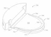
いくつかの構成では、環状ソケットは、使用されるときに、内部領域によって受け取られる呼気ガスを周囲空気に渡すように、カバー部分を通って延在する排気孔を有する少なくとも1つの排気領域をさらに備える。 In some configurations, the annular socket further includes at least one exhaust region having an exhaust hole extending through the cover portion to pass exhaled gases received by the interior region to ambient air when in use. Prepare.
いくつかの構成では、各排気領域は、異なる通風方向に吐出ガスを吐き出す。 In some configurations, each exhaust region discharges exhaled gas in a different draft direction.
いくつかの構成では、排気孔は平面形状を有する。 In some configurations, the vent has a planar shape.
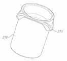
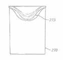
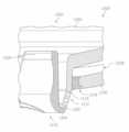
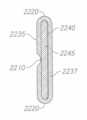
別の態様によれば、フレームと、クッションと、第1端部に取り付けられたクッションを有する接続ハウジングと、第1端部と反対側の接続ハウジングの第2端部に取り付けられた接続リングとを備える、呼吸マスクアセンブリが提供される。接続リングは、接続リングを通って延在する中心開口部と、接続ハウジングから離れる方向に延在しかつ中心開口部の一部を画定する少なくとも1つの隆起部分であって、孔の少なくとも1つの配列を備える少なくとも1つの隆起部分とを備える。呼吸マスクアセンブリは、フレームに取り付けられた環状ソケットを更に備える。環状ソケットは、フレームおよびガス供給部を通って延在する管状中心部分と、少なくとも1つのスロットとを備え、少なくとも1つのスロットは、環状ソケットを通って延在し、かつ、少なくとも1つのスロットの一部が管状中心部分の外面によって画定されるように、管状中心部分に隣接して配置されている。接続リングは、管状中心部分の外面の上に取外し可能に配置されるように構成され、それにより、管状中心部分は接続リングの中心開口部を通って延在し、少なくとも1つの隆起部分は、少なくとも1つのスロット内に挿入されるように構成され、それにより、少なくとも1つの隆起部分は環状ソケットを通って延在し、管状ソケットの内面は、ガス供給部からの吸気ガスのためにクッションへの流路を画定し、管状ソケットの外面は、呼気ガスが空気中に排気されるために、クッションから孔の少なくとも1つの配列への流路を画定している。 According to another aspect, a frame, a cushion, a connection housing having the cushion attached to a first end, and a connection ring attached to a second end of the connection housing opposite the first end. A respiratory mask assembly is provided comprising: The connecting ring has a central opening extending through the connecting ring and at least one raised portion extending away from the connection housing and defining a portion of the central opening, and at least one of the holes. and at least one raised portion comprising an array. The respiratory mask assembly further includes an annular socket attached to the frame. The annular socket comprises a tubular central portion extending through the frame and the gas supply, and at least one slot, the at least one slot extending through the annular socket and the at least one slot extending through the annular socket. It is positioned adjacent to the tubular central portion such that a portion is defined by the outer surface of the tubular central portion. The connecting ring is configured to be removably disposed over the outer surface of the tubular central portion such that the tubular central portion extends through the central opening of the connecting ring and the at least one raised portion comprises: configured to be inserted into the at least one slot such that the at least one raised portion extends through the annular socket and the inner surface of the tubular socket faces the cushion for inspiratory gas from the gas supply; and the outer surface of the tubular socket defines a flow path from the cushion to the at least one array of holes for expiratory gases to be exhausted into the air.
いくつかの構成では、スイベルコネクタは、使用者に吸気ガスを送達するように構成され、スイベルコネクタは、略管状の第1端部と、第1端部と反対側の第2端部における切頭ボールジョイントとを備え、切頭は、吸気ガスを通過させるように構成されたボールジョイント開口部を画定し、管状中心部分は、使用されるときに切頭ボールジョイントを受け入れるように構成されている。 In some configurations, the swivel connector is configured to deliver inspiratory gas to a user, the swivel connector having a generally tubular first end and a cutout at a second end opposite the first end. a truncated ball joint, the truncated portion defining a ball joint opening configured to pass inspiratory gases, and the tubular central portion configured to receive the truncated ball joint when in use. there is
いくつかの構成では、少なくとも1つのスロットは、第1ソケットスロットと、第1ソケットスロットとは反対側の第2ソケットスロットとをさらに備え、少なくとも1つの隆起部分は、第1隆起部分と第1隆起部分とは反対側の第2隆起部分とをさらに備える。 In some configurations, the at least one slot further comprises a first socket slot and a second socket slot opposite the first socket slot, and the at least one raised portion comprises the first raised portion and the first socket slot. A second raised portion opposite the raised portion.
いくつかの構成では、環状ソケットおよびフレームは一体的に形成される。 In some configurations, the annular socket and frame are integrally formed.
いくつかの構成では、環状ソケットは、フレームに挿入されかつ取外し可能に締結されるように構成されている。 In some configurations, the annular socket is configured to be inserted into and removably fastened to the frame.
いくつかの構成では、環状ソケットは、クッションと反対側の管状中心部分の端部に配置されたL字型端部をさらに備え、接続リングは、クッションと反対側の少なくとも1つの隆起部分の端部に配置されたL字型側部をさらに備え、L字型端部はL字型側部と係合して、環状ソケットと接続リングとの間にシールを形成する。 In some configurations, the annular socket further comprises an L-shaped end located at the end of the tubular central portion opposite the cushion, and the connecting ring is located at the end of the at least one raised portion opposite the cushion. It further comprises an L-shaped side disposed on the portion, the L-shaped end engaging the L-shaped side to form a seal between the annular socket and the connecting ring.
いくつかの構成では、環状ソケットは、クッションと反対側の管状中心部分の端部に配置されたまっすぐな端部をさらに備え、接続リングは、クッションと反対側の少なくとも1つの隆起部分の端部に配置されたまっすぐな側部をさらに備え、まっすぐな端部はまっすぐな側部と係合して、環状ソケットと接続リングとの間にシールを形成する。 In some configurations, the annular socket further comprises a straight end located at the end of the tubular central portion opposite the cushion and the connecting ring is located at the end of the at least one raised portion opposite the cushion. and the straight end engages the straight side to form a seal between the annular socket and the connecting ring.
いくつかの構成では、呼吸マスクアセンブリは、フレームと、クッションと、第2端部と反対側の第1端部においてクッションに取り付けられた接続ハウジングと、ガス供給部から吸気ガスを提供するように構成され、切頭ボールジョイントを有するスイベルコネクタと、フレームにかつ接続ハウジングの第2端部に取り付けられた環状ソケットとを備える。環状ソケットは、接続ハウジングと係合するように構成された接続ハウジング係合領域と、スイベルコネクタの切頭ボールジョイントと係合するように構成されたボールジョイント係合領域と、接続ハウジング係合領域とボールジョイント係合領域との間に配置された少なくとも1つの排気領域であって、少なくとも1つの排気領域を通って延在し、かつ呼気ガスを通過させて環状ソケットの外側の周囲空気に渡すように構成された、孔の少なくとも1つの配列を有する少なくとも1つの排気領域とを備える。切頭ボールジョイントの内面が、ガス供給部からの吸気ガスのためにクッションへの流路を画定し、切頭ボールジョイントの外面が、呼気ガスが空気中に排気されるためにクッションから孔の少なくとも1つの配列への流路を画定する。 In some configurations, the respiratory mask assembly includes a frame, a cushion, a connecting housing attached to the cushion at a first end opposite the second end, and a gas supply to provide inspiratory gas. a swivel connector having a truncated ball joint; and an annular socket attached to the frame and to the second end of the connection housing. The annular socket has a connection housing engagement area configured to engage the connection housing, a ball joint engagement area configured to engage a truncated ball joint of the swivel connector, and a connection housing engagement area. and the ball joint engagement region, extending through the at least one exhaust region and allowing exhaled gases to pass to ambient air outside the annular socket. and at least one exhaust region having at least one array of holes configured to. The inner surface of the truncated ball joint defines a flow path to the cushion for inspiratory gas from the gas supply, and the outer surface of the truncated ball joint defines a hole from the cushion for exhaled gas to be exhausted into the air. A flow path to at least one array is defined.
いくつかの構成では、環状ソケットおよびフレームは一体的に形成される。 In some configurations, the annular socket and frame are integrally formed.
いくつかの構成では、環状ソケットは、フレームに挿入されかつ取外し可能に締結されるように構成されている。 In some configurations, the annular socket is configured to be inserted into and removably fastened to the frame.
いくつかの構成では、スイベルコネクタおよび環状ソケットは、切頭ボールジョイントが、ボールジョイント係合領域内で任意の方向に最大限回転するとき、切頭ボールジョイントの開放端部が環状ソケット内でボールジョイント係合領域の上に完全に張り出すように、構成されている。 In some configurations, the swivel connector and annular socket are such that the open end of the truncated ball joint is balled within the annular socket when the truncated ball joint is fully rotated in any direction within the ball joint engagement area. It is configured to overhang completely over the joint engagement area.
いくつかの構成では、スイベルコネクタおよび環状ソケットは、切頭ボールジョイントが、環状ソケットのボールジョイント係合領域内で中立位置にあるとき、切頭ボールジョイントの開放端部が環状ソケット内でボールジョイント係合領域の上に完全に張り出すように、構成されている。 In some configurations, the swivel connector and annular socket are configured so that the open end of the truncated ball joint engages the ball joint within the annular socket when the truncated ball joint is in a neutral position within the ball joint engagement area of the annular socket. It is configured to overhang completely above the engagement area.
いくつかの構成では、環状ソケットは、切頭ボールジョイントの両側に係合する第1軸受領域および第2軸受領域をさらに備え、第1軸受領域および第2軸受領域は、クッションに向かう方向にボールジョイント係合領域から延在し、それにより、第1軸受領域と第2軸受領域との間に凹状領域が形成されている。 In some configurations, the annular socket further comprises a first bearing area and a second bearing area engaging opposite sides of the truncated ball joint, the first bearing area and the second bearing area facing the ball in a direction toward the cushion. A recessed area extends from the joint engagement area thereby forming a recessed area between the first bearing area and the second bearing area.
いくつかの構成では、排気領域は凹状領域内に配置されている。 In some configurations, the exhaust area is located within the recessed area.
いくつかの構成では、排気領域への流路は、第1軸受領域および第2軸受領域と、環状ソケットの内面と、切頭ボールジョイントの外面とによって画定されている。 In some configurations, the flow path to the exhaust region is defined by the first and second bearing regions, the inner surface of the annular socket, and the outer surface of the truncated ball joint.
別の態様によれば、接続リングおよびフレームを含むクッションを備える呼吸マスクアセンブリが提供される。接続リングは、開口部と、クッションから離れる方向に延在しかつ開口部の一部を画定し、少なくとも1つの排気孔を備える少なくとも1つの隆起部分とを備える。フレームは、フレームを通って延在しかつガス供給部から吸気ガスを受け取るように構成された中心導管と、フレームを通って延在する少なくとも1つのスロットと、フレームの患者に面する側から延在しかつ中心導管および少なくとも1つのスロットを包囲する環状カラーとを備える。接続リングは、環状カラーに取外し可能に取付可能であるように構成され、少なくとも1つの隆起部分は、少なくとも1つのスロット内に延在するように構成されている。取り付けられると、少なくとも1つの隆起部分および中心導管は、少なくとも一部には、呼気ガスが空気に排気されるためのクッションから少なくとも1つの排気孔への流路を画定する。 According to another aspect, a respiratory mask assembly is provided that includes a cushion that includes connecting rings and a frame. The connecting ring includes an opening and at least one raised portion extending away from the cushion and defining a portion of the opening and including at least one vent hole. The frame includes a central conduit extending through the frame and configured to receive inspired gas from the gas supply, at least one slot extending through the frame, and extending from the patient-facing side of the frame. and an annular collar surrounding the central conduit and the at least one slot. The connecting ring is configured to be removably attachable to the annular collar and the at least one raised portion is configured to extend into the at least one slot. When attached, the at least one raised portion and the central conduit at least partially define a flow path from the cushion to the at least one vent for expiratory gases to be vented to the air.
いくつかの構成では、少なくとも1つのスロットは中心導管に隣接して配置されている。 In some configurations, at least one slot is positioned adjacent to the central conduit.
いくつかの構成では、クッションは、クッションと接続リングとの間に配置された接続ハウジングを備え、それにより、クッションは第1端部に取り付けられ、クッションリングは第2端部に取り付けられている。 In some configurations, the cushion includes a connection housing positioned between the cushion and the connection ring, whereby the cushion is attached to the first end and the cushion ring is attached to the second end. .
いくつかの構成では、少なくとも1つのスロットの一部は、中心導管の外面によって画定されている。 In some configurations, a portion of the at least one slot is defined by the outer surface of the central conduit.
いくつかの構成では、取り付けられると、中心導管は、少なくとも一部には、ガス供給部からの吸気ガスのためのクッションへの流路を画定する。 In some configurations, when installed, the central conduit at least partially defines a flow path for inspiration gas from the gas supply to the cushion.
いくつかの構成では、使用者に吸気ガスを送達するように構成されたスイベルコネクタをさらに備え、スイベルコネクタは、略管状の第1端部と、第1端部と反対側の第2端部における切頭ボールジョイントとを備え、切頭は、吸気ガスを通過させるように構成されたボールジョイント開口部を画定し、中心導管は、使用されるときに、切頭ボールジョイントを受け入れるように構成されている。 Some configurations further comprise a swivel connector configured to deliver inspiration gas to a user, the swivel connector having a generally tubular first end and a second end opposite the first end. a truncated ball joint in the truncated ball joint, the truncated defining a ball joint opening configured to pass inspiratory gases, and the central conduit configured to receive the truncated ball joint when in use. It is
いくつかの構成では、少なくとも1つのスロットは、第1ソケットスロットと第1ソケットスロットと反対側の第2ソケットスロットとをさらに備え、少なくとも隆起部分は、第1隆起部分と第1隆起部分とは反対側の第2隆起部分とをさらに備える。 In some configurations, the at least one slot further comprises a first socket slot and a second socket slot opposite the first socket slot, and the at least raised portion is different from the first raised portion and the first raised portion. and a second raised portion on the opposite side.
いくつかの構成では、環状カラーおよびフレームは一体的に形成されている。 In some configurations, the annular collar and frame are integrally formed.
いくつかの構成では、環状カラーは、フレームに挿入されかつ取外し可能に締結されるように構成されている。 In some configurations, the annular collar is configured to be inserted and removably fastened to the frame.
いくつかの構成では、中心導管は、クッションと反対側の管状中心部分の端部に配置されたL字型端部をさらに備える。接続リングは、クッションと反対側の少なくとも1つの隆起部分の端部に配置されたL字型側部をさらに備える。L字型端部はL字型側部と係合して、中心導管と接続リングとの間にシールを形成する。 In some configurations, the central conduit further comprises an L-shaped end located at the end of the tubular central portion opposite the cushion. The connecting ring further comprises an L-shaped side located at the end of the at least one raised portion opposite the cushion. The L-shaped ends engage the L-shaped sides to form a seal between the central conduit and the connecting ring.
いくつかの構成では、中心導管は、クッションと反対側の端部に配置されたまっすぐな端部をさらに備え、接続リングは、クッションと反対側の少なくとも1つの隆起部分の端部に配置されたまっすぐな側部をさらに備え、まっすぐな端部はまっすぐな側部と係合して、中心と接続リングとの間にシールを形成する。 In some configurations, the central conduit further comprises a straight end located at the end opposite the cushion and the connecting ring located at the end of the at least one raised portion opposite the cushion. A straight side is further provided and the straight end engages the straight side to form a seal between the center and the connecting ring.
別の態様によれば、フレームと、クッションと、第2端部と反対側の第1端部においてクッションに取り付けられた接続ハウジングと、ガス供給部から吸気ガスを提供するように構成され、切頭ボールジョイントを有するスイベルコネクタと、フレームにかつ接続ハウジングの第2端部に取り付けられた環状ソケットとを備える、呼吸マスクアセンブリが提供される。環状ソケットは、接続ハウジングと係合するように構成された接続ハウジング係合領域と、スイベルコネクタの切頭ボールジョイントと係合するように構成されたボールジョイント係合領域と、接続ハウジング係合領域とボールジョイント係合領域との間に配置された少なくとも1つの排気領域であって、少なくとも1つの排気領域を通って延在し、かつ呼気ガスを通過させて環状ソケットの外側の周囲空気に渡すように構成された、孔の少なくとも1つの配列を有する少なくとも1つの排気領域とを備える。切頭ボールジョイントの内面が、ガス供給部からの呼気ガスのためにクッションへの流路を画定している。切頭ボールジョイントの外面が、呼気ガスが空気中に排気されるためにクッションから孔の少なくとも1つの配列への流路を画定している。 According to another aspect, a frame, a cushion, a connection housing attached to the cushion at a first end opposite the second end, and configured to provide inspiratory gas from a gas supply and a switch. A respiratory mask assembly is provided that includes a swivel connector having a head ball joint and an annular socket attached to the frame and to the second end of the connection housing. The annular socket has a connection housing engagement area configured to engage the connection housing, a ball joint engagement area configured to engage a truncated ball joint of the swivel connector, and a connection housing engagement area. and the ball joint engagement region, extending through the at least one exhaust region and allowing exhaled gases to pass to ambient air outside the annular socket. and at least one exhaust region having at least one array of holes configured to. An inner surface of the truncated ball joint defines a flow path to the cushion for exhaled gas from the gas supply. An outer surface of the truncated ball joint defines a flow path from the cushion to the at least one array of holes for expiratory gases to be exhausted into the air.
いくつかの構成では、環状ソケットおよびフレームは一体的に形成されている。 In some configurations, the annular socket and frame are integrally formed.
いくつかの構成では、環状ソケットは、フレームに挿入されかつ取外し可能に締結されるように構成されている。 In some configurations, the annular socket is configured to be inserted into and removably fastened to the frame.
いくつかの構成では、スイベルコネクタおよび環状ソケットは、切頭ボールジョイントが、ボールジョイント係合領域内で任意の方向に最大限回転するとき、切頭ボールジョイントの開放端部が環状ソケット内でボールジョイント係合領域の上に完全に張り出すように、構成されている。 In some configurations, the swivel connector and annular socket are such that the open end of the truncated ball joint is balled within the annular socket when the truncated ball joint is fully rotated in any direction within the ball joint engagement area. It is configured to overhang completely over the joint engagement area.
いくつかの構成では、スイベルコネクタおよび環状ソケットは、切頭ボールジョイントが、環状ソケットのボールジョイント係合領域内で中立位置にあるとき、切頭ボールの開放端部が環状ソケット内でボールジョイント係合領域の上に完全に張り出すように、構成されている。 In some configurations, the swivel connector and annular socket are such that the open end of the truncated ball engages the ball joint within the annular socket when the truncated ball joint is in a neutral position within the ball joint engagement area of the annular socket. It is configured so that it overhangs completely above the joint area.
いくつかの構成では、環状ソケットは、切頭ボールジョイントの両側に係合する第1軸受領域および第2軸受領域をさらに備え、第1軸受領域および第2軸受領域は、クッションに向かう方向にボールジョイント係合領域から延在し、それにより、第1軸受領域と第2軸受領域との間に凹状領域が形成されている。 In some configurations, the annular socket further comprises a first bearing area and a second bearing area engaging opposite sides of the truncated ball joint, the first bearing area and the second bearing area facing the ball in a direction toward the cushion. A recessed area extends from the joint engagement area thereby forming a recessed area between the first bearing area and the second bearing area.
いくつかの構成では、排気領域は凹状領域内に配置されている。 In some configurations, the exhaust area is located within the recessed area.
いくつかの構成では、排気領域への流路は、第1軸受領域および第2軸受領域と、環状ソケットの内面と、切頭ボールジョイントの外面とによって画定されている。 In some configurations, the flow path to the exhaust region is defined by the first and second bearing regions, the inner surface of the annular socket, and the outer surface of the truncated ball joint.
別の態様によれば、フレームと、クッションと、ガス供給部から吸気ガスを受け取るように構成された第1端部と第2端部とを有するスイベルコネクタと、フレームに取り付けられた環状ソケットとを備える、呼吸マスクアセンブリが提供される。環状ソケットは、クッションと係合するように構成されたクッション係合領域と、スイベルコネクタの第2端部と係合するように構成され、かつ第1軸受領域、第2軸受領域、および第1軸受領域と第2軸受領域との間に形成された凹状領域を備えるスイベルコネクタ係合領域と、クッション係合領域とスイベルコネクタ係合領域との間に配置された少なくとも1つの排気領域とを備え、少なくとも1つの排気領域は凹状領域に隣接する。 According to another aspect, a frame, a cushion, a swivel connector having first and second ends configured to receive inspired gas from a gas supply, and an annular socket attached to the frame. A respiratory mask assembly is provided comprising: The annular socket is configured to engage a cushion engaging region configured to engage the cushion, a second end of the swivel connector, and includes a first bearing region, a second bearing region, and a first bearing region. a swivel connector engagement region comprising a recessed region formed between the bearing region and the second bearing region; and at least one exhaust region positioned between the cushion engagement region and the swivel connector engagement region. , the at least one exhaust region adjoins the recessed region.
別の態様によれば、フレームと、クッションと、ガス供給部から吸気ガスを受け取るように構成された第1端部と第2端部とを有するスイベルコネクタと、フレームに取り付けられた環状ソケットとを備える、呼吸マスクアセンブリが提供される。環状ソケットは、クッションと係合するように構成されたクッション係合領域と、スイベルコネクタの第2端部と係合するように構成され、かつ第1軸受領域、第2軸受領域、および第1軸受領域と第2軸受領域との間に形成された凹状領域を備えるスイベルコネクタ係合領域と、クッション係合領域とスイベルコネクタ係合領域との間に配置された少なくとも1つの排気領域とを備え、少なくとも1つの排気領域は凹状領域に隣接する。 According to another aspect, a frame, a cushion, a swivel connector having first and second ends configured to receive inspired gas from a gas supply, and an annular socket attached to the frame. A respiratory mask assembly is provided comprising: The annular socket is configured to engage a cushion engaging region configured to engage the cushion, a second end of the swivel connector, and includes a first bearing region, a second bearing region, and a first bearing region. a swivel connector engagement region comprising a recessed region formed between the bearing region and the second bearing region; and at least one exhaust region positioned between the cushion engagement region and the swivel connector engagement region. , the at least one exhaust region adjoins the recessed region.
いくつかの構成では、スイベルコネクタの内面は、ガス供給部からの吸気ガスのためのクッションへの吸気流路を画定する。 In some configurations, the inner surface of the swivel connector defines an inspiratory flow path to the cushion for inspiratory gas from the gas supply.
いくつかの構成では、スイベルコネクタは切頭ボールジョイントである。 In some configurations the swivel connector is a truncated ball joint.
いくつかの構成では、スイベルコネクタの外面は、少なくとも一部には、呼気ガスが空気中に排気されるためのクッションから孔の少なくとも1つの配列への呼気流路を画定している。 In some configurations, the outer surface of the swivel connector at least partially defines an exhalation flow path from the cushion to the at least one array of holes for expiratory gases to be exhausted into the air.
いくつかの構成では、少なくとも1つの排気領域は、少なくとも1つの排気領域を通って延在し、かつ呼気ガスを通過させて環状ソケットの外側の周囲空気に渡すように構成された、孔の少なくとも1つの配列をさらに備える。 In some configurations, the at least one exhaust region extends through the at least one exhaust region and is configured to pass exhaled gas to ambient air outside the annular socket. It further comprises an array.
いくつかの構成では、環状ソケットおよびフレームは一体的に形成されている。 In some configurations, the annular socket and frame are integrally formed.
いくつかの構成では、環状ソケットは、フレームに挿入されかつ取外し可能に締結されるように構成されている。 In some configurations, the annular socket is configured to be inserted into and removably fastened to the frame.
いくつかの構成では、スイベルコネクタおよび環状ソケットは、切頭ボールジョイントが、ボールジョイント係合領域内で任意の方向に最大限回転するとき、切頭ボールジョイントの開放端部が環状ソケット内でボールジョイント係合領域の上に完全に張り出すように、構成されている。 In some configurations, the swivel connector and annular socket are such that the open end of the truncated ball joint is balled within the annular socket when the truncated ball joint is fully rotated in any direction within the ball joint engagement area. It is configured to overhang completely over the joint engagement area.
いくつかの構成では、スイベルコネクタおよび環状ソケットは、切頭ボールジョイントが、環状ソケットのボールジョイント係合領域内で中立位置にあるとき、切頭ボールの開放端部が環状ソケット内でボールジョイント係合領域の上に完全に張り出すように、構成されている。 In some configurations, the swivel connector and annular socket are such that the open end of the truncated ball engages the ball joint within the annular socket when the truncated ball joint is in a neutral position within the ball joint engagement area of the annular socket. It is configured so that it overhangs completely above the joint area.
いくつかの構成では、環状ソケットは、切頭ボールジョイントの両側に係合する第1軸受領域および第2軸受領域をさらに備え、第1軸受領域および第2軸受領域は、クッションに向かう方向にボールジョイント係合領域から延在し、それにより、第1軸受領域と第2軸受領域との間に凹状領域が形成されている。 In some configurations, the annular socket further comprises a first bearing area and a second bearing area engaging opposite sides of the truncated ball joint, the first bearing area and the second bearing area facing the ball in a direction toward the cushion. A recessed area extends from the joint engagement area thereby forming a recessed area between the first bearing area and the second bearing area.
いくつかの構成では、排気領域は凹状領域内に配置されている。 In some configurations, the exhaust area is located within the recessed area.
いくつかの構成では、排気領域への流路は、第1軸受領域および第2軸受領域と、環状ソケットの内面と、切頭ボールジョイントの外面とによって画定されている。 In some configurations, the flow path to the exhaust region is defined by the first and second bearing regions, the inner surface of the annular socket, and the outer surface of the truncated ball joint.
1つまたは複数の実施形態は、少なくとも、3次元(3D)スペーサファブリックから作製された部分を有する、ヘッドギア構造を含む。 One or more embodiments include a headgear structure having at least a portion made from a three-dimensional (3D) spacer fabric.
第1態様では、本開示は、呼吸マスクと使用されるヘッドギアであって、折縁を有するように3次元布のシートまたは管から折り畳まれた3次元布の2つの層から形成された構成要素を備え、折縁がヘッドギアの縁を形成しているヘッドギアに関する。 In a first aspect, the present disclosure provides headgear for use with a respirator, a component formed from two layers of three-dimensional fabric folded from a sheet or tube of three-dimensional fabric to have folded edges. and wherein the folded edges form the edges of the headgear.
いくつかの実施形態では、構成要素は後部パネルであり、ヘッドギアは、マスクに接続するように後部パネルから延在する下部ストラップおよび上部ストラップを備え、折縁は後部パネルの縁を形成している。 In some embodiments, the component is the rear panel and the headgear comprises lower and upper straps extending from the rear panel to connect to the mask, the cuffs forming the edges of the rear panel. .
いくつかの実施形態では、折縁は、後部パネルの底縁を形成している。 In some embodiments, the folded edge forms the bottom edge of the rear panel.
いくつかの実施形態では、後部パネルの底縁は、使用時に使用者の首の後方を横切って延在する。 In some embodiments, the bottom edge of the back panel extends across the back of the user's neck in use.
いくつかの実施形態では、3次元布の2つの層は、構成要素の他方の縁において接着、縫合または溶着によって、互いに接合されている。 In some embodiments, two layers of three-dimensional fabric are joined together by gluing, stitching or welding at the other edge of the component.
いくつかの実施形態では、3次元布の2つの層は、継合縁を有するように縁において互いに縫合されており、継合縁がヘッドギアの縁を形成している。 In some embodiments, two layers of three-dimensional fabric are sewn together at the edges to have a seamed edge, the seamed edge forming the edge of the headgear.
いくつかの実施形態では、継合縁は、構成要素の折縁とは反対側の構成要素の縁にある。 In some embodiments, the mating edge is on the edge of the component opposite the fold edge of the component.
いくつかの実施形態では、折縁は第1折縁であり、3次元布は、第1折縁とは反対側の構成要素の縁における第2折縁を備える。 In some embodiments, the fold edge is a first fold edge and the three-dimensional fabric comprises a second fold edge at an edge of the component opposite the first fold edge.
いくつかの実施形態では、折縁は第1折縁であり、3次元布は、第1折縁とは反対側の構成要素の縁における第2折縁と、3次元布の2つの層のうちの一方における接合部とを備える。 In some embodiments, the fold edge is a first fold edge, and the three-dimensional fabric is a second fold edge at the edge of the component opposite the first fold edge and two layers of three-dimensional fabric. and a joint at one of them.
いくつかの実施形態では、接合部は、3次元布の外層にある。 In some embodiments, the joint is on the outer layer of the three-dimensional fabric.
いくつかの実施形態では、接合部は溶着継目である。 In some embodiments, the joint is a welded seam.
いくつかの実施形態では、3次元布の2つの層は、構成要素の他のすべての縁において接着、縫合または溶着によって、互いに接合されている。 In some embodiments, the two layers of three-dimensional fabric are joined together by gluing, stitching or welding at all other edges of the component.
いくつかの実施形態では、3次元布は、表側および裏側を有し、布の裏側が構成要素の内側にありかつ布の表側が構成要素の外側にあるように、折り畳まれている。 In some embodiments, the three-dimensional fabric has a front side and a back side and is folded such that the back side of the fabric is inside the component and the front side of the fabric is outside the component.
いくつかの実施形態では、後部パネルは、発泡体材料または布材料等、ヘッドギアで使用されるのに好適な材料から形成された外周部分を備え、3次元布の2つの層の1つまたは複数の縁は、外周部分に取り付けられている。 In some embodiments, the back panel comprises a perimeter portion formed from a material suitable for use in headgear, such as a foam or cloth material, and includes one or more of two layers of three-dimensional cloth. is attached to the outer peripheral portion.
いくつかの実施形態では、外周部分は、3次元布の2つの層の周囲を折縁の一端から折縁の他端まで延在している。 In some embodiments, the perimeter portion extends around two layers of three-dimensional fabric from one end of the folded edge to the other end of the folded edge.
いくつかの実施形態では、後部パネルは、後部パネルの各横縁に沿って前記周縁部を備える。 In some embodiments, the rear panel comprises said perimeter along each lateral edge of the rear panel.
いくつかの実施形態では、外周部分の材料は、ヘッドギアのストラップ内に延在しかつ少なくともその一部を形成している。 In some embodiments, the material of the outer peripheral portion extends into and forms at least a portion of the straps of the headgear.
いくつかの実施形態では、3次元布の2つの層の折縁以外の1つまたは複数の縁は、接着、縫合または溶着によって外周部分に取り付けられている。 In some embodiments, one or more edges other than the folded edges of the two layers of three-dimensional fabric are attached to the perimeter portion by gluing, stitching or welding.
いくつかの実施形態では、3次元布の2つの層は、3次元布の2つの層の各横縁に沿って外周部分に合わせて溶着または接着されている。 In some embodiments, the two layers of three-dimensional fabric are welded or glued together to the perimeter along each lateral edge of the two layers of three-dimensional fabric.
いくつかの実施形態では、折縁は湾曲している。 In some embodiments, the fold edge is curved.
いくつかの実施形態では、3次元布は、ヘッドギアの別の構成要素の周囲に巻き付けられるか、または別の構成要素を覆う。 In some embodiments, the three-dimensional fabric is wrapped around or covers another component of the headgear.
いくつかの実施形態では、ヘッドギアは、発泡体材料または布材料等、ヘッドギアで使用されるのに好適な材料から形成された後部パネルを備え、3次元布はその材料の周囲に巻き付けられるかまたは材料を覆う。 In some embodiments, the headgear comprises a rear panel formed from a material suitable for use in headgear, such as a foam or cloth material, the three-dimensional cloth being wrapped or cover the material.
いくつかの実施形態では、3次元布は、後部パネルの上縁および下縁の折縁と、3次元布の2つの層のうちの一方の層における接合部とを有する。 In some embodiments, the three-dimensional fabric has creased edges at the top and bottom edges of the back panel and a joint in one of the two layers of the three-dimensional fabric.
いくつかの実施形態では、接合部は、3次元布の2つの層のうちの外層にある。 In some embodiments, the joint is in the outer layer of the two layers of the three-dimensional fabric.
いくつかの実施形態では、接合部は溶着継目である。 In some embodiments, the joint is a welded seam.
いくつかの実施形態では、3次元布の層における接合部は、3次元布を3次元布の層の下にある材料に接合している。 In some embodiments, the bond in the three-dimensional fabric layer joins the three-dimensional fabric to the underlying material of the three-dimensional fabric layer.
いくつかの実施形態では、ヘッドギアは、3次元布の下にある材料と3次元布の一方または両方の層との間に、非接着または非溶着材料またはフィルムを備え、非接着または非溶着材料またはフィルムは、3次元布の一方または両方の層がヘッドギアの下にある材料に付着するのを防止する。 In some embodiments, the headgear comprises a non-bonding or non-welding material or film between the underlying material of the three-dimensional fabric and one or both layers of the three-dimensional fabric, wherein the non-bonding or non-welding material Alternatively, the film prevents one or both layers of the three-dimensional fabric from adhering to the underlying material of the headgear.
いくつかの実施形態では、ヘッドギアは、下にある材料と3次元布の内層との間に、3次元布の外層にある接合部が下にある材料および3次元布の内層と接合するのを防止する、非接着または非溶着材料またはフィルムを備える。 In some embodiments, the headgear is configured between the underlying material and the inner layer of the three-dimensional fabric such that the joints on the outer layer of the three-dimensional fabric join with the underlying material and the inner layer of the three-dimensional fabric. Equipped with a non-adhering or non-welding material or film to prevent.
いくつかの実施形態では、構成要素は、ヘッドギアのストラップ、たとえば下部ストラップまたは上部ストラップまたは頂部ストラップである。 In some embodiments, the component is a headgear strap, such as a lower strap or an upper strap or a top strap.
いくつかの実施形態では、3次元布の層の間または3次元布の1つの層内の接合部は、布が、裏側が外側になるように裏返されて、作製され、その後、布は、表側が外側になるように裏返され、それにより、3次元布の2つの層の内側に接合部が位置する。 In some embodiments, the joints between layers of the three-dimensional fabric or within one layer of the three-dimensional fabric are made by flipping the fabric so that the back side is facing out, after which the fabric is It is flipped face-out so that the joint is inside the two layers of three-dimensional fabric.
いくつかの実施形態では、3次元布の2つの層の折縁以外の1つまたは複数の縁は、ヘッドギアの一部分に溶着され、3次元布の2つの層のうちの一方は、3次元布の2つの層のうちの他方の層の縁にオーバーラップし、それにより、溶着部は、3次元布の2つの層の両方とヘッドギアの上記部分とから形成された第1領域と、3次元布の2つの層のうちの一方とヘッドギアの上記部分とから形成された第2領域とを含む。 In some embodiments, one or more edges other than the folded edge of the two layers of three-dimensional fabric are welded to a portion of the headgear and one of the two layers of three-dimensional fabric of the two layers of the three-dimensional fabric, whereby the weld is formed by a first region formed from both the two layers of the three-dimensional fabric and said portion of the headgear, and a three-dimensional and a second region formed from one of the two layers of fabric and the portion of the headgear.
いくつかの実施形態では、構成要素は後部パネルであり、ヘッドギアは、マスクに接続するように後部パネルから延在する下部ストラップおよび上部ストラップを備え、折縁は後部パネルの縁を形成し、ヘッドギアの上記部分は、発泡体材料または布材料等、ヘッドギアに使用されるのに好適な材料から形成された、後部パネルの外周部分である。 In some embodiments, the component is the rear panel, the headgear comprises lower and upper straps extending from the rear panel to connect to the mask, the cuffs forming edges of the rear panel, the headgear is the outer peripheral portion of the rear panel formed from a material suitable for use in headgear, such as a foam or cloth material.
いくつかの実施形態では、溶着部において、3次元布の2つの層のうちの内層は、ヘッドギアの上記部分と3次元布の2つの層のうちの外層との間に位置し、3次元布の外層は、3次元布の内層の縁にオーバーラップする。 In some embodiments, at the weld, the inner layer of the two layers of three-dimensional fabric is located between said portion of the headgear and the outer layer of the two layers of three-dimensional fabric, The outer layer of the overlaps the edge of the inner layer of the three-dimensional fabric.
いくつかの実施形態では、使用時、3次元布の2つの層のうちの外層は、使用時に使用者の頭部から離れる方向に面する3次元布の2つの層のうちの外側の層である。 In some embodiments, in use, the outer layer of the two layers of three-dimensional fabric is the outer layer of the two layers of three-dimensional fabric that faces away from the user's head in use. be.
別の態様では、本開示は、3次元布の2つの層から形成された構成要素を備える、呼吸マスクと使用されるヘッドギアに関し、3次元布の2つの層の1つまたは複数の縁は、ヘッドギアの一部分に溶着され、3次元布の2つの層のうちの一方は、3次元布の2つの層のうちの他方の縁にオーバーラップし、それにより、溶着部は、3次元布の2つの層の両方とヘッドギアの上記部分とから形成された第1領域と、3次元布の2つの層のうちの一方とヘッドギアの上記部分とから形成された第2領域とを含む。 In another aspect, the present disclosure relates to headgear for use with a respiratory mask comprising a component formed from two layers of three-dimensional fabric, wherein one or more edges of the two layers of three-dimensional fabric are: Welded to a portion of the headgear, one of the two layers of three-dimensional fabric overlaps the edge of the other of the two layers of three-dimensional fabric, whereby the weld is formed by two layers of three-dimensional fabric. a first region formed from both of the three layers and said portion of the headgear, and a second region formed from one of the two layers of three-dimensional fabric and said portion of the headgear.
いくつかの実施形態では、第2態様によるヘッドギアは、第1態様に関連する上記記述のうちの任意の1つまたは複数の特徴を備える。 In some embodiments, headgear according to the second aspect comprises any one or more of the features described above in relation to the first aspect.
いくつかの実施形態では、本開示は、呼吸マスクと組み合わせて使用されるヘッドギアに関し、ヘッドギアは、少なくとも部分的に3次元布から構築され、溶着を用いて、縁が封止され、かつ/またはヘッドギアの構造が提供されかつ/またはヘッドギアのクッション付き領域が画定される。 In some embodiments, the present disclosure relates to headgear for use in combination with a respiratory mask, the headgear constructed at least partially from a three-dimensional fabric and sealed at the edges using welding and/or A headgear structure is provided and/or a cushioned area of the headgear is defined.
いくつかの実施形態では、縁を仕上げかつ封止するために、オーバーモールド加工が使用される。 In some embodiments, an overmolding process is used to finish and seal the edges.
いくつかの実施形態では、ヘッドギアの少なくとも1つの領域に補強部材が付与される。 In some embodiments, a stiffening member is applied to at least one region of the headgear.
本開示の上記態様のいくつかの実施形態では、3次元布は3次元スペーサファブリックである。 In some embodiments of the above aspects of the disclosure, the three-dimensional fabric is a three-dimensional spacer fabric.
別の態様では、本開示は、呼吸マスクと使用されるヘッドギアに関する。ヘッドギアは、3次元布から形成され、かつ頂縁、底縁および横縁を備える後部パネルを備え、頂縁は、底縁より大きい長さを有し、横縁は、頂縁を底縁に接続している。ヘッドギアはまた、発泡体積層材料から形成され、かつマスクに接続するためのストラップを備える外周部分と、後部パネルの横縁を接合部に沿って外周部分に締結する縫目とを備える。記横縁および頂縁は角度θを形成し、角度θは70度~120度である。 In another aspect, the present disclosure relates to headgear for use with respiratory masks. The headgear comprises a rear panel formed from a three-dimensional fabric and having a top edge, a bottom edge and a lateral edge, the top edge having a greater length than the bottom edge and the lateral edge extending from the top edge to the bottom edge. Connected. The headgear also includes a perimeter portion formed from a foam laminate material and having straps for connecting to the mask, and seams fastening the lateral edges of the rear panel to the perimeter portion along the joints. The lateral and top edges form an angle θ, which is between 70 and 120 degrees.
いくつかの実施形態では、角度θは85度~105度である。 In some embodiments, the angle θ is between 85 degrees and 105 degrees.
いくつかの実施形態では、角度θはおよそ90度である。 In some embodiments, angle θ is approximately 90 degrees.
いくつかの実施形態では、頂縁は湾曲している。 In some embodiments, the top edge is curved.
いくつかの実施形態では、後部パネルは、3次元布の折り畳まれてかつ縫い付けられたシートから形成され、後部パネルは、縫代と反対側に折縁をさらに備える。 In some embodiments, the back panel is formed from a folded and sewn sheet of three-dimensional fabric, the back panel further comprising a cuff opposite the seam allowance.
いくつかの実施形態では、縫代の横縁は、後部パネルの横縁の横方向内側に配置されている。 In some embodiments, the lateral edges of the seam allowance are positioned laterally inboard of the lateral edges of the back panel.
いくつかの実施形態では、縫代の横縁は、縫目の横方向内側に配置されている。 In some embodiments, the lateral edge of the seam allowance is positioned laterally inboard of the seam.
いくつかの実施形態では、縫代の横縁の間の距離は、後部パネルの横縁の間の最も広い距離より小さい。 In some embodiments, the distance between the lateral edges of the seam allowance is less than the widest distance between the lateral edges of the back panel.
いくつかの実施形態では、縫代の横縁の間の距離は、頂縁の幅より小さい。 In some embodiments, the distance between the lateral edges of the seam allowance is less than the width of the top edge.
いくつかの実施形態では、縫目の幅および長さは、接合部の長さに沿って一貫している。 In some embodiments, the stitch width and length are consistent along the length of the joint.
いくつかの実施形態では、縫目は、往復縫いを利用することによって形成されている。 In some embodiments, the seams are formed by utilizing a double stitch.
いくつかの実施形態では、縫目は、ジグザグ縫いを利用することによって形成されている。 In some embodiments, the seams are formed by utilizing a zigzag stitch.
いくつかの実施形態では、外周部分は、外周部分の上部ストラップに接続された上部ストラップ縁と、後部パネルの横縁と係合する受縁とをさらに備える。上部ストラップ縁および受縁は、角度βを有するコーナを形成し、角度βは70度より大きい。 In some embodiments, the perimeter portion further comprises a top strap edge connected to the top strap of the perimeter portion and a receiving edge that engages the lateral edge of the rear panel. The upper strap edge and the receiving edge form a corner with an angle β, the angle β being greater than 70 degrees.
いくつかの実施形態では、角度βはおよそ90度である。 In some embodiments, angle β is approximately 90 degrees.
いくつかの実施形態では、横縁の凸状領域は頂縁に接続されている。 In some embodiments, the convex regions of the lateral edges are connected to the top edge.
いくつかの実施形態では、横縁の凹状領域は底縁に接続されており、凸状領域および凹状領域は変曲点で接続されている。 In some embodiments, the side edge concave region is connected to the bottom edge, and the convex and concave regions are connected at an inflection point.
いくつかの実施形態では、変曲点は縫代の下方に位置している。 In some embodiments, the inflection point is located below the seam allowance.
いくつかの実施形態では、横縁の直線状領域は底縁に接続されている。凸状領域および直線状領域は接点で接続されている。 In some embodiments, the linear regions of the side edges are connected to the bottom edge. The convex region and the linear region are connected by contacts.
いくつかの実施形態では、接点は縫代の下方に位置している。 In some embodiments, the contact points are located below the seam allowance.
いくつかの実施形態では、接点は縫代の下方に位置している。 In some embodiments, the contact points are located below the seam allowance.
別の態様では、本開示は、呼吸マスクと使用されるヘッドギアに関する。ヘッドギアは、3次元布から形成されかつ頂縁、底縁および横縁を有する、後部パネルであって、頂縁が底縁より大きい長さを有し、横縁が頂縁を底縁に接続する、後部パネルと、発泡体積層材料から形成されかつマスクに接続するためのストラップを備える外周部分と、後部パネルの側縁を接合部に沿って外周部分に締結する縫目とを含む。側縁は頂縁から横方向外向きに延在している。 In another aspect, the present disclosure relates to headgear for use with respiratory masks. The headgear is a rear panel formed from a three-dimensional fabric and having a top edge, a bottom edge and side edges, the top edge having a greater length than the bottom edge and the side edges connecting the top edge to the bottom edge. a rear panel, a perimeter portion formed from a foam laminate material and provided with straps for connecting to the mask, and seams fastening the side edges of the rear panel to the perimeter portion along the joints. The side edges extend laterally outwardly from the top edge.
いくつかの実施形態では、縫目は、往復縫いを利用することによって形成されている。 In some embodiments, the seams are formed by utilizing a double stitch.
いくつかの実施形態では、縫目は、ジグザグ縫いを利用することによって形成されている。 In some embodiments, the seams are formed by utilizing a zigzag stitch.
いくつかの実施形態では、横縁は、底縁から横方向外向きに延在している。 In some embodiments, the lateral edge extends laterally outward from the bottom edge.
いくつかの実施形態では、頂縁は湾曲している。 In some embodiments, the top edge is curved.
いくつかの実施形態では、後部パネルは、3次元布の折り畳まれてかつ縫い付けられたシートから形成され、後部パネルは、縫代と反対側に折縁をさらに備える。 In some embodiments, the back panel is formed from a folded and sewn sheet of three-dimensional fabric, the back panel further comprising a cuff opposite the seam allowance.
いくつかの実施形態では、縫代の横縁は、後部パネルの横縁の横方向内側に配置されている。 In some embodiments, the lateral edges of the seam allowance are positioned laterally inboard of the lateral edges of the back panel.
いくつかの実施形態では、縫代の前記横縁は、縫目の横方向内側に配置されている。 In some embodiments, said lateral edge of the seam allowance is positioned laterally inboard of the seam.
いくつかの実施形態では、縫代の横縁の間の距離は、後部パネルの横縁の間の最も広い距離より小さい。 In some embodiments, the distance between the lateral edges of the seam allowance is less than the widest distance between the lateral edges of the back panel.
いくつかの実施形態では、縫代の横縁の間の距離は、頂縁の幅より小さい。 In some embodiments, the distance between the lateral edges of the seam allowance is less than the width of the top edge.
いくつかの実施形態では、縫目の幅および長さは、接合部の長さに沿って一貫している。 In some embodiments, the stitch width and length are consistent along the length of the joint.
いくつかの実施形態では、外周部分は、外周部分の上部ストラップに接続された上部ストラップ縁と、後部パネルの前記横縁と係合する受縁とをさらに含む。上部ストラップ縁および受縁は、角度βを有するコーナを形成し、角度βは70度より大きい。 In some embodiments, the perimeter portion further includes a top strap edge connected to the top strap of the perimeter portion and a receiving edge that engages said lateral edge of the rear panel. The upper strap edge and the receiving edge form a corner with an angle β, the angle β being greater than 70 degrees.
いくつかの実施形態では、角度βはおよそ90度である。 In some embodiments, angle β is approximately 90 degrees.
いくつかの実施形態では、横縁の凸状領域は、頂縁に接続されている。 In some embodiments, the convex regions of the lateral edges are connected to the top edge.
いくつかの実施形態では、横縁の凹状領域は底縁に接続されており、凸状領域および凹状領域は変曲点で接続されている。 In some embodiments, the side edge concave region is connected to the bottom edge, and the convex and concave regions are connected at an inflection point.
いくつかの実施形態では、変曲点は縫代の下方に位置している。 In some embodiments, the inflection point is located below the seam allowance.
いくつかの実施形態では、横縁の直線状領域は底縁に接続されており、凸状領域および直線状領域は接点で接続されている。 In some embodiments, the linear regions of the lateral edges are connected to the bottom edge, and the convex and linear regions are connected at tangent points.
いくつかの実施形態では、接点は縫代の下方に位置している。 In some embodiments, the contact points are located below the seam allowance.
別の態様では、本開示は、呼吸マスクと使用されるヘッドギアに関する。ヘッドギアは、第1組の機械的特性を有する第1材料から形成されたパネルであって、頂縁、底縁および側縁を備え、頂縁が底縁より大きく、側縁が頂縁を底縁に接続する、パネルと、第2組の機械的特性を有する第2材料から形成され、かつマスクに接続するためのストラップを備える外周部分であって、第2材料および第2組の機械的特性が第1組および第1組の機械的特性より剛性が高い、外周部分と、後部パネルの側縁を接合部に沿って外周部分に締結する縫目とを含む。底縁および頂縁は角度θを形成し、角度θは70度~120度である。 In another aspect, the present disclosure relates to headgear for use with respiratory masks. The headgear is a panel formed from a first material having a first set of mechanical properties and having a top edge, a bottom edge and side edges, the top edge being greater than the bottom edge and the side edges following the top edge. A perimeter portion formed from a panel and a second material having a second set of mechanical properties and comprising a strap for connection to the mask, the second material and the second set of mechanical properties being connected to the rim. A perimeter portion having properties stiffer than the first set and the first set of mechanical properties, and a seam fastening the side edges of the rear panel to the perimeter portion along the joint. The bottom and top edges form an angle θ, which is between 70 and 120 degrees.
いくつかの実施形態では、角度θは85度~105度である。 In some embodiments, the angle θ is between 85 degrees and 105 degrees.
いくつかの実施形態では、角度θはおよそ90度である。 In some embodiments, angle θ is approximately 90 degrees.
いくつかの実施形態では、頂縁は湾曲している。 In some embodiments, the top edge is curved.
いくつかの実施形態では、後部パネルは、3次元布の折り畳まれてかつ縫い付けられたシートから形成され、後部パネルは、縫代と反対側に折縁をさらに備える。 In some embodiments, the back panel is formed from a folded and sewn sheet of three-dimensional fabric, the back panel further comprising a cuff opposite the seam allowance.
いくつかの実施形態では、縫代の横縁は、後部パネルの横縁の横方向内側に配置されている。 In some embodiments, the lateral edges of the seam allowance are positioned laterally inboard of the lateral edges of the back panel.
いくつかの実施形態では、縫代の横縁は、縫目の横方向内側に配置されている。 In some embodiments, the lateral edge of the seam allowance is positioned laterally inboard of the seam.
いくつかの実施形態では、縫代の横縁の間の距離は、後部パネルの横縁の間の最も広い距離より小さい。 In some embodiments, the distance between the lateral edges of the seam allowance is less than the widest distance between the lateral edges of the back panel.
いくつかの実施形態では、縫代の横縁の間の距離は、頂縁の幅より小さい。 In some embodiments, the distance between the lateral edges of the seam allowance is less than the width of the top edge.
いくつかの実施形態では、縫目の幅および長さは、接合部の長さに沿って一貫している。 In some embodiments, the stitch width and length are consistent along the length of the joint.
いくつかの実施形態では、縫目は、往復縫いを利用することによって形成されている。 In some embodiments, the seams are formed by utilizing a double stitch.
いくつかの実施形態では、縫目は、ジグザグ縫いを利用することによって形成されている。 In some embodiments, the seams are formed by utilizing a zigzag stitch.
いくつかの実施形態では、外周部分は、外周部分の上部ストラップに接続された上部ストラップ縁と、後部パネルの横縁と係合する受縁とをさらに備える。上部ストラップ縁および受縁は、角度βを有するコーナを形成し、角度βは70度より大きい。 In some embodiments, the perimeter portion further comprises a top strap edge connected to the top strap of the perimeter portion and a receiving edge that engages the lateral edge of the rear panel. The upper strap edge and the receiving edge form a corner with an angle β, the angle β being greater than 70 degrees.
いくつかの実施形態では、角度βはおよそ90度である。 In some embodiments, angle β is approximately 90 degrees.
いくつかの実施形態では、横縁の凸状領域は頂縁に接続されている。 In some embodiments, the convex regions of the lateral edges are connected to the top edge.
いくつかの実施形態では、横縁の凹状領域は底縁に接続されており、凸状領域および凹状領域は変曲点で接続されている。 In some embodiments, the side edge concave region is connected to the bottom edge, and the convex and concave regions are connected at an inflection point.
いくつかの実施形態では、変曲点は縫代の下方に位置している。 In some embodiments, the inflection point is located below the seam allowance.
いくつかの実施形態では、横縁の直線状領域は底縁に接続されている。凸状領域および直線状領域は接点で接続されている。 In some embodiments, the linear regions of the side edges are connected to the bottom edge. The convex region and the linear region are connected by contacts.
いくつかの実施形態では、接点は縫代の下方に位置している。 In some embodiments, the contact points are located below the seam allowance.
以下の図面および関連する説明は、本開示の実施形態を例示するために提供され、請求項の範囲を限定するものではない。本開示の態様および付随する利点の多くは、添付図面とともに以下の詳細な説明を参照することによってよりよく理解されるため、より容易に認識されよう。 The following drawings and related descriptions are provided to illustrate embodiments of the disclosure and are not intended to limit the scope of the claims. Many of the aspects and attendant advantages of the present disclosure will be better understood and will be more readily appreciated by reference to the following detailed description in conjunction with the accompanying drawings.
図面において、各参照番号の第1桁は、要素が最初に現れる図を示す。図面を通して、参照される要素の間の対応を示すために、参照番号を再使用する場合がある。それにも関わらず、異なる数の使用は、必ずしも要素の間の対応がないことを示すとは限らない。逆に、番号の再使用は、それらの要素が同じであることを必ずしも示すものではない。 In the drawings, the first digit of each reference number indicates the figure in which the element first appears. Throughout the drawings, reference numbers may be reused to indicate correspondence between referenced elements. Nevertheless, use of different numbers does not necessarily indicate a lack of correspondence between the elements. Conversely, reuse of numbers does not necessarily indicate that the elements are the same.
以下、いくつかの好ましい実施形態および例について開示するが、発明の主題は、具体的に開示する実施形態を越えて他の代替的な実施形態および/または使用まで、かつその変更形態および均等物まで広がる。したがって、本明細書に添付の請求項の範囲は、以下に記載する特定の実施形態のいずれによっても限定されない。たとえば、本明細書に開示するいかなる方法またはプロセスにおいても、その方法またはプロセスの行為または動作は、任意の好適な順序で行うことができ、必ずしも、いずれかの特定の開示される順序にも限定されるものではない。いくつかの実施形態の理解に役立ち得るように、さまざまな動作を複数の別個の動作として順に記載する場合があるが、記載の順序は、これらの動作が順序に依存することを意味するように解釈されるべきではない。さらに、本明細書に記載する構造、システムおよび/または装置は、一体化された構成用途として、または別個の構成要素として具現化され得る。さまざまな実施形態を比較する目的で、これらの実施形態のいくつかの態様および利点について記載されている。こうした態様または利点の必ずしもすべてが任意の特定の実施形態によって達成されるとは限らない。したがって、たとえば、本明細書に教示されるような1つの利点または利点群を、本明細書において教示または示唆もされ得るように他の態様または利点を必ずしも達成することなく、達成するかまたは最適化するように、さまざまな実施形態を実施することができる。 Although certain preferred embodiments and examples are disclosed below, the subject matter of the invention extends beyond the specifically disclosed embodiments to other alternative embodiments and/or uses, and modifications and equivalents thereof. spreads up to Accordingly, the scope of the claims appended hereto is not limited by any of the specific embodiments described below. For example, in any method or process disclosed herein, the acts or operations of the method or process may occur in any suitable order and are not necessarily limited to any particular order disclosed. not to be Although various operations may be described sequentially as multiple discrete operations that may aid in understanding of some embodiments, the order of description implies that these operations are order dependent. should not be interpreted. Additionally, the structures, systems and/or devices described herein may be embodied as an integrated component or as separate components. For purposes of comparing various embodiments, some aspects and advantages of these embodiments are described. Not necessarily all such aspects or advantages are achieved by any particular embodiment. Thus, for example, to achieve or optimize one advantage or group of advantages as taught herein without necessarily achieving other aspects or advantages as may also be taught or suggested herein. Various embodiments can be implemented so as to
ここで、図を参照して、本明細書に記載する装置および方法を実施するためにいくつかの例示的な実施形態に関する詳細について説明する。以下の説明では、本開示のさまざまな実施形態がより完全に理解されるように、多くの具体的な詳細が示されている。しかしながら、当業者であれば、本開示のシステムおよび方法をこれらの具体的な詳細のうちの1つまたは複数なしに実施することができることが明らかとなろう。 Details regarding some exemplary embodiments for implementing the apparatus and methods described herein will now be described with reference to the figures. In the following description, numerous specific details are set forth in order to provide a more thorough understanding of the various embodiments of the present disclosure. It will be apparent, however, to one skilled in the art that the systems and methods of the disclosure may be practiced without one or more of these specific details.
本明細書で考察するシステムおよび方法の理解を容易にするために、以下、複数の用語について定義する。以下に定義する用語は、本明細書で用いる他の用語とともに、限定なしに、提供される定義、用語の通常のかつ通例の意味、および/またはそれぞれの用語に対する他の任意の暗示される意味を含むように、広義に解釈されるべきである。したがって、以下の定義は、これらの用語の意味を限定するのではなく、定義例を提供するのみである。 To facilitate understanding of the systems and methods discussed herein, a number of terms are defined below. The terms defined below, along with other terms used herein, without limitation, the definitions provided, the ordinary and customary meaning of the term, and/or any other implied meaning for each term. should be interpreted broadly to include Accordingly, the definitions below do not limit the meaning of these terms, but merely provide example definitions.
寸法に関して、およそという用語は、製造中に生じかつ/または予測され得る標準的な製造公差または製造偏差内を意味するように理解されるべきである。さらに、およそという用語は、述べられている値に四捨五入される寸法まで(その寸法を含む)広がることができる。 With respect to dimensions, the term approximately should be understood to mean within standard manufacturing tolerances or deviations that may occur and/or be expected during manufacturing. Further, the term approximately can extend up to and including the dimension to which it is rounded to the stated value.
略という用語は、「大部分」を意味するように理解されるべきである。たとえば、略円筒状である構成要素は、必ずしも完全な円筒(2つの平行な面によって境界が定められ、所与の平面に対して平行に進む直線によって生成され、それらの平面によって境界が定められかつ所与の平面に対して垂直または斜めの平面に位置する曲線を描く、表面または立体)に一致する必要はない。むしろ、略円筒状の構成要素は、断面に沿った円形輪郭と細長い長手方向輪郭とを有するという点で円筒のようであるように理解されるべきである。 The term abbreviated should be understood to mean "largely". For example, a component that is substantially cylindrical is not necessarily a perfect cylinder (bounded by two parallel planes, generated by a straight line running parallel to a given plane, bounded by those planes). and curvilinear (surfaces or solids) lying in planes perpendicular or oblique to a given plane. Rather, a generally cylindrical component should be understood to be cylindrical in that it has a circular profile along its cross-section and an elongated longitudinal profile.
呼吸マスクという用語は、広義の用語であり、当業者に対してその通常のかつ通例の意味が与えられるべきであり(すなわち、特別なまたはカスタマイズされた意味に限定されるべきではない)、限定なしに、NIVおよびCPAP用のさまざまな使用者インタフェースを含む。 The term respiratory mask is a broad term and should be given its ordinary and customary meaning to those skilled in the art (i.e., should not be limited to a special or customized meaning) and should not be limited to any special or customized meaning. , including various user interfaces for NIV and CPAP.
シールという用語は、実質的に、ただし必ずしも完全にではなく、気密閉鎖を指す。たとえば、クッションが、使用者の顔面に対して、ガスのバルク流がクッションを介して使用者にかつ使用者から向けられるのを可能にすると同時に、場合によっては、バルク流を中断させないようにクッションと使用者の顔面との間から少量のガスが漏出するのを可能にするように、封止することができる。 The term seal refers to a substantially, but not necessarily completely, hermetic closure. For example, the cushion allows the bulk flow of gas to be directed through the cushion to and from the user against the user's face, while optionally allowing the cushion to not interrupt the bulk flow. It can be sealed to allow a small amount of gas to escape between it and the user's face.
頂という用語は、使用されるときの使用者の鼻に近い方の方向を指す。 The term apical refers to the direction closer to the user's nose when in use.
底という用語は、使用されるときの使用者の下唇に近い方の方向を指す。 The term bottom refers to the direction closer to the user's lower lip when in use.
静的騒音という用語は、使用されるときの呼吸システムからの周囲騒音を指す。 The term static noise refers to ambient noise from the respiratory system when in use.
動的騒音という用語は、気流および速度の増減によってもたらされる、呼吸からの、周囲騒音を越える、使用されるときの呼吸システムからのさらなる騒音を指す。 The term dynamic noise refers to additional noise from breathing, above ambient noise, and from the respiratory system when in use, caused by increases and decreases in airflow and velocity.
周縁部という用語は、部分または物体の境界または縁を指す。中空円筒等の環状(リング状)物体の場合、外周縁部は、周囲環境に面している、中空円筒の最外境界または縁を指す。内周縁部は、中心ボアに面する、中空円筒の内側境界または縁を指す。内部孔を備えた固体の場合、孔の周縁部は、孔の中心の方に面している、固体に沿った孔の境界または縁を指す。 The term perimeter refers to the boundary or edge of a part or object. In the case of an annular (ring-shaped) object such as a hollow cylinder, the outer peripheral edge refers to the outermost boundary or edge of the hollow cylinder facing the surrounding environment. The inner peripheral edge refers to the inner boundary or edge of the hollow cylinder facing the central bore. For a solid with internal pores, the pore perimeter refers to the boundary or edge of the pore along the solid facing toward the center of the pore.
最初に図1および図2を参照すると、インタフェース100が、使用者Uの適所に示されている。インタフェース100は、呼吸療法の分野で使用することができるインタフェースを含む。インタフェース100は、特に、複数の形態の気道陽圧療法で有用性がある。たとえば、インタフェース100は、持続気道陽圧(「CPAP」)治療を施すために使用することができる。さらに、インタフェース100は、可変気道陽圧(variable positive airway pressure)(「VPAP」)治療および二相式気道陽圧(bi-level positive airway pressure)(「BiPAP」)治療で使用することができる。インタフェースは、任意の好適なCPAPシステムで使用することができる。 Referring first to FIGS. 1 and 2, an
インタフェース100は、任意の好適なマスク構成を備えることができる。たとえば、本発明のいくつかの特徴、態様および利点は、鼻マスク、フルフェイスマスク、口鼻マスクまたは他の任意の陽圧マスクに有用性を見出すことができる。図示するマスクはフルフェイスマスクである。図示するインタフェース100は、概して、マスクアセンブリ102、接続ポートアセンブリ104およびヘッドギアアセンブリ106を備える。
図3および図4を参照すると、マスクアセンブリ102は、概して、マスクシールクリップ112を含むことができるマスクシール110と、マスクベース114とを備える。マスクシールクリップ112は、好ましくは、マスクベース114にマスクシール110を接続する。図示するマスクシール110およびマスクシールクリップ112は、別個に形成されかつ合わせて固定されているが、いくつかの構成では、マスクシール110およびマスクシールクリップ112は、単一構成要素に統合することができる。いくつかの構成では、マスクシール110は、マスクシールクリップ112の上にオーバーモールドされている。 3 and 4, the
図3を参照すると、マスクシールクリップ112は、マスクシール110より比較的剛性があり、堅く、または可撓性が低い。いくつかの構成では、マスクシールクリップ112は、ポリカーボネート材料から形成される。いくつかの構成では、マスクシールクリップ112の少なくとも一部は、ポリカーボネートまたは他の剛性もしくは半剛性材料から形成される。いくつかの構成では、マスクシールクリップ112は、少なくとも部分的にシリコーンまたは別の好適な材料から形成される。こうした構成では、マスクシールクリップ112の少なくともシリコーン部分は、マスクシール110のより可撓性のある部分と比較して相対的に厚いように形成され得る。マスクシールクリップ112は、図示する構成ではマスクシール110に構造的支持を提供する。 Referring to FIG. 3,
図示するマスクシールはまた、壁136によって画定される略中心の通路144も備える。図示する構成では、壁136は、概して、通路144を囲む。好ましくは、壁136は、形態が略円筒状であり、壁126を通して延在する。他の形態が可能である。 The illustrated mask seal also includes a generally
図4を参照すると、マスクシールクリップ112は、好ましくは、マスクシール110の内側リム150と概して同一平面にあるように配置されている。図示する構成では、マスクシール110は、上方部分154に隣接する比較的小半径の部分152を備える。マスクシール110の上方部分154は、使用者の鼻領域の上に延在するように構成されている。いくつかの構成では、上方部分154は、使用者Uの鼻梁領域の上に延在するように構成されている。 Referring to FIG. 4,
上方部分154は、シール部材110の下方部分156に接続されている。下方部分156は、マスクシールクリップ112から横方向外側に延在する。さらに、下方部分156は、図4に示すように、後方にかつ内側に巻き付いている。フルフェイスマスクアセンブリ102の基端側では、上方部分154および下方部分156が合わせて、図10に示す顔面接触フランジ160を画定するように結合する。顔面接触フランジ160は、使用者の下唇の下に位置し、口の外側に沿って延在し、頬骨に沿って上方に延在し、使用者の鼻梁を横切って延在するように構成されている。したがって、図示する顔面接触フランジ160は、略涙形状の開口部162を画定する。マスクアセンブリ102が使用者の顔面に取り付けられるとき、フランジ160は、鼻梁、頬骨、口の外側の上に、かつ使用者の下唇の下方に平らに位置する。陽圧空気が供給されると、マスクシール110は、膨らんで、使用者の顔面に対して封止し、フランジ160と使用者の顔面との間の漏れの可能性を低減させるかまたはなくす。
マスクシール110の上方部分154は、マスクアセンブリ102の外面170の上で丸まるように設計されている。図示する構成では、マスクシール110の外面は、滑らかに丸まってマスクシールクリップ112の外面と当接し、それにより、マスクシールクリップ112の外面は支持面を形成する。いくつかの構成では、上方部分154が上で丸まる外面170は、マスクシールクリップ112の外面の少なくとも一部を含む。いくつかの構成では、上方部分154が上で丸まる外面170は、マスクシールクリップ112の外面を略排他的に含む。いくつかの構成では、上方部分154は、マスクシール110の別の部分の上で丸まる。いくつかの構成では、上方部分154は、マスクシールベース114の上で丸まる。
ここで図1および図2を参照すると、マスクアセンブリ102は、マスクシール110より剛性のあるマスクベース114を含む。マスクベース114は、任意の好適な材料から形成され得る。いくつかの構成では、マスクベース114は、ポリカーボネート材料から形成され、それにより、マスクシール110および/またはマスクシールクリップ112と接続されるように曲がることができる。 Referring now to FIGS. 1 and 2,
中心通路144は、図5に示すもの等、旋回式エルボ222のボール端部220を受け入れるように丸みが与えられ得る。図6によりよく示すように、ボール端部220は、マスクベース114に形成された湾曲面214にスナップ嵌合することができる湾曲面224を有する。2つの湾曲面214、224の間の接続により、それらの面は互いとともに比較的自由に摺動することができ、それにより、旋回式エルボ222の位置を容易に変更することができる。いくつかの構成では、エルボ222は、ボールジョイント構成を有することなく回転または旋回するように構成することができる。 The
図2を参照すると、ストラップ260に加えて、ヘッドギアアセンブリ106はまた、後部ストラップ280および頂部ストラップ282も備える。他のヘッドビアアセンブリも使用することができる。後部ストラップ280は、使用者Uの後頭部にわたり、首筋の概して上方であるが後頭隆起の概して下方の位置で延在する。使用者の耳の後方の位置では、後部ストラップ280は、上部アーム284および下部アーム286に分かれる。上部アーム284は、使用者の耳の上方の位置まで上向きに弧を描き、その後、使用者の耳の概して前方の位置まで下向きに弧を描く。下部アーム286は、使用者の耳の概して下方の位置まで下向きに弧を描き、わずかに耳の前方に延在する。 Referring to FIG. 2 , in addition to
ストラップ260は、任意の好適な方法で後部ストラップ280に接続することができる。図示する構成では、ストラップ260は、上部アーム284および下部アーム286にそれぞれ接続する。好ましくは、上部アーム284および下部アーム286は、ストラップ260より剛性があり、それにより、ヘッドギア106が着用される際にアーム284、286は概して形状を維持する。いくつかの構成では、上部アーム284および下部アーム286の各々は、それ自体の重量を支持する。いくつかの構成では、上部アーム284および下部アーム286の各々は、着用中に絡まないような構造になっている。たとえば、アーム284、286は、身に着けられているときにねじれる可能性を低減させるように十分なねじり剛性を有する。
好ましくは、ストラップ260は、耳の前方の位置で上部アーム284および下部アーム286のうちの少なくとも一方に接続する。こうした構成は、使用者が、それほど困難なくストラップ260を配置するのに役立つ。さらに、図示する構成におけるストラップ260はクリップ252にはめ込まれているため、上部アーム284および下部アーム286の端部は、スロット290、292を備えることができ、それにより、ストラップ260をスロット290、292に通すことができる。さらに、ストラップ260は、Velcroまたはバックル構成等、調整機構294を備えることができる。調整機構294により、マスクシール110と使用者Uの顔面との間の力を調整することができる。任意の好適な調整機構294を使用することができる。 Preferably,
図2に示すように、頂部ストラップ282は、好ましくは、可撓性があり、調整可能な長さを有する。頂部ストラップ282は、スロット296を通して上部アーム284に接続し、上部アーム284が使用者の頭部を滑り落ちて使用者の耳に接触する可能性を低減させる。好ましくは、頂部ストラップ282は、概して使用者の耳の上方の位置で上部アーム284に接続する。 As shown in FIG. 2, the
有利には、図1および図2に示すように、ストラップ260は、マスクベース114に接続している間に、方向Cの移動により、矢印Fの方向に力を加え、方向Cは力の方向Fに対して略垂直である。言い換えれば、ストラップ260は、前方に引くことによって張力がかけられ、クリップ252は、前方の引張に対して垂直な方向の移動によってマスクベース114に接続される。こうした構成により、使用者の顔面へのインタフェース100の固定が容易になる。 Advantageously, as shown in FIGS. 1 and 2,
再び図5を参照すると、エルボ222は、分離可能なスイベルアセンブリ302を通して導管300に接続する。図8の断面図に示すように、エルボ222は、ベースに内壁306を備える軸304を備える。内壁306は凹部308を備える。 Referring again to FIG. 5,
スリーブ310が、凹部308内に受け入れられるフランジ312を備える。スリーブ310は、任意の好適な技法を用いてエルボ222内の適所に固定することができる。スリーブ310は、略円筒状の外壁314を備える。フランジ312は、レバー316に接続するように外向きに延在する部分を備える。好ましくは、フランジ312およびレバー316は一体的に形成される。図9を参照すると、レバー316は、下部の内向きに延在する留め具320を含み、フランジ312にレバー316を接続する部分を中心に枢動することができる。したがって、レバー316の上方部分322を内向きに押すことにより、留め具320がスリーブ310の略円筒状の外壁314から離れるように移動する。 A
スイベル330が、略円筒状の内壁332を備える。内壁332は、スリーブ310の外壁314の上を摺動し、それにより、スイベル330とスリーブ310との間に滑り嵌めがもたらされる。上方部分334が肩部336を備える。レバー316の留め具320は、肩部336と係合することによってスリーブ310に対して軸方向の位置にスイベル330を固定することができる。レバー316の上方部分322が押下されると、留め具320は肩部336から離れるように移動し、それにより、スイベル330をスリーブ310から取り除くことができる。
軸304とスリーブ310との間にフラップ350を取り付けることができる。図示する構成では、フラップ350は、軸304とスリーブ310との間に挟挿されるベース354から流路352内に延在する。フラップ350は、スリーブ310から離れて軸X(図9を参照)を中心に上向きに(図8に示すように、矢印Pを参照)枢動することができ、それにより、陽圧発生器からの流れが、インタフェース100を通して使用者に概して妨害されることなく続くことができる。フラップ350は、陽圧源が加圧空気流を提供するのを停止した場合、下向きに枢動してスリーブ310と接触し、流路352を封止する。いくつかの構成では、フラップ350は、スリーブ310と完全には接触しない。いくつかの構成では、フラップ350は、下方位置にあるとき、流路352を封止しない。 A
図9を参照すると、フラップ350の上方の位置においてエルボ222を通してポート360が画定されている。ポート360は、好ましくは、軸Xの付近であるエルボ222の部分に沿って配置されている。いくつかの構成では、ポート360は、フラップ350により、呼気空気流から実質的に遮蔽されるように配置されている。言い換えれば、空気がスリーブ310から離れるようにフラップ350を枢動させる際、フラップ350は、ポート360を少なくとも部分的にまたは完全に覆う位置まで移動する。 Referring to FIG. 9, a
いくつかの構成では、ポート360は、略平面の内壁362を備えるエルボ222の壁を通って延在する。略平面の内壁362は、フラップ350が、スリーブ310のフランジ312から離れて上向きに移動するときにポート360を概して封止するのに役立つ。 In some configurations,
いくつかの構成では、レバー316はポート360の大部分の上に重なり、それにより、ポート360は概して視界から遮られる。しかしながら、図8に示すように、間隙364が好ましくはレバー316の少なくとも一部を包囲し、それにより、フラップ350がポート360の上に重ならないとき、比較的自由な空気流がポート360を通過することができる。さらに、いくつかの構成では、ポート360およびレバー316は、エルボ222の、ボール端部220内に画定された開口部370と同じ側に配置され、この開口部は、接続ポートアセンブリ104がマスクアセンブリ102に組み付けられたときに、マスクアセンブリ102内に配置される。有利には、こうした位置決めにより、ポート360が使用者に面するエルボ222の位置に配置される。こうした位置は、使用中、さらにポート360を視界から遮り、それにより、より審美的に満足な構成になる。さらに、ポート360を通る流れは非常にまれであるため、使用者に向かってポート360を配置することにより、使用者にいかなる著しい不快ももたらされない。 In some configurations,
図示しないが、エルボ222はまた、1つまたは複数のバイアス流排気孔も備えることができる。バイアス流排気孔は、好ましくは、いかなるバイアス流も使用者に直接突き当たらないように前方に向けられた向きに配置される。 Although not shown,
図10~図13に、エルボアセンブリ302の別の構成を示す。エルボアセンブリ302は、図11に示すように、エルボ222、スリーブ310および/またはスイベル330を備える。いくつかの構成では、エルボアセンブリ302は、エルボ222およびスリーブのみを含み、スイベル330を省略する。スイベルは、スリーブ310およびエルボ222に永久的にまたは取外し可能に取り付けることができ、いくつかの構成では、スイベル330は、送達導管の端部と一体的に形成される。スリーブ310の上に、窒息防止弁フラップ350が、スリーブの流路352を少なくとも部分的に遮断するように配置される。エルボアセンブリ302は、図5~図9のエルボアセンブリ302と同様に機能するが、図10~図13のエルボアセンブリ302は、フラップ350が(図12および図13に示すように)その閉鎖位置まで落ちると、ガスを患者から離れるように向けるというさらなる利益を提供する。 10-13 show another configuration of the
図11を参照すると、スリーブ310は、好ましくは、2つ以上の切取領域または凹部356を備える。凹部356は、任意の好適な形状を有することができ、図示する構成では、凹部356は、スリーブ310内に上向きに延在する半円形の構成を有する。スリーブ310はまた、少なくとも1つの出っ張り357、好ましくは2つ以上の出っ張り357も備える。好ましくは、出っ張り357の各々は、約70度の弧にわたって延在する。より好ましくは、出っ張り357の各々は、概して2つの凹部356の間の中心に置かれ、出っ張り357の各々は、スリーブ310の外面の周囲を約70度延在する。 Referring to FIG. 11,
スイベル330は、好ましくは、構成が略円筒状である。図11に示すように、スイベル330は、内向きに延在する隆起358を有する。隆起358は、好ましくは、内面全体を取り囲む。いくつかの構成では、隆起358は断続的であり得る。しかしながら、好ましくは、隆起358は、出っ張り357全体を収容するのに十分大きいいかなる中断も有しておらず、それにより、隆起358および出っ張り357が協働して、スイベル330をスリーブ310の上に取り付けられた状態で維持することができる。スイベル330をスリーブ310に組み付けるとき、凹部216により出っ張り220が内向きに偏向し、それにより、出っ張り357は隆起358の上をすべり、その後、外向きに跳ね返って隆起358の下に出っ張り357を固定することができる。
エルボ222は、その側部に、排気流路422と流体連通している開口部420を備える。排気流路422は、図12および図13に示すように、エルボの内壁362と外壁424との間の間隔によって形成される。 Elbow 222 includes an
図12および図13に示すように、フラップ350がその閉鎖位置に落ちると、使用者から吐出される空気は、エルボ222の開口部370に入る。呼気は、エルボの内壁362のポート360を通り、開口部420を介してエルボ222から出るまで排気流路422を通って流れる。 As shown in FIGS. 12 and 13, air exhaled by the user enters opening 370 in
図10~図13の構成は、全長を低減させ、エルボ222の正面に配置された目障りな孔をなくすことによって製品の審美的価値を向上させる。さらに、図10~図13の構成により、空気が使用者の方に向けられるのを防止することによって、患者の快適さが向上する。代わりに、開口部420は、空気流をエルボ222の側部から出て患者から離れるように向ける。 The configuration of FIGS. 10-13 reduces the overall length and improves the aesthetic value of the product by eliminating the obtrusive hole located in front of the
図14~図19をさらに参照すると、エルボアセンブリ702の別の構成は、エルボ722およびスリーブ710を備える。上述したようなスイベル330も設けることができるが、図14~図19には示されていない。 With further reference to FIGS. 14-19, another configuration of
スリーブ710の上に、窒息防止弁(AA弁)750が、スリーブの流路352を少なくとも部分的に遮断するように、設けられかつ配置される。エルボアセンブリ702は、図10~図13のエルボアセンブリ302と同様に機能し、AA弁750のフラップ752がその閉鎖位置、すなわち、図14に示すような略水平位置まで落ちてスリーブ710を通る流路352を閉鎖するとき、同様に、ガスを患者から離れるように向ける。 An anti-asphyxiation valve (AA valve) 750 is provided and positioned on the
AA弁750は、フラップ支持体754の上に蝶番式に取り付けられる略平面の弁フラップ752を備える。フラップ支持体754は、弁フラップ752と一体的に形成することができ、スリーブ710上における弁750の正確な方向付けおよび取付を容易にする1つまたは複数の方向付け機構を備えることができる。この例では、方向付け機構は、スリーブ710の上方部に設けられた対応する突起758を受け入れる、フラップ支持体754の下側に形成されたスロット756を含む。スロット756と突起758との間の係合は、エルボアセンブリ702の組立中に弁750をスリーブ710の上で保持するのに役立ち、スリーブ710およびエルボ722に対し、かつスリーブの流路352の軸に対し、弁750を正確に方向付けるのに役立つ。スロット756および突起758はまた、スリーブ750が上下逆に、すなわち、フラップ752およびフラップ支持体754が図14に示す向きから180度回転して、スリーブ710に取り付けられるのを防止する。
AA弁750は、支持体754にフラップ752を枢支取付するヒンジ760を備える。ヒンジ760は、フラップ752および支持体754の両方と一体的に形成され得る。ヒンジ760は、フラップ752および支持体754より可撓性が高い材料の比較的薄いストリップを備え、それより厚いフラップ752が支持体754を中心に、フラップ752がスリーブ710を通る流路352を閉鎖する略水平位置から、フラップ752がスリーブ710の流路352を開放するがエルボ722に形成された排気流路422を閉鎖する略垂直位置まで、枢動することができる。
弁フラップ752は、フラップ752の平面の上面764から突出するビードまたは隆起または突起762を備える。したがって、ビード762は、フラップ752の上面764から突出する。フラップ752が、スリーブ710の流路352を開放するがエルボ722に形成された排気流路422を閉鎖する略垂直位置にあるとき、ビード762は、排気流路422を包囲するエルボ722の部分と接触し、エルボ722に対して封止し排気流路422を閉鎖する別個の封止面764を形成する。したがって、ビード762は、弁フラップ752自体の面積に対して比較的小さい封止面積を有する封止面764を形成する。すなわち、フラップ752が略垂直状態にあるときにエルボ722に対して封止するビード762の面積764は比較的小さいが、排気流路422を閉鎖して封止するのは依然として十分である。
エルボ722が複数の清掃サイクルを通過した場合、エルボ722のプラスチックの表面が劣化している可能性があり、それにより、水がそれらの表面に、より容易に付着する可能性がある。したがって、水/プラスチック接触面の濡れ角が増大し、その結果、水滴が、ビードを形成して接触面から転がり落ちるのではなく、エルボ722の接触面に載ったままであり得る。 If the
従来技術によるAA弁の問題は、平面の弁フラップの比較的大きい封止面が、エルボおよび弁フラップの接触面の間に水を捕捉する可能性があるということであり得る。水の表面張力により、水は接着剤として作用する可能性があり、エルボ接触面に対して弁フラップを付着させ、それにより、弁フラップが略垂直状態で付着して、排気流路422を閉鎖する。 A problem with prior art AA valves can be that the relatively large sealing surface of the planar valve flap can trap water between the contact surfaces of the elbow and valve flap. Due to the surface tension of water, the water can act as an adhesive, causing the valve flap to adhere to the elbow contact surface such that the valve flap adheres in a substantially vertical position, closing off the
弁フラップ752にビード762を設けることにより、エルボの内部封止面と接触するはるかに小さい相対封止面がもたらされる。これにより、フラップとエルボとの間の水の量が低減し、水の表面張力が耐えることができる力が低下し、弁フラップ752がエルボ接触面からより容易に離れることができる。したがって、ビード762を設けることにより、排気流路422が閉鎖される位置における弁フラップ752の付着が低減するかまたは防止される。 Providing the
この例では、ビード762は、ヒンジ760から遠い方の、弁フラップ752の湾曲周縁部に沿う弓形の曲線部分765と、弁フラップ752のまっすぐな側部に沿ってヒンジ760に向かって延在する直線状部分766とを備える。したがって、この例におけるビード762は、実質的に弁フラップの周縁部全体にわたってヒンジ760まで延在し、平面で見た場合、実質的に「n」字型である。 In this example, the
この例では、側面から見た場合、ビード762はテーパ状である。したがって、ヒンジ760から遠い方のビード762の部分は、ヒンジ760に近い方のビード762の部分より、フラップ752の平面の上面からさらに突出する。この例では、弓形ビード部分764の頂点は、直線状ビード部分766よりフラップ752からさらに突出する。ビードは、弓形部分764から直線状部分766まで均一にテーパ状であり、それにより、ビード762は、ヒンジ760に隣接する上部平面フラップ面に融合する。弁フラップ752の長手方向軸に沿ってこのようにテーパ状になることにより、ビード762は、フラップ752の周縁部全体にわたってエルボ722の封止面に対して完全に封止して、排気流路422を閉鎖することができる。したがって、フラップ752は、排気流路422を閉鎖する直立状態にあるとき、エルボ722に対して封止しているときに垂直面からわずかに傾斜する。 In this example,
この例では、側面から見た場合のビード762の輪郭は、曲線的であるかまたは面取りされている。したがって、ビード762の封止面764、すなわち、弁フラップ752から最も突出するビード762の部分は、平坦であり得る。しかしながら、ビード封止面764を支持するビードの側壁は、輪郭が付けられている場合があり、たとえば、曲線的であるかまたは面取りされている場合がある。ビード762の輪郭付き側壁768、770は、弁フラップ752までの距離のすべてにわたって延在する場合があり、または、封止面764に隣接する部分のみに輪郭が付けられる場合がある。たとえば図17から分かるように、ビード762の一方の側壁770の輪郭は、ビード762の他方の側壁772の輪郭とは異なる場合がある。この例では、ビード762の内側側壁768は、封止面764から下方に湾曲し、比較的大きい曲率半径、すなわち、ビード封止面764から弁フラップ752までの比較的浅い曲線にわたって、弁フラップ752の上部平面772に融合する。対照的に、ビード762の外側側壁770は、まっすぐであり、ビード封止面764から弁フラップ752まで比較的急峻な平角の勾配を有する。 In this example, the profile of
ビードの他の輪郭および形状が構想される。たとえば、ビードは、単純に、正方形、矩形、長方形または三角形の断面輪郭を有することができる。たとえば、ビードの断面は、ビードの長さに沿って変化することができる。ビード762の一部またはすべてが、半円形または弓形断面輪郭を有することができる。ビード762の側壁は、曲線的でもなく面取りされていない場合があり、単に、ビード封止面764と弁フラップ752との間に延在するまっすぐな側面であり得る。まっすぐな側面は、傾斜しているか、または、弁フラップ752の平面に対して実質的に垂直であり得る。 Other bead contours and shapes are envisioned. For example, the bead can simply have a square, rectangular, rectangular or triangular cross-sectional profile. For example, the cross section of the bead can vary along the length of the bead. Some or all of the
図19および図20を参照すると、窒息防止弁850の別の実施形態は、上述した弁750と多くの同様の特徴を備える。しかしながら、この例では、弁850は、弁フラップ852の周縁部全体にわたって延在するビード862を備え、ビード862の一部はヒンジ760を越えて延在する。したがって、ビード862はこの例では、平面で見た場合、実質的に「D」字型であり、ヒンジ760から離れるように延在する封止面864Aと、ヒンジ760に隣接しかつヒンジ760に平行に延在する封止面864Bとを備える。 19 and 20, another embodiment of an
この例では、代替的なビード輪郭が提供される。この例では、ビードの側壁は実質的にまっすぐであり、弁フラップ852の平面に対して傾斜していない。同様に、封止面864Aは、この例では、ビード862を側面から見た場合、まっすぐであり、すなわち、封止面864は平面の表面であり、その平面は、フラップ862の先端部からヒンジ760に向かって下向きに傾斜している。したがって、ビード862は、ビード762と同様にテーパ状であるが、封止面864Aは、側面から見た場合、湾曲または傾斜領域がなくまっすぐである。これにより、封止面864Aとエルボとの間に設けられたシールを強化することができ、漏れ経路の形成の可能性を低減させることができる。ビード862はこの例ではまた、より剛性があり、それは、フラップ852の曲げにより、フラップ縁部が持ち上げられより低い圧力で漏れるのを防止するのに役立つことができる。 In this example, alternative bead profiles are provided. In this example, the sidewalls of the bead are substantially straight and not angled with respect to the plane of
図22は、剛性があるかまたは相対的に剛性があるシェル構成要素262に固定される軟質シール261を含む患者インタフェースの断面図である。シェル262はガス侵入開口部263を備え、その周囲には、外向きに(または別法として内向きに)突出する環状シェルカラー264がある。環状取付カラー265がフレーム8内に、クリックフィットまたはスナップフィットによりフレーム8の好適な形状のアパーチャに取り付けられ、または適所に溶着され、取付カラー265は、好ましくはクリックフィットまたはスナップフィットにより環状シェルカラー264を受け入れる。エルボ29の上部環状端部266は、マスクが使用のために組み立てられたとき、たとえばクリックフィットまたはスナップフィットで、取付カラー265の内径内に取り付けられ、それにより、エルボは、(フレームまたはシェルではなく)環状取付カラー265に結合される。別法として、シール-シェル構成要素は、単一材料のシール構成要素を含むことができる。環状取付カラー265は、フレーム8の材料および/または色と異なる材料および/または色であり得る。この患者インタフェースのさらなる詳細は、国際公開第2015/057087号パンフレットに開示されており、その内容全体が参照により本明細書に援用される。 FIG. 22 is a cross-sectional view of a patient interface including a
図22の患者インタフェースはさらに、図示するように、コネクタ267を備えるか、または好ましくはスナップフィットを介してコネクタ267に接続するように構成されている。コネクタ267の外面268は、呼吸チューブ(図示せず)、または呼吸チューブの患者端部に設けられたカラーコネクタ(同様に図示せず)に受け入れられるように構成される。図22に示すコネクタ267は、摩擦嵌めにより、呼吸チューブ(または、呼吸チューブの終端をなすカラー)と封止可能に係合するように構成されている。この目的で、係合する壁のうちの1つまたは複数はテーパ状であり得る。たとえば、コネクタ267の外面268は、第1端部268の近くに相対的に狭いかまたは小さい外側寸法を有し、コネクタ267の前記第1端部268と第2端部269との間のいずれかの箇所に相対的に広いかまたは大きい外側寸法を有することができる。さらにまたは別法として、呼吸チューブの開口部(内側寸法)は、比較的大きい寸法を有するその口部に近い位置から、呼吸関連において軸方向内向きの位置における相対的に小さいかまたは狭い寸法まで変化する場合があり、狭い方の部分の寸法および位置は広い方の部分と比較した場合である。理解されるように、呼吸チューブにカラー終端部が設けられている場合、テーパは、呼吸チューブではなく前記カラーに形成され得る。 The patient interface of FIG. 22 further comprises or is configured to connect to connector 267, preferably via a snap fit, as shown. An outer surface 268 of connector 267 is configured to be received in a breathing tube (not shown) or a collar connector (also not shown) provided at the patient end of the breathing tube. The connector 267 shown in FIG. 22 is configured to sealingly engage the breathing tube (or the collar terminating the breathing tube) with a friction fit. To this end, one or more of the engaging walls may be tapered. For example, the outer surface 268 of the connector 267 has a relatively narrower or smaller outer dimension near the first end 268 and is located between the first end 268 and the second end 269 of the connector 267 . It can have a relatively wide or large outer dimension at some point. Additionally or alternatively, the opening (inner dimension) of the breathing tube may range from a position near its mouth having a relatively large dimension to a relatively small or narrow dimension at a position axially inward in the respiratory context. The dimensions and position of the narrower portion may vary as compared to the wider portion. As will be appreciated, if the breathing tube is provided with a collar termination, the taper may be formed in the collar rather than the breathing tube.
図22の配置の問題は、使用者が、たとえば、患者インタフェースに近接する端部269および患者インタフェースから遠い方の(distil)の端部268により、エルボ29に対してコネクタ267を反対方向に押す可能性があるということである。壁がテーパ状であることと、コネクタの内側寸法がエルボ29の外側寸法とおよそ同じであるという事実とにより、カラー267は、この構成でエルボと摩擦係合する可能性がある。これは、コネクタ267とエルボ29との間の接続が損なわれる可能性があるため、理想的ではない。さらに、エルボ29からコネクタ267、またはコネクタ267から呼吸チューブ(またはその終端カラー)を取り除くことが困難である可能性がある。より詳細には、呼吸チューブにコネクタ267を設けるかまたは呼吸チューブをコネクタ267と係合させることにより、コネクタ267に圧力がかかり、コネクタ267とエルボ29との間の嵌合を堅く締め付ける可能性がある。これは、呼吸チューブまたはそのカラーが患者インタフェースに向かってコネクタ267の上に押し込まれ過ぎる場合、悪化する可能性がある。 A problem with the placement of FIG. 22 is that the user pushes the connector 267 in opposite directions against the
これらの問題に対処するために、図23A~図25Fに示すように、新たなコネクタ270が考案された。図23A~図23Dは、図22のエルボ29と同様のエルボに結合されたコネクタ270を示す。図24A~図24Cは、図23A~図23Dのエルボを示し、図25A~図25Fは、図23A~図23Dのコネクタを示す。 To address these issues, a
コネクタ270は、第1端部271および第2端部272を有する。第1端部271は、エルボ(図22に示すエルボ29等)に、または、本来は患者インタフェースまたはマスクの内部とガス通路を形成する突出カラーに、結合するように構成されている。たとえば、より単純な配置では、エルボを省略することができ、コネクタは、患者インタフェースから延在するカラーに結合することができ、カラーは、シェル等を介して、患者インタフェースに一体的に形成されるかまたは結合される。
少なくとも、コネクタ270を形成する壁の外面は、好ましくは、その長さの少なくとも一部に沿ってテーパ状であり、それにより、第1端部271の方に近いコネクタ270の少なくとも一部が、第2端部272の方に近いコネクタ27の一部の外側寸法より大きい外側寸法を有する。このテーパは、コネクタ270の第1端部271に近接するリブまたは突起273ではなく、コネクタ270を形成する実質的に円筒状の本体を指す。テーパは、チューブコネクタに対して一般に使用され、当業者であれば明らかであるように、呼吸チューブまたはこうしたチューブの終端をなすカラーに結合するように構成されている。さらにまたは別法として、呼吸チューブ(または、前記チューブの終端をなすカラー)の内側にテーパを設けることができ、チューブ(またはカラー)の内側はその口部から狭くなる。テーパ状であることにより、呼吸チューブへのコネクタ270の第2端部272の挿入が容易になり、シールは、その継続した挿入時に形成される。 At least the outer surface of the wall forming the
図23Dおよび図25Eに最もよく示すように、コネクタ270の内部は、エルボコネクタ29aの1つまたは複数の突起275と係合してクリックフィットまたはスナップフィットを形成する、リブ274を含む。より全体的には、エルボコネクタ29aは、本明細書に開示した先のエルボコネクタと実質的に同じかまたは同様であり、エルボコネクタ29aの関係のある特徴のみについて記載する。図23Aでは、エルボコネクタ29はカバー276を含むように示されているが、複数の排気孔277を露出させるために、図23Dからはこれは省略されていることに留意されたい。カバー276は、ガスおよび/または水分を通過させることができるフィルタであり得るか、または、カバー276が適所にあるときに排気孔277を封鎖するように、中実であり不透過性であり得る。 As best shown in Figures 23D and 25E, the interior of
ある箇所から第2端部272に向かって延在するコネクタ270の内部は、好ましくは、使用者が構成要素を不正確に組み立てようとした場合、コネクタ270の第2端部272の内面がエルボコネクタ29aの外面と係合するのを阻止するような寸法である。好ましい実施形態では、これは、コネクタ270の内側寸法(概して直径)がコネクタ270と係合するエルボコネクタ29aの外側寸法より大きく、それにより、2つがそれらの間の遊嵌を考慮して正しく組み立てられていないことが容易に明らかとなることによって、実現される。別法として、コネクタ270の第2端部272は、エルボコネクタ29aが挿入されるのを阻止する内側寸法を有することができ、すなわち、非常に狭いかまたは止め具として作用する突起を含む。 The interior of
リブまたは突起273は2つの機能を提供する。第1に、使用者の指に対して、コネクタ270をエルボコネクタ29aとの係合から取り除くために使用することができるグリップを提供する。第2に、それは機械的止め具としての役割を果たし、呼吸チューブがコネクタ270の第2端部272にどれくらい押し込まれ得るかを制限する。 Ribs or
図示する実施形態は、第1端部271に近接するコネクタ270の外周に正弦曲線パターンで弧を描くリブまたは突起273を有するが、リブまたは突起273は他の方法で形成することができる。たとえば、周囲の一部のみに延在するか、または複数の別個の要素を備え、それらの各々が周囲の一部に延在する場合がある。さらに、突起またはリブは、弓状部分に加えてまたはその代わりとして、実質的に直線状であり、かつ/または直線状部分を備えることができる。 Although the illustrated embodiment has ribs or
図26~図31をさらに参照すると、エルボアセンブリ902の別の実施形態は、図14~図19のエルボ722およびスリーブ710と同様の特徴を備えた、エルボ922およびスリーブ(図示せず)を備える。上述したようなスイベル330も設けることができるが、図26~図31には示されていない。 26-31, another embodiment of
スリーブの上に窒息防止弁(AA弁)950が、少なくとも部分的にスリーブの流路を遮断するように、設けられかつ配置されている。AA弁950は、図14~図19の弁750と同様の特徴を有する。エルボアセンブリ902は、図10~図13のエルボアセンブリ302および図14~図19のエルボアセンブリと同様に機能し、同様に、AA弁950のフラップ952がその閉鎖位置、すなわち略水平位置に落ちてスリーブを通る流路を閉鎖したとき、ガスを患者から離れるように向ける。 An anti-asphyxia valve (AA valve) 950 is provided and positioned on the sleeve to at least partially block the flow path of the sleeve.
AA弁950は、略平面の弁フラップ952を備え、それは、弁フラップ952と一体的に形成することができるフラップ支持体954に蝶番式に取り付けられている。この例では、図14~図19に示すような弁フラップ752とは対照的に、弁フラップ952およびフラップ支持体954は、スリーブがエルボ922に組み付けられる前、停止時に、フラップ952が概念的な水平面に対して傾斜するように、すなわち、フラップ支持体954の平面状の下側に対して下向きに傾斜するように、下向きに付勢されるように構成されている。弁950が、使用時に、スリーブが適所にある状態でエルボ922に取り付けられるとき、フラップ952は水平であり、フラップ952の平面状の下面は、たとえば図14に示すように、スリーブの上部平面状封止面と同一平面にありかつそれと平行である。
組立中、スリーブは、スリーブがエルボ922に完全に組付けられたとき、下向きに傾斜した弁フラップ952を略水平位置まで上向きに移動させる。弁フラップ952は、停止時に略水平位置にあるとき、スリーブに対して下向きに枢動しようとし、すなわち、フラップ952は、垂直の向きから離れて下向きに付勢され、フラップ952を、スリーブを通る流路が閉鎖されエルボ922の排気流路が開放した状態で、水平の向きで維持するのに役立つ。この付勢されたフラップ952は、呼吸ガスがスリーブの流路を通して送達されていないときに、エルボの使用者が、エルボ922の排気流路を通して依然として呼吸することができるのを確実にするのに役立つ。 During assembly, the sleeve moves the downwardly sloping
最初に下向きに傾斜しているフラップ952によってもたらされる付勢の程度は、支持体954とフラップ952との間のヒンジ960の厚さと、スリーブとの組付けの前にフラップ952が停止状態にあるときの(支持体954の平面状下面と平行である)概念的な水平面に対するフラップ952の角度のサイズとによって、構成することができる。ヒンジ厚さが大きすぎる場合、フラップ952は、フラップ952が上述したようにヒンジ960を中心に枢動するのに十分容易に曲がらない。ヒンジ厚さが薄すぎる場合、フラップ952は、垂直位置および/または水平位置にあるときに有効なシールを行うために過度に曲がり、変形し、かつ振動するという点で、不安定である可能性がある。 The degree of bias provided by
この例では、弁950にさらなる特徴が設けられ、その特徴は、本明細書に記載する弁350、750の他の例ととともに使用することも可能である。1つのこうした特徴は、この例では、弁フラップ752のビード764のように、封止ビード964が弁フラップ952の上面の周囲に延在して「D」字型シールを形成する、というものである。しかしながら、支持体954に隣接するビード964の一部では、ビード964は、表面積が増大した直線状ビード部分964aを備え、それは、フラップ952が垂直の向きにあるときに、支持体954の垂直正面954aに対して封止する。部分964aは、ヒンジ960に隣接して、フラップ952を横切って一方の側から他方の側に延在する長方形の平面状封止面を含む。封止面964a幅および長さは、支持ブロック954の正面954aの高さおよび幅に密接に対応するかまたは好ましくはそれらと同一であり、それにより、フラップ952が垂直位置にあるとき、封止面964aは、正面954aのすべてとサイズおよび形状が実質的に一致し、それらに対して封止する。これにより、支持体954と接触するフラップ952の部分と支持体954との間に強化されたシールが生成される。 In this example,
長方形封止面964aのへりが、傾斜した遷移壁964bを備え、そこでは、面964aが弁フラップ952の上部平面972と接する。上部平面972は、封止ビード964によって境界が定められる凹状平面領域として画定される。壁964bの厚さは、フラップ952の剛性を制御するように構成することができ、すなわち、壁964bは、補強リブまたは補強部材として機能する。壁964bは、本来、フラップ952、特に上部平面972が使用時に発生する圧力に耐えられないほど薄い可能性がある場合、使用時に圧力下で弁フラップ952が膨らむかまたは他の方法で曲がり歪むのを防止するのに役立つことができる。 A rim of
同様に、特に図28cを参照すると、ヒンジ960に隣接する弁フラップ952の下側は、ヒンジ960に隣接して、弁フラップ952における所望の量の曲げを可能にするように構成された凹部965を備えることができる。弁フラップ952における幾分かの曲げは、フラップ952がエルボ922およびスリーブの封止面に対してあり得る最適なシールを達成するのに十分変形することができるために有用である。この例では、凹部965は長方形であり、上部封止面964aの真下に画定される。 Similarly, with particular reference to FIG. 28c, the underside of
弁フラップ952および支持体954の特徴の寸法および厚さは、弁フラップ952が水平位置および垂直位置両方において最適なシールを達成するのに所望の特性を有し、また水平位置から垂直位置にかつその逆に有効に移動するために圧力を変化させるように適切に反応することを確実にするように、個々のパラメータとして、かつ/または互いに対して構成され得る。図31をさらに参照する。図31は、弁950の一実施形態におけるいくつかの例としての非限定的な寸法を示す。 The dimensions and thickness of the features of the
弁950は、以下の特性を有することができ、それらの各々は、個々の特徴として、または別の1つまたは複数の特徴の特性と組み合わせて提供され得る。
a)エルボとスリーブとの間に組み付けられる前のフラップ952の角度、特に、フラップ952の平面状下面の角度は、概念的な水平面から0°~90°傾斜することができ、好ましくは0.5°~75°、より好ましくは5°~60°、より好ましくは5°~45°、1つの好ましい実施形態では10°~40°である。 a) The angle of the
b)たとえば図31のように側面から見た場合のヒンジ960の厚さBは、0.05mm~1.0mm、好ましくは0.1mm~0.75mm、より好ましくは0.1mm~0.5mm、より好ましくは0.15mm~0.4mmとすることができ、1つの好ましい実施形態では0.25mmである。 b) the thickness B of the
c)側面から見た場合の支持体954の厚さAは、1mm~10mm、好ましくは1mm~7.5mm、より好ましくは1mm~5mmとすることができ、1つの好ましい実施形態では4.75mmである。 c) the thickness A of the
d)封止ビード964の間の上部平面972の領域における弁フラップ952の厚さEは、0.1mm~2mm、好ましくは0.5mm~1.5mm、より好ましくは0.5mm~1mmとすることができ、1つの好ましい実施形態では0.75mmである。 d) the thickness E of the
e)側面から断面で見た場合の傾斜壁964bの厚さDは、0.1mm~1.5mm、好ましくは0.2mm~1mm、より好ましくは0.2mm~0.75mm、より好ましくは0.3mm~0.6mmとすることができ、1つの好ましい実施形態では0.53mmである。 e) the thickness D of the
f)側面から断面で見た場合の凹部965の上方のビード領域964aの厚さCは、0.1mm~1mm、好ましくは0.1mm~0.75mm、より好ましくは0.1mm~0.5mmとすることができ、1つの好ましい実施形態では0.3mmである。 f) the thickness C of the
g)平面で見た場合のヒンジ軸から離れかつ支持体954から離れる方向におけるビード領域964aの幅Fは、2mm~6mm、好ましくは2mm~5mm、より好ましくは3mm~4mmとすることができ、1つの好ましい実施形態では3.89mmである。 g) the width F of the
h)ヒンジ960から弁フラップ952の頂点まで垂直に延在する方向における弁フラップ952の長さは、10mm~25mm、好ましくは10mm~20mm、より好ましくは12mm~18mmとすることができ、1つの好ましい実施形態では約15.5mmである。 h) the length of the
i)ビード964は、好ましくは、ビード964を側面から見た場合、ヒンジ960から遠い方は比較的厚く、ヒンジ960に隣接して比較的薄いように、ヒンジ960に向かってテーパ状である。ビード964、特にビード964の上部頂面の平面は、フラップ952の平面状下面に対して0°~45°、好ましくは0°~30°、好ましくは1°~15°の角度を付けることができ、1つの好ましい実施形態では約4°の角度が付けられる。角度が大きいほど、ビードはエルボアセンブリの流路内に突出する。しかしながら、角度が小さいほど、フラップが垂直の向きにおいて望ましくないように付着する可能性が高くなる。 i) the
j)図26~図31の例において、上方から見た場合のフラップ964は、実質的に半円形または蹄鉄形の形状である。しかしながら、他の実施形態では、フラップは、他の任意の所望の形状とすることができ、たとえば、平面で見た場合、実質的に正方形、長方形、三角形、円形またはオメガの形状であり得る。 j) In the example of Figures 26-31, the
本発明によれば、弁950の特徴の特性の以下の比は、以下のように変更することができる。 In accordance with the present invention, the following ratios of characteristics of
k)支持ブロック954厚さ対ヒンジ960厚さは、5:1~30:1、より好ましくは10:1~25:1、より好ましくは15:1~25:1、1つの好ましい実施形態では19:1であり得る。 k)
l)ビード間の上部平面972の領域における弁フラップ952厚さ対ヒンジ960厚さは、1:1~10:1、より好ましくは1:1~8:1、より好ましくは2:1~5:1、1つの好ましい実施形態では3:1であり得る。 l)
m)ビード間の上部平面972の領域における弁フラップ952厚さ対凹部965の上方のビード領域964aの厚さは、1:1~10:1、より好ましくは1:1~8:1、より好ましくは2:1~5:1、1つの好ましい実施形態では2.5:1であり得る。 m) the
n)ビード間の上部平面972の領域における弁フラップ952厚さ対傾斜壁964bの厚さは、1:1~10:1、より好ましくは1:1~5:1、より好ましくは、1:1~2:1、1つの好ましい実施形態では1.4:1であり得る。 n) the
o)ビード間の上部平面972の領域における弁フラップ952厚さ対凹部965の上方のビード領域964aの厚さは、1:1~10:1、より好ましくは1:1~5:1、より好ましくは2:1~3:1、1つの好ましい実施形態では2.5:1であり得る。 o) the
p)傾斜壁964bの厚さ対凹部965の上方のビード領域964aの厚さは、1:1~10:1、より好ましくは1:1~5:1、より好ましくは1:1~2:1、1つの好ましい実施形態では1.75:1であり得る。 p) The thickness of the
q)支持ブロック954厚さ対ビード領域964aの幅は、1:1~10:1、より好ましくは1:1~5:1、より好ましくは1:1~2:1、1つの好ましい実施形態では1.2:1であり得る。 q)
r)ビード領域964aの幅対凹部965の上方のビード領域964aの厚さは、1:1~30:1、より好ましくは1:1~20:1、より好ましくは1:1~15:1、1つの好ましい実施形態では13:1であり得る。 r) the width of the
環状バイアス流排気
本開示がより詳細に理解されるために、最初に図32を参照する。図32は、呼吸マスクを含む、少なくとも1つの実施形態による呼吸回路を示す。Annular Bias Flow Exhaust For a more detailed understanding of the present disclosure, reference is first made to FIG. FIG. 32 shows a breathing circuit according to at least one embodiment, including a breathing mask.
図32は、持続気道陽圧(CPAP)システム1010の形態の陽圧呼吸療法システムの概略図であり、CPAPシステム1010は、使用者Uに対して、使用者によって装着されかつ導管またはチューブ1012によってCPAPシステム1010に接続されるインタフェース1110を通して、加熱・加湿空気流を提供する。加湿チャンバ1014は、空気流を加湿するために加湿器1017のヒータプレート1016と接触する熱伝導ベースを有する。導管1012は、使用者インタフェース1110に加湿空気を運ぶために、加湿チャンバ1014の出口1013に接続されている。加湿器1017は、たとえば限定なしに、関連するメモリに格納されたコンピュータソフトウェアコマンドを実行するマイクロプロセッサベースコントローラ等のコントローラ1018を備える。コントローラ1018は、使用者Uに供給される加湿空気の湿度、温度または他の特徴の所定値の設定を可能にする、ダイヤルまたはタッチスクリーン等のユーザ入力インタフェース1019を含む、複数の入力源から入力コマンドを受け取る。コントローラ1018はまた、たとえば、コントローラ1018と通信するようにコネクタ1022を通して接続される温度および/または流速センサ1020および1021、ならびに/またはヒータプレート温度センサ1023等、1つまたは複数の他の入力源から入力を受け取ることも可能である。選択された湿度または温度の値に応じて、コントローラ1019は、加湿チャンバ1014に収容された水を好適に加熱するためにいつかつ/またはどのレベルまでヒータプレート1016に通電するべきであるかを判断する。 FIG. 32 is a schematic diagram of a positive airway pressure respiratory therapy system in the form of a continuous positive airway pressure (CPAP)
チャンバ内の水が加熱される際、水蒸気が、水の表面の上方のチャンバの容積を充填し始める。水蒸気は、ブロワ1027等の供給部1025から提供されかつ入口1026を通して加湿チャンバ1030に入る空気の流れとともに、加湿チャンバの出口1013から出て行く。ブロワ1027は、可変速ファンとすることができ、または、可変圧力調節器を含むことができる。ブロワ1027は、入口1028を通して空気を引き込む。ブロワは、たとえば、コントローラ1029により、またはコントローラ1018により制御することができる。コントローラ1018または1029は、任意の好適な基準に従って、ブロワ速度、調節圧力等を制御することができる。たとえば、コントローラ1029は、コントローラ1018からの入力と、ユーザインタフェース1030(たとえば、ダイヤル)で設定することができる、圧力および/またはファン速度のユーザ設定値(たとえば、事前設定値)とに応答することができる。 As the water in the chamber heats up, water vapor begins to fill the volume of the chamber above the surface of the water. Water vapor exits at the
導管1012は、導管内の加湿ガスの結露を低減させるように導管の壁を加熱する、たとえばヒータワイヤ等のヒータを備えることができる。
本開示の呼吸マスクおよび構成要素は、加湿されるか否かに関わらず、上述したようなCPAPシステムで、または別法として、たとえばVPAP(可変気道陽圧)システム、BiPAP(二相式気道陽圧)システム等の他の形態の呼吸システムで、または人工呼吸器とともに使用することができ、本明細書では、概して、単に例としてCPAP療法に関連して記載されている。 Respirators and components of the present disclosure, whether humidified or not, can be used in CPAP systems such as those described above, or alternatively, for example, in VPAP (Variable Positive Airway Pressure) systems, BiPAP (Biphasic Positive Airway Pressure) systems. It can be used with other forms of respiratory systems, such as pressure systems, or with ventilators, and is generally described herein in connection with CPAP therapy by way of example only.
呼吸マスク内からの排気を押し出すのに使用されるバイアス流排気システムについて、さらに詳細に後述する。排気システムは、概して、使用者によって吐出されるガスを空気中に排出することができる経路を提供する。 A bias flow exhaust system used to push exhaust air out of the respirator is described in greater detail below. Exhaust systems generally provide a path through which gases exhaled by a user can escape into the air.
III.2部品ボールジョイントソケットおよび接続ハウジングにおけるバイアス流排気
さまざまな実施形態において、バイアス流排気システムは、クッション等のシールのためのハウジングと係合する接続ハウジングに組み込むことができる。接続ハウジングは、切頭ボールジョイントコネクタ用のソケットと直接係合して、単体(一体)構造を形成する。単体構造は、バイアス流排気システムの清掃を容易にするために、少なくとも2つの部品(たとえば、別個のソケットおよび接続ハウジング)に分解される。呼吸マスクで使用されるとき、単体構造は、切頭ボールジョイントコネクタから呼吸マスクの使用者に受け取られる吸気ガスを渡すように構成される。単体構造は、バイアス流排気システムを組み込むため、使用者に吸気ガスを供給することができるだけでなく、使用者から呼気を取り除くこともできる。単体構造の構成により、呼吸マスクの全体的な小型化が促進される。III. Bias Flow Exhaust in Two-Part Ball Joint Sockets and Connection Housings In various embodiments, a bias flow exhaust system can be incorporated into a connection housing that engages a housing for a seal such as a cushion. The connection housing directly engages the socket for the truncated ball joint connector to form a unitary (one-piece) construction. The unitary structure is disassembled into at least two parts (eg, separate socket and connection housing) to facilitate cleaning of the bias flow exhaust system. When used in a respirator, the unitary structure is configured to pass received inspiratory gases from a truncated ball joint connector to a user of the respirator. The unitary structure incorporates a bias flow exhaust system so that not only can inspiratory gas be supplied to the user, but exhaled gas can also be removed from the user. The unitary construction facilitates overall miniaturization of the respiratory mask.
A.ソケットのスロットを通る組立体
最初に図33A~図33Cを参照すると、少なくとも1つの実施形態では、呼吸マスク用のキット1200が開示されている。キット1200の構成要素のうちの1つ、いくつかまたはすべての組立体が本開示の範囲内にあり、こうした組立体およびこうした組立体を含む呼吸システムは、本開示の実施形態とみなされるべきであることが理解されるべきである。A. Assembly Through Socket Slots Referring first to FIGS. 33A-33C, in at least one embodiment, a
キット1200は、使用されるときに患者の顔面の上に据え付けられる接続ハウジング1202を含む。接続ハウジング1202は、使用者の顔面と接触するクッションハウジングと係合するように構成された第1端部1204(図33Aおよび図33C)を含む。図面を簡略化するために、図33A~図33Cからは接続ハウジングは省略されている。好適な接続ハウジングは、たとえば、先に参照により本明細書に援用された米国特許出願第62/041,262号明細書および米国特許出願第62/096,481号明細書に示されかつ記載されている。いくつかの実施形態では、接続ハウジングは、キット1200、その組立体、こうした組立体を含む呼吸システムに含まれ得ることが理解されるべきである。
接続ハウジング1202は、第1端部1204とは反対側の接続リング1206をさらに含む。接続リング1206は、第1接続ハウジング隆起部分1208(図33Aおよび図33B)と第2接続ハウジング隆起部分1210(図33Aおよび図33B)とを含む。第1接続ハウジング隆起部分1208および第2接続ハウジング隆起部分1210は、各々、概して弓形であり、第1端部1204から離れるように延在する。この例では、第1接続ハウジング隆起部分1208は、接続リング1206の周囲で第2接続ハウジング隆起部分1210とは反対側である。各々が、使用されるときに使用者によって吐き出される呼気を周囲空気に渡すように構成された、それぞれの弧の少なくとも一部に沿って延在する、孔1212の少なくとも1つの配列(図33A)を含む。こうした孔1212は、接続リング1206の成形中に形成することができ、または、成形が完了した後に(たとえば、レーザにより)穴あけすることができる。多くの孔配列構成が企図され、本開示の範囲内にある。たとえば、単一直線配列および二重直線配列が企図される。孔1212は、円形または非円形であり得る。配列の他の例は、たとえば、図39A~図39Dに関して示されている。図39A~図39Dは、図33A~図33Cの実施形態とは異なる実施形態に関連するが、図示する孔配列例は、本実施形態に組み込むことができることが理解されるべきである。
図33A~図33Cの実施形態例では、接続ハウジング1202は、2つの接続ハウジング隆起部分1208、1210を含む。しかしながら、第1接続ハウジング隆起部分1208および第2接続ハウジング隆起部分1210は、他の構成では、より多数の接続ハウジング隆起部分の要素であり得ることが理解されるべきである。たとえば、接続ハウジング1202は、3つ、4つ、5つまたはそれより多くの接続ハウジング隆起部分を含むことができる。 In the example embodiment of FIGS. 33A-33C, the
第1接続ハウジング隆起部分1208および第2接続ハウジング隆起部分1210は、それらの間に、略弓形の第1接続ハウジング凹状部分1214(図33A)および略弓形の第2接続ハウジング凹状部分1216(図33A)を画定している。この実施形態例では、第1接続ハウジング凹状部分1214の弧長は、第2接続ハウジング凹状部分1216の弧長より小さい。この構成の利点については後述する。図33A~図33Cの実施形態例では、接続ハウジング1202は2つの接続ハウジング凹状部分1214、1216を含む。しかしながら、この場合もまた、第1接続ハウジング凹状部分1214および第2接続ハウジング凹状部分1216は、他の構成ではより多数の接続ハウジング凹状部分の要素であり得ることが理解されるべきである。たとえば、接続ハウジング1202は、3つ、4つ、5つまたはそれにより多くの接続ハウジング凹状部分を含むことができる。 First connection housing raised
キット1200はまた環状ソケット1218も含み、それは、ソケット1218の中心ボアを介してガス供給部から接続ハウジング1202に吸気ガスを渡すように構成されている。ガス供給部は、たとえば、使用者に吸気ガスを送達するように構成されたスイベルコネクタ(図示せず)であり得る。スイベルコネクタは、たとえば、略管状の第1端部と、第1端部とは反対側の第2端部における切頭ボールジョイントとを含むことができ、切頭は、給気ガスを通過させるように構成されたボールジョイント開口部を画定する。切頭ボールジョイントの代わりに、単軸上で回転するように構成されたスイベルエルボ等、他の構成が企図される。他のスイベルコネクタ例については、後に示しかつ記載し、その描写および記載は参照によりここに援用される。ソケット1218は、使用されるときに切頭ボールジョイントを受け入れるように構成されている。いくつかの実施形態では、スイベルコネクタは、キット1200、その組立体、およびこうした組立体を含む呼吸システムに含められ得ることが理解されるべきである。
キット1200は、任意選択的に、使用されるときに接続ハウジング1202の上に据え付けられるフレーム1228をさらに含むことができる。少なくとも1つの実施形態では、フレーム1228は、略環状の周縁部を備えたフレーム開口部1232(図33Aおよび図33C)を含む、フレームハウジング1230(図33Aおよび図33B)と、フレーム開口部1232内に据え付けられたソケット1218とを含む。フレームハウジング1230は、任意選択的に、単一部品としてソケット1218に成形することができる。ソケット1218は、任意選択的に、たとえば、接着、圧入、溶接またははんだ付けにより、フレームハウジング1230に永久的に取り付けることができる。いくつかの実施形態では、ソケット1218は、たとえばクリック式かみ合せ(click-together)接続により、フレームハウジング1230に取外し可能に取り付けることができる。
再びソケット1218を参照すると、ソケット1218は、略弓形の第1ソケット隆起部分1220(図33Aおよび図33B)と略弓形の第2ソケット隆起部分1222(図33Aおよび図33B)とを含む。第1ソケット隆起部分1220の弧長は、第2ソケット隆起部分1222の弧長より小さくすることができる。 Referring again to
第1ソケット隆起部分1220および第2ソケット隆起部分1222は、それらの間に、略弓形の第1ソケットスロット1224(図33A~図33C)と略弓形の第2ソケットスロット1226(図33Aおよび図33B)とを画定している。この例では、ソケット1218の外周縁部は、フレーム開口部1232の内周縁部と完全にかつ連続的に係合し、ソケット1218は、第1接続ハウジング隆起部分1208および第2接続ハウジング隆起部分1210と合体するために、ソケット1218の外周縁部内にソケットスロット1224、1226を含む。さらにこの例では、第1ソケットスロット1224は、第2ソケットスロット1226の反対側である。図示する例では、ソケット隆起部分1220、1222は、ソケット1218の頂部および底部に位置している。この構成により、有利に、ソケットスロットをソケット1218の側部に配置することができ、これは後述する理由で望ましい。 First socket raised
ソケット1218は、単体構造として接続ハウジング1202と取外し可能に係合するように構成されており、それにより、係合すると、第1ソケット隆起部分1220は第1接続ハウジング凹状部分1214と合体し、第2ソケット隆起部分1222は第2接続ハウジング凹状部分1216と合体し、第1接続ハウジング隆起部分1208は、フレーム開口部1232を通過して第1ソケットスロット1224と合体し、第2接続ハウジング隆起部分1210は、フレーム開口部1232を通過して第2ソケットスロット1226と合体する。吸気ガスは、スイベルコネクタから流れて、ソケット1218の中心ボアを通って接続ハウジング1202に進む。呼気ガスは、接続ハウジング1202から流れて、第1ソケットスロット1224から半径方向内向きに第1接続ハウジング隆起部分1208とソケット1218の第1領域との間の第1空間を通り、第2ソケットスロット1226から半径方向内向きに、第2接続ハウジング隆起部分1210とソケット1218の第2領域との間の第2空間を通って進む。第1空間および第2空間から、呼気ガスは、第1接続ハウジング隆起部分1208および第2接続ハウジング隆起部分1210の各々の孔1212の少なくとも1つの配列を介して、周囲空気に進む。このように、使用されるとき、単体構造を介して、吸気ガスは呼吸マスクに渡され、呼気ガスは呼吸マスクから渡される。
図33A~図33Cの実施形態例では、ソケット1218は、2つのソケット隆起部分1220、1222と2つのソケットスロット1224、1226とを含む。この場合もまた、第1ソケット隆起部分1220および第2ソケット隆起部分1222は、他の構成ではより多数のソケット隆起部分の要素であり得ることが理解されるべきである。同様に、第1ソケットスロット1224および第2ソケットスロット1226は、他の構成ではより多数のソケットスロットの要素であり得る。たとえば、ソケット1218は、3つ、4つ、5つまたはそれより多くのソケット隆起部分を含むことができる。またソケット1218は、3つ、4つ、5つまたはそれより多くのソケットスロットを含むことができる。概して、ソケット隆起部分およびソケットスロットの数は、接続ハウジング1202の接続ハウジング隆起部分および接続ハウジング凹状部分の数と好適に関わるように選択され得る。 In the example embodiment of FIGS. 33A-33C,
上述したように、図33A~図33Cの例では、第1接続ハウジング凹状部分1214の弧長は、第2接続ハウジング凹状部分1216の弧長より小さく、同様に、第1ソケット隆起部分1220の弧長は、第2ソケット隆起部分1222の弧長より小さい。この構成により、第1ソケット隆起部分1220は第1接続ハウジング凹状部分1214と合体し、第2ソケット隆起部分1222は第2接続ハウジング凹状部分1216と合体する。しかしながら、第1ソケット隆起部分1220は、第2接続ハウジング凹状部分1216と合体せず、第2ソケット隆起部分1222は、第1接続ハウジング凹状部分1214と合体しない。言い換えれば、ソケット1218は、一方向においてのみ接続ハウジング1202と取外し可能に係合する。この構成により、有利に、熟練していない使用者による係合を容易にすることができる。しかしながら、望ましい場合は、ソケット1218が任意の方向にまたは複数の方向に接続ハウジング1202と係合するように、弧長を選択することができることが理解されるべきである。たとえば、弧長は等しい場合がある。 33A-33C, the arc length of the first connection housing recessed
次に図34Aおよび図34Bを参照すると、第1接続ハウジング隆起部分1208(図34A)および第2接続ハウジング隆起部分1210(図34Aおよび図34B)は、各々、第1端部1204から最も遠い方の領域に略L字型端部1302を含むことができる。第1ソケット隆起部分1220(図34Aおよび図34B)および第2ソケット隆起部分1222(図示せず)は、各々、第1ソケットスロット(図34Aおよび図34Bには図示せず)および第2ソケットスロット(同様に、図34Aおよび図34Bには図示せず)に隣接する領域に、略L字型側部1304を含む。第1接続ハウジング隆起部分1208および第2接続ハウジング隆起部分1210の略L字型端部1302は、第1ソケット隆起部分1220および第2ソケット隆起部分1222の略L字型側部1304と封止するように構成することができる。この構成は、ソケット1218と接続ハウジング1202とが単体構造で係合するとき、それら構成要素の間に2つの封止面を有効にもたらすため、有利であり得る。この構成は、他の封止配置より漏れおよび公差問題を受けにくいことが分かった。図36を参照して、代替係合配置を図示し後述する。代替係合は、図33Aおよび図33Bの実施形態に等しく適用可能であり、考察および関連する図は、参照によりこの段落に援用される。 34A and 34B, first connection housing raised portion 1208 (FIG. 34A) and second connection housing raised portion 1210 (FIGS. 34A and 34B) each extend farthest from
B.フレームとソケットとの間の間隙を通る組立体
次に図35A~図35Cを参照すると、少なくとも1つの実施形態では、呼吸マスク用の別のキット1200が開示されている。キット1200構成要素のうちの1つ、いくつかまたはすべての組立体が本開示の範囲内にあり、こうした組立体およびこうした組立体を含む呼吸システムは本開示の実施形態とみなされるべきであることが理解されるべきである。B. Assembly Through Gap Between Frame and Socket Referring now to FIGS. 35A-35C, another
図33A~図33Cを参照して記載したキット1200と同様に、図35A~図35Cの呼吸マスク用のキット1200は、使用されるときに患者の顔面の上に据え付けられる接続ハウジング1202を含む。キット1200はまた、ソケット1218およびフレーム1228(図35Aおよび図35B)も含む。図33A~図33Cを参照する接続ハウジング1202、フレーム1228およびソケット1218の考察は、参照によりここに援用される。キット1200は、使用者に吸気ガスを送達するように構成されたスイベルコネクタ(図示せず)をさらに含むことができ、スイベルコネクタの考察もまた参照によりここに援用される。 Similar to the
図33A~図33Cの実施形態と図35A~図35Cの実施形態との相違は、ソケット1218の構成である。図33A~図33Cの実施形態では、ソケット1218の外周縁部は、フレーム開口部1232に完全にかつ連続的に係合し、ソケット1218は、第1接続ハウジング隆起部分1208および第2接続ハウジング隆起部分1210と合体するために、ソケット1218の外周縁部内にソケットスロット1224、1226を含む。図35A~図35Cの実施形態では、ソケット1218の外周縁部は、フレーム開口部1232と完全にかつ連続的には係合しない。むしろ、外周縁部はフレーム開口部1232のように環状ではなく、それにより、ソケット1218の外周縁部と、第1フレーム間隙1402(図35および図35B)および第2フレーム間隙1404(図35A)を含むフレーム開口部1232との間に空間がある。 The difference between the embodiment of FIGS. 33A-33C and the embodiment of FIGS. 35A-35C is the configuration of
また図33A~図33Cを参照して(かつ図35A~図35Cと同様にそれらの図を参照して)記載したキット1200と同様に、フレーム1228は、単体構造として接続ハウジング1202と取外し可能に係合するように構成されるが、係合したとき、第1ソケット隆起部分1220が第1接続ハウジング凹状部分1214と合体し、第2ソケット隆起部分1222が第2接続ハウジング隆起部分と合体し、第1接続ハウジング隆起部分1208がフレーム開口部1232を通過して第1フレーム間隙1402と合体し、第2接続ハウジング隆起部分1210がフレーム開口部1232を通過して第2フレーム間隙1404と合体するという点が異なる。 Also similar to the
吸気ガスは、スイベルコネクタから流れて、ソケット1218中心ボアを通って接続ハウジング1202に進む。呼気ガスは、接続ハウジング1202から流れて、第1フレーム間隙1402から半径方向内向きに、第1接続ハウジング隆起部分1208とソケット1218の第1領域との間の第1空間を通り、第2フレーム間隙1404から半径方向内向きに、第2接続ハウジング隆起部分1210とソケット1218の第2領域との間の第2空間を通って進む。第1空間および第2空間から、呼気ガスは、第1接続ハウジング隆起部分1208および第2接続ハウジング隆起部分1210の各々における孔の少なくとも1つの配列(図33Aに示すが図35A~図35Cには図示せず)を介して、周囲空気に進む。したがって、両実施形態において、使用するとき、単体構造を介して、吸気ガスは呼吸マスクに渡され、呼気ガスは吸気マスクから渡される。 Inspiratory gases flow from the swivel connector and pass through the
次に図36を参照すると、第1接続ハウジング隆起部分1208および第2接続ハウジング隆起部分1210は、各々、第1端部1204から最も遠い方の領域に略まっすぐな端部1502を含むことができる。第1ソケット隆起部分1220および第2ソケット隆起部分1222は、各々、第1ソケットスロット1224および第2ソケットスロット1226(図36には図示せず)に隣接する領域に略まっすぐな側部1504を含むことができる。第1接続ハウジング隆起部分1208および第2接続ハウジング隆起部分1210の略まっすぐな端部1502は、第1ソケット隆起部分1220(図36)および第2ソケット隆起部分1222(図示せず)の略まっすぐな側部1504と、たとえば摩擦嵌めシールにより、封止するように構成することができる。代替構成または変更構成では、封止面の間に、ガスケット、Oリングまたはリップシール等の補完的なシールを設けることができる。 Referring now to FIG. 36, first connection housing raised
さらに別の代替的な係合配置(L字型取付具を組み込む)については、図34Aおよび図34Bを参照して上に示し考察した。この代替係合は、図35A~図35Cの実施形態に等しく適用可能であり、考察および関連する図は参照によりこの段落に援用される。 Yet another alternative engagement arrangement (incorporating an L-shaped fitting) was shown and discussed above with reference to FIGS. 34A and 34B. This alternative engagement is equally applicable to the embodiment of Figures 35A-35C, and the discussion and related figures are incorporated by reference into this paragraph.
IV.凹状流路を備えたボールジョイントソケットにおけるバイアス流排気
さまざまな実施形態において、バイアス流排気システムは、切頭ボールジョイントコネクタ用のソケットに組込み可能である。ソケットは、バイアス流排気システムの清掃を容易にする領域を含む。呼吸マスクで使用されるとき、ソケットは、切頭ボールジョイントコネクタから受け取られる吸気ガスを呼吸マスクの使用者に渡すように構成されている。ソケットがバイアス流排気システムを組み込んでいるため、ソケットは、使用者に吸気ガスを供給することができるだけでなく、使用者から呼気ガスを取り除くこともできる。ソケットの構成により、呼吸マスクの全体的な小型化が促進される。いくつかの実施形態は、使用されるときに呼吸マスクによって生成される騒音を有利に低減させることも分かった。IV. Bias Flow Exhaust in Ball Joint Sockets with Concave Channels In various embodiments, a bias flow exhaust system can be incorporated into sockets for truncated ball joint connectors. The socket includes areas that facilitate cleaning of the bias flow exhaust system. When used with a respirator, the socket is configured to pass inspired gas received from the truncated ball joint connector to a user of the respirator. Because the socket incorporates a bias flow exhaust system, the socket can not only supply inspiratory gases to the user, but also remove exhaled gases from the user. The socket configuration facilitates overall miniaturization of the respiratory mask. Some embodiments have also been found to advantageously reduce noise generated by respiratory masks when in use.
次に図37A~図37Eおよび図38A~図38Eを参照すると、少なくとも1つの実施形態において、呼吸マスク用のキット1600が開示されている。キット1600の構成要素のうちの1つ、いくつかまたはすべての組立体が本開示の範囲内にあり、こうした組立体およびこうした組立体を備えた呼吸システムは本開示の実施形態とみなされるべきであることが理解されるべきである。 37A-37E and 38A-38E, in at least one embodiment, a
いくつかの実施形態では、キット1600は、使用者に吸気ガスを送達するように構成されたスイベルコネクタ1602(図37A、図37C、図37E、図38A、図38B、図38Cおよび図38E)を備える。スイベルコネクタ1602は、略管状の第1端部1604(図37A、図37C、図37E、図38Aおよび図38B)と、第1端部1604とは反対側の第2端部における切頭ボールジョイント1606(図37A、図37C、図37E、図38A、図38B、図38E)とを備え、切頭は、吸気ガスを通過させるように構成されたボールジョイント開口部1608(図37A、図37C、図37E、図38A、図38B、図38E)を画定している。 In some embodiments, the
キット1600は、使用されるときに使用者の顔面の上に据え付けられる接続ハウジング1610(図37Eおよび図38E)をさらに含むことができる。接続ハウジング1610は、使用時にスイベルコネクタ1602から吸気ガスを受け取り、かつ使用者によって吐き出される呼気ガスを受け取るように構成された、接続ハウジング開口部1612(図37Eおよび図38E)を備える。接続ハウジング1610はまた、使用者の顔面と接触するためにクッションハウジングと係合するように構成された、接続ハウジング開口部1612とは反対側のクッション端部(図示せず)も備える。
キット1600は、ソケット1616も含む。ソケット1616は、接続ハウジング係合領域1620(図37A、図37B、図38Aおよび図38D)を含む。接続ハウジング係合領域1620は、ソケット1616の第1端部1622(図37A、図37B、図38Aおよび図38D)の概して円周である。接続ハウジング係合領域1620は、使用されるときに接続ハウジング開口部1612と係合し、そこから呼気ガスを受け取るように構成されている。
ソケット1616は中空であり、それにより、ソケットは、密閉内部領域1618(図37A~図37E、図38A、図38B、図38Dおよび図38E)またはボアを含む。密閉内部領域1618は、ボールジョイント係合領域1624(図37A、図37B、図37D、図37E、図38A、図38B、図38C、図38Dおよび図38E)を含む。ボールジョイント係合領域1624は、第1端部1622と反対側のソケット1616の第2端部1626(図37A、図37B、図38Aおよび図38D)の概して円周である。ボールジョイント係合領域1624は、使用されるときにスイベルコネクタ1602の切頭ボールジョイント1606と係合し、そこから吸気ガスを受け取るように構成されている。図例では、ボールジョイント係合領域1624の直径は、接続ハウジング係合領域1620の直径より小さい。 The
密閉内部領域618はまた、略弓形の第1軸受領域1628(図37A、図37B、図37D、図37E、図38D)と略弓形の第2軸受領域1630(図37D、図38D)とを有し、それらは各々、ボールジョイント係合領域1624から接続ハウジング係合領域1620まで延在し、各々、使用されるときにスイベルコネクタ1602の切頭ボールジョイント1606と係合する。すなわち、切頭ボールジョイント1606の両側と係合する略弓形の第1軸受領域1628および第2軸受領域1630。したがって、凹状領域は、略弓形の第1軸受領域1628と略弓形の第2軸受領域1630との間でソケット1616の内面に沿って円周上に形成される。凹状領域は、使用者が容易にふき取りし清掃することができる、ボールジョイント係合領域1624と切頭ボールジョイント1606との間の浅い間隙または隙間を提供する。軸受領域1628、1630は、切頭ボールジョイント1606がソケット1616内に落ち込むのを防止するようなサイズでありかつそのように構成されている。図37A~図37Eおよび図38A~図38Eの実施形態例では、ソケット1616は、2つの軸受領域1628、1630を含む。第1軸受領域1628および第2軸受領域1630は、他の構成ではより多数の軸受領域の要素であり得ることが理解されるべきである。たとえば、ソケット1616は、3つ、4つ、5つまたはそれより多くの軸受領域を含むことができる。3つの軸受領域を含む実施形態では、第1軸受領域1628、第2軸受領域1630および1つの追加の軸受領域は、2時、6時および10時の位置またはその周囲に配置することができ、6時の位置がソケット1616の底部を画定する。 The sealed interior region 618 also has a generally arcuate first bearing region 1628 (FIGS. 37A, 37B, 37D, 37E, 38D) and a generally arcuate second bearing region 1630 (FIGS. 37D, 38D). , each extending from a ball
第1軸受領域1628および第2軸受領域1630は、それらの間に、略弓形の第1呼気領域1623(図37A、図37B、図37E、図38Aおよび図38E)と略弓形の第2呼気領域1634(図37A、図37B、図37E、図38Aおよび図38E)とを画定している。いくつかの実施形態では、略弓形の第1呼気領域1632および略弓形の第2呼気領域1634は、略弓形の軸受領域1628と略弓形の軸受領域1630との間の凹状領域に配置され得る。第1呼気領域1632および第2呼気領域1634への流路は、略弓形の第1軸受領域1628および略弓形の第2軸受領域1630と、ソケット1616の内面と、切頭ボールジョイント1606の外面とによって画定され得る。第1呼気領域1632および第2呼気領域1634の各々は、呼気ガスを通過させてソケット1616の外側の周囲空気に渡すように構成された孔1636の少なくとも1つの配列(図39A~図39D)を含む。第1呼気領域1632および第2呼気領域1634は、不連続であり、すなわち、軸受領域1628、1630によって分離されている。それにも関わらず、いくつかの実施形態では、第1呼気領域1632と第2呼気領域1634との間の距離は、第1呼気領域1632の弧長の上のある箇所から第2呼気領域1634の弧長の上の対応する箇所まで進む直線であって、その直線に沿った密閉内部領域1618の極中心を通る直線等、直径に関して表すことができる。図示する例では、第1呼気領域1632と第2呼気領域1634との間の直径は、ボールジョイント係合領域1624の直径より大きく、かつ接続ハウジング係合領域1620の直径より小さいかまたはそれに等しい。図示する例ではまた、軸受領域1628、1630は、ソケット1616の頂部および底部にそれぞれ位置している。この構成により、有利に、呼気領域1632、1634をソケット1616の側部に配置することができ、それは、キット1600の特徴を組み込んだ呼吸マスクが使用されるときに、呼気流を使用者の同床者からかつ使用者の顔面から離れるように向けるため、望ましい可能性がある。
第1呼気領域1632および第2呼気領域1634は、他の構成ではより多数の呼気領域の要素であり得ることが理解されるべきである。たとえば、密閉内部領域1618は、3つ、4つまたはそれより多くの呼気領域を含むことができる。たとえば、3つの呼気領域を含む実施形態では、第1呼気領域1632、第2呼気領域1634および1つの追加の呼気領域は、12時、4時~5時および7時~8時の位置またはその周囲に配置することができ、12時の位置がソケット1616の頂部を画定する。 It should be appreciated that first
この構成は、複数の理由で有利である。軸受領域1628、1630は、ソケット1616に対する構造および支持を提供する。また、呼気領域1632、1634は、軸受領域1628、1630から凹状になっており、清掃の容易さを促進することができる。 This configuration is advantageous for several reasons.
また図示する例では、第1呼気領域1632の弧長および第2呼気領域1634の弧長は、第1軸受領域1628の弧長および第2軸受領域1630の弧長より大きい。 Also in the illustrated example, the arc length of the first
図39A~図39Dに、呼気領域1632、1634の孔1636の少なくとも1つの配列に対する構成例を示す。図39Aは、孔1636の単一配列を示す。この構成は、孔1636の最小軸方向配置を提供するため有利であり得る。図39Bは、孔1636の2つの配列を示す。この構成は、所与の弧長においてより多くの孔1636を可能にするため、有利であり得る。図39Cは、交互配置構成の孔1636の2つの配列を示す。交互配置により、配列における孔1636の間の距離が増大する。この構成により、流れをより十分に分離するため、空気の噴出および騒音を改善することができる。この構成はまた、孔1636の間の所与の距離に対して所与の弧長においてより多くの孔1636を可能にするため、有利である。図39Dの細長い穴1636は、小型配置でより広い排気口領域を提供するため、有利であり得る。細長い穴1636は、排気孔1636間の飛沫同伴を回避するとともに依然として十分な排気能力を提供するように、間隔を空けて配置することができる。言い換えれば、主(長手方向)軸における面積の増大により孔1636の数の低減が補償されるため、より少ない孔1636をより間隔を空けて配置することができる。 39A-39D illustrate example configurations for at least one arrangement of
キット1600は、任意選択的に、使用されるときに接続ハウジング1610の上に据え付けられるフレーム1638(図37C、図37E、図38B、図38E)をさらに含むことができる。フレーム1638は、略環状の周縁部を備えたフレーム開口部を有するフレームハウジングを含むことができる。フレーム開口部内にソケット1616が据え付けられる。フレームハウジングは、任意選択的に、ソケット1616と、たとえば、成形、接着、はんだ付け等によって永久的に係合させることができる。ソケット1616はまた、たとえばスナップフィットにより、ソケット1616と取外し可能に係合させることも可能である。
図37A~図37Eの実施形態と図38A~図38Eの実施形態との相違は、切頭ボールジョイント1606の内側輪郭の形状にある。図37A~図37Eの実施形態では、切頭ボールジョイント1606の内側輪郭は、概して、切頭ボールジョイント1606の対応する外側輪郭をたどる。図37Eを参照してより詳細に図示し後に考察するように、この「拡大エルボ」構成では、入口(吸気)ガスは、切頭ボールジョイント1606出口において広がりかつ/または分離して、乱流をもたらす可能性がある。図38A~図38Eの実施形態では、対照的に、一続きの、第2端部を含むスイベルコネクタ1602、切頭ボールジョイント1606全体、および第1端部1604に向かって延在する切頭ボールジョイント1606に直接隣接する領域の内部は、連続的な円筒状または連続的なテーパ状円筒状の輪郭を有する。連続的なテーパ状円筒状輪郭は、製造中の工具による細工を簡略化することができるため、有利であり得る。 The difference between the embodiment of FIGS. 37A-37E and the embodiment of FIGS. 38A-38E is the shape of the inner contour of truncated ball joint 1606. FIG. In the embodiment of FIGS. 37A-37E , the inner contour of truncated ball joint 1606 generally follows the corresponding outer contour of truncated ball joint 1606 . As illustrated in more detail with reference to FIG. 37E and discussed below, in this “enlarged elbow” configuration, the inlet (intake) gas diverges and/or separates at the truncated ball joint 1606 outlet, creating turbulent flow. may bring about. 38A-38E, in contrast, the series of
図37A~図37Eの実施形態と図38A~図38Eの実施形態との別の相違は、ソケット1616におけるスイベルコネクタ1602の位置決めにある。図37A~図37Eの実施形態では、図37Cに示すように、スイベルコネクタ1602およびソケット1616は、スイベルコネクタ1602の切頭ボールジョイント1606がソケット1616のボールジョイント係合領域1628内の中立位置にあるとき、切頭ボールジョイント1606の端部がソケット1616内の軸受領域の端部とおよそ位置合わせされるように、構成されている。また、図37Eに示すように、スイベルコネクタ1602およびソケット1616はさらに、スイベルコネクタ1602の切頭ボールジョイント1606がソケット1616のボールジョイント係合領域1628内で任意の方向に最大限回転するときに、ボールジョイント開口部1608がソケット1616内でボールジョイント係合領域1624の上に完全に張り出さないように、構成されている。ボールジョイント開口部1608の少なくとも一部は、ソケット1616内でボールジョイント係合領域1628の端部とおよそ位置合わせされる。 Another difference between the embodiment of FIGS. 37A-37E and the embodiment of FIGS. 38A-38E is the positioning of
しかしながら、図38A~図38Eの実施形態では、図38Bに示すように、スイベルコネクタ1602およびソケット1616は、スイベルコネクタ1602の切頭ボールジョイント1606がソケット1616のボールジョイント係合領域1628内で中立位置にあるとき、ボールジョイント開口部1608は、ソケット1616内で軸受領域1628、1630の上に完全に張り出すように、構成されている。この張出しにより、ソケット1616全体を短くすることができ、小型化が促進される。この構成により、より小径の切頭ボールジョイント1606も可能にすることができる。また、図38Eに示すように、スイベルコネクタ1602およびソケット1616はさらに、スイベルコネクタ1602の切頭ボールジョイント1606がソケット1616のボールジョイント係合領域1628内で任意の方向に最大限回転したとき、切頭ボールジョイント1606の端部は、ソケット1616内でボールジョイント係合領域1624の上に完全に張り出す。 However, in the embodiment of FIGS. 38A-38E,
図37A~図37Eの実施形態と図38A~図38Eの実施形態とのさらに別の相違は、ボールジョイント係合領域1624の外側輪郭である。図37A~図37Eの実施形態では、周囲空気に面している、ボールジョイント係合領域1624の外側輪郭は、第2端部1626から箇所1650(図37A~図37C)までの距離に対する第1勾配と、箇所1650から第1端部1622に向かって延在する、ボールジョイント係合領域1624の残りの長さに対する、第1勾配とは異なる第2勾配とを有する。図38A~図38Eの実施形態では、図38Bに示すように、周囲空気に面している、ボールジョイント係合領域1624の外側輪郭は連続した勾配を有する。連続した勾配の表面は、より清潔な外観を与え、製造中に必要な複雑な工具による細工が少なくなるため、有利であり得る。連続した勾配の表面はまた、より長い排出流路を可能にすることができるため(図38Eの呼気流1642を図37Eの呼気流1642と比較されたい)、有利であり得る。排出流路が長いほど、静的騒音を低減させ、特に動的騒音を低減させることができる。切頭ボールジョイント1606の輪郭とともにボールジョイント係合領域1628の外側輪郭もまた、ソケット1616におけるスイベルコネクタ1602の回転移動に影響を与える。図38Bの輪郭は、図37Cの輪郭より小さい回転移動を可能にし、回転に対する制限により、交差流の機会を低減させ、それにより騒音を低減させることができる。 Yet another difference between the embodiment of FIGS. 37A-37E and the embodiment of FIGS. 38A-38E is the outer contour of the ball
図37A~図37Eの実施形態と図38A~図38Eの実施形態との間のさらに別の相違は、ソケット1616を通る吸気ガスおよび呼気ガスの流路にある。図37Eに示すように、スイベルコネクタ1602のまっすぐな部分では乱流が低い。しかしながら、呼気流1640は、切頭ボールジョイント1606から出る際に広がりかつ分離し、乱流および渦流をもたらす。スイベルコネクタ1602が最大回転位置にあるとき、呼気流1640の一部はソケット1616の壁と接触し、それが呼気流1642を妨げる可能性がある。その結果、呼気流1642の一部が制限されるとともに、ソケット1616の反対側の壁における呼気流1642が増大する。上述したように、図38A~図38Eの実施形態における張出しにより、より小径の切頭ボールジョイント1606が可能になる。この構成は、図38Eに示すように、吸気流1640および呼気流1642を分離するのに役立つことができる。図38Eの構成では、切頭ボールジョイント1606の内部ボアの連続的なテーパ状円筒状輪郭により、吸気流1640は、切頭ボールジョイント1606から出る際に著しく広がらずかつ分離しない。吸気流1640が切頭ボールジョイント1606から離れる際にわずかな渦流が発生するのみであり、それは、輪郭がわずかにテーパ状であることによる。また、ソケット1616における切頭ボールジョイント1606の回転が低減するため、吸気流1640の大部分は、最大回転位置にあっても、ソケット1616の壁の方に向けられない。その結果、呼気流1642は、何らかの乱流からのわずかな干渉以外に、呼気流1640によって著しく妨げられない。 Yet another difference between the embodiment of FIGS. 37A-37E and the embodiment of FIGS. As shown in FIG. 37E, the straight portion of
相違のすべてが言及した実施形態に限定されないことが理解されるべきである。したがって、図37A~図37Eの実施形態の1つまたは複数の特徴を組み込むことによって、図38A~図38Eの実施形態を変更することができ、その逆も可能である。本開示の範囲は、図37A~図37Eの上述した特徴を、それらの特徴が、ある環境下では図38A~図38Eの特徴より有利ではないとみなされ得る特性を含む可能性がある場合であっても、排除しないこともまた、理解されるべきである。 It should be understood that not all of the differences are limited to the described embodiments. Thus, the embodiment of FIGS. 38A-38E can be modified by incorporating one or more features of the embodiment of FIGS. 37A-37E, and vice versa. The scope of the present disclosure includes the above-described features of FIGS. 37A-37E, in that those features may include properties that may be considered less advantageous than the features of FIGS. 38A-38E under certain circumstances. It should also be understood that nothing, if any, is excluded.
図40A~図40Eは、図38A~図38Eの実施形態に関するさまざまな寸法的範囲および進歩性のある観測値の例を強調する。図40Aに示す角度Aおよび角度F(すなわち、図37A~図37Eおよび図38A~図38Eの軸受領域1628、1630の弧長)は各々、40°~80°の範囲とすることができ、軸受領域の総弧長(角度Aおよび角度Fの合計)は80°~160°の範囲である。この表現では、角度は同じである。しかしながら、他の実施形態では、角度は異なり得る。図40Aに示す角度Bおよび角度H(すなわち、図37A~図37Eおよび図38A~図38Eの呼気領域1632、1634の弧長)は各々、80°~160°の範囲内とすることができ、呼気領域の総弧長(角度Bおよび角度Hの合計)は200°~280°の範囲にある。この場合もまた、この表現では、角度は同じである。しかしながら、他の実施形態では、角度は異なり得る。角度A、角度B、角度Fおよび角度Hの合計が一定(360°)であるため、呼気長の総弧長が増大するに従い、軸受領域の総弧長が低減する。 Figures 40A-40E highlight examples of various dimensional ranges and inventive observations for the embodiment of Figures 38A-38E. Angles A and F shown in FIG. 40A (ie, arc lengths of bearing
図40Cを参照すると、直径Z(すなわち、図37A~図37Eおよび図38A~図38Eの接続ハウジング1610の内径)は、18mm~45mmの範囲とすることができる。1mm壁厚さを想定すると、したがって、直径Yは16mm~43mmの範囲である。直径Xは直径Yより小さい。スロット幅E(図40E)は、式:E=1/2(Y-X)に従って直径Xおよび直径Yに関連する。スロット幅Eは、望ましくは1mm~12mmの範囲にある。したがって、この例では、直径Xは16mmより大きい。 Referring to FIG. 40C, diameter Z (ie, inner diameter of
図40Dを参照すると、ボール保持長Mがボールの頂点まで増大するとき、漏れが低減する。ボール保持長Mがボールの頂点を越えて増大する場合、漏れは低減し保持力が向上する。流路深さD1は流路深さD2(図40B)に関連し、切頭ボールジョイント1606の端部の内径(直径U、図40D)、およびソケット1616のボールジョイント係合領域1628における任意の方向の切頭ボールジョイント1606の最大回転角度(角度C、図40B)は、式:D1=D2+1/2(UtanC)に従って関連することも分かった。流路深さD2が増大するに従い、動的騒音が改善することも観察された。流路深さD2が7mmに等しく、直径Uが20mmである場合、動的騒音は観察されなかった。 Referring to FIG. 40D, leakage is reduced when the ball retention length M is increased to the apex of the ball. If the ball retention length M is increased beyond the apex of the ball, leakage is reduced and retention is improved. Channel depth D1 is related to channel depth D2 (FIG. 40B), the inner diameter of the end of truncated ball joint 1606 (diameter U, FIG. 40D), and any It was also found that the maximum rotation angle of the truncated ball joint 1606 in direction (Angle C, FIG. 40B) is related according to the formula: D1=D2+1/2(UtanC). It was also observed that the dynamic noise improved as the channel depth D2 increased. No dynamic noise was observed when the channel depth D2 was equal to 7 mm and the diameter U was 20 mm.
保持面積は、切頭ボールジョイント1606を適所に維持するために必要な面積として定義することができる。保持面積は、角度A、角度Gおよびボール保持長Lの関数である。たとえば、図40Eを参照すると、ボール保持長Lを表す線によって範囲が定められる角度(角度G)は、軸受領域の総弧長(角度Aおよび角度Fの合計)が増大するに従って低減する。排出面積は、バイアス排気口に必要な面積として定義することができる。排出面積は、角度B、スロット幅Eおよびボール保持長Lの関数である。保持面積を最小限にすることにより、呼気領域の排出面積が最大限になり、騒音および通風が改善される。望ましくないハウジングの脱離に対する抵抗は、ハウジングに加えられるモーメントによってもたらされる意図されないハウジングの脱離に対する抵抗として定義することができる。望ましくないハウジングの脱離に対する抵抗は、直径Zおよびハウジングテーパ長i(図40D)の関数である。6:1のZ:iの最大比が好ましいことが分かった。 The holding area can be defined as the area required to keep the truncated ball joint 1606 in place. The retention area is a function of angle A, angle G and ball retention length L. For example, referring to FIG. 40E, the angle subtended by the line representing ball retention length L (angle G) decreases as the total arc length of the bearing region (the sum of angle A and angle F) increases. Exhaust area can be defined as the area required for the bias exhaust. Ejection area is a function of angle B, slot width E and ball retention length L. By minimizing the retention area, the exhalation area of the exhalation region is maximized, improving noise and draft. Resistance to undesired housing detachment can be defined as resistance to unintended detachment of the housing caused by a moment applied to the housing. Resistance to undesired housing detachment is a function of diameter Z and housing taper length i (FIG. 40D). A maximum Z:i ratio of 6:1 has been found to be preferred.
V.呼吸マスクおよび排気口配置
図41A~図41Eは、排気挿入体を備えた呼吸マスクアセンブリ1700を示し、排気挿入体は、一体化したエルボソケットを含み、小型であり、製造が容易でありかつ清掃が容易である。呼吸マスクアセンブリ1700は、フレーム1710と、クッションハウジング1714に取り付けられたクッション1712と、ボールジョイント1732を有するスイベルエルボ1716と、排気挿入体1718とを備える。排気挿入体1718は、フレーム1710に挿入され、受け入れられ、支持される。動作時、排気挿入体1718は、クッションハウジング1714をエルボ716に接続し、それにより、ガス供給部によって提供される吸気ガスがエルボ716によりクッション1712に供給される。排気挿入体1718はまた、スイベルエルボ1716の回転調整可能性を提供するようにボールジョイント1732を受け入れる。V. Respirator and Exhaust Arrangement FIGS. 41A-41E show a respirator assembly 1700 with an exhaust insert that includes an integrated elbow socket that is compact, easy to manufacture and clean. is easy. The respiratory mask assembly 1700 comprises a
フレーム1710は、内壁1722によって画定される略環状の形状を有するフレーム開口部1720を有する。フレーム開口部1720は、フレーム1710の中心に位置合せされた中心を備えた対称三楕円形(tri-oval)の形状を有する。
排気挿入体1718は、カバー部分1740、係合領域1742およびエルボソケット1744から構成されている。カバー部分1740は、フレーム1710の外面と実質的に同一平面である外面を備えた略平面の形状を有する。カバー部分1740およびその外周縁部は、フレーム開口部1720の環状形状に対応する形状を有する。
係合領域1742は、カバー部分1740の周縁部から使用者に向かう方向に実質的に垂直に延在するカラー部分1750を備える。いくつかの構成では、カラー部分1750は、フレーム1710の厚さに等しいかまたはそれより大きい、カバー部分1740からの距離、延在している。カラー部分1750の外面は、フレーム開口部1720の形状に対応する形状を有し、それにより、カラー部分1750はフレーム開口部1720の内壁1722に係合する。
カバー部分1740およびカラー部分1750は、排気挿入体1718の内部領域1752を画定する。内部領域1752は空洞を提供し、その中で、吸気ガスおよび呼気ガスがスイベルエルボ1716およびクッション1712からそれぞれ受け入れられる。内部領域1752は、係合領域1742の左側および右側に配置された排気領域1754を備える。排気領域1754は、カバー部分1740を通って延在する排気孔1756を有し、それにより、内部領域1752は排気孔1756を通して空気と流体連通する。排気孔1756は、使用されるときに使用者によって吐き出される呼気ガスを周囲空気にわたすように、カバー部分1740を通して延在する。
各排気領域1754は、反対側の排気領域1754とは異なる方向に呼気ガスを排気し、それにより、両排気領域1754からの呼気ガスは、結合せず、使用者を邪魔する可能性がある通風または騒音をもたらさない。排気領域1754および/または排気孔1756は、呼気ガスが異なる方向に排気されるように角度を付けることができる。 Each
排気孔1756は、形状が円筒状であるものとして示されている。すなわち、排気孔1756は円形断面を有する。いくつかの構成では、排気孔1756は平面形状を有する場合がある。平面形状を排気孔1756により、排気孔1756を清掃することができる容易さを向上させることができる。当業者であれば、排気孔1756が円形または平面の形状に限定されず、種々の形状および幾何学的形状を含む可能性があることが理解されるはずである。
排気挿入体1718は、呼吸マスクアセンブリ1700の組立中にフレーム開口部1720内に挿入される。いくつかの構成では、カラー部分1750とフレーム開口部1720の内壁1722とは、わずかな締まり嵌めを有することができ、それにより、排気挿入体1718のカバー部分1740は、溶接の前にフレーム1710の外面に容易に係合される。他の構成では、カラー部分1750は、リムまたは傾斜縁(図示せず)を有することができ、それは、内壁1722に配置された対応する面取り領域と係合し、それにより、排気挿入体1718はフレーム1710に対して正確な位置に設置される。
排気挿入体1718は、フレーム1710に溶接されてフレームとの永久的な接合を提供する。排気挿入体1718の溶接領域1726は、排気挿入体1718とフレーム1710との間の接合部1730に沿ってフレーム1710の溶接領域1724に溶接される。いくつかの構成では、排気挿入体1718は、たとえば、接着、圧入、溶接またははんだ付けにより、フレーム開口部1720に接合され得る。他の構成では、排気挿入体1718は、たとえばクリック式かみ合せ接続により、フレーム開口部1720内に取外し可能に設置することができる。さらに他の構成では、成形プロセス中にフレーム1710に排気挿入体1718を一体的に成形することができる。
排気挿入体1718は、ボールジョイント孔1746とボールジョイント係合領域1748とを備える一体化エルボソケット1744を有する。ボールジョイント孔1746は、排気挿入体1718のカバー部分1740を通って延在する。ボールジョイント係合領域1748は、上部ソケット側壁1760および下部ソケット側壁1762とボールジョイント孔1746を包囲する横方向ソケット側壁1764とによって提供される軸受面を備える。ソケット側壁1760、1762、1764の内面は、封止係合を支持し、保持し、提供し、ボールジョイント1732が排気挿入体1718に対して回転するのを可能にする。いくつかの構成では、上部ソケット側壁1760および下部ソケット側壁1762は、カラー部分750の内面と一体的に形成され得る。 The
ソケット側壁1760、1762、1764は、カバー部分1740の周縁部から実質的に垂直に延在する。図41Dに示すように、横方向ソケット側壁1764の中心部分1770は、横方向ソケット側壁1764の端部分1772よりカバー部分1740から大きい距離延在する。すなわち、中心部分1770における横方向ソケット側壁1764の高さ(すなわち、使用者に向かう方向における高さ)は、端部分1772における横方向ソケット側壁1764の高さより大きい。横方向ソケット側壁1764の高さは、中心部分1770における最大高さから端部分1772における最小高さまで徐々に低減する。
図41Dに示すように、横方向ソケット側壁1764の端部分1772は、下部ソケット側壁1762と同様の高さを有し、それにより、下部ソケット側壁1762は、横方向ソケット側壁1764の端部分1772と同一平面にある。すなわち、下部ソケット側壁1762の使用者に面する面は、横方向ソケット側壁1764の端部分1772の使用者に面する面と同一平面にある。したがって、横方向ソケット側壁1764の中心部分1770は、下部ソケット側壁1762より大きい高さを有する。いくつかの構成では、上部ソケット側壁1760はまた、横方向ソケット側壁1764の端部分1772と同様の高さを有することができる。 As shown in FIG. 41D, the
下部ソケット側壁1762の端部分1772および横方向ソケット側壁1764の高さが相対的に高いことにより、凹状領域1780が形成される。すなわち、下部ソケット側壁1762および横方向ソケット側壁1764の使用者に面する面は、ボールジョイント1732とカラー部分1750との間に凹状領域1780を画定する。凹状領域1780は、汚物が蓄積する可能性がある内部領域1752内の位置に浅い使用者がアクセス可能な空洞を提供する。凹状領域1780は、ボールジョイント1732と排気挿入体1718の底部(すなわち、カラー部分1750)との間に、使用者が容易に拭き取り清掃することができる浅い間隙または隙間を提供する。 The relatively high height of
いくつかの構成では、下部ソケット側壁1762に隣接する、カラー部分1750の内面の部分は、凹状領域1780をさらに拡大する切取領域を有することができる。すなわち、カラー部分1750の、凹状領域1780に隣接する部分は、凹状領域1780を拡大するように取り除くかまたは凹状にすることができる。カラー部分1750の内面を凹状にすることができ、それにより、カラー部分1750の厚さが低減するとともに、カラー部分1750とボールジョイント1732との間に追加の隙間が提供される。 In some configurations, the portion of the inner surface of
いくつかの構成では、上部ソケット側壁1760はまた、横方向ソケット側壁1764の端部分1772と同様の高さを有することができ、それにより、ボールジョイント1732の上方に凹状領域が形成され、それにより、排気挿入体1718の上部領域における清掃が容易になる。同様に、上部ソケット側壁1760に隣接する、カラー部分1750の内面の部分は、凹状領域をさらに拡大する切取領域を有することができる。 In some configurations, the
いくつかの構成では、ボールジョイント1732は、ボールジョイントの底部分に内部領域1752と係合する切取領域(図示せず)を有することができる。切取領域は、ボールジョイント1732の除去されたまたは凹状の部分とすることができ、それは、凹状領域1780と位置合わせされ、使用者が排気挿入体1718の内部領域1752内の蓄積した汚物を除去するのを可能にするようにカラー部分1750とボールジョイント1732との間に追加の隙間を提供する。 In some configurations, the ball joint 1732 can have a cutout area (not shown) that engages the
図42Aおよび図42Bは、一体化エルボソケットを含む排気挿入体1818を有するフルフェイスマスクにおけるバイアス排気口のための代替的な呼吸マスクアセンブリ1800を示す。排気挿入体構成は、図41A~図41Eにおける呼吸マスクアセンブリ1700の側部排気口構成と実質的に同様である。しかしながら、バイアス排気口1854の場所は、スイベルエルボ1816の側部ではなく上方に位置する。したがって、マスクアセンブリ1800は、小型であり、製造が容易であり、かつ清掃が容易である。簡潔のために、図41A~図41Eにおける呼吸マスクアセンブリ1700と図42A~図42Bにおける代替的な呼吸マスクアセンブリ1800との間の同様の特徴の重複する考察は省略する。 Figures 42A and 42B show an
バイアス排気口1854は、排気挿入体1818に設けられる複数の排気孔1856を有する。排気孔1856は、使用されるときに使用者によって吐き出される呼気ガスを周囲空気にわたすように、排気挿入体1818を通って延在する。
排気挿入体1818は、フレーム1810のアパーチャを通って突出し、フレーム1810とクッションハウジング1814との間に接続手段を提供することができる。排気挿入体1818は、マスクのクッションハウジング1814に永久的に取り付けられる。排気挿入体1818は、フレーム1810との永久的接合を提供するように、摩擦嵌め/圧入されるかまたは溶接され得る。他の構成では、排気挿入体1818は、たとえばスナップフィットまたはクリック式かみ合せ接続により、フレーム1810に取外し可能に接続することができる。さらに他の構成では、成形プロセス中にフレーム1810に排気挿入体1818を一体的に成形することができる。 A
排気挿入体1818はまた、スイベルエルボ1816のボールジョイント1832を受け入れるエルボソケット1844も含む。図41A~図41Eにおけるエルボソケット1744と同様に、エルボソケット1844は、封止係合を支持し、保持し、提供し、ボールジョイント1832が排気挿入体1818に対して回転するのを可能にする。エルボソケット1844は、排気挿入体1818を容易に清掃することができるように、エルボソケット1844と同様のソケット側壁構成および凹状領域を含む。
ヘッドギア
呼吸患者インタフェース/マスクを用いて、種々の状態を治療することができる。1つのこうした状態は、閉塞性睡眠時無呼吸(OSA)の状態である。本明細書に記載する本発明のいくつかの特徴、態様および利点は、持続気道陽圧(CPAP)によるOSAの治療における使用に関して記載されているが、これは、限定するように意図されておらず、本発明のいくつかの特徴、態様および利点を他の呼吸状態の治療に使用することができる。Headgear Respiratory patient interfaces/masks can be used to treat a variety of conditions. One such condition is that of Obstructive Sleep Apnea (OSA). Although some features, aspects and advantages of the invention described herein are described for use in treating OSA with continuous positive airway pressure (CPAP), this is not intended to be limiting. However, certain features, aspects and advantages of the present invention can be used to treat other respiratory conditions.
OSAに対する最も一般的な治療はCPAPである。これには、マスクシステムを介して患者の気道に加圧空気の一定の供給を提供することが含まれる。大部分のマスクは、封止インタフェース、フレーム、空気供給接続部およびヘッドギア構造体の組合せを備える。ヘッドギアは、フレームに取り付けられ、患者の顔面に対してシールを保持する。治療効力のために、マスクと患者の顔面との間に概して漏れのないシールが達成されることが望ましい。したがって、ヘッドギア構造体は、マスクを患者に固定する際に不可欠である。 The most common treatment for OSA is CPAP. This includes providing a constant supply of pressurized air to the patient's airway through the mask system. Most masks comprise a combination of sealing interface, frame, air supply connections and headgear structure. Headgear is attached to the frame and maintains a seal against the patient's face. For therapeutic efficacy, it is desirable to achieve a generally leak-free seal between the mask and the patient's face. The headgear structure is therefore essential in securing the mask to the patient.
ヘッドギアは、Breath-o-Prene(登録商標)等、通気性発泡体および布積層体から作製されることが一般的である。現行のヘッドギア設計に関連するいくつかの共通問題としては、それらが、かさばり、重量があり、高温であり、かつ清掃するときに乾燥が遅いということが挙げられる。本発明のいくつかの特徴、態様および利点は、これらの問題に対する改善を提供しようとする。 Headgear is commonly made from breathable foam and fabric laminates, such as Breath-o-Prene®. Some common problems associated with current headgear designs include that they are bulky, heavy, hot, and slow to dry when cleaned. Several features, aspects and advantages of the present invention seek to provide improvements to these problems.
三次元布
本発明のいくつかの特徴、態様および利点は、3次元布から完全にまたは部分的に構築されるヘッドギアを含む。2次元布は、通常、経糸および緯糸として2つの糸の組から織られて、織面またはシート材料を形成する。2次元布の厚さは、布の糸交差部における糸の結合された厚さによって決まる。たとえば、経糸および緯糸から織られた布では、布の厚さは、布の構築に用いられた経糸および緯糸の厚さに等しい。2次元布における糸は、一般に、布の単一平面に延在する。2次元布は、布の厚さ方向に延在する繊維または糸がなく、主に、布の略平面方向に延在している糸しか有していない。織・編シート布等の2次元テキスタイルまたは布は、2次元布の折目が押さえて平坦にされるか、または折縁に沿って張力が加えられるとき、鋭利な縁を形成する傾向がある。たとえば、2次元布の折目が熱および/または圧力の下に置かれた場合(たとえば、アイロンかけ)、鋭利なしわ付きの縁が形成される。2次元布における折縁は、一般に、ヘッドギア応用では望ましくなく、それは、使用者の顔面において封止位置でマスクを維持するために必要なヘッドギア構成要素における張力が、鋭利な縁をもたらすためである。耳の周囲または首の後方等、使用者の頭部の軟組織または敏感な部位では、これは望ましくない。Three-Dimensional Fabric Some features, aspects, and advantages of the present invention include headgear constructed wholly or in part from three-dimensional fabric. Two-dimensional fabrics are usually woven from two yarn systems as warp and weft to form a woven surface or sheet material. The thickness of a two-dimensional fabric is determined by the combined thickness of the yarns at the yarn intersections of the fabric. For example, in a fabric woven from warp and weft threads, the thickness of the fabric is equal to the thickness of the warp and weft threads used to construct the fabric. Yarns in two-dimensional fabrics generally extend in a single plane of the fabric. A two-dimensional fabric has no fibers or threads running through the thickness of the fabric, and has threads running primarily in the general plane of the fabric. Two-dimensional textiles or fabrics, such as woven and knitted sheet fabrics, tend to form sharp edges when the folds of the two-dimensional fabric are pressed flat or tension is applied along a fold edge. . For example, when the folds of a two-dimensional fabric are placed under heat and/or pressure (eg, ironing), sharp wrinkled edges are formed. Folded edges in two-dimensional fabrics are generally undesirable in headgear applications because the tension in the headgear components required to maintain the mask in a sealed position on the user's face results in sharp edges. . For soft tissue or sensitive areas on the user's head, such as around the ears or behind the neck, this is undesirable.
すべての布が3次元内部構造を有するが、巨視的には大部分が薄い2次元布としてみなされる可能性がある。3次元布構造では、厚さまたはZ方向寸法が、X寸法およびY寸法に対してかなりの大きさである。3次元布は、概して、「単一布機構(single-fabric system)であり、その構成糸は、3つの相互に垂直な平面関係で配置されていると考えられている」(Behera B.K.,Mishra R.(2008),3-Dimensional Weaving,Indian Journal of Fibre & Textile Research,Vol.33,pp.274-287)。Khokarは、3次元織布に対して、「布であり、その構成糸は、3つの相互に垂直な平面関係で配置されていると考えられる」(Khokar,N.(2001),3D-Weaving:Theory and Practice, Journal of the Textile Institute,Vol.92 No.2,pp.193-207)として同様の定義を提供した。 Although all fabrics have a three-dimensional internal structure, macroscopically most can be viewed as thin two-dimensional fabrics. In a three-dimensional fabric structure, the thickness or Z-direction dimension is significant relative to the X- and Y-dimensions. A three-dimensional fabric is generally considered to be a "single-fabric system whose constituent yarns are arranged in three mutually perpendicular planar relationships" (Behera B.K. ., Mishra R. (2008), 3-Dimensional Weaving, Indian Journal of Fiber & Textile Research, Vol.33, pp.274-287). Khokar describes a three-dimensional woven fabric as “a fabric whose constituent threads are considered to be arranged in three mutually perpendicular planar relationships” (Khokar, N. (2001), 3D-Weaving : Theory and Practice, Journal of the Textile Institute, Vol. 92 No. 2, pp. 193-207) provided similar definitions.
3次元布に対する基本的な共通定義は、これらのタイプの布は、厚さ層において第3寸法を有するということである。たとえば、3次元布は、布の経方向、緯方向および厚さ方向に糸を有する。Khokarは、3次元布を、交絡3次元布、非交絡3次元布および完全交絡3次元布を含む異なるタイプの3次元布に分類した。 A basic common definition for three-dimensional fabrics is that these types of fabrics have a third dimension in the thickness layer. For example, a three-dimensional fabric has threads in the warp, weft and thickness directions of the fabric. Khokar categorized 3D cloths into different types of 3D cloths including entangled 3D cloths, unentangled 3D cloths and fully entangled 3D cloths.
本明細書および特許請求の範囲では、文脈において別段の示唆がない限り、「糸」という用語は、糸、フィラメント、繊維、縫い糸、または、織、編、編組もしくは他の構造により布を形成する他の任意の構成要素を意味するように意図される。 In this specification and claims, unless the context indicates otherwise, the term "yarn" refers to threads, filaments, fibers, threads, or fabrics formed by weaving, knitting, braiding or other structures. intended to mean any other component.
上述したように、3次元布は、布の構築に用いられる構成糸の積重ねより大きい厚さを有する。言い換えれば、3次元布は、従来の2次元テキスタイルと比較して相対的に低い、全体布厚さに対する構成材料厚さの密度を有する。3次元布構造は、所与の布厚さに対して軽量でありかつ通気性のあるより厚い布を提供し、それは、それらが、所与の厚さに対して従来の2次元布より密度が低いためである。さらに、3次元布の構造は、折り曲げられるときにしわになりにくく、2次元布と比較して厚さが増大することにより、さらなる緩衝作用が提供される。 As noted above, a three-dimensional fabric has a thickness greater than the stack of constituent yarns used to construct the fabric. In other words, three-dimensional fabrics have a relatively low density of component thickness to total fabric thickness compared to conventional two-dimensional textiles. Three-dimensional fabric construction provides lighter and more breathable thicker fabrics for a given fabric thickness because they are denser than conventional two-dimensional fabrics for a given thickness. This is because the Additionally, the construction of the three-dimensional fabric is less likely to wrinkle when folded, and the increased thickness compared to the two-dimensional fabric provides additional cushioning.
3次元布の一形態は、3次元スペーサファブリックまたはテキスタイル(本明細書では、「スペーサファブリック」)であり、それは、たとえば図43に示すように、2枚のシートを有し、それらが、シートの間に伸びる一続きの糸(たとえば、フィラメントまたは繊維)によって接続された複数の糸から形成されている、布である。図43を参照すると、スペーサファブリックは、第1平面において1本または複数本の糸(たとえば、経糸および緯糸)から形成された第1シート2101と、第1平面に対して平行な第2平面において1本または複数本の糸(たとえば、経糸および緯糸)から形成された第2シート2102と、合せて布の厚さ方向に延在する2つのシートの間に伸びかつそれらを接続する1本または複数本の糸2103とを備えることができる。シート間の間隔と、布シート、およびシート間に伸びるかまたはシート間を接続するフィラメントの物理的特性とは、種々の物理的特性を提供するように指定することができる。いくつかの実施形態では、シート間の間隔は、1mm~5mmの範囲にあり得る。 One form of three-dimensional fabric is a three-dimensional spacer fabric or textile (herein "spacer fabric"), which has two sheets, for example, as shown in FIG. A fabric formed from a plurality of yarns connected by a series of yarns (eg, filaments or fibers) extending between them. Referring to FIG. 43, the spacer fabric comprises a
スペーサファブリックは、概して、通気性があり、圧縮性緩衝作用を提供し、軽量であり、抗アレルギー性かつ抗菌性とすることができ、伸縮性でも非伸縮性でもあり得る。スペーサファブリックは、一般に、ポリエステル等の熱可塑性樹脂から作製されるが、種々の他の繊維材料から作製することができる。異なる材料の組合せを用いて所定の物理特性を提供することができる。 Spacer fabrics are generally breathable, provide compressive cushioning, are lightweight, can be anti-allergenic and antimicrobial, and can be stretchable or non-stretchable. Spacer fabrics are commonly made from thermoplastics such as polyester, but can be made from a variety of other fibrous materials. A combination of different materials can be used to provide the desired physical properties.
本開示の実施形態は、単に例として3次元スペーサファブリックを備える。開示する実施形態は、記載するような3次元スペーサファブリックの代わりとしてまたはそれと組み合わせて、他のタイプの3次元布を利用することができる。 Embodiments of the present disclosure comprise three-dimensional spacer fabrics by way of example only. Disclosed embodiments may utilize other types of three-dimensional fabrics in place of or in combination with the three-dimensional spacer fabric as described.
図44に、フルフェイスマスクに対する典型的なヘッドギア設計を示す。それは、調整可能な上部サイドストラップおよび下部サイドストラップ、調整可能な頂部ストラップおよび後部ストラップの形態で、4つのマスク取付点を含む。図45は、平坦にされた位置における同じヘッドギアを示す。同様の4点ヘッドギア構成を鼻マスクと組み合わせて使用することができる。いくつかの直接鼻マスクでは、2点ヘッドギア構成が使用される。これらは、ヘッドギアの各側部に、より中心に位置する取付ストラップを有する傾向がある。さらに、4点ヘッドギアは、Tピースありまたはなしでマスクに取り付けられ得る。 Figure 44 shows a typical headgear design for a full face mask. It includes four mask attachment points in the form of adjustable upper and lower side straps, adjustable top and rear straps. FIG. 45 shows the same headgear in the flattened position. A similar four-point headgear configuration can be used in combination with a nasal mask. Some direct nasal masks use a two-point headgear configuration. These tend to have more centrally located attachment straps on each side of the headgear. Additionally, the 4-point headgear can be attached to the mask with or without the T-piece.
いくつかの構成では、ヘッドギア構成は、概して、図45に示すような形状とすることができるが、少なくとも一部にはスペーサファブリックから作製され得る。たとえば、後方部分または後部パネル部分2301はスペーサファブリックから作製することができ、ヘッドギアの残りの部分は、通気性発泡体および布積層体等の従来の材料から作製することができる。ヘッドギアの後部パネルは、ヘッドギアのストラップが広範囲の異なる使用者の頭部に適合するように必要な位置および向きで延在する起点となる、ヘッドギアの部分を提供する。後部パネルは、ヘッドギアストラップ等、ヘッドギアの他の部分より大きくよりかさばることが多い。 In some configurations, the headgear configuration can be shaped generally as shown in FIG. 45, but can be made at least in part from spacer fabric. For example, the back or
後部パネルは、使用者の頭部においてヘッドギアに対して安定性を提供するために十分大きい。パネルは、使用者の頭部におけるヘッドギアの正確な位置決めを維持するのに役立つように、使用者の頭部の十分な領域に接触する。しかしながら、パネルが覆う使用者の頭部の面積が大きくなるほど、ヘッドギアは、高温であり、使用者に対して不快である可能性がある。ヘッドギアの後方部分2301においてスペーサファブリックを使用することは、全体的な重量を低減させ、かつヘッドギアの通気性を向上させ、したがって、使用者の快適さが向上し、発汗が低減しかつ/またはヘッドギアによって覆われる使用者の頭皮が達する可能性がある温度が低下するという点で、有益であり得る。スペーサファブリックは、通気性発泡体および布積層体等の従来のヘッドギア材料より圧縮性があり得る。これは、患者が横になっているときに患者の頭部においてヘッドギアをより目立たなくすることができるという点で有利である。従来の材料の厚さは、患者が、自身の頭部と枕との間にヘッドギアを感じる可能性があり、かつ/またはヘッドギアの縁が頭部に食い込む可能性があることを意味する場合がある。スペーサファブリックは最小厚さまで圧縮することができるため、患者の頭部において感じられる可能性が低くなる。 The rear panel is large enough to provide stability to the headgear on the user's head. The panels contact a sufficient area of the user's head to help maintain the correct positioning of the headgear on the user's head. However, the greater the area of the user's head that the panel covers, the hotter the headgear can be and the more uncomfortable the user. The use of spacer fabric in the
ヘッドギアの構成要素としてのスペーサファブリックの使用は、この位置に限定されない。スペーサファブリックからヘッドギアの任意の構成要素を作製することができ、そこでは、所定位置の要件を満たすように布の物理的特性が選択される。別法として、1つまたは複数のグレードのスペーサファブリックからヘッドギア全体を完全に作製することができる。物理的特性の異なるスペーサファブリックの組合せを単一ヘッドギアに組み込むことができる。たとえば、マスクに接続するストラップは非伸縮性とすることができ、後部パネルは、さらなる緩衝作用を提供するようにより厚い材料であり得る。 The use of spacer fabric as a component of headgear is not limited to this position. Any component of headgear can be made from the spacer fabric, where the physical properties of the fabric are selected to meet the requirements of a given location. Alternatively, the entire headgear can be made entirely from one or more grades of spacer fabric. A combination of spacer fabrics with different physical properties can be incorporated into a single headgear. For example, the straps connecting the mask can be non-elastic and the back panel can be a thicker material to provide additional cushioning.
ヘッドギア布で有益ないくつかの物理的特性がある。これらには、患者と接触するために柔らかい表面仕上げを有することと、ヘッドギア内の位置に応じて伸縮性であるか非伸縮性であることと、ヘッドギアの形状を維持するために一定量の剛性を有することとが挙げられる。 There are several physical properties that are beneficial in headgear fabric. These include having a soft surface finish to make contact with the patient, being stretchable or non-stretchable depending on the position within the headgear, and a certain amount of stiffness to maintain the shape of the headgear. and having
スペーサファブリックは、典型的には、大型シートで製造され、したがって、ヘッドギア構成要素は、これらのシートから切り出されて組み立てられる。布の切断縁は、好ましくは、ほつれの可能性、雑な外観、および患者の皮膚に対する粗い縁を低減させるように何らかの方法で仕上げられる。ヘッドギア構成要素を組み立てて縁を仕上げるために使用することができる多くの技法および方法がある。これらのうちのいくつかの実施形態について以下のように詳述する。 Spacer fabric is typically manufactured in large sheets, and the headgear components are then cut and assembled from these sheets. The cut edges of the fabric are preferably finished in some way to reduce the likelihood of fraying, a rough appearance, and rough edges against the patient's skin. There are many techniques and methods that can be used to assemble the headgear components and finish the edges. Some of these embodiments are detailed below.
縁仕上げ技法
図46A、図46B、図46Cおよび図46Dは、溶着および/または縫付技法を利用することができるいくつかの縁仕上げ方法を示す。図46Aに示すように、溶着およびダイカットを用いて、封止され整えられた縁をもたらすことができる。高周波(RF)溶着等の溶着技法によって発生する熱を用いて、布を溶融してスペーサファブリックの外側布シート互いに接合し、したがって閉鎖縁をもたらし、シートの間でフィラメント領域を密封する。縁は、封止されると、ダイカットプロセスによってトリミングし整えることができる。いくつかの構成では、RF溶着を用いて、個々のヘッドギア構成要素を互いに接合して完成したヘッドギアを形成することができる。これは、異なるグレードまたはタイプのファブリックの組合せが単一ヘッドギア内で使用されるのを可能にし、たとえば、複数のグレードのスペーサファブリックを互いに接合することができ、または通気性発泡体および布積層体構成要素にスペーサファブリック構成要素を接合することができる。Edge Finishing Techniques FIGS. 46A, 46B, 46C and 46D illustrate several edge finishing methods that can utilize welding and/or stitching techniques. As shown in FIG. 46A, welding and die cutting can be used to provide a sealed and trimmed edge. Heat generated by a welding technique such as radio frequency (RF) welding is used to melt the fabric and join the outer fabric sheets of the spacer fabric together, thus providing a closed edge and sealing the filament area between the sheets. Once sealed, the edges can be trimmed and trimmed by a die cutting process. In some configurations, RF welding may be used to join individual headgear components together to form a complete headgear. This allows combinations of fabrics of different grades or types to be used within a single headgear, for example spacer fabrics of multiple grades can be joined together, or breathable foam and fabric laminates A spacer fabric component can be bonded to the component.
図46Bおよび図46Cは、スペーサファブリックの外面が内部フィラメントよりさらに延在し、スペーサファブリックの露出縁の上で折り曲げられる、縁仕上げの実施形態を示す。図46Bでは、上面および下面の両方が引き伸ばされ、その後、布の中心に向かって折り曲げられる。折り込まれた縁は、スペーサファブリックの外面を通る溶着継目によって適所に固定される。溶着の代わりとしてまたは溶着に加えて、スペーサファブリックの縁に、折り込まれた未処理の縁を留める一続きの縫い糸を縫い付けることができる。図46Cでは、一方の外面が他方の外面よりさらに引き伸ばされ、スペーサファブリックの縁全体の上に折り重ねられる。そして、折り重ねられた未処理の縁が、先の実施形態と同様に適所に溶着されかつ/または縫い付けられる。 Figures 46B and 46C show an edge finish embodiment in which the outer surface of the spacer fabric extends further than the inner filaments and is folded over the exposed edge of the spacer fabric. In Figure 46B, both the top and bottom surfaces are stretched and then folded toward the center of the fabric. The folded edges are secured in place by welded seams through the outer surface of the spacer fabric. As an alternative or in addition to welding, the edges of the spacer fabric can be sewn with a series of stitches that fasten the folded, untreated edges. In FIG. 46C, one outer surface is stretched more than the other and is folded over the entire edge of the spacer fabric. The folded raw edges are then welded and/or sewn in place as in the previous embodiment.
図46Dに、溶着技法を利用することができるさらなる実施形態を示す。スペーサファブリックの縁に別個の仕上げ構成要素をあてがうことができ、仕上げ構成要素はテキスタイルまたはプラスチックから作製することができる。たとえばバイアステープ等のテキスタイルを、スペーサファブリック縁の上に折り重ね、ファブリック外側シートおよび内側スペーサ要素を通して縫い付けることにより、またはファブリック外側シートおよび内側スペーサ要素を互いに溶着することにより、適所に固定することができる。いくつかの構成では、溶着技法および/もしくは縫付技法または他の任意の適切な方法を用いて、スペーサファブリック縁に成形プラスチックビードまたは鋳造物をあてがうことができる。成形ビードまたは鋳造物は、たとえば限定なしに、円形または曲線状の断面を有することができる。 Figure 46D shows a further embodiment in which welding techniques can be utilized. A separate finishing component can be applied to the edges of the spacer fabric, and the finishing component can be made from textile or plastic. Securing the textile, for example bias tape, in place by folding over the spacer fabric edges and sewing through the fabric outer sheet and inner spacer elements, or by welding the fabric outer sheet and inner spacer elements together. can be done. In some configurations, welding and/or sewing techniques or any other suitable method may be used to apply molded plastic beads or moldings to the spacer fabric edges. A shaped bead or casting can have a circular or curvilinear cross-section, for example and without limitation.
オーバーモールドは、スペーサファブリックに仕上げ縁を提供するために使用することができる別の技法である。図46Eは、スペーサファブリックヘッドギアの縁の上に成形することができるビードの断面を示す。ビードの断面は、図46Eに示すように、形状が実質的に台形、または他の任意の好適な断面形状であり得る。オーバーモールドビードは、ヘッドギアと患者との間に快適な接触を提供するように、例えば熱可塑性エラストマー等の軟質材料から作製することができる。この仕上げ技法はまた、ヘッドギアに構造的補強源も提供し、ヘッドギア内に非伸縮または半剛性部分を提供することができる。オーバーモールド材料は、任意の好適な成形技法を用いてスペーサファブリックの縁の外面にオーバーモールドされ得る。オーバーモールド材料は、ヘッドギアが患者の頭部にないときにその構造を維持するように、3次元形状でスペーサファブリックにオーバーモールドされ得る。これは、ヘッドギアストラップのもつれの可能性を低減させるのに役立つとともに、ヘッドギアをより容易にフィットするようにする。スペーサファブリックの開放構造により、オーバーモールドによって、プラスチック材料はスペーサファブリックの外面にかつ/またはスペーサファブリック層を通して配置され得る。図46Eは、布の外面に成形されたオーバーモールド縁材料を示す。図46Fは、プラスチック縁材料がスペーサファブリックのすべての層に浸透されている1つのあり得る構成を示す。 Overmolding is another technique that can be used to provide a finished edge to the spacer fabric. FIG. 46E shows a cross-section of a bead that can be molded onto the edge of the spacer fabric headgear. The cross-section of the bead may be substantially trapezoidal in shape, as shown in FIG. 46E, or any other suitable cross-sectional shape. The overmolded bead can be made from a soft material, such as a thermoplastic elastomer, for example, to provide comfortable contact between the headgear and the patient. This finishing technique also provides a source of structural reinforcement to the headgear and can provide non-stretching or semi-rigid portions within the headgear. The overmold material may be overmolded onto the outer surface of the spacer fabric edges using any suitable molding technique. The overmolding material can be overmolded onto the spacer fabric in a three-dimensional shape so that the headgear maintains its structure when not on the patient's head. This helps reduce the potential for tangling of the headgear straps and makes the headgear fit easier. Due to the open structure of the spacer fabric, overmolding allows the plastic material to be placed on the outer surface of the spacer fabric and/or through the spacer fabric layers. FIG. 46E shows an overmolded edge material molded to the outer surface of the fabric. Figure 46F shows one possible configuration in which the plastic edge material permeates all layers of the spacer fabric.
図46Gに示す別の実施形態は、ホットナイフ技法を利用して、スペーサファブリックを封止しかつトリミングする。ホットナイフを用いて、ヘッドギア構成要素をスペーサファブリックのより大型のシートからダイカットすることができる。ホットナイフは、布を切断する前に2つの外側シートおよびフィラメント領域を合わせて圧縮し溶融する。この方法は、スペーサファブリックに整えられた縁を残し、それは、封止された縁の形状が切断片の形状を厳密に一致するためである。 Another embodiment shown in FIG. 46G utilizes hot knife techniques to seal and trim the spacer fabric. A hot knife can be used to die cut the headgear components from a larger sheet of spacer fabric. A hot knife compresses and melts the two outer sheets and filament regions together before cutting the fabric. This method leaves trimmed edges in the spacer fabric because the shape of the sealed edges closely matches the shape of the cut piece.
整った縁に対して、かがり縫い(かがり縁仕上げ)等の縫付技法、およびバイアステープの使用を用いることができる。 Sewing techniques such as darning (darning edge finishing) and the use of bias tape can be used for neat edges.
図47A~図57に、スペーサファブリックを組み込んだヘッドギアの複数の実施形態を示す。これらの図におけるヘッドギアは、各々、上述したように、ヘッドギアのストラップが延在する起点となる後部パネル2301を備える。図示するように、ヘッドギアは、下部ストラップ2156、上部ストラップ2152および頂部ストラップ2154を備えることができる。図示する実施形態では、ヘッドギアは、左下部ストラップおよび右下部ストラップ、左上部ストラップおよび右上部ストラップ、ならびに左頂部ストラップおよび右頂部ストラップを備える。左ストラップおよび右ストラップ(たとえば、左下部ストラップおよび右下部ストラップ)は、使用時に互いに接続される。しかしながら、いくつかの実施形態では、下部ストラップ、上部ストラップおよび頂部ストラップのうちの1つまたは複数は、ヘッドギアの後部パネルの各側部に接続された単一ストラップとして設けられ得る。左ストラップおよび右ストラップ、たとえば、頂部ストラップ2154は、バックルもしくはクリップまたは他の構成要素によって接続可能とすることができ、かつ/または、たとえば内容が参照により本明細書に援用される米国特許出願第62/187010号明細書に記載されているように、ストラップが互いに接続されるのを可能にする特徴を備えることができる。 Figures 47A-57 show multiple embodiments of headgear incorporating spacer fabrics. The headgear in these figures each include a
いくつかの実施形態では、後部パネル2301の少なくとも一部はスペーサファブリックを備える。いくつかの実施形態では、後部パネルの少なくとも一部は、2層のスペーサファブリックを備える。たとえば、図47Aおよび図47Bに示すように、いくつかの実施形態では、後部パネル2301は、2層のスペーサファブリックを含むスペーサファブリックパッドまたはパネル2201と、下部後部ストラップ2158とを備える。スペーサファブリックパネル2201は、コーナが切り取られた扇形の縁を有する実質的に矩形の部分を含む。切り取られたコーナは、上部ストラップ2152および下部ストラップ2156に取り付けられるように構成される。スペーサファブリックパネル2201は、重ねて層状になった2つのスペーサファブリック層2232を備える。スペーサファブリック層は、表側2233および裏側2234を有する。2つの層は、裏返しに(すなわち、布の裏側が外側に面して)互いに縫い付けられて、スペーサファブリック層の未処理縁2238の近くに継目2236を形成することができる。互いに縫い付けられると、層2232は、表側が外側になるように裏返され、それにより、表側2233が外側にあり、未処理縁2238が内側にあるようになる。継目2236は、スペーサファブリックパッド2201の周縁部にわたって延在し、底縁2239を開放したままにする。開放底縁2239により、スペーサファブリックパッド2201を表側が外側になるように裏返すことができる。表側が外側になるように裏返されると、上部ストラップ2152および下部後部ストラップ2158はスペーサファブリックパッド2201に取り付けられる。下部ストラップおよび上部ストラップをスペーサファブリックに縫い付けることができるが、限定されないが溶着または接着等、他の取付方法が適している場合がある。図47Aの図示する実施形態では、ストラップおよび布は、ストラップとスペーサファブリックの2つの層との間に溶着継目2210を形成するように溶着される。開放底縁2239は、下部後部ストラップ2158に取り付けられるのと同時に封止(閉鎖)され得る。下部後部ストラップを下部ストラップと一体的に形成することができる。 In some embodiments, at least a portion of
下部後部ストラップ2158は、スペーサファブリックパッドの底縁2239に沿って延在する。下部後部ストラップ2158は、スペーサファブリックパッド2201より伸縮性の低い材料から作製され得る。下部後部ストラップは、使用中にマスクが使用者の顔面から外れる原因となる可能性がある過度な伸縮の可能性を低減させるかまたはなくすように、スペーサファブリックパッド2201に構造的補強を提供する。 A lower
図48は、使用時にスペーサファブリックパネルの底縁が使用者の首の上方にまたは使用者の首を横切って位置する実施形態を示す。2層スペーサファブリックは、布の表側を内向きにして互いに縫合され、その後、表側が外側になるように裏返されて、上述したように布の未処理縁が後部パネルの内側にあるようにすることができる。しかしながら、図48に示すようないくつかの実施形態では、スペーサファブリックの1つの層は(破線2203によって示す)孔またはスリット等の開口部を備えることができ、そこを通して、層を表側が外側になるように裏返すことができる。このように、後部パネルの4つの縁すべてに、後部パネルの内側に裏返された布の未処理縁を設けることができる。こうした実施形態では、開口部2203を、パッチ2205、たとえば製造業者のマークまたは商標が付されたラベルによって覆うことができる。別法として、いくつかの実施形態では、後部パネルの切り取られたコーナのうちの1つを通して、布の2つの層を、表側が外側になるように裏返すことができる。 Figure 48 shows an embodiment in which the bottom edge of the spacer fabric panel rests above or across the user's neck in use. The two-ply spacer fabric is stitched together with the face side of the fabric facing in and then turned inside out so that the raw edge of the fabric is inside the back panel as described above. be able to. However, in some embodiments, such as that shown in FIG. 48, one layer of spacer fabric can have openings, such as holes or slits (indicated by dashed line 2203), through which the layer faces out. It can be flipped over so that it becomes In this way, all four edges of the rear panel can be provided with a raw edge of fabric turned inside out on the inside of the rear panel. In such embodiments, the
いくつかの実施形態では、後部パネルは、2層スペーサファブリックパネルと、ヘッドギアに使用されるのに好適な別の材料、たとえば、通気性発泡体および布積層体等の典型的なヘッドギア材料から形成された、スペーサファブリックの周囲に延在する外周部分とを備えることができる。図49の実施形態では、後部パネル2301は、2層のスペーサファブリック2201と、スペーサファブリックの全外周部にわたって延在する別のヘッドギア材料から形成された外周部分2160とを備える。いくつかの実施形態では、後部パネルは、2層のスペーサファブリックと、スペーサファブリックの外周部の一部の周囲に延在する別のヘッドギア材料から形成された外周部分とを備えることができる。通気性発泡体および布積層体等の他のヘッドギア材料は、下部ストラップ2156および上部ストラップ2152等のヘッドギアストラップ内に延在しかつ/またはそうしたヘッドギアストラップを形成することができる。いくつかの実施形態では、下部ストラップおよび/またはヘッドギアストラップは、後部パネルの外周部分を介して一体的に形成することができ、そこでは、外周部分およびストラップは同じ材料から形成される。2層スペーサファブリックパネル2201は、接着、縫合もしくは溶着または他の接合方法によって、外周部分2160の材料に取り付けられ得る。こうした実施形態では、スペーサファブリック層の縁は、接合方法により、たとえば溶着により、封止/閉鎖されかつ外周部分の材料に取り付けられ得る。後部パネルの底縁に沿って延在する外周部分は、たとえば、図47Aの後部ストラップ2158のように、後部ストラップと言うことができる。 In some embodiments, the rear panel is formed from a two-layer spacer fabric panel and another material suitable for use in headgear, such as typical headgear materials such as breathable foam and fabric laminates. and a perimeter portion extending around the spacer fabric. In the embodiment of Figure 49, the
図49の実施形態では、後部パネルの底縁に沿って延在する後部ストラップ2158または外周部分は、図47Aおよび図48の実施形態等の他の実施形態におけるバックストラップと比較して、「高い上昇部(higher lift)」を有するか、または、著しい反転(上下逆の)V字形状を備える。高い上昇部または著しいV字形状は、後部パネルの底縁の曲率半径を短くすることおよび/または後部パネルから延在する下部ストラップの間の角度を低減させることにより、提供される。いくつかの実施形態では、下部ストラップ2156は、ヘッドギアの垂直中心線から測定して、45度~70度の角度である。下部ストラップの角度が、平らに置かれたとき45度未満である(すなわち、使用時にストラップが「過度に水平に」向けられた)場合、下部ストラップ2156は使用時に使用者の耳に接触する可能性がある。下部ストラップ2156の角度が70度より大きい(すなわち、使用時にストラップが「過度に垂直に」向けられた)場合、下部ストラップ2156が患者インタフェースに取り付けられるためにねじれていない位置から前方にかつ上方に延在するように位置合わせされる際、ストラップはねじれて使用者に食い込む可能性がある。 In the embodiment of FIG. 49, the
いくつかの実施形態では、後部パネルまたは2層のスペーサファブリックを含む後部パネルの部分は、スペーサファブリックのシートまたはブランクから折り曲げられる。スペーサファブリックのシートまたはブランクは、折り曲げられて、後部パネル2301の少なくとも一部を形成するように2層のスペーサファブリックを提供する。スペーサファブリックは、表側および裏側を有することができ、布の裏側がパネルの内側にあり、布の表側がパネルの外側にあるように、折り曲げられる。スペーサファブリックを折り曲げることにより、後部パネルに、スペーサファブリックの折縁が提供される。たとえば、図50を参照すると、いくつかの実施形態では、折縁2220は、後部パネルの底縁に設けられる。後部パネルの底縁は、使用者の首の上方にまたはその上に位置する。いくつかの応用では、使用者の首を横切って延在するヘッドギアの底縁は、好ましくは柔らかい。折縁を後部パネルの底縁に配置することにより、この位置に柔らかい縁が提供され、それにより使用者に対する快適さを向上させることができる。折縁は、縫合、溶着または接着等の任意の接合構造を含まないため、特に柔らかく、また、いくつかの応用では好ましい可能性があるさらなる可撓性を提供することができる。いくつかの実施形態では、2つの層の他方の縁は、接着、縫合または溶着によって互いに接合される。たとえば、図50の実施形態では、2つの層の折縁以外のすべての縁が互いに溶着される。図50の実施形態では、後部パネルは、折縁の一端から折縁の他端までスペーサファブリックの2つの層の周囲に延在する外周部分を有する。後部パネルの外周部分は、通気性発泡体および布積層体等、発泡体材料または他の布材料等、ヘッドギアに使用されるのに好適な材料、または単一層のスペーサファブリックから形成される。いくつかの実施形態では、スペーサファブリックの2つの層の折縁以外の縁は、接着、縫合もしくは溶着または他の接合方法によって、外周部分に取り付けられる。図50の実施形態では、スペーサファブリックの2つの層の折縁以外の縁は、後部パネルの外周部分に溶着される。いくつかの実施形態では、外周部分の材料は、下部ストラップおよび/または上部ストラップ等、ヘッドギアのストラップの中に延在しかつ少なくともその一部を形成することができる。 In some embodiments, the back panel or portion of the back panel comprising two layers of spacer fabric is folded from a sheet or blank of spacer fabric. A sheet or blank of spacer fabric is folded to provide two layers of spacer fabric to form at least a portion of the
いくつかの実施形態では、スペーサファブリックの2つの層の折縁以外の縁を、所望の特性を達成するように1つまたは複数の接合方法を用いて互いに接合することができる。たとえば、いくつかの実施形態では、1つまたは複数の縁は、縫合することができ、1つまたは複数の縁は、溶着または接着することができる。いくつかの実施形態では、スペーサファブリックの2つの層は、スペーサファブリックの2つの層の各横縁に沿って互いに溶着または接着される。いくつかの実施形態では、スペーサファブリックの2つの層は、スペーサファブリックの2つの層の折縁に対して反対のスペーサファブリックの2つの層の縁に沿って互いに縫い付けられる。たとえば、図51に示すように、いくつかの実施形態では、スペーサファブリックの2つの層は、スペーサファブリックの2つの層の各横縁2221に沿って互いに溶着され、スペーサファブリックの2つの層の折縁2220とは反対側の縁2222に沿って互いに縫合される。こうした実施形態では、底部折縁2220は特に柔らかい縁を提供する。たとえば、柔らかい糸もしくは縫い糸、または弾性糸もしくは縫い糸を用いて互いに縫合される場合、上部縫合縁もまた特に柔らかい可能性がある。代替構成では、スペーサファブリックは、後部パネルの一方の縁2220における折縁と、後部パネルの反対側の縁2222における第2折縁とを含むことができ、スペーサファブリックの2つの層のうちの一方に接合部がある。たとえば、後部パネルのスペーサファブリックは、後部パネルの上縁における折縁2220(図51の縁2222)と、後部パネルの底縁における折縁2220(図51の縁2220)とを有することができる。スペーサファブリックの2つの層のうちの外層は、接合部2210を有することができ、使用中、外層は使用者の頭部から離れる方向に面する。図56に、断面例を示す。いくつかの実施形態では、接合部を、パッチ、たとえば製造業者のマークまたは商標が付されたラベルで覆うことができる。接合部2210は溶着継目であり得る。スペーサファブリックの2つの層の間に非溶着材料(図56には図示せず)を設けることができ、それにより、継目2210を溶着するときに2つの層が互いに溶着されない。非溶着材料は、たとえば、スペーサファブリックおよび下にある材料の溶着温度で溶着可能ではない材料であり得る。非接着または非溶着フィルムまたは材料により、スペーサファブリックの層が互いに接合することが阻止される。さらなる代替実施形態では、3次元布は、連続管で、たとえば編地管で形成することができる。2つの層の3次元布を達成するために、3次元布の管は平坦化されて、2つの対向する縁の各々に折縁がある2層の3次元布が提供される。3次元布の2つの層の断面は、図56に表すようなものであり得るが、2つの層が平坦化管から形成されるため、接合部2210は存在しない。 In some embodiments, the non-fold edges of the two layers of spacer fabric can be joined together using one or more joining methods to achieve desired properties. For example, in some embodiments, one or more edges can be sutured and one or more edges can be welded or glued. In some embodiments, the two layers of spacer fabric are welded or glued together along each lateral edge of the two layers of spacer fabric. In some embodiments, the two layers of spacer fabric are sewn together along the edges of the two layers of spacer fabric opposite to the folded edges of the two layers of spacer fabric. For example, as shown in FIG. 51, in some embodiments, two layers of spacer fabric are welded together along each
溶着または接着接合部は、接着または溶着継目によってもたらされるかまたは接着材料からもたらされる布の構造の変化により、スペーサファブリックより高い硬度を有する。溶着または接着継目は、折縁より低い伸縮性を有する。たとえば、図51に示すもの等の実施形態は、後部パネルに対して、縦方向(使用者の上下方向)と比較して横方向(使用者の左右方向)の方が高い伸縮性のレベルを提供することができる。スペーサファブリックの2つの層のおよそ垂直な溶着縁は、縫合されかつ/または折り返された横縁より可撓性が低い。図51の実施形態では、後部パネル2301は、スペーサファブリック2201の2つの層のパネルと、ヘッドギアで使用されるのに好適な別の材料、たとえば、通気性発泡体および布積層体等の典型的なヘッドギア材料から形成された、各横縁における外周部分2160とを備える。図示する実施形態では、スペーサファブリックの2つの層の横縁2221は、対応する横方向の外周部分2160に溶着される。各外周部分2160は、下部ストラップ2156および/または上部ストラップ2152等、ヘッドギアのストラップ内に延在しかつその少なくとも一部を形成することができる。外周部分にスペーサファブリックを溶着することによってまた、スペーサファブリックの2つの層の縁を閉鎖するかまたは互いに接合することができる。 The welded or glued joint has a higher hardness than the spacer fabric due to the structural changes in the fabric caused by the glued or welded seam or resulting from the adhesive material. Welded or glued seams have a lower elasticity than the fold edges. For example, embodiments such as that shown in FIG. 51 provide a rear panel with a higher level of stretchability in the lateral direction (side to side of the user) compared to the vertical direction (up and down of the user). can provide. The approximately vertical welded edges of the two layers of spacer fabric are less flexible than the stitched and/or folded lateral edges. In the embodiment of FIG. 51, the
図50および図51の実施形態では、スペーサファブリックはまっすぐな折目で折り返されるため、スペーサファブリックの2つの層の折縁2220はますぐな縁である。いくつかの実施形態では、図52に示すように、たとえば、折縁に隣接してスペーサファブリックの各層を集めることにより、たとえば、ひだ線2225において層に折りひだを付けることにより、折縁2220を湾曲させることができる。 In the embodiment of Figures 50 and 51, the spacer fabric is folded in a straight fold so that the fold edges 2220 of the two layers of spacer fabric are straight edges. In some embodiments, as shown in FIG. 52, fold
図53の実施形態によって示すようないくつかの実施形態では、折縁2220は、後部パネル301の横縁2221に配置され得る。スペーサファブリックの2つの層は、スペーサファブリックの2つの層の折縁2220とは反対側の横縁2222に沿って互いに縫合され得る。別法として、スペーサファブリックは、たとえば、図51を参照して記載したように、ただしスペーサファブリックの2つの層の横縁に折縁があるように、2つの折縁を備えることができる。スペーサファブリックの2つの層の上縁および下縁は、ヘッドギアの上部ストラップおよび下部ストラップに、接着し、溶着しまたは縫合することができる。図53の実施形態では、スペーサファブリックの2つの層は、上縁および下縁に沿って上部ストラップ2159および下部ストラップ2158それぞれに溶着される2210。 In some embodiments, such as illustrated by the embodiment of FIG. 53, the folded
いくつかの実施形態では、ヘッドギアの別の構成要素の周囲に巻き付けることにより、ヘッドギアにスペーサファブリックを付与することができる。たとえば、図54および図49に示すように、ヘッドギアは、スペーサファブリックのカバーを備えた通気性発泡体および布積層体または他の好適な材料等のヘッドギア材料から形成された後部パネルを備えることができる。図54および図55の実施形態では、スペーサファブリックは、後部パネルの他のヘッドギア材料の周囲に巻き付けられる。いくつかの実施形態では、スペーサファブリックの2つの層は、スペーサファブリックの2つの層の縁において、たとえば縫合、接着または溶着によって接合することができる。図54および図55に示すように、いくつかの実施形態では、スペーサファブリックは、後部パネルの上縁および下縁に折縁2220を有するように、他のヘッドギア材料の周囲に巻き付けられる。スペーサファブリックの2つの層のうちの一方の層は、図54において破線2224によって表されている接合部、たとえば、縫合、接着または溶着継目を有することができる。接合部は、スペーサファブリックの2つの層のうちの外層にある可能性があり、外層は、使用中に使用者の頭部と接触しない層である。図55の断面図では、接合部2224は溶着継目2210として示されている。いくつかの実施形態では、スペーサファブリックの接合部2224は、他のヘッドギア材料の周囲にスペーサファブリックを巻き付ける前に作製することができる。こうした実施形態では、布は、他のヘッドギア材料の上を滑るように開放端部を備えた連続した布片を形成するように接合される。別法としていくつかの実施形態では、他のヘッドギア材料の周囲に布を巻き付け、その後、接合することができる。いくつかの実施形態では、スペーサファブリックの層における接合部はまた、ヘッドギアの下にある材料にスペーサファブリックを接合することができる。いくつかの実施形態では、ヘッドギアの下にある材料とスペーサファブリックの一方または両方の層との間に、非接着または非溶着材料またはフィルムを設けることができる。非接着または非溶着材料は、非接着材料といかなる接着も形成されないように、接着材料と適合性のない材料であり得る。非溶着材料は、たとえば、スペーサファブリックおよび下にある材料の溶着温度で溶着可能ではない材料であり得る。非接着または非溶着フィルムまたは材料により、スペーサファブリックの1つまたは複数の層は、ヘッドギアの下にある層に付着することが阻止される。
たとえば、ヘッドギアの下にある材料2245と、使用時に使用者の頭部と接触するスペーサ材料の層2237(スペーサファブリックの2つの層のうちの内層)との間に、非溶着フィルム2240を設けることができる。非溶着材料またはフィルム2240は、スペーサファブリックの外層2235の溶着継目2210が、下にある材料2245およびスペーサファブリックの内層2237を貫通するのを防止し、それにより、スペーサファブリックの内層は下にある材料に溶着されない。しかしながら、スペーサファブリックの外層2235の溶着部は、スペーサファブリックの外層を下にある材料2245に溶着することができる。スペーサファブリックの外層を下にある材料に接着または溶着することは、スペーサファブリックのカバーを下にある材料の上の正しい位置に維持するのに役立つ。スペーサファブリックの内層2237は、ヘッドギアの下にある材料を使用者の頭部から間隔を空け、それにより、緩衝効果を提供することによって快適さを向上させるとともに、発汗を低減させ、かつ/またはヘッドギアによって覆われる使用者の頭皮が達する可能性がある温度を低下させることができる。In some embodiments, the spacer fabric can be applied to the headgear by wrapping it around another component of the headgear. For example, as shown in FIGS. 54 and 49, headgear can include rear panels formed from headgear materials such as breathable foam and fabric laminates or other suitable materials with spacer fabric coverings. can. In the embodiment of Figures 54 and 55, the spacer fabric is wrapped around the other headgear material of the rear panel. In some embodiments, the two layers of spacer fabric can be joined by, for example, stitching, gluing or welding at the edges of the two layers of spacer fabric. As shown in FIGS. 54 and 55, in some embodiments the spacer fabric is wrapped around other headgear material to have
For example, providing a
図47A~図54のヘッドギア実施形態は、ヘッドギアの後部パネルの少なくとも一部にスペーサファブリックの2つ層を備える。しかしながら、いくつかの実施形態では、ヘッドギアの他の構成要素にまたは他の構成要素を形成するために、スペーサファブリックの2つの層を使用することができる。たとえば、図57に示すように、いくつかの実施形態では、ヘッドギアストラップ2156は、スペーサファブリックの2つの層2232を備えることができる。スペーサファブリック2232は、ストラップの縁に折縁2220を有し、ストラップの反対側の縁2222に接合部があるか、または、ストラップの一方の縁の折縁2220とストラップの反対側の縁2222の折縁とを有し、スペーサファブリックの2つの層2232のうちの一方に接合部があるように、形成することができる。たとえば、図54の実施形態に関連して説明したように、接合部は、スペーサファブリックの外層にあり得る。 The headgear embodiments of Figures 47A-54 include two layers of spacer fabric on at least a portion of the back panel of the headgear. However, in some embodiments, two layers of spacer fabric can be used on or to form other components of the headgear. For example, as shown in FIG. 57, in some
図51~図57を参照して上述した実施形態の製造時に、いくつかの実施形態では、スペーサファブリックの2つの層の間のまたはそのうちの1つの層の中の接合部を、布を裏側が外側になるように裏返して作製することができる。接合部が作製されると、たとえば、図47Aの実施形態を参照して記載したように、スペーサファブリックは、表側が外側になるように裏返され、それにより、接合部はスペーサファブリックの2つの層の内側に位置することになる。 During manufacture of the embodiments described above with reference to FIGS. 51-57, in some embodiments, the joint between two layers of spacer fabric or within one of the layers is It can be made inside out so that it is on the outside. Once the joint is made, the spacer fabric is flipped face-side out, for example, as described with reference to the embodiment of FIG. will be located inside the
溶着部詳細
いくつかの実施形態では、たとえば図50を参照して記載したように、スペーサファブリックの2つの層のパネルの1つまたは複数の縁は、ヘッドギアの別の部分、たとえば、後部パネルの外周部分に溶着される。たとえば、図50では、スペーサファブリックの2つの層の縁は、折縁2220の一端から折縁の他端まで延在する後部パネルの外周部分2160に溶着される。また図51では、スペーサファブリック2201の2つの層の横縁2221は、横方向外周部分2160に溶着される。いくつかの実施形態では、ヘッドギアのその部分は、通気性発泡体および布積層体等、ヘッドギアで使用されるのに好適な別の材料から形成される。Weld Details In some embodiments, one or more edges of a panel of two layers of spacer fabric are attached to another portion of the headgear, e.g. It is welded to the outer peripheral portion. For example, in FIG. 50, the edges of two layers of spacer fabric are welded to a rear
いくつかの実施形態では、スペーサファブリックの2つの層の縁領域に、ヘッドギアのその部分の縁領域がオーバーラップされて、スペーサファブリックの2つの層とヘッドギアのその部分とを備える溶着領域が形成される。溶着領域では、スペーサファブリックの一方の層(内層)は、ヘッドギアのその部分とスペーサファブリックの他方の層(外層)との間に位置する。本技術分野において既知であるように、スペーサファブリックの2つの層とヘッドギアのその部分とを備えるオーバーラップ材料は、好ましくは、高周波溶着によって互いに溶着され、2つの溶着ヘッドの間、たとえば、テーブル/プラテンとダイ/ホーンとの間で材料が互いに押圧される。しかしながら、他の任意の好適な溶着技法、たとえば超音波溶着または熱圧縮溶着を採用することができる。 In some embodiments, the edge regions of the two layers of spacer fabric overlap the edge regions of that portion of the headgear to form a welded region comprising the two layers of spacer fabric and that portion of the headgear. be. In the weld area, one layer of spacer fabric (inner layer) is located between that portion of the headgear and the other layer of spacer fabric (outer layer). As is known in the art, the overwrap material comprising the two layers of spacer fabric and that portion of the headgear is preferably welded together by high frequency welding, between the two welding heads, e.g. The materials are pressed together between the platen and the die/horn. However, any other suitable welding technique can be employed, such as ultrasonic welding or thermal compression welding.
いくつかの実施形態では、図59Bに示すように、溶着領域2250において、スペーサファブリックの2つの層のうちの一方の層2235(オーバーラップ層)が、スペーサファブリックの2つの層のうちの他方の層2237の縁にオーバーラップし、それにより、溶着部は、スペーサファブリックの2つの層とヘッドギアの部分2160とから形成された第1領域2250Aと、スペーサファブリックの一方の層とヘッドギアのその部分とから形成された第2領域2250Bとを備える。いくつかの実施形態では、溶着部は、スペーサファブリックの2つの層とヘッドギアの部分2160とから形成された第1領域2250Aと、スペーサファブリックの一方の層とヘッドギアのその部分とから形成された残りの第2領域2250Bとを備える。この配置により、溶着されたスペーサファブリックの「段階的厚さ」を備えた溶着部が形成される。溶着されたスペーサファブリックの厚さは、スペーサファブリックのオーバーラップ層2235の縁2235Aにおけるより、ヘッドギアのその部分の縁2160Aにおける方が大きい。 In some embodiments, one of the two layers of spacer fabric 2235 (the overlap layer) overlaps the other of the two layers of spacer fabric in the welded
スペーサファブリックの2つの層の各々は、スペーサファブリックの2つの層に溶着されるようにヘッドギアの一部にオーバーラップするオーバーラップ領域を有する。2つの層のうちの第1層のオーバーラップ領域の幅は、スペーサファブリックの2つの層のうちの第2層のオーバーラップ領域の幅より大きい。たとえば、図58A~図59Cを参照すると、スペーサファブリックのシートから切り出された単一ブランク2300から、スペーサファブリックの2つの層を折り畳むことができる。図58Bおよび図58Cに示すように、ブランクは、スペーサファブリックの2つの層を形成するように折り畳まれる。布は、図58Aに示す折目領域2310に沿って折り畳まれる。スペーサファブリックの2つの層のうちの一方の層2237を形成するブランクの1つの部分2315は、スペーサファブリックの2つの層のうちの第2層2235を形成するブランクの対応する部分2320より小さいサイズであり、それにより、布がスペーサファブリックの2つの層を形成するように折目領域2310に沿って折り畳まれると、図58Bおよび図58Cに示すように、一方の層2235は他方の層2237の縁にオーバーラップする。一方の層2235が他方の層2237の縁にオーバーラップすることにより、スペーサファブリックの2つの層は「段状縁」を備える。図示する実施形態では、スペーサファブリックの2つの層は、スペーサファブリックの2つの層の各横縁2221に段状縁を有する。折縁2220とは反対側の縁2222において、たとえば、縫合縁を提供するように、層の縁は位置合わせされる。したがって、図58Bに示すスペーサファブリックの2つの層は、図51に示すヘッドギアの構築に使用されるのに好適であり得る。図58Bに示すように、スペーサファブリックの折目により、曲線状の縁がもたらされる。鋭利なしわ付きの縁をもたらす可能性がある2次元布の折目とは異なり、3次元布の折目により、曲線状の柔らかい縁がもたらされる。3次元布の厚さおよび/または構造により、折縁2220によって、折縁における布の2つの層の間に間隙がもたらされ、それにより、その縁は、特に柔らかく、ヘッドギアで使用されるのに好適である。 Each of the two layers of spacer fabric has an overlap region that overlaps a portion of the headgear to be welded to the two layers of spacer fabric. The width of the overlapping region of the first of the two layers is greater than the width of the overlapping region of the second of the two layers of spacer fabric. For example, referring to Figures 58A-59C, two layers of spacer fabric can be folded from a single blank 2300 cut from a sheet of spacer fabric. As shown in Figures 58B and 58C, the blank is folded to form two layers of spacer fabric. The fabric is folded along the
図58Dに、スペーサファブリックの2つの層を形成する材料の代替的なブランクを示す。この実施形態では、ブランクは、2つの折目領域2310Aおよび2310Bを備える。スペーサファブリックの2つの層を形成するように2つの折目領域で折り畳まれると、2つの層のうちの一方は、ブランクの接合領域2325に形成された接合部を備える。スペーサファブリックの2つの層のうちの一方の層を形成するブランクの1つの部分(または複数の部分)は、スペーサファブリックの2つの層のうちの第2層を形成するブランクの対応する1つの部分(または複数の部分)よりわずかに小さいサイズであり、それにより、布が折目領域2310Aおよび2310Bに沿って折り畳まれて2つの層を形成すると、一方の層2235は他方の層2237の縁にオーバーラップする。図示する実施形態では、オーバーラップ層を形成するブランクの部分は、合せてスペーサファブリックの2つの層のオーバーラップ層を形成する、2つの部分2320Aおよび2320Bを備え、それにより、ブランクの接合領域2325に形成された接合部(たとえば、図56の接合部2210は、スペーサファブリックのオーバーラップ層2235に形成される。図58Dのブランクは、図56に示すように2つの折縁を有するスペーサファブリックの2つの層を形成する。 Figure 58D shows an alternative blank of material forming the two layers of spacer fabric. In this embodiment, the blank comprises two
上述したように、いくつかの実施形態では、3次元布は、連続管で、たとえば編地管で形成され得る。3次元布2つの層を達成するために、3次元布の管は平坦化されて、2つの対向する縁の各々に折縁がある3次元布の2つの層が提供される。こうした実施形態では、管の円周の第1半分に延在する第1管長と、管の円周の他方の半分に延在する第2管長とを備える管を切断するかまたは他の方法で形成することによって、「段状縁」を達成することができ、第1長および第2長は、管の円周の第1半分および第2半分を一緒にするように管が平坦化されるときに段状縁を与えるために、異なっている。 As noted above, in some embodiments, the three-dimensional fabric may be formed from a continuous tube, such as a knitted fabric tube. To achieve two layers of three-dimensional fabric, the tube of three-dimensional fabric is flattened to provide two layers of three-dimensional fabric with cuffs on each of two opposing edges. In such embodiments, the tube is cut or otherwise cut with a first tube length extending a first half of the tube circumference and a second tube length extending the other half of the tube circumference. A "stepped edge" can be achieved by forming a first length and a second length where the tube is flattened to bring together the first and second halves of the circumference of the tube Sometimes different to give a stepped edge.
いくつかの実施形態では、溶着領域において、スペーサファブリックの外層は、スペーサファブリックの内層の縁にオーバーラップする。たとえば、図59Aは、溶着する前の材料の積重ねを示す。積重ねは、スペーサファブリックの内層2237とスペーサファブリックの外層2235とがオーバーラップするヘッドギア2160の部分を示す。スペーサファブリックの外層2235は、スペーサファブリックの内層2237の縁2237Aにオーバーラップする。代替実施形態では、内層は、外層の縁にオーバーラップすることができる。こうした実施形態では、2つの層の両縁は、溶着継目の表面に可視であり得る。 In some embodiments, the outer layer of spacer fabric overlaps the edge of the inner layer of spacer fabric in the weld region. For example, Figure 59A shows a stack of materials prior to welding. The stack indicates the portion of the
図58Aおよび図59Aに示すように、スペーサファブリックのオーバーラップ層2235は、スペーサファブリックの2つの層に溶着されるようにヘッドギアの部分2160にオーバーラップするオーバーラップ領域2265を有する。スペーサファブリックのアンダーラップ層2237は、スペーサファブリックの2つの層に溶着されるヘッドギアの部分にオーバーラップするオーバーラップ領域2267を有する。スペーサファブリックの2つの層のうちのオーバーラップ層2235のオーバーラップ領域2265の幅2251は、アンダーラップ層2237のオーバーラップ領域2267の幅2252より大きい。したがって、上述したように、溶着部は、スペーサファブリックの2つの層2235、2237とヘッドギアの部分2160とから形成された第1領域2250Aと、スペーサファブリックの一方の層2235とヘッドギアの部分2160とから形成された第2領域2250Bとを備える。 As shown in FIGS. 58A and 59A, the overlapping
スペーサファブリックの単一層から形成された溶着部は、溶着(溶融および凝固)材料が相対的に少ない可能性があり、したがって、スペーサファブリックの2つの層から形成された溶着部より可撓性が高くかつ脆性が低い可能性がある。したがって、溶着部幅2250の部分2250Aにおけるスペーサファブリックの2つの層と、溶着部幅の残りの部分2250Bのスペーサファブリックの一方の層とを備える溶着部は、溶着部の全幅2250に対してスペーサファブリックの2つの層を有する溶着部より可撓性が高くかつ/または脆性が低い可能性がある。したがって、スペーサファブリックの他方の層2237の縁2237Aにオーバーラップしているスペーサファブリックの一方の層2235を備える溶着部は、溶着部の全幅に対してスペーサファブリックの2つの層を備える溶着部と比較して、強度が改善された溶着部を提供することができる。図59Bは、溶着プロセス(たとえば、RF溶着)が完了した溶着部を示す。溶着部の幅2250は、ヘッドギアの部分2160にオーバーラップするスペーサファブリックの外層2235のオーバーラップ領域2265の幅2251によって決まる。ヘッドギアのその部分にオーバーラップする外層のオーバーラップ領域の幅2251は、適切な剥離強度を有する溶着部が作製されるのを確実にするように選択することができる。しかしながら、溶着部の剥離強度が、外層がヘッドギアのその部分にオーバーラップする幅2251によって決まるため、スペーサファブリックの下にある層すなわち内層2237は、ヘッドギアのその部分に同程度オーバーラップする必要はない。したがって、スペーサファブリックの内層がヘッドギアのその部分にオーバーラップする幅2252(図59A)は、外層が、剥離強度の低下なしにより可撓性が高くかつ/またはより脆性が低い溶着部を達成するようにヘッドギアのその部分にオーバーラップする幅より小さくすることができる。また、さらなる利益は、スペーサファブリックの2つの層のうちの外層がスペーサファブリックの2つの層のうちの内層の縁にオーバーラップすることにより、スペーサファブリックの2つの層の各層の縁を位置合わせする必要がないため、ヘッドギアの製造プロセスが簡略化される。オーバーラップする外層は、内層の縁を隠し、スペーサファブリックの2つの層とヘッドギアのその部分との間の溶着継目において整った縁を提示する。いくつかの実施形態では、スペーサファブリックの2つの層の外層は、使用時にヘッドギアが使用者の頭部の適所にあるとき、使用者の顔面から離れる方に面する(言い換えれば、外層は、上述したスペーサファブリックの外側の層である)。これにより、使用時に溶着部がヘッドギアの外側に見える。いくつかの実施形態では、継目の溶着材料(溶融・凝固材料)は、ヘッドギア材料の上記部分を完全に貫通せず、そのため、溶着材料は、使用者の頭部または顔面と接触するヘッドギアの内側から離れるように配置される。しかしながら、代替実施形態では、スペーサファブリックの外層は、使用時に使用者の頭部と接触する場合がある。 Welds formed from a single layer of spacer fabric may have relatively less welded (melted and solidified) material and are therefore more flexible than welds formed from two layers of spacer fabric. and may be less brittle. Thus, a weld comprising two layers of spacer fabric in
審美的な外観を与え使用者に対して快適さを向上させるために、3次元布における溶着部の幅2250を可能な限り狭く維持することが好ましい。しかしながら、特に、溶着部が、スペーサファブリックを発泡体材料等の別の材料から形成されたヘッドギアの部分に接合している場合、非常に狭い溶着部は使用中に亀裂が入る傾向がある可能性がある。溶融した発泡体材料は非常に脆性が高く、それにより、非常に狭い溶着部は亀裂が入りやすい。ポリウレタン発泡体等の発泡体材料に3次元スペーサファブリックを溶着するために、好ましい溶着部は、3mmを超える幅、好ましくは、約3mm~6mmの幅、最も好ましくは5mm~6mmの幅を有する。溶着部の強度はまた、溶着部の厚さによっても決まり、それは、スペーサファブリックが溶着されている材料(たとえば、発泡体材料)の厚さの割合に関して定義され得る。溶着部領域における発泡体材料は非常に脆性が高い。溶着部の厚さが大きいほど、溶着部領域が、脆性が高くかつ可撓性が低くなる可能性があり、したがって、溶着部はより亀裂が入りやすくなる。しかしながら、溶着部厚さが増大するに従い、溶着部の剥離強度が増大する。したがって、十分な剥離強度と耐亀裂性との組合せを備えた溶接部を達成するように、溶着部の最適な深さが存在する。溶着部の最適な深さは、3次元布が溶着されている発泡体材料の厚さの50%~80%であると考えられる。図60に、剥離強度に対する溶着部引張強度のトレードオフを表す。図60において、グラフは、x軸において、溶着部強度対溶着部厚さを材料厚さの割合として示し、Pは剥離強度を表し、Tは溶着部引張強度(耐亀裂性)を表す。最適な溶着部厚さは、溶着部の剥離強度と引張強度との間の交差点を包含する窓によって表されている。 It is preferable to keep the
ヘッドギアに対して改善された溶着部を提供するいくつかの例示的な寸法を以下に示す。いくつかの実施形態では、スペーサファブリックは、約3mmの厚さ(2つの層が約6mmの結合された厚さを有する)を有することができ、上記部分(たとえば、後部パネルの外周部分)は、約4mmの厚さを有する通気性発泡体および布積層体から形成され得る。スペーサファブリックの外層は、通気性発泡体および布積層体に約4mm~6mm、オーバーラップすることができる。スペーサファブリックの内層は、通気性発泡体および布積層体に約3mm~4.5mm、オーバーラップすることができる。スペーサファブリックの外層は、スペーサファブリックの内層に約1mm~約2.5mm、オーバーラップすることができる。外層が通気性発泡体および布積層体にオーバーラップする程度によって画定される総溶着部幅は、約4mm~6mmである。 Some exemplary dimensions that provide improved welds for headgear are provided below. In some embodiments, the spacer fabric can have a thickness of about 3 mm (the two layers have a combined thickness of about 6 mm) and the portion (eg, the peripheral portion of the rear panel) is , a breathable foam and fabric laminate having a thickness of about 4 mm. The outer layer of spacer fabric can overlap the breathable foam and fabric laminate by about 4 mm to 6 mm. The inner layer of spacer fabric can overlap the breathable foam and fabric laminate by about 3 mm to 4.5 mm. The outer layer of spacer fabric can overlap the inner layer of spacer fabric by about 1 mm to about 2.5 mm. The total weld width, defined by the extent to which the outer layer overlaps the breathable foam and fabric laminate, is about 4 mm to 6 mm.
図61~図67は、発泡体および布積層材料から形成された外周部分に縫合される3次元布から形成された後部パネルを有するヘッドギア配置を示す。ヘッドギア配置は、接合部に沿った縫目の団子状化(bunching)および3次元布の団子状化の両方を低減させるかまたは阻止する。縫目および3次元布の団子状化を防止することにより、接合部が整った審美的外観を有することと、使用者が装着したときにヘッドギア配置が快適であることとが確実になる。図61および図62に示すように、ヘッドギア配置は、後部パネル2301と外周部分2302とを備える。外周部分は、上部ストラップ2152、頂部ストラップ2154および下部ストラップ2156を含む。後部パネル2301および外周部分2302は、接合部2303に沿って往復縫い(back-and-forth stitching)2305によって互いに縫合される。いくつかの構成では、往復縫いの他の変形も使用することができる。 Figures 61-67 show headgear arrangements having rear panels formed from three-dimensional fabric sewn to perimeter portions formed from foam and fabric laminate materials. The headgear arrangement reduces or prevents both seam bunching and three-dimensional fabric bunching along the joints. Preventing seams and bundling of the three-dimensional fabric ensures that the joints have a neat aesthetic appearance and that the headgear placement is comfortable when worn by the user. As shown in FIGS. 61 and 62, the headgear arrangement comprises a
一般に、異なる機械的特性を有する材料を互いに縫合することは困難である。非限定的な例として、3次元布ならびにより剛性の高い発泡体および布積層体等、異なる材料構造を有する2つの材料の縫合は、材料構造が異なることによってもたらされる異なる特性(すなわち、可撓性、圧縮性、硬度等)のために、上述した団子状化問題を提示する可能性がある。 In general, it is difficult to suture together materials with different mechanical properties. As a non-limiting example, stitching two materials with different material structures, such as 3-dimensional fabrics and stiffer foam and fabric laminates, has different properties (i.e., flexibility) brought about by the different material structures. properties, compressibility, hardness, etc.) may present the bundling problems discussed above.
同様に、別の非限定的な例として、(3次元布より剛性が高い)プラスチックベースまたはイントラモールドされた(intramoulded)ヘッドギアストラップに対する3次元布の縫合によってもまた、上述した団子状化問題が提示される可能性がある。すなわち、いくつかの構成では、材料構造の相違によってもたらされる異なる特性(可撓性、圧縮性、硬度等)のために、3次元布がヘッドギアのプラスチックベースの部分に接合されるとき、団子状化が発生する可能性がある。 Similarly, as another non-limiting example, stitching a 3D fabric to a plastic base (which is stiffer than the 3D fabric) or intramoulded headgear straps also causes the bundling problem described above. may be presented. That is, in some configurations, due to the different properties (flexibility, compressibility, hardness, etc.) brought about by differences in material construction, the 3-dimensional fabric will tend to clump when joined to the plastic-based portion of the headgear. denaturation may occur.
別法として、非限定的な例として、7ポンド密度を有する発泡体および布積層体、ならびに(7ポンド密度より剛性が高い)10ポンド密度を有する発泡体および布積層体等、同様の材料構造を有するが異なる機械的特性を有する2つの材料の縫合によってもまた、同様の機械的構造を有するにも関わらず機械的特性の相違によってもたらされる異なる特性(すなわち、可撓性、圧縮性、硬度等)のために、上述した団子状化問題が提示される可能性がある。 Alternatively, similar material constructions such as, as non-limiting examples, foam and fabric laminates with a 7 lb density and foam and fabric laminates with a 10 lb density (stiffer than the 7 lb density). The stitching of two materials having different mechanical properties but having a similar mechanical structure also results in different properties (i.e. flexibility, compressibility, hardness etc.) may present the above mentioned bundling problem.
典型的には、剛性材料と非剛性材料との間で、剛性の高い方の材料は、縫合の張力下でその形状を保持し、一方で、剛性の低い方の材料は、縫合によって加えられる張力下で変形し歪みやすい。したがって、3次元布から形成された後部パネルと発泡体および布積層材料から形成された外周部分とを縫合することにより、縫目および3次元布が団子状になる可能性がある。縫目および3次元布(すなわち、後部パネル)が団子状になることにより、審美的に満足せずかつ使用者に魅力的でもない雑然とした外観になる。さらに、縫目および布の団子状化により、接合部に緩みももたらされる可能性があり、それにより、後部パネルおよび外周部分は互いに固く締結されない。例示のために、図68~図71は、後部パネル2301と外周部分2302との間の接合部2303に沿って団子状になっている縫目2305を示す。 Typically, between rigid and non-rigid materials, the stiffer material retains its shape under the tension of the suture, while the less stiff material is added by the suture. Easy to deform and distort under tension. Thus, stitching the back panel formed from the three-dimensional fabric with the perimeter portion formed from the foam and fabric laminate material can result in bundling of the seams and the three-dimensional fabric. The bundling of the seams and the three-dimensional fabric (ie, the back panel) results in a cluttered appearance that is neither aesthetically pleasing nor appealing to the user. Additionally, seams and fabric bundling can also introduce slack in the joints so that the back panel and perimeter portion are not fastened tightly together. For purposes of illustration, FIGS. 68-71 show a
後部パネルおよび外周部分の材料構造および/または機械的特性の相違に加えて、後部パネルの形状もまた、縫目および布の団子状化に影響を与える可能性がある。より詳細には、鋭利な鋭角を形成するコーナを有する後部パネルにより、コーナに縫目の団子状化がもたらされる可能性がある。例示のために、図68および図69は、上部コーナ2304がそれぞれ45度および30度未満の角度で形成されている後部パネル2301を示す。図示するように、上部コーナ2304は急速に幅が狭くなり、それにより、縫目2305に対して縫い付けられかつ後部パネル2301を通過するために利用可能な材料が少なくなる。図70は、接合部2303の端部における縫目2305の幅の低減を示す拡大図である。図示するように、後部パネル2301の鋭利な上部コーナ2304は、縫目2305に対して縫い付けられ通過するために利用可能な材料を少なくする。したがって、縫目2305の幅もまた低減し、それにより、縫目2305の団子状化がもたらされる。その結果、縫目2305の幅は、接合部2303の端部において低減する。すなわち、後部パネル2301の上部コーナの幅が狭くなることにより、縫目2305の幅もまた狭くなる。したがって、縫目2305の幅の低減により、接合部2303の端部において縫目2305が団子状になる。 In addition to differences in the material construction and/or mechanical properties of the back panel and perimeter portion, the shape of the back panel can also affect seam and fabric bundling. More specifically, rear panels having corners that form sharp sharp angles can result in seam bundling in the corners. For purposes of illustration, Figures 68 and 69 show a
図71は、後部パネル2301の上部コーナ2304における鋭利な鋭角と、発泡体および布積層体の外周部分2302に対して3次元布の後部パネル2301の圧縮性が高いこととの組合せによってもたらされる、後部パネル2301の3次元布の団子状化を示す。図示するように、2306に示すステッチは、図70と同様である、後部パネル2301の鋭利な上部コーナ2304の縁2344の上に縫い付けられている。しかしながら、発泡体および布積層体の外周部分2302に対して3次元布の後部パネル2301の圧縮性が高いことにより、後部パネル2301の上部コーナ2304は、縫目2305の張力の下で圧縮されかつ変形し、一方で、外周部分2302の発泡体および布積層材料は変形しないままである。図70において例示の目的で、後部パネル2301および外周部分2302は、理想的な材料または同様の機械的特性を有する材料から形成されているかのように示されている。圧縮により、後部パネル2301の上部コーナ2304における3次元布が団子状になり、団子状になったステッチと組み合わせて、堅い塊または圧点をもたらし、それは使用者の頭部に食い込み不快をもたらす。3次元布の圧縮により、縫目2305の幅もまたさらに低減し、それにより、縫目2305の団子状化の量がさらに増大する。 71 is provided by the combination of the sharp sharp angle at the
対照的に、図61~図67は、接合部2303における縫目の団子状化および3次元布の団子状化なしに、縫目2305により、発泡体および布積層材料から形成された外周部分2302に縫合される3次元布から形成された後部パネル301を示す。より具体的には、縫目2305は、接合部2303の長さを通して概して一貫した幅を有し、それにより、後部パネル2301と外周部分2302との間の接合部2303の両側において、縫目は、実質的に均一に間隔が空けられる。概して一貫した幅を有する縫目により、接合部2303に沿った縫目の団子状化および3次元布の団子状化が低減する。概して一貫したステッチ幅は、標準的な製造公差の範囲内にある直線状の長さに沿った繰返し可能なパターンを有するものとして概して画定され得る。当業者であれば、曲線に沿った縫目が、曲線の外側より曲線の内側の方が小さいステッチ幅を有することができることが理解されるはずである。 In contrast, FIGS. 61-67 show a
非限定的な実施形態に示すように、図61および図62は、頂縁、底縁、および頂縁を底縁に接続する横縁を備える概して反転した等脚台形の形状を有する後部パネル2301を示す。すなわち、後部パネル2301は4つの辺を有し、それらの各々は直線状である場合もあれば曲線状である場合もあり、1組の対向する辺は、相対的に長さの長い辺と相対的に長さの短い辺とを有し、反対側の辺の第2組は、長さがおよそ等しい。図62に示すように、後部パネル2301は、垂直中心線を横切って対称である。いくつかの構成では、後部パネル2301は、概して反転した等脚台形の形状を有する。台形形状は、使用者の首上部および下部頭皮領域の輪郭に沿うように構成されている。すなわち、頂縁は、使用者の後頭葉のわずかに下方に配置され、底縁は、使用者の首の上に配置される。したがって、後部パネル2301の頂縁は、底縁より幅が広く、横縁は、底縁から頂縁に向かって(垂直中心線に対して)横方向外向きに延在して、使用者の首に対して使用者の後頭骨まで増大する幅に対応する。後部パネルの頂縁は、使用者の後頭葉の形状に対応するように湾曲させることができる。 As shown in a non-limiting embodiment, FIGS. 61 and 62 show a
当業者であれば、後部パネル301は、4つの辺と概して反転した等脚台形の形状とを有することに限定されないことが理解されるはずである。いくつかの構成では、後部パネル2301の幾何学的形状は、他の四辺形または多角形の形状を含むことができる。さらに、後部パネル2301の頂縁、底縁および横縁の長さ、形状および曲率は、使用者の頭部のサイズ、形状および幾何学的形状に従って変更することができる。 It should be understood by those skilled in the art that the rear panel 301 is not limited to having four sides and a generally inverted isosceles trapezoidal shape. In some configurations, the geometry of the
図63は、広げられかつ縫い付けられていない状態にある後部パネル2301を示す。後部パネル2301は、折目領域2332に沿って折り畳まれる3次元布2330の単一層を備える。折り畳まれるとき、折目領域2332は、使用者の首に対して快適である自然なかつ柔らかい縁を後部パネル2301に提供する、折縁2336を提供する。図47Bにおける後部パネル2201と同様に、3次元布2330は、表側2340および裏側2342を有する。3次元布2330の自由端2334は、3次元布2330が裏返しである(すなわち、布の裏側2342が外側に面している)ときに中空管状形状を形成するように、互いに接合される。自由端2334を互いに縫い付けることにより、折目領域2332とは反対側の縫代2338が形成される。縫代は、3次元布2330が裏返しであるとき、管状形状の3次元布2330の中心から半径方向外向きに延在する。 FIG. 63 shows the
組立中、3次元布2330はその後表側が外側になるように裏返され、それにより、図64に示すように、表側2340が外側に面し、裏側2342が内側に面している。したがって、縫代2338は、管状形状の3次元布2330の中心に向かって半径方向内向きに延在する。すなわち、縫代2338は、後部パネル2301の中空内部空洞内に配置される。 During assembly, the three-
3次元布2330の自由端2334は、継目(図示せず)によって互いに縫い付けられて管を形成することができる。いくつかの構成では、継目は、直線ステッチ、ジグザグステッチまたはかがりステッチを刺すことによって形成され得る。継目は、3次元布2330が、表側が外側になるように裏返されたときに、後部パネル2301の縫縁2344を形成する。同様に、折目領域2332は、図58Bの折目領域2310と同様に、3次元布2330が、表側が外側になるように裏返されたときに折縁2336を形成する。したがって、縫縁2344は、後部パネル2301の頂縁を形成し、折縁2336は、後部パネル2301の底縁を形成する。他の構成では、継目は、縫合の代わりに、ボンディング、接着剤、溶着等によって形成することができる。 Free ends 2334 of three-
図63~図65に示すように、後部パネル2301は、折縁2336と縫縁2344との間に延在する横縁2350を有する。横縁2350は、凸状領域2352および凹状領域2354を備えた湾曲輪郭形状を有する。凸状領域2352(すなわち、後部パネル2301の中心線に対して外向きの方向に湾曲している)は、縫縁2344に接続されかつ/またはそこに向かって延在している。凹状領域2354(すなわち、後部パネル2301の中心線に対して内向きの方向に湾曲している)は、折縁2336に接続されかつ/またはそこに向かって延在している。凸状領域2352は、変曲点2356において凹状領域2354に遷移する。変曲点2356は、縫代の下方に配置される。 As shown in FIGS. 63-65,
凸状領域2352における横縁2350は、垂直角度で縫縁2344に実質的に交差するような湾曲形状を有する。縫縁2344は、外周部分2302の上縁2360に向かって上向きに湾曲し、後部パネル2301の中心から離れるように延在する。したがって、縫縁2344と垂直角度を形成するために、横縁2350は、凹状領域2354内で(図64に示す中心線によって示す)後部パネル2301の中心から離れるように延在する状態から、凸状領域2352において後部パネル2301の中心に向かって延在する状態まで遷移する。すなわち、凸状領域2352における横縁2350は、後部パネル2301の中心に向かって延在して、上向きにかつ外向きに延在する縫縁2344と垂直角度を形成する。 The
図65に示すように、横縁2350と縫縁2344との交差部は、実質的に90度の角度を形成する。図68~図71の上部コーナ2304の鋭利な鋭角とは対照的に、縫縁2344と横縁2350との交差部は、縫目2305が3次元布を通過するために接合部2303の両側により多くの材料および空間を提供する。図62に示すように、縫目2305の幅は概して一貫したままであり、縫目2305は、接合部2303の全長を通して接合部2303にまたがる。図67は、上部コーナ2304における縫目2305の拡大図である。図示するように、縫目2305は、接合部2303を横切って概して均一に配置されるステッチ幅Wsを有し、それにより、ステッチ幅のおよそ半分Ws/2は接合部2303の各側にあり、後部パネル2301および外周部分2302の各々に入る。 As shown in FIG. 65, the intersection of
その結果、横縁2350の凸状領域2352と縫縁2344との間の実質的に90度の角度により、縫目2305を、後部パネル2301と外周部2302との両方の間で実質的に均一に仕上げることができる。縫目2305の幅は、接合部2303の端部で低減せず、接合部2303の端部において縫目2305の団子状化をもたらさらない。したがって、上部コーナ2304における後部パネル2301の圧縮および変形が防止されるかまたは抑制される。同様に、接合部2303の端部における縫目2305の幅の低減もまた、防止されるかまたは抑制される。 As a result, the substantially 90 degree angle between the
横縁2350と縫縁2344との間の実質的に90度の角度により、後部パネル2301の上方部分は、まっすぐな横縁を有する図68の後部パネル2301と比較して、凸状領域2352における横縁2350の間の幅が広くなる。凸状領域2352の幅が増大するため、凹状領域2354により、横縁2350は凸状領域2352の幅に対応することができるとともに、折縁2336に向かって幅が狭くなることにより、後部パネル2301は使用者の首のより細い幅に対応することができる。 Due to the substantially 90 degree angle between the
図66に示すように、外周部分2302は、横縁2350の凸状領域2352に対応する内向きまたは凹状の形状を有する受入縁2362によって画定された対応する切欠き領域2358を有することができる。すなわち、受入縁2362は、後部パネル2301の横縁2350の凸状領域2352および凹状領域2354と一致する形状を有する。したがって、切欠き領域2358は、整った審美的外観を提供するように後部パネルの上部コーナ2304を受け入れる。 As shown in FIG. 66, the outer
さらに、図64および図65に示すように、外周部分2302の上縁2360は、後部パネル2301の縫縁2344と実質的に連続した曲線を形成する。したがって、外周部分2301の切欠き領域2358が後部パネル2301の上部コーナ2304のように対応する形状を有する結果、外周部分2302の受入縁2362もまた、図66に示すように、上縁2360と実質的に垂直な角度を形成する。後部パネル2301と同様に、外周部分2302の上縁2360と受入縁2362との間の(鋭利な鋭角とは反対に)実質的に90度の角度により、縫目2305に対して、布内に完全に形成され、かつ後部パネル2301と外周部分2302との両方の間で実質的に均一に仕上げられるために、外周部分2302に材料および空間が提供される。他の構成では、外周部分2302の上縁2360と受入縁2362とは、90度未満の角度を形成することができる。これは、外周部分2302が、後部パネル2301(すなわち、3次元布)より剛性が高い発泡体および布積層材料(たとえば、ネオプレンまたはBreath-O-Prene)から形成され、外周部分2302が、後部パネル2301よりステッチ2305によって圧縮されないためである。 Further, as shown in FIGS. 64 and 65,
図64に示すように、後部パネル2301の横縁2350は、変曲点2356が縫代2338の下方に位置するように、縫縁2344に対して垂直な方向において後部パネル2301の縫縁2344から間隔を空けて延在する。いくつかの構成では、横縁2350の凸状領域2352は、凸状領域2352に沿ってステッチの団子状化をさらに回避するステッチ幅Wsより大きい曲率半径を有する。他の構成では、凸状領域2352は、縫代2338の長さ(すなわち、縫縁2344と自由端2334との間の距離)より大きい半径を有することができる。さらに、縫代2338の横縁2346間の最も広い距離は、凸状領域2352内の後部パネル2301の横縁2350間の最も広い距離より小さい。その結果、縫代2338の横縁2346は、後部パネル2301の横縁2350を越えて延在せず、それにより、凸状領域2352は縫代2338を完全に覆い、縫代2338は、後部パネル2301の範囲内で完全に収容され密閉される。すなわち、縫代2338の横縁2346は、後部パネル2301の横縁2350の横方向内向きに配置される。したがって、後部パネル2301および外周部分2302が縫目2305によって互いに縫合されるとき、縫代2338は、縫目2305が縫代2338の上に縫合されるように、接合部2303の上に延在しない。図68および図69の後部パネル2301に示すような、縫代2338の上の縫合により、使用者の頭部に食い込み不快をもたらす堅い塊または圧点が、後部パネル2301の上部コーナ2304に生成される。いくつかの構成では、縫代2338の横縁2346は、縫目2305の横方向内側に配置され、それにより、縫代2338のいかなる部分も縫合されない。したがって、縫目2305は、縫目2305の長さを通してより均一な厚さ、可撓性、硬度等を有する。さらに、縫代2338の縁2346が後部パネル2301の空洞内に収容されかつ接合部2303の上に張り出さないことにより、縫代2338の未処理縁2346が露出する(それにより、雑然として外観となり、また布の端部がほぐれる可能性がある)ことが防止されるかまたは抑制される。 As shown in FIG. 64,
当業者であれば、縫縁2344と横縁2350との間の角度が、90度に限定されず、縫目および/または材料の団子状化が発生しないように後部パネルと外周部分との間で実質的に均一に仕上がるように縫目に対して十分な材料が提供される限り、90度より小さいかまたは大きい角度を含むことができることが理解されるはずである。縫縁2344と横縁2350との間の最小角度または最大角度は、縫目の幅、長さおよびタイプ、接合される材料のタイプ、後部パネルおよび外周部分の形状等によって決まる可能性がある。 Those skilled in the art will appreciate that the angle between the
図72は、図62の後部パネル2301(実線で示す)より、後部パネル2401の縫縁2444の端部から外向きに大きい距離延在する、横縁2450の凸状領域2452を有する後部パネル2401の代替構成(相対的に長い破線で示す)を示す。図62の後部パネルに対して、凸状領域2452の曲率半径が大きく、変曲点2456が低い。後部パネル2401の代替構成は、縫目(図示せず)が縫代2438にほとんどまたはまったくオーバーラップしないように、後部パネル2401の横縁2450の間に縫代2438(相対的に短い破線で示す)からの追加の距離を提供する。 FIG. 72 shows a
図73および図74は、整った接合部仕上げを維持しながら、異なる審美性を提供する、代替的な後部パネルおよび外周部分配置を示す。代替配置では、後部パネル2501の横縁は、折縁2536に向かって直線状であり、かつ縫縁2544に向かって凸状である。直線状領域2554は、接点2556において凸状領域2552に遷移する。接点2556は、縫代2538の下方にある。直線状領域2554は、折縁2536に向かって収束している。 Figures 73 and 74 show alternative rear panel and perimeter portion arrangements that provide different aesthetics while maintaining a neat joint finish. In an alternative arrangement, the lateral edges of the
図63~図67の後部パネルおよび外周部分配置とは対照的に、後部パネル2501は、外周部分2502の上縁2560と連続した曲線を形成しない縫縁2544を有する。すなわち、縫縁2544と上縁2560の交差部はコーナを形成する。したがって、後部パネルの上部コーナ2504および外周部分の上部コーナ2564もまた、コーナを形成する。後部パネルの上部コーナ2504は、90度に近い角度θを有し、それにより、縫目による上部コーナ2504の圧縮とステッチの団子状化が防止される。外周部分の上部コーナ2564は、90度より大きい角度βを有する。いくつかの構成では、角度θは70度~120度であり得る。好ましくは、角度βは、70度より大きい。角度βは90度未満とすることができ、それは、外周部分2502の材料(すなわち、発泡体および布積層体)は、縫目の張力および圧力の下で圧縮され歪む可能性が低いためである。 63-67, the
図74に示すように、後部パネル2501は、垂直中心線を横切って対称である台形形状を有する。折縁2536および縫縁2544は、後部パネル2501の頂縁および底縁を画定する。折縁2536および縫縁2544は、それぞれ、第1幅W1および第2幅W2を画定する。図示するように、第1幅W1は第2幅W2より小さい。すなわち、後部パネル2501は、底縁より幅が広い頂縁を有する。As shown in Figure 74, the
凸状領域2552の横縁2550間の距離は、後部パネル2501の最も幅の広い点である第3幅W3を画定する。縫代2538の自由端2534のコーナは、第4幅W4を画定する。第4幅W4は第3幅W3より小さく、それにより、縫代2538は後部パネル2501の横縁2550を越えて延在しない。さらに、接点2556が縫代2538の下方にあり、かつ、後部パネル2501の表側が外側にあるときに凸状領域2552が縫代2538を完全に覆うように、横縁2550の凸状領域2552は、後部パネル2501の縫縁2544の端部から外向き間隔を空けて延在する。したがって、後部パネル2501および外周部分2502が互いに縫合されるとき(縫目は図示せず)、縫代2538は、縫合されるように接合部2503の上に延在しない。したがって、縫合された接合部2503は、接合部2503の全長に沿って実質的に均一な硬度、可撓性等を有する。The distance between
当業者であれば、縫目および/または布の団子状化を回避する上述した技法が、3次元布および発泡体/布積層体の接合に限定されないことが理解されるべきである。上述した技法を利用して、異なる材料構造および/または材料特性を有する任意の材料または材料の組合せを接合することができる。同様に、上述した技法を使用して、材料が低い剛性、密度、硬度等を有しかつ団子状になりやすい同じ材料から形成される構成要素を接合することも可能である。 It should be understood by those skilled in the art that the above-described techniques for avoiding seams and/or fabric bundling are not limited to joining three-dimensional fabrics and foam/fabric laminates. Any materials or combinations of materials having different material structures and/or material properties can be joined using the techniques described above. Similarly, the techniques described above can be used to join components formed from the same material that have low stiffness, density, hardness, etc. and tend to clump together.
VI.追加の用語
別段文脈が明確に必要としない限り、明細書および特許請求の範囲を通して、「備える」、「含む」(「comprise」、「comprising」)等の用語は、排他的なまたは網羅的な意味とは対照的に包括的な意味で、すなわち、「限定されないが、~を含む」という意味で解釈されるべきである。特に、「できる」、「可能性がある」、「あり得る」(「can」、「could」、」might」または「may」)等の条件付きの文言は、具体的に別段の定めのない限り、または使用される文脈内で他の意味で理解されない限り、概して、いくつかの実施形態は、いくつかの特徴、要素および/またはステップを含むが、他の実施形態は含まないということを意味するように意図されている。したがって、こうした条件付きの文言は、概して、特徴、要素および/またはステップが、1つまたは複数の実施形態に対していかなるようにも必要とされること、または、1つもしくは複数の実施形態が、ユーザの入力または指示があってもなくても、これらの特徴、要素および/またはステップが任意の特定の実施形態に含まれるかまたはそこで実行されるべきであるか否かを判断するためのロジックを必然的に含むことを、意味するようには意図されていない。VI. Additional Terms Throughout the specification and claims, unless the context clearly requires otherwise, terms such as "comprise,""comprising," etc. may be used to refer to an exclusive or exhaustive term. should be interpreted in an inclusive sense, ie, "including but not limited to," as opposed to meaning. In particular, conditional language such as "can,""could,""might," or "may" is Unless otherwise understood in the context of use, it is generally understood that some embodiments include some features, elements and/or steps and others do not. intended to mean Thus, such conditional language generally indicates that the feature, element and/or step is in any way required for one or more embodiments or that one or more embodiments , for determining whether these features, elements and/or steps should be included or performed in any particular embodiment, with or without user input or direction. It is not meant to imply that it necessarily contains logic.
本明細書におけるいかなる先行技術に対する言及も、その先行技術が、世界中のいかなる国においても努力傾注分野において共通の一般知識の一部を形成するという承認またはいかなる形態の示唆でもなく、そのように解釈されるべきではない。 Any reference herein to prior art is neither an acknowledgment nor any form of suggestion that such prior art forms part of the common general knowledge in the field of endeavor in any country in the world, and as such should not be interpreted.
本発明は、広義に、本出願の明細書において個々にまたはまとめて言及するかまたは示す部分、要素および特徴に(前記部分、要素または特徴のうちの任意のまたはすべての組合せで)あると言うことも可能である。上述したさまざまな特徴は、互いに独立して使用することができ、またはさまざまな方法で組み合わせることができる。すべてのあり得る組合せおよびサブコンビネーションは、本開示の範囲内にあるように意図されている。さらに、いくつかの実施態様では、いくつかの特徴を省略することができる。本明細書に記載するいかなる方法およびプロセスも、いかなる特定の順序に限定されず、それに関連する行為またはステップは、適切な他の順序で行うことができる。たとえば、記載した行為またはステップは、具体的に開示したもの以外の順序で行うことができ、または、複数の行為またはステップを結合して単一の行為またはステップにすることができる。行為またはステップの例は、連続して、同時に、または他の何らかの方法で行うことができる。開示する実施形態例に特徴を追加するかまたはそこから取り除くことができる。本明細書に記載したシステムおよび構成要素の例は、記載したものとは異なるように構成することができる。たとえば、開示した実施形態例に対して、要素を追加し、取り除き、またはそれと比較して再配置することができる。さらに、本明細書に例示的に開示された発明は、本明細書に具体的に開示されていない任意の要素なしに好適に実施することができる。 The invention is said broadly to consist in the parts, elements and features (in any or all combinations of said parts, elements or features) referred to or indicated individually or collectively in the specification of the present application. is also possible. The various features described above can be used independently of each other or combined in various ways. All possible combinations and subcombinations are intended to be within the scope of this disclosure. Additionally, in some implementations, some features may be omitted. Any methods and processes described herein are not limited to any particular order, and the acts or steps associated therewith may be performed in any other suitable order. For example, the acts or steps described may occur in orders other than those specifically disclosed, or multiple acts or steps may be combined into a single act or step. Examples of acts or steps may be performed sequentially, concurrently, or in some other manner. Features may be added or removed from the disclosed example embodiments. The example systems and components described herein can be configured differently than described. For example, elements may be added, removed, or rearranged relative to the disclosed example embodiments. Moreover, the invention illustratively disclosed herein may suitably be practiced in the absence of any element not specifically disclosed herein.
上述した説明において、既知の均等物を有する完全体または構成要素について言及している場合、それらの完全体は、個々に示されているかのように本明細書に援用される。 Where the foregoing description refers to integrals or components that have known equivalents, those integrals are incorporated herein as if individually indicated.
上述した実施形態に対して多くの変形および変更を行うことができ、それらの要素は、他の許容可能な例とともにあるものと理解されるべきであることが強調されるべきである。すべてのこうした変更および変形は、本明細書において本開示の範囲内に含まれるように意図されている。上述した説明は、本発明のいくつかの実施形態を詳述している。しかしながら、本文において上述したことがいかに詳細に記載されているかに関わらず、本発明は、多くの方法で実施することができることが明らかとなろう。同様に上述したように、本発明のいくつかの特徴または態様について記載するときの特定の用語の使用は、その用語が、その用語が関連する本発明の特徴または態様のいかなる具体的な特性も含むことに限定されるように本明細書において再定義されていることを意味するように、解釈されるべきではない。したがって、本発明の範囲は、添付の特許請求の範囲およびその任意の均等物に従って解釈されるべきである。 It should be emphasized that many variations and modifications may be made to the embodiments described above, and elements thereof should be understood as well as other permissible examples. All such modifications and variations are intended to be included herein within the scope of this disclosure. The foregoing description details several embodiments of the invention. It will be apparent, however, that regardless of how detailed the foregoing may be described in this text, the present invention can be embodied in many ways. As also noted above, the use of a particular term when describing some feature or aspect of the invention means that the term does not refer to any specific characteristic of the feature or aspect of the invention to which the term relates. It should not be construed to mean redefinition herein to be limited to inclusion. Accordingly, the scope of the invention should be construed according to the appended claims and any equivalents thereof.
Claims (52)
Translated fromJapanese導管であって、第1端部、第2端部、および前記第1端部と前記第2端部との間の前記導管の側部のポートを備え、前記第1端部がガス源からガス流を受け入れるように構成され、前記第2端部が前記呼吸マスクに結合されている、導管と、
支持体と前記支持体に枢支結合された弁フラップとを備える弁フラップアセンブリと、を備え、
前記弁フラップアセンブリの前記支持体が前記導管に結合されたとき、かつ前記弁フラップが第1位置にあるとき、前記弁フラップが、少なくとも部分的に前記ポートを閉鎖し、前記導管の前記第1端部に入るガスが前記導管の前記第2端部まで流れるのを可能にし、前記フラップが前記第2位置にあるとき、前記弁フラップが、少なくとも部分的に前記導管の前記第1端部を閉鎖し、それにより、前記導管の前記第2端部に入る呼気ガスが前記ポートを介して前記第2端部から前記導管の外側の位置まで流れるようにし、
前記弁フラップが細長いビードを備え、前記細長いビードが、前記弁フラップから突出し、かつ、前記フラップが前記第1位置にあるとき、前記ポートを包囲する前記導管の内壁の一部と接触して、前記弁フラップを前記導管の前記内壁から間隔を空けて配置するように構成され、前記細長いビードが、側面から見た場合に前記細長いビードの少なくとも一部が前記ビードの別の部分より前記弁フラップからさらに突出するように構成された、少なくとも1つのテーパ状部分を備える、窒息防止弁。An anti-asphyxia valve for a respiratory mask, comprising:
a conduit having a first end, a second end, and a port in the side of the conduit between the first and second ends, the first end being from a gas source; a conduit configured to receive a flow of gas, the second end coupled to the respiratory mask;
a valve flap assembly comprising a support and a valve flap pivotally connected to the support;
When the support of the valve flap assembly is coupled to the conduit and the valve flap is in the first position, the valve flap at least partially closes the port and the first valve of the conduit. permitting gas entering an end to flow to the second end of the conduit, the valve flap at least partially blocking the first end of the conduit when the flap is in the second position; closing, thereby allowing exhaled gas entering the second end of the conduit to flow through the port from the second end to a location outside the conduit;
said valve flap comprising an elongated bead, said elongated bead projecting from said valve flap and in contact with a portion of an inner wall of said conduit surrounding said port when said flap is in said first position; The elongated bead is configured to space the valve flap from the inner wall of the conduit, and the elongated bead is configured such that at least a portion of the elongated bead is closer to the valve flap than another portion of the bead when viewed from the side. An anti-asphyxia valve comprising at least one tapered portion configured to further protrude from.
前記3次元布の2つの層のうちの一方が、溶着部が、
前記3次元布の2つの層の両方と前記ヘッドギアの前記部分とから形成された第1領域と、
前記3次元布の2つの層のうちの一方と前記ヘッドギアの前記部分とから形成された第2領域と、
を備えるように、前記3次元布の2つの層のうちの他方の層の縁にオーバーラップしている、請求項13~31のいずれか一項に記載のヘッドギア。one or more edges of the two layers of three-dimensional fabric other than the folded edges are welded to a portion of the headgear;
one of the two layers of the three-dimensional fabric, wherein the welded portion is
a first region formed from both of the two layers of three-dimensional fabric and the portion of the headgear;
a second region formed from one of the two layers of three-dimensional fabric and the portion of the headgear;
32. The headgear of any one of claims 13-31, overlapping edges of the other of the two layers of three-dimensional fabric so as to provide a .
第1組の機械的特性を有する第1材料から形成されたパネルであって、頂縁、底縁および横縁を備え、前記頂縁が、前記底縁より大きい長さを有し、前記横縁が、前記頂縁を前記底縁に接続している、パネルと、
第2組の機械的特性を有する第2材料から形成され、かつ前記マスクに接続するためのストラップを備える外周部分であって、前記第2材料および前記第2組の機械的特性が、前記第1材料および前記第1組の機械的特性より剛性が高い、外周部分と、
前記後部パネルの前記横縁を接合部に沿って前記外周部分に締結する縫目と、
を備え、
前記横縁および前記頂縁が角度θを形成し、前記角度θが70度~120度である、ヘッドギア。A headgear for use with a respiratory mask,
A panel formed from a first material having a first set of mechanical properties, comprising a top edge, a bottom edge and a lateral edge, said top edge having a length greater than said bottom edge, and said lateral edge. a panel with a rim connecting said top edge to said bottom edge;
a peripheral portion formed from a second material having a second set of mechanical properties and comprising a strap for connection to the mask, wherein the second material and the second set of mechanical properties are a peripheral portion that is stiffer than one material and the first set of mechanical properties;
a seam fastening the lateral edge of the rear panel to the outer peripheral portion along a joint;
with
headgear, wherein said lateral edge and said top edge form an angle θ, wherein said angle θ is between 70 degrees and 120 degrees;
前記外周部分の上部ストラップに接続された上部ストラップ縁と、
前記後部パネルの前記横縁と係合する受縁と、
をさらに備え、
前記上部ストラップ縁および前記受縁が、角度βを有するコーナを形成し、前記角度βが70度より大きい、請求項34に記載のヘッドギア。The outer peripheral portion is
a top strap edge connected to the top strap of said perimeter portion;
a receiving edge that engages the lateral edge of the rear panel;
further comprising
35. The headgear of claim 34, wherein said upper strap edge and said receiving edge form a corner having an angle [beta], said angle [beta] being greater than 70 degrees.
Priority Applications (1)
| Application Number | Priority Date | Filing Date | Title |
|---|---|---|---|
| JP2024060301AJP2024096767A (en) | 2015-07-31 | 2024-04-03 | Patient interface elbow assembly, anti-asphyxiation valve and connector for elbow assembly |
Applications Claiming Priority (16)
| Application Number | Priority Date | Filing Date | Title |
|---|---|---|---|
| US201562199547P | 2015-07-31 | 2015-07-31 | |
| US201562199513P | 2015-07-31 | 2015-07-31 | |
| US62/199,513 | 2015-07-31 | ||
| US62/199,547 | 2015-07-31 | ||
| US201562209822P | 2015-08-25 | 2015-08-25 | |
| US62/209,822 | 2015-08-25 | ||
| US201562232293P | 2015-09-24 | 2015-09-24 | |
| US62/232,293 | 2015-09-24 | ||
| US201662305284P | 2016-03-08 | 2016-03-08 | |
| US62/305,284 | 2016-03-08 | ||
| US201662358790P | 2016-07-06 | 2016-07-06 | |
| US62/358,790 | 2016-07-06 | ||
| US201662360052P | 2016-07-08 | 2016-07-08 | |
| US62/360,052 | 2016-07-08 | ||
| PCT/IB2016/054539WO2017021836A1 (en) | 2015-07-31 | 2016-07-29 | An elbow assembly of a patient interface, an anti-asphyxia valve for an elbow assembly and a connector |
| JP2018524572AJP2018528042A (en) | 2015-07-31 | 2016-07-29 | Elbow assembly for patient interface, anti-suffocation valve and connector for elbow assembly |
Related Parent Applications (1)
| Application Number | Title | Priority Date | Filing Date |
|---|---|---|---|
| JP2018524572ADivisionJP2018528042A (en) | 2015-07-31 | 2016-07-29 | Elbow assembly for patient interface, anti-suffocation valve and connector for elbow assembly |
Related Child Applications (1)
| Application Number | Title | Priority Date | Filing Date |
|---|---|---|---|
| JP2024060301ADivisionJP2024096767A (en) | 2015-07-31 | 2024-04-03 | Patient interface elbow assembly, anti-asphyxiation valve and connector for elbow assembly |
Publications (3)
| Publication Number | Publication Date |
|---|---|
| JP2023015105Atrue JP2023015105A (en) | 2023-01-31 |
| JP2023015105A5 JP2023015105A5 (en) | 2023-04-05 |
| JP7467565B2 JP7467565B2 (en) | 2024-04-15 |
Family
ID=57942494
Family Applications (3)
| Application Number | Title | Priority Date | Filing Date |
|---|---|---|---|
| JP2018524572APendingJP2018528042A (en) | 2015-07-31 | 2016-07-29 | Elbow assembly for patient interface, anti-suffocation valve and connector for elbow assembly |
| JP2022169076AActiveJP7467565B2 (en) | 2015-07-31 | 2022-10-21 | headgear |
| JP2024060301APendingJP2024096767A (en) | 2015-07-31 | 2024-04-03 | Patient interface elbow assembly, anti-asphyxiation valve and connector for elbow assembly |
Family Applications Before (1)
| Application Number | Title | Priority Date | Filing Date |
|---|---|---|---|
| JP2018524572APendingJP2018528042A (en) | 2015-07-31 | 2016-07-29 | Elbow assembly for patient interface, anti-suffocation valve and connector for elbow assembly |
Family Applications After (1)
| Application Number | Title | Priority Date | Filing Date |
|---|---|---|---|
| JP2024060301APendingJP2024096767A (en) | 2015-07-31 | 2024-04-03 | Patient interface elbow assembly, anti-asphyxiation valve and connector for elbow assembly |
Country Status (8)
| Country | Link |
|---|---|
| US (2) | US12337113B2 (en) |
| EP (3) | EP4215236B1 (en) |
| JP (3) | JP2018528042A (en) |
| CN (1) | CN109414555A (en) |
| AU (3) | AU2016303454A1 (en) |
| CA (1) | CA2994060A1 (en) |
| SG (1) | SG10201913686XA (en) |
| WO (1) | WO2017021836A1 (en) |
Families Citing this family (36)
| Publication number | Priority date | Publication date | Assignee | Title |
|---|---|---|---|---|
| WO2005079726A1 (en) | 2004-02-23 | 2005-09-01 | Fisher & Paykel Healthcare Limited | Breathing assistance apparatus |
| EP3936180B1 (en) | 2004-04-02 | 2023-11-29 | Fisher & Paykel Healthcare Limited | Breathing assistance apparatus |
| DE202007019687U1 (en) | 2006-07-14 | 2015-07-14 | Fisher & Paykel Healthcare Ltd. | Respiratory support device |
| US10792451B2 (en) | 2008-05-12 | 2020-10-06 | Fisher & Paykel Healthcare Limited | Patient interface and aspects thereof |
| US11660413B2 (en) | 2008-07-18 | 2023-05-30 | Fisher & Paykel Healthcare Limited | Breathing assistance apparatus |
| EP2349428B1 (en) | 2008-10-10 | 2017-09-20 | Fisher & Paykel Healthcare Limited | Nasal pillows for a patient interface |
| EP2624903B1 (en) | 2010-10-08 | 2018-05-16 | Fisher & Paykel Healthcare Limited | Breathing assistance apparatus |
| GB2529079B (en) | 2011-04-15 | 2016-06-22 | Fisher & Paykel Healthcare Ltd | An elbow assembly for a mask |
| US10603456B2 (en) | 2011-04-15 | 2020-03-31 | Fisher & Paykel Healthcare Limited | Interface comprising a nasal sealing portion |
| EP3566736B1 (en) | 2011-07-01 | 2020-12-09 | Fisher & Paykel Healthcare Limited | Nasal mask interface assembly |
| USD693459S1 (en) | 2011-09-16 | 2013-11-12 | Fisher & Paykel Healthcare Limited | Patient interface assembly |
| GB2553475B8 (en) | 2012-08-08 | 2019-01-02 | Fisher & Paykel Healthcare Ltd | Headgear for patient interface |
| EP4279106A3 (en) | 2012-09-04 | 2024-01-17 | Fisher & Paykel Healthcare Limited | Valsalva mask |
| WO2016032343A1 (en) | 2014-08-25 | 2016-03-03 | Fisher & Paykel Healthcare Limited | Respiratory mask and related portions, components or sub-assemblies |
| JP7019565B2 (en) | 2015-06-23 | 2022-02-15 | シンプリシティ、エアウェイ、インコーポレイテッド | Positive pressure masks and related adapters, instruments and methods |
| US11400248B2 (en) | 2015-06-23 | 2022-08-02 | Simplicity Airway, Inc. | Positive pressure ventilation elbow and related masks, systems, and methods |
| SG10201913686XA (en) | 2015-07-31 | 2020-03-30 | Fisher & Paykel Healthcare Ltd | An elbow assembly of a patient interface, an anti-asphyxia valve for an elbow assembly and a connector |
| US12023444B2 (en)* | 2016-06-16 | 2024-07-02 | Loewenstein Medical Technology S.A. | Connecting socket and rotary sleeve for respiration |
| CN118001537A (en)* | 2016-09-21 | 2024-05-10 | 瑞思迈私人有限公司 | Transfer port and transfer port adapter for patient interface |
| JP7187450B2 (en) | 2016-10-05 | 2022-12-12 | フィッシャー アンド ペイケル ヘルスケア リミテッド | patient interface |
| EP4623974A2 (en) | 2016-11-07 | 2025-10-01 | Simplicity Airway, Inc. | Positive pressure ventilation mask and related appliances, adapters, microphones, and methods |
| WO2018177794A1 (en)* | 2017-03-28 | 2018-10-04 | Koninklijke Philips N.V. | Valve arrangement for full face mask |
| SG11201909975VA (en)* | 2017-05-01 | 2019-11-28 | Fisher & Paykel Healthcare Ltd | A conduit connector assembly of a patient interface, an anti-asphyxia valve for a conduit connector assembly and a connector |
| TWI632927B (en)* | 2017-05-03 | 2018-08-21 | 遠貿企業股份有限公司 | Invasive medical equipment mask |
| JP7630992B2 (en) | 2017-09-18 | 2025-02-18 | フィッシャー アンド ペイケル ヘルスケア リミテッド | FRAME AND HEADGEAR FOR A RESPIRATORY MASK ASSEMBLY - Patent application |
| WO2019199180A1 (en)* | 2018-04-13 | 2019-10-17 | Fisher & Paykel Healthcare Limited | Headgear for use with a patient interface of a respiratory therapy system |
| EP4223342B1 (en) | 2018-06-04 | 2025-08-13 | Fisher & Paykel Healthcare Limited | Interface assemblies for respiratory therapy |
| WO2020095237A1 (en)* | 2018-11-08 | 2020-05-14 | Fisher & Paykel Healthcare Limited | Frame and headgear for respiratory mask system |
| AU2020339512A1 (en)* | 2019-08-27 | 2022-02-17 | Fisher & Paykel Healthcare Limited | Patient interface |
| AU2020382683A1 (en)* | 2019-11-14 | 2022-05-12 | Fisher & Paykel Healthcare Limited | Headgear with directional adjustment mechanism |
| CA3173854A1 (en)* | 2020-05-19 | 2021-11-25 | Jeroen HAMMER | Headgear for a patient interface |
| GB202009251D0 (en)* | 2020-06-17 | 2020-07-29 | Nicoventures Trading Ltd | Non-combustible aerosol delivery system |
| WO2022069256A1 (en)* | 2020-09-30 | 2022-04-07 | Koninklijke Philips N.V. | Wrap-back headgear for patient interface |
| JP2024517987A (en)* | 2021-05-19 | 2024-04-23 | フィッシャー アンド ペイケル ヘルスケア リミテッド | Headgear for patient interface |
| TW202327680A (en)* | 2021-10-26 | 2023-07-16 | 紐西蘭商費雪派克保健有限公司 | A patient interface system |
| WO2024105625A1 (en)* | 2022-11-18 | 2024-05-23 | Fisher & Paykel Healthcare Limited | Mask assemblies for respiratory therapy |
Citations (2)
| Publication number | Priority date | Publication date | Assignee | Title |
|---|---|---|---|---|
| US20100258132A1 (en)* | 2005-09-22 | 2010-10-14 | Karen Leigh Moore | Headgear pad for CPAP interface |
| JP2012511341A (en)* | 2008-12-10 | 2012-05-24 | レスメド・リミテッド | Mask headgear |
Family Cites Families (62)
| Publication number | Priority date | Publication date | Assignee | Title |
|---|---|---|---|---|
| USRE20211E (en) | 1936-12-22 | Gas mask head harness | ||
| US1395761A (en)* | 1919-04-30 | 1921-11-01 | Waldemar Kops | Gas-mask |
| US3295529A (en) | 1964-07-10 | 1967-01-03 | Vanderbilt Co R T | Strap material for garments |
| US3424633A (en) | 1964-07-10 | 1969-01-28 | Vanderbilt Co R T | Method of making strap material |
| US3624663A (en)* | 1970-06-15 | 1971-11-30 | Gen Aquadyne Inc | Diver{40 s faceplate and helmet head gear |
| US4051556A (en)* | 1976-10-20 | 1977-10-04 | The Kendall Company | Chin strap for protective headgear |
| GB8304261D0 (en)* | 1983-02-16 | 1983-03-23 | Siebe Gorman & Co Ltd | Breathing apparatus and facemasks |
| US4494538A (en)* | 1983-04-06 | 1985-01-22 | Figgie International Inc. | Mask assembly |
| US4595003A (en)* | 1983-10-21 | 1986-06-17 | The United States Of America As Represented By The Secretary Of The Army | Protective mask for airborne toxic substances |
| US4782605A (en) | 1983-12-28 | 1988-11-08 | Packaging Service Corporation | Shoe insert construction and method of making |
| US4593688A (en) | 1984-05-30 | 1986-06-10 | Payton Hugh W | Apparatus for the delivery of oxygen or the like |
| CA1302009C (en)* | 1988-07-08 | 1992-06-02 | Brian H. Harrison | Universal head harness |
| US4910806A (en)* | 1989-05-01 | 1990-03-27 | Innovative Scuba Concepts, Inc. | Adjustable strap for use with a diver's face mask |
| US5069205A (en)* | 1990-04-20 | 1991-12-03 | Figgie International, Inc. | Quick-donning head harness assembly |
| US5394568A (en) | 1993-01-28 | 1995-03-07 | Minnesota Mining And Manufacturing Company | Molded head harness |
| US5490567A (en)* | 1994-06-23 | 1996-02-13 | Ohio Fire Absorbent, Inc. | Fire extinguishing blanket |
| CA2279848C (en)* | 1997-03-03 | 2006-05-09 | Biteam Ab | Woven 3d fabric material |
| AUPP812199A0 (en) | 1999-01-12 | 1999-02-04 | Resmed Limited | Headgear |
| US6861379B1 (en) | 1999-02-16 | 2005-03-01 | Accu-Med Technologies, Inc. | Breathable neoprene substitute |
| US6338342B1 (en) | 1999-02-22 | 2002-01-15 | Cabot Safety Intermediate Corporation | Respirator headpiece and release mechanism |
| US6470886B1 (en) | 1999-03-23 | 2002-10-29 | Creations By B J H, Llc | Continuous positive airway pressure headgear |
| US7219669B1 (en) | 1999-06-08 | 2007-05-22 | Sleepnet Corporation | Nose mask |
| US7188620B2 (en) | 2000-12-12 | 2007-03-13 | Resmed Limited | Headgear |
| US6883518B2 (en) | 2001-06-25 | 2005-04-26 | 3M Innovative Properties Company | Unidirectional respirator valve |
| NZ513658A (en) | 2001-08-20 | 2001-09-28 | Fisher & Paykel Healthcare Ltd | Headgear for nasal masks |
| US6805117B1 (en)* | 2001-11-07 | 2004-10-19 | Ric Investments, Llc | Universal fitting headgear |
| US8997742B2 (en) | 2002-04-23 | 2015-04-07 | Resmed Limited | Ergonomic and adjustable respiratory mask assembly with cushion |
| US7779832B1 (en) | 2002-08-09 | 2010-08-24 | Ric Investments, Llc | Headgear for use with a patient interface device |
| US7225811B2 (en) | 2002-10-30 | 2007-06-05 | Ruiz Sherrie E | Headgear apparatus |
| NZ585295A (en) | 2002-11-08 | 2011-12-22 | Resmed Ltd | Headgear assembly for a respiratory mask assembly with stiffening of rear portion to hold upper and lower side straps spaced apart |
| NZ622333A (en) | 2002-11-08 | 2016-01-29 | Resmed Ltd | Headgear assembly for a respiratory mask assembly |
| US7318437B2 (en) | 2003-02-21 | 2008-01-15 | Resmed Limited | Nasal assembly |
| WO2005063326A1 (en) | 2003-12-31 | 2005-07-14 | Resmed Limited | Mask system |
| US7904971B2 (en) | 2005-05-19 | 2011-03-15 | Mine Safety Appliances Company | Protective padding and protective padding systems |
| NZ563608A (en) | 2005-06-06 | 2011-03-31 | Resmed Ltd | A mask with upper and lower stabilization parts contoured to the shape of a human face as part of the straps |
| US7497097B2 (en) | 2005-06-08 | 2009-03-03 | Paul Herr | Sweat blocking and ventilating sweatband for headwear |
| WO2007006089A1 (en) | 2005-07-08 | 2007-01-18 | Resmed Limited | Headgear for mask assembly |
| US20110072553A1 (en) | 2006-09-07 | 2011-03-31 | Peter Chi Fai Ho | Headgear Assembly |
| JP2008200228A (en)* | 2007-02-20 | 2008-09-04 | Shiro Yamada | Rugby lower-jaw cap, cap putting-on gear, rugby lower-jaw protector and rugby head gear provided with protector |
| NZ605600A (en) | 2008-03-04 | 2014-11-28 | Resmed Ltd | Unobtrusive interface systems |
| NZ783425A (en)* | 2008-03-04 | 2022-12-23 | ResMed Pty Ltd | Mask system |
| AU2014201197B2 (en) | 2008-12-10 | 2015-12-17 | ResMed Pty Ltd | Headgear for Masks |
| NZ613721A (en) | 2009-08-28 | 2015-02-27 | Resmed Ltd | Pap system |
| US8851078B2 (en)* | 2010-03-05 | 2014-10-07 | Resmed Limited | Chin strap |
| NZ701943A (en) | 2010-09-01 | 2016-05-27 | Resmed Ltd | Mask system |
| WO2012040791A1 (en) | 2010-09-30 | 2012-04-05 | Resmed Limited | Patient interface systems |
| EP3470102B1 (en) | 2010-10-08 | 2021-05-05 | ResMed Pty Ltd | Unobstrusive nasal mask |
| GB2529079B (en)* | 2011-04-15 | 2016-06-22 | Fisher & Paykel Healthcare Ltd | An elbow assembly for a mask |
| MX2013014550A (en)* | 2011-06-30 | 2014-02-19 | Koninkl Philips Nv | User interface device providing improved load distribution functionality. |
| EP4098329B1 (en) | 2011-08-22 | 2025-05-21 | ResMed Pty Ltd | Comfort pad for use with headgear in holding a respiratory mask in position on a patient's face and method of making it |
| EP3851146B1 (en) | 2011-08-22 | 2025-04-30 | ResMed Pty Ltd | Manufactured to shape headgear and masks |
| RU2014117190A (en)* | 2011-10-06 | 2015-11-20 | Конинклейке Филипс Н.В. | ERGONOMICALLY FORMED BELTS FOR FASTENING ON THE HEAD |
| CN116764059A (en) | 2012-07-27 | 2023-09-19 | 瑞思迈私人有限公司 | Patient interface and method for manufacturing the same |
| USD751188S1 (en)* | 2013-03-27 | 2016-03-08 | ResMes Limited | Patient interface |
| NZ623462A (en)* | 2013-04-12 | 2016-02-26 | Resmed Ltd | Neck strap, crown strap assembly and headgear for a breathing mask |
| JP2016527047A (en)* | 2013-08-12 | 2016-09-08 | コーニンクレッカ フィリップス エヌ ヴェKoninklijke Philips N.V. | Fluid coupling member including valve member |
| WO2015057087A2 (en) | 2013-10-18 | 2015-04-23 | Fisher & Paykel Healthcare Limited | Headgear |
| USD760379S1 (en)* | 2014-01-31 | 2016-06-28 | Resmed Limited | Headgear connector for patient interface |
| US9892118B2 (en)* | 2014-03-18 | 2018-02-13 | Sonos, Inc. | Dynamic display of filter criteria |
| WO2016032343A1 (en) | 2014-08-25 | 2016-03-03 | Fisher & Paykel Healthcare Limited | Respiratory mask and related portions, components or sub-assemblies |
| SG11201703928QA (en)* | 2014-11-14 | 2017-06-29 | Fisher & Paykel Healthcare Ltd | Patient interface |
| SG10201913686XA (en) | 2015-07-31 | 2020-03-30 | Fisher & Paykel Healthcare Ltd | An elbow assembly of a patient interface, an anti-asphyxia valve for an elbow assembly and a connector |
- 2016
- 2016-07-29SGSG10201913686XApatent/SG10201913686XA/enunknown
- 2016-07-29USUS15/748,612patent/US12337113B2/enactiveActive
- 2016-07-29CNCN201680057234.7Apatent/CN109414555A/enactivePending
- 2016-07-29JPJP2018524572Apatent/JP2018528042A/enactivePending
- 2016-07-29EPEP23150783.1Apatent/EP4215236B1/enactiveActive
- 2016-07-29CACA2994060Apatent/CA2994060A1/enactivePending
- 2016-07-29EPEP25162724.6Apatent/EP4563179A3/enactivePending
- 2016-07-29AUAU2016303454Apatent/AU2016303454A1/ennot_activeAbandoned
- 2016-07-29EPEP16832392.1Apatent/EP3328475A4/ennot_activeCeased
- 2016-07-29WOPCT/IB2016/054539patent/WO2017021836A1/ennot_activeCeased
- 2021
- 2021-09-03AUAU2021225241Apatent/AU2021225241A1/ennot_activeAbandoned
- 2022
- 2022-10-21JPJP2022169076Apatent/JP7467565B2/enactiveActive
- 2023
- 2023-11-21AUAU2023270217Apatent/AU2023270217A1/enactivePending
- 2024
- 2024-04-03JPJP2024060301Apatent/JP2024096767A/enactivePending
- 2025
- 2025-01-17USUS19/030,389patent/US20250235656A1/enactivePending
Patent Citations (2)
| Publication number | Priority date | Publication date | Assignee | Title |
|---|---|---|---|---|
| US20100258132A1 (en)* | 2005-09-22 | 2010-10-14 | Karen Leigh Moore | Headgear pad for CPAP interface |
| JP2012511341A (en)* | 2008-12-10 | 2012-05-24 | レスメド・リミテッド | Mask headgear |
Also Published As
| Publication number | Publication date |
|---|---|
| AU2016303454A1 (en) | 2018-02-22 |
| EP4563179A2 (en) | 2025-06-04 |
| AU2021225241A1 (en) | 2021-09-30 |
| AU2023270217A1 (en) | 2023-12-14 |
| SG10201913686XA (en) | 2020-03-30 |
| EP3328475A4 (en) | 2019-01-30 |
| JP2018528042A (en) | 2018-09-27 |
| JP2024096767A (en) | 2024-07-17 |
| US20190001095A1 (en) | 2019-01-03 |
| EP4215236A1 (en) | 2023-07-26 |
| US12337113B2 (en) | 2025-06-24 |
| EP4215236B1 (en) | 2025-03-19 |
| CA2994060A1 (en) | 2017-02-09 |
| JP7467565B2 (en) | 2024-04-15 |
| CN109414555A (en) | 2019-03-01 |
| US20250235656A1 (en) | 2025-07-24 |
| EP3328475A1 (en) | 2018-06-06 |
| WO2017021836A1 (en) | 2017-02-09 |
| EP4563179A3 (en) | 2025-06-25 |
Similar Documents
| Publication | Publication Date | Title |
|---|---|---|
| JP7467565B2 (en) | headgear | |
| JP2018528042A5 (en) | ||
| JP7493646B2 (en) | Patient interface and method for forming same - Patents.com | |
| JP7595695B2 (en) | Patient interface and method for forming same - Patents.com | |
| US11986596B2 (en) | Plastic to textile coupling for a patient interface and methods of manufacturing same | |
| JP6794418B2 (en) | Nose seal and breathing interface | |
| US11020558B2 (en) | Delivery of respiratory therapy | |
| CN108310578B (en) | Patient interface and method for manufacturing the same | |
| JP2025131647A (en) | Respiratory Interface Assembly | |
| NZ770201A (en) | Delivery of respiratory therapy | |
| NZ758118B2 (en) | Method and system for controlling and/or regulating the treatment of heat-sensitive liquid food products | |
| NZ753803B2 (en) | Delivery of respiratory therapy |
Legal Events
| Date | Code | Title | Description |
|---|---|---|---|
| A521 | Request for written amendment filed | Free format text:JAPANESE INTERMEDIATE CODE: A523 Effective date:20221121 | |
| A621 | Written request for application examination | Free format text:JAPANESE INTERMEDIATE CODE: A621 Effective date:20221121 | |
| A521 | Request for written amendment filed | Free format text:JAPANESE INTERMEDIATE CODE: A523 Effective date:20230328 | |
| A131 | Notification of reasons for refusal | Free format text:JAPANESE INTERMEDIATE CODE: A131 Effective date:20230809 | |
| A977 | Report on retrieval | Free format text:JAPANESE INTERMEDIATE CODE: A971007 Effective date:20230810 | |
| A601 | Written request for extension of time | Free format text:JAPANESE INTERMEDIATE CODE: A601 Effective date:20231109 | |
| A601 | Written request for extension of time | Free format text:JAPANESE INTERMEDIATE CODE: A601 Effective date:20240109 | |
| A521 | Request for written amendment filed | Free format text:JAPANESE INTERMEDIATE CODE: A523 Effective date:20240207 | |
| TRDD | Decision of grant or rejection written | ||
| A01 | Written decision to grant a patent or to grant a registration (utility model) | Free format text:JAPANESE INTERMEDIATE CODE: A01 Effective date:20240304 | |
| A61 | First payment of annual fees (during grant procedure) | Free format text:JAPANESE INTERMEDIATE CODE: A61 Effective date:20240403 | |
| R150 | Certificate of patent or registration of utility model | Ref document number:7467565 Country of ref document:JP Free format text:JAPANESE INTERMEDIATE CODE: R150 |