Movatterモバイル変換


[0]ホーム

URL:


JP2023004052A - catheter - Google Patents

catheter
Download PDF

Info

Publication number
JP2023004052A
JP2023004052AJP2021105518AJP2021105518AJP2023004052AJP 2023004052 AJP2023004052 AJP 2023004052AJP 2021105518 AJP2021105518 AJP 2021105518AJP 2021105518 AJP2021105518 AJP 2021105518AJP 2023004052 AJP2023004052 AJP 2023004052A
Authority
JP
Japan
Prior art keywords
lumen
section
catheter
shaft
proximal
Prior art date
Legal status (The legal status is an assumption and is not a legal conclusion. Google has not performed a legal analysis and makes no representation as to the accuracy of the status listed.)
Pending
Application number
JP2021105518A
Other languages
Japanese (ja)
Inventor
修 加藤
Osamu Kato
誠 西岸
Makoto Nishigishi
Current Assignee (The listed assignees may be inaccurate. Google has not performed a legal analysis and makes no representation or warranty as to the accuracy of the list.)
Asahi Intecc Co Ltd
Original Assignee
Asahi Intecc Co Ltd
Priority date (The priority date is an assumption and is not a legal conclusion. Google has not performed a legal analysis and makes no representation as to the accuracy of the date listed.)
Filing date
Publication date
Application filed by Asahi Intecc Co LtdfiledCriticalAsahi Intecc Co Ltd
Priority to JP2021105518ApriorityCriticalpatent/JP2023004052A/en
Publication of JP2023004052ApublicationCriticalpatent/JP2023004052A/en
Pendinglegal-statusCriticalCurrent

Links

Images

Landscapes

Abstract

To provide a catheter capable of achieving procedures under the guide of a sensor that enables the tip of a guide wire for penetration to be turned to a re-entry direction easily, and suppresses rotation of a device by the reaction force from a living body tissue at the time of re-entry.SOLUTION: In a catheter, a shaft includes: a first lumen having a first tip and a first base end; a second lumen extending adjacent to the first lumen, and having a second tip more on a base end side than the first tip and a second base end more on a base end side than the first base end; and a third lumen extending adjacent to both the first and second lumens, and having a third tip more on a base end side than the first tip and the second tip, and more on a tip side than the first base end, and having a third base end more on a base end side than the first base end. The shaft includes a tip section with an elliptical cross section including the first and second lumens toward the base end side from the tip side, and a middle section with a circular cross section including the first, second, and third lumens.SELECTED DRAWING: Figure 1

Description

Translated fromJapanese

本発明は、カテーテルに関する。 The present invention relates to catheters.

慢性完全閉塞(CTO:Chronic Total Occlusion)のように、血管内が閉塞物によって閉塞されてしまう場合がある。CTO開通のための手技では、一般に、モノレールガイドワイヤを用いて、カテーテルをCTO病変の位置までデリバリした後、貫通用ガイドワイヤを用いて、貫通用ガイドワイヤを偽腔から真腔へと再入させる。なお、偽腔とは、医療デバイスにより形成された真腔以外の全ての解離腔を指す。 The inside of a blood vessel may be blocked by an obstructing material, such as chronic total occlusion (CTO). The procedure for CTO patency generally uses a monorail guidewire to deliver a catheter to the location of the CTO lesion and then uses a penetrating guidewire to reenter the penetrating guidewire from the false lumen into the true lumen. Let The false lumen refers to all dissected lumens other than the true lumen formed by a medical device.

CTO開通のための手技は複雑であることから、センサのガイド下(例えばIVUS Guide)で手技を行いたいという要望がある。例えば特許文献1,2には、センサのガイド下での手技において使用できるデバイスが開示されている。特許文献1,2のデバイスは、画像用ルーメン(イメージングコア用ルーメン)と、複数のガイドワイヤルーメンとを個別に有しており、画像用ルーメンに挿入されたセンサによる観察下で、ガイドワイヤルーメンに挿入された貫通用ガイドワイヤの操作を行うことができる。 Since the procedure for opening CTO is complicated, there is a demand to perform the procedure under the guidance of a sensor (for example, an IVUS Guide). For example,Patent Documents 1 and 2 disclose devices that can be used in procedures under the guidance of sensors. The devices ofPatent Documents 1 and 2 each have an imaging lumen (imaging core lumen) and a plurality of guidewire lumens, and under observation by a sensor inserted into the imaging lumen, the guidewire lumen Manipulation of a penetrating guidewire inserted into the can be performed.

特許6720021号公報Japanese Patent No. 6720021特許4624019号公報Japanese Patent No. 4624019

ここで、貫通用ガイドワイヤを偽腔から真腔へと確実に再入させるためには、貫通用ガイドワイヤの先端部を、真腔がある方向(以降「リエントリ方向」とも呼ぶ)に向ける必要がある。しかし、特許文献1に記載のデバイスでは、画像用ルーメンとモノレールガイドワイヤが挿入される第1ガイドワイヤルーメンを挟んで対称に、2つのガイドワイヤルーメン(第2及び第3ガイドワイヤルーメン)が配置されている。このため、特許文献1に記載のデバイスでは、他のガイドワイヤルーメンが妨げとなって、例えば、第2ガイドワイヤルーメンに貫通用ガイドワイヤを挿入した場合には第3ガイドワイヤルーメンが妨げとなって、貫通用ガイドワイヤの先端部をリエントリ方向に向けることが困難な場合があった。 Here, in order to ensure that the penetrating guidewire reenters the true cavity from the false cavity, the tip of the penetrating guidewire is directed in the direction of the true cavity (hereinafter also referred to as the "reentry direction"). There is a need. However, in the device described inPatent Document 1, two guide wire lumens (second and third guide wire lumens) are arranged symmetrically across the imaging lumen and the first guide wire lumen into which the monorail guide wire is inserted. It is Therefore, in the device described inPatent Document 1, other guide wire lumens interfere, and for example, when a penetrating guide wire is inserted into the second guide wire lumen, the third guide wire lumen interferes. Therefore, it is sometimes difficult to orient the distal end of the penetrating guide wire in the reentry direction.

また、特許文献2に記載のデバイスは、画像用ルーメン(イメージングコア用ルーメン)と、モノレールガイドワイヤが挿入されるガイドワイヤルーメンと、貫通用ガイドワイヤが挿入されるガイドワイヤルーメンとが1列に並んで配置されている。このため、特許文献2に記載のデバイスでは、貫通用ガイドワイヤの先端部をリエントリ方向に向けるために、手元側でなされた回転操作が先端側まで伝達されず、かつ、デバイスが偽腔内でスタックしやすいため、貫通用ガイドワイヤの先端部をリエントリ方向に向けることが容易でないという課題があった。さらに、特許文献2に記載のデバイスでは、貫通用ガイドワイヤを偽腔から真腔へと再入させる際、生体組織からの反力によってデバイスが回転してしまい、生体組織に対して、再入のために十分な力を加えられない場合があった。 In addition, the device described inPatent Document 2 has an image lumen (imaging core lumen), a guide wire lumen into which a monorail guide wire is inserted, and a guide wire lumen into which a penetrating guide wire is inserted. placed side by side. For this reason, in the device described inPatent Document 2, since the distal end portion of the penetrating guide wire is directed in the reentry direction, the rotational operation performed on the proximal side is not transmitted to the distal end side, and the device is placed in the false lumen. Therefore, there is a problem that it is not easy to orient the distal end of the penetrating guidewire in the reentry direction. Furthermore, in the device described inPatent Document 2, when the penetrating guidewire is reentered from the false cavity into the true cavity, the device rotates due to the reaction force from the living tissue, causing reentry into the living tissue. In some cases, sufficient force could not be applied due to

なお、このような課題は、CTOの開通に限らず、センサのガイド下での手技を実現可能なデバイスの全般に共通する。また、このような課題は、血管系に限らず、リンパ腺系、胆道系、尿路系、気道系、消化器官系、分泌腺及び生殖器官といった、生体管腔内に挿入されるデバイスの全般に共通する。 It should be noted that such a problem is not limited to the opening of the CTO, but is common to all devices capable of performing manipulations under the guidance of sensors. In addition, such problems are not limited to the vascular system, but apply to all devices inserted into biological lumens, such as the lymphatic system, the biliary system, the urinary system, the respiratory system, the digestive system, the secretory glands, and the reproductive organs. common to

本発明は、上述の課題の少なくとも一部を解決するためになされたものであり、センサのガイド下での手技を実現可能なカテーテルにおいて、貫通用ガイドワイヤの先端部を容易にリエントリ方向に向けることを可能とし、かつ、貫通用ガイドワイヤの再入時における生体組織からの反力によるデバイスの回転を抑制することを目的とする。 SUMMARY OF THE INVENTION The present invention has been made to solve at least a part of the above-described problems, and provides a catheter capable of performing a procedure under the guidance of a sensor, in which the distal end of a penetrating guide wire can be easily moved in a reentry direction. The object is to enable orientation and to suppress rotation of the device due to reaction force from living tissue upon re-entry of the penetrating guidewire.

本発明は、上述の課題の少なくとも一部を解決するためになされたものであり、以下の形態として実現することが可能である。 The present invention has been made to solve at least part of the above problems, and can be implemented as the following modes.

(1)本発明の一形態によれば、シャフトを有するカテーテルが提供される。このカテーテルにおいて、前記シャフトは、第1先端と第1基端とを有し、前記シャフトの長手方向に延びる第1ルーメンと、前記第1ルーメンに隣り合って延びる第2ルーメンであって、前記第1先端よりも基端側に位置する第2先端と、前記第1基端よりも基端側に位置する第2基端とを有する第2ルーメンと、前記第1ルーメンと前記第2ルーメンの両方に隣り合って延びる第3ルーメンであって、前記第1先端及び前記第2先端よりも基端側かつ前記第1基端よりも先端側に位置する第3先端と、前記第1基端よりも基端側に位置する第3基端とを有する第3ルーメンと、を備え、前記シャフトは、先端側から基端側に向かって、前記第1ルーメンと前記第2ルーメンを含み、楕円形状の横断面を有する先端区間と、前記第1ルーメンと前記第2ルーメンと前記第3ルーメンを含み、円形状の横断面を有する中間区間と、を有している。(1) According to one aspect of the present invention, a catheter having a shaft is provided. In this catheter, the shaft has a first distal end and a first proximal end, a first lumen extending longitudinally of the shaft, and a second lumen extending adjacent to the first lumen, a second lumen having a second distal end positioned closer to the proximal side than the first distal end and a second proximal end positioned closer to the proximal side than the first proximal end; the first lumen and the second lumen a third lumen extending adjacent to both of the and located proximally of the first distal end and the second distal end and distally of the first proximal end; a third lumen having a third proximal end located more proximal than the end, wherein the shaft includes the first lumen and the second lumen from the distal side toward the proximal side; A distal section having an elliptical cross-section and an intermediate section including the first, second and third lumens and having a circular cross-section.

この構成によれば、カテーテルのシャフトは、モノレールガイドワイヤを挿入するための第1ルーメンと、画像用のセンサを挿入するための第2ルーメンと、貫通用ガイドワイヤを挿入するための第3ルーメンとを備えるため、センサのガイド下での手技を実現可能なデバイスを提供できる。また、シャフトは、第1ルーメンと第2ルーメンと第3ルーメンを含む中間区間を有し、当該中間区間の横断面は円形状である。このため、貫通用ガイドワイヤの先端部をリエントリ方向に向けるため、換言すれば第3ルーメンをリエントリ方向に向けるために、手元側(基端側)でなされた回転操作を先端側まで伝達しやすくできると共に、回転時にカテーテルが偽腔内でスタックすることを抑制できる。この結果、貫通用ガイドワイヤの先端部を容易にリエントリ方向に向けることができる。さらに、シャフトにおいて、貫通用ガイドワイヤが挿入される第3ルーメンは、モノレールガイドワイヤが挿入される第1ルーメンと、センサが挿入される第2ルーメンの両方に隣り合って延びている。このため、貫通用ガイドワイヤを含む第3ルーメンをリエントリ方向に向けた際に、リエントリ方向と逆側(換言すれば、真腔から遠い側)には、第1ルーメンと第2ルーメンとが、第3ルーメンに隣り合ってそれぞれ位置した状態となる。この結果、第3ルーメンに挿入された貫通用ガイドワイヤを偽腔から真腔へと再入させる際、生体組織からの反力を受けた場合であっても、第1ルーメンと第2ルーメンとによって第3ルーメン内の貫通用ガイドワイヤを支持することができ、反力によるカテーテルの回転を抑制できる。この結果、本構成のカテーテルを用いれば、生体組織に対して、貫通用ガイドワイヤ再入のために十分な力を加えることができる。これらの結果、本構成のカテーテルによれば、CTO開通のための手技の手間と時間を削減し、手技を効率よく進めることが可能となる。 According to this configuration, the catheter shaft has a first lumen for inserting the monorail guidewire, a second lumen for inserting the imaging sensor, and a third lumen for inserting the penetrating guidewire. and , it is possible to provide a device capable of performing a procedure under the guidance of a sensor. Also, the shaft has an intermediate section including a first lumen, a second lumen and a third lumen, and the intermediate section has a circular cross section. Therefore, in order to orient the tip of the penetrating guide wire in the reentry direction, in other words, to orient the third lumen in the reentry direction, the rotational operation performed on the proximal side (proximal side) is transmitted to the distal side. In addition, it is possible to prevent the catheter from being stuck in the false lumen during rotation. As a result, the distal end of the penetrating guidewire can be easily directed in the reentry direction. Further, in the shaft, a third lumen through which the penetrating guidewire is inserted extends adjacent to both the first lumen through which the monorail guidewire is inserted and the second lumen through which the sensor is inserted. Therefore, when the third lumen including the penetrating guide wire is directed in the reentry direction, the first and second lumens are located on the side opposite to the reentry direction (in other words, the side far from the true lumen). are positioned adjacent to the third lumen. As a result, when the penetrating guidewire inserted into the third lumen is re-entered from the false cavity into the true cavity, even if the reaction force from the living tissue is received, the first lumen and the second lumen can support the penetrating guidewire in the third lumen, and can suppress the rotation of the catheter due to the reaction force. As a result, by using the catheter of this configuration, sufficient force can be applied to the living tissue for reentry of the penetrating guidewire. As a result, according to the catheter of this configuration, it is possible to reduce the labor and time required for the procedure for opening the CTO, and to proceed with the procedure efficiently.

(2)上記形態のカテーテルにおいて、前記シャフトは、前記中間区間よりも基端側において、さらに、前記第2ルーメンと前記第3ルーメンを含み、円形状の横断面を有する基端区間を有していてもよい。
この構成によれば、シャフトは、中間区間よりも基端側において、さらに、第2ルーメンと第3ルーメンを含み、円形状の横断面を有する基端区間を有している。このため、第3ルーメンをリエントリ方向に向けるために手元側でなされた回転操作を、より一層先端側まで伝達しやすくできると共に、回転時にカテーテルが偽腔内でスタックすることをより一層抑制できる。この結果、貫通用ガイドワイヤの先端部をより容易にリエントリ方向に向けることができる。
(2) In the catheter of the above aspect, the shaft further includes a proximal section having a circular cross-section, including the second lumen and the third lumen, on the proximal side of the intermediate section. may be
According to this configuration, the shaft further has a proximal section having a circular cross-section, including the second lumen and the third lumen, proximal to the intermediate section. Therefore, it is possible to more easily transmit the rotation operation performed on the proximal side in order to orient the third lumen in the reentry direction to the distal side, and further suppress the catheter from being stuck in the false lumen during rotation. . As a result, the distal end of the penetrating guidewire can be more easily directed in the reentry direction.

(3)上記形態のカテーテルにおいて、前記シャフトのうち、前記基端区間に対応する部分は、管状の補強部材により覆われていてもよい。
この構成によれば、シャフトのうち基端区間に対応する部分は、管状の補強部材により覆われているため、カテーテルのトルク伝達性を向上できる。この結果、第3ルーメンをリエントリ方向に向けるために手元側でなされた回転操作を、より一層先端側まで伝達しやすくできると共に、手元側の回転操作を正確に先端側まで伝達できる。
(3) In the catheter of the above aspect, a portion of the shaft corresponding to the proximal end section may be covered with a tubular reinforcing member.
According to this configuration, the portion of the shaft corresponding to the proximal section is covered with the tubular reinforcing member, so that the torque transmissibility of the catheter can be improved. As a result, the rotation operation performed on the proximal side to turn the third lumen in the reentry direction can be more easily transmitted to the distal side, and the rotational operation on the proximal side can be accurately transmitted to the distal side.

(4)上記形態のカテーテルにおいて、前記シャフトは、前記第3ルーメンの前記第3先端に対応する位置において、前記シャフトの横断面が、先端側から基端側に向かって楕円形状から円形状に徐変する第1徐変区間を有しており、前記シャフトの外周面のうち、前記第1徐変区間には、前記第3先端と外部とを連通する楕円形状の第3先端開口が設けられていてもよい。
この構成によれば、シャフトは、第3ルーメンの第3先端に対応する位置において、シャフトの横断面が、先端側から基端側に向かって楕円形状から円形状に徐変する第1徐変区間を有している。このため、第1徐変区間においてカテーテルの剛性を徐々に変化させることができると共に、シャフトの横断面形状が急激に変化する構成と比較して、生体組織を損傷する虞を低減し、カテーテルの安全性を向上できる。また、第1徐変区間に設けられた第3先端開口は楕円形状であるため、第3先端開口から貫通用ガイドワイヤを容易に突出させることができる。
(4) In the catheter of the above aspect, the shaft has a cross section that changes from an elliptical shape to a circular shape from the distal end side to the proximal end side at a position corresponding to the third distal end of the third lumen. It has a first gradually changing section that gradually changes, and an elliptical third tip opening that communicates the third tip with the outside is provided in the first gradually changing section of the outer peripheral surface of the shaft. may have been
According to this configuration, the shaft has a first gradual change in which the cross section of the shaft gradually changes from an elliptical shape to a circular shape from the distal end side to the proximal end side at the position corresponding to the third distal end of the third lumen. has an interval. Therefore, the stiffness of the catheter can be gradually changed in the first gradual change section, and compared with a configuration in which the cross-sectional shape of the shaft changes abruptly, the danger of damaging living tissue is reduced, and the It can improve safety. Further, since the third tip opening provided in the first gradually changing section is elliptical, the penetrating guide wire can be easily protruded from the third tip opening.

(5)上記形態のカテーテルにおいて、前記シャフトは、前記第1ルーメンの前記第1基端に対応する位置において、前記シャフトの横断面が、先端側から基端側に向かって円形状から楕円形状に徐変する第2徐変区間を有しており、前記シャフトの外周面のうち、前記第2徐変区間には、前記第1基端と外部とを連通する楕円形状の第1基端開口が設けられていてもよい。
この構成によれば、シャフトは、第1ルーメンの第1基端に対応する位置において、シャフトの横断面が、先端側から基端側に向かって円形状から楕円形状に徐変する第2徐変区間を有している。このため、第2徐変区間においてカテーテルの剛性を徐々に変化させることができると共に、シャフトの横断面形状が急激に変化する構成と比較して、生体組織を損傷する虞を低減し、カテーテルの安全性を向上できる。また、第2徐変区間に設けられた第1基端開口は楕円形状であるため、第1基端開口から第1ルーメン内のモノレールガイドワイヤを容易に引き出すことができる。
(5) In the catheter of the above aspect, the shaft has a cross section that changes from a circular shape to an elliptical shape from the distal end side to the proximal end side at a position corresponding to the first proximal end of the first lumen. In the outer peripheral surface of the shaft, the second gradually changing section has an elliptical first proximal end that communicates the first proximal end with the outside. An opening may be provided.
According to this configuration, the shaft has a second gradual change in cross section from a circular shape to an elliptical shape from the distal end side to the proximal end side at a position corresponding to the first proximal end of the first lumen. It has variable intervals. Therefore, the stiffness of the catheter can be gradually changed in the second gradual change section, and compared with a configuration in which the cross-sectional shape of the shaft changes abruptly, the danger of damaging living tissue can be reduced, and the catheter can be It can improve safety. Further, since the first proximal opening provided in the second gradually changing section is elliptical, the monorail guidewire in the first lumen can be easily pulled out through the first proximal opening.

(6)上記形態のカテーテルにおいて、前記シャフトは、前記第2徐変区間と前記基端区間の間において、さらに、前記第2ルーメンと前記第3ルーメンを含み、楕円形状の横断面を有する接続区間を有していてもよい。
この構成によれば、シャフトは、第2徐変区間と基端区間の間において、さらに、楕円形状の横断面を有する接続区間を有しているため、接続区間がない場合と比較して、第1ルーメン内のモノレールガイドワイヤを、第1基端開口からより一層引き出しやすくできる。この結果、カテーテルの使い勝手を向上できる。
(6) In the catheter of the above aspect, the shaft further includes the second lumen and the third lumen between the second gradually changing section and the proximal section, and has an elliptical cross section. It may have intervals.
According to this configuration, the shaft further has a connection section having an elliptical cross section between the second gradually changing section and the proximal section. The monorail guidewire in the first lumen can be pulled out more easily from the first proximal opening. As a result, the usability of the catheter can be improved.

なお、本発明は、種々の態様で実現することが可能であり、例えば、カテーテル、カテーテルの製造または使用方法、カテーテル、センサ、モノレールガイドワイヤ、及び貫通用ガイドワイヤを含むカテーテルシステム、カテーテルシステムの製造または使用方法などの形態で実現することができる。 It should be noted that the present invention can be embodied in a variety of ways, including catheters, methods of making or using catheters, catheter systems including catheters, sensors, monorail guidewires, and penetrating guidewires, catheter systems. It can be realized in a form such as a manufacturing method or a method of use.

再開通カテーテルシステムの構成を例示した説明図である。1 is an explanatory diagram illustrating the configuration of a recanalization catheter system; FIG.カテーテルの構成を例示した説明図である。FIG. 2 is an explanatory diagram illustrating the configuration of a catheter;カテーテルの横断面図である。Fig. 3 is a cross-sectional view of a catheter;カテーテルの横断面図である。Fig. 3 is a cross-sectional view of a catheter;カテーテルの横断面図である。Fig. 3 is a cross-sectional view of a catheter;イメージングセンサの概略図である。1 is a schematic diagram of an imaging sensor; FIG.再開通カテーテルシステムの使用方法について説明する図である。FIG. 4 is a diagram illustrating how to use the recanalization catheter system;再開通カテーテルシステムの使用方法について説明する図である。FIG. 4 is a diagram illustrating how to use the recanalization catheter system;図8(B)のG-G線におけるカテーテル及びCTOの横断面図である。FIG. 8(B) is a cross-sectional view of the catheter and CTO taken along line GG of FIG. 8(B).比較例のカテーテル及びCTOの横断面図である。FIG. 4 is a cross-sectional view of a catheter and CTO of a comparative example;第2実施形態のカテーテルの構成を例示した説明図である。FIG. 4 is an explanatory diagram illustrating the configuration of a catheter according to a second embodiment;第3実施形態のカテーテルの構成を例示した説明図である。FIG. 11 is an explanatory diagram illustrating the configuration of a catheter according to a third embodiment;第4実施形態のカテーテルの基端区間の横断面構成を例示した説明図である。FIG. 12 is an explanatory diagram illustrating the cross-sectional configuration of the proximal end section of the catheter of the fourth embodiment;第5実施形態のカテーテルの中間区間の横断面構成を例示した説明図である。FIG. 11 is an explanatory diagram illustrating a cross-sectional configuration of an intermediate section of a catheter according to a fifth embodiment;第6実施形態のカテーテルの中間区間の横断面構成を例示した説明図である。FIG. 20 is an explanatory diagram illustrating the cross-sectional configuration of the intermediate section of the catheter of the sixth embodiment;

<第1実施形態>
図1は、再開通カテーテルシステム1の構成を例示した説明図である。再開通カテーテルシステム1は、例えば、血管に生じたCTO(慢性完全閉塞、CTO:Chronic Total Occlusion)を順行性アプローチで治療する場合に用いられる。再開通カテーテルシステム1は、カテーテル100と、イメージングセンサ200と、イメージングコンソール300と、貫通用ガイドワイヤ400と、モノレールガイドワイヤ500と、を備えている。図1では、カテーテル100の概略側面図を表すと共に、カテーテル100に対してそれぞれ挿入された、イメージングセンサ200、貫通用ガイドワイヤ400、及びモノレールガイドワイヤ500を図示している。
<First embodiment>
FIG. 1 is an explanatory diagram illustrating the configuration of arecanalization catheter system 1. FIG. Therecanalization catheter system 1 is used, for example, when treating CTO (Chronic Total Occlusion) occurring in a blood vessel by an antegrade approach. Therecanalization catheter system 1 includes acatheter 100 , animaging sensor 200 , animaging console 300 , a penetratingguidewire 400 and amonorail guidewire 500 . FIG. 1 represents a schematic side view ofcatheter 100 and illustratesimaging sensor 200 , penetratingguidewire 400 , and monorail guidewire 500 respectively inserted relative tocatheter 100 .

図1では、説明の便宜上、各構成部材の大きさの相対比を実際とは異なるように記載している部分を含んでいる。また、各構成部材の一部を誇張して記載している部分を含んでいる。また、図1には、相互に直交するXYZ軸を図示する。X軸はカテーテル100の長手方向に対応し、Y軸はカテーテル100の高さ方向に対応し、Z軸はカテーテル100の幅方向に対応する。図1の左側(-X軸方向)をカテーテル100及び各構成部材の「先端側」と呼び、図1の右側(+X軸方向)をカテーテル100及び各構成部材の「基端側」と呼ぶ。また、カテーテル100及び各構成部材の長手方向(X軸方向)における両端のうち、先端側に位置する一端を「先端」と呼び、基端側に位置する他端を「基端」と呼ぶ。また、先端及びその近傍を「先端部」と呼び、基端及びその近傍を「基端部」と呼ぶ。先端側は生体内部へ挿入され、基端側は医師等の術者により操作される。これらの点は、図1以降においても共通する。 For convenience of explanation, FIG. 1 includes a portion in which the relative size ratio of each component is described as different from the actual size. In addition, it includes a portion exaggeratedly describing a part of each constituent member. In addition, FIG. 1 illustrates XYZ axes that are orthogonal to each other. The X-axis corresponds to the longitudinal direction ofcatheter 100 , the Y-axis corresponds to the height direction ofcatheter 100 , and the Z-axis corresponds to the width direction ofcatheter 100 . The left side of FIG. 1 (−X axis direction) is referred to as the “distal side” ofcatheter 100 and components, and the right side of FIG. 1 (+X axis direction) is referred to as the “proximal side” ofcatheter 100 and components. In addition, among both ends in the longitudinal direction (X-axis direction) of thecatheter 100 and each constituent member, one end located on the distal side is called the "distal end", and the other end located on the proximal side is called the "base end". Also, the distal end and the vicinity thereof are referred to as the "distal portion", and the proximal end and the vicinity thereof are referred to as the "basal end portion". The distal side is inserted into the living body, and the proximal side is operated by an operator such as a doctor. These points are also common in FIG. 1 and subsequent figures.

図2は、カテーテル100の構成を例示した説明図である。図2では、カテーテル100のシャフト101の内部に形成されたルーメン(具体的には、第1ルーメン110L、第2ルーメン120L、及び第3ルーメン130L)を破線で表している。また、図2では、シャフト101のうち、中間区間S2の中心を通る軸線Oを一点鎖線で表している。カテーテル100は、シャフト101と、調節器150と、コネクタ160とを備えている。シャフト101は、第1ルーメン110Lと、第2ルーメン120Lと、第3ルーメン130Lとを備えている。 FIG. 2 is an explanatory diagram illustrating the configuration of thecatheter 100. As shown in FIG. In FIG. 2, the lumens formed inside theshaft 101 of the catheter 100 (specifically, thefirst lumen 110L, thesecond lumen 120L, and thethird lumen 130L) are indicated by dashed lines. In FIG. 2, the axis O of theshaft 101 that passes through the center of the intermediate section S2 is indicated by a dashed line.Catheter 100 comprisesshaft 101 ,adjuster 150 andconnector 160 . Theshaft 101 has afirst lumen 110L, asecond lumen 120L, and athird lumen 130L.

第1ルーメン110Lは、シャフト101の長手方向(X軸方向)に沿って延びるルーメンである(図2)。図1に示すように、第1ルーメン110Lは、カテーテル100にモノレールガイドワイヤ500を挿入するための「モノレールガイドワイヤルーメン」として機能する。以降、第1ルーメン110Lの先端を「第1先端」とも呼び、第1ルーメン110Lの基端を「第1基端」とも呼ぶ。図2に示すように、シャフト101の先端部のうち、第1ルーメン110Lの第1先端に対応する位置には、第1ルーメン110Lの第1先端と外部とを連通する第1先端開口110aが形成されている。また、シャフト101の外周面のうち、第1ルーメン110Lの第1基端に対応する位置には、第1ルーメン110Lの第1基端と外部とを連通する第1基端開口110bが形成されている。第1基端開口110bは、X軸方向に長軸を有し、Z軸方向に短軸を有する楕円形状の開口である。第1基端開口110bは、第1基端開口110bの基端が、第1基端開口110bの先端と比べて第2ルーメン120Lの側に位置するように、傾斜している。 Thefirst lumen 110L is a lumen extending along the longitudinal direction (X-axis direction) of the shaft 101 (Fig. 2). As shown in FIG. 1 ,first lumen 110L functions as a “monorail guidewire lumen” for insertingmonorail guidewire 500 intocatheter 100 . Hereinafter, the distal end of thefirst lumen 110L will also be referred to as the "first distal end", and the proximal end of thefirst lumen 110L will also be referred to as the "first proximal end". As shown in FIG. 2, in the distal end portion of theshaft 101, at a position corresponding to the first distal end of thefirst lumen 110L, there is a firstdistal opening 110a that communicates the first distal end of thefirst lumen 110L with the outside. formed. A firstbase end opening 110b is formed in the outer peripheral surface of theshaft 101 at a position corresponding to the first base end of thefirst lumen 110L to communicate between the first base end of thefirst lumen 110L and the outside. ing. The firstbase end opening 110b is an elliptical opening having a long axis in the X-axis direction and a short axis in the Z-axis direction. The firstproximal opening 110b is inclined such that the proximal end of the firstproximal opening 110b is positioned closer to thesecond lumen 120L than the distal end of the firstproximal opening 110b.

第2ルーメン120Lは、シャフト101の長手方向(X軸方向)に沿って、第1ルーメン110Lに隣り合って延びるルーメンである(図2)。図1に示すように、第2ルーメン120Lは、カテーテル100にイメージングセンサ200を挿入するための「センサルーメン」として機能する。以降、第2ルーメン120Lの先端を「第2先端」とも呼び、第2ルーメン120Lの基端を「第2基端」とも呼ぶ。図2に示すように、シャフト101の先端部のうち、第2ルーメン120Lの第2先端に対応する位置には、第2ルーメン120Lの第2先端と外部とを連通する第2先端開口120aが形成されている。また、シャフト101の基端部のうち、第2ルーメン120Lの第2基端に対応する位置には、第2ルーメン120Lの第2基端と外部とを連通する第2基端開口120bが形成されている。 Thesecond lumen 120L is a lumen that extends adjacent to thefirst lumen 110L along the longitudinal direction (X-axis direction) of the shaft 101 (FIG. 2). As shown in FIG. 1 ,second lumen 120L functions as a “sensor lumen” for insertingimaging sensor 200 intocatheter 100 . Hereinafter, the distal end of thesecond lumen 120L will also be referred to as the "second distal end", and the proximal end of thesecond lumen 120L will also be referred to as the "second proximal end". As shown in FIG. 2, in the tip portion of theshaft 101, at a position corresponding to the second tip of thesecond lumen 120L, there is a second tip opening 120a that communicates the second tip of thesecond lumen 120L with the outside. formed. A secondbase end opening 120b is formed at a position corresponding to the second base end of thesecond lumen 120L in the base end portion of theshaft 101 to communicate the second base end of thesecond lumen 120L with the outside. It is

図2に示すように、第2ルーメン120Lの第2先端は、第1ルーメン110Lの第1先端よりも基端側に位置している。換言すれば、第2先端開口120aは、第1先端開口110aよりも基端側に位置している。また、第2ルーメン120Lの第2基端は、第1ルーメン110Lの第1基端よりも基端側に位置している。換言すれば、第2基端開口120bは、第1基端開口110bよりも基端側に位置している。 As shown in FIG. 2, the second distal end of thesecond lumen 120L is positioned closer to the proximal side than the first distal end of thefirst lumen 110L. In other words, the seconddistal opening 120a is positioned closer to the proximal side than the firstdistal opening 110a. In addition, the second proximal end of thesecond lumen 120L is located closer to the proximal side than the first proximal end of thefirst lumen 110L. In other words, the secondproximal opening 120b is located closer to the proximal side than the firstproximal opening 110b.

第3ルーメン130Lは、シャフト101の長手方向(X軸方向)に沿って、第1ルーメン110Lと第2ルーメン120Lの両方に隣り合って延びるルーメンである(図2)。図1に示すように、第3ルーメン130Lは、カテーテル100に貫通用ガイドワイヤ400を挿入するための「貫通用ガイドワイヤルーメン」として機能する。以降、第3ルーメン130Lの先端を「第3先端」とも呼び、第3ルーメン130Lの基端を「第3基端」とも呼ぶ。図2に示すように、シャフト101の外周面のうち、第3ルーメン130Lの第3先端に対応する位置には、第3ルーメン130Lの第3先端と外部とを連通する第3先端開口130aが形成されている。第3先端開口130aは、X軸方向に長軸を有し、Y軸方向に短軸を有する楕円形状の開口である。第3先端開口130aは、第3先端開口130aの先端が、第3先端開口130aの基端と比べて第1ルーメン110L及び第2ルーメン120Lの側に位置するように、傾斜している。また、シャフト101の基端部のうち、第3ルーメン130Lの第3基端に対応する位置には、第3ルーメン130Lの第3基端と外部とを連通する第3基端開口130bが形成されている。 Thethird lumen 130L is a lumen that extends adjacent to both thefirst lumen 110L and thesecond lumen 120L along the longitudinal direction (X-axis direction) of the shaft 101 (Fig. 2). As shown in FIG. 1 , thethird lumen 130L functions as a “penetrating guidewire lumen” for inserting the penetratingguidewire 400 into thecatheter 100 . Hereinafter, the distal end of thethird lumen 130L will also be referred to as the "third distal end", and the proximal end of thethird lumen 130L will also be referred to as the "third proximal end". As shown in FIG. 2, on the outer peripheral surface of theshaft 101, at a position corresponding to the third tip of thethird lumen 130L, there is athird tip opening 130a that communicates the third tip of thethird lumen 130L with the outside. formed. Thethird tip opening 130a is an elliptical opening having a long axis in the X-axis direction and a short axis in the Y-axis direction. Thethird tip opening 130a is inclined such that the tip of thethird tip opening 130a is positioned closer to thefirst lumen 110L and thesecond lumen 120L than the base end of thethird tip opening 130a. Further, at a position corresponding to the third proximal end of thethird lumen 130L in the proximal end portion of theshaft 101, a thirdproximal end opening 130b that communicates the third proximal end of thethird lumen 130L with the outside is formed. It is

図2に示すように、第3ルーメン130Lの第3先端は、第1ルーメン110Lの第1先端よりも基端側、かつ、第2ルーメン120Lの第2先端よりも基端側、かつ、第1ルーメン110Lの第1基端よりも先端側(すなわち、第1先端及び第2先端と、第1基端との間)に位置している。換言すれば、第3先端開口130aは、第1先端開口110aよりも基端側、かつ、第2先端開口120aよりも基端側、かつ、第1基端開口110bよりも先端側に位置している。また、第3ルーメン130Lの第3基端は、第1ルーメン110Lの第1基端よりも基端側に位置している。換言すれば、第3基端開口130bは、第1基端開口110bよりも基端側に位置している。 As shown in FIG. 2, the third distal end of thethird lumen 130L is proximal to the first distal end of thefirst lumen 110L, proximal to the second distal end of thesecond lumen 120L, and is proximal to the distal end of thesecond lumen 120L. It is located on the distal side (that is, between the first and second distal ends and the first proximal end) of the first proximal end of onelumen 110L. In other words, the thirddistal opening 130a is located proximal to the firstdistal opening 110a, proximal to the seconddistal opening 120a, and distal to the firstproximal opening 110b. ing. In addition, the third proximal end of thethird lumen 130L is located closer to the proximal side than the first proximal end of thefirst lumen 110L. In other words, the thirdproximal opening 130b is located closer to the proximal side than the firstproximal opening 110b.

図3、図4、及び図5は、カテーテル100の横断面図である。図3(A)は、図2のA-A線におけるシャフト101の横断面図を表す。図3(B)は、図2のB-B線におけるシャフト101の横断面図を表す。図4(A)は、図2のC-C線におけるシャフト101の横断面図を表す。図4(B)は、図2のD-D線におけるシャフト101の横断面図を表す。図5(A)は、図2のE-E線におけるシャフト101の横断面図を表す。図5(B)は、図2のF-F線におけるシャフト101の横断面図を表す。 3, 4, and 5 are cross-sectional views ofcatheter 100. FIG. FIG. 3A shows a cross-sectional view ofshaft 101 taken along line AA in FIG. FIG. 3B shows a cross-sectional view ofshaft 101 taken along line BB of FIG. FIG. 4A shows a cross-sectional view ofshaft 101 taken along line CC of FIG. FIG. 4B shows a cross-sectional view ofshaft 101 taken along line DD in FIG. FIG. 5A shows a cross-sectional view ofshaft 101 taken along line EE in FIG. FIG. 5B shows a cross-sectional view ofshaft 101 taken along line FF of FIG.

図3~図5に示すように、本実施形態のシャフト101は、第1インナーシャフト110と、第2インナーシャフト120と、第3インナーシャフト130と、封止部材102と、補強部材140とを用いて形成されている。第1インナーシャフト110、第2インナーシャフト120、及び第3インナーシャフト130は、いずれも、長尺状の外形を有する円筒形状の部材である。図4(A)に示すように、本実施形態の例では、第1インナーシャフト110の内径Φ110と、第2インナーシャフト120の内径Φ120と、第3インナーシャフト130の内径Φ130は、それぞれ等しい。また、第1インナーシャフト110の内側は、第1ルーメン110L(モノレールガイドワイヤルーメン)として機能し、第2インナーシャフト120の内側は、第2ルーメン120L(センサルーメン)として機能し、第3インナーシャフト130の内側は、第3ルーメン130L(貫通用ガイドワイヤルーメン)として機能する。 As shown in FIGS. 3 to 5, theshaft 101 of this embodiment includes a firstinner shaft 110, a secondinner shaft 120, a thirdinner shaft 130, a sealingmember 102, and a reinforcingmember 140. It is formed using Each of the firstinner shaft 110, the secondinner shaft 120, and the thirdinner shaft 130 is a cylindrical member having an elongated outer shape. As shown in FIG. 4A, in the example of this embodiment, the inner diameter Φ110 of the firstinner shaft 110, the inner diameter Φ120 of the secondinner shaft 120, and the inner diameter Φ130 of the thirdinner shaft 130 are all equal. The inside of the firstinner shaft 110 functions as afirst lumen 110L (monorail guide wire lumen), the inside of the secondinner shaft 120 functions as asecond lumen 120L (sensor lumen), and the third inner shaft The inner side of 130 functions as athird lumen 130L (penetrating guidewire lumen).

図2に示すように、シャフト101は、先端側から基端側に向かって、先端区間S1と、中間区間S2と、基端区間S3とを有している。なお、本実施形態では、カテーテル100の長手方向(X軸方向)に沿った任意の範囲を「区間」と呼ぶ。図2に示す本実施形態では、先端区間S1と、中間区間S2と、基端区間S3とは隣接していない。この点についての詳細は、後述する。 As shown in FIG. 2, theshaft 101 has a distal section S1, an intermediate section S2, and a proximal section S3 from the distal side to the proximal side. In this embodiment, an arbitrary range along the longitudinal direction (X-axis direction) of thecatheter 100 is called a "section". In the embodiment shown in FIG. 2, the distal section S1, the intermediate section S2 and the proximal section S3 are not adjacent. Details on this point will be described later.

先端区間S1は、シャフト101内に、第1ルーメン110Lと第2ルーメン120Lとを含む区間である。図3(A)のA-A断面に示すように、先端区間S1において、シャフト101は楕円形状の横断面を有している。具体的には、先端区間S1では、隣接して配置された第1インナーシャフト110と第2インナーシャフト120とが、第1及び第2インナーシャフト110,120の外周面側に配置された封止部材102により固定されている。また、先端区間S1では、封止部材102の外形が、楕円形状の横断面になるように成形されている。なお、本実施形態において「楕円形状」とは、軸線(長軸、または短軸)に対して完全に対称な楕円形状だけでなく、非対称な一部分を有する略楕円形状を含み得る意味である。 The tip section S1 is a section within theshaft 101 that includes thefirst lumen 110L and thesecond lumen 120L. As shown in the AA cross section of FIG. 3A, theshaft 101 has an elliptical cross section in the tip section S1. Specifically, in the tip section S1, the firstinner shaft 110 and the secondinner shaft 120, which are adjacent to each other, are sealed on the outer peripheral surface side of the first and secondinner shafts 110, 120. It is fixed bymember 102 . Further, in the tip section S1, the outer shape of the sealingmember 102 is formed to have an elliptical cross section. In this embodiment, the term “elliptical shape” means not only an elliptical shape that is completely symmetrical with respect to an axis (major axis or minor axis), but also a substantially elliptical shape that has an asymmetric part.

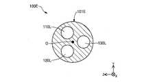
中間区間S2は、シャフト101内に、第1ルーメン110L、第2ルーメン120L、及び第3ルーメン130Lを含む区間である。図4(A)のC-C断面に示すように、中間区間S2において、シャフト101は円形状の横断面を有している。具体的には、中間区間S2では、それぞれ隣接して配置された第1インナーシャフト110、第2インナーシャフト120、及び第3インナーシャフト130が、第1~第3インナーシャフト110,120,130の外周面側に配置された封止部材102により固定されている。また、中間区間S2では、封止部材102の外形が、円形状の横断面になるように成形されている。なお、本実施形態において「円形状」とは、軸線に対して完全に対称な円形状だけでなく、非対称な一部分を有する略円形状を含み得る意味である。 The intermediate section S2 is a section that includes thefirst lumen 110L, thesecond lumen 120L, and thethird lumen 130L within theshaft 101 . As shown in the CC section of FIG. 4A, theshaft 101 has a circular cross section in the intermediate section S2. Specifically, in the intermediate section S2, the firstinner shaft 110, the secondinner shaft 120, and the thirdinner shaft 130, which are arranged adjacent to each other, are separated from the first to thirdinner shafts 110, 120, 130. It is fixed by a sealingmember 102 arranged on the outer peripheral surface side. Further, in the intermediate section S2, the outer shape of the sealingmember 102 is formed to have a circular cross section. In this embodiment, the term “circular” means not only a circular shape that is completely symmetrical with respect to the axis, but also a substantially circular shape that has an asymmetrical portion.

基端区間S3は、シャフト101内に、第2ルーメン120Lと第3ルーメン130Lとを含む区間である。図5(B)のF-F断面に示すように、基端区間S3において、シャフト101は円形状の横断面を有している。具体的には、基端区間S3では、補強部材140の内側(ルーメン140L)に、第2インナーシャフト120と第3インナーシャフト130とが隣接した状態で収容されている。図2に示すように、補強部材140は、テーパ部141と、本体部142とを有する管状の部材である。テーパ部141は、補強部材140の先端部に設けられており、先端側から基端側に向かって外径が徐々に拡径した部分である。本体部142は、略一定の外形を有する部分である。図5(B)に示すように、本実施形態の補強部材140は、樹脂製の管状体に、素線を網目織りにしたメッシュ形状のブレード143が埋設された構成である。なお、図5(B)に示すように、補強部材140の中心は、シャフト101の中間区間S2の中心を通る軸線Oとは一致していない。しかし、補強部材140の中心と、シャフト101の中間区間S2の中心を通る軸線Oとは、一致させてもよい。また、図示の例では、ルーメン140Lには何も充填されていないが、例えば、ルーメン140Lには封止部材102が充填されていてもよい。 The proximal section S3 is a section that includes thesecond lumen 120L and thethird lumen 130L within theshaft 101 . As shown in the FF cross section of FIG. 5B, theshaft 101 has a circular cross section in the base end section S3. Specifically, in the proximal section S3, the secondinner shaft 120 and the thirdinner shaft 130 are housed inside the reinforcing member 140 (lumen 140L) in a state of being adjacent to each other. As shown in FIG. 2 , the reinforcingmember 140 is a tubular member having a taperedportion 141 and abody portion 142 . The taperedportion 141 is provided at the distal end portion of the reinforcingmember 140 and is a portion whose outer diameter gradually increases from the distal end side to the proximal end side. Thebody portion 142 is a portion having a substantially constant outer shape. As shown in FIG. 5(B), the reinforcingmember 140 of the present embodiment has a configuration in which a mesh-shapedbraid 143 is embedded in a tubular body made of resin. Note that the center of the reinforcingmember 140 does not coincide with the axis O passing through the center of the intermediate section S2 of theshaft 101, as shown in FIG. 5B. However, the center of the reinforcingmember 140 and the axis O passing through the center of the intermediate section S2 of theshaft 101 may be aligned. In the illustrated example, thelumen 140L is not filled with anything, but thelumen 140L may be filled with the sealingmember 102, for example.

図2に戻り、説明を続ける。シャフト101は、先端区間S1と中間区間S2との間であって、第3ルーメン130Lの第3先端開口130aに対応する位置に、第1徐変区間S11を有している。また、シャフト101は、中間区間S2と基端区間S3との間であって、第1ルーメン110Lの第1基端開口110bに対応する位置に、第2徐変区間S12を有している。さらに、シャフト101は、第2徐変区間S12と基端区間S3との間に、接続区間S13を有している。 Returning to FIG. 2, the description is continued. Theshaft 101 has a first gradually changing section S11 between the tip section S1 and the intermediate section S2 and at a position corresponding to the third tip opening 130a of thethird lumen 130L. Further, theshaft 101 has a second gradually changing section S12 between the intermediate section S2 and the proximal section S3 and at a position corresponding to the firstproximal opening 110b of thefirst lumen 110L. Further, theshaft 101 has a connecting section S13 between the second gradually changing section S12 and the proximal section S3.

第1徐変区間S11は、第3先端開口130aに対応する位置、すなわち、第3ルーメン130Lの第3先端に対応する位置に設けられた区間である。図3(B)のB-B断面に示すように、第1徐変区間S11では、シャフト101の横断面形状が、先端側から基端側に向かって、楕円形状から円形状に徐変していく。換言すれば、第1徐変区間S11のシャフト101の横断面形状は、先端側では図3(A)に示す楕円形状により近い形状となり、基端側では図4(A)に示す円形状により近い形状となる。図3(B)に示すように、第1徐変区間S11では、第1インナーシャフト110、第2インナーシャフト120、及び第3インナーシャフト130が隣接して配置されている。また、第3インナーシャフト130の先端部のうち、第1及び第2インナーシャフト110,120と接触していない外側部分が斜めにカットされている。この状態で、第1インナーシャフト110、第2インナーシャフト120、及び第3インナーシャフト130は、外周面側に配置された封止部材102により固定されている。 The first gradually changing section S11 is a section provided at a position corresponding to thethird tip opening 130a, that is, a position corresponding to the third tip of thethird lumen 130L. As shown in the BB cross section of FIG. 3B, in the first gradually changing section S11, the cross-sectional shape of theshaft 101 gradually changes from an elliptical shape to a circular shape from the distal end side to the proximal end side. To go. In other words, the cross-sectional shape of theshaft 101 in the first gradually changing section S11 has a shape closer to the elliptical shape shown in FIG. close shape. As shown in FIG. 3B, in the first gradual change section S11, the firstinner shaft 110, the secondinner shaft 120, and the thirdinner shaft 130 are arranged adjacent to each other. Further, the outer portion of the distal end portion of the thirdinner shaft 130, which is not in contact with the first and secondinner shafts 110, 120, is obliquely cut. In this state, the firstinner shaft 110, the secondinner shaft 120, and the thirdinner shaft 130 are fixed by the sealingmember 102 arranged on the outer peripheral surface side.

第2徐変区間S12は、第1基端開口110bに対応する位置、すなわち、第1ルーメン110Lの第1基端に対応する位置に設けられた区間である。図4(B)のD-D断面に示すように、第2徐変区間S12では、シャフト101の横断面形状が、先端側から基端側に向かって、円形状から楕円形状に徐変していく。換言すれば、第2徐変区間S12のシャフト101の横断面形状は、先端側では図4(A)に示す円形状により近い形状となり、基端側では図5(A)に示す楕円形状により近い形状となる。図4(B)に示すように、第2徐変区間S12では、第1インナーシャフト110、第2インナーシャフト120、及び第3インナーシャフト130が隣接して配置されている。また、第1インナーシャフト110の先端部のうち、第2及び第3インナーシャフト120,130と接触していない外側部分が斜めにカットされている。この状態で、第1インナーシャフト110、第2インナーシャフト120、及び第3インナーシャフト130は、外周面側に配置された封止部材102により固定されている。 The second gradually changing section S12 is a section provided at a position corresponding to the first base end opening 110b, that is, a position corresponding to the first base end of thefirst lumen 110L. As shown in the DD section of FIG. 4B, in the second gradually changing section S12, the cross-sectional shape of theshaft 101 gradually changes from a circular shape to an elliptical shape from the distal end side to the proximal end side. To go. In other words, the cross-sectional shape of theshaft 101 in the second gradually changing section S12 is closer to the circular shape shown in FIG. close shape. As shown in FIG. 4B, in the second gradual change section S12, the firstinner shaft 110, the secondinner shaft 120, and the thirdinner shaft 130 are arranged adjacent to each other. Further, the outer portion of the distal end portion of the firstinner shaft 110, which is not in contact with the second and thirdinner shafts 120, 130, is obliquely cut. In this state, the firstinner shaft 110, the secondinner shaft 120, and the thirdinner shaft 130 are fixed by the sealingmember 102 arranged on the outer peripheral surface side.

接続区間S13は、第2徐変区間S12と基端区間S3との間に設けられており、シャフト101内に、第2ルーメン120Lと第3ルーメン130Lとを含む区間である。図5(A)のE-E断面に示すように、接続区間S13において、シャフト101は楕円形状の横断面を有している。具体的には、接続区間S13では、隣接して配置された第2インナーシャフト120と第3インナーシャフト130とが、第2,3インナーシャフト120,130の外周面側に配置された封止部材102により固定されている。また、接続区間S13では、封止部材102の外形が、楕円形状の横断面になるように成形されている。 The connection section S13 is provided between the second gradually changing section S12 and the proximal section S3, and is a section that includes thesecond lumen 120L and thethird lumen 130L in theshaft 101. As shown in the EE cross section of FIG. 5A, theshaft 101 has an elliptical cross section at the connection section S13. Specifically, in the connection section S13, the secondinner shaft 120 and the thirdinner shaft 130 that are adjacent to each other are connected to the sealing member that is disposed on the outer peripheral surface side of the second and thirdinner shafts 120 and 130. 102. Further, in the connection section S13, the outer shape of the sealingmember 102 is formed to have an elliptical cross section.

図2に戻り、説明を続ける。シャフト101のうち、先端区間S1よりも先端側には、シャフト101内に第1ルーメン110Lのみを含む突出部101pが形成されている。突出部101pの先端側の一部分には、突出部101pの周囲を取り囲むようにして、先端チップ103が接合されている。先端チップ103は、先端側に向かって外径が縮径した筒状の部材である。なお、先端チップ103は任意の形状とできる。先端チップ103は、視認性を向上させるために着色されていてもよく、放射線不透過性を有する材料により形成されていてもよい。先端チップ103とシャフト101との接合には、例えば、熱溶融による樹脂同士の接合や、エポキシ系接着剤などの絶縁性の接着剤による接合を採用できる。 Returning to FIG. 2, the description is continued. A projectingportion 101p including only thefirst lumen 110L is formed in theshaft 101 on the distal end side of the distal end section S1 of theshaft 101 . Adistal tip 103 is joined to a portion of the distal end side of the projectingportion 101p so as to surround the periphery of the projectingportion 101p. Thedistal tip 103 is a cylindrical member whose outer diameter is reduced toward the distal end. Note that thedistal tip 103 can have any shape. Thedistal tip 103 may be colored to improve visibility, and may be made of a radiopaque material. For joining thetip 103 and theshaft 101, for example, joining of resins by heat melting or joining with an insulating adhesive such as an epoxy adhesive can be adopted.

シャフト101の外周面のうち、先端区間S1の基端部(換言すれば、第3先端開口130aよりも先端側の一部分)には、マーカー104が接合されている。マーカー104は、シャフト101の外周面に沿った半円形状の部材である。マーカー104は、視認性を向上させるために着色されていてもよく、放射線不透過性を有する材料により形成されていてもよい。マーカー104とシャフト101との接合には、例えば、熱溶融による樹脂同士の接合や、エポキシ系接着剤などの絶縁性の接着剤による接合を採用できる。 Amarker 104 is joined to the proximal end portion of the distal section S1 (in other words, a portion closer to the distal end than the thirddistal opening 130a) of the outer peripheral surface of theshaft 101 . Themarker 104 is a semicircular member along the outer peripheral surface of theshaft 101 . Themarker 104 may be colored to improve visibility, and may be made of a radiopaque material. For bonding themarker 104 and theshaft 101, for example, bonding between resins by heat melting or bonding with an insulating adhesive such as an epoxy adhesive can be adopted.

シャフト101のうち、基端区間S3よりも基端側では、シャフト101が二股に分岐している。分岐したシャフト101のうち、一方は第3ルーメン130Lを含む第3インナーシャフト130であり、他方は第2ルーメン120Lを含む第2インナーシャフト120である。なお、基端区間S3よりも基端側では、第2インナーシャフト120と第3インナーシャフト130との少なくとも一方は、補強のための別途の管状体により覆われていてもよい。 Theshaft 101 is bifurcated on the proximal end side of the proximal section S3. One of the branchedshafts 101 is the thirdinner shaft 130 including thethird lumen 130L, and the other is the secondinner shaft 120 including thesecond lumen 120L. At least one of the secondinner shaft 120 and the thirdinner shaft 130 may be covered with a separate tubular body for reinforcement on the proximal side of the proximal section S3.

第3インナーシャフト130の基端部には、中空のコネクタ160が固定されている。コネクタ160は、一対の羽根部を有し、術者によって把持される部材である。図2に示すように、コネクタ160の基端側の開口が、上述した第3基端開口130bに相当する。第2インナーシャフト120の基端部には、調節器150が固定されている。調節器150は、第2ルーメン120Lにおけるイメージングセンサ200の前進後退を行うための操作部である。調節器150は、術者が操作可能なダイヤルを備えており、ダイヤルを回転させることで、第2ルーメン120Lに挿入されたイメージングセンサ200が、前進、または後退可能に構成されている。図2に示すように、調節器150の基端側の開口が、上述した第2基端開口120bに相当する。 Ahollow connector 160 is fixed to the proximal end of the thirdinner shaft 130 . Theconnector 160 is a member that has a pair of blades and is gripped by the operator. As shown in FIG. 2, the proximal opening of theconnector 160 corresponds to the above-described thirdproximal opening 130b. Anadjuster 150 is fixed to the proximal end of the secondinner shaft 120 . Theadjuster 150 is an operation unit for advancing and retreating theimaging sensor 200 in thesecond lumen 120L. Theadjuster 150 has a dial that can be operated by the operator, and by rotating the dial, theimaging sensor 200 inserted into thesecond lumen 120L can move forward or backward. As shown in FIG. 2, the proximal opening ofadjuster 150 corresponds to secondproximal opening 120b described above.

第1インナーシャフト110、第2インナーシャフト120、第3インナーシャフト130、封止部材102、補強部材140のブレード143を除く肉厚部、コネクタ160、及び調節器150は、例えば、ポリアミドなどのナイロン樹脂、ポリエチレン、ポリプロピレン、エチレン-プロピレン共重合体などのポリオレフィン、ポリエチレンテレフタラートなどのポリエステル、ポリ塩化ビニル、エチレン-酢酸ビニル共重合体、架橋型エチレン-酢酸ビニル共重合体、ポリウレタンなどの熱可塑性樹脂、ポリアミドエラストマー、ポリオレフィンエラストマー、ポリウレタンエラストマー、シリコーンゴム、ラテックスゴム等の公知の材料により形成され得る。第1インナーシャフト110、第2インナーシャフト120、第3インナーシャフト130、封止部材102、補強部材140のブレード143を除く肉厚部、コネクタ160、及び調節器150は、同一の材料で形成されていてもよく、少なくとも一部、または全部が、他とは異なる材料により形成されていてもよい。なお、第1インナーシャフト110、第2インナーシャフト120、第3インナーシャフト130、及び封止部材102について、少なくとも第3先端開口130aの近傍に位置する一部分については、生体組織との音響インピーダンスの差が小さい樹脂、例えば、ポリエチレンで形成されることが好ましい。これは、イメージングセンサ200から生体組織に向けて発信される超音波を阻害しないためである。 The firstinner shaft 110, the secondinner shaft 120, the thirdinner shaft 130, the sealingmember 102, the thick portion of the reinforcingmember 140 excluding theblade 143, theconnector 160, and theadjuster 150 are made of nylon such as polyamide, for example. Polyolefins such as resins, polyethylene, polypropylene, ethylene-propylene copolymers, polyesters such as polyethylene terephthalate, polyvinyl chloride, ethylene-vinyl acetate copolymers, cross-linked ethylene-vinyl acetate copolymers, thermoplastics such as polyurethanes It can be made of known materials such as resins, polyamide elastomers, polyolefin elastomers, polyurethane elastomers, silicone rubbers, and latex rubbers. The firstinner shaft 110, the secondinner shaft 120, the thirdinner shaft 130, the sealingmember 102, the thick portion of the reinforcingmember 140 excluding theblade 143, theconnector 160, and theadjuster 150 are made of the same material. At least part or all of it may be made of a material different from the others. Regarding the firstinner shaft 110, the secondinner shaft 120, the thirdinner shaft 130, and the sealingmember 102, at least a portion located near thethird tip opening 130a has a difference in acoustic impedance from living tissue. It is preferably made of a resin with a small volatility, such as polyethylene. This is because the ultrasonic waves emitted from theimaging sensor 200 toward the living tissue are not obstructed.

先端チップ103及びマーカー104は、柔軟性を有する樹脂材料、例えば、ポリウレタンエラストマーで形成できる。先端チップ103及びマーカー104は、放射線不透過性を有する樹脂材料や金属材料により形成してもよい。例えば、放射線不透過性の樹脂材料を用いる場合、ポリアミド樹脂、ポリオレフィン樹脂、ポリエステル樹脂、ポリウレタン樹脂、シリコン樹脂、フッ素樹脂等に対して、三酸化ビスマス、タングステン、硫酸バリウム等の放射線不透過材料を混ぜて形成できる。例えば、放射線不透過性の金属材料を用いる場合、金、白金、タングステン、またはこれらの元素を含む合金(例えば、白金ニッケル合金)等で形成できる。先端チップ103及びマーカー104は、同一の材料で形成されていてもよく、異なる材料により形成されていてもよい。 Thedistal tip 103 and themarker 104 can be made of a flexible resin material such as polyurethane elastomer. Thedistal tip 103 and themarker 104 may be made of radiopaque resin material or metal material. For example, when using a radiopaque resin material, a radiopaque material such as bismuth trioxide, tungsten, barium sulfate, etc. is used for polyamide resin, polyolefin resin, polyester resin, polyurethane resin, silicone resin, fluorine resin, etc. You can mix and form. For example, when using a radiopaque metal material, it can be made of gold, platinum, tungsten, or an alloy containing these elements (for example, platinum-nickel alloy). Thedistal tip 103 and themarker 104 may be made of the same material or may be made of different materials.

図6は、イメージングセンサ200の概略図である。イメージングセンサ200は、長尺状の外形を有し、生体組織の情報を取得する「センサ」である。イメージングセンサ200は、トランスデューサ201と、ドライビングケーブル202と、コネクタ203と、モータドライブ204とを有している。トランスデューサ201は、生体組織に向けて超音波を発信し、生体組織を伝搬して反射した超音波を受信する超音波探触子(超音波振動子、圧電体、超音波送受信素子、超音波素子とも呼ばれる)を備えている。ドライビングケーブル202はその内側に、トランスデューサ201とモータドライブ204とを電気的に接続する同軸線を有する。コネクタ203は、ドライビングケーブル202の同軸線とトランスデューサ201の回転を制御するモータドライブ204とを接続する。なお、モータドライブ204はケーブル50によりイメージングコンソール300と電気的に接続されている。 FIG. 6 is a schematic diagram ofimaging sensor 200 . Theimaging sensor 200 is a "sensor" that has an elongated outer shape and acquires information on living tissue.Imaging sensor 200 includestransducer 201 , drivingcable 202 ,connector 203 andmotor drive 204 . Thetransducer 201 is an ultrasonic probe (ultrasonic transducer, piezoelectric body, ultrasonic transmitting/receiving element, ultrasonic element (also called The drivingcable 202 has coaxial lines inside that electrically connect thetransducer 201 and themotor drive 204 . Aconnector 203 connects the coaxial line of the drivingcable 202 and amotor drive 204 that controls the rotation of thetransducer 201 . Note that themotor drive 204 is electrically connected to theimaging console 300 via acable 50 .

図1に示すイメージングコンソール300は、イメージングセンサ200を制御すると共に、画像を生成し、表示する。具体的には、イメージングコンソール300は、調節器150の操作に応じて、第2ルーメン120L内のトランスデューサ201を、シャフト101の長手方向(X軸方向)に移動させ、また、シャフト101の周方向(YZ軸方向)に回転させる。また、イメージングコンソール300は、図示しない入力手段を介した術者の操作に応じて、トランスデューサ201から超音波を発信し、トランスデューサ201によって反射波を受信させる。トランスデューサ201が受信した反射波は、ドライビングケーブル202及びケーブル50を介して、イメージングコンソール300に送信される。イメージングコンソール300は、受信した反射波の強度に応じた濃淡の諧調を付した画像(2次元画像)を生成し、生成した画像をディスプレイ302に表示させる。以降、イメージングセンサ200により取得され、ディスプレイ302に表示された画像を「センサ画像」とも呼ぶ。Imaging console 300 shown in FIG. 1controls imaging sensor 200 and generates and displays images. Specifically, theimaging console 300 moves thetransducer 201 in thesecond lumen 120L in the longitudinal direction (X-axis direction) of theshaft 101 and in the circumferential direction of theshaft 101 in accordance with the operation of theadjuster 150. (in the YZ-axis direction). In addition, theimaging console 300 transmits ultrasonic waves from thetransducer 201 and causes thetransducer 201 to receive reflected waves in response to an operator's operation via input means (not shown). Reflected waves received bytransducer 201 are transmitted toimaging console 300 via drivingcable 202 andcable 50 . Theimaging console 300 generates an image (two-dimensional image) with gradation according to the intensity of the received reflected wave, and causes thedisplay 302 to display the generated image. Hereinafter, an image acquired by theimaging sensor 200 and displayed on thedisplay 302 will also be referred to as a "sensor image".

図1に示す貫通用ガイドワイヤ400は、先端に尖状部401を有する長尺な医療デバイスである。尖状部401は、基端側から先端側に向かって、やじり形状或いは楔形状とされた部分である。貫通用ガイドワイヤ400は、先端に設けられた尖状部401によって、生体組織を貫通することができる。貫通用ガイドワイヤ400は「生体組織を貫通するガイドワイヤ」に相当する。図1に示すモノレールガイドワイヤ500は、血管にカテーテル100を挿入する際に用いられる長尺な医療デバイスである。モノレールガイドワイヤ500は、単に「ガイドワイヤ」とも呼ばれる。なお、図示の例では、貫通用ガイドワイヤ400のうち、カテーテル100の外側に露出した一部分には、トルカー402が取り付けられている。トルカー402は、術者によるデバイスの把持及び回転操作を容易にするための器具である。トルカー402は、モノレールガイドワイヤ500に対して取り付けられてもよく、省略されてもよい。 A penetratingguidewire 400 shown in FIG. 1 is an elongated medical device having a pointedportion 401 at its distal end. The pointedportion 401 is a portion that has an arrow shape or a wedge shape from the proximal side toward the distal side. The penetratingguidewire 400 can penetrate living tissue with apointed portion 401 provided at its distal end. The penetratingguidewire 400 corresponds to "a guidewire that penetrates a living tissue". Monorail guidewire 500 shown in FIG. 1 is an elongated medical device used when insertingcatheter 100 into a blood vessel. Monorail guidewire 500 is also simply referred to as a "guidewire". In the illustrated example, atorquer 402 is attached to a part of the penetratingguidewire 400 that is exposed to the outside of thecatheter 100 . Thetorquer 402 is an instrument that facilitates grasping and rotating operation of the device by the operator. Thetorquer 402 may be attached to the monorail guidewire 500 or omitted.

図7及び図8は、再開通カテーテルシステム1の使用方法について説明する図である。図7及び図8では、生体管腔の一例としての冠動脈80と、冠動脈80に発生したCTO81と、冠動脈80の内膜または内膜下に形成された偽腔82(モノレールガイドワイヤ500により形成された真腔以外の全ての解離腔)と、真腔84と、偽腔82と真腔84との間に存在する線維性皮膜またはプラーク83(以下「線維性皮膜83」とも呼ぶ)と、をそれぞれ示す。線維性皮膜83は、CTO病変の表面に繊維状に形成されることがある。なお、図8では、カテーテル100の内側に挿入されているイメージングセンサ200及び貫通用ガイドワイヤ400を破線で図示する。 FIGS. 7 and 8 are diagrams explaining how to use therecanalization catheter system 1. FIG. 7 and 8 show acoronary artery 80 as an example of a biological lumen, aCTO 81 generated in thecoronary artery 80, and afalse lumen 82 formed in or under the intima of the coronary artery 80 (formed by the monorail guide wire 500). all dissected lumens other than the true lumen), thetrue lumen 84, and the fibrous capsule orplaque 83 existing between thefalse lumen 82 and the true lumen 84 (hereinafter also referred to as "fibrous capsule 83"). each shown.Fibrous caps 83 may form fibrously on the surface of CTO lesions. In FIG. 8, theimaging sensor 200 and the penetratingguide wire 400 inserted inside thecatheter 100 are illustrated by dashed lines.

図7(A)は、冠動脈80にモノレールガイドワイヤ500を挿入した様子を示す。図7(A)では、術者が操作するモノレールガイドワイヤ500が、冠動脈80の内膜に迷入し、あるいは内膜下で偽腔82を形成している。 FIG. 7A shows how the monorail guidewire 500 is inserted into thecoronary artery 80. FIG. In FIG. 7A, themonorail guide wire 500 manipulated by the operator has entered the intima of thecoronary artery 80 or has formed afalse lumen 82 under the intima.

図7(B)は、モノレールガイドワイヤ500を用いてカテーテル100をデリバリする様子を示す。術者は、患者の体外において、モノレールガイドワイヤ500の基端部を、カテーテル100の第1先端開口110aから第1ルーメン110L内に挿入する。術者は、第1ルーメン110L内部において、モノレールガイドワイヤ500を基端側に押し進め、モノレールガイドワイヤ500の基端部を、カテーテル100の第1基端開口110bから外部へと引き出す。このように、第1基端開口110bは、いわゆるラピッドエクスチェンジ型のカテーテルの「ポート」として機能するため、第1ルーメン110L内においてモノレールガイドワイヤ500を送り出す距離を短くできる。その後、術者は、図7(B)に示すように、モノレールガイドワイヤ500に沿わせて、カテーテル100を偽腔82までデリバリする。 FIG. 7B shows delivery ofcatheter 100 usingmonorail guidewire 500 . Outside the patient's body, the operator inserts the proximal end of the monorail guidewire 500 into thefirst lumen 110L from the firstdistal end opening 110a of thecatheter 100 . The operator pushes the monorail guidewire 500 proximally inside thefirst lumen 110L, and pulls out the proximal end of the monorail guidewire 500 from the firstproximal opening 110b of thecatheter 100 to the outside. In this way, the firstproximal opening 110b functions as a "port" for a so-called rapid exchange catheter, so the distance through which the monorail guidewire 500 is delivered within thefirst lumen 110L can be shortened. Thereafter, the operator delivers thecatheter 100 to thefalse lumen 82 along the monorail guidewire 500, as shown in FIG. 7(B).

図8(A)は、カテーテル100及びイメージングセンサ200の位置を調整する様子を示す。術者は、次のa1~a3に示す各位置の調整を行う。
(a1)カテーテル100の長手方向(図1:X軸方向)における位置の調整。術者は、カテーテル100を冠動脈80に沿って移動させることで、カテーテル100の第3先端開口130aを、貫通用ガイドワイヤ400による真腔84への穿通のために最適な位置に配置する。調整a1は、センサ画像上の冠動脈80の位置、または、X線画像上のマーカー104の位置を確認しつつ、実施できる。
(a2)カテーテル100の周方向(図1:YZ軸方向)における向きの調整。術者は、カテーテル100を周方向に回転させることで、カテーテル100が、図示の向き(すなわち、第3先端開口130aが、CTO81側に位置する向き)となるよう調整する。調整a2は、センサ画像上のモノレールガイドワイヤ500と冠動脈80との位置関係を確認しつつ、実施できる。
(a3)イメージングセンサ200のトランスデューサ201についての、長手方向(図1:X軸方向)における位置の調整。術者は、調節器150を操作することで、トランスデューサ201が、貫通用ガイドワイヤ400の穿通を観察するために適した位置となるよう、トランスデューサ201を移動させる。調整a3は、センサ画像上の冠動脈80を確認しつつ、実施できる。
FIG. 8A shows how the positions of thecatheter 100 and theimaging sensor 200 are adjusted. The operator adjusts each position shown in the following a1 to a3.
(a1) Adjusting the position of thecatheter 100 in the longitudinal direction ( FIG. 1 : X-axis direction). The operator moves thecatheter 100 along thecoronary artery 80 to position the thirddistal end opening 130a of thecatheter 100 at the optimum position for penetration of the penetratingguidewire 400 into thetrue lumen 84 . The adjustment a1 can be performed while confirming the position of thecoronary artery 80 on the sensor image or the position of themarker 104 on the X-ray image.
(a2) Adjusting the orientation of thecatheter 100 in the circumferential direction (the YZ-axis direction in FIG. 1). By rotating thecatheter 100 in the circumferential direction, the operator adjusts thecatheter 100 so that it is oriented as shown in the figure (that is, thethird tip opening 130a is positioned on theCTO 81 side). The adjustment a2 can be performed while confirming the positional relationship between the monorail guidewire 500 and thecoronary artery 80 on the sensor image.
(a3) Adjusting the position of thetransducer 201 of theimaging sensor 200 in the longitudinal direction ( FIG. 1 : X-axis direction). The operator operates theadjuster 150 to move thetransducer 201 so that thetransducer 201 is in a position suitable for observing the penetration of the penetratingguidewire 400 . The adjustment a3 can be performed while confirming thecoronary artery 80 on the sensor image.

図8(B)は、貫通用ガイドワイヤ400で生体組織を貫通する様子を示す。術者は、カテーテル100のコネクタ160を把持して、貫通用ガイドワイヤ400の先端部を、カテーテル100の第3基端開口130bから第3ルーメン130L内に挿入する。術者は、第3ルーメン130L内部において、貫通用ガイドワイヤ400を先端側に押し進める。術者は、センサ画像上の貫通用ガイドワイヤ400の先端部(尖状部401)の位置を確認しつつ、尖状部401を、上述した穿通の至適部位に誘導する。その後、術者は、貫通用ガイドワイヤ400の尖状部401を用いてCTO81(生体組織)を貫通し、貫通用ガイドワイヤ400の先端部を真腔84に到達させる。 FIG. 8B shows how the penetratingguidewire 400 penetrates the living tissue. The operator grasps theconnector 160 of thecatheter 100 and inserts the distal end portion of the penetratingguidewire 400 from the third base end opening 130b of thecatheter 100 into thethird lumen 130L. The operator pushes the penetratingguidewire 400 forward inside thethird lumen 130L. The operator guides the tip portion (pointed portion 401) of the penetratingguidewire 400 on the sensor image while guiding the pointedportion 401 to the above-described optimal site for penetration. After that, the operator penetrates the CTO 81 (living tissue) using the pointedportion 401 of the penetratingguide wire 400 to allow the distal end portion of the penetratingguide wire 400 to reach thetrue lumen 84 .

このような方法により、再開通カテーテルシステム1によるCTO81の開通が可能となる。なお、上述した方法はあくまで一例であり、再開通カテーテルシステム1は、種々の手技で使用できる。例えば、再開通カテーテルシステム1は、偽腔82から真腔84へのアプローチに限らず、近位側の真腔84から遠位側の真腔84へのCTOを貫通するアプローチを行う際に使用されてもよい。 Such a method allows therecanalization catheter system 1 to open theCTO 81 . The method described above is merely an example, and therecanalization catheter system 1 can be used in various procedures. For example, therecanalization catheter system 1 is used not only for the approach from thefalse lumen 82 to thetrue lumen 84 but also for the approach that penetrates the CTO from the proximaltrue lumen 84 to the distaltrue lumen 84. may be

図9は、図8(B)のG-G線におけるカテーテル100及びCTO81の横断面図である。図9を用いて、本実施形態のカテーテル100の効果例について説明する。図8(A)で説明した調整a1~a3(特に調整a2)の結果、カテーテル100は、貫通用ガイドワイヤ400を含む第3ルーメン130Lを、リエントリ方向(真腔84がある方向)に向けた状態とされる。この時、図9に示すように、リエントリ方向と逆側(換言すれば、真腔84から遠い側)には、第1ルーメン110Lと第2ルーメン120Lとが、第3ルーメン130Lに隣り合ってそれぞれ位置した状態となる。この状態で、図8(B)で説明したように、貫通用ガイドワイヤ400の尖状部401を用いてCTO81を貫通する。ここで、CTO81を貫通する際、貫通用ガイドワイヤ400には、CTO81(生体組織)からの反力が加わる。しかし、本実施形態のカテーテル100では、図9に示すように、第1ルーメン110Lと第2ルーメン120L、及び、第1ルーメン110L内のモノレールガイドワイヤ500と第2ルーメン120L内のイメージングセンサ200によって、第3ルーメン130L内の貫通用ガイドワイヤ400を支持することができる。換言すると、図8(B)のG-G線におけるカテーテル100及びCTO81の横断面において、貫通用ガイドワイヤ400は、CTO81の反対側に位置する両側の2箇所において、第1ルーメン110Lと第2ルーメン120L、及び、第1ルーメン110L内のモノレールガイドワイヤ500と第2ルーメン120L内のイメージングセンサ200によって、支持されている。このため、CTO81からの反力によるカテーテル100の回転を抑制することができると共に、貫通用ガイドワイヤ400に対して、CTO81を貫通し、真腔84へと貫通用ガイドワイヤ400を再入させるために十分な力を加えることができる。 FIG. 9 is a cross-sectional view ofcatheter 100 andCTO 81 taken along line GG of FIG. 8(B). An example of the effects of thecatheter 100 of this embodiment will be described with reference to FIG. As a result of the adjustments a1 to a3 (especially the adjustment a2) described in FIG. 8A, thecatheter 100 directs thethird lumen 130L including the penetratingguidewire 400 in the reentry direction (the direction in which thetrue lumen 84 exists). state. At this time, as shown in FIG. 9, thefirst lumen 110L and thesecond lumen 120L are adjacent to thethird lumen 130L on the side opposite to the reentry direction (in other words, the side far from the true lumen 84). are positioned respectively. In this state, theCTO 81 is penetrated using the pointedportion 401 of the penetratingguide wire 400 as described with reference to FIG. 8(B). Here, when penetrating theCTO 81 , a reaction force from the CTO 81 (living tissue) is applied to the penetratingguide wire 400 . However, in thecatheter 100 of the present embodiment, as shown in FIG. 9, by thefirst lumen 110L and thesecond lumen 120L, and themonorail guide wire 500 in thefirst lumen 110L and theimaging sensor 200 in thesecond lumen 120L, , can support the penetratingguidewire 400 within thethird lumen 130L. In other words, in the cross section ofcatheter 100 andCTO 81 taken along line GG in FIG. It is supported bylumen 120L and monorail guidewire 500 infirst lumen 110L andimaging sensor 200 insecond lumen 120L. Therefore, the rotation of thecatheter 100 due to the reaction force from theCTO 81 can be suppressed, and thepenetration guide wire 400 penetrates theCTO 81 and re-enters thetrue lumen 84 with respect to thepenetration guide wire 400 . sufficient force can be applied to

図10は、比較例のカテーテル100x及びCTO81の横断面図である。比較例のカテーテル100xは、上述した第1インナーシャフト110を有していない。比較例のカテーテル100xは、第1ルーメン110Lと第3ルーメン130Lとが個別に存在せず、第3インナーシャフト130の内側が、第1ルーメン110L(モノレールガイドワイヤルーメン)の機能と、第3ルーメン130L(貫通用ガイドワイヤルーメン)の機能とを果たす。比較例のカテーテル100xの場合、術者は、カテーテル100xの第3ルーメン130Lに対してモノレールガイドワイヤ500を挿入した状態で、カテーテル100xをデリバリする。そして術者は、図8(A)で説明した方法を用いてカテーテル100xの位置を調整した後、第3ルーメン130Lからモノレールガイドワイヤ500を抜去する。その後、術者は、カテーテル100xの第3ルーメン130Lに対して貫通用ガイドワイヤ400を挿入する。 FIG. 10 is a cross-sectional view ofcomparative catheter 100x and CTO81. Acomparative catheter 100x does not have the firstinner shaft 110 described above. In thecatheter 100x of the comparative example, thefirst lumen 110L and thethird lumen 130L do not exist separately, and the inner side of the thirdinner shaft 130 functions as thefirst lumen 110L (monorail guide wire lumen) and as the third lumen. 130L (penetrating guidewire lumen). In the case of thecatheter 100x of the comparative example, the operator delivers thecatheter 100x with the monorail guidewire 500 inserted into thethird lumen 130L of thecatheter 100x. After adjusting the position of thecatheter 100x using the method described with reference to FIG. 8A, the operator removes themonorail guide wire 500 from thethird lumen 130L. After that, the operator inserts the penetratingguidewire 400 into thethird lumen 130L of thecatheter 100x.

図10(A)は、貫通用ガイドワイヤ400を含む第3ルーメン130Lを、リエントリ方向(真腔84がある方向)に向けた状態を示す。この時、リエントリ方向と逆側(真腔84から遠い側)には、第2ルーメン120Lのみが位置した状態となる。この状態で、貫通用ガイドワイヤ400の尖状部401を用いてCTO81を貫通する操作を行う。すると、貫通用ガイドワイヤ400がCTO81(生体組織)からの反力を受けることによって、図10(B)に示すように、カテーテル100xが周方向に回転してしまう。これは、図9で説明した本実施形態のカテーテル100と比べて、比較例のカテーテル100xでは、第3ルーメン130L内の貫通用ガイドワイヤ400が、十分な支持力を得られないことに起因する。換言すると、貫通用ガイドワイヤ400は、CTO81の反対側に位置する1箇所のみでしか支持されていないことに起因する。なお、図10(B)は、カテーテル100xが反力により回転する様子を図示している。 FIG. 10A shows a state in which thethird lumen 130L including the penetratingguidewire 400 is oriented in the reentry direction (the direction in which thetrue lumen 84 is present). At this time, only thesecond lumen 120L is positioned on the side opposite to the reentry direction (the side farther from the true lumen 84). In this state, an operation of penetrating theCTO 81 is performed using the pointedportion 401 of the penetratingguide wire 400 . Then, the penetratingguide wire 400 receives a reaction force from the CTO 81 (living tissue), causing thecatheter 100x to rotate in the circumferential direction as shown in FIG. 10(B). This is because the penetration guidewire 400 in thethird lumen 130L cannot obtain a sufficient supporting force in thecatheter 100x of the comparative example as compared with thecatheter 100 of the present embodiment described with reference to FIG. . In other words, the penetratingguidewire 400 is supported only at one point opposite theCTO 81 . Note that FIG. 10B illustrates how thecatheter 100x rotates due to the reaction force.

以上のように、第1実施形態の再開通カテーテルシステム1によれば、カテーテル100のシャフト101は、モノレールガイドワイヤ500を挿入するための第1ルーメン110Lと、画像用のイメージングセンサ200を挿入するための第2ルーメン120Lと、貫通用ガイドワイヤ400を挿入するための第3ルーメン130Lとを備えるため、イメージングセンサ200のガイド下での手技を実現可能なデバイス(カテーテル100)を提供できる。また、図4(A)に示すように、シャフト101は、第1ルーメン110Lと第2ルーメン120Lと第3ルーメン130Lを含む中間区間S2を有し、当該中間区間S2の横断面は円形状である。このため、上述した調整a2において、貫通用ガイドワイヤ400の尖状部401(先端部)をリエントリ方向に向けるため、換言すれば第3ルーメン130Lをリエントリ方向に向けるために、手元側(基端側)でなされた回転操作を先端側まで伝達しやすくできると共に、回転時にカテーテル100が偽腔82内でスタックすることを抑制できる。この結果、貫通用ガイドワイヤ400の尖状部401を容易にリエントリ方向に向けることができる。さらに、シャフト101において、貫通用ガイドワイヤ400が挿入される第3ルーメン130Lは、モノレールガイドワイヤ500が挿入される第1ルーメン110Lと、イメージングセンサ200が挿入される第2ルーメン120Lの両方に隣り合って延びている。このため、図9に示すように、貫通用ガイドワイヤ400を含む第3ルーメン130Lをリエントリ方向に向けた際に、リエントリ方向と逆側(換言すれば、真腔84から遠い側)には、第1ルーメン110Lと第2ルーメン120Lとが、第3ルーメン130Lに隣り合ってそれぞれ位置した状態となる。この結果、第3ルーメン130Lに挿入された貫通用ガイドワイヤ400を偽腔82から真腔84へと再入させる際、生体組織(CTO81)からの反力を受けた場合であっても、第1ルーメン110Lと第2ルーメン120Lとによって第3ルーメン130L内の貫通用ガイドワイヤ400を支持することができ、反力によるカテーテル100の回転を抑制できる。この結果、第1実施形態のカテーテル100を用いれば、生体組織に対して、貫通用ガイドワイヤ400再入のために十分な力を加えることができる。これらの結果、第1実施形態のカテーテル100によれば、CTO開通のための手技の手間と時間を削減し、手技を効率よく進めることが可能となる。 As described above, according to therecanalization catheter system 1 of the first embodiment, theshaft 101 of thecatheter 100 inserts thefirst lumen 110L for inserting the monorail guidewire 500 and theimaging sensor 200 for images. and athird lumen 130L for inserting the penetratingguidewire 400, a device (catheter 100) capable of performing a procedure under the guidance of theimaging sensor 200 can be provided. Further, as shown in FIG. 4A, theshaft 101 has an intermediate section S2 including thefirst lumen 110L, thesecond lumen 120L and thethird lumen 130L, and the intermediate section S2 has a circular cross section. be. For this reason, in the adjustment a2 described above, in order to orient the pointed portion 401 (tip portion) of the penetratingguide wire 400 in the reentry direction, in other words, to orient thethird lumen 130L in the reentry direction, the proximal side ( The proximal side) can be easily transmitted to the distal side, and thecatheter 100 can be prevented from being stuck in thefalse lumen 82 during rotation. As a result, the pointedportion 401 of the penetratingguidewire 400 can be easily directed in the reentry direction. Further, in theshaft 101, thethird lumen 130L into which the penetratingguidewire 400 is inserted is adjacent to both thefirst lumen 110L into which the monorail guidewire 500 is inserted and thesecond lumen 120L into which theimaging sensor 200 is inserted. extending together. Therefore, as shown in FIG. 9, when thethird lumen 130L including the penetratingguide wire 400 is directed in the reentry direction, the side opposite to the reentry direction (in other words, the side far from the true lumen 84) , thefirst lumen 110L and thesecond lumen 120L are positioned adjacent to thethird lumen 130L. As a result, when the penetratingguidewire 400 inserted into thethird lumen 130L is reentered from thefalse lumen 82 into thetrue lumen 84, even if a reaction force is received from the biological tissue (CTO 81), the Thefirst lumen 110L and thesecond lumen 120L can support the penetratingguidewire 400 in thethird lumen 130L, and can suppress rotation of thecatheter 100 due to reaction force. As a result, by using thecatheter 100 of the first embodiment, it is possible to apply sufficient force to the living tissue for the reentry of the penetratingguidewire 400 . As a result, according to thecatheter 100 of the first embodiment, it is possible to reduce the labor and time required for the procedure for opening the CTO, and to proceed with the procedure efficiently.

また、第1実施形態のカテーテル100によれば、シャフト101は、図5(B)に示すように、中間区間S2よりも基端側においてさらに、第2ルーメン120Lと第3ルーメン130Lを含み、円形状の横断面を有する基端区間S3を有している。このため、第3ルーメン130Lをリエントリ方向に向けるために手元側でなされた回転操作を、より一層先端側まで伝達しやすくできると共に、回転時にカテーテル100が偽腔82内でスタックすることをより一層抑制できる。この結果、貫通用ガイドワイヤ400の尖状部401(先端部)をより容易にリエントリ方向に向けることができる。 Further, according to thecatheter 100 of the first embodiment, as shown in FIG. 5B, theshaft 101 further includes thesecond lumen 120L and thethird lumen 130L on the proximal side of the intermediate section S2, It has a proximal section S3 with a circular cross section. Therefore, the rotation operation performed on the proximal side to direct thethird lumen 130L in the reentry direction can be more easily transmitted to the distal side, and thecatheter 100 can be prevented from being stuck in thefalse lumen 82 during rotation. can be further suppressed. As a result, the pointed portion 401 (tip portion) of the penetratingguidewire 400 can be more easily directed in the reentry direction.

さらに、第1実施形態のカテーテル100によれば、シャフト101のうち基端区間S3に対応する部分は、図5(B)に示すように、管状の補強部材140により覆われている。このため、カテーテル100のトルク伝達性を向上できる。この結果、第3ルーメン130Lをリエントリ方向に向けるために手元側でなされた回転操作を、より一層先端側まで伝達しやすくできると共に、手元側の回転操作を正確に先端側まで伝達できる。 Furthermore, according to thecatheter 100 of the first embodiment, the portion of theshaft 101 corresponding to the proximal section S3 is covered with thetubular reinforcing member 140 as shown in FIG. 5(B). Therefore, the torque transmissibility of thecatheter 100 can be improved. As a result, the rotation operation performed on the proximal side to turn thethird lumen 130L in the reentry direction can be more easily transmitted to the distal side, and the rotational operation on the proximal side can be accurately transmitted to the distal side.

さらに、第1実施形態のカテーテル100によれば、シャフト101は、図3(B)に示すように、第3ルーメン130Lの第3先端に対応する位置において、シャフト101の横断面が、先端側から基端側に向かって楕円形状から円形状に徐変する第1徐変区間S11を有している。このため、第1徐変区間S11においてカテーテル100の剛性を徐々に変化させることができると共に、シャフトの横断面形状が急激に変化する構成と比較して、生体組織を損傷する虞を低減し、カテーテル100の安全性を向上できる。また、第1徐変区間S11に設けられた第3先端開口130aは楕円形状である(図1)ため、第3先端開口130aから貫通用ガイドワイヤ400を容易に突出させることができる。 Furthermore, according to thecatheter 100 of the first embodiment, as shown in FIG. It has a first gradual change section S11 that gradually changes from an elliptical shape to a circular shape toward the base end side. Therefore, the rigidity of thecatheter 100 can be gradually changed in the first gradual change section S11, and compared with a configuration in which the cross-sectional shape of the shaft changes abruptly, the possibility of damaging living tissue is reduced. Safety of thecatheter 100 can be improved. Further, since thethird tip opening 130a provided in the first gradually changing section S11 is elliptical (FIG. 1), the penetratingguide wire 400 can be easily protruded from thethird tip opening 130a.

さらに、第1実施形態のカテーテル100によれば、シャフト101は、図4(B)に示すように、第1ルーメン110Lの第1基端に対応する位置において、シャフト101の横断面が、先端側から基端側に向かって円形状から楕円形状に徐変する第2徐変区間S12を有している。このため、第2徐変区間S12においてカテーテル100の剛性を徐々に変化させることができると共に、シャフトの横断面形状が急激に変化する構成と比較して、生体組織を損傷する虞を低減し、カテーテル100の安全性を向上できる。また、第2徐変区間S12に設けられた第1基端開口110bは楕円形状である(図1)ため、第1基端開口110bから第1ルーメン110L内のモノレールガイドワイヤ500を容易に引き出すことができる(図7)。 Furthermore, according to thecatheter 100 of the first embodiment, as shown in FIG. 4(B), theshaft 101 has a cross section at a position corresponding to the first proximal end of thefirst lumen 110L, and the distal end It has a second gradual change section S12 that gradually changes from a circular shape to an elliptical shape from the side toward the base end. Therefore, the stiffness of thecatheter 100 can be gradually changed in the second gradual change section S12, and compared with a configuration in which the cross-sectional shape of the shaft changes abruptly, the possibility of damaging living tissue is reduced. Safety of thecatheter 100 can be improved. In addition, since the firstproximal opening 110b provided in the second gradually changing section S12 is elliptical (FIG. 1), themonorail guide wire 500 in thefirst lumen 110L can be easily pulled out from the firstproximal opening 110b. (Fig. 7).

さらに、第1実施形態のカテーテル100によれば、シャフト101は、図5(A)に示すように、第2徐変区間S12と基端区間S3の間において、さらに、楕円形状の横断面を有する接続区間S13を有しているため、接続区間S13がない場合と比較して、第1ルーメン110L内のモノレールガイドワイヤ500を、第1基端開口110bからより一層引き出しやすくできる。この結果、カテーテル100の使い勝手を向上できる。 Furthermore, according to thecatheter 100 of the first embodiment, theshaft 101 further has an elliptical cross section between the second gradually changing section S12 and the proximal end section S3, as shown in FIG. 5(A). The monorail guidewire 500 in thefirst lumen 110L can be pulled out more easily from the first base end opening 110b compared to the case where the connection section S13 is not provided. As a result, the usability of thecatheter 100 can be improved.

<第2実施形態>
図11は、第2実施形態のカテーテル100Aの構成を例示した説明図である。第2実施形態では、第1徐変区間S11と第2徐変区間S12とを有さず、先端区間S1と中間区間S2とが隣り合う例について説明する。第2実施形態の再開通カテーテルシステム1は、第1実施形態で説明したカテーテル100に代えて、図11に示すカテーテル100Aを備える。カテーテル100Aのシャフト101Aは、第1実施形態で説明した第1徐変区間S11と第2徐変区間S12とを有していない。
<Second embodiment>
FIG. 11 is an explanatory diagram illustrating the configuration of thecatheter 100A of the second embodiment. In the second embodiment, an example in which the tip section S1 and the intermediate section S2 are adjacent to each other without having the first gradually changing section S11 and the second gradually changing section S12 will be described. Therecanalization catheter system 1 of the second embodiment includes acatheter 100A shown in FIG. 11 instead of thecatheter 100 described in the first embodiment. Theshaft 101A of thecatheter 100A does not have the first gradual change section S11 and the second gradual change section S12 described in the first embodiment.

具体的には、シャフト101Aにおいて、第1インナーシャフト110(図3,図4)の第1基端は、X軸に垂直にカットされており、第1基端開口110bAは、円形状の横断面を有している。同様に、第3インナーシャフト130(図3~図5)の第3先端は、X軸に垂直にカットされており、第3先端開口130aAは、円形状の横断面を有している。この結果、シャフト101Aは、第3先端開口130aAがある位置を基準として、先端側に先端区間S1を有し、基端側に中間区間S2を有する構成となる。換言すれば、第3先端開口130aAがある位置を基準として、シャフト101Aの横断面形状は、楕円形から円形に変化する。同様に、シャフト101Aは、第1基端開口110bAがある位置を基準として、先端側に中間区間S2を有し、基端側に接続区間S13を有する構成となる。換言すれば、第1基端開口110bAがある位置を基準として、シャフト101Aの横断面形状は、円形から楕円形に変化する。 Specifically, inshaft 101A, the first proximal end of first inner shaft 110 (FIGS. 3 and 4) is cut perpendicular to the X-axis, and first proximal opening 110bA has a circular cross section. have a face. Similarly, the third tip of third inner shaft 130 (FIGS. 3-5) is cut perpendicular to the X-axis, and third tip opening 130aA has a circular cross section. As a result, theshaft 101A has a distal section S1 on the distal side and an intermediate section S2 on the proximal side, with reference to the position of the third distal opening 130aA. In other words, the cross-sectional shape of theshaft 101A changes from elliptical to circular with reference to the position of the third tip opening 130aA. Similarly, theshaft 101A has an intermediate section S2 on the distal side and a connection section S13 on the proximal side, with reference to the position of the first proximal opening 110bA. In other words, the cross-sectional shape of theshaft 101A changes from circular to elliptical with reference to the position of the first base end opening 110bA.

このように、シャフト101Aの構成は種々の変更が可能であり、シャフト101Aの形状が徐変する区間(第1徐変区間S11、第2徐変区間S12)を有していなくてもよい。なお、シャフト101Aは、第1徐変区間S11と、第2徐変区間S12とのいずれか一方を有さない構成とされてもよい。また、シャフト101Aはさらに、接続区間S13を有さない構成とされてもよい。この場合、補強部材140の先端部を、第1基端開口110bAの位置に配置すればよい。以上のような第2実施形態のカテーテル100Aにおいても、上述した第1実施形態と同様の効果を奏することができる。 In this way, the configuration of theshaft 101A can be modified in various ways, and theshaft 101A need not have sections (first gradual change section S11, second gradual change section S12) where the shape gradually changes. In addition, theshaft 101A may be configured so as not to have either the first gradual change section S11 or the second gradual change section S12. Further, theshaft 101A may be configured without the connecting section S13. In this case, the distal end portion of the reinforcingmember 140 may be arranged at the position of the first base end opening 110bA. In thecatheter 100A of the second embodiment as described above, the same effects as those of the above-described first embodiment can be obtained.

<第3実施形態>
図12は、第3実施形態のカテーテル100Bの構成を例示した説明図である。第3実施形態では、基端区間S3を有さない例について説明する。第3実施形態の再開通カテーテルシステム1は、第1実施形態で説明したカテーテル100に代えて、図12に示すカテーテル100Bを備える。カテーテル100Bのシャフト101Bは、図12に示すように、第1実施形態で説明した補強部材140を備えておらず、第1基端開口110bよりも基端側、かつ、シャフト101Bの分岐部分よりも先端側は全て、楕円形状の横断面を有する接続区間S13である。
<Third Embodiment>
FIG. 12 is an explanatory diagram illustrating the configuration of thecatheter 100B of the third embodiment. In the third embodiment, an example without the base section S3 will be described. Therecanalization catheter system 1 of the third embodiment includes acatheter 100B shown in FIG. 12 instead of thecatheter 100 described in the first embodiment. As shown in FIG. 12, theshaft 101B of thecatheter 100B is not provided with the reinforcingmember 140 described in the first embodiment, and is positioned closer to the proximal side than the firstproximal opening 110b and from the branched portion of theshaft 101B. All of the tip ends are connecting sections S13 having an elliptical cross section.

このように、シャフト101Bの構成は種々の変更が可能であり、シャフト101Bの基端側において、円形状の横断面を有する区間(基端区間S3)を有していなくてもよい。以上のような第3実施形態のカテーテル100Bにおいても、上述した第1実施形態と同様の効果を奏することができる。 In this way, the configuration of theshaft 101B can be modified in various ways, and the proximal side of theshaft 101B does not have to have a section (base section S3) having a circular cross section. In thecatheter 100B of the third embodiment as described above, the same effects as those of the above-described first embodiment can be obtained.

<第4実施形態>
図13は、第4実施形態のカテーテル100Cの基端区間S3の横断面構成を例示した説明図である。第4実施形態では、補強部材140Cの構成が異なる例について説明する。第4実施形態の再開通カテーテルシステム1は、第1実施形態で説明したカテーテル100に代えて、図13に示すカテーテル100Cを備える。カテーテル100Cのシャフト101Cは、図5(B)で説明した補強部材140に代えて、図13に示す補強部材140Cを備える。補強部材140Cは、ブレード143が埋設されていない。補強部材140Cは、高剛性を有する樹脂(例えばPEEK)や、金属により形成されることが好ましい。
<Fourth Embodiment>
FIG. 13 is an explanatory diagram illustrating the cross-sectional configuration of the proximal section S3 of thecatheter 100C of the fourth embodiment. In the fourth embodiment, an example in which the configuration of the reinforcingmember 140C is different will be described. Therecanalization catheter system 1 of the fourth embodiment includes acatheter 100C shown in FIG. 13 instead of thecatheter 100 described in the first embodiment. Ashaft 101C of thecatheter 100C includes a reinforcingmember 140C shown in FIG. 13 instead of the reinforcingmember 140 described with reference to FIG. 5(B). Thebraid 143 is not embedded in the reinforcingmember 140C. The reinforcingmember 140C is preferably made of a highly rigid resin (for example, PEEK) or metal.

このように、シャフト101Cの構成は種々の変更が可能であり、補強部材140Cの構成は種々の変更が可能である。例えば、補強部材140Cは、上述のようにブレード143を有さない構成とされてもよい。また、補強部材140C第1実施形態で説明したテーパ部141を有していなくてもよく、全体がテーパ形状とされてもよい。以上のような第4実施形態のカテーテル100Cにおいても、上述した第1実施形態と同様の効果を奏することができる。 In this way, various changes are possible for the structure of theshaft 101C, and various changes are possible for the structure of the reinforcingmember 140C. For example, the reinforcingmember 140C may be configured without theblade 143 as described above. Also, the reinforcingmember 140C may not have the taperedportion 141 described in the first embodiment, and may be entirely tapered. In thecatheter 100C of the fourth embodiment as described above, the same effects as those of the above-described first embodiment can be obtained.

<第5実施形態>
図14は、第5実施形態のカテーテル100Dの中間区間S2の横断面構成を例示した説明図である。第5実施形態では、第1ルーメン110L、第2ルーメン120L、及び第3ルーメン130Lの内径が相違する例について説明する。第5実施形態の再開通カテーテルシステム1は、第1実施形態で説明したカテーテル100に代えて、図14に示すカテーテル100Dを備える。カテーテル100Dのシャフト101Dは、第1インナーシャフト110に代えて第1インナーシャフト110Dを用い、第3インナーシャフト130に代えて第3インナーシャフト130Dを用いて形成されている。本実施形態の例では、第1インナーシャフト110Dの内径Φ110Dは、第3インナーシャフト130Dの内径Φ130Dよりも小さい。また、第3インナーシャフト130Dの内径Φ130Dは、第2インナーシャフト120の内径Φ120よりも小さい(Φ110D<Φ130D<Φ120)。
<Fifth Embodiment>
FIG. 14 is an explanatory diagram illustrating the cross-sectional configuration of the intermediate section S2 of thecatheter 100D of the fifth embodiment. In the fifth embodiment, an example in which the inner diameters of thefirst lumen 110L, thesecond lumen 120L, and thethird lumen 130L are different will be described. Therecanalization catheter system 1 of the fifth embodiment includes acatheter 100D shown in FIG. 14 instead of thecatheter 100 described in the first embodiment. Ashaft 101D of thecatheter 100D is formed using a firstinner shaft 110D instead of the firstinner shaft 110, and a thirdinner shaft 130D instead of the third inner shaft . In the example of this embodiment, the inner diameter Φ110D of the firstinner shaft 110D is smaller than the inner diameter Φ130D of the thirdinner shaft 130D. In addition, the inner diameter Φ130D of the thirdinner shaft 130D is smaller than the inner diameter Φ120 of the second inner shaft 120 (Φ110D<Φ130D<Φ120).

このように、シャフト101Dの構成は種々の変更が可能であり、シャフト101Dが備える、第1ルーメン110L、第2ルーメン120L、及び第3ルーメン130Lの内径Φ110D,Φ120,Φ130Dは、それぞれ相違してもよい。図14では、Φ110D<Φ130D<Φ120である場合について例示したが、これらの大小関係は、挿入されるデバイスの外径に応じて適宜に決定されてよい。以上のような第5実施形態のカテーテル100Dにおいても、上述した第1実施形態と同様の効果を奏することができる。また、第5実施形態のカテーテル100Dでは、挿入されるデバイスの外径に応じて第1~第3ルーメン110L~130Lの内径Φ110D,Φ120,Φ130Dを決定できるため、カテーテル100Dを細径化できる。 In this way, the structure of theshaft 101D can be changed in various ways, and the inner diameters Φ110D, Φ120, and Φ130D of thefirst lumen 110L, thesecond lumen 120L, and thethird lumen 130L provided in theshaft 101D are different. good too. FIG. 14 illustrates the case where Φ110D<Φ130D<Φ120, but these magnitude relationships may be appropriately determined according to the outer diameter of the device to be inserted. Thecatheter 100D of the fifth embodiment as described above can also achieve the same effects as the first embodiment described above. Further, in thecatheter 100D of the fifth embodiment, the inner diameters Φ110D, Φ120, and Φ130D of the first tothird lumens 110L to 130L can be determined according to the outer diameter of the device to be inserted, so thecatheter 100D can be made thinner.

<第6実施形態>
図15は、第6実施形態のカテーテル100Eの中間区間S2の横断面構成を例示した説明図である。第6実施形態では、インナーシャフトを用いずにシャフト101Eを構成する例について説明する。第6実施形態の再開通カテーテルシステム1は、第1実施形態で説明したカテーテル100に代えて、図15に示すカテーテル100Eを備える。カテーテル100Eのシャフト101Eは、第1実施形態で説明した第1インナーシャフト110、第2インナーシャフト120、第3インナーシャフト130、補強部材140、及び封止部材102を有しておらず、単一のシャフト101Eにより構成されている。シャフト101Eは、単一の部材により構成されている点を除いて、第1実施形態で説明したシャフト101と同様の構成を有する。すなわち、シャフト101Eは、第1実施形態で説明した第1ルーメン110L、第2ルーメン120L、第3ルーメン130L、先端区間S1、中間区間S2、基端区間S3、第1徐変区間S11、第2徐変区間S12、及び接続区間S13を有している。
<Sixth embodiment>
FIG. 15 is an explanatory diagram illustrating the cross-sectional configuration of the intermediate section S2 of thecatheter 100E of the sixth embodiment. In the sixth embodiment, an example of configuring theshaft 101E without using an inner shaft will be described. Therecanalization catheter system 1 of the sixth embodiment includes acatheter 100E shown in FIG. 15 instead of thecatheter 100 described in the first embodiment. Theshaft 101E of thecatheter 100E does not have the firstinner shaft 110, the secondinner shaft 120, the thirdinner shaft 130, the reinforcingmember 140, and the sealingmember 102 described in the first embodiment. of theshaft 101E. Theshaft 101E has the same configuration as theshaft 101 described in the first embodiment, except that it is made of a single member. That is, theshaft 101E includes thefirst lumen 110L, thesecond lumen 120L, thethird lumen 130L, the distal section S1, the intermediate section S2, the proximal section S3, the first gradually changing section S11, and thesecond lumen 130L, which are described in the first embodiment. It has a gradual change section S12 and a connection section S13.

このように、カテーテル100Eの構成は種々の変更が可能であり、単一のシャフト101Eにより構成されてもよい。以上のような第6実施形態のカテーテル100Eにおいても、上述した第1実施形態と同様の効果を奏することができる。 Thus, the configuration ofcatheter 100E can be modified in various ways, and may be configured with asingle shaft 101E. In thecatheter 100E of the sixth embodiment as described above, the same effects as those of the above-described first embodiment can be obtained.

<本実施形態の変形例>
本発明は上記の実施形態に限られるものではなく、その要旨を逸脱しない範囲において種々の態様において実施することが可能であり、例えば次のような変形も可能である。
<Modification of this embodiment>
The present invention is not limited to the above-described embodiments, and can be implemented in various aspects without departing from the scope of the invention. For example, the following modifications are possible.

[変形例1]
上記第1~第6実施形態では、再開通カテーテルシステム1の構成の一例を示した。しかし、再開通カテーテルシステム1の構成は種々の変更が可能である。例えば、イメージングセンサ200として、超音波の発進及び受信以外の他の手段で生体組織の画像を取得するセンサを利用してもよい。また、イメージングセンサ200に替えてOCT(Optical Coherence Tomography)やカメラを挿入して血管内の生体組織の画像を取得することもできる。
[Modification 1]
In the above first to sixth embodiments, an example of the configuration of therecanalization catheter system 1 is shown. However, various modifications of the configuration of therecanalization catheter system 1 are possible. For example, theimaging sensor 200 may be a sensor that acquires images of living tissue by other means than emitting and receiving ultrasonic waves. Also, an image of the living tissue inside the blood vessel can be acquired by inserting an OCT (Optical Coherence Tomography) or a camera instead of theimaging sensor 200 .

例えば、再開通カテーテルシステム1は、貫通用ガイドワイヤ400を使用せずに、プラズマを利用した生体組織のアブレーションを行うプラズマガイドワイヤを用いてCTOの開通を図るシステムとして構成されてもよい。この場合、カテーテル100,100A~100Eにおいて、シャフト101,101A~101Eの先端部に電極を設けることが好ましい。そうすれば、シャフト101の先端部に設けられた電極と、プラズマガイドワイヤの先端電極との間とに高周波電力を出力することで、両電極間の放電によって放出されたエネルギーを用いて、生体組織のアブレーションを行うことができる。なお、シャフト101の先端部の電極は、先端チップ103よりも基端側、かつ、第3先端開口130aよりも先端側に配置されることが好ましい。 For example, therecanalization catheter system 1 may be configured as a system for opening the CTO using a plasma guide wire for ablating biological tissue using plasma without using the penetratingguide wire 400 . In this case, incatheters 100, 100A to 100E, electrodes are preferably provided at the distal end portions ofshafts 101, 101A to 101E. Then, by outputting high-frequency power between the electrode provided at the tip of theshaft 101 and the tip electrode of the plasma guide wire, the energy released by the discharge between the electrodes can be used to Ablation of tissue can be performed. The electrode at the distal end of theshaft 101 is preferably arranged on the proximal side of thedistal tip 103 and on the distal side of the thirddistal opening 130a.

例えば、再開通カテーテルシステム1は上述しない他の方法で使用されてもよい。例えば、再開通カテーテルシステムは、冠動脈以外の血管(例えば脳血管等)に使用されてもよく、血管以外の生体管腔内において使用されてもよい。例えば、再開通カテーテルシステム1は、CTOの開通以外の他の治療や、検査のために使用されてもよい。 For example,recanalization catheter system 1 may be used in other ways not described above. For example, the recanalization catheter system may be used in blood vessels other than coronary arteries (eg, cerebral vessels, etc.), and may be used in biological lumens other than blood vessels. For example, therecanalization catheter system 1 may be used for treatments other than opening the CTO, or for examinations.

[変形例2]
上記第1~第6実施形態では、カテーテル100,100A~100Eの構成の一例を示した。しかし、カテーテル100の構成は種々の変更が可能である。例えば、カテーテル100は、オーバーザワイヤタイプのカテーテルとして構成されてよい。例えば、シャフト101,101A~101Eは、図3~図5で説明した封止部材102に代えて、または封止部材102と共に、第1~第3インナーシャフト110,120,130の外周面を覆うアウターシャフトを用いて構成されてよい。例えば、シャフト101,101A~101Eの外表面または内表面のうちの少なくともいずれかは、任意の樹脂層(例えば、親水性樹脂層、疎水性樹脂層、親水性樹脂層や疎水性樹脂層の接合性を高めるための下地層など)によりコーティングされていてもよく、表面に薬剤が塗布されていてもよい。
[Modification 2]
In the first to sixth embodiments described above, examples of the configurations of thecatheters 100, 100A to 100E have been shown. However, various modifications to the configuration ofcatheter 100 are possible. For example,catheter 100 may be configured as an over-the-wire type catheter. For example, theshafts 101, 101A to 101E cover the outer peripheral surfaces of the first to thirdinner shafts 110, 120, 130 instead of or together with the sealingmember 102 described in FIGS. It may be constructed using an outer shaft. For example, at least one of the outer surface and the inner surface of theshafts 101, 101A to 101E may be an arbitrary resin layer (for example, a hydrophilic resin layer, a hydrophobic resin layer, a bonding layer of a hydrophilic resin layer or a hydrophobic resin layer). It may be coated with a base layer for enhancing properties, etc.), or a chemical agent may be applied to the surface.

[変形例3]
第1~6実施形態のカテーテル100,100A~100Eの構成、及び上記変形例1,2のカテーテル100,100A~100Eの構成は、適宜組み合わせてもよい。例えば、第2実施形態のカテーテル100Aにおいて、さらに補強部材140を省略し、基端区間S3を有さない構成としてもよい。例えば、第2,5,6実施形態の構成において、第3実施形態で説明した補強部材140Cを採用してもよい。例えば、第2,3,4実施形態の構成において、第5実施形態で説明したインナーチューブを採用してもよく、第6実施形態で説明した単一の部材により構成されたシャフト101Eを採用してもよい。
[Modification 3]
The configurations of thecatheters 100, 100A to 100E of the first to sixth embodiments and the configurations of thecatheters 100, 100A to 100E of the modified examples 1 and 2 may be combined as appropriate. For example, in thecatheter 100A of the second embodiment, the reinforcingmember 140 may be omitted and the proximal end section S3 may be omitted. For example, in the configurations of the second, fifth, and sixth embodiments, the reinforcingmember 140C described in the third embodiment may be employed. For example, in the configurations of the second, third, and fourth embodiments, the inner tube described in the fifth embodiment may be adopted, and theshaft 101E configured by a single member described in the sixth embodiment may be adopted. may

以上、実施形態、変形例に基づき本態様について説明してきたが、上記した態様の実施の形態は、本態様の理解を容易にするためのものであり、本態様を限定するものではない。本態様は、その趣旨並びに特許請求の範囲を逸脱することなく、変更、改良され得ると共に、本態様にはその等価物が含まれる。また、その技術的特徴が本明細書中に必須なものとして説明されていなければ、適宜、削除することができる。 The present aspect has been described above based on the embodiments and modifications, but the above-described embodiments are intended to facilitate understanding of the present aspect, and do not limit the present aspect. This aspect may be modified and modified without departing from the spirit and scope of the claims, and this aspect includes equivalents thereof. Also, if the technical features are not described as essential in this specification, they can be deleted as appropriate.

1…再開通カテーテルシステム
50…ケーブル
100,100A~100E…カテーテル
100x…カテーテル(比較例)
101,101A~101E…シャフト
101p…突出部
102…封止部材
103…先端チップ
104…マーカー
110,110D…第1インナーシャフト
110L…第1ルーメン
110a…第1先端開口
110b,110bA…第1基端開口
120…第2インナーシャフト
120L…第2ルーメン
120a…第2先端開口
120b…第2基端開口
130,130D…第3インナーシャフト
130L…第3ルーメン
130a,130aA…第3先端開口
130b…第3基端開口
140,140C…補強部材
141…テーパ部
142…本体部
143…ブレード
150…調節器
160…コネクタ
200…イメージングセンサ
201…トランスデューサ
202…ドライビングケーブル
203…コネクタ
204…モータドライブ
300…イメージングコンソール
302…ディスプレイ
400…貫通用ガイドワイヤ
401…尖状部(先端部)
402…トルカー
500…モノレールガイドワイヤ
S1…先端区間
S11…第1徐変区間
S12…第2徐変区間
S13…接続区間
S2…中間区間
S3…基端区間
1...Recanalization catheter system 50...Cable 100, 100A to 100E...Catheter 100x... Catheter (comparative example)
Reference Signs List 101, 101A to 101EShaft 101p Projection 102Sealing member 103Distal tip 104Marker 110, 110D Firstinner shaft110L First lumen 110a Firstdistal opening 110b, 110bA Firstproximal end Opening 120 Secondinner shaft120L Second lumen 120a Second tip opening 120bSecond base opening 130, 130D Thirdinner shaft130L Third lumen 130a, 130aA Third tip opening 130b ThirdBase end opening 140,140C Reinforcing member 141Taper part 142Body part 143Blade 150Adjuster 160Connector 200Imaging sensor 201Transducer 202Driving cable 203Connector 204Motor drive 300Imaging console 302 ... Display 400 ...Penetrating guide wire 401 ... Pointed portion (tip portion)
402...Torquer 500... Monorail guide wire S1... Distal section S11... First gradual change section S12... Second gradual change section S13... Connection section S2... Intermediate section S3... Base section

Claims (6)

Translated fromJapanese
シャフトを有するカテーテルであって、
前記シャフトは、
第1先端と第1基端とを有し、前記シャフトの長手方向に延びる第1ルーメンと、
前記第1ルーメンに隣り合って延びる第2ルーメンであって、前記第1先端よりも基端側に位置する第2先端と、前記第1基端よりも基端側に位置する第2基端とを有する第2ルーメンと、
前記第1ルーメンと前記第2ルーメンの両方に隣り合って延びる第3ルーメンであって、前記第1先端及び前記第2先端よりも基端側かつ前記第1基端よりも先端側に位置する第3先端と、前記第1基端よりも基端側に位置する第3基端とを有する第3ルーメンと、
を備え、
前記シャフトは、先端側から基端側に向かって、
前記第1ルーメンと前記第2ルーメンを含み、楕円形状の横断面を有する先端区間と、
前記第1ルーメンと前記第2ルーメンと前記第3ルーメンを含み、円形状の横断面を有する中間区間と、を有している、カテーテル。
A catheter having a shaft,
The shaft is
a first lumen extending longitudinally of the shaft having a first distal end and a first proximal end;
A second lumen extending adjacent to the first lumen, comprising a second distal end located proximally relative to the first distal end and a second proximal end located proximally relative to the first proximal end. a second lumen having
A third lumen extending adjacent to both the first lumen and the second lumen, the third lumen being positioned proximally relative to the first distal end and the second distal end and distally relative to the first proximal end. a third lumen having a third distal end and a third proximal end positioned closer to the proximal side than the first proximal end;
with
The shaft extends from the distal side to the proximal side,
a tip section including the first lumen and the second lumen and having an elliptical cross-section;
a middle section including said first lumen, said second lumen and said third lumen and having a circular cross-section.
請求項1に記載のカテーテルであって、
前記シャフトは、前記中間区間よりも基端側において、さらに、前記第2ルーメンと前記第3ルーメンを含み、円形状の横断面を有する基端区間を有している、カテーテル。
The catheter of claim 1, wherein
A catheter according to claim 1, wherein the shaft further includes a proximal section proximal to the intermediate section and having a circular cross-section including the second lumen and the third lumen.
請求項2に記載のカテーテルであって、
前記シャフトのうち、前記基端区間に対応する部分は、管状の補強部材により覆われている、カテーテル。
3. The catheter of claim 2, wherein
A catheter, wherein a portion of the shaft corresponding to the proximal section is covered with a tubular reinforcing member.
請求項1から請求項3のいずれか一項に記載のカテーテルであって、
前記シャフトは、前記第3ルーメンの前記第3先端に対応する位置において、前記シャフトの横断面が、先端側から基端側に向かって楕円形状から円形状に徐変する第1徐変区間を有しており、
前記シャフトの外周面のうち、前記第1徐変区間には、前記第3先端と外部とを連通する楕円形状の第3先端開口が設けられている、カテーテル。
A catheter according to any one of claims 1 to 3,
The shaft has, at a position corresponding to the third distal end of the third lumen, a first gradually changing section in which the cross section of the shaft gradually changes from an elliptical shape to a circular shape from the distal end side to the proximal end side. has
A catheter according to claim 1, wherein the first gradually changing section of the outer peripheral surface of the shaft is provided with an elliptical third tip opening that communicates the third tip with the outside.
請求項1から請求項4のいずれか一項に記載のカテーテルであって、
前記シャフトは、前記第1ルーメンの前記第1基端に対応する位置において、前記シャフトの横断面が、先端側から基端側に向かって円形状から楕円形状に徐変する第2徐変区間を有しており、
前記シャフトの外周面のうち、前記第2徐変区間には、前記第1基端と外部とを連通する楕円形状の第1基端開口が設けられている、カテーテル。
A catheter according to any one of claims 1 to 4,
In the shaft, at a position corresponding to the first base end of the first lumen, the cross section of the shaft gradually changes from a circular shape to an elliptical shape from the distal end side to the proximal end side in a second gradually changing section. and
A catheter according to claim 1, wherein an elliptical first base end opening communicating between the first base end and the outside is provided in the second gradually changing section of the outer peripheral surface of the shaft.
請求項5に記載のカテーテルであって、
前記シャフトは、前記第2徐変区間と前記基端区間の間において、さらに、前記第2ルーメンと前記第3ルーメンを含み、楕円形状の横断面を有する接続区間を有している、カテーテル。
A catheter of claim 5, wherein
A catheter, wherein the shaft further has a connecting section between the second graduated section and the proximal section, the connecting section including the second lumen and the third lumen and having an elliptical cross-section.
JP2021105518A2021-06-252021-06-25 catheterPendingJP2023004052A (en)

Priority Applications (1)

Application NumberPriority DateFiling DateTitle
JP2021105518AJP2023004052A (en)2021-06-252021-06-25 catheter

Applications Claiming Priority (1)

Application NumberPriority DateFiling DateTitle
JP2021105518AJP2023004052A (en)2021-06-252021-06-25 catheter

Publications (1)

Publication NumberPublication Date
JP2023004052Atrue JP2023004052A (en)2023-01-17

Family

ID=85101056

Family Applications (1)

Application NumberTitlePriority DateFiling Date
JP2021105518APendingJP2023004052A (en)2021-06-252021-06-25 catheter

Country Status (1)

CountryLink
JP (1)JP2023004052A (en)

Cited By (3)

* Cited by examiner, † Cited by third party
Publication numberPriority datePublication dateAssigneeTitle
WO2024241378A1 (en)*2023-05-192024-11-28朝日インテック株式会社Medical device and method for manufacturing medical device
WO2024241379A1 (en)*2023-05-192024-11-28朝日インテック株式会社Medical device and method for producing medical device
WO2025028186A1 (en)*2023-08-012025-02-06株式会社カネカCatheter

Citations (2)

* Cited by examiner, † Cited by third party
Publication numberPriority datePublication dateAssigneeTitle
US20110060276A1 (en)*2007-09-122011-03-10Cook IncoporatedBalloon catheter for delivering a therapeutic agent
US20190167955A1 (en)*2017-12-052019-06-06Justin PanianMethod and Devices for Passing a Chronic Total Occlusion and Re-entry into a True Lumen

Patent Citations (2)

* Cited by examiner, † Cited by third party
Publication numberPriority datePublication dateAssigneeTitle
US20110060276A1 (en)*2007-09-122011-03-10Cook IncoporatedBalloon catheter for delivering a therapeutic agent
US20190167955A1 (en)*2017-12-052019-06-06Justin PanianMethod and Devices for Passing a Chronic Total Occlusion and Re-entry into a True Lumen

Cited By (3)

* Cited by examiner, † Cited by third party
Publication numberPriority datePublication dateAssigneeTitle
WO2024241378A1 (en)*2023-05-192024-11-28朝日インテック株式会社Medical device and method for manufacturing medical device
WO2024241379A1 (en)*2023-05-192024-11-28朝日インテック株式会社Medical device and method for producing medical device
WO2025028186A1 (en)*2023-08-012025-02-06株式会社カネカCatheter

Similar Documents

PublicationPublication DateTitle
CA2304742C (en)Ultrasound imaging guidewire with static central core and tip
JP7465824B2 (en) catheter
JP2023004052A (en) catheter
CN108024785B (en)Intravascular imaging catheter and method of use
JP7292448B2 (en) Lined Variable Blade Differential Durometer Hardness Double-Tube Shaft with Cruciform Internal Contour
JP7061682B2 (en) Catheter and recanalization catheter system
JP2004097286A (en)Catheter
JP2018033507A (en)Medical device
JP2017093506A (en)Imaging diagnosis catheter
JP7555421B2 (en) Catheter and recanalization catheter system
JP7487319B2 (en) Catheter and recanalization catheter system
JP2024077665A (en) catheter
JP2018047063A (en)Connection port and medical device
JP6779799B2 (en) Medical device
US20240358348A1 (en)Catheter
JP2020062079A (en)Catheter for image diagnosis
WO2024241637A1 (en)Medical device
WO2025115167A1 (en)Medical device
JP2003061963A (en)Ultrasonic catheter
JP2024172739A (en) Catheters and medical devices
JP2018121966A (en)Medical device

Legal Events

DateCodeTitleDescription
A621Written request for application examination

Free format text:JAPANESE INTERMEDIATE CODE: A621

Effective date:20240115

A977Report on retrieval

Free format text:JAPANESE INTERMEDIATE CODE: A971007

Effective date:20241009

A131Notification of reasons for refusal

Free format text:JAPANESE INTERMEDIATE CODE: A131

Effective date:20241203

A521Request for written amendment filed

Free format text:JAPANESE INTERMEDIATE CODE: A523

Effective date:20250115

A02Decision of refusal

Free format text:JAPANESE INTERMEDIATE CODE: A02

Effective date:20250507

A521Request for written amendment filed

Free format text:JAPANESE INTERMEDIATE CODE: A523

Effective date:20250730


[8]ページ先頭

©2009-2025 Movatter.jp