JP2023002527A - Insulation pad for pipes and vessels - Google Patents
Insulation pad for pipes and vesselsDownload PDFInfo
- Publication number
- JP2023002527A JP2023002527AJP2022150613AJP2022150613AJP2023002527AJP 2023002527 AJP2023002527 AJP 2023002527AJP 2022150613 AJP2022150613 AJP 2022150613AJP 2022150613 AJP2022150613 AJP 2022150613AJP 2023002527 AJP2023002527 AJP 2023002527A
- Authority
- JP
- Japan
- Prior art keywords
- web
- exemplary embodiment
- fibers
- pack
- fiberglass
- Prior art date
- Legal status (The legal status is an assumption and is not a legal conclusion. Google has not performed a legal analysis and makes no representation as to the accuracy of the status listed.)
- Pending
Links
Images


Classifications
- F—MECHANICAL ENGINEERING; LIGHTING; HEATING; WEAPONS; BLASTING
- F16—ENGINEERING ELEMENTS AND UNITS; GENERAL MEASURES FOR PRODUCING AND MAINTAINING EFFECTIVE FUNCTIONING OF MACHINES OR INSTALLATIONS; THERMAL INSULATION IN GENERAL
- F16L—PIPES; JOINTS OR FITTINGS FOR PIPES; SUPPORTS FOR PIPES, CABLES OR PROTECTIVE TUBING; MEANS FOR THERMAL INSULATION IN GENERAL
- F16L59/00—Thermal insulation in general
- F16L59/14—Arrangements for the insulation of pipes or pipe systems
- H—ELECTRICITY
- H01—ELECTRIC ELEMENTS
- H01B—CABLES; CONDUCTORS; INSULATORS; SELECTION OF MATERIALS FOR THEIR CONDUCTIVE, INSULATING OR DIELECTRIC PROPERTIES
- H01B3/00—Insulators or insulating bodies characterised by the insulating materials; Selection of materials for their insulating or dielectric properties
- H01B3/02—Insulators or insulating bodies characterised by the insulating materials; Selection of materials for their insulating or dielectric properties mainly consisting of inorganic substances
- H01B3/08—Insulators or insulating bodies characterised by the insulating materials; Selection of materials for their insulating or dielectric properties mainly consisting of inorganic substances quartz; glass; glass wool; slag wool; vitreous enamels
- D—TEXTILES; PAPER
- D04—BRAIDING; LACE-MAKING; KNITTING; TRIMMINGS; NON-WOVEN FABRICS
- D04H—MAKING TEXTILE FABRICS, e.g. FROM FIBRES OR FILAMENTARY MATERIAL; FABRICS MADE BY SUCH PROCESSES OR APPARATUS, e.g. FELTS, NON-WOVEN FABRICS; COTTON-WOOL; WADDING ; NON-WOVEN FABRICS FROM STAPLE FIBRES, FILAMENTS OR YARNS, BONDED WITH AT LEAST ONE WEB-LIKE MATERIAL DURING THEIR CONSOLIDATION
- D04H1/00—Non-woven fabrics formed wholly or mainly of staple fibres or like relatively short fibres
- D04H1/40—Non-woven fabrics formed wholly or mainly of staple fibres or like relatively short fibres from fleeces or layers composed of fibres without existing or potential cohesive properties
- D04H1/42—Non-woven fabrics formed wholly or mainly of staple fibres or like relatively short fibres from fleeces or layers composed of fibres without existing or potential cohesive properties characterised by the use of certain kinds of fibres insofar as this use has no preponderant influence on the consolidation of the fleece
- D04H1/4209—Inorganic fibres
- D04H1/4218—Glass fibres
- B—PERFORMING OPERATIONS; TRANSPORTING
- B32—LAYERED PRODUCTS
- B32B—LAYERED PRODUCTS, i.e. PRODUCTS BUILT-UP OF STRATA OF FLAT OR NON-FLAT, e.g. CELLULAR OR HONEYCOMB, FORM
- B32B15/00—Layered products comprising a layer of metal
- B32B15/14—Layered products comprising a layer of metal next to a fibrous or filamentary layer
- B—PERFORMING OPERATIONS; TRANSPORTING
- B32—LAYERED PRODUCTS
- B32B—LAYERED PRODUCTS, i.e. PRODUCTS BUILT-UP OF STRATA OF FLAT OR NON-FLAT, e.g. CELLULAR OR HONEYCOMB, FORM
- B32B27/00—Layered products comprising a layer of synthetic resin
- B32B27/12—Layered products comprising a layer of synthetic resin next to a fibrous or filamentary layer
- B—PERFORMING OPERATIONS; TRANSPORTING
- B32—LAYERED PRODUCTS
- B32B—LAYERED PRODUCTS, i.e. PRODUCTS BUILT-UP OF STRATA OF FLAT OR NON-FLAT, e.g. CELLULAR OR HONEYCOMB, FORM
- B32B29/00—Layered products comprising a layer of paper or cardboard
- B32B29/02—Layered products comprising a layer of paper or cardboard next to a fibrous or filamentary layer
- B—PERFORMING OPERATIONS; TRANSPORTING
- B32—LAYERED PRODUCTS
- B32B—LAYERED PRODUCTS, i.e. PRODUCTS BUILT-UP OF STRATA OF FLAT OR NON-FLAT, e.g. CELLULAR OR HONEYCOMB, FORM
- B32B3/00—Layered products comprising a layer with external or internal discontinuities or unevennesses, or a layer of non-planar shape; Layered products comprising a layer having particular features of form
- B32B3/02—Layered products comprising a layer with external or internal discontinuities or unevennesses, or a layer of non-planar shape; Layered products comprising a layer having particular features of form characterised by features of form at particular places, e.g. in edge regions
- B32B3/04—Layered products comprising a layer with external or internal discontinuities or unevennesses, or a layer of non-planar shape; Layered products comprising a layer having particular features of form characterised by features of form at particular places, e.g. in edge regions characterised by at least one layer folded at the edge, e.g. over another layer ; characterised by at least one layer enveloping or enclosing a material
- B—PERFORMING OPERATIONS; TRANSPORTING
- B32—LAYERED PRODUCTS
- B32B—LAYERED PRODUCTS, i.e. PRODUCTS BUILT-UP OF STRATA OF FLAT OR NON-FLAT, e.g. CELLULAR OR HONEYCOMB, FORM
- B32B5/00—Layered products characterised by the non- homogeneity or physical structure, i.e. comprising a fibrous, filamentary, particulate or foam layer; Layered products characterised by having a layer differing constitutionally or physically in different parts
- B32B5/02—Layered products characterised by the non- homogeneity or physical structure, i.e. comprising a fibrous, filamentary, particulate or foam layer; Layered products characterised by having a layer differing constitutionally or physically in different parts characterised by structural features of a fibrous or filamentary layer
- B32B5/022—Non-woven fabric
- B—PERFORMING OPERATIONS; TRANSPORTING
- B32—LAYERED PRODUCTS
- B32B—LAYERED PRODUCTS, i.e. PRODUCTS BUILT-UP OF STRATA OF FLAT OR NON-FLAT, e.g. CELLULAR OR HONEYCOMB, FORM
- B32B5/00—Layered products characterised by the non- homogeneity or physical structure, i.e. comprising a fibrous, filamentary, particulate or foam layer; Layered products characterised by having a layer differing constitutionally or physically in different parts
- B32B5/02—Layered products characterised by the non- homogeneity or physical structure, i.e. comprising a fibrous, filamentary, particulate or foam layer; Layered products characterised by having a layer differing constitutionally or physically in different parts characterised by structural features of a fibrous or filamentary layer
- B32B5/08—Layered products characterised by the non- homogeneity or physical structure, i.e. comprising a fibrous, filamentary, particulate or foam layer; Layered products characterised by having a layer differing constitutionally or physically in different parts characterised by structural features of a fibrous or filamentary layer the fibres or filaments of a layer being of different substances, e.g. conjugate fibres, mixture of different fibres
- B—PERFORMING OPERATIONS; TRANSPORTING
- B32—LAYERED PRODUCTS
- B32B—LAYERED PRODUCTS, i.e. PRODUCTS BUILT-UP OF STRATA OF FLAT OR NON-FLAT, e.g. CELLULAR OR HONEYCOMB, FORM
- B32B5/00—Layered products characterised by the non- homogeneity or physical structure, i.e. comprising a fibrous, filamentary, particulate or foam layer; Layered products characterised by having a layer differing constitutionally or physically in different parts
- B32B5/22—Layered products characterised by the non- homogeneity or physical structure, i.e. comprising a fibrous, filamentary, particulate or foam layer; Layered products characterised by having a layer differing constitutionally or physically in different parts characterised by the presence of two or more layers which are next to each other and are fibrous, filamentary, formed of particles or foamed
- B32B5/24—Layered products characterised by the non- homogeneity or physical structure, i.e. comprising a fibrous, filamentary, particulate or foam layer; Layered products characterised by having a layer differing constitutionally or physically in different parts characterised by the presence of two or more layers which are next to each other and are fibrous, filamentary, formed of particles or foamed one layer being a fibrous or filamentary layer
- B32B5/26—Layered products characterised by the non- homogeneity or physical structure, i.e. comprising a fibrous, filamentary, particulate or foam layer; Layered products characterised by having a layer differing constitutionally or physically in different parts characterised by the presence of two or more layers which are next to each other and are fibrous, filamentary, formed of particles or foamed one layer being a fibrous or filamentary layer another layer next to it also being fibrous or filamentary
- B—PERFORMING OPERATIONS; TRANSPORTING
- B32—LAYERED PRODUCTS
- B32B—LAYERED PRODUCTS, i.e. PRODUCTS BUILT-UP OF STRATA OF FLAT OR NON-FLAT, e.g. CELLULAR OR HONEYCOMB, FORM
- B32B7/00—Layered products characterised by the relation between layers; Layered products characterised by the relative orientation of features between layers, or by the relative values of a measurable parameter between layers, i.e. products comprising layers having different physical, chemical or physicochemical properties; Layered products characterised by the interconnection of layers
- B32B7/02—Physical, chemical or physicochemical properties
- B—PERFORMING OPERATIONS; TRANSPORTING
- B32—LAYERED PRODUCTS
- B32B—LAYERED PRODUCTS, i.e. PRODUCTS BUILT-UP OF STRATA OF FLAT OR NON-FLAT, e.g. CELLULAR OR HONEYCOMB, FORM
- B32B7/00—Layered products characterised by the relation between layers; Layered products characterised by the relative orientation of features between layers, or by the relative values of a measurable parameter between layers, i.e. products comprising layers having different physical, chemical or physicochemical properties; Layered products characterised by the interconnection of layers
- B32B7/04—Interconnection of layers
- B32B7/08—Interconnection of layers by mechanical means
- B—PERFORMING OPERATIONS; TRANSPORTING
- B32—LAYERED PRODUCTS
- B32B—LAYERED PRODUCTS, i.e. PRODUCTS BUILT-UP OF STRATA OF FLAT OR NON-FLAT, e.g. CELLULAR OR HONEYCOMB, FORM
- B32B7/00—Layered products characterised by the relation between layers; Layered products characterised by the relative orientation of features between layers, or by the relative values of a measurable parameter between layers, i.e. products comprising layers having different physical, chemical or physicochemical properties; Layered products characterised by the interconnection of layers
- B32B7/04—Interconnection of layers
- B32B7/12—Interconnection of layers using interposed adhesives or interposed materials with bonding properties
- D—TEXTILES; PAPER
- D04—BRAIDING; LACE-MAKING; KNITTING; TRIMMINGS; NON-WOVEN FABRICS
- D04H—MAKING TEXTILE FABRICS, e.g. FROM FIBRES OR FILAMENTARY MATERIAL; FABRICS MADE BY SUCH PROCESSES OR APPARATUS, e.g. FELTS, NON-WOVEN FABRICS; COTTON-WOOL; WADDING ; NON-WOVEN FABRICS FROM STAPLE FIBRES, FILAMENTS OR YARNS, BONDED WITH AT LEAST ONE WEB-LIKE MATERIAL DURING THEIR CONSOLIDATION
- D04H1/00—Non-woven fabrics formed wholly or mainly of staple fibres or like relatively short fibres
- D04H1/40—Non-woven fabrics formed wholly or mainly of staple fibres or like relatively short fibres from fleeces or layers composed of fibres without existing or potential cohesive properties
- D04H1/42—Non-woven fabrics formed wholly or mainly of staple fibres or like relatively short fibres from fleeces or layers composed of fibres without existing or potential cohesive properties characterised by the use of certain kinds of fibres insofar as this use has no preponderant influence on the consolidation of the fleece
- D04H1/4374—Non-woven fabrics formed wholly or mainly of staple fibres or like relatively short fibres from fleeces or layers composed of fibres without existing or potential cohesive properties characterised by the use of certain kinds of fibres insofar as this use has no preponderant influence on the consolidation of the fleece using different kinds of webs, e.g. by layering webs
- D—TEXTILES; PAPER
- D04—BRAIDING; LACE-MAKING; KNITTING; TRIMMINGS; NON-WOVEN FABRICS
- D04H—MAKING TEXTILE FABRICS, e.g. FROM FIBRES OR FILAMENTARY MATERIAL; FABRICS MADE BY SUCH PROCESSES OR APPARATUS, e.g. FELTS, NON-WOVEN FABRICS; COTTON-WOOL; WADDING ; NON-WOVEN FABRICS FROM STAPLE FIBRES, FILAMENTS OR YARNS, BONDED WITH AT LEAST ONE WEB-LIKE MATERIAL DURING THEIR CONSOLIDATION
- D04H1/00—Non-woven fabrics formed wholly or mainly of staple fibres or like relatively short fibres
- D04H1/40—Non-woven fabrics formed wholly or mainly of staple fibres or like relatively short fibres from fleeces or layers composed of fibres without existing or potential cohesive properties
- D04H1/44—Non-woven fabrics formed wholly or mainly of staple fibres or like relatively short fibres from fleeces or layers composed of fibres without existing or potential cohesive properties the fleeces or layers being consolidated by mechanical means, e.g. by rolling
- D04H1/46—Non-woven fabrics formed wholly or mainly of staple fibres or like relatively short fibres from fleeces or layers composed of fibres without existing or potential cohesive properties the fleeces or layers being consolidated by mechanical means, e.g. by rolling by needling or like operations to cause entanglement of fibres
- D04H1/492—Non-woven fabrics formed wholly or mainly of staple fibres or like relatively short fibres from fleeces or layers composed of fibres without existing or potential cohesive properties the fleeces or layers being consolidated by mechanical means, e.g. by rolling by needling or like operations to cause entanglement of fibres by fluid jet
- D—TEXTILES; PAPER
- D04—BRAIDING; LACE-MAKING; KNITTING; TRIMMINGS; NON-WOVEN FABRICS
- D04H—MAKING TEXTILE FABRICS, e.g. FROM FIBRES OR FILAMENTARY MATERIAL; FABRICS MADE BY SUCH PROCESSES OR APPARATUS, e.g. FELTS, NON-WOVEN FABRICS; COTTON-WOOL; WADDING ; NON-WOVEN FABRICS FROM STAPLE FIBRES, FILAMENTS OR YARNS, BONDED WITH AT LEAST ONE WEB-LIKE MATERIAL DURING THEIR CONSOLIDATION
- D04H3/00—Non-woven fabrics formed wholly or mainly of yarns or like filamentary material of substantial length
- D04H3/002—Inorganic yarns or filaments
- D04H3/004—Glass yarns or filaments
- D—TEXTILES; PAPER
- D04—BRAIDING; LACE-MAKING; KNITTING; TRIMMINGS; NON-WOVEN FABRICS
- D04H—MAKING TEXTILE FABRICS, e.g. FROM FIBRES OR FILAMENTARY MATERIAL; FABRICS MADE BY SUCH PROCESSES OR APPARATUS, e.g. FELTS, NON-WOVEN FABRICS; COTTON-WOOL; WADDING ; NON-WOVEN FABRICS FROM STAPLE FIBRES, FILAMENTS OR YARNS, BONDED WITH AT LEAST ONE WEB-LIKE MATERIAL DURING THEIR CONSOLIDATION
- D04H3/00—Non-woven fabrics formed wholly or mainly of yarns or like filamentary material of substantial length
- D04H3/08—Non-woven fabrics formed wholly or mainly of yarns or like filamentary material of substantial length characterised by the method of strengthening or consolidating
- F—MECHANICAL ENGINEERING; LIGHTING; HEATING; WEAPONS; BLASTING
- F16—ENGINEERING ELEMENTS AND UNITS; GENERAL MEASURES FOR PRODUCING AND MAINTAINING EFFECTIVE FUNCTIONING OF MACHINES OR INSTALLATIONS; THERMAL INSULATION IN GENERAL
- F16L—PIPES; JOINTS OR FITTINGS FOR PIPES; SUPPORTS FOR PIPES, CABLES OR PROTECTIVE TUBING; MEANS FOR THERMAL INSULATION IN GENERAL
- F16L59/00—Thermal insulation in general
- F16L59/02—Shape or form of insulating materials, with or without coverings integral with the insulating materials
- F16L59/026—Mattresses, mats, blankets or the like
- F—MECHANICAL ENGINEERING; LIGHTING; HEATING; WEAPONS; BLASTING
- F16—ENGINEERING ELEMENTS AND UNITS; GENERAL MEASURES FOR PRODUCING AND MAINTAINING EFFECTIVE FUNCTIONING OF MACHINES OR INSTALLATIONS; THERMAL INSULATION IN GENERAL
- F16L—PIPES; JOINTS OR FITTINGS FOR PIPES; SUPPORTS FOR PIPES, CABLES OR PROTECTIVE TUBING; MEANS FOR THERMAL INSULATION IN GENERAL
- F16L59/00—Thermal insulation in general
- F16L59/02—Shape or form of insulating materials, with or without coverings integral with the insulating materials
- F16L59/028—Compositions for or methods of fixing a thermally insulating material
- B—PERFORMING OPERATIONS; TRANSPORTING
- B32—LAYERED PRODUCTS
- B32B—LAYERED PRODUCTS, i.e. PRODUCTS BUILT-UP OF STRATA OF FLAT OR NON-FLAT, e.g. CELLULAR OR HONEYCOMB, FORM
- B32B2250/00—Layers arrangement
- B32B2250/02—2 layers
- B—PERFORMING OPERATIONS; TRANSPORTING
- B32—LAYERED PRODUCTS
- B32B—LAYERED PRODUCTS, i.e. PRODUCTS BUILT-UP OF STRATA OF FLAT OR NON-FLAT, e.g. CELLULAR OR HONEYCOMB, FORM
- B32B2250/00—Layers arrangement
- B32B2250/03—3 layers
- B—PERFORMING OPERATIONS; TRANSPORTING
- B32—LAYERED PRODUCTS
- B32B—LAYERED PRODUCTS, i.e. PRODUCTS BUILT-UP OF STRATA OF FLAT OR NON-FLAT, e.g. CELLULAR OR HONEYCOMB, FORM
- B32B2250/00—Layers arrangement
- B32B2250/20—All layers being fibrous or filamentary
- B—PERFORMING OPERATIONS; TRANSPORTING
- B32—LAYERED PRODUCTS
- B32B—LAYERED PRODUCTS, i.e. PRODUCTS BUILT-UP OF STRATA OF FLAT OR NON-FLAT, e.g. CELLULAR OR HONEYCOMB, FORM
- B32B2250/00—Layers arrangement
- B32B2250/40—Symmetrical or sandwich layers, e.g. ABA, ABCBA, ABCCBA
- B—PERFORMING OPERATIONS; TRANSPORTING
- B32—LAYERED PRODUCTS
- B32B—LAYERED PRODUCTS, i.e. PRODUCTS BUILT-UP OF STRATA OF FLAT OR NON-FLAT, e.g. CELLULAR OR HONEYCOMB, FORM
- B32B2255/00—Coating on the layer surface
- B32B2255/02—Coating on the layer surface on fibrous or filamentary layer
- B—PERFORMING OPERATIONS; TRANSPORTING
- B32—LAYERED PRODUCTS
- B32B—LAYERED PRODUCTS, i.e. PRODUCTS BUILT-UP OF STRATA OF FLAT OR NON-FLAT, e.g. CELLULAR OR HONEYCOMB, FORM
- B32B2255/00—Coating on the layer surface
- B32B2255/24—Organic non-macromolecular coating
- B—PERFORMING OPERATIONS; TRANSPORTING
- B32—LAYERED PRODUCTS
- B32B—LAYERED PRODUCTS, i.e. PRODUCTS BUILT-UP OF STRATA OF FLAT OR NON-FLAT, e.g. CELLULAR OR HONEYCOMB, FORM
- B32B2260/00—Layered product comprising an impregnated, embedded, or bonded layer wherein the layer comprises an impregnation, embedding, or binder material
- B32B2260/02—Composition of the impregnated, bonded or embedded layer
- B32B2260/021—Fibrous or filamentary layer
- B32B2260/023—Two or more layers
- B—PERFORMING OPERATIONS; TRANSPORTING
- B32—LAYERED PRODUCTS
- B32B—LAYERED PRODUCTS, i.e. PRODUCTS BUILT-UP OF STRATA OF FLAT OR NON-FLAT, e.g. CELLULAR OR HONEYCOMB, FORM
- B32B2260/00—Layered product comprising an impregnated, embedded, or bonded layer wherein the layer comprises an impregnation, embedding, or binder material
- B32B2260/04—Impregnation, embedding, or binder material
- B32B2260/046—Synthetic resin
- B—PERFORMING OPERATIONS; TRANSPORTING
- B32—LAYERED PRODUCTS
- B32B—LAYERED PRODUCTS, i.e. PRODUCTS BUILT-UP OF STRATA OF FLAT OR NON-FLAT, e.g. CELLULAR OR HONEYCOMB, FORM
- B32B2262/00—Composition or structural features of fibres which form a fibrous or filamentary layer or are present as additives
- B32B2262/02—Synthetic macromolecular fibres
- B32B2262/0261—Polyamide fibres
- B32B2262/0269—Aromatic polyamide fibres
- B—PERFORMING OPERATIONS; TRANSPORTING
- B32—LAYERED PRODUCTS
- B32B—LAYERED PRODUCTS, i.e. PRODUCTS BUILT-UP OF STRATA OF FLAT OR NON-FLAT, e.g. CELLULAR OR HONEYCOMB, FORM
- B32B2262/00—Composition or structural features of fibres which form a fibrous or filamentary layer or are present as additives
- B32B2262/10—Inorganic fibres
- B32B2262/101—Glass fibres
- B—PERFORMING OPERATIONS; TRANSPORTING
- B32—LAYERED PRODUCTS
- B32B—LAYERED PRODUCTS, i.e. PRODUCTS BUILT-UP OF STRATA OF FLAT OR NON-FLAT, e.g. CELLULAR OR HONEYCOMB, FORM
- B32B2262/00—Composition or structural features of fibres which form a fibrous or filamentary layer or are present as additives
- B32B2262/14—Mixture of at least two fibres made of different materials
- B—PERFORMING OPERATIONS; TRANSPORTING
- B32—LAYERED PRODUCTS
- B32B—LAYERED PRODUCTS, i.e. PRODUCTS BUILT-UP OF STRATA OF FLAT OR NON-FLAT, e.g. CELLULAR OR HONEYCOMB, FORM
- B32B2307/00—Properties of the layers or laminate
- B32B2307/10—Properties of the layers or laminate having particular acoustical properties
- B32B2307/102—Insulating
- B—PERFORMING OPERATIONS; TRANSPORTING
- B32—LAYERED PRODUCTS
- B32B—LAYERED PRODUCTS, i.e. PRODUCTS BUILT-UP OF STRATA OF FLAT OR NON-FLAT, e.g. CELLULAR OR HONEYCOMB, FORM
- B32B2307/00—Properties of the layers or laminate
- B32B2307/20—Properties of the layers or laminate having particular electrical or magnetic properties, e.g. piezoelectric
- B32B2307/206—Insulating
- B—PERFORMING OPERATIONS; TRANSPORTING
- B32—LAYERED PRODUCTS
- B32B—LAYERED PRODUCTS, i.e. PRODUCTS BUILT-UP OF STRATA OF FLAT OR NON-FLAT, e.g. CELLULAR OR HONEYCOMB, FORM
- B32B2307/00—Properties of the layers or laminate
- B32B2307/30—Properties of the layers or laminate having particular thermal properties
- B32B2307/304—Insulating
- B—PERFORMING OPERATIONS; TRANSPORTING
- B32—LAYERED PRODUCTS
- B32B—LAYERED PRODUCTS, i.e. PRODUCTS BUILT-UP OF STRATA OF FLAT OR NON-FLAT, e.g. CELLULAR OR HONEYCOMB, FORM
- B32B2307/00—Properties of the layers or laminate
- B32B2307/30—Properties of the layers or laminate having particular thermal properties
- B32B2307/308—Heat stability
- B—PERFORMING OPERATIONS; TRANSPORTING
- B32—LAYERED PRODUCTS
- B32B—LAYERED PRODUCTS, i.e. PRODUCTS BUILT-UP OF STRATA OF FLAT OR NON-FLAT, e.g. CELLULAR OR HONEYCOMB, FORM
- B32B2307/00—Properties of the layers or laminate
- B32B2307/50—Properties of the layers or laminate having particular mechanical properties
- B32B2307/54—Yield strength; Tensile strength
- B—PERFORMING OPERATIONS; TRANSPORTING
- B32—LAYERED PRODUCTS
- B32B—LAYERED PRODUCTS, i.e. PRODUCTS BUILT-UP OF STRATA OF FLAT OR NON-FLAT, e.g. CELLULAR OR HONEYCOMB, FORM
- B32B2307/00—Properties of the layers or laminate
- B32B2307/70—Other properties
- B32B2307/718—Weight, e.g. weight per square meter
- B—PERFORMING OPERATIONS; TRANSPORTING
- B32—LAYERED PRODUCTS
- B32B—LAYERED PRODUCTS, i.e. PRODUCTS BUILT-UP OF STRATA OF FLAT OR NON-FLAT, e.g. CELLULAR OR HONEYCOMB, FORM
- B32B2307/00—Properties of the layers or laminate
- B32B2307/70—Other properties
- B32B2307/72—Density
- B—PERFORMING OPERATIONS; TRANSPORTING
- B32—LAYERED PRODUCTS
- B32B—LAYERED PRODUCTS, i.e. PRODUCTS BUILT-UP OF STRATA OF FLAT OR NON-FLAT, e.g. CELLULAR OR HONEYCOMB, FORM
- B32B2307/00—Properties of the layers or laminate
- B32B2307/70—Other properties
- B32B2307/73—Hydrophobic
- B—PERFORMING OPERATIONS; TRANSPORTING
- B32—LAYERED PRODUCTS
- B32B—LAYERED PRODUCTS, i.e. PRODUCTS BUILT-UP OF STRATA OF FLAT OR NON-FLAT, e.g. CELLULAR OR HONEYCOMB, FORM
- B32B2307/00—Properties of the layers or laminate
- B32B2307/70—Other properties
- B32B2307/732—Dimensional properties
- B—PERFORMING OPERATIONS; TRANSPORTING
- B32—LAYERED PRODUCTS
- B32B—LAYERED PRODUCTS, i.e. PRODUCTS BUILT-UP OF STRATA OF FLAT OR NON-FLAT, e.g. CELLULAR OR HONEYCOMB, FORM
- B32B2307/00—Properties of the layers or laminate
- B32B2307/70—Other properties
- B32B2307/748—Releasability
- B—PERFORMING OPERATIONS; TRANSPORTING
- B32—LAYERED PRODUCTS
- B32B—LAYERED PRODUCTS, i.e. PRODUCTS BUILT-UP OF STRATA OF FLAT OR NON-FLAT, e.g. CELLULAR OR HONEYCOMB, FORM
- B32B2419/00—Buildings or parts thereof
- B—PERFORMING OPERATIONS; TRANSPORTING
- B32—LAYERED PRODUCTS
- B32B—LAYERED PRODUCTS, i.e. PRODUCTS BUILT-UP OF STRATA OF FLAT OR NON-FLAT, e.g. CELLULAR OR HONEYCOMB, FORM
- B32B2509/00—Household appliances
- B—PERFORMING OPERATIONS; TRANSPORTING
- B32—LAYERED PRODUCTS
- B32B—LAYERED PRODUCTS, i.e. PRODUCTS BUILT-UP OF STRATA OF FLAT OR NON-FLAT, e.g. CELLULAR OR HONEYCOMB, FORM
- B32B2571/00—Protective equipment
- B—PERFORMING OPERATIONS; TRANSPORTING
- B32—LAYERED PRODUCTS
- B32B—LAYERED PRODUCTS, i.e. PRODUCTS BUILT-UP OF STRATA OF FLAT OR NON-FLAT, e.g. CELLULAR OR HONEYCOMB, FORM
- B32B2597/00—Tubular articles, e.g. hoses, pipes
- B—PERFORMING OPERATIONS; TRANSPORTING
- B32—LAYERED PRODUCTS
- B32B—LAYERED PRODUCTS, i.e. PRODUCTS BUILT-UP OF STRATA OF FLAT OR NON-FLAT, e.g. CELLULAR OR HONEYCOMB, FORM
- B32B2605/00—Vehicles
- B32B2605/003—Interior finishings
- B—PERFORMING OPERATIONS; TRANSPORTING
- B32—LAYERED PRODUCTS
- B32B—LAYERED PRODUCTS, i.e. PRODUCTS BUILT-UP OF STRATA OF FLAT OR NON-FLAT, e.g. CELLULAR OR HONEYCOMB, FORM
- B32B2607/00—Walls, panels
Landscapes
- Engineering & Computer Science (AREA)
- Textile Engineering (AREA)
- Mechanical Engineering (AREA)
- General Engineering & Computer Science (AREA)
- Chemical & Material Sciences (AREA)
- Inorganic Chemistry (AREA)
- Nonwoven Fabrics (AREA)
- Thermal Insulation (AREA)
- Laminated Bodies (AREA)
Abstract
Translated fromJapanese
Description
Translated fromJapanese〔関連出願の説明〕
本願は、「Method of Forming a Pack from Fibrous Materials」と題する2011年9月30日出願の米国仮特許出願第61/541,162号に基づく優先権を主張する「Method of Forming a Pack from Fibrous Materials」と題する2012年10月1日出願の米国特許出願第13/632,895号の一部継続出願である、
「Method of Forming a Web from Fibrous Materials」と題する2013年3月15日出願の米国特許出願第13/839,350号の一部継続出願である、
「Method of Forming a Web from Fibrous Materials」と題する2014年4月22日出願の米国特許出願第14/465,908号の一部継続出願である。
本願は、「Building Insulation System」と題する2014年6月13日出願の米国仮特許出願第62/011,890号に基づく優先権を主張する。
米国特許出願第14/465,908号、米国特許出願第13/839,350号及び米国特許出願第13/632,895号、並びに、米国仮特許出願第61/541,162号及び米国仮特許出願第62/011,890号は、それらの全体が当該引用によって本明細書に組み入れられる。[Description of related application]
This application claims priority to U.S. Provisional Patent Application Serial No. 61/541,162, filed September 30, 2011, entitled "Method of Forming a Pack from Fibrous Materials." is a continuation-in-part of U.S. Patent Application Serial No. 13/632,895, filed October 1, 2012, entitled
is a continuation-in-part of U.S. patent application Ser.
No. 14/465,908, filed April 22, 2014, entitled "Method of Forming a Web from Fibrous Materials".
This application claims priority to U.S. Provisional Patent Application No. 62/011,890, filed June 13, 2014, entitled "Building Insulation System."
US patent application Ser. No. 14/465,908, US patent application Ser. No. 13/839,350 and US patent application Ser. Application No. 62/011,890 is hereby incorporated by reference in its entirety.
繊維状材料は、ウェブ、パック、バット(batt)及びブランケットを含む様々な製品に成形することができる。繊維状材料のパックは、非限定的な例である、建造物、建造物構成要素、電気器具及び航空機のための断熱及び防音を含む、多くの用途に使用することができる。繊維状材料のパックは、典型的には、紡糸機(fiberizer)、成形フード、炉、トリミング及び包装機械を含むプロセスによって形成される。典型的なプロセスはまた、湿式バインダ、バインダ回収水及び洗浄水システムの使用も含む。 Fibrous materials can be formed into a variety of products including webs, packs, batts and blankets. Fibrous material packs can be used in many applications, including non-limiting examples of thermal and sound insulation for buildings, building components, appliances and aircraft. Packs of fibrous material are typically formed by processes that include fiberizers, forming hoods, furnaces, trimming and wrapping machines. Typical processes also include the use of wet binders, binder recovery water and wash water systems.
本願は、断熱パッドと、当該断熱パッドに用いられ得る様々な異なる断熱材料と、を開示する。一実施形態において、断熱パッドは、バインダレスのガラス繊維のパックと、当該バインダレスのガラス繊維のパックの周囲の包囲体と、を備えている。ガラス繊維は、二―ドリングによって機械的に絡合され、バインダレスのパックは、4.5~5.5ポンド/立方フィートの密度を有している。断熱パッドは、パイプ及び容器を断熱するために利用される。 The present application discloses insulating pads and a variety of different insulating materials that can be used for the insulating pads. In one embodiment, the insulating pad comprises a binderless fiberglass pack and a wrap around the binderless fiberglass pack. The glass fibers are mechanically entangled by needling and the binderless pack has a density of 4.5-5.5 pounds per cubic foot. Insulation pads are utilized to insulate pipes and vessels.
ウェブ、バット、並びにウェブ及びバットの製造方法の他の利点は、添付の図面を考慮しながら読む時、以下の詳細な説明から当業者には明らかとなるであろう。 Other advantages of the web, batt, and method of making the web and batt will become apparent to those skilled in the art from the following detailed description when read in view of the accompanying drawings.
次に、本発明の特定の例示的な実施形態を随時参照しながら、本発明が説明される。もっとも、本発明は、異なる形態で具体化され得て、本明細書で説明される実施形態に限定されるものと解釈されるべきではない。むしろ、これらの実施形態は、本開示が徹底的且つ完全であるように、そして、本発明の範囲を当業者に十分に伝えるように、提供されるものである。 The invention will now be described with occasional reference to specific exemplary embodiments of the invention. This invention may, however, be embodied in different forms and should not be construed as limited to the embodiments set forth herein. rather, these embodiments are provided so that this disclosure will be thorough and complete, and will fully convey the scope of the invention to those skilled in the art.
別に定義されない限り、本明細書で用いられる全ての技術用語及び科学用語は、本発明が属する技術分野の当業者によって普通に理解されるのと同じ意味を有する。本明細書において本発明の説明に用いられる用語は、単に特定の実施形態を説明するためのものであり、本発明を限定することを意図したものではない。本発明の説明及び添付の特許請求の範囲に用いられる場合、単数形「a」、「an」及び「the」は、文脈が明白に別に指示しない限り、複数形を同様に含むことが意図されている。 Unless defined otherwise, all technical and scientific terms used herein have the same meaning as commonly understood by one of ordinary skill in the art to which this invention belongs. The terminology used in the description of the invention herein is for the purpose of describing particular embodiments only and is not intended to be limiting of the invention. As used in the description of the present invention and in the appended claims, the singular forms "a," "an," and "the" are intended to include the plural as well, unless the context clearly dictates otherwise. ing.
特段の指示のない限り、本明細書及び特許請求の範囲で用いられる、長さ、幅、高さなどの寸法の量を表す全ての数は、全ての場合において、「約(about)」という用語によって修飾されているものと理解されたい。従って、特段の指示のない限り、本明細書及び特許請求の範囲で説明される数値的特性は、本発明の実施形態において得ようとする6所望の特性に応じて変化し得る近似である。本発明の広い範囲を説明する数値範囲及びパラメータが近似であるにも関わらず、特定の例において説明される数値は可能な限り正確に報告されている。しかし、いずれの数値も、それらのそれぞれの計測値において見いだされる誤差から必然的に生じる特定の誤差を本来的に含んでいる。 Unless otherwise indicated, all numbers expressing quantities of dimensions such as length, width, height, etc. used in the specification and claims are in all instances "about." It should be understood that the terms are modified. Accordingly, unless otherwise indicated, the numerical properties set forth in the specification and claims are approximations that may vary depending on the desired properties sought to be obtained in embodiments of the present invention. Notwithstanding that the numerical ranges and parameters setting forth the broad scope of the invention are approximations, the numerical values set forth in the specific examples are reported as precisely as possible. Any numerical value, however, inherently contains certain errors necessarily resulting from the errors found in their respective measurements.
当該説明及び図面は、繊維状材料からパックを形成する改善された方法を開示する。一般に、改善された連続的方法は、紡糸された材料に湿式バインダを付与する伝統的な方法を、繊維のバット又はパックを何らのバインダ(即ち、繊維を互いに結合する材料)も用いずに作製する新規な方法で、及び/又は、繊維のバット又はパックを乾式バインダを用いて作製する新規な方法で、置き換える。 The description and drawings disclose improved methods of forming packs from fibrous materials. In general, the improved continuous method replaces the traditional method of applying a wet binder to the spun material to make batts or packs of fibers without any binder (i.e., the material that binds the fibers together). and/or with new methods of making batts or packs of fibers using dry binders.
「繊維状材料」という用語は、本明細書で用いられる場合、溶融材料を延伸する又は細くすることによって形成される任意の材料を意味するものと定義される。「パック」という用語は、本明細書で用いられる場合、接着剤により及び/又は機械的絡合により互いに接合された繊維状材料によって形成される任意の製品を意味するものと定義される。 The term "fibrous material," as used herein, is defined to mean any material formed by drawing or attenuating molten material. The term "pack", as used herein, is defined to mean any product formed by fibrous materials joined together by adhesives and/or by mechanical entanglement.
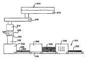
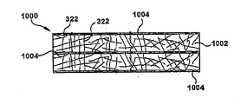
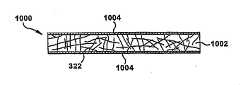
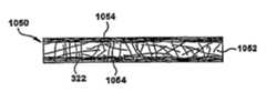
図1A及び図3Aは、繊維状材料からパック300(図3A参照)を形成する連続プロセス又は方法100の第1の例示的な実施形態を示している。方法100のステップを囲む破線101は、当該方法が、以下でより詳しく説明されるように連続的方法であることを示す。方法及びパックは、ガラス繊維に関して説明されるが、当該方法及びパックは、非限定的な例である岩石、スラグ及び玄武岩などの他の鉱物材料から形成される繊維性製品の製造にも同様に適用可能である。 Figures 1A and 3A illustrate a first exemplary embodiment of a continuous process or
図1Aを参照すると、ガラスが溶融される(102)。例えば、図3Aは、溶融装置314を概略的に示している。溶融装置314は、溶融ガラス312をフォアハース316に供給することができる。溶融装置及びフォアハースは当技術分野で知られているので、ここでは説明されない。溶融ガラス312は、所望の化学組成を与えるような割合で組み合わされた様々な原材料から形成することができる。 Referring to FIG. 1A, glass is melted (102). For example, FIG. 3A schematically illustrates a
再び図1Aを参照すると、溶融ガラス312が処理されて、ガラス繊維322が形成される(104)。溶融ガラス312は、繊維322を形成するための様々な異なる方法で処理することができる。例えば、図3Aに示される例において、溶融ガラス312は、フォアハース316から1つ又はそれ以上の回転式紡糸機318へ流れる。回転式紡糸機18は、溶融ガラス312を受け、その後、ガラス繊維322のヴェール320を形成する。より詳細に後述されるように、回転式紡糸機318によって形成されるガラス繊維322は、長く細い。従って、長く細いガラス繊維322を形成するのに十分な、回転式又は別の方式の、任意の所望の紡糸機を使用することができる。図3Aに示される実施形態は1つの回転式紡糸機318を示しているが、任意の所望の数の回転式紡糸機318を使用することができることを認識されたい。別の例示的な実施形態では、繊維322は、火炎吹き飛ばし法によって形成される。 Referring again to FIG. 1A,
長く細い繊維は、多様な異なる形態を取ることができる。例示的な一実施形態において、長く細い繊維は、約0.25インチから約10.0インチまでの範囲の長さ、及び、約9HTから約35HTまでの範囲の直径寸法を有する。HTは、10万分の1インチを表す。例示的な一実施形態において、繊維322は、約1.0インチから約5.0インチまでの範囲の長さ、及び、約14HTから約25HTまでの範囲の直径寸法を有する。例示的な一実施形態において、繊維322は、約3インチの長さ、及び、約16-17HTの平均直径を有する。理論によって拘束されるものではないが、比較的長く細い繊維の使用は、短く太い繊維を有する同様のサイズのパックよりも、優れた遮熱及び遮音性能、並びにより高い引張り強度及び/又はより高い接着強度などの優れた強度特性、を有するパックを有利にもたらすと考えられる。 Long thin fibers can take a variety of different forms. In one exemplary embodiment, the long thin fibers have lengths ranging from about 0.25 inches to about 10.0 inches and diameter dimensions ranging from about 9HT to about 35HT. HT stands for hundred-thousandths of an inch. In one exemplary embodiment, the
繊維がガラス繊維である例示的な実施形態において、バインダレスという用語は、繊維状材料、ウェブ、及び/又はパックが、99%若しくは100%のガラスのみ、又は、99%若しくは100%のガラスに不活性含有物を加えたもの、を含むことを意味する。不活性含有物とは、ガラス繊維を互いに結合しない任意の材料である。例えば、本明細書で説明される例示的なバインダレスの実施形態において、ガラス繊維322は、当該ガラス繊維が形成された後、選択的に潤滑剤で被覆又は部分的に被覆されることができる。例えば、ガラス繊維322は、当該ガラス繊維を互いに結合しない任意の潤滑材料で被覆されることができる。例示的な一実施形態において、潤滑剤は、シロキサン、ジメチルシロキサン及び/又はシランなどのシリコーン化合物とすることができる。潤滑剤はまた、油又は油乳濁液のような他の材料又は材料の組合せとすることができる。油又は油乳濁液は、鉱油若しくは鉱油乳濁液及び/又は植物油若しくは植物油乳濁液とすることができる。 In exemplary embodiments in which the fibers are glass fibers, the term binderless means that the fibrous material, web, and/or pack is 99% or 100% glass only, or 99% or 100% glass. plus inert inclusions. An inert inclusion is any material that does not bind the glass fibers together. For example, in the exemplary binderless embodiments described herein, the
ガラス繊維は、多様な異なる方法で、潤滑剤で被覆又は部分的に被覆することができる。例えば、潤滑剤をガラス繊維322に吹き付けることができる。例示的な実施形態において、潤滑剤は、ガラス繊維322が製造プロセスを通して移動して種々の装置並びに他のガラス繊維と接触する際の当該ガラス繊維322の損傷を防ぐように構成される。潤滑剤はまた、製造プロセスにおける塵埃を減らすのに有用であり得る。選択的な潤滑剤の塗工は、任意の所望の構造、機構又は装置によって正確に制御することができる。 Glass fibers can be coated or partially coated with a lubricant in a variety of different ways. For example, a lubricant can be sprayed onto the
図1Aを参照すると、バインダ又は繊維を互いに結合する他の材料を含まない繊維のウェブ321が形成される(106)。ウェブ321は、多様な異なる方法で形成することができる。図3Aに示す例において、ガラス繊維322は選択的な収集部材324によって集められる。収集部材324は、ガラス繊維322を受ける形状及びサイズにされる。収集部材324は、ガラス繊維322を、例えばウェブ321を形成する成形装置332のような下流の処理ステーションへ移送するためのダクト330へ、振り分ける(divert)ように構成される。他の実施形態において、ガラス繊維322は、運搬機構(図示せず)上に集められてウェブを形成することができる。 Referring to FIG. 1A, a web of
成形装置332は、所望の厚さを有する繊維状材料の連続乾式ウェブ321を形成するように構成することができる。1つの例示的な実施形態において、この出願で開示される乾式ウェブ321は、約0.25インチから約4インチまでの範囲の厚さ、及び、約0.2lb/ft3から約0.6lb/ft3までの範囲の密度を有することができる。1つの例示的な実施形態において、この出願で開示される乾式ウェブ321は、約1インチから約3インチまでの範囲の厚さ、及び、約0.3lb/ft3から約0.5lb/ft3までの範囲の密度を有することができる。1つの例示的な実施形態において、この出願で開示される乾式ウェブ321は、約1.5インチの厚さ、及び、約0.4b/ft3の密度を有することができる。成形装置332は、多様な異なる形態を取ることができる。ガラス繊維の乾式ウェブ321を形成するための任意の構成を使用することができる。Forming
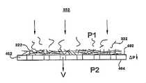
1つの例示的な実施形態において、成形装置332は、成型面と、より高圧又はより低圧の区域と、を有する回転ドラムを含む。図4を参照すると、成形面462の繊維322が収集される側460の圧力P1は、反対側464の圧力P2よりも高い。この圧力損失ΔPが繊維322を成形面462上に集めて乾式ウェブ321を形成させる。1つの例示的な実施形態において、成形面462を横切る圧力損失ΔPは、低圧力であるように制御され、低い面積当り重量のウェブが生成される。例えば、圧力損失ΔPは、約0.5インチ水から30インチ水までとすることができる。この低い圧力損失ΔPを結果としてもたらす、形成中のウェブを通り抜けて移動する空気の速度Vは、毎分1,000フィートまでとすることができる。 In one exemplary embodiment,
低い面積当り重量のウェブ321は、約5乃至約50グラム毎平方フィートの(単位)面積当り重量を有する。低い面積当り重量のウェブは、上記の密度及び厚さの範囲を有することができる。低い面積当り重量のウェブは、約2.5インチから約4インチまでの範囲の厚さ、約1インチから約3インチまでの範囲の厚さ、又は約1.5インチの厚さを有することができる。低い面積当り重量のウェブは、約0.2lb/ft3から約0.6lb/ft3までの範囲の密度、約0.3lb/ft3から約0.5lb/ft3までの範囲の密度、又は約0.4lb/ft3の密度を有することができる。図3Aを参照すると、乾式ウェブ321は、成形装置332から出てくる。1つの例示的な実施形態において、低い面積当り重量のウェブ321は、計測された面積当り重量分布変動係数=シグマ(1標準偏差)/平均値(平均)×100%=0%と40%との間である。例示的な実施形態において、当該重量分布変動係数は、30%未満、20%未満又は10%未満である。1つの例示的な実施形態において、重量分布変動係数は、25%と30%との間、例えば約28%である。1つの例示的な実施形態において、当該重量分布変動係数は、約28%である。当該重量分布変動係数は、大きい例えば6ft×10ftの試料の、複数の小さい例えば2インチ”× 2インチ”の試料面積サイズを、ライトテーブルを用いて計測することにより得られる。A low
例示的な一実施形態では、ウェブ321の繊維322は、当該ウェブの他の方向ではなく当該ウェブの特定の方向に繊維を整列させるべく、操作される。この整列は、様々な異なる態様で達成され得る。例えば、繊維322は、それらが成形装置332によってウェブ321に形成される前、あるいはその時に、延伸され得る。繊維322は、また、ウェブ321が成形装置によって形成された後に、当該ウェブ321を延伸することによって整列され得る。繊維322は、当該繊維を回転ドラム462(図8参照)に適用して薄層化する、及び/または、当該回転ドラムの速度を制御する(典型的には増大する)ことによっても整列され得る。繊維322は、また、ウェブ321を圧縮する、まとめる(bunch)、または、押し潰す(acordian)ことによっても、整列され得る。整列された繊維を有するウェブは、本発明の任意の実施形態において利用され得る。例示的な一実施形態では、繊維の整列は、ウェブ321、ウェブ321から製造される積層ウェブ350、及び、ウェブ321または積層ウェブ350から製造される任意の製品、の強度を増大させる。整列された繊維を有するウェブ321は、本明細書で説明されるように絡合されてもよいし、絡合されなくてもよい。バインダは、本明細書で説明されるように、整列された繊維またはウェブ321に適用され得る。 In one exemplary embodiment,
例示的な一実施形態では、ウェブ321の繊維322は、当該ウェブの幅の方向におけるよりも、及び、当該ウェブの厚さの方向におけるよりも、当該ウェブの走行方向390(図3A参照)においてより繊維を整列させるべく、操作される。この整列は、様々な異なる態様で達成され得る。例えば、繊維322は、それらが成形装置332によってウェブ321に形成される前、あるいはその時に、延伸され得る。繊維322は、また、ウェブ321が成形装置によって形成された後に、当該ウェブ321を走行方向390に延伸することによって整列され得る。積層ウェブ350の繊維は、例えば交差折重ね機構によって積層ウェブ350を延伸することによっても、整列され得る。繊維322は、当該繊維を回転ドラム462(図8参照)に適用して薄層化する、及び/または、当該回転ドラムの速度を制御する(典型的には増大する)ことによっても整列され得る。例えば、ドラム上に収集された整列された繊維の薄いウェブの厚さは、2インチ未満であり得て、例えば0.0625インチと2インチとの間であり、例えば0.125インチと1.5インチとの間であり、例えば0.187インチと1.25インチとの間であり、例えば0.25インチと1インチとの間であり、例えば0.25インチと0.5インチとの間であり、例えば0.25インチであり得る。整列された繊維を有するウェブは、本発明の任意の実施形態において利用され得る。例示的な一実施形態では、繊維の整列は、ウェブ321、ウェブ321から製造される積層ウェブ350、及び、ウェブ321または積層ウェブ350から製造される任意の製品、の引っ張り強度を増大させ、厚さを低減し、及び/または、(単位)面積当り重量を低減する。整列された繊維を有するウェブ321は、本明細書で説明されるように絡合されてもよいし、絡合されなくてもよい。バインダは、本明細書で説明されるように、整列された繊維またはウェブ321に適用され得る。 In an exemplary embodiment, the
例示的な一実施形態では、ウェブ321の繊維322は、当該ウェブの走行方向390におけるよりも、及び、当該ウェブの厚さの方向におけるよりも、当該ウェブの幅の方向においてより繊維を整列させるべく、操作される。この整列は、様々な異なる態様で達成され得る。例えば、繊維322は、それらが成形装置332によってウェブ321に形成される前、あるいはその時に、延伸され得る。繊維322は、また、ウェブ321が成形装置によって形成された後に、当該ウェブ321を幅の方向に延伸することによって整列され得る。繊維は、例えば機械方向390に対して90°でウェブ321の交差折重ねをする交差折重ね機構によってウェブが積層ウェブの幅を規定するべく折重ねられる前に、走行方向390に当該ウェブ321を延伸することによって、積層ウェブ350の幅に関して整列され得る。繊維は、例えば交差折重ね機構によってウェブ321が積層化された後に、当該積層ウェブの幅の方向に積層ウェブ350を延伸することによっても、整列され得る。繊維322は、当該繊維を回転ドラム462(図8参照)に適用して薄層化する、及び/または、当該回転ドラムの速度を制御する(典型的には増大する)ことによっても、ウェブ321の幅の方向または積層ウェブの幅の方向に整列され得る。ウェブの幅の方向に整列された繊維を有するウェブ及び積層ウェブは、本発明の任意の実施形態において利用され得る。例示的な一実施形態では、繊維の整列は、ウェブ321、ウェブ321から製造される積層ウェブ350、及び、ウェブ321または積層ウェブ350から製造される任意の製品、の引っ張り強度を増大させ、厚さを低減し、及び/または、(単位)面積当り重量を低減する。整列された繊維を有するウェブ321は、本明細書で説明されるように絡合されてもよいし、絡合されなくてもよい。バインダは、本明細書で説明されるように、整列された繊維またはウェブ321に適用され得る。 In an exemplary embodiment, the
例示的な一実施形態では、ウェブ321の繊維322は、当該ウェブの走行方向390におけるよりも、及び、当該ウェブの幅の方向におけるよりも、当該ウェブの厚さの方向においてより繊維を整列させるべく、操作される。この整列は、様々な異なる態様で達成され得る。例えば、繊維322は、ウェブ321が成形装置によって形成された後に、ウェブの走行方向390にウェブ321を纏める(bunch)、圧縮する、または、押し潰す(acordian)ことによって、整列され得る。繊維は、ウェブが例えば交差折重ね機構によって折重ねられる前に、走行方向390にウェブ321を纏める(bunch)、圧縮する、または、押し潰す(acordian)ことによっても、積層ウェブ350の厚さに関して整列され得る。繊維は、ウェブ321が積層化された後、積層ウェブの幅の方向、及び/または、走行方向390に積層ウェブ350を纏める(bunch)、圧縮する、または、押し潰す(acordian)ことによっても、整列され得る。ウェブの厚さの方向に整列された繊維を有するウェブ及び積層ウェブは、本発明の任意の実施形態において利用され得る。例示的な一実施形態では、繊維の整列は、ウェブ321、ウェブ321から製造される積層ウェブ350、及び、ウェブ321または積層ウェブ350から製造される任意の製品、の圧縮強度を増大させ、厚さを増大させ、及び/または、(単位)面積当り重量を増大させる。整列された繊維を有するウェブ321は、本明細書で説明されるように絡合されてもよいし、絡合されなくてもよい。バインダは、本明細書で説明されるように、整列された繊維またはウェブ321に適用され得る。 In an exemplary embodiment, the
図1Aに示される例において、ウェブ321又は多重ウェブは、積層されている(108)。例えば、単一のウェブ321を機械方向に折り重ねるか又は機械方向に対して90度で交差折り重ね(cross-lapped)を行って、積層ウェブ350を形成することができる。別の実施形態では、ウェブを複数部分に切断し、当該部分を互いの上に積み重ねて、積層ウェブを形成することができる。さらに別の例示的な実施形態では、1つ又はそれ以上の二重紡糸機318及び成形装置332を、2つ又はそれ以上のウェブが平行に連続的に製造されるように、実装することができる。次いで、平行なウェブを互いの上に積み重ねて、積層ウェブを形成する。 In the example shown in FIG. 1A,
1つの例示的な実施形態において、積層機構332は、コンベア336と連係して機能する折重ね機構又は交差折重ね機構である。コンベア336は、矢印D1で示す機械方向で動くように構成される。折重ね機構又は交差折重ね機構は、連続ウェブ321を受けて、第1のコンベアが機械方向D1に動いているときに連続ウェブの交互層を当該第1のコンベア336上に堆積させるように構成される。当該堆積プロセスにおいて、折重ね機構334が、矢印D1で示す機械方向に交互層を形成することになるか、又は、交差折重ね機構334が、交差機械方向に交互層を形成することになるであろう。付加的なウェブ321を形成し、付加的な折重ね又は交差折重ね機構によって折重ね又は交差折重ねを行って、層の数及び処理能力を増大させることができる。 In one exemplary embodiment, stacking
1つの例示的な実施形態において、交差折重ね機構は、連続ウェブを損傷しないよう、当該連続ウェブ321の移動を正確に制御してコンベア336上に当該連続ウェブを堆積させるように、構成される。交差折重ね機構は、任意の所望の構造を含むことができ、任意の所望の方式で動作するように構成することができる。1つの例示的な実施形態において、交差折重ね機構は、機械方向D1に対して90度で前後に動くように構成されたヘッド(図示せず)を含む。当該実施形態において、可動ヘッドの速度は、交差機械方向の両方向におけるヘッドの動きが実質的に同じになるように調整され、それにより、得られる繊維体(fibrous body)の層の均一性がもたらされるようになっている。例示的な一実施形態では、交差折重ね機構は、コンベア336の中心線に中心を揃えて構成された垂直コンベア(図示せず)を含む。垂直コンベアは、コンベア336の上方でピボット機構により揺動して、コンベア336上に連続ウェブを堆積させるように、さらに構成される。交差折重ね機構の複数の例を前述したが、交差折重ね機構は、他の構造、機構若しくは装置又はそれらの組合せとすることができることを認識されたい。 In one exemplary embodiment, the cross-folding mechanism is configured to precisely control movement of the
積層ウェブ350は、任意の所望の厚さを有することができる。積層ウェブの厚さは、幾つかの変数の関数である。第1に、積層ウェブ350の厚さは、成形装置332によって形成される連続ウェブ321の厚さの関数である。第2に、積層ウェブ350の厚さは、積層機構334が連続ウェブ321の層をコンベア336上に堆積させる速度の関数である。第3に、積層ウェブ334の厚さは、コンベア336の速度の関数である。図示された実施形態において、積層ウェブ350は、約0.1インチから約20.0インチまでの範囲の厚さを有する。例示的な実施形態において、交差折重ね機構334は、1層から60層までを有する積層ウェブ350を形成することができる。選択的に、交差折重ね機構は調節可能とすることができ、それにより交差折重ね機構334が任意の所望の幅を有するパックを形成することが可能になる。特定の実施形態において、パックは、約98.0インチから約236.0インチまでの範囲の全般的な幅を有することができる。 Laminated web 350 can have any desired thickness. Laminated web thickness is a function of several variables. First, the thickness of laminated web 350 is a function of the thickness of
1つの例示的な実施形態において、積層ウェブ350は、図1Aの破線ボックス101によって示された連続プロセスで製造される。紡糸機318によって製造された繊維は、成形装置332に直接送られる(即ち、この繊維は、収集されて梱包され、その後、遠隔の成形装置での使用のために開梱される、というものではない)。ウェブ321は、積層装置352に直接供給される(即ち、ウェブは、形成されて巻き上げられ、その後、遠隔の積層装置352での使用のために巻き出される、というものではない)。連続プロセスの例示的な実施形態において、各々のプロセス(図1Aの成形及び積層)は紡糸プロセスに接続されており、その結果、紡糸機からの繊維は、後の使用のために保管されることなく、他のプロセスによって使用されるようになっている。連続プロセスの別の例示的な実施形態においては、1つ又は複数の紡糸機318が、成形装置332及び積層装置352によって必要とされるよりも大きい処理能力(スループット)を有し得る。そのため、繊維は、プロセスを連続させるために紡糸機318によって成形装置332に必ずしも連続的に供給される必要はない。例えば、紡糸機318は、連続プロセスにおいて同じ工場内で蓄積されて成形装置332に供給される繊維のバッチを製造することができるが、この繊維は、連続プロセスにおいて、圧縮され、出荷され、再開梱されることはない。連続プロセスの別の例として、紡糸機318によって製造された繊維は、成形装置332へ、及び別の成形装置へ、又は他の何らかの使用若しくは製品のために、交互に振り分けることができる。連続プロセスの別の例において、紡糸機318によって製造された繊維の一部分は、連続的に成形装置332へ振り向けられ、繊維の残りの部分は、別の成形装置へ、又は他の何らかの使用若しくは製品のために振り向けられる。 In one exemplary embodiment, laminated web 350 is manufactured in a continuous process indicated by dashed
図3Eは、図3A-図3Dに示すいずれかの例において、繊維322を蓄積機390により収集することができることを示す。矢印392は、繊維322が、蓄積機390によって、制御された方式で成形装置332に供給されることを示す。繊維322は、成形装置332に供給される前に、繊維を冷やすために所定時間にわたって蓄積機390内に滞留することができる。1つの例示的な実施形態において、繊維322は、繊維322が蓄積機390に供給されるのと同じ速度で、蓄積機390によって成形装置332に供給される。それゆえ、この例示的な実施形態において、繊維が蓄積機内で滞留して冷える時間は、蓄積機内の繊維322の量によって決定される。この例において、滞留時間は、蓄積機内の繊維の量を、繊維が蓄積機によって成形装置332に供給される速度で割った値となる。別の例示的な実施形態において、蓄積機390は、繊維の供給を選択的に開始及び停止することができ、及び/又は、繊維を供給する速度を調節することができる。 FIG. 3E shows that
図3Fは、図3A-3Dに示すいずれかの例において、繊維322を分流(diverting)機構398によって成形ステーション332と第2の成形ステーション332’との間で選択的に振り分けることができることを示す。1つの例示的な実施形態において、図3A-3Dに示す実施形態は、蓄積機390と分流機構398の両方を有することができる。 FIG. 3F illustrates that in any of the examples shown in FIGS. 3A-3D,
1つの例示的な実施形態において、ウェブ321は、比較的厚く、且つ、低い面積当り重量を有するが、それでもなお連続プロセスは高い処理能力を有し、紡糸機によって製造される全ての繊維がウェブを作るために使用される。例えば、ウェブ321の単一層は、約5乃至約50グラム毎平方フィートの面積当り重量を有することができる。低い面積当り重量のウェブは、前述の密度及び厚さの範囲を有することができる。高生産量連続プロセスは、約750lbs/hrと1500lbs/hrとの間、例えば、少なくとも900lbs/hr又は少なくとも1250lbs/hrで製造することができる。積層ウェブ350は、多様な異なる用途に使用することができる。 In one exemplary embodiment,
図1B及び図3Bは、バインダを使用せずに繊維状材料からパック300(図3B参照)を形成する方法150の第2の例示的な実施形態を示す。方法150のステップを囲む破線151は、この方法が連続的方法であることを示す。図1Bを参照すると、ガラスが溶融される(102)。ガラスは、図3Aに関して前述したように、溶融することができる。溶融ガラス312を処理して、ガラス繊維322を形成する(104)。溶融ガラス312は、図3Aに関して前述したように処理されて、繊維322を形成することができる。バインダ又は繊維を互いに結合する他の材料を含まない繊維のウェブ321が形成される(106)。ウェブ321は、図3Aに関して前述したように形成することができる。 Figures 1B and 3B illustrate a second exemplary embodiment of a
図1Bを参照すると、ウェブ321の繊維322が機械的に絡合されて(202)、絡合ウェブ352(図3B参照)が形成される。図3Bを参照すると、ウェブ321の繊維は、ニードリング装置のような絡合機構345によって機械的に絡合することができる。絡合機構345は、ウェブ321の個々の繊維322を絡合するように構成される。ガラス繊維を絡合することで、ウェブの繊維を互いに束縛する。絡合は、ウェブの引張り強度及び剪断強度などの機械的特性を向上させる。図示した実施形態において、絡合機構345はニードリング機構である。他の実施形態において、絡合機構345は、非限定的な例であるスティッチング機構を含む、他の構造、機構若しくは装置又はそれらの組合せを含むことができる。 Referring to FIG. 1B,
図17乃至図24を参照して、絡合装置345は、様々な異なる形態を有し得る。図17乃至図24は、現存する絡合装置の幾つかの例を図示している。図17は、回転タッカー1702を図示している。図18は、下向き動作ニードルルーム1802を図示している。図19は、上向き動作ニードルルーム1902を図示している。図20は、ダブル下向き動作ニードルルーム2002を図示している。図21は、ダブル上向き動作ニードルルーム2102を図示している。図22は、シングル上向き動作及びシングル下向き動作ニードルルーム2202を図示している。図23は、ダブル上向き動作及びダブル下向き動作ニードルルーム2202を図示している。図24は、楕円ニードルルームを図示している。楕円ニードルルームは、図18乃至図23に図示された形態のいずれにも適合し得て、楕円動作または他の線形動作を伴う。 17-24, the
例示的な一実施形態において、絡合装置345は、複数の絡合ユニットないしルーム(織機)を有する。複数の絡合ユニットないしルームは、同一形態であってもよいし、異なる形態であってもよい。任意の数の絡合ユニットないしルームの数が含まれ得る。例示的な一実施形態では、絡合装置345は、ウェブ321及び/または積層ウェブ350を、上方から及び/または下方から任意の回数で任意の順序で絡合するように構成され得る。例えば、絡合装置345は、図17乃至図24に図示された絡合装置の2以上の任意の順序での任意の組合せを有し得る。 In one exemplary embodiment, the
例示的な幾つかの実施形態において、絡合装置は、ウェブの他側よりもウェブ321の一側において、より多い繊維の絡合を提供し、ウェブの異なる領域、例えばウェブ321の異なる深さ、及び/または、ウェブの異なる側、で絡合の異なるタイプを提供する。例示的な一実施形態では、ウェブ321の繊維322は、選択的に、当該繊維または当該繊維の部分を、ウェブの幅の方向及びウェブの厚さの方向におけるよりもウェブの走行方向390においてより整列させるべく、絡合装置によって操作される。 In some exemplary embodiments, the entangling device provides more fiber entanglement on one side of the
図25に図示された例示的な一実施形態では、絡合装置345は、2つのニードルルームを有している。当該2つのニードルルームは、図示のような「2回下向き」形態2002であり得て、両方のルームが、ウェブ321上に押圧し得るか(図21参照)、あるいは、1つのルームがウェブ321に上から作用して他のルームが下からウェブに作用し得る(図22参照)。図25を参照して、図示の実施形態では、ウェブ321は絡合装置345に入って、より薄い絡合ウェブ352として絡合装置345を得る。 In one exemplary embodiment illustrated in FIG. 25, the
図26に図示された例示的な一実施形態では、絡合装置345は、2つの異なるタイプの絡合ユニットを有している。当該異なる絡合ユニットは、様々な異なる形態を有し得る(例えば、図17乃至図24参照)。例えば、第1絡合ユニットは、回転タッカー1702であり得るし、ウェブの上面と底面との両方でウェブに作用する他の絡合装置であり得る。第2絡合ユニットは、ニードルルーム1802であり得るし、ウェブ321の片側に作用する他の絡合装置であり得る。図示の絡合装置は、上面からウェブに作用するが、底面からウェブに作用するように構成されてもよい。絡合ユニット1702、1802の順序は、ウェブの両側に作用する絡合ユニット1702の上流にウェブの片側のみに作用する絡合ユニット1802があるというように、反転され得る。図26を参照して、図示の実施形態では、ウェブ321は絡合装置に入って、中間厚さウェブ2610に絡合される。中間厚さウェブ2610は、更に、第2絡合ユニットによって絡合されて、薄い絡合ウェブ352.0が形成される。 In one exemplary embodiment illustrated in FIG. 26, the
例示的な一実施形態では、絡合装置は、矢印1750によって示された方向にウェブ321が前進するのと同期して、または略同期して、前進するように構成される。例えば、絡合ユニットは、ウェブ321との係合中、矢印390の方向に前進し得て、ウェブから離れる時、元の位置に戻る。回転タッカー1702及び/または楕円ルーム2402の回転層度は、ウェブ321の速度に基づいて、当該ウェブ321の速度との当該絡合装置の同期ないし略同期を提供するべく、選択され得る。 In one exemplary embodiment, the entanglement device is configured to advance synchronously or substantially synchronously with the advancement of
本願の実施形態の全てに関して、ウェブ321は、図17及び図18の実施形態の機械的な絡合前に積層化され得る。図18の実施形態において、ウェブ321は、絡合装置1802及び絡合装置1804の両方の前に、及び/または、絡合装置1802、1804の間で、積層化され得る。 For all of the embodiments of this application, the
絡合ウェブ352は、任意の所望の厚さを有することができる。絡合ウェブの厚さは、成形装置332によって形成される連続ウェブ321の厚さと、絡合機構345による連続ウェブ321の圧縮量との関数である。例示的な実施形態において、絡合ウェブ352は、約0.1インチから約2.0インチまでの範囲の厚さを有する。例示的な実施形態において、絡合ウェブ352は、約0.5インチから約1.75インチまでの範囲の厚さを有する。例えば、1つの例示的な実施形態において、絡合ウェブの厚さは約1/2”(インチ)である。
1つの例示的な実施形態において、絡合ウェブ352は、連続プロセス151で製造される。紡糸機318によって製造された繊維は、成形装置332に直接送られる(即ち、この繊維は、収集されて梱包され、その後、遠隔の成形装置での使用のために開梱される、というものではない)。ウェブ321は、絡合装置345に直接供給される(即ち、ウェブは、形成されて巻き上げられ、その後、遠隔の絡合装置345での使用のために巻き出される、というものではない)。絡合ウェブ352は、多様な異なる用途に使用することができる。連続プロセスの例示的な実施形態において、各々のプロセス(図1Bの成形及び絡合)は紡糸プロセスに接続されており、その結果、紡糸機からの繊維は、後の使用のために保管されることなく、他のプロセスによって使用されるようになっている。連続プロセスの別の例示的な実施形態において、1つ又は複数の紡糸機318は、成形装置332及び/又は絡合装置345によって必要とされるよりも大きい処理能力を有し得る。それゆえ、繊維は、プロセスを連続させるために紡糸機318によって成形装置332に必ずしも連続的に供給される必要はない。例えば、紡糸機318は、連続プロセスにおいて同じ工場内で蓄積されて成形装置332に供給される繊維のバッチを製造することができるが、この繊維は、連続プロセスにおいて、圧縮され、出荷され、再開梱されることはない。連続プロセスの別の例として、紡糸機318によって製造された繊維は、成形装置332へ、及び別の成形装置へ、又は他の何らかの使用若しくは製品用に、交互に振り分けることができる。連続プロセスの別の例において、紡糸機318によって製造された繊維の一部分は、連続的に成形装置332へ振り向けられ、繊維の残りの部分は、別の成形装置へ、又は他の何らかの使用若しくは製品用に振り向けられる。 In one exemplary embodiment,
図3Dは、単一層高密度パック300を形成するための、図3Bに示した実施形態と類似の装置の例示的な実施形態を示す。例えば、図3Dに示す実施形態は、図3Bに示す実施形態によって製造される最高密度のパックよりも密度の高いパック300を製造することができる。図3Dの装置は、図3Bの実施形態に対応するが、圧縮機構375が成形ステーション332と絡合機構345との間に設けられる点、及び/又は、絡合機構345が圧縮機構を含む点で異なる。圧縮機構375は、ウェブ321が絡合機構345に送られる前に矢印377で示されるようにウェブ321を圧縮し、及び/又は、ウェブ321は圧縮機構の入口で圧縮される。形成される絡合ウェブ352は、高密度を有する。圧縮機構は多様な異なる形態を取ることができる。圧縮機構345の例としては、それらに限定されないが、ローラ、ベルト、回転タッカー、付加的なニードリング機構、絡合ウェブ352と反対側のベルトの側に負圧をかけた穴あきベルト(図4に示す同様の例を参照)、列挙した圧縮機構の任意の組合せを含む任意の機構、列挙した圧縮機構の任意の特徴の任意の組合せを含む任意の機構、などが挙げられる。ウェブを圧縮するための任意の構成を使用することができる。絡合機構345が圧縮機構を含むとき、圧縮機構375は、図3Dに示す単一層高密度パック300の実施形態において省略することができる。圧縮機構375及び/又は絡合機構345によって行われる圧縮は、圧縮及び/又はニードリングの任意の組合せとすることができ、それは、繊維を絡合させることに加えてパックを圧縮する。高密度パックを製造するための圧縮及びニードリングの順序の例としては、それらに限定されないが、ローラによる圧縮とその後のニードリング、2回のニードリング、ローラによる圧縮とその後の2回のニードリング、3回のニードリング、予備ニードリング-上からのニードリング-下からのニードリング、予備ニードリング-下からのニードリング-上からのニードリング、ローラによる圧縮-上からのニードリング-下からのニードリング、及び、ローラによる圧縮-下からのニードリング-上からのニードリング、が挙げられる。 FIG. 3D shows an exemplary embodiment of an apparatus similar to the embodiment shown in FIG. 3B for forming a single layer
図3Dの高密度絡合ウェブ352は、任意の所望の厚さを有することができる。絡合ウェブの厚さは、成形装置332によって形成される連続ウェブ321の厚さと、圧縮機構375及び絡合機構345による連続ウェブ321の圧縮量と、の関数である。例示的な実施形態において、図3Dの高密度絡合ウェブ352は、約0.1インチから約5インチまでの範囲の厚さを有する。例示的な実施形態において、高密度絡合ウェブ352は、約0.250インチから約3.0インチまでの範囲の厚さを有する。例示的な実施形態において、高密度絡合ウェブは、0.4lb/ft3から約12lb/ft3までの範囲の密度を有する。1つの例示的な実施形態において、図3Dの高密度絡合ウェブ352は、図3Bに関して説明したのと同じ方法で、連続プロセスで製造される。Dense
図1C及び図3Cは、バインダを使用せずに繊維状材料からパック370(図3C参照)を形成する方法170の別の例示的な実施形態を示している。図1Cを参照すると、ガラスが溶融される(102)。方法170のステップを囲む破線171は、この方法が連続的方法であることを示している。ガラスは、図3Aに関して前述したように、溶融することができる。再び図1Cを参照すると、溶融ガラス312が処理されて、ガラス繊維322が形成される(104)。溶融ガラス312は、図3Aに関して前述したように処理されて、繊維322を形成することができる。図1Cを参照すると、バインダ又は繊維を互いに結合する他の材料を含まない繊維のウェブ321が形成される(106)。ウェブ321は、図3Aに関して前述したように形成することができる。図1Cを参照すると、ウェブ321又は複数のウェブが積層される(108)。ウェブ321又は多重ウェブは、図3Aに関して前述したように積層することができる。図1Cを参照すると、積層ウェブ350の繊維322が機械的に絡合されて(302)、積層ウェブの絡合パック370が形成される。 Figures 1C and 3C illustrate another exemplary embodiment of a
図3Cを参照すると、積層ウェブ350の繊維は、ニードリング装置のような絡合機構345によって機械的に絡合することができる。絡合機構345は、積層ウェブの層を形成する個々の繊維322を絡合するように構成される。ガラス繊維322を絡合することで、積層ウェブ350の繊維を互いに束縛してパックが形成される。機械的絡合は、引張り強度及び剪断強度などの機械的特性を向上させる。図示した実施形態において、絡合機構345はニードリング機構である。他の実施形態においては、絡合機構345は、非限定的な例としてスティッチング機構を含む、他の構造、機構若しくは装置又はそれらの組合せを含むことができる。 Referring to FIG. 3C, the fibers of laminated web 350 can be mechanically entangled by an
積層ウェブ350の絡合パック370は、任意の所望の厚さを有することができる。絡合パックの厚さは、幾つかの変数の関数である。第1に、絡合パックの厚さは、成形装置332によって形成される連続ウェブ321の厚さの関数である。第2に、絡合パック370の厚さは、折重ね又は交差折重ね機構334が連続ウェブ321の層をコンベア336上に堆積させる速度の関数である。第3に、絡合パック370の厚さは、コンベア336の速度の関数である。第4に、絡合パック370の厚さは、絡合機構345による積層ウェブ350の圧縮量の関数である。絡合パック370は、約0.1インチから約20.0インチまでの範囲の厚さを有することができる。例示的な実施形態において、絡合パック370は、1層から60層までを有することができる。各々の絡合ウェブ層352は、0.1乃至2インチ厚にすることができる。例えば、各々の絡合ウェブ層は、約0.5インチ厚にすることができる。 The entangled packs 370 of the laminated web 350 can have any desired thickness. The thickness of the entanglement pack is a function of several variables. First, the thickness of the entangled pack is a function of the thickness of the
1つの例示的な実施形態において、絡合パック370は、連続プロセスで製造される。紡糸機318によって製造された繊維は、成形装置332に直接送られる(即ち、この繊維は、収集されて梱包され、その後、遠隔の成形装置での使用のために開梱される、というものではない)。ウェブ321は、積層装置352に直接供給される(即ち、ウェブは、形成されて巻き上げられ、その後、遠隔の積層装置352での使用のために巻き出される、というものではない)。積層ウェブ350は、絡合装置345に直接供給される(即ち、積層ウェブは、形成されて巻き上げられ、その後、遠隔の絡合装置345での使用のために巻き出される、というものではない)。連続プロセスの例示的な実施形態において、各々のプロセス(図1Cの成形、積層及び絡合)は紡糸プロセスに接続されており、その結果、紡糸機からの繊維は、後の使用のために保管されることなく、他のプロセスによって使用されるようになっている。連続プロセスの別の例示的な実施形態において、1つ又は複数の紡糸機318は、成形装置332、積層装置352、及び/又は絡合装置によって必要とされるよりも大きい処理能力を有し得る。そのため、繊維は、プロセスを連続させるために紡糸機318によって成形装置332に必ずしも連続的に供給される必要はない。例えば、紡糸機318は、連続プロセスにおいて同じ工場内で蓄積されて成形装置332に供給される繊維のバッチを製造することができるが、この繊維は、連続プロセスにおいて、圧縮され、出荷され、再開梱されることはない。連続プロセスの別の例として、紡糸機318によって製造された繊維は、成形装置332へ、及び別の成形装置へ、又は他の何らかの使用若しくは製品用に、交互に振り分けることができる。連続プロセスの別の例において、紡糸機318によって製造された繊維の一部分は、連続的に成形装置332に振り向けられ、繊維の残りの部分は、別の成形装置へ、又は他の何らかの使用若しくは製品用に振り向けられる。 In one exemplary embodiment, entangled pack 370 is manufactured in a continuous process. Fibers produced by
例示的な実施形態において、積層ウェブの絡合パック370は、比較的厚く、且つ、低い面積当り重量を有するウェブ321又は複数のウェブから作られるが、それでもなお連続プロセスは高い処理能力を有し、紡糸機によって製造される全ての繊維が絡合パックを作るために使用される。例えば、ウェブ321の単一層が、前述の面積当り重量、厚さ、及び密度を有することができる。高生産量連続プロセスは、約750lbs/hrと1500lbs/hrとの間、例えば、少なくとも900lbs/hr又は少なくとも1250lbs/hrを製造することができる。例示的な実施形態において、連続プロセスの高いウェブ処理能力とニードリングのような機械的絡合との組合せは、ウェブの折重ね又は交差折重ねのようなウェブ321の積層によって容易になる。ウェブ321を積層することにより、積層装置を通って移動する材料の直線速度は、ウェブが形成される速度より遅くなる。例えば、連続プロセスにおいて、2層ウェブは、ウェブが形成される速度の1/2の速度で絡合装置345内を移動することになる(3層の場合は1/3の速度、等)。この速度の低減が、高処理量で低い面積当り重量のウェブ321が形成され、複数層の機械的に絡合されたパック370に変換される、という連続プロセスを可能にする。積層ウェブの絡合パック370は、多様な異なる用途に使用することができる。 In an exemplary embodiment, the entangled pack 370 of laminated webs is made from a
例示的な実施形態において、長く細い繊維の積層及び絡合は、強いウェブ370を結果としてもたらす。例えば、この出願において説明される長く細いガラス繊維の絡合は、高引張り強度及び高接着強度を有する積層絡合ウェブを結果としてもたらす。引張り強度は、ウェブ370が当該ウェブの長さ又は幅の方向に引っ張られたときのウェブ370の強度である。接着強度は、ウェブ370が当該ウェブの厚さ方向に引き離されるときのウェブの強度である。 In an exemplary embodiment, the lamination and entanglement of long fine fibers results in a strong web 370 . For example, the entanglement of long thin glass fibers described in this application results in a laminated entangled web with high tensile strength and high bond strength. Tensile strength is the strength of web 370 when web 370 is pulled in the length or width direction of the web. Bond strength is the strength of web 370 as it is pulled apart through the thickness of the web.
引張り強度及び接着強度は、多様な異なる方法で試験することができる。1つの例示的な実施形態において、インストロン(Instron)機などの機械が、ウェブ370を一定速度(後述する例においては12インチ毎秒)で引っ張り、ウェブを引き離すのに要した力の量を計測する。ウェブを引き離すのに要した力が、ウェブが裂けるか又は損傷するまでにウェブに加えられたピーク力を含めて記録される。 Tensile strength and adhesive strength can be tested in a variety of different ways. In one exemplary embodiment, a machine such as an Instron machine pulls the web 370 at a constant speed (12 inches per second in the example described below) and measures the amount of force required to pull the web apart. do. The force required to pull the web apart is recorded, including the peak force applied to the web until it tears or fails.
引張り強度を試験する1つの方法において、長さ方向の引張り強度は、ウェブの端部をウェブの幅に沿って固定し、ウェブ370をウェブの長さに沿って機械により一定速度(以下に示す例では12インチ毎秒)で引っ張り、ウェブの長さ方向に加えられたピーク力を記録することによって計測される。幅方向の引張り強度は、ウェブの側部をウェブの幅に沿って固定し、ウェブ370をウェブの幅に沿って一定速度(以下に示す例では12インチ毎秒)で引っ張り、加えられたピーク力を記録することによって計測される。長さ方向の引張り強度と幅方向の引張り強度との平均を取って、試料の引張り強度が決定される。 In one method of testing tensile strength, longitudinal tensile strength is measured by fixing the ends of the web along the width of the web and running the web 370 along the length of the web at a constant speed (shown below) by a machine. 12 inches per second in the example) and recorded the peak force applied along the length of the web. The transverse pull strength is determined by fixing the sides of the web along the width of the web and pulling the web 370 along the width of the web at a constant velocity (12 inches per second in the example shown below), the applied peak force is measured by recording The tensile strength of the sample is determined by taking the average of the longitudinal tensile strength and the transverse tensile strength.
接着強度を試験する1つの方法において、所定のサイズ(以下に示す例では6”×6”)の試料が準備される。試料の各側面が、基板に例えば糊付けにより接着される。試料の両側の基板を機械により一定速度(以下に示す例では12インチ毎秒)で引き離し、加えられたピーク力を記録する。加えられたピーク力を試料の面積(以下に示す例では6”×6”)で割ると、力/面積の単位で接着強度が与えられる。 In one method of testing bond strength, a sample of predetermined size (6″×6″ in the example shown below) is prepared. Each side of the sample is adhered to the substrate, eg by gluing. The substrates on both sides of the sample are mechanically pulled apart at a constant rate (12 inches per second in the example shown below) and the peak force applied is recorded. Dividing the peak force applied by the area of the sample (6″×6″ in the example shown below) gives the bond strength in units of force/area.
以下の例は、層状絡合ウェブ370の強度の増大を示すために提示される。これらの例において、バインダは全く含まれていない。即ち、水性バインダも乾式バインダも含まれていない。これらの例は、特許請求の範囲において明示的に述べられない限り、本発明の範囲を限定するものではない。4層、6層、及び8層を有する層状絡合ウェブの例が提示される。しかし、層状絡合ウェブ370には、任意の数の層を設けることができる。層状絡合ウェブ370試料の長さ、幅、厚さ、折重ねの数、及び重量は、ウェブ370の用途に応じて変えることができる。図3Dに示す稠密な単一層の実施形態において、単一層高密度パック300は、以下の6つの段落における同じ厚さの例よりも高い、例えば2倍又はそれ以上高い、平方フィート当りの重量を有することができる。 The following example is presented to demonstrate the increased strength of the layered entangled web 370. In these examples, no binder is included. That is, neither aqueous binders nor dry binders are included. These examples do not limit the scope of the invention unless explicitly stated in the claims. Examples of layered entangled webs having 4, 6, and 8 layers are presented. However, the layered entangled web 370 can be provided with any number of layers. The length, width, thickness, number of folds, and weight of a layered entangled web 370 sample can vary depending on the web 370 application. In the dense single layer embodiment shown in FIG. 3D, the single layer
1つの例示的な実施形態において、ウェブ370の6インチ×12インチの試料は、複数層、例えば2つの折重ね(即ち、4層)を有し、0.5インチ厚と2.0インチ厚の間であり、0.1lbs/sqftと0.3lbs/sqftとの間の重量毎平方フィートを有し、3lbfより大きい引張り強度を有し、40lbf/lbmより大きい、例えば約40乃至約120lbf/lbmの引張り強度対重量の比を有する。例示的な一実施形態において、この試料の接着強度は0.1lbs/平方ftより大きい。
例示的な一実施形態において、本段落で説明される試料の引張り強度は5lbfより大きい。例示的な一実施形態において、本段落で説明される試料の引張り強度は7.5lbfより大きい。例示的な一実施形態において、本段落で説明される試料の引張り強度は10lbfより大きい。例示的な一実施形態において、本段落で説明される試料の引張り強度は12.5lbfより大きい。例示的な一実施形態において、本段落で説明される試料の引張り強度は13.75lbfより大きい。例示的な一実施形態において、本段落で説明される試料の引張り強度は3lbfと15lbfとの間である。
例示的な一実施形態において、本段落で説明される試料の接着強度は2lbs/sqftより大きい。例示的な一実施形態において、本段落で説明される試料の接着強度は5lbs/sqftより大きい。例示的な一実施形態において、本段落で説明される試料の接着強度は10lbs/sqftより大きい。例示的な一実施形態において、本段落で説明される試料の接着強度は15lbs/sqftより大きい。例示的な一実施形態において、本段落で説明される試料の接着強度は20lbs/sqftより大きい。
例示的な一実施形態において、本段落で説明される試料の引張り強度は5lbfより大きく、接着強度は2lbs/sqftより大きい。例示的な一実施形態において、本段落で説明される試料の引張り強度は7.5lbfより大きく、接着強度は7.5lbs/sqftより大きい。例示的な一実施形態において、本段落で説明される試料の引張り強度は10lbfより大きく、接着強度は10lbs/sqftより大きい。例示的な一実施形態において、本段落で説明される試料の引張り強度は12.5lbfより大きく、接着強度は15lbs/sqftより大きい。例示的な一実施形態において、本段落で説明される試料の引張り強度は13.75lbfより大きく、接着強度は20lbs/sqftより大きい。例示的な一実施形態において、本段落で説明される試料の引張り強度は3lbfと15lbfとの間であり、接着強度は0.3lbs/sqftと30lbs/sqftとの間である。In one exemplary embodiment, a 6 inch by 12 inch sample of web 370 has multiple layers, such as two folds (i.e., 4 layers), and is 0.5 inch thick and 2.0 inch thick. has a weight per square foot of between 0.1 lbs/sqft and 0.3 lbs/sqft, has a tensile strength of greater than 3 lbf, and has a tensile strength of greater than 40 lbf/lbm, such as from about 40 to about 120 lbf/ It has a tensile strength to weight ratio of lbm. In one exemplary embodiment, the bond strength of this sample is greater than 0.1 lbs/sq.ft.
In one exemplary embodiment, the tensile strength of the samples described in this paragraph is greater than 5 lbf. In one exemplary embodiment, the tensile strength of the samples described in this paragraph is greater than 7.5 lbf. In one exemplary embodiment, the tensile strength of the samples described in this paragraph is greater than 10 lbf. In one exemplary embodiment, the tensile strength of the samples described in this paragraph is greater than 12.5 lbf. In one exemplary embodiment, the tensile strength of the samples described in this paragraph is greater than 13.75 lbf. In one exemplary embodiment, the tensile strength of the samples described in this paragraph is between 3 lbf and 15 lbf.
In one exemplary embodiment, the bond strength of the samples described in this paragraph is greater than 2 lbs/sqft. In one exemplary embodiment, the bond strength of the samples described in this paragraph is greater than 5 lbs/sqft. In one exemplary embodiment, the bond strength of the samples described in this paragraph is greater than 10 lbs/sqft. In one exemplary embodiment, the bond strength of the samples described in this paragraph is greater than 15 lbs/sqft. In one exemplary embodiment, the bond strength of the samples described in this paragraph is greater than 20 lbs/sqft.
In one exemplary embodiment, the tensile strength of the samples described in this paragraph is greater than 5 lbf and the adhesive strength is greater than 2 lbs/sqft. In one exemplary embodiment, the tensile strength of the samples described in this paragraph is greater than 7.5 lbf and the adhesive strength is greater than 7.5 lbs/sqft. In one exemplary embodiment, the tensile strength of the samples described in this paragraph is greater than 10 lbf and the adhesive strength is greater than 10 lbs/sqft. In one exemplary embodiment, the tensile strength of the samples described in this paragraph is greater than 12.5 lbf and the adhesive strength is greater than 15 lbs/sqft. In one exemplary embodiment, the tensile strength of the samples described in this paragraph is greater than 13.75 lbf and the bond strength is greater than 20 lbs/sqft. In one exemplary embodiment, the tensile strength of the samples described in this paragraph is between 3 lbf and 15 lbf and the bond strength is between 0.3 lbs/sqft and 30 lbs/sqft.
1つの例示的な一実施形態において、ウェブ370の6インチ×12インチの試料は複数層、例えば2つの折重ね(即ち、4層)を有し、0.5インチ厚と1.75インチ厚との間であり、0.12lbs/sqftと0.27lbs/sqftの間の重量毎平方フィートを有し、3lbfより大きい引張り強度を有し、40lbf/lbmより大きい、例えば約40乃至約120lbf/lbmの引張り強度対重量の比、並びに1lb/sqftより大きい接着強度を有する。
例示的な一実施形態において、本段落で説明される試料の引張り強度は5lbfより大きい。例示的な一実施形態において、本段落で説明される試料の引張り強度は7.5lbfより大きい。例示的な一実施形態において、本段落で説明される試料の引張り強度は10lbfより大きい。例示的な一実施形態において、本段落で説明される試料の引張り強度は12.5lbfより大きい。例示的な一実施形態において、本段落で説明される試料の引張り強度は13.75lbfより大きい。例示的な一実施形態において、本段落で説明される試料の引張り強度は、3lbfと15lbfとの間である。
例示的な一実施形態において、本段落で説明される試料の接着強度は2lbs/sqftより大きい。例示的な一実施形態において、本段落で説明される試料の接着強度は5lbs/sqftより大きい。例示的な一実施形態において、本段落で説明される試料の接着強度は10lbs/sqftより大きい。例示的な一実施形態において、本段落で説明される試料の接着強度は15lbs/sqftより大きい。例示的な一実施形態において、本段落で説明される試料の接着強度は20lbs/sqftより大きい。
例示的な一実施形態において、本段落で説明される試料の引張り強度は5lbfより大きく、接着強度は2lbs/sqftより大きい。例示的な一実施形態において、本段落で説明される試料の引張り強度は7.5lbfより大きく、接着強度は7.5lbs/sqftより大きい。例示的な一実施形態において、本段落で説明される試料の引張り強度は10lbfより大きく、接着強度は10lbs/sqftより大きい。例示的な一実施形態において、本段落で説明される試料の引張り強度は12.5lbfより大きく、接着強度は15lbs/sqftより大きい。例示的な一実施形態において、本段落で説明される試料の引張り強度は13.75lbfより大きく、接着強度は20lbs/sqftより大きい。例示的な一実施形態において、本段落で説明される試料の引張り強度は3lbfと15lbfの間であり、接着強度は0.3lbs/sqftと30lbs/sqftの間である。In one exemplary embodiment, a 6 inch by 12 inch sample of web 370 has multiple layers, such as two folds (i.e., four layers), and is 0.5 inch thick and 1.75 inch thick. having a weight per square foot of between 0.12 lbs/sqft and 0.27 lbs/sqft, having a tensile strength greater than 3 lbf, and having a tensile strength greater than 40 lbf/lbm, such as from about 40 to about 120 lbf/ It has a tensile strength to weight ratio of lbm and an adhesive strength of greater than 1 lb/sqft.
In one exemplary embodiment, the tensile strength of the samples described in this paragraph is greater than 5 lbf. In one exemplary embodiment, the tensile strength of the samples described in this paragraph is greater than 7.5 lbf. In one exemplary embodiment, the tensile strength of the samples described in this paragraph is greater than 10 lbf. In one exemplary embodiment, the tensile strength of the samples described in this paragraph is greater than 12.5 lbf. In one exemplary embodiment, the tensile strength of the samples described in this paragraph is greater than 13.75 lbf. In one exemplary embodiment, the tensile strength of the samples described in this paragraph is between 3 lbf and 15 lbf.
In one exemplary embodiment, the bond strength of the samples described in this paragraph is greater than 2 lbs/sqft. In one exemplary embodiment, the bond strength of the samples described in this paragraph is greater than 5 lbs/sqft. In one exemplary embodiment, the bond strength of the samples described in this paragraph is greater than 10 lbs/sqft. In one exemplary embodiment, the bond strength of the samples described in this paragraph is greater than 15 lbs/sqft. In one exemplary embodiment, the bond strength of the samples described in this paragraph is greater than 20 lbs/sqft.
In one exemplary embodiment, the tensile strength of the samples described in this paragraph is greater than 5 lbf and the adhesive strength is greater than 2 lbs/sqft. In one exemplary embodiment, the tensile strength of the samples described in this paragraph is greater than 7.5 lbf and the adhesive strength is greater than 7.5 lbs/sqft. In one exemplary embodiment, the tensile strength of the samples described in this paragraph is greater than 10 lbf and the adhesive strength is greater than 10 lbs/sqft. In one exemplary embodiment, the tensile strength of the samples described in this paragraph is greater than 12.5 lbf and the adhesive strength is greater than 15 lbs/sqft. In one exemplary embodiment, the tensile strength of the samples described in this paragraph is greater than 13.75 lbf and the bond strength is greater than 20 lbs/sqft. In one exemplary embodiment, the tensile strength of the samples described in this paragraph is between 3 lbf and 15 lbf and the adhesive strength is between 0.3 lbs/sqft and 30 lbs/sqft.
1つの例示的な一実施形態において、ウェブ370の6インチ×12インチの試料は複数層、例えば2つの折重ね(即ち、4層)を有し、0.5インチ厚と1.25インチ厚の間であり、0.2lbs/sqftと0.3lbs/sqftとの間の重量毎平方フィートを有し、10lbfより大きい引張り強度を有し、75lbf/lbmより大きい、例えば約75乃至約120lbf/lbmの引張り強度対重量の比を有する。
例示的な一実施形態において、本段落で説明される試料の引張り強度は12.5lbfより大きい。例示的な一実施形態において、本段落で説明される試料の引張り強度は13.75lbfより大きい。例示的な一実施形態において、本段落で説明される試料の引張り強度は3lbfと15lbfとの間である。例示的な一実施形態において、本段落で説明される試料の接着強度は3lbs/sqftより大きい。例示的な一実施形態において、本段落で説明される試料の接着強度は10lbs/sqftより大きい。例示的な一実施形態において、本段落で説明される試料の接着強度は15lbs/sqftより大きい。
例示的な一実施形態において、本段落で説明される試料の引張り強度は10lbfより大きく、接着強度は3lbs/sqftより大きい。例示的な一実施形態において、本段落で説明される試料の引張り強度は12.5lbfより大きく、接着強度は10lbs/sqftより大きい。例示的な一実施形態において、本段落で説明される試料の引張り強度は13.75lbfより大きく、接着強度は15lbs/sqftより大きい。In one exemplary embodiment, a 6 inch by 12 inch sample of web 370 has multiple layers, such as two folds (i.e., four layers), and is 0.5 inch thick and 1.25 inch thick. has a weight per square foot of between 0.2 lbs/sqft and 0.3 lbs/sqft, has a tensile strength of greater than 10 lbf, and has a tensile strength of greater than 75 lbf/lbm, such as from about 75 to about 120 lbf/ It has a tensile strength to weight ratio of lbm.
In one exemplary embodiment, the tensile strength of the samples described in this paragraph is greater than 12.5 lbf. In one exemplary embodiment, the tensile strength of the samples described in this paragraph is greater than 13.75 lbf. In one exemplary embodiment, the tensile strength of the samples described in this paragraph is between 3 lbf and 15 lbf. In one exemplary embodiment, the bond strength of the samples described in this paragraph is greater than 3 lbs/sqft. In one exemplary embodiment, the bond strength of the samples described in this paragraph is greater than 10 lbs/sqft. In one exemplary embodiment, the bond strength of the samples described in this paragraph is greater than 15 lbs/sqft.
In one exemplary embodiment, the tensile strength of the samples described in this paragraph is greater than 10 lbf and the bond strength is greater than 3 lbs/sqft. In one exemplary embodiment, the tensile strength of the samples described in this paragraph is greater than 12.5 lbf and the bond strength is greater than 10 lbs/sqft. In one exemplary embodiment, the tensile strength of the samples described in this paragraph is greater than 13.75 lbf and the bond strength is greater than 15 lbs/sqft.
例示的な一実施形態において、ウェブ370の6インチ×12インチの試料は複数層、例えば3つの折重ね(即ち、6層)を有し、1.0インチ厚と2.25インチ厚の間であり、0.15lbs/sqftと0.4lbs/sqftの間の重量毎平方フィートを有し、5lbfより大きい引張り強度を有し、40lbf/lbmより大きい、例えば約40乃至約140lbf/lbmの引張り強度対重量の比を有する。例示的な一実施形態において、この試料の接着強度は0.1lbs/sqftより大きい。
例示的な一実施形態において、本段落で説明される試料の引張り強度は7.5lbfより大きい。例示的な一実施形態において、本段落で説明される試料の引張り強度は10lbfより大きい。例示的な一実施形態において、本段落で説明される試料の引張り強度は12.5lbfより大きい。例示的な一実施形態において、本段落で説明される試料の引張り強度は13.75lbfより大きい。例示的な一実施形態において、本段落で説明される試料の引張り強度は5lbfと20lbfとの間である。
例示的な一実施形態において、本段落で説明される試料の接着強度は0.5lbs/sqftより大きい。例示的な一実施形態において、本段落で説明される試料の接着強度は1.0lbs/sqftより大きい。例示的な一実施形態において、本段落で説明される試料の接着強度は1.5lbs/sqftより大きい。例示的な一実施形態において、本段落で説明される試料の接着強度は2.0lbs/sqftより大きい。例示的な一実施形態において、本段落で説明される試料の接着強度は2.5lbs/sqftより大きい。例示的な一実施形態において、本段落で説明される試料の接着強度は3.0lbs/sqftより大きい。例示的な一実施形態において、本段落で説明される試料の引張り強度は7.5lbfより大きく、接着強度は0.40lbs/sqftより大きい。例示的な一実施形態において、本段落で説明される試料の引張り強度は10lbfより大きく、接着強度は0.6lbs/sqftより大きい。例示的な一実施形態において、本段落で説明される試料の引張り強度は12.5lbfより大きく、接着強度は0.9lbs/sqftより大きい。例示的な一実施形態において、本段落で説明される試料の引張り強度は5lbfと20lbfとの間であり、接着強度は0.1lbs/sqftと4lbs/sqftの間である。In one exemplary embodiment, a 6 inch by 12 inch sample of web 370 has multiple layers, such as 3 folds (i.e., 6 layers), and is between 1.0 inch and 2.25 inch thick. having a weight per square foot of between 0.15 lbs/sqft and 0.4 lbs/sqft, having a tensile strength of greater than 5 lbf, and a tensile strength of greater than 40 lbf/lbm, such as from about 40 to about 140 lbf/lbm It has a strength to weight ratio. In one exemplary embodiment, the adhesive strength of this sample is greater than 0.1 lbs/sqft.
In one exemplary embodiment, the tensile strength of the samples described in this paragraph is greater than 7.5 lbf. In one exemplary embodiment, the tensile strength of the samples described in this paragraph is greater than 10 lbf. In one exemplary embodiment, the tensile strength of the samples described in this paragraph is greater than 12.5 lbf. In one exemplary embodiment, the tensile strength of the samples described in this paragraph is greater than 13.75 lbf. In one exemplary embodiment, the tensile strength of the samples described in this paragraph is between 5 lbf and 20 lbf.
In one exemplary embodiment, the bond strength of the samples described in this paragraph is greater than 0.5 lbs/sqft. In one exemplary embodiment, the bond strength of the samples described in this paragraph is greater than 1.0 lbs/sqft. In one exemplary embodiment, the bond strength of the samples described in this paragraph is greater than 1.5 lbs/sqft. In one exemplary embodiment, the bond strength of the samples described in this paragraph is greater than 2.0 lbs/sqft. In one exemplary embodiment, the bond strength of the samples described in this paragraph is greater than 2.5 lbs/sqft. In one exemplary embodiment, the bond strength of the samples described in this paragraph is greater than 3.0 lbs/sqft. In one exemplary embodiment, the tensile strength of the samples described in this paragraph is greater than 7.5 lbf and the adhesive strength is greater than 0.40 lbs/sqft. In one exemplary embodiment, the tensile strength of the samples described in this paragraph is greater than 10 lbf and the adhesive strength is greater than 0.6 lbs/sqft. In one exemplary embodiment, the tensile strength of the samples described in this paragraph is greater than 12.5 lbf and the bond strength is greater than 0.9 lbs/sqft. In one exemplary embodiment, the tensile strength of the samples described in this paragraph is between 5 lbf and 20 lbf and the bond strength is between 0.1 lbs/sqft and 4 lbs/sqft.
1つの例示的な一実施形態において、ウェブ370の6インチ×12インチの試料は複数層、例えば3つの折重ね(即ち、6層)を有し、1.0インチ厚と1.50インチ厚との間であり、0.25lbs/sqftと0.4lbs/sqftの間の重量毎平方フィートを有し、9lbfより大きい引張り強度を有し、50lbf/lbmより大きい、例えば約50乃至約140lbf/lbmの引張り強度対重量の比を有する。
例示的な一実施形態において、本段落で説明される試料の引張り強度は12.5lbfより大きい。例示的な一実施形態において、本段落で説明される試料の引張り強度は13.75lbfより大きい。例示的な一実施形態において、本段落で説明される試料の引張り強度は9lbfと15lbfとの間である。
例示的な一実施形態において、本段落で説明される試料の接着強度は0.5lbs/sqftより大きい。例示的な一実施形態において、本段落で説明される試料の接着強度は1.0lbs/sqftより大きい。例示的な一実施形態において、本段落で説明される試料の接着強度は1.5lbs/sqftより大きい。例示的な一実施形態において、本段落で説明される試料の接着強度は2.0lbs/sqftより大きい。例示的な一実施形態において、本段落で説明される試料の接着強度は2.5lbs/sqftより大きい。例示的な一実施形態において、本段落で説明される試料の接着強度は3.0lbs/sqftより大きい。例示的な一実施形態において、本段落で説明される試料の引張り強度は9lbfより大きく、接着強度は0.5lbs/sqftより大きい。例示的な一実施形態において、本段落で説明される試料の引張り強度は12.5lbfより大きく、接着強度は1.0lbs/sqftより大きい。例示的な一実施形態において、本段落で説明される試料の引張り強度は13.75lbfより大きく、接着強度は2lbs/sqftより大きい。In one exemplary embodiment, a 6 inch by 12 inch sample of web 370 has multiple layers, such as 3 folds (i.e., 6 layers), and is 1.0 inch thick and 1.50 inch thick. has a weight per square foot of between 0.25 lbs/sqft and 0.4 lbs/sqft, has a tensile strength greater than 9 lbf, and has a tensile strength greater than 50 lbf/lbm, such as from about 50 to about 140 lbf/ It has a tensile strength to weight ratio of lbm.
In one exemplary embodiment, the tensile strength of the samples described in this paragraph is greater than 12.5 lbf. In one exemplary embodiment, the tensile strength of the samples described in this paragraph is greater than 13.75 lbf. In one exemplary embodiment, the tensile strength of the samples described in this paragraph is between 9 lbf and 15 lbf.
In one exemplary embodiment, the bond strength of the samples described in this paragraph is greater than 0.5 lbs/sqft. In one exemplary embodiment, the bond strength of the samples described in this paragraph is greater than 1.0 lbs/sqft. In one exemplary embodiment, the bond strength of the samples described in this paragraph is greater than 1.5 lbs/sqft. In one exemplary embodiment, the bond strength of the samples described in this paragraph is greater than 2.0 lbs/sqft. In one exemplary embodiment, the bond strength of the samples described in this paragraph is greater than 2.5 lbs/sqft. In one exemplary embodiment, the bond strength of the samples described in this paragraph is greater than 3.0 lbs/sqft. In one exemplary embodiment, the tensile strength of the samples described in this paragraph is greater than 9 lbf and the adhesive strength is greater than 0.5 lbs/sqft. In one exemplary embodiment, the tensile strength of the samples described in this paragraph is greater than 12.5 lbf and the bond strength is greater than 1.0 lbs/sqft. In one exemplary embodiment, the tensile strength of the samples described in this paragraph is greater than 13.75 lbf and the bond strength is greater than 2 lbs/sqft.
1つの例示的な一実施形態において、ウェブ370の6インチ×12インチの試料は複数層、例えば4つの折重ね(即ち、8層)を有し、0.875インチ厚と2.0インチ厚との間であり、0.15lbs/sqftと0.4lbs/sqftの間の重量毎平方フィートを有し、3lbfより大きい引張り強度を有し、40lbf/lbmより大きい、例えば約40乃至約130lbf/lbmの引張り強度対重量の比を有する。例示的な一実施形態において、ウェブは0.3lbs/sqftより大きい接着強度を有する。例示的な一実施形態において、この試料の接着強度は0.1lbs/sqftより大きい。
例示的な一実施形態において、本段落で説明される試料の引張り強度は7.5lbfより大きい。例示的な一実施形態において、本段落で説明される試料の引張り強度は10lbfより大きい。例示的な一実施形態において、本段落で説明される試料の引張り強度は3lbfと15lbfとの間である。
例示的な一実施形態において、本段落で説明される試料の接着強度は0.5lbs/sqftより大きい。例示的な一実施形態において、本段落で説明される試料の接着強度は1.0lbs/sqftより大きい。例示的な一実施形態において、本段落で説明される試料の接着強度は2lbs/sqftより大きい。例示的な一実施形態において、本段落で説明される試料の接着強度は3lbs/sqftより大きい。例示的な一実施形態において、本段落で説明される試料の接着強度は4lbs/sqftより大きい。例示的な一実施形態において、本段落で説明される試料の接着強度は5lbs/sqftより大きい。例示的な一実施形態において、本段落で説明される試料の接着強度は10lbs/sqftより大きい。
例示的な一実施形態において、本段落で説明される試料の引張り強度は7.5lbfより大きく、接着強度は.5lbs/sqftより大きい。例示的な一実施形態において、本段落で説明される試料の引張り強度は10lbfより大きく、接着強度は1.0lbs/sqftより大きい。1つの例示的な一実施形態において、本段落で説明される試料の引張り強度は3lbfと15lbfとの間であり、接着強度は0.3lbs/sqftと15lbs/sqftとの間である。In one exemplary embodiment, a 6 inch by 12 inch sample of web 370 has multiple layers, such as 4 folds (i.e., 8 layers), and is 0.875 inch thick and 2.0 inch thick. has a weight per square foot of between 0.15 lbs/sqft and 0.4 lbs/sqft, has a tensile strength of greater than 3 lbf, and has a tensile strength of greater than 40 lbf/lbm, such as from about 40 to about 130 lbf/ It has a tensile strength to weight ratio of lbm. In one exemplary embodiment, the web has a bond strength greater than 0.3 lbs/sqft. In one exemplary embodiment, the adhesive strength of this sample is greater than 0.1 lbs/sqft.
In one exemplary embodiment, the tensile strength of the samples described in this paragraph is greater than 7.5 lbf. In one exemplary embodiment, the tensile strength of the samples described in this paragraph is greater than 10 lbf. In one exemplary embodiment, the tensile strength of the samples described in this paragraph is between 3 lbf and 15 lbf.
In one exemplary embodiment, the bond strength of the samples described in this paragraph is greater than 0.5 lbs/sqft. In one exemplary embodiment, the bond strength of the samples described in this paragraph is greater than 1.0 lbs/sqft. In one exemplary embodiment, the bond strength of the samples described in this paragraph is greater than 2 lbs/sqft. In one exemplary embodiment, the bond strength of the samples described in this paragraph is greater than 3 lbs/sqft. In one exemplary embodiment, the bond strength of the samples described in this paragraph is greater than 4 lbs/sqft. In one exemplary embodiment, the bond strength of the samples described in this paragraph is greater than 5 lbs/sqft. In one exemplary embodiment, the bond strength of the samples described in this paragraph is greater than 10 lbs/sqft.
In one exemplary embodiment, the tensile strength of the samples described in this paragraph is greater than 7.5 lbf and the adhesive strength is. Greater than 5 lbs/sqft. In one exemplary embodiment, the tensile strength of the samples described in this paragraph is greater than 10 lbf and the adhesive strength is greater than 1.0 lbs/sqft. In one exemplary embodiment, the tensile strength of the samples described in this paragraph is between 3 lbf and 15 lbf and the adhesive strength is between 0.3 lbs/sqft and 15 lbs/sqft.
例示的な一実施形態において、ウェブ370の6インチ×12インチの試料は複数層、例えば4つの折重ね(即ち、8層)を有し、1.0インチ厚と2.0インチ厚との間であり、0.1lbs/sqftと0.3lbs/sqftとの間の重量毎平方フィートを有し、9lbfより大きい引張り強度を有し、70lbf/lbmより大きい引張り強度対重量の比を有する。例示的な一実施形態において、本段落で説明される試料の引張り強度は10lbfより大きい。
例示的な一実施形態において、本段落で説明される試料の接着強度は0.5lbs/sqftより大きい。例示的な一実施形態において、本段落で説明される試料の接着強度は1.0lbs/sqftより大きい。例示的な一実施形態において、本段落で説明される試料の接着強度は2lbs/sqftより大きい。例示的な一実施形態において、本段落で説明される試料の接着強度は3lbs/sqftより大きい。例示的な一実施形態において、本段落で説明される試料の接着強度は4lbs/sqftより大きい。例示的な一実施形態において、本段落で説明される試料の接着強度は5lbs/sqftより大きい。例示的な一実施形態において、本段落で説明される試料の接着強度は10lbs/sqftより大きい。例示的な一実施形態において、本段落で説明される試料の引張り強度は10lbfより大きく、接着強度は5lbs/sqftより大きい。In one exemplary embodiment, a 6 inch by 12 inch sample of web 370 has multiple layers, such as 4 folds (i.e., 8 layers), and is 1.0 inch thick and 2.0 inch thick. has a weight per square foot of between 0.1 lbs/sqft and 0.3 lbs/sqft, has a tensile strength of greater than 9 lbf, and has a tensile strength to weight ratio of greater than 70 lbf/lbm. In one exemplary embodiment, the tensile strength of the samples described in this paragraph is greater than 10 lbf.
In one exemplary embodiment, the bond strength of the samples described in this paragraph is greater than 0.5 lbs/sqft. In one exemplary embodiment, the bond strength of the samples described in this paragraph is greater than 1.0 lbs/sqft. In one exemplary embodiment, the bond strength of the samples described in this paragraph is greater than 2 lbs/sqft. In one exemplary embodiment, the bond strength of the samples described in this paragraph is greater than 3 lbs/sqft. In one exemplary embodiment, the bond strength of the samples described in this paragraph is greater than 4 lbs/sqft. In one exemplary embodiment, the bond strength of the samples described in this paragraph is greater than 5 lbs/sqft. In one exemplary embodiment, the bond strength of the samples described in this paragraph is greater than 10 lbs/sqft. In one exemplary embodiment, the tensile strength of the samples described in this paragraph is greater than 10 lbf and the adhesive strength is greater than 5 lbs/sqft.
例示的な実施形態において、図1A-図1C及び図3A-図3Cによって作製される絡合ウェブは、以下の表1に示す範囲の組み合わされた物理特性を有する。 In exemplary embodiments, the entangled webs produced according to FIGS. 1A-1C and 3A-3C have combined physical properties in the ranges shown in Table 1 below.

US 2010/0151223 A1、及び/または、USP 6527014, 5932499, 5523264 及び 5055428は、それらの全体が当該引用により本明細書に組み入れられる。1つの例示的な実施形態において、本出願において特定される繊維直径及び繊維長は、紡糸機又は他の紡糸機によって提供されたものであるが繊維の形成後にそれ以外の加工が施されていない、という一群の繊維のうちの大多数の繊維に関連する。別の例示的な実施形態において、本出願において特定される繊維直径及び繊維長は、紡糸機又は他の紡糸機によって提供されたものであるが繊維の形成後にそれ以外の加工が施されていない一群の繊維であって、少数の又は任意の数の繊維がその繊維直径及び/又は繊維長を有する、というものに関する。 US 2010/0151223 A1 and/or USP 6527014, 5932499, 5523264 and 5055428 are hereby incorporated by reference in their entireties. In one exemplary embodiment, the fiber diameters and fiber lengths specified in this application were provided by a spinning machine or other spinning machine, but the fibers were not otherwise processed after formation. , related to the majority of fibers in the group of fibers. In another exemplary embodiment, the fiber diameters and fiber lengths specified in this application were provided by a spinning machine or other spinning machine, but were not otherwise processed after the fibers were formed. It relates to a group of fibers, a small number or any number of fibers having that fiber diameter and/or fiber length.
図2A-図2Cは、図1A-図1Cの実施形態に類似するが、ウェブ521(図5参照)が乾式又は非水性バインダを用いて形成される(260)方法の例示的な実施形態を示す。図2Aの方法200は、図1Aの方法100に概ね対応する。図2Bの方法250は、図1Bの方法150に概ね対応する。図2Cの方法270は、図1Cの方法170に概ね対応する。 Figures 2A-2C are similar to the embodiment of Figures 1A-1C, but show an exemplary embodiment of how the web 521 (see Figure 5) is formed 260 using a dry or non-aqueous binder. show.
図2Dは、図2Cの方法270に類似の方法290を0示す。図2Dにおいて、破線のボックス内のステップは、選択的なものである。図2Dに示す例示的な実施形態において、乾式バインダは、ウェブが形成される前の代わりに(又はそれに加えて)、選択的に、ステップ292でウェブに、及び/又はステップ294で積層ウェブに、添加することができる。例えば、ステップ292が含まれる場合、乾式バインダを用いずにウェブを形成することができ、次いで乾式バインダが積層の前に及び/又は積層中にウェブに添加される。ステップ294が含まれる場合、乾式バインダを用いずにウェブを形成し、積層することができ、次いで乾式バインダが積層ウェブに添加される。 FIG. 2D illustrates a
図5を参照すると、乾式バインダ(大きい矢印で示す)は、プロセス中の様々な異なる時点で繊維322及び/又はウェブ521に添加することができる。矢印525は、乾式バインダを収集部材において又はその上方で繊維322に添加することができることを示す。矢印527は、乾式バインダをダクト330内で繊維322に添加することができることを示す。矢印529は、乾式バインダを成形装置332内で繊維322に添加することができることを示す。矢印531は、乾式バインダを、ウェブ321が成形装置332から出た後でウェブに添加することができることを示す。矢印533は、乾式バインダを、ウェブ321が積層装置334によって積層される際にウェブに添加することができることを示す。矢印535は、乾式バインダを、ウェブ321が積層された後でウェブに添加することができることを示す。矢印537は、乾式バインダを、炉550内でウェブ321又は積層ウェブに添加することができることを示す。図8を参照すると、矢印827は、乾式バインダを、ダクト330内で紡糸機に近い位置で繊維322に添加することができることを示す。矢印829は、乾式バインダを、ダクト330内でダクトのエルボにおいて繊維322に添加することができることを示す。矢印831は、乾式バインダを、ダクト330内でダクトの出口端において繊維に添加することができることを示す。矢印833は、乾式バインダを、ドラム形の成形面を有する成形装置332内で繊維322に添加することができることを示す。任意の方法で乾式バインダを繊維322又はウェブ321に添加して、乾式バインダを有するウェブ521を形成することができる。 Referring to FIG. 5, dry binder (indicated by large arrows) can be added to
図5Aは、図5の実施形態に類似するが、但し、繊維322が蓄積機590によって収集される実施形態である。矢印592は、繊維322が、蓄積機590によって、制御された方式で成形装置332に供給されることを示す。繊維322は、成形装置332に供給される前に、当該繊維を冷やすために所定時間にわたって蓄積機590内に滞留することができる。1つの例示的な実施形態において、繊維322は、繊維322が蓄積機590に供給されるのと同じ速度で、蓄積機590によって成形装置322に供給される。それゆえ、この例示的な実施形態において、繊維が蓄積機内で滞留して冷える時間は、蓄積機内の繊維322の量によって決定される。この例において、滞留時間は、蓄積機内の繊維の量を、繊維が蓄積機によって成形装置332に供給される速度で割った値となる。別の例示的な実施形態において、蓄積機390は、繊維の供給を選択的に開始及び停止することができ、及び/又は、繊維を供給する速度を調節することができる。乾式バインダは、図5に示すいずれかの位置で繊維322に加えることができる。さらに、乾式バインダは、矢印594で示すように蓄積機内で、及び/又は、矢印596で示すように、繊維が蓄積機590から成形装置332へ移送される際に、繊維322に付与することができる。 FIG. 5A is an embodiment similar to the embodiment of FIG. 5 except that
図5Bは、図5の実施形態に類似するが、但し、繊維322を成形装置332と第2の成形装置との間で、及び/又は他の何らかの使用のために、分流機構598によって選択的に振り分けることができる実施形態である。1つの例示的な実施形態において、図5に示す実施形態は、蓄積機590及び分流機構598の両方を有することができる。乾式バインダは、図5に示すいずれかの位置で繊維322に付与することができる。さらに、乾式バインダは、矢印595で示すように分流機構内で、及び/又は、矢印597で示すように、繊維が分流機構598から成形装置332に移送される際に、繊維322に付与することができる。 FIG. 5B is similar to the embodiment of FIG. 5 except that
例示的な実施形態において、乾式バインダは、紡糸機318から下流のかなり離れた位置で繊維322に付与される。例えば、乾式バインダは、繊維の温度及び/又は繊維の周囲の空気の温度が紡糸機における繊維及び周囲空気の温度よりもかなり低い、という位置で繊維に付与することができる。1つの例示的な実施形態において、乾式バインダは、繊維の温度及び/又は繊維の周囲の空気の温度が、乾式バインダが溶融する温度又は乾式バインダが完全に硬化又は反応する温度より低い、という位置で付与される。例えば、熱可塑性バインダを、繊維322の温度及び/又は繊維の周囲の空気の温度が当該熱可塑性バインダの融点より低い、という製造ライン内の地点で付与することができる。熱硬化性バインダは、繊維322の温度及び/又は繊維の周囲の空気の温度が当該熱硬化性バインダの硬化温度より低い、という製造ライン内の地点で付与することができる。即ち、当該熱硬化性バインダは、繊維322の温度及び/又は繊維の周囲の空気の温度が当該熱硬化性バインダが十分に反応するか又は当該熱硬化性バインダの完全な架橋が起る温度より低い、という地点で付与することができる。1つの例示的な実施形態において、乾式バインダは、繊維322の温度及び/又は繊維の周囲の空気の温度が300°Fより低い、という製造ライン内の地点で付与することができる。1つの例示的な実施形態において、乾式バインダは、繊維322の温度及び/又は繊維の周囲の空気の温度が250°Fより低い、という製造ライン内の地点で付与することができる。1つの例示的な実施形態において、図5内の矢印527、529、531、533、及び535で示される位置における繊維の温度及び/又は繊維の周囲の空気の温度は、乾式バインダが溶融するか又は完全に硬化する温度より低い。 In an exemplary embodiment, the dry binder is applied to
1つの例示的な実施形態において、バインダ・アプリケータは、乾燥粉末用に構成された噴霧器である。当該噴霧器は、噴霧力が調節可能であるように構成され得て、それにより、繊維状材料の連続ウェブ内への乾燥粉末の滲透が多くなるように又は少なくなるようにすることを可能にする。代替的に、バインダ・アプリケータは、例えば、乾式バインダをガラス繊維の連続ウェブ321の中に引き込むのに十分な真空装置などの、他の構造、機構若しくは装置又はそれらの組合せとすることができる。例えば、乾式バインダは、ベール梱包(bale)形態で供給されるバインダ繊維を含むことができる。バインダ・アプリケータは、ベールオープナー及び送風機を含み、これは、ベール梱包を開俵し、バインダ繊維を互いから分離し、バインダ繊維をダクト内に吹き込み、そこでバインダが繊維ガラスの繊維と混合される。乾式バインダは、粉末を含むことができる。バインダ・アプリケータは、バインダ粉末を空気ノズルに送出するスクリュー送出機を含むことができ、当該空気ノズルは、バインダ粉末をダクト内に送出し、そこでバインダ粉末が繊維と混合される。乾式バインダは、非水液体を含むことができる。バインダ・アプリケータは、ダクト内に液体バインダを送出するノズルを含むことができ、ダクト内でバインダが繊維と混合される。 In one exemplary embodiment, the binder applicator is an atomizer configured for dry powder. The atomizer may be configured such that the atomization force is adjustable, thereby allowing more or less penetration of the dry powder into the continuous web of fibrous material. . Alternatively, the binder applicator can be other structures, mechanisms or devices, or combinations thereof, such as, for example, a vacuum device sufficient to draw the dry binder into the continuous web of
図9、図9A及び図9Bは、繊維又は粉末形態、繊維形態、又は非水液体形態などのバインダ900が、改造されたエアラッパ(air lapper)902によって付与される例示的な実施形態を示している。エアラッパは、当技術分野で周知である。エアラッパの例は、それらの全体が当該引用により本明細書に組み入れられる、USP 4266960, 5603743, 4263033 及び WO 95/30036に開示されている。USP 4266960, 5603743, 4263033 及び WO 95/30036に開示されているエアラッパのいずれの特徴も、本特許出願に概略的に示されたエアラッパ902において用いることができる。エアラッパの1つの既存の型は、エア・フル。・ベール・ラッパ(Air Full Veil Lapper)(AFVL)である。図9、図9A及び図9Bに示されるエアラッパ902は、当該エアラッパがバインダ900を付与するように構成される点で、従来のエアラッパと異なる。 9, 9A and 9B show exemplary embodiments in which a
図8は、回転式紡糸機318、随意の収集部材324、ダクト330、及び成形装置332を示す。図8に示す装置は、典型的には、図5に示す溶融装置314及びフォアハース316もまた含む。図5に示す溶融装置314、フォアハース、及び他の構成要素は、図面を簡単にするために図8では省略されている。 FIG. 8 shows
図8を参照すると、成形装置332は、所望の厚さを有する繊維状材料の連続ウェブ321を形成するように構成することができる。成形装置332は、多様な異なる形態を取ることができる。ガラス繊維のウェブ321を形成するための任意の構成を使用することができる。図8に示す例示的な実施形態において、成形装置332は、成形面462と、より高圧又はより低圧の区域と、を有する、回転ドラム910を含む。面462を横切る圧力損失ΔPを用いた繊維の収集は、図4に関して説明した通りである。 Referring to Figure 8, forming
図9A及び図9Bを参照すると、エアラッパ902は、第1の送風機920及び第2の送風機922を含む。エアラッパは、送風により、例えば第1及び第2の送風機920、922による交互の送風により、動作する。送風機920は、ダクト内を成形面462に向かって移動する繊維に対して(対抗して)空気流を与え、他方、送風機922は、空気流を与えない(図9A及び図9B参照)。制御された時間の後、送風機922は、ダクト内を成形面462に向かって移動する繊維に対して(対抗して)空気流を与え、他方、送風機920は空気流を与えない。この第1及び第2の送風機920、922による交互動作が、成形面462上に収集される繊維322の一様な分布をもたらす。 9A and 9B,
図9、図9A及び図9Bに示すエアラッパ902は、送風機920、922の各々が1つ又はそれ以上のバインダ導入装置904を含む点で、従来のエアラッパと異なる。バインダ導入装置904は、多様な異なる形態を取ることができる。例えば、バインダ導入装置904は、図示したように送風機920、922の筐体932の内部930にバインダ900を供給することができ、又は、バインダ導入装置は、送風機920、922の空気流中にバインダ900を導入するように配置することができる。例えば、バインダ導入装置のノズルは、送風機920、922の空気流中にバインダを供給することができる。バインダ導入装置の例は、それらに限定されないが、ノズルと、送風機920、922より少ない空気流を与える送風機と、を含む。1つの例示的な実施形態において、バインダ導入装置904は、送風機920、922が送風していないときに筐体932の内部930にバインダ900を注入する。次いで、送風機920、922がオンになると、内部930が加圧され、バインダ900が内部930から繊維空気流内へ運ばれる。空気流内で、エアラッパからの空気は、繊維を動かして、成形面462上の繊維の分布に形成効果を与え、空気はまた、バインダを注入して空気流中の繊維と混合させる。 The
図9A及び図9Bを参照すると、エアラッパ902は、バインダ900を繊維332の中へと混合させ、これが成形面462上に集まってウェブ321を形成する。1つの例示的な実施形態において、送風機920が、ダクト内を成形面462に向かって移動する繊維に対して(対抗して)空気流921を与えるとき、バインダ導入装置904は、バインダ900を当該送風機920へ導入し、当該送風機920によって与えられる空気流921は、当該バインダを繊維322と混合させる(図9A及び図9B内に示す)。同様に、当該実施形態において、送風機922が、ダクト内を成形面462に向かって移動する繊維に対して(対抗して)空気流921を与えるとき、バインダ導入装置904は、バインダ900を送風機922へ導入し、送風機922によって与えられる空気流921は、当該バインダを繊維322と混合させる(送風機922によって与えられる空気流は図示されていないが、送風機920によって与えられる空気流と同じである)。結果として、バインダ900が繊維322と均一に混合される。 9A and 9B,
乾式バインダは、多様な異なる形態を取ることができる。繊維322を互いに保持してウェブ521を形成する任意の非水媒体を用いることができる。1つの例示的な実施形態において、乾式バインダは、初めに繊維に付与される際に、実質的に100%の固体から成る。「実質的に100%の固体」という用語は、本明細書で用いられる場合、バインダの重量(バインダが乾燥又は硬化した後でなく、バインダが付与される際)の約2%に等しいか又はそれ未満、好ましくは1%に等しいか又はそれ未満の希釈剤、例えば水、を含む任意のバインダ材料を意味する。しかし、特定の実施形態では、バインダは、具体的な用途及び設計の要件に応じて任意の所望量の希釈剤、例えば水、を含むことができることを認識されたい。1つの例示的な実施形態において、乾式バインダは、液体形態で付与されることはなく、さらに水ベースでもない、熱可塑性樹脂ベースの材料である。他の実施形態において、乾式バインダは、非限定的な例であるポリマー性熱硬化性樹脂を含む、他の材料又は他の材料の混合物とすることができる。乾式バインダは、非限定的な例である、粉末、粒子、繊維及び/又はホットメルトを含む、任意の形態又は形態の組合せを有することができる。ホットメルトポリマーの例としては、それらに限定されないが、エチレン-酢酸ビニル共重合体、エチレン-アクリレート共重合体、低密度ポリエチレン、高密度ポリエチレン、アタクチックポリプロピレン、ポリブテン-1、スチレンブロック共重合体、ポリアミド、熱可塑性ポリウレタン、スチレンブロック共重合体、ポリエステルなどが挙げられる。1つの例示的な実施形態において、乾式バインダは、ホルムアルデヒド無添加乾式バインダであり、これは当該乾式バインダがホルムアルデヒドを含まないことを意味する。しかし、ホルムアルデヒドを含まない乾式バインダが燃焼したときにホルムアルデヒドが形成される可能性がある。1つの例示的な実施形態においては、硬化した繊維のパックを包装、保管及び出荷用に圧縮することができ、設置されるときにその厚さが元に戻る(「かさ高性(loft)回復」として知られるプロセス)、というように十分な乾式バインダが付与される。 Dry binders can take a variety of different forms. Any non-aqueous medium that holds
図2A乃至図2D及び図5に示される例において、ガラス繊維322は、乾式バインダがガラス繊維に付与される前又は後に、随意に潤滑剤で被覆又は部分的に被覆することができる。例示的な実施形態において、潤滑剤は、乾式バインダの後で付与され、ガラス繊維322への乾式バインダの付着性を強化する。潤滑剤は、前述の潤滑剤のいずれかとすることができる。 2A-2D and 5, the
図5を参照すると、未反応の乾式バインダを含む連続ウェブ521は、成形装置332から随意の積層機構334へ移送される。積層機構は、多様な異なる形態を取ることができる。例えば、積層機構は、ウェブ321を機械方向D1に積層する折重ね機構、又は機械方向に対して実質的に直交する方向にウェブを折り重ねる交差折重ね機構とすることができる。バインダレス・ウェブ321を積層するための上記の交差折重ね装置を用いて、未反応乾式バインダを含むウェブ521を積層することができる。 Referring to FIG. 5,
例示的な実施形態において、連続ウェブ521の乾式バインダは、硬化炉550内で熱硬化するように構成される。例示的な実施形態において、乾式バインダが繊維322を互いに保持するので、硬化炉550が絡合機構345を置き換える。別の例示的な実施形態では、硬化炉550及び絡合機構345の両方が含まれる。 In an exemplary embodiment, the dry binder of
図6及び図7は、全体に610で示される、繊維状材料からパックを形成する方法の別の例示的な実施形態を模式的に示している。図6を参照すると、溶融ガラス612が、溶融装置614からフォアハース616に供給される。溶融ガラス612は、所望の化学組成を与えるような割合で組み合わされた種々の原材料から形成することができる。溶融ガラス612は、フォアハース616から複数の回転式紡糸機618へ流れる。 6 and 7 schematically illustrate another exemplary embodiment of a method of forming a pack from fibrous material, indicated generally at 610. FIG. Referring to FIG. 6,
図6を参照すると、回転式紡糸機618は、溶融ガラス612を受け、その後、高温気体の流れに同伴するガラス繊維622のヴェール620を形成する。より詳細に後述されるように、回転式紡糸機618によって形成されるガラス繊維622は長く細い。従って、長く細いガラス繊維22を形成するのに十分な、回転式又は別の方式の、任意の所望の紡糸機を使用することができる。図6及び図7に示す実施形態は2台の回転式紡糸機618を示すが、本出願において説明される任意の実施形態において、任意の所望の数の回転式紡糸機18を使用することができることを認識されたい。 Referring to FIG. 6, a
高温気体の流れは、非限定的な例である環状送風機(図示せず)又は環状バーナ(図示せず)などの選択的な送風機構によって生成することができる。一般に、送風機構は、ガラス繊維622のヴェール620を、所与の方向、通常下向き、に向けるように構成される。高温気体の流れは、任意の所望の構造、機構若しくは装置又はそれらの任意の組合せによって生成することができる。 The hot gas flow may be generated by an optional blowing mechanism such as non-limiting examples of an annular blower (not shown) or an annular burner (not shown). Generally, the blower mechanism is configured to direct the
図6に示すように、選択的な噴霧機構626は、回転式紡糸機618の下方に配置することができ、水又は他の流体の微細液滴をヴェール620内の高温気体に噴霧して、高温気体流を冷却すること、繊維622を接触損傷から保護すること、及び/又は、繊維622の接着能力を高めること、を補助するように構成することができる。噴霧機構626は、水の微細液滴をヴェール620内の高温気体に噴霧して、高温気体流を冷却すること、繊維622を接触損傷から保護すること、及び/又は、繊維22の接着能力を高めること、を助けるのに十分な、任意の所望の構造、機構又は装置とすることができる。図6に示す実施形態は、噴霧機構626の使用を示すが、噴霧機構626の使用は選択的であり、噴霧機構626を使用せずに、繊維状材料からパックを形成する方法610を実施することができることを認識されたい。 As shown in FIG. 6, an
選択的に、ガラス繊維622は、当該ガラス繊維が形成された後で、潤滑剤で被覆することができる。図示された実施形態では、複数のノズル628を、回転式紡糸機618の下方の位置でヴェール620の周りに配置することができる。ノズル628は、潤滑剤の供給源(図示せず)から潤滑剤(図示せず)をガラス繊維622に供給するように構成することができる。 Alternatively, the
潤滑剤の付与は、非限定的な例である弁(図示せず)などの、任意の所望の構造、機構又は装置によって正確に制御することができる。特定の実施形態において、潤滑剤は、シロキサン、ジメチルシロキサン及び/又はシランなどのシリコーン化合物とすることができる。潤滑剤はまた、例えば、油又は油乳濁液のような他の材料又は材料の混合物とすることもできる。油又は油乳濁液は、鉱油若しくは鉱油乳濁液及び/又は植物油若しくは植物油乳濁液とすることができる。例示的な実施形態において、潤滑剤は、得られる繊維状材料のパックの重量の約1.0パーセントの油及び/又はシリコーン化合物の量で付与される。しかし、他の実施形態では、潤滑剤の量は、約1.0重量パーセントの油及び/又はシリコーン化合物より多く又は少なくすることができる。 The application of lubricant can be precisely controlled by any desired structure, mechanism or device, such as non-limiting examples valves (not shown). In certain embodiments, the lubricant can be a silicone compound such as siloxane, dimethylsiloxane and/or silane. Lubricants can also be other materials or mixtures of materials such as, for example, oils or oil emulsions. The oil or oil emulsion can be mineral oil or mineral oil emulsion and/or vegetable oil or vegetable oil emulsion. In an exemplary embodiment, the lubricant is applied in an amount of oil and/or silicone compound of about 1.0 percent of the weight of the resulting pack of fibrous material. However, in other embodiments, the amount of lubricant can be greater or less than about 1.0 weight percent oil and/or silicone compound.
図6に示す実施形態は、潤滑剤(図示せず)をガラス繊維622に供給するためのノズル628の使用を示すが、ノズル628の使用は選択的であり、ノズル628を使用せずに、繊維状材料からパックを形成する方法610を実施することができることを認識されたい。 Although the embodiment shown in FIG. 6 shows the use of
図示された実施形態において、高温気体流内に同伴されるガラス繊維622は、選択的な収集部材624によって集めることができる。収集部材624は、ガラス繊維622及び高温気体流を容易に受容するような形状及びサイズにされている。収集部材624は、ガラス繊維622及び高温気体流を、例えば成形装置632a及び632bなどの下流の処理ステーションへ移送するためのダクト630へ振り分けるように構成されている。他の実施形態において、ガラス繊維622は、例えばブランケット又はバット(図示せず)を形成するように、運搬機構(図示せず)上に集めることができる。バットは、運搬機構によってさらなる処理ステーション(図示せず)へ輸送することができる。収集部材624及びダクト630は、ガラス繊維622及び高温気体流を受容して運搬するのに適した、概ね中空の構成を有する任意の構造とすることができる。図6に示す実施形態は、収集部材624の使用を示すが、収集部材624を使用してガラス繊維622及び高温気体流をダクト630へ振り分けることは選択的であり、収集部材624を使用せずに繊維状材料からパックを形成する方法610を実施することができることを認識されたい。 In the illustrated embodiment,
図6及び図7に示す実施形態では、単一の紡糸機618が個々のダクト630に関連付けられており、単一の紡糸機618からのガラス繊維622及び高温気体流が、ダクト630に入るガラス繊維622及び高温気体流の唯一の供給源となっている。代替的に、個々のダクト630を、複数の紡糸機618(図示せず)からのガラス繊維622及び高温気体流を受けるように適合させることができる。 In the embodiment shown in FIGS. 6 and 7, a
再び図6を参照すると、選択的に、ヘッダシステム(図示せず)を成形装置632a及び632bと紡糸機618との間に配置することができる。ヘッダシステムは、チャンバとして構成することができ、その中で、得られる混合流の特性を制御しながら、複数の紡糸機618から流れるガラス繊維622及び気体を組み合わせることができる。特定の実施形態において、ヘッダシステムは、複数の紡糸機618からのガラス繊維622及び気体の流れを組み合わせるように構成され、さらに、得られた混合流を成形装置632a及び632bに向けるように構成された、制御システム(図示せず)を含むことができる。そのようなヘッダシステムは、特定の紡糸機618の保守及び清掃を、残りの紡糸機618を停止する必要なく、可能にすることができる。選択的に、ヘッダシステムは、ガラス繊維22及び気体流を制御し方向付けるための任意の所望の手段を組み込むことができる。 Referring again to FIG. 6, a header system (not shown) may optionally be placed between forming
次に図7を参照すると、同伴されるガラス繊維622を有する気体流の運動量が、ガラス繊維622をダクト630を通って成形装置632a及び632bへ流れ続けさせる。成形装置632a及び632bは、幾つかの機能のために構成することができる。第1に、成形装置632a及び632bは、同伴ガラス繊維622を気体流から分離するように構成することができる。第2に、成形装置632a及び632bは、所望の厚さを有する繊維状材料の連続的な薄い乾式ウェブを形成するように構成することができる。第3に、成形装置632a及び632bは、当該繊維がウェブ内で任意の所望の程度の「ランダム性」で配向されることを可能にするような方式で、ガラス繊維622が気体流から分離されることを可能にするように構成することができる。「ランダム性」という用語は、本明細書で用いられる場合、繊維622又は繊維622の一部が、X、Y又はZ次元のいずれにおいても優先性無しで配向されることができる、ということを意味するように定義される。特定の場合において、高度のランダム性を有することが望ましい場合がある。他の場合には、繊維622のランダム性を制御して、当該繊維622が非ランダムに配向される、換言すれば、当該繊維が実質的に同一平面上にある又は実質的に互いに平行である、というようにすることが望ましい場合がある。第4に、成形装置632a及び632bは、繊維状材料の連続ウェブを他の下流作業へ移送するように構成することができる。 Referring now to FIG. 7, the momentum of the gas stream with the entrained
図7に示す実施形態においては、成形装置632a及び632bの各々は、回転するように構成されたドラム(図示せず)を含む。当該ドラムは、任意の所望の数量の小孔を有する表面と、より高圧又はより低圧の区域と、を含むことができる。代替的に、成形装置632a及び632bの各々は、同伴ガラス繊維622を気体流から分離し、所望の厚さを有する繊維状材料の連続ウェブを形成し、当該繊維状材料の連続ウェブを他の下流作業へ移送するのに十分な、他の構造、機構及び装置から形成することができる。図7に示す例証的な実施形態においては、成形装置632a及び632bの各々は同じである。もっとも、他の実施形態において、成形装置632a及び632bの各々が互いに異なっていてもよい。 In the embodiment shown in FIG. 7, each of
再び図7を参照すると、繊維状材料の連続ウェブは、成形装置632a及び632bから選択的なバインダ・アプリケータ646へ移送される。バインダ・アプリケータ646は、繊維状材料の連続ウェブに「乾式バインダ」を付与するように構成される。「乾式バインダ」という用語は、本明細書で用いられる場合、当該バインダが、当該バインダが付与される際に、実質的に100%の固体から成る、ということを意味するものと定義される。「実質的に100%の固体」という用語は、本明細書で用いられる場合、バインダの重量(バインダが乾燥及び/又は硬化した後でなく、バインダが付与される際)の約2%に等しいか又はそれ未満、好ましくは約1%に等しいか又はそれ未満、の希釈剤、例えば水、を有する任意のバインダ材料を意味するものと定義される。しかし、特定の実施形態では、バインダは、具体的な用途及び設計の要件に応じて、任意の所望量の希釈剤、例えば水、を含むことができることを認識されたい。バインダは、硬化炉650内で熱硬化するように構成することができる。本出願において、「硬化(cure)」及び「熱硬化(thermally set)」という用語は、乾式バインダがウェブの繊維を互いに結合させるようにする化学反応及び/又は1つ又はそれ以上の相変化を指す。例えば、熱硬化性乾式バインダ(又は乾式バインダの熱硬化性成分)は、熱を加えた結果として生じる化学反応の結果として、硬化又は熱硬化する。熱可塑性乾式バインダ(又は乾式バインダの熱可塑性成分)は、加熱されて軟化相又は溶融相になり次いで冷却されて固相になる結果として、硬化又は熱硬化する。 Referring again to FIG. 7, the continuous web of fibrous material is transferred from
例示的な実施形態において、乾式バインダは、液体形態で付与されることはなく、さらに水ベースでもない、熱可塑性樹脂ベースの材料である。他の実施形態において、乾式バインダは、非限定的な例であるポリマー性熱硬化性樹脂を含む、他の材料又は他の材料の混合物とすることができる。乾式バインダは、非限定的な例である、粉末、粒子、繊維及び/又はホットメルトを含む任意の形態又は形態の組合せを有することができる。ホットメルトポリマーの例としては、それらに限定されないが、エチレン-酢酸ビニル共重合体、エチレン-アクリレート共重合体、低密度ポリエチレン、高密度ポリエチレン、アタクチックポリプロピレン、ポリブテン-1、スチレンブロック共重合体、ポリアミド、熱可塑性ポリウレタン、スチレンブロック共重合体、ポリエステルなどが挙げられる。硬化した繊維のパックを包装、保管及び出荷用に圧縮することができ、設置されるときにその厚さが元に戻る(「かさ高性回復」として知られるプロセス)、というように十分な乾式バインダが付与される。乾式バインダを繊維状材料の連続ウェブへ付与すると、選択的に未反応のバインダを有する、連続ウェブが形成される。 In an exemplary embodiment, the dry binder is a thermoplastic-based material that is not applied in liquid form and is not water-based. In other embodiments, the dry binder can be other materials or mixtures of other materials, including non-limiting examples of polymeric thermosets. The dry binder can have any form or combination of forms including powders, particles, fibers and/or hot melts, which are non-limiting examples. Examples of hot melt polymers include, but are not limited to, ethylene-vinyl acetate copolymers, ethylene-acrylate copolymers, low density polyethylene, high density polyethylene, atactic polypropylene, polybutene-1, styrene block copolymers. , polyamides, thermoplastic polyurethanes, styrene block copolymers, polyesters, and the like. Sufficiently dry, such that packs of cured fibers can be compressed for packaging, storage and shipping, and regain their thickness when installed (a process known as "bulk recovery"). A binder is provided. Application of the dry binder to the continuous web of fibrous material forms a continuous web selectively having unreacted binder.
図6及び図7に示す実施形態において、バインダ・アプリケータ646は、乾燥粉末用に構成された噴霧器である。当該噴霧器は、噴霧力が調節可能であるように構成され、それにより、繊維状材料の連続ウェブ内への乾燥粉末の滲透が多くなるように又は少なくなるようにすることを可能にする。代替的に、バインダ・アプリケータ646は、例えば、「乾式バインダ」を繊維状材料の連続ウェブの中に引き込むのに十分な、真空装置などの他の構造、機構若しくは装置又はそれらの組合せとすることができる。 In the embodiment shown in FIGS. 6 and 7,
図7に示す実施形態は、乾式バインダを繊維状材料の連続ウェブに付与するように構成されたバインダ・アプリケータ646を示すが、特定の実施形態においてバインダが繊維状材料の連続ウェブに付与されない、ということも本発明の企図の範囲内である。 Although the embodiment shown in FIG. 7 shows a
再び図7を参照すると、選択的に未反応バインダを含む連続ウェブが、バインダ・アプリケータ646から、対応する交差折重ね機構634a及び634bへ移送される。図7に示すように、成形装置632aは交差折重ね機構634aに関連付けられ、成形装置632bは交差折重ね機構634bに関連付けられている。交差折重ね機構634a及び634bは、第1のコンベア636と共同して機能する。第1のコンベア636は、矢印D1で示す機械方向に動くように構成される。交差折重ね機構634aは、選択的なバインダ・アプリケータ646から、選択的に未反応バインダを含む連続ウェブを受け取るように構成されており、さらに、第1のコンベア636が機械方向D1に動くにつれて、第1のコンベア636の上に選択的に未反応バインダを含む連続ウェブの交互の層を堆積させ、それにより繊維体の初期層を形成するように構成されている。この堆積プロセスにおいて、交差折重ね機構634aは、矢印D2で示す交差機械方向(cross-machine direction)に交互層を形成する。従って、堆積された選択的に未反応バインダを含む連続ウェブが交差折重ね機構634aから機械方向D1に移動するにつれて、付加的な層が下流の交差折重ね機構634bによって繊維体の上に堆積される。交差折重ね機構634a及び634bによって堆積される(重ねられる)ことで得られる繊維体の層が、パックを形成する。 Referring again to FIG. 7, a continuous web optionally containing unreacted binder is transferred from
図示された実施形態において、交差折重ね機構634a及び634bは、選択的に未反応バインダを含む連続ウェブが損傷されないよう、当該未反応バインダを含む連続ウェブの移動を正確に制御して、当該未反応バインダを含む連続ウェブを第1のコンベア636の上に堆積させるように構成された装置である。交差折重ね機構634a及び634bは、任意の所望の構造を含むことができ、任意の所望の方式で動作するように構成することができる。一例において、交差折重ね機構634a及び634bは、交差機械方向D2で前後に動くように構成されたヘッド(図示せず)を含むことができる。この実施形態において、可動ヘッドの速度は、交差機械方向の両方向における当該ヘッドの動きが実質的に同じであるように調整され、それにより、得られる繊維体の層の均一性がもたらされるようになっている。別の例では、第1のコンベア636の中心線に中心を揃えて構成された垂直コンベア(図示せず)を使用することができる。この垂直コンベアは、第1のコンベア636の上方でピボット機構により揺動して、選択的に未反応バインダを含む連続ウェブを第1のコンベア36の上に堆積させるようにさらに構成されている。交差折重ね機構の幾つかの例を前述したが、交差折重ね機構634a及び634bは、他の構造、機構若しくは装置又はそれらの組合せとすることができることを認識されたい。 In the illustrated embodiment, the
再び図7を参照して、選択的に、コントローラ(図示せず)により、第1のコンベア636上で、選択的に未反応バインダを含む連続ウェブの位置決めを行って、改善されたパックの均一性をもたらすようにすることができる。当該コントローラは、任意の所望の構造、機構若しくは装置又はそれらの組合せとすることができる。 Referring again to FIG. 7, a controller (not shown) optionally positions the continuous web, optionally containing unreacted binder, on the
積層ウェブ又はパックは、任意の所望の厚さを有することができる。パックの厚さは、幾つかの変数の関数である。第1に、パックの厚さは、成形装置632a及び632bの各々によって形成された選択的に未反応バインダを含む連続ウェブの厚さの関数である。第2に、パックの厚さは、交差折重ね機構634a及び634bが、選択的に未反応バインダを含む連続ウェブの層を第1のコンベア636の上に交互に堆積させる速度の関数である。第3に、パックの厚さは、第1のコンベア636の速度の関数である。図示された実施形態において、パックは、約0.1インチから約20.0インチまでの範囲の厚さを有する。他の実施形態においては、パックは、約0.1インチを下回るか又は約20.0インチを上回る厚さを有することができる。 Laminated webs or packs can have any desired thickness. Pack thickness is a function of several variables. First, the thickness of the puck is a function of the thickness of the continuous web, optionally containing unreacted binder, formed by each of forming
前述のように、交差折重ね機構634a及び634bは、選択的に未反応バインダを含む連続ウェブの交互層を、第1のコンベア636が機械方向D1に動くにつれて第1のコンベア636の上に堆積させ、それにより繊維体の層を形成するように構成される。図示された実施形態において、交差折重ね機構634a及び634b並びに第1のコンベア636は、約1層から約60層までの範囲の数の層を有する繊維体を形成するように調整される。他の実施形態において、交差折重ね機構634a及び634b並びに第1のコンベア636は、60を超える層を有する繊維体を含む任意の数の層を有する繊維体を形成するように調整することができる。 As previously described, the
選択的に、交差折重ね機構634a及び634bは、調節可能なものとすることができ、それにより交差折重ね機構634a及び634bが任意の所望の幅を有するパックを形成することが可能になる。特定の実施形態において、パックは、約98.0インチから約236.0インチまでの範囲の全般的な幅を有することができる。代替的に、パックは、約98.0インチを下回る又は約236.0インチを上回る全般的な幅を有することができる。 Optionally,
交差折重ね機構634a及び634bは、繊維体の形成に共同で関与するように前述されたが、他の実施形態では、交差折重ね機構634a及び634bは、繊維体の別個のレーンを形成するように、互いに独立に動作することができることを認識されたい。 Although the
図6及び図7を参照すると、交差折重ね機構634a及び634bによって形成された層を有するパックは、第1のコンベア636によって、選択的なトリミング機構640へ運ばれる。選択的なトリミング機構640は、パックの縁部をトリミングして、所望のパック幅を形成するように構成される。例示的な実施形態において、パックは、約980インチから約236.0インチまでの範囲のトリミング後の幅を有することができる。代替的に、パックは、約98.0インチを下回る又は約236.0インチを上回るトリミング後の幅を有することができる。 6 and 7, packs having layers formed by
図示された実施形態において、選択的なトリミング機構640は、パックの両側に位置決めされる複数の回転鋸(図示せず)を有する鋸システムを含む。代替的に、トリミング機構640は、非限定的な例であるウォータジェットや圧縮ナイフを含む、他の構造、機構若しくは装置又はそれらの組合せとすることができる。 In the illustrated embodiment, the
図示された実施形態において、トリミング機構640は、有利には、硬化炉650より上流に配置される。トリミング機構640を硬化炉650より上流に配置することで、パックが硬化炉650内で熱硬化される前にパックをトリミングすることが可能になる。選択的に、トリミング機構640によってパックから切り落とされた材料を、ダクト630内の気体及びガラス繊維の流れに戻して、成形装置632a及び632b内で再利用することができる。切り落とされた材料の再利用は、切り落とされた材料の廃棄に関連した潜在的な環境問題を有利に防止する。図6に示すように、管路642が、トリミング機構640をダクト630に接続し、成形装置632a及び632bへの切り落とされた材料の戻りを促進するように構成される。図6及び図7に示す実施形態は、切り落とされた材料の再利用を示すが、切り落とされた材料の再利用は選択的であり、切り落とされた材料を再利用することなく、繊維状材料からパックを形成する方法610を実施することができることを認識されたい。別の例示的な実施形態において、トリミング機構640は、硬化炉650より下流に配置される。この配置は、切り落とされた材料が再利用されない場合に特に有用である。パックをトリミングすると、トリミングされたパックが形成される。 In the illustrated embodiment,
トリミングされたパックは、第1のコンベア636によって第2のコンベア644へ運搬される。図6に示すように、第2のコンベア644は、第1のコンベア636から「ステップダウン(stepped down)」するように配置することができる。「ステップダウン」という用語は、本明細書で用いられる場合、第2のコンベア644の上面が第1のコンベア636の上面の鉛直方向下方に配置される、ということを意味するように定義される。コンベアのステップダウンについては、より詳細に後述する。 The trimmed packs are conveyed by
再び図1及び図2を参照すると、トリミングされたパックは、第2のコンベア644によって、選択的な絡合機構645に運ばれる。絡合機構645は、トリミングされたパックの層を形成する個々の繊維622を絡合するように構成される。パック内のガラス繊維622の絡合は、当該パックを共に束縛する。乾式バインダが含まれる実施形態においては、ガラス繊維622の絡合は、有利なことに、例えば引張り強度及び剪断強度などの機械的特性を向上させることができる。図示した実施形態において、絡合機構645は、ニードリング機構である。他の実施形態において、絡合機構645は、非限定的な例であるスティッチング機構を含む、他の構造、機構若しくは装置又はそれらの組合せを含むことができる。図6及び図7に示す実施形態は、絡合機構645の使用を示すが、絡合機構645の使用は選択的であり、絡合機構645を使用せずに、繊維状材料からパックを形成する方法610を実施することができることを認識されたい。パック内の繊維を絡合すると、絡合パックが形成される。 Referring again to FIGS. 1 and 2, the trimmed packs are conveyed to
第2のコンベア644は、選択的にトリミングされ及び/又は選択的に絡合された、選択的に乾式バインダを含むパック(以後、トリミングされたパック及び絡合されたパックの両方を単に「パック」と呼ぶ)を第3のコンベア648へ運搬する。パックが乾式バインダを含む場合、第3のコンベア648は、パックを選択的な硬化炉650に運ぶように構成される。硬化炉650は、パックを通して例えば加熱空気などの流体を送風し、その結果、乾式バインダを硬化させ、ガラス繊維622を互いに硬く結合して全体にランダムな3次元構造にするように構成される。硬化炉650内でパックを硬化すると、硬化パックが形成される。 A
前述のように、パックは、選択的に乾式バインダを含む。伝統的な湿式バインダではなく乾式バインダを使用することにより、有利なことに、硬化炉650がパック内の乾式バインダを硬化させるために使用するエネルギーをより少なくすることを可能にする。図示された実施形態において、硬化炉650内での乾式バインダの使用は、湿式又は水性バインダを硬化させるために従来の硬化炉によって使用されるエネルギーに比べて、約30.0%から約80.0%までの範囲のエネルギー節約をもたらす。さらに他の実施形態において、エネルギー節約は、80.0%を超える場合がある。硬化炉650は、任意の所望の硬化構造、機構若しくは装置又はそれらの組合せとすることができる。 As previously mentioned, the pack optionally contains a dry binder. Using a dry binder rather than a traditional wet binder advantageously allows the curing
第3のコンベア648は、硬化パックを第4のコンベア652へ運搬する。第4のコンベア652は、硬化パックを切断機構654へ運ぶように構成される。選択的に、切断機構654は、幾つかの切断モードのために構成することができる。第1の選択的な切断モードにおいて、切断機構は、硬化パックを機械方向D1に沿って鉛直方向に切断してレーンを形成するように構成される。形成されるレーンは、任意の所望の幅を有するものとすることができる。第2の選択的な切断モードにおいて、切断機構は、硬化パックを水平方向に2等分して、厚みを有する連続パックを形成するように構成される。得られる2等分されたパックは、任意の所望の厚さを有するものとすることができる。硬化パックを切断すると、切断パックが形成される。 A
図示された実施形態では、切断機構654は、鋸及びナイフのシステムを含む。代替的に、切断機構654は、他の構造、機構若しくは装置又はそれらの組合せとすることができる。再び図6及び図7を参照すると、切断機構654は、有利なことに、切断動作中に形成される塵埃及び他の廃棄材料を捕捉することができるように配置される。選択的に、切断機構から生じる塵埃及び他の廃棄材料は、ダクト630内の気体及びガラス繊維の流れに戻されて、成形装置632a及び632b内で再利用されることができる。塵埃及び廃棄材料の再利用は、有利なことに、当該塵埃及び廃棄材料の廃棄に関連した潜在的な環境問題を防止する。図6及び図7に示すように、管路655が、切断機構654をダクト630に接続し、成形装置632a及び632bへの塵埃及び廃棄材料の戻りを促進するように構成される。図6及び図7に示す実施形態は塵埃及び廃棄材料の再利用を示すが、塵埃及び廃棄材料の再利用は選択的であり、塵埃及び廃棄材料を再利用することなく、繊維状材料からパックを形成する方法10を実施することができることを認識されたい。 In the illustrated embodiment, the
選択的に、切断機構654への硬化パックの運搬の前に、図6に示すように、硬化パックの主表面を上張り機構662a、662bによって1つ又は複数の上張り材で上張りすることができる。図示した実施形態において、硬化パックの上部主表面は、上張り機構662aによって与えられる上張り材663aで上張りされ、硬化パックの下部主表面は、上張り機構662bによって与えられる上張り材663bで上張りされる。上張り材は、紙、ポリマー材料又は不織ウェブを含む任意の所望の材料とすることができる。上張り機構662a及び662bは、任意の所望の構造、機構若しくは装置又はそれらの組合せとすることができる。図示した実施形態において、上張り材663a及び663bは、硬化パック(パックがバインダを含む場合)に接着剤によって貼付される。他の実施形態において、上張り材663a及び663bは、非限定的な例である超音波溶着を含む他の方法によって硬化パックに貼付される。図6に示す実施形態は、硬化パックの主表面への外張り材663a及び663bの貼付を示すが、硬化パックの主表面への外張り材663a及び663bの貼付は選択的であり、硬化パックの主表面へ外張り材663a及び663bを貼り付けることなく、繊維状材料からパックを形成する方法610を実施することができることを認識されたい。 Optionally, prior to delivery of the cure pack to the
図6及び図7を参照すると、第4のコンベア652は、切断パックを選択的なチョッピング機構656へ運搬する。チョッピング機構656は、切断パックを裁断して、機械方向D1を横切る所望の長さにするように構成される。図示された実施形態において、チョッピング機構656は、切断パックが機械方向D1に連続的に移動するにつれて、切断パックを裁断するように構成される。代替的に、チョッピング機構656は、バッチ式チョッピング動作用に構成することができる。切断パックを所定長に裁断すると、所定寸法パック(dimensioned pack)が形成される。チョッピングされたパックの長さは、任意の所望の寸法を有することができる。 Referring to FIGS. 6 and 7, a
チョッピング機構は、当技術分野で知られており、本明細書では説明しない。チョッピング機構656は、任意の所望の構造、機構若しくは装置又はそれらの組合せとすることができる。 Chopping mechanisms are known in the art and will not be described here.
選択的に、チョッピング機構656への切断パックの運搬の前に、図7に示すように、切断パックの副表面を縁取り機構666a、666bによって1つ又は複数の縁取り材で上張りすることができる。別の例示的な実施形態では、切断パックは、縁取り材や上張り材を提供する代わりに、包囲体(包囲部)内に載置される。縁取り材は、紙、ポリマー材料又は不織ウェブを含む任意の所望の材料とすることができる。縁取り機構666a及び666bは、任意の所望の構造、機構若しくは装置又はそれらの組合せとすることができる。図示した実施形態において、縁取り材667a及び667bは、切断パックに接着剤によって貼付される。他の実施形態において、縁取り材667a及び667bは、非限定的な例である超音波溶着を含む他の方法によって切断パックに貼付することができる。図7に示す実施形態は、切断パックの副表面への縁取り材667a及び667bの貼付を示すが、切断パックの副表面への縁取り材667a及び667bの貼付は選択的であり、切断パックの副表面へ縁取り材667a及び667bを貼り付けることなく、繊維状材料からパックを形成する方法610を実施することができることを認識されたい。 Optionally, prior to delivery of the cut pack to the
再び図6を参照すると、第4のコンベア652は、所定寸法パックを第5のコンベア658へ運搬する。第5のコンベア658は、所定寸法パックを包装機構660へ運搬するように構成される。包装機構660は、所定寸法パックを将来の操作のために包装するように構成される。「将来の操作」という用語は、本明細書で使用される場合、所定寸法のパックの形成に続く、非限定的な例である保管、出荷及び設置を含む、任意の活動を含むように定義される。 Referring again to FIG. 6,
図示された実施形態において、包装機構660は、所定寸法パックをロールの形態の包装に形成するように構成される。他の実施形態において、包装機構660は、非限定的な例であるスラブ、バット、及び不規則形状の断片又は打抜き断片などの、他の所望の形状を有する包装を形成することができる。包装機構660は、任意の所望の構造、機構若しくは装置又はそれらの組合せとすることができる。 In the illustrated embodiment, the
再び図6を参照すると、コンベア636、644、648、652及び658は、機械方向D1において「ステップダウン」関係にある。「ステップダウン」関係とは、次のコンベアの上面が前のコンベアの上面の鉛直方向下方に配置されることを意味する。コンベアの「ステップダウン」関係は、有利なことに、パックの運搬に対して自己スレッディング特徴(self-threading feature)を提供する。図示された実施形態において、隣接コンベア間の鉛直方向オフセットは、約3.0インチから約10.0インチまでの範囲にある。他の実施形態において、隣接コンベア間の鉛直方向オフセットは、約3.0インチを下回るか又は約10.0インチを上回ることができる。 Referring again to FIG. 6,
図6及び図7に示されるように、繊維状材料からパックを形成する方法610は、湿式バインダの使用を排除し、それにより、洗浄水及び洗浄水関連構造、例えば成形フード、戻しポンプ及び配管など、に対する従来の必要性を排除する。冷却水、並びに潤滑剤、着色剤及び他の選択的な薬品の付与以外の、水の使用の排除は、有利なことに、製造ラインの全体としてのサイズ(又は「設置面積」)を著しく削減すると共に、実装費用、運転費用並びに維持及び修理費用を削減することを可能にする。 As shown in FIGS. 6 and 7, a
図6及び図7に更に示されるように、繊維状材料からパックを形成する方法610は、有利なことに、成形装置632a及び632b上での長く細い繊維の均一でむらのない堆積を可能にする。図示された実施形態において、繊維622は、約0.25インチから約10.0インチまでの範囲の長さ、及び、約9HTから約35HTまでの範囲の直径寸法を有する。他の実施形態では、繊維22は、約1.0インチから約5.0インチまでの範囲の長さ、及び、約14HTから約25HTまでの範囲の直径寸法を有する。さらに他の実施形態では、繊維22は、約0.25インチ未満又は約10.0インチを上回る長さ、及び、約9HT未満又は約35HTを上回る直径寸法を有することができる。理論によって拘束されるものではないが、比較的長く細い繊維を使用することで、より短く太い繊維を有する同様のサイズのパックより優れた断熱及び防音性能を有するパックが有利に提供されると考えられる。 As further shown in FIGS. 6 and 7, the
図6及び図7に示された実施形態は、繊維状材料のパックを形成するように上記で一般的に説明されたが、同じ装置は「未接着の緩く充填された断熱材」を形成するように構成され得ることを理解されたい。「未接着の緩く充填された断熱材」という用語は、本明細書で使用される場合、空気流内での用途のために構成された任意の調和断熱材料(conditioned insulation material)を意味するものと定義される。 Although the embodiments shown in Figures 6 and 7 were generally described above as forming packs of fibrous material, the same apparatus forms "unbonded loosely-filled insulation." It should be appreciated that it can be configured to: The term "unbonded loosely filled insulation" as used herein shall mean any conditioned insulation material configured for use within an airflow. is defined as
パック、及び繊維状材料からパックを形成する方法610の、例示的な実施形態を上記で一般的に説明したが、当該方法610の他の実施形態及び変形が利用可能であることが認識されるべきであり、これを以下で一般的に説明する。 While exemplary embodiments of packs and
図7を参照すると、方法610の別の実施形態において、交差折重ね機構634a及び634bは、第1のコンベア36の上に連続ウェブの交互層の正確な堆積を与えるように構成され、それにより下流のトリミング機構40の排除が可能になる。 Referring to FIG. 7, in another embodiment of
再び図7を参照すると、方法610の別の実施形態において、パックの種々の層を「階層化する(stratified)」ことができる。「階層化する」という用語は、本明細書で使用される場合、層の各々及び/又は層の部分を、非限定的な例である繊維直径、繊維長、繊維配向、密度、厚さ及びガラス組成を含む、異なる特性を有するように構成することができることを意味するものと定義される。層を形成する関連付けられた機構、即ち、関連付けられた紡糸機、成形装置及び交差折重ね機構が、特定の所望の特性を有する層及び/又は層の部分を提供するように構成され得る、ということが企図される。これにより、異なる特性を有する層及び/又は層の部分からパックを形成することができる。 Referring again to FIG. 7, in another embodiment of
図10A-図10Cは、1つ又はそれ以上の厚い低密度コア1002と、1つ又はそれ以上の薄い高密度引張層1004と、を含む断熱製品1000の例示的な実施形態を示す。厚い低密度コア1002は、多様な異なる形態を取ることができる。例えば、低密度コア1002は、前述の低い面積当り重量のパックのいずれかから作製することができる。1つの例示的な実施形態において、低密度コア1002は、ニードリングされた及び/又は積層されたガラス繊維から作製される。1つの例示的な実施形態において、低密度コア1002は、バインダレスである。別の例示的な実施形態において、低密度コアの繊維322は、バインダによって互いに接着される。 10A-10C illustrate an exemplary embodiment of an
薄い高密度引張層1004は、多様な異なる形態を取ることができる。1つの例示的な実施形態において、薄い高密度引張層1004は、互いにニードリングされた繊維ガラスの繊維から作製される。もっとも、高密度引張の繊維1000は、適切な引張り強度を達成するべく他のプロセス及び/又は製品を用いて処理されることができる。1つの例示的な実施形態において、高密度引張層1004は、図3Dの実施形態の高密度パック300から作製される。 Thin dense
例示的な実施形態において、高密度引張層1004は、低密度コア1002に取り付けられる。高密度引張層1004は、多様な異なる方法で低密度コア1002に取り付けることができる。例えば、層1002、1004は、接着剤、付加的なニードリングステップ、熱接着(層1002、1004の一方又は両方がバインダを含むとき)などによって互いに取り付けることができる。層を互いに取り付ける任意の方法を用いることができる。例示的な実施形態において、層1002、1004は、断熱製品1000に別個の特性を与える。例示的な一実施形態では、図10A-図10Cに図示された断熱製品1000は、図17及び/または図18の絡合機構を用いて作成される。薄い高密度層1004は、図17及び図18に関して説明されたような様々な絡合機構を用いて厚い低密度コア1002上に作成され得て、厚い低密度コア上に薄い高密度層1004を一体的に提供することができる。 In the exemplary embodiment, high density
例示的な実施形態において、厚い低密度層1002は、高い熱抵抗値Rを与えるが低い引張り強度を有し、薄い高密度引張層1004は、低い熱抵抗値Rを与えるが、高い引張り強度を有する。2つの層の組合せが、絶縁製品1000に高い引張り強度及び高いR値の両方を与える。 In an exemplary embodiment, the thick
図10D-図10Fは、1つ又はそれ以上の厚い低密度コア1002と、1つ又はそれ以上の薄い外張り層1004と、を含む断熱製品1000の例示的な実施形態を示す。厚い低密度コア1002は、図10A-図10Cに示す実施形態に関して説明したように、多様な異なる形態を取ることができる。外張り層1004は、多様な異なる形態を取ることができる。外張り層1004の材料は、断熱製品に多様な異なる特性を与えるように選択することができる。例えば、外張り材料は、所望の量の強度、反射率、音響性能、水不浸透性、及び/又は蒸気不浸透性を断熱製品に与えるように、選択することができる。外張り層は、それらに限定されないが、プラスチック、金属箔、スクリム、紙、これらの材料の組合せなどを含む、多様な異なる材料から作製することができる。任意の既知の外張り層を使用することができる。 10D-10F illustrate exemplary embodiments of
例示的な実施形態において、外張り層1004は、低密度コア1002に取り付けられる。外張り層1004は、多様な異なる方法で低密度コア1002に取り付けることができる。例えば、層1002、1004は、接着剤、熱接着、スティッチング(縫合)などによって互いに取り付けることができる。層を互いに取り付ける任意の方法を用いることができる。例示的な実施形態において、層1002、1004は、断熱製品1000に対して別個の特性を与える。例示的な実施形態において、厚い低密度層1002は、高い熱抵抗値Rを与えるが低い引張り強度を有し、外張り層1004は、引張り強度及びその他の特性を与える。 In the exemplary embodiment, an
図10G-図10Iに示される例は、異なる密度を有する階層(strata)に関して説明される。もっとも、当該階層は、異なる特性を有することができ、それは異なる密度を含むことも、含まないこともある。これらの変化する特性は、パックの厚さを通して、繊維の密度、繊維長、繊維の直径、及び/又は繊維の種類を変えることによって達成することができる。図10G-図10Iは、1つ又はそれ以上の低密度階層1052と、1つ又はそれ以上の高密度階層1054と、を含む階層化されたバット又はパック1050の例示的な実施形態を示す。もっとも、低密度階層1052と高密度階層1054との間の移行は漸進的なものとすることができる。図10A-図10Fに示される例において、断熱製品1000は、分離した層から形成される。図10G-図10Iに示される例示的な実施形態において、階層化バット又はパック1050は、当該バット又はパックの厚さを通して、変化する特性を有するように形成される。低密度階層1052は、多様な異なる形態を取ることができる。例えば、低密度階層1052は、前述の低い面積当り重量のパックのいずれかと同じ方法で作製することができる。1つの例示的な実施形態において、低密度階層1052は、繊維ガラスの繊維から作製される。1つの例示的な実施形態において、低密度階層1052は、バインダレスである。別の例示的な実施形態において、低密度階層1052の繊維322は、バインダによって互いに接着される。 The examples shown in FIGS. 10G-10I are described for strata having different densities. However, the hierarchy can have different properties, which may or may not include different densities. These varying properties can be achieved by varying fiber density, fiber length, fiber diameter, and/or fiber type through the thickness of the pack. 10G-10I illustrate an exemplary embodiment of a layered vat or
薄い高密度階層1054は、多様な異なる形態を取ることができる。1つの例示的な実施形態において、高密度階層1054は、互いにニードリングされた繊維ガラスの繊維から作製される。もっとも、高密度階層1054の繊維は、適切な引張り強度を達成するべく他のプロセス及び/又は製品を用いて処理されることができる。1つの例示的な実施形態において、高密度階層1054は、図3Dの実施形態の高密度パック300が作製されるのと同じ方法で作製される。 Thin
例示的な実施形態において、高密度階層1054の繊維は、低密度階層1052の繊維に取り付けられ及び/又は絡合される。高密度階層1054の繊維は、低密度階層1052の繊維に多様な異なる方法で取り付けることができる。例えば、階層1002、1004の繊維は、パックに付与されたバインダなどの接着剤により、及び/又はパック1050を作製するときに行われるニードリングなどによって、互いに取り付けることができる。階層1052、1054の繊維を取り付ける又は絡合する任意の方法を用いることができる。例示的な実施形態において、階層1052、1054は、断熱製品1000に異なる特性を与える。例示的な一実施形態では、図10G-図10Iに図示された断熱製品1000は、図17及び/または図18の絡合機構を用いて作成される。高密度階層1054は、図17及び図18に関して説明されたような様々な絡合機構を用いて元々均一な低密度パック上に作成され得て、低密度階層1052と高密度階層1054とを一体的に提供することができる。 In an exemplary embodiment, the fibers of
図10A-図10Iの実施形態の断熱バット、パック及び製品は、互いに組み合せることができる。例えば、図10A-図10Fに示される断熱製品のいずれかの層を階層化することができ、図10G-図10Iの階層化バット又はパックに、1つ又は複数の外張り層又は別個の高密度層などを設けることができる。多様な異なる断熱構造を、図10A-図10Iに示される実施形態から構築することができる。 The insulating batts, packs and products of the embodiments of Figures 10A-10I can be combined together. For example, the layers of any of the insulation products shown in FIGS. 10A-10F can be layered, and the layered batts or packs of FIGS. Density layers and the like can be provided. A variety of different insulating structures can be constructed from the embodiments shown in FIGS. 10A-10I.
例示的な実施形態において、厚い低密度階層1052は、高い熱抵抗値Rを与えるが、低い引張り強度を有し、薄い高密度引張階層1004は、低い熱抵抗値Rを与えるが、高い引張り強度を有する。2つの階層の組合せが、バット又はパック1050に高い引張り強度及び高いR値の両方を与える。階層は、様々な異なる特性をバット又はパックに与えるように構成することができる。例えば、交互の薄い高密度階層及び厚い低密度階層は、優れた音響特性を有するバット又はパックを提供する。 In an exemplary embodiment, a thick
1つの例示的な実施形態において、乾式バインダは、所望の特性をパックに与えるための添加物を含むか又はそれで被覆することができる。添加物の非限定的な一例は、例えば重曹などの難燃剤である。添加物の別の非限定的な例は、パックを通る紫外線の透過を妨げる材料である。添加物のさらに別の非限定的な例は、パックを通る赤外線の透過を妨げる材料である。 In one exemplary embodiment, the dry binder can include or be coated with additives to impart desired properties to the pack. A non-limiting example of an additive is a flame retardant such as baking soda. Another non-limiting example of an additive is a material that blocks the transmission of ultraviolet light through the pack. Yet another non-limiting example of an additive is a material that blocks infrared transmission through the pack.
図6を参照すると、方法610の別の実施形態において、前述のように、高温気体の流れは、非限定的な例である環状送風機(図示せず)又は環状バーナ(図示せず)などの選択的な送風機構によって生成することができる。当該技術分野において、環状送風機又は環状バーナによって生成される熱を「紡糸熱(heat of fiberization)」と呼ぶことが知られている。この実施形態において、紡糸熱を取得し、他の機構又は装置内での使用のために再利用することが企図される。紡糸熱は、方法610において幾つかの位置で取得することができる。図6及び図7に示すように、管路670は、紡糸機618から発する熱を取得し、当該熱を他の機構、例えば選択的な硬化炉650で使用するために運ぶように構成される。同様に、配管672が、ダクト30内の高温気体流から発する熱を取得するように構成され、さらに配管674が、成形装置632a及び632bから発する熱を取得するように構成される。再利用熱はまた、繊維性パックの形成以外の目的、例えばオフィスの暖房、のために使用することもできる。 Referring to FIG. 6, in another embodiment of
特定の実施形態において、ダクト630は、熱取得装置、例えば高温気体及び同伴ガラス繊維622の流れの運動量にあまり干渉せずに熱を捕捉するように構成された熱抽出固定具(heat extraction fixture)など、を含むことができる。他の実施形態において、紡糸熱を取得するのに十分な任意の所望の構造、装置又は機構を使用することができる。 In certain embodiments,
図6を参照すると、方法610の別の実施形態において、他の所望の特性を有する繊維又は他の材料を、気体流内に同伴されたガラス繊維622と混合することができる。この実施形態において、例えば、合成繊維又はセラミック繊維、着色剤及び/又は粒子などのその他の材料の供給源676を設けて、このような材料がダクト678内へ導入されるようにすることができる。 Referring to FIG. 6, in another embodiment of
ダクト678は、気体流内に同伴されるガラス繊維622との混合を可能にするように、ダクト630に接続され得る。このようにして、得られるパックの特性は、非限定的な例である音響特性、熱的強化特性又はUV抑止特性を含む、所望の性質に合わせて設計又は調節することができる。
さらに他の実施形態においては、交差折重ね機構634a及び634bによって第1のコンベア636の上に堆積される層の間に他の材料を配置することができる、ということが企図される。他の材料とは、例えば外張り材、防湿層若しくは網製品などのシート材料、又は、非限定的な例である粉末、粒子又は接着剤を含む他の非シート材料、を含むことができる。他の材料は、任意の所望の方式で層間に配置することができる。このようにして、得られるパックの特性は、所望通りにさらに設計又は調節することができる。 In still other embodiments, it is contemplated that other materials may be placed between layers deposited on
図6に示す実施形態は、バインダ・アプリケータ646による乾式バインダの付与を示すが、他の実施形態において、乾式バインダは、気体流内に同伴されたガラス繊維622に付与することができる、ということを認識されたい。この実施形態においては、乾式バインダの供給源680をダクト682内に導入することができる。当該ダクト682は、気体流内に同伴されるガラス繊維622と乾式バインダとの混合を可能にするように、ダクト630に接続され得る。乾式バインダは、静電プロセスを含む任意の所望の方式でガラス繊維に付着するように構成することができる。 Although the embodiment shown in FIG. 6 shows the application of dry binder by a
図6に示す実施形態は、交差折重ね機構634a及び634bによる連続ウェブの使用を示すが、他の実施形態においては、ウェブを成形装置632a及び632bから取り出して、後の使用のために保管することができる。 Although the embodiment shown in FIG. 6 shows the use of a continuous web with
前述のように、選択的に、切り落とされた材料をダクト630内の気体及びガラス繊維の流れに戻し、成形装置632a及び632b内で再利用することができる。例示的な実施形態において、選択的なバインダがパック内に含まれるとき、成形装置332a及び332bの動作温度は、乾式バインダの軟化温度より低く保たれ、それにより下流の硬化炉550の動作の前にバインダが硬化することが防止される。この実施形態において、硬化炉650の最高動作温度は、約165°Fから約180°Fまでの範囲にある。他の実施形態において、硬化炉650の最高動作温度は、約165°Fより低く又は約180°Fより高くすることができる。 As previously mentioned, the cut off material can optionally be returned to the gas and fiberglass flow in
例示的な実施形態において、本明細書で説明される長く細い繊維322は、上で説明したのとは異なる他の用途に使用される。例えば、図11は、上記の長く細い繊維322が、ウェブ及び/又はパックに形成されるのではなく、空気積層され、カーディングされ、又は多様な異なる用途での使用のために別様に処理されるステープル繊維として提供され得ることを示す。1つの用途において、未接着のステープル繊維は、Kevlar及びKonexなどのアラミド繊維、及び/又は、Celbondなどの熱接着繊維と混紡される。これらの混紡繊維は、ステープルヤーン及び/又は乾式不織材料を形成するために用いることができる。 In exemplary embodiments, the long
図11の実施形態において、溶融装置314が、溶融ガラス312をフォアハース316に供給する。溶融ガラス312を処理して、ガラス繊維322が形成される。溶融ガラス312は、繊維322を形成するために様々な異なる方法で処理され得る。例えば、回転式紡糸機318は、溶融ガラス312を受け取り、次いでガラス繊維322のヴェール320を形成する。長く細いガラス繊維322を形成するのに十分な、回転式又は別の方式の、任意の所望の紡糸機を使用することができる。 In the embodiment of FIG. 11,
図11を参照すると、アプリケータ1100が、サイズ剤とも呼ばれる潤滑剤を未接着ガラス繊維に付与する。図示した実施形態において、サイズ剤は、紡糸機の下方でガラス繊維に付与される。しかし、他の実施形態において、サイズ剤は、ダクト330内などの、他の位置でガラス繊維に付与される。サイズ剤は、繊維を強化し及び/又は繊維に潤滑性を与え、これが繊維のニードリング又はカーディングのような繊維の処理を補助する。未接着ステープル繊維322は、矢印1102で示されるようにダクト330の出口において提供され、当該繊維は、そこで容器1103内に収集され、それ自体で又はアラミド繊維などの他の繊維との組合せで、様々な異なる用途に用いられる。 Referring to Figure 11, an
サイズ剤は、多様な異なる形態を取ることができる。例えば、サイズ剤は、シリコーン及び/又はシランを含むことができる。もっとも、用途に応じて任意のサイズ剤を使用することができる。サイズ剤は、そのガラス繊維が用いられる用途に基づいて調節することができる。 Sizing agents can take a variety of different forms. For example, sizing agents can include silicones and/or silanes. However, any sizing agent can be used depending on the application. Sizing can be adjusted based on the application for which the glass fiber is to be used.
小さい繊維直径及び長い繊維長は、サイズ処理された繊維を、これまでは繊維が破損し過ぎるので繊維を使用することができなかった用途に使用することを可能にする。1つの例示的な実施形態において、繊維は細いほど破損することなく曲がりやすいので、約4ミクロンの直径を有する繊維322は、従来の繊維よりも優れた曲げ弾性率と、結果として生じる強度と、を有する。この改善された繊維の曲げ弾性率及び強度は、従来の繊維にとっては典型的に破壊的であったカーディング及び空気積層プロセスのようなプロセスに、繊維が耐えることを助ける。さらに、ガラス繊維の微細な直径は、熱的性能及び音響性能の両方を向上させる。 Small fiber diameters and long fiber lengths allow the sized fibers to be used in applications where, in the past, the fibers could not be used because they would break too much. In one exemplary embodiment, a
ガラスのウェブ、パック、及びステープル繊維は、多様な異なる用途に用いることができる。用途の例としては、それらに限定されないが、オーブン、レンジ及び給湯器などの加熱電気製品、HVACダクトなどの加熱、換気、及び空気調和(HVAC)コンポーネント、建物用及び/又は車両用の防音パネルなどの防音パネル及び材料、圧縮成形又は真空成形繊維ガラスコンポーネントなどの成形繊維ガラスコンポーネントが挙げられる。1つの例示的な実施形態においては、オーブン、レンジ及び給湯器などの加熱電気製品、HVACダクトなどの加熱HVACコンポーネント、建物用及び/又は車両用の防音パネルなどの防音パネル及び材料、及び/又は、圧縮成形又は真空成形繊維ガラスコンポーネントなどの成形繊維ガラスコンポーネントは、本特許出願によって開示される1つ又はそれ以上の実施形態によって作製されるバインダレス繊維ガラスパックを使用するか、又はそれから製造される。例示的な一実施形態においては、繊維ガラスパックがバインダレスなので、繊維ガラスパック内にホルムアルデヒドが存在しない。1つの例示的な実施形態においては、オーブン、レンジ及び給湯器などの加熱電気製品、HVACダクトなどの加熱HVACコンポーネント、建物用及び/又は車両用の防音パネルなどの防音パネル及び材料、及び/又は、圧縮成形又は真空成形繊維ガラスコンポーネントなどの成形繊維ガラスコンポーネントは、本特許出願によって開示される1つ又はそれ以上の実施形態によって作製される乾式バインダ繊維ガラスパックを使用するか、又はそれから製造される。当該例示的な実施形態においては、乾式バインダは、ホルムアルデヒド・フリーであり得、又は、ホルムアルデヒド無添加乾式バインダであり得る。ホルムアルデヒドバインダ無添加の場合、当該バインダ自体はホルムアルデヒドを有しないが、当該バインダが燃焼したときにホルムアルデヒドが副生成物となる場合がある。 Glass webs, packs, and staple fibers can be used in a variety of different applications. Examples of applications include, but are not limited to, heating appliances such as ovens, ranges and water heaters; heating, ventilation, and air conditioning (HVAC) components such as HVAC ducts; acoustic panels for buildings and/or vehicles. acoustical panels and materials such as; molded fiberglass components such as compression molded or vacuum formed fiberglass components. In one exemplary embodiment, heating appliances such as ovens, ranges and water heaters, heating HVAC components such as HVAC ducts, acoustic panels and materials such as acoustic panels for buildings and/or vehicles, and/or Molded fiberglass components, such as, compression molded or vacuum formed fiberglass components, use or are manufactured from binderless fiberglass packs made according to one or more embodiments disclosed by this patent application. be. In one exemplary embodiment, there is no formaldehyde present in the fiberglass pack because the fiberglass pack is binderless. In one exemplary embodiment, heating appliances such as ovens, ranges and water heaters, heating HVAC components such as HVAC ducts, acoustic panels and materials such as acoustic panels for buildings and/or vehicles, and/or Molded fiberglass components, such as, compression molded or vacuum formed fiberglass components, use or are manufactured from dry binder fiberglass packs made according to one or more embodiments disclosed by this patent application. be. In such exemplary embodiments, the dry binder can be formaldehyde-free or a formaldehyde-free dry binder. When no formaldehyde binder is added, the binder itself does not have formaldehyde, but formaldehyde may be a by-product when the binder is burned.
本特許出願で説明される繊維ガラス断熱パックは、多様な異なる調理レンジ内で使用することができ、任意の所与の調理レンジ内で様々な異なる構成で使用することができる。US 2008/0246379 A1は、レンジ内で使用される断熱システムの例を開示している。US 2008/0246379 A1は、当該引用によりその全体が本明細書に組み入れられる。本明細書で説明される繊維ガラスパックは、従来技術として分類された構成を含めて、US 2008/0246379 A1に記載された加熱電気器具の断熱構造のいずれにも使用することができる。図12-図14は、US 2008/0246379 A1の図1-図3に対応する。 The fiberglass insulation packs described in this patent application can be used in a variety of different cooking ranges and can be used in a variety of different configurations within any given cooking range. US 2008/0246379 A1 discloses an example of an insulation system for use in a range. US 2008/0246379 A1 is hereby incorporated by reference in its entirety. The fiberglass packs described herein can be used in any of the heating appliance insulation structures described in US 2008/0246379 A1, including those classified as prior art. Figures 12-14 correspond to Figures 1-3 of US 2008/0246379 A1.
図12を参照すると、熱オーブン1210が、実質的に平担な上部調理面1212を含む。図12-図14に示すように、熱オーブン1210は、一対の対向する側面パネル1252及び1254、背面パネル1224、底面パネル1225、及び前面パネル1232を含む。対向する側面パネル1252及び1254、背面パネル1224、底面パネル1225、前面パネル1232、並びに調理面1212は、外側オーブンキャビネット1233を形成するように構成されている。前面パネル1232は、当該前面パネル1232にピボット運動可能に接続された断熱オーブンドア1218を含む。当該オーブンドア1218は、前面パネル1232の下端部にヒンジで取り付けられており、オーブンドアが前面パネル1232及びオーブンキャビティ1216からピボット運動して遠ざかることができるようになっている。図12に示す例では、オーブンドア1218は窓を含む。図12Aに示す例では、オーブンドア1218は窓を含まず、ドアの内部全体に断熱材が施されている。 Referring to FIG. 12,
図13及び図14に示すように、外側オーブンキャビネット1233は、内側オーブンライナ1215を支持している。内側オーブンライナ1215は、対向するライナ側部1215a及び1215b、ライナ上部1215c、ライナ底部1215d及びライナ背部1215eを含む。対向するライナ側部1215a及び1215b、ライナ上部1215c、ライナ底部1215d、ライナ背部1215e、並びにオーブンドア1218は、オーブンキャビティ1216を定めるように構成されている。 As shown in FIGS. 13 and 14,
図13及び図14にさらに示すように、オーブンライナ1215の外側は、本出願で開示されるいずれかの実施形態によって作製することができる断熱材料1238で覆われている。オーブンドア1238もまた、本出願で開示されるいずれかの実施形態によって作製することができる断熱材料1238で充填することができる。断熱材料1238は、オーブンライナ1215の外側の面と接触するように配置される。断熱材料1238は、オーブンキャビティ1216内に熱を保持すること、並びに、伝導、対流及び輻射によって外側オーブンキャビネット1233に伝わる熱の量を制限すること、を含む多くの目的に使用される。 As further shown in FIGS. 13 and 14, the outside of
図13及び図14の例に示されるように、エアギャップ1236が、断熱材料1238と外側オーブンキャビネット1233との間に形成される。当該エアギャップ1236は、オーブンライナ1215と外側オーブンキャビネット1233との間の伝導性熱伝達を制限するためのさらなる断熱材として用いられる。エアギャップ1236の使用は、断熱材料1238を補完して、外側オーブンキャビネット1233の外面の表面温度を最低限にする。図13A及び図14Aの例に示されるように、断熱材料1238は、断熱材料1238と外側オーブンキャビネット1233との間にエアギャップが形成されないようなサイズにすることができる。即ち、図13A及び図14Aの実施形態では、断熱層1238は、オーブンライナ1215と外側オーブンキャビネット1233との間の空間を完全に充填する。1つの例示的な実施形態において、図13、図13A、図14、図14Aで示す構成、及びUS 2008/0246379 A1によって開示された他の構成のいずれかにおいて使用される断熱材料は、本特許出願によって開示される1つ又はそれ以上の実施形態によって作製されるバインダレス繊維ガラスパックから作製される。例示的な実施形態においては、繊維ガラスパックがバインダレスなので、図13、図13A、図14、図14Aの実施形態の断熱層1238内にはホルムアルデヒドが存在しない。 As shown in the examples of FIGS. 13 and 14, an
本特許出願で説明される繊維ガラス断熱パックは、HVACシステムのダクトなどの、多様な異なる加熱、換気、及び空気調和(HVAC)システム内で使用することができる。さらに、本特許出願で説明される断熱パックは、任意の所与のHVACダクト内に、様々な異なる形態で設けることができる。全て本出願の譲受人に譲渡されたUS 3092529、WO 2010/002958及び2013年2月12日出願の係属中の米国特許出願第13/764,920号は、HVACダクト内で使用される繊維ガラス断熱システムの例を開示している。US 3092529、WO 2010/002958及び係属中の米国特許出願第13/764,920号は、当該引用によりそれらの全体が本明細書に組み入れられる。本明細書で説明される繊維ガラスパックは、US 3092529、WO 2010/002958及び係属中の米国特許出願第13/764,920号に記載のいずれのHVACダクト構成においても、使用することができる。 The fiberglass insulation packs described in this patent application can be used in a variety of different heating, ventilation, and air conditioning (HVAC) systems, such as the ducts of HVAC systems. Furthermore, the insulation packs described in this patent application can be provided in a variety of different configurations within any given HVAC duct. US 3092529, WO 2010/002958 and pending US patent application Ser. An example of an insulation system is disclosed. US 3092529, WO 2010/002958 and pending US patent application Ser. No. 13/764,920 are hereby incorporated by reference in their entireties. The fiberglass packs described herein can be used in any of the HVAC duct configurations described in US 3092529, WO 2010/002958 and pending US patent application Ser. No. 13/764,920.
1つの例示的な実施形態において、US 3092529、WO 2010/002958及び係属中の米国特許出願第13/764,920号に開示されたHVACダクト内で使用される断熱材料は、本特許出願で開示される1つ又はそれ以上の実施形態によって作製される乾式バインダ繊維ガラスパックから構築することができる。この例示的な実施形態において、乾式バインダは、ホルムアルデヒド・フリー乾式バインダ又はホルムアルデヒド無添加乾式バインダとすることができる。ホルムアルデヒド無添加バインダでは、当該バインダ自体はホルムアルデヒドを含まないが、当該バインダが燃焼したときにホルムアルデヒドが副生成物となる場合がある。 In one exemplary embodiment, the insulation materials used in HVAC ducts disclosed in US 3092529, WO 2010/002958 and pending US patent application Ser. No. 13/764,920 are disclosed in this patent application can be constructed from dry-binder fiberglass packs made according to one or more embodiments of the invention. In this exemplary embodiment, the dry binder can be a formaldehyde-free dry binder or a formaldehyde-free dry binder. In a formaldehyde-free binder, the binder itself does not contain formaldehyde, but formaldehyde may become a by-product when the binder burns.
例示的な一実施形態において、US 3092529、WO 2010/002958及び係属中の米国特許出願第13/764,920号に開示されたHVACダクト内で使用される断熱材料は、本特許出願で開示される1つ又はそれ以上の実施形態によって作製されるバインダレス繊維ガラスパックから構築することができる。例示的な一実施形態において、繊維ガラスパックがバインダレスであるので、断熱材料中にホルムアルデヒドは存在しない。 In one exemplary embodiment, the insulation materials used in HVAC ducts disclosed in US 3092529, WO 2010/002958 and pending US patent application Ser. No. 13/764,920 are disclosed in this patent application. It can be constructed from binderless fiberglass packs made according to one or more embodiments of the present invention. In one exemplary embodiment, since the fiberglass pack is binderless, there is no formaldehyde present in the insulating material.
本特許出願で説明される繊維ガラス絶縁パックは、多様な異なる音響用途に使用することができ、各用途において様々な異なる形態を取ることができる。防音バットの例として、Owens Corning Sound Attenuation Batt及びOwens Corning Sonobatts防音材が挙げられ、これらは、天井タイル又は壁などの、建物の様々なパネルの裏側に配置することができる。US 7329456及びUS 7294218は、防音の用途の例を記載しており、当該引用によりそれらの全体が本明細書に組み入れられる。本明細書で説明される繊維ガラスパックは、Owens Corning Sound Attenuation Batt及びOwens Corning Sonobattsの防音材の代わりに使用することができ、US 7329456及びUS 7294218に開示されたいずれの用途にも使用することができる。本特許出願で説明される繊維ガラス防音パックの付加的な音響用途は、それらに限定されないが、ダクトライナ、ダクトラップ、天井パネル、壁パネルなどを含む。 The fiberglass insulation packs described in this patent application can be used in a variety of different acoustic applications and can take a variety of different forms in each application. Examples of acoustic batts include the Owens Corning Sound Attenuation Batt and Owens Corning Sonobatts acoustic materials, which can be placed behind various panels of a building, such as ceiling tiles or walls. US 7,329,456 and US 7,294,218 describe examples of soundproofing applications and are hereby incorporated by reference in their entireties. The fiberglass packs described herein can be used in place of Owens Corning Sound Attenuation Batts and Owens Corning Sonobatts sound deadening materials, and can be used in any of the applications disclosed in US 7,329,456 and US 7,294,218. can be done. Additional acoustic applications for the fiberglass acoustic packs described in this patent application include, but are not limited to, duct liners, duct wraps, ceiling panels, wall panels, and the like.
1つの例示的な実施形態において、本特許出願で開示されるバインダレスパック又は乾式バインダパックの1つ又はそれ以上の実施形態によって作製され、海抜1,500フィート以内でASTM C522に従って試験された防音パックは、3,000-150,000(mks Rayls/m)の平均通気抵抗率を有する。1つの例示的な実施形態において、本特許出願で開示されるバインダレスパック又は乾式バインダパックの1つ又はそれ以上の実施形態によって作製され、海抜1,500フィート以内でASTM C423に従って試験された防音パックは、0.25から1.25までの範囲の吸音平均(Sound Absorption Average(SAA))を有する。1つの例示的な実施形態において、本特許出願で開示されるバインダレスパック又は乾式バインダパックの1つ又はそれ以上の実施形態によって作製され、海抜1,500フィート以内でISO 354に従って試験された防音パックは、0.25から1.25までの範囲の吸音係数αwを有する。In one exemplary embodiment, acoustic insulation made by one or more embodiments of binderless packs or dry binder packs disclosed in this patent application and tested according to ASTM C522 within 1,500 feet above sea level The pack has an average airflow resistance of 3,000-150,000 (mks Rayls/m). In one exemplary embodiment, acoustic insulation made by one or more embodiments of binderless packs or dry binder packs disclosed in this patent application and tested according to ASTM C423 within 1,500 feet above sea level The pack has a Sound Absorption Average (SAA) ranging from 0.25 to 1.25. In one exemplary embodiment, acoustic insulation made by one or more embodiments of binderless packs or dry binder packs disclosed in this patent application and tested according to ISO 354 within 1,500 feet above sea level The pack has a sound absorption coefficient αw ranging from 0.25 to 1.25.

1つの例示的な実施形態において、Owens Corning Sound Attenuation Batt及びOwens Corning Sonobattsの防音材の代わりに使用され、及び/又は、US 7329456及びUS 7294218に開示されたいずれかの用途に使用される防音材料は、本特許出願で開示される1つ又はそれ以上の実施形態によって作製される乾式バインダ繊維ガラスパックから構築される。この例示的な実施形態において、乾式バインダは、ホルムアルデヒド・フリー乾式バインダ又はホルムアルデヒド無添加乾式バインダとすることができる。ホルムアルデヒド無添加バインダでは、当該バインダ自体はホルムアルデヒドを含まないが、当該バインダが燃焼したときにホルムアルデヒドが副生成物となる場合がある。 In one exemplary embodiment, a sound deadening material used in place of the Owens Corning Sound Attenuation Batt and Owens Corning Sonobatts sound deadening material and/or used in any of the applications disclosed in US 7,329,456 and US 7,294,218. is constructed from dry-binder fiberglass packs made according to one or more embodiments disclosed in this patent application. In this exemplary embodiment, the dry binder can be a formaldehyde-free dry binder or a formaldehyde-free dry binder. In a formaldehyde-free binder, the binder itself does not contain formaldehyde, but formaldehyde may become a by-product when the binder burns.
例示的な一実施形態において、Owens Corning Sound Attenuation Batt及びOwens Corning Sonobattsの防音材の代わりに使用され、及び/又は、US 7329456及びUS 7294218に開示されたいずれかの用途に使用される防音材料は、本特許出願で開示される1つ又はそれ以上の実施形態によって作製されるバインダレス繊維ガラスパックから構築される。この例示的な実施形態において、繊維ガラスパックがバインダレスであるので、防音材料中にホルムアルデヒドは存在しない。 In an exemplary embodiment, the sound deadening material used in place of the Owens Corning Sound Attenuation Batt and Owens Corning Sonobatts sound deadening material and/or for any of the applications disclosed in US 7,329,456 and US 7,294,218 is , constructed from binderless fiberglass packs made according to one or more embodiments disclosed in this patent application. In this exemplary embodiment, since the fiberglass pack is binderless, no formaldehyde is present in the acoustical material.
本特許出願で説明される繊維ガラス断熱パックは、多様な成形繊維ガラス製品に使用することができる。例えば、図15A-図15Cを参照すると、1つの実施形態において、本出願で説明されるバインダレス及び/又は乾式バインダ繊維ガラスパックを用いて圧縮成形繊維ガラス製品を作製することができる。図15Aを参照すると、本出願で説明されるいずれかの例示的な実施形態によって作製されるバインダレス又は乾式バインダ繊維ガラスパック1522は、第1及び第2の金型半部1502の間に配置される。例示的な一実施形態において、バインダレス又は乾式バインダ繊維ガラスパック1522のみが金型半部間に配置される。即ち、例えば、プラスチックシート又はプラスチック樹脂などの付加的な材料は、繊維ガラスパックと共に成形されない。 The fiberglass insulation packs described in this patent application can be used in a wide variety of molded fiberglass products. For example, referring to FIGS. 15A-15C, in one embodiment, the binderless and/or dry binder fiberglass packs described in the present application can be used to make compression molded fiberglass products. Referring to FIG. 15A, a binderless or dry binder fiberglass pack 1522 made according to any of the exemplary embodiments described in this application is placed between first and second mold halves 1502. be done. In one exemplary embodiment, only binderless or dry binder fiberglass packs 1522 are placed between the mold halves. That is, no additional material, such as, for example, plastic sheet or plastic resin, is molded with the fiberglass pack.
図15Bを参照すると、金型半部は、矢印1504で示されるように繊維ガラスパック1522を圧縮する。金型半部及び/又は繊維ガラスパックに、矢印1506で示されるように、選択的に熱が加えられる。例えば、パック1522がバインダレス繊維ガラスパックである場合、金型半部及び/又は繊維ガラスパックは、高温、例えば700°Fを上回る温度、例えば700°Fと1100°Fとの間、及び1つの例示的な実施形態では約900°Fまで加熱することができる。パック1522が乾式バインダ繊維ガラスパックである場合、金型半部及び/又は繊維ガラスパックは、より低い温度、例えばパックの乾式バインダの融点、まで加熱することができる。 Referring to FIG. 15B, the mold halves compress fiberglass pack 1522 as indicated by arrow 1504 . Heat is selectively applied to the mold halves and/or the fiberglass pack, as indicated by
図15Cを参照すると、次に、金型半部が矢印1508で示されるように離れる方向に移動され、圧縮成形繊維ガラス部品1510が取り出される。1つの例示的な実施形態において、圧縮成形繊維ガラス部品1510は、パック1522の材料のみから成る、又は本質的にそれから成る。 Referring to FIG. 15C, the mold halves are then moved apart as indicated by
図15A-図15Cに示される例において、圧縮成形繊維ガラス部品は、輪郭を付けられている。しかし、他の例示的な実施形態において、圧縮成形繊維ガラス部品は、実質的に平担なものとすることができる。1つの例示的な実施形態において、バインダレス又は乾式バインダ圧縮成形繊維ガラス部品1610は、当初準備された繊維ガラスパック1522の密度よりも実質的に高い密度、例えば当初準備された繊維ガラスパック1522の密度の4倍又はそれ以上の密度、を有する。 In the example shown in Figures 15A-15C, the compression molded fiberglass part is contoured. However, in other exemplary embodiments, the compression molded fiberglass component can be substantially flat. In one exemplary embodiment, the binderless or dry binder compression molded
図16A-図16Cを参照すると、1つの例示的な実施形態において、本出願で説明されるバインダレス及び/又は乾式バインダ繊維ガラスパックを用いて真空成形繊維ガラス製品を作製することができる。図16Aを参照すると、本出願で説明するいずれかの例示的な実施形態によって作製されるバインダレス又は乾式バインダ繊維ガラスパック1522は、真空金型構成要素1602上に配置される。1つの例示的な実施形態において、バインダレス又は乾式バインダ繊維ガラスパック1522のみが、金型構成要素1602上に配置される。即ち、例えば、プラスチックシート又はプラスチック樹脂などの付加的な材料は、繊維ガラスパックと共に成形されない。 16A-16C, in one exemplary embodiment, the binderless and/or dry binder fiberglass packs described in the present application can be used to make vacuum formed fiberglass products. Referring to FIG. 16A, a binderless or dry binder fiberglass pack 1522 made according to any of the exemplary embodiments described in this application is placed on a
図16Bを参照すると、金型構成要素は、矢印1604で示されるように繊維ガラスパック1522に真空を印加する。金型構成要素1602及び/又は繊維ガラスパックに、矢印1606で示されるように、選択的に熱が加えられる。例えば、パック1522がバインダレス繊維ガラスパックである場合、真空金型構成要素1602及び/又は繊維ガラスパック1522は、高温、例えば700°Fを上回る温度、例えば700°Fと1100°Fとの間、及び1つの例示的な実施形態では約900°Fまで加熱することができる。パック1522が乾式バインダ繊維ガラスパックである場合、金型半部分及び/又は繊維ガラスパックは、より低い温度、例えばパックの乾式バインダの融点、まで加熱することができる。 Referring to FIG. 16B, the mold component applies a vacuum to fiberglass pack 1522 as indicated by arrow 1604 . Heat is selectively applied to the
図15Cを参照すると、真空金型構成要素1602は、真空の印加を停止し、真空成形繊維ガラス部品1610が取り出される。1つの例示的な実施形態において、圧縮成形繊維ガラス部品1610は、パック1522の材料のみから成る、又は、本質的にそれから成る。 Referring to FIG. 15C,
図16A-図16Cに示される例において、真空成形繊維ガラス部品は、輪郭を付けられている。しかし、他の例示的な実施形態においては、真空成形繊維ガラス部品は、実質的に平担なものとすることができる。1つの例示的な実施形態において、バインダレス又は乾式バインダ真空成形繊維ガラス部品1610は、当初準備された繊維ガラスパック1522の密度より実質的に高い密度、例えば当初準備された繊維ガラスパック1522の密度の4倍又はそれ以上の密度、を有する。 In the example shown in Figures 16A-16C, the vacuum formed fiberglass part is contoured. However, in other exemplary embodiments, the vacuum formed fiberglass component can be substantially flat. In one exemplary embodiment, the binderless or dry binder vacuum formed
1つの例示的な実施形態において、図15A-図15Cに示す実施形態又は図16A-図16Cに示す実施形態によって成形される断熱材料は、本特許出願で開示される1つ又はそれ以上の実施形態によって作製されるバインダレス繊維ガラスパックから作製される。1つの例示的な実施形態において、繊維ガラスパックがバインダレスであるので、図15A-図15C及び図16A-図16Cで示す実施形態の圧縮成形部品1510又は真空成形部品の中にホルムアルデヒドは存在しない。 In one exemplary embodiment, the insulating material formed by the embodiment shown in FIGS. 15A-15C or the embodiment shown in FIGS. Made from binderless fiberglass packs made by Morphology. In one exemplary embodiment, since the fiberglass pack is binderless, no formaldehyde is present in the compression molded part 1510 or vacuum formed part of the embodiments shown in FIGS. 15A-15C and 16A-16C. .
1つの例示的な実施形態において、図15A-図15Cに示す実施形態又は図16A-図16Cに示す実施形態によって成形される断熱材料は、本特許出願で開示される1つ又はそれ以上の実施形態によって作製される乾式バインダ繊維ガラスパックから作製される。この例示的な実施形態において、乾式バインダは、ホルムアルデヒド・フリー乾式バインダ又はホルムアルデヒド無添加乾式バインダとすることができる。ホルムアルデヒド無添加バインダでは、当該バインダ自体はホルムアルデヒドを有しないが、当該バインダが燃焼したときにホルムアルデヒドが副生成物となる場合がある。 In one exemplary embodiment, the insulating material formed by the embodiment shown in FIGS. 15A-15C or the embodiment shown in FIGS. Made from dry binder fiberglass packs made by Morphology. In this exemplary embodiment, the dry binder can be a formaldehyde-free dry binder or a formaldehyde-free dry binder. In a formaldehyde-free binder, the binder itself does not have formaldehyde, but formaldehyde may be a by-product when the binder burns.
図27A-図27Dを参照して、例示的な一実施形態では、パック2700が包囲体2702内部に載置されて、断熱パッド2704が作製される。断熱パッド2704は、様々な異なる用途に使用され得る。例示的な一実施形態では、断熱パッド2704は、高温流体を搬送する大径のパイプや容器を断熱するために利用される。図27A、図27B、図27Cは、包囲体内に挿入されるパック2700を図示している。一方、包囲体2702は、様々な異なる態様で、パック2700の周囲に設けられ得る。例えば、捕捉されたパックの縁部及び面の全てに、当該パック2700を完全に覆うべく、上張り材料が設けられ得る。図27Dは、断熱パッド2704を完成させるための包囲体2703の蓋を図示している。例えば、包囲体は、縫合によって閉じられてもよいし、熱接着によって閉じられてもよいし、接着剤によって閉じられてもよい。 Referring to FIGS. 27A-27D, in one exemplary embodiment,
パック2700は、本出願によって開示される断熱材料のいずれかから製造され得る。パック2700は、本出願で説明される1つ又は複数の断熱材料の層から作製される。パックは、バインダを含んでもよいし、バインダレスであってもよい。1つの例示的な実施形態では、パック2700はバインダレスであり、断熱パッド2704は、500°Fより高い温度、700°Fより高い温度、あるいは、800°Fより高い温度、例えば1000°F、に到達する断熱パイプ及び断熱容器に利用される。
1つの例示的な実施形態では、これらの断熱パッドは、4.5~5.5lb/ft3、例えば5lb/ft3、の密度を有する。1つの例示的な実施形態では、本出願で説明される断熱材料の1つは、パック2700を作製するべく、4.5~5.5lb/ft3、例えば5lb/ft3、の密度を有するようにニードリングされる。In one exemplary embodiment, these insulating pads have a density of 4.5-5.5 lb/ft3 , such as 5 lb/ft3 . In one exemplary embodiment, one of the insulating materials described in this application has a density of 4.5-5.5 lb/ft3 , such as 5 lb/ft3 to make
表3は、1インチと2インチのパックについて、様々な温度での熱伝導率K及び熱抵抗R値の範囲を提供する。これらの熱伝導率K及び熱抵抗R値は、ASTM-C-177によって規定される平均温度差測定を用いて提供されている。ASTM-C-177は、当該参照によって本明細書に組み込まれる。 Table 3 provides a range of thermal conductivity K and thermal resistance R values at various temperatures for 1 inch and 2 inch pucks. These thermal conductivity K and thermal resistance R values are provided using the average temperature difference measurement specified by ASTM-C-177. ASTM-C-177 is incorporated herein by this reference.

断熱パッド2704は、0.5インチ~5インチの間の厚さであり得る。例えば、断熱パッド2704は、1インチと2インチの厚さで提供され得る。1つの例示的な実施形態では、1インチ厚さのバッドが、単一の1インチ厚さのパック2700を含む。1つの例示的な実施形態では、2インチ厚さのパッドが、2つの積層された1インチ厚さのパック2700を含む。1つの例示的な実施形態では、本出願で説明されたように作製されるバインダレスパック2700が、疎水性である。1つの例示的な実施形態では、パックの表面が、撥水性である。パック2700の疎水性及び/またはパック2700の表面の撥水性は、パッド2700を、当該パッド2704が湿気にさらされるアウトドアでの利用や他の用途にとって好適なものにする。 The insulating
包囲体2702は、様々な異なる材料から作製され得る。500°F以上の表面温度を有するパイプないし容器に対してパッド2704が置かれることを許容する任意の材料が、利用され得る。1つの例示的な実施形態では、包囲体2702は、縫合によって閉じられ得る。1つの例示的な実施形態では、パック及び/または包囲体を縫合するために、従来の張りステッチツールを用いて、従来の張りステッチ(upholstery stitch)が利用され得る。包囲体2702の好適な材料の例は、それらに限定されないが、シリコーン含侵繊維ガラスの繊維、シリカ繊維、ステンレス編みメッシュ、アルミニウム化(アルミニウム被覆)繊維ガラスの繊維のような金属化繊維ガラスの繊維、を含む。
鉱物繊維ウェブ、パック、及びステープル繊維、並びに鉱物繊維ウェブ、パック、及びステープル繊維を製造する方法の幾つかの例示的な実施形態が、本出願によって開示される。本発明による鉱物繊維ウェブ及びパック並びに鉱物繊維ウェブ及びパックを製造する方法は、本出願によって開示される特徴の任意の組合せ又はサブコンビネーションを含むことができる。 Several exemplary embodiments of mineral fiber webs, packs and staple fibers and methods of making mineral fiber webs, packs and staple fibers are disclosed by this application. Mineral fiber webs and packs and methods of making mineral fiber webs and packs according to the present invention can include any combination or subcombination of features disclosed by this application.
特許法の条項に従って、繊維状材料からパックを形成する改善された方法の原理及び態様をその好ましい実施形態において説明し、図示した。しかし、繊維状材料からパックを形成する改善された方法は、その主旨又は範囲から逸脱することなく、具体的に説明され図示された方法とは別のやり方で実施することができることを理解されたい。 In accordance with the provisions of the patent statutes, the principles and aspects of the improved method of forming packs from fibrous materials have been described and illustrated in its preferred embodiments. However, it should be understood that the improved method of forming packs from fibrous material may be practiced otherwise than as specifically described and illustrated without departing from its spirit or scope. .
Claims (19)
Translated fromJapanese前記ガラス繊維は、ニードリングによって機械的に絡合されて、前記バインダレスパックは、1立法フィート当り4.5ポンド~5.5ポンドの密度を有しており、
前記ガラス繊維は、15HT~19HTの直径範囲を有しており。
包囲体が、前記ガラス繊維のバインダレスパックの周囲に配置されている
ことを特徴とする断熱パッド。An insulating pad comprising a fiberglass binderless pack, comprising:
the glass fibers are mechanically entangled by needling such that the binderless pack has a density of 4.5 to 5.5 pounds per cubic foot;
The glass fibers have a diameter range of 15HT to 19HT.
An insulating pad, wherein an enclosure is disposed around said fiberglass binderless pack.
ことを特徴とする請求項1に記載の断熱パッド。2. The glass fiber binderless pack of claim 1, wherein the glass fiber binderless pack comprises 99% to 100% glass, alternatively 99% to 100% glass and inerts that do not bond the glass fibers together. insulation pad.
ことを特徴とする請求項1に記載の断熱パッド。The fiberglass binderless pack has a thickness of about 2 inches and an R-value (hr-ft2 °F/BTU) between 4.4 and 5 at 75°F and 2.5-4 at 300°F. between 2.0 and 3.0 (hr-ft2 °F/BTU) at 500°F, and1 at 700°F 2. The insulating pad of claim 1, having an R value (hr-ft2 °F/BTU) of between 0.4 and 2.0.
ことを特徴とする請求項1に記載の断熱パッド。The fiberglass binderless pack has a thickness of about 1 inch and a thermal conductivity K of between 0.20 and 0.22 at 75°F and a thermal conductivity of between 0.24 and 0.40 at 300°F. Characterized by having a conductivity K, a thermal conductivity K between 0.34 and 0.50 at 500°F and a thermal conductivity K between 0.49 and 0.70 at 700°F The insulating pad of Claim 1.
ことを特徴とする請求項1に記載の断熱パッド。2. The insulating pad of claim 1, wherein said fiberglass binderless pack is hydrophobic.
ことを特徴とする請求項1に記載の断熱パッド。2. The insulation pad of claim 1, wherein the fiberglass binderless pack is not damaged when the insulation pad is placed directly on a pipe having a surface temperature of 500 degrees Fahrenheit.
ことを特徴とする請求項1に記載の断熱パッド。2. The insulation pad of claim 1, wherein the fiberglass binderless pack is not damaged when the insulation pad is placed directly on a pipe having a surface temperature of 1000 degrees Fahrenheit.
ことを特徴とする請求項2に記載の断熱パッド。The fiberglass binderless pack has a thickness of approximately 2 inches and an R-value (hr-ft2 °F/BTU) between 4.5 and 5 at 100°F (hr-ft 2 °F/BTU) and 3.5-4 at 350°F. R-value (hr-ft2 °F/BTU) between 2.75-3.25 at 525°F (hr-ft2 °F/BTU), 2.25 at 675°F Has an R-value (hr-ft2 °F/BTU) between ~2.75 and an R-value (hr-ft2 °F/BTU) between 1.75 and 2.25 at 850°F The insulation pad according to claim 2, characterized in that:
ことを特徴とする請求項2に記載の断熱パッド。The fiberglass binderless pack has a thickness of about 1 inch and a thermal conductivity K of between 0.175 and 0.25 at 75°F and a thermal conductivity of between 0.275 and 0.325 at 300°F. 3. The insulating pad of claim 2, having a conductivity K and a thermal conductivity K of between 0.4 and 0.45 at 500 degrees Fahrenheit.
ことを特徴とする請求項2に記載の断熱パッド。3. The insulating pad of claim 2, wherein said fiberglass binderless pack is hydrophobic.
ことを特徴とする請求項2に記載の断熱パッド。3. The insulation pad of claim 2, wherein the fiberglass binderless pack is not damaged when the insulation pad is placed directly on a pipe having a surface temperature of 1000 degrees Fahrenheit.
前記パイプの前記外面上に直接的に配置された断熱パッドと、
を備え、
前記断熱パッドは、ガラス繊維のバインダレスパックを有しており、
前記ガラス繊維は、ニードリングによって機械的に絡合されて、前記バインダレスパックは、1立法フィート当り4.5ポンド~5.5ポンドの密度を有しており、
前記ガラス繊維は、15HT~19HTの直径範囲を有しており。
包囲体が、前記ガラス繊維のバインダレスパックの周囲に配置されている
ことを特徴とする断熱パイプ。a pipe having an outer surface;
an insulating pad positioned directly on said outer surface of said pipe;
with
The insulating pad has a fiberglass binderless pack,
the glass fibers are mechanically entangled by needling such that the binderless pack has a density of 4.5 to 5.5 pounds per cubic foot;
The glass fibers have a diameter range of 15HT to 19HT.
An insulated pipe, characterized in that an enclosure is arranged around said fiberglass binderless pack.
ことを特徴とする請求項12に記載の断熱パイプ。13. The fiberglass binderless pack of claim 12, wherein the glass fiber binderless pack comprises 99% to 100% glass, or alternatively 99% to 100% glass and inerts that do not bond the glass fibers together. insulated pipes.
ことを特徴とする請求項12に記載の断熱パイプ。The fiberglass binderless pack has a thickness of about 2 inches and an R-value (hr-ft2 °F/BTU) between 4.4 and 5 at 75°F and 2.5-4 at 300°F. between 2.0 and 3.0 (hr-ft2 °F/BTU) at 500°F, and1 at 700°F 13. The insulated pipe of claim 12, having an R-value (hr-ft2 °F/BTU) between .4 and 2.0.
ことを特徴とする請求項12に記載の断熱パイプ。The fiberglass binderless pack has a thickness of about 1 inch and a thermal conductivity K of between 0.20 and 0.22 at 75°F and a thermal conductivity of between 0.24 and 0.40 at 300°F. Characterized by having a conductivity K, a thermal conductivity K between 0.34 and 0.50 at 500°F and a thermal conductivity K between 0.49 and 0.70 at 700°F Insulated pipe according to claim 12.
ことを特徴とする請求項12に記載の断熱パイプ。13. The insulated pipe of claim 12, wherein said fiberglass binderless pack is hydrophobic.
ことを特徴とする請求項12に記載の断熱パイプ。13. The insulated pipe of claim 12, wherein the fiberglass binderless pack is not damaged when the insulating pad is placed directly on a pipe having a surface temperature of 500 degrees Fahrenheit.
ことを特徴とする請求項12に記載の断熱パイプ。13. The insulated pipe of claim 12, wherein the fiberglass binderless pack is undamaged when the insulating pad is placed directly on a pipe having a surface temperature of 1000 degrees Fahrenheit.
ことを特徴とする請求項12に記載の断熱パイプ。13. The insulated pipe of claim 12, wherein the fiberglass binderless pack is undamaged when the insulating pad is placed directly on a pipe having a surface temperature of 1000 degrees Fahrenheit.
Applications Claiming Priority (4)
| Application Number | Priority Date | Filing Date | Title |
|---|---|---|---|
| US14/715,849US20150247270A1 (en) | 2011-09-30 | 2015-05-19 | Insulation pad for pipes and vessels |
| US14/715,849 | 2015-05-19 | ||
| JP2017560142AJP7146400B2 (en) | 2015-05-19 | 2016-05-11 | Insulation pads for pipes and vessels |
| PCT/US2016/031715WO2016186906A1 (en) | 2015-05-19 | 2016-05-11 | Insulation pad for pipes and vessels |
Related Parent Applications (1)
| Application Number | Title | Priority Date | Filing Date |
|---|---|---|---|
| JP2017560142ADivisionJP7146400B2 (en) | 2015-05-19 | 2016-05-11 | Insulation pads for pipes and vessels |
Publications (1)
| Publication Number | Publication Date |
|---|---|
| JP2023002527Atrue JP2023002527A (en) | 2023-01-10 |
Family
ID=57320243
Family Applications (2)
| Application Number | Title | Priority Date | Filing Date |
|---|---|---|---|
| JP2017560142AActiveJP7146400B2 (en) | 2015-05-19 | 2016-05-11 | Insulation pads for pipes and vessels |
| JP2022150613APendingJP2023002527A (en) | 2015-05-19 | 2022-09-21 | Insulation pad for pipes and vessels |
Family Applications Before (1)
| Application Number | Title | Priority Date | Filing Date |
|---|---|---|---|
| JP2017560142AActiveJP7146400B2 (en) | 2015-05-19 | 2016-05-11 | Insulation pads for pipes and vessels |
Country Status (9)
| Country | Link |
|---|---|
| EP (1) | EP3298318B1 (en) |
| JP (2) | JP7146400B2 (en) |
| KR (1) | KR102580972B1 (en) |
| CN (2) | CN107709867A (en) |
| CA (1) | CA2986000C (en) |
| MX (1) | MX2017014795A (en) |
| PL (1) | PL3298318T3 (en) |
| SI (1) | SI3298318T1 (en) |
| WO (1) | WO2016186906A1 (en) |
Families Citing this family (3)
| Publication number | Priority date | Publication date | Assignee | Title |
|---|---|---|---|---|
| CN111075038A (en)* | 2019-12-23 | 2020-04-28 | 滁州银兴新材料科技有限公司 | Manufacturing method of heat insulation board, heat insulation board and heat insulation wall using same |
| WO2022010829A1 (en)* | 2020-07-07 | 2022-01-13 | Owens Corning Intellectual Capital, Llc | Fiberglass delivery system to aid seed germination and nutrition in agricultural crop or plant growth |
| CZ2024115A3 (en) | 2024-03-29 | 2025-10-08 | Pfnonwovens Czech S.R.O. | Nonwoven fabric production method |
Citations (16)
| Publication number | Priority date | Publication date | Assignee | Title |
|---|---|---|---|---|
| JPS56147711U (en)* | 1980-04-04 | 1981-11-06 | ||
| JPS6090316U (en)* | 1983-11-26 | 1985-06-20 | 矢野 宥三 | ceiling material |
| JPS61199412A (en)* | 1985-02-28 | 1986-09-03 | 日本電信電話株式会社 | Extended fire prevention of cable and fire tight cover |
| JPS61162234U (en)* | 1985-03-29 | 1986-10-07 | ||
| JPH0171298U (en)* | 1987-10-30 | 1989-05-12 | ||
| JPH0257790A (en)* | 1988-08-18 | 1990-02-27 | Toyo Densen Kk | Heat-insulated pipe and manufacture thereof |
| JPH07119887A (en)* | 1993-10-22 | 1995-05-12 | Ask:Kk | Fireproof heat insulating cover structure |
| JP2004150540A (en)* | 2002-10-30 | 2004-05-27 | Tadahiro Omi | Dustless heat insulating material and method of manufacturing the same |
| JP2009299893A (en)* | 2008-05-15 | 2009-12-24 | Nichias Corp | Heat insulating material, heat insulating structure using it and its method for manufacturing |
| JP2010538202A (en)* | 2007-08-31 | 2010-12-09 | ユニフラックス ワン リミテッド ライアビリティ カンパニー | Carrier mounting system |
| JP2011181258A (en)* | 2010-02-26 | 2011-09-15 | Nichias Corp | Heating device |
| JP2012006807A (en)* | 2010-06-28 | 2012-01-12 | Nichias Corp | Composite particle, heat insulating material, and method for producing the same |
| JP2012145204A (en)* | 2011-01-14 | 2012-08-02 | Nichias Corp | Heat insulating body and heater |
| JP2013019485A (en)* | 2011-07-12 | 2013-01-31 | Nichias Corp | Piping cover, piping structure and vehicle |
| WO2014144427A1 (en)* | 2011-09-30 | 2014-09-18 | Owens Corning Intellectual Capital, Llc | Method of forming a web from fibrous materials |
| JP2016518534A (en)* | 2013-03-15 | 2016-06-23 | オウェンス コーニング インテレクチュアル キャピタル リミテッド ライアビリティ カンパニー | Method for forming a web from a fibrous material |
Family Cites Families (31)
| Publication number | Priority date | Publication date | Assignee | Title |
|---|---|---|---|---|
| US3092529A (en) | 1955-07-01 | 1963-06-04 | Owens Corning Fiberglass Corp | Duct or conduit blank |
| US4266960A (en) | 1975-05-09 | 1981-05-12 | Owens-Corning Fiberglas Corporation | Method and apparatus for producing fibrous wool packs |
| US4263033A (en) | 1979-12-26 | 1981-04-21 | Owens-Corning Fiberglas Corporation | Method and apparatus for collecting mineral fibers |
| US4556082A (en)* | 1983-08-16 | 1985-12-03 | Energy Systems, Inc. | Removable thermal insulation jacket for valves and fittings |
| JP2919887B2 (en)* | 1988-04-20 | 1999-07-19 | アプライド・インシュレーション・プロプライアタリー・リミテッド | Insulation blanket |
| WO1989010513A1 (en)* | 1988-04-20 | 1989-11-02 | Applied Insulation Pty Ltd. | Thermal insulation blanket |
| JP2745423B2 (en)* | 1989-07-06 | 1998-04-28 | 株式会社三桂 | Non-combustible insulation board for vehicles |
| US5277955A (en)* | 1989-12-08 | 1994-01-11 | Owens-Corning Fiberglas Technology Inc. | Insulation assembly |
| US5055428A (en) | 1990-09-26 | 1991-10-08 | Owens-Corning Fiberglass Corporation | Glass fiber compositions |
| US5221371A (en)* | 1991-09-03 | 1993-06-22 | Lockheed Corporation | Non-toxic corrosion resistant conversion coating for aluminum and aluminum alloys and the process for making the same |
| CN1149325A (en) | 1994-05-02 | 1997-05-07 | 欧文斯科尔宁格公司 | Wool pack forming process using high speed rotating drums and low frequency sound distribution |
| US5486401A (en)* | 1994-05-09 | 1996-01-23 | Owens-Corning Fiberglas Technology, Inc. | Insulation assembly and method of making |
| US5603743A (en) | 1995-03-31 | 1997-02-18 | Owens-Corning Fiberglas Technology Inc. | High frequency air lapper for fibrous material |
| US5523264A (en) | 1995-03-31 | 1996-06-04 | Owens-Corning Fiberglas Technology, Inc. | Glass compositions and fibers therefrom |
| US5932499A (en) | 1997-06-17 | 1999-08-03 | Johns Manville International, Inc. | Glass compositions for high thermal insulation efficiency glass fibers |
| CA2278856A1 (en)* | 1997-12-05 | 1999-06-17 | Illbruck Gmbh | Insulation element |
| US6527014B1 (en) | 1999-11-30 | 2003-03-04 | Owens Corning Fiberglas Technology, Inc. | Flexible duct insulation having improved flame resistance |
| US7159620B2 (en)* | 2002-09-04 | 2007-01-09 | Knauf Insulation Gmbh | Pipe blanket to fit a variety of pipe diameters |
| US6878427B2 (en)* | 2002-12-20 | 2005-04-12 | Kimberly Clark Worldwide, Inc. | Encased insulation article |
| US20070017625A1 (en) | 2003-09-03 | 2007-01-25 | Paramount Glass Manufacturing Co., Ltd. | Glass wool molded product and method for molding the same |
| US7294218B2 (en) | 2003-10-17 | 2007-11-13 | Owens Corning Intellectual Capital, Llc | Composite material with improved structural, acoustic and thermal properties |
| US20050142335A1 (en) | 2003-12-30 | 2005-06-30 | Berdan Clarke Ii | Translating an aesthetically pleasing surface on an acoustic substrate to the edge of the finished acoustical product |
| JP2006002429A (en) | 2004-06-17 | 2006-01-05 | Nihon Glassfiber Industrial Co Ltd | Radio wave acoustic insulation |
| JP3712129B1 (en)* | 2005-06-07 | 2005-11-02 | 株式会社マグ | Manufacturing method of glass wool molded body, glass wool molded body, and vacuum heat insulating material |
| US20070014995A1 (en) | 2005-07-12 | 2007-01-18 | Jacob Chacko | Thin rotary-fiberized glass insulation and process for producing same |
| US8062985B2 (en)* | 2007-03-26 | 2011-11-22 | Owens Corning Intellectual Capital, Llc | Flexible composite multiple layer fire-resistant insulation structure |
| US8402961B2 (en) | 2007-04-09 | 2013-03-26 | Owens Corning Intellectual Capital, Llc | Insulation configuration for thermal appliances |
| US20100000170A1 (en) | 2008-07-03 | 2010-01-07 | Parks Jerry M | Pre-Applied Waterless Adhesive On HVAC Facings With Sealable Flange |
| US20100007135A1 (en)* | 2008-07-10 | 2010-01-14 | Pil-Se Lee | Fiberglass Pipe-shaped Insulator and Method of Manufacturing the Same |
| JP2010276184A (en) | 2009-06-01 | 2010-12-09 | Kobe Kizai:Kk | Heat insulating cover for flexible pipe, and heat insulating structure of flexible pipe using the same |
| US20140364031A1 (en)* | 2011-09-30 | 2014-12-11 | Owens Corning Intellectual Capital, Llc | Method of forming a web from fibrous materials |
- 2016
- 2016-05-11CNCN201680036686.7Apatent/CN107709867A/enactivePending
- 2016-05-11SISI201631836Tpatent/SI3298318T1/enunknown
- 2016-05-11KRKR1020177036457Apatent/KR102580972B1/enactiveActive
- 2016-05-11CACA2986000Apatent/CA2986000C/enactiveActive
- 2016-05-11CNCN202310332328.2Apatent/CN116105013A/enactivePending
- 2016-05-11EPEP16796951.8Apatent/EP3298318B1/enactiveActive
- 2016-05-11JPJP2017560142Apatent/JP7146400B2/enactiveActive
- 2016-05-11MXMX2017014795Apatent/MX2017014795A/enunknown
- 2016-05-11PLPL16796951.8Tpatent/PL3298318T3/enunknown
- 2016-05-11WOPCT/US2016/031715patent/WO2016186906A1/ennot_activeCeased
- 2022
- 2022-09-21JPJP2022150613Apatent/JP2023002527A/enactivePending
Patent Citations (16)
| Publication number | Priority date | Publication date | Assignee | Title |
|---|---|---|---|---|
| JPS56147711U (en)* | 1980-04-04 | 1981-11-06 | ||
| JPS6090316U (en)* | 1983-11-26 | 1985-06-20 | 矢野 宥三 | ceiling material |
| JPS61199412A (en)* | 1985-02-28 | 1986-09-03 | 日本電信電話株式会社 | Extended fire prevention of cable and fire tight cover |
| JPS61162234U (en)* | 1985-03-29 | 1986-10-07 | ||
| JPH0171298U (en)* | 1987-10-30 | 1989-05-12 | ||
| JPH0257790A (en)* | 1988-08-18 | 1990-02-27 | Toyo Densen Kk | Heat-insulated pipe and manufacture thereof |
| JPH07119887A (en)* | 1993-10-22 | 1995-05-12 | Ask:Kk | Fireproof heat insulating cover structure |
| JP2004150540A (en)* | 2002-10-30 | 2004-05-27 | Tadahiro Omi | Dustless heat insulating material and method of manufacturing the same |
| JP2010538202A (en)* | 2007-08-31 | 2010-12-09 | ユニフラックス ワン リミテッド ライアビリティ カンパニー | Carrier mounting system |
| JP2009299893A (en)* | 2008-05-15 | 2009-12-24 | Nichias Corp | Heat insulating material, heat insulating structure using it and its method for manufacturing |
| JP2011181258A (en)* | 2010-02-26 | 2011-09-15 | Nichias Corp | Heating device |
| JP2012006807A (en)* | 2010-06-28 | 2012-01-12 | Nichias Corp | Composite particle, heat insulating material, and method for producing the same |
| JP2012145204A (en)* | 2011-01-14 | 2012-08-02 | Nichias Corp | Heat insulating body and heater |
| JP2013019485A (en)* | 2011-07-12 | 2013-01-31 | Nichias Corp | Piping cover, piping structure and vehicle |
| WO2014144427A1 (en)* | 2011-09-30 | 2014-09-18 | Owens Corning Intellectual Capital, Llc | Method of forming a web from fibrous materials |
| JP2016518534A (en)* | 2013-03-15 | 2016-06-23 | オウェンス コーニング インテレクチュアル キャピタル リミテッド ライアビリティ カンパニー | Method for forming a web from a fibrous material |
Also Published As
| Publication number | Publication date |
|---|---|
| EP3298318A1 (en) | 2018-03-28 |
| PL3298318T3 (en) | 2024-10-28 |
| JP2018524523A (en) | 2018-08-30 |
| KR102580972B1 (en) | 2023-09-20 |
| MX2017014795A (en) | 2018-02-15 |
| KR20180009769A (en) | 2018-01-29 |
| CN107709867A (en) | 2018-02-16 |
| CA2986000A1 (en) | 2016-11-24 |
| EP3298318B1 (en) | 2024-07-03 |
| CA2986000C (en) | 2023-10-10 |
| JP7146400B2 (en) | 2022-10-04 |
| EP3298318A4 (en) | 2019-01-09 |
| WO2016186906A1 (en) | 2016-11-24 |
| SI3298318T1 (en) | 2024-09-30 |
| CN116105013A (en) | 2023-05-12 |
Similar Documents
| Publication | Publication Date | Title |
|---|---|---|
| JP2019194386A (en) | Method of forming web from fibrous material | |
| JP2023002527A (en) | Insulation pad for pipes and vessels | |
| US20140364031A1 (en) | Method of forming a web from fibrous materials | |
| US20150247270A1 (en) | Insulation pad for pipes and vessels | |
| JP2024164082A (en) | Method for forming a web from a fibrous material | |
| JP6563895B2 (en) | Method for forming a web from a fibrous material | |
| US20240295053A1 (en) | Insulation pad for pipes and vessels |
Legal Events
| Date | Code | Title | Description |
|---|---|---|---|
| A521 | Request for written amendment filed | Free format text:JAPANESE INTERMEDIATE CODE: A523 Effective date:20221018 | |
| A621 | Written request for application examination | Free format text:JAPANESE INTERMEDIATE CODE: A621 Effective date:20221018 | |
| A131 | Notification of reasons for refusal | Free format text:JAPANESE INTERMEDIATE CODE: A131 Effective date:20231211 | |
| A521 | Request for written amendment filed | Free format text:JAPANESE INTERMEDIATE CODE: A523 Effective date:20240311 | |
| A131 | Notification of reasons for refusal | Free format text:JAPANESE INTERMEDIATE CODE: A131 Effective date:20240430 | |
| A521 | Request for written amendment filed | Free format text:JAPANESE INTERMEDIATE CODE: A523 Effective date:20240729 | |
| A131 | Notification of reasons for refusal | Free format text:JAPANESE INTERMEDIATE CODE: A131 Effective date:20240829 | |
| A02 | Decision of refusal | Free format text:JAPANESE INTERMEDIATE CODE: A02 Effective date:20250220 |