JP2023001437A - Absorption Estimation System, Absorption Estimation Method, Absorption Estimation Program and Calculation System - Google Patents
Absorption Estimation System, Absorption Estimation Method, Absorption Estimation Program and Calculation SystemDownload PDFInfo
- Publication number
- JP2023001437A JP2023001437AJP2021102154AJP2021102154AJP2023001437AJP 2023001437 AJP2023001437 AJP 2023001437AJP 2021102154 AJP2021102154 AJP 2021102154AJP 2021102154 AJP2021102154 AJP 2021102154AJP 2023001437 AJP2023001437 AJP 2023001437A
- Authority
- JP
- Japan
- Prior art keywords
- amount
- forest
- evapotranspiration
- grid
- area
- Prior art date
- Legal status (The legal status is an assumption and is not a legal conclusion. Google has not performed a legal analysis and makes no representation as to the accuracy of the status listed.)
- Granted
Links
Images


Landscapes
- Image Processing (AREA)
Abstract
Description
Translated fromJapanese本開示は、森林の蒸発散量に基づいて二酸化炭素(CO2)の吸収量を推定する技術に関するものである。 The present disclosure relates to technology for estimating carbon dioxide (CO2) absorption based on forest evapotranspiration.
日本の国土40万キロ平米の85パーセントが森林で覆われ、日本において森林は地球温暖化の原因となる二酸化炭素(CO2)の貴重な吸収源である。 Eighty-five percent of Japan's 400,000 square kilometers of land is covered with forests, and in Japan forests are a valuable sink of carbon dioxide (CO2), which causes global warming.
森林によるCO2吸収量は、実際に観測されるのではなく、森林簿に基づいて算出されている。
森林簿は、森林に関する各種情報が記載された台帳である。具体的には、森林簿には、所在地、所有者、面積、種類、材積および成長量などの情報が記載される。CO2 absorption by forests is not actually observed, but calculated based on forest registers.
A forest register is a ledger in which various types of information related to forests are recorded. Specifically, information such as location, owner, area, type, timber volume and amount of growth is recorded in the forest register.
森林簿は、公共測量で作成された国土地理院地図に航空写真と地権者らの伝聞情報が付加されることによって作成される。
そして、森林簿の情報は踏査されず、森林の境界があいまいであり、情報の更新がされていない。
このような事情は、森林の売買、小規模な森林の地権者の統合および営林の集約化などに対して効率化を阻害する要因となっている。The Forest Register is created by adding aerial photographs and hearsay information from landowners to the Geospatial Information Authority of Japan map created by public survey.
The information in the forest register is not surveyed, the boundaries of the forest are vague, and the information is not updated.
This situation is a factor that hinders efficiency in forest trading, consolidation of small-scale forest landowners, and consolidation of forest management.
特許文献1は、森林簿データを用いてCO2吸収量を算出することを開示している。 Patent Literature 1 discloses calculating CO2 absorption using forest register data.
本開示は、森林の蒸発散量に基づいてCO2吸収量を推定できるようにすることを目的とする。 An object of the present disclosure is to allow CO2 absorption to be estimated based on forest evapotranspiration.
本開示の吸収量推定システムは、
観測領域の上方の三次元グリッドに対して各グリッド点のスラント方向遅延量を示す遅延量データと、前記観測領域の各地域の気象観測量を示す気象観測データと、に基づいて、前記三次元グリッドに対して各グリッドマスの可降水量を算出する可降水量算出部と、
各グリッドマスの可降水量に基づいて、前記観測領域の表面の二次元メッシュに対して、矩形領域である各メッシュマスの鉛直上方の蒸発散位を算出する蒸発散位算出部と、
前記観測領域が映った衛星画像に基づいて、前記観測領域の森林区域ごとに森林の特徴を特定する森林特徴特定部と、
森林区域ごとに、森林の特徴に基づいて、土壌からの蒸発量と樹木からの蒸散量の比である蒸発散比を算出する蒸発散比算出部と、
森林区域ごとに、対応するメッシュマスの蒸発散位と、前記蒸発散比と、に基づいて、二酸化炭素の吸収量を算出する吸収量算出部と、を備える。The absorption estimation system of the present disclosure includes:
Based on the delay amount data indicating the slant direction delay amount of each grid point with respect to the three-dimensional grid above the observation area and the meteorological observation data indicating the meteorological observation amount of each region of the observation area, the three-dimensional a precipitable water amount calculation unit that calculates the precipitable water amount of each grid mass with respect to the grid;
an evapotranspiration calculation unit that calculates the evapotranspiration potential vertically above each mesh square, which is a rectangular area, with respect to the two-dimensional mesh on the surface of the observation area, based on the amount of precipitable water of each grid square;
a forest feature identifying unit that identifies forest features for each forest area in the observation area based on a satellite image of the observation area;
an evapotranspiration ratio calculation unit that calculates an evapotranspiration ratio, which is the ratio of the amount of evaporation from the soil to the amount of transpiration from the trees, for each forest area, based on the characteristics of the forest;
For each forest area, there is provided an absorption amount calculation unit that calculates an absorption amount of carbon dioxide based on the evapotranspiration potential of the corresponding mesh mass and the evapotranspiration ratio.
本開示によれば、森林の蒸発散量に基づいてCO2吸収量を推定することができる。 According to the present disclosure, CO2 absorption can be estimated based on forest evapotranspiration.
実施の形態および図面において、同じ要素または対応する要素には同じ符号を付している。説明した要素と同じ符号が付された要素の説明は適宜に省略または簡略化する。図中の矢印はデータの流れ又は処理の流れを主に示している。 The same or corresponding elements are denoted by the same reference numerals in the embodiments and drawings. Descriptions of elements having the same reference numerals as those described will be omitted or simplified as appropriate. Arrows in the figure mainly indicate the flow of data or the flow of processing.
実施の形態1.
吸収量推定システム200について、図1から図10に基づいて説明する。Embodiment 1.
Absorption amount estimation system 200 will be described based on FIGS. 1 to 10 .
***構成の説明***
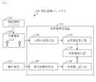
図1に基づいて、吸収量推定システム200の構成を説明する。
吸収量推定システム200は、測位補強システム210と、受信機網220と、観測衛星230と、吸収量推定装置100と、を備える。
測位補強システム210は、測位補強サービス用のシステムである。測位補強サービスの具体例は、センチメータ級測位補強サービス(CLAS)である。
受信機網220は、衛星測位システム用および測位補強システム210用の複数の受信機221である。衛星測位システムは、Global Navigation Satellite System(GNSS)と呼ばれる。衛星測位システムの具体例は、Global Positioning System(GPS)である。
観測衛星230は、観測用の人工衛星である。観測衛星230の具体例はSAR衛星である。SAR衛星は、合成開口レーダ(SAR)が搭載された人工衛星である。
吸収量推定装置100は、各森林地域における二酸化炭素の吸収量を推定する。*** Configuration description ***
The configuration of the absorbed amount estimation system 200 will be described based on FIG.
Absorption estimation system 200 includes
The
The
The
図2に基づいて、吸収量推定装置100の構成を説明する。
吸収量推定装置100は、プロセッサ101とメモリ102と補助記憶装置103と通信装置104と入出力インタフェース105といったハードウェアを備えるコンピュータである。これらのハードウェアは、信号線を介して互いに接続されている。The configuration of the absorbed amount estimating
The absorbed
プロセッサ101は、演算処理を行うICであり、他のハードウェアを制御する。例えば、プロセッサ101は、CPUである。
ICは、Integrated Circuitの略称である。
CPUは、Central Processing Unitの略称である。The
IC is an abbreviation for Integrated Circuit.
CPU is an abbreviation for Central Processing Unit.
メモリ102は揮発性または不揮発性の記憶装置である。メモリ102は、主記憶装置またはメインメモリとも呼ばれる。例えば、メモリ102はRAMである。メモリ102に記憶されたデータは必要に応じて補助記憶装置103に保存される。
RAMは、Random Access Memoryの略称である。
RAM is an abbreviation for Random Access Memory.
補助記憶装置103は不揮発性の記憶装置である。例えば、補助記憶装置103は、ROM、HDD、フラッシュメモリまたはこれらの組み合わせである。補助記憶装置103に記憶されたデータは必要に応じてメモリ102にロードされる。
ROMは、Read Only Memoryの略称である。
HDDは、Hard Disk Driveの略称である。
ROM is an abbreviation for Read Only Memory.
HDD is an abbreviation for Hard Disk Drive.
通信装置104はレシーバ及びトランスミッタである。例えば、通信装置104は通信チップまたはNICである。吸収量推定装置100の通信は通信装置104を用いて行われる。
NICは、Network Interface Cardの略称である。
NIC is an abbreviation for Network Interface Card.
入出力インタフェース105は、入力装置および出力装置が接続されるポートである。例えば、入出力インタフェース105はUSB端子であり、入力装置はキーボードおよびマウスであり、出力装置はディスプレイである。吸収量推定装置100の入出力は入出力インタフェース105を用いて行われる。
USBは、Universal Serial Busの略称である。The input/
USB is an abbreviation for Universal Serial Bus.
吸収量推定装置100は、可降水量算出部110と蒸発散位算出部120と森林特徴特定部130と蒸発散比算出部140と吸収量算出部150といった要素を備える。これらの要素はソフトウェアで実現される。 The
補助記憶装置103には、可降水量算出部110と蒸発散位算出部120と森林特徴特定部130と蒸発散比算出部140と吸収量算出部150としてコンピュータを機能させるための吸収量推定プログラムが記憶されている。吸収量推定プログラムは、メモリ102にロードされて、プロセッサ101によって実行される。
補助記憶装置103には、さらに、OSが記憶されている。OSの少なくとも一部は、メモリ102にロードされて、プロセッサ101によって実行される。
プロセッサ101は、OSを実行しながら、吸収量推定プログラムを実行する。
OSは、Operating Systemの略称である。The
The
The
OS is an abbreviation for Operating System.
吸収量推定プログラムの入出力データは記憶部190に記憶される。
メモリ102は記憶部190として機能する。但し、補助記憶装置103、プロセッサ101内のレジスタおよびプロセッサ101内のキャッシュメモリなどの記憶装置が、メモリ102の代わりに、又は、メモリ102と共に、記憶部190として機能してもよい。The input/output data of the absorbed amount estimation program are stored in the
吸収量推定装置100は、プロセッサ101を代替する複数のプロセッサを備えてもよい。 Absorption
吸収量推定プログラムは、光ディスクまたはフラッシュメモリ等の不揮発性の記録媒体にコンピュータ読み取り可能に記録(格納)することができる。 The absorption estimation program can be computer-readable and recorded (stored) in a non-volatile recording medium such as an optical disc or flash memory.
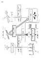
図3に基づいて、測位補強システム210の構成を説明する。
測位補強システム210は、複数の測位衛星211と、複数の電子基準点212と、情報生成設備213と、準天頂衛星214と、を備える。
各測位衛星211は、レンジング信号を発信する。レンジング信号を受信して得られる情報を「測位情報」と称する。
(1)レンジング信号は電離層と対流圏を通過するため、電離層遅延および対流圏遅延によって測位情報の誤差が発生する。
受信機から各衛星への方向を「スラント方向」と呼ぶ。
スラント方向における電離層遅延および対流圏遅延を「スラント方向遅延量(Slant Wet Delay)」と呼ぶ。スラント方向遅延量の略称はSWDである。
スラント方向遅延量は「視線方向対流圏遅延量」ともいう。
(2)情報生成設備213は、複数の電子基準点212で得られる複数の測位情報に基づいて測位情報の誤差量を算出し、測位情報の誤差量に基づいて測位補強情報を生成する。測位補強情報は、測位信号の誤差を補正するための情報である。なお、電子基準点212は日本国内の約1300ヶ所に設置されており、測位補強情報は約250ヶ所の電子基準点212で得られる情報を用いて生成される。
(3)測位補強情報は、準天頂衛星214を経由して各地のユーザ端末215に配信される。なお、測位補強情報は、圧縮されL6信号を使って配信される。
(4)ユーザ端末215は、各測位衛星211からレンジング信号を受信して測位情報を得て、測位補強情報を使って測位情報を補正する。そして、ユーザ端末215は、補正した測位情報を使って測位を行う。The configuration of the
The
Each
(1) Since the ranging signal passes through the ionosphere and troposphere, errors in positioning information occur due to ionospheric delay and tropospheric delay.
The direction from the receiver to each satellite is called the "slant direction".
The ionospheric and tropospheric delays in the slant direction are called "Slant Wet Delays". The abbreviation for the slant direction delay amount is SWD.
The slant direction delay amount is also referred to as "line-of-sight direction tropospheric delay amount".
(2) The
(3) The positioning augmentation information is distributed to
(4) The
***動作の説明***
吸収量推定システム200の動作の手順は吸収量推定方法に相当する。また、吸収量推定装置100の動作の手順は吸収量推定プログラムによる処理の手順に相当する。***Description of operation***
The operation procedure of the absorption estimation system 200 corresponds to the absorption estimation method. Further, the procedure of operation of the
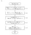
図4に基づいて、吸収量推定方法を説明する。
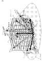
ステップS110において、可降水量算出部110は、遅延量データと気象観測データとに基づいて、観測領域の上方の三次元グリッド222に対して各グリッドマスの可降水量を算出する。観測領域の具体例は日本である。A method for estimating the amount of absorption will be described with reference to FIG.
In step S110, the precipitable water
三次元グリッド222は予め定義される。例えば、各グリッドマスは、250メートルを一辺とする立方体である。また、地表面からの三次元グリッド222の高さは11キロメートルである。 A three-dimensional grid 222 is predefined. For example, each grid mass is a cube with sides of 250 meters. Also, the height of the three-dimensional grid 222 from the ground surface is 11 kilometers.
三次元グリッド222の各マスを「グリッドマス」と称する。
三次元グリッド222の各交点を「グリッド点」と称する。Each square of the three-dimensional grid 222 is called a "grid square".
Each intersection point of the three-dimensional grid 222 is called a "grid point."
遅延量データは、各グリッド点のスラント方向遅延量を示すデータである。
気象観測データは、観測領域の各地域の気象観測量を示すデータである。気象観測量は、気象に関して観測された各種の値である。具体的な気象観測量は、気温および気圧などである。The delay amount data is data indicating the slant direction delay amount of each grid point.
The meteorological observation data is data indicating the meteorological observation amount of each area of the observation area. Meteorological observables are various observed values of weather. Specific meteorological observations include temperature and atmospheric pressure.
各グリッドマスの可降水量を示すデータを「可降水量データ」と称する。 Data indicating the amount of precipitable water for each grid square is referred to as "precipitable water amount data".
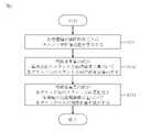
図5および図6に基づいて、ステップS110の手順を説明する。
図6において、矢印付き点線はスラント方向を表す。矢印付き点線上の各丸印は可降水量を表す。受信機221は、観測領域(日本)の各地点に配置されている。受信機221の符号は一つのみに付し、他の受信機221の符号は省略している。The procedure of step S110 will be described with reference to FIGS. 5 and 6. FIG.
In FIG. 6, a dotted line with an arrow represents the slant direction. Each circle on the dotted line with an arrow represents the amount of precipitable water. A
ステップS111において、各受信機221は、測位衛星211ごとに、スラント方向遅延量を算出する。 In step S<b>111 , each
具体的には、各受信機221は、各測位衛星211からレンジング信号を受信して測位情報を得て、準天頂衛星214から測位補強情報を受信する。そして、各受信機221は、測位衛星211ごとに、測位補強情報と測位情報とに基づいて測位演算を行い、測位補強情報と測位残差とに基づいてスラント方向遅延量を算出する。 Specifically, each
ステップS112において、可降水量算出部110は、各受信機221によって測位衛星211ごとに算出されたスラント方向遅延量を取得する。
例えば、可降水量算出部110は、各受信機221から測位衛星211ごとのスラント方向遅延量を受信する。In step S<b>112 , the precipitable water
For example, the precipitable water
次に、可降水量算出部110は、取得した複数のスラント方向遅延量を用いたトモグラフィ解析処理により、可降水量分布を3次元に表現する。
具体的には、可降水量算出部110は、文献(A)などの手法に組み込んだトモグラフィ解析処理を実行する。
文献(A):Ding et al. (2018, AMT) “A new approach for GNSS tomography from a few GNSS stations”Next, the precipitable water
Specifically, the precipitable water
Reference (A): Ding et al. (2018, AMT) "A new approach for GNSS tomography from a few GNSS stations"
ステップS113において、可降水量算出部110は気象観測データを取得する。
例えば、可降水量算出部110は、気象観測データを管理するサーバから気象観測データを受信する。In step S113, the precipitable water
For example, the precipitable water
そして、可降水量算出部110は、各グリッド点のスラント方向遅延量と各地域の気象観測量(地表気圧、温度)とに基づいて、各グリッドマスの可降水量を算出する。 Then, the precipitable water
図4に戻り、ステップS120から説明を続ける。
ステップS120において、蒸発散位算出部120は、各グリッドマスの可降水量に基づいて、観測領域の表面の二次元メッシュに対して、矩形領域である各メッシュマスの鉛直上方の蒸発散位を算出する。蒸発散位は、土壌からの蒸発量と植生からの蒸散量の合計である。
二次元メッシュは、三次元グリッド222の底面に相当する。
二次元メッシュの各マスを「メッシュマス」と称する。
二次元メッシュの各交点を「メッシュ点」と称する。Returning to FIG. 4, the description continues from step S120.
In step S120, the
A two-dimensional mesh corresponds to the bottom surface of the three-dimensional grid 222 .
Each square of the two-dimensional mesh is called a "mesh square".
Each intersection of the two-dimensional mesh is called a "mesh point".
各メッシュマスの蒸発散位は方法(1)または方法(2)によって算出される。 The evapotranspiration potential of each mesh mass is calculated by method (1) or method (2).
各メッシュマスの蒸発散位ETを算出するための方法(1)を説明する。
方法(1)は、文献(1)に開示された方法である。
文献(1):森 牧人、外2名、「GPS可降水量と地上気温の関係を利用した日蒸発散位の推定」、2007年、農業農村工学会論文 九州大学大学院 農学研究院A method (1) for calculating the evapotranspiration potential ET of each mesh mass will be described.
Method (1) is the method disclosed in Document (1).
Literature (1): Makito Mori, 2 others, "Estimation of daily evapotranspiration using the relationship between GPS precipitable water and surface temperature", 2007, Journal of the Society of Agriculture and Rural Engineering, Faculty of Agriculture, Kyushu University
各メッシュマスの蒸発散位ETは以下のように算出される。
まず、可降水量算出部110は、鉛直方向に並んだグリッドマスの可降水量PWVを合計して可降水量PWVSを算出する。
可降水量PWVSは、天頂方向の平均の可降水量であり、メッシュマスの蒸発散位ETに相当する。
次に、可降水量算出部110は、可降水量PWVSに係数を掛けて地上水蒸気圧eSを算出する。係数は、気象観測値を用いて対比分析と回帰分析とを行うことによってチューニングされる。月平均の可降水量PWVSに対する式の具体例を以下に示す。The evapotranspiration potential ET of each mesh mass is calculated as follows.
First, the precipitable water
The amount of precipitable water PWVS is the average amount of precipitable water in the zenith direction, and corresponds to the evapotranspiration potential ET of the mesh mass.
Next, the precipitable

そして、可降水量算出部110は、地上水蒸気圧eSを「ea」として代入したペルマン式を計算することによって、蒸発散位ETを算出する。ぺルマン式は以下のように表される。Then, the precipitable water

f(u2)は、風速関数であり、次のように表される。
f(u2)=0.26(1+0.537u2)f(u2 ) is the wind speed function and is expressed as follows.
f(u2 )=0.26(1+0.537u2 )
「Rn」、正味放射量である。
「G」は、地中熱流量である。
「Ta」は、地上気温である。
esat(Ta)は、Taに対する飽和水蒸気圧である。
「ea」は、地上水蒸気圧である。
「u2」は、高度2メートルの風速である。
「Δ」は、飽和水蒸気圧曲線の勾配である。
「γ」は、乾湿計定数である。
「l」は、蒸発の潜熱である。“Rn ”, net radiometric dose.
"G" is the geothermal heat flux.
"Ta " is the surface air temperature.
esat (Ta ) is the saturated water vapor pressure with respect to Ta .
"ea " is the surface water vapor pressure.
“u2 ” is the wind speed at 2 meters altitude.
"Δ" is the slope of the saturated water vapor pressure curve.
"γ" is the psychrometric constant.
"l" is the latent heat of vaporization.
上記の気象データは、当該グリッドマスの近傍の気象台で観測される気象要素を用いて算出される。具体的な気象要素は気圧、風速、気温、地上水蒸気圧および日照時間であり、各気象要素は日平均の値で示される。
GPS可降水量は、GNSS大気遅延量、気象台の気圧および気象台の気温を基に算出される。The above meteorological data is calculated using meteorological elements observed by meteorological observatories in the vicinity of the grid squares. Specific meteorological elements are atmospheric pressure, wind speed, temperature, water vapor pressure on the ground, and hours of sunshine, and each meteorological element is indicated by a daily average value.
The GPS precipitable water content is calculated based on the GNSS atmospheric delay, atmospheric pressure at the weather station, and air temperature at the weather station.
正味放射量Rnは、日常的に測定されることは稀であるので、以下の式を計算することによって算出される。The net radiation dose Rn is rarely routinely measured, so it is calculated by calculating the following formula.

「S0」は、大気外水平面日射量である。
「n」は、日照時間である。
「N」は、可照時間である。
「α」は、アルベドである。
「σ」は、ステファン・ボルツマン定数である。
「a」「b」は、日照計の定数である。“S0 ” is the extra-atmospheric horizontal solar radiation.
"n" is the sunshine hours.
"N" is the illumination time.
"α" is the albedo.
"σ" is the Stefan-Boltzmann constant.
"a" and "b" are constants of the sunshine meter.
各メッシュマスの蒸発散位に相当する蒸発散量Eを算出するための方法(2)を説明する。
方法(2)は、文献(2)に開示された方法である。文献(2)には、1か月未満という短い間隔での蒸発散位の推定方法を開示している。
文献(2):萬 和明、「大気水収支法にGPS可降水量を適用した蒸発散量推定手法の確立」、2012年、科研費研究 京都大学研究院
図7に、大気水収支法の概念を示す。Method (2) for calculating the evapotranspiration amount E corresponding to the evapotranspiration potential of each mesh mass will be described.
Method (2) is the method disclosed in Document (2). Reference (2) discloses a method for estimating potential evapotranspiration at short intervals of less than one month.
Literature (2): Kazuaki Yorozu, "Establishment of Evapotranspiration Estimation Method by Applying GPS Precipitable Water to Air Water Balance Method", 2012, Grants-in-Aid for Scientific Research Kyoto University Research Institute Fig. 7 shows the air water balance method Illustrate the concept.
各メッシュマスの蒸発散量Eは以下のように算出される。
まず、可降水量算出部110は、高さ方向に並んだグリッドマスのスラント方向遅延量を合計して水分量Wを算出する。水分量Wは、大気柱の水分量を意味する。
また、可降水量算出部110は、高さ方向に並んだグリッドマスのスラント方向遅延量をパラメータとして移流モデルを演算することによって、移流量∇HQを算出する。移流量∇HQは、大気柱の側面全体からの移流量を意味する。
移流モデルは、移流ベクトルと乱れの項で表現される。移流ベクトルは、移流成分を位置情報の一次式で近似する。移流ベクトルを求めるために適切な空間間隔(格子・メッシュの大きさ)が必要である。三次元グリッド222が移流モデルの代替となる。
また、可降水量算出部110は、降水量Pを取得する。降水量Pは、スラント方向遅延量に対応する時刻に観測された降水量である。例えば、降水量Pは気象観測データに含まれる。
そして、可降水量算出部110は、降水量Pと水分量Wと移流量∇HQを合計して蒸発散量Eを算出する。The evapotranspiration E of each mesh mass is calculated as follows.
First, the precipitable water
In addition, the precipitable water
The advection model is expressed in terms of advection vector and turbulence. The advection vector approximates the advection component with a linear expression of the position information. Appropriate spatial spacing (grid/mesh size) is required to obtain the advection vector. A three-dimensional grid 222 is an alternative to the advection model.
In addition, the precipitation
Then, the precipitable water
メッシュマス毎の蒸発散量Eは以下の式で表すことができる。
E = P + W +∇HQThe evapotranspiration amount E for each mesh mass can be expressed by the following formula.
E = P + W + ∇H Q
図4に戻り、ステップS130から説明を続ける。
ステップS130において、森林特徴特定部130は、衛星画像231に基づいて、観測領域の森林区域ごとに森林の特徴を特定する。
衛星画像231は、観測領域が映った画像であり、観測衛星230によって得られる。
森林区域は、森林が存在する区域である。区域はメッシュマスに相当する。
具体的な森林の特徴は、樹木の高さ、樹木の種類および森林の境界などである。森林の特徴は「土地分類」ともいう。Returning to FIG. 4, the description continues from step S130.
In step S<b>130 , the forest
A satellite image 231 is an image showing the observation area and is obtained by the
A forest area is an area where forest exists. A region corresponds to a mesh mass.
Specific forest characteristics include tree height, tree species and forest boundaries. Forest characteristics are also called 'land classification'.
ステップS130の手順を以下に説明する。
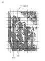
図8に、2次元メッシュで区切られた衛星画像231を示す。濃い網掛けは森林を表し、薄い網掛けは非森林を表す。非森林には伐採地が含まれる。
まず、森林特徴特定部130は、衛星画像231を取得する。例えば、森林特徴特定部130は、観測衛星230から衛星画像231を受信する。または、森林特徴特定部130は、観測衛星230から観測データを受信し、観測データを用いて衛星画像231を生成する。
次に、森林特徴特定部130は、衛星画像231を2次元メッシュで区切る。The procedure of step S130 will be described below.
FIG. 8 shows a satellite image 231 partitioned by a two-dimensional mesh. Dark shading represents forest and light shading represents non-forest. Non-forest includes deforested land.
First, the forest
Next, the forest
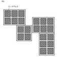
図9に、複数の森林区域232を示す。各網掛けのマスが森林区域である。
次に、森林特徴特定部130は、衛星画像231を解析することによって、各森林区域に相当するメッシュマスを特定する。FIG. 9 shows multiple forest areas 232 . Each shaded square is a forest area.
Next, the forest
図10に、モーションステレオの概念を示す。
そして、森林特徴特定部130は、衛星画像231を解析することによって、各森林区域の森林の特徴を特定する。
例えば、森林特徴特定部130は、樹木の高さを次のように特定する。まず、森林特徴特定部130は、衛星画像231のベースライン情報を使って樹冠の高さを計測する。また、森林特徴特定部130は、樹木を除いた地表面の高さを、整備済の数値標高モデル(DEM:Digital Elevation Model)から取得する。DEMは、記憶部190に記憶されてもよいし、外部サーバで管理されてもよい。そして、森林特徴特定部130は、樹冠の高さから地表面の高さを引いて樹木の高さを算出する。樹冠の高さを計測することで、樹木の最新の成長分の反映が可能である。
森林の特徴は、人工知能(AI)またはディープラーニング技術を使って特定されてもよい。FIG. 10 shows the concept of motion stereo.
Then, the forest
For example, the forest
Forest features may be identified using artificial intelligence (AI) or deep learning techniques.
図4に戻り、ステップS140から説明を続ける。
ステップS140において、蒸発散比算出部140は、森林区域ごとに、森林の特徴に基づいて、蒸発散比を算出する。
蒸発散比は、土壌からの蒸発量と樹木からの蒸散量の比である。
なお、日本国土の85パーセントは森林である。そして、例えば直径30~60キロメートルの範囲で、森林のみの地域はたくさん存在する。この範囲は、1つの受信機による可降水量の測定範囲に相当する。
そのため、蒸散量は蒸発散位と近似することができ、蒸発散比算出部140の出力は1と近似してもよい。
以下、間伐の行われた人工林、村落および道路を含めて説明を行う。Returning to FIG. 4, the description continues from step S140.
In step S140, the
Evapotranspiration ratio is the ratio of transpiration from soil to transpiration from trees.
85% of the land of Japan is forest. And there are many forest-only areas, for example, ranging from 30 to 60 kilometers in diameter. This range corresponds to the measurement range of precipitable water content by one receiver.
Therefore, the amount of transpiration can be approximated to the evapotranspiration potential, and the output of the
Below, we will explain the thinned planted forests, villages and roads.
例えば、蒸発散比算出部140は、森林特徴特定部130によって得られた森林の特徴(樹木の高さ、樹木の種類および森林の境界)に基づいて、メッシュマス毎に森林区域と非森林区域の面積比を算出する。算出される面積比が蒸発散比となる。
非森林区域には、伐採地、村落および道路などが含まれる。For example, the evapotranspiration
Non-forest areas include logging lands, villages and roads.
ステップS150において、吸収量算出部150は、森林区域ごとに、対応するメッシュマスの蒸発散位と、蒸発散比と、に基づいて、二酸化炭素(CO2)の吸収量を算出する。 In step S150, the
各森林区域のCO2吸収量は、各種情報と以下のような関係を有する。
蒸散量 ∝ 光合成量 ∝ CO2吸収量The amount of CO2 absorbed by each forest area has the following relationships with various types of information.
Transpiration ∝ Photosynthesis ∝ CO2 absorption
したがって、各森林区域のCO2吸収量は、以下のように算出される。
まず、吸収量算出部150は、ステップS120で算出された蒸発散位から、森林区域に対応するメッシュマスの蒸発散位を選択する。
また、吸収量算出部150は、ステップS140で算出された蒸発散比から、森林区域の蒸発散比を選択する。
次に、吸収量算出部150は、選択した蒸発散位に選択した蒸発散比を掛けて蒸散量を算出する。
そして、吸収量算出部150は、算出した蒸散量に比例パラメータ(係数)を掛けてCO2吸収量を算出する。Therefore, the CO2 absorption of each forest area is calculated as follows.
First, the
Also, the
Next, the
Then, the
比例パラメータ(係数)は、次のようにチューニングされる。
光合成の原理などにより、蒸散量とCO2吸収量が比例することが一般的に知られている。
比例パラメータ(係数)は、樹木の種類(広葉樹または針葉樹など)、樹木の高さおよび葉量などに基づいて、テーブルから取得される。そのテーブルは、一般的に知られる算出方法に基づいてチューニングされる。The proportional parameter (coefficient) is tuned as follows.
It is generally known that the amount of transpiration is proportional to the amount of CO2 absorption due to the principle of photosynthesis.
Proportional parameters (coefficients) are obtained from the table based on tree type (such as broadleaf or conifer), tree height and leaf mass. The table is tuned based on commonly known calculation methods.
以下のウェブページ(a~c)には、CO2吸収量に関する情報が開示されている。
(a)https://kids.gakken.co.jp/kagaku/eco110/ecology0070/
(b)https://www.pref.wakayama.lg.jp/prefg/032000/gakusyu/program/tyugakko_d/fil/tyupro1-5.pdf
(c)http://www.nilim.go.jp/lab/ddg/naiyo/co2/co2.htmlThe following web pages (a-c) disclose information on CO2 absorption.
(a) https://kids. gakken. co. jp/kagaku/eco110/ecology0070/
(b) https://www. pref. wakayama. lg. jp/prefg/032000/gakusyu/program/tyugakko_d/fil/tyupro1-5. pdf
(c) http://www. nilim. go. jp/lab/ddg/naiyo/co2/co2. html
そして、吸収量算出部150は、各森林区域の二酸化炭素の吸収量を出力する。例えば、吸収量算出部150は、各森林区域の二酸化炭素の吸収量をディスプレイに表示する。
例えば、1か月の観測が行われた場合、森林が1か月間に吸収した二酸化炭素の量がディスプレイに表示される。Then, the
For example, if one month's observations are made, the display will show the amount of carbon dioxide that the forest has absorbed in one month.
***実施の形態1の効果***
実施の形態1により、森林の蒸散量に基づいてCO2吸収量を推定することができる。そのため、CO2吸収量の「見える化」および「定量化」が可能である。*** Effect of Embodiment 1 ***
According to Embodiment 1, the amount of CO2 absorption can be estimated based on the amount of transpiration in the forest. Therefore, "visualization" and "quantification" of CO2 absorption are possible.
実施の形態1は、全天候性および広域での均一性を有するデータを観測できる多種の人工衛星を活用して、CO2吸収量を高い精度で効率的に推定する。そして、実施の形態1は、地域および広さに寄らず同じ基準で算定が可能(スケーラブル)なため、将来、世界的に、森林のCO2吸収量のクレジット化(対価の算出)に寄与するものである。 Embodiment 1 utilizes various artificial satellites capable of observing data having uniformity in all weather conditions and over a wide area, and efficiently estimates the amount of CO2 absorption with a high degree of accuracy. In addition, since Embodiment 1 can be calculated based on the same standard regardless of region and size (scalable), it will contribute to crediting (calculation of consideration) of CO2 absorption by forests worldwide in the future. is.
***実施の形態1の補足***
吸収量推定システム200は、可降水量および蒸発散位を算出するための算出システムとして利用することができる。*** Supplement to Embodiment 1 ***
The absorption estimation system 200 can be used as a calculation system for calculating the amount of precipitable water and the evapotranspiration potential.
実施の形態1は、好ましい形態の例示であり、本開示の技術的範囲を制限することを意図するものではない。実施の形態1は、部分的に実施してもよいし、他の形態と組み合わせて実施してもよい。フローチャート等を用いて説明した手順は、適宜に変更してもよい。 Embodiment 1 is an example of preferred modes and is not intended to limit the technical scope of the present disclosure. Embodiment 1 may be partially implemented, or may be implemented in combination with other modes. The procedures described using flowcharts and the like may be changed as appropriate.
吸収量推定装置100は、2台以上の装置で実現されてもよい。
吸収量推定装置100の要素である「部」は、ソフトウェア、ハードウェア、ファームウェアまたはこれらの組み合わせのいずれで実現されてもよい。
吸収量推定装置100の要素である「部」は、「処理」、「工程」、「回路」または「サーキットリ」と読み替えてもよい。
The “unit”, which is an element of the
The "unit", which is an element of the
100 吸収量推定装置、101 プロセッサ、102 メモリ、103 補助記憶装置、104 通信装置、105 入出力インタフェース、110 可降水量算出部、120 蒸発散位算出部、130 森林特徴特定部、140 蒸発散比算出部、150 吸収量算出部、190 記憶部、200 吸収量推定システム、210 測位補強システム、211 測位衛星、212 電子基準点、213 情報生成設備、214 準天頂衛星、215 ユーザ端末、220 受信機網、221 受信機、222 三次元グリッド、230 観測衛星、231 衛星画像、232 森林区域。 100
Claims (9)
Translated fromJapanese各グリッドマスの可降水量に基づいて、前記観測領域の表面の二次元メッシュに対して、矩形領域である各メッシュマスの鉛直上方の蒸発散位を算出する蒸発散位算出部と、
前記観測領域が映った衛星画像に基づいて、前記観測領域の森林区域ごとに森林の特徴を特定する森林特徴特定部と、
森林区域ごとに、森林の特徴に基づいて、土壌からの蒸発量と樹木からの蒸散量の比である蒸発散比を算出する蒸発散比算出部と、
森林区域ごとに、対応するメッシュマスの蒸発散位と、前記蒸発散比と、に基づいて、二酸化炭素の吸収量を算出する吸収量算出部と、
を備える吸収量推定システム。Based on the delay amount data indicating the slant direction delay amount of each grid point with respect to the three-dimensional grid above the observation area and the meteorological observation data indicating the meteorological observation amount of each region of the observation area, the three-dimensional a precipitable water amount calculation unit that calculates the precipitable water amount of each grid mass with respect to the grid;
an evapotranspiration calculation unit that calculates the evapotranspiration potential vertically above each mesh square, which is a rectangular area, with respect to the two-dimensional mesh on the surface of the observation area, based on the amount of precipitable water of each grid square;
a forest feature identifying unit that identifies forest features for each forest area in the observation area based on a satellite image of the observation area;
an evapotranspiration ratio calculation unit that calculates an evapotranspiration ratio, which is the ratio of the amount of evaporation from the soil to the amount of transpiration from the trees, for each forest area, based on the characteristics of the forest;
an absorption amount calculation unit that calculates the absorption amount of carbon dioxide based on the evapotranspiration potential of the corresponding mesh mass and the evapotranspiration ratio for each forest area;
Absorption estimation system with
レンジング信号を発信する複数の測位衛星と、
前記観測領域の異なる地点に配置される複数の受信機と、を備え、
前記複数の受信機のそれぞれは、測位衛星ごとに、スラント方向遅延量を算出し、
前記可降水量算出部は、各スラント方向遅延量を各グリッド点に投影して各グリッド点のスラント方向遅延量を算出し、前記遅延量データを生成する
請求項1に記載の吸収量推定システム。The absorption estimation system further comprises:
a plurality of positioning satellites that emit ranging signals;
a plurality of receivers arranged at different points in the observation area;
Each of the plurality of receivers calculates a slant direction delay amount for each positioning satellite,
The absorption estimation system according to claim 1, wherein the precipitable water amount calculation unit projects each slant direction delay amount onto each grid point, calculates the slant direction delay amount of each grid point, and generates the delay amount data. .
請求項1または請求項2に記載の吸収量推定システム。The forest feature identification unit divides the satellite image into two-dimensional meshes, identifies mesh masses corresponding to each forest area by analyzing the satellite image, and analyzes the satellite image to identify the forest in each forest area. 3. An absorption estimation system according to claim 1 or claim 2, which specifies the features of:
請求項1から請求項3のいずれか1項に記載の吸収量推定システム。The absorption calculation unit calculates the amount of transpiration by multiplying the evapotranspiration potential by the evapotranspiration ratio, and calculates the amount of absorption by multiplying the calculated amount of transpiration by a proportional parameter. Absorption amount estimation system according to any one of claims 1 to 3.
各グリッドマスの可降水量に基づいて、前記観測領域の表面の二次元メッシュに対して、矩形領域である各メッシュマスの鉛直上方の蒸発散位を算出し、
前記観測領域が映った衛星画像に基づいて、前記観測領域の森林区域ごとに森林の特徴を特定し、
森林区域ごとに、森林の特徴に基づいて、土壌からの蒸発量と樹木からの蒸散量の比である蒸発散比を算出し、
森林区域ごとに、対応するメッシュマスの蒸発散位と、前記蒸発散比と、に基づいて、二酸化炭素の吸収量を算出する
吸収量推定方法。Based on the delay amount data indicating the slant direction delay amount of each grid point with respect to the three-dimensional grid above the observation area and the meteorological observation data indicating the meteorological observation amount of each region of the observation area, the three-dimensional Calculate the precipitable water content of each grid mass for the grid,
Based on the precipitable water content of each grid mass, calculating the evapotranspiration position vertically above each mesh mass, which is a rectangular region, with respect to the two-dimensional mesh on the surface of the observation region,
Based on the satellite image of the observation area, identifying the characteristics of the forest for each forest area in the observation area,
For each forest area, calculate the evapotranspiration ratio, which is the ratio of the amount of evaporation from the soil to the amount of transpiration from the trees, based on the characteristics of the forest,
A method for estimating the amount of absorption of carbon dioxide for each forest area, based on the evapotranspiration potential of the corresponding mesh mass and the evapotranspiration ratio.
各グリッドマスの可降水量に基づいて、前記観測領域の表面の二次元メッシュに対して、矩形領域である各メッシュマスの鉛直上方の蒸発散位を算出する蒸発散位算出部と、
前記観測領域が映った衛星画像に基づいて、前記観測領域の森林区域ごとに森林の特徴を特定する森林特徴特定部と、
森林区域ごとに、森林の特徴に基づいて、土壌からの蒸発量と樹木からの蒸散量の比である蒸発散比を算出する蒸発散比算出部と、
森林区域ごとに、対応するメッシュマスの蒸発散位と、前記蒸発散比と、に基づいて、二酸化炭素の吸収量を算出する吸収量算出部として、
コンピュータを機能させるための吸収量推定プログラム。Based on the delay amount data indicating the slant direction delay amount of each grid point with respect to the three-dimensional grid above the observation area and the meteorological observation data indicating the meteorological observation amount of each region of the observation area, the three-dimensional a precipitable water amount calculation unit that calculates the precipitable water amount of each grid mass with respect to the grid;
an evapotranspiration calculation unit that calculates the evapotranspiration potential vertically above each mesh square, which is a rectangular area, with respect to the two-dimensional mesh on the surface of the observation area, based on the amount of precipitable water of each grid square;
a forest feature identifying unit that identifies forest features for each forest area in the observation area based on a satellite image of the observation area;
an evapotranspiration ratio calculation unit that calculates an evapotranspiration ratio, which is the ratio of the amount of evaporation from the soil to the amount of transpiration from the trees, for each forest area, based on the characteristics of the forest;
For each forest area, an absorption amount calculation unit that calculates the absorption amount of carbon dioxide based on the evapotranspiration potential of the corresponding mesh mass and the evapotranspiration ratio,
Absorption estimation program to make the computer work.
を備える算出システム。Based on the delay amount data indicating the slant direction delay amount of each grid point with respect to the three-dimensional grid above the observation area and the meteorological observation data indicating the meteorological observation amount of each region of the observation area, the three-dimensional A calculation system comprising a precipitable water quantity calculator for calculating the precipitable water quantity of each grid mass for a grid.
各グリッドマスの可降水量に基づいて、前記観測領域の表面の二次元メッシュに対して、矩形領域である各メッシュマスの鉛直上方の蒸発散位を算出する蒸発散位算出部と、
を備える算出システム。Based on the delay amount data indicating the slant direction delay amount of each grid point with respect to the three-dimensional grid above the observation area and the meteorological observation data indicating the meteorological observation amount of each region of the observation area, the three-dimensional a precipitable water amount calculation unit that calculates the precipitable water amount of each grid mass with respect to the grid;
an evapotranspiration calculation unit that calculates the evapotranspiration potential vertically above each mesh square, which is a rectangular area, with respect to the two-dimensional mesh on the surface of the observation area, based on the amount of precipitable water of each grid square;
A calculation system comprising:
レンジング信号を発信する複数の測位衛星と、
前記観測領域の異なる地点に配置される複数の受信機と、を備え、
前記複数の受信機のそれぞれは、測位衛星ごとに、スラント方向遅延量を算出し、
前記可降水量算出部は、各スラント方向遅延量を各グリッド点に投影して各グリッド点のスラント方向遅延量を算出し、前記遅延量データを生成する
請求項7または請求項8に記載の算出システム。The calculation system further comprises:
a plurality of positioning satellites that emit ranging signals;
a plurality of receivers arranged at different points in the observation area;
Each of the plurality of receivers calculates a slant direction delay amount for each positioning satellite,
9. The precipitable water amount calculation unit according to claim 7 or 8, wherein each slant direction delay amount is projected onto each grid point to calculate the slant direction delay amount of each grid point, thereby generating the delay amount data. calculation system.
Priority Applications (1)
| Application Number | Priority Date | Filing Date | Title |
|---|---|---|---|
| JP2021102154AJP7668685B2 (en) | 2021-06-21 | 2021-06-21 | Absorption amount estimation system, absorption amount estimation method, absorption amount estimation program, and calculation system |
Applications Claiming Priority (1)
| Application Number | Priority Date | Filing Date | Title |
|---|---|---|---|
| JP2021102154AJP7668685B2 (en) | 2021-06-21 | 2021-06-21 | Absorption amount estimation system, absorption amount estimation method, absorption amount estimation program, and calculation system |
Publications (2)
| Publication Number | Publication Date |
|---|---|
| JP2023001437Atrue JP2023001437A (en) | 2023-01-06 |
| JP7668685B2 JP7668685B2 (en) | 2025-04-25 |
Family
ID=84688760
Family Applications (1)
| Application Number | Title | Priority Date | Filing Date |
|---|---|---|---|
| JP2021102154AActiveJP7668685B2 (en) | 2021-06-21 | 2021-06-21 | Absorption amount estimation system, absorption amount estimation method, absorption amount estimation program, and calculation system |
Country Status (1)
| Country | Link |
|---|---|
| JP (1) | JP7668685B2 (en) |
Cited By (3)
| Publication number | Priority date | Publication date | Assignee | Title |
|---|---|---|---|---|
| CN116340710A (en)* | 2023-05-30 | 2023-06-27 | 中国科学院精密测量科学与技术创新研究院 | Neutral atmospheric skew delay calculation method based on layered rapid three-dimensional ray tracing |
| CN116992351A (en)* | 2023-09-26 | 2023-11-03 | 云南省林业调查规划院 | Forest carbon sink potential prediction method and device |
| JP2024146587A (en)* | 2023-03-31 | 2024-10-15 | アスエネ株式会社 | Forest management methods |
Citations (2)
| Publication number | Priority date | Publication date | Assignee | Title |
|---|---|---|---|---|
| JP2007085755A (en)* | 2005-09-20 | 2007-04-05 | Kddi Corp | Meteorological data distribution device, local meteorological data distribution system, and meteorological data estimation method in the same system |
| US20130179078A1 (en)* | 2009-11-26 | 2013-07-11 | Tanguy Griffon | Method for measuring weekly and annual emissions of a greenhouse gas over a given surface area |
- 2021
- 2021-06-21JPJP2021102154Apatent/JP7668685B2/enactiveActive
Patent Citations (2)
| Publication number | Priority date | Publication date | Assignee | Title |
|---|---|---|---|---|
| JP2007085755A (en)* | 2005-09-20 | 2007-04-05 | Kddi Corp | Meteorological data distribution device, local meteorological data distribution system, and meteorological data estimation method in the same system |
| US20130179078A1 (en)* | 2009-11-26 | 2013-07-11 | Tanguy Griffon | Method for measuring weekly and annual emissions of a greenhouse gas over a given surface area |
Non-Patent Citations (3)
| Title |
|---|
| 光田 靖 他: "森林炭素動態シミュレーションシステムを用いた気候変動が森林炭素吸収量に及ぼす影響評価の試行", 統計数理, vol. 第61巻 第2号, JPN7025001080, 2013, pages 181 - 188, ISSN: 0005551836* |
| 小司 禎教 他: "GPS 気象学:GPS 水蒸気情報システムの構築と気象学・測地学・水文学への応用に関する研究", 測地学会誌, vol. 第55巻第1号, JPN6024043958, 23 March 2009 (2009-03-23), ISSN: 0005451905* |
| 森 牧人 他: "GPS可降水量を用いた月蒸発散位の推定", 農業農村工学会論文集, vol. 第250巻, JPN6024043959, August 2007 (2007-08-01), pages 7 - 15, ISSN: 0005451906* |
Cited By (5)
| Publication number | Priority date | Publication date | Assignee | Title |
|---|---|---|---|---|
| JP2024146587A (en)* | 2023-03-31 | 2024-10-15 | アスエネ株式会社 | Forest management methods |
| CN116340710A (en)* | 2023-05-30 | 2023-06-27 | 中国科学院精密测量科学与技术创新研究院 | Neutral atmospheric skew delay calculation method based on layered rapid three-dimensional ray tracing |
| CN116340710B (en)* | 2023-05-30 | 2023-09-12 | 中国科学院精密测量科学与技术创新研究院 | Neutral atmospheric skew delay calculation method based on layered rapid three-dimensional ray tracing |
| CN116992351A (en)* | 2023-09-26 | 2023-11-03 | 云南省林业调查规划院 | Forest carbon sink potential prediction method and device |
| CN116992351B (en)* | 2023-09-26 | 2023-11-28 | 云南省林业调查规划院 | Forest carbon sink potential prediction method and device |
Also Published As
| Publication number | Publication date |
|---|---|
| JP7668685B2 (en) | 2025-04-25 |
Similar Documents
| Publication | Publication Date | Title |
|---|---|---|
| Giannetti et al. | A new approach with DTM-independent metrics for forest growing stock prediction using UAV photogrammetric data | |
| Eker et al. | A comparative analysis of UAV-RTK and UAV-PPK methods in mapping different surface types | |
| JP2023001437A (en) | Absorption Estimation System, Absorption Estimation Method, Absorption Estimation Program and Calculation System | |
| Hoffmeister et al. | Crop height variability detection in a single field by multi-temporal terrestrial laser scanning | |
| KR102008017B1 (en) | Calculation method of amount of solar radiation of construction site of a solar photovoltaic power station by using drone | |
| Chopping et al. | Forest aboveground biomass in the southwestern United States from a MISR multi-angle index, 2000–2015 | |
| Petropoulos et al. | Exploring the use of Unmanned Aerial Vehicles (UAVs) with the simplified ‘triangle’technique for soil water content and evaporative fraction retrievals in a Mediterranean setting | |
| Yue et al. | Evaluating the effect of the global ionospheric map on aiding retrieval of radio occultation electron density profiles | |
| Moravec et al. | Digital elevation models as predictors of yield: comparison of an UAV and other elevation data sources. | |
| Calou et al. | Estimation of maize biomass using unmanned aerial vehicles | |
| Palluconi et al. | An atmospheric correction method for ASTER thermal radiometry over land | |
| Persson et al. | National forest biomass mapping using the two-level model | |
| Green | Relationships between polarimetric SAR backscatter and forest canopy and sub-canopy biophysical properties | |
| Kandel | Estimation of above ground forest biomass and carbon stock by integrating LiDAR, satellite image and field measurement in Nepal | |
| Stephenson et al. | High resolution habitat suitability modelling for an endemic restricted-range Hawaiian insect (Nysius wekiuicola, Hemiptera: Lygaeidae) | |
| Urban et al. | A novel approach to estimate systematic and random error of terrain derived from UAVs: a case study from a post-mining site | |
| Gautam et al. | Estimation of forest carbon using Lidar-Assisted Multi-source Programme (LAMP) in Nepal | |
| Rusli et al. | Accuracy assessment of DEM from UAV and TanDEM-X imagery | |
| Altmann et al. | Long-term monitoring (1953–2019) of geomorphologically active sections on LIA lateral moraines under changing meteorological conditions | |
| De Haan et al. | Use of GNSS Tropospheric Products for High-Resolution, Rapid-Update NWP and Severe Weather Forecasting (Working Group 2) | |
| Sahu et al. | Classification of orchard crop using sentinel-1A synthetic aperture radar data | |
| Oliveira et al. | Methodology for the spatialisation of a reference evapotranspiration from SRTM data | |
| Baldauf et al. | Fundamentals and applications of remote sensing in tropical forestry | |
| Klimánek | Analysis of the accuracy of GPS Trimble JUNO ST measurement in the conditions of forest canopy | |
| Idi | Spatio-temporal mapping of solar energy potential of Dutse, Jigawa State Nigeria using arcgis solar radiation spatial analyst tool |
Legal Events
| Date | Code | Title | Description |
|---|---|---|---|
| A621 | Written request for application examination | Free format text:JAPANESE INTERMEDIATE CODE: A621 Effective date:20240321 | |
| A977 | Report on retrieval | Free format text:JAPANESE INTERMEDIATE CODE: A971007 Effective date:20241023 | |
| A131 | Notification of reasons for refusal | Free format text:JAPANESE INTERMEDIATE CODE: A131 Effective date:20241105 | |
| A521 | Request for written amendment filed | Free format text:JAPANESE INTERMEDIATE CODE: A523 Effective date:20241218 | |
| TRDD | Decision of grant or rejection written | ||
| A01 | Written decision to grant a patent or to grant a registration (utility model) | Free format text:JAPANESE INTERMEDIATE CODE: A01 Effective date:20250318 | |
| A61 | First payment of annual fees (during grant procedure) | Free format text:JAPANESE INTERMEDIATE CODE: A61 Effective date:20250415 | |
| R150 | Certificate of patent or registration of utility model | Ref document number:7668685 Country of ref document:JP Free format text:JAPANESE INTERMEDIATE CODE: R150 |