JP2023000383A - Resist film forming method and resist film - Google Patents
Resist film forming method and resist filmDownload PDFInfo
- Publication number
- JP2023000383A JP2023000383AJP2021101156AJP2021101156AJP2023000383AJP 2023000383 AJP2023000383 AJP 2023000383AJP 2021101156 AJP2021101156 AJP 2021101156AJP 2021101156 AJP2021101156 AJP 2021101156AJP 2023000383 AJP2023000383 AJP 2023000383A
- Authority
- JP
- Japan
- Prior art keywords
- resist film
- resist
- film
- mpa
- forming
- Prior art date
- Legal status (The legal status is an assumption and is not a legal conclusion. Google has not performed a legal analysis and makes no representation as to the accuracy of the status listed.)
- Granted
Links
Images


Classifications
- H—ELECTRICITY
- H01—ELECTRIC ELEMENTS
- H01L—SEMICONDUCTOR DEVICES NOT COVERED BY CLASS H10
- H01L21/00—Processes or apparatus adapted for the manufacture or treatment of semiconductor or solid state devices or of parts thereof
- H01L21/02—Manufacture or treatment of semiconductor devices or of parts thereof
- H01L21/04—Manufacture or treatment of semiconductor devices or of parts thereof the devices having potential barriers, e.g. a PN junction, depletion layer or carrier concentration layer
- H01L21/50—Assembly of semiconductor devices using processes or apparatus not provided for in a single one of the groups H01L21/18 - H01L21/326 or H10D48/04 - H10D48/07 e.g. sealing of a cap to a base of a container
- H01L21/56—Encapsulations, e.g. encapsulation layers, coatings
Landscapes
- Engineering & Computer Science (AREA)
- Physics & Mathematics (AREA)
- Condensed Matter Physics & Semiconductors (AREA)
- General Physics & Mathematics (AREA)
- Manufacturing & Machinery (AREA)
- Computer Hardware Design (AREA)
- Microelectronics & Electronic Packaging (AREA)
- Power Engineering (AREA)
- Application Of Or Painting With Fluid Materials (AREA)
- Exposure Of Semiconductors, Excluding Electron Or Ion Beam Exposure (AREA)
Abstract
Translated fromJapaneseDescription
Translated fromJapanese本開示は、レジスト膜の形成方法及びレジスト膜に関する。 The present disclosure relates to a method of forming a resist film and the resist film.
従来、厚膜のレジスト膜を形成する方法が知られている。
例えば、特許文献1には、基板上に、レジストの溶液をスピンコート法により塗布し、塗布膜を形成すること、上記塗布膜を加熱することにより溶媒を除去し、レジスト膜を得ること、上記基板の周囲に、必要なレジスト膜厚と同じ厚さのスペーサを配置した後、上記レジスト膜を再度加熱すること、及び、加熱により柔らかくなったレジスト膜に対し、ガラス基板を用いてプレスを行うことを含む、厚膜のレジスト膜を形成する方法が開示されている。特許文献1には、上記方法により、膜の厚さが250μmである厚膜のネガレジストを形成したことが記載されている。Conventionally, a method for forming a thick resist film is known.
For example, in
近年、常温で高い粘度を有し、かつ、加熱により上記粘度が低下するレジストを用いて、レジスト膜を形成することが行われている。特許文献1においても、ガラス転移温度が40℃~50℃であり、僅かな加熱で柔らかくなるレジストの溶液を用いている。
上記のような特性を有するレジストの代表的なものとしては、日本化薬(株)製のSU-8〔商品のシリーズ名〕が知られている。SU-8によれば、厚膜のレジスト膜を形成できるとされている。しかし、SU-8を用いてレジスト膜を形成すると、プリベーク(所謂、溶媒を除去するための熱処理)の際の加熱によりレジストが流動することに起因して、最終的に得られるレジスト膜の厚さが想定していたよりも薄くなり、かつ、面内の膜厚変動が大きくなるという問題が生じ得る。In recent years, a resist film has been formed using a resist that has a high viscosity at room temperature and whose viscosity decreases when heated.
SU-8 (product series name) manufactured by Nippon Kayaku Co., Ltd. is known as a typical resist having the above properties. According to SU-8, it is said that a thick resist film can be formed. However, when a resist film is formed using SU-8, the thickness of the finally obtained resist film increases due to the flow of the resist due to heating during prebaking (so-called heat treatment for removing the solvent). A problem may occur in that the thickness becomes thinner than expected and the in-plane film thickness variation increases.
本開示の一実施形態が解決しようとする課題は、常温で高い粘度を有し、かつ、加熱により上記粘度が低下するレジストを用いたレジスト膜の形成方法であって、膜厚が300μm以上であり、かつ、面内の膜厚変動が10%以内であるレジスト膜を形成できるレジスト膜の形成方法を提供することにある。
本開示の他の実施形態が解決しようとする課題は、上記レジスト膜の形成方法により形成されたレジスト膜を提供することにある。A problem to be solved by an embodiment of the present disclosure is a method for forming a resist film using a resist that has a high viscosity at room temperature and whose viscosity is reduced by heating, wherein the film thickness is 300 μm or more. It is an object of the present invention to provide a resist film forming method capable of forming a resist film having an in-plane film thickness variation of 10% or less.
A problem to be solved by another embodiment of the present disclosure is to provide a resist film formed by the method for forming a resist film described above.
上記課題を解決するための具体的な手段には、以下の実施態様が含まれる。
[1] 基板上に、23℃における粘度が1000mPa・s~30000mPa・sであるレジストを付与し、上記レジストの膜を形成する工程Aと、
上記レジストの流出を規制する規制部材に囲まれた領域内に配置された上記レジストの膜に対し、熱処理を行う工程Bと、
上記レジストの膜を所望の厚さに調整する調整部材の設置により形成された領域内に配置された、上記熱処理後の上記レジストの膜に対し、シートを介して、熱プレスを行う工程Cと、
を含むレジスト膜の形成方法。
[2] 上記工程Cにおける上記シートの上記レジストの膜側の面の算術平均粗さRaは、10μm以下である[1]に記載のレジスト膜の形成方法。
[3] 上記工程Cにおける上記シートのヤング率は、40MPa~5500MPaである[1]又は[2]に記載のレジスト膜の形成方法。
[4] 上記工程Cにおける上記調整部材と、上記熱処理後の上記レジストの膜とは、面内方向に間隔をあけて配置されている[1]~[3]のいずれか1つに記載のレジスト膜の形成方法。
[5] 上記工程Bでは、上記レジストの膜の温度を段階的に又は連続的に上げることにより、上記レジストの粘度を5000mPa・s以下にする[1]~[4]のいずれか1つに記載のレジスト膜の形成方法。
[6] 上記工程Bでは、粘度が5000mPa・s以下である上記レジストの膜に対し、真空環境下で熱処理を行う[1]~[5]のいずれか1つに記載のレジスト膜の形成方法。
[7] 上記工程Cにおける上記熱プレスの温度は、上記工程Bにおける上記熱処理の温度よりも低い[1]~[6]のいずれか1つに記載のレジスト膜の形成方法。
[8] [1]~[7]のいずれか1つに記載のレジスト膜の形成方法により形成されたレジスト膜であって、膜厚が300μm以上であり、かつ、面内の膜厚変動が10%以内であるレジスト膜。Specific means for solving the above problems include the following embodiments.
[1] A step A of applying a resist having a viscosity of 1000 mPa·s to 30000 mPa·s at 23° C. to a substrate to form a film of the resist;
a step B of heat-treating the resist film arranged in a region surrounded by a regulating member for regulating outflow of the resist;
a step C of hot-pressing, via a sheet, the resist film after the heat treatment, which is arranged in a region formed by installing an adjusting member for adjusting the thickness of the resist film to a desired thickness; ,
A method of forming a resist film comprising
[2] The method of forming a resist film according to [1], wherein the surface of the sheet on the resist film side in the step C has an arithmetic mean roughness Ra of 10 μm or less.
[3] The method of forming a resist film according to [1] or [2], wherein the sheet in the step C has a Young's modulus of 40 MPa to 5500 MPa.
[4] The adjusting member in the step C and the resist film after the heat treatment according to any one of [1] to [3], wherein the resist film is spaced apart in the in-plane direction. A method of forming a resist film.
[5] In any one of [1] to [4], in the step B, the viscosity of the resist is set to 5000 mPa s or less by increasing the temperature of the resist film stepwise or continuously. A method of forming a resist film as described.
[6] The method of forming a resist film according to any one of [1] to [5], wherein in the step B, the resist film having a viscosity of 5000 mPa·s or less is heat-treated in a vacuum environment. .
[7] The method of forming a resist film according to any one of [1] to [6], wherein the temperature of the hot press in the step C is lower than the temperature of the heat treatment in the step B.
[8] A resist film formed by the method for forming a resist film according to any one of [1] to [7], wherein the film thickness is 300 μm or more, and the in-plane film thickness variation is Resist film within 10%.
本開示の一実施形態によれば、常温で高い粘度を有し、かつ、加熱により上記粘度が低下するレジストを用いたレジスト膜の形成方法であって、膜厚が300μm以上であり、かつ、面内の膜厚変動が10%以内であるレジスト膜を形成できるレジスト膜の形成方法が提供される。
本開示の他の実施形態によれば、上記レジスト膜の形成方法により形成されたレジスト膜が提供される。According to one embodiment of the present disclosure, there is provided a method for forming a resist film using a resist that has a high viscosity at room temperature and whose viscosity is reduced by heating, the film thickness being 300 μm or more, and Provided is a resist film forming method capable of forming a resist film having an in-plane film thickness variation of 10% or less.
According to another embodiment of the present disclosure, there is provided a resist film formed by the method for forming a resist film described above.
以下、本開示のレジスト膜の形成方法及びレジスト膜について詳細に説明する。以下に記載する要件の説明は、本開示の代表的な実施態様に基づいてなされることがあるが、本開示はそのような実施態様に限定されるものではなく、本開示の目的の範囲内において、適宜、変更を加えて実施することができる。 Hereinafter, the method for forming a resist film and the resist film of the present disclosure will be described in detail. Although the description of requirements set forth below may be made based on representative embodiments of the present disclosure, the present disclosure is not limited to such embodiments, and is within the scope of the purposes of the present disclosure. , can be implemented with appropriate changes.
本開示において「~」を用いて示された数値範囲は、「~」の前後に記載される数値をそれぞれ下限値及び上限値として含む範囲を意味する。
本開示に段階的に記載されている数値範囲において、ある数値範囲で記載された上限値又は下限値は、他の段階的な記載の数値範囲の上限値又は下限値に置き換えてもよい。
また、本開示に記載されている数値範囲において、ある数値範囲で記載された上限値又は下限値は、実施例に示されている値に置き換えてもよい。In the present disclosure, a numerical range indicated using "to" means a range including the numerical values described before and after "to" as lower and upper limits, respectively.
In the numerical ranges described step by step in the present disclosure, upper or lower limits described in a certain numerical range may be replaced with upper or lower limits of other numerical ranges described step by step.
In addition, in the numerical ranges described in the present disclosure, upper or lower limits described in a certain numerical range may be replaced with values shown in Examples.
本開示において、2以上の好ましい態様の組み合わせは、より好ましい態様である。 In the present disclosure, a combination of two or more preferred aspects is a more preferred aspect.
本開示において「工程」との語は、独立した工程だけでなく、他の工程と明確に区別できない場合であっても、その工程の所期の目的が達成されれば、本用語に含まれる。 In the present disclosure, the term "process" includes not only an independent process but also a process that cannot be clearly distinguished from other processes, as long as the intended purpose of the process is achieved. .
本開示にて示す各図面における各要素は必ずしも正確な縮尺ではなく、本開示の原理を明確に示すことに主眼が置かれており、強調がなされている箇所もある。
各図面において、同一機能を有する構成要素には同一符号を付し、重複する説明は省略する。The elements in the figures shown in this disclosure are not necessarily to scale, and emphasis is placed on clearly illustrating the principles of the disclosure, and some emphasis is placed on them.
In each drawing, constituent elements having the same function are denoted by the same reference numerals, and overlapping descriptions are omitted.
本開示において、「常温」とは、23℃を意味する。
本開示において、「高い粘度」とは、1000mPa・s以上の粘度を意味する。In the present disclosure, "normal temperature" means 23°C.
In the present disclosure, "high viscosity" means viscosity of 1000 mPa·s or more.
[レジスト膜の形成方法]
本開示のレジスト膜の形成方法は、基板上に、23℃における粘度が1000mPa・s~30000mPa・sであるレジストを付与し、上記レジストの膜を形成する工程Aと、上記レジストの流出を規制する規制部材に囲まれた領域内に配置された上記レジストの膜に対し、熱処理を行う工程Bと、上記レジストの膜を所望の厚さに調整する調整部材の設置により形成された領域内に配置された、上記熱処理後の上記レジストの膜に対し、シートを介して、熱プレスを行う工程Cと、を含む。
本開示のレジスト膜の形成方法によれば、常温で高い粘度を有し、かつ、加熱により粘度が低下するレジストを用いた場合であっても、膜厚が300μm以上であり、かつ、面内の膜厚変動が10%以内であるレジスト膜を形成できる。
本開示のレジスト膜の形成方法がこのような効果を奏し得る理由については明らかでないが、本発明者は以下のように推測している。但し、以下の推測は、本開示のレジスト膜の形成方法を限定的に解釈するものではなく、一例として説明するものである。[Method for forming resist film]
The method for forming a resist film of the present disclosure includes a step A of applying a resist having a viscosity of 1000 mPa s to 30000 mPa s at 23° C. on a substrate, forming the resist film, and regulating the outflow of the resist. In a region formed by a step B of performing a heat treatment on the resist film arranged in the region surrounded by the regulating member, and installing an adjusting member for adjusting the resist film to a desired thickness. and a step C of hot-pressing the disposed resist film after the heat treatment via a sheet.
According to the method of forming a resist film of the present disclosure, even when using a resist that has a high viscosity at room temperature and whose viscosity decreases when heated, the film thickness is 300 μm or more, and the in-plane It is possible to form a resist film whose film thickness variation is within 10%.
Although it is not clear why the method of forming a resist film of the present disclosure can produce such effects, the inventors presume as follows. However, the following speculation is not intended to restrictively interpret the method of forming a resist film of the present disclosure, but is explained as an example.
常温で高い粘度を有し、かつ、加熱により粘度が低下するレジストを用いて、レジスト膜を形成すると、プリベークの際の加熱によりレジストが流動することに起因して、最終的に得られるレジスト膜の厚さが想定していたよりも薄くなり、かつ、面内の膜厚変動が大きくなるという問題が生じ得る。
これに対し、本開示のレジスト膜の形成方法では、レジストの流出を規制する規制部材に囲まれた領域内に配置されたレジストの膜に対して、熱処理を行うことで、例えば、プリベークの際の加熱によるレジストの流動が防止されるため、レジスト膜の厚さが薄くなることが抑制され、かつ、レジストの膜を所望の厚さに調整する調整部材の設置により形成された領域内に配置された、熱処理後のレジストの膜に対し、シートを介して、熱プレスを行うことで、レジストの膜面が平滑になり膜厚も均一化されるため、常温で高い粘度を有し、かつ、加熱により粘度が低下するレジストを用いた場合であっても、膜厚が300μm以上であり、かつ、面内の膜厚変動が10%以内であるレジスト膜の形成を実現できると推測される。When a resist film is formed using a resist that has a high viscosity at room temperature and whose viscosity decreases when heated, the resist will flow due to heating during prebaking, resulting in a final resist film. becomes thinner than expected and the in-plane film thickness variation increases.
On the other hand, in the method of forming a resist film of the present disclosure, heat treatment is performed on the resist film arranged in the region surrounded by the regulating member for regulating the outflow of the resist. Since the flow of the resist due to the heating of the resist is prevented, the thickness of the resist film is suppressed from becoming thin, and the resist film is arranged in the area formed by the installation of the adjustment member for adjusting the thickness of the resist film to the desired thickness. The heat-treated resist film is heat-pressed through a sheet, so that the resist film surface is smoothed and the film thickness is made uniform, so that the resist film has a high viscosity at room temperature, and It is speculated that even if a resist whose viscosity is lowered by heating is used, it is possible to form a resist film having a film thickness of 300 μm or more and an in-plane film thickness variation of 10% or less. .
本開示のレジスト膜の形成方法に対し、特許文献1(特開2007-207969号公報;以下、同じ。)に記載のレジスト膜の形成方法は、レジストの膜に対してプリベークを行う際に、レジストの膜が、レジストの流出を規制する規制部材に囲まれた領域内に配置されていない。このため、レジストの膜がプリベークの際の加熱により流動し、膜厚が300μm以上であるレジスト膜を形成することは困難であると考えられる。また、特許文献1に記載のレジスト膜の形成方法は、レジストの膜に対して加熱押圧を行う際に、レジストの膜が、レジストの膜を所望の厚さに調整する調整部材の設置により形成された領域内に配置されていない。このため、面内の膜厚変動が10%以内であるレジスト膜を形成することは困難であると考えられる。 In contrast to the method of forming a resist film of the present disclosure, the method of forming a resist film described in Patent Document 1 (Japanese Unexamined Patent Application Publication No. 2007-207969; hereinafter the same) is that when pre-baking the resist film, The resist film is not arranged in a region surrounded by a regulating member that regulates outflow of the resist. For this reason, the resist film flows due to heating during prebaking, and it is considered difficult to form a resist film having a film thickness of 300 μm or more. Further, in the method for forming a resist film described in
以下、本開示のレジスト膜の形成方法について、詳細に説明する。 The method for forming a resist film according to the present disclosure will be described in detail below.
〔工程A〕
工程Aは、基板上に、23℃における粘度が1000mPa・s~30000mPa・sであるレジストを付与し、特定レジストの膜を形成する工程である。
本開示では、「23℃における粘度が1000mPa・s~30000mPa・sであるレジスト」を「特定レジスト」ともいう。[Step A]
Step A is a step of applying a resist having a viscosity of 1000 mPa·s to 30000 mPa·s at 23° C. to the substrate to form a specific resist film.
In the present disclosure, “a resist having a viscosity of 1000 mPa·s to 30000 mPa·s at 23° C.” is also referred to as a “specific resist”.
基板の材質は、特に限定されず、目的に応じて適宜選択できる。
基板としては、例えば、ガラス基板、樹脂基板〔例えば、ポリエチレンテレフタレート(PET)基板、ポリエチレンナフタレート(PEN)基板、ポリカーボネート(PC)基板、ポリイミド(PI)基板、及びトリアセチルセルロース(TAC)基板〕、金属基板〔例えば、アルミ基板及びステンレス基板〕、及び半導体基板〔例えば、シリコン基板〕が挙げられる。
基板の形状及び厚さは、特に限定されず、目的に応じて適宜選択できる。The material of the substrate is not particularly limited, and can be appropriately selected according to the purpose.
Examples of substrates include glass substrates and resin substrates [eg, polyethylene terephthalate (PET) substrates, polyethylene naphthalate (PEN) substrates, polycarbonate (PC) substrates, polyimide (PI) substrates, and triacetylcellulose (TAC) substrates]. , metal substrates [eg, aluminum substrates and stainless steel substrates], and semiconductor substrates [eg, silicon substrates].
The shape and thickness of the substrate are not particularly limited, and can be appropriately selected according to the purpose.
基板上への特定レジストの付与が基板の表面への直接付与の場合、基板の特定レジストが付与される側の面(以下、「基板表面」ともいう。)は、高い平坦性を有することが好ましい。
具体的には、基板表面の算術平均粗さRaは、例えば、10μm以下であることが好ましく、5μm以下であることがより好ましく、3μm以下であることが更に好ましく、1μm以下であることが特に好ましい。
基板表面の算術平均粗さRaが10μm以下であると、面内の膜厚変動がより小さいレジスト膜を形成できる傾向がある。When the application of the specific resist onto the substrate is direct application to the surface of the substrate, the surface of the substrate on which the specific resist is applied (hereinafter also referred to as "substrate surface") may have high flatness. preferable.
Specifically, the arithmetic mean roughness Ra of the substrate surface is, for example, preferably 10 µm or less, more preferably 5 µm or less, even more preferably 3 µm or less, and particularly preferably 1 µm or less. preferable.
When the arithmetic mean roughness Ra of the substrate surface is 10 μm or less, there is a tendency that a resist film having a smaller in-plane film thickness variation can be formed.
本開示において、基板表面の算術平均粗さRaは、表面粗さ測定機を用いて測定される値である。表面粗さ測定機としては、例えば、(株)キーエンス製のワンショット3D形状測定機(種類:ヘッド、型式:VR-5100)を用いることができる。但し、表面粗さ測定機は、これに限定されない。 In the present disclosure, the arithmetic mean roughness Ra of the substrate surface is a value measured using a surface roughness tester. As the surface roughness measuring instrument, for example, a one-shot 3D shape measuring instrument manufactured by Keyence Corporation (type: head, model: VR-5100) can be used. However, the surface roughness measuring machine is not limited to this.
工程Aでは、基板上に、23℃における粘度が1000mPa・s~30000mPa・sであるレジスト(即ち、特定レジスト)を付与する。
本開示における特定レジストは、23℃における粘度が1000mPa・s~30000mPa・sであり、かつ、加熱により粘度が低下する性質を有するものであれば、特に限定されない。
特定レジストとしては、例えば、日本化薬(株)製のSU-8 3050〔商品名、23℃における粘度:12000mPa・s〕及びKMPR-1035〔商品名、23℃における粘度:8300mPa・s〕が挙げられる。これらの市販品は、特定レジストとして、そのまま使用できる。
これらの市販品は、23℃における粘度が1000mPa・s~30000mPa・sであり、かつ、加熱により粘度が低下する性質を損なわない範囲において、溶媒を用いて希釈して、及び/又は、各種添加剤を加えて、特定レジストとして使用してもよい。In step A, a resist having a viscosity of 1000 mPa·s to 30000 mPa·s at 23° C. (that is, a specific resist) is applied onto the substrate.
The specific resist in the present disclosure is not particularly limited as long as it has a viscosity of 1000 mPa·s to 30000 mPa·s at 23° C. and has a property that the viscosity decreases when heated.
Specific resists include, for example, Nippon Kayaku Co., Ltd. SU-8 3050 [trade name, viscosity at 23° C.: 12000 mPa s] and KMPR-1035 [trade name, viscosity at 23° C.: 8300 mPa s]. mentioned. These commercial products can be used as they are as the specific resist.
These commercial products have a viscosity of 1000 mPa s to 30000 mPa s at 23 ° C., and are diluted with a solvent and / or added in various ways within a range that does not impair the property that the viscosity is reduced by heating. Agents may be added and used as specific resists.
23℃における特定レジストの粘度は、例えば、5000mPa・s~30000mPa・sであることが好ましく、8000mPa・s~25000mPa・sであることがより好ましく、10000mPa・s~20000mPa・sであることが更に好ましい。 The viscosity of the specific resist at 23° C. is, for example, preferably 5000 mPa s to 30000 mPa s, more preferably 8000 mPa s to 25000 mPa s, and further preferably 10000 mPa s to 20000 mPa s. preferable.
本開示において、23℃におけるレジストの粘度は、粘度計(レオメータを含む。以下、同じ。)を用いて測定される値である。例えば、23℃におけるレジストの粘度は、レジストを23℃に調温し、粘度計を用いて測定される。粘度計としては、例えば、サーモフィッシャーサイエンティフィック(株)製のレオメータ(商品名:HAAKE RheoStress 6000)を用いることができる。但し、粘度計は、これに限定されない。 In the present disclosure, the viscosity of the resist at 23° C. is a value measured using a viscometer (including a rheometer; hereinafter the same). For example, the viscosity of the resist at 23° C. is measured by adjusting the temperature of the resist to 23° C. and using a viscometer. As the viscometer, for example, a rheometer (trade name: HAAKE RheoStress 6000) manufactured by Thermo Fisher Scientific Co., Ltd. can be used. However, the viscometer is not limited to this.
基板上への特定レジストの付与は、基板の表面への直接付与に限定されない。
特定レジストは、例えば、基板上に配置されたフィルム基材上に付与されてもよい。
基板上にフィルム基材を配置する場合、フィルム基材は、基板上に固定されていることが好ましい。基板上にフィルム基材を固定する手段は、特に限定されないが、フィルム基材の固定が不要となった時点で、基板上からフィルム基材を取り除くことができる手段であることが好ましい。このような観点から、基板上にフィルム基材を固定する手段としては、例えば、粘着剤、両面粘着シート等の剥離可能な固定手段が挙げられる。
基板上にフィルム基材を固定する際には、例えば、面内の膜厚変動が10%以内であるレジスト膜の形成を実現しやすくする観点から、基板とフィルム基材との間に気泡が入り込まないようにすることが好ましい。Application of a particular resist onto a substrate is not limited to direct application to the surface of the substrate.
A particular resist may, for example, be applied on a film base placed on a substrate.
When the film substrate is arranged on the substrate, the film substrate is preferably fixed on the substrate. The means for fixing the film base on the substrate is not particularly limited, but it is preferably a means capable of removing the film base from the substrate when the fixing of the film base becomes unnecessary. From this point of view, the means for fixing the film substrate on the substrate includes, for example, a peelable fixing means such as an adhesive and a double-sided adhesive sheet.
When fixing the film substrate on the substrate, for example, from the viewpoint of facilitating the formation of a resist film having an in-plane film thickness variation of 10% or less, air bubbles should be formed between the substrate and the film substrate. It is preferable to keep out.
フィルム基材の材質としては、例えば、ポリエチレンテレフタレート(PET)、ポリエチレンナフタレート(PEN)、ポリカーボネート(PC)、ポリイミド(PI)、トリアセチルセルロース(TAC)等の樹脂が挙げられる。
フィルム基材は、後述の工程Bにおける規制部材の少なくとも一部を構成するものであってもよい。Examples of materials for the film substrate include resins such as polyethylene terephthalate (PET), polyethylene naphthalate (PEN), polycarbonate (PC), polyimide (PI), and triacetyl cellulose (TAC).
The film substrate may constitute at least part of the regulating member in step B described later.
フィルム基材の特定レジストが付与される側の面(以下、「フィルム基材表面」ともいう。)は、高い平坦性を有することが好ましい。
具体的には、フィルム基材表面の算術平均粗さRaは、例えば、10μm以下であることが好ましく、5μm以下であることがより好ましく、3μm以下であることが更に好ましく、1μm以下であることが特に好ましい。
フィルム基材表面の算術平均粗さRaが10μm以下であると、面内の膜厚変動がより小さいレジスト膜を形成できる傾向がある。The surface of the film substrate on which the specific resist is applied (hereinafter also referred to as "film substrate surface") preferably has high flatness.
Specifically, the arithmetic mean roughness Ra of the film substrate surface is, for example, preferably 10 μm or less, more preferably 5 μm or less, even more preferably 3 μm or less, and 1 μm or less. is particularly preferred.
When the arithmetic mean roughness Ra of the surface of the film substrate is 10 μm or less, there is a tendency that a resist film with smaller in-plane film thickness variation can be formed.
本開示において、フィルム基材表面の算術平均粗さRaは、表面粗さ測定機を用いて測定される値である。表面粗さ測定機としては、例えば、(株)キーエンス製のワンショット3D形状測定機(種類:ヘッド、型式:VR-5100)を用いることができる。但し、表面粗さ測定機は、これに限定されない。 In the present disclosure, the arithmetic mean roughness Ra of the film substrate surface is a value measured using a surface roughness measuring machine. As the surface roughness measuring instrument, for example, a one-shot 3D shape measuring instrument manufactured by Keyence Corporation (type: head, model: VR-5100) can be used. However, the surface roughness measuring machine is not limited to this.
基板上への特定レジストの付与方法は、特に限定されない。
基板上への特定レジストの付与方法としては、例えば、塗布法(例えば、スリット塗布、スピン塗布、及びカーテン塗布)、及びインクジェット法が挙げられる。
特定レジストを基板上に設置された規制部材、すなわち、後述の工程Bにて説明する特定レジストの流出を規制する規制部材に囲まれた領域内に付与する場合には、特定レジストを上記領域内に注入することにより基板上に付与してもよい。The method of applying the specific resist onto the substrate is not particularly limited.
Examples of methods for applying the specific resist onto the substrate include coating methods (eg, slit coating, spin coating, and curtain coating) and inkjet methods.
When the specific resist is applied to a region surrounded by a regulating member provided on the substrate, that is, a regulating member for regulating the outflow of the specific resist, which will be described in step B below, the specific resist is applied to the above region. may be applied onto the substrate by injecting into the
特定レジストの付与量は、特に限定されず、例えば、最終的に得られるレジスト膜の目的とする厚さに応じて適宜設定される。
特定レジストを基板上に設置された規制部材、すなわち、後述の工程Bにて説明する特定レジストの流出を規制する規制部材に囲まれた領域内に付与する場合には、規制部材の高さを超えない量であることが好ましい。The amount of the specific resist to be applied is not particularly limited, and is appropriately set according to, for example, the desired thickness of the finally obtained resist film.
When the specific resist is applied to a region surrounded by a regulating member placed on the substrate, that is, a regulating member for regulating the outflow of the specific resist, which will be described in step B below, the height of the regulating member is It is preferably an amount that does not exceed.
〔工程B〕
工程Bは、特定レジストの流出を規制する規制部材に囲まれた領域内に配置された特定レジストの膜に対し、熱処理を行う工程である。
以下では、「特定レジストの流出を規制する規制部材」を単に「規制部材」ともいう。[Step B]
Step B is a step of heat-treating the film of the specific resist arranged in the region surrounded by the regulating member for regulating the outflow of the specific resist.
Hereinafter, the "regulating member that regulates the outflow of the specific resist" is also simply referred to as the "regulating member".
工程Bにおいて、特定レジストの膜は、規制部材に囲まれた領域内に配置されている。
規制部材は、特定レジストの膜に対して熱処理を行う時点で、特定レジストの膜を囲むように、基板上に配置されていればよい。
規制部材は、工程Aにおいて、基板上に特定レジストを付与する前に、基板上に設けられてもよく、工程Aにおいて、特定レジストの膜を形成した後に、基板上に設けられてもよい。好ましい態様としては、規制部材が、工程Aにおいて、基板上に特定レジストを付与する前に、基板上に設けられる態様である。この態様によれば、膜厚が300μm以上であるレジスト膜をより形成しやすい傾向がある。In step B, the specific resist film is arranged in a region surrounded by the regulation members.
The regulating member may be arranged on the substrate so as to surround the specific resist film at the time when the specific resist film is heat-treated.
The regulating member may be provided on the substrate before applying the specific resist on the substrate in step A, or may be provided on the substrate after forming the film of the specific resist in step A. A preferred embodiment is one in which the regulating member is provided on the substrate in step A before the specific resist is applied onto the substrate. According to this aspect, it tends to be easier to form a resist film having a film thickness of 300 μm or more.
規制部材の材質は、特に限定されない。
規制部材の材質としては、例えば、樹脂、ガラス、及び金属が挙げられる。
これらの中でも、規制部材の材質としては、樹脂が好ましい。
樹脂としては、例えば、ポリエチレンテレフタレート(PET)、ポリエチレンナフタレート(PEN)、ポリカーボネート(PC)、ポリイミド(PI)、及びトリアセチルセルロース(TAC)が挙げられる。
これらの中でも、樹脂としては、ポリエチレンテレフタレート(PET)が好ましい。The material of the regulating member is not particularly limited.
Examples of materials for the regulating member include resin, glass, and metal.
Among these, resin is preferable as the material of the regulating member.
Resins include, for example, polyethylene terephthalate (PET), polyethylene naphthalate (PEN), polycarbonate (PC), polyimide (PI), and triacetyl cellulose (TAC).
Among these, polyethylene terephthalate (PET) is preferable as the resin.
規制部材の材料には、市販品を使用できる。
市販品の例としては、東レ(株)製のルミラー(登録商標)シリーズ〔材質:二軸延伸PETフィルム〕が挙げられる。A commercially available product can be used as the material of the regulating member.
Examples of commercially available products include Lumirror (registered trademark) series (material: biaxially stretched PET film) manufactured by Toray Industries, Inc.
規制部材の形状は、特定レジストの流出を規制できれば、特に限定されない。
規制部材の形状としては、例えば、枠状、凹状等の形状が好ましい。The shape of the regulating member is not particularly limited as long as the outflow of the specific resist can be regulated.
As the shape of the regulating member, for example, a frame shape, a concave shape, or the like is preferable.
規制部材は、基板上に固定されていることが好ましい。
基板上に規制部材を固定する手段は、特に限定されないが、規制部材の固定が不要となった時点で、基板上から規制部材を取り除くことができる手段であることが好ましい。このような観点から、基板上に規制部材を固定する手段としては、例えば、粘着剤、両面粘着シート等の剥離可能な固定手段が挙げられる。The regulating member is preferably fixed on the substrate.
The means for fixing the regulating member on the substrate is not particularly limited, but it is preferable that the means is capable of removing the regulating member from the substrate when the fixing of the regulating member becomes unnecessary. From this point of view, means for fixing the regulating member on the substrate include, for example, peelable fixing means such as an adhesive and a double-sided adhesive sheet.
図1、図2A、図2B、及び図2Cを参照して、規制部材の好ましい態様を説明する。
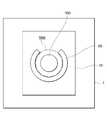
図1は、特定レジストの膜が規制部材に囲まれた領域内に配置されている状態の一実施形態を示す概略断面図であり、図2A、図2B、及び図2Cは、図1に示す規制部材の層構成を説明するための概略平面図である。
図1に示すように、特定レジスト100の膜は、基板1の面上に設けられた規制部材2に囲まれた領域内に配置されている。規制部材2は、両面粘着シート3を介して基板1の面上に固定されている。規制部材2は、図2Aに示すPETシート10、図2Bに示す枠状の両面粘着シート20、及び図2Cに示す枠状のPETシート30が、この順で積層されて形成されている。枠状の両面粘着シート20及び枠状のPETシート30の合計膜厚は、特定レジスト100の膜厚よりも厚くなっている。このため、特定レジスト100の流出を制限できる。枠状の両面粘着シート20及び枠状のPETシート30は、B工程の後、C工程における熱プレスを行う前に剥離される。
例えば、大きさが65mm×48mmであり、膜厚が300μmであるレジスト膜を形成する場合、PETシート10のある一態様は、大きさが150mm×100mmであり、膜厚が250μmであり、両面粘着シート20のある一態様は、外径が110mm×80mmであり、内径が80mm×60mmであり、膜厚が210μmであり、PETシート30のある一態様は、外径が110mm×80mmであり、内径が80mm×60mmであり、膜厚が250μmである。A preferred embodiment of the restricting member will be described with reference to FIGS. 1, 2A, 2B, and 2C.
FIG. 1 is a schematic cross-sectional view showing an embodiment in which a specific resist film is arranged in a region surrounded by a regulating member, and FIGS. 2A, 2B, and 2C are shown in FIG. FIG. 4 is a schematic plan view for explaining the layer structure of the regulation member;
As shown in FIG. 1, the film of the specific resist 100 is arranged within a region surrounded by the regulation members 2 provided on the surface of the
For example, when forming a resist film with a size of 65 mm × 48 mm and a film thickness of 300 µm, one aspect of the
工程Bでは、特定レジストの膜に対し、熱処理を行う。
熱処理の手段は、特に限定されない。
熱処理の手段としては、例えば、ホットプレート、コンベクションオーブン(所謂、熱風循環式乾燥機)が挙げられる。また、真空環境下における熱処理の手段としては、例えば、真空加熱乾燥機が挙げられる。In step B, heat treatment is performed on the specific resist film.
The means of heat treatment is not particularly limited.
Examples of heat treatment means include a hot plate and a convection oven (so-called hot air circulation dryer). Moreover, as means for heat treatment in a vacuum environment, for example, a vacuum heating dryer is exemplified.
熱処理の温度は、特に限定されず、例えば、特定レジストの種類に応じて適宜設定される。例えば、23℃における粘度が5000mPa・s以下である特定レジストの場合、熱処理の温度は、熱処理により特定レジストの粘度が下がる温度に設定される。
熱処理の温度は、例えば、50℃以上であることが好ましく、55℃以上であることがより好ましく、60℃以上であることが更に好ましく、65℃以上であることが特に好ましい。また、熱処理の温度は、例えば、130℃以下であることが好ましく、120℃以下であることがより好ましく、110℃以下であることが更に好ましい。The heat treatment temperature is not particularly limited, and is appropriately set according to the type of specific resist, for example. For example, in the case of a specific resist having a viscosity of 5000 mPa·s or less at 23° C., the heat treatment temperature is set to a temperature at which the viscosity of the specific resist is lowered by the heat treatment.
The heat treatment temperature is, for example, preferably 50° C. or higher, more preferably 55° C. or higher, even more preferably 60° C. or higher, and particularly preferably 65° C. or higher. The temperature of the heat treatment is, for example, preferably 130° C. or lower, more preferably 120° C. or lower, and even more preferably 110° C. or lower.
23℃における特定レジストの粘度が5000mPa・sを超える場合、工程Bでは、特定レジストの膜の温度を段階的に又は連続的に上げることにより、特定レジストの粘度を5000mPa・s以下にすることが好ましい。
特定レジストの膜の温度を段階的に又は連続的に上げると、急激な温度上昇に起因する膜中での気泡の発生を抑制できる。また、特定レジストの粘度を5000mPa・s以下にすると、膜中の気泡を除去しやすくなる。
特定レジストの膜の温度は、段階的に上げてもよく、連続的に上げてもよいが、段階的に上げることがより好ましい。
特定レジストの膜の温度を段階的に上げる場合、段階数は、2段階以上であれば、特に限定されない。例えば、操作の煩雑さを低減する観点から、段階数は、5段階以下であることが好ましく、2段階であることが特に好ましい。
特定レジストの膜の温度を段階的に上げる場合、例えば、特定レジストの膜の温度を50℃~70℃に上げた後、90℃~130℃に上げる態様が好ましく、特定レジストの膜の温度を55℃~70℃に上げた後、90℃~120℃に上げる態様がより好ましく、特定レジストの膜の温度を60℃~70℃に上げた後、90℃~110℃に上げる態様が更に好ましい。
各段階での加熱時間は、特に限定されないが、最終段階での加熱時間が最も長いことが好ましい。When the viscosity of the specific resist at 23° C. exceeds 5000 mPa·s, in step B, the temperature of the film of the specific resist is increased stepwise or continuously to make the viscosity of the specific resist 5000 mPa·s or less. preferable.
Raising the temperature of the specific resist film stepwise or continuously can suppress the generation of air bubbles in the film due to a rapid temperature rise. Further, when the viscosity of the specific resist is set to 5000 mPa·s or less, air bubbles in the film can be easily removed.
The temperature of the specific resist film may be raised stepwise or continuously, but is more preferably raised stepwise.
When the temperature of the film of the specific resist is raised stepwise, the number of steps is not particularly limited as long as it is two or more steps. For example, from the viewpoint of reducing the complexity of the operation, the number of stages is preferably 5 or less, particularly preferably 2.
When the temperature of the specific resist film is increased stepwise, for example, it is preferable to raise the temperature of the specific resist film to 50° C. to 70° C. and then to 90° C. to 130° C., and the temperature of the specific resist film is increased. More preferably, the temperature of the specific resist film is raised to 55 to 70°C and then raised to 90 to 120°C, and further preferably, the temperature of the specific resist film is raised to 60 to 70°C and then raised to 90 to 110°C. .
The heating time in each stage is not particularly limited, but the longest heating time in the final stage is preferred.
特定レジストの膜の温度を連続的に上げる場合、昇温速度は、特に限定されないが、例えば、70℃/分以下であることが好ましく、50℃/分以下であることがより好ましく、30℃/分以下であることが更に好ましい。
昇温速度の下限は、例えば、5℃/分以上であることが好ましい。When the temperature of the film of the specific resist is raised continuously, the rate of temperature rise is not particularly limited, but for example, it is preferably 70°C/min or less, more preferably 50°C/min or less, and 30°C. / minute or less is more preferable.
It is preferable that the lower limit of the heating rate is, for example, 5° C./min or more.
本開示において、レジストの膜の温度は、放射温度計を用いて測定されるレジストの膜面の温度をいう。放射温度計としては、例えば、アズワン(株)製の放射温度計(型番:IT-314)を用いることができる。但し、放射温度計は、これに限定されない。 In the present disclosure, the temperature of the resist film refers to the temperature of the resist film surface measured using a radiation thermometer. As the radiation thermometer, for example, a radiation thermometer (model number: IT-314) manufactured by AS ONE Corporation can be used. However, the radiation thermometer is not limited to this.
本開示において、膜を形成しているレジストの粘度は、以下の(1)~(3)の手順に従って求める。
(1)事前に、工程Aにおいて基板上に付与するレジストの温度と粘度との関係を示す校正曲線(「温度-粘度曲線」ともいう。)を作成する。具体的には、レジストの温度を23℃から153℃まで、10℃ずつ段階的に変化させながら、各段階の温度におけるレジストの粘度を、粘度計を用いて測定し、得られた値に基づいて、温度-粘度曲線を作成する。
(2)レジストの膜の温度を、放射温度計を用いて測定する。
(3)測定したレジストの膜の温度を、事前に作成した上記温度-粘度曲線にあてはめることにより、レジストの膜の粘度を求める。In the present disclosure, the viscosity of the resist forming the film is obtained according to the following procedures (1) to (3).
(1) Prepare in advance a calibration curve (also referred to as a “temperature-viscosity curve”) showing the relationship between the temperature and viscosity of the resist applied on the substrate in step A. Specifically, while changing the temperature of the resist from 23 ° C. to 153 ° C. in steps of 10 ° C., the viscosity of the resist at each temperature was measured using a viscometer, and based on the obtained value to create a temperature-viscosity curve.
(2) The temperature of the resist film is measured using a radiation thermometer.
(3) The viscosity of the resist film is obtained by applying the measured temperature of the resist film to the temperature-viscosity curve prepared in advance.
上記(1)における粘度計としては、例えば、サーモフィッシャーサイエンティフィック(株)製のレオメータ(商品名:HAAKE RheoStress 6000)を用いることができる。但し、粘度計は、これに限定されない。 As the viscometer in (1) above, for example, a rheometer (trade name: HAAKE RheoStress 6000) manufactured by Thermo Fisher Scientific Co., Ltd. can be used. However, the viscometer is not limited to this.
熱処理の時間は、特に限定されず、例えば、特定レジストの種類及び熱処理の温度に応じて適宜設定される。
熱処理の時間は、例えば、4時間~9時間であることが好ましく、4時間~8時間であることがより好ましく、5時間~8時間であることが更に好ましく、5時間~7時間であることが特に好ましい。The heat treatment time is not particularly limited, and is appropriately set, for example, according to the type of specific resist and the temperature of the heat treatment.
The heat treatment time is, for example, preferably 4 to 9 hours, more preferably 4 to 8 hours, even more preferably 5 to 8 hours, and 5 to 7 hours. is particularly preferred.
工程Bでは、粘度が5000mPa・s以下である特定レジストの膜に対し、真空環境下で熱処理を行うことが好ましい。
本開示において、「真空」とは、真空度が0.1MPa以下である状態をいう。In step B, the specific resist film having a viscosity of 5000 mPa·s or less is preferably heat-treated in a vacuum environment.
In the present disclosure, "vacuum" refers to a state in which the degree of vacuum is 0.1 MPa or less.
粘度の高いレジストの膜では、一度膜中に気泡が混入すると、気泡が抜け難い傾向がある。これに対し、レジストの粘度が5000mPa・s以下であると、膜中の気泡が移動しやすくなるため、膜から抜けやすくなる傾向がある。また、一般に、真空環境下では、気泡の体積が増えて膨張し、気泡の浮力が増加するため、大気圧下よりも気泡が膜から抜けやすい。
粘度が5000mPa・s以下である特定レジストの膜に対し、真空環境下で熱処理を行うと、気泡が抜けやすい状態で特定レジストが真空脱泡されるため、気泡がより低減されたレジスト膜の形成を実現し得る。
このような観点から、工程Bでは、粘度が5000mPa・s以下、好ましくは4000mPa・s以下、より好ましくは3000mPa・s以下、更に好ましくは2000mPa・s以下、特に好ましくは1000mPa・s以下である特定レジストの膜に対し、真空環境下で熱処理を行うことが望ましい。In a highly viscous resist film, once air bubbles are mixed in the film, they tend to be difficult to escape. On the other hand, when the viscosity of the resist is 5000 mPa·s or less, the air bubbles in the film tend to move easily and easily escape from the film. In general, in a vacuum environment, the volume of bubbles increases and expands, and the buoyancy of the bubbles increases.
When a specific resist film with a viscosity of 5000 mPa s or less is heat-treated in a vacuum environment, the specific resist is vacuum degassed in a state where air bubbles are easily removed, resulting in the formation of a resist film with further reduced air bubbles. can be realized.
From such a viewpoint, in the step B, the viscosity is 5000 mPa s or less, preferably 4000 mPa s or less, more preferably 3000 mPa s or less, still more preferably 2000 mPa s or less, and particularly preferably 1000 mPa s or less. It is desirable to heat-treat the resist film in a vacuum environment.
真空環境下で熱処理を行う場合の熱処理の温度は、特定レジストの粘度を5000mPa・s以下に保持できる温度であれば、特に限定されない。
真空環境下で熱処理を行う場合の熱処理の温度は、例えば、70℃~130℃であることが好ましく、90℃~130℃であることがより好ましく、90℃~120℃であることが更に好ましく、90℃~110℃であることが特に好ましい。The heat treatment temperature when the heat treatment is performed in a vacuum environment is not particularly limited as long as the temperature can keep the viscosity of the specific resist at 5000 mPa·s or less.
When heat treatment is performed in a vacuum environment, the heat treatment temperature is, for example, preferably 70°C to 130°C, more preferably 90°C to 130°C, and even more preferably 90°C to 120°C. , 90° C. to 110° C. is particularly preferred.
真空環境下で熱処理を行う場合の熱処理の時間は、特に限定されないが、例えば、1分以上であることが好ましく、2分以上であることがより好ましく、3分以上であることが更に好ましく、4分以上であることが特に好ましい。
上限は、特に限定されないが、例えば、10分以下であることが好ましい。The heat treatment time when heat treatment is performed in a vacuum environment is not particularly limited, but is preferably 1 minute or longer, more preferably 2 minutes or longer, and even more preferably 3 minutes or longer. 4 minutes or more is particularly preferred.
Although the upper limit is not particularly limited, it is preferably 10 minutes or less, for example.
工程Bでは、真空環境下で熱処理を行った特定レジストの膜に対し、大気圧下で熱処理を行うことが好ましい。
本開示において、「大気圧下」とは、0.1MPaを超えて0.12MPa以下の範囲を意味する。
特定レジストの膜に対して真空環境下で熱処理を行うと、特定レジストの粘度が比較的高いため、気泡が抜ける際にはじけることにより生じた痕が、膜の表面に残ったままの状態になることがある。真空環境下で熱処理を行った特定レジストの膜に対し、大気圧下で熱処理を行うと、膜の表面がレベリングされ、平坦化される。また、真空環境下で熱処理を行った特定レジストの膜に対し、大気圧下で熱処理を行うことで、特定レジストの膜中の残留溶媒を除去することもできる。In step B, it is preferable to perform heat treatment under atmospheric pressure on the specific resist film that has been heat treated in a vacuum environment.
In the present disclosure, "atmospheric pressure" means a range of more than 0.1 MPa to 0.12 MPa or less.
When a film of a specific resist is heat-treated in a vacuum environment, traces caused by popping when bubbles are removed from the film remain on the surface of the film due to the relatively high viscosity of the specific resist. Sometimes. When a specific resist film that has been heat-treated in a vacuum environment is heat-treated under atmospheric pressure, the surface of the film is leveled and flattened. Further, the residual solvent in the specific resist film can be removed by performing heat treatment under atmospheric pressure on the specific resist film that has been heat-treated in a vacuum environment.
真空環境下で熱処理を行った後、大気圧下で熱処理を行う場合の熱処理の温度は、特に限定されないが、例えば、70℃~130℃であることが好ましく、90℃~130℃であることがより好ましく、90℃~120℃であることが更に好ましく、90℃~110℃であることが特に好ましい。
真空環境下で熱処理を行った後、大気圧下で熱処理を行う場合の熱処理の温度は、例えば、真空環境下で行った熱処理の温度以上であることが好ましく、真空環境下で行った熱処理の温度と同じであることがより好ましい。The temperature of the heat treatment when the heat treatment is performed under atmospheric pressure after the heat treatment in a vacuum environment is not particularly limited. is more preferred, 90°C to 120°C is even more preferred, and 90°C to 110°C is particularly preferred.
When heat treatment is performed under atmospheric pressure after heat treatment in a vacuum environment, the temperature of the heat treatment is preferably, for example, the temperature of the heat treatment performed in the vacuum environment or higher. More preferably, it is the same as the temperature.
真空環境下で熱処理を行った後、大気圧下で熱処理を行う時間は、特に限定されないが、例えば、3時間以上であることが好ましく、3時間~8時間であることがより好ましく、4時間~7時間であることが更に好ましく、4時間~6時間であることが特に好ましい。 The time for heat treatment under atmospheric pressure after heat treatment in a vacuum environment is not particularly limited, but for example, it is preferably 3 hours or more, more preferably 3 hours to 8 hours, and 4 hours. ∼7 hours is more preferable, and 4 to 6 hours is particularly preferable.
〔工程C〕
工程Cは、特定レジストの膜を所望の厚さに調整する調整部材の設置により形成された領域内に配置された、熱処理後の特定レジストの膜に対し、シートを介して、熱プレスを行う工程である。
以下では、「特定レジストの膜を所望の厚さに調整する調整部材」を単に「調整部材」ともいう。[Step C]
In step C, the specific resist film after the heat treatment, which is arranged in the region formed by the installation of the adjusting member for adjusting the specific resist film to a desired thickness, is subjected to heat pressing through the sheet. It is a process.
Hereinafter, the "adjustment member for adjusting the thickness of the specific resist film to a desired thickness" is also simply referred to as the "adjustment member".
工程Cにおいて、工程Bを経た熱処理後の特定レジストの膜は、調整部材の設置により形成された領域内に配置されている。
調整部材は、熱処理後の特定レジストの膜に対して熱プレスを行う時点で、基板上に設置されていればよい。In the process C, the specific resist film after the heat treatment in the process B is arranged in the region formed by setting the adjusting member.
The adjustment member may be placed on the substrate at the time when the specific resist film after the heat treatment is hot pressed.
調整部材の材質は、特に限定されない。
調整部材の材質としては、例えば、金属、ガラス、及び樹脂が挙げられる。
これらの中でも、調整部材の材質としては、例えば、破損又は変形が生じ難いという観点から、金属が好ましい。
金属としては、例えば、ステンレス鋼(SUS)、鉄、銅、及びアルミニウムが挙げられる。
これらの中でも、金属としては、ステンレス鋼(SUS)が好ましい。The material of the adjusting member is not particularly limited.
Examples of materials for the adjustment member include metal, glass, and resin.
Among these, metal is preferable as the material of the adjusting member, for example, from the viewpoint of being less likely to be damaged or deformed.
Metals include, for example, stainless steel (SUS), iron, copper, and aluminum.
Among these, stainless steel (SUS) is preferable as the metal.
調整部材の形状は、特に限定されないが、シートを安定に配置できる形状、具体的には、シートを熱処理後の特定レジストの膜に対して平行な状態で安定に支えることが可能な形状であることが好ましい。
調整部材の形状としては、例えば、柱状(例えば、円柱状及び角柱状)、馬蹄形状等の形状が挙げられる。The shape of the adjustment member is not particularly limited, but it should be a shape that allows the sheet to be stably arranged, specifically, a shape that can stably support the sheet in parallel with the specific resist film after the heat treatment. is preferred.
Examples of the shape of the adjusting member include a columnar shape (for example, a columnar shape and a prismatic shape), a horseshoe shape, and the like.
調整部材の高さは、熱処理後の特定レジストの膜の膜厚よりも低いことが好ましい。調整部材の高さが熱処理後の特定レジストの膜の膜厚よりも低いと、面内の膜厚変動がより小さいレジスト膜を形成できる傾向がある。 The height of the adjusting member is preferably lower than the film thickness of the specific resist film after the heat treatment. When the height of the adjusting member is lower than the film thickness of the specific resist film after the heat treatment, there is a tendency that a resist film with less in-plane film thickness variation can be formed.
調整部材と、熱処理後の特定レジストの膜とは、面内方向に間隔をあけて設置されていることが好ましい。
間隔は、特に限定されないが、例えば、5mm~30mmであることが好ましく、10mm~20mmであることがより好ましい。
間隔が5mm以上であると、例えば、熱プレスによって粘度が低下した特定レジストが、基板又は基材と、調整部材との隙間に入り込むといった不具合がより生じ難い傾向がある。
間隔が30mm以下であると、例えば、熱プレスの際に使用するシートの中心部のたわみに起因するレジスト膜の面内の膜厚変動が生じ難い傾向がある。It is preferable that the adjusting member and the film of the specific resist after the heat treatment are spaced apart in the in-plane direction.
Although the interval is not particularly limited, it is preferably 5 mm to 30 mm, more preferably 10 mm to 20 mm.
If the gap is 5 mm or more, for example, there is a tendency that the specific resist whose viscosity has been lowered by hot pressing does not easily enter the gap between the substrate or base material and the adjustment member.
If the interval is 30 mm or less, for example, there is a tendency that in-plane film thickness variation of the resist film due to bending of the central portion of the sheet used in hot pressing is less likely to occur.
調整部材の設置により形成された領域は、調整部材の設置により完全に閉鎖された領域ではなく、少なくとも一部が開放された領域であることが好ましい。調整部材の設置により形成された領域の少なくとも一部が開放されていると、熱プレスを行った際に、余剰の特定レジストを開放部から流出させることができる。このため、特定レジストの膜の厚さを所望の厚さにより調整しやすくなる傾向がある。 The area formed by the installation of the adjustment member is preferably an at least partially open area rather than a completely closed area by the installation of the adjustment member. If at least a portion of the region formed by setting the adjusting member is open, excess specific resist can flow out from the open portion when hot pressing is performed. Therefore, it tends to be easier to adjust the thickness of the specific resist film to a desired thickness.
調整部材は、基板上に固定されていることが好ましい。
基板上に調整部材を固定する手段は、特に限定されないが、調整部材の固定が不要となった時点で、基板上から調整部材を取り除くことができる手段であることが好ましい。このような観点から、基板上に調整部材を固定する手段としては、例えば、粘着剤、両面粘着シート等の剥離可能な固定手段が挙げられる。Preferably, the adjustment member is fixed on the substrate.
The means for fixing the adjusting member on the substrate is not particularly limited, but it is preferable that the means is capable of removing the adjusting member from the substrate when it becomes unnecessary to fix the adjusting member. From this point of view, the means for fixing the adjustment member on the substrate includes, for example, a peelable fixing means such as an adhesive and a double-sided adhesive sheet.
図3、図4、及び図5を参照して、調整部材の好ましい態様を説明する。
図3は、調整部材40として形状が角柱状(詳細には、直方体状)であるステンレス鋼材(SUS)を用いた場合において、熱処理後の特定レジストの膜が調整部材の設置により形成された領域内に配置されている状態の一実施形態を示す概略平面図であり、図4は、調整部材40として形状が馬蹄形であるステンレス鋼材(SUS)を用いた場合において、熱処理後の特定レジストの膜が調整部材の設置により形成された領域内に配置されている状態の他の実施形態を示す概略平面図であり、図5は、調整部材40として形状が円柱状であるステンレス鋼材(SUS)を用いた場合において、熱処理後の特定レジストの膜が調整部材の設置により形成された領域内に配置されている状態の他の実施形態を示す概略平面図である。
図3、図4、及び図5に示すように、調整部材40は、基板1の面上に設けられたPETシート10(即ち、図1に示す規制部材2の一部をなす部材)の面上に設置され、調整部材40の設置により形成された領域内に、熱処理後の特定レジスト100の膜が配置されている。「調整部材40の設置により形成された領域」とは、1つの調整部材40によって囲まれた領域、又は、複数の調整部材40によって挟まれた領域のことであり、また、例えば、図3に示す2つの調整部材40によって挟まれた領域50A、図4に示す1つの調整部材40によって囲まれた領域50B、及び図5に示す4つの調整部材40によって挟まれた領域50Cのような、想像線(二点破線)に囲まれた領域でもよい。
図3、図4、及び図5において、調整部材40と、熱処理後の特定レジスト100の膜とは、面内方向に間隔をあけて設置されている。このような設置態様によれば、熱プレスによって粘度が低下した特定レジスト100が、基板1又はPETシート10と、調整部材40との隙間に入り込むといった不具合が生じ難い傾向がある。また、図3、図4、及び図5において、調整部材40の設置により形成された領域は、完全に閉鎖された領域ではなく、少なくとも一部に開放部を有している。このような態様によれば、余剰の特定レジスト100を開放部から流出させることができるため、特定レジスト100の膜の厚さを所望の厚さにより調整しやすくなる傾向がある。A preferred embodiment of the adjustment member will now be described with reference to FIGS. 3, 4 and 5. FIG.
FIG. 3 shows a region in which a film of a specific resist after heat treatment is formed by installing the adjustment member when a stainless steel material (SUS) having a prismatic shape (specifically, a rectangular parallelepiped shape) is used as the
As shown in FIGS. 3, 4, and 5, the adjusting
In FIGS. 3, 4, and 5, the adjusting
熱処理後の特定レジストの膜への熱プレスは、シートを介して行う。
熱処理後の特定レジストの膜に対し、シートを介した熱プレスを行うと、例えば、シートを介しない場合と比較して、熱プレス後に特定レジストの膜を剥離しやすくなるため、剥離に起因する面内膜厚の変動が生じ難い傾向がある。
シートの材質は、特に限定されないが、例えば、樹脂であることが好ましい。
樹脂としては、例えば、ポリエチレンテレフタレート(PET)、ポリエチレンナフタレート(PEN)、ポリカーボネート(PC)、ポリイミド(PI)、及びトリアセチルセルロース(TAC)が挙げられる。
これらの中でも、樹脂としては、ポリエチレンテレフタレート(PET)が好ましい。The heat press to the film of the specific resist after the heat treatment is performed through the sheet.
When the specific resist film after heat treatment is hot pressed through a sheet, the specific resist film becomes easier to peel after hot pressing than when the sheet is not used. There is a tendency that variations in in-plane film thickness are less likely to occur.
Although the material of the sheet is not particularly limited, it is preferably resin, for example.
Resins include, for example, polyethylene terephthalate (PET), polyethylene naphthalate (PEN), polycarbonate (PC), polyimide (PI), and triacetyl cellulose (TAC).
Among these, polyethylene terephthalate (PET) is preferable as the resin.
シートとしては、市販品を使用できる。
市販品の例としては、東レ(株)製のルミラー(登録商標)シリーズ〔材質:二軸延伸PETフィルム〕が挙げられる。A commercially available product can be used as the sheet.
Examples of commercially available products include Lumirror (registered trademark) series (material: biaxially stretched PET film) manufactured by Toray Industries, Inc.
シートの形状は、特に限定されず、例えば、特定レジストの膜の形状に応じて適宜選択できる。 The shape of the sheet is not particularly limited, and can be appropriately selected according to, for example, the shape of the specific resist film.
シートの膜厚は、特に限定されないが、例えば、100μm~400μmであることが好ましく、200μm~250μmであることがより好ましい。
シートの膜厚が上記範囲内であると、熱プレス後に特定レジストの膜からの剥離がより容易となる傾向がある。Although the film thickness of the sheet is not particularly limited, it is preferably 100 μm to 400 μm, more preferably 200 μm to 250 μm.
When the film thickness of the sheet is within the above range, there is a tendency that the specific resist can be easily peeled off from the film after hot pressing.
本開示において、シートの膜厚は、シートの平均膜厚を意味する。
シートの平均膜厚は、以下の方法により求められる値である。
シートの厚み方向において、無作為に選択した10箇所で測定されるシートの膜厚の算術平均値を求め、得られた値をシートの平均膜厚とする。シートの膜厚の測定には、マイクロメータを用いる。マイクロメータとしては、例えば、(株)ミツトヨ製のマイクロメータ(商品名:クリンプハイトマイクロメータ)が挙げられる。但し、マイクロメータは、これに限定されない。In the present disclosure, the sheet thickness means the average thickness of the sheet.
The average film thickness of the sheet is a value obtained by the following method.
An arithmetic mean value of the film thickness of the sheet measured at 10 randomly selected points in the thickness direction of the sheet is obtained, and the obtained value is defined as the average film thickness of the sheet. A micrometer is used to measure the film thickness of the sheet. Examples of the micrometer include a micrometer manufactured by Mitutoyo Corporation (trade name: crimp height micrometer). However, the micrometer is not limited to this.
シートの熱処理後の特定レジストの膜側の面(以下、「シート表面」ともいう。)は、高い平坦性を有することが好ましい。
具体的には、シート表面の算術平均粗さRaは、例えば、10μm以下であることが好ましく、5μm以下であることがより好ましく、3μm以下であることが更に好ましく、1μm以下であることが特に好ましい。
シート表面の算術平均粗さRaが10μm以下であると、面内の膜厚変動がより小さいレジスト膜を形成できる傾向がある。It is preferable that the film-side surface of the specific resist after heat treatment of the sheet (hereinafter also referred to as "sheet surface") has high flatness.
Specifically, the arithmetic mean roughness Ra of the sheet surface is, for example, preferably 10 µm or less, more preferably 5 µm or less, even more preferably 3 µm or less, and particularly preferably 1 µm or less. preferable.
When the sheet surface has an arithmetic mean roughness Ra of 10 μm or less, there is a tendency to form a resist film with less in-plane film thickness variation.
本開示において、シート表面の算術平均粗さRaは、表面粗さ測定機を用いて測定される値である。
表面粗さ測定機としては、例えば、(株)キーエンス製のワンショット3D形状測定機(種類:ヘッド、型式:VR-5100)を用いることができる。但し、表面粗さ測定機は、これに限定されない。In the present disclosure, the arithmetic mean roughness Ra of the sheet surface is a value measured using a surface roughness measuring machine.
As the surface roughness measuring instrument, for example, a one-shot 3D shape measuring instrument manufactured by Keyence Corporation (type: head, model: VR-5100) can be used. However, the surface roughness measuring machine is not limited to this.
シートは、適度な弾性を有することが好ましい。
具体的には、シートのヤング率は、例えば、40MPa~5500MPaであることが好ましく、200MPa~5500MPaであることがより好ましく、1000MPa~5000MPaであることが更に好ましく、4000MPa~5000MPaであることが特に好ましい。
シートのヤング率が40MPa以上であると、シートがより適度に柔らかいため、熱プレス後に特定レジストの膜からの剥離がより容易となる傾向がある。
シートのヤング率が5500MPa以下であると、シートがより適度に硬いため、熱プレス後に特定レジストの膜からの剥離がより容易となる傾向がある。The sheet preferably has moderate elasticity.
Specifically, the Young's modulus of the sheet is, for example, preferably 40 MPa to 5500 MPa, more preferably 200 MPa to 5500 MPa, even more preferably 1000 MPa to 5000 MPa, particularly 4000 MPa to 5000 MPa. preferable.
When the Young's modulus of the sheet is 40 MPa or more, the sheet is moderately soft, so that the sheet tends to be more easily peeled off from the film of the specific resist after hot pressing.
When the Young's modulus of the sheet is 5500 MPa or less, the sheet tends to be more moderately hard, so that the specific resist tends to be easily peeled off from the film after hot pressing.
本開示において、シートのヤング率は、JIS K 7161-1:2014及びJIS K 7127:1999に基づく引張試験により求められる値である。 In the present disclosure, the Young's modulus of the sheet is a value determined by a tensile test based on JIS K 7161-1:2014 and JIS K 7127:1999.
例えば、面内の膜厚変動がより小さいレジスト膜の形成を実現する観点から、熱プレスは、特定レジストの膜とシートとの間に気泡が入らないように、特定レジストの膜の面とシートの面とを密着させた後、行うことが好ましい。
特定レジストの膜の面とシートの面とを密着させる手段は、特に限定されず、例えば、圧着ローラー、真空吸着機等を用いる手段が挙げられる。For example, from the viewpoint of realizing the formation of a resist film with smaller in-plane film thickness fluctuations, the heat press is applied to the surface of the specific resist film and the sheet so that air bubbles do not enter between the specific resist film and the sheet. It is preferable to carry out after contacting the surface of the
The means for bringing the specific resist film surface and the sheet surface into close contact is not particularly limited, and examples thereof include means using a pressure roller, a vacuum suction machine, and the like.
熱プレスの手段は、特に限定されない。
熱プレスの手段としては、例えば、ホットプレートと重石との組み合わせ、及び熱プレス機が挙げられる。
荷重条件は、特に限定されないが、例えば、1.0N/cm2以上であることが好ましく、1.0N/cm2~2.0N/cm2であることがより好ましい。A means of hot pressing is not particularly limited.
Hot pressing means include, for example, a combination of a hot plate and weights, and a hot press machine.
Although the load condition is not particularly limited, for example, it is preferably 1.0 N/cm2 or more, more preferably 1.0 N/cm2 to 2.0 N/cm2 .
熱プレスの温度は、特に限定されないが、例えば、60℃~120℃であることが好ましく、60℃~110℃であることがより好ましく、60℃~100℃であることが更に好ましく、60℃~90℃であることが特に好ましい。 The temperature of the hot press is not particularly limited, but for example, it is preferably 60°C to 120°C, more preferably 60°C to 110°C, even more preferably 60°C to 100°C, and 60°C. ~90°C is particularly preferred.
熱プレスの温度は、工程Bにおける熱処理の温度よりも低いことが好ましい。熱プレスの温度が高すぎると、熱処理後の特定レジストの膜中に気泡が発生することがある。熱プレスの温度が工程Bにおける熱処理の温度よりも低いと、熱プレスの温度に起因する気泡の発生を抑制し得る。 The temperature of the hot press is preferably lower than the temperature of the heat treatment in step B. If the hot press temperature is too high, air bubbles may be generated in the specific resist film after the heat treatment. When the temperature of the hot press is lower than the temperature of the heat treatment in step B, the generation of air bubbles due to the temperature of the hot press can be suppressed.
熱プレスの時間は、特に限定されないが、例えば、10分間~60分間であることが好ましく、15分間~50分間であることがより好ましく、20分間~40分間であることが更に好ましい。 The heat pressing time is not particularly limited, but is preferably, for example, 10 to 60 minutes, more preferably 15 to 50 minutes, and even more preferably 20 to 40 minutes.
〔その他の工程〕
本開示のレジスト膜の形成方法は、本開示の効果を損なわない範囲において、必要に応じて、工程A、工程B、及び工程C以外の工程(所謂、その他の工程)を含んでいてもよい。[Other processes]
The method for forming a resist film of the present disclosure may optionally include steps other than steps A, B, and C (so-called other steps) as long as the effects of the present disclosure are not impaired. .
その他の工程としては、例えば、熱プレス後の特定レジストの膜の温度を段階的に又は連続的に下げる工程(所謂、冷却工程)が挙げられる。
熱プレス後の特定レジストの膜の温度を急激に下げると、特定レジストの膜の内部に応力が発生し、レジスト膜の面内の膜厚変動に影響が生じ得る。このため、熱プレス後の特定レジストの膜の温度は、段階的に又は連続的に低下(所謂、徐冷)させることが好ましく、連続的に低下させることがより好ましい。
熱プレス後の特定レジストの膜の温度を連続的に低下させる場合、降温速度は、特に限定されないが、例えば、5℃/分以下であることが好ましく、4℃/分以下であることがより好ましく、3℃/分以下であることが更に好ましい。
降温速度の下限は、例えば、0.1℃/分以上であることが好ましい。
冷却後の特定レジストの膜の温度は、特に限定されないが、例えば、5℃~30℃であることが好ましく、10℃~25℃であることがより好ましく、15℃~23℃であることが更に好ましい。Other steps include, for example, a step of stepwise or continuously lowering the temperature of the specific resist film after hot pressing (so-called cooling step).
If the temperature of the specific resist film after hot pressing is rapidly lowered, stress is generated inside the specific resist film, which may affect the in-plane film thickness variation of the resist film. For this reason, the temperature of the specific resist film after hot pressing is preferably lowered stepwise or continuously (so-called slow cooling), and more preferably lowered continuously.
When the temperature of the specific resist film after hot pressing is continuously lowered, the rate of temperature drop is not particularly limited, but for example, it is preferably 5° C./min or less, more preferably 4° C./min or less. It is preferably 3° C./min or less, more preferably 3° C./min or less.
The lower limit of the temperature drop rate is preferably 0.1° C./min or more, for example.
The temperature of the specific resist film after cooling is not particularly limited. More preferred.
また、例えば、特定レジストが光硬化性である場合には、その他の工程としては、冷却工程後の特定レジストの膜に対して光照射を行う工程(所謂、露光工程)が挙げられる。
光源の具体例としては、各種レーザ、発光ダイオード(LED)、超高圧水銀灯、高圧水銀灯、メタルハライドランプ等が挙げられる。
露光量(所謂、積算光量)は、特に限定されず、例えば、特定レジストの種類に応じて適宜設定できる。
また、その他の工程としては、例えば、現像工程、ポストベーク工程等の工程が挙げられる。Further, for example, when the specific resist is photocurable, the other process includes a process of irradiating the film of the specific resist after the cooling process with light (so-called exposure process).
Specific examples of light sources include various lasers, light-emitting diodes (LEDs), ultrahigh-pressure mercury lamps, high-pressure mercury lamps, metal halide lamps, and the like.
The amount of exposure (so-called integrated amount of light) is not particularly limited, and can be set appropriately according to the type of specific resist, for example.
Moreover, as other processes, processes, such as a developing process and a post-baking process, are mentioned, for example.
[レジスト膜]
本開示のレジスト膜は、本開示のレジスト膜の形成方法により形成されたレジスト膜であって、膜厚が300μm以上であり、かつ、面内の膜厚変動が10%以内である。
本開示のレジスト膜の形成方法は、既述のとおりである。
本開示のレジスト膜は、例えば、膜厚が300μm以上であり、かつ、面内の膜厚変動が8%以内であることが好ましく、膜厚が300μm以上であり、かつ、面内の膜厚変動が6%以内であることがより好ましく、膜厚が300μm以上であり、かつ、面内の膜厚変動が4%以内であることが更に好ましく、膜厚が300μm以上であり、かつ、面内の膜厚変動が2%以内であることが特に好ましい。[Resist film]
The resist film of the present disclosure is a resist film formed by the method of forming a resist film of the present disclosure, has a film thickness of 300 μm or more, and has an in-plane film thickness variation of 10% or less.
The method of forming the resist film of the present disclosure is as described above.
The resist film of the present disclosure, for example, preferably has a film thickness of 300 μm or more and an in-plane film thickness variation of 8% or less, and has a film thickness of 300 μm or more and an in-plane film thickness of It is more preferable that the variation is within 6%, the film thickness is 300 μm or more, and the in-plane film thickness variation is further preferably within 4%. It is particularly preferable that the inner film thickness variation is within 2%.
本開示において、レジスト膜の膜厚は、レジスト膜の平均膜厚を意味する。
レジスト膜の平均膜厚は、以下の方法により求められる値である。
レジスト膜の厚み方向において、無作為に選択した10箇所で測定されるレジスト膜の膜厚の算術平均値を求め、得られた値をレジスト膜の平均膜厚とする。レジスト膜の膜厚の測定には、レーザ変位計を用いる。レーザ変位計としては、例えば、(株)キーエンス製の分光干渉レーザ変位計(型式:SI-F10)が挙げられる。但し、レーザ変位計は、これに限定されない。In the present disclosure, the film thickness of the resist film means the average film thickness of the resist film.
The average film thickness of the resist film is a value obtained by the following method.
An arithmetic average value of thicknesses of the resist film measured at 10 randomly selected locations in the thickness direction of the resist film is obtained, and the obtained value is defined as the average thickness of the resist film. A laser displacement gauge is used to measure the film thickness of the resist film. As a laser displacement meter, for example, a spectral interference laser displacement meter (model: SI-F10) manufactured by Keyence Corporation can be used. However, the laser displacement gauge is not limited to this.
レジスト膜の面内の膜厚変動は、レジスト膜の厚み方向において、無作為に選択した10箇所で測定されるレジスト膜の膜厚の最大値及び最小値、並びに、上記にて求めたレジスト膜の平均膜厚から、以下の計算式により求められる値である。
レジスト膜の面内の膜厚変動(単位:%)=[レジスト膜の膜厚の最大値(単位:μm)-レジスト膜の膜厚の最小値(単位:μm)]/レジスト膜の平均膜厚(単位:μm)×100
例えば、無作為に選択した10箇所で測定されるレジスト膜の膜厚が、それぞれ300μm、300μm、305μm、305μm、310μm、310μm、315μm、315μm、320μm、及び320μmである場合、レジスト膜の平均膜厚は、310μmであり、レジスト膜の面内の膜厚変動は、約6.5%である。The in-plane film thickness variation of the resist film is the maximum and minimum values of the film thickness of the resist film measured at 10 randomly selected locations in the thickness direction of the resist film, and the resist film obtained above. It is a value obtained by the following formula from the average film thickness of .
In-plane film thickness variation of resist film (unit: %) = [maximum value of resist film thickness (unit: μm) - minimum value of resist film thickness (unit: μm)] / average film thickness of resist film Thickness (unit: μm) × 100
For example, when the film thickness of the resist film measured at 10 randomly selected locations is 300 μm, 300 μm, 305 μm, 305 μm, 310 μm, 310 μm, 315 μm, 315 μm, 320 μm, and 320 μm, the average film thickness of the resist film The thickness is 310 μm, and the in-plane film thickness variation of the resist film is about 6.5%.
以下、本開示のレジスト膜の形成方法及びレジスト膜を実施例により更に具体的に説明する。但し、本開示のレジスト膜の形成方法及びレジスト膜は、その主旨を越えない限り、以下の実施例に限定されるものではない。 Hereinafter, the method for forming a resist film and the resist film of the present disclosure will be described more specifically with reference to examples. However, the method of forming a resist film and the resist film of the present disclosure are not limited to the following examples as long as they do not exceed the gist thereof.
以下の実施例において、レジスト膜の膜厚及び面内の膜厚変動は、既述の方法により求めた。なお、測定装置には、(株)キーエンス製の分光干渉レーザ変位計(型式:SI-F10)を用いた。 In the following examples, the film thickness of the resist film and the in-plane film thickness variation were determined by the method described above. A spectroscopic interference laser displacement meter (type: SI-F10) manufactured by KEYENCE CORPORATION was used as a measuring device.
レジストの粘度は、サーモフィッシャーサイエンティフィック(株)製のレオメータ(商品名:HAAKE RheoStress 6000)を用いて測定した。 The viscosity of the resist was measured using a rheometer (trade name: HAAKE RheoStress 6000) manufactured by Thermo Fisher Scientific Co., Ltd.
レジストの膜の温度は、アズワン(株)製の放射温度計(型番:IT-314)を用いて測定した。
膜を形成しているレジストの粘度は、既述の方法により求めた。すなわち、以下の実施例で使用するレジストの温度と粘度との関係を示す校正曲線(即ち、温度-粘度曲線)をあらかじめ作成し、上記放射温度計を用いて測定したレジストの膜の温度を、作成した温度-粘度曲線にあてはめることにより、膜を形成しているレジストの粘度を求めた。The temperature of the resist film was measured using a radiation thermometer (model number: IT-314) manufactured by AS ONE Corporation.
The viscosity of the resist forming the film was determined by the method described above. That is, a calibration curve (that is, a temperature-viscosity curve) showing the relationship between the temperature and viscosity of the resist used in the following examples was prepared in advance, and the temperature of the resist film measured using the radiation thermometer was The viscosity of the resist forming the film was obtained by applying the prepared temperature-viscosity curve.
[レジスト膜の形成]
〔実施例1〕
-工程A-
基板〔商品名:SMS6025E2、サイズ:6025(大きさ:152mm×152mm、厚さ:6.35mm)、材質:合成石英ガラス、信越化学工業(株)製〕の一方の面上に、規制部材である3層構造を有する凹型形状のPETシート、詳細には、図1及び図2に示すPETシート10/両面粘着シート20/PETシート30の積層構造を有する凹型形状の規制部材2を、両面粘着シートを用いて貼り付けた。PET10は、大きさが150mm×100mmであり、膜厚が250μmであり、両面粘着シート20は、外径が110mm×80mmであり、内径が80mm×60mmであり、膜厚が210μmであり、PET30は、外径が110mm×80mmであり、内径が80mm×60mmであり、膜厚が250μmである。次いで、上記PETシートの凹部に、特定レジストとしてのSU-8 3050〔商品名、23℃における粘度:12000mPa・s、日本化薬(株)製〕を460μmの厚さにスリット塗布し、特定レジストの膜を形成した。形成された特定レジストの膜は、規制部材に囲まれた領域内に配置されている。[Formation of resist film]
[Example 1]
-Step A-
On one side of the substrate [trade name: SMS6025E2, size: 6025 (size: 152 mm × 152 mm, thickness: 6.35 mm), material: synthetic quartz glass, manufactured by Shin-Etsu Chemical Co., Ltd.] A concave-shaped PET sheet having a three-layer structure, more specifically, a concave-shaped regulating member 2 having a laminated structure of
-工程B-
次に、上記にて形成した特定レジストの膜に対し、熱処理を行った。具体的には、以下の操作を行った。凹部に特定レジストの膜が配置されたPETシート付き基板を、加熱温度を70℃に設定したホットプレートの上に置き、30秒間加熱(所謂、第1段階目の加熱)した後、加熱温度を100℃に設定したホットプレートの上に移動させて、更に1時間加熱(所謂、第2段階目の加熱)することにより、特定レジストの膜の温度を段階的に昇温させた。
なお、第1段階目の加熱後の特定レジストの膜の温度は65℃であり、第2段階目の加熱後の特定レジストの膜の温度は95℃であり、第2段階目の加熱後の特定レジストの粘度は、4000mPa・sであった。
次いで、PETシート付き基板Xを、庫内の温度を100℃に設定した真空乾燥機〔商品名:ETTAS 真空乾燥機、型番:AVO-200NS-D、アズワン(株)製〕に入れ、5分間真空加熱した。なお、庫内の真空度は、0.1MPaであった。次いで、PETシート付き基板を真空乾燥機から取り出し、加熱温度を100℃に設定したホットプレートの上に置き、大気圧下で更に5時間加熱した。次いで、PETシート付き基板の両面粘着シート20及びPETシート30を剥離除去した。-Process B-
Next, heat treatment was performed on the specific resist film formed as described above. Specifically, the following operations were performed. A substrate with a PET sheet having a specific resist film arranged in the recess is placed on a hot plate set to a heating temperature of 70 ° C. and heated for 30 seconds (so-called first stage heating). The temperature of the specific resist film was increased stepwise by moving it onto a hot plate set at 100° C. and further heating for 1 hour (so-called second-stage heating).
The temperature of the specific resist film after the first stage heating was 65° C., the temperature of the specific resist film after the second stage heating was 95° C., and the temperature of the specific resist film after the second stage heating was 95° C. The specific resist had a viscosity of 4000 mPa·s.
Next, the substrate X with the PET sheet is placed in a vacuum dryer [trade name: ETTAS vacuum dryer, model number: AVO-200NS-D, manufactured by AS ONE Co., Ltd.] in which the temperature inside the chamber is set to 100 ° C., and is kept for 5 minutes. Vacuum heated. The degree of vacuum inside the chamber was 0.1 MPa. Then, the substrate with the PET sheet was taken out from the vacuum dryer, placed on a hot plate set at a heating temperature of 100° C., and heated under atmospheric pressure for 5 hours. Next, the double-
-工程C-
次に、上記にて熱処理を行った特定レジストの膜に対し、熱プレスを行った。具体的には、以下の操作を行った。
熱処理後の特定レジストの膜が配置されたPETシート10の面上に、目的とするレジスト膜の膜厚と同じ高さのシム板〔材質:SUS、大きさ:10mm×110mm、高さ:300μm、形状:直方体〕、詳細には、図3に示す調整部材40を、図3に示すように、特定レジストの膜と、面内方向に間隔(間隔:20mm)が空くように設置した。次いで、特定レジストの膜の面上に、シート〔材質:PET、大きさ:150mm×210mm、厚さ:250μm、シート表面の算術平均粗さRa:0.6μm、シートのヤング率:5000MPa〕を置いた後、ハンドローラーを用いて、特定レジストの膜とシートとを密着させた。次いで、特定レジストの膜に密着させたシートの上に、重さ6000gの重石を置き、特定レジストの膜に対し、1.2N/cm2の荷重をかけた後、基板ごと、80℃に加熱したホットプレートの上に置き、30分間加熱した。
なお、加熱後の特定レジストの膜の温度は75℃であった。-Process C-
Next, a hot press was performed on the specific resist film that had been heat-treated as described above. Specifically, the following operations were performed.
A shim plate having the same height as the desired resist film thickness [material: SUS, size: 10 mm × 110 mm, height: 300 µm , shape: rectangular parallelepiped] Specifically, the
The temperature of the specific resist film after heating was 75°C.
-その他の工程-
次に、ホットプレートから基板を取り出し、熱プレス後の特定レジストの膜を、6時間かけて23℃まで冷却した。なお、降温速度は、0.14℃/分である。冷却後、重石、シート、及びシム板を外した。
以上のようにして、レジスト膜を形成した。-Other processes-
Next, the substrate was removed from the hot plate, and the specific resist film after hot pressing was cooled to 23° C. over 6 hours. The temperature drop rate is 0.14° C./min. After cooling, the weight, sheet and shim plate were removed.
A resist film was formed as described above.
実施例1の方法により形成されたレジスト膜は、膜厚が300μmであり、面内の膜厚変動が5%であった。また、実施例1の方法により形成されたレジスト膜を目視にて観察したところ、気泡が全く確認されなかった。 The resist film formed by the method of Example 1 had a film thickness of 300 μm and an in-plane film thickness variation of 5%. Further, when the resist film formed by the method of Example 1 was visually observed, no air bubbles were observed.
〔実施例2〕
特定レジストとして、SU-8 3050〔商品名、23℃における粘度:12000mPa・s、日本化薬(株)製〕の代わりに、KMPR-1035〔商品名、23℃における粘度:8300mPa・s、日本化薬(株)製〕を用いたこと以外は、実施例1と同様の操作を行い、レジスト膜を形成した。[Example 2]
As a specific resist, instead of SU-8 3050 [trade name, viscosity at 23 ° C.: 12000 mPa s, manufactured by Nippon Kayaku Co., Ltd.], KMPR-1035 [trade name, viscosity at 23 ° C.: 8300 mPa s, Japan Kayaku Co., Ltd.] was used to form a resist film in the same manner as in Example 1.
実施例2の方法により形成されたレジスト膜は、膜厚が300μmであり、面内の膜厚変動が5%であった。また、実施例2の方法により形成されたレジスト膜を目視にて観察したところ、気泡が全く確認されなかった。 The resist film formed by the method of Example 2 had a film thickness of 300 μm and an in-plane film thickness variation of 5%. Further, when the resist film formed by the method of Example 2 was visually observed, no bubbles were observed.
〔比較例1〕
実施例1において、工程Cを行わなかったこと以外は、実施例1と同様の操作を行い、レジスト膜を形成した。[Comparative Example 1]
A resist film was formed in the same manner as in Example 1, except that Step C was not performed.
比較例1の方法により形成されたレジスト膜は、膜厚が250μmであり、面内の膜厚変動が40%であった。 The resist film formed by the method of Comparative Example 1 had a film thickness of 250 μm and an in-plane film thickness variation of 40%.
1:基板
2:規制部材
3:両面粘着シート
10:PETシート(基材)
20:両面粘着シート
30:PETシート
40:調整部材
50A:調整部材の設置により形成された領域
50B:調整部材の設置により形成された領域
50C:調整部材の設置により形成された領域
100:特定レジスト1: Substrate 2: Regulating member 3: Double-sided adhesive sheet 10: PET sheet (base material)
20: Double-sided adhesive sheet 30: PET sheet 40:
Claims (8)
Translated fromJapanese前記レジストの流出を規制する規制部材に囲まれた領域内に配置された前記レジストの膜に対し、熱処理を行う工程Bと、
前記レジストの膜を所望の厚さに調整する調整部材の設置により形成された領域内に配置された、前記熱処理後の前記レジストの膜に対し、シートを介して、熱プレスを行う工程Cと、
を含むレジスト膜の形成方法。A step A of applying a resist having a viscosity of 1000 mPa·s to 30000 mPa·s at 23° C. onto a substrate to form a film of the resist;
a step B of heat-treating the resist film arranged in a region surrounded by a regulating member for regulating outflow of the resist;
a step C of hot-pressing, through a sheet, the resist film after the heat treatment, which is arranged in a region formed by installing an adjusting member for adjusting the thickness of the resist film to a desired thickness; ,
A method of forming a resist film comprising
Priority Applications (2)
| Application Number | Priority Date | Filing Date | Title |
|---|---|---|---|
| JP2021101156AJP7732779B2 (en) | 2021-06-17 | 2021-06-17 | Method for forming resist film and resist film |
| CN202210628366.8ACN115497839A (en) | 2021-06-17 | 2022-06-06 | Method for forming resist film and resist film |
Applications Claiming Priority (1)
| Application Number | Priority Date | Filing Date | Title |
|---|---|---|---|
| JP2021101156AJP7732779B2 (en) | 2021-06-17 | 2021-06-17 | Method for forming resist film and resist film |
Publications (2)
| Publication Number | Publication Date |
|---|---|
| JP2023000383Atrue JP2023000383A (en) | 2023-01-04 |
| JP7732779B2 JP7732779B2 (en) | 2025-09-02 |
Family
ID=84464602
Family Applications (1)
| Application Number | Title | Priority Date | Filing Date |
|---|---|---|---|
| JP2021101156AActiveJP7732779B2 (en) | 2021-06-17 | 2021-06-17 | Method for forming resist film and resist film |
Country Status (2)
| Country | Link |
|---|---|
| JP (1) | JP7732779B2 (en) |
| CN (1) | CN115497839A (en) |
Citations (6)
| Publication number | Priority date | Publication date | Assignee | Title |
|---|---|---|---|---|
| JP2002258474A (en)* | 2000-12-28 | 2002-09-11 | Kanegafuchi Chem Ind Co Ltd | Photosensitive dry film resist |
| US20040121258A1 (en)* | 2002-12-18 | 2004-06-24 | Xerox Corporation | Method of casting photoresist onto substrates |
| JP2009283713A (en)* | 2008-05-22 | 2009-12-03 | Mitsumi Electric Co Ltd | Resist application method, and method for manufacturing semiconductor device |
| JP2016087854A (en)* | 2014-10-31 | 2016-05-23 | 東レ株式会社 | Biaxially oriented polyester film for dry film resist supporter |
| JP2017084888A (en)* | 2015-10-26 | 2017-05-18 | スタンレー電気株式会社 | Semiconductor light emitting device, vehicular lamp, and method for manufacturing semiconductor light emitting device |
| JP2023000384A (en)* | 2021-06-17 | 2023-01-04 | 富士フイルム株式会社 | Method for forming resist film |
- 2021
- 2021-06-17JPJP2021101156Apatent/JP7732779B2/enactiveActive
- 2022
- 2022-06-06CNCN202210628366.8Apatent/CN115497839A/enactivePending
Patent Citations (6)
| Publication number | Priority date | Publication date | Assignee | Title |
|---|---|---|---|---|
| JP2002258474A (en)* | 2000-12-28 | 2002-09-11 | Kanegafuchi Chem Ind Co Ltd | Photosensitive dry film resist |
| US20040121258A1 (en)* | 2002-12-18 | 2004-06-24 | Xerox Corporation | Method of casting photoresist onto substrates |
| JP2009283713A (en)* | 2008-05-22 | 2009-12-03 | Mitsumi Electric Co Ltd | Resist application method, and method for manufacturing semiconductor device |
| JP2016087854A (en)* | 2014-10-31 | 2016-05-23 | 東レ株式会社 | Biaxially oriented polyester film for dry film resist supporter |
| JP2017084888A (en)* | 2015-10-26 | 2017-05-18 | スタンレー電気株式会社 | Semiconductor light emitting device, vehicular lamp, and method for manufacturing semiconductor light emitting device |
| JP2023000384A (en)* | 2021-06-17 | 2023-01-04 | 富士フイルム株式会社 | Method for forming resist film |
Also Published As
| Publication number | Publication date |
|---|---|
| JP7732779B2 (en) | 2025-09-02 |
| CN115497839A (en) | 2022-12-20 |
Similar Documents
| Publication | Publication Date | Title |
|---|---|---|
| JP5368708B2 (en) | Stage for substrate temperature controller | |
| US20150004275A1 (en) | Mold | |
| KR100428061B1 (en) | Apparatus for manufacturing liquid crystal panel and method thereof | |
| US20170207402A1 (en) | Flexible display device and manufacturing method for flexible device | |
| TWI233174B (en) | Temperature-controlled chuck and method for controlling the temperature of a substantially flat object | |
| JP2011023438A (en) | Method of producing bonded substrate assembly | |
| JP2024102376A (en) | Vapor deposition mask | |
| JP2015038982A (en) | Holding device and contact exposure device and proximity exposure device of substrate | |
| KR20070038476A (en) | Semiconductor heating and cooling system with wafer straightening device | |
| JP7732779B2 (en) | Method for forming resist film and resist film | |
| WO2016173016A1 (en) | Method for manufacturing flexible display apparatus | |
| TW200901361A (en) | Stage for substrate temperature control unit | |
| JP7607523B2 (en) | Method for forming a resist film | |
| JP4781931B2 (en) | Heat treatment method and heat treatment apparatus | |
| CN205009030U (en) | Bearing head for chemical mechanical polishing apparatus and diaphragm thereof | |
| JP2006210372A (en) | Semiconductor manufacturing apparatus and semiconductor manufacturing method | |
| JP3328375B2 (en) | Heat treatment equipment | |
| KR100814719B1 (en) | Heating plate manufacturing apparatus and heating plate manufacturing method using the same | |
| JP6844010B2 (en) | Electroforming master and method for manufacturing electroformed molds using the electroforming master | |
| KR20200029936A (en) | Substrate Support Member and Substrate Processing Apparatus Including The Same | |
| US20150262849A1 (en) | Semiconductor treating device and method | |
| CN114318303A (en) | Semiconductor processing equipment and using method thereof | |
| JP2014003246A (en) | Bonding apparatus | |
| KR100487699B1 (en) | Resist film baking apparatus and resist film baking method | |
| JP4321700B2 (en) | Method for producing functional element |
Legal Events
| Date | Code | Title | Description |
|---|---|---|---|
| A621 | Written request for application examination | Free format text:JAPANESE INTERMEDIATE CODE: A621 Effective date:20240307 | |
| A977 | Report on retrieval | Free format text:JAPANESE INTERMEDIATE CODE: A971007 Effective date:20241225 | |
| A131 | Notification of reasons for refusal | Free format text:JAPANESE INTERMEDIATE CODE: A131 Effective date:20250107 | |
| A521 | Request for written amendment filed | Free format text:JAPANESE INTERMEDIATE CODE: A523 Effective date:20250305 | |
| A131 | Notification of reasons for refusal | Free format text:JAPANESE INTERMEDIATE CODE: A131 Effective date:20250513 | |
| A521 | Request for written amendment filed | Free format text:JAPANESE INTERMEDIATE CODE: A523 Effective date:20250710 | |
| TRDD | Decision of grant or rejection written | ||
| A01 | Written decision to grant a patent or to grant a registration (utility model) | Free format text:JAPANESE INTERMEDIATE CODE: A01 Effective date:20250729 | |
| A61 | First payment of annual fees (during grant procedure) | Free format text:JAPANESE INTERMEDIATE CODE: A61 Effective date:20250821 | |
| R150 | Certificate of patent or registration of utility model | Ref document number:7732779 Country of ref document:JP Free format text:JAPANESE INTERMEDIATE CODE: R150 |