JP2022553596A - hand-held electromechanical surgical instrument - Google Patents
hand-held electromechanical surgical instrumentDownload PDFInfo
- Publication number
- JP2022553596A JP2022553596AJP2022500884AJP2022500884AJP2022553596AJP 2022553596 AJP2022553596 AJP 2022553596AJP 2022500884 AJP2022500884 AJP 2022500884AJP 2022500884 AJP2022500884 AJP 2022500884AJP 2022553596 AJP2022553596 AJP 2022553596A
- Authority
- JP
- Japan
- Prior art keywords
- lead screw
- collar
- motor
- handle assembly
- handle
- Prior art date
- Legal status (The legal status is an assumption and is not a legal conclusion. Google has not performed a legal analysis and makes no representation as to the accuracy of the status listed.)
- Granted
Links
Images


Classifications
- A—HUMAN NECESSITIES
- A61—MEDICAL OR VETERINARY SCIENCE; HYGIENE
- A61B—DIAGNOSIS; SURGERY; IDENTIFICATION
- A61B17/00—Surgical instruments, devices or methods
- A61B17/068—Surgical staplers, e.g. containing multiple staples or clamps
- A61B17/072—Surgical staplers, e.g. containing multiple staples or clamps for applying a row of staples in a single action, e.g. the staples being applied simultaneously
- A61B17/07207—Surgical staplers, e.g. containing multiple staples or clamps for applying a row of staples in a single action, e.g. the staples being applied simultaneously the staples being applied sequentially
- A—HUMAN NECESSITIES
- A61—MEDICAL OR VETERINARY SCIENCE; HYGIENE
- A61B—DIAGNOSIS; SURGERY; IDENTIFICATION
- A61B17/00—Surgical instruments, devices or methods
- A61B2017/00367—Details of actuation of instruments, e.g. relations between pushing buttons, or the like, and activation of the tool, working tip, or the like
- A61B2017/00398—Details of actuation of instruments, e.g. relations between pushing buttons, or the like, and activation of the tool, working tip, or the like using powered actuators, e.g. stepper motors, solenoids
- A—HUMAN NECESSITIES
- A61—MEDICAL OR VETERINARY SCIENCE; HYGIENE
- A61B—DIAGNOSIS; SURGERY; IDENTIFICATION
- A61B17/00—Surgical instruments, devices or methods
- A61B2017/0046—Surgical instruments, devices or methods with a releasable handle; with handle and operating part separable
- A61B2017/00473—Distal part, e.g. tip or head
- A—HUMAN NECESSITIES
- A61—MEDICAL OR VETERINARY SCIENCE; HYGIENE
- A61B—DIAGNOSIS; SURGERY; IDENTIFICATION
- A61B17/00—Surgical instruments, devices or methods
- A61B17/068—Surgical staplers, e.g. containing multiple staples or clamps
- A61B17/072—Surgical staplers, e.g. containing multiple staples or clamps for applying a row of staples in a single action, e.g. the staples being applied simultaneously
- A61B2017/07214—Stapler heads
- A61B2017/07285—Stapler heads characterised by its cutter
- A—HUMAN NECESSITIES
- A61—MEDICAL OR VETERINARY SCIENCE; HYGIENE
- A61B—DIAGNOSIS; SURGERY; IDENTIFICATION
- A61B17/00—Surgical instruments, devices or methods
- A61B17/28—Surgical forceps
- A61B17/29—Forceps for use in minimally invasive surgery
- A61B17/2909—Handles
- A61B2017/2912—Handles transmission of forces to actuating rod or piston
- A61B2017/2923—Toothed members, e.g. rack and pinion
- A—HUMAN NECESSITIES
- A61—MEDICAL OR VETERINARY SCIENCE; HYGIENE
- A61B—DIAGNOSIS; SURGERY; IDENTIFICATION
- A61B17/00—Surgical instruments, devices or methods
- A61B17/28—Surgical forceps
- A61B17/29—Forceps for use in minimally invasive surgery
- A61B2017/2926—Details of heads or jaws
- A61B2017/2927—Details of heads or jaws the angular position of the head being adjustable with respect to the shaft
- A61B2017/2929—Details of heads or jaws the angular position of the head being adjustable with respect to the shaft with a head rotatable about the longitudinal axis of the shaft
Landscapes
- Health & Medical Sciences (AREA)
- Life Sciences & Earth Sciences (AREA)
- Surgery (AREA)
- Heart & Thoracic Surgery (AREA)
- Engineering & Computer Science (AREA)
- Biomedical Technology (AREA)
- Nuclear Medicine, Radiotherapy & Molecular Imaging (AREA)
- Medical Informatics (AREA)
- Molecular Biology (AREA)
- Animal Behavior & Ethology (AREA)
- General Health & Medical Sciences (AREA)
- Public Health (AREA)
- Veterinary Medicine (AREA)
- Surgical Instruments (AREA)
Abstract
Translated fromJapaneseDescription
Translated fromJapanese1.技術分野
本開示は、手術器具に関する。より具体的には、本開示は、例えば、手術装填ユニットなどの手術アタッチメントの他の様々な機能を関節接合させ、回転させ、かつ作動させる手持ち電気機械式手術器具に関する。1. TECHNICAL FIELD The present disclosure relates to surgical instruments. More specifically, the present disclosure relates to hand-held electromechanical surgical instruments that articulate, rotate, and actuate various other functions of a surgical attachment, such as, for example, a surgical loading unit.
2.関連技術の背景
電気機械式手術器具は、再利用可能なハンドルアセンブリおよび使い捨ての装填ユニット、ならびに/または、例えば、手術エンドエフェクタなどの単回使用装填ユニットを含む。エンドエフェクタは、使用前にハンドルアセンブリに選択的に接続され、次いで、処分されるか、または場合によっては再利用のために滅菌もしくは再調整されるように、使用後にハンドルアセンブリから切断される。いくつかのハンドルアセンブリは、エンドエフェクタの動作機能を実施するための1つ以上の駆動機構を含んでもよい。2. Background of Related Art Electromechanical surgical instruments include reusable handle assemblies and disposable loading units and/or single-use loading units such as, for example, surgical end effectors. The end effector is selectively connected to the handle assembly prior to use and then disconnected from the handle assembly after use so that it can be disposed of or optionally sterilized or reconditioned for reuse. Some handle assemblies may include one or more drive mechanisms for performing the actuating functions of the end effector.
本開示の一態様では、手持ち手術器具のハンドルアセンブリが提供され、ハンドルハウジングと、ハンドルハウジング内に配置されたモータと、モータに動作可能に結合された親ねじと、を含む。親ねじは、エンドエフェクタの機能を動作させるためにモータによって並進されるように構成され、近位ねじ山および遠位ねじ山を含む。近位ねじ山は第1のピッチを有し、遠位ねじ山は、近位ねじ山の第1のピッチとは異なる第2のピッチを有する。 In one aspect of the present disclosure, a handle assembly for a handheld surgical instrument is provided and includes a handle housing, a motor disposed within the handle housing, and a lead screw operably coupled to the motor. The lead screw is configured to be translated by the motor to actuate the function of the end effector and includes proximal and distal threads. The proximal threads have a first pitch and the distal threads have a second pitch that is different than the first pitch of the proximal threads.
一態様では、近位ねじ山の第1のピッチは、遠位ねじ山の第2のピッチよりも大きくてもよい。 In one aspect, the first pitch of the proximal threads may be greater than the second pitch of the distal threads.
いくつかの態様では、遠位ねじ山は、エンドエフェクタのクランプに対応してもよく、近位ねじ山は、エンドエフェクタのステープル留め機能に対応してもよい。 In some variations, the distal threads may correspond to the end effector's clamping and the proximal threads may correspond to the end effector's stapling feature.
別の態様では、ハンドルアセンブリは、モータと親ねじとを動作可能に結合する歯車アセンブリをさらに含んでもよい。 In another aspect, the handle assembly may further include a gear assembly operably coupling the motor and the lead screw.
さらなる態様では、歯車アセンブリは、第1のカラーの回転が親ねじを並進させるように、親ねじの周りに配置され、かつ親ねじにねじ結合された第1のカラーを含んでもよい。 In a further aspect, the gear assembly may include a first collar disposed about and threadedly coupled to the lead screw such that rotation of the first collar translates the lead screw.
態様では、第1のカラーは、親ねじの近位ねじ山または遠位ねじ山に受容された少なくとも1つのピンを有してもよい。 In aspects, the first collar may have at least one pin received in the proximal or distal threads of the lead screw.
いくつかの態様では、歯車アセンブリは、モータに結合された第2のカラーを含んでもよい。第2のカラーは、第1のカラーのかさ歯車と噛み合い係合するかさ歯車を有してもよい。 In some aspects, the gear assembly may include a second collar coupled to the motor. The second collar may have bevel gears in meshing engagement with the bevel gears of the first collar.
他の態様では、モータは、そこから延びる駆動シャフトを有してもよい。第2のカラーは、駆動シャフトに非回転的に結合されてもよく、その結果、第2のカラーは、モータの作動に応答して駆動シャフトとともに回転する。 Alternatively, the motor may have a drive shaft extending therefrom. The second collar may be non-rotationally coupled to the drive shaft such that the second collar rotates with the drive shaft in response to actuation of the motor.
さらなる態様では、第2のカラーのかさ歯車は、第1のカラーのかさ歯車に対して角度付けられてもよい。 In a further aspect, the second collar bevel gears may be angled with respect to the first collar bevel gears.
別の態様では、ハンドルハウジングは、上部ハウジング部分と、上部ハウジング部分から下向きかつ近位に延びる下部ハウジング部分と、を含んでもよい。上部ハウジング部分は、親ねじと平行である長手方向軸を画定してもよい。 Alternatively, the handle housing may include an upper housing portion and a lower housing portion extending downwardly and proximally from the upper housing portion. The upper housing portion may define a longitudinal axis that is parallel with the lead screw.
態様では、下部ハウジング部分は、上部ハウジング部分の長手方向軸に対して90度未満の角度で配置された長手方向軸を画定してもよい。 In aspects, the lower housing portion may define a longitudinal axis disposed at an angle of less than 90 degrees with respect to the longitudinal axis of the upper housing portion.
いくつかの態様では、ハンドルアセンブリは、親ねじの周りに配置され、かつ親ねじにピン留めされた外管をさらに含んでもよい。親ねじは、外管の手動回転に応答して回転するように構成されてもよい。 In some aspects, the handle assembly may further include an outer tube disposed about and pinned to the lead screw. The lead screw may be configured to rotate in response to manual rotation of the outer tube.
さらなる態様では、ハンドルアセンブリは、外管の近位端を覆い、かつハンドルハウジングに取り外し可能に結合されたキャップをさらに含んでもよい。キャップは、ハンドルハウジングに対して、外管、ひいては親ねじの回転に抵抗するように構成されてもよい。 In a further aspect, the handle assembly may further include a cap covering the proximal end of the outer tube and removably coupled to the handle housing. The cap may be configured to resist rotation of the outer tube, and thus the lead screw, relative to the handle housing.
本開示の別の態様によれば、手持ち手術器具のハンドルアセンブリが提供され、ハンドルハウジングと、ハンドルハウジングによって支持されたモータと、モータに動作可能に結合された親ねじと、ハンドルアセンブリに結合されたノブハウジングと、シャフト部分と、を含む。親ねじは、モータの作動に応答して近位および/または遠位に移動するように構成されている。親ねじは、エンドエフェクタの個別の機能を実行するように構成された二重ねじ山を有する。シャフト部分は、ノブハウジングに結合された近位端部分およびエンドエフェクタに結合されるように構成された遠位端部分を有する。 According to another aspect of the present disclosure, a handle assembly for a hand-held surgical instrument is provided including a handle housing, a motor supported by the handle housing, a lead screw operably coupled to the motor, and a handle coupled to the handle assembly. a knob housing and a shaft portion. The lead screw is configured to move proximally and/or distally in response to actuation of the motor. The lead screw has dual threads configured to perform separate functions of the end effector. The shaft portion has a proximal end portion coupled to the knob housing and a distal end portion configured to be coupled to the end effector.
態様では、親ねじは、ねじ山付き外面を有する近位端部分と、ねじ山付き外面を有する遠位端部分と、を含んでもよい。近位端部分のねじ山付き外面は、親ねじの遠位端部分のねじ山付き外面とは異なるねじ山ピッチを有してもよい。 In aspects, the lead screw may include a proximal end portion having a threaded outer surface and a distal end portion having a threaded outer surface. The threaded outer surface of the proximal end portion may have a different thread pitch than the threaded outer surface of the distal end portion of the lead screw.
いくつかの態様では、親ねじの近位端部分のねじ山付き外面のねじ山ピッチは、親ねじの遠位端部分のねじ山付き外面のねじ山ピッチよりも大きくてもよい。 In some aspects, the thread pitch of the threaded outer surface of the proximal end portion of the lead screw may be greater than the thread pitch of the threaded outer surface of the distal end portion of the lead screw.
さらなる態様では、親ねじの遠位端部分のねじ山付き外面のねじ山ピッチは、エンドエフェクタのクランプに対応してもよく、親ねじの近位端部分のねじ山付き外面のねじ山ピッチは、エンドエフェクタのステープル留め機能に対応してもよい。 In a further aspect, the thread pitch of the threaded outer surface of the distal end portion of the lead screw may correspond to the clamping of the end effector, and the thread pitch of the threaded outer surface of the proximal end portion of the lead screw is , may correspond to the stapling function of the end effector.
他の態様では、ハンドルアセンブリは、モータと親ねじとを動作可能に結合する歯車アセンブリをさらに含んでもよい。歯車アセンブリは、第1のカラーと、第2のカラーと、をさらに含んでもよい。第1のカラーは、第1のカラーの回転が親ねじを並進させるように、親ねじの周りに配置され、親ねじにねじ結合されてもよい。第2のカラーは、モータに結合されてもよく、第1のカラーのかさ歯車と噛み合い係合するかさ歯車を有してもよい。 In other aspects, the handle assembly may further include a gear assembly operably coupling the motor and the lead screw. The gear assembly may further include a first collar and a second collar. A first collar may be disposed about and threadedly coupled to the lead screw such that rotation of the first collar translates the lead screw. A second collar may be coupled to the motor and may have bevel gears in meshing engagement with the bevel gears of the first collar.
別の態様では、第1のカラーは、親ねじの二重ねじ山に受容された少なくとも1つのピンを有してもよい。 Alternatively, the first collar may have at least one pin received in the double threads of the lead screw.
態様では、モータは、そこから延びる駆動シャフトを有してもよい。第2のカラーは、駆動シャフトに非回転的に結合されてもよく、その結果、第2のカラーは、モータの作動に応答して駆動シャフトとともに回転する。 In aspects, the motor may have a drive shaft extending therefrom. The second collar may be non-rotationally coupled to the drive shaft such that the second collar rotates with the drive shaft in response to actuation of the motor.
本明細書で使用される場合、平行および垂直という用語は、真の平行、および真の垂直から最大で約+または-10度まで、実質的に平行、および実質的に垂直である、相対的な構成を含むものと理解される。 As used herein, the terms parallel and perpendicular refer to the relative are understood to include any
本開示の実施形態を添付の図面を参照して本明細書で説明する。 Embodiments of the disclosure are described herein with reference to the accompanying drawings.
開示された手術器具の実施形態は、図面を参照して詳細に説明され、図面において、同様の参照数字は、いくつかの図の各々における同一または対応する要素を示す。本明細書で使用される場合、「遠位」という用語は、ユーザからより遠い、手術器具のその部分またはその構成要素を指し、一方、「近位」という用語は、ユーザにより近い、手術器具のその部分またはその構成要素を指す。 Embodiments of the disclosed surgical instrument are described in detail with reference to the drawings, in which like reference numerals indicate identical or corresponding elements in each of the several views. As used herein, the term "distal" refers to that portion of the surgical instrument or component thereof that is farther from the user, while the term "proximal" refers to the portion of the surgical instrument that is closer to the user. refers to that part or component of a
図1を参照すると、本開示の実施形態による、手術器具は、概して10として示されており、複数の異なる手術エンドエフェクタ、例えば、手術エンドエフェクタ20をそれに選択的に結合するように構成された、電動手持ち電気機械式手術器具の形態をしている。エンドエフェクタ20は、電動手持ち電気機械式手術器具10による作動および操作のために構成されている。 Referring to FIG. 1, a surgical instrument, generally indicated as 10, according to an embodiment of the present disclosure, configured to selectively couple a plurality of different surgical end effectors, such as surgical end effector 20, thereto. , in the form of a powered hand-held electromechanical surgical instrument. End effector 20 is configured for actuation and manipulation by powered hand-held electromechanical
手持ち電気機械式手術器具10は、ハンドルアセンブリ12と、ハンドルアセンブリ12に回転的に結合されたノブハウジング22と、ノブハウジング22に結合された近位端部分14aおよび遠位端部分14bを有するシャフト部分14と、を含む。ノブハウジング22は、シャフト部分14によって画定された長手方向軸「X」の周りを手動で回転して、その遠位端部分14bに取り付けられたエンドエフェクタ20を回転させるように構成されている。関節レバー24は、エンドエフェクタ20の関節を作動させるためにノブハウジング22に回転的に結合される。ハンドルアセンブリ12は、エンドエフェクタ20のステープル留めおよび/または切断機能を作動させるように構成された発射スイッチ16と、エンドエフェクタ20のジョー部材20a、20bを閉鎖するためのクランプスイッチ18と、を有する。態様では、同じスイッチ16または18を使用して、エンドエフェクタ20のステープル留め機能、クランプ機能、および切断機能を動作させてもよい。 Handheld electromechanical
図1および2を参照すると、ハンドルアセンブリ12は、長手方向軸「X」と実質的に位置合わせされた上部ハウジング部分またはバレル部分28を有するハンドルハウジング26と、上部ハウジング部分28から下向きかつ近位に延びる下部ハウジング部分またはハンドル部分30と、を含む。下部ハウジング部分30は、長手方向軸「X」に対して90度未満の角度(例えば、約50度~約85度)で配置された長手方向軸「Y」を画定する。ハンドルアセンブリ12は、上部および下部ハウジング部分28、30の両方を通って延びるプリント回路基板32と、上部ハウジング部分28に配置された電池34と、下部ハウジング部分30に配置されたモータ36(例えば、DCモータ)と、を含む。プリント回路基板32は、電池34およびモータ36と(例えば、無線または有線で)電気的に通信するように構成されている。発射およびクランプスイッチ16、18は、電池34を起動させて、エンドエフェクタ20のクランプ機能、ならびにステープル発射および/または切断機能、ならびに/または組織の切断を作動させるために、プリント回路基板32と通信している。 1 and 2, handle assembly 12 includes a handle housing 26 having an upper housing portion or
モータ36は、モータ36によって生成された力を機械的出力に伝達する歯車ボックス38に駆動的に結合されている。歯車ボックス38は、モータ36に結合され、そこから延びる駆動シャフト40を有する。駆動シャフト40は、伝達アセンブリ42を介してエンドエフェクタ20に動作可能に結合され、その結果、駆動シャフト40の回転は、エンドエフェクタ20のジョー部材20a、20bの閉鎖を、そして最終的には、エンドエフェクタ20からのステープルの発射をもたらす。 Motor 36 is drivingly coupled to a
図3~6を参照すると、伝達アセンブリ42は、歯車アセンブリ44と、親ねじ46と、を含む。歯車アセンブリ44は、親ねじ46に結合された第1のカラー48と、歯車ボックス38の駆動シャフト40に結合された第2のカラー50と、を含む。第2のカラー50は、駆動シャフト40に固定され、モータ36の作動に応答して駆動シャフト40とともに回転するように構成されている。第1および第2のカラー48、50の各々は、そこから半径方向外向きに延びるそれぞれのかさ歯車52、54を有する。第1および第2のカラー48、50のかさ歯車52、54は、互いに噛み合い係合し、その結果、第2のカラー50の回転は、第1のカラー48の回転をもたらす。第1および第2のカラー48、50のかさ歯車52、54は、ハンドルハウジング26の下部ハウジング部分30(図2)が上部ハウジング部分28から(例えば、約50度~約85度)角度付けられることを可能にするために、互いに対して角度が付けられ、これは、より人間工学的な感触を臨床医に提供する。 Referring to FIGS. 3-6,
第1のカラー48は、第1のカラー48の回転が親ねじ46を並進させるように、親ねじ46の周りに配置され、親ねじ46にねじ結合される。第1のカラー48は、受容され、それを通って半径方向に延びる少なくとも1つのピン56(図5、7、および8)を有し、少なくとも1つのピン56は、親ねじ46のねじ山付き外面の螺旋ねじ山に摺動可能に受容されるか、または配置される。態様では、第1のカラー48は、親ねじ46のねじ山付き外面にねじ切り結合されたねじ山付き内側環状表面を有してもよい。 A
図3および4を参照すると、ハンドルアセンブリ12は、親ねじ46の周りに配置された、例えば、外管70などのねじガイドを含む。外管70は、中に摺動可能に配置された親ねじ46を有する長手方向に延びるチャネル72を画定する。親ねじ46は、外管70内の親ねじ46の回転を抑制しながら、親ねじ46が外管70内で摺動することを可能にするピン74を介して外管70に取り付けられてもよい。外管70は、その近位端78から半径方向外向きに延びる一対のアーム76a、76bを有する。アーム76a、76bは、外管70、したがって親ねじ46を手動で回転させるために臨床医の手によって把持されるように構成されている。 3 and 4, handle assembly 12 includes a screw guide, such as
ハンドルアセンブリ12は、中に外管70の近位端78を覆い、支持するためのキャップ80をさらに含んでもよい。キャップ80は、外管70のアーム76a、76bを受容するために、かつキャップ80に対する外管70の回転を抑制するために、その中に溝84a、84bを画定してもよい。キャップ80は、ハンドルハウジング26の上部ハウジング部分28(図2)との取り外し可能なスナップフィット接続のために構成された、そこから遠位に延びる一対の可撓性ラッチアーム82a、82bを有する。 Handle assembly 12 may further include cap 80 for covering and supporting
親ねじ46は、上部ハウジング部分28の長手方向軸「X」と同軸であり、近位端部分46aおよび遠位端部分46bを有する。親ねじ46の遠位端部分46bは、そこから遠位に延びるロッド57を有する。ロッド57は、自在継手60を介して発射シャフト58に結合されている。発射シャフト58は、エンドエフェクタ20のクランプおよびステープル留め機能を実施するために、エンドエフェクタ20の従動シャフト(図示せず)に結合されるように構成されている。 Lead
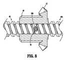
図5および6に最もよく示されるように、親ねじ46は、二重ねじ山62、64を有し、各々が、例えば、ステープル留め機能およびクランプ機能などのエンドエフェクタ20のそれぞれの機能を実行するように構成されている。具体的には、親ねじ46の近位端部分46aは、第1のねじ山ピッチを有するねじ山付き外面62を有し、親ねじ46の遠位端部分46bは、第1のねじ山ピッチとは異なる第2のねじ山ピッチを有するねじ山付き外面64を有する。親ねじ46の近位端部分46aのねじ山付き外面62のねじ山ピッチは、親ねじ46の遠位端部分46bのねじ山付き外面64のねじ山ピッチよりも大きい。態様では、親ねじ46は、近位および遠位端部分46a、46bの間に移行ねじ山を有してもよい。他の態様では、近位および遠位端部分46a、46bの間のねじ山ピッチの変化は、急激であってもよい。 5 and 6,
親ねじ46の近位端部分46aのねじ山付き外面62のねじ山ピッチが比較的大きい(例えば、約2倍)ため、親ねじ46の近位端部分46aは、エンドエフェクタ20のステープル留め機能を実施するのにより好適である。例えば、より大きなねじ山ピッチは、その回転当たりの親ねじ46のより大きな軸方向並進を可能にし、それによって、エンドエフェクタ20のステープル留め機能のより迅速な作動を生み出す。親ねじ46の遠位端部分46bのねじ山付き外面64のねじ山ピッチが小さいため、親ねじ46の遠位端部分46bは、エンドエフェクタ20のクランプ機能を実施するのにより好適である。例えば、より小さなねじ山ピッチは、親ねじ46がその回転当たりより短い距離を並進する結果として、エンドエフェクタ20のジョー部材20a、20bのより細かく制御された開閉を可能にし、ジョー部材20a、20bの間に配置された組織をより制御された速度で圧縮することを可能にする。 Because the thread pitch of the threaded
動作中、エンドエフェクタ20のジョー部材20a、20bの間に組織を受容した状態で、発射スイッチ16を作動して、電池34からモータ36に電力を伝達してもよい。モータ36は、歯車ボックス38の駆動シャフト40を回転させ、これは、第2のカラー50および第1のカラー48の同時回転を駆動する。第1のカラー48のピン56が親ねじ46の遠位端部分46bのねじ山付き外面64に受容されるため、第1のカラー48の回転は、親ねじ46の遠位移動を駆動して、最終的に組織の周りでエンドエフェクタ20のジョー部材20a、20bを閉鎖する。モータ36の継続的な作動は、最終的に、親ねじ46の遠位端部分46bを第1のカラー48との係合から外して前進させ、親ねじ46の近位端部分46aを第1のカラー48内に前進させる。 In operation, with tissue received between
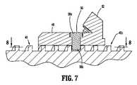
図7および8を参照すると、一実施形態では、ピン56は、第1のカラー48で支持されたヘッド部分56aと、親ねじ46の螺旋溝内に延びるステムまたは本体部分56bと、を含むことが企図される。ピン56の本体部分56bは、親ねじ46のねじ山と接触しそれに沿って摺動するための楕円形の横断面プロファイルを有してもよい。楕円形の横断面プロファイルを有するピン56の本体部分56bが示され、説明されているが、本体部分56bは、例えば、円形、卵形、三角形、三日月形などの、親ねじ46のねじ山に沿って摺動することができる任意の形状の横断面プロファイルを有してもよいことが企図される。ピン56の本体部分56bの楕円形の横断面プロファイルは、親ねじ46の近位端部分46aおよび遠位端部分46bの異なるピッチ間のピン56の移行を容易にする。さらに、ピン56の本体部分56bの楕円形の横断面プロファイルは、ピン56と親ねじ46のねじ山との間で接触する表面積を増加させる。 7 and 8, in one embodiment, the
親ねじ46の近位端部分46aが第1のカラー48と係合した状態で、第1のカラー48の回転は、上記のように、親ねじ46の近位端部分46aのより大きなねじ山ピッチのために、ねじ山46の比較的より速い遠位移動を駆動する。親ねじ46の比較的速い遠位移動は、ステープルをエンドエフェクタ20からジョー部材20a、20bの間にクランプされた組織内に急速に駆動する。さらに、並進可能なナイフを含むエンドエフェクタ20の場合、親ねじ46の遠位移動はまた、組織を通るナイフ(図示せず)の遠位並進をもたらし、それによって組織を切断し得ることが企図される。 With the
電池34が低いか切れている、またはそうでなければ発射スイッチ16の作動が所望の出力をもたらさないシナリオでは、伝達機構42は、手動で動作されてもよい。具体的には、キャップ80は、ハウジング部分26から取り外され、ハンドルアセンブリ12の外管70を露出させてもよい。臨床医は、外管70のアーム76a、76bを把持し、外管70を長手方向軸「X」の周りで回転させてもよい。親ねじ46は外管70にピン留めされているので、外管70の回転は、親ねじ46の回転をもたらし、エンドエフェクタ20を手動で開放するか、エンドエフェクタ20を閉鎖するか、エンドエフェクタ20からステープルを発射するか、または組織を切断する。 In scenarios where the
本明細書に記載の構成要素のいずれも、強度、耐久性、耐摩耗性、重量、耐腐食性、製造の容易さ、製造コストなどを考慮して、金属、プラスチック、樹脂、複合材料などのいずれかから製造され得る。 Any of the components described herein may be made of metals, plastics, resins, composites, etc., for reasons of strength, durability, wear resistance, weight, corrosion resistance, ease of manufacture, cost of manufacture, etc. can be made from any
本開示の手術器具の実施形態に対して様々な変更がなされてもよいことが理解されるであろう。したがって、上の説明は、限定するものではなく、単に実施形態の例証として解釈されるべきである。当業者であれば、本開示の範囲および趣旨内での他の変更を想定するであろう。例えば、1つの記載した実施形態のありとあらゆる特徴が、別の実施形態に好適に組み込まれてもよい。 It will be appreciated that various modifications may be made to the embodiments of the surgical instrument of the present disclosure. Therefore, the above description should not be construed as limiting, but merely as exemplifications of embodiments. Those skilled in the art will envision other modifications within the scope and spirit of this disclosure. For example, any and all features of one described embodiment may suitably be incorporated into another embodiment.
Claims (20)
Translated fromJapaneseハンドルハウジングと、
前記ハンドルハウジング内に配置されたモータと、
前記モータに動作可能に結合され、かつエンドエフェクタの機能を動作させるために前記モータによって並進されるように構成された親ねじであって、前記親ねじが、
第1のピッチを有する近位ねじ山と、
前記近位ねじ山の前記第1のピッチとは異なる、第2のピッチを有する遠位ねじ山と、を含む、親ねじと、を備える、ハンドルアセンブリ。A handle assembly for a handheld surgical instrument comprising:
a handle housing;
a motor disposed within the handle housing;
A lead screw operably coupled to the motor and configured to be translated by the motor to operate a function of an end effector, the lead screw comprising:
a proximal thread having a first pitch;
a distal thread having a second pitch that is different than the first pitch of the proximal thread; and a lead screw.
前記親ねじと平行である長手方向軸を画定する上部ハウジング部分と、
前記上部ハウジング部分から下向きかつ近位に延びる下部ハウジング部分と、を含む、請求項9に記載のハンドルアセンブリ。The handle housing is
an upper housing portion defining a longitudinal axis parallel to the lead screw;
a lower housing portion extending downwardly and proximally from the upper housing portion.
ハンドルハウジングと、
前記ハンドルハウジングによって支持されたモータと、
前記モータに動作可能に結合され、かつ前記モータの作動に応答して近位または遠位のうちの少なくとも1つに移動するように構成された親ねじであって、エンドエフェクタの個別の機能を実行するように構成された二重ねじ山を有する、親ねじと、
前記ハンドルハウジングに結合されたノブハウジングと、
前記ノブハウジングに結合された近位端部分およびエンドエフェクタに結合されるように構成された遠位端部分を有するシャフト部分と、を備える、ハンドルアセンブリ。A handle assembly for a handheld surgical instrument comprising:
a handle housing;
a motor supported by the handle housing;
a lead screw operably coupled to the motor and configured to move at least one of proximally or distally in response to actuation of the motor, the lead screw performing a discrete function of an end effector; a lead screw having a double thread configured to perform
a knob housing coupled to the handle housing;
A handle assembly comprising a shaft portion having a proximal end portion coupled to the knob housing and a distal end portion configured to be coupled to an end effector.
ねじ山付き外面を有する近位端部分と、
ねじ山付き外面を有する遠位端部分と、を含み、前記近位端部分の前記ねじ山付き外面が、前記親ねじの前記遠位端部分の前記ねじ山付き外面とは異なるねじ山ピッチを有する、請求項14に記載のハンドルアセンブリ。The lead screw is
a proximal end portion having a threaded outer surface;
a distal end portion having a threaded outer surface, wherein the threaded outer surface of the proximal end portion has a different thread pitch than the threaded outer surface of the distal end portion of the lead screw. 15. The handle assembly of claim 14, comprising:
第1のカラーの回転が前記親ねじを並進させるように、前記親ねじの周りに配置され、かつ前記親ねじにねじ結合された前記第1のカラーと、
前記モータに結合され、かつ前記第1のカラーのかさ歯車と噛み合い係合するかさ歯車を有する第2のカラーと、を含む、請求項14に記載のハンドルアセンブリ。further comprising a gear assembly operably coupling the motor and the lead screw, the gear assembly comprising:
a first collar disposed about and threadedly coupled to the lead screw such that rotation of the first collar translates the lead screw;
and a second collar coupled to the motor and having bevel gears in meshing engagement with the bevel gears of the first collar.
Applications Claiming Priority (3)
| Application Number | Priority Date | Filing Date | Title |
|---|---|---|---|
| CN201921228479 | 2019-07-31 | ||
| CN201921228479.9 | 2019-07-31 | ||
| PCT/CN2019/103482WO2021017079A1 (en) | 2019-07-31 | 2019-08-30 | Hand-held electromechanical surgical instruments |
Publications (2)
| Publication Number | Publication Date |
|---|---|
| JP2022553596Atrue JP2022553596A (en) | 2022-12-26 |
| JP7417704B2 JP7417704B2 (en) | 2024-01-18 |
Family
ID=73620347
Family Applications (1)
| Application Number | Title | Priority Date | Filing Date |
|---|---|---|---|
| JP2022500884AActiveJP7417704B2 (en) | 2019-07-31 | 2019-08-30 | handheld electromechanical surgical instrument |
Country Status (7)
| Country | Link |
|---|---|
| US (1) | US11839376B2 (en) |
| EP (1) | EP4003186A4 (en) |
| JP (1) | JP7417704B2 (en) |
| CN (2) | CN212089645U (en) |
| AU (1) | AU2019459615A1 (en) |
| CA (1) | CA3143809A1 (en) |
| WO (1) | WO2021017079A1 (en) |
Families Citing this family (183)
| Publication number | Priority date | Publication date | Assignee | Title |
|---|---|---|---|---|
| US20070084897A1 (en) | 2003-05-20 | 2007-04-19 | Shelton Frederick E Iv | Articulating surgical stapling instrument incorporating a two-piece e-beam firing mechanism |
| US9060770B2 (en) | 2003-05-20 | 2015-06-23 | Ethicon Endo-Surgery, Inc. | Robotically-driven surgical instrument with E-beam driver |
| US9072535B2 (en) | 2011-05-27 | 2015-07-07 | Ethicon Endo-Surgery, Inc. | Surgical stapling instruments with rotatable staple deployment arrangements |
| US11998198B2 (en) | 2004-07-28 | 2024-06-04 | Cilag Gmbh International | Surgical stapling instrument incorporating a two-piece E-beam firing mechanism |
| US11890012B2 (en) | 2004-07-28 | 2024-02-06 | Cilag Gmbh International | Staple cartridge comprising cartridge body and attached support |
| US11246590B2 (en) | 2005-08-31 | 2022-02-15 | Cilag Gmbh International | Staple cartridge including staple drivers having different unfired heights |
| US7669746B2 (en) | 2005-08-31 | 2010-03-02 | Ethicon Endo-Surgery, Inc. | Staple cartridges for forming staples having differing formed staple heights |
| US10159482B2 (en) | 2005-08-31 | 2018-12-25 | Ethicon Llc | Fastener cartridge assembly comprising a fixed anvil and different staple heights |
| US11793518B2 (en) | 2006-01-31 | 2023-10-24 | Cilag Gmbh International | Powered surgical instruments with firing system lockout arrangements |
| US8708213B2 (en) | 2006-01-31 | 2014-04-29 | Ethicon Endo-Surgery, Inc. | Surgical instrument having a feedback system |
| US20120292367A1 (en) | 2006-01-31 | 2012-11-22 | Ethicon Endo-Surgery, Inc. | Robotically-controlled end effector |
| US7845537B2 (en) | 2006-01-31 | 2010-12-07 | Ethicon Endo-Surgery, Inc. | Surgical instrument having recording capabilities |
| US8186555B2 (en) | 2006-01-31 | 2012-05-29 | Ethicon Endo-Surgery, Inc. | Motor-driven surgical cutting and fastening instrument with mechanical closure system |
| US8992422B2 (en) | 2006-03-23 | 2015-03-31 | Ethicon Endo-Surgery, Inc. | Robotically-controlled endoscopic accessory channel |
| US10568652B2 (en) | 2006-09-29 | 2020-02-25 | Ethicon Llc | Surgical staples having attached drivers of different heights and stapling instruments for deploying the same |
| US11980366B2 (en) | 2006-10-03 | 2024-05-14 | Cilag Gmbh International | Surgical instrument |
| US8632535B2 (en) | 2007-01-10 | 2014-01-21 | Ethicon Endo-Surgery, Inc. | Interlock and surgical instrument including same |
| US8684253B2 (en) | 2007-01-10 | 2014-04-01 | Ethicon Endo-Surgery, Inc. | Surgical instrument with wireless communication between a control unit of a robotic system and remote sensor |
| US20080169333A1 (en) | 2007-01-11 | 2008-07-17 | Shelton Frederick E | Surgical stapler end effector with tapered distal end |
| US8931682B2 (en) | 2007-06-04 | 2015-01-13 | Ethicon Endo-Surgery, Inc. | Robotically-controlled shaft based rotary drive systems for surgical instruments |
| US11564682B2 (en) | 2007-06-04 | 2023-01-31 | Cilag Gmbh International | Surgical stapler device |
| US11849941B2 (en) | 2007-06-29 | 2023-12-26 | Cilag Gmbh International | Staple cartridge having staple cavities extending at a transverse angle relative to a longitudinal cartridge axis |
| US11986183B2 (en) | 2008-02-14 | 2024-05-21 | Cilag Gmbh International | Surgical cutting and fastening instrument comprising a plurality of sensors to measure an electrical parameter |
| JP5410110B2 (en) | 2008-02-14 | 2014-02-05 | エシコン・エンド−サージェリィ・インコーポレイテッド | Surgical cutting / fixing instrument with RF electrode |
| US8636736B2 (en) | 2008-02-14 | 2014-01-28 | Ethicon Endo-Surgery, Inc. | Motorized surgical cutting and fastening instrument |
| US8573465B2 (en) | 2008-02-14 | 2013-11-05 | Ethicon Endo-Surgery, Inc. | Robotically-controlled surgical end effector system with rotary actuated closure systems |
| US9585657B2 (en) | 2008-02-15 | 2017-03-07 | Ethicon Endo-Surgery, Llc | Actuator for releasing a layer of material from a surgical end effector |
| US8210411B2 (en) | 2008-09-23 | 2012-07-03 | Ethicon Endo-Surgery, Inc. | Motor-driven surgical cutting instrument |
| US9386983B2 (en) | 2008-09-23 | 2016-07-12 | Ethicon Endo-Surgery, Llc | Robotically-controlled motorized surgical instrument |
| US11648005B2 (en) | 2008-09-23 | 2023-05-16 | Cilag Gmbh International | Robotically-controlled motorized surgical instrument with an end effector |
| US9005230B2 (en) | 2008-09-23 | 2015-04-14 | Ethicon Endo-Surgery, Inc. | Motorized surgical instrument |
| US8608045B2 (en) | 2008-10-10 | 2013-12-17 | Ethicon Endo-Sugery, Inc. | Powered surgical cutting and stapling apparatus with manually retractable firing system |
| US8220688B2 (en) | 2009-12-24 | 2012-07-17 | Ethicon Endo-Surgery, Inc. | Motor-driven surgical cutting instrument with electric actuator directional control assembly |
| US12213666B2 (en) | 2010-09-30 | 2025-02-04 | Cilag Gmbh International | Tissue thickness compensator comprising layers |
| US11812965B2 (en) | 2010-09-30 | 2023-11-14 | Cilag Gmbh International | Layer of material for a surgical end effector |
| US9386988B2 (en) | 2010-09-30 | 2016-07-12 | Ethicon End-Surgery, LLC | Retainer assembly including a tissue thickness compensator |
| US10945731B2 (en) | 2010-09-30 | 2021-03-16 | Ethicon Llc | Tissue thickness compensator comprising controlled release and expansion |
| US9788834B2 (en) | 2010-09-30 | 2017-10-17 | Ethicon Llc | Layer comprising deployable attachment members |
| US9629814B2 (en) | 2010-09-30 | 2017-04-25 | Ethicon Endo-Surgery, Llc | Tissue thickness compensator configured to redistribute compressive forces |
| US11925354B2 (en) | 2010-09-30 | 2024-03-12 | Cilag Gmbh International | Staple cartridge comprising staples positioned within a compressible portion thereof |
| AU2012250197B2 (en) | 2011-04-29 | 2017-08-10 | Ethicon Endo-Surgery, Inc. | Staple cartridge comprising staples positioned within a compressible portion thereof |
| US11207064B2 (en) | 2011-05-27 | 2021-12-28 | Cilag Gmbh International | Automated end effector component reloading system for use with a robotic system |
| BR112014024098B1 (en) | 2012-03-28 | 2021-05-25 | Ethicon Endo-Surgery, Inc. | staple cartridge |
| MX358135B (en) | 2012-03-28 | 2018-08-06 | Ethicon Endo Surgery Inc | Tissue thickness compensator comprising a plurality of layers. |
| US9101358B2 (en) | 2012-06-15 | 2015-08-11 | Ethicon Endo-Surgery, Inc. | Articulatable surgical instrument comprising a firing drive |
| US12383267B2 (en) | 2012-06-28 | 2025-08-12 | Cilag Gmbh International | Robotically powered surgical device with manually-actuatable reversing system |
| US20140001231A1 (en) | 2012-06-28 | 2014-01-02 | Ethicon Endo-Surgery, Inc. | Firing system lockout arrangements for surgical instruments |
| US9289256B2 (en) | 2012-06-28 | 2016-03-22 | Ethicon Endo-Surgery, Llc | Surgical end effectors having angled tissue-contacting surfaces |
| BR112015021082B1 (en) | 2013-03-01 | 2022-05-10 | Ethicon Endo-Surgery, Inc | surgical instrument |
| RU2672520C2 (en) | 2013-03-01 | 2018-11-15 | Этикон Эндо-Серджери, Инк. | Hingedly turnable surgical instruments with conducting ways for signal transfer |
| US9629629B2 (en) | 2013-03-14 | 2017-04-25 | Ethicon Endo-Surgey, LLC | Control systems for surgical instruments |
| BR112015026109B1 (en) | 2013-04-16 | 2022-02-22 | Ethicon Endo-Surgery, Inc | surgical instrument |
| US9775609B2 (en) | 2013-08-23 | 2017-10-03 | Ethicon Llc | Tamper proof circuit for surgical instrument battery pack |
| US10013049B2 (en) | 2014-03-26 | 2018-07-03 | Ethicon Llc | Power management through sleep options of segmented circuit and wake up control |
| US12232723B2 (en) | 2014-03-26 | 2025-02-25 | Cilag Gmbh International | Systems and methods for controlling a segmented circuit |
| US20150272580A1 (en) | 2014-03-26 | 2015-10-01 | Ethicon Endo-Surgery, Inc. | Verification of number of battery exchanges/procedure count |
| CN106456176B (en) | 2014-04-16 | 2019-06-28 | 伊西康内外科有限责任公司 | Fastener Cartridge Including Extensions With Different Configurations |
| US10327764B2 (en) | 2014-09-26 | 2019-06-25 | Ethicon Llc | Method for creating a flexible staple line |
| BR112016023825B1 (en) | 2014-04-16 | 2022-08-02 | Ethicon Endo-Surgery, Llc | STAPLE CARTRIDGE FOR USE WITH A SURGICAL STAPLER AND STAPLE CARTRIDGE FOR USE WITH A SURGICAL INSTRUMENT |
| US20150297225A1 (en) | 2014-04-16 | 2015-10-22 | Ethicon Endo-Surgery, Inc. | Fastener cartridges including extensions having different configurations |
| CN106456159B (en) | 2014-04-16 | 2019-03-08 | 伊西康内外科有限责任公司 | Fastener Cartridge Assembly and Nail Retainer Cover Arrangement |
| US10135242B2 (en) | 2014-09-05 | 2018-11-20 | Ethicon Llc | Smart cartridge wake up operation and data retention |
| US11311294B2 (en) | 2014-09-05 | 2022-04-26 | Cilag Gmbh International | Powered medical device including measurement of closure state of jaws |
| BR112017004361B1 (en) | 2014-09-05 | 2023-04-11 | Ethicon Llc | ELECTRONIC SYSTEM FOR A SURGICAL INSTRUMENT |
| US10105142B2 (en) | 2014-09-18 | 2018-10-23 | Ethicon Llc | Surgical stapler with plurality of cutting elements |
| US11523821B2 (en) | 2014-09-26 | 2022-12-13 | Cilag Gmbh International | Method for creating a flexible staple line |
| US9924944B2 (en) | 2014-10-16 | 2018-03-27 | Ethicon Llc | Staple cartridge comprising an adjunct material |
| US10517594B2 (en) | 2014-10-29 | 2019-12-31 | Ethicon Llc | Cartridge assemblies for surgical staplers |
| US10736636B2 (en) | 2014-12-10 | 2020-08-11 | Ethicon Llc | Articulatable surgical instrument system |
| US10085748B2 (en) | 2014-12-18 | 2018-10-02 | Ethicon Llc | Locking arrangements for detachable shaft assemblies with articulatable surgical end effectors |
| US9987000B2 (en) | 2014-12-18 | 2018-06-05 | Ethicon Llc | Surgical instrument assembly comprising a flexible articulation system |
| MX389118B (en) | 2014-12-18 | 2025-03-20 | Ethicon Llc | SURGICAL INSTRUMENT WITH AN ANVIL THAT CAN BE SELECTIVELY MOVED ON A DISCRETE, NON-MOBILE AXIS RELATIVE TO A STAPLE CARTRIDGE. |
| US11154301B2 (en) | 2015-02-27 | 2021-10-26 | Cilag Gmbh International | Modular stapling assembly |
| US10441279B2 (en) | 2015-03-06 | 2019-10-15 | Ethicon Llc | Multiple level thresholds to modify operation of powered surgical instruments |
| US10433844B2 (en) | 2015-03-31 | 2019-10-08 | Ethicon Llc | Surgical instrument with selectively disengageable threaded drive systems |
| US10105139B2 (en) | 2015-09-23 | 2018-10-23 | Ethicon Llc | Surgical stapler having downstream current-based motor control |
| US10299878B2 (en) | 2015-09-25 | 2019-05-28 | Ethicon Llc | Implantable adjunct systems for determining adjunct skew |
| US11890015B2 (en) | 2015-09-30 | 2024-02-06 | Cilag Gmbh International | Compressible adjunct with crossing spacer fibers |
| US10433846B2 (en) | 2015-09-30 | 2019-10-08 | Ethicon Llc | Compressible adjunct with crossing spacer fibers |
| US10478188B2 (en) | 2015-09-30 | 2019-11-19 | Ethicon Llc | Implantable layer comprising a constricted configuration |
| US10292704B2 (en) | 2015-12-30 | 2019-05-21 | Ethicon Llc | Mechanisms for compensating for battery pack failure in powered surgical instruments |
| US10265068B2 (en) | 2015-12-30 | 2019-04-23 | Ethicon Llc | Surgical instruments with separable motors and motor control circuits |
| US11213293B2 (en) | 2016-02-09 | 2022-01-04 | Cilag Gmbh International | Articulatable surgical instruments with single articulation link arrangements |
| US10448948B2 (en) | 2016-02-12 | 2019-10-22 | Ethicon Llc | Mechanisms for compensating for drivetrain failure in powered surgical instruments |
| US10357247B2 (en) | 2016-04-15 | 2019-07-23 | Ethicon Llc | Surgical instrument with multiple program responses during a firing motion |
| US10828028B2 (en) | 2016-04-15 | 2020-11-10 | Ethicon Llc | Surgical instrument with multiple program responses during a firing motion |
| US20170296173A1 (en) | 2016-04-18 | 2017-10-19 | Ethicon Endo-Surgery, Llc | Method for operating a surgical instrument |
| US10500000B2 (en) | 2016-08-16 | 2019-12-10 | Ethicon Llc | Surgical tool with manual control of end effector jaws |
| US11090048B2 (en) | 2016-12-21 | 2021-08-17 | Cilag Gmbh International | Method for resetting a fuse of a surgical instrument shaft |
| US10813638B2 (en) | 2016-12-21 | 2020-10-27 | Ethicon Llc | Surgical end effectors with expandable tissue stop arrangements |
| US10973516B2 (en) | 2016-12-21 | 2021-04-13 | Ethicon Llc | Surgical end effectors and adaptable firing members therefor |
| JP7010956B2 (en) | 2016-12-21 | 2022-01-26 | エシコン エルエルシー | How to staple tissue |
| JP7010957B2 (en) | 2016-12-21 | 2022-01-26 | エシコン エルエルシー | Shaft assembly with lockout |
| US20180168625A1 (en) | 2016-12-21 | 2018-06-21 | Ethicon Endo-Surgery, Llc | Surgical stapling instruments with smart staple cartridges |
| US10881399B2 (en) | 2017-06-20 | 2021-01-05 | Ethicon Llc | Techniques for adaptive control of motor velocity of a surgical stapling and cutting instrument |
| US10307170B2 (en) | 2017-06-20 | 2019-06-04 | Ethicon Llc | Method for closed loop control of motor velocity of a surgical stapling and cutting instrument |
| US10779820B2 (en) | 2017-06-20 | 2020-09-22 | Ethicon Llc | Systems and methods for controlling motor speed according to user input for a surgical instrument |
| EP3420947B1 (en) | 2017-06-28 | 2022-05-25 | Cilag GmbH International | Surgical instrument comprising selectively actuatable rotatable couplers |
| US11484310B2 (en) | 2017-06-28 | 2022-11-01 | Cilag Gmbh International | Surgical instrument comprising a shaft including a closure tube profile |
| USD906355S1 (en) | 2017-06-28 | 2020-12-29 | Ethicon Llc | Display screen or portion thereof with a graphical user interface for a surgical instrument |
| US10932772B2 (en) | 2017-06-29 | 2021-03-02 | Ethicon Llc | Methods for closed loop velocity control for robotic surgical instrument |
| US11974742B2 (en) | 2017-08-03 | 2024-05-07 | Cilag Gmbh International | Surgical system comprising an articulation bailout |
| US11944300B2 (en) | 2017-08-03 | 2024-04-02 | Cilag Gmbh International | Method for operating a surgical system bailout |
| US11134944B2 (en) | 2017-10-30 | 2021-10-05 | Cilag Gmbh International | Surgical stapler knife motion controls |
| US10842490B2 (en) | 2017-10-31 | 2020-11-24 | Ethicon Llc | Cartridge body design with force reduction based on firing completion |
| US10779826B2 (en) | 2017-12-15 | 2020-09-22 | Ethicon Llc | Methods of operating surgical end effectors |
| US10835330B2 (en) | 2017-12-19 | 2020-11-17 | Ethicon Llc | Method for determining the position of a rotatable jaw of a surgical instrument attachment assembly |
| US11179151B2 (en) | 2017-12-21 | 2021-11-23 | Cilag Gmbh International | Surgical instrument comprising a display |
| US12336705B2 (en) | 2017-12-21 | 2025-06-24 | Cilag Gmbh International | Continuous use self-propelled stapling instrument |
| US11207065B2 (en) | 2018-08-20 | 2021-12-28 | Cilag Gmbh International | Method for fabricating surgical stapler anvils |
| US11291440B2 (en) | 2018-08-20 | 2022-04-05 | Cilag Gmbh International | Method for operating a powered articulatable surgical instrument |
| US20200054321A1 (en) | 2018-08-20 | 2020-02-20 | Ethicon Llc | Surgical instruments with progressive jaw closure arrangements |
| US11696761B2 (en) | 2019-03-25 | 2023-07-11 | Cilag Gmbh International | Firing drive arrangements for surgical systems |
| US11903581B2 (en) | 2019-04-30 | 2024-02-20 | Cilag Gmbh International | Methods for stapling tissue using a surgical instrument |
| US20200345359A1 (en) | 2019-04-30 | 2020-11-05 | Ethicon Llc | Tissue stop for a surgical instrument |
| US11684434B2 (en) | 2019-06-28 | 2023-06-27 | Cilag Gmbh International | Surgical RFID assemblies for instrument operational setting control |
| US11241235B2 (en) | 2019-06-28 | 2022-02-08 | Cilag Gmbh International | Method of using multiple RFID chips with a surgical assembly |
| US11771419B2 (en) | 2019-06-28 | 2023-10-03 | Cilag Gmbh International | Packaging for a replaceable component of a surgical stapling system |
| US12004740B2 (en) | 2019-06-28 | 2024-06-11 | Cilag Gmbh International | Surgical stapling system having an information decryption protocol |
| US11660163B2 (en) | 2019-06-28 | 2023-05-30 | Cilag Gmbh International | Surgical system with RFID tags for updating motor assembly parameters |
| US12035913B2 (en) | 2019-12-19 | 2024-07-16 | Cilag Gmbh International | Staple cartridge comprising a deployable knife |
| US11701111B2 (en) | 2019-12-19 | 2023-07-18 | Cilag Gmbh International | Method for operating a surgical stapling instrument |
| US11844520B2 (en) | 2019-12-19 | 2023-12-19 | Cilag Gmbh International | Staple cartridge comprising driver retention members |
| US11871925B2 (en) | 2020-07-28 | 2024-01-16 | Cilag Gmbh International | Surgical instruments with dual spherical articulation joint arrangements |
| US11931025B2 (en) | 2020-10-29 | 2024-03-19 | Cilag Gmbh International | Surgical instrument comprising a releasable closure drive lock |
| USD1013170S1 (en) | 2020-10-29 | 2024-01-30 | Cilag Gmbh International | Surgical instrument assembly |
| US11779330B2 (en) | 2020-10-29 | 2023-10-10 | Cilag Gmbh International | Surgical instrument comprising a jaw alignment system |
| US11896217B2 (en) | 2020-10-29 | 2024-02-13 | Cilag Gmbh International | Surgical instrument comprising an articulation lock |
| US11844518B2 (en) | 2020-10-29 | 2023-12-19 | Cilag Gmbh International | Method for operating a surgical instrument |
| US12053175B2 (en) | 2020-10-29 | 2024-08-06 | Cilag Gmbh International | Surgical instrument comprising a stowed closure actuator stop |
| US11627960B2 (en) | 2020-12-02 | 2023-04-18 | Cilag Gmbh International | Powered surgical instruments with smart reload with separately attachable exteriorly mounted wiring connections |
| US11653920B2 (en) | 2020-12-02 | 2023-05-23 | Cilag Gmbh International | Powered surgical instruments with communication interfaces through sterile barrier |
| US11737751B2 (en) | 2020-12-02 | 2023-08-29 | Cilag Gmbh International | Devices and methods of managing energy dissipated within sterile barriers of surgical instrument housings |
| US11944296B2 (en) | 2020-12-02 | 2024-04-02 | Cilag Gmbh International | Powered surgical instruments with external connectors |
| US11653915B2 (en) | 2020-12-02 | 2023-05-23 | Cilag Gmbh International | Surgical instruments with sled location detection and adjustment features |
| US11890010B2 (en) | 2020-12-02 | 2024-02-06 | Cllag GmbH International | Dual-sided reinforced reload for surgical instruments |
| US11744581B2 (en) | 2020-12-02 | 2023-09-05 | Cilag Gmbh International | Powered surgical instruments with multi-phase tissue treatment |
| US11849943B2 (en) | 2020-12-02 | 2023-12-26 | Cilag Gmbh International | Surgical instrument with cartridge release mechanisms |
| WO2022160247A1 (en)* | 2021-01-29 | 2022-08-04 | Covidien Lp | Multi-function ergonomic handheld surgical instrument and system |
| US11812964B2 (en) | 2021-02-26 | 2023-11-14 | Cilag Gmbh International | Staple cartridge comprising a power management circuit |
| US12324580B2 (en) | 2021-02-26 | 2025-06-10 | Cilag Gmbh International | Method of powering and communicating with a staple cartridge |
| US11696757B2 (en) | 2021-02-26 | 2023-07-11 | Cilag Gmbh International | Monitoring of internal systems to detect and track cartridge motion status |
| US11701113B2 (en) | 2021-02-26 | 2023-07-18 | Cilag Gmbh International | Stapling instrument comprising a separate power antenna and a data transfer antenna |
| US11730473B2 (en) | 2021-02-26 | 2023-08-22 | Cilag Gmbh International | Monitoring of manufacturing life-cycle |
| US11925349B2 (en) | 2021-02-26 | 2024-03-12 | Cilag Gmbh International | Adjustment to transfer parameters to improve available power |
| US11751869B2 (en) | 2021-02-26 | 2023-09-12 | Cilag Gmbh International | Monitoring of multiple sensors over time to detect moving characteristics of tissue |
| US11980362B2 (en) | 2021-02-26 | 2024-05-14 | Cilag Gmbh International | Surgical instrument system comprising a power transfer coil |
| US11723657B2 (en) | 2021-02-26 | 2023-08-15 | Cilag Gmbh International | Adjustable communication based on available bandwidth and power capacity |
| US11950777B2 (en) | 2021-02-26 | 2024-04-09 | Cilag Gmbh International | Staple cartridge comprising an information access control system |
| US11749877B2 (en) | 2021-02-26 | 2023-09-05 | Cilag Gmbh International | Stapling instrument comprising a signal antenna |
| US11793514B2 (en) | 2021-02-26 | 2023-10-24 | Cilag Gmbh International | Staple cartridge comprising sensor array which may be embedded in cartridge body |
| US11744583B2 (en) | 2021-02-26 | 2023-09-05 | Cilag Gmbh International | Distal communication array to tune frequency of RF systems |
| US12108951B2 (en) | 2021-02-26 | 2024-10-08 | Cilag Gmbh International | Staple cartridge comprising a sensing array and a temperature control system |
| US11717291B2 (en) | 2021-03-22 | 2023-08-08 | Cilag Gmbh International | Staple cartridge comprising staples configured to apply different tissue compression |
| US11806011B2 (en) | 2021-03-22 | 2023-11-07 | Cilag Gmbh International | Stapling instrument comprising tissue compression systems |
| US11723658B2 (en) | 2021-03-22 | 2023-08-15 | Cilag Gmbh International | Staple cartridge comprising a firing lockout |
| US11737749B2 (en) | 2021-03-22 | 2023-08-29 | Cilag Gmbh International | Surgical stapling instrument comprising a retraction system |
| US11826042B2 (en)* | 2021-03-22 | 2023-11-28 | Cilag Gmbh International | Surgical instrument comprising a firing drive including a selectable leverage mechanism |
| US11826012B2 (en) | 2021-03-22 | 2023-11-28 | Cilag Gmbh International | Stapling instrument comprising a pulsed motor-driven firing rack |
| US11759202B2 (en) | 2021-03-22 | 2023-09-19 | Cilag Gmbh International | Staple cartridge comprising an implantable layer |
| US12102323B2 (en) | 2021-03-24 | 2024-10-01 | Cilag Gmbh International | Rotary-driven surgical stapling assembly comprising a floatable component |
| US11849944B2 (en) | 2021-03-24 | 2023-12-26 | Cilag Gmbh International | Drivers for fastener cartridge assemblies having rotary drive screws |
| US11832816B2 (en) | 2021-03-24 | 2023-12-05 | Cilag Gmbh International | Surgical stapling assembly comprising nonplanar staples and planar staples |
| US11744603B2 (en) | 2021-03-24 | 2023-09-05 | Cilag Gmbh International | Multi-axis pivot joints for surgical instruments and methods for manufacturing same |
| US11896218B2 (en) | 2021-03-24 | 2024-02-13 | Cilag Gmbh International | Method of using a powered stapling device |
| US11786243B2 (en) | 2021-03-24 | 2023-10-17 | Cilag Gmbh International | Firing members having flexible portions for adapting to a load during a surgical firing stroke |
| US11903582B2 (en) | 2021-03-24 | 2024-02-20 | Cilag Gmbh International | Leveraging surfaces for cartridge installation |
| US11849945B2 (en) | 2021-03-24 | 2023-12-26 | Cilag Gmbh International | Rotary-driven surgical stapling assembly comprising eccentrically driven firing member |
| US11857183B2 (en) | 2021-03-24 | 2024-01-02 | Cilag Gmbh International | Stapling assembly components having metal substrates and plastic bodies |
| US11786239B2 (en) | 2021-03-24 | 2023-10-17 | Cilag Gmbh International | Surgical instrument articulation joint arrangements comprising multiple moving linkage features |
| US11896219B2 (en) | 2021-03-24 | 2024-02-13 | Cilag Gmbh International | Mating features between drivers and underside of a cartridge deck |
| US11793516B2 (en) | 2021-03-24 | 2023-10-24 | Cilag Gmbh International | Surgical staple cartridge comprising longitudinal support beam |
| US11701119B2 (en)* | 2021-05-26 | 2023-07-18 | Covidien Lp | Powered stapling device with rack release |
| US11826047B2 (en) | 2021-05-28 | 2023-11-28 | Cilag Gmbh International | Stapling instrument comprising jaw mounts |
| US11980363B2 (en) | 2021-10-18 | 2024-05-14 | Cilag Gmbh International | Row-to-row staple array variations |
| CN116019518B (en)* | 2021-10-27 | 2025-10-03 | 苏州英途康医疗科技有限公司 | Buttons for medical device handles and staplers |
| US12089841B2 (en) | 2021-10-28 | 2024-09-17 | Cilag CmbH International | Staple cartridge identification systems |
| US11937816B2 (en) | 2021-10-28 | 2024-03-26 | Cilag Gmbh International | Electrical lead arrangements for surgical instruments |
| US12432790B2 (en) | 2021-10-28 | 2025-09-30 | Cilag Gmbh International | Method and device for transmitting UART communications over a security short range wireless communication |
| CN116269804B (en)* | 2021-12-06 | 2025-10-03 | 深圳市精锋医疗科技股份有限公司 | Surgical instruments and surgical robots |
| CN118678925A (en)* | 2022-02-10 | 2024-09-20 | 柯惠有限合伙公司 | Surgical device with three-position safety trigger assembly |
| CN115227337B (en)* | 2022-08-01 | 2024-01-12 | 上海腾复医疗科技有限公司 | Vascular opening device |
| CN118986445B (en)* | 2024-10-23 | 2025-02-25 | 江苏科曼医疗科技有限公司 | A surgical instrument |
Citations (7)
| Publication number | Priority date | Publication date | Assignee | Title |
|---|---|---|---|---|
| JP2009506799A (en)* | 2005-06-03 | 2009-02-19 | タイコ ヘルスケア グループ リミテッド パートナーシップ | Power-driven surgical instrument |
| JP2009538684A (en)* | 2006-06-02 | 2009-11-12 | タイコ ヘルスケア グループ リミテッド パートナーシップ | Surgical stapler with timer and feedback display |
| JP2010540192A (en)* | 2007-10-04 | 2010-12-24 | エシコン エンド−サージェリー,インク. | Electric self-driven surgical instrument with manual release |
| JP2011189136A (en)* | 2010-03-16 | 2011-09-29 | Tyco Healthcare Group Lp | Method and apparatus for determining parameter of linear motion in surgical instrument |
| US20170135747A1 (en)* | 2015-11-13 | 2017-05-18 | Ethicon Endo-Surgery, Llc | Dual Step Bailout for Motorized RF Device |
| JP2018512053A (en)* | 2015-02-27 | 2018-05-10 | エシコン エルエルシーEthicon LLC | Modular stapling assembly |
| JP2018519072A (en)* | 2015-06-26 | 2018-07-19 | エシコン エルエルシーEthicon LLC | Surgical stapler emergency detachment assembly |
Family Cites Families (23)
| Publication number | Priority date | Publication date | Assignee | Title |
|---|---|---|---|---|
| US5443198A (en)* | 1991-10-18 | 1995-08-22 | United States Surgical Corporation | Surgical fastener applying apparatus |
| US5433721A (en)* | 1992-01-17 | 1995-07-18 | Ethicon, Inc. | Endoscopic instrument having a torsionally stiff drive shaft for applying fasteners to tissue |
| CA2148667A1 (en)* | 1994-05-05 | 1995-11-06 | Carlo A. Mililli | Self-contained powered surgical apparatus |
| US5628446A (en)* | 1994-05-05 | 1997-05-13 | United States Surgical Corporation | Self-contained powered surgical apparatus |
| US7464847B2 (en)* | 2005-06-03 | 2008-12-16 | Tyco Healthcare Group Lp | Surgical stapler with timer and feedback display |
| US7615044B2 (en)* | 2006-05-03 | 2009-11-10 | Greatbatch Ltd. | Deflectable sheath handle assembly and method therefor |
| US8931682B2 (en)* | 2007-06-04 | 2015-01-13 | Ethicon Endo-Surgery, Inc. | Robotically-controlled shaft based rotary drive systems for surgical instruments |
| CN102793571B (en)* | 2007-09-21 | 2014-12-17 | 柯惠Lp公司 | Surgical device |
| US8517241B2 (en) | 2010-04-16 | 2013-08-27 | Covidien Lp | Hand-held surgical devices |
| US8752749B2 (en)* | 2008-02-14 | 2014-06-17 | Ethicon Endo-Surgery, Inc. | Robotically-controlled disposable motor-driven loading unit |
| US20140005640A1 (en)* | 2012-06-28 | 2014-01-02 | Ethicon Endo-Surgery, Inc. | Surgical end effector jaw and electrode configurations |
| MX377739B (en)* | 2013-04-16 | 2025-03-11 | Ethicon Endo Surgery Inc | SURGICAL INSTRUMENT COMPRISING A CLOSING DRIVE MECHANISM AND A FIRING DRIVE MECHANISM OPERATED FROM THE SAME ROTATING OUTLET. |
| US9826976B2 (en)* | 2013-04-16 | 2017-11-28 | Ethicon Llc | Motor driven surgical instruments with lockable dual drive shafts |
| US9629633B2 (en) | 2013-07-09 | 2017-04-25 | Covidien Lp | Surgical device, surgical adapters for use between surgical handle assembly and surgical loading units, and methods of use |
| US10226253B2 (en) | 2015-06-26 | 2019-03-12 | Ethicon Llc | Firing assembly for circular stapler |
| CN205307032U (en)* | 2015-12-21 | 2016-06-15 | 北京派尔特医疗科技股份有限公司 | Anastomat self -lock device |
| CN109219405B (en)* | 2016-04-01 | 2022-05-24 | 伊西康有限责任公司 | Surgical Suture System |
| US10420552B2 (en)* | 2016-04-01 | 2019-09-24 | Ethicon Llc | Surgical stapling system configured to provide selective cutting of tissue |
| US10743850B2 (en) | 2016-04-04 | 2020-08-18 | Ethicon Llc | Surgical instrument with locking articulation drive wheel |
| CN109963516B (en)* | 2016-04-18 | 2021-10-29 | 伊西康有限责任公司 | Surgical instrument including primary and secondary firing latches |
| US11160538B2 (en)* | 2016-10-31 | 2021-11-02 | Devicor Medical Products, Inc. | Biopsy device with linear actuator |
| US10881451B2 (en)* | 2017-04-27 | 2021-01-05 | Ethicon Llc | Lead screw assembly for articulation control in surgical instrument |
| CN111466974B (en)* | 2019-01-24 | 2021-05-14 | 苏州英途康医疗科技有限公司 | Surgical instrument and linear stapler |
- 2019
- 2019-08-30CNCN201921428899.1Upatent/CN212089645U/enactiveActive
- 2019-08-30USUS17/628,696patent/US11839376B2/enactiveActive
- 2019-08-30WOPCT/CN2019/103482patent/WO2021017079A1/ennot_activeCeased
- 2019-08-30CNCN201980098983.8Apatent/CN114173682A/enactivePending
- 2019-08-30CACA3143809Apatent/CA3143809A1/enactivePending
- 2019-08-30AUAU2019459615Apatent/AU2019459615A1/ennot_activeAbandoned
- 2019-08-30EPEP19939085.7Apatent/EP4003186A4/enactivePending
- 2019-08-30JPJP2022500884Apatent/JP7417704B2/enactiveActive
Patent Citations (7)
| Publication number | Priority date | Publication date | Assignee | Title |
|---|---|---|---|---|
| JP2009506799A (en)* | 2005-06-03 | 2009-02-19 | タイコ ヘルスケア グループ リミテッド パートナーシップ | Power-driven surgical instrument |
| JP2009538684A (en)* | 2006-06-02 | 2009-11-12 | タイコ ヘルスケア グループ リミテッド パートナーシップ | Surgical stapler with timer and feedback display |
| JP2010540192A (en)* | 2007-10-04 | 2010-12-24 | エシコン エンド−サージェリー,インク. | Electric self-driven surgical instrument with manual release |
| JP2011189136A (en)* | 2010-03-16 | 2011-09-29 | Tyco Healthcare Group Lp | Method and apparatus for determining parameter of linear motion in surgical instrument |
| JP2018512053A (en)* | 2015-02-27 | 2018-05-10 | エシコン エルエルシーEthicon LLC | Modular stapling assembly |
| JP2018519072A (en)* | 2015-06-26 | 2018-07-19 | エシコン エルエルシーEthicon LLC | Surgical stapler emergency detachment assembly |
| US20170135747A1 (en)* | 2015-11-13 | 2017-05-18 | Ethicon Endo-Surgery, Llc | Dual Step Bailout for Motorized RF Device |
Also Published As
| Publication number | Publication date |
|---|---|
| CA3143809A1 (en) | 2021-02-04 |
| CN212089645U (en) | 2020-12-08 |
| JP7417704B2 (en) | 2024-01-18 |
| CN114173682A (en) | 2022-03-11 |
| US11839376B2 (en) | 2023-12-12 |
| WO2021017079A1 (en) | 2021-02-04 |
| US20220265272A1 (en) | 2022-08-25 |
| EP4003186A1 (en) | 2022-06-01 |
| AU2019459615A1 (en) | 2022-03-10 |
| EP4003186A4 (en) | 2023-11-22 |
Similar Documents
| Publication | Publication Date | Title |
|---|---|---|
| JP7417704B2 (en) | handheld electromechanical surgical instrument | |
| US10806528B2 (en) | Surgical adapter assemblies for use between surgical handle assembly and surgical end effectors | |
| US10485549B2 (en) | Surgical device, surgical adapters for use between surgical handle assembly and surgical loading units, and methods of use | |
| US7431188B1 (en) | Surgical stapling apparatus with powered articulation | |
| JP5646910B2 (en) | A safe way for electric surgical instruments | |
| CN104918564A (en) | Circular stapler with selectable motorized and manual control, including a control ring | |
| JP2010505519A5 (en) | ||
| WO2007016288A2 (en) | A surgical device | |
| CN111227891B (en) | Electric surgical instrument handheld assembly and electric surgical instrument | |
| CN209564169U (en) | Single motor electrical surgical instrument | |
| US11504117B2 (en) | Hand-held surgical instruments | |
| CN111227890B (en) | Electric surgical instrument handheld assembly and electric surgical instrument |
Legal Events
| Date | Code | Title | Description |
|---|---|---|---|
| A621 | Written request for application examination | Free format text:JAPANESE INTERMEDIATE CODE: A621 Effective date:20220829 | |
| A977 | Report on retrieval | Free format text:JAPANESE INTERMEDIATE CODE: A971007 Effective date:20230630 | |
| A131 | Notification of reasons for refusal | Free format text:JAPANESE INTERMEDIATE CODE: A131 Effective date:20230704 | |
| A521 | Request for written amendment filed | Free format text:JAPANESE INTERMEDIATE CODE: A523 Effective date:20230921 | |
| TRDD | Decision of grant or rejection written | ||
| A01 | Written decision to grant a patent or to grant a registration (utility model) | Free format text:JAPANESE INTERMEDIATE CODE: A01 Effective date:20231213 | |
| A61 | First payment of annual fees (during grant procedure) | Free format text:JAPANESE INTERMEDIATE CODE: A61 Effective date:20240105 | |
| R150 | Certificate of patent or registration of utility model | Ref document number:7417704 Country of ref document:JP Free format text:JAPANESE INTERMEDIATE CODE: R150 |