JP2022551111A - A Hybrid Spectroscopically and Coherently Coupled Fiber Laser Amplifier System Including a Coherent Optical Monolithic Phased Array with Small Tiles - Google Patents
A Hybrid Spectroscopically and Coherently Coupled Fiber Laser Amplifier System Including a Coherent Optical Monolithic Phased Array with Small TilesDownload PDFInfo
- Publication number
- JP2022551111A JP2022551111AJP2022520699AJP2022520699AJP2022551111AJP 2022551111 AJP2022551111 AJP 2022551111AJP 2022520699 AJP2022520699 AJP 2022520699AJP 2022520699 AJP2022520699 AJP 2022520699AJP 2022551111 AJP2022551111 AJP 2022551111A
- Authority
- JP
- Japan
- Prior art keywords
- array
- beams
- seed
- cells
- input
- Prior art date
- Legal status (The legal status is an assumption and is not a legal conclusion. Google has not performed a legal analysis and makes no representation as to the accuracy of the status listed.)
- Granted
Links
Images


Classifications
- G—PHYSICS
- G02—OPTICS
- G02B—OPTICAL ELEMENTS, SYSTEMS OR APPARATUS
- G02B27/00—Optical systems or apparatus not provided for by any of the groups G02B1/00 - G02B26/00, G02B30/00
- G02B27/10—Beam splitting or combining systems
- G02B27/1006—Beam splitting or combining systems for splitting or combining different wavelengths
- H—ELECTRICITY
- H01—ELECTRIC ELEMENTS
- H01S—DEVICES USING THE PROCESS OF LIGHT AMPLIFICATION BY STIMULATED EMISSION OF RADIATION [LASER] TO AMPLIFY OR GENERATE LIGHT; DEVICES USING STIMULATED EMISSION OF ELECTROMAGNETIC RADIATION IN WAVE RANGES OTHER THAN OPTICAL
- H01S3/00—Lasers, i.e. devices using stimulated emission of electromagnetic radiation in the infrared, visible or ultraviolet wave range
- H01S3/005—Optical devices external to the laser cavity, specially adapted for lasers, e.g. for homogenisation of the beam or for manipulating laser pulses, e.g. pulse shaping
- G—PHYSICS
- G02—OPTICS
- G02B—OPTICAL ELEMENTS, SYSTEMS OR APPARATUS
- G02B27/00—Optical systems or apparatus not provided for by any of the groups G02B1/00 - G02B26/00, G02B30/00
- G02B27/09—Beam shaping, e.g. changing the cross-sectional area, not otherwise provided for
- G02B27/0927—Systems for changing the beam intensity distribution, e.g. Gaussian to top-hat
- G—PHYSICS
- G02—OPTICS
- G02B—OPTICAL ELEMENTS, SYSTEMS OR APPARATUS
- G02B27/00—Optical systems or apparatus not provided for by any of the groups G02B1/00 - G02B26/00, G02B30/00
- G02B27/09—Beam shaping, e.g. changing the cross-sectional area, not otherwise provided for
- G02B27/0938—Using specific optical elements
- G02B27/0944—Diffractive optical elements, e.g. gratings, holograms
- H—ELECTRICITY
- H01—ELECTRIC ELEMENTS
- H01S—DEVICES USING THE PROCESS OF LIGHT AMPLIFICATION BY STIMULATED EMISSION OF RADIATION [LASER] TO AMPLIFY OR GENERATE LIGHT; DEVICES USING STIMULATED EMISSION OF ELECTROMAGNETIC RADIATION IN WAVE RANGES OTHER THAN OPTICAL
- H01S3/00—Lasers, i.e. devices using stimulated emission of electromagnetic radiation in the infrared, visible or ultraviolet wave range
- H01S3/05—Construction or shape of optical resonators; Accommodation of active medium therein; Shape of active medium
- H01S3/06—Construction or shape of active medium
- H01S3/063—Waveguide lasers, i.e. whereby the dimensions of the waveguide are of the order of the light wavelength
- H01S3/067—Fibre lasers
- H01S3/06754—Fibre amplifiers
- H—ELECTRICITY
- H01—ELECTRIC ELEMENTS
- H01S—DEVICES USING THE PROCESS OF LIGHT AMPLIFICATION BY STIMULATED EMISSION OF RADIATION [LASER] TO AMPLIFY OR GENERATE LIGHT; DEVICES USING STIMULATED EMISSION OF ELECTROMAGNETIC RADIATION IN WAVE RANGES OTHER THAN OPTICAL
- H01S3/00—Lasers, i.e. devices using stimulated emission of electromagnetic radiation in the infrared, visible or ultraviolet wave range
- H01S3/10—Controlling the intensity, frequency, phase, polarisation or direction of the emitted radiation, e.g. switching, gating, modulating or demodulating
- H01S3/10007—Controlling the intensity, frequency, phase, polarisation or direction of the emitted radiation, e.g. switching, gating, modulating or demodulating in optical amplifiers
- H01S3/10023—Controlling the intensity, frequency, phase, polarisation or direction of the emitted radiation, e.g. switching, gating, modulating or demodulating in optical amplifiers by functional association of additional optical elements, e.g. filters, gratings, reflectors
- H01S3/1003—Controlling the intensity, frequency, phase, polarisation or direction of the emitted radiation, e.g. switching, gating, modulating or demodulating in optical amplifiers by functional association of additional optical elements, e.g. filters, gratings, reflectors tunable optical elements, e.g. acousto-optic filters, tunable gratings
- H—ELECTRICITY
- H01—ELECTRIC ELEMENTS
- H01S—DEVICES USING THE PROCESS OF LIGHT AMPLIFICATION BY STIMULATED EMISSION OF RADIATION [LASER] TO AMPLIFY OR GENERATE LIGHT; DEVICES USING STIMULATED EMISSION OF ELECTROMAGNETIC RADIATION IN WAVE RANGES OTHER THAN OPTICAL
- H01S3/00—Lasers, i.e. devices using stimulated emission of electromagnetic radiation in the infrared, visible or ultraviolet wave range
- H01S3/10—Controlling the intensity, frequency, phase, polarisation or direction of the emitted radiation, e.g. switching, gating, modulating or demodulating
- H01S3/10053—Phase control
- H—ELECTRICITY
- H01—ELECTRIC ELEMENTS
- H01S—DEVICES USING THE PROCESS OF LIGHT AMPLIFICATION BY STIMULATED EMISSION OF RADIATION [LASER] TO AMPLIFY OR GENERATE LIGHT; DEVICES USING STIMULATED EMISSION OF ELECTROMAGNETIC RADIATION IN WAVE RANGES OTHER THAN OPTICAL
- H01S3/00—Lasers, i.e. devices using stimulated emission of electromagnetic radiation in the infrared, visible or ultraviolet wave range
- H01S3/10—Controlling the intensity, frequency, phase, polarisation or direction of the emitted radiation, e.g. switching, gating, modulating or demodulating
- H01S3/13—Stabilisation of laser output parameters, e.g. frequency or amplitude
- H01S3/1301—Stabilisation of laser output parameters, e.g. frequency or amplitude in optical amplifiers
- H—ELECTRICITY
- H01—ELECTRIC ELEMENTS
- H01S—DEVICES USING THE PROCESS OF LIGHT AMPLIFICATION BY STIMULATED EMISSION OF RADIATION [LASER] TO AMPLIFY OR GENERATE LIGHT; DEVICES USING STIMULATED EMISSION OF ELECTROMAGNETIC RADIATION IN WAVE RANGES OTHER THAN OPTICAL
- H01S3/00—Lasers, i.e. devices using stimulated emission of electromagnetic radiation in the infrared, visible or ultraviolet wave range
- H01S3/10—Controlling the intensity, frequency, phase, polarisation or direction of the emitted radiation, e.g. switching, gating, modulating or demodulating
- H01S3/13—Stabilisation of laser output parameters, e.g. frequency or amplitude
- H01S3/1307—Stabilisation of the phase
- H—ELECTRICITY
- H01—ELECTRIC ELEMENTS
- H01S—DEVICES USING THE PROCESS OF LIGHT AMPLIFICATION BY STIMULATED EMISSION OF RADIATION [LASER] TO AMPLIFY OR GENERATE LIGHT; DEVICES USING STIMULATED EMISSION OF ELECTROMAGNETIC RADIATION IN WAVE RANGES OTHER THAN OPTICAL
- H01S3/00—Lasers, i.e. devices using stimulated emission of electromagnetic radiation in the infrared, visible or ultraviolet wave range
- H01S3/23—Arrangements of two or more lasers not provided for in groups H01S3/02 - H01S3/22, e.g. tandem arrangements of separate active media
- H01S3/2383—Parallel arrangements
- H01S3/2391—Parallel arrangements emitting at different wavelengths
- H—ELECTRICITY
- H01—ELECTRIC ELEMENTS
- H01S—DEVICES USING THE PROCESS OF LIGHT AMPLIFICATION BY STIMULATED EMISSION OF RADIATION [LASER] TO AMPLIFY OR GENERATE LIGHT; DEVICES USING STIMULATED EMISSION OF ELECTROMAGNETIC RADIATION IN WAVE RANGES OTHER THAN OPTICAL
- H01S3/00—Lasers, i.e. devices using stimulated emission of electromagnetic radiation in the infrared, visible or ultraviolet wave range
- H01S3/30—Lasers, i.e. devices using stimulated emission of electromagnetic radiation in the infrared, visible or ultraviolet wave range using scattering effects, e.g. stimulated Brillouin or Raman effects
- H01S3/302—Lasers, i.e. devices using stimulated emission of electromagnetic radiation in the infrared, visible or ultraviolet wave range using scattering effects, e.g. stimulated Brillouin or Raman effects in an optical fibre
- H—ELECTRICITY
- H01—ELECTRIC ELEMENTS
- H01S—DEVICES USING THE PROCESS OF LIGHT AMPLIFICATION BY STIMULATED EMISSION OF RADIATION [LASER] TO AMPLIFY OR GENERATE LIGHT; DEVICES USING STIMULATED EMISSION OF ELECTROMAGNETIC RADIATION IN WAVE RANGES OTHER THAN OPTICAL
- H01S2301/00—Functional characteristics
- H01S2301/03—Suppression of nonlinear conversion, e.g. specific design to suppress for example stimulated brillouin scattering [SBS], mainly in optical fibres in combination with multimode pumping
- H—ELECTRICITY
- H01—ELECTRIC ELEMENTS
- H01S—DEVICES USING THE PROCESS OF LIGHT AMPLIFICATION BY STIMULATED EMISSION OF RADIATION [LASER] TO AMPLIFY OR GENERATE LIGHT; DEVICES USING STIMULATED EMISSION OF ELECTROMAGNETIC RADIATION IN WAVE RANGES OTHER THAN OPTICAL
- H01S2301/00—Functional characteristics
- H01S2301/20—Lasers with a special output beam profile or cross-section, e.g. non-Gaussian
- H01S2301/206—Top hat profile
- H—ELECTRICITY
- H01—ELECTRIC ELEMENTS
- H01S—DEVICES USING THE PROCESS OF LIGHT AMPLIFICATION BY STIMULATED EMISSION OF RADIATION [LASER] TO AMPLIFY OR GENERATE LIGHT; DEVICES USING STIMULATED EMISSION OF ELECTROMAGNETIC RADIATION IN WAVE RANGES OTHER THAN OPTICAL
- H01S3/00—Lasers, i.e. devices using stimulated emission of electromagnetic radiation in the infrared, visible or ultraviolet wave range
- H01S3/005—Optical devices external to the laser cavity, specially adapted for lasers, e.g. for homogenisation of the beam or for manipulating laser pulses, e.g. pulse shaping
- H01S3/0085—Modulating the output, i.e. the laser beam is modulated outside the laser cavity
- H—ELECTRICITY
- H01—ELECTRIC ELEMENTS
- H01S—DEVICES USING THE PROCESS OF LIGHT AMPLIFICATION BY STIMULATED EMISSION OF RADIATION [LASER] TO AMPLIFY OR GENERATE LIGHT; DEVICES USING STIMULATED EMISSION OF ELECTROMAGNETIC RADIATION IN WAVE RANGES OTHER THAN OPTICAL
- H01S3/00—Lasers, i.e. devices using stimulated emission of electromagnetic radiation in the infrared, visible or ultraviolet wave range
- H01S3/10—Controlling the intensity, frequency, phase, polarisation or direction of the emitted radiation, e.g. switching, gating, modulating or demodulating
- H01S3/13—Stabilisation of laser output parameters, e.g. frequency or amplitude
- H01S3/1304—Stabilisation of laser output parameters, e.g. frequency or amplitude by using an active reference, e.g. second laser, klystron or other standard frequency source
- H—ELECTRICITY
- H01—ELECTRIC ELEMENTS
- H01S—DEVICES USING THE PROCESS OF LIGHT AMPLIFICATION BY STIMULATED EMISSION OF RADIATION [LASER] TO AMPLIFY OR GENERATE LIGHT; DEVICES USING STIMULATED EMISSION OF ELECTROMAGNETIC RADIATION IN WAVE RANGES OTHER THAN OPTICAL
- H01S3/00—Lasers, i.e. devices using stimulated emission of electromagnetic radiation in the infrared, visible or ultraviolet wave range
- H01S3/10—Controlling the intensity, frequency, phase, polarisation or direction of the emitted radiation, e.g. switching, gating, modulating or demodulating
- H01S3/13—Stabilisation of laser output parameters, e.g. frequency or amplitude
- H01S3/1305—Feedback control systems
- H—ELECTRICITY
- H01—ELECTRIC ELEMENTS
- H01S—DEVICES USING THE PROCESS OF LIGHT AMPLIFICATION BY STIMULATED EMISSION OF RADIATION [LASER] TO AMPLIFY OR GENERATE LIGHT; DEVICES USING STIMULATED EMISSION OF ELECTROMAGNETIC RADIATION IN WAVE RANGES OTHER THAN OPTICAL
- H01S3/00—Lasers, i.e. devices using stimulated emission of electromagnetic radiation in the infrared, visible or ultraviolet wave range
- H01S3/14—Lasers, i.e. devices using stimulated emission of electromagnetic radiation in the infrared, visible or ultraviolet wave range characterised by the material used as the active medium
- H01S3/16—Solid materials
- H01S3/1601—Solid materials characterised by an active (lasing) ion
- H01S3/1603—Solid materials characterised by an active (lasing) ion rare earth
- H01S3/1618—Solid materials characterised by an active (lasing) ion rare earth ytterbium
Landscapes
- Physics & Mathematics (AREA)
- Electromagnetism (AREA)
- Optics & Photonics (AREA)
- Engineering & Computer Science (AREA)
- Plasma & Fusion (AREA)
- General Physics & Mathematics (AREA)
- Lasers (AREA)
- Optical Modulation, Optical Deflection, Nonlinear Optics, Optical Demodulation, Optical Logic Elements (AREA)
- Optical Couplings Of Light Guides (AREA)
Abstract
Translated fromJapanese
Description
Translated fromJapanese[0001]本開示は、概して、ハイブリッドの分光的およびコヒーレントに結合されたファイバレーザ増幅器システム、より詳細には、離間したビーム整形器アレイを有するビーム整形器アレイアセンブリを含むハイブリッドの分光的およびコヒーレントに結合されたファイバレーザ増幅器システムに関し、ビーム整形器アレイのうちの1つは、各々が円形ガウスまたは他の低フィルファクタビームを高フィルファクタビームへ変換する、密充填されたタイル状のビーム整形器セルを含み、他のビーム整形器アレイもまた、クリッピングに起因する損失パワーを最小限にしながら、各々が高フィルファクタビームのうちの1つの拡大を停止する、密充填されたタイル状のビーム整形器セルを含む。 [0001] This disclosure relates generally to a hybrid spectroscopic and coherently coupled fiber laser amplifier system, and more particularly to a hybrid spectroscopic and coherent fiber laser amplifier system including a beam shaper array assembly having spaced apart beam shaper arrays. one of the beam shaper arrays, each of which transforms a circular Gaussian or other low fill factor beam into a high fill factor beam, with closely packed tiles of beam shaping , and other beamformer arrays, each stopping expansion of one of the high fill-factor beams while minimizing power loss due to clipping. Contains shaper cells.
[0002]高パワーレーザ増幅器は、工業、商業、軍用などを含む多くの用途を有する。レーザ増幅器の設計者は、これらの用途および他の用途のためにレーザ増幅器のパワーを増大させる方法を継続して調査している。レーザ増幅器の1つの知られているタイプは、シードビームとシードビームを増幅するポンプビームとを受信するドープファイバを採用し、高パワーレーザビームを生成するファイバレーザ増幅器であり、ファイバは、約10~20μm以上の活性コア直径を有する。ファイバレーザ増幅器は、それらの高い効率、高いパワー拡張性、および優れたビーム品質が理由で、指向性エネルギー兵器のエネルギー源として有用である。 [0002] High power laser amplifiers have many applications, including industrial, commercial, military, and the like. Laser amplifier designers continue to search for ways to increase the power of laser amplifiers for these and other applications. One known type of laser amplifier is a fiber laser amplifier that employs a doped fiber to receive a seed beam and a pump beam that amplifies the seed beam to produce a high power laser beam, where the fiber is about 10 It has an active core diameter of ~20 μm or greater. Fiber laser amplifiers are useful as energy sources for directed energy weapons because of their high efficiency, high power scalability, and excellent beam quality.
[0003]ファイバレーザ増幅器設計における改善は、その実用パワーおよびビーム品質限界に近づくためにファイバ増幅器の出力パワーを増大させている。出力パワーをさらに増大させるため、いくつかのファイバレーザシステムは、より高いパワーを生成するために何らかの方式で増幅ビームを結合する複数のファイバレーザ増幅器を採用する。このタイプのファイバレーザ増幅器システム、特に、高エネルギービームをターゲットに向ける指向性エネルギー兵器に採用されるものの設計課題は、ビームがビーム直径にわたって均一相を有する単一ビーム出力を提供し、その結果として、ビームが小焦点に集束され得るように、複数のファイバ増幅器からのビームを結合することである。長距離(遠方場)における小さい点に結合ビームを集束させることが、ビームの品質を画定する。 [0003] Improvements in fiber laser amplifier design have increased the output power of fiber amplifiers to approach their practical power and beam quality limits. To further increase the output power, some fiber laser systems employ multiple fiber laser amplifiers that combine the amplified beams in some fashion to produce higher power. A design challenge of this type of fiber laser amplifier system, particularly those employed in directed energy weapons that aim high-energy beams at targets, is to provide a single beam output in which the beam has uniform phase across the beam diameter, resulting in , is to combine the beams from multiple fiber amplifiers so that the beams can be focused to a small focus. Focusing the combined beam to a small point at long range (far field) defines the quality of the beam.
[0004]ビームコンバイナレーザ兵器システムをより高いパワーへとスケーリングするのには2つの手法が存在する。1つの手法は、スペクトルビーム結合(SBC)として知られており、この場合、異なる波長の複数のレーザが、回折格子または他の分散光学素子上で単一ビームへと結合される。他方の手法は、コヒーレントビーム結合(CBC)として知られており、この場合、複数の相互にコヒーレントなレーザが、互いと位相ロックされ、ビームスプリッタを使用して近接場内で重複すること、または合成ビーム、俗に「フェーズドアレイ」と称される構成、を形成するために並んでタイリングすること、のいずれかによって、単一ビームへと結合される。 [0004] There are two approaches to scaling beam combiner laser weapon systems to higher powers. One approach is known as spectral beam combining (SBC), where multiple lasers of different wavelengths are combined into a single beam over a diffraction grating or other dispersive optical element. The other approach is known as coherent beam combining (CBC), where multiple mutually coherent lasers are phase-locked with each other and overlapped or combined in the near-field using beam splitters. The beams are combined into a single beam, either by tiling them side by side to form a configuration commonly referred to as a "phased array."
[0005]異なるビーム結合手法のうち、フェーズドアレイ手法は、良好なビーム品質を有する単により高いパワーを超えた追加の有用性を提供するという点で唯一無二である。並んだレーザタイル間の相対位相(「ピストン」)を変えることにより、タイル状ビームにわたる複合波面が合成され得る。この合成された波面は、アレイ素子にわたって線形位相ランプを適用することによって高速ビーム操作を提供し得るか、またはより一般的には、複合タイル状ビームに共役波面を押し付けることによって任意の下流波面収差を補償し得るか、のいずれかである。これは、高プラットフォームジッタにもかかわらず、高速移動するターゲットに対する照準点維持を可能にし得、また大きな介在大気乱流および空中光学収差にもかかわらず、遠隔ターゲットに対する近回折限界点の形成を可能にし得る。この点に関して、能力は、本質的に、従来の可変鏡(DM)を使用したビーム制御システムのものと同様であるが、DMハードウェアの必要性はなく、桁違いに高速の作動能力を伴う。DMは、典型的には、鏡面を物理的に変形させる必要性に起因して、それらの作動速度が音響クラス(multi-kHz)の速度に制限される一方、フェーズドアレイピストンは、商業的にファイバ結合された導波電気光学変調器を使用してGHzクラスの速度で作動され得る。これらの高速度は、迅速に変化する波面障害、特に、移動する空気プラットフォームに対する空中光学効果から生じるもの、の能動的補償のために望ましい場合がある。 [0005] Of the different beam combining techniques, the phased array technique is unique in that it offers additional utility beyond simply higher power with good beam quality. By varying the relative phase ("piston") between the side-by-side laser tiles, a compound wavefront across the tiled beam can be synthesized. This synthesized wavefront can provide fast beam steering by applying a linear phase ramp across the array elements or, more generally, any downstream wavefront aberrations by forcing a conjugate wavefront onto the composite tiled beam. can be compensated for; This may enable point-of-sight maintenance on fast-moving targets despite high platform jitter, and the formation of near-diffraction-limited points on remote targets despite large intervening atmospheric turbulence and airborne optical aberrations. can be In this regard, the capabilities are essentially similar to those of conventional beam control systems using deformable mirrors (DM), but without the need for DM hardware, with order-of-magnitude faster actuation capability. . DMs are typically limited in their actuation speed to acoustic-class (multi-kHz) speeds due to the need to physically deform the mirror surface, while phased array pistons are commercially available It can be operated at GHz-class speeds using fiber-coupled guided electro-optic modulators. These high velocities may be desirable for active compensation of rapidly changing wavefront disturbances, particularly those resulting from airborne optical effects on moving air platforms.
[0006]これらのタイプのファイバアレイ増幅器においては、フラットトップビームの場合、高パワービームによって占有される結合ビームエリアの一部と規定される、高い空間フィルファクタを有するファイバビームのアレイを提供することが望ましい。非フラットトッププロファイルを有するビームの場合、フィルファクタは、より一般的には、1-σp2/(4P2)と規定され得、式中、Pは、平均レーザ強度であり、σp2は、結合ビームエリアにわたるレーザ強度の分散である。これらのシステム内のファイバビームエミッタは、典型的には円形の近ガウスプロファイルを有するビームを放出するが、他の非ガウスプロファイルが可能であり、ビームは、互いに隣り合ってアレイ内に配置される。次いで、ファイバビームは、コリメーティング光学素子によってコリメートされ、ビーム間の空間が、遠方場においてはオフターゲットである可能性が高い空間サイドローブ内に光パワーを発生させる。したがって、遠方場において可能な限り小さい点を獲得するためにフィルファクタを増加させることによって、ターゲットに結合ビームを投影する望遠鏡の開口全体を充填することが望ましい。知られているファイバ増幅器システムは、典型的には、フィルファクタを増加させるために円形ガウスビームをコリメートするレンズを採用する。しかしながら、その素子が近ガウスプロファイルを有する高フィルファクタビームアレイは、ビームのウイングが近隣素子によってブロックされるため、高いクリッピング損失を呈する。故に、単レンズおよび近ガウスビームを使用して可能であるものより高いフィルファクタおよびより低いクリッピング損失を有するビーム整形器アレイが必要とされる。[0006] These types of fiber array amplifiers provide an array of fiber beams with a high spatial fill factor, defined as the portion of the combined beam area occupied by the high power beam for flat top beams. is desirable. For beams with non-flat top profiles, the fill factor can be more generally defined as 1−σp2 /(4P2 ), where P is the average laser intensity and σp2 is is the distribution of laser intensity over the combined beam area; The fiber beam emitters in these systems typically emit beams with circular near-Gaussian profiles, although other non-Gaussian profiles are possible, and the beams are arranged in arrays next to each other. . The fiber beams are then collimated by collimating optics, and the spaces between the beams generate optical power in spatial sidelobes that are likely off-target in the far field. Therefore, it is desirable to fill the entire aperture of the telescope that projects the combined beam onto the target by increasing the fill factor to obtain the smallest possible point in the far field. Known fiber amplifier systems typically employ lenses that collimate circular Gaussian beams to increase the fill factor. However, high fill factor beam arrays whose elements have near-Gaussian profiles exhibit high clipping losses because the wings of the beam are blocked by neighboring elements. Therefore, there is a need for beam shaper arrays with higher fill factors and lower clipping losses than is possible using single lenses and near-Gaussian beams.
[0039]離間したタイル状のビーム整形器アレイを含むビーム整形器アレイアセンブリを含むハイブリッドの分光的およびコヒーレントに結合されたファイバレーザ増幅器システムを対象とした本開示の実施形態の以下の議論は、本質的に例示にすぎず、本開示またはその応用もしくは使用を限定することはいかようにも意図されない。 [0039] The following discussion of embodiments of the present disclosure directed to a hybrid spectroscopically and coherently coupled fiber laser amplifier system including a beam shaper array assembly including a spaced apart tiled beam shaper array: It is merely exemplary in nature and is not intended to limit the disclosure or its application or uses in any way.
[0040]図1は、ファイバ14上に中心波長λを有する連続波周波数変調シードビームを生成するシードビーム源12を含むCBCファイバレーザ増幅器システム10の概略ブロック図である。源12は、単一縦モード分散フィードバック(DFB)ダイオードレーザ発振器などの主発振器(MO)、および電気光学変調器(EOM)などの周波数変調器を含み得る。EOMは、変調されたシードビームが、下流の高パワーファイバ増幅器内の誘導ブリルアン散乱を抑える実質的に広がった線幅を有するように、ホワイトノイズまたは擬似乱数ビットシーケンス(PRBS)などの周波数変調広がりを提供するRF源(図示せず)からの増幅無線周波数(RF)電気駆動信号によって提供される印加電圧を受信し得る。ファイバ14上の変調されたシードビームは、同じ波長λを有するファイバ18上の複数のスプリットシードビームを作成するために、光スプリッタ16によって分割され、各スプリットシードビームは、位相ロック目的のためにシードビームのサーボ位相制御を提供する別個のEOM20へ送られる。 [0040] FIG. 1 is a schematic block diagram of a CBC fiber
[0041]ファイバ22上の変調されたシードビームの各々は、Ybドープファイバ増幅器などのファイバ増幅器24へ送られ、増幅器24は、典型的には、光ポンプビーム(図示せず)を受信するファイバ22のドープ増幅部分である。増幅ビームのすべては、ファイバ26上へ向けられ、システムエミッタとして動作する、以下に詳細に論じられるビーム整形器アレイアセンブリ40に送られる。ビーム整形器アレイアセンブリ40からの放出された増幅ビームは、結合ビーム内の別個のビームの各々のサンプル部分をサンプリングする位相感知アセンブリ38内のビームスプリッタ28を通って、結合増幅ビームとして向けられる。光スプリッタ16はまた、参照ビーム58を生成するように構成され、この参照ビーム58は、参照ビーム58を変調する参照ビーム変調器178へ送られる。参照ビーム変調器178は、例えば、参照ビーム58の中心周波数をシフトする音響光学変調器、または参照ビーム58にデジタル位相シフトを付与するEOMを含み得る。変調された参照ビーム58は、平坦波面を提供し、またビームスプリッタ28上の結合増幅ビームと重複するように、ビーム拡大器78によって拡大される。重複した参照およびサンプルビームの強度は、光検出器32のアレイ30によって検出される。結合増幅ビームの主部分は、出力ビーム54をターゲット(図示せず)へ向けるビームディレクタ望遠鏡34へ送られる。 [0041] Each of the modulated seed beams on
[0042]光検出器32からの電気信号は、例えば、当業者によく知られている光ヘテロダイン検出(OHD)などの位相ロック技術を使用して、シードビームの位相を補正するようにEOM20を制御するために位相ロック制御器36によって使用される。しかしながら、周波数シフトされた参照ビームを必要としない場合があるか、または代わりに、ビームアレイ全体を単一の検出器に集束させる遠方場生成レンズを使用する他の位相ロック技術(図示せず)が採用され得、この場合、各チャネルのための誤差信号が、当業者によく知られている、例えば、確率的並列勾配下降(SPGD)アルゴリズムなどの様々なマルチディザー手法を使用して電気的に抽出される。制御器36は、波面収差データまたはビーム操作設定点などの位相設定点を決定するために、ボックス58によって提供される他のデータおよび情報を受信し得る。より詳細には、制御器36は、サンプリングされたビーム間の位相差の誤差信号を受信し、それらの誤差信号をEOM20に提供して、シードビームのすべてが位相をロックされるように個々のシードビームの位相を制御する。言い換えると、EOM20は、結合増幅ビームの「ピストン」位相がビーム波面にわたって空間的に均一であるようにシードビーム位相制御を提供する。これはまた、シードビームの位相が電子ビーム操作目的で互いに対して変更されることを可能にする。制御器36はまた、測定された大気異常を補正するためにビームの位相制御を付与することができ、出力ビーム54は、大気収差を通じて伝搬した結果として補正される波面収差を有し得、その結果として、ビーム54が、それがターゲットに衝突するときに所望の品質のものである。 [0042] The electrical signal from
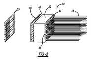
[0043]図2は、ファイバレーザ増幅器システム10から分離されたビーム整形器アレイアセンブリ40の等角図である。論じられるように、アレイアセンブリ40は、100%近くのフィルファクタに、均一のまたは調整された位相または位相面を伴う望遠鏡34の放出開口にわたって均一のまたは調整されたビーム強度を提供する。位相は、上に説明されるような収差のビーム操作または補償のために調整され得る。アレイアセンブリ40は、光学ガラスのモノリシックブロック、またはモノリシックブロックのグループである光エンドキャップ42を含み、ファイバ26の端部が、表面46内に機械加工される好適なステム44によってエンドキャップ42の入力表面46に光学的に溶接され、結果として、増幅ビームは、最小の反射を伴ってエンドキャップ42内へ放出され、マイクロメートル級の精度で正確に離間される。アレイアセンブリ40はまた、一対の離間したタイル状のビーム整形器アレイ48および50を含み、ビーム整形器アレイ48および50の各々は、ビームが所望の様式で整形されるようにビームの空間位相分布または波面を変化させるビーム整形器を各ビームにつき1つ有する密充填されたタイル状のセルのアレイを含む。 [0043] FIG. 2 is an isometric view of the beam
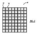
[0044]図3は、ビームが本明細書に論じられる様式で集束されるように整形される表面を伴うビーム整形器52を各々が有する正方形タイル状の副開口ビーム整形器セル56のアレイを示すビーム整形器アレイ48の前面図であり、ビーム整形器アレイ48からビーム整形器アレイ50への伝搬後、ビームは、円形ガウスプロファイルから、セル56のサイズを有する正方形フラットトッププロファイルへ変更される。言い換えると、ビーム整形器アレイ48は、ビームが伝搬する際にビームが平坦になり、ビーム間の空間を光で充填するように、ビームの位相を変化させる。ビーム整形器アレイ50は、ビーム整形器アレイ48と同じ構成のセルおよびビーム整形器を含むが、ビーム整形器は、ビームを拡大する代わりに、それらが、ビームがさらに伝搬する際にビームをフラットトッププロファイルに維持するためにビームの位相面を変化させるように、異なって整形される。この非限定的な実施形態において、セル56のうちの1つによって提供される副開口サイズは、2×2mm2である。[0044] Figure 3 shows an array of square tiled sub-aperture
[0045]述べられたように、ビーム整形器アレイ48は、円形ガウス状の増幅ビームの形状を正方形フラットトップビームへと変化させるように動作し、正方形フラットトップビームは、所望される100%近くのフィルファクタを提供するためにビーム間に最小空隙が存在するように、ある特定の既定の伝搬距離にわたって互いに非常に密接して位置付けられ、すなわち、タイル状にされ、密充填される。言い換えると、ファイバ26からのガウス状のビームは、エンドキャップ42によって二次元アレイ内に互いに隣り合って位置付けられ、次いでガウスピーク間の低い強度エリアは、ビームのアレイにわたるビーム強度がビーム間の最小重複および最小空隙を伴って一定であるように、ビーム整形器アレイ48からビーム整形器アレイ50への伝搬時にビーム整形器アレイ48によって充填される。ビーム整形器アレイ50は、ビーム整形器アレイ48から既定の距離に位置付けられ、ビーム整形器アレイ50からの出力ビームが平坦な位相面を有するようにビームの形状変化を停止するように動作する。 [0045] As mentioned, the
[0046]図4A~図4Fは、増幅ビームのうちの1つについてのビームプロファイルであり、どのようにしてビームプロファイルが、円形ガウスプロファイルから正方形フラットトッププロファイルへ進むために、ビーム整形器アレイ48からビーム整形器アレイ50へ伝搬する際に展開および拡大するかを示す。具体的には、図4Aは、ビーム整形器アレイ48の出力におけるビームのプロファイルを、ガウスプロファイルを有するものとして示し、図4Bは、アレイ48から10mmにおけるビームのプロファイルを示し、図4Cは、アレイ48から20mmにおけるビームのプロファイルを示し、図4Dは、アレイ48から30mmにおけるビームのプロファイルを示し、図4Eは、アレイ48から30mmにおけるビームのプロファイルを示し、図4Fは、ビーム整形器アレイ50の場所でアレイ48から50mmにおけるビームのプロファイルを示す。ビーム整形器アレイ50は、次いで、残留位相およびビームの発散を除去するために、広がったビームをコンジュゲートまたはコリメートして、正方形平坦波面ビームを提供する。連続的な副開口内にビームの重複が存在しないか、最小の重複が存在することから、電子ビーム操作は、様々なビームの位相を変化させることによって利用可能である。言い換えると、別個のビームフットプリントが、ファイバレーザ増幅器システム10の完全適応の光学素子能力を保護する。 [0046] Figures 4A-4F are beam profiles for one of the amplified beams and how the
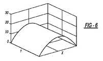
[0047]ビーム整形器52は、アレイ48からアレイ50への伝搬時にビームプロファイルを平坦にし、また正方形にするために必要な形状を獲得するために、ビームのZ伝搬方向に対してX方向およびY方向の両方に整形される。ビーム整形器52の1つの好適な形状は、図5に示され、この形状は、1つの表面に形成される。この実施形態において、ビーム整形器52の基板材料は、溶融シリカであり、XおよびY軸は各々2mmに及び、Z軸は、表面起伏をマイクロメートルで示す。代替的に、別個の表面が、ビーム整形器の形状のXおよびY方向について整形され得る。例えば、図6は、X方向についての好適な形状を示し、図7は、Y方向についての好適な形状を示す。別個のXおよびY方向形状は、同じビーム整形器アレイの対向する側に形成され得るか、または2つの隣接するビーム整形器アレイの片側にあり得る。分けられたXおよびY方向形状を用いたこれらの実施形態は、ビーム整形器アレイ48および50の最大表面起伏を低減し、故にそれらを高い正確性で製造するのをより簡単にすることから、組み合わされたXおよびY方向形状と比較して有利である。 [0047] The
[0048]この非限定的な実施形態において、ビーム整形器アレイ48は、エンドキャップ42の出力表面から離間して示される。しかしながら、ビーム整形器アレイ48は、エンドキャップ42の出力表面に光学的に取り付けられ得るか、またはエンドキャップ42の出力表面上に直接整形され得る。何らかのビーム拡大を可能にするために入力表面46に溶接されるファイバ26の先端とビーム整形器アレイ48との間にいくらかの効果的な自由空間距離を提供することが必要である。図1に示されるように、この効果的な自由空間は、ガラス媒体内の伝搬から、媒体の屈折率を適切に考慮して、部分的または全体的になり得る。ファイバ先端とビーム整形器アレイ48との間の効果的な自由空間の量は、ファイバ26間の副開口ピッチ(間隔)、各ファイバ26から放出されるガウスビームの、開口数、すなわち発散、および望遠鏡34の開口に依存し、目標は、目に見えるわずかなピッチであるが、クリッピング損失なしに副開口内に完全に含まれるように、ビーム整形器アレイ48におけるビームフットプリントサイズを獲得することである。故に、0.03ラジアンの開口数、すなわち半角発散を有する典型的な大モードエリアファイバの場合、および2mmのピッチの場合、ファイバ先端とビーム整形器アレイ48との間の効果的な自由空間距離は、約10mmとなる。 [0048] In this non-limiting embodiment, the
[0049]一対のビーム整形器アレイ48および50は、理論上、説明されるような所望のビーム整形を提供することができるものとするが、実際には、アセンブリ40の製造公差によって引き起こされる、ビーム整形器アレイ50の出力におけるビーム強度プロファイルに様々な波面収差および誤差が存在する可能性が高く、そしてアセンブリ40の製造公差は、アレイ48および50ならびにエンドキャップ42の製造公差と、構成要素の特定の組立セットについて測定されることができる、それらの相対的整列とによって部分的に決定され得る。 [0049] While a pair of
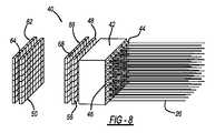
[0050]図8は、ファイバレーザ増幅器システム10から分離されたビーム整形器アレイアセンブリ40の等角図であり、収差の逆を提供するために測定値に基づいて波面補正を提供するように整形されるトリムビーム整形器素子64のアレイを含むトリムビーム整形器アレイ62が、ビーム整形器アレイ50に隣接して提供される。アレイ62内のトリムビーム整形器アレイ素子64の各々は、測定された誤差に基づいて他とは異なり得る。アセンブリ40はまた、ビーム整形器アレイ48からビーム整形器アレイ50へのビームの伝搬後、ビーム整形器アレイ50の出力において測定される強度分布におけるいかなる不均一性も補正されるように、整形されるトリムビーム整形器素子68のアレイを含む、ビーム整形器アレイ48に隣接して提供されるトリムビーム整形器アレイ66を含む。アレイ66内の素子68の各々は、測定された誤差に基づいて他とは異なり得る。代替的に、または加えて、個々の構成要素、例えば、アレイ48および50、またはファイバ26、コネクタ44、およびエンドキャップ42を備える組み立てられたファイバエンドキャップアレイなど、の波面収差が、別個に測定され得、トリムビーム整形器アレイ62および66はまた、それぞれアレイ48および50に隣接して提供され得る。 [0050] FIG. 8 is an isometric view of a beam
[0051]上で論じた実施形態において、ビーム整形器アレイ48および50は、離散素子である。代替の実施形態において、2つのビーム整形器アレイが、単一の光学ブロックの対向面に提供され得、この単一の光学ブロックは、ビームがブロックを通って伝搬する際に低フィルファクタビームがフラットトップ高フィルファクタビームに変換されるように必要な厚さを有する。この実施形態は、光学ブロック72、ブロック72の入力表面に光学的に取り付けられるか、またはそこに直接整形される入力ビーム整形器アレイ74、およびブロック72の出力表面に光学的に取り付けられるか、またはそこに直接整形される出力ビーム整形器アレイ76を含むビーム整形器アレイアセンブリ70の側面図を示す図9に例示され、ビーム整形器アレイ74は、入力表面46に溶接されるファイバ26の先端とビーム整形器アレイ74との間の効果的な自由空間距離を提供するために、エンドキャップ42から離間されるか、またはこれに取り付けられる。同様に、ビーム整形器アレイ48は、エンドキャップ42の表面上に直接整形され得る。これらの実施形態は、高パワービームが通過する表面の数を低減し、故に、望ましくない散乱または後方反射からの光パワー損失を低減することから、有利である。 [0051] In the embodiments discussed above, the
[0052]上の実施形態において、ビーム整形器アレイ48および50は、正方形である。他の実施形態において、個々のビーム整形器およびビームの正方形タイリングは維持するが、結合ビームの外形を望遠鏡34の開口の形状により密接に適合させることが望ましい場合がある。図10は、アレイ48および50として使用され得、ビーム整形器を含むいくつかの正方形ビーム整形器セル82を有するビーム整形器アレイ80の前面図であり、セル82は、ビーム整形器アレイ80の外縁86が円形開口により密接に適合するようにタイリングされる。さらに、本明細書に説明されるタイプの特定のファイバ増幅器システムにおいて、望遠鏡34の主開口は、副鏡を受け入れるためなど、中心オブスキュレーションを有し得る。この問題を解決するため、ビーム整形器アレイ80は、ビームが伝搬しない中心開口部88を有し、これにより、さもなければオブスキュレーションに衝突するビームパワーを無駄にしないようにする。 [0052] In the above embodiment, the
[0053]セル56のすべてが同じ正方形状を有することが上で提案されているが、他の設計においては、中心など、異なるエリア内の結合ビームのパワーまたは強度を制御することが望ましい場合があり、この場合、ビームパワーを相応に調節するために、一部のセルが正方形であり他のセルが長方形であるなど、外側セルは内側セルとは異なる形状を有し得る。この実施形態は、アレイ48および50として使用され得、ビーム整形器94を有するいくつかの正方形内側ビーム整形器セル92およびビーム整形器98を有するいくつかの長方形外側ビーム整形器セル96を有するビーム整形器アレイ90の前面図を示す図11に例示される。 [0053] Although it is suggested above that all of the
[0054]また、セル56は、すべて同じサイズである必要はなく、異なるサイズのセルは、図10に示されるものなど、外周または内周形状をより良好に受け入れ得る。この実施形態は、アレイ48および50として使用され得、1つのサイズのビーム整形器104を有するいくつかの正方形ビーム整形器セル102および別のサイズのビーム整形器108を有するいくつかの正方形ビーム整形器セル106を有するビーム整形器アレイ100の前面図を示す図12に例示される。 [0054] Also, the
[0055]セル56のすべてが直線アレイ内に配置されることも上に提案されているが、他の設計では非直線状のアレイ内にセルを配置することが望ましい場合がある。例えば、六角形形状のセルの密充填された六角形アレイは、直線形状のセルよりも円形ビームディレクタ開口をより良好に充填するのに有利であり得る。さらには、様々なセル形状のより一般的な応用は、開口境界をより良好に受け入れるのに望ましい場合がある。 [0055] While it has also been suggested above that all of the
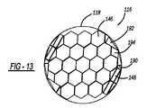
[0056]図13は、これらの特徴を例示する円形開口118に一致するように外側の略円形の周囲を有する、アレイ48および50として同じく使用され得る、ビーム整形器アレイ116の前面図である。アレイ116は、円形形状を提供するために、六角形セル146、長方形セル148、台形セル190、三角形セル192、およびダイアモンド形状セル194を含む様々な特別な形状のビーム整形器セルを含む。 [0056] Figure 13 is a front view of a
[0057]上の実施形態は、ファイバエミッタのアレイを使用するが、別の実施形態は、ダイオードレーザエミッタなどの他のタイプのレーザエミッタを使用し得、エミッタの数は、著しく増加され得るということに留意されたい。より詳細には、ダイオードレーザは、多くの場合、レーザが密接に配置され得る半導体内にリソグラフィで製造される。図14は、採用され得るレーザのタイプを一般化するレーザシステム110の例示であり、エミッタアレイ112は、ビーム整形器アレイ48の入力側に提供され、ダイオードレーザ114を含む。 [0057] Although the above embodiment uses an array of fiber emitters, other embodiments may use other types of laser emitters, such as diode laser emitters, and the number of emitters may be increased significantly. Please note that More specifically, diode lasers are often lithographically fabricated in semiconductors where the lasers can be closely spaced. FIG. 14 is an illustration of a
[0058]ビーム整形器アレイ50の後の所望の出力強度分布がアレイセルの各々についてフラットトップを有することも上で提案されているが、いくつかの応用では、これは望ましくない場合がある。例えば、ビーム整形器アレイ90および100の構成を使用する場合のように、例えば、タイル状のアレイの中心セルが周囲セルよりも高い強度を呈する状態で、遠方場サイドローブを最小にするように周囲付近では低い値へ漸減する強度分布でタイル状のアレイを合成することが望ましい場合、それらの強度がアレイの中心に最も近いセルの縁近くではより大きく、アレイ90などのアレイの外側境界におけるセルの外縁近く、または中心開口部88などの環状リングの内縁近くではより小さくなるように、アレイ内のセルのいくつかまたはすべてに対して内側に強度分布を漸減させることも有利であり得る。これは、アレイの各素子に固有であり得る所望の漸減強度分布をもたらすように2つのビーム整形器アレイ内のビーム整形器の設計を調整することによって達成され得る。 [0058] Although it has also been suggested above that the desired output intensity distribution after the
[0059]ビーム整形器アレイアセンブリ40と同様であるが、位相ロックによるコヒーレント結合を採用しないビーム整形器アレイアセンブリもまた、SBCファイバレーザ増幅器アーキテクチャにおいて採用され得る。図15は、N個の波長チャネル122を含むそのようなアーキテクチャであって、N個の波長チャネル122の各々が、特定のチャネル122のためのファイバ128上に中心波長λを有する連続波周波数変調シードビームを生成するシードビーム源124を有し、各シードビーム源124が異なるビーム波長λ1-λNを生成する、アーキテクチャを例示する、SBCファイバレーザ増幅器システム120の概略ブロック図である。ファイバ128上のシードビームの各々は、Ybドープファイバ増幅器などのファイバ増幅器130へ送られ、増幅器130は、典型的には、光ポンプビーム(図示せず)を受信するファイバ128のドープ増幅部分である。増幅ビームのすべては、ビーム整形器アレイアセンブリ40と同様であるが、ビームのすべてが異なる波長を有することから上で論じられるように位相ロックを提供しない、一次元ビーム整形器アレイアセンブリ132に向けられる。[0059] A beam shaper array assembly similar to beam
[0060]図16は、増幅器システム120から分離された一次元ビーム整形器アレイアセンブリの等尺図である。ビーム整形器アレイアセンブリ132は、結合分散軸および直交する非結合非分散軸では異なり得るビーム整形を提供する、結合軸に沿った1列のファイバを有する一次元アレイである。結合軸に沿って、ビーム整形は、完全に充填された長方形開口を提供することは必ずしも意図されず、むしろハイパーガウス、または入力ビーム形状よりも高いフィルファクタを伴う同様の形状のものであり得、スムーズに漸減した強度プロファイルを伴い得る。ビーム整形器アレイアセンブリ132は、フィルファクタを増加させるために、各ファイバ128からのビームの強度分布を平坦にする。より詳細には、ビーム整形器アレイアセンブリ132は、ファイバ128が結合されるエンドキャップ134、図4A~図4Fに示されるようなアレイ48と同様の様式でビーム強度を広げるビーム整形器を含むビーム整形器アレイ136、および、ビーム整形器アレイアセンブリ132が、波長多様の増幅した高フィルファクタビームのセットを自由空間内に出力するように、アレイ50と同じ様式でビーム広がりを停止するビーム整形器を含むビーム整形器アレイ138を含み、個々のビーム波長λ1-λNは、わずかに異なるエミッタ位置から伝搬している。[0060] FIG. 16 is an isometric view of a one-dimensional beamformer array assembly separated from
[0061]高フィルファクタビームは、多様なビームをコリメートし、それらをSBC格子142上へ、個々のビームのすべてが格子142に衝突し、同じフットプリントに重複するように、向けるコリメーティング光学素子140のセットから反射される。格子142は、個々のビーム波長λ1-λNを空間的に回折し、個々の増幅ビームを結合した出力ビーム144と同じ方向に向ける。[0061] The high fill factor beam collimates the diverse beams and directs them onto the SBC grating 142 such that the individual beams all impinge on the
[0062]SBCビーム品質は、回折格子142からの角度分散により制限される。個々のファイバ増幅器が、周波数変調に起因して有限光学線幅を有するため、パワーは、回折格子142からの回折の後に異なる方向に広がる。これらの異なる方向の広がりが、回折限界角度と比較して著しい場合、ビーム品質は劣化する。ビーム品質の劣化は、回折限界角度を増加させる、結合分散軸に沿って格子142上のビームフットプリントのサイズを減少させることによって最小限にされ得る。格子142はアレイ138のフーリエ面にあるため、これは、アレイ138における個々のビームサイズの増加に対応する。故に、アレイ138の結合軸に沿った高空間フィルファクタは、改善されたビーム品質を提供する。ガウスビームのアレイでは、アレイ138におけるフィルファクタは、損失パワーをもたらすガウスビームのウイングのクリッピングなしに増加することはできない。整形された高フィルファクタビームのアレイ、例えば、ハイパーガウス状のビームのアレイでは、アレイ138の空間フィルファクタは、クリッピング損失を招くことなく増大され得、故に、パワーの損失なしに改善されたビーム品質をもたらす。 [0062] SBC beam quality is limited by the angular dispersion from grating 142 . Since each fiber amplifier has a finite optical linewidth due to frequency modulation, the power spreads in different directions after diffraction from grating 142 . If the spread in these different directions is significant compared to the diffraction limited angle, the beam quality will be degraded. Beam quality degradation can be minimized by decreasing the size of the beam footprint on grating 142 along the coupling dispersion axis, which increases the diffraction limited angle. Since grating 142 is in the Fourier plane of
[0063]レーザシステム120のSBC構成の場合、アレイ138から出力されるビームの形状は、最適には、ビームのすべてについて同一である。しかしながら、ビーム形状は、結合軸および非結合軸に沿って異なり得る。結合軸に沿って、ビームは、角度分散に起因するビーム品質損失を最小限にするためにより高いフィルファクタに提供するように、上で論じられるように整形され得る。非結合軸に沿って、ビームは、例えば、格子142上に近ガウスビームプロファイルを生成するために未整形のままであり得る。これは、2×回折限界よりも大きい角度で遠方場サイドローブ内に回折されるパワーを最小限にすることから、サイズが1×~2×回折限界(DL)である遠方場ターゲットに対するパワーを最大限にするのに有利であり得る。代替的に、ビームは、格子142上に高フィルファクタプロファイルを生成するために非結合軸に沿って整形され得、強度は、望遠鏡開口においてはゼロ近くへと漸減する。これは、望遠鏡開口におけるクリッピング損失を最小限にしながら、サイズが1×回折限界未満であるターゲットに対する遠方場ピーク強度を最大限にするために、ビームディレクタ望遠鏡を完全に充填するのに有利であり得る。格子142の分散的影響は、格子142に入射する整形ビームが分散方向においては狭いが、直交する非分散方向においては広くなるように、ビーム整形器アレイ136および138ならびにコリメーティング光学素子140のセットを選択することによって、出力ビーム品質に対して最小限にされ得る。この非対称構成が、結合ビーム品質の劣化を最小限にしながら、格子142におけるピーク放射輝度を下げる。 [0063] For the SBC configuration of
[0064]エンドキャップ42に結合されるファイバの数は、一般的に、密集したファイバをエンドキャップ42に結合する能力の機械的制限によって制限される。SBCおよびCBCアーキテクチャの両方において結合され得るビームの数は、他の理由で制限される。特に、SBCに必要とされる一次元線形ファイバアレイは、非現実的に大きい場合がある。しかしながら、CBCおよびSBC結合ビームを提供する制限は、CBCアーキテクチャおよびSBCアーキテクチャの両方を組み合わせるハイブリッドファイバレーザ増幅器アーキテクチャによって増加され得る。これは、CBC結合ビームを一方向に、およびSBC結合ビームを直交方向に提供することによって達成され得る。この組み合わされたCBCおよびSBCアーキテクチャは、次いで、上で論じられるビーム整形器アレイアセンブリ40またはビーム整形器アレイアセンブリ132によって提供されるビームフィルファクタにより改善され得る。 [0064] The number of fibers that can be coupled to the
[0065]いくつかのアーキテクチャが、ハイブリッドCBCおよびSBCファイバレーザ増幅器システムにおいてビーム位相を測定するために採用され得る。図17は、1つのそのようなアーキテクチャを例示するハイブリッドCBCおよびSBCファイバレーザ増幅器システム150の概略ブロック図であり、システム10と同じ素子は、同じ参照番号により識別される。システム150は、N個のSBCチャネル152であって、各チャネル152が、波長λiを有するシードビーム源12の別個のグループを含み、式中、iは、範囲1≦i≧Nにある、N個のSBCチャネル152、スプリッタ16、EOM20、およびシステム10内に示されるような増幅器24を含む。そのようなものとして、第iのチャネル152は、別個に増幅され、同じ波長λiのものであるM個の複数シードビームへと分割される単一の波長λiシードビームを含み、M個のEOM20のN個のグループが存在し、チャネル152のすべてが一緒に、異なるビーム波長λ1-λNの各々において増幅されるM×Nシードビームを生成する。M×Nファイバ26のすべては、M×N出力ビーム162を出力する、図2に示されるタイプの入力ビーム整形器アレイ158および出力ビーム整形器アレイ160を含むビーム整形器アレイアセンブリ156の部分であるエンドキャップ154に結合される。[0065] Several architectures can be employed to measure beam phase in hybrid CBC and SBC fiber laser amplifier systems. FIG. 17 is a schematic block diagram of a hybrid CBC and SBC fiber
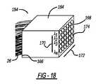
[0066]図18は、システム150から分離されたエンドキャップ154の等角図である。エンドキャップ154は、入力側166および出力側168を有する光学ブロック164を含み、矢印172によって識別される非分散CBC軸は、ブロック164の片側に沿って規定され、図17における紙面に垂直であり、矢印170によって識別される分散SBC軸は、ブロック164の垂直側に沿って規定され、図17における紙面内にある。ファイバ26は、ブロック164の入力側166に光学結合され、各ファイバ26からのビーム174は、ブロック164の出力側168に示され、CBC軸172に沿った各列内のビーム174は、同じ波長λiを有し、チャネル152のうちの1つによって提供され、SBC軸170に沿った各行内のビーム174は、複数の波長λ1-λNを含み、チャネル152のうちの異なるものによって提供される。ビームを受信するビーム整形器アレイ158および160は、ビームの位相ロックがCBC軸172に沿って発生し、ビーム強度平坦化がSBC軸170に沿ってフィルファクタを増加させるために発生するように、上に論じられる様式で構成されるセルおよびビーム整形器を有する。[0066] FIG. 18 is an isometric view of the
[0067]ビーム整形器アレイ160からのM×Nビーム162は、円筒状の光学系196によってコリメートされ、回折格子142と同様の様式で動作する回折格子198上へ向けられる。光学系196は、紙面内で分散SBC軸170に沿って湾曲を有する。光学系196の焦点距離は、格子198からの回折した出力ビームのすべてが、できる限り高い精度で同じ方向に共同伝搬するように、N個の異なる波長λiのすべてが正しい角度で格子198に入射することを確実にするように選択される。結果として、格子198からの結合した出力ビーム176は、ページに直交するCBC軸172に沿ってタイリングされるM個の平行ビームを含み、1つの軸に沿った個々のビーム、および垂直軸に沿った空間的に回折されたビームの位相制御を有する。[0067] M×N beams 162 from
[0068]さらに格子198から反射されるのは、個々の検出器186を有する検出器アレイ184上へレンズ182によって集束される弱鏡面反射0次ビーム180である。ビーム180を含む波長グループは線形アレイ内を異なる角度で伝搬することから、各波長グループのためのレンズ182からの集束ビームは、線に沿って分離され、検出器186の線形アレイへ向けられ得る。N個の検出器186の各々は、各波長グループを含むM個の集束CBCビームの重複を受信する。各検出器186における強度は、位相ロック制御信号と重ね合わされるディザー信号を、例えば、SPGDアルゴリズムを使用して、各波長グループのための対応するEOM20に提供するマルチディザープロセッサ188によって最大限にされる。 [0068] Also reflected from grating 198 is a weakly specularly reflected
[0069]図19は、位相感知および制御特徴を除いて増幅器システム150と同様である別のハイブリッドCBCおよびSBCファイバレーザ増幅器システム200の概略ブロック図であり、システム150と同じ素子は、同じ参照番号により識別される。この実施形態では、スプリッタ16は、各波長グループのための参照として使用されることになる参照ビーム202を提供する。各参照ビーム202は、変調器204によって変調され、変調された参照ビーム202のすべてが、波長分割多重化装置(WDM)206によって単一のファイバ208上へ結合され、次いで、レンズ210によってコリメートされて、大きな多色平面参照ビーム212を形成する。平面参照ビーム212は、サンプル光学素子216によって、ビーム整形器アレイ160から伝送されるM×Nビーム162の小サンプルと結合される。 [0069] Figure 19 is a schematic block diagram of another hybrid CBC and SBC fiber
[0070]結合された参照ビーム212およびサンプリングされたM×Nビーム162は、個々の検出器220を含む2D M×N検出器アレイ218によって受信され、波長フィルタ(図示せず)が、所与の検出器220に意図される正しい波長λi以外の波長を有する参照ビーム212からノイズを除去するためにアレイ218において採用され得る。代替的に、検出器アレイ218は、所与の検出器220に意図される正しい波長以外の波長を有する参照ビームから生じるDC光電流を拒否するためにAC結合され得る。アレイ218内の各検出器220からのヘテロダイン干渉信号は、M個のビームの各グループを各波長λiに位相ロックするために位相補正信号をEOM20に提供するOHDプロセッサ222に伝送される。[0070] The combined
[0071]増幅器システム150および200は特定の位相制御手法を提供するが、これは、他の手法が好適な場合があるという点で非限定的であることに留意されたい。ハイブリッドファイバレーザ増幅器システム150および200における本質的な要素は、CBCビームが、システム10と同様の所望の位相プロファイルと一緒に位相ロックされる必要がある、ということである。ハイブリッドシステム150および200における本質的な差は、CBCビームが一方向のみであり、これは、他の次元におけるビームがスペクトル結合されるためである、ということである。 [0071] Note that although
[0072]上で論じられる様々な実施形態においてビーム整形器アレイアセンブリ40のための必要な光学整列精度を獲得することが非常に困難であることから、ビーム整形器アレイアセンブリ40は、著しいおよび様々な波面収差および誤差がビーム内で発生するのを防ぐのに十分な正確性で製造されない場合があるということが上で述べられた。例えば、ファイバ26をステム44に溶接するための知られている製造プロセスは、一般的に、ビーム偏向をもたらす位置誤差および角度誤差の両方を完全に防ぐには十分に正確ではない。レンズ製造および機械公差からの統合において発生し得るさらなる誤差もまた、発射機アレイビーム偏向をもたらす。誤差は、一般的に、光路に沿った3つの異なる場所において補正され得、具体的には、ファイバ26とステム44との間の溶接継手を変えること、ビーム整形器アレイアセンブリ40を変えること、ならびにトリムビーム整形器アレイ62および66などのトリム板を提供することである。これらの波面収差を補正するための1つのやり方は、上で論じられるように、収差を測定し、トリムビーム整形器アレイ62および66を提供することである。しかしながら、他の技術もまた、収差を補正するために採用され得る。これらの技術のうちのいくつかの詳細な議論は、以下で論じられる。 [0072]Because it is very difficult to obtain the necessary optical alignment accuracy for the beam
[0073]図20は、光学素子、および特にビーム整形器アレイアセンブリ40を製造および補正するための一般的なプロセスを概説するフローチャート図230である。ボックス232で、光学素子、例えば、アセンブリ40は、著しい製造誤差がアセンブリ40内に存在する可能性の高い、安価で低精度の製造プロセスを使用して製造される。アセンブリ40を製造するためのこのプロセスステップの間、ステム44を伴うエンドキャップ42が提供され、ファイバ26は、1Dエミッタアレイなどのエミッタアレイを形成するためにステム44に光学的に溶接される。いくつかの1Dエミッタアレイが、例えば2Dエミッタアレイを形成するために、一緒に組み立てられ得る。1Dまたは2Dエミッタアレイは、次いで、例えば、ビーム整形器アレイ48および50と統合される。ボックス234で、例えばアセンブリ40によって引き起こされる波面誤差は、ビーム整形器アレイ48の平面、ビーム整形器アレイ50の平面、および遠方場平面から、例えば、分布のセンサ上に画像中継を作成する光学系を使用して、測定され、センサは、放射照度分布を測定するためのカメラまたは波面分布を測定するための干渉計であり得る。ボックス236で、誤差を補正するために使用される指示および解決策のために計算が行われる。ボックス238で、好適なプロセスが、ビーム整形器アレイアセンブリ40を再製造すること、スタンドアロン光学トリム板を提供すること、ファイバエミッタ位置および角度トリミングを変化させることなど、指示に基づいて誤差を補正するために実施される。さらなる補正が必要とされる場合、プロセスは、ボックス234へ戻って波面誤差を再度測定する。補正が成功した場合、ビーム整形器アレイアセンブリ40は、正確であり、ボックス240で動作可能である。 [0073] FIG. 20 is a flow chart diagram 230 outlining a general process for manufacturing and correcting optical elements, and in particular beam
[0074]光学素子を製造するための上で論じた様々なステップは、いくつかの好適な方法およびプロセスによって実施され得る。これらのプロセスのうちのいくつかは、以下に論じられ、それらのうちの一部は、Fiber Launcher(ファイバ発射機)という表題の、Goodnoらに対する、2019年4月23日に発行された米国特許第10,267,992号に関連し得、これは、本出願の譲受人に委譲され、参照により本明細書に組み込まれる。 [0074] The various steps discussed above for manufacturing an optical element can be performed by a number of suitable methods and processes. Some of these processes are discussed below, some of them in a U.S. patent entitled Fiber Launcher to Goodno et al., issued Apr. 23, 2019. No. 10,267,992, which is assigned to the assignee of the present application and incorporated herein by reference.
[0075]図21は、機械加工ステム254を有するエンドキャップ252を含む1D光学アセンブリ250の例示であり、機械加工ステム254には、4つが代表として示されるファイバ256が、高電圧電極からのプラズマアーク、CO2レーザビーム、H2+O2フレーム、グラファイトフィラメント、タングステンフィラメントなどの任意の好適な溶接プロセスを使用して光学的に溶接されて、エミッタアレイ248を形成する。アセンブリ250は、矢印268によって表されるグローバル座標に対して較正される、マイクロメートルレベルの解像が可能である定置型光学撮像システム266を含む。エンドキャップ252は、エンドキャップ252と関連付けられた光学基準の精密な並進および撮像によってエンドキャップ座標をグローバル座標268に一致させて、ファイバ256が溶接される各ステム254の端部において撮像点270を規定するために、矢印262によって表される並進ステージ上に位置付けられる。ファイバ256がステム254に溶接される前に、ファイバ256は、矢印260によって表される並進ステージ上に装着され、ファイバ256は、ファイバ256がステム254に溶接されると、並進ステージ260から離脱される。光源258は、撮像システム266および撮像点270を使用してファイバ256をステム254に整列させるために使用されるファイバ256の芯に沿って伝搬する光学モードを有する光ビーム264を提供する。ある特定のステム254に取り付けられるある特定のファイバ256は、ビーム264によって照明され、エンドキャップ座標262に対する光ビームモードの場所を撮像することによって誘導されるその特定のステム254へとステージ260上で移動される。ファイバ先端およびステム先端は、局所的に溶融され、自動化ジグ(図示せず)によって接合される。溶融接合部が冷却された後、ファイバ256の機械的保持が解放される。これらのステップは、ファイバ256のすべてがエンドキャップ252に接続されるまで、各ファイバ256について繰り返される。[0075] Figure 21 is an illustration of a 1D
[0076]ファイバ256がステム254に溶接されると、次のステップは、ファイバ256から放出されているビーム264の各々の場所、配向、および角度を測定することによって、グローバル座標268に対するファイバ256の位置および角度誤差を決定することであり得る。エミッタアレイ248は、精密エンコーダにより所望の場所へ移動され得る。これらの測定値を獲得するために、顕微鏡274が、ビーム264の近接場画像276を提供して、ビーム264の位置誤差を決定するために使用され、望遠鏡278が、ビーム264の遠方場画像280を提供して、ビーム264の指向方向(角度)誤差を決定するために使用される。 [0076] Once the
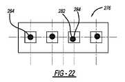
[0077]図22は、ビーム264の近接場画像276の前面図であり、ビーム264は、ファイバ256から放出されており、ビーム264の中心点282と理想のx、y位置284との間のxおよびy方向における誤差を示している。図23は、ターゲット中心点286に対するビーム264の中心点282のx、y方向における誤差を示す遠方場画像280の前面図である。レンズ(図示せず)は、これらの誤差を補正するために使用され得る。 [0077] FIG. 22 is a front view of a near-
[0078]図24は、光学アセンブリ250と同様である1D光学アセンブリ290の例示であり、同じ素子は、同じ参照番号により識別される。アセンブリ290は、例えば、アレイ48または50のうちの1つを表す、レンズ294を有する光ビーム整形器素子292がエンドキャップ252の隣に位置付けられるとき、近接場および遠方場におけるビーム264の位置および角度誤差を決定する。この設計では、素子292は、矢印296によって表される並進ステージに装着される。ビーム264は、一般的に、コリメートされたビーム298として素子292から出力される。コリメートされたビーム298は、ビームスプリッタ300によって分割され、一方のスプリットビームは、近接場画像276を生成するために画像中継光学素子302へ送られ、他方のビームは、遠方場画像280を生成するためにレンズ304によって遠方場内に集束され、近接場画像276および遠方場画像280は、素子292の画像平面にあり、ファイバ256の先端にはなく、画像平面は、ビーム整形器アレイ50にあり得る。 [0078] Figure 24 is an illustration of a 1D
[0079]ビーム264の位置および角度誤差は、干渉法を使用して測定され得る。図25は、これを例示する1D光学アセンブリ310の例示であり、アセンブリ290と同じ素子は、同じ参照番号により識別される。この設計では、干渉計312が、ビームスプリッタ300の下流に提供される。干渉計312において生成される画像316の前面図は、図26に示され、コリメートされたビーム298の各々の干渉パターン318を示す。干渉パターン318の中心と所望の位置との間のオフセット誤差が、ビーム位置および角度を補正するために使用され得る。 [0079] The position and angular error of
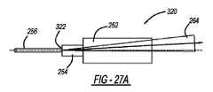
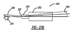
[0080]図27A~図27Dは、ファイバ256のビーム指向偏差角を補正するためのプロセスを示す、エミッタアレイ320の例示であり、アセンブリ290と同じ素子は、同じ参照番号により示される。ビーム264の指向角度誤差は、図27Aに示されるように、上で論じられるものなどの任意の好適なプロセスを使用して測定されて、指向補正を行うためにファイバ256を屈曲する方向および大きさを決定する。測定値は、図27Bに示されるように、角度誤差と反対の方向にファイバ256を屈曲および保持するために、ファイバ256とステム254との間で、数十ミリメートルなど、溶接接合点322から何らかの距離だけ離れたファイバ256に印加されるべき静的力324を決定するために使用され、ビーム264の角度誤差は、ファイバ256が屈曲されるとき変化しない。局所加熱326が、図27Cに示されるように、ガラスを軟化するのに十分であるがガラスを溶融しない任意の好適な技術によって、ファイバ256およびステム254の溶接接合点322近くのステム254に印加される。軟化の際、ガラスは、力324に応答して変形し、力324によって作成される内部応力が緩和されるまでビーム指向角度を変化させる。加熱が停止され、溶接接合点322が冷め、その後、力324が除去される。ガラス変形は、図27Dに示されるように、溶接接合点322におけるファイバ角度変化が理由でビーム指向角度を変化させる。本プロセスは、ビーム指向方向が特定の公差内になるまで繰り返される。 [0080] Figures 27A-27D are an illustration of an
[0081]図28A~図28Cは、ファイバ256の位置誤差を補正するためのプロセスを示す、エミッタアレイ330の例示であり、アセンブリ290および320と同じ素子は、同じ参照番号により識別される。ビーム264のビーム位置誤差332は、ステム形状が変化する方向および大きさを決定するために、図28Aに示されるように、上で論じられるものなどの任意の好適なプロセスを使用して測定される。例えば、非常に高い溶融点を有し、高電圧に対応するサファイア棒による静的力334が、溶接接合点322において、ビーム位置偏差と反対の方向にステム254に印加される。高温ガラスおよび熱源の近接が理由で、ステム254に物理的に接触して力を印加するデバイスは、周囲ガラスに汚染をもたらすことなく、高温および高電圧局所環境に対応している必要がある。図28Bに示されるような局所加熱326は、ガラスを軟化するには十分であるが溶融に到達せずに、ステム254に印加され、こうしてステム254が静的力によって変形することを可能にする。加熱が停止され、溶接接合点322が冷め、その後、力334が除去される。ガラス変形は、図28Cに示されるように、ステム254の形状が理由でビーム位置偏差に変化を引き起こす。本プロセスは、ビーム位置偏差が所望の公差内になるまで繰り返される。 [0081] Figures 28A-28C are an illustration of an
[0082]素子292の適切な位置がエンドキャップ252に対して設定され、固定具(図示せず)によって保持されると、素子292は、例えばアセンブリ40の部分として、エンドキャップ252に接続される必要がある。図29は、対向するサイドブリッジ342および344によって、エンドキャップ252および素子292の側面においてエンドキャップ252に接続される素子292を示す1D光学アセンブリ340の例示であり、アセンブリ290と同じ素子は、同じ参照番号により識別される。図30は、トップブリッジ352によって、エンドキャップ252および素子292の上面においてエンドキャップ252に接続される素子292を示す1D光学アセンブリ350の例示であり、アセンブリ290と同じ素子は、同じ参照番号により識別される。ブリッジ342、344、および352は、糊、溶接、拡散接合、光学接触などの任意の好適な様式によって、エンドキャップ252および素子292に固定され得る。 [0082] Once the proper position of the
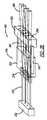
[0083]上で論じられるいくつかの1D光学アセンブリが、上で論じられる技術のいずれかによって構成および整列されていると、1D光学アセンブリのうちの2つ以上は、互いに積層されて2D光学アセンブリを形成し得る。図31は、示されるように、第1列1D光学アセンブリ362、光学アセンブリ362に積層される第2列1D光学アセンブリ364、および光学アセンブリ364に積層される第3列1D光学アセンブリ366を含む、積層された2D光学アセンブリ360の例示であり、アセンブリ340と同じ素子は、同じ参照番号により識別される。好適な精密並進テーブル(図示せず)が、光学アセンブリ362、364、および366を、それらが組み立てられるときに、整列させるために採用され得、これらの光学アセンブリは、任意の好適な技術によって適切な場所に一緒に固定され得る。トリムビーム整形器アレイ62および66などの補正器レンズアセンブリ(図示せず)が、次いで、さらなるビーム整列補正を提供するために採用され得る。 [0083] Once a number of the 1D optical assemblies discussed above have been constructed and aligned by any of the techniques discussed above, two or more of the 1D optical assemblies are stacked together to form a 2D optical assembly. can form FIG. 31 includes a first row 1D
[0084]代替的に、ファイバ256は、2D光学アセンブリの部分である1D光学アセンブリの各々においてエンドキャップ252に整列され、次いで、一緒に積層され得、その後、単一片の2D光学素子がスタックに整列され得る。図32は、互いと積層および整列され、次いで単一の2D素子372と整列される光学アセンブリ362、364、および366を含む光学アセンブリ370を例示し、アセンブリ360と同じ素子は、同じ参照番号により識別される。 [0084] Alternatively, the
[0085]前述の議論は、本開示の例示的な実施形態を開示および説明するにすぎない。当業者は、そのような議論から、ならびに添付の図面および特許請求の範囲から、様々な変更、修正、および変形が、以下の特許請求の範囲に規定されるような本開示の趣旨および範囲から逸脱することなくなされ得ることを容易に認識するものとする。
[0085] The foregoing discussion discloses and describes merely exemplary embodiments of the present disclosure. From such discussion, as well as from the accompanying drawings and claims, those skilled in the art will appreciate that various alterations, modifications and variations fall within the spirit and scope of the disclosure as defined in the following claims. It shall be readily recognized that this may be done without deviation.
Claims (20)
Translated fromJapanese複数のCBCチャネルであって、各々が、中心波長および低フィルファクタプロファイルを有する連続波周波数変調シードビームを生成するシードビーム源を含み、前記シードビームのすべての波長が異なり、各チャネルが、前記シードビームを受信し、前記シードビームを、すべて同じ波長を有する複数のスプリットシードビームへ分割するシードビームスプリッタをさらに含み、各チャネルが、複数の位相変調器であって、各々が、前記スプリットシードビームのうちの1つを受信し、各チャネルの前記スプリットビームのすべてがビーム波面にわたって空間的にコヒーレントな位相を有するように、前記スプリットシードビームの位相を制御する、複数の位相変調器をさらに含み、各チャネルが、複数のファイバ増幅器であって、各々が、前記位相変調されたスプリットシードビームのうちの1つを受信し、各増幅器が、前記スプリットシードビームを増幅し、前記増幅ビームをファイバ上に置く、複数のファイバ増幅器をさらに含む、複数のCBCチャネルと、
入力面を有するエンドキャップを含むビーム整形器アレイアセンブリであって、前記入力面に、前記ファイバのすべてが光学結合され、前記ファイバは、1つのチャネルから前記増幅スプリットシードビームを伝達するファイバが非結合非分散軸に沿って1つの方向に1つの列に配置され、他のチャネルの各々から前記増幅スプリットシードビームを伝達するファイバが結合分散軸に沿って前記1つの列に対して平行列に配置され、その結果として、異なるチャネルからの前記増幅スプリットシードビームのすべてが行列で配置されるように、前記入力面に光学結合され、前記アセンブリが、タイル状に互いに隣接しかつ互いと接触して位置付けられる複数の入力アレイセルを有する入力ビーム整形器アレイをさらに含み、各入力アレイセルは、前記増幅スプリットシードビームのうちの1つを受信し、前記ビームを、前記低フィルファクタプロファイルから高フィルファクタプロファイルへ変換されるように、前記ビームが前記入力ビーム整形器アレイから離れる方へ伝搬する際に拡大させ、前記高フィルファクタプロファイルを、各入力アレイセルの周囲において、等価のフィルファクタガウスビームに可能なものよりも低い値へと漸減させるように、整形される入力ビーム整形器を含み、前記アセンブリは、複数の出力アレイセルを有する出力ビーム整形器アレイをさらに含み、前記複数の出力アレイセルは、各出力アレイセルが入力アレイセルに適合するようにタイル状に互いに隣接しかつ互いと接触して位置付けられ、各出力アレイセルは、前記変換されたビームのうちの1つを受信し、前記出力ビーム整形器アレイが、複数の隣接ビームを前記ビーム間に最小の重複および最小の空隙を伴って有する結合ビームを提供するように、前記変換されたビームの波面を平坦にするように整形される出力ビーム整形器を含む、ビーム整形器アレイアセンブリと、
前記結合ビームを受信するSBC格子であって、前記格子が、個々のビーム波長を空間的に回折し、個々の増幅ビームを結合した出力ビームと同じ方向に向ける、SBC格子と、
を備える、ハイブリッドのコヒーレントビーム結合(CBC)およびスペクトルビーム結合(SBC)ファイバレーザ増幅器システム。A hybrid coherent beam combining (CBC) and spectral beam combining (SBC) fiber laser amplifier system comprising:
a plurality of CBC channels each comprising a seed beam source producing a continuous wave frequency modulated seed beam having a center wavelength and a low fill factor profile, all wavelengths of said seed beams being different, each channel comprising said further comprising a seed beam splitter that receives a seed beam and splits the seed beam into a plurality of split seed beams all having the same wavelength, each channel being a plurality of phase modulators, each of the split seed a plurality of phase modulators for receiving one of the beams and controlling the phase of the split seed beam such that all of the split beams in each channel have spatially coherent phase across the beam wavefront; each channel a plurality of fiber amplifiers, each receiving one of said phase-modulated split seed beams, each amplifier amplifying said split seed beam and generating said amplified beam a plurality of CBC channels further comprising a plurality of fiber amplifiers on the fiber;
A beam shaper array assembly including an end cap having an input face to which all of said fibers are optically coupled, said fibers transmitting said amplified split seed beam from one channel. fibers arranged in a row in one direction along a combined non-dispersion axis and carrying said amplified split seed beam from each of the other channels in a row parallel to said row along a combined dispersion axis; optically coupled to the input surface such that all of the amplified split seed beams from different channels are arranged in rows and columns, the assemblies being tiled adjacent to each other and in contact with each other. further comprising an input beamformer array having a plurality of input array cells positioned at the , each input array cell receiving one of said amplified split seed beams and transforming said beam from said low fill factor profile to a high fill factor profile; expanding the beam as it propagates away from the input beamformer array so as to be converted to a profile, and converting the high fill factor profile to an equivalent fill factor Gaussian beam around each input array cell; the assembly further comprising an output beamformer array having a plurality of output array cells, the plurality of output array cells each output array cells are tiled adjacent to and in contact with each other to match the input array cells, each output array cell receiving one of said transformed beams and said output beamformer array; is shaped to flatten the wavefront of said transformed beam so as to provide a combined beam having a plurality of adjacent beams with minimal overlap and minimal gaps between said beams. a beam shaper array assembly comprising
an SBC grating for receiving said combined beam, said grating spatially diffracting individual beam wavelengths and directing individual amplified beams in the same direction as the combined output beam;
A hybrid coherent beam combining (CBC) and spectral beam combining (SBC) fiber laser amplifier system, comprising:
複数のCBCチャネルであって、各々が、中心波長および円形ガウスプロファイルを有する連続波周波数変調シードビームを生成するシードビーム源を含み、前記シードビームのすべての波長が異なり、各チャネルが、前記シードビームを受信し、前記シードビームを、すべて同じ波長を有する複数のスプリットシードビームへ分割するシードビームスプリッタをさらに含み、各チャネルが、複数の位相変調器であって、各々が、前記スプリットシードビームのうちの1つを受信し、各チャネルの前記スプリットビームのすべてがビーム波面にわたって空間的にコヒーレントな位相を有するように、前記スプリットシードビームの位相を制御する、複数の位相変調器をさらに含み、各チャネルが、複数のファイバ増幅器であって、各々が、前記位相変調されたスプリットシードビームのうちの1つを受信し、各増幅器が、前記スプリットシードビームを増幅し、前記増幅ビームをファイバ上に置く、複数のファイバ増幅器をさらに含む、複数のCBCチャネルと、
入力面を有するエンドキャップを含むビーム整形器アレイアセンブリであって、前記入力面に、前記ファイバのすべてが光学結合され、前記ファイバは、1つのチャネルから前記増幅スプリットシードビームを伝達するファイバが1つの方向に1つの列に配置され、他のチャネルの各々から前記増幅スプリットシードビームを伝達するファイバが前記1つの列に対して平行列に配置され、その結果として、異なるチャネルからの前記増幅スプリットシードビームのすべてが行列で配置されるように、前記入力面に光学結合され、前記アセンブリが、タイル状に互いに隣接して位置付けられる複数の直線入力アレイセルを有する入力ビーム整形器アレイをさらに含み、各入力アレイセルは、前記増幅ビームのうちの1つを前記エンドキャップから受信し、前記ビームを、前記円形ガウスプロファイルからフラットトッププロファイルを有する直線状ビームへ変換されるように、前記ビームが前記入力ビーム整形器アレイから離れる方へ伝搬する際に拡大させるように、および前記フラットトッププロファイルを、各入力アレイセルの周囲においてより低い値へ漸減させるように整形されるビーム整形器を含み、前記アセンブリは、タイル状に互いに隣接して位置付けられる複数の直線出力アレイセルを含む出力ビーム整形器アレイをさらに含み、各出力アレイセルは、前記変換されたビームのうちの1つを受信し、前記出力ビーム整形器アレイが、複数の隣接ビームを前記ビーム間に最小の重複および最小の空隙を伴って有する結合した出力ビームを提供するように、前記ビームに拡大を停止させるように整形される位相板を含む、ビーム整形器アレイアセンブリと、
前記結合ビームを受信するSBC格子であって、前記格子が、個々のビーム波長を空間的に回折し、個々の増幅ビームを結合した出力ビームと同じ方向に向ける、SBC格子と、
を備える、ハイブリッドのコヒーレントビーム結合(CBC)およびスペクトルビーム結合(SBC)ファイバレーザ増幅器システム。A hybrid coherent beam combining (CBC) and spectral beam combining (SBC) fiber laser amplifier system comprising:
a plurality of CBC channels each comprising a seed beam source producing a continuous wave frequency modulated seed beam having a center wavelength and a circular Gaussian profile, all wavelengths of said seed beams being different, each channel being associated with said seed a seed beam splitter that receives a beam and splits the seed beam into a plurality of split seed beams all having the same wavelength, each channel being a plurality of phase modulators, each of the split seed beams and controlling the phase of the split seed beams such that all of the split beams in each channel have spatially coherent phases across beam wavefronts. , each channel a plurality of fiber amplifiers, each receiving one of said phase-modulated split seed beams, each amplifier amplifying said split seed beam and transmitting said amplified beam to a fiber; a plurality of CBC channels further comprising a plurality of overlying fiber amplifiers;
A beam shaper array assembly including an end cap having an input face, wherein all of said fibers are optically coupled to said input face, said fibers being one fiber for transmitting said amplified split seed beam from one channel. Fibers arranged in a row in one direction and carrying said amplified split seed beams from each of the other channels are arranged in parallel rows with respect to said row so that said amplified split seed beams from different channels further comprising an input beam shaper array optically coupled to the input surface such that all of the seed beams are arranged in rows and columns, the assembly having a plurality of linear input array cells tiled adjacent each other; Each input array cell receives one of the amplified beams from the end caps and converts the beam from the circular Gaussian profile to a linear beam with a flat top profile such that the beam is a beamformer shaped to expand as it propagates away from the beamformer array and to taper said flat top profile to a lower value around each input array cell, said assembly comprising: , an output beamformer array including a plurality of linear output array cells tiled adjacent to each other, each output array cell receiving one of said transformed beams; the array includes a phase plate shaped to stop the beams from expanding so as to provide a combined output beam having a plurality of adjacent beams with minimal overlap and minimal gaps between said beams; a beam shaper array assembly;
an SBC grating for receiving said combined beam, said grating spatially diffracting individual beam wavelengths and directing individual amplified beams in the same direction as the combined output beam;
A hybrid coherent beam combining (CBC) and spectral beam combining (SBC) fiber laser amplifier system, comprising:
中心波長および低フィルファクタプロファイルを有する複数の連続波周波数変調シードビームを生成するステップであって、前記シードビームのすべての波長が異なる、ステップと、
各シードビームを、すべて同じ波長を有する複数のスプリットシードビームへ分割するステップと、
同じ波長を有する前記スプリットシードビームのすべてがビーム波面にわたって空間的にコヒーレントな位相を有するように、前記スプリットシードビームの位相を制御するステップと、
位相変調された前記スプリットシードビームを増幅するステップと、
前記増幅ビームを、前記低フィルファクタプロファイルから高フィルファクタプロファイルへ変換されるように、それらが伝搬する際に結合分散軸に沿って拡大させるステップであって、前記高フィルファクタプロファイルは、各ビームの周辺において、等価のフィルファクタガウスビームに可能であるものよりも低い値へ漸減する、ステップと、
異なる波長を有する複数の隣接ビームを、前記ビーム間に最小の重複および最小の空隙を伴って提供するために、前記変換されたビームの波面を平坦にさせるステップと、
前記変換され平坦にされたビームを、個々のビーム波長を空間的に回折し、前記ビームを結合した出力ビームと同じ方向に向けるSBC格子上へ向けるステップと
を含む、方法。
A method for providing coherent beam combining (CBC) and spectral beam combining (SBC), comprising:
generating a plurality of continuous wave frequency modulated seed beams having center wavelengths and low fill factor profiles, wherein all of said seed beams have different wavelengths;
splitting each seed beam into a plurality of split seed beams all having the same wavelength;
controlling the phase of the split seed beams such that all of the split seed beams having the same wavelength have spatially coherent phase across the beam wavefront;
amplifying the phase modulated split seed beam;
expanding the amplified beams along a combined dispersion axis as they propagate such that the amplified beams are transformed from the low fill factor profile to a high fill factor profile, the high fill factor profile corresponding to each beam a step that tapers off to a lower value than is possible for an equivalent fill-factor Gaussian beam in the vicinity of
flattening the wavefront of the converted beams to provide a plurality of adjacent beams having different wavelengths with minimal overlap and minimal air gaps between the beams;
and directing the converted flattened beams onto an SBC grating that spatially diffracts the individual beam wavelengths and directs the beams in the same direction as the combined output beams.
Applications Claiming Priority (3)
| Application Number | Priority Date | Filing Date | Title |
|---|---|---|---|
| US16/592,284 | 2019-10-03 | ||
| US16/592,284US11415810B2 (en) | 2019-10-03 | 2019-10-03 | Hybrid spectrally and coherently combined fiber laser amplifier system including coherent optically monolithic phased array with compact tiles |
| PCT/US2020/050041WO2021067017A1 (en) | 2019-10-03 | 2020-09-10 | Hybrid spectrally and coherently combined fiber laser amplifier system including coherent optically monolithic phased array with compact tiles |
Publications (2)
| Publication Number | Publication Date |
|---|---|
| JP2022551111Atrue JP2022551111A (en) | 2022-12-07 |
| JP7507235B2 JP7507235B2 (en) | 2024-06-27 |
Family
ID=72615962
Family Applications (1)
| Application Number | Title | Priority Date | Filing Date |
|---|---|---|---|
| JP2022520699AActiveJP7507235B2 (en) | 2019-10-03 | 2020-09-10 | A hybrid spectrally and coherently combined fiber laser amplifier system including a coherent optical monolithic phased array with miniature tiles. |
Country Status (5)
| Country | Link |
|---|---|
| US (2) | US11415810B2 (en) |
| EP (1) | EP4038703A1 (en) |
| JP (1) | JP7507235B2 (en) |
| KR (1) | KR20220071965A (en) |
| WO (1) | WO2021067017A1 (en) |
Families Citing this family (7)
| Publication number | Priority date | Publication date | Assignee | Title |
|---|---|---|---|---|
| US11296477B2 (en)* | 2019-05-01 | 2022-04-05 | The United States Of America As Represented By The Secretary Of The Army | Systems, apparatuses and methods for coherent beam combining of fiber laser beams with broadened linewidth |
| IL275783B (en)* | 2020-07-01 | 2021-12-01 | Elbit Systems Electro Optics Elop Ltd | Systems and methods for coherent beam combining |
| US20230152066A1 (en)* | 2021-02-09 | 2023-05-18 | Will Ragan | Efficient transmission of matter and energy via quantum phase modulation |
| IL284740B2 (en)* | 2021-07-08 | 2023-05-01 | Elbit Systems Electro Optics Elop Ltd | Correction optical elements for coherent beam combining systems and systems and methods for coherent beam combining using same |
| CN114236496B (en)* | 2021-10-28 | 2025-05-16 | 深圳阜时科技有限公司 | Transmitter module, optical detection device and electronic equipment |
| EP4249991A1 (en)* | 2022-03-24 | 2023-09-27 | II-VI Delaware, Inc. | Spectral beam combining optical assembly and method of fabrication |
| FR3154512A1 (en) | 2023-10-24 | 2025-04-25 | Cailabs | Coherent optical combining device and system employing such a device for illuminating a far-field target |
Citations (10)
| Publication number | Priority date | Publication date | Assignee | Title |
|---|---|---|---|---|
| JP2004506335A (en)* | 2000-08-09 | 2004-02-26 | コーニンクレッカ フィリップス エレクトロニクス エヌ ヴィ | Laser system |
| JP2006126566A (en)* | 2004-10-29 | 2006-05-18 | Fujitsu Ltd | Collimator array and manufacturing method thereof |
| JP2008040447A (en)* | 2006-07-14 | 2008-02-21 | Fujitsu Ltd | Optical device using lens array |
| JP2009523253A (en)* | 2005-09-15 | 2009-06-18 | ノースロップ グラマン コーポレイション | Method and apparatus for optimizing target intensity distribution propagated from an array coupled to a fiber |
| US20090257054A1 (en)* | 2008-04-04 | 2009-10-15 | Melles Griot, Inc. | Compact, thermally stable fiber-optic array mountable to flow cell |
| US20150036218A1 (en)* | 2013-07-30 | 2015-02-05 | Northrop Grumman Systems Corporation | Hybrid diffractive optical element and spectral beam combination grating |
| US20150234195A1 (en)* | 2014-02-18 | 2015-08-20 | Lockheed Martin Corporation | Apparatus and method for fiber-laser output-beam shaping for spectral beam combination |
| US20180275418A1 (en)* | 2017-03-21 | 2018-09-27 | U.S. Army Research Laboratory Attn: Rdrl-Loc-I | Disposing Aperture-Truncated Radiation of Divergent Beam Fiber Optic Collimators and Arrays |
| WO2019012642A1 (en)* | 2017-07-13 | 2019-01-17 | ギガフォトン株式会社 | Laser system |
| US10267992B1 (en)* | 2017-09-19 | 2019-04-23 | Northrop Grumman Systems Corporation | Fiber launcher |
Family Cites Families (2)
| Publication number | Priority date | Publication date | Assignee | Title |
|---|---|---|---|---|
| US7436588B2 (en) | 2006-10-05 | 2008-10-14 | Northrop Grumman Corporation | Method and system for hybrid coherent and incoherent diffractive beam combining |
| US9735537B1 (en) | 2016-04-12 | 2017-08-15 | Northrop Grumman Systems Corporation | Hybrid spectral and coherent beam combiner utilizing 1D fiber arrays |
- 2019
- 2019-10-03USUS16/592,284patent/US11415810B2/enactiveActive
- 2020
- 2020-09-10KRKR1020227012529Apatent/KR20220071965A/enactivePending
- 2020-09-10JPJP2022520699Apatent/JP7507235B2/enactiveActive
- 2020-09-10EPEP20776285.7Apatent/EP4038703A1/enactivePending
- 2020-09-10WOPCT/US2020/050041patent/WO2021067017A1/ennot_activeCeased
- 2022
- 2022-06-30USUS17/810,037patent/US11681151B2/enactiveActive
Patent Citations (10)
| Publication number | Priority date | Publication date | Assignee | Title |
|---|---|---|---|---|
| JP2004506335A (en)* | 2000-08-09 | 2004-02-26 | コーニンクレッカ フィリップス エレクトロニクス エヌ ヴィ | Laser system |
| JP2006126566A (en)* | 2004-10-29 | 2006-05-18 | Fujitsu Ltd | Collimator array and manufacturing method thereof |
| JP2009523253A (en)* | 2005-09-15 | 2009-06-18 | ノースロップ グラマン コーポレイション | Method and apparatus for optimizing target intensity distribution propagated from an array coupled to a fiber |
| JP2008040447A (en)* | 2006-07-14 | 2008-02-21 | Fujitsu Ltd | Optical device using lens array |
| US20090257054A1 (en)* | 2008-04-04 | 2009-10-15 | Melles Griot, Inc. | Compact, thermally stable fiber-optic array mountable to flow cell |
| US20150036218A1 (en)* | 2013-07-30 | 2015-02-05 | Northrop Grumman Systems Corporation | Hybrid diffractive optical element and spectral beam combination grating |
| US20150234195A1 (en)* | 2014-02-18 | 2015-08-20 | Lockheed Martin Corporation | Apparatus and method for fiber-laser output-beam shaping for spectral beam combination |
| US20180275418A1 (en)* | 2017-03-21 | 2018-09-27 | U.S. Army Research Laboratory Attn: Rdrl-Loc-I | Disposing Aperture-Truncated Radiation of Divergent Beam Fiber Optic Collimators and Arrays |
| WO2019012642A1 (en)* | 2017-07-13 | 2019-01-17 | ギガフォトン株式会社 | Laser system |
| US10267992B1 (en)* | 2017-09-19 | 2019-04-23 | Northrop Grumman Systems Corporation | Fiber launcher |
Also Published As
| Publication number | Publication date |
|---|---|
| US11415810B2 (en) | 2022-08-16 |
| EP4038703A1 (en) | 2022-08-10 |
| US20210103155A1 (en) | 2021-04-08 |
| WO2021067017A1 (en) | 2021-04-08 |
| US20220334401A1 (en) | 2022-10-20 |
| US11681151B2 (en) | 2023-06-20 |
| JP7507235B2 (en) | 2024-06-27 |
| KR20220071965A (en) | 2022-05-31 |
Similar Documents
| Publication | Publication Date | Title |
|---|---|---|
| JP7674345B2 (en) | Optical monolithic beam shaper array with miniature tiles. | |
| US11681152B2 (en) | Coherent beam combining (CBC) fiber laser amplifier system | |
| US11681151B2 (en) | Hybrid coherent beam combining (CBC) and spectral beam combining (SBC) fiber laser amplifier system | |
| US11932567B2 (en) | System and method for fabricating an optical element | |
| US11698537B2 (en) | Spectrally combined fiber laser amplifier system and method | |
| EP4204868A1 (en) | Method for assembling a hollow core optical fiber array launcher | |
| EP4204869B1 (en) | Hollow core optical fiber array launcher |
Legal Events
| Date | Code | Title | Description |
|---|---|---|---|
| A621 | Written request for application examination | Free format text:JAPANESE INTERMEDIATE CODE: A621 Effective date:20230705 | |
| A131 | Notification of reasons for refusal | Free format text:JAPANESE INTERMEDIATE CODE: A131 Effective date:20240322 | |
| A977 | Report on retrieval | Free format text:JAPANESE INTERMEDIATE CODE: A971007 Effective date:20240327 | |
| A521 | Request for written amendment filed | Free format text:JAPANESE INTERMEDIATE CODE: A523 Effective date:20240530 | |
| TRDD | Decision of grant or rejection written | ||
| A01 | Written decision to grant a patent or to grant a registration (utility model) | Free format text:JAPANESE INTERMEDIATE CODE: A01 Effective date:20240604 | |
| A61 | First payment of annual fees (during grant procedure) | Free format text:JAPANESE INTERMEDIATE CODE: A61 Effective date:20240617 |