JP2022547578A - Intravascular coil and method of making same - Google Patents
Intravascular coil and method of making sameDownload PDFInfo
- Publication number
- JP2022547578A JP2022547578AJP2022516061AJP2022516061AJP2022547578AJP 2022547578 AJP2022547578 AJP 2022547578AJP 2022516061 AJP2022516061 AJP 2022516061AJP 2022516061 AJP2022516061 AJP 2022516061AJP 2022547578 AJP2022547578 AJP 2022547578A
- Authority
- JP
- Japan
- Prior art keywords
- loop
- coil
- intravascular
- loops
- rotation
- Prior art date
- Legal status (The legal status is an assumption and is not a legal conclusion. Google has not performed a legal analysis and makes no representation as to the accuracy of the status listed.)
- Granted
Links
Images


Classifications
- A—HUMAN NECESSITIES
- A61—MEDICAL OR VETERINARY SCIENCE; HYGIENE
- A61B—DIAGNOSIS; SURGERY; IDENTIFICATION
- A61B17/00—Surgical instruments, devices or methods
- A61B17/12—Surgical instruments, devices or methods for ligaturing or otherwise compressing tubular parts of the body, e.g. blood vessels or umbilical cord
- A61B17/12022—Occluding by internal devices, e.g. balloons or releasable wires
- A61B17/12131—Occluding by internal devices, e.g. balloons or releasable wires characterised by the type of occluding device
- A61B17/1214—Coils or wires
- A61B17/12145—Coils or wires having a pre-set deployed three-dimensional shape
- A—HUMAN NECESSITIES
- A61—MEDICAL OR VETERINARY SCIENCE; HYGIENE
- A61B—DIAGNOSIS; SURGERY; IDENTIFICATION
- A61B17/00—Surgical instruments, devices or methods
- A61B17/16—Instruments for performing osteoclasis; Drills or chisels for bones; Trepans
- A61B17/1697—Instruments for performing osteoclasis; Drills or chisels for bones; Trepans specially adapted for wire insertion
- B—PERFORMING OPERATIONS; TRANSPORTING
- B21—MECHANICAL METAL-WORKING WITHOUT ESSENTIALLY REMOVING MATERIAL; PUNCHING METAL
- B21F—WORKING OR PROCESSING OF METAL WIRE
- B21F3/00—Coiling wire into particular forms
- B—PERFORMING OPERATIONS; TRANSPORTING
- B21—MECHANICAL METAL-WORKING WITHOUT ESSENTIALLY REMOVING MATERIAL; PUNCHING METAL
- B21F—WORKING OR PROCESSING OF METAL WIRE
- B21F3/00—Coiling wire into particular forms
- B21F3/02—Coiling wire into particular forms helically
- B—PERFORMING OPERATIONS; TRANSPORTING
- B21—MECHANICAL METAL-WORKING WITHOUT ESSENTIALLY REMOVING MATERIAL; PUNCHING METAL
- B21F—WORKING OR PROCESSING OF METAL WIRE
- B21F3/00—Coiling wire into particular forms
- B21F3/12—Coiling wire into particular forms of interconnected helical springs
- B—PERFORMING OPERATIONS; TRANSPORTING
- B21—MECHANICAL METAL-WORKING WITHOUT ESSENTIALLY REMOVING MATERIAL; PUNCHING METAL
- B21F—WORKING OR PROCESSING OF METAL WIRE
- B21F45/00—Wire-working in the manufacture of other particular articles
- B21F45/008—Wire-working in the manufacture of other particular articles of medical instruments, e.g. stents, corneal rings
- A—HUMAN NECESSITIES
- A61—MEDICAL OR VETERINARY SCIENCE; HYGIENE
- A61B—DIAGNOSIS; SURGERY; IDENTIFICATION
- A61B17/00—Surgical instruments, devices or methods
- A61B2017/00526—Methods of manufacturing
Landscapes
- Health & Medical Sciences (AREA)
- Engineering & Computer Science (AREA)
- Surgery (AREA)
- Life Sciences & Earth Sciences (AREA)
- Mechanical Engineering (AREA)
- General Health & Medical Sciences (AREA)
- Heart & Thoracic Surgery (AREA)
- Public Health (AREA)
- Nuclear Medicine, Radiotherapy & Molecular Imaging (AREA)
- Biomedical Technology (AREA)
- Medical Informatics (AREA)
- Molecular Biology (AREA)
- Animal Behavior & Ethology (AREA)
- Veterinary Medicine (AREA)
- Vascular Medicine (AREA)
- Reproductive Health (AREA)
- Orthopedic Medicine & Surgery (AREA)
- Oral & Maxillofacial Surgery (AREA)
- Dentistry (AREA)
- Surgical Instruments (AREA)
Abstract
Translated fromJapaneseDescription
Translated fromJapanese (背景)
動脈瘤および他の類似の血管障害の治療は、多くの場合、動脈瘤または他の血管構造の空間内への血管内コイルの設置を伴う。動脈瘤では、この空間は、多くの場合、球状である。しかしながら、いくつかの事例では、それは、楕円形であり得るか、または2つもしくはそれより多くの小葉突出部(多くの場合、二葉性または多葉性動脈瘤と呼ばれる)を有し得る。従来のコイルシステムは、骨組コイル、充填コイル、および仕上げコイル等の多様な形状およびタイプのコイルを有する。(background)
Treatment of aneurysms and other similar vascular disorders often involves placement of an endovascular coil within the space of the aneurysm or other vascular structure. In an aneurysm, this space is often spherical. However, in some cases it may be oval or have two or more lobular protrusions (often called bilobular or multilobal aneurysms). Conventional coil systems have coils of various shapes and types, such as skeletal coils, filling coils, and finishing coils.
骨組コイルは、典型的には、動脈瘤内に設置される最初のコイルであり、動脈瘤によって形成された空間内に適合するように設計された複雑なまたは3次元の形状を有する。骨組コイルは、以下の機能、すなわち、(1)動脈瘤の閉じ込め空間(confines)内に安定な骨組を提供する機能であって、その中に後続コイルが設置され得る、機能と、(2)動脈瘤の頸部にわたって適正なループ適用範囲を提供する機能と、(3)ループが動脈瘤の中心を横切る(追加のカテーテル操作を必要とし、手順を長引かせ、動脈瘤破裂のリスクを増加させる区画を動脈瘤内に生成し得る)ことを防止する機能とを実施するために使用され得る。 A skeletal coil is typically the first coil placed within an aneurysm and has a complex or three-dimensional shape designed to fit within the space created by the aneurysm. The scaffold coil has the following functions: (1) to provide a stable scaffold within the confines of the aneurysm into which subsequent coils may be placed; and (2). (3) the loop crosses the center of the aneurysm, requiring additional catheter manipulation, prolonging the procedure and increasing the risk of aneurysm rupture; It can be used to perform functions such as preventing compartments from forming within the aneurysm.
加えて、いくつかの事例では、骨組コイルがマイクロカテーテル内で最小限にまたは容認可能に低い摩擦を伴って送達されることが望ましい。多くの骨組コイルが、球状動脈瘤を治療するときにこれらの機能を実施し得る球状形状を有する。しかしながら、それらは、多くの場合、動脈瘤が非球状(例えば、楕円形または二葉性)であるとき、不適正である。他の骨組コイルが非球状動脈瘤内に適合する複雑な形状を有する。しかしながら、そのようなコイルは、典型的には、独立軸を伴って整列させられたループから成り、動脈瘤自体によって束縛されるように設計されている。このタイプの形状は、顕著なポテンシャルエネルギーを伴う骨組コイルをもたらす。これは、その非抑制状態では骨組コイルが動脈瘤の寸法を優に越えて拡張し、したがって、空間内に束縛されると動脈瘤壁に力を直接伝達する傾向にあることを意味する。この力は、動脈瘤壁を傷付けるためには不十分であり得る一方、骨組コイルを後続コイルの設置時に移動しやすい状態にする。多くの場合、そのようなコイルは、偏移し、ループが親動脈の中に突出することを潜在的に引き起こし、それは、補助および/または緊急療法を必要とする。加えて、いくつかの骨組コイルの複雑な形状は、多くの場合、それらがマイクロカテーテルを通して送達されるときに生成される摩擦を増加させる。 Additionally, in some cases, it is desirable that the skeletal coil be delivered within the microcatheter with minimal or acceptably low friction. Many skeletal coils have spherical shapes that can perform these functions when treating spherical aneurysms. However, they are often inappropriate when the aneurysm is non-spherical (eg, oval or bilobate). Other skeletal coils have complex shapes that fit within non-spherical aneurysms. However, such coils typically consist of loops aligned with independent axes and are designed to be constrained by the aneurysm itself. This type of geometry results in a skeletal coil with significant potential energy. This means that in its unconstrained state the skeletal coil expands well beyond the dimensions of the aneurysm and therefore tends to transmit force directly to the aneurysm wall when constrained in space. While this force may be insufficient to damage the aneurysm wall, it leaves the skeletal coil amenable to movement during placement of subsequent coils. In many cases, such coils will deviate, potentially causing the loop to protrude into the parent artery, which requires adjuvant and/or emergency therapy. Additionally, the complex shape of some skeletal coils often increases the friction created when they are delivered through a microcatheter.
複雑な3D形状を伴う血管内コイルは、それらが骨組コイル、充填コイル、または仕上げコイルのいずれであったとしても、それらが非常に具体的な3D形状を形成するように設計および熱硬化されるため、種々の不規則的形状のおよび多葉性動脈瘤を良好に充填しない。したがって、従来の複雑な形状の血管内コイルは、動脈瘤の形状がコイルの複雑な形状と良好に合致しないとき、動脈瘤のあるエリアまたはボリュームを非充填のままにし得る。当然のことながら、無作為に選択された複雑な形状のコイルが不規則的形状の動脈瘤を妥当な容認可能な程度まで充填し得る可能性は存在する。しかしながら、正しく設計および工作された血管内コイルは、任意の不規則的形状の動脈瘤を予測可能かつ確実に充填し得、そのため、成功手順に関する可能性にあまり依拠しない。故に、予測可能で、確実で、かつ実質的に完全な方式において任意の不規則的形状のおよび多葉性動脈瘤を充填する血管内コイルが、必要とされる。 Intravascular coils with complex 3D shapes, whether they are skeletal coils, filling coils, or finishing coils, are designed and heat-set so that they form very specific 3D shapes Therefore, it does not fill various irregularly shaped and multilobal aneurysms well. Thus, conventional complex shaped endovascular coils can leave an aneurysm area or volume unfilled when the aneurysm shape does not match well with the complex shape of the coil. Of course, the possibility exists that a randomly selected complex shaped coil could fill an irregularly shaped aneurysm to a reasonably acceptable degree. However, correctly designed and engineered endovascular coils can predictably and reliably fill any irregularly shaped aneurysm, and thus rely less on the likelihood of a successful procedure. Therefore, there is a need for an endovascular coil that fills any irregularly shaped and multilobar aneurysm in a predictable, reliable, and substantially complete manner.
(概要)
捻れた8の字形状を有する血管内コイルの例示的実施形態が、開示される。血管内コイルは、第1のループと、第2のループと、第1のループの一部が第2のループの一部に遷移する変曲領域とを含む。(Overview)
An exemplary embodiment of an intravascular coil having a twisted figure eight shape is disclosed. The intravascular coil includes a first loop, a second loop, and an inflection region where a portion of the first loop transitions to a portion of the second loop.
第2のループは、第1の軸について第1の回転度だけ回転させられる。第1の軸は、第1のループの主軸に実質的に平行である。第1の回転度は、5~90度の範囲であり得る。いくつかの実施形態では、第1の回転度は、45度である。血管内コイルの第1および第2のループは、8の字パターンに配置され得る。 The second loop is rotated a first degree of rotation about the first axis. The first axis is substantially parallel to the major axis of the first loop. The first degree of rotation can range from 5 to 90 degrees. In some embodiments, the first degree of rotation is 45 degrees. The first and second loops of the intravascular coil may be arranged in a figure eight pattern.
第2のループは、第2の軸について第2の回転度だけさらに回転させられ得る。第1および第2の軸は、相互に非平行であるが、両方とも、第1のループが配置されている平面である第1のループの一次平面上に位置している。第2のループの第2の回転度は、5~45度の範囲を有し得る。これは、第2のループが8の字の長軸について捻れながら、同一参照軸からある角度でオフセットすることを引き起こす。 The second loop may be further rotated by a second degree of rotation about the second axis. The first and second axes are non-parallel to each other, but both lie in the primary plane of the first loop, which is the plane in which the first loop is located. The second degree of rotation of the second loop can have a range of 5-45 degrees. This causes the second loop to be offset at an angle from the same reference axis while twisting about the long axis of the figure eight.
いくつかの実施形態では、第2のループは、第2のループの一次平面の上方および下方にうねる起伏トレースパターンを有し得る。トレースパターンは、複数の場所で第2のループの一次平面を突き抜け、横切り得る。血管内コイルは、第1の断面を伴う第1のループと、第2の断面を伴う第2のループとを加えて有し得る。第1および第2の断面は、同一であることも、またはそれらが異なることもあり得る。断面は、円形、多角形、または楕円形の形状を有し得る。第2のループは、第1のループのワイヤより小さい直径を有するワイヤを用いて作製されることもあり得る。 In some embodiments, the second loop may have an undulating trace pattern that undulates above and below the primary plane of the second loop. The trace pattern may penetrate and cross the primary plane of the second loop at multiple locations. The intravascular coil may additionally have a first loop with a first cross-section and a second loop with a second cross-section. The first and second cross-sections can be the same or they can be different. A cross-section can have a circular, polygonal, or elliptical shape. The second loop could also be made with wire having a smaller diameter than the wire of the first loop.
血管内コイルの変曲領域は、捻れ得、重複し得る。変曲領域では、第1のループの一部が、両方のループが閉ループとなるように重複し、第2のループの一部に接触し得る。代替として、第1のループの一部は、捻れており、重複するが、相互に接触しないことがあり得、すなわち、変曲領域を開放領域として残し得る。 The inflection regions of the endovascular coil can twist and overlap. In the inflection region, a portion of the first loop may overlap and touch a portion of the second loop such that both loops are closed loops. Alternatively, a portion of the first loop may be twisted and overlapped but not touching each other, ie leaving the inflection area as an open area.
血管内コイルは、複数の第1および第2のループ対を有し得る。各ループ対は、変曲領域において連続的に接続され、前および/または次のループ対にわたって積層する。血管内コイルは、多くのループ対(例えば、2~100)を有し得る。血管内コイルの遠位端によって形成された1つまたは複数のループ対は、異なるワイヤ属性を有し得る。例えば、血管内コイルは、40cmの全長を有し得、最後の5~10cmは、異なるワイヤ属性を有し得る。ワイヤ属性は、ワイヤの剛性、断面形状、直径、または繊維延在部/突出部等の他の外部特徴であり得る。ループ対は、第1および第2のループを備える。 The intravascular coil can have multiple first and second loop pairs. Each loop pair is continuously connected in the region of inflection and stacks over the previous and/or next loop pair. An intravascular coil can have many loop pairs (eg, 2-100). One or more loop pairs formed by the distal end of the intravascular coil may have different wire attributes. For example, an intravascular coil may have a total length of 40 cm, with the last 5-10 cm having different wire attributes. Wire attributes can be wire stiffness, cross-sectional shape, diameter, or other external features such as fiber extensions/protrusions. A loop pair comprises first and second loops.
第1および第2のループのうちの1つは、ループの中に統合された1つまたは複数の応力点を有し得る。応力点のうちの1つまたは複数は、第1または第2のループの半径の0.001~0.5の屈曲半径を含み得る。 One of the first and second loops may have one or more stress points integrated within the loop. One or more of the stress points may include a bend radius of 0.001 to 0.5 of the radius of the first or second loop.
第1の主軸を有する第1のループと、第1のループに接続されている第2のループであって、第2の主軸を有する第2のループとを含む塞栓コイルも、開示され、第1および第2の主軸は、相互に実質的に平行であり、第2のループは、第2の主軸について回転させられ、第1および第2のループは、捻れた8の字形状を形成する。 An embolic coil is also disclosed that includes a first loop having a first major axis and a second loop connected to the first loop, the second loop having a second major axis, The first and second major axes are substantially parallel to each other, the second loop is rotated about the second major axis, and the first and second loops form a twisted figure eight shape. .
血管内コイルを製造する方法も、開示される。方法は、コイルワイヤの第1の端部をマンドレルの第1のロッドに固定することであって、マンドレルは、第1のロッドおよび第2のロッドを備える、ことと、ワイヤを第1および第2のロッドの周囲に配索し、複数の8の字ワイヤパターンを第1および第2のロッド上に生成することと、第1および第2のロッドのうちの1つを回転点について第1の回転度だけ回転させることであって、回転点は、複数の8の字ワイヤパターンのうちの1つの長軸上に実質的に位置する、ことと、第1の回転度だけマンドレル内で回転させられながら、複数の8の字ワイヤパターンを熱硬化させることとを含む。 A method of manufacturing an intravascular coil is also disclosed. The method includes securing a first end of a coil wire to a first rod of a mandrel, the mandrel comprising a first rod and a second rod; two rods to create a plurality of figure-of-eight wire patterns on the first and second rods; degrees of rotation, wherein the point of rotation is substantially located on the longitudinal axis of one of the plurality of figure eight wire patterns; and rotating within the mandrel the first degree of rotation. and heat setting the plurality of figure-eight wire patterns while being pressed.
本明細書に記載の特徴および利点は、全てを包含するわけではなく、特に、多くの追加の特徴および利点が、図面、明細書、および特許請求の範囲に照らして当業者に明白である。さらに、本明細書において使用される用語は主に可読性および教示目的のために選択されており、開示される主題を境界または限局するように選択されていない場合があることに留意されたい。 The features and advantages described herein are not all-inclusive, and in particular many additional features and advantages will be apparent to those skilled in the art in light of the drawings, specification, and claims. Additionally, it should be noted that the terminology used herein has been chosen primarily for readability and instructional purposes and may not have been chosen to demarcate or confine the disclosed subject matter.
(図面の簡単な説明)
前述の概要および以下の詳細な説明は、付属の図面と併せて読まれると、より良好に理解される。本明細書に組み込まれ、本明細書の一部を形成する付属の図面は、複数の実施形態を図示しており、記載とともに関連原理を説明し、関連技術(単数または複数)における当業者が開示される技術を作製および使用することを可能にする役割をさらに果たす。(Brief description of the drawing)
The foregoing general description and the following detailed description are better understood when read in conjunction with the accompanying drawings. The accompanying drawings, which are incorporated in and form a part of this specification, illustrate several embodiments and, together with the description, explain related principles and enable persons of ordinary skill in the relevant art(s) to It further serves to enable one to make and use the disclosed technology.
図および以下の説明は、例証のみによってある実施形態を説明している。当業者は、以下の説明から、本明細書に図示される構造および方法の代替実施形態が本明細書に説明される原理から逸脱することなく採用され得ることを容易に認識する。ここで、参照が、いくつかの実施形態に対して詳細になされ、その実施例が、付属の図に図示されている。実践可能である場合は常に、類似または同様の参照番号が図において使用され、類似または同様の機能性を示し得ることに留意されたい。 The figures and the following description describe certain embodiments by way of illustration only. Those skilled in the art will readily recognize from the following description that alternative embodiments of the structures and methods illustrated herein can be employed without departing from the principles described herein. Reference will now be made in detail to several embodiments, examples of which are illustrated in the accompanying figures. Note that wherever practicable, similar or similar reference numbers may be used in the figures to indicate similar or similar functionality.
(詳細な説明)
(概説)
捻れた8の字形状を呈する血管内/塞栓コイルが、本明細書に開示される。8の字形状は、8の字形状の上側および下側部分を形成する2つの丸みを帯びた部分を有する。捻れた8の字コイルにおいて、丸みを帯びた部分のうちの一方は、他方の回転させられていない丸みを帯びた部分に対して捻れているか、または回転させられている。回転させられた丸みを帯びた部分は、限定ではないが、1~179度の範囲等の任意の回転度だけ回転させられ得る。いくつかの実施形態では、回転させられた丸みを帯びた部分は、45度だけ回転させられている。別の実施例では、回転させられた丸みを帯びた部分は、90度だけ回転させられている。8の字コイルの丸みを帯びた部分は、円形、多角形、または楕円形であり得る。(detailed explanation)
(Overview)
Disclosed herein is an endovascular/embolic coil that exhibits a twisted figure-eight shape. The figure 8 shape has two rounded portions forming upper and lower portions of the figure 8 shape. In a twisted figure-eight coil, one of the rounded portions is twisted or rotated relative to the other, non-rotated rounded portion. The rotated rounded portion may be rotated by any degree of rotation, such as, but not limited to, a range of 1-179 degrees. In some embodiments, the rotated rounded portion is rotated by 45 degrees. In another embodiment, the rotated rounded portion is rotated by 90 degrees. The rounded portion of the figure eight coil can be circular, polygonal, or elliptical.
いくつかの実施形態では、回転させられた丸みを帯びた部分は、回転させられていない丸みを帯びた部分の半主軸に実質的に平行な軸について回転させられている。回転させられていない丸みを帯びた部分が円形である場合、半主軸は、直径である。この場合、回転させられた丸みを帯びた部分は、2つの丸みを帯びた部分の共通軸または長軸について回転させられている。換言すると、回転させられた丸みを帯びた部分は、両方の丸みを帯びた部分の共通主軸である真っ直ぐな8の字の長軸について回転させられている。8の字形状のコイルの丸みを帯びた部分の相対位置および回転に関するさらなる詳細が、下記に提供される。 In some embodiments, the rotated rounded portion is rotated about an axis substantially parallel to the semi-major axis of the non-rotated rounded portion. If the unrotated rounded portion is circular, the semi-major axis is the diameter. In this case the rotated rounded portion is rotated about the common or major axis of the two rounded portions. In other words, the rounded portion being rotated is rotated about the major axis of the straight figure 8, which is the common major axis of both rounded portions. Further details regarding the relative positions and rotation of the rounded portions of the figure-eight coil are provided below.
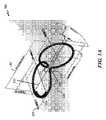
塞栓コイルは、その最小エネルギー状態または二次構成において捻れた8の字形状を有するように構成されている。コイルは、塞栓コイルがスリーブまたはカテーテルによって阻止されていないとき、最小エネルギー状態を取得するためにその二次構成に戻るように構成され、二次構成は、捻れた8の字の形状である。塞栓コイルが(体外で)平坦面上に出されたとき、コイルは、相互の上に積層する8の字の複数の層を形成する一方で概して平坦に見え、すなわち、回転させられても捻れてもいないように見える。これは、平坦面の拘束と、塞栓コイルの回転させられた丸みを帯びた部分を平坦面に向かって引き寄せる重力とに起因する。同塞栓コイルは、身体の内側(例えば、動脈瘤の内側)で展開されたとき、捻れた8の字形状を有する(例えば、図1を参照)。動脈瘤または動脈の内側の体液が、いくらかの浮力を提供し、それによって、塞栓コイルを浮かせ、塞栓コイルが、捻れた/回転させられた8の字形状であるその最小エネルギー状態および形状を形成することを可能にする。実験的データは、塞栓コイルが動脈瘤(例えば、不規則的形状(例えば、多葉性)の動脈瘤)を充填すると、捻れがコイルの充填挙動にさらなる無作為性および変動性を追加することを示す。充填挙動の追加された無作為性および変動性は、捻れた8の字塞栓コイルが、真っ直ぐな8の字形状のコイル等の他の従来の塞栓コイルより良好に不規則的形状の動脈瘤の空隙を充填することを可能にする。 The embolic coil is configured to have a twisted figure eight shape in its lowest energy state or secondary configuration. The coil is configured to return to its secondary configuration to obtain a minimum energy state when the embolic coil is not blocked by a sleeve or catheter, the secondary configuration being a twisted figure eight shape. When the embolic coil is exposed (extracorporeally) on a flat surface, the coil appears generally flat while forming multiple layers of figure eights that stack on top of each other, i.e., does not twist even when rotated. looks like it's not. This is due to the constraint of the flat surface and the force of gravity pulling the rotated rounded portion of the embolic coil toward the flat surface. The embolic coil has a twisted figure-eight shape when deployed inside the body (eg, inside an aneurysm) (see, eg, FIG. 1). Fluid inside the aneurysm or artery provides some buoyancy, thereby floating the embolic coil, which forms its lowest energy state and shape which is a twisted/rotated figure eight shape. make it possible to Experimental data show that when an embolic coil fills an aneurysm (e.g., an irregularly shaped (e.g., multilobed) aneurysm), twist adds additional randomness and variability to the coil's filling behavior. indicates The added randomness and variability of filling behavior indicates that the twisted figure-eight embolic coil performs better than other conventional embolic coils, such as straight figure-eight coils, for irregularly shaped aneurysms. Allows filling of voids.
いくつかの実施形態では、捻れた8の字コイルは、限定ではないが、近位部分および遠位部分等の複数の部分を有し得る。遠位部分は、異なる材料を用いて、または同一材料であるが異なる属性を伴う材料を用いて作製され得、異なる属性は、限定ではないが、剛性(例えば、直径、厚み)、軟度、および他の外部特徴(例えば、繊維突出部)等である。いくつかの実施形態では、遠位部分は、近位部分より薄く、近位部分より柔軟であり得る。逆に、近位部分は、遠位部分より薄く、遠位部分より柔軟であり得る。 In some embodiments, the twisted figure-eight coil can have multiple portions, such as, but not limited to, a proximal portion and a distal portion. The distal portion can be made using different materials, or using the same material but with different attributes, which include, but are not limited to, stiffness (e.g., diameter, thickness), softness, and other external features (eg, fiber protrusions), and the like. In some embodiments, the distal portion can be thinner and more flexible than the proximal portion. Conversely, the proximal portion may be thinner and more flexible than the distal portion.
(捻れた8の字)
図1は、本開示のいくつかの実施形態による捻れた8の字形状を伴う血管内コイル100を図示している。血管内コイル100は、第1のループ105と、第2のループ110とを含む。第1のループ105は、第1の平面115上に配置されている。第2のループ110は、第1の平面115に対してあるオフセット角度にある第2の平面120上に配置されている。第1の平面115と第2の平面120との間のオフセット角度は、1~179度の範囲であり得る。いくつかの実施形態では、オフセット角度は、概ね90度である。別の実施形態では、オフセット角度は、45度である。示されているように、オフセット角度は、第1および第2のループ105、110の両方の共通軸である長軸130について第2のループ110が回転させられている角度である。いくつかの実施形態では、オフセット角度は、第2のループ110の第2の軸についての回転角度であり得る。第2の軸(示されていない)は、軸130と同一であり得るか、または、それは、軸130に実質的に平行であり得る。ループ110が楕円形である場合、第2の軸は、ループ110の半主軸であり得る。第2の軸は、コイル全体の長軸であり得る。(twisted figure 8)
FIG. 1 illustrates an
図1Bは、異なる参照環境において、捻れた8の字コイルのループの空間的関係を図示するために役立つように血管内コイル100を図示している。第1および第2のループ105、110間の空間的関係は、第1のループ105が配置されている平面115と、第2のループ110の回転軸150とによって画定され得る。回転軸150は、平面115上に配置され、第1のループ105の主軸および直径に実質的に平行であり得る。回転軸150は、第1のループ105に関する同一主軸でもあり得る。言い換えると、軸150は、コイル100の長軸130と同一であり得る。示されているように、第2のループ110は、回転軸150について90度だけ回転させられている。しかしながら、第2のループ110は、軸150について、限定ではないが、5、10、20、25、30、35、40、45、50、55、および60度等の任意の度だけ回転させられ得る。 FIG. 1B illustrates an
いくつかの実施形態では、第2のループ110が軸150について回転させられた後、第2のループ110は、変曲領域135または集束点137について1~90度だけさらに枢動され得る。例えば、図1Bに示された位置における第2のループ110は、ループ本体が軸155または157と整列させられるように枢動させられ得る。例えば、第2のループ110は、第2のループ110の遠位点160Aが遠位点160Bと同一場所である軸155上の場所161に平行移動させられるように枢動させられ得る。同様に、第2のループ110は、第2のループ110の遠位点160Aが遠位点160Cと同一場所である軸157上の場所162に平行移動させられるように枢動させられ得る。 In some embodiments, after
換言すると、捻れた8の字コイル100は、ループ105、110の両方が実質的に同一の平面にある状態から開始して形成され得る。例証目的のために、コイル100は、第1のループ105が上部にあり、第2のループ110が底部にある状態において鉛直に立っていると仮定する。捻れた8の字形状を形成するために第1のまたは上側ループ105が所定位置に保たれている一方、第2のまたは底部ループ110は、長軸130について捻れている。述べられたように、回転角度は、任意の度であり得る。示されているように、回転角度は、90度である。捻れた8の字コイル100の製造段階中、複数の8の字コイルが、特殊マンドレルを使用して同時に形成され、捻られ得る。捻れた8の字コイル100を製造するためのコイル巻着および熱硬化手順に関するさらなる記載が、下記に提供される(図10A~Hを参照)。 In other words, the twisted figure-eight
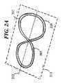
図2A~Cは、本開示のいくつかの実施形態による捻れた8の字コイル250を製造するためのプロセス200を図示している。図2Aは、第1のループ205および第2のループ210が実質的に同一の平面215上にある真っ直ぐな8の字コイル202を図示している。プロセス200は、実質的に同一の平面215上に留まっている間、1~90度等の任意の量の度だけ長軸212に対して第2のループ210をオフセットさせることによって開始する。例えば、第2のループ210は、所望のオフセット角度(例えば、15、20、30、45)に到達するまで、集束点220について捻られ得る。その間ずっと、第2のループ210の一次平面は、平面215に実質的に平行である。図2Bに示されているように、角度225は、概ね28.4度であり、第2のループ210は、依然として平面215に実質的に平行である。この実施例では、軸204は、第2のループ210の主軸である。 Figures 2A-C illustrate a
次に、ループ210が、その後、軸204について所望の回転度(例えば、2、10、45、90)だけ回転させられる。これは、第2のループ210が捻られ、オフセットされると、捻れた8の字コイル250を生成する。捻れた8の字コイル250は、最初に第2のループ210を軸212について(任意の回転度だけ)回転させ、その後、図2Bに示されているように、回転させられたコイルをオフセットさせることによっても形成され得ることに留意されたい。最終結果は、図2Cに示されているものと同一のコイル250である。
第1のループ(例えば、105、205)は、第2のループ(例えば、110、210)と概ね同一の直径を有し得る。第1のループの直径(Dloop1)は、第2のループの直径(Dloop2)より小さくあり得る。いくつかの実施形態では、第1のループは、第2のループより大きい直径を有し得る(Dloop1>Dloop2)。第1および第2のループは、円形、多角形、または楕円形であり得る。いくつかの実施形態では、第1および第2のループは、楕円形または多角形(例えば、六角形および十角形)等の異なるループ形状を有し得る。例えば、第1のループ(例えば、105、205)は、円形であり得、第2のループ(例えば、110、210)は、多角形であり得る。別の事例では、第1のループ(例えば、105、205)は、楕円形形状を有し得、第2のループ(例えば、110、210)は、六角形形状を有し得る。The first loop (eg, 105, 205) can have approximately the same diameter as the second loop (eg, 110, 210). The diameter of the first loop (Dloop1 ) can be smaller than the diameter of the second loop (D loop2) . In some embodiments, the first loop may have a larger diameter than the second loop (Dloop1 >Dloop2 ). The first and second loops can be circular, polygonal, or elliptical. In some embodiments, the first and second loops can have different loop shapes, such as elliptical or polygonal (eg, hexagonal and decagonal). For example, a first loop (eg, 105, 205) can be circular and a second loop (eg, 110, 210) can be polygonal. In another case, a first loop (eg, 105, 205) may have an elliptical shape and a second loop (eg, 110, 210) may have a hexagonal shape.
第1のループ105および第2のループ110の断面形状は、同一であり得る。代替として、第1のループ105および第2のループ110の断面形状は、異なり得る。例えば、第1のループ105は、円形断面形状を有し得、第2のループ110は、六角形断面形状を有し得る。第1のループ105および第2のループ110のコイル厚み(断面の直径)は、同一であり得る。いくつかの実施形態では、第1のループ105および第2のループ110のコイル厚みは、異なり得る。例えば、第1のループは、第2のループより大きい外径を有し得る。例えば、第1のループは、0.00257”の外径を有し得、第2のループは、0.002”の外径を有し得る。 The cross-sectional shape of the
加えて、捻れた8の字コイル100および250は、2つの異なる部分、すなわち、近位部分および遠位部分を有し得る。近位部分は、20~40cmの全長を有し得、遠位部分は、3~10cmの全長を有し得る。各部分は、複数の捻れた8の字コイルを有し得る。コイル100および250が(例証目的のために)個々に示されているが、コイル100および250は、図11に示されているように、相互に接続されている複数のコイルを有し得る。 Additionally, the twisted figure-eight
再び図1Aを参照すると、いくつかの実施形態では、血管内コイル100および/または250は、端間長140を有し得、端間長140は、軸130と同じ場所に生じ、第1のループ105と第2のループ110との直径の和(Dloop1+Dloop2)に実質的に等しい。コイル100の長さ140は、Dloop1+Dloop2より大きくあり得る。この実施形態では、遷移部分130は、ループ間のあるオフセット距離を有し得る。オフセットは、ループのうちの1つに対する接線方向であり得る。端間長140は、Dloop1+Dloop2未満であり得る。例えば、長さ140は、ループ105と110との直径の和の0.5倍(0.5×(Dloop1+Dloop2))であり得る。長さ140は、ループ105と110との直径の和の2倍(2×(Dloop1+Dloop2))より大きくあり得る。いくつかの実施形態では、長さ140は、0.6×(Dloop1+Dloop2)~1.4×(Dloop1+Dloop2)の範囲であり得る。一実施形態では、長さ140は、0.75×(Dloop1+Dloop2)~1.25×(Dloop1+Dloop2)の範囲であり得る。Referring again to FIG. 1A, in some embodiments,
いくつかの実施形態では、軸130は、湾曲または角度付けもされ得る。曲線は、コイル100の端から端まで漸次的であり得る。代替として、曲線は、遷移部分130から急になり得る。軸130は、ループ105およびループ110の接線が相互に平行または垂直であり得る(0~90度)ような曲線または角度であり得る。いくつかの実施形態では、ループ105およびループ110の接線は、相互に対して45度である。 In some embodiments,
各ループ105または110は、ともに積層された複数のループを有し得る(図10を参照)。積層内の各ループの形状は、実質的に同一であり得る。代替として、積層内の各ループの形状は、異なり得る。例えば、ループ105は、ともに積層された3つのループを有し得る。第1のループは、円形であり得、第2のループは、楕円形であり得、第3のループは、多角形であり得る。ループ150は、ともに積層された4つのループを有し得、1つまたは複数のループは、図1Aおよび図2Cに示されているように、主平面(例えば、平面115)からのあるオフセットにおいて位置し得る。 Each
いくつかの実施形態では、遷移または変曲部分130は、ループ部分145および147が相互に最も近いエリアであるくびれエリアを含む。くびれ間隙150は、ループ部分145と147との間の距離である。いくつかの実施形態では、間隙150のサイズは、0(接触または重複)~ループ105またはループ110の直径の半分の範囲であり得る。間隙150のサイズは、ループ105のワイヤコイルの直径と実質的に同一であり得る。いくつかの実施形態では、間隙150は、0.1×(Dloop1)~0.8×(Dloop1)の範囲をとり得る。例えば、間隙150は、Dloop1またはDloop2の0.3倍であり得る。間隙150は、0.1×(Dloop2)~0.8×(Dloop2)の範囲でもあり得る。記されているように、Dloop1は、Dloop2と異なり得る。In some embodiments, transition or
いくつかの実施形態では、ループ105は、ループ105およびループ110が初めに平行である(同一平面上にある)状態において、マンドレル上に形成され得る。その後、マンドレルは、ループ105および110に対する角度を調節するために、熱成形に先立って回転させられ得る。マンドレルは、ループ105および110に対する角度が5~175度で調節され得るように、回転可能に構成されている。例えば、マンドレルは、熱成形に先立って30~90度だけ回転させられ得る。血管内コイル100は、ニチノール等の形状保持金属合金で作製され得る。他の好適な生体適合性金属および/または金属合金も、コイル100を製造するために使用され得る(例えば、ステンレス鋼、白金)。 In some embodiments,
図3は、本開示のいくつかの実施形態によるコイル300の上面図である。コイル300は、図1A~1Bおよび2A~2Cに関して記載されているような、コイル100および250の1つまたは複数の特徴および属性を有し得る。コイル300は、底部ループ310が長軸330について概ね90度だけ回転させられた捻れた8の字コイルである。ループ310が90度だけ回転させられている場合が示されているが、15、20、25、35、40、および45度等の任意の所望の度だけ回転させられ得る。 FIG. 3 is a top view of
示されているように、コイル300は、上側ループ305と、底部ループ310とを含む。ループ305は、実質的に平面315上に配置され得、ループ310は、実質的に平面330上に配置され得る。ループ310は、平面330の上方および下方にうねる起伏トレースパターンを有し得る。例えば、任意の開始点からループ310の円周全体をトレースするとき、(ループ310の円周に追従するように)トレースされる経路は、ループ全体がトレースされるときにいくつかの場所で平面330を突き抜ける。いくつかの実施形態では、ループ310は、左で少なくとも2回、および右で少なくとも2回、平面235を突き抜ける。例えば、ループ310は、3つの異なる場所320、322、および324で平面235を突き抜け得る。いくつかの実施形態では、ループ305および/または210は、円形形状または六角形もしくは十角形等の多角形形状の全体を有し得る。図3からは明白でないが、ループ305は、示されているように円形形状から外にトレースすると平面315の上方および下方に起伏することもあり得る。代替として、ループ305は、実質的に平坦であり得る。 As shown,
図4は、本開示のいくつかの実施形態によるコイル100を図示している。コイル100は、ループのうちの1つまたは複数に1つまたは複数の応力点(角または急な遷移)を有し得る。例えば、ループ310は、コイルの中に誘発された応力点415、420、および425を有し得る。これは、熱成形プロセス中に比較的鋭い縁を伴うマンドレルを使用し、それに接するように応力点が巻着されることによってなされ得る。応力点の各々は、ループ305または310の半径の0.001~0.5である屈曲半径(r)を有し得る。例えば、応力点のうちの1つは、0.1×rまたは0.2×rの屈曲半径を有し得る。 FIG. 4 illustrates
図5は、本開示のいくつかの実施形態による閉ループアーキテクチャを伴うコイル100を図示している。コイル100は、ループ105の一部がループ110の一部に接触し、ループ105および110を閉鎖する遷移または変曲エリア130を含む。加えて、コイル100は、時計回り(CW)および反時計回り(CCW)経路を有し得る。例えば、ループ105は、CW経路を有し、ループ110は、CCW経路を有する。コイル100は、図1Aに示されているような、ループが相互に接触しない開ループ設計を有することもある。 FIG. 5 illustrates a
図6は、本開示のいくつかの実施形態によるコイル100を図示している。示されているように、コイル600は、ループ105および110が閉ループである閉ループアーキテクチャを有する。加えて、ループ105および110は、両方のループが時計回り経路を有するように遷移領域130において相互について回転させられている。 FIG. 6 illustrates
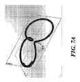
図7Aおよび図7Bは、本開示のいくつかの実施形態による遷移エリアにおいて異なる形状を伴う例示的コイル100を図示している。示されているように、遷移エリア715は、遷移エリア720より緊密であり、遷移エリア720より小さい。 7A and 7B illustrate
上記に記載の骨組コイルの各々は、繰り返しループを1つまたは複数の平面(例えば、平面115または平面120)上に有し得る。いくつかの実施形態では、異なる平面対(例えば、平面2/平面3、平面3/平面4)を使用して、開示される関係を後続ループ対上に適用することによって意図されるコイルの長さを生成し、意図されるコイルの長さは、1cm~80cmであり得る。コイル形状は、コイルの全長を通して閉鎖/開放、交差/非交差、およびCW/CCW方略の組み合わせを活用し得る。コイル250および300は、図1A、図1B、図4、図5、図6、図7、および図8に記載されているような、コイル100の1つまたは複数の特徴および属性でもあり得ることに留意されたい。 Each of the skeletal coils described above may have repeating loops on one or more planes (eg,
図8は、上記に記載されたようなコイル100、250、および300の1つまたは複数の特徴および属性を伴う例示的全長血管内コイル800を図示している。コイル800は、上側部分805に4つのループを含み、下側部分810に3つのループを含む。しかしながら、コイル800は、上側および下側部分805、810の各々に任意の数のループを有するように製造され得る。示されているように、下側部分810におけるループは、所望の回転度において長軸815について回転させられ、所望の回転度は、45度であり得る。 FIG. 8 illustrates an exemplary full-length
図9は、コイル100、250、および300の1つまたは複数の特徴および属性を伴う例示的全長血管内コイル900を図示している。コイル900は、第1の部分905と、第2の部分910とを含む。第1の部分905は、2つまたはそれより多くのループ915、920を含む。2つまたはそれより多くのループ915、920は、同一のループ直径を有し得る。いくつかの実施形態では、2つまたはそれより多くのループ915、920のうちの1つは、第1の部分905の他のループより小さい直径を有する。同様に、第2の部分910は、2つまたはそれより多くのループ925、930を含む。2つまたはそれより多くのループ925、930は、同一のまたは異なるループ直径を有し得る。加えて、第2の部分910は、第1の部分905のコイルワイヤと異なる属性(例えば、外径、剛性、断面形状、線維毛)を伴うコイルワイヤから成り得る。いくつかの実施形態では、第2の部分910の2つまたはそれより多くの最終ループは、限定ではないが、より小さい直径、異なる断面形状、および異なる材料等の異なる属性を伴うコイルワイヤを用いて作製され得る。 FIG. 9 illustrates an exemplary full length
図10A~Hは、本開示のいくつかの実施形態による捻れた8の字コイル(例えば、100、250、300、800、900)を巻回するためのプロセス1000を図示している。図10Aに示されているように、マンドレル1005は、第1のロッド1010と、第2のロッド1015と、マンドレル基部1020とを含む。コイル製造プロセス中、ロッド1010、1015の両方は、マンドレル基部1020に固定され得る。ワイヤ巻着プロセスが完了されると、マンドレル基部1020は、除去され得、ロッド1005、1010がコイル巻着の中心点について相互に対して回転することを可能にし得る(このプロセスは、下記にさらに記載される)。 10A-H illustrate a
プロセス1000は、図10Aから開始し、図10Aでは、コイルワイヤ1030のワイヤ1025の端部部分が、柱部1035の周囲に固定されている。端部部分1005が柱部1035に固定されると、コイルワイヤ1030は、後続ループより小さいループ直径を伴う第1のループを生成する溝1040(随意)の中に押し込まれる。溝1040は、溝の底部がロッド1010の外面と同一レベルまでゆっくりと上昇する遷移エリア(示されていない)を含み得る。コイルワイヤ1030の遠位端(示されていない)は、架張機構または重りに固定されている。これは、張力を保ち、ロッド1010または1015の周囲で緊密巻着を生成するために役立つ。
図10Bでは、マンドレル1005は、(親指が左を指した状態における右手の法則によって定義されるように、)ページの中に入るように180度だけ回転させられる。この行為は、示されているようにコイル130を引き上げ、コイルワイヤ130を吊架したままにする。図10Cでは、コイルワイヤ1030は、ロッド1010と1015との間に設置されている。次に、図10Dでは、マンドレル105は、360度だけページの中に回転させられ、コイルワイヤ1030は、ロッド1010と1015との間に再び設置される。次に、図10Eでは、マンドレル1005は、ページの外に出るように回転させられ(右親指は右を指している)、コイルワイヤ1030は、ロッド1010と1015との間に設置される。図10Fにおいて次の巻着を生成するために、マンドレル1005は、(ページの中への)対向方向に回転させられ、再び、コイルワイヤ1030は、マンドレル1005の次の回転の前にロッド1010と1015との間に設置される。図10Eおよび10Fに示されている手順は、所望の数のループが生成されるまで繰り返される(例えば、マンドレルは、1回おきに対向方向に回転させられ、コイルワイヤは、各回転後、ロッド1010と1015との間に通される)。コイル巻着が緩く離間されている場合が示されているが、実践例では、コイル巻着は、緊密に巻着され、各コイル巻着間に殆どまたは全く余地がない状態において相互に隣接している。 In FIG. 10B,
図10Gは、多数の所望のループがロッド1010および1015の周囲に巻着されているコイルを図示している。所望の数のループが生成されると、マンドレル基部1020は、除去され得、ロッド1010および1015の周囲に巻着される全てのループの概ね中心である中心点1050について、ロッド1010および1015が相互に対して回転することを可能にし得る。図10Hは、中心点1050について回転させられたロッド1010および1015を示している。回転角度は、設計仕様に応じて変動し得る。しかしながら、回転角度は、1~179度の任意の角度であり得る。いくつかの実施形態では、回転角度は、45度である。回転設定および係止機構(示されていない)が、回転角度を設定するために使用され得、ロッド1010および1015を所望の回転角度に固定するためにも使用され得る。マンドレル全体ならびに回転設定および係止機構アセンブリは、その後、熱硬化手順のために炉の中に設置される。熱硬化プロセスは、コイル100の二次構成(例えば、最小エネルギー状態)の形状をロッドを伴わない図10Hに示されているものと同一の形状に硬化させる。 FIG. 10G illustrates a coil with a number of desired loops wrapped around
熱硬化手順に関して、炉は、摂氏650~750度に設定され得、焼成時間は、20~40分であり得る。いくつかの実施形態では、焼成時間は、30分であり、炉の温度は、摂氏700度に設定される。代替として、コイル100は、摂氏735度で熱処理され得る。図10A~10Hはマンドレル1005のロッド1010および1015の周囲に8の字パターンを生成するために使用される具体的な配索パターンを記載しているが、複数の8の字パターンがロッド1010および1015の周囲に生成される限り、他の配索パターンも、可能であり、検討される。例えば、コイルワイヤ1030が複数の8の字パターンを生成するためにロッド1010および1015の周囲で操作されている間、マンドレル1005は、静止し得る。これが行われると、ロッドのうちの一方は、8の字パターンのうちの1つの長軸に実質的に沿ってあり得る回転点について、他方のロッドに対して回転させられ得る。 For heat curing procedures, the oven can be set at 650-750 degrees Celsius and the baking time can be 20-40 minutes. In some embodiments, the firing time is 30 minutes and the furnace temperature is set at 700 degrees Celsius. Alternatively, the
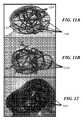
図11A~Bは、従来のコイルが不規則的形状の動脈瘤を充填する方法を図示している。図11Aでは、従来のコイルは、多くの開放空間1105を残す。同様に、図11Bでは、別の従来のコイルは、さらに多くの、かつより大きい開放空間を動脈瘤内に残す。ここで、図11Aおよび図11Bにおけるコイルの両方は、本質的に同一の長さである。図12は、上記に記載されたような捻れた8の字コイル(例えば、100、250、300)が動脈瘤を充填する方法を示している。図11Aおよび図11Bと対照的に、捻れた8の字コイルは、開放空間を動脈瘤内に殆ど残さない。空間1205の数は、図11Aおよび図11Bにおける空間1105および1110の数よりそれぞれはるかに少ない。図12における捻れた8の字コイルのコイル長さは、図11Aおよび図11Bにおけるコイルの長さと同一である。 11A-B illustrate how a conventional coil fills an irregularly shaped aneurysm. 11A, the conventional coil leaves a lot of
いくつかの実施形態では、上記に開示された捻れた8の字コイル(例えば、100、250、300、800、900)は、異なるコイルワイヤ材料を用いて作製された遠位部分を有し得る。遠位部分は、近位部分の端部上に溶接され得、近位部分は、遠位部分の長さより長くあり得る。遠位部分は、近位部分より5~7分の1倍短い長さを有し得る。遠位部分の長さは、長さが2つまたはそれより多くのループを生成するために十分であるように適切に選択され得る。 In some embodiments, the twisted figure-eight coils disclosed above (e.g., 100, 250, 300, 800, 900) can have distal portions made with different coil wire materials. . The distal portion may be welded onto the end of the proximal portion and the proximal portion may be longer than the length of the distal portion. The distal portion may have a length that is five to seven times shorter than the proximal portion. The length of the distal portion can be appropriately selected such that the length is sufficient to create two or more loops.
遠位部分のワイヤは、近位部分のワイヤより小さい外径を有し得る。いくつかの実施形態では、遠位部分のワイヤの外径は、0.002”インチである。熱硬化手順に関して、捻れた8の字コイルの近位部分は、遠位部分上での溶接に先立って熱処理(硬化)され得る。遠位部分が溶接されると、コイルアセンブリ全体(近位部分および遠位部分)は、4~6分間、摂氏70~90度の範囲の温度において再び熱処理され得る。いくつかの実施形態では、コイルアセンブリ全体は、概ね5分間、摂氏80度の温度において再び熱処理され得る。これは、(遠位部分上で溶接されたことによって形成された)遠位ループの直径を20%収縮させることに役立つ。言い換えると、遠位ループの直径は、主ループの80%である。 The wires in the distal portion may have a smaller outer diameter than the wires in the proximal portion. In some embodiments, the outer diameter of the wire in the distal portion is 0.002″ inch. It may be heat treated (hardened) prior Once the distal portion is welded, the entire coil assembly (proximal and distal portions) is heat treated again for 4-6 minutes at a temperature in the range of 70-90 degrees Celsius. In some embodiments, the entire coil assembly can be heat treated again at a temperature of 80 degrees Celsius for approximately 5 minutes, which is the distal loop (formed by being welded on the distal portion). 20% of the diameter of the .In other words, the diameter of the distal loop is 80% of the main loop.
コイル900は、2つの3D空間にわたって50/50分布を有するように構成され得る。このように、二葉性動脈瘤は、骨組コイル800によって効果的に充填され得る。
本発明に開示される複雑な形状は、患者動脈の中へのループ突出のリスクを最小限にしながら球状および/または非球状(例えば、楕円形、多葉性)動脈瘤を効果的に治療する能力を提供することを意図されている。識別された固有の属性、パラメータ、および関係は、達成可能充塞密度、送達摩擦、コイル分布均一性、頸部被覆、区画化を最小限にする能力、および長期安定性等のエリアにおいて、既存のコイル設計と比較して改善された性能を実現させる固有の可能性を提示する。下記の表1は、実験データから導き出された重要因子(例えば、属性、パラメータ、および/または関係)を利用することの性能利点を列挙している。
本明細書における「一実施形態」または「ある実施形態」への言及は、実施形態に関連して記載された特定の特徴、構造、または特性が本発明の少なくとも1つの実施形態に含まれることを意味する。本明細書内の種々の場所での語句「一実施形態では」の表出は、必ずしも全て同一の実施形態を指しているわけではない。 Any reference herein to "one embodiment" or "an embodiment" means that the particular feature, structure, or property described in connection with the embodiment is included in at least one embodiment of the invention. means The appearances of the phrase "in one embodiment" in various places in this specification are not necessarily all referring to the same embodiment.
以下の詳細な説明のいくつかの部分は、コンピュータメモリ内のデータビットに対する動作のアルゴリズムおよび象徴的表現の観点から提示される。これらのアルゴリズム的説明および表現は、データ処理分野の当業者がその研究内容を他の当業者に最も効果的に伝えるために使用される方法である。ここで、アルゴリズムは、一般に、所望の結果につながるステップの自己整合シーケンスであると見なされる。ステップは、物理量の物理的操作を必要とするものである。必ずしもではないが、通常、これらの数量は、貯蔵されること、伝達されること、組み合わせられること、比較されること、または別様に操作されることが可能な電気もしくは磁気信号の形態をとる。主に一般的な使用の理由により、ビット、値、要素、シンボル、文字、項、数字、または同等物としてこれらの信号を参照することが時として便宜的であることが、明らかになっている。 Some portions of the detailed descriptions that follow are presented in terms of algorithms and symbolic representations of operations on data bits within a computer memory. These algorithmic descriptions and representations are the means used by those skilled in the data processing arts to most effectively convey the substance of their work to others skilled in the art. Here, algorithms are generally viewed as self-aligning sequences of steps leading to a desired result. The steps are those requiring physical manipulations of physical quantities. Usually, though not necessarily, these quantities take the form of electrical or magnetic signals capable of being stored, transferred, combined, compared, or otherwise manipulated. . It has proven convenient at times, principally for reasons of common usage, to refer to these signals as bits, values, elements, symbols, characters, terms, numbers, or the like. .
図および以下の説明は、例証のみによってある実施形態を説明している。当業者は、以下の説明から、本明細書に図示される構造および方法の代替実施形態が本明細書に説明される原理から逸脱することなく採用され得ることを容易に認識する。ここで、参照が、いくつかの実施形態に対して詳細になされ、その実施例が、付属の図に図示されている。実践可能である場合は常に、類似または同様の参照番号が図において使用され、類似または同様の機能性を示し得ることに留意されたい。 The figures and the following description describe certain embodiments by way of illustration only. Those skilled in the art will readily recognize from the following description that alternative embodiments of the structures and methods illustrated herein can be employed without departing from the principles described herein. Reference will now be made in detail to several embodiments, examples of which are illustrated in the accompanying figures. Note that wherever practicable, similar or similar reference numbers may be used in the figures to indicate similar or similar functionality.
本発明の実施形態の前述の説明は、例証および説明目的のために提示されている。包括的であること、または本発明を開示される精密な形態に限定することは、意図されていない。多くの修正および変形例が、上記の教示に照らして可能である。本発明の範囲はこの詳細な説明によってではなく、むしろ、本出願の特許請求の範囲によって限定されることが、意図されている。当業者に理解されるように、本発明は、その精神または本質的な特性から逸脱することなく他の具体的な形態で具現化され得る。同様に、モジュール、ルーチン、特徴、属性、方法論、および他の側面の特定の命名および分割は、必須でも顕著でもなく、本発明またはその特徴を実装した機構は、異なる名称、分割、および/または形式を有し得る。 The foregoing description of embodiments of the invention has been presented for purposes of illustration and description. It is not intended to be exhaustive or to limit the invention to the precise forms disclosed. Many modifications and variations are possible in light of the above teaching. It is intended that the scope of the invention be limited not by this detailed description, but rather by the claims of this application. As will be understood by those skilled in the art, the invention may be embodied in other specific forms without departing from the spirit or essential characteristics thereof. Similarly, specific naming and division of modules, routines, features, attributes, methodologies, and other aspects are not required or prominent, and mechanisms implementing the invention or its features may be named, divided, and/or can have the form
Claims (23)
Translated fromJapanese第1のループと、
第2のループと、
前記第1のループの一部が前記第2のループの一部に遷移する変曲領域と
を備え、前記第2のループは、第1の軸について第1の回転度だけ回転させられ、前記第1の軸は、前記第1のループの主軸に実質的に平行である、血管内コイル。An intravascular coil,
a first loop;
a second loop;
an inflection region where a portion of the first loop transitions to a portion of the second loop, wherein the second loop is rotated a first degree of rotation about a first axis; The intravascular coil, wherein the first axis is substantially parallel to the major axis of said first loop.
第1の主軸を有する第1のループと、
前記第1のループに接続されている第2のループであって、第2の主軸を有する第2のループと
を備え、前記第1および第2の主軸は、相互に実質的に平行であり、前記第2のループは、前記第2の主軸について回転させられ、前記第1および第2のループは、8の字形状を形成する、塞栓コイル。an embolic coil,
a first loop having a first principal axis;
a second loop connected to the first loop, the second loop having a second major axis, the first and second major axes being substantially parallel to each other; , the second loop is rotated about the second principal axis and the first and second loops form a figure eight shape.
コイルワイヤの第1の端部をマンドレルの第1のロッドに固定することであって、前記マンドレルは、前記第1のロッドおよび第2のロッドを備える、ことと、
前記ワイヤを前記第1および第2のロッドの周囲に配索し、複数の8の字ワイヤパターンを前記第1および第2のロッド上に生成することと、
前記第1および第2のロッドのうちの1つを回転点について第1の回転度だけ回転させることであって、前記回転点は、前記複数の8の字ワイヤパターンのうちの1つの長軸上に実質的に位置する、ことと、
前記第1の回転度だけ前記マンドレル内で回転させられながら、前記複数の8の字ワイヤパターンを熱硬化させることと、
を含む、方法。A method of manufacturing an intravascular coil, comprising:
securing a first end of a coil wire to a first rod of a mandrel, said mandrel comprising said first rod and a second rod;
routing the wires around the first and second rods to create a plurality of figure-eight wire patterns on the first and second rods;
rotating one of said first and second rods a first degree of rotation about a point of rotation, said point of rotation being the longitudinal axis of one of said plurality of figure eight wire patterns; located substantially on the
heat setting the plurality of figure eight wire patterns while being rotated within the mandrel by the first degree of rotation;
A method, including
Applications Claiming Priority (3)
| Application Number | Priority Date | Filing Date | Title |
|---|---|---|---|
| US201962900012P | 2019-09-13 | 2019-09-13 | |
| US62/900,012 | 2019-09-13 | ||
| PCT/US2020/050599WO2021051030A1 (en) | 2019-09-13 | 2020-09-13 | Endovascular coil and method for making the same |
Publications (3)
| Publication Number | Publication Date |
|---|---|
| JP2022547578Atrue JP2022547578A (en) | 2022-11-14 |
| JPWO2021051030A5 JPWO2021051030A5 (en) | 2023-11-14 |
| JP7751566B2 JP7751566B2 (en) | 2025-10-08 |
Family
ID=74866755
Family Applications (1)
| Application Number | Title | Priority Date | Filing Date |
|---|---|---|---|
| JP2022516061AActiveJP7751566B2 (en) | 2019-09-13 | 2020-09-13 | Intravascular coil and method for making same |
Country Status (5)
| Country | Link |
|---|---|
| US (2) | US12150649B2 (en) |
| EP (1) | EP4027900A4 (en) |
| JP (1) | JP7751566B2 (en) |
| CN (1) | CN114615940A (en) |
| WO (1) | WO2021051030A1 (en) |
Citations (12)
| Publication number | Priority date | Publication date | Assignee | Title |
|---|---|---|---|---|
| JPH08336537A (en)* | 1995-06-06 | 1996-12-24 | Target Therapeutics Inc | Three-dimensional packing type blood vessel plugging coil |
| US20020107534A1 (en)* | 2000-09-26 | 2002-08-08 | Dean Schaefer | Microcoil vaso-occlusive device with multi-axis secondary configuration |
| JP2006500108A (en)* | 2002-09-19 | 2006-01-05 | マイクロ ベンション インコーポレイテッド | Microcoil vascular occlusion device with multi-axis secondary shape |
| US20060241686A1 (en)* | 1995-04-20 | 2006-10-26 | Ferrera David A | Three dimensional, low friction vasoocclusive coil, and method of manufacture |
| JP2009516547A (en)* | 2005-11-17 | 2009-04-23 | マイクロベンション インコーポレイテッド | 3D complex coil |
| US20130184658A1 (en)* | 2012-01-13 | 2013-07-18 | W. L. Gore & Associates, Inc. | Occlusion devices and methods of their manufacture and use |
| JP2014083239A (en)* | 2012-10-24 | 2014-05-12 | Kaneka Corp | Secondary coil for intracorporal indwelling and method of manufacturing the same |
| JP2015029864A (en)* | 2013-08-07 | 2015-02-16 | 株式会社カネカ | Mold for manufacturing in-vivo indwelling member, in-vivo indwelling member manufacturing apparatus having the mold and method for manufacturing in-vivo indwelling member using the mold |
| US20150182227A1 (en)* | 2013-12-27 | 2015-07-02 | Blockade Medical, LLC | Coil system |
| US20170105738A1 (en)* | 2014-05-19 | 2017-04-20 | Kaneka Corporation | In vivo indwelling member and method for producing same |
| US20180263633A1 (en)* | 2015-11-19 | 2018-09-20 | Kaneka Corporation | In vivo indwelling member, and in vivo indwelling member placement device provided with said in vivo indwelling member |
| JP2019516425A (en)* | 2016-05-13 | 2019-06-20 | コヴィディエン リミテッド パートナーシップ | Aneurysm treatment coil |
Family Cites Families (11)
| Publication number | Priority date | Publication date | Assignee | Title |
|---|---|---|---|---|
| US6638291B1 (en) | 1995-04-20 | 2003-10-28 | Micrus Corporation | Three dimensional, low friction vasoocclusive coil, and method of manufacture |
| US5645558A (en)* | 1995-04-20 | 1997-07-08 | Medical University Of South Carolina | Anatomically shaped vasoocclusive device and method of making the same |
| US5766160A (en) | 1995-06-06 | 1998-06-16 | Target Therapeutics, Inc. | Variable stiffness coils |
| US6860893B2 (en) | 1997-08-29 | 2005-03-01 | Boston Scientific Scimed, Inc. | Stable coil designs |
| US7485123B2 (en) | 2004-03-01 | 2009-02-03 | Boston Scientific Scimed, Inc. | Complex vaso-occlusive coils |
| US7488332B2 (en)* | 2004-03-01 | 2009-02-10 | Boston Scientific Scimed, Inc. | Vaso-occlusive coils with non-overlapping sections |
| JP6157453B2 (en) | 2011-05-11 | 2017-07-05 | マイクロベンション インコーポレイテッド | Coil packing |
| CN108186074A (en)* | 2014-02-27 | 2018-06-22 | 因库麦迪斯有限公司 | For treating the framework microcoils of vascular diseases |
| US10307168B2 (en) | 2015-08-07 | 2019-06-04 | Terumo Corporation | Complex coil and manufacturing techniques |
| WO2017117284A1 (en)* | 2015-12-30 | 2017-07-06 | Stryker Corporation | Embolic devices and methods of manufacturing same |
| JP6418613B2 (en) | 2016-05-31 | 2018-11-07 | 国立大学法人信州大学 | Embolic coil |
- 2020
- 2020-09-13JPJP2022516061Apatent/JP7751566B2/enactiveActive
- 2020-09-13USUS17/019,292patent/US12150649B2/enactiveActive
- 2020-09-13EPEP20863096.2Apatent/EP4027900A4/enactivePending
- 2020-09-13CNCN202080078071.7Apatent/CN114615940A/enactivePending
- 2020-09-13WOPCT/US2020/050599patent/WO2021051030A1/ennot_activeCeased
- 2024
- 2024-09-19USUS18/890,496patent/US20250009360A1/enactivePending
Patent Citations (15)
| Publication number | Priority date | Publication date | Assignee | Title |
|---|---|---|---|---|
| US20060241686A1 (en)* | 1995-04-20 | 2006-10-26 | Ferrera David A | Three dimensional, low friction vasoocclusive coil, and method of manufacture |
| JPH08336537A (en)* | 1995-06-06 | 1996-12-24 | Target Therapeutics Inc | Three-dimensional packing type blood vessel plugging coil |
| US20020107534A1 (en)* | 2000-09-26 | 2002-08-08 | Dean Schaefer | Microcoil vaso-occlusive device with multi-axis secondary configuration |
| US20060184196A1 (en)* | 2000-09-26 | 2006-08-17 | Microvention, Inc. | Microcoil vaso-occlusive device with multi-axis secondary configuration |
| JP2005514978A (en)* | 2002-01-11 | 2005-05-26 | マイクロ ベンション インコーポレイテッド | Microcoil type vascular embolization device having secondary form with multiple axes |
| JP2006500108A (en)* | 2002-09-19 | 2006-01-05 | マイクロ ベンション インコーポレイテッド | Microcoil vascular occlusion device with multi-axis secondary shape |
| JP2009516547A (en)* | 2005-11-17 | 2009-04-23 | マイクロベンション インコーポレイテッド | 3D complex coil |
| US20120041464A1 (en)* | 2005-11-17 | 2012-02-16 | Richard Monetti | Three-Dimensional Complex Coil |
| US20130184658A1 (en)* | 2012-01-13 | 2013-07-18 | W. L. Gore & Associates, Inc. | Occlusion devices and methods of their manufacture and use |
| JP2014083239A (en)* | 2012-10-24 | 2014-05-12 | Kaneka Corp | Secondary coil for intracorporal indwelling and method of manufacturing the same |
| JP2015029864A (en)* | 2013-08-07 | 2015-02-16 | 株式会社カネカ | Mold for manufacturing in-vivo indwelling member, in-vivo indwelling member manufacturing apparatus having the mold and method for manufacturing in-vivo indwelling member using the mold |
| US20150182227A1 (en)* | 2013-12-27 | 2015-07-02 | Blockade Medical, LLC | Coil system |
| US20170105738A1 (en)* | 2014-05-19 | 2017-04-20 | Kaneka Corporation | In vivo indwelling member and method for producing same |
| US20180263633A1 (en)* | 2015-11-19 | 2018-09-20 | Kaneka Corporation | In vivo indwelling member, and in vivo indwelling member placement device provided with said in vivo indwelling member |
| JP2019516425A (en)* | 2016-05-13 | 2019-06-20 | コヴィディエン リミテッド パートナーシップ | Aneurysm treatment coil |
Also Published As
| Publication number | Publication date |
|---|---|
| CN114615940A (en) | 2022-06-10 |
| US20250009360A1 (en) | 2025-01-09 |
| JP7751566B2 (en) | 2025-10-08 |
| EP4027900A4 (en) | 2023-09-13 |
| US20210085334A1 (en) | 2021-03-25 |
| EP4027900A1 (en) | 2022-07-20 |
| WO2021051030A1 (en) | 2021-03-18 |
| US12150649B2 (en) | 2024-11-26 |
Similar Documents
| Publication | Publication Date | Title |
|---|---|---|
| CN101394955B (en) | Three-dimensional compound coil | |
| CN102302390B (en) | Flexible stent | |
| US8210084B2 (en) | Stent and method for manufacturing the same | |
| JP6566961B2 (en) | Emboli frame microcoil | |
| JP2007525304A (en) | Compound vaso-occlusive coil | |
| JP2007525307A (en) | Vascular occlusion coil with non-overlapping portion | |
| KR101320480B1 (en) | Flexible stent | |
| JP2009516547A5 (en) | ||
| KR20210073548A (en) | Embolization device and its spring coil | |
| US11666341B2 (en) | Embolic coils | |
| JP2019516425A (en) | Aneurysm treatment coil | |
| Zheng et al. | Mechanical characterization of braided self-expanding stents: impact of design parameters | |
| KR102352526B1 (en) | stent | |
| KR102428729B1 (en) | Stent and method of manufacturing the stent | |
| JP2022547578A (en) | Intravascular coil and method of making same | |
| HK40078763A (en) | Endovascular coil and method for making the same | |
| US20150297238A1 (en) | Geometric coil | |
| JP2024009069A (en) | Stents with shaped wires | |
| JP6487200B2 (en) | Primary shape body for in-vivo indwelling member, manufacturing method thereof, and mandrel | |
| US20220273473A1 (en) | Stent device having looped interlocking regions and non-looped interlocking regions | |
| JPWO2021051030A5 (en) | ||
| WO2024154279A1 (en) | Stent |
Legal Events
| Date | Code | Title | Description |
|---|---|---|---|
| RD02 | Notification of acceptance of power of attorney | Free format text:JAPANESE INTERMEDIATE CODE: A7422 Effective date:20230320 | |
| RD04 | Notification of resignation of power of attorney | Free format text:JAPANESE INTERMEDIATE CODE: A7424 Effective date:20230404 | |
| A521 | Request for written amendment filed | Free format text:JAPANESE INTERMEDIATE CODE: A523 Effective date:20230913 | |
| A621 | Written request for application examination | Free format text:JAPANESE INTERMEDIATE CODE: A621 Effective date:20230913 | |
| A521 | Request for written amendment filed | Free format text:JAPANESE INTERMEDIATE CODE: A523 Effective date:20231106 | |
| A131 | Notification of reasons for refusal | Free format text:JAPANESE INTERMEDIATE CODE: A131 Effective date:20240328 | |
| A977 | Report on retrieval | Free format text:JAPANESE INTERMEDIATE CODE: A971007 Effective date:20240329 | |
| A601 | Written request for extension of time | Free format text:JAPANESE INTERMEDIATE CODE: A601 Effective date:20240626 | |
| A521 | Request for written amendment filed | Free format text:JAPANESE INTERMEDIATE CODE: A523 Effective date:20240927 | |
| RD02 | Notification of acceptance of power of attorney | Free format text:JAPANESE INTERMEDIATE CODE: A7422 Effective date:20240927 | |
| RD04 | Notification of resignation of power of attorney | Free format text:JAPANESE INTERMEDIATE CODE: A7424 Effective date:20240927 | |
| A521 | Request for written amendment filed | Free format text:JAPANESE INTERMEDIATE CODE: A523 Effective date:20241128 | |
| A131 | Notification of reasons for refusal | Free format text:JAPANESE INTERMEDIATE CODE: A131 Effective date:20250106 | |
| A601 | Written request for extension of time | Free format text:JAPANESE INTERMEDIATE CODE: A601 Effective date:20250404 | |
| A601 | Written request for extension of time | Free format text:JAPANESE INTERMEDIATE CODE: A601 Effective date:20250606 | |
| A521 | Request for written amendment filed | Free format text:JAPANESE INTERMEDIATE CODE: A523 Effective date:20250702 | |
| TRDD | Decision of grant or rejection written | ||
| A01 | Written decision to grant a patent or to grant a registration (utility model) | Free format text:JAPANESE INTERMEDIATE CODE: A01 Effective date:20250828 | |
| A61 | First payment of annual fees (during grant procedure) | Free format text:JAPANESE INTERMEDIATE CODE: A61 Effective date:20250926 |