JP2022544553A - Axial Motion Drives, Systems, and Methods for Robotic Medical Systems - Google Patents
Axial Motion Drives, Systems, and Methods for Robotic Medical SystemsDownload PDFInfo
- Publication number
- JP2022544553A JP2022544553AJP2022509084AJP2022509084AJP2022544553AJP 2022544553 AJP2022544553 AJP 2022544553AJP 2022509084 AJP2022509084 AJP 2022509084AJP 2022509084 AJP2022509084 AJP 2022509084AJP 2022544553 AJP2022544553 AJP 2022544553A
- Authority
- JP
- Japan
- Prior art keywords
- drive
- shaft
- roller
- instrument
- robotic
- Prior art date
- Legal status (The legal status is an assumption and is not a legal conclusion. Google has not performed a legal analysis and makes no representation as to the accuracy of the status listed.)
- Granted
Links
Images


Classifications
- A—HUMAN NECESSITIES
- A61—MEDICAL OR VETERINARY SCIENCE; HYGIENE
- A61B—DIAGNOSIS; SURGERY; IDENTIFICATION
- A61B34/00—Computer-aided surgery; Manipulators or robots specially adapted for use in surgery
- A61B34/30—Surgical robots
- A—HUMAN NECESSITIES
- A61—MEDICAL OR VETERINARY SCIENCE; HYGIENE
- A61B—DIAGNOSIS; SURGERY; IDENTIFICATION
- A61B34/00—Computer-aided surgery; Manipulators or robots specially adapted for use in surgery
- A61B34/20—Surgical navigation systems; Devices for tracking or guiding surgical instruments, e.g. for frameless stereotaxis
- A—HUMAN NECESSITIES
- A61—MEDICAL OR VETERINARY SCIENCE; HYGIENE
- A61B—DIAGNOSIS; SURGERY; IDENTIFICATION
- A61B34/00—Computer-aided surgery; Manipulators or robots specially adapted for use in surgery
- A61B34/30—Surgical robots
- A61B34/37—Leader-follower robots
- A—HUMAN NECESSITIES
- A61—MEDICAL OR VETERINARY SCIENCE; HYGIENE
- A61G—TRANSPORT, PERSONAL CONVEYANCES, OR ACCOMMODATION SPECIALLY ADAPTED FOR PATIENTS OR DISABLED PERSONS; OPERATING TABLES OR CHAIRS; CHAIRS FOR DENTISTRY; FUNERAL DEVICES
- A61G13/00—Operating tables; Auxiliary appliances therefor
- A61G13/02—Adjustable operating tables; Controls therefor
- A61G13/04—Adjustable operating tables; Controls therefor tiltable around transverse or longitudinal axis
- B—PERFORMING OPERATIONS; TRANSPORTING
- B25—HAND TOOLS; PORTABLE POWER-DRIVEN TOOLS; MANIPULATORS
- B25J—MANIPULATORS; CHAMBERS PROVIDED WITH MANIPULATION DEVICES
- B25J9/00—Programme-controlled manipulators
- B25J9/0084—Programme-controlled manipulators comprising a plurality of manipulators
- B25J9/0087—Dual arms
- B—PERFORMING OPERATIONS; TRANSPORTING
- B25—HAND TOOLS; PORTABLE POWER-DRIVEN TOOLS; MANIPULATORS
- B25J—MANIPULATORS; CHAMBERS PROVIDED WITH MANIPULATION DEVICES
- B25J9/00—Programme-controlled manipulators
- B25J9/02—Programme-controlled manipulators characterised by movement of the arms, e.g. cartesian coordinate type
- B—PERFORMING OPERATIONS; TRANSPORTING
- B25—HAND TOOLS; PORTABLE POWER-DRIVEN TOOLS; MANIPULATORS
- B25J—MANIPULATORS; CHAMBERS PROVIDED WITH MANIPULATION DEVICES
- B25J9/00—Programme-controlled manipulators
- B25J9/10—Programme-controlled manipulators characterised by positioning means for manipulator elements
- B25J9/102—Gears specially adapted therefor, e.g. reduction gears
- B25J9/1035—Pinion and fixed rack drivers, e.g. for rotating an upper arm support on the robot base
- B—PERFORMING OPERATIONS; TRANSPORTING
- B25—HAND TOOLS; PORTABLE POWER-DRIVEN TOOLS; MANIPULATORS
- B25J—MANIPULATORS; CHAMBERS PROVIDED WITH MANIPULATION DEVICES
- B25J9/00—Programme-controlled manipulators
- B25J9/16—Programme controls
- B25J9/1615—Programme controls characterised by special kind of manipulator, e.g. planar, scara, gantry, cantilever, space, closed chain, passive/active joints and tendon driven manipulators
- B25J9/1623—Parallel manipulator, Stewart platform, links are attached to a common base and to a common platform, plate which is moved parallel to the base
- B—PERFORMING OPERATIONS; TRANSPORTING
- B25—HAND TOOLS; PORTABLE POWER-DRIVEN TOOLS; MANIPULATORS
- B25J—MANIPULATORS; CHAMBERS PROVIDED WITH MANIPULATION DEVICES
- B25J9/00—Programme-controlled manipulators
- B25J9/16—Programme controls
- B25J9/1628—Programme controls characterised by the control loop
- A—HUMAN NECESSITIES
- A61—MEDICAL OR VETERINARY SCIENCE; HYGIENE
- A61B—DIAGNOSIS; SURGERY; IDENTIFICATION
- A61B17/00—Surgical instruments, devices or methods
- A61B2017/00477—Coupling
- A—HUMAN NECESSITIES
- A61—MEDICAL OR VETERINARY SCIENCE; HYGIENE
- A61B—DIAGNOSIS; SURGERY; IDENTIFICATION
- A61B34/00—Computer-aided surgery; Manipulators or robots specially adapted for use in surgery
- A61B34/10—Computer-aided planning, simulation or modelling of surgical operations
- A61B2034/101—Computer-aided simulation of surgical operations
- A61B2034/105—Modelling of the patient, e.g. for ligaments or bones
- A—HUMAN NECESSITIES
- A61—MEDICAL OR VETERINARY SCIENCE; HYGIENE
- A61B—DIAGNOSIS; SURGERY; IDENTIFICATION
- A61B34/00—Computer-aided surgery; Manipulators or robots specially adapted for use in surgery
- A61B34/20—Surgical navigation systems; Devices for tracking or guiding surgical instruments, e.g. for frameless stereotaxis
- A61B2034/2046—Tracking techniques
- A61B2034/2051—Electromagnetic tracking systems
- A—HUMAN NECESSITIES
- A61—MEDICAL OR VETERINARY SCIENCE; HYGIENE
- A61B—DIAGNOSIS; SURGERY; IDENTIFICATION
- A61B34/00—Computer-aided surgery; Manipulators or robots specially adapted for use in surgery
- A61B34/20—Surgical navigation systems; Devices for tracking or guiding surgical instruments, e.g. for frameless stereotaxis
- A61B2034/2046—Tracking techniques
- A61B2034/2059—Mechanical position encoders
- A—HUMAN NECESSITIES
- A61—MEDICAL OR VETERINARY SCIENCE; HYGIENE
- A61B—DIAGNOSIS; SURGERY; IDENTIFICATION
- A61B34/00—Computer-aided surgery; Manipulators or robots specially adapted for use in surgery
- A61B34/20—Surgical navigation systems; Devices for tracking or guiding surgical instruments, e.g. for frameless stereotaxis
- A61B2034/2046—Tracking techniques
- A61B2034/2065—Tracking using image or pattern recognition
- A—HUMAN NECESSITIES
- A61—MEDICAL OR VETERINARY SCIENCE; HYGIENE
- A61B—DIAGNOSIS; SURGERY; IDENTIFICATION
- A61B34/00—Computer-aided surgery; Manipulators or robots specially adapted for use in surgery
- A61B34/30—Surgical robots
- A61B2034/301—Surgical robots for introducing or steering flexible instruments inserted into the body, e.g. catheters or endoscopes
- A—HUMAN NECESSITIES
- A61—MEDICAL OR VETERINARY SCIENCE; HYGIENE
- A61B—DIAGNOSIS; SURGERY; IDENTIFICATION
- A61B34/00—Computer-aided surgery; Manipulators or robots specially adapted for use in surgery
- A61B34/30—Surgical robots
- A61B2034/302—Surgical robots specifically adapted for manipulations within body cavities, e.g. within abdominal or thoracic cavities
- A—HUMAN NECESSITIES
- A61—MEDICAL OR VETERINARY SCIENCE; HYGIENE
- A61B—DIAGNOSIS; SURGERY; IDENTIFICATION
- A61B90/00—Instruments, implements or accessories specially adapted for surgery or diagnosis and not covered by any of the groups A61B1/00 - A61B50/00, e.g. for luxation treatment or for protecting wound edges
- A61B90/06—Measuring instruments not otherwise provided for
- A61B2090/061—Measuring instruments not otherwise provided for for measuring dimensions, e.g. length
- A—HUMAN NECESSITIES
- A61—MEDICAL OR VETERINARY SCIENCE; HYGIENE
- A61B—DIAGNOSIS; SURGERY; IDENTIFICATION
- A61B90/00—Instruments, implements or accessories specially adapted for surgery or diagnosis and not covered by any of the groups A61B1/00 - A61B50/00, e.g. for luxation treatment or for protecting wound edges
- A61B90/36—Image-producing devices or illumination devices not otherwise provided for
- A61B90/37—Surgical systems with images on a monitor during operation
- A61B2090/371—Surgical systems with images on a monitor during operation with simultaneous use of two cameras
- A—HUMAN NECESSITIES
- A61—MEDICAL OR VETERINARY SCIENCE; HYGIENE
- A61B—DIAGNOSIS; SURGERY; IDENTIFICATION
- A61B90/00—Instruments, implements or accessories specially adapted for surgery or diagnosis and not covered by any of the groups A61B1/00 - A61B50/00, e.g. for luxation treatment or for protecting wound edges
- A61B90/36—Image-producing devices or illumination devices not otherwise provided for
- A61B90/37—Surgical systems with images on a monitor during operation
- A61B2090/376—Surgical systems with images on a monitor during operation using X-rays, e.g. fluoroscopy
- A—HUMAN NECESSITIES
- A61—MEDICAL OR VETERINARY SCIENCE; HYGIENE
- A61B—DIAGNOSIS; SURGERY; IDENTIFICATION
- A61B2217/00—General characteristics of surgical instruments
- A61B2217/002—Auxiliary appliance
- A61B2217/005—Auxiliary appliance with suction drainage system
- A—HUMAN NECESSITIES
- A61—MEDICAL OR VETERINARY SCIENCE; HYGIENE
- A61B—DIAGNOSIS; SURGERY; IDENTIFICATION
- A61B2217/00—General characteristics of surgical instruments
- A61B2217/002—Auxiliary appliance
- A61B2217/007—Auxiliary appliance with irrigation system
- A—HUMAN NECESSITIES
- A61—MEDICAL OR VETERINARY SCIENCE; HYGIENE
- A61B—DIAGNOSIS; SURGERY; IDENTIFICATION
- A61B34/00—Computer-aided surgery; Manipulators or robots specially adapted for use in surgery
- A61B34/70—Manipulators specially adapted for use in surgery
- A61B34/71—Manipulators operated by drive cable mechanisms
- A—HUMAN NECESSITIES
- A61—MEDICAL OR VETERINARY SCIENCE; HYGIENE
- A61B—DIAGNOSIS; SURGERY; IDENTIFICATION
- A61B90/00—Instruments, implements or accessories specially adapted for surgery or diagnosis and not covered by any of the groups A61B1/00 - A61B50/00, e.g. for luxation treatment or for protecting wound edges
- A61B90/30—Devices for illuminating a surgical field, the devices having an interrelation with other surgical devices or with a surgical procedure
- G—PHYSICS
- G05—CONTROLLING; REGULATING
- G05B—CONTROL OR REGULATING SYSTEMS IN GENERAL; FUNCTIONAL ELEMENTS OF SUCH SYSTEMS; MONITORING OR TESTING ARRANGEMENTS FOR SUCH SYSTEMS OR ELEMENTS
- G05B2219/00—Program-control systems
- G05B2219/30—Nc systems
- G05B2219/45—Nc applications
- G05B2219/45118—Endoscopic, laparoscopic manipulator
Landscapes
- Engineering & Computer Science (AREA)
- Health & Medical Sciences (AREA)
- Life Sciences & Earth Sciences (AREA)
- Robotics (AREA)
- Surgery (AREA)
- General Health & Medical Sciences (AREA)
- Animal Behavior & Ethology (AREA)
- Veterinary Medicine (AREA)
- Biomedical Technology (AREA)
- Public Health (AREA)
- Nuclear Medicine, Radiotherapy & Molecular Imaging (AREA)
- Molecular Biology (AREA)
- Medical Informatics (AREA)
- Heart & Thoracic Surgery (AREA)
- Mechanical Engineering (AREA)
- Orthopedic Medicine & Surgery (AREA)
- Manipulator (AREA)
Abstract
Translated fromJapaneseDescription
Translated fromJapanese (優先権及び関連出願)
本出願は、米国特許仮出願第62/887,518号(出願日:2019年8月15日)の優先権を主張するものであり、この文書は参照により本明細書に組み込まれる。本出願と共に提出された出願データシートに特定された外国又は国内の優先権主張の対象である全ての出願は、37CFR1.57に基づいて参照によって本明細書に組み込まれる。(Priority and related applications)
This application claims priority to U.S. Provisional Patent Application No. 62/887,518 filed Aug. 15, 2019, which document is incorporated herein by reference. All applications claiming foreign or domestic priority identified in Application Data Sheets filed with this application are hereby incorporated by reference under 37 CFR 1.57.
(発明の分野)
本明細書に開示されているシステム及び方法は、ロボット医療用システムに関し、より詳細には、ロボット医療用システムにおいて医療用器具の細長いシャフトの軸方向運動を駆動する軸方向運動駆動装置並びに関連するシステム及び方法に関する。(Field of Invention)
TECHNICAL FIELD The systems and methods disclosed herein relate to robotic medical systems and, more particularly, to axial motion drives for driving axial motion of elongated shafts of medical instruments in robotic medical systems. Systems and methods.
内視鏡検査などの医療処置では、診断及び/又は治療目的で患者の解剖学的構造の内部にアクセスし可視化を行う場合がある。例えば、消化器科、泌尿器科、及び呼吸器科では、医師による、尿管、胃腸管、及び気道(気管支及び細気管支)などの患者の管腔の検査を可能にする医療処置が行われる。これらの処置の間、内視鏡として知られる細く、可撓性のある管状ツール又は器具を、開口部(自然開口部など)を通して患者に挿入し、その後の診断及び/又は治療を行うために特定された組織部位に向かって前進させる。医療用器具は、解剖学的構造を通じたナビゲーションを容易にするために制御可能かつ関節運動可能であり得る。 Medical procedures such as endoscopy may involve accessing and visualizing the interior of a patient's anatomy for diagnostic and/or therapeutic purposes. For example, gastroenterology, urology, and pulmonology provide medical procedures that allow a physician to examine a patient's lumens, such as the ureters, gastrointestinal tracts, and airways (bronchi and bronchioles). During these procedures, a thin, flexible tubular tool or instrument known as an endoscope is inserted into the patient through an orifice (such as a natural orifice) for subsequent diagnosis and/or treatment. Advance toward the identified tissue site. Medical instruments may be controllable and articulatable to facilitate navigation through the anatomy.
第1の態様では、ロボット医療用システムであって、器具基部と、患者への挿入のために構成された細長いシャフトと、を含む、医療用器具と、第1のロボットアームであって、医療用器具の器具基部が第1のロボットアームに取り付けられており、第1のロボットアームが器具基部を移動させるように関節運動可能である、第1のロボットアームと、第2のロボットアームと、第2のロボットアームに取り付けられており、器具基部に対して遠位である駆動装置であって、駆動装置は、医療用器具の細長いシャフトと係合し、細長いシャフトの軸方向運動を駆動するように構成されている、駆動装置と、プロセッサであって、第1の軸方向運動期間中に、駆動装置によって、医療用器具の細長いシャフトの軸方向運動を、第1のロボットアームの移動速度よりも大きい第1の軸方向運動速度で駆動するように構成された、プロセッサと、を備える、ロボット医療用システム、が開示される。 In a first aspect, a robotic medical system, a medical instrument including an instrument base and an elongated shaft configured for insertion into a patient; a first robotic arm having an instrument base of an instrument attached to the first robotic arm, the first robotic arm being articulatable to move the instrument base; and a second robotic arm; A drive attached to the second robotic arm and distal to the instrument base, the drive engaging the elongated shaft of the medical instrument and driving axial motion of the elongated shaft a drive and a processor, wherein during the first period of axial motion, the drive causes the axial motion of the elongated shaft of the medical instrument to be equal to the speed of movement of the first robotic arm; A robotic medical system is disclosed comprising a processor configured to drive at a first axial motion velocity greater than.
このロボット医療用システムは、以下の特徴のうちの1つ以上を任意の組み合わせで含み得る。(a)第1の軸方向運動期間中に、器具基部と駆動装置との間の医療用器具の細長いシャフトの一部分は、器具基部と駆動装置との間の距離よりも大きい長さを有し、細長いシャフトの一部分がサービスループを形成する、(b)第1の軸方向運動期間中に、サービスループの長さの変化率は、器具基部と駆動装置との間の距離の変化率よりも大きい、(c)軸方向運動は、細長いシャフトの後退又は挿入のうちの少なくとも一方を含む、(d)プロセッサは、細長いシャフトの遠位先端部がアクセスシース内に位置付けられているときに、細長いシャフトの軸方向運動を第1の軸方向運動速度で駆動するように構成されている、(e)プロセッサは、第2の軸方向運動期間中に、駆動装置によって、医療用器具の細長いシャフトの軸方向運動を、第1のロボットアームの移動速度以下である第2の軸方向運動速度で駆動するように構成されている、(f)第2の軸方向運動期間中に、器具基部と駆動装置との間の医療用器具の細長いシャフトの一部分は、器具基部と駆動装置との間の距離に実質的に等しい長さを有し、細長いシャフトの一部分がサービスループを形成しない、(g)第2の軸方向運動期間中に、器具基部と駆動装置との間の医療用器具の細長いシャフトの一部分は、器具基部と駆動装置との間の距離よりも大きい長さを有し、細長いシャフトの一部分がサービスループを形成する、(h)第2の軸方向運動期間中に、長さの変化率は、器具基部と駆動装置との間の距離の変化率以下である、(i)プロセッサは、細長いシャフトの遠位先端部がアクセスシースを越えて位置付けられているときに、細長いシャフトの軸方向運動を第2の軸方向運動速度で駆動するように構成されている、(j)駆動装置は、患者に挿入されるように構成されたアクセスシースに取り付けられるように構成されており、細長いシャフトは、アクセスシースを通って患者に挿入されるように構成されている、(k)駆動装置は、アクセスシースの近位端部に取り付けられるように構成されたクリップを含む、(l)駆動装置は、細長いシャフトの遠位先端部をアクセスシースの近位端部から引き抜くことと、細長いシャフトの遠位先端部をアクセスシースの近位端部に再挿入することと、を行うように構成されている、(m)第2のロボットアームの遠位端部に位置付けられた複数の駆動出力部を備えた器具ドライバを更に備えており、駆動装置は、器具ドライバの複数の駆動出力部に係合するように構成された複数の駆動入力部を備える、(n)器具ドライバと駆動装置との間に位置付けられた滅菌アダプタ、(o)駆動装置は、細長いシャフトの軸方向運動を駆動するように構成された一対の対向するローラを備える、(p)駆動装置は、医療用器具の細長いシャフトを受け入れるように構成されたチャネルを含む本体と、細長いシャフトと係合するように構成されたローラであって、第2のロボットアームは、チャネルにおいて受け入れられている細長いシャフトの軸方向運動を駆動するためにローラを回転させるように構成されている、ローラと、ローラを支持している枢動可能なキャリアであって、第2のロボットアームは、ローラを細長いシャフトと選択的に係合又は係合解除させるためにキャリアを枢動させるように構成されている、枢動可能なキャリアと、を備える、(q)細長いシャフトを旋回させるための旋回コマンドを受信することに基づいて、プロセッサは、第1のロボットアームに、細長いシャフトを細長いシャフトの長手方向軸線を中心に回転させることと、第2のロボットアームに、駆動装置を細長いシャフトから係合解除させることと、を行わせるように構成されている、及び/又は、本出願全体を通して記載される他の特徴。 The robotic medical system can include one or more of the following features in any combination. (a) during the first period of axial motion, a portion of the elongated shaft of the medical instrument between the instrument base and the driver has a length greater than the distance between the instrument base and the driver; , a portion of the elongated shaft forms a service loop; (b) during the first period of axial motion, the rate of change of the length of the service loop is greater than the rate of change of the distance between the instrument base and the drive; (c) the axial motion includes at least one of retraction or insertion of the elongated shaft; (e) the processor is configured to drive axial motion of the shaft at a first axial motion speed; configured to drive the axial motion at a second speed of axial motion that is less than or equal to the speed of travel of the first robotic arm; (f) during the second axial motion the tool base and the drive a portion of the elongated shaft of the medical instrument between the device has a length substantially equal to the distance between the instrument base and the driver, the portion of the elongated shaft not forming a service loop; (g) During the second period of axial motion, a portion of the elongate shaft of the medical instrument between the instrument base and the drive has a length greater than the distance between the instrument base and the drive, and the elongate shaft forms a service loop, (h) during the second axial motion period, the rate of change in length is less than or equal to the rate of change in distance between the tool base and the drive, (i) the processor is configured to drive axial motion of the elongate shaft at a second axial motion speed when the distal tip of the elongate shaft is positioned beyond the access sheath; (j) drive the device is configured to be attached to an access sheath configured to be inserted into a patient, the elongate shaft configured to be inserted into the patient through the access sheath; (k) drive The device includes a clip configured to be attached to the proximal end of the access sheath, (l) the drive to withdraw the distal tip of the elongated shaft from the proximal end of the access sheath; (m) a plurality of drives positioned at the distal end of the second robotic arm configured to reinsert the distal tip of the shaft into the proximal end of the access sheath; An instrument driver with an output section is further provided. (n) a sterilization adapter positioned between the instrument driver and the driver; (o) the drive comprises a pair of opposed rollers configured to drive axial motion of the elongated shaft; (p) the drive comprises a channel configured to receive the elongated shaft of the medical instrument; and a roller configured to engage the elongated shaft, the second robotic arm rotating the roller to drive axial motion of the elongated shaft received in the channel. a roller and a pivotable carrier supporting the roller, wherein the second robotic arm moves the carrier to selectively engage or disengage the roller with the elongated shaft; (q) upon receiving a pivot command to pivot the elongated shaft, the processor causes the first robotic arm to: configured to rotate the elongated shaft about the longitudinal axis of the elongated shaft and to cause the second robotic arm to disengage the drive from the elongated shaft; and/or , other features described throughout this application.
別の態様では、ロボット医療用システムであって、器具基部と、患者への挿入のために構成された可撓性シャフトと、を含む、医療用器具と、医療用器具の器具基部に取り付け可能な第1のロボットアームと、可撓性シャフトに係合するように構成された駆動装置と、駆動装置に取り付け可能な第2のロボットアームと、を備えており、第2のロボットアームは、可撓性シャフトの軸方向運動を駆動するように駆動装置を動作させるように構成されており、第1のロボットアームは、駆動装置の動作と協調して移動するように構成されている、ロボット医療用システム、が開示される。 In another aspect, a robotic medical system is a medical instrument including an instrument base and a flexible shaft configured for insertion into a patient; and attachable to the instrument base of the medical instrument. a first robotic arm, a drive configured to engage the flexible shaft, and a second robotic arm attachable to the drive, the second robotic arm comprising: A robot configured to operate a drive to drive axial motion of the flexible shaft, the first robot arm configured to move in coordination with the motion of the drive. A medical system is disclosed.
このロボット医療用システムは、以下の特徴のうちの1つ以上を任意の組み合わせで含み得る。(a)第2のロボットアームは、ロボット作動式カバーによって可撓性シャフトを駆動装置内に保持しながら、可撓性シャフトから駆動装置を係合解除するように構成されている、(b)第2のロボットアームは、アクセスシースに対する可撓性シャフトの先端部の位置に基づいて、軸方向運動の速度を制御するように構成されている、(c)第2のロボットアームは、第1のロボットアームと第2のロボットアームとの間の可撓性シャフトの一部分におけるサービスループを拡大又は収縮させるように構成されている、(d)医療用器具は内視鏡である、及び/又は、本出願全体を通して記載される他の特徴。 The robotic medical system may include one or more of the following features in any combination. (a) the second robotic arm is configured to disengage the drive from the flexible shaft while the flexible shaft is retained within the drive by the robotically actuated cover; (b) The second robotic arm is configured to control the rate of axial motion based on the position of the distal end of the flexible shaft relative to the access sheath; (c) the second robotic arm controls the speed of the first (d) the medical instrument is an endoscope; and/or , other features described throughout this application.
別の態様では、ロボット医療用システムであって、医療用器具の器具基部を支持するように構成された第1のロボットアームであって、医療用器具は、器具基部から延びる細長いシャフトを備える、第1のロボットアームと、細長いシャフトの軸方向運動を駆動するために、細長いシャフトと係合可能な1つ以上のローラを動作させるように構成された第2のロボットアームと、を備える、ロボット医療用システム、が開示される。 In another aspect, a robotic medical system, a first robotic arm configured to support an instrument base of a medical instrument, the medical instrument comprising an elongated shaft extending from the instrument base; A robot comprising a first robotic arm and a second robotic arm configured to operate one or more rollers engageable with the elongated shaft to drive axial motion of the elongated shaft. A medical system is disclosed.
このロボット医療用システムは、以下の特徴のうちの1つ以上を任意の組み合わせで含み得る。(a)1つ以上のローラは、第2のロボットアームに取り付けられておりかつ可撓性シャフトの軸方向運動を駆動するように構成されている駆動装置の一対の対向するローラを含む、(b)第2のロボットアームは、駆動装置を可撓性シャフトから係合解除し、かつロボット作動式カバーによって可撓性シャフトを駆動装置内に保持するように構成されている、及び/又は、本出願全体を通して記載される他の特徴。 The robotic medical system can include one or more of the following features in any combination. (a) the one or more rollers comprises a pair of opposing rollers of a drive mounted on the second robotic arm and configured to drive axial movement of the flexible shaft; b) the second robotic arm is configured to disengage the drive from the flexible shaft and retain the flexible shaft within the drive by a robotically actuated cover; and/or Other features described throughout this application.
別の態様では、第1のロボットアームによって医療用器具の器具基部を支持することと、第2のロボットアームによって医療用器具の細長いシャフトの軸方向運動を駆動することと、軸方向運動を駆動することと協調して第1のロボットアームを移動させることと、を含む、方法、が開示される。 In another aspect, supporting an instrument base of a medical instrument by a first robotic arm; driving axial motion of an elongated shaft of the medical instrument by a second robotic arm; and coordinately moving the first robotic arm.
この方法は、以下の特徴のうちの1つ以上を任意の組み合わせで含み得る。(a)軸方向運動を駆動することは、一対の対向するローラを第2のロボットアームによって動作させることを含む、(b)第1のロボットアームは、細長いシャフトの軸方向運動よりも遅い速度で移動する、(c)第2のロボットアームは、ロボット作動式カバーによって細長いシャフトを駆動装置内に保持しながら、駆動装置を細長いシャフトから係合解除するように構成されている、及び/又は、本出願全体を通して記載される他の特徴。 The method can include one or more of the following features, in any combination. (a) driving the axial motion includes moving a pair of opposing rollers by a second robotic arm; and (b) the first robotic arm is slower than the axial motion of the elongated shaft. (c) the second robotic arm is configured to disengage the drive from the elongated shaft while the elongated shaft is retained within the drive by the robotically actuated cover; and/or , other features described throughout this application.
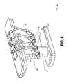
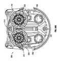
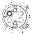
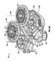
別の態様では、医療用器具の細長いシャフトの軸方向運動を容易にするように構成された駆動装置であって、駆動装置は、ロボットアームに取り付けるように構成された下面と、チャネルが形成されている上面と、を含む、ハウジングであって、チャネルは、医療用器具の細長いシャフトを受け入れるように構成されている、ハウジングと、チャネルに対して第1の側においてハウジング内に位置付けられた第1のローラと、チャネルに対して第2の側においてハウジング内に位置付けられた第2のローラと、を備えており、第1のローラ及び第2のローラは、第1の位置と第2の位置との間で移動可能であり、第1の位置では、第1のローラ及び第2のローラは、細長いシャフトと係合するように構成されており、第1の方向に回転すると、第1のローラ及び第2のローラが細長いシャフトの挿入を駆動し、第2の方向に回転すると、第1のローラ及び第2のローラが細長いシャフトの後退を駆動し、第2の位置では、第1のローラ及び第2のローラが細長いシャフトから離間されている、駆動装置、が開示される。 In another aspect, a drive configured to facilitate axial movement of an elongated shaft of a medical instrument, the drive comprising a lower surface configured for attachment to a robotic arm and a channel formed therein. a top surface, wherein the channel is configured to receive an elongated shaft of a medical instrument; and a first channel positioned within the housing on a first side relative to the channel. a roller and a second roller positioned within the housing on a second side with respect to the channel, the first roller and the second roller being positioned at a first position and at a second position; positions, wherein in the first position the first roller and the second roller are configured to engage the elongate shaft and rotate in the first direction to rotate the first roller; and a second roller drive insertion of the elongated shaft and, upon rotation in a second direction, the first and second rollers drive retraction of the elongated shaft, and in a second position, the first and a second roller spaced from an elongated shaft.
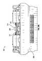
この駆動装置は、以下の特徴のうちの1つ以上を任意の組み合わせで含み得る。(a)チャネルの近位端部に位置付けられた近位クリップ、(b)チャネルの遠位端部に位置付けられた遠位クリップ、(c)近位クリップ及び遠位クリップは、細長いシャフトをチャネル内に保持するように構成されている、(d)カバーであって、第1のローラ及び第2のローラが第1の位置にあるときにチャネルを閉じ、第1のローラ及び第2のローラが第2の位置にあるときにチャネルを開くように動作可能である、カバー、(e)第1のローラ及び第2のローラが第2の位置と第1の位置との間を移動する際にカバーが開閉するように、カバーの動きが第1のローラ及び第2のローラのうちの一方の動きに機械的に連結されている、(f)第1の位置と第2の位置との間の中間位置において、カバーが閉じたままであり、かつ第1のローラ及び第2のローラは細長いシャフトから係合解除されている、(g)医療用器具を使用して患者内から回収された物体を堆積させるための、チャネルより遠位の収集器、(h)アクセスシースの近位端部を支持するように構成されたクリップ、(i)医療用器具を使用して患者内から回収された物体を堆積させるための、クリップとチャネルとの間の空間、(j)ハウジング内に位置付けられ、第1のローラを第1の位置に向かって付勢するように構成された第1のばねと、ハウジング内に位置付けられ、第2のローラを第1の位置に向かって付勢するように構成された第2のばね、(k)第1のばね及び第2のばねはトーションばねを含む、(l)ハウジング内に位置付けられ、第1の軸線を中心に回転するように構成された第1のキャリアプレートであって、第1のローラは第1のキャリアプレートに取り付けられており、第1のキャリアプレートの回転によって第1のローラが第1の位置と第2の位置との間で移動する、第1のキャリアプレートと、ハウジング内に位置付けられ、第2の軸線を中心に回転するように構成された第2のキャリアプレートであって、第2のローラは第2のキャリアプレートに取り付けられており、第2のキャリアプレートの回転によって第2のローラが第1の位置と第2の位置との間で移動する、第2のキャリアプレート、(m)ハウジングの下面に位置付けられた第1のローラ駆動入力部と、第1のキャリアプレートに取り付けられており、第1のローラ駆動入力部によって駆動される第1の歯車と、第1のキャリアプレートに取り付けられており、第1の歯車によって駆動される第1の軌道歯車であって、第1の軌道歯車の回転によって第1のローラの回転が駆動される、第1の軌道歯車と、ハウジングの下面に位置付けられた第2のローラ駆動入力部と、第2のキャリアプレートに取り付けられており、第2のローラ駆動入力部によって駆動される第2の歯車と、第2のキャリアプレートに取り付けられており、第2の歯車によって駆動される第2の軌道歯車であって、第2の軌道歯車の回転によって第2のローラの回転が駆動される、第2の軌道歯車、(n)第1のキャリアプレートが回転するときの中心である第1の軸線は、第1のローラ入力部の軸線と同軸であり、第2のキャリアプレートが回転するときの中心である第2の軸線は、第2のローラ入力部の軸線と同軸である、(o)第1のキャリアプレート及び第2のキャリアプレートのうちの一方の回転が、第1のキャリアプレート及び第2のキャリアプレートのうちの他方の回転を引き起こすように、第1のキャリアプレートと第2のキャリアプレートが互いに噛み合わされている、(p)第1のキャリアプレート又は第2のキャリアプレートのうちの一方を回転させるように構成されたキャリアプレート回転駆動入力部、(q)回転駆動入力部に連結されており、第1のキャリアプレートの回転を引き起こすためにキャリアプレートのポケットに接触するように構成された軸外突出部、及び/又は、本出願全体を通して記載される他の特徴。 The drive may include one or more of the following features in any combination. (a) a proximal clip positioned at the proximal end of the channel; (b) a distal clip positioned at the distal end of the channel; and (c) the proximal and distal clips connect the elongated shaft to the channel. (d) a cover that closes the channel when the first roller and the second roller are in the first position and the first roller and the second roller; (e) a first roller and when the second roller moves between the second position and the first position; (f) between the first position and the second position, wherein movement of the cover is mechanically coupled to movement of one of the first roller and the second roller such that the cover opens and closes automatically; in an intermediate position between the cover remains closed and the first roller and the second roller disengaged from the elongated shaft; (g) retrieved from within the patient using a medical instrument; (h) a clip configured to support the proximal end of the access sheath; (i) a collector distal to the channel for depositing the material; (j) a first spring positioned within the housing and configured to bias the first roller toward the first position; and a second spring positioned within the housing and configured to bias the second roller toward the first position; (k) the first spring and the second spring comprise torsion springs; , (l) a first carrier plate positioned within the housing and configured to rotate about a first axis, the first roller being attached to the first carrier plate; a first carrier plate positioned within the housing and rotating about a second axis, wherein rotation of the one carrier plate causes the first roller to move between a first position and a second position; wherein the second roller is attached to the second carrier plate and rotation of the second carrier plate causes the second roller to move between the first position and the second position; (m) a first roller drive input located on the underside of the housing; and attached to the first carrier plate, the first roller drive A first gear driven by the input and mounted on the first carrier plate a first orbital gear driven by the first gear, wherein rotation of the first orbital gear drives rotation of the first roller; a second roller drive input located on the underside; a second gear mounted on the second carrier plate and driven by the second roller drive input; (n) a first orbital gear driven by a second orbital gear, wherein rotation of the second orbital gear drives rotation of the second roller; The first axis around which the carrier plate of the carrier plate rotates is coaxial with the axis of the first roller input portion, and the second axis around which the second carrier plate rotates is coaxial with the axis of the first roller input portion. (o) rotation of one of the first carrier plate and the second carrier plate causes rotation of the other of the first carrier plate and the second carrier plate; (p) one of the first carrier plate or the second carrier plate is configured to rotate; a carrier plate rotational drive input; (q) an off-axis projection coupled to the rotational drive input and configured to contact a pocket of the carrier plate to cause rotation of the first carrier plate; Or other features described throughout this application.
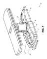
別の態様では、医療用器具の細長いシャフトの軸方向運動を容易にするように構成された駆動装置であって、駆動装置は、医療用器具の細長いシャフトを受け入れるように構成されたチャネルを含む本体と、細長いシャフトと係合するように構成されたローラであって、回転すると、ローラは、チャネル内に受け入れられた細長いシャフトの軸方向運動を駆動する、ローラと、本体に連結された第1の駆動入力部であって、第1の駆動入力部は、ローラを回転させるようにロボットシステムによって動作可能である、第1の駆動入力部と、チャネルを選択的に開く又は閉じるように構成されたカバーと、本体に連結された第2の駆動入力部であって、第2の駆動入力部は、カバーを作動させるように動作可能である、第2の駆動入力部と、を備える、駆動装置、が開示される。 In another aspect, a drive device configured to facilitate axial movement of an elongated shaft of a medical device, the drive device including a channel configured to receive the elongated shaft of the medical device. a body; a roller configured to engage the elongated shaft, the roller driving axial movement of the elongated shaft received within the channel; One drive input, the first drive input operable by the robotic system to rotate the roller and configured to selectively open or close the channel and a second drive input coupled to the body, the second drive input being operable to actuate the cover. A drive is disclosed.
この駆動装置は、以下の特徴のうちの1つ以上を任意の組み合わせで含み得る。(a)第2の駆動入力部は、カバーが細長いシャフトをチャネル内に保持する第1の位置と、カバーがチャネル内の細長いシャフトの装填又は取り外しを可能にする第2の位置との間でカバーを作動させるように動作可能である、(b)ローラを支持するキャリアであって、キャリアが、チャネル内に受け入れられた細長いシャフトを係合又は係合解除させるように、本体に連結された駆動入力部によって枢動可能である、キャリア、(c)本体は、チャネルをアクセスシースに位置合わせするようにアクセスシースに取り付けるように構成されている、(d)第2の駆動入力部は、カムを介してカバーに動作可能に連結されている、(e)チャネルにおける1つ以上のクリップ、(f)ローラは第1のローラであり、駆動装置は、第1のローラに対向する第2のローラを更に備える、及び/又は、本出願全体を通して記載される他の特徴。 The drive may include one or more of the following features in any combination. (a) the second drive input is between a first position in which the cover retains the elongate shaft within the channel and a second position in which the cover permits loading or unloading of the elongate shaft within the channel; (b) a carrier supporting the rollers, the carrier being coupled to the body to engage or disengage the elongated shaft received within the channel, operable to actuate the cover; a carrier pivotable by a drive input; (c) a body configured to attach to the access sheath to align the channel with the access sheath; (d) a second drive input; (e) one or more clips in the channel operably connected to the cover via a cam; (f) the roller is a first roller; and/or other features described throughout this application.
別の態様では、ロボット医療用システムであって、細長いシャフトを受け入れるように構成されたチャネルと、チャネル内に受け入れられた細長いシャフトに係合するように構成された1つ以上のローラと、チャネルを選択的に閉じる又は開くように構成されたカバーと、を含む、駆動装置と、ドライバであって、駆動装置を、1つ以上のローラが細長いシャフトから係合解除されており、カバーが開いている第1の状態に作動させることと、駆動装置を、1つ以上のローラが細長いシャフトから係合解除されており、カバーが閉じている第2の状態に作動させることと、駆動装置を、1つ以上のローラが細長いシャフトと係合しており、カバーが閉じている第3の状態に作動させることと、を行うように構成された、ドライバと、を備える、ロボット医療用システム、が開示される。 In another aspect, a robotic medical system comprising: a channel configured to receive an elongated shaft; one or more rollers configured to engage the elongated shaft received within the channel; a drive and a driver comprising a cover configured to selectively close or open the drive, the drive having one or more rollers disengaged from the elongated shaft such that the cover is open; operating the drive to a first condition in which the one or more rollers are disengaged from the elongate shaft and the cover is closed; operating the drive to a second condition in which the cover is closed; a driver configured to actuate a third condition in which one or more rollers are engaged with the elongated shaft and the cover is closed; is disclosed.
このロボット医療用システムは、以下の特徴のうちの1つ以上を任意の組み合わせで含み得る。(a)ドライバは、細長いシャフトを装填する又は取り外すコマンドに基づいて、駆動装置を第1の状態に作動させるように構成されている、(b)ドライバは、細長いシャフトを旋回させるコマンドに基づいて、駆動装置を第2の状態に作動させるように構成されている、(c)ドライバは、ロボットアームの端部に配置されており、ドライバは、ロボットアームを移動させるコマンドに基づいて、駆動装置を第2の状態に作動させるように構成されている、(d)ドライバは、細長いシャフトを挿入又は後退させるために駆動装置を第3の状態に作動させるように構成されている、(e)ドライバは、細長いシャフトに対してローラを回転させるように駆動装置の第1の駆動入力部を動作させ、細長いシャフトからローラを係合解除するように駆動装置の第2の駆動入力部を動作させるように構成されている、及び/又は、本出願全体に記載されている他の特徴。 The robotic medical system can include one or more of the following features in any combination. (a) the driver is configured to actuate the drive to the first state upon command to load or unload the elongate shaft; (b) the driver upon command to pivot the elongate shaft; , configured to actuate the drive to the second state; (c) a driver disposed at the end of the robot arm, the driver actuating the drive on command to move the robot arm; (d) the driver is configured to actuate the driver to a third state for inserting or retracting the elongate shaft; (e) A driver operates a first drive input of the drive to rotate the roller relative to the elongated shaft and operates a second drive input of the drive to disengage the roller from the elongated shaft. and/or other features described throughout this application.
別の態様では、ロボット医療処置の方法であって、この方法は、医療用器具の可撓性シャフトの遠位先端部が、患者に挿入されたアクセスシース内に位置付けられている第1の挿入期間中に、駆動装置によって、可撓性シャフトの挿入を第1の速度で駆動することと、可撓性シャフトの遠位先端部がアクセスシースの遠位先端部を越えて位置付けられている第2の挿入期間中に、駆動装置によって、医療用器具の可撓性シャフトの挿入を、第1の速度よりも遅い第2の速度で駆動するように移行することと、を含む、方法、が開示される。 In another aspect, a method of robotic medical procedure, the method comprising a first insertion wherein a distal tip of a flexible shaft of a medical instrument is positioned within an access sheath inserted into a patient; driving the insertion of the flexible shaft at a first speed by the drive and the distal tip of the flexible shaft being positioned beyond the distal tip of the access sheath, during a period of time; during the insertion period of 2, transitioning with the drive to drive the insertion of the flexible shaft of the medical device at a second speed that is slower than the first speed. disclosed.
この方法システムは、以下の特徴のうちの1つ以上を任意の組み合わせで含み得る。(a)駆動装置によって医療用器具の可撓性シャフトの挿入を第2の速度で駆動するように移行することは、可撓性シャフトの遠位先端部がアクセスの遠位先端部を越えて位置付けられたときを自動的に検出することを含む、(b)可撓性シャフトの遠位先端部がアクセスシースの遠位先端部を越えて位置付けられている第1の後退期間中に、駆動装置によって医療用器具の可撓性シャフトの後退を第3の速度で駆動することと、可撓性シャフトの遠位先端部がアクセスシース内に位置付けられている第2の後退期間中に、駆動装置によって医療用器具の可撓性シャフトの後退を、第3の速度よりも速い第4の速度で駆動するように自動的に移行すること、(c)駆動装置によって医療用器具の可撓性シャフトの後退を第4の速度で駆動するように自動的に移行することは、可撓性シャフトの遠位先端部がアクセスシース内に位置付けられたときを検出することを含む、(d)医療用器具の器具基部を第1のロボットアームに取り付けることと、駆動装置を第2のロボットアームに取り付けることと、医療用器具の可撓性シャフトを駆動装置と係合させること、(e)医療用器具の可撓性シャフトを駆動装置と係合させることは、駆動装置の対向するローラを可撓性シャフトと係合させることを含む、(f)医療用器具の可撓性シャフトを駆動装置と係合させることは、可撓性シャフトを駆動装置の上面におけるチャネルに挿入することを更に含む、(g)挿入中に、器具基部を第1のロボットアームによって駆動装置に向かって移動させることと、後退中に、器具基部を第1のロボットアームによって駆動装置から離れる方向に移動させること、及び/又は、本出願全体を通して記載される他の特徴。 The method system can include one or more of the following features, in any combination. (a) transitioning the drive to drive insertion of the flexible shaft of the medical instrument at a second speed is such that the distal tip of the flexible shaft extends beyond the distal tip of the access; (b) during a first retraction period in which the distal tip of the flexible shaft is positioned beyond the distal tip of the access sheath; driving retraction of the flexible shaft of the medical instrument at a third rate by the device; and during a second retraction period in which the distal tip of the flexible shaft is positioned within the access sheath. (c) automatically transitioning retraction of the flexible shaft of the medical instrument by the device to drive at a fourth speed, which is greater than the third speed; (d) medical attaching an instrument base of a medical instrument to a first robotic arm; attaching a driver to a second robotic arm; engaging a flexible shaft of a medical instrument with the driver; (f) engaging the flexible shaft of the medical instrument with the driver includes engaging opposing rollers of the driver with the flexible shaft; further comprising inserting the flexible shaft into a channel in the upper surface of the drive; (g) moving the instrument base toward the drive by the first robotic arm during insertion; and, during retraction, moving the instrument base away from the drive by the first robotic arm, and/or other features described throughout this application.
別の態様では、ロボット医療用システムであって、医療用器具のシャフトに係合するように構成された一対のローラを含む駆動装置と、プロセッサであって、シャフトの遠位先端部が、患者に挿入されたアクセスシース内に位置付けられている第1の挿入期間中に、シャフトの挿入を第1の速度で駆動するようにローラを動作させることと、シャフトの遠位先端部がアクセスシースの遠位先端部を越えて位置付けられている第2の挿入期間中に、シャフトの挿入を、第1の速度よりも遅い第2の速度で駆動するように移行するようにローラを動作させることと、を行うように構成された、プロセッサと、を備える、ロボット医療用システム、が開示される。 In another aspect, a robotic medical system, a drive including a pair of rollers configured to engage a shaft of a medical instrument; and a processor, wherein a distal tip of the shaft operating the rollers to drive insertion of the shaft at a first speed during a first insertion period positioned within the access sheath inserted into the access sheath; operating the roller during a second insertion period positioned beyond the distal tip to transition the insertion of the shaft to drive at a second speed that is lower than the first speed; A robotic medical system is disclosed, comprising a processor configured to:
このロボット医療用システムは、以下の特徴のうちの1つ以上を任意の組み合わせで含み得る。(a)プロセッサは、シャフトの遠位先端部がアクセスシースの遠位先端部を越えて位置付けられているときを、アクセスシース及びシャフトに関連付けられた幾何学的情報に基づいて検出するように構成されている、(b)プロセッサは、シャフトの遠位先端部がアクセスシースの遠位先端部を越えて位置付けられているときを、医療用器具によって得られた画像情報に基づいて検出するように構成されている、(c)プロセッサは、シャフトの遠位先端部がアクセスシースの遠位先端部を越えて位置付けられている第1の後退期間中に、医療用器具のシャフトの後退を第3の速度で駆動するようにローラを動作させることと、シャフトの遠位先端部がアクセスシース内に位置付けられている第2の後退期間中に、医療用器具のシャフトの後退を、第3の速度より速い第4の速度で駆動するように移行するようにローラを動作させることと、を行うように更に構成されている、(d)医療用器具を支持するように構成された第1のロボットアームと、駆動装置を支持するように構成された第2のロボットアーム、(e)第1のロボットアームは、挿入中に医療用器具の器具ハンドルを駆動装置に向かって移動させるように構成されており、第1のロボットアームは、後退中に器具ハンドルを駆動装置から離れる方向に移動させるように構成されている、及び/又は、本出願全体を通して記載される他の特徴。 The robotic medical system may include one or more of the following features in any combination. (a) the processor is configured to detect when the distal tip of the shaft is positioned beyond the distal tip of the access sheath based on geometric information associated with the access sheath and the shaft; (b) the processor detects when the distal tip of the shaft is positioned beyond the distal tip of the access sheath based on image information obtained by the medical instrument; (c) the processor causes retraction of the shaft of the medical instrument to a third retraction period during a first retraction period in which the distal tip of the shaft is positioned beyond the distal tip of the access sheath; and during a second retraction period in which the distal tip of the shaft is positioned within the access sheath, retraction of the shaft of the medical instrument at a third rate of (d) a first robot configured to support a medical instrument; an arm and a second robotic arm configured to support the drive; (e) the first robotic arm configured to move an instrument handle of the medical instrument toward the drive during insertion; and the first robotic arm is configured to move the instrument handle away from the drive during retraction and/or other features described throughout this application.
別の態様では、ロボット医療用システムであって、細長い可撓性アクセスシースと、細長い可撓性シャフトを含む医療用器具と、プロセッサであって、シャフトの遠位先端部がアクセスシース内に位置付けられている第1の挿入期間中に、シャフトの挿入を第1の速度で駆動することと、シャフトの遠位先端部がアクセスシースの遠位先端部を越えて位置付けられる第2の挿入期間中に、シャフトの挿入を、第1の速度よりも遅い第2の速度で駆動するように移行することと、を行うように構成された、プロセッサと、を備える、ロボット医療用システム、が開示される。 In another aspect, a robotic medical system, comprising: an elongated flexible access sheath; a medical instrument including an elongated flexible shaft; and a processor, wherein a distal tip of the shaft is positioned within the access sheath. driving insertion of the shaft at a first speed during a first insertion period during which the distal tip of the shaft is positioned beyond the distal tip of the access sheath during a second insertion period; a processor configured to transition the insertion of the shaft to drive at a second speed that is slower than the first speed; be.
このロボット医療用システムは、以下の特徴のうちの1つ以上を任意の組み合わせで含み得る。(a)プロセッサは、シャフトの遠位先端部がアクセスシースの遠位先端部を越えて位置付けられているときを、アクセスシース及びシャフトに関連付けられた幾何学的情報に基づいて検出するように構成されている、(b)プロセッサは、シャフトの遠位先端部がアクセスシースの遠位先端部を越えて位置付けられているときを、医療用器具によって得られた画像情報に基づいて検出するように構成されている、(c)プロセッサは、シャフトの遠位先端部がアクセスシースの遠位先端部を越えて位置付けられている第1の後退期間中に、医療用器具のシャフトの後退を第3の速度で駆動することと、シャフトの遠位先端部がアクセスシース内に位置付けられている第2の後退期間中に、医療用器具のシャフトの後退を、第3の速度よりも速い第4の速度で駆動するように移行することと、を行うように更に構成されている、(d)プロセッサは、細長い可撓性シャフトの軸方向運動を駆動するように駆動装置を動作させることと、挿入中に医療用器具の器具ハンドルを駆動装置に向かって移動させることと、後退中に器具ハンドルを駆動装置から離れる方向に移動させることと、を行うように構成されている、及び/又は、本出願全体を通して記載される他の特徴。 The robotic medical system can include one or more of the following features in any combination. (a) the processor is configured to detect when the distal tip of the shaft is positioned beyond the distal tip of the access sheath based on geometric information associated with the access sheath and the shaft; (b) the processor detects when the distal tip of the shaft is positioned beyond the distal tip of the access sheath based on image information obtained by the medical instrument; (c) the processor causes retraction of the shaft of the medical instrument to a third retraction period during a first retraction period in which the distal tip of the shaft is positioned beyond the distal tip of the access sheath; and retracting the shaft of the medical instrument at a fourth speed, which is faster than the third speed, during a second retraction period in which the distal tip of the shaft is positioned within the access sheath. (d) the processor operating the drive to drive axial motion of the elongated flexible shaft; during retraction and/or moving the instrument handle away from the drive during retraction; Other features described throughout the application.
開示される態様は、以下、添付の図面と併せて説明され、開示された態様を例示するが、限定するものではなく、同様の称号は同様の要素を示す。
1.概論
本開示の態様は、腹腔鏡などの低侵襲性、及び内視鏡などの非侵襲性の両方の処置を含む、様々な医療処置を行うことができるロボットで使用可能な医療用システムに統合され得る。内視鏡処置のうち、システムは、気管支鏡検査、尿管鏡検査、胃鏡検査などを行うことができる。1. Overview Aspects of the present disclosure are integrated into a robotically usable medical system capable of performing a variety of medical procedures, including both minimally invasive, such as laparoscopic, and non-invasive, such as endoscopic procedures. can be Among endoscopic procedures, the system can perform bronchoscopies, ureteroscopies, gastroscopies, and the like.
幅広い処置を行うことに加えて、システムは、医師を支援するための強調された撮像及び誘導などの追加の利益を提供することができる。追加的に、システムは、厄介な腕の動作及び姿勢を必要とせずに、人間工学的位置から処置を行う能力を医師に提供することができる。また更に、システムは、システムの器具のうちの1つ以上が単一のユーザーによって制御され得るように、改善された使いやすさで処置を行う能力を医師に提供することができる。 In addition to performing a wide range of procedures, the system can provide additional benefits such as enhanced imaging and guidance to assist physicians. Additionally, the system can provide the physician with the ability to perform procedures from an ergonomic position without the need for awkward arm movements and postures. Still further, the system can provide the physician with the ability to perform procedures with improved ease of use, as one or more of the instruments of the system can be controlled by a single user.
以下、説明を目的として、図面と併せて、様々な実施形態が説明される。開示される概念の多くの他の実装態様が可能であり、開示される実装態様で様々な利点が達成され得ることを理解されたい。見出しが、参照のために本明細書に含まれ、様々なセクションの位置を特定する支援となる。これらの見出しは、それに関して説明される概念の範囲を限定することを意図するものではない。そのような概念は、本明細書全体にわたって適用可能性を有し得る。 Various embodiments are described below, for purposes of illustration, in conjunction with the drawings. It is to be understood that many other implementations of the disclosed concepts are possible and various advantages may be achieved with the disclosed implementations. Headings are included herein for reference to aid in locating the various sections. These headings are not intended to limit the scope of the concepts described therewith. Such concepts may have applicability throughout the specification.
A.ロボットシステム-カート
ロボットで使用可能な医療用システムは、特定の処置に応じて様々な方法で構成され得る。図1は、診断及び/又は治療用気管支鏡検査のために配置された、ロボットで使用可能なカートベースのシステム10の実施形態を示す。気管支鏡検査の間、システム10は、気管支鏡検査のための処置専用気管支鏡であり得る操縦可能な内視鏡13などの医療用器具を、診断及び/又は治療ツールを送達するための自然開口部アクセスポイント(すなわち、本実施例ではテーブル上に位置付けられている患者の口)に送達するための1つ以上のロボットアーム12を有するカート11を含むことができる。示されるように、カート11は、アクセスポイントへのアクセスを提供するために、患者の上部胴体に近接して位置付けられてよい。同様に、ロボットアーム12は、アクセスポイントに対して気管支鏡を位置付けるために作動させることができる。図1の配置はまた、胃腸管(gastro-intestinal、GI)処置を、GI処置のための特殊な内視鏡である胃鏡を用いて行うときに利用することができる。図2は、カートの例示的な実施形態をより詳細に示す。A. Robotic Systems—Cart Robotically usable medical systems can be configured in a variety of ways, depending on the particular procedure. FIG. 1 illustrates an embodiment of a robotically usable cart-based system 10 deployed for diagnostic and/or therapeutic bronchoscopy. During a bronchoscopy, the system 10 connects medical instruments such as a
図1を引き続き参照し、カート11が適切に位置付けられると、ロボットアーム12は、操縦可能な内視鏡13をロボットで、手動で、又はそれらの組み合わせで患者内に挿入することができる。示されるように、操縦可能な内視鏡13は、内側リーダ部分及び外側シース部分などの少なくとも2つの入れ子式部品を含んでもよく、各部分は、器具ドライバの組28から別個の器具ドライバに連結され、各器具ドライバは、個々のロボットアームの遠位端部に連結されている。リーダ部分をシース部分と同軸上に位置合わせするのを容易にする、器具ドライバ28のこの直線配置は、1つ以上のロボットアーム12を異なる角度及び/又は位置に操作することによって空間内に再位置付けされ得る「仮想レール」29を作成する。本明細書に記載される仮想レールは、破線を使用して図に示されており、したがって破線は、システムの物理的構造を示さない。仮想レール29に沿った器具ドライバ28の並進は、外側シース部分に対して内側リーダ部分を入れ子にするか、又は内視鏡13を患者から前進若しくは後退させる。仮想レール29の角度は、臨床用途又は医師の好みに基づいて調整、並進、及び枢動させられてもよい。例えば、気管支鏡検査では、示されるような仮想レール29の角度及び位置は、内視鏡13を患者の口内に曲げ入れることによる摩擦を最小限に抑えながら内視鏡13への医師のアクセスを提供する妥協を表す。 With continued reference to FIG. 1, once the cart 11 is properly positioned, the
内視鏡13は、標的の目的地又は手術部位に到達するまで、ロボットシステムからの正確なコマンドを使用して挿入後に患者の気管及び肺の下方に向けられてもよい。患者の肺網を通したナビゲーションを高め、及び/又は所望の標的に到達するために、内視鏡13を操縦して、内側リーダ部分を外側シース部分から入れ子状に延在させ、高められた関節運動及びより大きな曲げ半径を得てもよい。別個の器具ドライバ28の使用により、リーダ部分及びシース部分が互いに独立して駆動されることも可能となる。 The
例えば、内視鏡13は、例えば、患者の肺内の病変又は小結節などの標的に生検針を送達するように方向付けられてもよい。針は、内視鏡の長さにわたるワーキングチャネルの下方に展開されて、病理医によって分析される組織サンプルを得てもよい。病理の結果に応じて、追加の生検のために追加のツールが内視鏡のワーキングチャネルの下方に展開されてもよい。小結節を悪性と識別した後、内視鏡13は、潜在的な癌組織を切除するためにツールを内視鏡的に送達してもよい。場合によっては、診断及び治療的処置は、別々の手順で提供することができる。これらの状況において、内視鏡13はまた、標的小結節の場所を「マーク」するために基準を送達するのに使用されてもよい。他の例では、診断及び治療的処置は、同じ処置中に送達されてもよい。 For example,
システム10はまた、カート11に支持ケーブルを介して接続されて、カート11への制御、電子機器、流体工学、光学系、センサ、及び/又は電力のためのサポートを提供し得る移動可能なタワー30を含んでもよい。タワー30内にこのような機能を置くことにより、動作を行う医師及びそのスタッフがより容易に調整及び/又は再位置付けすることができるより小さいフォームファクタのカート11が可能となる。追加的に、カート/テーブルと支持タワー30との間の機能の分割は、手術室の乱雑さを低減し、臨床ワークフローの改善を促進する。カート11は患者に近接して位置付けられてもよいが、タワー30は、処置中に邪魔にならないように離れた場所に格納されてもよい。 System 10 is also a movable tower that may be connected to cart 11 via support cables to provide support for controls, electronics, fluidics, optics, sensors, and/or power to cart 11. 30 may be included. Placing such functionality within
上述のロボットシステムのサポートにおいて、タワー30は、例えば、永続的な磁気記憶ドライブ、ソリッドステートドライブなどの非一時的コンピュータ可読記憶媒体内にコンピュータプログラム命令を記憶するコンピュータベースの制御システムの構成要素を含んでもよい。これらの命令の実行は、実行がタワー30内で行われるのか又はカート11で行われるのかにかかわらず、システム全体又はそのサブシステムを制御してもよい。例えば、コンピュータシステムのプロセッサによって実行されるとき、命令は、ロボットシステムの構成要素に、関連するキャリッジ及びアームマウントを作動させ、ロボットアームを作動させ、医療用器具を制御させてもよい。例えば、制御信号を受信したことに応答して、ロボットアームの接合部内のモータは、アームをある特定の姿勢に位置付けてもよい。 In support of the robotic system described above, the
タワー30は、内視鏡13を通して配備することができるシステムに、制御された灌注及び吸引機能を提供するために、ポンプ、流量計、弁制御、及び/又は流体アクセスも含むことができる。これらの構成要素はまた、タワー30のコンピュータシステムを使用して制御されてもよい。いくつかの実施形態では、灌注及び吸引能力は、別個のケーブルを通して内視鏡13に直接送達されてもよい。
タワー30は、フィルタリングされ、保護された電力をカート11に提供するように設計された電圧及びサージ保護具を含んでもよく、それによって、カート11内に電力変圧器及び他の補助電力構成要素を配置することが回避され、カート11はより小さく、より移動可能になる。
タワー30は、ロボットシステム10全体に配備されたセンサのための支持機器も含んでもよい。例えば、タワー30は、ロボットシステム10全体の光センサ又はカメラから受信したデータを検出、受信、及び処理するためのオプトエレクトロニクス機器を含んでもよい。制御システムと組み合わせて、このようなオプトエレクトロニクス機器は、タワー30内を含むシステム全体に展開された任意の数のコンソール内に表示するためのリアルタイム画像を生成するために使用されてもよい。同様に、タワー30はまた、展開された電磁(electromagnetic、EM)センサから信号を受信し、受信した信号を処理するための電子サブシステムも含んでもよい。タワー30はまた、医療用器具内又は医療用器具上のEMセンサによる検出のためにEM場発生器を収容し、位置付けるためにも使用されてもよい。
タワー30はまた、システムの残りの部分で利用可能な他のコンソール、例えば、カートの上部上に装着されたコンソールに追加して、コンソール31を含んでもよい。コンソール31は、オペレータである医師のためのユーザーインターフェース及びタッチスクリーンなどの表示画面を含んでもよい。システム10内のコンソールは、一般に、ロボット制御、並びに内視鏡13のナビゲーション情報及び位置特定情報などの処置の術前及びリアルタイム情報の両方を提供するように設計される。コンソール31が医師に利用可能な唯一のコンソールではない場合、コンソール31は、看護師などの第2のオペレータによって使用されて、患者の健康又はバイタル、及びシステム10の動作を監視し、並びにナビゲーション及び位置特定情報などの処置固有のデータを提供してもよい。別の実施形態では、コンソール31は、タワー30とは別個の本体内に収容される。
タワー30は、1つ以上のケーブル又は接続部(図示せず)を介してカート11及び内視鏡13に連結されてもよい。いくつかの実施形態では、タワー30からのサポート機能は、単一ケーブルを通してカート11に提供されることにより、手術室を簡略化し、整理整頓することができる。他の実施形態では、特定の機能は、別個の配線及び接続部で連結されてもよい。例えば、単一の電力ケーブルを通してカート11に電力が供給されてもよい一方、制御、光学、流体工学、及び/又はナビゲーションのためのサポートは、別個のケーブルを通して提供されてもよい。
図2は、図1に示されるロボットで使用可能なカートベースのシステムからのカート11の実施形態の詳細な図を提供する。カート11は、概して、細長い支持構造14(「カラム」と呼ばれることが多い)、カート基部15、及びカラム14の頂部にあるコンソール16を含む。カラム14は、1つ以上のロボットアーム12(図2には3つ示されている)の展開を支持するためのキャリッジ17(代替的に「アーム支持体」)などの1つ以上のキャリッジを含んでもよい。キャリッジ17は、患者に対してより良好に位置付けるために垂直軸線に沿って回転してロボットアーム12の基部を調整する、個別に構成可能なアームマウントを含んでもよい。キャリッジ17はまた、キャリッジ17がカラム14に沿って垂直方向に並進することを可能にするキャリッジインターフェース19を含む。 FIG. 2 provides a detailed view of an embodiment of the cart 11 from the robotic cart-based system shown in FIG. Cart 11 generally includes an elongated support structure 14 (often referred to as a “column”), a
キャリッジインターフェース19は、キャリッジ17の垂直方向の並進を案内するためにカラム14の両側に位置付けられているスロット20などのスロットを通してカラム14に接続されている。スロット20は、カート基部15に対して様々な垂直方向の高さでキャリッジ17を位置付け、保持するための垂直方向の並進インターフェースを含む。キャリッジ17の垂直方向の並進により、カート11は、様々なテーブルの高さ、患者のサイズ、及び医師の好みを満たすようにロボットアーム12のリーチを調整することが可能となる。同様に、キャリッジ17上の個別に構成可能なアームマウントにより、ロボットアーム12のロボットアーム基部21を様々な構成で角度付けすることが可能となる。 Carriage interface 19 is connected to column 14 through slots such as
いくつかの実施形態では、キャリッジ17が垂直方向に並進するときにカラム14の内部チャンバ及び垂直方向の並進インターフェース内に汚れ及び流体が侵入するのを防止するために、スロット20には、スロット表面と同一平面及び平行であるスロットカバーが追加されてもよい。スロットカバーは、スロット20の垂直方向の頂部及び底部付近に位置付けられているばねスプールの対を通じて展開されてもよい。カバーは、キャリッジ17が上下に垂直方向に並進するにつれてコイル状から伸縮するように展開されるまで、スプール内でコイル巻きにされている。スプールのばね荷重は、キャリッジ17がスプールに向かって並進する場合にカバーをスプールに引き込む力を提供し、一方、キャリッジ17がスプールから離れて並進する場合にはぴったりとした封止も維持する。カバーは、キャリッジ17が並進するときにカバーが適切に伸縮するのを確実にするために、例えば、キャリッジインターフェース19内のブラケットを使用してキャリッジ17に接続されてもよい。 In some embodiments, to prevent dirt and fluid from entering the internal chamber and vertical translation interface of column 14 as
カラム14は、例えば、コンソール16からの入力などのユーザー入力に応答して生成された制御信号に応答してキャリッジ17を機械的に並進させるために垂直方向に位置合わせされた主ねじを使用するように設計された、歯車及びモータなどの機構を内部に含んでもよい。 Column 14 uses a vertically aligned lead screw to mechanically translate
ロボットアーム12は、一般に、一連の接合部24によって接続されている一連のリンク23によって分離されたロボットアーム基部21及びエンドエフェクタ22を含んでもよく、各接合部は独立したアクチュエータを含み、各アクチュエータは、独立して制御可能なモータを含む。独立して制御可能な各接合部は、ロボットアーム12が利用可能な独立した自由度を表す。ロボットアーム12の各々は、7つの接合部を有してもよく、したがって、7つの自由度を提供することが可能である。多数の接合部は、多数の自由度をもたらし、「冗長」自由度を可能にする。冗長自由度を有することにより、ロボットアーム12は、異なるリンク位置及び接合部角度を使用して空間内の特定の位置、向き、及び軌道で、それらのそれぞれのエンドエフェクタ22を位置付けることが可能となる。これにより、システムが空間内の所望のポイントから医療用器具を位置付け、方向付けることが可能になると同時に、医師がアーム接合部を患者から離れる臨床的に有利な位置へと移動させて、アームの衝突を回避しながらよりよいアクセスを生み出すことを可能にする。 The
カート基部15は、床の上のカラム14、キャリッジ17、及びロボットアーム12の重量の釣り合いをとる。したがって、カート基部15は、電子機器、モータ、電源、並びにカート11の移動及び/又は固定化のいずれかを可能にする構成要素などの、より重い部品を収容する。例えば、カート基部15は、処置前にカート11が部屋中をあちこちに容易に移動することを可能にする、転動可能なホイール形状のキャスタ25を含む。適切な位置に到達した後、キャスタ25は、処置中にカート11を所定の場所に保持するためのホイールロックを使用して静止させられてもよい。 The
カラム14の垂直方向の端部に位置付けられたコンソール16は、ユーザー入力を受信するためのユーザーインターフェース及び表示画面(又は、例えば、タッチスクリーン26などの二重目的デバイス)の両方を可能にして、術前データ及び術中データの両方を医師であるユーザーに提供する。タッチスクリーン26上の潜在的な術前データは、術前計画、術前コンピュータ断層撮影(computerized tomography、CT)スキャンから導出されたナビゲーション及びマッピングデータ、並びに/又は術前の患者への問診からのメモを含んでもよい。ディスプレイ上の術中データは、ツールから提供される光学情報、センサからのセンサ及び座標情報、並びに呼吸、心拍数、及び/又はパルスなどの不可欠な患者統計を含んでもよい。コンソール16は、医師が、キャリッジ17の反対側のカラム14側からコンソール16にアクセスすることを可能にするように位置付けられ、傾斜が付けられてもよい。この位置から、医師は、コンソール16をカート11の背後から操作しながら、コンソール16、ロボットアーム12、及び患者を見ることができる。示されるように、コンソール16はまた、カート11の操作及び安定化を支援するハンドル27を含む。
図3は、尿管鏡検査のために配置された、ロボットで使用可能なシステム10の実施形態を示す。尿管鏡検査処置では、カート11は、患者の尿道及び尿管を横断するように設計された処置専用内視鏡である尿管鏡32を患者の下腹部領域に送達するように位置付けられてもよい。尿管鏡検査では、尿管鏡32が患者の尿道と直接位置合わせされ、領域内の敏感な解剖学的構造に対する摩擦及び力を低減することが望ましいことがある。示されるように、カート11は、ロボットアーム12が尿管鏡32を、患者の尿道に直線状に直接アクセスするために位置付けることを可能にするように、テーブルの脚部に位置合わせされてもよい。テーブルの脚部から、ロボットアーム12は、尿道を通して患者の下腹部に直接、仮想レール33に沿って尿管鏡32を挿入してもよい。 FIG. 3 shows an embodiment of a robot-enabled system 10 configured for ureteroscopy. In a ureteroscopy procedure, cart 11 is positioned to deliver
気管支鏡検査におけるのと同様の制御技法を使用して尿道に挿入した後、尿管鏡32は、診断及び/又は治療用途のために、膀胱、尿管、及び/又は腎臓にナビゲートされてもよい。例えば、尿管鏡32を尿管及び腎臓に方向付けて、尿管鏡32のワーキングチャネルの下方に配備されたレーザー又は超音波結石破砕デバイスを使用して、腎臓結石の蓄積を破砕することができる。砕石術が完了した後、結果として得られた結石片は、尿管鏡32の下方に配備されたバスケットを使用して除去されてもよい。 After insertion into the urethra using control techniques similar to those in bronchoscopy, the
図4は、血管処置のために同様に配置された、ロボットで使用可能なシステム10の実施形態を示す。血管処置において、システム10は、カート11が、操縦可能なカテーテルなどの医療用器具34を、患者の脚内の大腿動脈内のアクセスポイントに送達することができるように構成され得る。大腿動脈は、ナビゲーションのためのより大きな直径と、患者の心臓への、遠回りが比較的少ない曲がりくねった経路の両方を示すが、これはナビゲーションを簡素化する。尿管鏡検査処置のように、カート11は、患者の脚及び下腹部に向かって位置付けられて、ロボットアーム12が患者の大腿/腰領域内の大腿動脈アクセスポイントへの直接的な線形アクセスで仮想レール35を提供することを可能にしてもよい。動脈内への挿入後、器具ドライバ28を並進させることによって医療用器具34が方向付けられ、挿入されてもよい。代替的には、カートは、例えば、肩及び手首付近の頸動脈及び腕動脈などの代替的な血管アクセスポイントに到達するために、患者の上腹部の周囲に位置付けられてもよい。 FIG. 4 shows an embodiment of a robot-enabled system 10 similarly arranged for vascular procedures. In a vascular procedure, the system 10 may be configured so that the cart 11 can deliver a medical device 34, such as a steerable catheter, to an access point within the femoral artery within the patient's leg. The femoral artery presents both a larger diameter for navigation and a relatively less circuitous and tortuous path to the patient's heart, which simplifies navigation. As in a ureteroscopy procedure, the cart 11 is positioned toward the patient's legs and lower abdomen so that the
B.ロボットシステム-テーブル
ロボットで使用可能な医療用システムの実施形態は、患者テーブルも組み込んでもよい。テーブルの組み込みは、カートをなくすことによって手術室内の資本設備の量を低減し、患者へのより大きなアクセスを可能にする。図5は、気管支鏡検査処置のために配置された、そのようなロボットで使用可能なシステムの実施形態を示す。システム36は、床の上にプラットフォーム38(「テーブル」又は「ベッド」として図示)を支持するための支持構造体又はカラム37を含む。カートベースのシステムと同様に、システム36のロボットアーム39のエンドエフェクタは、器具ドライバ42の線形アライメントから形成された仮想レール41を通して、又はそれに沿って、図5の気管支鏡40などの細長い医療用器具を操作するように設計された器具ドライバ42を含む。実際には、蛍光透視撮像を提供するためのCアームは、放射器及び検出器をテーブル38の周囲に置くことによって、患者の上部腹部領域の上方に位置付けられてもよい。B. Robotic System—Table Embodiments of the robotic-enabled medical system may also incorporate a patient table. Incorporating a table reduces the amount of capital equipment in the operating room by eliminating carts and allows greater access to the patient. FIG. 5 shows an embodiment of such a robot-enabled system deployed for a bronchoscopy procedure.
図6は、説明を目的として、患者及び医療用器具なしのシステム36の代替的な図を提供する。示されるように、カラム37は、1つ以上のロボットアーム39の基部となり得る、システム36内でリング形状として図示される1つ以上のキャリッジ43を含んでもよい。キャリッジ43は、カラム37の長さにわたる垂直方向のカラムインターフェース44に沿って並進して、ロボットアーム39が患者に到達するように位置付けられ得る異なるバンテージポイントを提供してもよい。キャリッジ43は、カラム37内に位置付けられている機械的モータを使用してカラム37の周りを回転して、ロボットアーム39が、例えば、患者の両側などのテーブル38の多数の側部へのアクセスを有することを可能にしてもよい。複数のキャリッジを有する実施形態では、キャリッジはカラム上に個別に位置付けられてもよく、他のキャリッジとは独立して並進及び/又は回転してもよい。キャリッジ43はカラム37を取り囲む必要はなく、又は更には円形である必要もないが、図示されるようなリング形状は、構造的バランスを維持しながらカラム37の周りでのキャリッジ43の回転を容易にする。キャリッジ43の回転及び並進により、システム36は、内視鏡及び腹腔鏡などの医療用器具を患者の異なるアクセスポイントに位置合わせすることができる。他の実施形態(図示せず)では、システム36は、並行して延在するバー又はレールの形態の調整可能なアーム支持体を有する患者テーブル又はベッドを含むことができる。1つ以上のロボットアーム39を、(例えば、エルボ接合部を有するショルダを介して)垂直方向に調整することができる調整可能なアーム支持体に取り付けることができる。垂直方向の調節を提供することによって、ロボットアーム39は、有利には、患者テーブル又はベッドの下にコンパクトに収容されることが可能であり、その後、処置中に引き上げられることが可能である。 FIG. 6 provides an alternative view of the
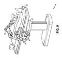
ロボットアーム39は、ロボットアーム39に追加の構成可能性を提供するために個別に回転及び/又は入れ子式に延在し得る一連の接合部を含むアームマウント45の組を介してキャリッジ43に装着されてもよい。追加的に、アームマウント45は、キャリッジ43が適切に回転されると、アームマウント45がテーブル38の同じ側(図6に示すように)、テーブル38の両側(図9に示すように)、又はテーブル38の隣接する側部(図示せず)のいずれかに位置付けられ得るように、キャリッジ43上に位置付けられ得る。 The
カラム37は、テーブル38の支持及びキャリッジ43の垂直方向の並進のための経路を構造的に提供する。内部に、カラム37は、キャリッジの垂直方向の並進を案内するための主ねじ、及び主ねじに基づくキャリッジ43の並進を機械化するためのモータを備えていてもよい。カラム37はまた、キャリッジ43及びその上に装着されたロボットアーム39に電力及び制御信号を伝達してもよい。
テーブル基部46は、図2に示すカート11のカート基部15と同様の機能を果たし、テーブル/ベッド38、カラム37、キャリッジ43、及びロボットアーム39の釣り合いをとるためにより重い構成要素を収容する。テーブル基部46はまた、処置中に安定性を提供するために剛性キャスタを組み込んでもよい。テーブル基部46の底部から展開されるキャスタは、基部46の両側で反対方向に延在し、システム36を移動させる必要があるときに引き込んでもよい。
引き続き図6を参照すると、システム36はまた、テーブルとタワーとの間でシステム36の機能を分割して、テーブルのフォームファクタ及びバルクを低減するタワー(図示せず)を含んでもよい。先に開示された実施形態と同様に、タワーは、処理、計算、及び制御能力、電力、流体工学、並びに/又は光学及びセンサ処理などの様々なサポート機能をテーブルに提供してもよい。タワーはまた、医師のアクセスを改善し、手術室を整理整頓するために、患者から離れて位置付けられるように移動可能であってもよい。追加的に、タワー内に構成要素を配置することにより、ロボットアーム39の潜在的な収容のために、テーブル基部46内により多くの保管空間を可能にする。タワーはまた、キーボード及び/又はペンダントなどのユーザー入力のためのユーザーインターフェースと、リアルタイム撮像、ナビゲーション、及び追跡情報などの術前及び術中情報のための表示画面(又はタッチスクリーン)との両方を提供するマスターコントローラ又はコンソールも含んでもよい。いくつかの実施形態では、タワーはまた、送気のために使用されるガスタンク用のホルダを含んでもよい。 With continued reference to FIG. 6,
いくつかの実施形態では、テーブル基部は、使用されていないときにロボットアームを収容して格納してもよい。図7は、テーブルベースのシステムの実施形態におけるロボットアームを収容するシステム47を示す。システム47では、キャリッジ48は、ロボットアーム50、アームマウント51、及びキャリッジ48を基部49内に収容するために、基部49内へと垂直方向に並進させられてもよい。基部カバー52は、並進及び後退して、キャリッジ48、アームマウント51、及びロボットアーム50をカラム53の周りに展開させるように開き、使用されていないときにそれらを収容して保護するように閉じられてもよい。基部カバー52は、閉じたときに汚れ及び流体の侵入を防止するために、その開口部の縁部に沿って膜54で封止されてもよい。 In some embodiments, the table base may house and store the robotic arm when not in use. FIG. 7 shows a
図8は、尿管鏡検査処置のために構成されたロボットで使用可能なテーブルベースシステムの実施形態を示す。尿管鏡検査では、テーブル38は、患者をカラム37及びテーブル基部46からオフアングルに位置付けるためのスイベル部分55を含んでもよい。スイベル部分55は、スイベル部分55の底部をカラム37から離すように位置付けるために、枢動点(例えば、患者の頭部の下方に配置)を中心に回転又は枢動してもよい。例えば、スイベル部分55の枢動により、Cアーム(図示せず)が、テーブル38の下のカラム(図示せず)と空間を奪い合うことなく、患者の下部腹部の上方に位置付けられることを可能にする。カラム37の周りにキャリッジ(図示せず)を回転させることにより、ロボットアーム39は、尿道に到達するように、仮想レール57に沿って、患者の鼠径部領域に尿管鏡56を直接挿入してもよい。尿管鏡検査では、処置中に患者の脚の位置を支持し、患者の鼠径部領域への明確なアクセスを可能にするために、テーブル38のスイベル部分55にあぶみ58が固定されてもよい。 FIG. 8 illustrates an embodiment of a robot-usable table-based system configured for ureteroscopy procedures. For ureteroscopy, table 38 may include a swivel portion 55 for positioning the patient off-angle from
腹腔鏡処置では、患者の腹壁内の小さな切開部を通して、低侵襲性器具を患者の解剖学的構造に挿入してもよい。いくつかの実施形態では、低侵襲性器具は、患者内の解剖学的構造にアクセスするために使用されるシャフトなどの細長い剛性部材を含む。患者の腹腔の膨張後、器具は、把持、切断、アブレーション、縫合などの外科的又は医療的タスクを実施するように方向付けられてもよい。いくつかの実施形態では、器具は、腹腔鏡などのスコープを含むことができる。図9は、腹腔鏡処置のために構成されたロボットで使用可能なテーブルベースのシステムの実施形態を示す。図9に示されるように、システム36のキャリッジ43は回転し、垂直方向に調整されて、器具59が患者の両側の最小切開部を通過して患者の腹腔に到達するようアームマウント45を使用して位置付けられ得るように、ロボットアーム39の対をテーブル38の両側に位置付けてもよい。 In a laparoscopic procedure, minimally invasive instruments may be inserted into the patient's anatomy through small incisions in the patient's abdominal wall. In some embodiments, a minimally invasive instrument includes an elongate rigid member, such as a shaft, used to access anatomy within a patient. After inflation of the patient's abdominal cavity, the instruments may be directed to perform surgical or medical tasks such as grasping, cutting, ablating, suturing, and the like. In some embodiments, the instrument can include a scope, such as a laparoscope. FIG. 9 illustrates an embodiment of a robot-usable table-based system configured for laparoscopic procedures. As shown in FIG. 9,
腹腔鏡処置に対応するために、ロボットで使用可能なテーブルシステムはまた、プラットフォームを所望の角度に傾斜させてもよい。図10は、ピッチ又は傾斜調整を有するロボットで使用可能な医療用システムの実施形態を示す。図10に示されるように、システム36は、テーブル38の傾斜に適応して、テーブルの一方の部分を他方の部分より床から離れた距離に位置付けることができる。追加的に、アームマウント45は、ロボットアーム39がテーブル38と同じ平面関係を維持するように、傾斜に一致するように回転してもよい。より急な角度に適応するために、カラム37はまた、テーブル38が床に接触したりテーブル基部46と衝突したりするのを防ぐためにカラム37が垂直方向に延在するのを可能にする入れ子部分60を含んでもよい。 To accommodate laparoscopic procedures, the robotic table system may also tilt the platform to a desired angle. FIG. 10 shows an embodiment of a medical system that can be used on a robot with pitch or tilt adjustment. As shown in FIG. 10, the
図11は、テーブル38とカラム37との間のインターフェースの詳細な図を提供する。ピッチ回転機構61は、カラム37に対するテーブル38のピッチ角を多数の自由度で変更するように構成されてもよい。ピッチ回転機構61は、カラム-テーブルインターフェースでの直交軸線1、2の位置付けによって可能にされてもよく、各軸線は、電気ピッチ角コマンドに応答して別個のモータ3、4によって作動させられる。一方のねじ5に沿った回転は、一方の軸線1における傾斜調整を可能にし、他方のねじ6に沿った回転は、他方の軸線2に沿った傾斜調整を可能にする。いくつかの実施形態では、カラム37に対するテーブル38のピッチ角を複数の自由度で変更するために、玉継ぎ手が使用されてもよい。 FIG. 11 provides a detailed view of the interface between table 38 and
例えば、ピッチ調整は、テーブルをトレンデレンブルグ位置に位置付けようとするときに、すなわち下腹部手術のために患者の下腹部を患者の上腹部よりも床からより高い位置に位置付けようとするときに、特に有用である。トレンデレンブルグ位置は、重力によって患者の内臓を患者の上腹部に向かって摺動させ、低侵襲性ツールが入って腹腔鏡前立腺切除術などの下腹部の外科又は医療処置を行うために、腹腔を空にする。 For example, the pitch adjustment is useful when trying to position the table in the Trendelenburg position, i.e., when trying to position the patient's lower abdomen higher off the floor than the patient's upper abdomen for lower abdominal surgery. , is particularly useful. The Trendelenburg position allows gravity to slide the patient's internal organs toward the patient's upper abdomen, allowing minimally invasive tools to enter the abdominal cavity to perform lower abdominal surgical or medical procedures such as laparoscopic prostatectomy. empty.
図12及び図13は、テーブルベースの外科用ロボットシステム100の別の実施形態の等角図及び端面図を示す。外科用ロボットシステム100は、テーブル101に対して1つ以上のロボットアームを支持するように構成され得る1つ以上の調節可能なアーム支持体105(例えば、図14参照)を含む。図示される実施形態では、単一の調整可能なアーム支持体105が示されているが、テーブル101の反対側に追加のアーム支持体105を設けることができる。調整可能アーム支持体105は、テーブル101に対して移動して、調整可能アーム支持体105及び/又はテーブル101に対してそれに装着された任意のロボットアームの位置を調節及び/又は変更できるように構成され得る。例えば、調整可能なアーム支持体105は、テーブル101に対して1つ以上の自由度で調節することができる。調整可能なアーム支持体105は、1つ以上の調整可能なアーム支持体105及びそれに取り付けられた任意のロボットアームをテーブル101の下に容易に収容する能力を含む、システム100への高い汎用性を提供する。調整可能なアーム支持体105は、収容位置からテーブル101の上面の下の位置まで上昇させることができる。他の実施形態では、調整可能なアーム支持体105は、収容位置からテーブル101の上面の上方の位置まで上昇させることができる。 12 and 13 show isometric and end views of another embodiment of a table-based surgical
調節可能なアーム支持体105は、リフト、横方向並進、傾斜などを含む、いくつかの自由度を提供することができる。図12及び図13の図示の実施形態では、アーム支持体105は、4自由度で構成され、図12に矢印で示されている。第1の自由度は、z方向における調整可能なアーム支持体105の調節(「Zリフト」)を可能にする。例えば、調整可能なアーム支持体105は、テーブル101を支持するカラム102に沿って、又はそれに対して上下に動くように構成されたキャリッジ109を含むことができる。第2の自由度は、調整可能なアーム支持体105が傾斜することを可能にする。例えば、調整可能なアーム支持体105は、回転接合部を含むことができ、それは、調整可能なアーム支持体105を、トレンデレンブルグ位置のベッドと位置合わせすることを可能にできる。第3の自由度は、調整可能なアーム支持体105が「上方枢動する」ことを可能にでき、それを使用して、テーブル101の側部と調整可能なアーム支持体105との間の距離を調節することができる。第4の自由度は、テーブルの長手方向の長さに沿って調整可能なアーム支持体105の並進を可能にする。 Adjustable arm supports 105 can provide several degrees of freedom, including lift, lateral translation, tilt, and the like. In the illustrated embodiment of FIGS. 12 and 13,
図12及び図13の外科用ロボットシステム100は、基部103に装着されたカラム102によって支持されるテーブルを含むことができる。基部103及びカラム102は、支持面に対してテーブル101を支持する。床軸線131及び支持軸線133は、図13に示される。 The surgical
調整可能なアーム支持体105は、カラム102に装着することができる。他の実施形態では、アーム支持体105は、テーブル101又は基部103に装着することができる。調整可能なアーム支持体105は、キャリッジ109、バー又はレールコネクタ111、及びバー又はレール107を含むことができる。いくつかの実施形態では、レール107に装着された1つ以上のロボットアームは、互いに対して並進及び移動することができる。 An
キャリッジ109は、第1の接合部113によってカラム102に取り付けられてもよく、それにより、キャリッジ109がカラム102に対して移動することが可能になる(例えば、第1又は垂直軸線123の上下など)。第1の接合部113は、調整可能なアーム支持体105に第1の自由度(「Zリフト」)を提供することができる。調整可能なアーム支持体105は、第2の自由度(傾斜)を調整可能なアーム支持体105に提供する第2の接合部115を含むことができる。調整可能なアーム支持体105は、第3の自由度(「上方枢動」)を調整可能なアーム支持体105に提供することができる第3の接合部117を含むことができる。レールコネクタ111が第3の軸線127を中心にして回転させられるときにレール107の方向を維持するように第3の接合部117を機械的に拘束する、追加の接合部119(図13に示す)を設けることができる。調整可能なアーム支持体105は、第4の自由度(並進)を第4の軸線129に沿って調整可能なアーム支持体105に提供することができる第4の接合部121を含むことができる。 The
図14は、テーブル101の両側に装着された2つの調節可能なアーム支持体105A、105Bを有する、外科用ロボットシステム140Aの端面図を示す。第1のロボットアーム142Aは、第1の調整可能なアーム支持体105Bのバー又はレール107Aに取り付けられる。第1のロボットアーム142Aは、レール107Aに取り付けられた基部144Aを含む。第1のロボットアーム142Aの遠位端部は、1つ以上のロボット医療用器具又はツールに取り付けることができる器具駆動機構146Aを含む。同様に、第2のロボットアーム142Bは、レール107Bに取り付けられた基部144Bを含む。第2のロボットアーム142Bの遠位端部は、器具駆動機構146Bを含む。器具駆動機構146Bは、1つ以上のロボット医療用器具又はツールに取り付けるように構成され得る。 14 shows an end view of surgical
いくつかの実施形態では、ロボットアーム142A、142Bのうちの1つ以上は、7以上の自由度を有するアームを含む。いくつかの実施形態では、ロボットアーム142A、142Bのうちの1つ以上は、挿入軸線(挿入を含む1自由度)、リスト(リストピッチ、ヨー及び旋回を含む3自由度)、エルボ(エルボピッチを含む1自由度)、ショルダ(ショルダピッチ及びヨーを含む2自由度)、及び基部144A、144B(並進を含む1自由度)、を含む8自由度を含むことができる。いくつかの実施形態では、挿入自由度は、ロボットアーム142A、142Bによって提供することができるが、他の実施形態では、器具自体は、器具ベースの挿入アーキテクチャを介して挿入を提供する。 In some embodiments, one or more of the
C.器具ドライバ及びインターフェース
システムのロボットアームのエンドエフェクタは、(i)医療用器具を作動させるための電気機械的手段を組み込む器具ドライバ(代替的には、「器具駆動機構」又は「器具デバイスマニピュレータ」と呼ばれる)と、(ii)モータなどの任意の電気機械的構成要素を欠いていてもよい除去可能な又は取り外し可能な医療用器具と、を含み得る。この二分法は、医療処置に使用される医療用器具を滅菌する必要性、それらの複雑な機械的アセンブリ及び繊細な電子機器により、高価な資本設備を十分に滅菌することができないことを根拠とする場合がある。したがって、医療用器具は、医師又は医師のスタッフによる個々の滅菌又は廃棄のために、器具ドライバ(したがってそのシステム)から取り外され、除去され、及び交換されるように設計することができる。対照的に、器具ドライバは交換又は滅菌される必要がなく、保護のために掛け布をすることができる。C. The end effector of the robotic arm of the instrument driver and interface system includes: (i) an instrument driver (alternatively referred to as an "instrument drive mechanism" or "instrument device manipulator") that incorporates electromechanical means for actuating a medical instrument; (ii) removable or detachable medical devices, which may be devoid of any electromechanical components, such as motors. This dichotomy is based on the need to sterilize medical instruments used in medical procedures, their complex mechanical assemblies and delicate electronics that make it impossible to adequately sterilize expensive capital equipment. sometimes. Thus, medical instruments can be designed to be detached, removed, and replaced from the instrument driver (and thus the system) for individual sterilization or disposal by a physician or physician's staff. In contrast, instrument drivers do not need to be replaced or sterilized and can be draped for protection.
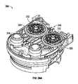
図15は、例示的な器具ドライバを示す。ロボットアームの遠位端部に位置付けられる器具ドライバ62は、駆動シャフト64を介して医療用器具に制御されたトルクを提供するために平行軸線を伴って配置された1つ以上の駆動ユニット63を含む。各駆動ユニット63は、器具と相互作用するための個々の駆動シャフト64と、モータシャフトの回転を所望のトルクに変換するためのギアヘッド65と、駆動トルクを生成するためのモータ66と、モータシャフトの速度を測定して制御回路にフィードバックを提供するエンコーダ67と、制御信号を受信して駆動ユニットを作動させるための制御回路68と、を含む。各駆動ユニット63は、独立して制御され電動化され、器具ドライバ62は、複数(例えば図15に示すように4つ)の独立した駆動出力を医療用器具に提供することができる。動作中、制御回路68は、制御信号を受信し、モータ66にモータ信号を送信し、エンコーダ67によって測定された結果として得られたモータ速度を所望の速度と比較し、モータ信号を変調して所望のトルクを生成する。 FIG. 15 shows an exemplary instrument driver. An
無菌環境を必要とする処置のために、ロボットシステムは、器具ドライバと医療用器具との間に位置する、滅菌ドレープに接続された滅菌アダプタなどの駆動インターフェースを組み込んでもよい。滅菌アダプタの主な目的は、器具ドライバの駆動シャフトから器具の駆動入力部に角度運動を伝達する一方で、駆動シャフトと駆動入力部との間の物理的分離、したがって無菌性を維持することである。したがって、例示的な滅菌アダプタは、器具ドライバの駆動シャフトと嵌合されることが意図された一連の回転入力部及び出力部と、器具に対する駆動入力部と、を含み得る。滅菌アダプタに接続される滅菌ドレープは、透明又は半透明プラスチックなどの薄い可撓性材料で構成され、器具ドライバ、ロボットアーム、及び(カートベースのシステムにおける)カート又は(テーブルベースのシステムにおける)テーブルなどの資本設備を覆うように設計される。ドレープの使用により、滅菌を必要としない領域(すなわち、非滅菌野)に依然として位置させたままで、資本設備を患者に近接して位置付けることが可能となる。滅菌ドレープの反対側では、医療用器具は、滅菌を必要とする領域(すなわち、滅菌野)において患者とインターフェースしてもよい。 For procedures requiring a sterile environment, the robotic system may incorporate a drive interface, such as a sterile adapter connected to a sterile drape, positioned between the instrument driver and the medical instrument. The primary purpose of the sterile adapter is to transmit angular motion from the drive shaft of the instrument driver to the drive input of the instrument while maintaining physical separation and therefore sterility between the drive shaft and the drive input. be. Accordingly, an exemplary sterile adapter may include a series of rotary inputs and outputs intended to mate with the drive shaft of an instrument driver and a drive input to the instrument. A sterile drape, which is connected to a sterile adapter, is constructed of a thin, flexible material, such as transparent or translucent plastic, and is attached to the instrument driver, robotic arm, and cart (in cart-based systems) or table (in table-based systems). Designed to cover capital equipment such as The use of drapes allows capital equipment to be positioned in close proximity to the patient while still positioned in areas where sterilization is not required (ie, non-sterile fields). On the opposite side of the sterile drape, medical instruments may interface with the patient in areas requiring sterilization (ie, the sterile field).
D.医療用器具
図16は、ペアの器具ドライバを備えた例示的な医療用器具を示す。ロボットシステムと共に使用するために設計された他の器具と同様に、医療用器具70は、細長いシャフト71(又は細長い本体)及び器具基部72を含む。医師による手動相互作用が意図されているその設計により「器具ハンドル」とも呼ばれる器具基部72は、一般に、ロボットアーム76の遠位端部において器具ドライバ75上の駆動インターフェースを通って延びる駆動出力部74と嵌合するように設計された、回転可能な駆動入力部73、例えば、レセプタクル、プーリー、又はスプールを含んでもよい。物理的に接続、ラッチ、及び/又は連結される場合、器具基部72の嵌合された駆動入力部73は、器具ドライバ75における駆動出力部74と回転軸線を共有して、駆動出力部74から駆動入力部73へのトルクの伝達を可能とすることができる。いくつかの実施形態では、駆動出力部74は、駆動入力部73上のレセプタクルと嵌合するように設計されたスプラインを含んでもよい。D. Medical Instruments FIG. 16 shows an exemplary medical instrument with a pair of instrument drivers. As with other instruments designed for use with robotic systems, medical instrument 70 includes elongated shaft 71 (or elongated body) and
細長いシャフト71は、例えば、内視鏡におけるような解剖学的開口部若しくは管腔、又は腹腔鏡検査におけるような低侵襲性切開部のいずれかを通して送達されるように設計される。細長いシャフト71は、可撓性(例えば、内視鏡と同様の特性を有する)若しくは剛性(例えば、腹腔鏡と同様の特性を有する)のいずれかであってもよく、又は可撓性部分及び剛性部分の両方のカスタマイズされた組み合わせを含んでもよい。腹腔鏡検査のために設計される場合、剛性の細長いシャフトの遠位端部は、少なくとも1つの自由度を有するクレビスから形成された接合されたリストから延在するエンドエフェクタ、及び駆動入力部が器具ドライバ75の駆動出力部74から受け取ったトルクに応答して回転するときに、腱からの力に基づいて作動され得る、例えば、把持具又ははさみなどの外科用ツール又は医療用器具に接続することができる。内視鏡検査のために設計される場合、可撓性の細長いシャフトの遠位端部は、器具ドライバ75の駆動出力部74から受け取ったトルクに基づいて関節運動及び屈曲され得る操縦可能又は制御可能な屈曲部を含んでもよい。 Elongated shaft 71 is designed to be delivered through either an anatomical opening or lumen, such as in an endoscope, or a minimally invasive incision, such as in laparoscopy, for example. Elongated shaft 71 may be either flexible (eg, having properties similar to an endoscope) or rigid (eg, having properties similar to a laparoscope), or a flexible portion and a It may also include a customized combination of both rigid sections. When designed for laparoscopy, the distal end of the rigid elongate shaft includes an end effector extending from an articulated wrist formed from a clevis having at least one degree of freedom, and a drive input. For example, it connects to a surgical tool or medical instrument, such as a grasper or scissors, that can be actuated based on force from a tendon as it rotates in response to torque received from the
器具ドライバ75からのトルクは、細長いシャフト71に沿った腱を使用して細長いシャフト71の下流に伝達される。プルワイヤなどのこれらの個々の腱は、器具ハンドル72内の個々の駆動入力部73に個別に固定されてもよい。器具ハンドル72から、腱は、細長いシャフト71に沿って1つ以上のプルルーメン(pull lumens)の下方に向けられ、細長いシャフト71の遠位部分、又は細長いシャフトの遠位部分のリスト部に固定される。腹腔鏡、内視鏡、又はハイブリッド処置などの外科処置中、これらの腱は、リスト、把持具、又ははさみなどの遠位に装着されたエンドエフェクタに連結されてもよい。このような構成の下で、駆動入力部73に及ぼされるトルクは、腱に張力を伝達し、それによってエンドエフェクタを何らかの方法で作動させる。いくつかの実施形態では、外科処置中に、腱は、接合部を軸線の周りで回転させることができるが、それによってエンドエフェクタを一方向又は別の方向に移動させる。代替的には、腱は、細長いシャフト71の遠位端部で把持具の1つ以上のジョーに接続されてもよく、腱からの張力によって把持具は閉鎖される。 Torque from the instrument driver 75 is transmitted down the elongated shaft 71 using tendons along the elongated shaft 71 . These individual tendons, such as pull wires, may be individually secured to
内視鏡検査では、腱は、接着剤、制御リング、又は他の機械的固定を介して、細長いシャフト71に沿って(例えば、遠位端部に)位置付けられている屈曲部又は関節運動部に連結されてもよい。屈曲部の遠位端部に固定的に取り付けられる場合、駆動入力部73に及ぼされるトルクは、腱の下流に伝達され、より軟質の屈曲部(関節運動可能部又は関節運動可能領域と呼ばれることがある)を屈曲又は関節運動させる。非屈曲部分に沿って、個々の腱を内視鏡シャフトの壁に沿って(又は内側に)向く個々のプルルーメンを螺旋状又は渦巻状にして、プルワイヤにおける張力からもたらされる半径方向の力の釣り合いをとることが有利であり得る。螺旋の角度及び/又はそれらの間の間隔は、特定の目的のために変更又は設計することができ、よりきつい螺旋は負荷力の下でより少ないシャフト圧縮を示し、一方、より少ない量の螺旋は負荷力の下でより大きなシャフト圧縮をもたらすが、屈曲を制限する。スペクトルのもう一方の端部では、プルルーメンは、細長いシャフト71の長手方向軸線に平行に方向付けられて、所望の屈曲部又は関節運動可能部における制御された関節運動を可能にしてもよい。 In endoscopy, the tendon is positioned along the elongated shaft 71 (e.g., at the distal end) via an adhesive, control ring, or other mechanical fixation at a flexure or articulation. may be connected to When fixedly attached to the distal end of the flexure, the torque exerted on the
内視鏡検査では、細長いシャフト71は、ロボット処置を支援するいくつかの構成要素を収容する。シャフト71は、シャフト71の遠位端部における手術領域に対して外科用ツール(又は医療用器具)を展開する、灌注する、及び/又は吸引するためのワーキングチャネルを含んでもよい。シャフト71は、遠位先端部の光学アセンブリに信号を伝送するためのワイヤ及び/又は光ファイバも収容してもよく、これは光学カメラを含んでもよい。シャフト71はまた、発光ダイオードなどの近位に位置する光源からシャフト71の遠位端部に光を搬送するための光ファイバを収容してもよい。 In endoscopy, elongated shaft 71 houses several components that assist in robotic procedures. Shaft 71 may include a working channel for deploying, irrigating, and/or aspirating surgical tools (or medical instruments) to the surgical area at the distal end of shaft 71 . Shaft 71 may also contain wires and/or optical fibers for transmitting signals to the optical assembly of the distal tip, which may include an optical camera. Shaft 71 may also contain optical fibers for carrying light from a proximally located light source, such as a light emitting diode, to the distal end of shaft 71 .
器具70の遠位端部では、遠位先端部は、診断及び/又は治療、灌注、及び吸引のためにツールを手術部位に送達するためのワーキングチャネルの開口部を含んでもよい。遠位先端部はまた、内部解剖学的空間の画像をキャプチャするために、ファイバスコープ又はデジタルカメラなどのカメラのためのポートを含んでもよい。関連して、遠位先端部はまた、カメラを使用する場合に解剖学的空間を照明するための光源用のポートを含んでもよい。 At the distal end of instrument 70, the distal tip may include working channel openings for delivering tools to the surgical site for diagnosis and/or therapy, irrigation, and aspiration. The distal tip may also include a port for a camera, such as a fiberscope or digital camera, to capture images of the internal anatomical space. Relatedly, the distal tip may also include a port for a light source to illuminate the anatomical space when using a camera.
図16の例では、駆動シャフト軸線、すなわち駆動入力軸線は、細長いシャフト71の軸線に直交する。しかしながら、この配置は、細長いシャフト71の旋回能力を複雑にする。駆動入力部73を静止させながら、細長いシャフト71をその軸線に沿って旋回させることにより、腱が駆動入力部73から延在し、細長いシャフト71内のプルルーメンに入るときに、腱の望ましくない絡まりをもたらす。そのような腱の結果としての絡まりは、内視鏡処置中の可撓性の細長いシャフト71の動きを予測することを意図した制御アルゴリズムを混乱させる可能性がある。 In the example of FIG. 16, the drive shaft axis, ie the drive input axis, is orthogonal to the axis of elongated shaft 71 . However, this arrangement complicates the pivoting ability of elongated shaft 71 . Pivoting elongated shaft 71 along its axis while
図17は、駆動ユニットの軸線が器具の細長いシャフトの軸線に平行である、器具ドライバ及び器具の代替的な設計を示す。示されるように、円形の器具ドライバ80は、ロボットアーム82の端部において平行に位置合わせされた駆動出力部81を備える4つの駆動ユニットを含む。駆動ユニット及びそれらのそれぞれの駆動出力部81は、アセンブリ83内の駆動ユニットのうちの1つによって駆動される器具ドライバ80の回転アセンブリ83内に収容される。回転駆動ユニットによって提供されるトルクに応答して、回転アセンブリ83は、回転アセンブリ83を器具ドライバ80の非回転部分84に接続する円形ベアリングに沿って回転する。電力及び制御信号は、ブラシ付きスリップリング接続(図示せず)による回転を通して維持され得る電気接点を介して、器具ドライバ80の非回転部分84から回転アセンブリ83に伝達されてもよい。他の実施形態では、回転アセンブリ83は、非回転可能部分84に一体化され、したがって他の駆動ユニットと平行ではない別個の駆動ユニットに応答してもよい。回転機構83は、器具ドライバ80が、器具ドライバ軸線85周りの単一ユニットとして、駆動ユニット及びそれらのそれぞれの駆動出力部81を回転させることを可能にする。 Figure 17 shows an alternative design of the instrument driver and instrument in which the axis of the drive unit is parallel to the axis of the elongated shaft of the instrument. As shown,
先に開示した実施形態と同様に、器具86は、細長いシャフト部分88と、器具ドライバ80内の駆動出力部81を受け入れるように構成された複数の駆動入力部89(レセプタクル、プーリー、及びスプールなど)を含む器具基部87(説明目的のために透明な外部スキンで示される)と、を含んでもよい。先の開示された実施形態とは異なり、器具シャフト88は、器具基部87の中心から延在し、軸線は駆動入力部89の軸線に実質的に平行であり、図16の設計にあるように直交してはいない。 As with the previously disclosed embodiments, the
器具ドライバ80の回転アセンブリ83に連結されると、器具基部87及び器具シャフト88を含む医療用器具86は、器具ドライバ軸線85を中心にして回転アセンブリ83と一緒に回転する。器具シャフト88は器具基部87の中心に位置付けられているため、器具シャフト88は、取り付けられたときに器具ドライバ軸線85と同軸である。したがって、回転アセンブリ83の回転により、器具シャフト88は、それ自体の長手方向軸線を中心に回転する。更に、器具基部87が器具シャフト88と共に回転すると、器具基部87内の駆動入力部89に接続された任意の腱は、回転中に絡まらない。したがって、駆動出力部81、駆動入力部89、及び器具シャフト88の軸線の平行性は、制御腱を絡めることなくシャフト回転を可能にする。 When coupled to rotating
図18は、いくつかの実施形態による、器具ベースの挿入アーキテクチャを有する器具150を示す。器具150は、上述の器具ドライバのいずれかに連結することができる。器具150は、細長いシャフト152と、シャフト152に接続されたエンドエフェクタ162と、シャフト152に連結されたハンドル170と、を含む。細長いシャフト152は、近位部分154及び遠位部分156を有する管状部材を含む。細長いシャフト152は、その外側表面に沿った1つ以上のチャネル又は溝158を含む。溝158は、1つ以上のワイヤ又はケーブル180をそれを通して受け入れるように構成されている。したがって、1つ以上のケーブル180は、細長いシャフト152の外側表面に沿って延びる。他の実施形態では、ケーブル180は、細長いシャフト152を通って延びることもできる。ケーブル180のうちの1つ以上の操作(例えば、器具ドライバを介して)により、エンドエフェクタ162の作動がもたらされる。 FIG. 18 shows an
器具基部とも称され得る器具ハンドル170は、一般に、器具ドライバの取り付け面上で1つ以上のトルクカプラと往復嵌合するように設計された1つ以上の機械的入力部174、例えばレセプタクル、プーリー又はスプールを有する取り付けインターフェース172を含むことができる。 The instrument handle 170, which may also be referred to as an instrument base, generally includes one or more
いくつかの実施形態では、器具150は、細長いシャフト152がハンドル170に対して並進することを可能にする一連のプーリー又はケーブルを含む。換言すれば、器具150自体は器具の挿入に適応する器具ベースの挿入アーキテクチャを含み、それによって器具150の挿入を提供するためにロボットアームへの依存を最小化する。他の実施形態では、ロボットアームは、器具の挿入に大きく関与することができる。 In some embodiments,
E.コントローラ
本明細書に記載の任意のロボットシステムは、ロボットアームに取り付けられた器具を操作するための入力デバイス又はコントローラを含むことができる。いくつかの実施形態では、コントローラは、器具と連結(例えば、通信的に、電子的に、電気的に、無線的に、及び/又は機械的に)することができ、それによりコントローラの操作は、例えば、マスタースレーブ制御を介して、器具の対応する操作を引き起こす。E. Controller Any robotic system described herein can include an input device or controller for manipulating instruments attached to the robotic arm. In some embodiments, the controller can be coupled (e.g., communicatively, electronically, electrically, wirelessly, and/or mechanically) with the instrument such that operation of the controller is , for example via master-slave control, causing corresponding manipulation of the instrument.
図19は、コントローラ182の実施形態の斜視図である。本実施形態では、コントローラ182は、インピーダンス制御及びアドミタンス制御の両方を有することができるハイブリッドコントローラを含む。他の実施形態では、コントローラ182は、インピーダンス又は受動的制御だけを利用することができる。他の実施形態では、コントローラ182は、アドミタンス制御だけを利用することができる。ハイブリッドコントローラであることにより、コントローラ182は、有利には、使用中、より低い知覚慣性を有することができる。 FIG. 19 is a perspective view of an embodiment of
図示される実施形態では、コントローラ182は、2つの医療用器具の操作を可能にするように構成され、2つのハンドル184を含む。ハンドル184の各々は、ジンバル186に接続されている。各ジンバル186は、位置決めプラットフォーム188に接続されている。 In the illustrated embodiment,
図19に示されるように、各位置決めプラットフォーム188は、プリズム接合部196によってカラム194に連結された選択的コンプライアンスアセンブリロボットアーム(selective compliance assembly robot arm、SCARA)198を含む。プリズム接合部196は、(例えば、レール197に沿って)カラム194に沿って並進して、ハンドル184の各々がz方向に並進され、第1の自由度を提供するように構成されている。SCARA198は、x-y平面におけるハンドル184の動作を可能にし、2つの追加的な自由度を提供するように構成されている。 As shown in FIG. 19, each
いくつかの実施形態では、1つ以上のロードセルがコントローラ内に位置付けられる。例えば、いくつかの実施形態では、ロードセル(図示せず)は、ジンバル186の各々の本体内に位置付けられる。ロードセルを設けることによって、コントローラ182の一部分は、アドミタンス制御下で動作することができ、それによって、使用中にコントローラの知覚慣性を有利に低減する。いくつかの実施形態では、位置決めプラットフォーム188はアドミタンス制御用に構成され、一方、ジンバル186はインピーダンス制御用に構成されている。他の実施形態では、ジンバル186はアドミタンス制御用に構成され、位置決めプラットフォーム188はインピーダンス制御用に構成されている。したがって、いくつかの実施形態では、位置決めプラットフォーム188の並進又は位置自由度は、アドミタンス制御に依存することができ、一方、ジンバル186の回転自由度はインピーダンス制御に依存する。 In some embodiments, one or more load cells are positioned within the controller. For example, in some embodiments, a load cell (not shown) is positioned within the body of each
F.ナビゲーション及び制御
従来の内視鏡検査は、オペレータである医師に腔内誘導を提供するために、蛍光透視法(例えば、Cアームを通して送達され得るような)、及び他の形態の放射線ベースの撮像モダリティの使用を伴うことがある。対照的に、本開示によって企図されるロボットシステムは、放射線への医師の暴露を低減し、手術室内の機器の量を低減するために、非放射線ベースのナビゲーション及び位置特定手段を提供することができる。本明細書で使用するとき、用語「位置特定」は、基準座標系内のオブジェクトの位置を判定及び/又は監視することを指すことがある。術前マッピング、コンピュータビジョン、リアルタイムEM追跡、及びロボットコマンドデータなどの技術は、放射線を含まない動作環境を達成するために個別に又は組み合わせて使用されてもよい。放射線ベースの撮像モダリティが依然として使用されるその他の場合、術前マッピング、コンピュータビジョン、リアルタイムEM追跡、及びロボットコマンドデータは、放射線ベースの撮像モダリティによってのみ取得される情報を改善するために、個別に又は組み合わせて使用されてもよい。F. Navigation and Control Conventional endoscopy uses fluoroscopy (such as can be delivered through a C-arm) and other forms of radiation-based imaging to provide intraluminal guidance to the operator physician. May involve the use of modalities. In contrast, robotic systems contemplated by the present disclosure can provide non-radiation based navigation and localization means to reduce physician exposure to radiation and reduce the amount of equipment in the operating room. can. As used herein, the term "localization" may refer to determining and/or monitoring the position of an object within a frame of reference. Technologies such as preoperative mapping, computer vision, real-time EM tracking, and robotic command data may be used individually or in combination to achieve a radiation-free operating environment. In other cases where radiation-based imaging modalities are still used, pre-operative mapping, computer vision, real-time EM tracking, and robotic command data may be used separately to improve the information obtained only by radiation-based imaging modalities. or may be used in combination.
図20は、例示的な実施形態にかかる、器具の場所など、ロボットシステムの1つ以上の要素の場所を推定する位置特定システム90を示すブロック図である。位置特定システム90は、1つ以上の命令を実行するように構成されている1つ以上のコンピュータデバイスの組であってもよい。コンピュータデバイスは、上で考察された1つ以上の構成要素内のプロセッサ(又は複数のプロセッサ)及びコンピュータ可読メモリによって具現化されてもよい。例として、限定するものではないが、コンピュータデバイスは、図1に示されるタワー30内にあっても、図1~図4に示されるカート11内にあっても、図5~図14に示されるベッド内にあってもよい。 FIG. 20 is a block diagram illustrating a
図20に示されるように、位置特定システム90は、入力データ91~94を処理して医療用器具の遠位先端部の場所データ96を生成する位置特定モジュール95を含んでもよい。場所データ96は、基準系に対する器具の遠位端部の場所及び/又は向きを表すデータ又は論理であってもよい。基準系は、患者の解剖学的構造、又はEM場発生器(EM場発生器についての以下の考察を参照)などの既知の物体に対する基準系とすることができる。 As shown in FIG. 20, the
ここで、様々な入力データ91~94についてより詳細に説明する。位置特定モジュール95は、術前マッピングを使用してモデルデータ91を生成することができる。術前マッピングは、低用量CTスキャンの群を使用して達成することができる。術前CTスキャンは、例えば、患者の内部解剖学的構造の断面図の「スライス」として可視化される三次元画像へと再構成される。全体として分析される場合、患者の肺網などの患者の解剖学的構造の解剖学的空腔、空間、及び構造のための画像ベースのモデルが生成され得る。中心線形状(center-line geometry)などの手法をCT画像から決定及び近似して、モデルデータ91(術前CTスキャンのみを使用して生成された場合は「術前モデルデータ」とも称される)と称される患者の解剖学的構造の三次元ボリュームを作成することができる。中心線形状の使用は、米国特許出願第14/523,760号で考察されており、その内容はその全体が本明細書に組み込まれる。ネットワーク位相モデルもまた、CT画像から導出されてもよく、気管支鏡検査に特に適している。 The various input data 91-94 will now be described in more detail.
いくつかの実施形態では、器具はカメラを装備して、視覚データ(又は画像データ)92を位置特定モジュール95に提供してもよい。位置特定モジュール95は、視覚データ92を処理して、1つ以上の視覚ベースの(又は画像ベースの)位置追跡モジュール又は機能を有効にしてもよい。例えば、術前モデルデータ91は、医療用器具(例えば、内視鏡又は内視鏡のワーキングチャネルを通って前進する器具)のコンピュータビジョンベースの追跡を可能にするために、視覚データ92と共に使用されてもよい。例えば、術前モデルデータ91を使用して、ロボットシステムは、内視鏡の予想される移動経路に基づいて、モデルから、予測される内視鏡画像のライブラリを生成することができ、各画像はモデル内の場所にリンクされる。手術中に、このライブラリは、カメラ(例えば、内視鏡の遠位端部でのカメラ)でキャプチャされたリアルタイム画像を画像ライブラリ内のものと比較して、位置特定を支援するために、ロボットシステムによって参照することができる。 In some embodiments, the instrument may be equipped with a camera to provide visual data (or image data) 92 to
他のコンピュータビジョンベースの追跡技術は、追跡機能を使用して、カメラ、したがって内視鏡の動作を決定する。位置特定モジュール95のいくつかの特徴は、解剖学的管腔に対応する術前モデルデータ91内の円形幾何学形状を特定し、どの解剖学的管腔が選択されたか、並びにカメラの相対的な回転及び/又は並進運動を決定するために、それらの幾何学的形状の変化を追跡してもよい。位相マップの使用は、視覚ベースのアルゴリズム又は技術を更に向上させることがある。 Other computer vision-based tracking techniques use tracking capabilities to determine the motion of the camera, and thus the endoscope. Several features of the
光学フロー、別のコンピュータビジョンベースの技術は、カメラの移動を推測するために、視覚データ92内のビデオシーケンス内の画像ピクセルの変位及び並進を分析してもよい。光学フロー技術の例としては、動作検出、オブジェクトセグメンテーション計算、輝度、動作補償符号化、立体視差測定などを挙げることができる。複数の反復にわたり多数のフレームを比較することにより、カメラ(及びしたがって内視鏡)の移動及び位置を判定することができる。 Optical Flow, another computer vision-based technique, may analyze displacements and translations of image pixels within a video sequence within
位置特定モジュール95は、リアルタイムEM追跡及びEMデータ93を使用して、術前モデルによって表される患者の解剖学的構造に登録され得るグローバル座標系における内視鏡のリアルタイム位置を生成してもよい。EM追跡では、医療用器具(例えば、内視鏡ツール)内の1つ以上の位置及び向きに埋め込まれた1つ以上のセンサコイルを含むEMセンサ(又はトラッカー)は、既知の位置に位置付けられた1つ以上の静的EM場発生器によって生成されるEM場の変動を測定する。EMセンサによって検出された位置情報は、EMデータ93として記憶される。EM場発生器(又は送信機)は、埋め込まれたセンサが検出し得る低強度磁場を生成するために、患者に近接して配置することができる。磁場はEMセンサのセンサコイル内に小さな電流を誘導し、EMセンサとEM場発生器との間の距離及び角度を判定するためにこの電流が分析され得る。これらの距離及び向きは、患者の解剖学的構造の術前モデル内の位置と座標系内の単一の場所を位置合わせする幾何学的変換を判定するために、患者の解剖学的構造(例えば、術前モデル)に術中「登録」され得る。一旦登録されると、医療用器具の1つ以上の位置(例えば、内視鏡の遠位先端部)に埋め込まれたEMトラッカは、患者の解剖学的構造を通る医療用器具の進行のリアルタイム表示を提供することができる。 A
ロボットコマンド及び運動学データ94はまた、ロボットシステムのための場所データ96を提供するために、位置特定モジュール95によって使用されてもよい。関節運動コマンドから生じるデバイスピッチ及びヨーは、術前較正中に判定され得る。術中、これらの較正測定値は、既知の挿入深度情報と組み合わせて使用されて、器具の位置を推定し得る。代替的には、これらの計算は、EM、視覚、及び/又は位相モデリングと組み合わせて分析して、ネットワーク内の医療用器具の位置を推定し得る。 Robotic command and
図20が示すように、多くの他の入力データは、位置特定モジュール95によって使用することができる。例えば、図20には示していないが、形状感知ファイバを利用する器具は、位置特定モジュール95が器具の場所及び形状を判定するために使用し得る形状データを提供することができる。 Many other input data can be used by the
位置特定モジュール95は、入力データ91~94を組み合わせて使用することができる。場合によっては、このような組み合わせは、位置特定モジュール95が入力データ91~94の各々から判定された場所に信頼重み(confidence weight)を割り当てる確率的アプローチを使用し得る。したがって、EMデータが信頼でき得ない場合(EM干渉が存在する場合など)、EMデータ93によって判定された場所の信頼性を低下させることになり、位置特定モジュール95は、視覚データ92並びに/又はロボットコマンド及び運動学データ94により重く依存してもよい。 The
上で考察されるように、本明細書で考察されるロボットシステムは、上述の技術のうちの1つ以上の組み合わせを組み込むように設計することができる。タワー、ベッド、及び/又はカートをベースとするロボットシステムのコンピュータベースの制御システムは、例えば、永続的な磁気記憶ドライブ、ソリッドステートドライブなどの非一時的コンピュータ可読記憶媒体内に、コンピュータプログラム命令を記憶してもよく、コンピュータプログラム命令は、実行されると、システムに、センサデータ及びユーザーコマンドを受信及び分析させ、システム全体の制御信号を生成させ、グローバル座標系内の器具の位置、解剖学的マップなどのナビゲーション及び位置特定データを表示させる。 As discussed above, the robotic systems discussed herein can be designed to incorporate a combination of one or more of the techniques described above. Computer-based control systems for tower-, bed-, and/or cart-based robotic systems store computer program instructions in non-transitory computer-readable storage media, such as, for example, persistent magnetic storage drives, solid-state drives, and the like. may be stored, and computer program instructions, when executed, cause the system to receive and analyze sensor data and user commands, generate system-wide control signals, determine the position of the instrument within the global coordinate system, the anatomy Display navigation and location data such as target maps.
2.ロボット医療用システムのための軸方向運動駆動装置
このセクションは、医療用器具のシャフトの軸方向運動を駆動するように構成された駆動装置に関する。駆動装置は、例えば、医療処置中に医療用器具のシャフトを患者に挿入するために使用することができる。医療用器具としては、例えば、尿管鏡、胃カメラ、気管支鏡、その他の内視鏡や腹腔鏡などを挙げることができる。医療用器具のシャフトは、患者に挿入するように構成することができる。シャフトは、例えば、細長いシャフト、可撓性シャフト、及び/又は関節運動可能なシャフトとすることができる。軸方向運動は、シャフトの長手方向軸線に沿った方向における医療用器具のシャフトの動きを含むことができる。例えば、軸方向運動は、患者の中に、及び/若しくは患者の外に、並びに/又は駆動装置に対して、シャフトを挿入及び/又は後退させることを含み得る。2. AXIAL MOTION DRIVE FOR ROBOTICAL MEDICAL SYSTEMS This section relates to drives configured to drive axial motion of a shaft of a medical instrument. The drive can be used, for example, to insert the shaft of a medical instrument into a patient during a medical procedure. Examples of medical instruments include ureteroscopes, gastroscopes, bronchoscopes, other endoscopes and laparoscopes. A shaft of the medical device can be configured for insertion into a patient. The shaft can be, for example, an elongate shaft, a flexible shaft, and/or an articulatable shaft. Axial motion can include movement of the shaft of the medical device in a direction along the longitudinal axis of the shaft. For example, axial motion can include inserting and/or retracting a shaft into and/or out of the patient and/or relative to the drive.
本駆動装置は、図1~図20を参照しながら上述したロボット医療用システム、以下に説明するロボット医療用システム、及び別のロボット医療用システムを含む、ロボット医療用システムにおいて使用することができる。いくつかの実施形態では、駆動装置は、例えば、尿管鏡検査、胃鏡検査、気管支鏡検査などの様々な医療処置を行うために使用することができる。いくつかの実施形態では、駆動装置は、上述したように、ロボットアーム、器具駆動機構、及び/又はアダプタに連結するように構成された再利用可能なツール、リポーザブルツール、又は使い捨てのツールとすることができる。いくつかの実施形態では、駆動装置は、別の医療用器具又はツールのシャフトを装填してその軸方向運動を駆動することに関連する様々な機能を容易にするために、歯車装置アセンブリ又は機構アセンブリを含むことができる。 The drive apparatus can be used in robotic medical systems, including the robotic medical systems described above with reference to FIGS. 1-20, the robotic medical systems described below, and other robotic medical systems. . In some embodiments, the drive device can be used to perform various medical procedures such as, for example, ureteroscopy, gastroscopy, bronchoscopy, and the like. In some embodiments, the drive is a reusable, reposable, or disposable tool configured to couple to a robotic arm, instrument drive mechanism, and/or adapter, as described above. can do. In some embodiments, the drive is a gearing assembly or mechanism to facilitate various functions associated with loading the shaft of another medical instrument or tool and driving its axial motion. Can include assembly.
後から更に詳しく説明するように、駆動装置(駆動アセンブリとも呼ばれる)は、駆動装置を通る医療用器具のシャフトを引っ張る、又は押すように構成することができる。駆動装置は、シャフトの長さに沿った位置でシャフトと係合することができる。いくつかの実施形態では、駆動装置は、一組の対向するローラ(「フィードローラ」とも呼ばれる)を含み、これらのローラは、シャフトと係合し、回転するときに軸方向運動(例えば挿入及び/又は後退)を駆動する。いくつかの実施形態では、駆動装置は、シャフトの軸方向運動を駆動するための、トレッドシステム、ラックアンドピニオンシステム、又は他の機構(例えば直線機構)を含むことができる。いくつかの実施形態では、駆動装置は、シャフトの挿入及び後退中に1つ以上のサービスループを生成して利用するように構成することができる。本明細書では、サービスループとは、(シャフトが延びる起点となる)器具基部と駆動装置との間の器具のシャフトの長さであって、器具基部と駆動装置との間の距離よりも長い長さを指すことができる。したがってサービスループは、器具基部と駆動装置との間にたるみを提供することができる。後から更に詳しく説明する図22には、サービスループ226の一例を示してある。 As will be described in more detail below, the drive (also called drive assembly) can be configured to pull or push the shaft of the medical instrument through the drive. The drive can engage the shaft at locations along the length of the shaft. In some embodiments, the drive includes a set of opposed rollers (also called "feed rollers") that engage the shaft and provide axial motion (e.g., insertion and / or reverse). In some embodiments, the drive may include a tread system, rack and pinion system, or other mechanism (eg, linear mechanism) for driving axial motion of the shaft. In some embodiments, the drive can be configured to create and utilize one or more service loops during shaft insertion and retraction. As used herein, the service loop is the length of the instrument shaft between the instrument base (where the shaft begins to extend) and the drive that is greater than the distance between the instrument base and the drive. You can point to the length. The service loop can thus provide slack between the instrument base and the drive. An example of a
一般に、本明細書に記載されている駆動装置並びに関連するロボットシステム及び方法は、他の装置及びシステムに優る1つ以上の利点を提供することができる。いくつかのケースでは、本明細書に記載されている駆動装置は、他のロボットシステムと比較して、医療用器具のシャフトの挿入及び/又は後退を、増大した速度又はより高い速度で可能にすることができる。例えば、いくつかのロボットシステムでは、ロボット制御される尿管鏡を患者に挿入及び/又は患者から後退させることのできる速度(例えば尿道口から腎盂への挿入)は、ロボットアームの直線速度によって制限される。このようなシステムでは、挿入及び後退の速度は、ロボットアームがどれだけ速く動き得るかによって制限される。本セクションで説明する駆動装置及び関連するロボットシステムは、いくつかの実施形態では、増大した挿入速度及び/又は後退速度を可能にすることができる。いくつかの実施形態では、本駆動装置は、システム内のロボットアームの直線速度よりも大きい挿入速度及び/又は後退速度を可能にすることができる。挿入及び/又は後退速度を増大させることにより、いくつかの医療処置を行うために必要な全体の時間を大幅に減少させることができ、これにより、例えば患者の転帰を改善することができる。例えば、尿管鏡検査の場合、腎臓結石や腎臓結石片をすべて捕捉して除去するために、尿管鏡を腎臓に何度も挿入して後退させることがある。したがって、挿入速度及び/又は後退速度を高めることにより、処置に必要な総時間が累積的に短縮され、コストが減少し、患者の転帰が改善される。 In general, the drives and associated robotic systems and methods described herein may provide one or more advantages over other devices and systems. In some cases, the drives described herein enable insertion and/or retraction of shafts of medical instruments at increased or higher speeds compared to other robotic systems. can do. For example, in some robotic systems, the speed at which a robotically controlled ureteroscope can be inserted into and/or withdrawn from a patient (e.g., from the urethral meatus to the renal pelvis) is limited by the linear velocity of the robotic arm. be done. In such systems, the speed of insertion and retraction is limited by how fast the robotic arm can move. The drives and associated robotic systems described in this section can enable increased insertion and/or retraction speeds in some embodiments. In some embodiments, the drive can allow insertion and/or retraction velocities that are greater than the linear velocity of the robotic arm in the system. By increasing the rate of insertion and/or withdrawal, the overall time required to perform some medical procedures can be significantly reduced, which can improve patient outcomes, for example. For example, in the case of ureteroscopy, the ureteroscope may be inserted and retracted multiple times into the kidney to capture and remove all kidney stones and debris. Therefore, increasing the rate of insertion and/or withdrawal speeds cumulatively reduces the total time required for the procedure, reduces costs, and improves patient outcomes.
同様に、いくつかの例では、本明細書に記載されている駆動装置及び関連するロボットシステムは、いくつかの他のロボットシステムと比較して、改善された挿入深さ(又はストローク長)を提供することができる。いくつかのロボットアームベースのシステムでは、挿入深さ(ストローク長)は、ロボットアームのストローク長に制限され得る。この挿入深さは、大きな挿入深さ又は挿入範囲を必要とし得る胃鏡検査などの一部の処置の場合に不十分なことがある。更に、処置中にロボットアームをその可能なストローク長全体にわたり動かすことによって、運動学的な課題が生じることがあり、アームを他の物体に衝突させる危険性があり、これは望ましくなく危険であり得る。後から説明するように、本出願の駆動装置は、いくつかの実施形態では、ロボットアームのストローク長を越えて挿入深さを増加させることができる。 Similarly, in some examples, the drives and associated robotic systems described herein have improved insertion depth (or stroke length) compared to some other robotic systems. can provide. In some robotic arm-based systems, the insertion depth (stroke length) may be limited to the stroke length of the robotic arm. This insertion depth may be insufficient for some procedures, such as gastroscopy, which may require a large insertion depth or range. Furthermore, moving the robotic arm through its entire possible stroke length during a procedure can create kinematic challenges and risk colliding the arm with other objects, which is undesirable and dangerous. obtain. As will be explained later, the drives of the present application can, in some embodiments, increase the depth of insertion beyond the stroke length of the robotic arm.
別の例として、本明細書に記載されている駆動装置及び関連するロボットシステムは、挿入中のシャフトの座屈を低減又は防止することができる。シャフトは一般的に柔軟であるため、医療用器具の後方(例えば、器具ハンドル又は器具基部)から挿入を駆動するときに座屈が発生することがある。このような座屈は、ロボットアームが、比較的長く、柔軟で、支持されていないシャフトの長さの端部に力を加えるために起こり得る。本駆動装置は、いくつかの実施形態では、シャフトが患者に挿入されるポイント(アクセスポイントとも呼ばれる)に近接する位置においてシャフトの挿入を駆動するので、座屈を低減又は排除することができる。本駆動装置は、アクセスポイントから比較的離れた位置にあり得るシャフトの近位端部ではなく、アクセスポイントに近い位置で医療用器具のシャフトに作用する挿入力を提供することができる。シャフトの長さに沿って、挿入ポイントの近位の位置で駆動装置によって力を加えることにより、本明細書に記載されている駆動装置は、シャフトの座屈を低減又は排除することができる。 As another example, the drives and associated robotic systems described herein can reduce or prevent shaft buckling during insertion. Since the shaft is generally flexible, buckling can occur when driving insertion from the back of the medical instrument (eg, instrument handle or instrument base). Such buckling can occur because the robotic arm exerts a force on the end of the length of the relatively long, flexible, unsupported shaft. The driver, in some embodiments, drives insertion of the shaft at a location proximate to the point where the shaft is inserted into the patient (also called an access point), thus reducing or eliminating buckling. The driver can provide an insertion force that acts on the shaft of the medical device at a location closer to the access point rather than at the proximal end of the shaft, which can be relatively far from the access point. By applying a force along the length of the shaft by the driver at a location proximal to the insertion point, the drivers described herein can reduce or eliminate buckling of the shaft.
更に、本駆動装置は、挿入又は後退中に医療用器具のシャフトが患者の組織に与え得る力の大きさを制限するように構成することができる。これは、後から更に詳しく説明するように、駆動機構(例えば、シャフトと係合しているローラ)が所定の力においてシャフトに対してスリップするように駆動装置を構成することによって達成することができる。これにより、シャフトが所定の力よりも高い力を患者にかける可能性を防止又は低減することができる。また本システムは、この駆動力を調整することで、患者にとって許容できる、あるいは安全と考えられる力のレベルの維持を確保できる。 Additionally, the drive can be configured to limit the amount of force the medical device shaft can exert on the patient's tissue during insertion or retraction. This can be accomplished by configuring the drive so that the drive mechanism (e.g., rollers engaging the shaft) slips against the shaft at a given force, as will be explained in greater detail below. can. This can prevent or reduce the likelihood that the shaft will exert more than a predetermined force on the patient. The system can also adjust this drive force to ensure that it maintains a level of force that is acceptable or considered safe for the patient.
次に、駆動装置及び関連するロボットシステムの特徴及び利点について、図21~図33を参照しながら更に完全に説明する。これらの図はいくつかの例示的な実施形態を示しているが、これらの実施形態は説明を目的とするものであり、本出願の範囲を限定しない。 The features and advantages of the drive and associated robotic system are now more fully described with reference to Figures 21-33. Although these figures show several exemplary embodiments, these embodiments are for illustrative purposes and do not limit the scope of the present application.
A.複数のロボットアームを備えた軸方向運動駆動システム
図21は、医療用器具210の細長いシャフト220の軸方向運動を駆動するように構成された駆動装置300を含むロボット医療用システム200の表現を示している。図示した実施形態では、システム200は、医療用器具210、駆動装置300、第1のロボットアーム202、及び第2のロボットアーム204を含む。図示したように、システム200は、患者に挿入されているアクセスシース250を更に含み、このアクセスシース250は、医療用器具210のシャフト220を挿入して通すことのできる導管を提供する。A. Axial Motion Drive System with Multiple Robotic Arms FIG. 21 shows a representation of a robotic
図示した実施形態では、医療用器具210は、器具基部212(器具ハンドルとも呼ばれる)と、シャフト220とを含む。シャフト220は、基部212から延びる、又は基部212を通って延びることができる。医療用器具210は、例えば、図1の器具13、図3の器具32、図4の器具34、図5の器具40、図8の器具56、図9の器具59、図16の器具70、図17の器具86、図18の器具150など、上述した医療用器具のいずれかとすることができる。上述したように、医療用器具210は、内視鏡、カテーテル、又は腹腔鏡とすることができる。図示した実施形態では、医療用器具210は尿管鏡であるが、この例は限定的なものとして解釈されるべきではない。いくつかの実施形態によれば、第1のロボットアーム202は、複数の医療用器具を支持することができ、駆動装置300は、複数の医療用器具のうちの任意の1つ以上の動きを駆動するように構成することができる。例えば、第1のロボットアーム202は、内視鏡やカテーテルなど、ワーキングチャネルを有する第1の医療用器具と、ワーキングチャネル内を延びるワーキングチャネル器具である第2の医療用器具とを支持することができ、第2の医療用器具は、例えば生検ツール、バスケットツール、レーザファイバツール、アブレーションツール、又は患者の解剖学的構造内の標的を操作又は標的と相互作用するように構成された他のツールなどである。 In the illustrated embodiment,
器具基部212は、第1のロボットアーム202に取り付ける、装着する、又はその他の方法で接続又は連結するように構成することができる。第1のロボットアーム202は、例えば図16及び図17を参照しながら上述したような器具駆動機構を含むことができ、器具基部212を器具駆動機構に取り付けることができる。器具駆動機構は、医療用器具210を操作するために、器具基部212における対応する駆動入力部と係合して作動させるように構成された駆動出力部を含むことができる。また、ロボットアーム202は、空間内の器具基部212の位置を操作するために動くように構成することもできる。 The
シャフト220は、患者に挿入するように構成することができる。いくつかの実施形態では、シャフト220は、細長いシャフト、可撓性シャフト、及び/又は関節運動シャフトを備えている。シャフト220は、近位端部において器具基部212に結合することができ、患者に挿入されるように構成された遠位端部まで延在することができる。いくつかの実施形態では、シャフト220は、例えば図18に示したように、基部212の中を通って延在している。
図21に示したように、シャフト220は、駆動装置300と係合することができる。図示した実施形態では、駆動装置300は、シャフト220と係合又は接触することのできるローラ312を含む。いくつかの実施形態では、ローラ312は、ローラ312とシャフト220との間にグリップ、摩擦、牽引力、又は圧力を提供する変形可能な材料を含むことができる。いくつかの実施形態では、変形可能な材料は、シリコーンゴムを含む。図示した実施形態では、ローラ312が回転すると、シャフト310は、駆動装置300を通って軸方向に引っ張られる、押される、又はそれ以外の方法で駆動され得る。ローラ312を第1の方向に回転させると、(例えば患者に向かう遠位方向における)シャフト220の挿入を引き起こすことができ、ローラ312を反対の第2の方向に回転させると、(例えば患者から離れる近位方向における)シャフト220の後退を引き起こすことができる。ここで、ローラ312の方向とは、シャフト220と係合しているローラ312の部分の方向を指す。例えば、シャフト220を挿入するための第1の方向への回転は、ローラ312の係合部分が遠位方向に回転することを意味し、後退させるための回転は、ローラ312の係合部分が近位方向に回転することを意味する。図21に見られるようなローラ312の図では、ローラ312を遠位方向に回転させるためには、左のローラ312が反時計回りに回転する一方で、右のローラ312が時計回りに回転し、ローラ312を近位方向に回転させるためには、その逆に回転することを意味する。上述したように、ローラ312の代わりに、又はローラ312に加えて、他の駆動機構又は駆動アセンブリを使用することができる。 As shown in FIG. 21,
図21に示したように、シャフト220は、駆動装置300のチャネル310の中を通ることができる。図21の図示した実施形態では、チャネル310は、閉じたチャネルを備えている。図23に示した実施形態のような別の実施形態では、チャネル310は、開いたチャネル310を備えることができる。開いたチャネル310を使用することにより、医療用器具210のシャフト220を駆動装置300に装填することを容易にすることができ、これにより、装置の使用を簡素化し、動作時間を短縮することができる。例えば、開いたチャネルは、医療用器具210を患者内から完全に後退させる必要なしに、医療従事者などのユーザーが医療用器具210の調整を手動で行うことができるように、術中又は医療処置中の医療用器具210の装填及び/又は取り外しを容易にすることができる。いくつかの実施形態では、後から更に説明するように、駆動装置300は、必要に応じて駆動装置にシャフトを装填したり駆動装置にシャフトを保持したりすることを容易にするために、チャネル310を選択的に開閉することのできるロボット作動式カバーを含むことができる。 As shown in FIG. 21,
駆動装置300は、例えば図21に示したように、第2のロボットアーム204に取り付ける、装着する、又はその他の方法で接続若しくは連結することができる。第2のロボットアーム204は、器具駆動機構を含むことができ、駆動装置300を器具駆動機構に取り付けることができる。器具駆動機構は、駆動装置300を作動又は動作させるために、駆動装置300における対応する駆動入力部(例えば図24Cの駆動入力部334、338を参照)と係合して作動させるように構成された駆動出力部を含むことができる。また、ロボットアーム204は、空間内の駆動装置300の位置を操作するために動くように構成することもできる。いくつかの実施形態では、例えば、図21に示したように、駆動装置300は、アクセスシース250に近接して位置付ける、例えば、アクセスシース250の1インチ以内、1.5インチ以内、2インチ以内、3インチ以内、4インチ以内、5インチ以内、6インチ以内、又は12インチ以内に位置付けることができる。駆動装置300を、シャフト220が挿入される位置に近接して位置付けることで、上述したように座屈を低減することができる。図23に示したように、いくつかの実施形態では、駆動装置300は、(例えばクリップ322を使用して)アクセスシース250に取り付けるように構成することができるが、これはすべての実施形態においてそうである必要はない。いくつかの実施形態では、本明細書で更に説明するように、駆動装置300をアクセスシース250に取り付けることで、アクセスシース250に連結されている駆動装置300又はロボットアーム204の移動又は再位置付けを介して、必要に応じたアクセスシース250の移動又は再位置付けを容易にすることができる。 The
尿管鏡検査の場合、アクセスシース250は、尿管アクセスシースを備えることができる。しかしながら、いくつかの実施形態では、アクセスシース250は、シャフト220を挿通することのできる管又は他の構造を備えてもよい。いくつかの実施形態では、アクセスシース250は、解剖学的内腔に挿入されるように構成された細長い可撓性アクセスシースを備えることができる。他の処置では、他のタイプのアクセスシースも使用することができる。いくつかの実施形態では、アクセスシース250は使用されず、医療用器具210の細長いシャフト220を、患者に直接(例えば、患者の自然な開口部又は他の外科的アクセスポート若しくは切開部を通じて)挿入することができる。 For ureteroscopy,
また、図21は、駆動装置が収集器222を含み得ることを示している。いくつかの実施形態では、医療用器具210を使用して患者から除去された物体を、収集器222の中に堆積させることができる。例えば、尿管鏡検査の場合、医療用器具210は、患者内から結石又は結石片を捕捉して回収するように構成されたバスケット装置を含むことができる。結石が捕捉されると、シャフト220を、遠位端部が収集器222の上に位置付けられるまで後退させることができる。次いでバスケットを開いて、結石を収集器222内に落とすことができる。いくつかの実施形態では、例えば図23に示したように、収集器222を駆動装置上に位置付ける必要がない。 FIG. 21 also shows that the drive can include a
図21では、医療用器具210のシャフト220は、器具基部212と駆動装置300との間にまっすぐに延びている。この構成では、駆動装置300が細長いシャフトの軸方向運動を駆動すると、第1のロボットアーム202は、駆動装置300によって提供される軸方向運動の速度に対応する速度及び方向において、器具基部212を移動させることができる。この場合、シャフト220の挿入速度は、第1のロボットアーム202が器具基部212を移動させることのできる速度に制限することができる。これは、遅い速度の場合に好適であり得る。遅い速度は、例えば、(例えばシース250の遠位先端部を患者に挿入するときに)シャフト220の遠位先端部がアクセスシース250の外側に位置付けられており、したがって患者の組織に露出している場合に望ましいことがある。 In FIG. 21,
図22は別の構成におけるロボット医療用システム200を示しており、この場合、医療用器具210の細長いシャフト220は、第1のロボットアーム202と第2のロボットアーム204との間、又は器具基部212と駆動装置300との間にサービスループ226を形成するように配置されている。サービスループ226は、器具基部212と駆動装置300との間のシャフト220の長さを含むことができる。シャフト220の長さが器具基部212と駆動装置300との間の距離を超えていると、シャフト220は垂れ下がり、器具基部212と駆動装置300との間にサービスループ226が形成され得る。サービスループ226は、より速い挿入及び/又は後退を可能にするために使用することのできるシャフト220のたるみを提供することができる。例えば、挿入時には、サービスループ226のたるみを取り込むことができる(サービスループ226の短縮又は収縮)。後退時には、サービスループ226を生成することができる(長さの増加又は拡大)。本明細書で使用される場合、サービスループ226を拡大又は収縮させることは、可撓性シャフトに軸方向の自由度を提供するためにサービスループ226で利用可能な余分な長さの量を増加又は減少させることを含み得る。 FIG. 22 shows the robotic
一例として、サービスループ226を使用することで、駆動装置300は、第1のロボットアーム202が器具基部212を移動させることのできる速度よりも速い速度で挿入を駆動することができる。この場合には、サービスループ226が取り込まれる(例えば減少又は短縮される)。いくつかの実施形態では、これにより、第1のロボットアーム202によって器具基部212を移動させる必要なしに、シャフト220の挿入を可能にすることができる。いくつかの実施形態では、これにより、システム200を、毎秒100~300mmの速度で、又はより具体的には毎秒130~190mmの速度で、挿入するように構成することが可能になり得る。これらの範囲外の、速い挿入又は後退のための他の速度も可能である。このタイプの速い挿入は、例えばシャフト220の遠位先端部がアクセスシース250内に位置付けられているときに好適であり得、なぜならアクセスシース250が患者の組織を保護することができるためである。いくつかの実施形態では、シャフト220の遠位先端部がアクセスシース250を越えて延びている(患者の組織に露出している)ときには、システムは、より遅い挿入速度、例えば毎秒約5~80mmの速度、より具体的には毎秒20~50mmの速度に移行することができる。これらの範囲外の、遅い挿入又は後退のための他の速度も可能であり、ここでは、遅い挿入速度は速い挿入速度よりもゆっくりである。遅い挿入速度は、例えば図21を参照しながら上述したように動作することができ、駆動装置300の挿入速度が第1のロボットアーム202の移動速度と一致する。 As an example, using
別の例として、後退時には、シャフト220の遠位先端部がアクセスシースを越えて位置付けられているとき、駆動装置300は、より遅い速度で後退を駆動することができる。より遅い速度では、システム200は、図21を参照しながら上述したように動作することができ、駆動装置300の後退速度は、第1のロボットアーム202の移動速度に一致する。シャフト220の先端部がアクセスシース250内に位置付けられているときには、システム200は、より速い速度で後退させることができ、これによりサービスループ226を生成する(長さを増加させる又は拡大する)ことができる。駆動装置300と、第1のロボットアーム202の低速移動とを協調的に動作させることは、比較的細くて可撓性のあるシャフト220の軸方向運動がロボットアームの動きだけで行われた場合に不正確な駆動応答につながる可能性のあるシャフトの座屈を軽減するのに役立ち得るが、いくつかの実施形態では、駆動装置300がシャフト220から係合解除されている間に、アーム202の動きだけを使用してシャフト220の遅い挿入又は後退を達成してもよい。 As another example, during retraction, when the distal tip of
B.駆動装置のアーキテクチャ
図23~図29は、駆動装置300の一実施形態と、ロボット制御を容易にすることができる機械的アーキテクチャとを示している。駆動装置300は、駆動入力部に連結された機構を含み、この機構は、装置の機能を制御するように動作可能であり、例えば、シャフトを前進又は後退させるためのローラの制御、シャフトの装填を容易にするためのローラの開閉、及び/又は、医療用器具のシャフトを装置上に保持するチャネルを選択的に開閉するためのロボット作動式カバーの制御などを行う。図23は、駆動装置300の一実施形態を示す等角図である。図23に示した駆動装置300は、例えば、図21及び図22を参照しながら上述した駆動装置300の一実施形態とすることができる。駆動装置300は、図1~図22などを参照しながら上述したロボット医療用システムなどのロボット医療用システムにおいて使用するように構成することができる。後から更に詳しく説明するように、駆動装置300は、シャフト(例えば、細長い及び/又は可撓性のシャフト)又は医療用器具(内視鏡など)と係合して、その軸方向運動(例えば挿入及び/又は後退)を駆動するように構成することができる。例えば、駆動装置300は、医療処置中に、医療用器具の細長いシャフトの患者への挿入及び/又は患者からの後退を駆動するために使用することができる。より具体的な(ただし非限定的な)例では、駆動装置300は、尿管鏡検査中に、尿管鏡の可撓性の細長いシャフトの患者への挿入及び/又は患者からの後退を駆動するように構成することができる。駆動装置300は、特に、気管支鏡検査、内視鏡検査、内腔手術、又は経カテーテル手技など、他の様々な処置においても使用することができる。B. Drive Architecture FIGS. 23-29 illustrate one embodiment of
駆動装置300は、ロボット医療用システムのロボットアームに取り付ける(例えば、接続する、装着する、係合させる、又はその他の方法で連結するなど)ように構成することができる。例として、駆動装置300は、図1~図4に示したカート11のロボットアーム12、図6~図10に示したプラットフォーム38のロボットアーム39、又は図14に示したシステム140Aのロボットアーム142A、142B、のいずれかに取り付けるように構成することができる。いくつかの実施形態では、駆動装置300の取り外しにより、駆動装置を、資本設備の一部となり得るロボットアーム又は器具駆動機構とは異なる耐用年数を有する再利用可能なツール、リポーザブルツール、又は使い捨てツールとすることができる。いくつかの実施形態では、駆動装置300は、ロボットアームの遠位端部に取り付けるように構成されている。ロボットアームは、空間内で駆動装置300を位置付けるように動かす、又は関節運動させることができる。例えば、いくつかの実施形態では、ロボット医療処置を容易にする目的で、ロボットアームを使用して、患者に近接した位置に駆動装置300を位置付けることができる。いくつかの実施形態では、ロボットアームは、処置中に駆動装置300を一定の位置又は静止位置に維持することができる。いくつかの実施形態では、ロボットアームは、処置中に駆動装置300を移動させることができる。 The
駆動装置300は、ロボットアームの器具駆動機構(又は器具ドライバ若しくは駆動ユニット)に取り付けることができる。例として、駆動装置300は、図14の器具駆動機構146A、146B、図15の駆動ユニット63、図16の器具ドライバ74、又は図17の器具ドライバ80に取り付けるように構成することができる。器具駆動機構は、駆動装置300における対応する駆動入力部と係合して作動させるように構成された駆動出力部を含むことができる。駆動装置300の例示的な駆動入力部334、338は、例えば、後から更に説明する図24Cの底面図に示してある。 The
図23に示したように、駆動装置300は、ハウジング302を備えることができる。ハウジング302は、駆動装置300の機能性を促進する、駆動装置300の様々な内部構成要素を(部分的又は完全に)取り囲む、又は囲うように構成することができる。駆動装置300の様々な内部構成要素については、後から更に詳しく説明する。図23に示したように、ハウジング302は、上側部分304及び下側部分306を含むことができる。下側部分306は、上述したように、ロボットアーム及び/又は器具駆動機構に取り付けるように構成することができる。いくつかの実施形態では、医療処置中に滅菌野を維持することを容易にするために、駆動装置300とロボットアーム及び/又は器具駆動機構との間に滅菌アダプタを位置付けることができる。図示した実施形態では、ハウジング302の上側部分304は、上面308を含む。上面308は、そこに形成されたチャネル310を含むことができる。 As shown in FIG. 23,
チャネル310は、医療用器具のシャフトの一部分を受け入れるように構成することができる。いくつかの実施形態では、駆動装置300の上面308にチャネル310を含めることは、医療用器具のシャフトを駆動装置300に上から装填する、又はシャフト220に対して横方向に装填することを可能にできるので、有利であり得る。すなわち、チャネル310が上から開いているため、医療用器具のシャフトを簡単な方法で上から、又は横方向にチャネルに挿入することができる。例えば、上面308に形成されたチャネル310を含むいくつかの実施形態では、シャフトを駆動装置300と係合させるために、医療用器具のシャフトを閉じたガイドに通す必要がないことがある。そうではなく、駆動装置300の上面308の開いたチャネル310に単にシャフトを挿入することができる。このことは、駆動装置300の使用を単純化し、駆動装置300の使用に必要な時間を有利に短縮することができる。更に、使用時間が短縮されることで、医療処置を行うために要する総時間を有利に短縮することができ、患者の転帰が改善され、医療費が削減される。
医療用器具のシャフトは、チャネル310に挿入される、又はチャネル310内に位置付けられると、駆動装置のハウジング302内に位置付けられたローラ312と係合することができる。ローラ312は、例えば図24A及び図24Bに示してあり、これらの図は、ハウジング302の上側部分304を取り外した状態で駆動装置300を示している。後から更に詳しく説明するように、ローラ312は、チャネル310内の医療用器具のシャフトに接触する(例えば、押し付ける、又は他の方法で係合する)ように構成することができる。ローラ312は、更に、シャフト医療用器具の軸方向運動(例えばシャフトの長手方向軸線に沿った方向の運動)を駆動するために回転するように構成することができる。いくつかの実施形態では、ローラ312は、医療用器具のシャフトの挿入を駆動するために第1の方向に回転し、医療用器具のシャフトの後退を駆動するために第2の方向に回転することができる。 When the shaft of the medical instrument is inserted into or positioned within
チャネル310内に、駆動装置300は、医療用器具のシャフトをチャネル310内に固定するように構成された1つ以上のクリップ314、316(「スナップ」とも呼ばれる)を含むこともできる。例えば、図示した実施形態では、駆動装置300は、チャネル310の近位端部に位置付けられた近位クリップ314と、チャネル310の遠位端部に位置付けられた遠位クリップ316とを含む。図23には、近位クリップ314及び遠位クリップ316の一部分のみが示されている。近位クリップ314及び遠位クリップ316は、例えば、ハウジング302の上側部分304が取り外された状態の駆動装置300を示す図24A及び図24Bで、よりよく見ることができる。後から更に詳しく説明するように、近位クリップ314及び遠位クリップ316は、チャネルを通るシャフトの軸方向運動を制限することなく(又は実質的に制限することなく)、医療用器具のシャフトをチャネル310内に固定するように構成することができる。例えば、近位クリップ314及び遠位クリップ316は、シャフトがチャネルから浮き上がるのを防止する一方で、依然としてシャフトがチャネル310を通って軸方向に自由にスライドできるように構成することができる。更に、いくつかの実施形態では、近位クリップ314及び遠位クリップ316は、シャフトがその長手方向軸線を中心に旋回する能力を制限することなく(又は著しく制限することなく)、チャネル310内にシャフトを固定するように構成することができる。例えば、近位クリップ314及び遠位クリップ316は、シャフトがチャネルから浮き上がるのを防止する一方で、チャネル310内でシャフトが依然としてその長手方向軸線を中心に自由に旋回することを可能にするように構成することができる。例えば、近位クリップ314及び遠位クリップ316の保持部分の内径は、医療用器具のシャフトの外径よりも大きくすることができる。いくつかの実施形態では、これに加えて、又はこれに代えて、駆動装置300は、例えば(後から説明する)図26A、図26B、図27A、及び図27Bに示されるようにカバー318を含むことができ、カバー318も、医療用器具のシャフトをチャネル310内に固定するように構成することができる。 Within
いくつかの実施形態では、近位クリップ314及び遠位クリップ316は、医療用器具のシャフトがチャネル310内に適切に装填されたことをユーザーに示す触覚フィードバックを提供するように構成することができる。例えば、いくつかの実施形態では、近位クリップ314及び遠位クリップ316は、医療用器具のシャフトがクリップの入口部分を通ってスナップ係合(snap)する(触覚フィードバックを提供すると共に、シャフトをチャネル内に保持する役割を果たす)ように構成することができる。同時に、シャフトがクリップ314、316の入口部分を通ってスナップ係合した後は、シャフトを保持部分内に保持することができ、保持部分は、上述したように器具のシャフトが軸方向に自由にスライドできるようにシャフトの直径よりも大きい直径を有する(例えばシャフトの軸方向運動及び/又は旋回を可能にする)。 In some embodiments,
いくつかの実施形態では、チャネル310は、駆動装置300の機能性を促進する長さを有することができる。上述したように、駆動装置300は、駆動装置300内に位置付けられたローラ312との接触を通じて、医療用器具のシャフトの軸方向運動(挿入及び/又は後退)を駆動するように構成することができる。(例えば図24A及び図24Bに示した)図示した実施形態では、ローラ312は、チャネル310の互いに反対側に位置付けられた左ローラ312及び右ローラ312を備える。ローラ312と医療用器具のシャフトとの間の接触は、対向するローラ312の間の小さな接触領域に限定することができる。(例えばシャフトの全長と比較したときに)接触領域が比較的小さいため、シャフトは、ローラ312と接触しているポイントを中心に枢動又は傾斜する傾向があり得る。これにより、医療用器具のシャフトの位置合わせを維持することに困難が生じ得る。例えば、シャフトは、シャフトが挿入されるアクセスシース又は患者の開口部とずれてしまうことがある。チャネル310の長さは、この位置ずれを制限又は防止するのに十分であり得る。チャネル310の長さを増加させることにより、医療用器具のシャフトがローラ312との接触点を中心に傾斜又は枢動する傾向又は能力を制限することができる。したがって、遠位の駆動装置300は、医療用器具のシャフトの位置ずれを制限又は防止するのに十分な長さを有するチャネル310を備えることができる。 In some embodiments,
いくつかの実施形態では、チャネル310の長さは、チャネル310の近位端部と遠位端部との間で決定することができる。いくつかの実施形態では、チャネル310の長さは、近位クリップ314と遠位クリップ316との間で決定することができる。チャネル310は、少なくとも25mm、少なくとも30mm、少なくとも35mm、少なくとも40mm、少なくとも45mm、少なくとも50mm、少なくとも55mm、少なくとも60mm、少なくとも65mm、少なくとも70mm、少なくとも75mm、少なくとも80mm、少なくとも85mm、少なくとも90mm、少なくとも95mm、少なくとも100mm、又はそれ以上の長さを有することができる。試験を行った一例では、約68mmの長さのチャネル310を有する駆動装置300は、医療用器具のシャフトの位置合わせを十分に維持して、尿管鏡検査処置を容易にすることが判明した。いくつかの実施形態では、ローラ312は、チャネル310の近位端部と遠位端部との間の点、又は近位クリップ314と遠位クリップ316との間の点で、シャフトと接触して係合するように位置付けられている。 In some embodiments, the length of
図示した実施形態では、チャネル310は、フレア状又はテーパー状の部分320を含む。テーパー状部分320は、チャネル310の近位端部に位置付けることができる。いくつかの実施形態では、(上述した)チャネル310の長さは、テーパー状部分320の長さを含む。いくつかの実施形態では、(上述した)チャネル310の長さは、テーパー状部分320の長さを含まない。図21及び図22を参照しながら上述したように、医療用器具のシャフトは、駆動装置300と、駆動装置300の近位に位置付けられた(例えば追加のロボットアームに接続された)医療用器具の基部との間に、サービスループを形成してもよい。テーパー状部分320は、可撓性シャフトの鋭い曲がりを回避しながら、角度のついた状態及び/又はサービスループの存在下でシャフトを駆動装置300に送り込むことを容易にすることができる。例えば、テーパー状部分320は、可撓性シャフトを様々な角度でチャネル310の近位端部に送り込むための空間を提供することができ、一方、テーパー状部分の側壁は、シャフトが駆動装置に入る領域において、シャフトのための大きな曲げ半径又はなめらかな入口部分を提供することができる。また、テーパー状部分320は、駆動装置300と器具基部との間のある程度のずれに対応することができる。更に、テーパー状部分320は、駆動装置300が医療用器具のシャフトの軸方向運動を駆動するときに、駆動装置300の中を通ってシャフトを送り込むことを容易にすることができる。 In the illustrated embodiment,
図23に示したように、駆動装置300は、図23にクリップ322として示した連結部材、係合デバイス、又はホルダを更に含むことができる。クリップ322は、駆動装置300の遠位端部に位置付けることができる。クリップ322は、アクセスシースと係合するように構成することができる。アクセスシースは、例えば、患者に挿入され、医療用器具のシャフトを挿入することのできる導管を提供することができる。いくつかの実施形態では、クリップ322は、アクセスシースの近位端部と係合するように構成されている。いくつかの実施形態では、クリップ322は、アクセスシースを支持するように構成されている。例えば、クリップ322は、アクセスシースの近位端部を支持することができる。いくつかの実施形態では、アクセスシースは、主に患者によって(例えば患者への挿入によって)又は他の構造によって支持され、クリップ322が、アクセスシースと係合して、駆動装置300をアクセスシースに対して方向付ける。クリップ322によって駆動装置300をアクセスシースに係合させることで、駆動装置300とアクセスシースとの間の位置合わせを容易にすることができる。例えば、クリップ322をアクセスシースと係合させることにより、駆動装置300のチャネル310とアクセスシースを一直線にすることができる。 As shown in FIG. 23, drive 300 may further include a connecting member, engagement device, or holder, shown as
いくつかの実施形態では、クリップ322は、ばね式のクリップとすることができる。例えば、クリップ322は、クリップ322を閉じた位置に付勢する、トーションばね又は他のタイプのばねなどのばねを含むことができる。ばねの力に打ち勝ってクリップ322を開き、その後、ばねの力によってクリップ322をアクセスシース250上にクランプすることができる。いくつかの実施形態では、クリップ322は、手動で操作することができる。別の実施形態では、クリップ322は、ロボット制御することができる。いくつかの実施形態では、クリップ322は、自己センタリングクリップ(self-centering clip)とすることができる。自己センタリング機能は、開いたときに(例えば手動で開いたとき、又はユーザーが作動させたときに)、クリップ322の対向する側面が反対方向に広がることを可能にすることによって、使い勝手を高めることができ、次に、ばねが解放されたときに、クリップ322は、クリップの中心(したがってアクセスシースの入口)とチャネル310の出口との間の位置合わせを維持しながら、アクセスシース上に閉じることができる。 In some embodiments,
図23の図示した実施形態では、駆動装置300のハウジング302は、クリップ322とチャネル310の遠位端部又は出口326との間に空間又はギャップ324を含むように構成されている。ギャップ324を実現するために、クリップ322を、駆動装置300の本体から延びるアーム328上に位置付けることができる。アーム328は、図示したように、クリップ322と、駆動装置300の本体のチャネル310の出口326との間にギャップ324が形成されるように、C字型とすることができる。いくつかの実施形態では、アーム328は、ハウジング302の上側部分304に形成されている、又は上側部分304から延びている。ギャップ324は、医療用器具のシャフトの遠位端部が、クリップ322と係合しているアクセスシースから引き抜かれたときに、シャフトの遠位端部へのアクセスを可能にするように構成することができる。例えば上述したように、駆動装置300を使用して、医療用器具のシャフトをアクセスシースを通じて患者に挿入することができる。アクセスシースの近位端部は、クリップ322と係合することができる。更に駆動装置300を使用して、シャフトの遠位端部がギャップ324内に位置付けられるまで、例えば、シャフトの遠位端部がクリップ322とチャネル310の出口326との間に位置付けられるまで、医療用器具のシャフトをアクセスシースの近位端部から引き抜くことができる。これにより、シャフトの遠位端部へのアクセスを可能にすることができる。 In the illustrated embodiment of FIG. 23,
いくつかの実施形態では、ギャップ324と、医療用器具のシャフトの遠位先端部へのアクセスとによって、バスケット手順、生検手順、又は患者の組織、異物、若しくは試料などの物体を患者の解剖学的構造内から取り出す他の手順、を容易にすることができる。例えば、尿管鏡検査では、医療用器具は、バスケット装置を挿入することのできるワーキングチャネルを含み得る尿管鏡を備えることができる。バスケット装置及び尿管鏡を操作して、患者から腎臓結石を取り出すことができる。腎臓結石は、バスケット装置に捕捉することができる。腎臓結石が捕捉された状態で、尿管鏡の遠位端部がギャップ324内に位置付けられるまで、(駆動装置300を使用して)尿管鏡を後退させることができる。次いでバスケット装置を開き、腎臓結石を除去することができる。次いで、(駆動装置300を使用して)尿管鏡をアクセスシースを通じて患者に再挿入することができ、このプロセスを繰り返して追加の結石を捕捉することができる。いくつかの実施形態では、シャフトの遠位先端部がギャップ324内に位置付けられたとき、除去された腎臓結石を収集器に落下させるか、又は他の方法で堆積させることができる。収集器は、(例えば図21又は図22に示すように)駆動装置300上に位置付けるか、あるいはギャップ324の下に位置付けることができる。任意の他の取り出される物体に対して、又は、患者内で物体を操作する、及び/若しくは患者内から物体を放出することのできるエンドエフェクタ又はツールを遠位端部に有する任意の他のワーキングチャネル器具に対して、同様のプロセスを使用することができる。 In some embodiments, the
図24A及び図24Bは、ハウジング302の上側部分304が取り外された状態で示した、図23の駆動装置300の等角図及び上面図である。これらの図には、駆動装置300の様々な内部構成要素が示されており、例えば、上述したローラ312、近位クリップ314及び遠位クリップ316が含まれる。 24A and 24B are isometric and top views of
図24A及び図24Bに示したように、駆動装置300は、医療用器具のシャフトの軸方向運動を駆動するように構成されたローラ312を含むことができる。上述したように、ローラ312は、医療用器具のシャフトが駆動装置300に装填されたときにシャフトの互いに反対側に位置付けられるように、チャネル310の互いに反対側に位置付けることができる。したがってローラ312は、対向するローラとみなすことができる。後から更に詳しく説明するように、ローラ312は、第1の位置と第2の位置との間で移動(例えば並進)するように構成することができる。第1の位置では、ローラ312は、医療用器具のシャフトと係合するように構成することができる。例えば、第1の位置では、ローラ312は、医療用器具のシャフトの互いに反対側又は両側を押圧する、又は他の方法で係合することができる。いくつかの実施形態では、ローラ312が第1の位置にあるとき、医療用器具のシャフトの挿入を駆動するためにローラ312を第1の方向に回転させることができる。いくつかの実施形態では、第2の方向に回転させると、ローラ312は、医療用器具のシャフトの後退を駆動することができる。ローラ312が第2の位置に移動すると、ローラ312は間隔を空けることができ、したがってローラ312は医療用器具のシャフトから離間してシャフトと係合しない。したがって第2の位置は、ローラ312の装填位置とすることができる。例えば、ローラ312を第2の位置まで離間させ、医療用器具のシャフトをチャネル310に装填し、ローラ312を第1の位置に移動させて医療用器具のシャフトと係合させることができる。 As shown in Figures 24A and 24B, the
図24A及び図24Bの図示した実施形態では、駆動装置300は、ばね330を含む。ばね330は、ローラ312を第1の位置(例えばローラ312が細長いシャフトと係合する閉位置)に向けて付勢するように構成することができる。ローラ312を第2の位置(例えば開位置又は装填位置)に移動させるためには、ロボットは、ばね330のばね力に打ち勝つように出力を駆動する。ばね330は、ローラ312を第1の位置に向けて付勢することに加えて、ローラ312を医療用器具のシャフトと係合させるのに必要な圧力又は摩擦力を提供するように構成することもできる。例えば、ばね330は、ローラ312が医療用器具のシャフトを押圧する力を決める。ばね330の力は、医療用器具のシャフトに対する所望の圧力又は摩擦が提供されるように選択することができる。いくつかの実施形態では、挿入及び後退中に医療用器具のシャフトによって患者の解剖学的構造にかかり得る圧力又は力を、ばね330のばね力を使用して制御又は制限することができる。これは、所定の負荷においてローラ312が医療用器具のシャフト上を滑り始めるように、ローラ312の摩擦駆動力に対応するばね力を選択又は設定することによって達成できる。この駆動力を調整することにより、システムは、患者にとって許容可能又は安全であると判断又は定義される、かかる力のレベルを維持することができる。 In the illustrated embodiment of FIGS. 24A and 24B, drive 300 includes
図示した実施形態では、ばね330は、トーションばねなどの機械的なばねを備えている。また、コイルばねなどの他の種類のばねを使用してもよい。機械的なばねの場合、ばね330のサイズ及び/又はばね330が作られる材料を調整することによって、(上述した安全機能を提供するために)ばね330の力を調整することができる。更に、駆動装置300の様々な他のパラメータも同様に考慮することができる。例えば、医療用器具のシャフトとローラ312との間の様々な摩擦係数を提供するために、ローラ312の接触領域の材料を調整することができる。同様に、医療用器具のシャフトの摩擦係数も調整することができる。これらのパラメータの1つ以上は、ローラ312が細長いシャフトのシャフトに対してスリップして、シャフトが患者の解剖学的構造に過度の力をかけることを低減又は防止するように構成することができる。いくつかの実施形態では、ばね330を省くことができ、駆動装置300は、駆動シャフト又は駆動入力部の動作を介して制御されてシャフトに対して力を加える仮想ばねを含むことができる。例えば、後から説明するように、駆動装置300は、ローラ312の回転を制御すると共に、ローラ312を第1の位置と第2の位置との間で移動させる(例えばローラ312を開く、及び閉じる)ように構成することのできる様々な駆動入力部334、338を含むことができる。ばね330を含むことに代えて、又はそれに加えて、システムは、これらの駆動入力部334、338を、機械的なばねと同様の機能を提供するように動作させることができ、したがって、シャフトに対してグリップすることのできる仮想ばねを提供することができる。 In the illustrated embodiment,
図24Bは、ローラ駆動シャフト332も示している。駆動シャフト332は、器具駆動機構、アダプタ、又はロボットアーム側の駆動出力部を提供することができ、駆動出力部は、後から更に説明するように、駆動装置300側の対応する相補的な駆動入力部に連結される。図示した実施形態では、ローラ駆動シャフト332は、ローラ312の回転を駆動するように構成することができる。例えば、駆動シャフト332を回転させて、ローラ312において対応する回転を提供することができる。図示したように、駆動装置300は、それぞれがローラ312の一方に関連付けられる2つのローラ駆動シャフト332を含むことができる。したがって、図示した例では、ローラ312のそれぞれを独立して駆動することができる。いくつかの実施形態では、単一のローラ駆動シャフト332のみが含まれ、単一のローラ駆動シャフト332は、両方のローラ312の回転を駆動するように構成することができる。後から説明するように、ローラ駆動シャフト332は、(後述する図24Cに示すように)ローラ駆動入力部334に接続することができる。ローラ駆動シャフト332をローラ312に接続することもできる。図示した実施形態では、ローラ駆動シャフト332は、(後述する図25B及び図25Cに示すように)歯車アセンブリ335を介してローラ312に接続される。別の実施形態では、ローラ駆動シャフト332は、他の方法でローラ312に接続することができる。例として、ローラ駆動シャフト332をローラ312に直接接続することができる、又は、ローラ駆動シャフト332をベルト駆動システムによってローラ312に接続することができる。 FIG. 24B also shows
図24Cは、駆動装置300の底面図である。図24Cに示したように、駆動装置300は、ハウジング302の下面336における複数の駆動入力部334、338を含むことができる。下面336は、ハウジング302の下側部分306の一部とすることができる。図示した実施形態では、駆動装置300は、3つの駆動入力部334、338を含むが、別の実施形態では、別の数の駆動入力部を含むことができる。駆動入力部は、駆動装置300の下側嵌合面336に沿った離間した固定位置に配置することができ、これにより、駆動入力部334、338を、モジュール式に使用して様々な他の器具を取り付けるように設計されている、対応する嵌合面に沿った離間した固定位置に配置され得るロボットシステムの対応する駆動入力部に連結することが容易になる。後から更に説明するように、駆動装置300内の機械的アセンブリは、駆動入力部334、338を使用して、医療用器具のシャフトの軸方向運動のために対向するローラの回転を駆動することを可能にし、また、シャフトの装填又は他の用途を可能にするために対向するローラ312の位置を変化を可能にすることができる。図示した実施形態では、3つの駆動入力部は、2つのローラ駆動入力部334及び開/閉駆動入力部338を備えている。駆動入力部334、338のそれぞれは、例えば図16及び図17を参照しながら上述したように、ロボットアーム又は器具駆動機構における対応する駆動出力部と係合するように構成することができる。例えば、各駆動入力部は、スプラインとして構成されている駆動出力部と嵌合するように構成されたレセプタクルを備えることができる。駆動入力部及び駆動出力部は、これらの間で運動を伝達するために係合するように構成することができる。したがって、駆動出力部を回転させて、駆動入力部334、338の対応する回転を引き起こし、駆動装置300の様々な機能を制御することができる。図示した実施形態では、ローラ駆動入力部334を回転させて、ローラ312の回転を引き起こすことができる。図示した実施形態では、開/閉駆動入力部338を回転させて、ローラ312を上述した第1の位置と第2の位置(例えば閉位置と開位置)の間で移動させることができる。いくつかの実施形態では、開/閉駆動入力部338は、カバーを開位置と閉位置との間で作動させて、フィードローラの係合又は係合解除と協調してチャネルを開く又は閉じるように動作させることもできる。 24C is a bottom view of
図24D及び図24Eは、駆動装置300の正面(遠位)図及び背面(近位)図である。これらの図では、ローラ312とシャフト220との間の係合を描写するように、医療用器具のシャフト220が図示されている。図示したように、ローラ312は、シャフト220の両側又は互いに反対側で係合している。シャフト220は、ローラ312の間に位置付けられている。図示した実施形態では、ローラ312は第1の位置で示されており、第1の位置では、ローラ312がシャフト220を押圧する、又は他の方法でシャフト220と係合している。第1の位置では、ローラ312は、回転して軸方向運動(例えば挿入又は後退(図24D及び図24Eに示した向きに対してページの向こう側又はページのこちら側))を駆動することができる。 24D and 24E are front (distal) and rear (proximal) views of
更に図24D及び図24Eは、シャフト220が駆動装置300に装填されているときの、近位クリップ314及び遠位クリップ316とシャフト220との関係の例も示している。図示したように、近位クリップ314及び遠位クリップ316は、シャフトの直径より大きい直径を有するクリップ314、316の部分の内側にシャフト220を保持することができる。この構成により、シャフト220が軸方向に(図24D及び図24Eに示した向きに対してページの向こう側及びページのこちら側に)自由に動くことができ、また上述したようにシャフト220の長手方向軸線を中心に自由に旋回することができる。近位クリップ314及び遠位クリップ316は、より大きな直径を含むクリップ314、316の部分の上に、シャフト220の直径よりも小さい距離だけ離れている戻り止めを含むことができる。シャフト220を戻り止めを介して押し込むことで触覚フィードバックが得られ、上述したように近位クリップ314及び遠位クリップ316内にシャフト220を保持することができる。 24D and 24E also show an example of the relationship between
図25Aは、駆動装置300のローラアセンブリ340の一実施形態の等角図である。後から説明するように、図示した実施形態では、ローラアセンブリ340は、(ローラ312を回転させることによって)医療用器具のシャフトの軸方向運動を駆動すると共に、ローラ312を上述した第1の位置と第2の位置(例えば閉位置と開位置)の間で移動させるように、構成することができる。図示した実施形態では、ローラアセンブリ340は、右アセンブリ及び左アセンブリを含む。右アセンブリ及び左アセンブリのそれぞれは、キャリアプレート342を含むことができる。プレートという用語は、支持構造体を指すために広く使用されており、キャリアプレート342は、必ずしも平坦又は平面と考える必要はない。むしろ、キャリアプレート342は、後から説明するように、ローラアセンブリ340の様々な構成要素を支持するように構成された複雑な形状又は幾何学的形状を有することができる。キャリアプレート342は、リンク又は他の支持構造体とも称され得る。 25A is an isometric view of one embodiment of
一般に、キャリアプレート342は、ローラアセンブリ340の様々な他の特徴又は構造を支持している、又はそれらに結合されている。例えば、図示した実施形態では、各キャリアプレート342は、ローラ312のうちの1つと、ローラ駆動シャフト332のうちの1つとを支持している、又はそれらに結合されている。図25Aに示したように、ローラ312は、ローラ軸線344を中心に回転するように構成されている。ローラ駆動シャフト332は、駆動入力軸線346を中心に回転するように構成されている。図示したように、ローラ軸線344及び駆動入力軸線346は、同軸である必要はない。いくつかの実施形態では、ローラ軸線344及び駆動入力軸線346は、(例えば図示されているように)平行である。更にキャリアプレート342は、図25B及び図25Cを参照しながら後から説明するように歯車アセンブリ335を支持する、又は歯車アセンブリ335に結合することができ、歯車アセンブリ335は、ローラ駆動入力部334の回転がローラ312の回転を引き起こすことができるように、ローラ駆動シャフト332をローラ312に接続している。
図示した実施形態では、キャリアプレート342は、駆動入力軸線346を中心に回転するように構成することができる。駆動入力軸線346を中心としてキャリアプレート342が回転することにより、ローラ312を第1と第2(閉位置と開位置)との間で移動させることができる。上述したように、駆動装置300は、ローラ312を第1の位置と第2の位置との間で移動させるように構成された開/閉駆動入力部338を含むことができる。開/閉駆動入力部338は、図25Aに示した開/閉駆動シャフト348に接続することができる。開/閉駆動入力部338の回転は、開/閉駆動シャフト348の回転を引き起こすことができる。開/閉駆動入力部338及び開/閉駆動シャフト348は、開/閉駆動軸線350を中心に回転することができる。開/閉駆動シャフト348は、軸外突出部352に更に結合することができる。したがって、開/閉駆動シャフト348が回転すると、軸外突出部352も開/閉駆動軸線350を中心に回転する。ただし軸外突出部352は、開/閉軸線350に関して対称ではない。したがって軸外突出部352は、開/閉軸線350を中心に円弧状に移動可能な偏心部材を提供する。 In the illustrated embodiment,
図25Aに示したように、キャリアプレート342はそれぞれ、ポケット354を含むことができる。図示した実施形態では、軸外突出部352は、少なくとも部分的に、キャリアプレート342のうちの一方のポケット354内に位置付けられている。軸外突出部352は、開/閉軸線350を中心に回転する際にポケット354の壁に接触することができ、これによりキャリアプレート342を駆動入力軸線346を中心に回転させることができる。更に軸外突出部352は、ポケット354の壁に接触しない位置まで回転させることができる。軸外突出部352がポケット354に接触していないこの位置では、ローラ312によって医療用器具のシャフトに加えられる力は、完全にばね330によって決まり、ばね330は、上述したように所望の力を提供するように調整することができる。この位置では、キャリアプレート342を、ローラ312が第1の位置すなわち閉位置である位置まで回転するようにばね330によって付勢することができる。軸外突出部352を、ポケット354の側壁に接触して押圧するように回転させると、キャリアプレート342が、ばね330のばね力に打ち勝って回転することができる。いくつかの実施形態では、軸外突出部352は、開/閉駆動軸線350と同軸ではない軸線を中心に回転するように構成されたローラを備える。このようなローラは、軸外突出部352とポケット354との間の摩擦を低減することができる。 As shown in FIG. 25A,
図25Aの図示した実施形態では、ローラアセンブリ340は、1つの開/閉駆動シャフト348及び1つの軸外突出部352のみを含む。これは、図25B~図25Dに最もよく見られるように、一方のキャリアプレート342が回転することにより、他方のキャリアプレート342がこれに対応して反対方向に回転するように、2つのキャリアプレート342が互いに噛み合わされているためである。このようにして、両方のキャリアプレート342の回転を、図24Cに見られるように単一の開/閉駆動入力部338によって駆動することができる。更にこれにより、ローラ312が駆動装置300のチャネル310に関して対称的に位置付けられることを容易にすることができる。図示した実施形態では、1つのみの軸外突出部352が含まれているが、両方のキャリアプレート342がポケット354を含み、ポケット354の1つは空である。空のポケットを含めることで、各キャリアプレート342用に同一又は類似する金型を使用することができるため、製造を容易にすることができる。これに加えて、又はこれに代えて、第2の開閉軸外突出部又は他の駆動部材を使用して、他方のキャリアプレートを独立して回転させることができ、この場合には2つのキャリアプレートを互いに噛み合わせる必要はない。 In the illustrated embodiment of FIG. 25A, the
図25B及び図25Cは、歯車アセンブリ335の実施形態を説明する目的でローラ312及びキャリアプレート342の一部を取り除いた状態の、図25Aのローラアセンブリ340の等角図及び上面図である。上述したように、歯車アセンブリ335は、ローラ駆動入力部334(図24C及び図25C)とローラ312(図24A、図24B、及び図25A)との間で回転運動を伝達することができる。図示したように、歯車アセンブリ335は、(各キャリアプレート342において)第1の歯車356(例えば太陽歯車)及び第2の歯車358(例えば軌道歯車)を備えることができる。図示した実施形態では、第1の歯車356はローラ駆動入力部332に結合されており、したがってローラ駆動入力部332が回転すると第1の歯車356が回転する。第1の歯車356は、第1の歯車356がキャリアプレート342に対して回転できるように、キャリアプレート342に取り付けられている。第1の歯車356は、駆動入力軸線346(図25A)を中心に回転することができる。 25B and 25C are isometric and top views of
図示した実施形態では、第1の歯車356の回転が第2の歯車358の回転を引き起こすように、第1の歯車356が第2の歯車358と係合している。第2の歯車358は、第2の歯車358がキャリアプレート342に対して回転できるように、キャリアプレート342に取り付けられている。第2の歯車358は、ローラ軸線344(図25A)を中心に回転することができる。更に第2の歯車358は、第2の歯車の回転がローラ312の回転を引き起こすように、ローラ312に取り付けられている(又は他の方法で係合している)。したがって、ローラ駆動入力部332が回転することにより、第1の歯車356及び第2の歯車358による伝達を通じて、ローラ312を回転させることができる。 In the illustrated embodiment,
上述したように、キャリアプレート342は、駆動入力軸線346を中心に回転して、ローラ312を第1の位置と第2の位置(閉位置と開位置)との間で移動させることができる。図示した実施形態では、第2の歯車358が、駆動入力軸線346から距離を置いた位置でキャリアプレート342に取り付けられているため、第2/軌道歯車358も駆動入力軸線346を中心に(キャリアプレート342と一緒に)回転する。第2/軌道歯車358は、キャリアプレート342と一緒に駆動入力軸線346を中心に回転するとき、更に第1/太陽歯車356を中心に回転する。 As described above, the
第2/軌道歯車358が第1/太陽歯車356の周りを回転するこの配置構造は、図25Cの上面図で見ることができる。図25Cに示したように、軸外突出部352を、キャリアプレート342のポケット354に接触するように回転させて、キャリアプレート342の回転を図25Cの矢印で示した方向に駆動することができる。特に、図に示した向きに対して、キャリアプレート342の底部を、ページの中央に向かって、内側に回転させることができ、キャリアプレート342の上部を、ページの外縁に向かって、外側に回転させることができる。噛み合い部360は、他方のキャリアプレート342を、対応して反対に回転させる。キャリアプレート342のそれぞれが、対応する駆動入力軸線346を中心に回転することができる。キャリアプレート342が回転すると、第2/軌道歯車358が外向きに駆動され、太陽歯車356を中心に回転する。この配置構造は、キャリアプレート342の回転位置に関係なく、ローラ312(図25Cには示していないが、第2/軌道歯車358に結合されている)を駆動することができるため、有利であり得る。この配置構造は、例えば、様々な直径を有する器具のシャフトに対応することができる。 This arrangement of second/
図25Dは、一実施形態に係るローラアセンブリ340のローラ駆動入力部334と開/閉駆動入力部338との関係を示すローラアセンブリ340の底面図である。 FIG. 25D is a bottom view of
図26A~図27Bは、駆動装置300のチャネル310内に医療用器具のシャフトを保持又は固定するように構成されているカバー318に関連する、駆動装置300の様々な特徴を示している。図26A及び図26Bは、カバー318が閉位置にある状態を示す上面図及び側面図である。図26C及び図26Dは、カバー318が開位置にある状態を示す上面図及び側面図である。図27A及び図27Bは、カバー318の特徴を更に説明する目的でハウジング302の上側部分を取り外した状態の駆動装置300の上面図及び側面図である。 26A-27B illustrate various features of
図26A及び図26Bに示したように、駆動装置300はカバー318を含むことができ、カバー318は、図示されているような閉構成において、チャネル310の一部を閉じるように構成することができる。閉じているとき、カバー318は、医療用器具のシャフトがチャネル310から浮き上がるのを防ぐように構成することができる。先に説明した近位クリップ314及び遠位クリップ316と同様に、カバー318は、閉じているときに、チャネル310を通る器具のシャフトの軸方向運動を制限しない、又は実質的に制限しないように構成することができる。例えば、カバー318は、シャフトとカバー318との間の接触が制限されるようにシャフトの上方に位置付けることができる。同様に、カバー318は、チャネル310内でシャフトをその長手方向軸線を中心に旋回させる能力を制限しない、又は実質的に制限しないように構成することができる。 As shown in FIGS. 26A and 26B,
図26Bは、カバー318を開くためにカバー318を移動させることのできる方向の例を示す矢印を含む。図26C及び図26Dは、カバーが開位置にある状態の駆動装置300を示している。図示した実施形態では、カバー318は、駆動装置300のコンパクトな構成を促進するスライド式又は並進式のカバーである。 FIG. 26B includes arrows showing examples of the directions in which cover 318 can be moved to
図27A及び図27Bは、キャリアプレート342及びローラ312が第1の位置と第2の位置との間で移動する際にカバー318が自動的に開閉するように、カバー318がキャリアプレート342の一方及びローラ312の一方に機械的に連結されている実施形態を示している。図示したように、カバー318は、ローラ313の一方の上に位置付けられたプレートを備えることができる。カバー318は、自身に形成されたスロット362を含むことができる。スロット362は、ローラ312の一方から延びるカム364と係合することができる。この例では、(例えばキャリアプレート342が回転する際に)ローラ312が移動すると、カム364がスロット362と係合して、カバー318の対応する移動を引き起こし、ローラ312の移動と共にカバー318を開閉する。 Figures 27A and 27B show that cover 318 is attached to one side of
いくつかの実施形態では、カバー318は、その開位置と閉位置との間の中間位置に移動するように構成することができる。中間位置では、カバー318は、医療用器具のシャフトが保持されるようにチャネル310を依然として閉じていることができる。しかしながら中間位置では、ローラ312が医療用器具のシャフトから係合解除され、シャフトがチャネル310内を自由にスライド又は旋回することができる。いくつかの実施形態では、カバー312のこの中間位置は、シャフトの保持が望まれるが、駆動装置に対するシャフトのより自由な動きが望まれる、処置中の様々なケースに使用される。(例えば図示されているように)カバー318の位置がローラ312の位置に機械的に連結されているいくつかの実施形態では、カバーは、最初にローラ312がシャフトから係合解除されてもチャネル310を閉じ続けるように、十分に長くすることができる。その後、ローラ312がシャフトから離れ続けると、カバー318は移動を続け、チャネル310の覆いを外すことができる。別の実施形態では、カバー318の位置を異なる方法で制御することができる。例えば、カバー318はローラ312に機械的に連結されていなくてもよい。いくつかの実施形態では、カバー318が独立して制御される、又はローラ312に機械的に連結されておらず、その場合、完全に開く、完全に閉じる、又はカバーの任意の他の中間位置を、別の駆動入力部によって制御することができる。更に、図示した実施形態では、スライド式又は並進式のカバーを開閉するためにカム機構を利用しているが、駆動入力部とカバーとの間に動作可能な連結を形成するために他の機構を使用してもよい。これに加えて、又はこれに代えて、カバーは、枢動するカバーであってもよく、又は、他の動きによって開閉するように作動してもよい。 In some embodiments, the
図28は、装置の装着を検出するために含めることのできるセンサ366の一実施形態を説明する目的でハウジング302の上部を取り外した状態で示した、駆動装置300の上面図である。いくつかの実施形態では、センサ366は、磁石を備えることができる。磁石は、駆動装置300が取り付けられる器具駆動機構内の対応するセンサ(ホール効果センサなど)によって検出可能であるように位置付けることができる。センサ366は、駆動装置300が器具駆動機構と係合したときを検出するために使用することができる。いくつかの実施形態では、駆動装置300が器具駆動機構に取り付けられるときに、センサを使用してカバー318及び/又はローラ312の位置を設定することができる。例えば、駆動装置300が器具駆動機構に接続されると、センサは、装置が取り付けられたことを示す信号を提供することができる。これにより、医療用器具のシャフトを装置に装填できるように、カバー318及び/又はローラ312を開くようにシステムをトリガーすることができる。センサ366として磁石を記載しているが、任意の近接検出技術などの他のタイプのセンサを使用することもできる。また、センサ366の数や位置は、図28に示したものと異なっていてもよい。 FIG. 28 is a top view of
図29A~図29Cは、ロック機構又はロックタブ368の一実施形態が取り付けられた状態で示した、駆動装置300の上面図、底面図、及び正面図である。いくつかの実施形態では、ロックタブ368は、駆動装置300の出荷及び/又は保管中に使用するように構成することができる。ロックタブ368は、ローラ312が互いに接触しないように(接触していると時間の経過と共にローラ312が変形し得る)、ローラ312を分離するように構成することができる。ロックタブ368は、ばね330の付勢に打ち勝ってローラ312を第2(又は開位置)に保持するように構成することができる。いくつかの実施形態では、ロックタブは、ローラ312を離れた状態に保持するようにキャリアプレート342と相互作用する。図29Cに最もよく見られるように、ロックタブ368は、装置の前面におけるロックタブスロット370に挿入することができる。ロックタブ368は、駆動装置の使用中は取り外されている。 29A-29C are top, bottom, and front views of
C.軸方向駆動装置及びシステムの動作
図30A~図33は、軸方向駆動システムを制御するために使用することのできる、例示的な制御方法、並びに関連するパラメータ及び駆動装置の状態を示している。C. Axial Drive and System Operation FIGS. 30A-33 illustrate exemplary control methods and associated parameters and drive states that may be used to control the axial drive system.
図30A及び図30Bは、駆動装置300を様々な動作状態に制御する方法900を示している。図30Aは、方法900を示すフローチャートであり、図30Bは、様々な状態における駆動装置300の断面を示している。方法900は、医療用器具210が第1のロボットアーム202によって支持及び制御され、駆動装置300が第2のロボットアーム204によって支持及び制御されるシステム200(図21~図22)の文脈で説明されているが、駆動装置300が他のアーキテクチャを使用してロボット制御又は電気的に制御されてもよいことが理解されるであろう。 30A and 30B illustrate a
ブロック905においては、駆動装置300を完全に閉じた状態に作動させ、この状態ではカバー318が閉じており、ローラ312が器具シャフト220と係合している。この状態では、駆動装置300を制御するロボットアーム又は器具ドライバは、ローラ312を作動させることによってシャフト220の軸方向運動を駆動するように構成することができる。駆動装置300は、シャフト220を挿入又は後退させるためのプロセッサから受信したコマンド又は制御信号に基づいて、ローラ312をシャフト220に対していずれかの方向に作動させることができる。カバー318は、この状態では閉じたままであり、シャフト220をチャネル内に保持するのに役立ち、例えばローラによってシャフトがチャネルから上方及び横方向に排出されるのを防止する。 At
ブロック910においては、駆動装置300を中間状態又は部分的に閉じた状態に作動させ、この状態では、カバー318は閉じているがローラ312が器具シャフト220から係合解除されている。この状態は、ローラ312から独立した細長いシャフト220の移動の自由度を提供する一方で、シャフト220を駆動装置300に装填された状態に保持することができる。 At
駆動装置300を制御するロボットアーム又は器具ドライバは、器具シャフト220を旋回させるためのプロセッサから受信したコマンド又は制御信号に基づいて、駆動装置300を中間状態に作動させるように構成することができる。また、第1のロボットアーム及び第2のロボットアームの協調動作によって、そのような動作を促進することができる。例えば、旋回コマンドに応答して、第2のロボットアームが駆動装置300を中間状態に作動させることができ、第1のロボットアームが、細長いシャフト220をその長手方向軸線を中心に回転させることができる。第1のロボットアームは、医療用器具を用いた旋回機構の動作、第1のロボットアームの回転、又はロボットアームの端部にある器具ドライバの回転など、任意の適切な技術を使用して、細長いシャフト220をその長手方向軸線を中心に回転させることができる。 A robotic arm or instrument driver controlling the
これに代えて、又はこれと組み合わせて、駆動装置300を制御するロボットアーム又は器具ドライバは、駆動装置300を保持しているロボットアームを移動させるためのプロセッサから受信したコマンド又は制御信号に基づいて、駆動装置300を中間状態に作動させるように構成することができる。例えば、第2のロボットアーム204が、アームを再位置付けすることのできるアドミッタンスモード又は手動アーム操作モードを有することができる。ロボットアームがアクセスシースと連結されている場合、このモードを利用して、アクセスシースを患者内で再位置付けしたり、ローラ312を分離してシャフト220をローラ312とは無関係に自由にスライドさせ得るようにすることで、アクセスシースを器具のシャフトに対して相対的に移動させたりすることができる。 Alternatively, or in combination, the robotic arm or instrument driver controlling the
駆動装置300を中間状態に作動させるために、駆動装置300を制御するロボットアームは、キャリアプレートを完全に移動させずに、開/閉駆動入力部を部分的に回転させてキャリアプレートを枢動させ、ローラ312をシャフト220から分離させて、カバー318がチャネルを閉じた状態に保つように、構成することができる。これに代えて、前述したようにカバー318を独立して制御してもよい。 To actuate the
ブロック915においては、駆動装置300を、完全に開いた状態に作動させ、この状態では、カバー318が開いており、ローラ312が器具シャフト220から係合解除されている。この状態では、器具シャフト220を横方向にチャネルに容易に装填する、又はチャネルから取り外すことが可能になり得る。駆動装置300を制御するロボットアーム又は器具ドライバは、器具シャフト220を装填又は取り外すためのプロセッサから受信したコマンド又は制御信号に基づいて、駆動装置300を完全に開いた状態に作動させるように、構成することができる。このことは、例えば、このコマンドをユーザーが入力する、又は駆動装置300の取り付けを(例えば駆動装置内の磁石を使用して)検出することに基づくコマンドに基づいて、行うことができる。 At
図31は、高速駆動又は低速駆動の様々な状態にある軸方向駆動システムの概略図である。図32は、軸方向駆動システムにおいて速い駆動速度又は遅い駆動速度の間で移行するための例示的なプロセスを示すフローチャートであり、図33は、細長いシャフトの挿入又は後退において速い軸方向駆動速度又は遅い軸方向駆動速度の間で移行するかどうかを自動的に決定するためにロボットシステムによって利用され得るいくつかのパラメータの説明図である。 Figure 31 is a schematic diagram of the axial drive system in various states of high speed drive or low speed drive. FIG. 32 is a flow chart showing an exemplary process for transitioning between fast or slow drive speeds in an axial drive system, and FIG. FIG. 4 is an illustration of some parameters that may be utilized by a robotic system to automatically decide whether to transition between slow axial drive velocities;
図31を参照すると、駆動装置300及び医療用器具210の例示的な動作シーケンスが描かれており、この動作シーケンスは、第1のロボットアーム202及び第2のロボットアーム204(図21~図22)を使用して、駆動装置300と、器具基部212の移動とを協調して動作させることを含み得る。 Referring to FIG. 31, an exemplary motion sequence of the
段階(a)から段階(b)では、器具シャフト220を期間t1の間に距離又は経路長d1だけ遅い速度で後退させるために、駆動装置300を移動器具基部212と協調して動作させる。このとき、同じ期間の間にシャフト後退距離d1と実質的に同じである距離d2だけ器具基部212を移動させるために、第1のロボットアーム202(図21~図22)を駆動装置300から近位方向又は離れる方向に後退させることができる。したがって、この期間中には、駆動装置300と器具基部212との間のシャフト220の部分にサービスループが発生したり拡大したりすることはなく、シャフト220は、時間に対するシャフトの遠位先端部の距離の変化d1/t1によって定義することのできる遅い軸方向運動速度で駆動(後退)される。遅い運動期間中には、任意選択で、駆動装置300をシャフト220から係合解除して、シャフト220の軸方向運動を、器具基部212又は第1のロボットアームのみの移動によって達成することができるが、器具基部212及び第1のロボットアーム202の移動と駆動装置300の動作とを協調させることは、駆動装置300と器具基部212との間に器具シャフト220のほぼ緊張した部分を維持することによって、シャフトの座屈を軽減するのに役立ち得る。Steps (a ) through (b) operate the
段階(b)から段階(c)では、器具シャフト220を期間t2の間に距離又は経路長d3だけ速い速度で後退させるために、駆動装置300を器具基部212の移動と協調して動作させる。このとき、同じ期間の間にシャフト後退距離d3よりも小さい距離d4だけ器具基部212を移動させるために、第1のロボットアーム202(図21~図22)を駆動装置300から近位方向又は離れる方向に後退させることができ、したがって器具シャフト220は、器具基部210又は第1のロボットアームの移動速度より速い速度で後退される。この速い後退速度で器具のシャフトを後退させるように駆動装置300を動作させることにより、サービスループ226が生成される、又は拡大して、第1のロボットアーム、又は器具基部212の他の可動支持体の移動能力又は関節運動能力によって制約されない、軸方向の移動のより大きな自由度が提供される。したがって、この期間中には、駆動装置300と器具基部212との間のシャフト220の部分にサービスループが生成される、又は拡大し、シャフト220は、時間に対するシャフトの遠位先端部の距離の変化d3/t2によって定義することのできる速い軸方向運動速度で駆動(後退)される。器具基部212は、任意選択で、この速い移動速度の間、静止したままであってもよいが、器具基部212及び第1のロボットアーム202の移動と駆動装置300の動作とを協調させることは、器具基部212と駆動装置300との間の距離を増加させずにサービスループ226を高速に生成又は拡大させることで形成され得るような、器具シャフト220の鋭い曲がりを軽減するのにも役立ち得る。Steps (b) through (c) operate the drive300 in concert with the movement of the
図31に示したシーケンス(a)~(c)は、シャフト220の後退時に遅い軸方向運動から速い軸方向運動に移行する様子を示しており、ここではサービスループ226が生成又は拡大してシャフト220にたるみが生じる。シャフト220を挿入する場合には、一般には、このシーケンスを逆にして、速い挿入軸方向運動から遅い挿入軸方向運動へと移行させることができる。例えば、挿入時には、速い挿入の期間中に駆動装置300によってサービスループ226を収縮させる、又はたるみを取り込むことができる。器具基部212又は第1のロボットアーム202を、駆動装置の動作と協調して、遠位方向又は駆動装置に向かって移動させることができる。その後、システムは遅い挿入速度に移行することができ、この場合、サービスループがなくなる、又はたるみが完全に取り込まれる、又はシャフト220が、器具基部212又は第1のロボットアーム202の移動速度以下の速度で挿入される。 Sequences (a)-(c) shown in FIG. 31 show the transition from slow axial motion to fast axial motion during retraction of
なお、シャフト220は、患者の内腔又は解剖学的構造の中で蛇行した経路をたどることがあり、したがってこれらの例における距離は、シャフトの蛇行した経路又は湾曲した長さに沿った変化によって定義され、必ずしも遠位先端部を2つの位置の間で結ぶ直線の距離ではないことを理解されたい。したがって距離は、シャフトが移動する経路の長さによって定義され得る。同様に、ロボットアーム又は器具基部212の距離は、ロボットアーム又は器具基部が移動する経路長を指し得る。 It should be noted that the
図32及び図33は、ロボット軸方向駆動システムを使用してシャフトの軸方向運動を制御する方法1000、及びその方法に関連付けられる関連パラメータの一実施形態を示している。方法1000及び本明細書に記載されている任意の他の方法は、コンピュータ可読媒体に格納されている命令を実行するロボットシステムのプロセッサによって実施することができ、命令が実行されたときにプロセッサが、ロボットシステムの構成要素(アーム、器具ドライバ、及び/又はスコープなど)を制御して、本方法を実施する。 32 and 33 illustrate one embodiment of a
図32を参照し、方法1000は、ブロック1005において、シャフト220の遠位先端部がアクセスシース250内に位置付けられているかどうかを検出することを含む。本明細書で説明したように、アクセスシース250は、シャフト220を挿入することのできる導管を提供することができ、アクセスシース250は、シャフト220を速い挿入速度で安全に挿入することができるように、患者組織を保護し得る。したがって、ブロック1010においては、遠位先端部がアクセスシース250の安全ゾーン内にあることを検出することに基づいて、システムは、速い軸方向運動速度でシャフトを軸方向に駆動する(例えばシャフトを挿入又は後退させる)。ブロック1015においては、遠位先端部がアクセスシース250の安全ゾーンの外側、例えば、アクセスシースの遠位端部を越えていることを検出することに基づいて、システムは、遅い軸方向運動速度でシャフトを軸方向に駆動する(例えばシャフトを挿入又は後退させる)。 Referring to FIG. 32,
図33は、アクセスシース250内の安全ゾーンを定義し、シャフトの遠位先端部の現在の位置がアクセスシース内であるか外側であるかを自動的に検出するために、システムが使用することのできる情報の例を示している。図33に見られるように、システムの構成要素に関連付けられる様々な幾何学的情報を使用して、アクセスシース250に対するシャフト220の現在の位置を検出し、シャフト220の軸方向運動の駆動速度を決定することができる。このような幾何学的情報は、例えば、器具210のシャフト220の長さlshaft、アクセスシース250の長さlsheath、及び/又はロボットの位置情報darmを含む。ここで、位置情報darmは、遠位の駆動装置300と器具基部210との間の距離に対応する、第1のロボットアーム202及び第2のロボットアーム204の遠位端部間の距離を含む。ロボットアーム202、204の位置情報は、例えば、アームの一連の接合部において捕捉されたエンコーダ情報など、各アームに関連付けられる運動学的情報に基づいて求めることができる。シャフト220及びシース250の長さは、例えば、ユーザー入力情報(例えばユーザーが入力した長さ又はツールのタイプ)、ツールの長さを定義する既知若しくは記憶された情報、及び/又は、ツール若しくはツール長さ(ツールがロボットシステムに取り付けられたときに検出され、ツールに関連付けられ得る)の自動識別に基づいてそれぞれ決定され得る。これに加えて、又はこれに代えて、駆動装置300を保持する第2のロボットアーム204に関連する駆動出力部のエンコーダデータなどのロボットドライバ情報を使用して、シャフトの位置を求めることができる。FIG. 33 defines a safe zone within the
シャフト220が駆動装置300と係合しており、器具基部210が第1のロボットアーム202に取り付けられており、駆動装置300が第2のロボットアーム204に取り付けられており、アーム間の部分にサービスループが存在しない状態でシャフト220がアーム間に保持されている例では、シャフト220の遠位先端部の位置は、シャフト220の長さlshaftから位置情報darmを差し引くことによって求めることができる。結果がアクセスシース250の長さlsheathより大きい場合、システムは、遠位先端部がアクセスシース250を越えており、シャフト220を遅い軸方向運動を使用して駆動すべきであることを検出することができる。結果がアクセスシース250の長さlsheathよりも小さい場合(任意選択で、事前定義された十分な許容差で)、システムは、遠位先端部がアクセスシース250内にあり、シャフト220が速い軸方向運動を使用して駆動されるべきである、又は駆動可能であることを検出することができる。
これは例示的な例であり、シャフトの位置を自動的に検出するために、他のタイプの幾何学的情報又はロボット情報を使用してもよいことが理解されるであろう。例えば、いくつかの実施形態では、医療用器具210によって撮影された画像情報(例えば内視鏡の先端部からの視覚データ)を処理及び分析して、撮影された画像データがシース内に対応しているか、シース外に対応しているかを判断してもよい。このような画像情報は、単独で使用する、又は上述した幾何学的情報と組み合わせて使用してもよい。これに加えて、又はこれに代えて、システムは、他のタイプのセンサから捕捉されたデータを使用してもよい。 It will be appreciated that this is an illustrative example and that other types of geometric or robotic information may be used to automatically detect shaft position. For example, some embodiments process and analyze image information captured by the medical instrument 210 (eg, visual data from the endoscope tip) such that the captured image data corresponds to within the sheath. It may be determined whether the sheath is compliant or corresponds to the outside of the sheath. Such image information may be used alone or in combination with the geometric information described above. Additionally or alternatively, the system may use data captured from other types of sensors.
また、アクセスシースに対するシャフトの位置の検出を、駆動速度の基礎となる条件として使用してもよいことを理解されたい。いくつかの実施形態では、アクセスシースに対するシャフトの位置は、駆動速度を決定するための唯一の条件であるとは限らず、速い駆動速度又は遅い駆動速度に移行するかを決定するための十分条件であるとは限らない。例えば、システムは、安全性を提供する、あるいは軸方向駆動速度の最適な有用性や制御を提供するために、他の条件を採用してもよい。 It should also be appreciated that detection of the position of the shaft relative to the access sheath may be used as a basis for drive speed. In some embodiments, the position of the shaft relative to the access sheath is not the only condition for determining the drive speed, but a sufficient condition for deciding whether to transition to a fast or slow drive speed. not necessarily. For example, the system may employ other conditions to provide safety or to provide optimum availability or control of axial drive speed.
また、本明細書に記載されている速い又は遅い軸方向運動速度は、速度の範囲を包含することができ、軸方向運動の速度は、速い軸方向運動又は遅い軸方向運動の範囲内で変化してもよいことを理解されたい。したがって、速い軸方向運動は、必ずしも単一の速度を指すものではなく、速い軸方向運動速度が遅い軸方向運動速度よりも速く、速い軸方向運動がシャフトのサービスループを駆動システムによって拡大又は収縮させることを可能にする、様々な速度の範囲を包含することができる。同様に、遅い軸方向運動は、必ずしも単一の速度を指すものではなく、遅い軸方向運動速度が速い軸方向運動速度よりも遅い、様々な速度の範囲を包含することができる。 Also, the fast or slow axial motion velocities described herein can encompass a range of velocities, wherein the speed of axial motion varies within the range of fast axial motion or slow axial motion. It should be understood that you may Therefore, fast axial motion does not necessarily refer to a single speed, but fast axial motion speeds are faster than slow axial motion speeds, and the fast axial motion causes the service loop of the shaft to be expanded or contracted by the drive system. A range of different speeds can be included to allow for Similarly, slow axial motion does not necessarily refer to a single speed, but can encompass a range of different speeds, where slow axial motion speeds are slower than fast axial motion speeds.
3.実装システム及び用語
本明細書に開示されている実装形態は、医療用器具の細長い又は可撓性のシャフトの軸方向運動を駆動するためのシステム、方法、及び装置を提供する。3. Implementation Systems and Terminology Implementations disclosed herein provide systems, methods, and apparatus for driving axial motion of an elongated or flexible shaft of a medical device.
本明細書で使用するとき、用語「連結する」、「連結している」、「連結された」、又は連結という単語の他の変形は、間接的接続又は直接的接続のいずれかを示し得ることに留意されたい。例えば、第1の構成要素が第2の構成要素に「連結される」場合、第1の構成要素は、別の構成要素を介して第2の構成要素に間接的に接続される、又は第2の構成要素に直接的に接続される、のいずれかであってもよい。 As used herein, the terms “link,” “link,” “coupled,” or other variations of the word connection may indicate either an indirect connection or a direct connection. Please note that For example, when a first component is "coupled" to a second component, the first component is indirectly connected to the second component through another component, or or directly connected to two components.
本明細書に記載される特定のコンピュータ実装プロセス及び機能を指す語句は、プロセッサ可読媒体又はコンピュータ可読媒体上の1つ以上の命令として記憶されてもよい。用語「コンピュータ可読媒体」は、コンピュータ又はプロセッサによってアクセスすることができる任意の利用可能な媒体を指す。一例として、限定するものではないが、このような媒体は、ランダムアクセスメモリ(random access memory、RAM)、読み出し専用メモリ(read-only memory、ROM)、電気的消去可能プログラム可能読み出し専用メモリ(electrically erasable programmable read-only memory、EEPROM)、フラッシュメモリ、コンパクトディスク読み出し専用メモリ(compact disc read-only memory、CD-ROM)、又は他の光ディスク記憶装置、磁気ディスク記憶装置、若しくは他の磁気記憶デバイス、又は命令若しくはデータ構造の形態で所望のプログラムコードを記憶するために使用することができ、コンピュータによってアクセスされ得る任意の他の媒体を含んでもよい。コンピュータ可読媒体は、有形であり、非一時的であってもよいことに留意されたい。本明細書で使用するとき、用語「コード」は、コンピューティング装置又はプロセッサによって実行可能であるソフトウェア、命令、コード、又はデータを指してもよい。 Phrases that refer to specific computer-implemented processes and functions described herein may be stored as one or more instructions on a processor-readable medium or computer-readable medium. The term "computer-readable medium" refers to any available medium that can be accessed by a computer or processor. By way of example, and not limitation, such media may include random access memory (RAM), read-only memory (ROM), electrically erasable programmable read-only memory (ROM), erasable programmable read-only memory (EEPROM), flash memory, compact disc read-only memory (CD-ROM), or other optical disk storage, magnetic disk storage, or other magnetic storage device; or any other medium accessible by a computer that can be used to store desired program code in the form of instructions or data structures. Note that computer-readable media may be tangible and non-transitory. As used herein, the term "code" may refer to software, instructions, code, or data executable by a computing device or processor.
本明細書に開示される方法は、記載される方法を達成するための1つ以上のステップ又は行為を含む。方法ステップ及び/又は行為は、特許請求の範囲から逸脱することなく互いに交換されてもよい。換言すれば、記載されている方法の適切な動作のために特定の順序のステップ又は行為が必要とされない限り、特許請求の範囲から逸脱することなく、特定のステップ及び/又は行為の順序及び/又は使用を修正してもよい。 The methods disclosed herein comprise one or more steps or actions for achieving the described method. The method steps and/or actions may be interchanged with one another without departing from the scope of the claims. In other words, without departing from the scope of the claims, unless a specific order of steps or actions is required for proper operation of the described method, any specific order and/or order of steps and/or actions may be specified. or modify the use.
本明細書で使用するとき、用語「複数」は、2つ以上を示す。例えば、複数の構成要素は、2つ以上の構成要素を示す。用語「判定する」は、多種多様な行為を包含し、したがって、「判定する」は、計算する、演算する、処理する、算出する、調査する、ルックアップする(例えば、テーブル、データベース又は別のデータ構造を見ること)、確認することなどを含むことができる。また、「判定する」は、受け取る(例えば、情報を受信すること)、アクセスする(例えば、メモリ内のデータにアクセスすること)などを含むことができる。また、「判定する」は、解決する、選択する、選出する、確立するなどを含むことができる。 As used herein, the term "plurality" refers to two or more. For example, a plurality of components indicates two or more components. The term "determining" encompasses a wide variety of acts, and thus "determining" includes calculating, operating, processing, calculating, examining, looking up (e.g., in a table, database or other viewing data structures), checking, etc. Also, "determining" can include receiving (eg, receiving information), accessing (eg, accessing data in memory), and the like. Also, "determining" can include resolving, selecting, electing, establishing and the like.
語句「基づく」は、別途明示的に指定されない限り、「のみに基づく」ことを意味しない。換言すれば、語句「基づく」は、「のみに基づく」及び「少なくとも基づく」の両方を記載する。 The phrase "based on" does not mean "based only on," unless expressly specified otherwise. In other words, the phrase "based on" describes both "based only on" and "based at least on."
開示される実装形態の前述の説明は、任意の当業者が本発明を製造すること、又は使用することを可能にするために提供される。これらの実装形態に対する様々な修正は、当業者には容易に明らかになり、かつ、本明細書で規定される一般的な原理は、本発明の範囲から逸脱することなく、他の実装形態に適用され得る。例えば、当業者であれば、締結、装着、連結、又は係合ツール構成要素の均等の方法、特定の作動運動を生み出すための均等の機構、及び電気エネルギーを送達するための均等の機構など、多くの対応する代替的かつ均等の構造的詳細を採用することができると理解されるであろう。したがって、本発明は、本明細書に示される実装形態に限定されることを意図するものではなく、本明細書に開示される原則及び新規な特徴と一致する最も広い範囲が与えられるものである。 The previous description of the disclosed implementations is provided to enable any person skilled in the art to make or use the present invention. Various modifications to these implementations will be readily apparent to those skilled in the art, and the general principles defined herein can be adapted to other implementations without departing from the scope of the invention. can be applied. For example, those skilled in the art will recognize equivalent methods of fastening, mounting, coupling, or engaging tool components, equivalent mechanisms for producing a particular actuation motion, equivalent mechanisms for delivering electrical energy, etc. It will be understood that many corresponding alternative and equivalent structural details may be employed. Accordingly, this invention is not intended to be limited to the implementations shown herein, but is to be accorded the broadest scope consistent with the principles and novel features disclosed herein. .
〔実施の態様〕
(1) ロボット医療用システムであって、
器具基部と、患者への挿入のために構成された細長いシャフトと、を含む、医療用器具と、
第1のロボットアームであって、前記医療用器具の前記器具基部が前記第1のロボットアームに取り付けられており、前記第1のロボットアームが前記器具基部を移動させるように関節運動可能である、第1のロボットアームと、
第2のロボットアームと、
前記第2のロボットアームに取り付けられており、前記器具基部に対して遠位である駆動装置であって、前記駆動装置は、前記医療用器具の前記細長いシャフトと係合し、前記細長いシャフトの軸方向運動を駆動するように構成されている、駆動装置と、
プロセッサであって、第1の軸方向運動期間中に、
前記駆動装置によって、前記医療用器具の前記細長いシャフトの軸方向運動を、前記第1のロボットアームの移動速度よりも大きい第1の軸方向運動速度で駆動するように構成された、プロセッサと、を備える、ロボット医療用システム。
(2) 前記第1の軸方向運動期間中に、前記器具基部と前記駆動装置との間の前記医療用器具の前記細長いシャフトの一部分は、前記器具基部と前記駆動装置との間の距離よりも大きい長さを有し、前記細長いシャフトの前記一部分がサービスループを形成する、実施態様1に記載のシステム。
(3) 前記第1の軸方向運動期間中に、前記サービスループの長さの変化率は、前記器具基部と前記駆動装置との間の前記距離の変化率よりも大きい、実施態様2に記載のシステム。
(4) 前記軸方向運動は、前記細長いシャフトの後退又は挿入のうちの少なくとも一方を含む、実施態様1に記載のシステム。
(5) 前記プロセッサは、前記細長いシャフトの遠位先端部がアクセスシース内に位置付けられているときに、前記細長いシャフトの軸方向運動を前記第1の軸方向運動速度で駆動するように構成されている、実施態様1に記載のシステム。[Mode of implementation]
(1) A robotic medical system comprising:
a medical instrument comprising an instrument base and an elongated shaft configured for insertion into a patient;
A first robotic arm, wherein the instrument base of the medical instrument is attached to the first robotic arm, the first robotic arm being articulable to move the instrument base. , a first robotic arm;
a second robotic arm;
a drive attached to the second robotic arm and distal to the instrument base, the drive engaging the elongated shaft of the medical instrument and a drive configured to drive axial motion;
a processor, during the first period of axial motion;
a processor configured to drive axial motion of the elongated shaft of the medical device with the drive at a first axial motion speed that is greater than a speed of movement of the first robotic arm; A robotic medical system comprising:
(2) during the first period of axial motion, the portion of the elongated shaft of the medical instrument between the instrument base and the drive is greater than the distance between the instrument base and the drive; 2. The system of claim 1, wherein said portion of said elongated shaft forms a service loop.
Aspect 3.
Aspect 4. The system of aspect 1, wherein the axial movement includes at least one of retraction or insertion of the elongate shaft.
(5) the processor is configured to drive axial motion of the elongate shaft at the first axial motion speed when the distal tip of the elongate shaft is positioned within the access sheath; 2. The system of embodiment 1, wherein the system is
(6) 前記プロセッサは、
第2の軸方向運動期間中に、前記駆動装置によって、前記医療用器具の前記細長いシャフトの軸方向運動を、前記第1のロボットアームの前記移動速度以下である第2の軸方向運動速度で駆動するように構成されている、実施態様1に記載のシステム。
(7) 前記第2の軸方向運動期間中に、前記器具基部と前記駆動装置との間の前記医療用器具の前記細長いシャフトの一部分は、前記器具基部と前記駆動装置との間の距離に実質的に等しい長さを有し、前記細長いシャフトの前記一部分がサービスループを形成しない、実施態様6に記載のシステム。
(8) 前記第2の軸方向運動期間中に、前記器具基部と前記駆動装置との間の前記医療用器具の前記細長いシャフトの一部分は、前記器具基部と前記駆動装置との間の距離よりも大きい長さを有し、前記細長いシャフトの前記一部分がサービスループを形成する、実施態様6に記載のシステム。
(9) 前記第2の軸方向運動期間中に、前記長さの変化率は、前記器具基部と前記駆動装置との間の前記距離の変化率以下である、実施態様6に記載のシステム。
(10) 前記プロセッサは、前記細長いシャフトの遠位先端部がアクセスシースを越えて位置付けられているときに、前記細長いシャフトの軸方向運動を前記第2の軸方向運動速度で駆動するように構成されている、実施態様6に記載のシステム。(6) the processor,
During a second period of axial motion, the drive causes axial motion of the elongated shaft of the medical device at a second axial motion speed that is less than or equal to the movement speed of the first robotic arm. 3. The system of embodiment 1, wherein the system is configured to drive.
(7) during the second period of axial motion, a portion of the elongated shaft of the medical instrument between the instrument base and the drive increases the distance between the instrument base and the drive; 7. The system of embodiment 6, having substantially equal lengths, wherein said portions of said elongated shafts do not form service loops.
(8) during the second period of axial motion, the portion of the elongated shaft of the medical instrument between the instrument base and the drive is greater than the distance between the instrument base and the drive; 7. The system of embodiment 6, wherein said portion of said elongated shaft forms a service loop.
Aspect 9. The system of aspect 6, wherein during the second period of axial motion, the rate of change in length is less than or equal to the rate of change in distance between the tool base and the drive.
(10) the processor is configured to drive axial motion of the elongate shaft at the second axial motion rate when a distal tip of the elongate shaft is positioned beyond the access sheath; 7. The system of embodiment 6, wherein:
(11) 前記駆動装置は、前記患者に挿入されるように構成されたアクセスシースに取り付けられるように構成されており、
前記細長いシャフトは、前記アクセスシースを通って前記患者に挿入されるように構成されている、実施態様1に記載のシステム。
(12) 前記駆動装置は、前記アクセスシースの近位端部に取り付けられるように構成されたクリップを含む、実施態様11に記載のシステム。
(13) 前記駆動装置は、
前記細長いシャフトの遠位先端部を前記アクセスシースの近位端部から引き抜くことと、
前記細長いシャフトの前記遠位先端部を前記アクセスシースの前記近位端部に再挿入することと、を行うように構成されている、実施態様11に記載のシステム。
(14) 前記第2のロボットアームの遠位端部に位置付けられた複数の駆動出力部を備えた器具ドライバを更に備えており、前記駆動装置は、前記器具ドライバの前記複数の駆動出力部に係合するように構成された複数の駆動入力部を備える、実施態様1に記載のシステム。
(15) 前記器具ドライバと前記駆動装置との間に位置付けられた滅菌アダプタを更に備える、実施態様14に記載のシステム。(11) the driver is configured to be attached to an access sheath configured to be inserted into the patient;
3. The system of embodiment 1, wherein the elongate shaft is configured to be inserted through the access sheath and into the patient.
(13) The driving device
withdrawing the distal tip of the elongated shaft from the proximal end of the access sheath;
and reinserting the distal tip of the elongate shaft into the proximal end of the access sheath.
(14) further comprising an instrument driver having a plurality of drive outputs positioned at a distal end of the second robotic arm, wherein the drive is adapted to the plurality of drive outputs of the instrument driver; 3. The system of embodiment 1, comprising a plurality of drive inputs configured to engage.
(16) 前記駆動装置は、前記細長いシャフトの軸方向運動を駆動するように構成された一対の対向するローラを備える、実施態様1に記載のシステム。
(17) 前記駆動装置は、
前記医療用器具の前記細長いシャフトを受け入れるように構成されたチャネルを含む本体と、
前記細長いシャフトと係合するように構成されたローラであって、前記第2のロボットアームは、前記チャネルにおいて受け入れられている前記細長いシャフトの軸方向運動を駆動するために前記ローラを回転させるように構成されている、ローラと、
前記ローラを支持している枢動可能なキャリアであって、前記第2のロボットアームは、前記ローラを前記細長いシャフトと選択的に係合又は係合解除させるために前記キャリアを枢動させるように構成されている、枢動可能なキャリアと、を備える、実施態様1に記載のシステム。
(18) 前記細長いシャフトを旋回させるための旋回コマンドを受信することに基づいて、前記プロセッサは、
前記第1のロボットアームに、前記細長いシャフトを前記細長いシャフトの長手方向軸線を中心に回転させることと、
前記第2のロボットアームに、前記駆動装置を前記細長いシャフトから係合解除させることと、を行わせるように構成されている、実施態様1に記載のシステム。
(19) ロボット医療用システムであって、
器具基部と、患者への挿入のために構成された可撓性シャフトと、を含む、医療用器具と、
前記医療用器具の前記器具基部に取り付け可能な第1のロボットアームと、
前記可撓性シャフトに係合するように構成された駆動装置と、
前記駆動装置に取り付け可能な第2のロボットアームと、を備えており、
前記第2のロボットアームは、前記可撓性シャフトの軸方向運動を駆動するように前記駆動装置を動作させるように構成されており、
前記第1のロボットアームは、前記駆動装置の動作と協調して移動するように構成されている、ロボット医療用システム。
(20) 前記第2のロボットアームは、ロボット作動式カバーによって前記可撓性シャフトを前記駆動装置内に保持しながら、前記可撓性シャフトから前記駆動装置を係合解除するように構成されている、実施態様19に記載のロボット医療用システム。
(17) The driving device
a body including a channel configured to receive the elongated shaft of the medical device;
A roller configured to engage the elongated shaft, the second robotic arm rotating the roller to drive axial movement of the elongated shaft received in the channel. a roller, comprising:
A pivotable carrier supporting the rollers, wherein the second robotic arm is adapted to pivot the carrier to selectively engage or disengage the rollers with the elongated shaft. 2. The system of embodiment 1, comprising a pivotable carrier configured to:
(18) Upon receiving a pivot command to pivot the elongated shaft, the processor:
causing the first robotic arm to rotate the elongated shaft about a longitudinal axis of the elongated shaft;
2. The system of embodiment 1, wherein the system is configured to cause the second robotic arm to disengage the drive from the elongated shaft.
(19) A robotic medical system comprising:
a medical instrument comprising an instrument base and a flexible shaft configured for insertion into a patient;
a first robotic arm attachable to the instrument base of the medical instrument;
a drive configured to engage the flexible shaft;
a second robotic arm attachable to the drive,
the second robotic arm is configured to operate the drive to drive axial movement of the flexible shaft;
A robotic medical system, wherein the first robotic arm is configured to move in concert with movement of the drive.
(20) the second robotic arm is configured to disengage the drive from the flexible shaft while retaining the flexible shaft within the drive by a robotically actuated cover; 20. The robotic medical system of embodiment 19, wherein
(21) 前記第2のロボットアームは、アクセスシースに対する前記可撓性シャフトの先端部の位置に基づいて、前記軸方向運動の速度を制御するように構成されている、実施態様19に記載のロボット医療用システム。
(22) 前記第2のロボットアームは、前記第1のロボットアームと前記第2のロボットアームとの間の前記可撓性シャフトの一部分におけるサービスループを拡大又は収縮させるように構成されている、実施態様19に記載のロボット医療用システム。
(23) 前記医療用器具は内視鏡である、実施態様19に記載のロボット医療用システム。
(24) ロボット医療用システムであって、
医療用器具の器具基部を支持するように構成された第1のロボットアームであって、前記医療用器具は、前記器具基部から延びる細長いシャフトを備える、第1のロボットアームと、
前記細長いシャフトの軸方向運動を駆動するために、前記細長いシャフトと係合可能な1つ以上のローラを動作させるように構成された第2のロボットアームと、を備える、ロボット医療用システム。
(25) 前記1つ以上のローラは、前記第2のロボットアームに取り付けられておりかつ前記可撓性シャフトの軸方向運動を駆動するように構成されている駆動装置の一対の対向するローラを含む、実施態様24に記載のロボット医療用システム。
(22) the second robotic arm is configured to expand or contract a service loop in a portion of the flexible shaft between the first robotic arm and the second robotic arm; 20. A robotic medical system according to embodiment 19.
(23) The robotic medical system according to embodiment 19, wherein the medical instrument is an endoscope.
(24) A robotic medical system comprising:
a first robotic arm configured to support an instrument base of a medical instrument, said medical instrument comprising an elongated shaft extending from said instrument base;
a second robotic arm configured to operate one or more rollers engageable with the elongate shaft to drive axial motion of the elongate shaft.
(25) said one or more rollers comprise a pair of opposing rollers of a drive mounted on said second robotic arm and configured to drive axial movement of said flexible shaft; 25. The robotic medical system of embodiment 24, comprising:
(26) 前記第2のロボットアームは、前記駆動装置を前記可撓性シャフトから係合解除し、かつロボット作動式カバーによって前記可撓性シャフトを前記駆動装置内に保持するように構成されている、実施態様25に記載のロボット医療用システム。
(27) 方法であって、
第1のロボットアームによって医療用器具の器具基部を支持することと、
第2のロボットアームによって前記医療用器具の細長いシャフトの軸方向運動を駆動することと、
前記軸方向運動を駆動することと協調して前記第1のロボットアームを移動させることと、を含む、方法。
(28) 前記軸方向運動を駆動することは、一対の対向するローラを前記第2のロボットアームによって動作させることを含む、実施態様27に記載の方法。
(29) 前記第1のロボットアームは、前記細長いシャフトの前記軸方向運動よりも遅い速度で移動する、実施態様27に記載の方法。
(30) 前記第2のロボットアームは、ロボット作動式カバーによって前記細長いシャフトを駆動装置内に保持しながら、前記駆動装置を前記細長いシャフトから係合解除するように構成されている、実施態様27に記載の方法。(26) the second robotic arm is configured to disengage the drive from the flexible shaft and retain the flexible shaft within the drive by a robotically actuated cover; 26. The robotic medical system of
(27) A method comprising:
supporting an instrument base of a medical instrument with a first robotic arm;
driving axial motion of an elongated shaft of the medical device by a second robotic arm;
cooperating with driving the axial motion to move the first robotic arm.
29. The method of
(31) 医療用器具の細長いシャフトの軸方向運動を容易にするように構成された駆動装置であって、前記駆動装置は、
ロボットアームに取り付けるように構成された下面と、チャネルが形成されている上面と、を含む、ハウジングであって、前記チャネルは、前記医療用器具の前記細長いシャフトを受け入れるように構成されている、ハウジングと、
前記チャネルに対して第1の側において前記ハウジング内に位置付けられた第1のローラと、
前記チャネルに対して第2の側において前記ハウジング内に位置付けられた第2のローラと、を備えており、
前記第1のローラ及び前記第2のローラは、第1の位置と第2の位置との間で移動可能であり、
前記第1の位置では、前記第1のローラ及び前記第2のローラは、前記細長いシャフトと係合するように構成されており、第1の方向に回転すると、前記第1のローラ及び前記第2のローラが前記細長いシャフトの挿入を駆動し、第2の方向に回転すると、前記第1のローラ及び前記第2のローラが前記細長いシャフトの後退を駆動し、
前記第2の位置では、前記第1のローラ及び前記第2のローラが前記細長いシャフトから離間されている、駆動装置。
(32) 前記チャネルの近位端部に位置付けられた近位クリップと、
前記チャネルの遠位端部に位置付けられた遠位クリップと、を更に備えており、
前記近位クリップ及び前記遠位クリップは、前記細長いシャフトを前記チャネル内に保持するように構成されている、実施態様31に記載の装置。
(33) カバーを更に備えており、前記カバーは、前記第1のローラ及び前記第2のローラが前記第1の位置にあるときに前記チャネルを閉じ、前記第1のローラ及び前記第2のローラが前記第2の位置にあるときに前記チャネルを開くように動作可能である、実施態様31に記載の装置。
(34) 前記第1のローラ及び前記第2のローラが前記第2の位置と前記第1の位置との間を移動する際に前記カバーが開閉するように、前記カバーの動きが前記第1のローラ及び前記第2のローラのうちの一方の動きに機械的に連結されている、実施態様33に記載の装置。
(35) 前記第1の位置と前記第2の位置との間の中間位置において、前記カバーが閉じたままであり、かつ前記第1のローラ及び前記第2のローラは前記細長いシャフトから係合解除されている、実施態様33に記載の装置。(31) A driver configured to facilitate axial movement of an elongated shaft of a medical instrument, the driver comprising:
A housing including a lower surface configured for attachment to a robotic arm and an upper surface having a channel formed therein, the channel configured to receive the elongated shaft of the medical instrument; a housing;
a first roller positioned within the housing on a first side relative to the channel;
a second roller positioned within the housing on a second side relative to the channel;
the first roller and the second roller are movable between a first position and a second position;
In the first position, the first roller and the second roller are configured to engage the elongated shaft, and upon rotation in a first direction the first roller and the second roller are configured to rotate. two rollers drive insertion of the elongated shaft and, upon rotation in a second direction, the first roller and the second roller drive retraction of the elongated shaft;
In the second position the first roller and the second roller are spaced apart from the elongate shaft.
(32) a proximal clip positioned at the proximal end of said channel;
a distal clip positioned at the distal end of the channel;
32. The apparatus of embodiment 31, wherein the proximal clip and the distal clip are configured to retain the elongate shaft within the channel.
(33) further comprising a cover, said cover closing said channel when said first roller and said second roller are in said first position; 32. Apparatus according to embodiment 31, operable to open the channel when the roller is in the second position.
(34) movement of the cover such that the cover opens and closes when the first roller and the second roller move between the second position and the first position; 34. Apparatus according to
(35) at an intermediate position between said first position and said second position, said cover remains closed and said first roller and said second roller disengage from said elongated shaft; 34. The apparatus of
(36) 前記医療用器具を使用して前記患者内から回収された物体を堆積させるための、前記チャネルより遠位の収集器を更に備える、実施態様31に記載の装置。
(37) アクセスシースの近位端部を支持するように構成されたクリップを更に備える、実施態様31に記載の装置。
(38) 前記医療用器具を使用して前記患者内から回収された物体を堆積させるための、前記クリップと前記チャネルとの間の空間を更に含む、実施態様37に記載の装置。
(39) 前記ハウジング内に位置付けられ、前記第1のローラを前記第1の位置に向かって付勢するように構成された第1のばねと、
前記ハウジング内に位置付けられ、前記第2のローラを前記第1の位置に向かって付勢するように構成された第2のばねと、を更に備える、実施態様31に記載の装置。
(40) 前記第1のばね及び前記第2のばねはトーションばねを含む、実施態様39に記載の装置。36. The apparatus of embodiment 31, further comprising a collector distal to the channel for depositing material collected from within the patient using the medical device.
(37) The apparatus of embodiment 31, further comprising a clip configured to support the proximal end of the access sheath.
38. The apparatus of
(39) a first spring positioned within the housing and configured to bias the first roller toward the first position;
32. The apparatus of embodiment 31, further comprising a second spring positioned within the housing and configured to bias the second roller toward the first position.
40. The apparatus of
(41) 前記ハウジング内に位置付けられ、第1の軸線を中心に回転するように構成された第1のキャリアプレートであって、前記第1のローラは前記第1のキャリアプレートに取り付けられており、前記第1のキャリアプレートの回転によって前記第1のローラが前記第1の位置と前記第2の位置との間で移動する、第1のキャリアプレートと、
前記ハウジング内に位置付けられ、第2の軸線を中心に回転するように構成された第2のキャリアプレートであって、前記第2のローラは前記第2のキャリアプレートに取り付けられており、前記第2のキャリアプレートの回転によって前記第2のローラが前記第1の位置と前記第2の位置との間で移動する、第2のキャリアプレートと、を更に備える、実施態様31に記載の装置。
(42) 前記ハウジングの前記下面に位置付けられた第1のローラ駆動入力部と、
前記第1のキャリアプレートに取り付けられており、前記第1のローラ駆動入力部によって駆動される第1の歯車と、
前記第1のキャリアプレートに取り付けられており、前記第1の歯車によって駆動される第1の軌道歯車であって、前記第1の軌道歯車の回転によって前記第1のローラの回転が駆動される、第1の軌道歯車と、
前記ハウジングの前記下面に位置付けられた第2のローラ駆動入力部と、
前記第2のキャリアプレートに取り付けられており、前記第2のローラ駆動入力部によって駆動される第2の歯車と、
前記第2のキャリアプレートに取り付けられており、前記第2の歯車によって駆動される第2の軌道歯車であって、前記第2の軌道歯車の回転によって前記第2のローラの回転が駆動される、第2の軌道歯車と、を更に備える、実施態様41に記載の装置。
(43) 前記第1のキャリアプレートが回転するときの中心である前記第1の軸線は、前記第1のローラ入力部の軸線と同軸であり、
前記第2のキャリアプレートが回転するときの中心である前記第2の軸線は、前記第2のローラ入力部の軸線と同軸である、実施態様42に記載の装置。
(44) 前記第1のキャリアプレート及び前記第2のキャリアプレートのうちの一方の回転が、前記第1のキャリアプレート及び前記第2のキャリアプレートのうちの他方の回転を引き起こすように、前記第1のキャリアプレートと前記第2のキャリアプレートが互いに噛み合わされている、実施態様43に記載の装置。
(45) 前記第1のキャリアプレート又は前記第2のキャリアプレートのうちの一方を回転させるように構成されたキャリアプレート回転駆動入力部を更に備える、実施態様44に記載の装置。(41) a first carrier plate positioned within the housing and configured to rotate about a first axis, wherein the first roller is attached to the first carrier plate; a first carrier plate, wherein rotation of the first carrier plate causes the first roller to move between the first position and the second position;
a second carrier plate positioned within the housing and configured to rotate about a second axis, wherein the second roller is mounted on the second carrier plate; 32. The apparatus of embodiment 31, further comprising a second carrier plate, wherein rotation of two carrier plates causes said second roller to move between said first position and said second position.
(42) a first roller drive input positioned on the lower surface of the housing;
a first gear mounted on the first carrier plate and driven by the first roller drive input;
a first orbital gear mounted on said first carrier plate and driven by said first gear, wherein rotation of said first orbital gear drives rotation of said first roller , a first orbital gear, and
a second roller drive input positioned on the lower surface of the housing;
a second gear mounted on the second carrier plate and driven by the second roller drive input;
a second orbital gear mounted on said second carrier plate and driven by said second gear, wherein rotation of said second orbital gear drives rotation of said second roller 42. The apparatus of
(43) the first axis, which is the center of rotation of the first carrier plate, is coaxial with the axis of the first roller input portion;
43. The apparatus of embodiment 42, wherein the second axis about which the second carrier plate rotates is coaxial with the axis of the second roller input.
(44) such that rotation of one of the first carrier plate and the second carrier plate causes rotation of the other of the first carrier plate and the second carrier plate; 44. The apparatus of
(46) 前記回転駆動入力部に連結されており、前記第1のキャリアプレートの回転を引き起こすために前記キャリアプレートのポケットに接触するように構成された軸外突出部を更に備える、実施態様45に記載の装置。
(47) 医療用器具の細長いシャフトの軸方向運動を容易にするように構成された駆動装置であって、前記駆動装置は、
前記医療用器具の前記細長いシャフトを受け入れるように構成されたチャネルを含む本体と、
前記細長いシャフトと係合するように構成されたローラであって、回転すると、前記ローラは、前記チャネル内に受け入れられた前記細長いシャフトの軸方向運動を駆動する、ローラと、
前記本体に連結された第1の駆動入力部であって、前記第1の駆動入力部は、前記ローラを回転させるようにロボットシステムによって動作可能である、第1の駆動入力部と、
前記チャネルを選択的に開く又は閉じるように構成されたカバーと、
前記本体に連結された第2の駆動入力部であって、前記第2の駆動入力部は、前記カバーを作動させるように動作可能である、第2の駆動入力部と、を備える、駆動装置。
(48) 前記第2の駆動入力部は、前記カバーが前記細長いシャフトを前記チャネル内に保持する第1の位置と、前記カバーが前記チャネル内の前記細長いシャフトの装填又は取り外しを可能にする第2の位置との間で前記カバーを作動させるように動作可能である、実施態様47に記載の駆動装置。
(49) 前記ローラを支持するキャリアを更に備え、前記キャリアは、前記チャネル内に受け入れられた前記細長いシャフトを係合又は係合解除させるように、前記本体に連結された駆動入力部によって枢動可能である、実施態様47に記載の駆動装置。
(50) 前記本体は、前記チャネルをアクセスシースに位置合わせするように前記アクセスシースに取り付けるように構成されている、実施態様47に記載の駆動装置。
(47) A driver configured to facilitate axial movement of an elongated shaft of a medical instrument, the driver comprising:
a body including a channel configured to receive the elongated shaft of the medical device;
a roller configured to engage the elongated shaft, wherein when rotated, the roller drives axial movement of the elongated shaft received within the channel;
a first drive input coupled to the body, the first drive input operable by a robotic system to rotate the roller;
a cover configured to selectively open or close the channel;
a second drive input coupled to the body, the second drive input being operable to actuate the cover. .
(48) said second drive input has a first position in which said cover retains said elongate shaft within said channel; and a second position in which said cover permits loading or unloading of said elongate shaft within said channel; 48. A drive device according to
(49) further comprising a carrier supporting said roller, said carrier being pivotable by a drive input coupled to said body to engage or disengage said elongated shaft received within said channel; 48. A drive device according to
(51) 前記第2の駆動入力部は、カムを介して前記カバーに動作可能に連結されている、実施態様47に記載の駆動装置。
(52) 前記チャネルにおいて1つ以上のクリップを更に備える、実施態様47に記載の駆動装置。
(53) 前記ローラは第1のローラであり、前記駆動装置は、前記第1のローラに対向する第2のローラを更に備える、実施態様47に記載の駆動装置。
(54) ロボット医療用システムであって、
細長いシャフトを受け入れるように構成されたチャネルと、前記チャネル内に受け入れられた前記細長いシャフトに係合するように構成された1つ以上のローラと、前記チャネルを選択的に閉じる又は開くように構成されたカバーと、を含む、駆動装置と、
ドライバであって、
前記駆動装置を、前記1つ以上のローラが前記細長いシャフトから係合解除されており、前記カバーが開いている第1の状態に作動させることと、
前記駆動装置を、前記1つ以上のローラが前記細長いシャフトから係合解除されており、前記カバーが閉じている第2の状態に作動させることと、
前記駆動装置を、前記1つ以上のローラが前記細長いシャフトと係合しており、前記カバーが閉じている第3の状態に作動させることと、を行うように構成された、ドライバと、を備える、ロボット医療用システム。
(55) 前記ドライバは、前記細長いシャフトを装填する又は取り外すコマンドに基づいて、前記駆動装置を前記第1の状態に作動させるように構成されている、実施態様54に記載のシステム。(51) The drive device according to
(52) The drive device of
(53) The driving device according to
(54) A robotic medical system comprising:
a channel configured to receive an elongated shaft; one or more rollers configured to engage the elongated shaft received within the channel; and configured to selectively close or open the channel. a drive device comprising: a covered cover;
a driver,
actuating the drive to a first condition in which the one or more rollers are disengaged from the elongated shaft and the cover is open;
actuating the drive to a second condition in which the one or more rollers are disengaged from the elongated shaft and the cover is closed;
a driver configured to: actuate the drive to a third condition in which the one or more rollers are engaged with the elongated shaft and the cover is closed; equipped with a robotic medical system.
Clause 55. The system of Clause 54, wherein the driver is configured to actuate the drive to the first state upon commands to load or unload the elongate shaft.
(56) 前記ドライバは、前記細長いシャフトを旋回させるコマンドに基づいて、前記駆動装置を前記第2の状態に作動させるように構成されている、実施態様54に記載のシステム。
(57) 前記ドライバは、ロボットアームの端部に配置されており、前記ドライバは、前記ロボットアームを移動させるコマンドに基づいて、前記駆動装置を前記第2の状態に作動させるように構成されている、実施態様54に記載のシステム。
(58) 前記ドライバは、前記細長いシャフトを挿入又は後退させるために前記駆動装置を前記第3の状態に作動させるように構成されている、実施態様54に記載のシステム。
(59) 前記ドライバは、前記細長いシャフトに対して前記ローラを回転させるように前記駆動装置の第1の駆動入力部を動作させ、前記細長いシャフトから前記ローラを係合解除するように前記駆動装置の第2の駆動入力部を動作させるように構成されている、実施態様54に記載のシステム。
(60) ロボット医療処置の方法であって、前記方法は、
医療用器具の可撓性シャフトの遠位先端部が、患者に挿入されたアクセスシース内に位置付けられている第1の挿入期間中に、駆動装置によって、前記可撓性シャフトの挿入を第1の速度で駆動することと、
前記可撓性シャフトの前記遠位先端部が前記アクセスシースの遠位先端部を越えて位置付けられている第2の挿入期間中に、前記駆動装置によって、前記医療用器具の前記可撓性シャフトの挿入を、前記第1の速度よりも遅い第2の速度で駆動するように移行することと、を含む、方法。
(57) the driver is located at an end of a robotic arm, the driver configured to actuate the drive to the second state upon a command to move the robotic arm; 55. The system of embodiment 54, wherein the system is
Clause 58. The system of clause 54, wherein the driver is configured to actuate the drive to the third condition for inserting or retracting the elongate shaft.
(59) said driver operates a first drive input of said drive to rotate said roller relative to said elongated shaft and disengages said roller from said elongated shaft; 55. The system of embodiment 54, wherein the system is configured to operate the second drive input of .
(60) A method of robotic medical treatment, the method comprising:
During a first insertion period in which the distal tip of the flexible shaft of the medical instrument is positioned within an access sheath inserted into a patient, the drive causes insertion of the flexible shaft into the first position. and driving at a speed of
the flexible shaft of the medical instrument by the driver during a second insertion period in which the distal tip of the flexible shaft is positioned beyond the distal tip of the access sheath; transitioning the insertion of the to drive at a second speed that is slower than the first speed.
(61) 前記駆動装置によって前記医療用器具の前記可撓性シャフトの挿入を前記第2の速度で駆動するように移行することは、前記可撓性シャフトの前記遠位先端部が前記アクセスシースの遠位先端部を越えて位置付けられたときを自動的に検出することを含む、実施態様60に記載の方法。
(62) 前記可撓性シャフトの前記遠位先端部が前記アクセスシースの前記遠位先端部を越えて位置付けられている第1の後退期間中に、前記駆動装置によって前記医療用器具の前記可撓性シャフトの後退を第3の速度で駆動することと、
前記可撓性シャフトの前記遠位先端部が前記アクセスシース内に位置付けられている第2の後退期間中に、前記駆動装置によって前記医療用器具の前記可撓性シャフトの後退を、前記第3の速度よりも速い第4の速度で駆動するように自動的に移行することと、を更に含む、実施態様60に記載の方法。
(63) 前記駆動装置によって前記医療用器具の前記可撓性シャフトの後退を前記第4の速度で駆動するように自動的に移行することは、前記可撓性シャフトの前記遠位先端部が前記アクセスシース内に位置付けられたときを検出することを含む、実施態様62に記載の方法。
(64) 前記医療用器具の器具基部を第1のロボットアームに取り付けることと、
前記駆動装置を第2のロボットアームに取り付けることと、
前記医療用器具の前記可撓性シャフトを前記駆動装置と係合させることと、を更に含む、実施態様60に記載の方法。
(65) 前記医療用器具の前記可撓性シャフトを前記駆動装置と係合させることは、前記駆動装置の対向するローラを前記可撓性シャフトと係合させることを含む、実施態様64に記載の方法。(61) transitioning to drive insertion of the flexible shaft of the medical instrument by the drive at the second speed, wherein the distal tip of the flexible shaft extends through the access sheath; 61. A method according to
(62) during a first retraction period in which the distal tip of the flexible shaft is positioned beyond the distal tip of the access sheath, the drive causes the medical instrument to be retracted; driving the retraction of the flexible shaft at a third speed;
During a second retraction period in which the distal tip of the flexible shaft is positioned within the access sheath, retraction of the flexible shaft of the medical instrument by the drive is controlled by the third retraction period. 61. The method of
(63) automatically transitioning the drive to drive retraction of the flexible shaft of the medical instrument at the fourth speed, wherein the distal tip of the flexible shaft is: 63. The method of
(64) attaching an instrument base of the medical instrument to a first robotic arm;
attaching the drive to a second robotic arm;
61. The method of
65.
(66) 前記医療用器具の前記可撓性シャフトを前記駆動装置と係合させることは、前記可撓性シャフトを前記駆動装置の上面におけるチャネルに挿入することを更に含む、実施態様65に記載の方法の方法。
(67) 挿入中に、前記器具基部を前記第1のロボットアームによって前記駆動装置に向かって移動させることと、
後退中に、前記器具基部を前記第1のロボットアームによって前記駆動装置から離れる方向に移動させることと、を更に含む、実施態様64に記載の方法。
(68) ロボット医療用システムであって、
医療用器具のシャフトに係合するように構成された一対のローラを含む駆動装置と、
プロセッサであって、
前記シャフトの遠位先端部が、患者に挿入されたアクセスシース内に位置付けられている第1の挿入期間中に、前記シャフトの挿入を第1の速度で駆動するように前記ローラを動作させることと、
前記シャフトの前記遠位先端部が前記アクセスシースの遠位先端部を越えて位置付けられている第2の挿入期間中に、前記シャフトの挿入を、前記第1の速度よりも遅い第2の速度で駆動するように前記ローラを動作させることと、を行うように構成された、プロセッサと、を備える、ロボット医療用システム。
(69) 前記プロセッサは、前記シャフトの前記遠位先端部が前記アクセスシースの遠位先端部を越えて位置付けられているときを、前記アクセスシース及び前記シャフトに関連付けられた幾何学的情報に基づいて検出するように構成されている、実施態様68に記載のロボット医療用システム。
(70) 前記プロセッサは、前記シャフトの前記遠位先端部が前記アクセスシースの遠位先端部を越えて位置付けられているときを、前記医療用器具によって得られた画像情報に基づいて検出するように構成されている、実施態様68に記載のロボット医療用システム。66. The method of
(67) during insertion, moving the instrument base toward the drive by the first robotic arm;
65. The method of
(68) A robotic medical system comprising:
a drive including a pair of rollers configured to engage a shaft of a medical instrument;
a processor,
operating the roller to drive insertion of the shaft at a first speed during a first insertion period in which the distal tip of the shaft is positioned within an access sheath inserted into a patient; When,
inserting the shaft at a second speed that is slower than the first speed during a second insertion period in which the distal tip of the shaft is positioned beyond the distal tip of the access sheath; A robotic medical system, comprising: a processor configured to:
(69) the processor determines when the distal tip of the shaft is positioned beyond the distal tip of the access sheath based on geometric information associated with the access sheath and the shaft; 69. The robotic medical system according to
(70) the processor to detect when the distal tip of the shaft is positioned beyond the distal tip of the access sheath based on image information obtained by the medical instrument; 69. The robotic medical system according to
(71) 前記プロセッサは、
前記シャフトの前記遠位先端部が前記アクセスシースの前記遠位先端部を越えて位置付けられている第1の後退期間中に、前記医療用器具の前記シャフトの後退を第3の速度で駆動するように前記ローラを動作させることと、
前記シャフトの前記遠位先端部が前記アクセスシース内に位置付けられている第2の後退期間中に、前記医療用器具の前記シャフトの後退を、前記第3の速度より速い第4の速度で駆動するように前記ローラを動作させることと、を行うように更に構成されている、実施態様68に記載のロボット医療用システム。
(72) 前記医療用器具を支持するように構成された第1のロボットアームと、
前記駆動装置を支持するように構成された第2のロボットアームと、を更に備える、実施態様68に記載のロボット医療用システム。
(73) 前記第1のロボットアームは、挿入中に前記医療用器具の器具ハンドルを前記駆動装置に向かって移動させるように構成されており、
前記第1のロボットアームは、後退中に前記器具ハンドルを前記駆動装置から離れる方向に移動させるように構成されている、実施態様72に記載のロボット医療用システム。
(74) ロボット医療用システムであって、
細長い可撓性アクセスシースと、
細長い可撓性シャフトを含む医療用器具と、
プロセッサであって、
前記シャフトの遠位先端部が前記アクセスシース内に位置付けられている第1の挿入期間中に、前記シャフトの挿入を第1の速度で駆動することと、
前記アクセスシースに対する前記シャフトの前記遠位先端部の位置に基づいて、第2の挿入期間中に、前記シャフトの挿入を、前記第1の速度よりも遅い第2の速度で駆動するように移行することと、を行うように構成された、プロセッサと、を備える、ロボット医療用システム。
(75) 前記プロセッサは、前記シャフトの前記遠位先端部が前記アクセスシースの遠位先端部を越えて位置付けられているときを、前記アクセスシース及び前記シャフトに関連付けられた幾何学的情報に基づいて検出するように構成されている、実施態様74に記載のロボット医療用システム。(71) The processor may:
driving retraction of the shaft of the medical instrument at a third rate during a first retraction period in which the distal tip of the shaft is positioned beyond the distal tip of the access sheath; operating the rollers so as to
driving retraction of the shaft of the medical device at a fourth speed greater than the third speed during a second retraction period in which the distal tip of the shaft is positioned within the access sheath; 69. The robotic medical system of
(72) a first robotic arm configured to support the medical instrument;
Clause 69. The robotic medical system of
(73) the first robotic arm is configured to move an instrument handle of the medical instrument toward the drive during insertion;
73. The robotic medical system of
(74) A robotic medical system comprising:
an elongate flexible access sheath;
a medical device comprising an elongated flexible shaft;
a processor,
driving insertion of the shaft at a first speed during a first insertion period in which the distal tip of the shaft is positioned within the access sheath;
transitioning to drive insertion of the shaft at a second speed slower than the first speed during a second insertion period based on the position of the distal tip of the shaft relative to the access sheath; A robotic medical system comprising: a processor configured to do;
(75) the processor determines when the distal tip of the shaft is positioned beyond the distal tip of the access sheath based on geometric information associated with the access sheath and the shaft; 75. The robotic medical system according to
(76) 前記プロセッサは、前記シャフトの前記遠位先端部が前記アクセスシースの遠位先端部を越えて位置付けられているときを、前記医療用器具によって得られた画像情報に基づいて検出するように構成されている、実施態様74に記載のロボット医療用システム。
(77) 前記プロセッサは、
前記シャフトの前記遠位先端部が前記アクセスシースの前記遠位先端部を越えて位置付けられている第1の後退期間中に、前記医療用器具の前記シャフトの後退を第3の速度で駆動することと、
前記シャフトの前記遠位先端部が前記アクセスシース内に位置付けられている第2の後退期間中に、前記医療用器具の前記シャフトの後退を、前記第3の速度よりも速い第4の速度で駆動するように移行することと、を行うように更に構成されている、実施態様74に記載のロボット医療用システム。
(78) 前記プロセッサは、
前記細長い可撓性シャフトの軸方向運動を駆動するように駆動装置を動作させることと、
挿入中に前記医療用器具の器具ハンドルを前記駆動装置に向かって移動させることと、
後退中に前記器具ハンドルを前記駆動装置から離れる方向に移動させることと、を行うように構成されている、実施態様74に記載のロボット医療用システム。(76) the processor to detect when the distal tip of the shaft is positioned beyond the distal tip of the access sheath based on image information obtained by the medical instrument; 75. The robotic medical system according to
(77) The processor may:
driving retraction of the shaft of the medical instrument at a third rate during a first retraction period in which the distal tip of the shaft is positioned beyond the distal tip of the access sheath; and
retracting the shaft of the medical device at a fourth speed greater than the third speed during a second retraction period in which the distal tip of the shaft is positioned within the access sheath; 75. The robotic medical system according to
(78) The processor may:
operating a drive to drive axial movement of the elongated flexible shaft;
moving an instrument handle of the medical instrument toward the drive during insertion;
75. The robotic medical system of
Claims (70)
Translated fromJapanese器具基部と、患者への挿入のために構成された細長いシャフトと、を含む、医療用器具と、
第1のロボットアームであって、前記医療用器具の前記器具基部が前記第1のロボットアームに取り付けられており、前記第1のロボットアームが前記器具基部を移動させるように関節運動可能である、第1のロボットアームと、
第2のロボットアームと、
前記第2のロボットアームに取り付けられており、前記器具基部に対して遠位である駆動装置であって、前記駆動装置は、前記医療用器具の前記細長いシャフトと係合し、前記細長いシャフトの軸方向運動を駆動するように構成されている、駆動装置と、
プロセッサであって、第1の軸方向運動期間中に、
前記駆動装置によって、前記医療用器具の前記細長いシャフトの軸方向運動を、前記第1のロボットアームの移動速度よりも大きい第1の軸方向運動速度で駆動するように構成された、プロセッサと、を備える、ロボット医療用システム。A robotic medical system,
a medical instrument comprising an instrument base and an elongated shaft configured for insertion into a patient;
A first robotic arm, wherein the instrument base of the medical instrument is attached to the first robotic arm, the first robotic arm being articulable to move the instrument base. , a first robotic arm;
a second robotic arm;
a drive attached to the second robotic arm and distal to the instrument base, the drive engaging the elongated shaft of the medical instrument and a drive configured to drive axial motion;
a processor, during the first period of axial motion;
a processor configured to drive axial motion of the elongated shaft of the medical device with the drive at a first axial motion speed that is greater than a speed of movement of the first robotic arm; A robotic medical system comprising:
第2の軸方向運動期間中に、前記駆動装置によって、前記医療用器具の前記細長いシャフトの軸方向運動を、前記第1のロボットアームの前記移動速度以下である第2の軸方向運動速度で駆動するように構成されている、請求項1に記載のシステム。The processor
During a second period of axial motion, the drive causes axial motion of the elongated shaft of the medical device at a second axial motion speed that is less than or equal to the movement speed of the first robotic arm. 3. The system of claim 1, configured to drive.
前記細長いシャフトは、前記アクセスシースを通って前記患者に挿入されるように構成されている、請求項1に記載のシステム。the driver configured to be attached to an access sheath configured to be inserted into the patient;
The system of claim 1, wherein the elongated shaft is configured to be inserted through the access sheath and into the patient.
前記細長いシャフトの遠位先端部を前記アクセスシースの近位端部から引き抜くことと、
前記細長いシャフトの前記遠位先端部を前記アクセスシースの前記近位端部に再挿入することと、を行うように構成されている、請求項11に記載のシステム。The driving device
withdrawing the distal tip of the elongated shaft from the proximal end of the access sheath;
and reinserting the distal tip of the elongate shaft into the proximal end of the access sheath.
前記医療用器具の前記細長いシャフトを受け入れるように構成されたチャネルを含む本体と、
前記細長いシャフトと係合するように構成されたローラであって、前記第2のロボットアームは、前記チャネルにおいて受け入れられている前記細長いシャフトの軸方向運動を駆動するために前記ローラを回転させるように構成されている、ローラと、
前記ローラを支持している枢動可能なキャリアであって、前記第2のロボットアームは、前記ローラを前記細長いシャフトと選択的に係合又は係合解除させるために前記キャリアを枢動させるように構成されている、枢動可能なキャリアと、を備える、請求項1に記載のシステム。The driving device
a body including a channel configured to receive the elongated shaft of the medical device;
A roller configured to engage the elongated shaft, the second robotic arm rotating the roller to drive axial movement of the elongated shaft received in the channel. a roller, comprising:
A pivotable carrier supporting the rollers, wherein the second robotic arm is adapted to pivot the carrier to selectively engage or disengage the rollers with the elongated shaft. 2. The system of claim 1, comprising a pivotable carrier configured to:
前記第1のロボットアームに、前記細長いシャフトを前記細長いシャフトの長手方向軸線を中心に回転させることと、
前記第2のロボットアームに、前記駆動装置を前記細長いシャフトから係合解除させることと、を行わせるように構成されている、請求項1に記載のシステム。Upon receiving a pivot command to pivot the elongated shaft, the processor:
causing the first robotic arm to rotate the elongated shaft about a longitudinal axis of the elongated shaft;
2. The system of claim 1, configured to cause the second robotic arm to disengage the drive from the elongated shaft.
器具基部と、患者への挿入のために構成された可撓性シャフトと、を含む、医療用器具と、
前記医療用器具の前記器具基部に取り付け可能な第1のロボットアームと、
前記可撓性シャフトに係合するように構成された駆動装置と、
前記駆動装置に取り付け可能な第2のロボットアームと、を備えており、
前記第2のロボットアームは、前記可撓性シャフトの軸方向運動を駆動するように前記駆動装置を動作させるように構成されており、
前記第1のロボットアームは、前記駆動装置の動作と協調して移動するように構成されている、ロボット医療用システム。A robotic medical system,
a medical instrument comprising an instrument base and a flexible shaft configured for insertion into a patient;
a first robotic arm attachable to the instrument base of the medical instrument;
a drive configured to engage the flexible shaft;
a second robotic arm attachable to the drive,
the second robotic arm is configured to operate the drive to drive axial movement of the flexible shaft;
A robotic medical system, wherein the first robotic arm is configured to move in concert with movement of the drive.
医療用器具の器具基部を支持するように構成された第1のロボットアームであって、前記医療用器具は、前記器具基部から延びる細長いシャフトを備える、第1のロボットアームと、
前記細長いシャフトの軸方向運動を駆動するために、前記細長いシャフトと係合可能な1つ以上のローラを動作させるように構成された第2のロボットアームと、を備える、ロボット医療用システム。A robotic medical system,
a first robotic arm configured to support an instrument base of a medical instrument, said medical instrument comprising an elongated shaft extending from said instrument base;
a second robotic arm configured to operate one or more rollers engageable with the elongate shaft to drive axial motion of the elongate shaft.
第1のロボットアームによって医療用器具の器具基部を支持することと、
第2のロボットアームによって前記医療用器具の細長いシャフトの軸方向運動を駆動することと、
前記軸方向運動を駆動することと協調して前記第1のロボットアームを移動させることと、を含む、方法。a method,
supporting an instrument base of a medical instrument with a first robotic arm;
driving axial motion of an elongated shaft of the medical device by a second robotic arm;
cooperating with driving the axial motion to move the first robotic arm.
ロボットアームに取り付けるように構成された下面と、チャネルが形成されている上面と、を含む、ハウジングであって、前記チャネルは、前記医療用器具の前記細長いシャフトを受け入れるように構成されている、ハウジングと、
前記チャネルに対して第1の側において前記ハウジング内に位置付けられた第1のローラと、
前記チャネルに対して第2の側において前記ハウジング内に位置付けられた第2のローラと、を備えており、
前記第1のローラ及び前記第2のローラは、第1の位置と第2の位置との間で移動可能であり、
前記第1の位置では、前記第1のローラ及び前記第2のローラは、前記細長いシャフトと係合するように構成されており、第1の方向に回転すると、前記第1のローラ及び前記第2のローラが前記細長いシャフトの挿入を駆動し、第2の方向に回転すると、前記第1のローラ及び前記第2のローラが前記細長いシャフトの後退を駆動し、
前記第2の位置では、前記第1のローラ及び前記第2のローラが前記細長いシャフトから離間されている、駆動装置。A driver configured to facilitate axial movement of an elongated shaft of a medical instrument, said driver comprising:
A housing including a lower surface configured for attachment to a robotic arm and an upper surface having a channel formed therein, the channel configured to receive the elongated shaft of the medical instrument; a housing;
a first roller positioned within the housing on a first side relative to the channel;
a second roller positioned within the housing on a second side relative to the channel;
the first roller and the second roller are movable between a first position and a second position;
In the first position, the first roller and the second roller are configured to engage the elongated shaft, and upon rotation in a first direction the first roller and the second roller are configured to rotate. two rollers drive insertion of the elongated shaft and, upon rotation in a second direction, the first roller and the second roller drive retraction of the elongated shaft;
In the second position the first roller and the second roller are spaced apart from the elongate shaft.
前記チャネルの遠位端部に位置付けられた遠位クリップと、を更に備えており、
前記近位クリップ及び前記遠位クリップは、前記細長いシャフトを前記チャネル内に保持するように構成されている、請求項31に記載の装置。a proximal clip positioned at the proximal end of the channel;
a distal clip positioned at the distal end of the channel;
32. The device of claim 31, wherein the proximal clip and distal clip are configured to retain the elongate shaft within the channel.
前記ハウジング内に位置付けられ、前記第2のローラを前記第1の位置に向かって付勢するように構成された第2のばねと、を更に備える、請求項31に記載の装置。a first spring positioned within the housing and configured to bias the first roller toward the first position;
32. The apparatus of claim 31, further comprising a second spring positioned within the housing and configured to bias the second roller toward the first position.
前記ハウジング内に位置付けられ、第2の軸線を中心に回転するように構成された第2のキャリアプレートであって、前記第2のローラは前記第2のキャリアプレートに取り付けられており、前記第2のキャリアプレートの回転によって前記第2のローラが前記第1の位置と前記第2の位置との間で移動する、第2のキャリアプレートと、を更に備える、請求項31に記載の装置。a first carrier plate positioned within the housing and configured to rotate about a first axis, wherein the first roller is mounted on the first carrier plate; a first carrier plate, wherein rotation of one carrier plate moves the first roller between the first position and the second position;
a second carrier plate positioned within the housing and configured to rotate about a second axis, wherein the second roller is mounted on the second carrier plate; 32. The apparatus of claim 31, further comprising a second carrier plate wherein rotation of two carrier plates causes said second roller to move between said first position and said second position.
前記第1のキャリアプレートに取り付けられており、前記第1のローラ駆動入力部によって駆動される第1の歯車と、
前記第1のキャリアプレートに取り付けられており、前記第1の歯車によって駆動される第1の軌道歯車であって、前記第1の軌道歯車の回転によって前記第1のローラの回転が駆動される、第1の軌道歯車と、
前記ハウジングの前記下面に位置付けられた第2のローラ駆動入力部と、
前記第2のキャリアプレートに取り付けられており、前記第2のローラ駆動入力部によって駆動される第2の歯車と、
前記第2のキャリアプレートに取り付けられており、前記第2の歯車によって駆動される第2の軌道歯車であって、前記第2の軌道歯車の回転によって前記第2のローラの回転が駆動される、第2の軌道歯車と、を更に備える、請求項41に記載の装置。a first roller drive input positioned on the lower surface of the housing;
a first gear mounted on the first carrier plate and driven by the first roller drive input;
a first orbital gear mounted on said first carrier plate and driven by said first gear, wherein rotation of said first orbital gear drives rotation of said first roller , a first orbital gear, and
a second roller drive input positioned on the lower surface of the housing;
a second gear mounted on the second carrier plate and driven by the second roller drive input;
a second orbital gear mounted on said second carrier plate and driven by said second gear, wherein rotation of said second orbital gear drives rotation of said second roller 42. The apparatus of claim 41, further comprising: , a second orbital gear.
前記第2のキャリアプレートが回転するときの中心である前記第2の軸線は、前記第2のローラ入力部の軸線と同軸である、請求項42に記載の装置。the first axis, which is the center of rotation of the first carrier plate, is coaxial with the axis of the first roller input portion;
43. The apparatus of claim 42, wherein the second axis about which the second carrier plate rotates is coaxial with the axis of the second roller input.
前記医療用器具の前記細長いシャフトを受け入れるように構成されたチャネルを含む本体と、
前記細長いシャフトと係合するように構成されたローラであって、回転すると、前記ローラは、前記チャネル内に受け入れられた前記細長いシャフトの軸方向運動を駆動する、ローラと、
前記本体に連結された第1の駆動入力部であって、前記第1の駆動入力部は、前記ローラを回転させるようにロボットシステムによって動作可能である、第1の駆動入力部と、
前記チャネルを選択的に開く又は閉じるように構成されたカバーと、
前記本体に連結された第2の駆動入力部であって、前記第2の駆動入力部は、前記カバーを作動させるように動作可能である、第2の駆動入力部と、を備える、駆動装置。A driver configured to facilitate axial movement of an elongated shaft of a medical instrument, said driver comprising:
a body including a channel configured to receive the elongated shaft of the medical device;
a roller configured to engage the elongated shaft, wherein when rotated, the roller drives axial movement of the elongated shaft received within the channel;
a first drive input coupled to the body, the first drive input operable by a robotic system to rotate the roller;
a cover configured to selectively open or close the channel;
a second drive input coupled to the body, the second drive input being operable to actuate the cover. .
細長いシャフトを受け入れるように構成されたチャネルと、前記チャネル内に受け入れられた前記細長いシャフトに係合するように構成された1つ以上のローラと、前記チャネルを選択的に閉じる又は開くように構成されたカバーと、を含む、駆動装置と、
ドライバであって、
前記駆動装置を、前記1つ以上のローラが前記細長いシャフトから係合解除されており、前記カバーが開いている第1の状態に作動させることと、
前記駆動装置を、前記1つ以上のローラが前記細長いシャフトから係合解除されており、前記カバーが閉じている第2の状態に作動させることと、
前記駆動装置を、前記1つ以上のローラが前記細長いシャフトと係合しており、前記カバーが閉じている第3の状態に作動させることと、を行うように構成された、ドライバと、を備える、ロボット医療用システム。A robotic medical system,
a channel configured to receive an elongated shaft; one or more rollers configured to engage the elongated shaft received within the channel; and configured to selectively close or open the channel. a drive device comprising: a covered cover;
a driver,
actuating the drive to a first condition in which the one or more rollers are disengaged from the elongated shaft and the cover is open;
actuating the drive to a second condition in which the one or more rollers are disengaged from the elongated shaft and the cover is closed;
a driver configured to: actuate the drive to a third condition in which the one or more rollers are engaged with the elongated shaft and the cover is closed; equipped with a robotic medical system.
医療用器具のシャフトに係合するように構成された一対のローラを含む駆動装置と、
プロセッサであって、
前記シャフトの遠位先端部が、患者に挿入されたアクセスシース内に位置付けられている第1の挿入期間中に、前記シャフトの挿入を第1の速度で駆動するように前記ローラを動作させることと、
前記シャフトの前記遠位先端部が前記アクセスシースの遠位先端部を越えて位置付けられている第2の挿入期間中に、前記シャフトの挿入を、前記第1の速度よりも遅い第2の速度で駆動するように前記ローラを動作させることと、を行うように構成された、プロセッサと、を備える、ロボット医療用システム。A robotic medical system,
a drive including a pair of rollers configured to engage a shaft of a medical instrument;
a processor,
operating the roller to drive insertion of the shaft at a first speed during a first insertion period in which the distal tip of the shaft is positioned within an access sheath inserted into a patient; When,
inserting the shaft at a second speed that is slower than the first speed during a second insertion period in which the distal tip of the shaft is positioned beyond the distal tip of the access sheath; A robotic medical system, comprising: a processor configured to:
前記シャフトの前記遠位先端部が前記アクセスシースの前記遠位先端部を越えて位置付けられている第1の後退期間中に、前記医療用器具の前記シャフトの後退を第3の速度で駆動するように前記ローラを動作させることと、
前記シャフトの前記遠位先端部が前記アクセスシース内に位置付けられている第2の後退期間中に、前記医療用器具の前記シャフトの後退を、前記第3の速度より速い第4の速度で駆動するように前記ローラを動作させることと、を行うように更に構成されている、請求項60に記載のロボット医療用システム。The processor
driving retraction of the shaft of the medical instrument at a third rate during a first retraction period in which the distal tip of the shaft is positioned beyond the distal tip of the access sheath; operating the rollers so as to
driving retraction of the shaft of the medical device at a fourth speed greater than the third speed during a second retraction period in which the distal tip of the shaft is positioned within the access sheath; 61. The robotic medical system of Claim 60, further configured to: actuate the roller to:
前記駆動装置を支持するように構成された第2のロボットアームと、を更に備える、請求項60に記載のロボット医療用システム。a first robotic arm configured to support the medical instrument;
61. The robotic medical system of Claim 60, further comprising a second robotic arm configured to support said drive.
前記第1のロボットアームは、後退中に前記器具ハンドルを前記駆動装置から離れる方向に移動させるように構成されている、請求項64に記載のロボット医療用システム。the first robotic arm is configured to move an instrument handle of the medical instrument toward the drive during insertion;
65. The robotic medical system of Claim 64, wherein the first robotic arm is configured to move the instrument handle away from the drive during retraction.
細長い可撓性アクセスシースと、
細長い可撓性シャフトを含む医療用器具と、
プロセッサであって、
前記シャフトの遠位先端部が前記アクセスシース内に位置付けられている第1の挿入期間中に、前記シャフトの挿入を第1の速度で駆動することと、
前記アクセスシースに対する前記シャフトの前記遠位先端部の位置に基づいて、第2の挿入期間中に、前記シャフトの挿入を、前記第1の速度よりも遅い第2の速度で駆動するように移行することと、を行うように構成された、プロセッサと、を備える、ロボット医療用システム。A robotic medical system,
an elongate flexible access sheath;
a medical device comprising an elongated flexible shaft;
a processor,
driving insertion of the shaft at a first speed during a first insertion period in which the distal tip of the shaft is positioned within the access sheath;
transitioning to drive insertion of the shaft at a second speed slower than the first speed during a second insertion period based on the position of the distal tip of the shaft relative to the access sheath; A robotic medical system comprising: a processor configured to do;
前記シャフトの前記遠位先端部が前記アクセスシースの前記遠位先端部を越えて位置付けられている第1の後退期間中に、前記医療用器具の前記シャフトの後退を第3の速度で駆動することと、
前記シャフトの前記遠位先端部が前記アクセスシース内に位置付けられている第2の後退期間中に、前記医療用器具の前記シャフトの後退を、前記第3の速度よりも速い第4の速度で駆動するように移行することと、を行うように更に構成されている、請求項66に記載のロボット医療用システム。The processor
driving retraction of the shaft of the medical instrument at a third rate during a first retraction period in which the distal tip of the shaft is positioned beyond the distal tip of the access sheath; and
retracting the shaft of the medical device at a fourth speed greater than the third speed during a second retraction period in which the distal tip of the shaft is positioned within the access sheath; 67. The robotic medical system of claim 66, further configured to: transition to drive;
前記細長い可撓性シャフトの軸方向運動を駆動するように駆動装置を動作させることと、
挿入中に前記医療用器具の器具ハンドルを前記駆動装置に向かって移動させることと、
後退中に前記器具ハンドルを前記駆動装置から離れる方向に移動させることと、を行うように構成されている、請求項66に記載のロボット医療用システム。The processor
operating a drive to drive axial movement of the elongated flexible shaft;
moving an instrument handle of the medical instrument toward the drive during insertion;
67. The robotic medical system of claim 66, wherein the robotic medical system is configured to: move the instrument handle away from the drive during retraction.
Applications Claiming Priority (3)
| Application Number | Priority Date | Filing Date | Title |
|---|---|---|---|
| US201962887518P | 2019-08-15 | 2019-08-15 | |
| US62/887,518 | 2019-08-15 | ||
| PCT/IB2020/057707WO2021028889A1 (en) | 2019-08-15 | 2020-08-15 | Axial motion drive devices, systems, and methods for a robotic medical system |
Publications (3)
| Publication Number | Publication Date |
|---|---|
| JP2022544553Atrue JP2022544553A (en) | 2022-10-19 |
| JPWO2021028889A5 JPWO2021028889A5 (en) | 2023-09-12 |
| JP7631311B2 JP7631311B2 (en) | 2025-02-18 |
Family
ID=74567023
Family Applications (1)
| Application Number | Title | Priority Date | Filing Date |
|---|---|---|---|
| JP2022509084AActiveJP7631311B2 (en) | 2019-08-15 | 2020-08-15 | Axial motion drive, system, and method for robotic medical systems |
Country Status (6)
| Country | Link |
|---|---|
| US (3) | US11272995B2 (en) |
| EP (2) | EP4445858A1 (en) |
| JP (1) | JP7631311B2 (en) |
| KR (1) | KR102648487B1 (en) |
| CN (1) | CN114554996A (en) |
| WO (1) | WO2021028889A1 (en) |
Families Citing this family (28)
| Publication number | Priority date | Publication date | Assignee | Title |
|---|---|---|---|---|
| US9955986B2 (en) | 2015-10-30 | 2018-05-01 | Auris Surgical Robotics, Inc. | Basket apparatus |
| US9949749B2 (en) | 2015-10-30 | 2018-04-24 | Auris Surgical Robotics, Inc. | Object capture with a basket |
| US10231793B2 (en) | 2015-10-30 | 2019-03-19 | Auris Health, Inc. | Object removal through a percutaneous suction tube |
| WO2019005696A1 (en) | 2017-06-28 | 2019-01-03 | Auris Health, Inc. | Electromagnetic distortion detection |
| CN116725667A (en) | 2017-06-28 | 2023-09-12 | 奥瑞斯健康公司 | System for providing positioning information and method for positioning an instrument within an anatomical structure |
| US10145747B1 (en)* | 2017-10-10 | 2018-12-04 | Auris Health, Inc. | Detection of undesirable forces on a surgical robotic arm |
| US11896330B2 (en) | 2019-08-15 | 2024-02-13 | Auris Health, Inc. | Robotic medical system having multiple medical instruments |
| US11272995B2 (en) | 2019-08-15 | 2022-03-15 | Auris Health, Inc. | Axial motion drive devices, systems, and methods for a robotic medical system |
| EP4025921A4 (en) | 2019-09-03 | 2023-09-06 | Auris Health, Inc. | DETECTION AND COMPENSATION OF ELECTROMAGNETIC DISTORTION |
| EP4084724A4 (en) | 2019-12-31 | 2023-12-27 | Auris Health, Inc. | ADVANCED BASKET DRIVE MODE |
| US20220392065A1 (en) | 2020-01-07 | 2022-12-08 | Cleerly, Inc. | Systems, methods, and devices for medical image analysis, diagnosis, risk stratification, decision making and/or disease tracking |
| US11501436B2 (en) | 2020-01-07 | 2022-11-15 | Cleerly, Inc. | Systems, methods, and devices for medical image analysis, diagnosis, risk stratification, decision making and/or disease tracking |
| US11969280B2 (en) | 2020-01-07 | 2024-04-30 | Cleerly, Inc. | Systems, methods, and devices for medical image analysis, diagnosis, risk stratification, decision making and/or disease tracking |
| US11701117B2 (en)* | 2020-09-29 | 2023-07-18 | Cilag Gmbh International | Manual drive functions for surgical tool |
| JP7555637B2 (en)* | 2020-11-18 | 2024-09-25 | エルエヌ ロボティクス インコーポレイテッド | Treatment tool control device |
| JP2024502808A (en)* | 2020-12-31 | 2024-01-23 | オーリス ヘルス インコーポレイテッド | robot instrument drive control |
| KR102429110B1 (en)* | 2022-03-18 | 2022-08-04 | 주식회사 엔도로보틱스 | Apparatus for moving a tubular member |
| US12016642B2 (en) | 2021-09-08 | 2024-06-25 | Proprio, Inc. | Constellations for tracking instruments, such as surgical instruments, and associated systems and methods |
| US12318161B2 (en) | 2021-10-05 | 2025-06-03 | Siemens Healthineers Endovascular Robotics, Inc. | Robotic actuation of elongated medical devices |
| EP4412690A4 (en)* | 2021-10-08 | 2025-07-16 | Spiro Robotics Inc | NAVIGATION AND CONTROL FOR AIRWAY MANAGEMENT PROCEDURES, ARRANGEMENTS AND SYSTEMS |
| KR102697428B1 (en)* | 2022-03-04 | 2024-08-22 | 재단법인 아산사회복지재단 | Treatment tool control device |
| US20250143657A1 (en) | 2022-03-10 | 2025-05-08 | Cleerly, Inc. | Systems, devices, and methods for non-invasive image-based plaque analysis and risk determination |
| US12406365B2 (en) | 2022-03-10 | 2025-09-02 | Cleerly, Inc. | Systems, devices, and methods for non-invasive image-based plaque analysis and risk determination |
| US20250217981A1 (en) | 2022-03-10 | 2025-07-03 | Cleerly, Inc. | Systems, methods, and devices for image-based plaque analysis and risk determination |
| KR102484785B1 (en)* | 2022-03-18 | 2023-01-05 | 주식회사 엔도로보틱스 | Apparatus for moving a member |
| JP2025514665A (en) | 2022-04-10 | 2025-05-09 | スピロ・ロボティクス・インコーポレーテッド | Disposable controls, reusable devices, and how to use them |
| WO2023220605A2 (en) | 2022-05-09 | 2023-11-16 | Proprio, Inc. | Methods and systems for calibrating instruments within an imaging system, such as a surgical imaging system |
| WO2025195791A1 (en)* | 2024-03-21 | 2025-09-25 | Lem Surgical Ag | Systems and methods for robotically manipulating elongate surgical tools |
Citations (3)
| Publication number | Priority date | Publication date | Assignee | Title |
|---|---|---|---|---|
| US20140277333A1 (en)* | 2013-03-14 | 2014-09-18 | Hansen Medical, Inc. | Active drives for robotic catheter manipulators |
| JP2018500054A (en)* | 2014-09-30 | 2018-01-11 | オーリス サージカル ロボティクス, インコーポレイテッド | Configurable robotic surgical system with provisional trajectory and flexible endoscope |
| WO2018125917A1 (en)* | 2016-12-28 | 2018-07-05 | Auris Surgical Robotics, Inc. | Apparatus for flexible instrument insertion |
Family Cites Families (137)
| Publication number | Priority date | Publication date | Assignee | Title |
|---|---|---|---|---|
| US20080177285A1 (en)* | 1998-02-24 | 2008-07-24 | Hansen Medical, Inc. | Surgical instrument |
| IL123646A (en) | 1998-03-11 | 2010-05-31 | Refael Beyar | Remote control catheterization |
| US6312440B1 (en) | 1998-04-13 | 2001-11-06 | Surgijet, Inc. | Fluid jet keratome apparatus and method for refractive surgery |
| US8768516B2 (en)* | 2009-06-30 | 2014-07-01 | Intuitive Surgical Operations, Inc. | Control of medical robotic system manipulator about kinematic singularities |
| US20040087914A1 (en) | 2002-01-04 | 2004-05-06 | Bryan Vincent E. | Spinal needle system |
| EP2113189B1 (en)* | 2003-09-15 | 2013-09-04 | Covidien LP | System of accessories for use with bronchoscopes |
| IL162318A (en) | 2004-06-03 | 2011-07-31 | Tal Wenderow | Transmission for a remote catheterization system |
| EP4197447A1 (en) | 2004-08-16 | 2023-06-21 | Corindus, Inc. | Image-guided navigation for catheter-based interventions |
| US7789874B2 (en) | 2005-05-03 | 2010-09-07 | Hansen Medical, Inc. | Support assembly for robotic catheter system |
| US8257302B2 (en) | 2005-05-10 | 2012-09-04 | Corindus, Inc. | User interface for remote control catheterization |
| WO2007036925A1 (en) | 2005-09-29 | 2007-04-05 | Corindus Ltd. | Methods and apparatuses for treatment of hollow organs |
| US8231610B2 (en) | 2006-09-06 | 2012-07-31 | National Cancer Center | Robotic surgical system for laparoscopic surgery |
| US20090036900A1 (en) | 2007-02-02 | 2009-02-05 | Hansen Medical, Inc. | Surgery methods using a robotic instrument system |
| US8399871B2 (en) | 2007-03-09 | 2013-03-19 | Corindus Inc. | Protected control console apparatuses |
| US9084623B2 (en)* | 2009-08-15 | 2015-07-21 | Intuitive Surgical Operations, Inc. | Controller assisted reconfiguration of an articulated instrument during movement into and out of an entry guide |
| US8343096B2 (en)* | 2008-03-27 | 2013-01-01 | St. Jude Medical, Atrial Fibrillation Division, Inc. | Robotic catheter system |
| WO2009137410A1 (en) | 2008-05-06 | 2009-11-12 | Corindus Ltd. | Catheter system |
| US9179832B2 (en)* | 2008-06-27 | 2015-11-10 | Intuitive Surgical Operations, Inc. | Medical robotic system with image referenced camera control using partitionable orientational and translational modes |
| US8414469B2 (en)* | 2008-06-27 | 2013-04-09 | Intuitive Surgical Operations, Inc. | Medical robotic system having entry guide controller with instrument tip velocity limiting |
| EP2320990B2 (en) | 2008-08-29 | 2023-05-31 | Corindus, Inc. | Catheter control system and graphical user interface |
| WO2010025336A1 (en) | 2008-08-29 | 2010-03-04 | Corindus Ltd. | Catheter simulation and assistance system |
| EP2358278B1 (en)* | 2008-12-08 | 2021-05-12 | Acist Medical Systems, Inc. | System and catheter for image guidance and methods thereof |
| WO2010068783A1 (en) | 2008-12-12 | 2010-06-17 | Corindus Inc. | Remote catheter procedure system |
| US8659835B2 (en) | 2009-03-13 | 2014-02-25 | Optotune Ag | Lens systems and method |
| EP2408509B1 (en) | 2009-03-18 | 2023-08-09 | Corindus, Inc. | Remote catheter system with steerable catheter |
| US20110015648A1 (en)* | 2009-07-16 | 2011-01-20 | Hansen Medical, Inc. | Endoscopic robotic catheter system |
| US9962229B2 (en) | 2009-10-12 | 2018-05-08 | Corindus, Inc. | System and method for navigating a guide wire |
| EP2488245B1 (en) | 2009-10-12 | 2019-02-20 | Corindus, Inc. | Catheter system with percutaneous device movement algorithm |
| EP3583978A1 (en) | 2010-03-02 | 2019-12-25 | Corindus Inc. | Robotic catheter system with variable speed control |
| EP2542290B1 (en) | 2010-03-02 | 2019-11-06 | Corindus, Inc. | Robotic catheter system with variable drive mechanism |
| USD626250S1 (en) | 2010-03-19 | 2010-10-26 | Corindus Inc. | Medical radiation protected workstation |
| WO2011146739A1 (en) | 2010-05-19 | 2011-11-24 | Physcient, Inc. | Methods and devices to decrease tissue trauma during surgery |
| EP2239600A1 (en) | 2010-06-02 | 2010-10-13 | Optotune AG | Adjustable optical lens |
| US20120071752A1 (en) | 2010-09-17 | 2012-03-22 | Sewell Christopher M | User interface and method for operating a robotic medical system |
| WO2012037213A1 (en) | 2010-09-17 | 2012-03-22 | Corindus Inc. | Wheel for robotic catheter system drive mechanism |
| US9833293B2 (en) | 2010-09-17 | 2017-12-05 | Corindus, Inc. | Robotic catheter system |
| WO2012050877A1 (en) | 2010-10-14 | 2012-04-19 | Corindus Inc. | Occlusion traversal robotic catheter system |
| US10238456B2 (en) | 2010-10-14 | 2019-03-26 | Corindus, Inc. | Occlusion traversal robotic catheter system |
| JP6167041B2 (en)* | 2010-11-11 | 2017-07-19 | メドロボティクス コーポレイション | Introduction assembly for articulated robotic probes |
| EP2688632B1 (en) | 2011-03-22 | 2016-05-18 | Corindus Inc. | Robotic catheter system including imaging system control |
| US20130030363A1 (en) | 2011-07-29 | 2013-01-31 | Hansen Medical, Inc. | Systems and methods utilizing shape sensing fibers |
| US8868231B2 (en)* | 2011-08-10 | 2014-10-21 | Xerox Corporation | Flexible production collating system |
| WO2013043804A1 (en) | 2011-09-20 | 2013-03-28 | Corindus, Inc. | Catheter force measurement apparatus and method |
| US9750576B2 (en) | 2011-09-20 | 2017-09-05 | Corindus, Inc. | Variable drive force apparatus and method for robotic catheter system |
| US10448809B2 (en) | 2012-06-07 | 2019-10-22 | Michael James Fitzmaurice | Protective sheath for an endoscope |
| US20140066900A1 (en) | 2012-09-06 | 2014-03-06 | Corindus, Inc. | System for guide catheter control |
| US8894610B2 (en) | 2012-11-28 | 2014-11-25 | Hansen Medical, Inc. | Catheter having unirail pullwire architecture |
| US9427562B2 (en) | 2012-12-13 | 2016-08-30 | Corindus, Inc. | System for guide catheter control with introducer connector |
| EA033708B1 (en)* | 2013-02-26 | 2019-11-19 | Ahmet Sinan Kabakci | Robotic manipulator system |
| US9839481B2 (en) | 2013-03-07 | 2017-12-12 | Intuitive Surgical Operations, Inc. | Hybrid manual and robotic interventional instruments and methods of use |
| US20140277334A1 (en) | 2013-03-14 | 2014-09-18 | Hansen Medical, Inc. | Active drives for robotic catheter manipulators |
| US9789285B1 (en) | 2013-03-15 | 2017-10-17 | Corindus, Inc. | Wiping mechanism for a Y-connector |
| US9014851B2 (en) | 2013-03-15 | 2015-04-21 | Hansen Medical, Inc. | Systems and methods for tracking robotically controlled medical instruments |
| US9943958B2 (en) | 2013-03-15 | 2018-04-17 | Corindus, Inc. | System and method for controlling a position of an articulated robotic arm |
| US9549783B2 (en) | 2013-03-15 | 2017-01-24 | Corindus, Inc. | Catheter system with magnetic coupling |
| US9070486B2 (en) | 2013-03-15 | 2015-06-30 | Corindus Inc. | Radiation shielding cockpit carrying an articulated robotic arm |
| US10864629B2 (en) | 2013-03-15 | 2020-12-15 | Corindus, Inc. | System and method for controlling a position of an articulated robotic arm |
| US9408669B2 (en) | 2013-03-15 | 2016-08-09 | Hansen Medical, Inc. | Active drive mechanism with finite range of motion |
| US10653863B1 (en) | 2013-03-15 | 2020-05-19 | Corindus, Inc. | Robotic percutaneous device wiper |
| US20140276394A1 (en) | 2013-03-15 | 2014-09-18 | Hansen Medical, Inc. | Input device for controlling a catheter |
| US10376672B2 (en) | 2013-03-15 | 2019-08-13 | Auris Health, Inc. | Catheter insertion system and method of fabrication |
| US9452018B2 (en) | 2013-03-15 | 2016-09-27 | Hansen Medical, Inc. | Rotational support for an elongate member |
| US10849702B2 (en) | 2013-03-15 | 2020-12-01 | Auris Health, Inc. | User input devices for controlling manipulation of guidewires and catheters |
| WO2014143746A2 (en) | 2013-03-15 | 2014-09-18 | Corindus, Inc. | Guide wire or working catheter with modified drive surface |
| US20140276647A1 (en) | 2013-03-15 | 2014-09-18 | Hansen Medical, Inc. | Vascular remote catheter manipulator |
| US11114918B2 (en) | 2013-06-26 | 2021-09-07 | Corindus, Inc. | Differential drive |
| US11229490B2 (en) | 2013-06-26 | 2022-01-25 | Corindus, Inc. | System and method for monitoring of guide catheter seating |
| US10779775B2 (en) | 2013-06-26 | 2020-09-22 | Corindus, Inc. | X-ray marker guided automated guide wire or working catheter advancement |
| US20150028195A1 (en) | 2013-07-26 | 2015-01-29 | Knowles Electronics, Llc | Optical Apparatus And Method |
| US10549071B2 (en) | 2013-10-15 | 2020-02-04 | Corindus, Inc. | Guide catheter control flexible track |
| US9737373B2 (en) | 2013-10-24 | 2017-08-22 | Auris Surgical Robotics, Inc. | Instrument device manipulator and surgical drape |
| EP3060157B1 (en) | 2013-10-24 | 2019-12-11 | Auris Health, Inc. | System for robotic-assisted endolumenal surgery |
| US9770194B2 (en) | 2013-11-05 | 2017-09-26 | Ciel Medical, Inc. | Devices and methods for airway measurement |
| US10709510B2 (en) | 2013-12-17 | 2020-07-14 | Corindus, Inc. | System and method for controlling a motor in a catheter procedure system |
| WO2015149043A1 (en)* | 2014-03-28 | 2015-10-01 | Dorin Panescu | Quantitative three-dimensional imaging and printing of surgical implants |
| US10569052B2 (en) | 2014-05-15 | 2020-02-25 | Auris Health, Inc. | Anti-buckling mechanisms for catheters |
| CA2966131A1 (en)* | 2014-06-05 | 2015-12-10 | Medrobotics Corporation | Articulating robotic probes, systems and methods incorporating the same, and methods for performing surgical procedures |
| US9561083B2 (en) | 2014-07-01 | 2017-02-07 | Auris Surgical Robotics, Inc. | Articulating flexible endoscopic tool with roll capabilities |
| US20160270865A1 (en) | 2014-07-01 | 2016-09-22 | Auris Surgical Robotics, Inc. | Reusable catheter with disposable balloon attachment and tapered tip |
| US10159533B2 (en) | 2014-07-01 | 2018-12-25 | Auris Health, Inc. | Surgical system with configurable rail-mounted mechanical arms |
| US10499999B2 (en) | 2014-10-09 | 2019-12-10 | Auris Health, Inc. | Systems and methods for aligning an elongate member with an access site |
| US10271910B2 (en) | 2014-10-16 | 2019-04-30 | Corindus, Inc. | Robotic catheter system with FFR integration |
| WO2016090270A1 (en) | 2014-12-05 | 2016-06-09 | Corindus, Inc. | System and method for navigating a guide wire |
| WO2016164824A1 (en) | 2015-04-09 | 2016-10-13 | Auris Surgical Robotics, Inc. | Surgical system with configurable rail-mounted mechanical arms |
| US9622827B2 (en) | 2015-05-15 | 2017-04-18 | Auris Surgical Robotics, Inc. | Surgical robotics system |
| WO2017004307A1 (en) | 2015-06-30 | 2017-01-05 | Corindus, Inc. | System and method for detecting a position of a guide catheter support |
| CN108348133B (en) | 2015-09-09 | 2020-11-13 | 奥瑞斯健康公司 | Instrument Manipulators for Surgical Robotic Systems |
| JP6824967B2 (en) | 2015-09-18 | 2021-02-03 | オーリス ヘルス インコーポレイテッド | Tubular net navigation |
| US10716726B2 (en) | 2015-11-09 | 2020-07-21 | Corindus, Inc. | System and apparatus for reacting moments on a bed rail |
| GB2546388B (en)* | 2015-11-24 | 2020-10-21 | Cmr Surgical Ltd | Port Control |
| CN108778393B (en) | 2015-12-15 | 2022-04-29 | 科林达斯公司 | System and method for controlling X-ray frame rate of an imaging system |
| US9931170B2 (en) | 2016-01-06 | 2018-04-03 | Ethicon Endo-Surgery, Llc | Methods, systems, and devices for moving a surgical instrument coupled to a robotic surgical system |
| US10932861B2 (en) | 2016-01-14 | 2021-03-02 | Auris Health, Inc. | Electromagnetic tracking surgical system and method of controlling the same |
| US10932691B2 (en) | 2016-01-26 | 2021-03-02 | Auris Health, Inc. | Surgical tools having electromagnetic tracking components |
| US11324554B2 (en) | 2016-04-08 | 2022-05-10 | Auris Health, Inc. | Floating electromagnetic field generator system and method of controlling the same |
| US11497565B2 (en) | 2016-06-07 | 2022-11-15 | Corindus, Inc. | Device drive for catheter procedure system |
| US10245112B2 (en) | 2016-06-27 | 2019-04-02 | Corindus, Inc. | Interlocking system and method for joysticks in a catheter procedure system |
| WO2018005680A1 (en)* | 2016-06-30 | 2018-01-04 | Intuitive Surgical Operations, Inc. | Systems and methods of steerable elongate device |
| US9931025B1 (en) | 2016-09-30 | 2018-04-03 | Auris Surgical Robotics, Inc. | Automated calibration of endoscopes with pull wires |
| US10994102B2 (en) | 2017-02-10 | 2021-05-04 | Corindus, Inc. | Method and apparatus for loading a guidewire into a connector with a valve |
| CN116271427A (en) | 2017-03-06 | 2023-06-23 | 科林达斯公司 | Replacement of percutaneous devices |
| CN108934160B (en) | 2017-03-28 | 2021-08-31 | 奥瑞斯健康公司 | Shaft actuating handle |
| WO2018183727A1 (en) | 2017-03-31 | 2018-10-04 | Auris Health, Inc. | Robotic systems for navigation of luminal networks that compensate for physiological noise |
| US10285574B2 (en) | 2017-04-07 | 2019-05-14 | Auris Health, Inc. | Superelastic medical instrument |
| KR102643758B1 (en) | 2017-05-12 | 2024-03-08 | 아우리스 헬스, 인코포레이티드 | Biopsy devices and systems |
| US10299870B2 (en) | 2017-06-28 | 2019-05-28 | Auris Health, Inc. | Instrument insertion compensation |
| US10426559B2 (en) | 2017-06-30 | 2019-10-01 | Auris Health, Inc. | Systems and methods for medical instrument compression compensation |
| US10912624B2 (en) | 2017-09-11 | 2021-02-09 | Corindus, Inc. | System and apparatus for sensing contact on a robotic mechanism in a catheter procedure system |
| US10145747B1 (en) | 2017-10-10 | 2018-12-04 | Auris Health, Inc. | Detection of undesirable forces on a surgical robotic arm |
| EP3709931B1 (en)* | 2017-11-14 | 2024-10-16 | Egan Design LLC | Electrically weldable suture material |
| JP7208237B2 (en) | 2017-12-08 | 2023-01-18 | オーリス ヘルス インコーポレイテッド | Systems and medical devices for performing medical procedures |
| CN116211476A (en) | 2017-12-29 | 2023-06-06 | 凯奇股份有限公司 | robot controller |
| KR20240118200A (en) | 2018-02-13 | 2024-08-02 | 아우리스 헬스, 인코포레이티드 | System and method for driving medical instrument |
| JP2021514761A (en) | 2018-03-01 | 2021-06-17 | オーリス ヘルス インコーポレイテッド | Methods and systems for mapping and navigation |
| EP3793780A4 (en) | 2018-05-18 | 2022-10-05 | Corindus, Inc. | COMMUNICATION AND REMOTE CONTROL SYSTEM FOR ROBOTIC INTERVENTION OPERATIONS |
| WO2020033318A1 (en) | 2018-08-07 | 2020-02-13 | Auris Health, Inc. | Combining strain-based shape sensing with catheter control |
| CN117958987A (en) | 2018-09-19 | 2024-05-03 | 科林达斯公司 | Robot-assisted movement of elongate medical devices |
| KR102852843B1 (en) | 2018-09-28 | 2025-09-03 | 아우리스 헬스, 인코포레이티드 | System and method for docking medical devices |
| US10611391B1 (en) | 2018-10-05 | 2020-04-07 | Corindus, Inc. | Mobile support and storage system for a medical device |
| US11918423B2 (en) | 2018-10-30 | 2024-03-05 | Corindus, Inc. | System and method for navigating a device through a path to a target location |
| CN113226202B (en) | 2018-12-28 | 2024-12-03 | 奥瑞斯健康公司 | Percutaneous sheath and method for robotic medical system |
| CN117814917A (en) | 2019-02-11 | 2024-04-05 | 科林达斯公司 | Robotic catheter system |
| US12246142B2 (en) | 2019-04-29 | 2025-03-11 | Siemens Healthineers Endovascular Robotics, Inc. | Load sensing system for percutaneous device with a curved path |
| US11369443B2 (en)* | 2019-06-27 | 2022-06-28 | Cilag Gmbh International | Method of using a surgical modular robotic assembly |
| CN120392314A (en) | 2019-07-15 | 2025-08-01 | 西门子医疗血管介入机器人公司 | Systems, apparatus, and methods for robotic interventional surgery using multiple elongated medical devices |
| EP4245239A3 (en) | 2019-07-15 | 2023-11-15 | Corindus, Inc. | Systems and methods for a control station for robotic interventional procedures using a plurality of elongated medical devices |
| CN114340710A (en) | 2019-07-15 | 2022-04-12 | 科林达斯公司 | Systems, apparatus and methods for supporting and driving an elongate medical device in a robotic catheter-based surgical system |
| EP3982863A4 (en) | 2019-07-15 | 2023-06-28 | Corindus, Inc. | Data capture and adaptive guidance for robotic procedures with an elongated medical device |
| EP3983047A4 (en) | 2019-07-15 | 2023-07-19 | Corindus, Inc. | MANIPULATION OF AN ELONGATED MEDICAL DEVICE |
| CN114364423B (en) | 2019-07-19 | 2023-03-31 | 科林达斯公司 | Load sensing of elongate medical devices in robotic actuation |
| US11272995B2 (en) | 2019-08-15 | 2022-03-15 | Auris Health, Inc. | Axial motion drive devices, systems, and methods for a robotic medical system |
| WO2021028883A1 (en) | 2019-08-15 | 2021-02-18 | Auris Health, Inc. | Medical device having multiple bending sections |
| EP4025921A4 (en) | 2019-09-03 | 2023-09-06 | Auris Health, Inc. | DETECTION AND COMPENSATION OF ELECTROMAGNETIC DISTORTION |
| DE102019214868B3 (en) | 2019-09-27 | 2021-01-21 | Siemens Healthcare Gmbh | Holding device for holding a medical instrument |
| WO2021137081A1 (en) | 2019-12-30 | 2021-07-08 | Auris Health, Inc. | Medical instrument with shaft actuating handle configured to accept stylet |
| JP7650887B2 (en) | 2019-12-30 | 2025-03-25 | オーリス ヘルス インコーポレイテッド | Robotic Medical Systems |
| EP4084724A4 (en) | 2019-12-31 | 2023-12-27 | Auris Health, Inc. | ADVANCED BASKET DRIVE MODE |
- 2020
- 2020-08-14USUS16/994,501patent/US11272995B2/enactiveActive
- 2020-08-14USUS16/994,514patent/US20210045824A1/enactivePending
- 2020-08-14USUS16/994,504patent/US11246672B2/enactiveActive
- 2020-08-15EPEP24197521.8Apatent/EP4445858A1/enactivePending
- 2020-08-15EPEP20852229.2Apatent/EP4013340B1/enactiveActive
- 2020-08-15KRKR1020227008418Apatent/KR102648487B1/enactiveActive
- 2020-08-15WOPCT/IB2020/057707patent/WO2021028889A1/ennot_activeCeased
- 2020-08-15CNCN202080072446.9Apatent/CN114554996A/enactivePending
- 2020-08-15JPJP2022509084Apatent/JP7631311B2/enactiveActive
Patent Citations (3)
| Publication number | Priority date | Publication date | Assignee | Title |
|---|---|---|---|---|
| US20140277333A1 (en)* | 2013-03-14 | 2014-09-18 | Hansen Medical, Inc. | Active drives for robotic catheter manipulators |
| JP2018500054A (en)* | 2014-09-30 | 2018-01-11 | オーリス サージカル ロボティクス, インコーポレイテッド | Configurable robotic surgical system with provisional trajectory and flexible endoscope |
| WO2018125917A1 (en)* | 2016-12-28 | 2018-07-05 | Auris Surgical Robotics, Inc. | Apparatus for flexible instrument insertion |
Also Published As
| Publication number | Publication date |
|---|---|
| WO2021028889A1 (en) | 2021-02-18 |
| US11272995B2 (en) | 2022-03-15 |
| KR102648487B1 (en) | 2024-03-19 |
| JP7631311B2 (en) | 2025-02-18 |
| US20210045824A1 (en) | 2021-02-18 |
| US11246672B2 (en) | 2022-02-15 |
| EP4013340C0 (en) | 2024-09-11 |
| EP4013340A4 (en) | 2023-08-02 |
| EP4013340B1 (en) | 2024-09-11 |
| US20210045823A1 (en) | 2021-02-18 |
| CN114554996A (en) | 2022-05-27 |
| EP4445858A1 (en) | 2024-10-16 |
| KR20220049544A (en) | 2022-04-21 |
| EP4013340A1 (en) | 2022-06-22 |
| US20210045822A1 (en) | 2021-02-18 |
Similar Documents
| Publication | Publication Date | Title |
|---|---|---|
| JP7631311B2 (en) | Axial motion drive, system, and method for robotic medical systems | |
| JP7404342B2 (en) | Manually and robotically controllable medical instruments | |
| US12364557B2 (en) | Alignment and attachment systems for medical instruments | |
| JP7661665B2 (en) | Systems and methods for docking medical instruments - Patents.com | |
| JP7562636B2 (en) | Robotic medical system having multiple medical instruments | |
| KR20220050151A (en) | Medical device having multiple bend sections | |
| CN112367928A (en) | Medical system combined with pulley sharing | |
| US20210030501A1 (en) | Systems and methods for adjusting remote center distances in medical procedures | |
| JP7650887B2 (en) | Robotic Medical Systems | |
| WO2021064536A1 (en) | Medical instrument with capstan | |
| US11950872B2 (en) | Dynamic pulley system |
Legal Events
| Date | Code | Title | Description |
|---|---|---|---|
| A521 | Request for written amendment filed | Free format text:JAPANESE INTERMEDIATE CODE: A523 Effective date:20230815 | |
| A621 | Written request for application examination | Free format text:JAPANESE INTERMEDIATE CODE: A621 Effective date:20230815 | |
| A521 | Request for written amendment filed | Free format text:JAPANESE INTERMEDIATE CODE: A523 Effective date:20230904 | |
| A871 | Explanation of circumstances concerning accelerated examination | Free format text:JAPANESE INTERMEDIATE CODE: A871 Effective date:20230904 | |
| A131 | Notification of reasons for refusal | Free format text:JAPANESE INTERMEDIATE CODE: A131 Effective date:20231205 | |
| A601 | Written request for extension of time | Free format text:JAPANESE INTERMEDIATE CODE: A601 Effective date:20240305 | |
| A521 | Request for written amendment filed | Free format text:JAPANESE INTERMEDIATE CODE: A523 Effective date:20240422 | |
| A131 | Notification of reasons for refusal | Free format text:JAPANESE INTERMEDIATE CODE: A131 Effective date:20240716 | |
| A601 | Written request for extension of time | Free format text:JAPANESE INTERMEDIATE CODE: A601 Effective date:20241016 | |
| A521 | Request for written amendment filed | Free format text:JAPANESE INTERMEDIATE CODE: A523 Effective date:20241210 | |
| TRDD | Decision of grant or rejection written | ||
| A01 | Written decision to grant a patent or to grant a registration (utility model) | Free format text:JAPANESE INTERMEDIATE CODE: A01 Effective date:20250107 | |
| A61 | First payment of annual fees (during grant procedure) | Free format text:JAPANESE INTERMEDIATE CODE: A61 Effective date:20250205 | |
| R150 | Certificate of patent or registration of utility model | Ref document number:7631311 Country of ref document:JP Free format text:JAPANESE INTERMEDIATE CODE: R150 |