JP2022543404A - Noise cancellation device and method - Google Patents
Noise cancellation device and methodDownload PDFInfo
- Publication number
- JP2022543404A JP2022543404AJP2022506720AJP2022506720AJP2022543404AJP 2022543404 AJP2022543404 AJP 2022543404AJP 2022506720 AJP2022506720 AJP 2022506720AJP 2022506720 AJP2022506720 AJP 2022506720AJP 2022543404 AJP2022543404 AJP 2022543404A
- Authority
- JP
- Japan
- Prior art keywords
- noise
- signal
- sound
- medium
- speaker
- Prior art date
- Legal status (The legal status is an assumption and is not a legal conclusion. Google has not performed a legal analysis and makes no representation as to the accuracy of the status listed.)
- Pending
Links
- 238000000034methodMethods0.000titleclaimsabstractdescription69
- 230000008030eliminationEffects0.000claimsdescription51
- 238000003379elimination reactionMethods0.000claimsdescription51
- 238000005192partitionMethods0.000claimsdescription21
- 230000009467reductionEffects0.000claimsdescription10
- 238000013016dampingMethods0.000claimsdescription8
- 230000005236sound signalEffects0.000abstractdescription27
- 241000264877Hippospongia communisSpecies0.000description34
- 238000010586diagramMethods0.000description23
- 230000006870functionEffects0.000description10
- 230000002441reversible effectEffects0.000description10
- 230000000903blocking effectEffects0.000description8
- 239000010410layerSubstances0.000description8
- 238000001228spectrumMethods0.000description8
- 230000008569processEffects0.000description7
- 230000001052transient effectEffects0.000description7
- 230000000694effectsEffects0.000description6
- 230000002093peripheral effectEffects0.000description6
- 230000008859changeEffects0.000description5
- 238000001514detection methodMethods0.000description5
- 239000000463materialSubstances0.000description5
- 239000011159matrix materialSubstances0.000description5
- 230000010355oscillationEffects0.000description5
- 238000010276constructionMethods0.000description4
- 239000011229interlayerSubstances0.000description3
- 239000012528membraneSubstances0.000description3
- 230000001902propagating effectEffects0.000description3
- 238000010183spectrum analysisMethods0.000description3
- 102000006463TalinHuman genes0.000description2
- 108010083809TalinProteins0.000description2
- 230000002159abnormal effectEffects0.000description2
- 238000010521absorption reactionMethods0.000description2
- 230000003321amplificationEffects0.000description2
- 238000004458analytical methodMethods0.000description2
- 230000005540biological transmissionEffects0.000description2
- 238000004364calculation methodMethods0.000description2
- 150000001875compoundsChemical class0.000description2
- 230000001965increasing effectEffects0.000description2
- 230000007774longtermEffects0.000description2
- 230000005389magnetismEffects0.000description2
- 238000003199nucleic acid amplification methodMethods0.000description2
- 239000011358absorbing materialSubstances0.000description1
- 238000009825accumulationMethods0.000description1
- 239000000853adhesiveSubstances0.000description1
- 230000001070adhesive effectEffects0.000description1
- XAGFODPZIPBFFR-UHFFFAOYSA-NaluminiumChemical compound[Al]XAGFODPZIPBFFR-UHFFFAOYSA-N0.000description1
- 229910052782aluminiumInorganic materials0.000description1
- 238000003491arrayMethods0.000description1
- QVGXLLKOCUKJST-UHFFFAOYSA-Natomic oxygenChemical compound[O]QVGXLLKOCUKJST-UHFFFAOYSA-N0.000description1
- 230000008901benefitEffects0.000description1
- 230000008033biological extinctionEffects0.000description1
- 238000004891communicationMethods0.000description1
- 238000009792diffusion processMethods0.000description1
- 238000005516engineering processMethods0.000description1
- 239000011888foilSubstances0.000description1
- 239000007789gasSubstances0.000description1
- 230000004941influxEffects0.000description1
- 230000004807localizationEffects0.000description1
- 239000000696magnetic materialSubstances0.000description1
- 230000001151other effectEffects0.000description1
- 239000001301oxygenSubstances0.000description1
- 229910052760oxygenInorganic materials0.000description1
- 238000004091panningMethods0.000description1
- 239000013618particulate matterSubstances0.000description1
- 238000009527percussionMethods0.000description1
- 238000003825pressingMethods0.000description1
- 230000002265preventionEffects0.000description1
- 230000000644propagated effectEffects0.000description1
- 230000036632reaction speedEffects0.000description1
- 230000009257reactivityEffects0.000description1
- 230000002787reinforcementEffects0.000description1
- 230000003252repetitive effectEffects0.000description1
- 239000004065semiconductorSubstances0.000description1
- 239000007779soft materialSubstances0.000description1
- 239000007787solidSubstances0.000description1
- 239000000725suspensionSubstances0.000description1
Images


Classifications
- H—ELECTRICITY
- H04—ELECTRIC COMMUNICATION TECHNIQUE
- H04R—LOUDSPEAKERS, MICROPHONES, GRAMOPHONE PICK-UPS OR LIKE ACOUSTIC ELECTROMECHANICAL TRANSDUCERS; DEAF-AID SETS; PUBLIC ADDRESS SYSTEMS
- H04R3/00—Circuits for transducers, loudspeakers or microphones
- H04R3/005—Circuits for transducers, loudspeakers or microphones for combining the signals of two or more microphones
- E—FIXED CONSTRUCTIONS
- E04—BUILDING
- E04B—GENERAL BUILDING CONSTRUCTIONS; WALLS, e.g. PARTITIONS; ROOFS; FLOORS; CEILINGS; INSULATION OR OTHER PROTECTION OF BUILDINGS
- E04B1/00—Constructions in general; Structures which are not restricted either to walls, e.g. partitions, or floors or ceilings or roofs
- E04B1/62—Insulation or other protection; Elements or use of specified material therefor
- E04B1/74—Heat, sound or noise insulation, absorption, or reflection; Other building methods affording favourable thermal or acoustical conditions, e.g. accumulating of heat within walls
- E04B1/82—Heat, sound or noise insulation, absorption, or reflection; Other building methods affording favourable thermal or acoustical conditions, e.g. accumulating of heat within walls specifically with respect to sound only
- G—PHYSICS
- G10—MUSICAL INSTRUMENTS; ACOUSTICS
- G10K—SOUND-PRODUCING DEVICES; METHODS OR DEVICES FOR PROTECTING AGAINST, OR FOR DAMPING, NOISE OR OTHER ACOUSTIC WAVES IN GENERAL; ACOUSTICS NOT OTHERWISE PROVIDED FOR
- G10K11/00—Methods or devices for transmitting, conducting or directing sound in general; Methods or devices for protecting against, or for damping, noise or other acoustic waves in general
- G10K11/16—Methods or devices for protecting against, or for damping, noise or other acoustic waves in general
- G10K11/175—Methods or devices for protecting against, or for damping, noise or other acoustic waves in general using interference effects; Masking sound
- G10K11/178—Methods or devices for protecting against, or for damping, noise or other acoustic waves in general using interference effects; Masking sound by electro-acoustically regenerating the original acoustic waves in anti-phase
- G10K11/1781—Methods or devices for protecting against, or for damping, noise or other acoustic waves in general using interference effects; Masking sound by electro-acoustically regenerating the original acoustic waves in anti-phase characterised by the analysis of input or output signals, e.g. frequency range, modes, transfer functions
- G10K11/17821—Methods or devices for protecting against, or for damping, noise or other acoustic waves in general using interference effects; Masking sound by electro-acoustically regenerating the original acoustic waves in anti-phase characterised by the analysis of input or output signals, e.g. frequency range, modes, transfer functions characterised by the analysis of the input signals only
- G10K11/17823—Reference signals, e.g. ambient acoustic environment
- G—PHYSICS
- G10—MUSICAL INSTRUMENTS; ACOUSTICS
- G10K—SOUND-PRODUCING DEVICES; METHODS OR DEVICES FOR PROTECTING AGAINST, OR FOR DAMPING, NOISE OR OTHER ACOUSTIC WAVES IN GENERAL; ACOUSTICS NOT OTHERWISE PROVIDED FOR
- G10K11/00—Methods or devices for transmitting, conducting or directing sound in general; Methods or devices for protecting against, or for damping, noise or other acoustic waves in general
- G10K11/16—Methods or devices for protecting against, or for damping, noise or other acoustic waves in general
- G10K11/175—Methods or devices for protecting against, or for damping, noise or other acoustic waves in general using interference effects; Masking sound
- G10K11/178—Methods or devices for protecting against, or for damping, noise or other acoustic waves in general using interference effects; Masking sound by electro-acoustically regenerating the original acoustic waves in anti-phase
- G10K11/1785—Methods, e.g. algorithms; Devices
- G10K11/17857—Geometric disposition, e.g. placement of microphones
- G—PHYSICS
- G10—MUSICAL INSTRUMENTS; ACOUSTICS
- G10K—SOUND-PRODUCING DEVICES; METHODS OR DEVICES FOR PROTECTING AGAINST, OR FOR DAMPING, NOISE OR OTHER ACOUSTIC WAVES IN GENERAL; ACOUSTICS NOT OTHERWISE PROVIDED FOR
- G10K11/00—Methods or devices for transmitting, conducting or directing sound in general; Methods or devices for protecting against, or for damping, noise or other acoustic waves in general
- G10K11/16—Methods or devices for protecting against, or for damping, noise or other acoustic waves in general
- G10K11/175—Methods or devices for protecting against, or for damping, noise or other acoustic waves in general using interference effects; Masking sound
- G10K11/178—Methods or devices for protecting against, or for damping, noise or other acoustic waves in general using interference effects; Masking sound by electro-acoustically regenerating the original acoustic waves in anti-phase
- G10K11/1785—Methods, e.g. algorithms; Devices
- G10K11/17861—Methods, e.g. algorithms; Devices using additional means for damping sound, e.g. using sound absorbing panels
- G—PHYSICS
- G10—MUSICAL INSTRUMENTS; ACOUSTICS
- G10K—SOUND-PRODUCING DEVICES; METHODS OR DEVICES FOR PROTECTING AGAINST, OR FOR DAMPING, NOISE OR OTHER ACOUSTIC WAVES IN GENERAL; ACOUSTICS NOT OTHERWISE PROVIDED FOR
- G10K11/00—Methods or devices for transmitting, conducting or directing sound in general; Methods or devices for protecting against, or for damping, noise or other acoustic waves in general
- G10K11/16—Methods or devices for protecting against, or for damping, noise or other acoustic waves in general
- G10K11/175—Methods or devices for protecting against, or for damping, noise or other acoustic waves in general using interference effects; Masking sound
- G10K11/178—Methods or devices for protecting against, or for damping, noise or other acoustic waves in general using interference effects; Masking sound by electro-acoustically regenerating the original acoustic waves in anti-phase
- G10K11/1787—General system configurations
- G10K11/17873—General system configurations using a reference signal without an error signal, e.g. pure feedforward
- H—ELECTRICITY
- H04—ELECTRIC COMMUNICATION TECHNIQUE
- H04R—LOUDSPEAKERS, MICROPHONES, GRAMOPHONE PICK-UPS OR LIKE ACOUSTIC ELECTROMECHANICAL TRANSDUCERS; DEAF-AID SETS; PUBLIC ADDRESS SYSTEMS
- H04R1/00—Details of transducers, loudspeakers or microphones
- H04R1/20—Arrangements for obtaining desired frequency or directional characteristics
- H04R1/22—Arrangements for obtaining desired frequency or directional characteristics for obtaining desired frequency characteristic only
- H04R1/24—Structural combinations of separate transducers or of two parts of the same transducer and responsive respectively to two or more frequency ranges
- H—ELECTRICITY
- H04—ELECTRIC COMMUNICATION TECHNIQUE
- H04R—LOUDSPEAKERS, MICROPHONES, GRAMOPHONE PICK-UPS OR LIKE ACOUSTIC ELECTROMECHANICAL TRANSDUCERS; DEAF-AID SETS; PUBLIC ADDRESS SYSTEMS
- H04R1/00—Details of transducers, loudspeakers or microphones
- H04R1/20—Arrangements for obtaining desired frequency or directional characteristics
- H04R1/22—Arrangements for obtaining desired frequency or directional characteristics for obtaining desired frequency characteristic only
- H04R1/28—Transducer mountings or enclosures modified by provision of mechanical or acoustic impedances, e.g. resonator, damping means
- H04R1/2869—Reduction of undesired resonances, i.e. standing waves within enclosure, or of undesired vibrations, i.e. of the enclosure itself
- H04R1/2876—Reduction of undesired resonances, i.e. standing waves within enclosure, or of undesired vibrations, i.e. of the enclosure itself by means of damping material, e.g. as cladding
- H04R1/288—Reduction of undesired resonances, i.e. standing waves within enclosure, or of undesired vibrations, i.e. of the enclosure itself by means of damping material, e.g. as cladding for loudspeaker transducers
- H—ELECTRICITY
- H04—ELECTRIC COMMUNICATION TECHNIQUE
- H04R—LOUDSPEAKERS, MICROPHONES, GRAMOPHONE PICK-UPS OR LIKE ACOUSTIC ELECTROMECHANICAL TRANSDUCERS; DEAF-AID SETS; PUBLIC ADDRESS SYSTEMS
- H04R1/00—Details of transducers, loudspeakers or microphones
- H04R1/20—Arrangements for obtaining desired frequency or directional characteristics
- H04R1/32—Arrangements for obtaining desired frequency or directional characteristics for obtaining desired directional characteristic only
- H04R1/40—Arrangements for obtaining desired frequency or directional characteristics for obtaining desired directional characteristic only by combining a number of identical transducers
- H04R1/406—Arrangements for obtaining desired frequency or directional characteristics for obtaining desired directional characteristic only by combining a number of identical transducers microphones
- H—ELECTRICITY
- H04—ELECTRIC COMMUNICATION TECHNIQUE
- H04R—LOUDSPEAKERS, MICROPHONES, GRAMOPHONE PICK-UPS OR LIKE ACOUSTIC ELECTROMECHANICAL TRANSDUCERS; DEAF-AID SETS; PUBLIC ADDRESS SYSTEMS
- H04R3/00—Circuits for transducers, loudspeakers or microphones
- H04R3/12—Circuits for transducers, loudspeakers or microphones for distributing signals to two or more loudspeakers
- H—ELECTRICITY
- H04—ELECTRIC COMMUNICATION TECHNIQUE
- H04R—LOUDSPEAKERS, MICROPHONES, GRAMOPHONE PICK-UPS OR LIKE ACOUSTIC ELECTROMECHANICAL TRANSDUCERS; DEAF-AID SETS; PUBLIC ADDRESS SYSTEMS
- H04R9/00—Transducers of moving-coil, moving-strip, or moving-wire type
- H04R9/06—Loudspeakers
- H—ELECTRICITY
- H04—ELECTRIC COMMUNICATION TECHNIQUE
- H04R—LOUDSPEAKERS, MICROPHONES, GRAMOPHONE PICK-UPS OR LIKE ACOUSTIC ELECTROMECHANICAL TRANSDUCERS; DEAF-AID SETS; PUBLIC ADDRESS SYSTEMS
- H04R9/00—Transducers of moving-coil, moving-strip, or moving-wire type
- H04R9/08—Microphones
- G—PHYSICS
- G10—MUSICAL INSTRUMENTS; ACOUSTICS
- G10K—SOUND-PRODUCING DEVICES; METHODS OR DEVICES FOR PROTECTING AGAINST, OR FOR DAMPING, NOISE OR OTHER ACOUSTIC WAVES IN GENERAL; ACOUSTICS NOT OTHERWISE PROVIDED FOR
- G10K2210/00—Details of active noise control [ANC] covered by G10K11/178 but not provided for in any of its subgroups
- G10K2210/10—Applications
- G10K2210/104—Aircos
- G—PHYSICS
- G10—MUSICAL INSTRUMENTS; ACOUSTICS
- G10K—SOUND-PRODUCING DEVICES; METHODS OR DEVICES FOR PROTECTING AGAINST, OR FOR DAMPING, NOISE OR OTHER ACOUSTIC WAVES IN GENERAL; ACOUSTICS NOT OTHERWISE PROVIDED FOR
- G10K2210/00—Details of active noise control [ANC] covered by G10K11/178 but not provided for in any of its subgroups
- G10K2210/10—Applications
- G10K2210/12—Rooms, e.g. ANC inside a room, office, concert hall or automobile cabin
- G—PHYSICS
- G10—MUSICAL INSTRUMENTS; ACOUSTICS
- G10K—SOUND-PRODUCING DEVICES; METHODS OR DEVICES FOR PROTECTING AGAINST, OR FOR DAMPING, NOISE OR OTHER ACOUSTIC WAVES IN GENERAL; ACOUSTICS NOT OTHERWISE PROVIDED FOR
- G10K2210/00—Details of active noise control [ANC] covered by G10K11/178 but not provided for in any of its subgroups
- G10K2210/10—Applications
- G10K2210/129—Vibration, e.g. instead of, or in addition to, acoustic noise
- G—PHYSICS
- G10—MUSICAL INSTRUMENTS; ACOUSTICS
- G10K—SOUND-PRODUCING DEVICES; METHODS OR DEVICES FOR PROTECTING AGAINST, OR FOR DAMPING, NOISE OR OTHER ACOUSTIC WAVES IN GENERAL; ACOUSTICS NOT OTHERWISE PROVIDED FOR
- G10K2210/00—Details of active noise control [ANC] covered by G10K11/178 but not provided for in any of its subgroups
- G10K2210/30—Means
- G10K2210/301—Computational
- G10K2210/3023—Estimation of noise, e.g. on error signals
- G10K2210/30231—Sources, e.g. identifying noisy processes or components
- G—PHYSICS
- G10—MUSICAL INSTRUMENTS; ACOUSTICS
- G10K—SOUND-PRODUCING DEVICES; METHODS OR DEVICES FOR PROTECTING AGAINST, OR FOR DAMPING, NOISE OR OTHER ACOUSTIC WAVES IN GENERAL; ACOUSTICS NOT OTHERWISE PROVIDED FOR
- G10K2210/00—Details of active noise control [ANC] covered by G10K11/178 but not provided for in any of its subgroups
- G10K2210/30—Means
- G10K2210/301—Computational
- G10K2210/3025—Determination of spectrum characteristics, e.g. FFT
- G—PHYSICS
- G10—MUSICAL INSTRUMENTS; ACOUSTICS
- G10K—SOUND-PRODUCING DEVICES; METHODS OR DEVICES FOR PROTECTING AGAINST, OR FOR DAMPING, NOISE OR OTHER ACOUSTIC WAVES IN GENERAL; ACOUSTICS NOT OTHERWISE PROVIDED FOR
- G10K2210/00—Details of active noise control [ANC] covered by G10K11/178 but not provided for in any of its subgroups
- G10K2210/30—Means
- G10K2210/301—Computational
- G10K2210/3027—Feedforward
- G—PHYSICS
- G10—MUSICAL INSTRUMENTS; ACOUSTICS
- G10K—SOUND-PRODUCING DEVICES; METHODS OR DEVICES FOR PROTECTING AGAINST, OR FOR DAMPING, NOISE OR OTHER ACOUSTIC WAVES IN GENERAL; ACOUSTICS NOT OTHERWISE PROVIDED FOR
- G10K2210/00—Details of active noise control [ANC] covered by G10K11/178 but not provided for in any of its subgroups
- G10K2210/30—Means
- G10K2210/301—Computational
- G10K2210/3044—Phase shift, e.g. complex envelope processing
- G—PHYSICS
- G10—MUSICAL INSTRUMENTS; ACOUSTICS
- G10K—SOUND-PRODUCING DEVICES; METHODS OR DEVICES FOR PROTECTING AGAINST, OR FOR DAMPING, NOISE OR OTHER ACOUSTIC WAVES IN GENERAL; ACOUSTICS NOT OTHERWISE PROVIDED FOR
- G10K2210/00—Details of active noise control [ANC] covered by G10K11/178 but not provided for in any of its subgroups
- G10K2210/30—Means
- G10K2210/301—Computational
- G10K2210/3046—Multiple acoustic inputs, multiple acoustic outputs
- G—PHYSICS
- G10—MUSICAL INSTRUMENTS; ACOUSTICS
- G10K—SOUND-PRODUCING DEVICES; METHODS OR DEVICES FOR PROTECTING AGAINST, OR FOR DAMPING, NOISE OR OTHER ACOUSTIC WAVES IN GENERAL; ACOUSTICS NOT OTHERWISE PROVIDED FOR
- G10K2210/00—Details of active noise control [ANC] covered by G10K11/178 but not provided for in any of its subgroups
- G10K2210/30—Means
- G10K2210/321—Physical
- G10K2210/3213—Automatic gain control [AGC]
- G—PHYSICS
- G10—MUSICAL INSTRUMENTS; ACOUSTICS
- G10K—SOUND-PRODUCING DEVICES; METHODS OR DEVICES FOR PROTECTING AGAINST, OR FOR DAMPING, NOISE OR OTHER ACOUSTIC WAVES IN GENERAL; ACOUSTICS NOT OTHERWISE PROVIDED FOR
- G10K2210/00—Details of active noise control [ANC] covered by G10K11/178 but not provided for in any of its subgroups
- G10K2210/30—Means
- G10K2210/321—Physical
- G10K2210/3224—Passive absorbers
- G—PHYSICS
- G10—MUSICAL INSTRUMENTS; ACOUSTICS
- G10K—SOUND-PRODUCING DEVICES; METHODS OR DEVICES FOR PROTECTING AGAINST, OR FOR DAMPING, NOISE OR OTHER ACOUSTIC WAVES IN GENERAL; ACOUSTICS NOT OTHERWISE PROVIDED FOR
- G10K2210/00—Details of active noise control [ANC] covered by G10K11/178 but not provided for in any of its subgroups
- G10K2210/30—Means
- G10K2210/321—Physical
- G10K2210/3227—Resonators
- G10K2210/32272—Helmholtz resonators
- H—ELECTRICITY
- H04—ELECTRIC COMMUNICATION TECHNIQUE
- H04R—LOUDSPEAKERS, MICROPHONES, GRAMOPHONE PICK-UPS OR LIKE ACOUSTIC ELECTROMECHANICAL TRANSDUCERS; DEAF-AID SETS; PUBLIC ADDRESS SYSTEMS
- H04R1/00—Details of transducers, loudspeakers or microphones
- H04R1/02—Casings; Cabinets ; Supports therefor; Mountings therein
- H04R1/025—Arrangements for fixing loudspeaker transducers, e.g. in a box, furniture
- H—ELECTRICITY
- H04—ELECTRIC COMMUNICATION TECHNIQUE
- H04R—LOUDSPEAKERS, MICROPHONES, GRAMOPHONE PICK-UPS OR LIKE ACOUSTIC ELECTROMECHANICAL TRANSDUCERS; DEAF-AID SETS; PUBLIC ADDRESS SYSTEMS
- H04R2201/00—Details of transducers, loudspeakers or microphones covered by H04R1/00 but not provided for in any of its subgroups
- H04R2201/02—Details casings, cabinets or mounting therein for transducers covered by H04R1/02 but not provided for in any of its subgroups
- H04R2201/021—Transducers or their casings adapted for mounting in or to a wall or ceiling
- H—ELECTRICITY
- H04—ELECTRIC COMMUNICATION TECHNIQUE
- H04R—LOUDSPEAKERS, MICROPHONES, GRAMOPHONE PICK-UPS OR LIKE ACOUSTIC ELECTROMECHANICAL TRANSDUCERS; DEAF-AID SETS; PUBLIC ADDRESS SYSTEMS
- H04R2227/00—Details of public address [PA] systems covered by H04R27/00 but not provided for in any of its subgroups
- H04R2227/001—Adaptation of signal processing in PA systems in dependence of presence of noise
- H—ELECTRICITY
- H04—ELECTRIC COMMUNICATION TECHNIQUE
- H04R—LOUDSPEAKERS, MICROPHONES, GRAMOPHONE PICK-UPS OR LIKE ACOUSTIC ELECTROMECHANICAL TRANSDUCERS; DEAF-AID SETS; PUBLIC ADDRESS SYSTEMS
- H04R2400/00—Loudspeakers
- H04R2400/03—Transducers capable of generating both sound as well as tactile vibration, e.g. as used in cellular phones
- H—ELECTRICITY
- H04—ELECTRIC COMMUNICATION TECHNIQUE
- H04R—LOUDSPEAKERS, MICROPHONES, GRAMOPHONE PICK-UPS OR LIKE ACOUSTIC ELECTROMECHANICAL TRANSDUCERS; DEAF-AID SETS; PUBLIC ADDRESS SYSTEMS
- H04R2430/00—Signal processing covered by H04R, not provided for in its groups
- H04R2430/03—Synergistic effects of band splitting and sub-band processing
Landscapes
- Physics & Mathematics (AREA)
- Engineering & Computer Science (AREA)
- Acoustics & Sound (AREA)
- Signal Processing (AREA)
- Health & Medical Sciences (AREA)
- Otolaryngology (AREA)
- Multimedia (AREA)
- General Health & Medical Sciences (AREA)
- Architecture (AREA)
- Electromagnetism (AREA)
- Civil Engineering (AREA)
- Structural Engineering (AREA)
- Soundproofing, Sound Blocking, And Sound Damping (AREA)
- Obtaining Desirable Characteristics In Audible-Bandwidth Transducers (AREA)
- Circuit For Audible Band Transducer (AREA)
- Fittings On The Vehicle Exterior For Carrying Loads, And Devices For Holding Or Mounting Articles (AREA)
Abstract
Translated fromJapanese
Description
Translated fromJapanese本発明は、騒音除去装置および方法(APPARATUS AND METHOD OF REDUCING NOISE)に関し、マイクモジュールにより受音されたノイズ受音信号に基づいてノイズ除去信号を生成し、これを出力して騒音を除去する技術に関する。 TECHNICAL FIELD The present invention relates to a noise elimination device and method (APPARATUS AND METHOD OF REDUCING NOISE), and a technology for generating a noise elimination signal based on a noise sound signal received by a microphone module and outputting the signal to eliminate noise. Regarding.
本明細書において他に表示されない限り、このセクションに説明される内容はこの出願の請求項に対する従来技術ではなく、このセクションに含まれるからといって従来技術と認められるのではない。 Unless otherwise indicated herein, the subject matter discussed in this section is not prior art to the claims of this application, nor is it admitted as prior art by virtue of its inclusion in this section.
騒音を除去するための最も基本的な方法は、除去しようとする騒音と同じレベルの逆相信号を発生させて騒音を消滅させることである。 The most basic method for removing noise is to eliminate the noise by generating a reverse phase signal having the same level as the noise to be removed.
しかし、前記方法は、イヤホンまたはヘッドホーンのように耳に密接している場合には可能であるが、空間で発生する騒音は除去しにくいという問題がある。 However, although this method can be used for earphones or headphones that are close to the ear, it is difficult to remove noise generated in the space.
空気中に放射された騒音は回折、干渉、反射などの影響を受けて変形しやすくて、これを相殺する信号を生成することは事実上不可能に近い。 Noise radiated into the air is easily deformed by diffraction, interference, reflection, etc., and it is practically impossible to generate a signal that cancels this.
しかし、層間騒音のように、媒質を通して伝達される騒音は、空気中に放射される前に媒質段階で除去するならば、空気中に放射される騒音を防止することができる。 However, noise transmitted through a medium, such as interlaminar noise, can be prevented from being radiated into the air if it is removed at the medium stage before being radiated into the air.
媒質段階で騒音を除去する方法は、媒質に振動を減衰可能なカーペットまたは緩衝マットなどを設けたり、吸音のための機能性施工などの方法があるが、別の工事または施設を必要として費用が多く発生するという問題点がある。 There are methods to remove noise at the medium stage, such as placing a carpet or cushioning mat that can dampen vibrations in the medium, or installing functional construction for sound absorption, but it requires additional construction or facilities, which is costly. There is a problem that occurs frequently.
また、前記媒質が建築物のように施工後の補強が難しい状態であれば、追加的な工事はなおさら難しいという問題がある。 In addition, if the medium is in a state where reinforcement after construction is difficult, such as a building, there is a problem that additional construction is even more difficult.
2014年2月14日付で登録された韓国登録特許第10-1365607号は、分離空間の騒音を除去するスマートテレビ、騒音除去装置およびスマートテレビシステムを開示している。 Korean Patent No. 10-1365607, registered on Feb. 14, 2014, discloses a smart TV, noise eliminator and smart TV system that eliminates noise in a separate space.
本発明の目的は、媒質を通して伝達される騒音を除去することである。
また、本発明の目的は、同一の地点に設けられたスピーカドライバの振動をマイクモジュールに伝達されないようにすることである。SUMMARY OF THE INVENTION It is an object of the present invention to eliminate noise transmitted through a medium.
Another object of the present invention is to prevent the vibration of the speaker driver installed at the same point from being transmitted to the microphone module.
さらに、本発明の目的は、スピーカドライバの漏音を遮断することである。
また、本発明の目的は、電灯、エアコンのような一般器具と融合可能な騒音除去装置を提供することである。It is a further object of the present invention to block sound leakage in speaker drivers.
Another object of the present invention is to provide a noise elimination device that can be integrated with general appliances such as electric lights and air conditioners.
なお、本発明の目的は、騒音源の位置を分析して正確に騒音を除去することである。
また、上記の目的に限定されず、以下の説明からさらに他の目的が導出されてもよいことは自明である。It is an object of the present invention to analyze the location of the noise source and eliminate the noise accurately.
Moreover, it is obvious that the present invention is not limited to the above purpose, and other purposes may be derived from the following description.
上記の目的を達成するために、本発明の一実施例による騒音除去装置は、媒質から音を受音してノイズ受音信号を生成する1つ以上の受音用マイクモジュールと、前記ノイズ受音信号に基づいて生成されたノイズ除去信号に相応する振動を前記媒質に伝達する1つ以上のスピーカドライバと、前記ノイズ受音信号に基づいて前記ノイズ除去信号を生成するコントローラとを含む。 In order to achieve the above object, a noise eliminator according to one embodiment of the present invention comprises: one or more sound receiving microphone modules for receiving sound from a medium and generating a noise sound signal; One or more speaker drivers for transmitting vibrations to the medium corresponding to a noise elimination signal generated based on a sound signal; and a controller for generating the noise elimination signal based on the noise receiving signal.
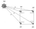
この時、前記受音用マイクモジュールは、前記媒質に複数付着し、複数の受音用マイクモジュールから受音されたノイズ受音信号を用いてノイズに相応する方向が検知され、前記方向に基づいて前記ノイズ除去信号が生成される。 At this time, a plurality of sound receiving microphone modules are attached to the medium, a direction corresponding to the noise is detected using noise sound signals received from the plurality of sound receiving microphone modules, and a direction corresponding to the noise is detected based on the direction. to generate the noise-removed signal.
この時、前記ノイズ受音信号は、前記ノイズに相応する音源の位置を算出するのに用いられ、前記音源の位置に基づいて前記ノイズ除去信号が生成される。 At this time, the noise receiving signal is used to calculate the position of the sound source corresponding to the noise, and the noise removal signal is generated based on the position of the sound source.
この時、前記スピーカドライバは、複数備えられ、複数のスピーカドライバそれぞれと前記音源との間の距離が算出され、前記距離の少なくとも1つに相応するディレイが前記複数のスピーカドライバの少なくとも1つに相応するノイズ除去信号に適用される。 At this time, a plurality of speaker drivers are provided, a distance between each of the plurality of speaker drivers and the sound source is calculated, and a delay corresponding to at least one of the distances is provided to at least one of the plurality of speaker drivers. Applied to the corresponding denoised signal.
この時、前記複数のスピーカドライバの一部は、前記音源に相応するノイズを除去するための前記ノイズ除去信号を生成し、前記複数のスピーカドライバの他の一部は、前記ノイズを除去するための振動を減衰させるための減衰振動を生成することができる。 At this time, some of the plurality of speaker drivers generate the noise removal signal for removing noise corresponding to the sound source, and some of the plurality of speaker drivers are used to remove the noise. can generate a damped oscillation to dampen the oscillation of
この時、前記複数の受音用マイクモジュールおよび前記複数のスピーカドライバは、前記媒質に付着する1つの構造に設けられる。 At this time, the plurality of sound receiving microphone modules and the plurality of speaker drivers are provided in one structure attached to the medium.
この時、前記1つ以上の受音用マイクモジュールおよび前記1つ以上のスピーカドライバを収容し、前記スピーカドライバの後面で発生する漏音(Sound leakage)および前記媒質から伝達される低レベルの騒音を除去するハニカムレゾネータをさらに含むことができる。 At this time, the one or more sound receiving microphone modules and the one or more speaker drivers are accommodated, and sound leakage generated behind the speaker drivers and low-level noise transmitted from the medium can further include a honeycomb resonator that removes the
この時、前記ハニカムレゾネータは、内部がハニカム構造に区分されかつ、1つ以上のハニカム構造を1つの空間に区分する隔壁が形成される。 At this time, the honeycomb resonator is divided into honeycomb structures inside, and partition walls are formed to divide one or more honeycomb structures into one space.
この時、前記ハニカムレゾネータは、内部に吸収された前記漏音および前記騒音の乱反射を増加させるために、内部に形成された各ハニカム構造の底面の高さが異なって形成される。 At this time, the honeycomb resonator is formed so that the height of the bottom surface of each honeycomb structure formed inside is different in order to increase the diffused reflection of the leaked sound and the noise absorbed inside.
この時、前記隔壁は、前記隔壁で形成された空間で除去しようとする周波数に対応する大きさの貫通口が形成される。 At this time, the partition is formed with a through hole having a size corresponding to a frequency to be removed in the space formed by the partition.
この時、前記スピーカドライバは、前記スピーカドライバの後面で発生する漏音を相殺するために、前記スピーカドライバの後面に結合され、多重チャンバ方式で形成される共鳴部をさらに含むことができる。 At this time, the speaker driver may further include a resonator formed in a multi-chamber manner coupled to the rear surface of the speaker driver in order to cancel sound leakage generated at the rear surface of the speaker driver.
この時、前記コントローラは、前記音源の位置および前記ノイズ受音信号に基づいて、第1ファンダメンタル(Fundamental)周波数値を算出し、前記第1ファンダメンタル周波数値に対応する第1ノイズ除去信号を生成して、前記スピーカドライバに伝達し、前記第1ファンダメンタル周波数値に相応する波長が除去されたノイズ受音信号に基づいて、第2ファンダメンタル周波数値を算出し、前記第2ファンダメンタル周波数値に対応する第2ノイズ除去信号を生成して、前記スピーカドライバに伝達し、前記スピーカドライバは、前記コントローラによって伝達された第1ノイズ除去信号および第2ノイズ除去信号に相応する振動を前記媒質に時系列順に伝達することができる。 At this time, the controller calculates a first fundamental frequency value based on the position of the sound source and the noise received signal, and generates a first noise removal signal corresponding to the first fundamental frequency value. a second fundamental frequency value is calculated based on the received noise signal from which the wavelength corresponding to the first fundamental frequency value has been removed, and a second fundamental frequency value corresponding to the second fundamental frequency value is transmitted to the speaker driver; 2 noise elimination signals are generated and transmitted to the speaker driver, and the speaker driver transmits vibrations corresponding to the first noise elimination signal and the second noise elimination signal transmitted by the controller to the medium in chronological order. can do.
この時、前記コントローラは、ユーザによって入力された前記媒質の構造情報に応じて、クラドニパターン(Chladni Pattern)を予測し、前記パターンおよび前記ノイズ受音信号に基づいて前記ノイズ除去信号を生成することができる。 At this time, the controller predicts a Chladni pattern according to the structural information of the medium input by the user, and generates the noise removal signal based on the pattern and the noise pickup signal. be able to.
この時、前記コントローラは、前記音源の位置および前記ノイズ受音信号に基づいて、ファンダメンタル(Fundamental)周波数値およびハーモニクス(Harmonics)周波数値を算出し、前記ファンダメンタル周波数値および前記ハーモニクス周波数値に相応する波形を同時に生成し、同時に生成された前記波形に基づいて前記ノイズ除去信号を生成することができる。 At this time, the controller calculates a fundamental frequency value and a harmonics frequency value based on the position of the sound source and the noise received signal, corresponding to the fundamental frequency value and the harmonics frequency value. Waveforms may be generated simultaneously and the denoised signal may be generated based on the waveforms generated simultaneously.
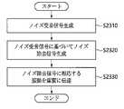
また、上記の目的を達成するために、本発明の一実施例による騒音除去方法は、騒音除去装置により騒音を除去する方法において、受音用マイクモジュールにより媒質から音を受音してノイズ受音信号を生成するステップと、前記ノイズ受音信号に基づいてノイズ除去信号を生成するステップと、スピーカドライバを介して前記ノイズ除去信号に相応する振動を前記媒質に伝達するステップとを含む。 In order to achieve the above object, a noise elimination method according to an embodiment of the present invention is a method for eliminating noise by means of a noise elimination device, wherein a microphone module for sound reception receives sound from a medium to receive noise. generating a sound signal; generating a noise-removed signal based on the noise-receiving signal; and transmitting vibration corresponding to the noise-removed signal to the medium through a speaker driver.
この時、前記受音用マイクモジュールは、前記媒質に複数付着し、前記ノイズ除去信号を生成するステップは、複数の受音用マイクモジュールから受音されたノイズ受音信号を用いてノイズに相応する方向を検知し、前記方向に基づいて前記ノイズ除去信号を生成することができる。 At this time, a plurality of the sound receiving microphone modules are attached to the medium, and the step of generating the noise elimination signal corresponds to the noise using the noise sound signals received from the plurality of sound receiving microphone modules. A direction of movement may be detected and the noise reduction signal may be generated based on the direction.
この時、前記ノイズ除去信号を生成するステップは、前記ノイズ受音信号に基づいて前記ノイズに相応する音源の位置を算出するステップと、前記音源の位置に基づいて前記ノイズ除去信号を生成するステップとを含むことができる。 At this time, the step of generating the noise-removed signal comprises: calculating the position of a sound source corresponding to the noise based on the received noise signal; and generating the noise-removed signal based on the position of the sound source. and
この時、前記スピーカドライバは、複数備えられ、前記複数のスピーカドライバそれぞれと前記音源との間の距離を算出するステップと、前記距離の少なくとも1つに相応するディレイを前記複数のスピーカドライバの少なくとも1つに相応するノイズ除去信号に適用するステップとをさらに含むことができる。 At this time, a step of calculating a distance between each of the plurality of speaker drivers and the sound source and setting a delay corresponding to at least one of the distances to at least one of the plurality of speaker drivers. and applying one corresponding denoised signal.
この時、前記振動を前記媒質に伝達するステップは、前記複数のスピーカドライバの一部を介して前記音源に相応するノイズを除去するための前記ノイズ除去信号に相応する振動を前記媒質に伝達するステップと、前記複数のスピーカドライバの他の一部は前記振動を減衰させるための減衰振動を前記媒質に伝達するステップとを含むことができる。 At this time, the step of transmitting the vibration to the medium includes transmitting the vibration corresponding to the noise elimination signal for eliminating noise corresponding to the sound source to the medium through a portion of the plurality of speaker drivers. and another portion of the plurality of speaker drivers transmitting damping vibrations to the medium for damping the vibrations.
この時、前記受音用マイクモジュールおよび前記スピーカドライバを収容するハニカムレゾネータを介して、前記スピーカドライバの後面で発生する漏音(Sound leakage)および騒音を除去するステップをさらに含むことができる。 At this time, the method may further include removing sound leakage and noise generated behind the speaker driver through a honeycomb resonator accommodating the sound receiving microphone module and the speaker driver.
この時、前記ハニカムレゾネータは、内部がハニカム構造に区分されかつ、1つ以上のハニカム構造を1つの空間に区分する隔壁が形成される。 At this time, the honeycomb resonator is divided into honeycomb structures inside, and partition walls are formed to divide one or more honeycomb structures into one space.
この時、前記ハニカムレゾネータは、内部に吸収された騒音の乱反射を増加させるために、内部に形成された各ハニカム構造の底面の高さが異なって形成される。 At this time, the honeycomb resonator is formed such that the height of the bottom surface of each honeycomb structure formed therein is different in order to increase diffuse reflection of noise absorbed inside.
この時、前記隔壁は、前記隔壁で形成された空間で除去しようとする周波数に対応する大きさの貫通口が形成される。 At this time, the partition is formed with a through hole having a size corresponding to a frequency to be removed in the space formed by the partition.
この時、前記ノイズ除去信号を生成するステップは、前記ノイズ受音信号に基づいて第1ファンダメンタル(Fundamental)周波数値を算出するステップと、前記第1ファンダメンタル周波数値に対応する第1ノイズ除去信号を生成するステップと、前記第1ファンダメンタル周波数値に相応する波長が除去されたノイズ受音信号に基づいて第2ファンダメンタル周波数値を算出するステップと、前記第2ファンダメンタル周波数値に対応する第2ノイズ除去信号を生成するステップとを含み、前記振動を前記媒質に伝達するステップは、前記スピーカドライバを介して前記第1ノイズ除去信号および前記第2ノイズ除去信号に相応する振動を順次に前記媒質に伝達することができる。 At this time, the step of generating the noise-removed signal includes: calculating a first fundamental frequency value based on the noise-receiving signal; and generating a first noise-removed signal corresponding to the first fundamental frequency value. calculating a second fundamental frequency value based on the received noise signal from which the wavelength corresponding to the first fundamental frequency value has been removed; and removing a second noise corresponding to the second fundamental frequency value and the step of transmitting the vibrations to the medium sequentially transmits vibrations corresponding to the first noise reduction signal and the second noise reduction signal to the medium through the speaker driver. can do.
この時、前記ノイズ除去信号を生成するステップは、ユーザによって入力された前記媒質の構造情報に応じて、クラドニパターン(Chladni pattern)を予測するステップと、前記パターンおよび前記ノイズ受音信号に基づいて前記ノイズ除去信号を生成するステップとを含むことができる。 At this time, the step of generating the noise-removed signal includes predicting a Chladni pattern according to structural information of the medium input by a user; and generating the noise-reduced signal.
この時、前記ノイズ除去信号を生成するステップは、前記ノイズ受音信号に基づいてファンダメンタル(Fundamental)周波数値およびハーモニクス(Harmonics)周波数値を算出するステップと、前記ファンダメンタル周波数値および前記ハーモニクス周波数値に相応する波形を同時に生成するステップと、前記波形に基づいて前記ノイズ除去信号を生成するステップとを含むことができる。 At this time, the step of generating the noise-removed signal includes: calculating a fundamental frequency value and a harmonics frequency value based on the noise-receiving signal; simultaneously generating a corresponding waveform; and generating the noise reduction signal based on the waveform.
本発明によれば、媒質を通して伝達される騒音を除去することができる。
また、本発明によれば、騒音源の位置を分析して正確に騒音を除去することができる。According to the invention, noise transmitted through the medium can be eliminated.
Also, according to the present invention, noise can be removed accurately by analyzing the position of the noise source.
さらに、本発明によれば、同一の地点に設けられたスピーカドライバの振動をマイクモジュールに伝達されないようにすることができる。 Furthermore, according to the present invention, it is possible to prevent the vibration of the speaker driver provided at the same point from being transmitted to the microphone module.
また、本発明によれば、騒音を除去するスピーカドライバの漏音を遮断することができる。 Further, according to the present invention, it is possible to block sound leakage from a speaker driver that removes noise.
なお、本発明によれば、電灯、エアコンのような一般器具と融合可能な騒音除去装置を提供することができる。 In addition, according to the present invention, it is possible to provide a noise elimination device that can be combined with general appliances such as electric lights and air conditioners.
本実施例の効果は上記の効果に制限されず、言及されていないさらに他の効果は特許請求の範囲の記載から通常の技術者に明確に理解されるであろう。 The effects of this embodiment are not limited to the effects described above, and other effects not mentioned will be clearly understood by those of ordinary skill in the art from the description of the claims.
以下、本発明を添付した図面を参照して詳細に説明する。ここで、繰り返しの説明、本発明の要旨を不必要にあいまいにしうる公知の機能、および構成に関する詳細な説明は省略する。本発明の実施形態は当業界における平均的な知識を有する者に本発明をより完全に説明するために提供されるものである。したがって、図面における要素の形状および大きさなどはより明確な説明のために誇張されることがある。 Hereinafter, the present invention will be described in detail with reference to the accompanying drawings. Here, repetitive descriptions and detailed descriptions of well-known functions and configurations that may unnecessarily obscure the subject matter of the present invention are omitted. Rather, the embodiments of the present invention are provided so that the present invention may be fully understood by those of ordinary skill in the art. Therefore, the shapes, sizes, etc. of elements in the drawings may be exaggerated for clearer explanation.
騒音について説明すれば、等ラウドネス曲線により、低音は相対的に人の耳によく聞こえないが、大きいエネルギーを含んでいて、長期間露出時に不快感を生じることがある。 In terms of noise, due to the equal loudness curve, bass sounds are relatively inaudible to the human ear, but they contain a lot of energy and can cause discomfort during long-term exposure.
低音は相対的に大きい波長を有していて壁または構造物を容易に透過可能で伝達力が強く、密度が異なる部分(例えば、壁の角、出入扉、窓など)で回折と干渉が起こりやすいという特徴がある。 Low-frequency waves have relatively large wavelengths and can easily pass through walls or structures with strong transmission power. Diffraction and interference occur in areas with different densities (e.g., corners of walls, doors, windows, etc.). It has the advantage of being easy.
したがって、低音除去は、騒音流入防止のための重要な部分である。
高音は相対的に小さい波長を有していて壁を透過しにくく、吸音、遮壁などの処理で伝播を防止することができる。Therefore, bass cancellation is an important part of noise intrusion prevention.
High-pitched sounds have relatively small wavelengths and are difficult to pass through walls, and can be prevented from propagating by treatment such as sound absorption and shielding walls.
高音は低音に対する倍音成分を多数含んでおり、可聴周波数帯域を超える高い周波数は人が直接聞くことはできなくても不快感を生じることがある。 High-pitched sounds contain many overtone components with respect to low-pitched sounds, and high frequencies exceeding the audible frequency band may cause discomfort even if people cannot hear them directly.
層間騒音を直接的に発生させる衝撃音は、トランシエント(Transient)特性を有し、周波数の全帯域にわたってその成分が存在する。 Impulsive sound that directly generates inter-story noise has transient characteristics and its components exist over the entire frequency band.
また、前記衝撃音は一般的な倍音構造を有しないが、低域帯に高いエネルギーが含まれている。 Also, the impulsive sound does not have a general harmonic structure, but contains high energy in the low frequency band.
さらに、前記衝撃音は、実際に聴取するものより高い音圧を有しているが、等ラウドネス曲線(Equal loudness Curve-Fletcher&Munson)の特性により、低音は実際より小さく聞こえるようになる。 Furthermore, the impact sound has a higher sound pressure than what is actually heard, but due to the characteristics of the equal loudness curve (Fletcher & Munson), the bass sounds lower than they actually are.
また、前記衝撃音は、媒質に沿って伝播する過程で増幅可能であり、特に媒質が変化する地点で発振を起こして層間騒音をより大きく誘発することもある。 In addition, the impact sound can be amplified while propagating along the medium, and in particular, it may oscillate at a point where the medium changes, thereby causing greater interlayer noise.
以下、本発明による好ましい実施例を添付した図面を参照して詳しく説明する。
図1は、本発明の一実施例による騒音除去装置の斜視図である。Hereinafter, preferred embodiments of the present invention will be described in detail with reference to the accompanying drawings.
FIG. 1 is a perspective view of a noise eliminator according to one embodiment of the present invention.
図1を参照すれば、本発明の一実施例による騒音除去装置は、1つ以上の受音用マイクモジュールおよび1つ以上のスピーカドライバを媒質に付着する1つの構造に形成される。 Referring to FIG. 1, a noise eliminator according to an embodiment of the present invention is formed in one structure by attaching one or more sound receiving microphone modules and one or more speaker drivers to a medium.
一実施例としては、天井や、壁、床に付着可能であり、灯器具、エアコン、空気清浄機などの電気および電子製品に内蔵されてもよい。 As an example, it can be attached to ceilings, walls, and floors, and can be built into electrical and electronic products such as lighting fixtures, air conditioners, and air cleaners.
また、一実施例は、机、ベッドなどのような家具に内蔵されてもよいし、車両などのように振動が発生するいかなる所にも設置可能である。 Also, one embodiment can be installed in furniture such as a desk, bed, etc., or can be installed in any place where vibration occurs, such as a vehicle.
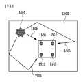
図2は、本発明の一実施例による騒音除去装置の分解図である。
図2を参照すれば、本発明の一実施例による騒音除去装置は、上端カバー201と、マイク内蔵型スピーカ装置203(またはマイクモジュールとスピーカドライバが区分されて含まれていてもよい)と、リファレンスマイクモジュール205と、ハニカムレゾネータ207と、イマーシブ再生用スピーカドライバ209と、側面カバー211と、LEDパネル213と、支持用フレーム215と、ディスプレイおよびセンサ219と、DSP(Digital Signal Processor)217とを含むことができる。FIG. 2 is an exploded view of a noise eliminator according to one embodiment of the present invention.
Referring to FIG. 2, the noise canceling apparatus according to an embodiment of the present invention includes an
この時、上端カバー201、側面カバー211は、内部構成要素を収容できるように形成される。 At this time, the
この時、マイク内蔵型スピーカ装置203は、受音と再生を1つのポイントに縮小させてレイテンシー(Latency、遅延時間)を無くし、プロセッシングパワーを低減することができる。 At this time, the microphone built-in
また、マイク内蔵型スピーカ装置203は、マイクモジュールとスピーカドライバとを含み、同一のポイントを指向できるように配置される。 Also, the microphone built-in
さらに、マイク内蔵型スピーカ装置203は、マイクモジュールとスピーカドライバとを含み、再生方向が異なるイマーシブスピーカ209を含ませることができる。 Further, the microphone built-in
この時、リファレンスマイクモジュール205は、騒音の流入方向を探知するための基準となり得る。 At this time, the
この時、リファレンスマイクモジュール205は、騒音除去駆動をプロセッシングするための基準信号として使用できる。 At this time, the
この時、ハニカムレゾネータ207は、マイク内蔵型スピーカ装置203またはスピーカドライバの後面部で生成される音および天井を通して流入する騒音を共鳴の原理で相殺させる役割を果たすことができる。これに関しては、図3を参照して後述する。 At this time, the
この時、イマーシブ(Immersive)再生用スピーカドライバ209は、間接音に対する騒音を除去することができる。間接音については後述する。 At this time, the immersive
図3は、本発明の一実施例によるハニカムレゾネータの斜視図である。
図3を参照すれば、本発明の一実施例によるハニカムレゾネータ207は、1つ以上の受音用マイクモジュールおよび1つ以上のスピーカドライバを収容し、スピーカドライバの後面で発生する漏音(Sound leakage)および前記媒質から伝達される低レベルの騒音を除去することができる。FIG. 3 is a perspective view of a honeycomb resonator according to one embodiment of the present invention.
Referring to FIG. 3, a
複数のスピーカドライバを用いる騒音除去装置は、スピーカドライバを介して媒質に振動を伝達するが、前記スピーカドライバの後面で再生される騒音は内部空間に流入し、騒音除去に関係なくさらに他の騒音を誘発することがある。 A noise elimination device using a plurality of speaker drivers transmits vibrations to a medium through the speaker drivers, but the noise reproduced behind the speaker drivers flows into the internal space, and other noises are generated regardless of the noise elimination. may induce
この時、ハニカムレゾネータ207は、内部がハニカム構造に区分されかつ、1つ以上のハニカム構造を1つの空間に区分する隔壁301が形成される。 At this time, the
より詳しくは、ハニカムレゾネータ207は、内部をハニカム構造化し、互いに異なる面積をもたせて、ヘルムホルツ共鳴器の原理によりスピーカドライバから発生する騒音を除去することができる。 More specifically, the
この時、隔壁は、共鳴器の体積を作るための用途として面積を分割することができる。例えば、低音を除去できるように8個のハニカムを1個の隔壁301にし、中音を除去するために4個のハニカムを1個の隔壁301にし、高音を除去するために1個の隔壁301にすることができる。 The diaphragm can then divide the area as a use to create the volume of the resonator. For example, 8 honeycombs are combined into one
ヘルムホルツ理論によれば、面積が広い空間は低音を除去し、面積が小さい空間は高音を除去することができるからである。 This is because, according to the Helmholtz theory, a space with a large area can eliminate low frequencies, and a space with a small area can eliminate high frequencies.
この時、隔壁301は、目的とする周波数を最適化するために、目的とする周波数に相応する互いに異なる大きさの穴305を形成することができる。 At this time, in order to optimize a target frequency, the
また、ハニカムレゾネータ207は、騒音を効率的に吸音するために、内部に吸音材を用いることができる。 In addition, the
さらに、ハニカムレゾネータ207は、内部に吸収された前記漏音および前記騒音の乱反射を増加させるために、内部に形成された各ハニカム構造の底面303の高さが異なって形成される。 In addition, the
図4は、本発明の一実施例により騒音を除去するフローチャートである。
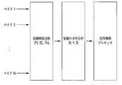
図4を参照すれば、本発明の一実施例は、複数のマイクおよびプリアンプを含むコンタクトマイクにより騒音信号を受音することができる。FIG. 4 is a flow chart of removing noise according to one embodiment of the present invention.
Referring to FIG. 4, one embodiment of the present invention can receive noise signals with a contact microphone that includes multiple microphones and preamplifiers.
この時、受音された騒音信号は、入力プロセッサによってGATEで特定のレベルで動作するようにレベルを測定し、FILTERを介して不要周波数を削除することができ、AGC(Auto Gain Cotroller)を介して出力レベルに応じた自動ゲインをコントロールすることができる。 At this time, the level of the received noise signal is measured by the input processor so that the GATE operates at a specific level. can control the automatic gain according to the output level.
この時、多チャネルスペクトルアナライザは、前記騒音信号をチャネル毎にスペクトル分析を行うことができ、トランシエント時間差分析により音源の位置と方向を分析することができ、スペクトル分析により衝撃音が発生した周波数を探知することができる。 At this time, the multi-channel spectrum analyzer can perform spectral analysis on the noise signal for each channel, analyze the position and direction of the sound source by transient time difference analysis, and analyze the frequency of the impact sound by spectral analysis. can be detected.
また、前記多チャネルスペクトルアナライザは、基準レベルを超える周波数と音量を分析し、目標周波数のピーク点を確保することができる。 In addition, the multi-channel spectrum analyzer can analyze frequencies and volumes above a reference level to ensure peak points of target frequencies.
この時、位相比較器は、入力される周波数のスペクトル分析および出力時に多チャネルスピーカを再生した時の変化する波長の形を予め予測することができる。 At this time, the phase comparator can analyze the spectrum of the input frequency and predict in advance the shape of the wavelength that will change when the multi-channel speaker reproduces the output.
この時、学習用プロセッサは、よく発生する騒音に対するADSR(Attack time、Decay time、Sustain level、Release time)を分析することができ、スペクトル分析によりピークの流れが把握されたデータを確保して学習することができる。 At this time, the learning processor can analyze ADSR (Attack time, Decay time, Sustain level, Release time) for frequently occurring noise, and learn by securing data that grasps the peak flow through spectrum analysis. can do.
この時、フェーズプロセッサは、前記騒音信号の正確な逆相信号を作るための演算を行うことができ、基準を超える周波数でのみ逆相が発生するように設定することもできる。また、周波数毎ピークに相当する波長を追跡することもでき、前記学習用プロセッサによって学習されたデータに応じて逆相信号を最適化することもできる。 At this time, the phase processor can perform calculations to create an accurate anti-phase signal of the noise signal, and can be set so that anti-phase occurs only at frequencies exceeding the reference. It is also possible to track the wavelength corresponding to the peak for each frequency and to optimize the anti-phase signal according to the data learned by the learning processor.
この時、スピーカコントローラは、複数のスピーカで最適化された波長をコントロールすることができ、複数の組み合わせによって変更が予想される波長データを抽出することもできる。 At this time, the speaker controller can control the wavelengths optimized by the plurality of speakers, and can also extract wavelength data expected to change due to a plurality of combinations.
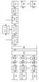
図5は、本発明の一実施例による騒音除去装置のブロック図である。
図5を参照すれば、REF.MIC501は、複数のマイクを用いる時の、基準となるマイクであって、N個に相当するマイクの入力信号を比較する基準となり得る。FIG. 5 is a block diagram of a noise canceller according to one embodiment of the present invention.
Referring to FIG. 5, REF. The
この時、REF.MIC501は、装置の中央に付着して騒音源の方向を認識し、オーディオプロセッシングの基準となる信号をピックアップすることができ、コンタクトマイクまたはピエゾマイクであってもよい。 At this time, REF. The
MIC(N)503は、別のマイクモジュールであるか、マイク内蔵型スピーカ装置に内蔵されたマイクモジュールであってもよいし、コンタクトマイクまたはピエゾマイクであってもよい。 The MIC(N) 503 may be another microphone module, a microphone module built into a speaker device with a built-in microphone, or a contact microphone or piezo microphone.
この時、MIC(N)503は、REF.MIC501とともに、騒音源の方向および距離を探知し、オーディオプロセッシングの基準となる信号をピックアップすることができる。 At this time, MIC(N) 503 is REF. Together with the
SPECTRUM ANALYZER505は、それぞれのマイクにより入力される信号から、ファンダメンタル周波数、ハーモニクス周波数、レベル、ディレイ、ADSR、ノイズフロアなどの基礎オーディオデータを抽出することができる。
PHASE COMPARATOR507は、位相比較器であって、REF.MIC501を基準としてN個のマイクに対する位相を分析し、分析された波形を位置検知プロセッサに伝達することができる。
DELAY COMPARATOR509は、信号遅延比較器であって、REF.MIC501を基準としてN個のマイク入力に対するディレイ値を分析し、分析された値を位置検知プロセッサに伝達することができる。
AMPLITUDE/GATE COMPARATOR511は、増幅ゲート比較器であって、REF.MIC501を基準としてN個のマイク入力に対するオーディオレベル値を位置検知プロセッサに伝達し、すべてのマイクの暗騒音レベルを比較してプロセッシングとバイパスを決定するように比較することができる。 AMPLITUDE/
FUNDAMENTAL/HARMONICS ANALYZER515は、ファンダメンタルおよびハーモニクス分析器であって、スペクトルで分析された周波数成分からファンダメンタル周波数を検知し、当該周波数に対するハーモニクス周波数を分析してフーリエ変換装置に伝達することができる。 The FUNDAMENTAL/
FEEDBACK DETECTOR519は、フィードバック検知器であって、フィードバック信号が検知される場合、検知された周波数をフィードバック除去装置に当該周波数値を伝達することができる。 The FEEDBACK DETECTOR 519 is a feedback detector that, if a feedback signal is detected, can pass the detected frequency value to the feedback cancellation device.
POSITION DETECTOR513は、位置検知器であって、複数のマイクにより分析された位相、ディレイ、レベルを分析して騒音源の位置を分析することができ、分析された方向情報および当該値をDSPに伝達することができる。 The
FOURIER TRANSFORM517は、フーリエ変換器であって、ファンダメンタル周波数を分析し、ハーモニクス周波数を分析して、DSPにより逆相の信号を発進または検証可能なデータとして使用できるようにする。 The
FEEDBACK DESTROYER521は、フィードバック除去器であって、フィードバック検知器によって検知されたフィードバック発生周波数を遮断することができる。 FEEDBACK DESTROYER 521 is a feedback canceller that can cut off the feedback generated frequencies detected by the feedback detector.
COMPARATOR MODULEは、比較器モジュールであって、位相、ディレイ、レベルなどの信号を分析して騒音源の位置を追跡し、オーディオ波形を分析して逆相のオーディオ信号を作ることができる。 The COMPARATOR MODULE is a comparator module that analyzes signals such as phase, delay, and level to track the location of noise sources, and analyzes audio waveforms to create phase-inverted audio signals.
DSP523は、比較器モジュールを介して入力された信号を分析し処理して、複数のスピーカで騒音除去信号を複合演算して出力することができる。 The
この時、DSP523は、無線IOを用いたコントロールおよびディスプレイ機能を含むことができ、学習プロセッサを介した騒音除去機能も学習することができる。 At this time, the
PHASE CONTROLLER525は、位相制御器であって、DSP523を介して出力されるN個の出力信号に対する位相を制御することができる。
AGC527は、自動レベル制御器であって、DSP523を介して出力されるN個の出力に対するゲインを制御することができる。
MATRIX529は、マトリクス制御器であって、位相およびゲイン調整済みのN個の出力信号に対して、スピーカに信号を伝達するためのシグナルマトリクスを制御することができる。
SPEAKER(N)531は、騒音除去用スピーカであって、マトリクス制御器を介して最終出力される信号を用いてダイレクト音に対する騒音を除去することができ、媒質に振動を直接伝達するエキサイタ形式のスピーカであってもよい。 The SPEAKER (N) 531 is an exciter-type speaker that can eliminate the noise of the direct sound using the signal that is finally output through the matrix controller, and that directly transmits vibration to the medium. It may be a speaker.
POSITION DETECTOR533は、位置検知器であって、ユーザが位置した地点を検知してユーザ位置制御器に信号を伝達することができる。 The
USER POSTION COTROLLER535は、ユーザ位置制御器であって、位置検知器を介して自動的に位置を検知したり、ユーザが指定した領域に対してトランスオーラル(Transaural)プロセッサを用いて当該地域にトランスオーラル信号を発生させることができる。 The
TRANSAURAL PROCESSOR537は、トランスオーラルプロセッサであって、ダイレクト音から除去できない高周波をトランスオーラルで除去することができる。この時、マトリクス制御器を介して出力される信号をトランスオーラルに変換してトランスオーラル再生スピーカに伝達することができる。
TRASAURAL SPEAKER539は、トランスオーラル再生スピーカであって、トランスオーラルプロセッサを介して入力された信号を用いてルームノイズを除去することができ、ラウドスピーカ装置であってもよい。 The
LEARNING PROCESSOR541およびMEMORYは、学習用プロセッサおよび記憶装置であって、よく発生する騒音を学習用データとして格納し、格納された内容と同じ騒音が発生した場合、完璧に除去可能な逆相の波形を格納し再生できるようにする。
WIRELESS I/O543は、無線入出力装置であって、リモコンまたはPC、スマートフォンのようなモバイル機器であってもよいし、ユーザのコントロール命令を伝達したり、DSP523および検知装置で検知された情報をユーザに伝達することが可能ないかなる装置が含まれていてもよい。 The WIRELESS I/
USER COTROLLER/MONITOR547は、ユーザコントローラおよびモニタであり、DISPLAY I/O545は、ディスプレイ入出力装置であってもよい。 USER CONTROLLER/
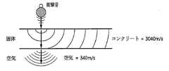
図6は、媒質によって音波の速度を示す概念図である。
一般的に、騒音は媒質に沿って移動し、媒質は空気を振動させて騒音を発生させる。FIG. 6 is a conceptual diagram showing the velocity of sound waves depending on the medium.
In general, noise travels along a medium, which vibrates air to produce noise.
この時、すでに空気中に放射された騒音は、回折、反射、干渉、消滅などによって変形して逆相信号を発生させても除去が困難である。 At this time, the noise already radiated into the air is deformed by diffraction, reflection, interference, annihilation, etc., and is difficult to remove even if a reversed-phase signal is generated.
したがって、媒質によって伝播する騒音は、空気中に放射される前に媒質伝播段階で除去することが好ましく、媒質によって伝播する騒音を受音し、これによる逆相信号を前記媒質に伝達して騒音を除去することができる。 Therefore, the noise propagated by the medium is preferably removed in the medium propagation stage before being radiated into the air. can be removed.
しかし、音速は、空気での伝播速度と特定の媒質での伝播速度とが異なっていて、一般的な音速を基準として逆相信号を生成する場合、正確な騒音除去が行われない。 However, the speed of sound differs between the speed of propagation in air and the speed of propagation in a specific medium, and accurate noise cancellation is not achieved when generating anti-phase signals based on the general speed of sound.
図6を参照すれば、空気中での音速は340m/sであるのに対し、媒質(固体)のうちコンクリートでの音速は3040m/sで速度の差が非常に大きい。 Referring to FIG. 6, the speed of sound in air is 340 m/s, whereas the speed of sound in concrete among mediums (solids) is 3040 m/s, showing a large speed difference.
また、媒質に伝播する周波数は変更されず、伝達される音速のみ異なるため、結果的に波長の長さが異なる。 Moreover, since the frequency propagating in the medium is not changed and only the speed of sound transmitted is different, the length of the wavelength is different as a result.
騒音除去は、音波に相当する逆波長を再生して騒音を相殺させなければならないので、スピーカで再生される音は、空気中ではない媒質に振動板が接触して媒質に音波が伝達できるようにしなければならず、媒質に振動を発生させることが可能なエキサイタスピーカを用いることができる。 In order to eliminate noise, it is necessary to cancel the noise by reproducing the reverse wavelength corresponding to the sound wave. and an exciter speaker capable of generating vibrations in the medium can be used.
目標とする媒質に相当する音波の速度は、下記数式1のように定義することができる。 The velocity of the sound wave corresponding to the target medium can be defined as

この時、pは媒質の密度(kg/m^3)であり、Bはバルクモジュールの弾性係数(N/m^2)であり、PはPressure、VはVelocityである。 At this time, p is the density of the medium (kg/m̂3), B is the elastic modulus of the bulk module (N/m̂2), P is Pressure, and V is Velocity.
前記数式1により、媒質での音波の速度を知ることができ、周波数に対する波長値は、下記数式2により求められる。 The velocity of the sound wave in the medium can be obtained from

この時、媒質における音の速度を知り、周波数を知ることができるため、正確な波長の長さを抽出することができ、波長に対する逆相を適用して位相を反転させることができる。 Then, knowing the speed of sound in the medium and knowing the frequency, the exact wavelength length can be extracted, and the phase inverse can be applied to the wavelength to reverse the phase.
上述した方式により、騒音源として流入する音は、コンタクトマイクにより受音し、エキサイタスピーカを介して逆相の振動を媒質に伝達して騒音を相殺することができる。 According to the method described above, the sound coming in as the noise source is received by the contact microphone, and the vibration of the opposite phase is transmitted to the medium through the exciter speaker to cancel the noise.
図7は、本発明の一実施例によるスピーカドライバの分解図である。
密度の高い媒質に振動を伝達するためには、十分な振動エネルギーを有するスピーカ装置が要求される。FIG. 7 is an exploded view of a speaker driver according to one embodiment of the invention.
A speaker device with sufficient vibrational energy is required to transmit vibrations to a medium with high density.
図7を参照すれば、本発明の一実施例によるスピーカドライバは、直接媒質に付着して振動を伝達できるように形成される。 Referring to FIG. 7, a speaker driver according to an embodiment of the present invention is formed to be directly attached to a medium and transmit vibration.
この時、振動を発進するスピーカドライバの振動部は、媒質と同じ密度を有する素子を用いかつ、低い出力でも振動を作り出すことが可能な素子を用いて振動を増幅することもできる。 At this time, the vibrating portion of the speaker driver that initiates the vibration can amplify the vibration by using an element that has the same density as the medium and that can generate vibration even with a low output.
この時、スピーカドライバ(ダイヤフラム)の再生特性は、高音成分が再生(1kHz以上の周波数)されないように調整可能であり、前記再生特性を維持するために、信号の増幅部は、LPF(Low Pass Filter)が含まれてもよい。 At this time, the reproduction characteristics of the speaker driver (diaphragm) can be adjusted so that high-pitched sound components are not reproduced (frequency of 1 kHz or higher). Filter) may be included.
図7を参照してより詳しく説明すれば、本発明の一実施例によるスピーカドライバは、振動部と、磁石と、ボイスコイルと、ボイスコイル固定部と、固定ブラケットとを含み、媒質に付着して振動を発生させる。 7, a speaker driver according to an embodiment of the present invention includes a vibrating part, a magnet, a voice coil, a voice coil fixing part, and a fixing bracket, and adheres to a medium. to generate vibration.
この時、ボイスコイルは、前記マイクモジュールにより印加される逆相信号によって磁場を発生させる。 At this time, the voice coil generates a magnetic field according to the antiphase signal applied by the microphone module.
この時、前記信号は、スピーカドライバに出力したサウンド信号であってもよいし、前記磁場によって磁石を動かすことができる。 At this time, the signal may be a sound signal output to the speaker driver, or the magnetic field may move the magnet.
この時、ボイスコイル固定部は、前記各構成要素を収容しかつ、ボイスコイルの外側でボイスコイルの位置を固定することができる。 At this time, the voice coil fixing part can accommodate the components and fix the position of the voice coil outside the voice coil.
この時、ボイスコイルは、ボイスコイル固定部によって媒質に対する相対的な位置が可変するのを防止することができる。 At this time, the voice coil can be prevented from changing its position relative to the medium by the voice coil fixing portion.
この時、ボイスコイルは、ボイスコイル固定部の内部に位置しかつ、磁石に対する相対位置が可変できる。 At this time, the voice coil is positioned inside the voice coil fixing portion, and its relative position to the magnet can be varied.
前記相対位置を可変する理由は、磁石に対するボイスコイルの位置に応じて音特性が異なることを利用するためである。 The reason for varying the relative position is to utilize the fact that sound characteristics differ according to the position of the voice coil with respect to the magnet.
一般的に、ボイスコイルと磁石は、ボイスコイルを中心として1/2の水準にて互いに位置していなければならず、ボイスコイルと磁石とが遠くなる場合には、出力低下、低音低下現象が発生して、結局、高音しか聞こえなくなり、ボイスコイルと磁石とが隣接するほど、出力は上昇し、低音は増加する。 In general, the voice coil and the magnet should be positioned at 1/2 level with respect to the voice coil. As a result, only high-pitched sounds can be heard, and the closer the voice coil and the magnet are, the higher the output and the more low-pitched sounds.
したがって、本発明の一実施例によるスピーカドライバは、磁石またはボイスコイルの位置を外部から細部的に動くことができるようにして、効率および音質をユーザが望む通りに調整することができる。 Therefore, the speaker driver according to one embodiment of the present invention allows the position of the magnet or voice coil to be finely moved from the outside so that the efficiency and sound quality can be adjusted as desired by the user.
この時、本発明の一実施例によるスピーカドライバは、ボイスコイル固定部の内部に位置しかつ、内周面に前記ボイスコイルを固定する固定溝と、外周面に第1ねじ山が形成されるボイスコイル支持部をさらに含み、前記ボイスコイルは、前記固定溝に固定され、ボイスコイル固定部の内周面に前記第1ねじ山に対応する第2ねじ山が形成されて、ボイスコイル固定部の回転によってボイスコイル支持部の位置が可変するように構成される。 At this time, the speaker driver according to one embodiment of the present invention is positioned inside the voice coil fixing part and has a fixing groove for fixing the voice coil on the inner peripheral surface and a first screw thread on the outer peripheral surface. A voice coil supporter is further included, wherein the voice coil is fixed in the fixing groove, and a second screw thread corresponding to the first screw thread is formed on an inner peripheral surface of the voice coil fixing member to form a voice coil fixing member. is configured to change the position of the voice coil support portion by the rotation of the .
この時、磁石は、前記ボイスコイルの内側に位置しかつ、前記磁場によって動くことができる。 A magnet is then located inside the voice coil and can be moved by the magnetic field.
この時、前記動きは、上下方向の振動であってもよいし、磁石の振動は振動部に伝達される。 At this time, the movement may be vertical vibration, and the vibration of the magnet is transmitted to the vibrating portion.
この時、振動部は、一面が前記媒質に接触して伝達された振動を前記媒質に伝達することができる。 At this time, one surface of the vibrating part may contact the medium and transmit the transmitted vibration to the medium.
この時、振動部は、パラボラ形状に形成されて、前記媒質に接触する一側面に内部に陥没したマイク収容部を含むことができ、前記マイクモジュールは、前記マイク収容部に前記振動部と離隔して位置することができる。 At this time, the vibrating part may include a microphone accommodating part that is formed in a parabolic shape and is recessed in one side contacting the medium, and the microphone module is separated from the vibrating part in the microphone accommodating part. can be located as
この時、振動部は、真ん中に貫通口が形成され、前記マイクモジュール支持用ポールが前記貫通口を通過して位置しかつゴムリングによって固定され、前記マイクモジュール支持用ポールの一端が前記マイクモジュールまたは前記マイクモジュールのフィードバック遮断ハウジングと固定結合される。 At this time, the vibrating part is formed with a through hole in the middle, the microphone module supporting pole is positioned through the through hole and fixed by a rubber ring, and one end of the microphone module supporting pole is connected to the microphone module. Or fixedly coupled with the feedback block housing of the microphone module.
この時、サスペンションリングは、振動部と磁石との間に振動が五感により衝撃量が累積して破損するのを防止するために含まれてもよいし、軟質の素材で形成される。 At this time, the suspension ring may be included between the vibrating part and the magnet in order to prevent damage due to accumulation of impact due to vibration, and is made of a soft material.
この時、磁石が振動後元の位置に復帰できるように、磁石の一面に位置する支持スプリングをさらに含むことができる。 At this time, a support spring positioned on one side of the magnet may be further included so that the magnet can return to its original position after being vibrated.
この時、支持スプリングは、マルチレイヤを有するウェーブスプリング(Wave spring)であってもよい。 At this time, the support spring may be a wave spring having multiple layers.
この時、支持スプリングは、複数のレイヤを有するウェーブスプリングの厚さを互いに異ならせることで、低出力で反応速度を高め、高出力でもディストーションが発生する問題点を改善することができる。 At this time, the support spring can improve the reaction speed at low power and improve the problem of distortion even at high power by varying the thickness of the wave spring having a plurality of layers.
例えば、本発明の一実施例によるウェーブスプリングは、レイヤa、レイヤbおよびレイヤcを含むマルチレイヤ構造を有することができ、各レイヤの厚さは、a<b<cをなすように構成される。 For example, a wavespring according to one embodiment of the present invention may have a multi-layer structure including layer a, layer b and layer c, where the thickness of each layer is configured such that a<b<c. be.
この時、ウェーブスプリングは、低出力の小さい音の再生ではレイヤaのみ動き、高出力の大きい音の再生ではレイヤa、bおよびcがともに動くことができる。 At this time, the wavespring can move only layer a when playing a low-power, small sound, and move all layers a, b, and c when playing a high-power, loud sound.
したがって、本発明の一実施例によるウェーブスプリングは、出力に応じて異なるスプリング復元力を有することにより、トランシエント特性が非常に強い音が瞬間的に入力されてもディストーションが発生せず速やかな復元力を有することができ、ダンピングファクターを最大化することができる。 Therefore, the wave spring according to an embodiment of the present invention has different spring restoring force according to the output, so that even if a sound with a very strong transient characteristic is instantaneously input, distortion does not occur and the wave spring quickly restores. force and maximize the damping factor.
また、ウェーブスプリングは、既存のスプリングに比べて最小1/2以上厚さを低減できて製品の大きさを増加させず、復元力が非常に強くて長期間の使用にも変形が発生しない。 In addition, the wave spring can be reduced in thickness by at least 1/2 compared to the existing spring, does not increase the size of the product, and has a very strong restoring force, so that it does not deform even after long-term use.
さらに、スピーカドライバは、各構成要素を収容するために、上端カバー、下端カバーをさらに含むことができ、ボイスコイル固定部を側面カバーとして用いることもできる。 In addition, the speaker driver may further include a top cover and a bottom cover to accommodate each component, and the voice coil fixing part may be used as a side cover.
この時、スピーカドライバの性能を向上させるために、ボイスコイルの内側面にアルミニウム箔をさらに含んでもよい。 At this time, an aluminum foil may be further included on the inner surface of the voice coil in order to improve the performance of the speaker driver.
この時、固定ブラケットは、前記媒質に対するボイスコイルの位置が可変するのを防止するために、一端はボイスコイル固定部に固定され、他端は前記媒質に固定される。 At this time, the fixing bracket has one end fixed to the voice coil fixing part and the other end fixed to the medium in order to prevent the position of the voice coil from changing with respect to the medium.
また、固定ブラケットは、一端が上端カバーと結合して媒質に固定されてもよい。
この時、固定ブラケットの一端の内周面にはねじ山が形成され、ボイスコイル固定部または上端カバーの外周面には前記ねじ山に対応するねじ山が形成されて、相互ねじ結合によって結合されてもよい。Also, one end of the fixing bracket may be coupled with the upper end cover and fixed to the medium.
At this time, a thread is formed on the inner peripheral surface of one end of the fixing bracket, and a thread corresponding to the thread is formed on the outer peripheral surface of the voice coil fixing part or the upper end cover, and they are connected by mutual screw connection. may
さらに、固定ブラケットは、円筒状に形成されかつ、媒質と接触する一端の外周縁には外へ拡張する接触部をさらに含むことができ、前記接触部には前記媒質と結合できるように1つ以上の貫通口を含むことができる。 Further, the fixing bracket may be formed in a cylindrical shape and further include a contact portion extending outward from an outer peripheral edge of one end in contact with the medium, and the contact portion may have one contact portion so as to be coupled with the medium. The above through holes can be included.
図8は、本発明の一実施例によるスピーカドライバおよび共鳴部の断面図である。
図8を参照すれば、本発明の一実施例による騒音除去装置は、スピーカドライバ801の一面に発散する周波数を効果的に吸収除去するために、共鳴部803をさらに含むことができる。FIG. 8 is a cross-sectional view of a speaker driver and resonator according to one embodiment of the present invention.
Referring to FIG. 8, the noise eliminator according to an embodiment of the present invention may further include a
この時、共鳴部803は、スピーカドライバ801のハウジングとして使用可能であり、多様な周波数を同時に除去できるように複数の穴が形成され、前記穴に対する体積も互いに異なって形成される。 At this time, the

この時、fは相殺しようとする周波数であり、cは音の速度であり、Sは穴の面積であり、Lは穴から共振部までの距離であり、Vは共振部の体積である。 At this time, f is the frequency to be canceled, c is the speed of sound, S is the area of the hole, L is the distance from the hole to the resonator, and V is the volume of the resonator.
この時、共鳴部803は、多重チャンバ方式で形成される。
図9は、本発明の一実施例によるマイクモジュールの分解図である。At this time, the
FIG. 9 is an exploded view of a microphone module according to one embodiment of the invention.
図9を参照すれば、本発明の一実施例によるマイクモジュールは、密度の高い媒質の振動信号を受音するために、一般的なマイクよりは振動のみを受音可能なコンタクトマイクを用いることができる。 Referring to FIG. 9, a microphone module according to an embodiment of the present invention uses a contact microphone capable of receiving only vibration rather than a general microphone in order to receive vibration signals of a medium with high density. can be done.
この時、コンタクトマイクは、空気中の音は受音せず、媒質によって振動する周波数のみを受音することができる。 At this time, the contact microphone does not pick up the sound in the air, but can pick up only the frequency vibrating with the medium.
この時、マイクモジュールは、第1帯域を目標帯域として媒質から音を受音し、第1受音信号を生成する高音用コンタクトマイクと、前記第1帯域より低い周波数帯域である第2帯域を目標帯域として前記媒質から音を受音し、第2受音信号を生成する低音用コンタクトマイクと、前記第1受音信号および前記第2受音信号を合算して前記受音信号を生成するマイクコントローラとを含むことができる。 At this time, the microphone module receives sound from a medium with a first band as a target band and generates a first received sound signal, and a contact microphone for high-pitched sounds, and a second band, which is a lower frequency band than the first band. A bass contact microphone that receives sound from the medium as a target band and generates a second received sound signal, and a sum of the first received sound signal and the second received sound signal to generate the received sound signal. and a microphone controller.
この時、前記第1帯域および前記第2帯域は、クロスオーバー帯域を含み、前記受音信号は、前記クロスオーバー帯域に相応するものであってもよい。 At this time, the first band and the second band may include a crossover band, and the received sound signal may correspond to the crossover band.
この時、高音用コンタクトマイクと低音用コンタクトマイクは、同一のグラウンドにマイナス端子(-)を連結することができ、それぞれプラス端子(+)を個別出力として用いてバランスト(Balanced)オーディオ信号(バランストオーディオ信号はノイズ特性に強い)を生成することができる。 At this time, the contact microphone for treble and the contact mic for bass can connect the minus terminal (-) to the same ground, and use the plus terminal (+) as an individual output to generate a balanced audio signal ( A balanced audio signal is robust to noise characteristics) can be generated.
前記バランストオーディオ信号は、全体信号を増幅する効果も有する。
前記高音用コンタクトマイクと前記低音用コンタクトマイクに受音される信号は合算され、この時、重畳するクロスオーバー(Cross over)領域が実質的に目標とする帯域になる。The balanced audio signal also has the effect of amplifying the overall signal.
Signals received by the contact microphone for high-pitched sound and the contact microphone for low-pitched sound are summed, and at this time, the overlapping crossover region becomes substantially the target band.
この時、クロスオーバー周波数は、ユーザによって調節可能である。
例えば、DSPでクロスオーバー周波数の範囲を設定することができ、高音用コンタクトマイクはHPF(High Pass Filter)、低音用コンタクトマイクはLPF(Low Pass Filter)に指定して、ユーザがクロスオーバー周波数を調節することができる。At this time, the crossover frequency is adjustable by the user.
For example, the DSP can set the crossover frequency range, and the contact microphone for high sounds is designated as HPF (High Pass Filter), the contact microphone for low sounds is designated as LPF (Low Pass Filter), and the user sets the crossover frequency. can be adjusted.
この時、高音用コンタクトマイクは、低音用コンタクトマイクより相対的に狭い面積を有し、高音用コンタクトマイクと低音用コンタクトマイクは、中心軸が一致するように離隔して積層される。 At this time, the high-tone contact microphone has a relatively smaller area than the low-tone contact microphone, and the high-tone contact microphone and the low-tone contact microphone are stacked apart from each other so that their central axes coincide with each other.
また、本発明の一実施例によるマイクモジュールは、前記媒質から伝達される音の受音率を向上させるために、一端が前記媒質に接触し、他端を介して高音用コンタクトマイクに前記媒質の振動を伝達する漏斗形状の高音用ブーストプレートをさらに含むことができる。 In addition, the microphone module according to an embodiment of the present invention has one end in contact with the medium and the other end connected to the high-pitched contact microphone to improve the sound reception rate of the sound transmitted from the medium. It can further include a funnel-shaped treble boost plate that transmits the vibration of the .
この時、高音用ブーストプレートは、漏斗形状に形成されることにより、微細な振動を増幅させることができ、増幅した振動を高音用コンタクトマイクに効率的に伝達することができる。 At this time, the treble boost plate is formed in a funnel shape, so that it can amplify minute vibrations and efficiently transmit the amplified vibrations to the treble contact microphone.
この時、高音用ブーストプレートの素材は、振動を増幅させることが可能な素材(例えば、ABS-コンクリートと同じ音の伝播速度を有するように密度を構成)を用いることができ、これにより、振動を受音しにくい高い密度の媒質からも効率的に振動を受音することができる。 At this time, the material of the high-frequency boost plate can be a material capable of amplifying vibration (for example, the density is configured to have the same sound propagation speed as ABS-concrete). Vibration can be efficiently received even from a high-density medium that is difficult to receive sound.
また、本発明の一実施例によるマイクモジュールは、前記媒質から伝達される音の受音率を向上させるために、一端が前記媒質に接触し、他端を介して低音用コンタクトマイクに前記媒質の振動を伝達するドーナツ形状の低音用ブーストプレートをさらに含むことができる。 In addition, the microphone module according to an embodiment of the present invention has one end in contact with the medium and the other end connected to the contact microphone for bass to improve the sound reception rate of the sound transmitted from the medium. It may further include a doughnut-shaped bass boost plate that transmits the vibration of the .
この時、低音用ブーストプレートは、外周縁が低音用コンタクトマイクの外周縁と一致するように位置することができ、高音用ブーストプレートは、低音用ブーストプレートの内部貫通口に位置することができる。 At this time, the bass boost plate may be positioned such that the outer circumference thereof coincides with the outer circumference of the bass contact microphone, and the treble boost plate may be positioned in the internal through-hole of the bass boost plate. .
また、本発明の一実施例によるマイクモジュールは、高音用コンタクトマイクおよび低音用コンタクトマイクを収容しかつ、受音率を向上させるために、パラボラ形状に形成されるフィードバック遮断ハウジングをさらに含むことができる。 In addition, the microphone module according to an embodiment of the present invention may further include a feedback blocking housing formed in a parabolic shape to house the contact microphone for high-pitched sound and the contact microphone for low-pitched sound and to improve the sound reception rate. can.
この時、フィードバック遮断ハウジングは、パラボラ(パラボリック、Parabolic)形状に形成されて、媒質から発生する音を増幅させることができ、目的とする方向で発生する音のみ受音することができる。 At this time, the feedback blocking housing is formed in a parabolic shape to amplify the sound generated from the medium and to receive only the sound generated in the target direction.
また、フィードバック遮断ハウジングは、防磁性素材または防磁型で形成されて、後述のように、スピーカドライバの磁石による磁気の影響を受けないのでフィードバック現象を除去することができる。 In addition, since the feedback block housing is made of a magnetic shielding material or a magnetic shielding type, it is not affected by the magnetism of the magnet of the speaker driver, so that the feedback phenomenon can be eliminated.
さらに、フィードバック遮断ハウジングを含むマイクモジュールは、アコースティック特性に影響されないコンタクトマイク形式であって、人や周辺の騒音がよく受音されない。 Furthermore, the microphone module with the feedback blocking housing is of the contact microphone type that is not affected by acoustic characteristics and does not pick up people and ambient noise well.
この時、フィードバック遮断ハウジングは、前記媒質と接触する開放部をカバーするラバープレートを含むことができる。 At this time, the feedback blocking housing may include a rubber plate covering the opening contacting the medium.
この時、ラバープレートは、媒質の目的とする周波数帯域を増幅可能な材質を用いて形成することができ、大きさおよび厚さを調整して目的とする周波数を獲得することもできる。 At this time, the rubber plate can be formed using a material capable of amplifying the target frequency band of the medium, and the target frequency can be obtained by adjusting the size and thickness.
この時、ラバープレートは、周波数を効率的に増幅受音するために、周縁にエッジを設けて反応性を向上させることができる。 At this time, the rubber plate may have an edge on its periphery to improve reactivity in order to efficiently amplify and receive the frequency.
また、ラバープレートは、正確なスポットの音を受音するために、外側周縁をリング状に処理することができる。 In addition, the rubber plate can be ring-shaped on the outer periphery to pick up the sound of a precise spot.
前記リング状により、本発明の一実施例によるマイクモジュール210は、媒質への装着時、圧着によって外部から流入する音を遮断することができ、媒質に正確に付着可能で、プロキシミティ(Proximity)エフェクトの増加により低音受音特性が増加できる。 Due to the ring shape, the microphone module 210 according to an embodiment of the present invention can block sound coming in from the outside by pressing when attached to a medium, can be accurately attached to the medium, and has proximity. Bass reception characteristics can be increased by increasing effects.
この時、ラバープレートは、円弧に沿って一定間隔で1つ以上の貫通口を含み、低音用ブーストプレートは、ラバープレートの内側に位置しかつ、ラバープレートの貫通口に対応する1つ以上の突起を含むことができ、前記突起がラバープレートの貫通口に通過するように位置することができる。 At this time, the rubber plate includes one or more through holes at regular intervals along the arc, and the bass boost plate is positioned inside the rubber plate and has one or more holes corresponding to the through holes of the rubber plate. A protrusion may be included, and the protrusion may be positioned to pass through the through hole of the rubber plate.
この時、高音用コンタクトマイクおよび低音用コンタクトマイクは、ピエゾ(Piezo)マイクおよびレーザ(Laser)マイクの少なくともいずれか1つ以上であってもよい。 At this time, the high-tone contact microphone and the low-tone contact microphone may be at least one of a piezo microphone and a laser microphone.
図10は、フーリエ変換により騒音を除去する概念図である。
騒音は、複合音(Complex Sound)で可聴周波数の全帯域に周波数が均一に配布されている。多数の純音(Fure Sound)が集まって複合音になってもよいが、純音であっても反射、屈折、回折、遅延などによって複合音に変形可能である。FIG. 10 is a conceptual diagram of removing noise by Fourier transform.
The noise is a complex sound that is evenly distributed in frequency over the entire band of audible frequencies. Many pure tones (Fure Sounds) may be gathered to form a compound sound, but even a pure tone can be transformed into a compound sound by reflection, refraction, diffraction, delay, and the like.
純音は単純に逆相処理だけでも容易に除去可能であるが、複合音は逆相処理だけでは除去が困難である。 Pure tones can be easily removed by reversed-phase processing alone, but complex tones are difficult to remove by reversed-phase processing alone.
また、相対的に波長の長い低域帯の音は除去が容易であり、波長の長さが短い高域帯の音は除去が困難である。 In addition, it is easy to remove low-band sounds with relatively long wavelengths, and difficult to remove high-band sounds with short wavelengths.
さらに、衝撃によって発生する音は一時的であり、持続性が短く、周波数の全帯域に音が分布する。 Furthermore, the sound produced by the impact is ephemeral, short-lived, and distributed over a full band of frequencies.
この時、同じ媒質から発生する衝撃音は、衝撃の強度に関係なく同じ周波数形態を有する。 At this time, the impact sound generated from the same medium has the same frequency form regardless of the intensity of impact.
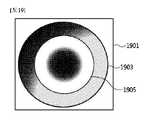
この時、打楽器と類似する形態の周波数構造を有するが、この周波数発振は、クラドニパターン(Chladni Pattern)で説明することができる。 At this time, it has a frequency structure similar to that of a percussion instrument, and this frequency oscillation can be explained by a Chladni pattern.
一般的な倍音構造を有しない衝撃音は、ファンダメンタル(Fundamental)周波数を除去すれば、他のハーモニクス(Harmonics)周波数を併せて除去可能で、全体的なノイズを減衰させることができる。 Impulsive sounds that do not have a general overtone structure can be removed together with other harmonics frequencies by removing the fundamental frequencies, thereby attenuating the overall noise.
また、ハーモニクス周波数に対するノイズ除去は、クラドニパターンを適用できるため、ノイズ減衰特性を向上させることができる。 In addition, since a cladni pattern can be applied to noise removal for harmonic frequencies, noise attenuation characteristics can be improved.
図10を参照して説明すれば、衝撃音は、低域から高域まで広い周波数帯域を有する。
この時、低音は波長が長く、高音は波長が短いため、一般的な波形の分析イメージにおいて長い波長の上に高音に相当する細かい波長が描かれる。Referring to FIG. 10, impulsive sound has a wide frequency band from low to high frequencies.
At this time, since low-pitched sounds have long wavelengths and high-pitched sounds have short wavelengths, detailed wavelengths corresponding to high-pitched sounds are drawn on long wavelengths in a general waveform analysis image.
この時、第1ファンダメンタル周波数値は、最初に発生する波長の長さを求めて得ることができる。 At this time, the first fundamental frequency value can be obtained by calculating the length of the first generated wavelength.
この時、前記第1ファンダメンタル周波数値に相当する逆波長の信号を発生させて原信号と合わせると、低音が消えた第2衝撃音に対する値を得ることができる(1001)。 At this time, by generating a reverse wavelength signal corresponding to the first fundamental frequency value and combining it with the original signal, a value for the second impulsive sound with no bass can be obtained (1001).
この時、同様の方法で第2衝撃音に対する第2ファンダメンタル周波数値を得ることができ、前記第2ファンダメンタル周波数値に相当する波長に逆相をかけて合わせると(1003)、中低音が消えた第3衝撃音に対する値を得ることができる(1005)。 At this time, the second fundamental frequency value for the second impulsive sound can be obtained by the same method, and when the wavelength corresponding to the second fundamental frequency value is reversed (1003), the middle and low sounds disappear. A value for the third impulsive sound can be obtained (1005).
前記衝撃音は、上述した方法を繰り返して平坦化(相殺)することができ、この方法は、フーリエ変換(Fourier Transform)の原理と同一である。 The impulsive sound can be flattened (cancelled) by repeating the above method, which is the same as the Fourier Transform principle.
ただし、この方法は、低域帯の周波数を除去するのに効果的であるが、波長の短い高域帯の周波数を除去することは困難である。これについての方策は後述する。 However, although this method is effective in removing low-band frequencies, it is difficult to remove short-wavelength high-band frequencies. Measures for this will be described later.
図11は、騒音を除去するための許容位相差を示す概念図である。
上述したフーリエ変換方法を用いた騒音除去方法は、相殺のために、ジェネレートされる波長を原信号の逆相と正確に生成しなければならない。FIG. 11 is a conceptual diagram showing a permissible phase difference for removing noise.
Noise cancellation methods using the Fourier transform method described above must produce the generated wavelength exactly as the opposite phase of the original signal for cancellation.
また、逆相を有する相殺用波形において-10dB以上の減衰効果を得るためには、波形の5%範囲以内で逆相が作られなければならない。 Also, in order to obtain an attenuation effect of -10 dB or better in a canceling waveform with antiphase, the antiphase must be produced within 5% of the waveform.

前記数式4を参照すれば、完璧にノイズが除去されるためには、入力波と相殺波が正確な逆相を有すれば良いし、2つの波長の位相差がλ/2になるとよい。 Referring to Equation 4, in order to completely eliminate noise, the input wave and the canceling wave should have exact opposite phases, and the phase difference between the two wavelengths should be λ/2.
この時、逆相が適用された相殺波が入力波と逆相をなす時、波長の5%以内に位置しており、-10dBの騒音減衰特性を有することができる。 At this time, when the canceling wave to which the reversed phase is applied has the reversed phase with the input wave, it is located within 5% of the wavelength and can have a noise attenuation characteristic of -10dB.
すなわち、+/-5%以内の時、相殺効果が大きくなる。
図12は、抽出されたクラドニパターンを示す例示図である。That is, the offsetting effect becomes large when it is within +/-5%.
FIG. 12 is an exemplary diagram showing an extracted Chladni pattern.
図12を参照すれば、層間騒音が放射される領域は、ルームの天井に相当し、ルームの天井を振動膜(Vibrating Membrane)と仮定すれば、クラドニパターンを適用することができる。 Referring to FIG. 12, the area where the inter-layer noise is radiated corresponds to the ceiling of the room, and if the ceiling of the room is assumed to be a vibrating membrane, the Chladni pattern can be applied.
この時、音のハーモニクス構成は、天井面をメンブレンとして干渉と消滅に対するパターンを得て予測することができる。 At this time, the harmonic structure of the sound can be predicted by obtaining patterns for interference and extinction using the ceiling as a membrane.
前記予測された値の使用は、ハーモニクスで構成されない周波数に対するより正確な周波数値を得ることができ、層間材質に対する密度値を定数化してより正確な数値を得ることもできる。 The use of the predicted values can obtain more accurate frequency values for frequencies not composed of harmonics, and constant density values for interlayer materials can also obtain more accurate numerical values.
層間騒音を例に挙げると、天井は長方形構造を有するため、複数の振動モードを有することができ、これは、長方形メンブレンによるハーモニクス生成の構造を把握できるクラドニパターンで説明することができる。 Taking inter-story noise as an example, since the ceiling has a rectangular structure, it can have multiple modes of vibration, which can be described by the Chladni pattern, which allows us to understand the structure of harmonics generation by rectangular membranes.
クラドニパターンの理論は、下記数式5のように一般的な公式で図式化されている。 The theory of the Chladni pattern is illustrated by a general formula as shown in Equation 5 below.

この時、追加的に生成される周波数は、下記数式6で定義することができる。 At this time, the additionally generated frequency may be defined by Equation 6 below.

したがって、クラドニパターンによる騒音除去方法は、予測された値およびパターンの変化を予め認知可能で、前記パターンに相当する逆相の波形をジェネレートして入力される騒音を相殺することができる。 Therefore, the noise elimination method based on the Chladni pattern can recognize the predicted value and pattern change in advance, and can cancel the input noise by generating an antiphase waveform corresponding to the pattern.
図13は、連続する騒音のスペクトルにおいてハーモニクス周波数1303とファンダメンタル周波数1301を示す例示図である。 FIG. 13 is an exemplary diagram showing
一定のパターンを有する連続する騒音は波長を検知し、単純に逆相信号を発生させる方法で除去可能で、衝撃音に比べて騒音除去が容易である。 A continuous noise having a fixed pattern can be eliminated by detecting the wavelength and simply generating an antiphase signal, which is easier to eliminate than the impact sound.
また、一定のパターンを有する連続音は、発振によってハーモニクスを有する騒音が多く、この場合、ファンダメンタル周波数1301を除去するだけで高域帯で発生するハーモニクスによる騒音を併せて除去することができる。 A continuous sound having a certain pattern is often noise having harmonics due to oscillation. In this case, simply removing the
この時、本発明の一実施例による騒音除去方法は、倍音構造を有する騒音除去からファンダメンタル周波数および波長の長さを知ることができれば、当該波形をジェネレートして騒音を除去することができる。 At this time, the noise elimination method according to an embodiment of the present invention can eliminate the noise by generating the corresponding waveform if the fundamental frequency and the length of the wavelength can be known from the noise elimination having the overtone structure.
この時、ファンダメンタルとともにn個に相当するハーモニクス周波数1301を同時にジェネレートすることにより、実際の騒音と類似するオーディオ信号を生成することができる。 At this time, by simultaneously generating n
この時、本発明の一実施例による騒音除去方法は、前記生成された信号に逆相処理をして騒音を除去することができ、これは、フーリエ変換を逆に利用する方法と同様である。 At this time, the noise elimination method according to an embodiment of the present invention can eliminate the noise by inversely processing the generated signal, which is the same as the method of inversely using the Fourier transform. .
この時、連続する音はオーディオサンプルにより効果的に除去することもできる(学習機能)。 At this time, continuous sounds can also be effectively removed by audio samples (learning function).
前記学習機能は、騒音除去装置が適用される場所で発生する騒音を収集してサンプル化し、これをデータベース化して騒音除去の効果を極大化することができる。 The learning function collects and samples the noise generated in the place where the noise canceling device is applied, and creates a database of the samples to maximize the noise canceling effect.
この時、学習機能は、マイクモジュールにより入力される騒音をサンプルとして採取してメモリに格納することができる。これは、騒音除去機能が動作する間に格納するように設定することができる。 At this time, the learning function can sample the noise input by the microphone module and store it in the memory. This can be set to store while the noise cancellation function is running.
この時、採取されたサンプルは、レベル、ディレイ、波長およびスペクトルなどを分析し、分析されたデータは前記サンプルとともに格納可能である。 At this time, the sample taken is analyzed for level, delay, wavelength, spectrum, etc., and the analyzed data can be stored with the sample.
この時、学習機能は、騒音の波長、レベルなどを分析して騒音の原因を把握できるようにし、最も類似する値を有するサンプルをローディングし、逆相を適用して騒音を除去することもできる。 At this time, the learning function can analyze the wavelength, level, etc. of the noise to understand the cause of the noise, load the sample with the most similar value, and apply the reverse phase to remove the noise. .
前記学習機能は、騒音除去において最も重要なサンプルのタイミングを補完するための方法で、波形の形に相当する値をベクトル値として認識し処理することが可能で、オーディオ処理にかかる時間を節約することができ、事実上、ディレイが発生しないプロセスを行うことができる。 The learning function is a method for interpolating the timing of the most important samples in noise reduction, and can recognize and process values corresponding to waveform shapes as vector values, saving time in audio processing. It is possible to have a process that is virtually delay-free.
前記採取されたサンプルは、メモリに格納されるだけでなく、インターネットで連結された管理用サーバに格納されてもよい。 The collected samples may be stored not only in memory but also in a management server connected to the Internet.
この時、サーバに格納されたサンプルは、同一の機器を用いる他のユーザや他の空間のデータとして活用されてもよい。 At this time, the samples stored in the server may be used as data for other users using the same device or other spaces.
この時、供給者は、騒音除去装置において最も効果的に騒音除去が可能となるように、当該サンプルを編集して再アップロードすることができる。 The supplier can then edit and re-upload the sample so that it can be denoised most effectively in the denoise device.
図14は、本発明の一実施例によるマイク内蔵型スピーカ装置の断面図である。
騒音除去方法の基本条件は、騒音が発生する位置と同一の位置で逆相の波長を発生させてこれを相殺させることである。FIG. 14 is a cross-sectional view of a microphone built-in speaker device according to an embodiment of the present invention.
The basic condition of the noise elimination method is to generate opposite-phase wavelengths at the same position as the position where the noise is generated to cancel them out.
この時、騒音源が壁または障害物によって遮断されている場合には、騒音が発生する地点を前記壁または障害物として見なすことができ、前記壁または障害物に逆相の波長を発生させて騒音を消滅させることができる。 At this time, if the noise source is blocked by a wall or obstacle, the point where the noise is generated can be regarded as the wall or obstacle, and the wall or obstacle generates the opposite phase wavelength. noise can be extinguished.
この時、音を再生する装置は、スピーカドライバが使用可能であり、騒音を受音するためのマイクモジュールも要求される。 At this time, a device that reproduces sound can use a speaker driver and requires a microphone module for receiving noise.
この時、マイクモジュールは、騒音を受音し、受音された信号に逆相処理をしてスピーカドライバに伝達し、スピーカドライバは、逆相処理された信号を出力して騒音を消滅させることができる。 At this time, the microphone module receives noise, reverse-phase-processes the received signal, and transmits the signal to the speaker driver, and the speaker driver outputs the reverse-phase-processed signal to eliminate the noise. can be done.
しかし、スピーカドライバを介して再生される音は、マイクモジュールにピックアップされ、ピックアップされた音はアンプを介して増幅し、再度スピーカドライバによって出力される。 However, the sound reproduced through the speaker driver is picked up by the microphone module, the picked up sound is amplified through an amplifier, and is output again by the speaker driver.
これは、ハウリングまたはフィードバックといい、前記フィードバックは、スピーカドライバのボイスコイルを基準として正面(On-Axis)にマイクモジュールが位置する場合に発生しやすい。 This is called howling or feedback, and the feedback is likely to occur when the microphone module is positioned on-axis with respect to the voice coil of the speaker driver.
したがって、一般的に、スピーカドライバとマイクモジュールは、同一の位置に設けられない。 Therefore, typically the speaker driver and the microphone module are not co-located.
それだけでなく、前記フィードバックは、アンプの増幅量を持続的に増加させて、アンプ回路、電源回路およびスピーカドライバの損傷を発生させたりもする。 In addition, the feedback continuously increases the amplification of the amplifier, causing damage to the amplifier circuit, power supply circuit and speaker driver.
前記フィードバックは、特定の周波数で生成されやすく、Q(Quality factor)値の帯域幅が広くなるにつれて、周波数の全帯域に影響を及ぼしうる。 The feedback tends to be generated at a specific frequency and can affect the entire band of frequencies as the bandwidth of the Q (Quality factor) value increases.
したがって、グラフィックEQ(Equalizer)を用いてフィードバックが発生する周波数を遮断する方法などにより前記フィードバックを防止する方法が必要である。 Therefore, there is a need for a method of preventing the feedback by using a graphic EQ (Equalizer) to cut off the frequency at which the feedback occurs.
しかし、上述した方法は、周波数の特性を変形させて、入力される周波数の逆相を正確に処理できないので、騒音除去環境で使用が困難という問題点がある。 However, the above-described method deforms the frequency characteristic and cannot accurately process the reverse phase of the input frequency.
また、フィードバックを防止するために、マイクモジュールとスピーカドライバを別個の位置に設けた場合には、マイクモジュールにより除去しようとする騒音を正確にピックアップできないだけでなく、DSP(Digital Signal Processor)などにより補正しなければならないという困難がある。 In addition, if the microphone module and the speaker driver are provided in separate positions to prevent feedback, the noise to be removed by the microphone module cannot be accurately picked up, and a DSP (Digital Signal Processor) or the like cannot pick up the noise. There are difficulties that must be corrected.
前記フィードバックは、スピーカドライバとマイクモジュールがすべて一定の指向性を有しているゆえに発生し、前記フィードバックを防止するために、スピーカドライバおよびマイクモジュールをOff-Axis状態に位置させることが有利である。 Said feedback occurs because the speaker driver and microphone module all have constant directivity, and it is advantageous to position the speaker driver and microphone module in the Off-Axis state to prevent said feedback. .
しかし、Off-Axis状態は、上述のように正確な音をピックアップできず、On-Axis状態に位置させかつ、フィードバックを防止できる方法が必要である。 However, the Off-Axis state cannot pick up the correct sound as described above, and a method is needed to place the device in the On-Axis state and prevent feedback.
そこで、本発明の一実施例は、On-Axis上でもフィードバックを防止するために磁場を遮断可能なカバーをマイクモジュールのカバーとして用い、スピーカドライバの振動板の内部に前記マイクモジュールを位置させることによりフィードバックを防止することができる。 Therefore, in one embodiment of the present invention, a cover capable of blocking a magnetic field is used as the cover of the microphone module to prevent feedback even on the On-Axis, and the microphone module is positioned inside the diaphragm of the speaker driver. can prevent feedback.
図14を参照すれば、本発明の一実施例によるマイク内蔵型スピーカ装置は、媒質から音を受音して受音信号を生成するマイクモジュール1401と、前記受音信号の逆相信号に相応する振動を前記媒質に伝達するスピーカドライバ1403と、前記マイクモジュール1401から前記受音信号を受信して、前記受音信号の逆相信号を生成し、前記逆相信号を前記スピーカドライバ1403に伝達するコントローラとを含むことができる。 Referring to FIG. 14, a speaker device with a built-in microphone according to an embodiment of the present invention includes a
この時、前記マイクモジュール1401は、高音用コンタクトマイク、低音用コンタクトマイク、高音用ブーストプレート、低音用ブーストプレート、ラバープレートおよびフィードバック遮断ハウジングなどを含むことができる。 At this time, the
この時、前記スピーカドライバ1403は、磁石、ボイスコイル、振動部および固定ブラケットなどを含むことができる。 At this time, the
この時、本発明の一実施例は、空間騒音を効率的に除去するために、マイクモジュール1401の位置と同一の位置にスピーカドライバ1403を装着することができる。 At this time, an embodiment of the present invention can mount the
マイクモジュール1401と同一の位置にスピーカドライバ1403を装着する理由は、ピックアップ位置と再生位置とを同一にすることで、同一でない位置にある場合に発生しうる位相差を補正するためのプロセッシングのパワーを低減し、誤差を最小化するためである。 The reason why the
そのために、本発明の一実施例は、振動を作り出すためのスピーカドライバ1403の内部にマイクモジュール1401を配置し、フィードバック防止構造を適用して、騒音信号をピックアップしながら、同時に逆相の信号を再生できる1つの装置を提示することができる。 To that end, one embodiment of the present invention places the
より詳しくは、前記スピーカドライバ1403の振動部は、パラボラ形状を有することができ、その内部に高音と低音を分離してピックアップできるマイクモジュール1401が搭載可能である。 More specifically, the vibrating portion of the
この時、前記マイクモジュール1401は、スピーカドライバ1403の振動に影響を受けないように構造的に分離される。 At this time, the
より詳しくは、前記スピーカドライバ1403の振動部は、前記媒質に接触する一側面に内部に陥没したマイク収容部を含むことができ、前記マイクモジュール1401は、前記マイク収容部に振動部と離隔して位置することができる。 More specifically, the vibrating part of the
また、前記スピーカドライバ1403の振動が前記マイクモジュール1401に伝達されないように、一端が前記マイクモジュール1401と固定結合され、中段が前記スピーカドライバ1403と結合されるマイクモジュール支持用ポールをさらに含み、前記マイクモジュール支持用ポールと前記スピーカドライバ1403との間にゴムリングを介在させることができる。 In addition, a microphone module supporting pole whose one end is fixedly coupled to the
上述した構造により、本発明の一実施例は、マイクモジュール1401とスピーカドライバ1403が前記媒質に正確に載置されて、ピックアップおよび再生が完全に独立して動作するように配置および運営できる。 Due to the structure described above, one embodiment of the present invention can be arranged and operated such that the
また、マイクモジュール支持用ポールは、マイクモジュール1401が媒質に正確に吸着できるようにし、ラバープレートに接着剤を用いて目的とする媒質に強固に付着することもできる。 In addition, the microphone module support pole allows the
この時、フィードバック遮断ハウジングは、高音用コンタクトマイクおよび低音用コンタクトマイクを収容しかつ、外部磁気の影響を防止するために防磁性素材(防磁型)で形成され、受音率を向上させるためにパラボラ形状に形成される。 At this time, the feedback blocking housing accommodates the high-frequency contact microphone and the low-frequency contact microphone and is made of anti-magnetic material (anti-magnetic type) to prevent the influence of external magnetism. It is formed in a parabolic shape.
また、本発明の一実施例は、スピーカドライバ1403およびマイクモジュール1401の連結のための統合端子を含むことができる。 An embodiment of the present invention may also include integrated terminals for connection of
この時、前記マイクモジュール1401は、高音用コンタクトマイクおよび低音用コンタクトマイクのように互いに異なるサイズのピエゾダイヤフラムを用いて、受音しようとする中心周波数を互いに異なるようにピックアップすることができる。 At this time, the
これにより、目的とする受音周波数帯域の範囲を広げることができる。
また、本発明の一実施例は、スピーカドライバ1403が装着された同一の位置に受音用マイクモジュール1401が装着されるが、前記マイクモジュール1401は、コンタクトマイク(例えば、ピエゾマイク)を用いて空気中の騒音は受音せず、密着面に対する騒音のみを受音してフィードバックを防止することができる。This makes it possible to widen the range of the target sound receiving frequency band.
Also, in one embodiment of the present invention, a sound receiving
さらに、上述のように、前記マイクモジュール1401は、防磁型のフィードバック遮断ハウジングを含むことで、スピーカドライバ1403の磁場が影響を及ぼさないようにすることが可能で、磁場によるフィードバックも防止することができる。 Further, as described above, the
この時、振動部は、磁石と連結されており、ムービングマグネチック方式の駆動により振動部を介して媒質に振動を伝達することができる。 At this time, the vibrating part is connected to the magnet, and the vibration can be transmitted to the medium through the vibrating part by moving magnetic type driving.
この時、振動部の振動は、前記ゴムリングによってマイクモジュール1401に何ら影響も及ばない。 At this time, the vibration of the vibration part does not affect the
この時、固定ブラケットは、スピーカドライバ1403のボイスコイル固定部またはスピーカドライバ1403の外部ハウジングと連結されて前記媒質に固定される。 At this time, the fixing bracket is connected to the voice coil fixing portion of the
この時、マイクモジュール1401と振動部は、固定ブラケットによって前記媒質に水平に装着される。 At this time, the
図15は、本発明の一実施例により直接音と間接音を区分して除去する概念図である。
図15を参照すれば、本発明の一実施例による騒音除去方法は、複数のマイクをアレイ形式で一定の距離をおいて設け、前記マイクにより受音すれば、音源の方向と音源との距離を算出することができる。FIG. 15 is a conceptual diagram of separating and removing direct sound and indirect sound according to an embodiment of the present invention.
Referring to FIG. 15, in the noise reduction method according to an embodiment of the present invention, a plurality of microphones are arranged in an array at a certain distance, and if the microphones receive sound, the direction of the sound source and the distance from the sound source are can be calculated.
この時、騒音の発生位置とスピーカの再生位置とが同一の場合、逆相により簡単にキャンセリングが可能であるが、騒音の発生位置とスピーカの再生位置とが異なる場合には、逆相によるキャンセリングが不可能で、むしろ干渉を起こすことがある。 At this time, when the noise generation position and the speaker reproduction position are the same, cancellation is easily possible by reverse phase, but when the noise generation position and the speaker reproduction position are different, reverse phase cancellation is possible. Cancellation is not possible, rather interference may occur.
したがって、騒音源の位置検出は、距離および方向成分を追加して逆波長を正確に作り出すようにする。 Therefore, noise source localization adds range and direction components to accurately produce the reverse wavelength.
また、本発明の一実施例による騒音除去方法は、複数のスピーカを用いて周波数毎に分離された波長を異ならせることができ、スピーカ毎に互いに異なるディレイ値および互いに異なる波長をジェネレートすることができて、精巧なノイズ除去が可能である。 In addition, the noise elimination method according to an embodiment of the present invention can use a plurality of speakers to make the separated wavelengths different for each frequency, and generate different delay values and different wavelengths for each speaker. and sophisticated noise removal is possible.
この時、天井1500を例に挙げて説明すれば、音源1501から発生した衝撃音1503は、騒音除去装置に直接伝達されてもよく、反射(1505)して伝達されてもよい。 At this time, taking the
この時、直接音1503は、音源と最も近いスピーカドライバ1509によって除去可能であり、間接音1505または反射音は、残りのスピーカドライバ1511によって除去可能である。 At this time, the
より詳しく説明すれば、騒音除去方法は、受音の基準となるリファレンスマイクモジュールを装置の中心におき、n個のマイクモジュールを一定の距離をおいて配置することができる。 More specifically, the noise elimination method can place a reference microphone module, which serves as a standard for receiving sound, at the center of the device, and arrange n microphone modules at regular intervals.
この時、リファレンスマイクモジュールとn個のマイクモジュールは、スペクトルアナライザにより波形を細部的に分析した後、位相、ディレイ、レベルを基準として分離された値を演算して騒音の発生位置と距離を検知することができる。 At this time, the reference microphone module and n microphone modules analyze the waveform in detail with a spectrum analyzer, and then calculate the separated values based on the phase, delay, and level to detect the location and distance of noise generation. can do.
この時、検知された位置で発生した騒音を除去するために再生されるスピーカドライバは、位相制御および自動ゲイン制御器を用いて衝撃ポイントの音を遮断できるようにマトリクス化して、n個のスピーカで分割再生することができる。 At this time, the speaker driver, which is reproduced to eliminate the noise generated at the detected position, is matrixed so that the sound of the impact point can be blocked using the phase control and the automatic gain controller, and n speakers can be divided and played back.
この時、本発明の一実施例による騒音除去方法は、騒音源の位置と方向値を演算できるため、反射によって流入したり、発振、回折、干渉などによる変形値を知ることができて、追加的なプロセッシングがより容易になる。 At this time, since the noise elimination method according to an embodiment of the present invention can calculate the position and direction of the noise source, it is possible to know the deformation value due to the influx by reflection, oscillation, diffraction, interference, etc., and add processing becomes easier.
また、間接音は、直接音に比べてディレイをもたせることにより、直接音と間接音との差を区分することができ、それによる騒音除去方法が異なって適用可能で騒音除去の効率を高めることができる。 In addition, the indirect sound has a delay compared to the direct sound, so that the difference between the direct sound and the indirect sound can be distinguished, so that different noise removal methods can be applied and the efficiency of noise removal can be improved. can be done.
図16は、本発明の一実施例により目的とする周波数を分離して除去するフローチャートである。 FIG. 16 is a flowchart for isolating and removing frequencies of interest according to one embodiment of the present invention.
図16を参照すれば、本発明の一実施例による騒音除去方法は、まず、MICROPHONEにより受音信号が入力される。 Referring to FIG. 16, in the noise elimination method according to an embodiment of the present invention, first, a received sound signal is input from a MICROPHONE.
この時、GATEは、周辺の騒音の平均値を適用して動作点を決定することができる。
この時、LOUDNESS LEVEL DETECTOR/COMPARISONは、マイクプリアンプにより入力された受音信号と、パワーアンプの出力とを比較して自動ゲインコントロールを調整することができる。At this time, GATE can apply the average value of ambient noise to determine the operating point.
At this time, the LOUDNESS LEVEL DETECTOR/COMPARISON can adjust the automatic gain control by comparing the received sound signal input by the microphone preamplifier and the output of the power amplifier.
この時、FILTERは、プロセッシングを目標とする実効周波数帯域のみを選択することができ、特定の周波数値が指定されたLPF(Low Pass Filter)およびHPF(High Pass Filter)が適用されてもよい。 At this time, FILTER can select only the effective frequency band targeted for processing, and LPF (Low Pass Filter) and HPF (High Pass Filter) with specific frequency values may be applied.
この時、CROSSOVERは、周波数をプロセッシングの目的に合わせて分離することができ、BPF(Band Pass Filter)が適用されてもよい。 At this time, CROSSOVER can separate frequencies according to the purpose of processing, and a BPF (Band Pass Filter) may be applied.
この時、BAND1、BAND2、BAND N PHASE PROCESSORは、目標とする除去周波数に応じて中心周波数を設定し、それぞれ中心周波数に対する位相をディレイを用いて補正し、必要および正確度に応じてN個に細分してもよい。 At this time, the BAND1, BAND2, and BAND N PHASE PROCESSOR set the center frequency according to the target removal frequency, correct the phase with respect to the center frequency using a delay, and divide the number into N according to the necessity and accuracy. You can subdivide.
この時、BAND1、BAND2、BAND N TRIMMERは、それぞれの中心周波数の位相補正によるレベル補償を再度設定し、必要および正確度に応じてN個に細分してもよい。 At this time, BAND1, BAND2, and BAND N TRIMMER may be re-set level compensation by phase correction of each center frequency, and may be subdivided into N according to necessity and accuracy.
この時、SUMMERは、逆相処理された信号を再度合算することができ、POWER AMPLIFIERおよびSPEAKER DRIVERを介して騒音を除去することができる。 At this time, SUMMER can resum the phase-reversed signals and remove the noise through the POWER AMPLIFIER and SPEAKER DRIVER.
この時、TRANSIENT DETECTOR/FEEDBACK DESTROYERは、入力される信号がトランシエント特性を有するか、フィードバックを有するかをプロセッシングし、急激な信号の変化はトランシエント特性を有するものと認識し、徐々に増加する信号はフィードバックとして見なして、ゲーティングをかけて信号成分を削除することができる。 At this time, the TRANSIENT DETECTOR/FEEDBACK DESTROYER processes whether the input signal has transient characteristics or has feedback, recognizes a rapid signal change as having transient characteristics, and gradually increases The signal can be viewed as feedback and gated to remove signal components.
また、TRANSIENT DETECTOR/FEEDBACK DESTROYERは、ADSRの特性を用いて信号の種類を鑑別することができる。これにより、フィードバックが発生する周波数を予め確認可能で、フィードバックを完璧に制御することができる。 Also, the TRANSIENT DETECTOR/FEEDBACK DESTROYER can discriminate the type of signal using the characteristics of the ADSR. This allows the frequency at which feedback occurs to be known in advance, and the feedback to be perfectly controlled.
図17は、本発明の一実施例によるトランスオーラル(Transaural)騒音を除去する例示図である。 FIG. 17 is an exemplary diagram of removing transaural noise according to one embodiment of the present invention.
本発明の一実施例による騒音除去方法は、騒音除去装置が付着した媒質外から衝撃音が流入しうるため、完璧な騒音除去は難しいことがある。 In the noise elimination method according to an embodiment of the present invention, it may be difficult to completely eliminate the noise because the impulsive sound may flow in from outside the medium to which the noise elimination device is attached.
高音に対する除去は、上述のようにハニカムレゾネータを用いて一部除去できるが、騒音除去装置が付着していない方向から騒音が流入することがある。 High-pitched sounds can be partially removed by using a honeycomb resonator as described above, but noise may flow in from directions where the noise removing device is not attached.
したがって、騒音除去装置が付着した媒質と反対方向に向かって装着されるスピーカドライバを介してトランスオーラル再生を行うことができる。 Therefore, transaural reproduction can be performed through the speaker driver mounted in the direction opposite to the medium to which the noise eliminator adheres.
この時、媒質ではない空間で発生する騒音は、別のピックアップマイクにより予め予測可能であり、騒音除去装置は、これに相当する逆相のトランスオーラル信号を発生させて特定の空間に対する騒音を除去することができる。 At this time, the noise generated in the space other than the medium can be predicted in advance by another pickup microphone, and the noise elimination device generates a transaural signal of opposite phase corresponding to this to eliminate the noise for the specific space. can do.
この時、騒音除去装置は、リファレンスマイクとN個のピエゾマイクにより入力された信号を分析して、仮想の聴取点を基準として波形の進行をシミュレーションすることができる。 At this time, the noise canceller can analyze the signals input from the reference microphone and the N piezoelectric microphones and simulate the progress of the waveform based on the virtual listening point.
この時、聴取者の位置は、人体検知センサを用いて把握可能であり、把握されたデータは、ポジションコントローラに伝達される。 At this time, the listener's position can be grasped using the human body detection sensor, and the grasped data is transmitted to the position controller.
この時、前記聴取者の位置は、トランスオーラルを用いて騒音を除去する領域になり得る。 At this time, the listener's position may be an area where noise is removed using transaural.
DSPを経てプロセッシングが適用されたデータは、トランスオーラルプロセッサを介して前面のスピーカに伝達される。 The processed data through the DSP is transmitted to the front speaker through the transaural processor.
この時、聴取点を基準とするノイズ除去用トランスオーラル信号が発生し、聴取点での騒音は相殺できる。 At this time, a noise-removing transaural signal is generated with the listening point as a reference, and the noise at the listening point can be canceled.
ただし、この時、聴取点のノイズ除去の程度は、ユーザが有無線装置によりコントロールすることができる。 However, at this time, the degree of noise removal at the listening point can be controlled by the user using the wired/wireless device.
この時、多数の聴取者が存在する時の聴取点は、有無線装置により適正地点に指定される。 At this time, the listening point when there are many listeners is designated as an appropriate point by the wired/wireless device.
図17を参照すれば、騒音除去方法は、騒音が発生する地点1701から聴取点までの距離をLと指定すれば、一般的な状況でLまで伝達する音波を予測することができる。これに追加的に、他の媒質または壁面を通して流入する騒音の量とディレイ、波長などの要素を追加すれば、聴取点で音波がどのように形成されるかを予測することができる。 Referring to FIG. 17, if the distance from the
結果的に、騒音除去方法は、前記予測値をトランスオーラルプロセッサのパラメータとして用いて騒音を除去することができる。 Consequently, the noise cancellation method can use the predicted values as parameters of the transaural processor to cancel the noise.
この時、トランスオーラルスピーカ1703はそれぞれ、1個以上のスピーカアレイで構成され、聴取点を基準とするトランスオーラルサウンドイメージを生成することができる。 At this time, each
また、トランスオーラルサウンドイメージが適用される地域を拡張させるために、複数のトランスオーラルスピーカセットを装置に装着することができる。 In addition, multiple transaural speaker sets can be attached to the device in order to expand the area where the transaural sound image is applied.
図18は、本発明の一実施例により多重マイクで騒音を除去するフローチャートである。 FIG. 18 is a flowchart for removing noise with multiple microphones according to one embodiment of the present invention.
図18を参照すれば、多重マイクは、立体音響を習得するためのマイキング方法により1つ以上で構成される。 Referring to FIG. 18, multiple microphones are composed of one or more according to a miking method for acquiring stereophonic sound.
例えば、BIBAURALは2個、AMBISONICは4個以上、多重XYは8個以上で構成される。 For example, there are two BIBAURALs, four or more AMBISONICs, and eight or more multiplex XY.
この時、MIC PREおよびADを通過した受音信号は、1kHz以下の周波数を除去するHPF(High Pass Filter)を通過してMIXERに伝達することができる。 At this time, the received sound signal that has passed through the MIC PRE and AD can be transmitted to the MIXER after passing through a HPF (High Pass Filter) that removes frequencies of 1 kHz or less.
この時、MIXERは、PANNING、LEVELなどによりバスを介して入力された受音信号を処理することができる。 At this time, the MIXER can process the received sound signal input through the bus according to PANNING, LEVEL, and the like.
この時、DSPは、COMPRESSOR、GATE、EQなどを介してオーディオDSP処理を行うことができる。 At this time, the DSP can perform audio DSP processing through COMPRESSOR, GATE, EQ, and the like.
この時、BINAURAL/AMBISONIC ENCODERは、最終処理されたオーディオに対するモニタリングを行い、立体音響受音方法でエンコーディングを適用することができる。 At this time, the BINAURAL/AMBISONIC ENCODER can monitor the final-processed audio and apply encoding using the stereophonic sound reception method.
この時、PHASE ANALYZERは、エンコーディングされたデータとトランスオーラルデコーディングとの間の位相を分析して正確にマッチングさせることができる。 At this time, the PHASE ANALYZER can analyze and accurately match the phase between the encoded data and the transaural decoding.
この時、PHASE CONTROLLERは、分析されたアナライザを介して逆相を適用することができる。 At this time, the PHASE CONTROLLER can apply reverse phase through the analyzed analyzer.
この時、バイノーラルまたはアンビソニックで処理された信号は、TRANSAURAL DECODER、POWER AMPおよびSPEAKERを介してトランスオーラルで再生できる。 At this time, the binaural or ambisonic processed signal can be transaurally reproduced through TRANSAURAL DECODER, POWER AMP and SPEAKER.
図19は、本発明の一実施例によりディスプレイ装置を介して動作状態を示す例示図である。 FIG. 19 is an exemplary diagram showing operating states through a display device according to an embodiment of the present invention.
騒音除去装置は、層間騒音が発生した時、騒音はユーザに伝達されないようにしかつ、当該機器が動作しているかを確認することができる。 When inter-story noise occurs, the noise eliminator can prevent the noise from being transmitted to the user and check whether the device is working.
また、機器の動作状態は、時間および日付毎に記録されて層間騒音の頻度を確認することができ、このようなデータを活用してユーザの環境に合わせて適用することもできる。 In addition, the operating state of the equipment is recorded by time and date, and the frequency of inter-story noise can be checked, and such data can be applied according to the user's environment.
図19を参照すれば、騒音除去装置は、多重に区分されるディスプレイ1901を含み、区分されたディスプレイ1901を介して直接音の処理の有無および間接音の処理の有無などを表示することができる。 Referring to FIG. 19, the noise canceling apparatus includes a
この時、直接音の処理モニタは、内部の円1905であり、中心を基準としてノイズ除去が適用される量を表現することができ、処理される方向性を有することができる。 At this time, the processing monitor of the direct sound is the
この時、間接音を処理するモニタは、外部の円1903であり、外部から中心にノイズ除去される量を表現することができ、処理される方向性を認知することができる。 At this time, the monitor that processes the indirect sound is the
前記ディスプレイ方法は上述した例示に限定されず、ユーザの設定によって色相およびディスプレイの点灯の有無に変更することができる。 The display method is not limited to the above example, and the hue and whether or not the display is turned on can be changed according to the user's settings.
この時、騒音除去装置の動作状態は、時間によって記録をし、ユーザはディスプレイやスマートフォンを用いて動作状態をモニタすることができ、前記記録を時間、日、月、年などの単位で確認することができる。 At this time, the operating state of the noise eliminator is recorded according to time, and the user can monitor the operating state using a display or a smart phone, and check the record in units of hours, days, months, years, etc. be able to.
この時、前記記録は、機器の動作品質を高めるためのデータとして使用できる。例えば、発生程度の最大値と最小値とを比較し、平均値を知っていれば、機器の動作をより精密に維持できるThreshold、Gatingパラメータとして用いることもできる。 The records can then be used as data to improve the operational quality of the device. For example, if the maximum and minimum values of occurrence are compared and the average value is known, it can be used as Threshold and Gating parameters that can more precisely maintain the operation of the device.
また、前記記録は、層間騒音トラブルによる証拠用資料として用いられてもよい。
さらに、騒音除去装置は、ユーザが留守の時間には動作を中止したり、層間騒音が集中する時間には動作を持続的に行える電源管理システムのデータとしても使用可能である。Also, the record may be used as a documentary evidence for inter-story noise trouble.
Furthermore, the noise eliminator can be used as data for a power supply management system that stops operation when the user is away, or allows continuous operation during times when inter-story noise is concentrated.
図20は、本発明の一実施例により多重マイク2001を介して音源2000の位置を算出する概念図であり、図21は、本発明の一実施例により音源2000の位置を算出するフローチャートである。 FIG. 20 is a conceptual diagram of calculating the position of the
図20および図21を参照すれば、本発明の一実施例は、2個以上のマイク2001を用いてマイク間のレベルを分析して音の発生した方向を算出することができる。 Referring to FIGS. 20 and 21, one embodiment of the present invention uses two or
また、本発明の一実施例は、2個以上のマイク2001を用いてマイク間の時間差を分析して音の発生した距離を算出することができる。 Also, one embodiment of the present invention can calculate the distance from which the sound is generated by using two or
この時、本発明の一実施例は、特定の媒質(天井など)から発生する音に制限すれば、より正確な動作が行われる。 At this time, an embodiment of the present invention operates more accurately by restricting sounds generated from a specific medium (ceiling, etc.).
図22は、本発明の一実施例によりマイクの位置によって騒音処理を区分する概念図である。 FIG. 22 is a conceptual diagram of classifying noise processing according to microphone positions according to an embodiment of the present invention.
図22を参照すれば、騒音除去方法は、音源の方向と距離によって当該波形に対する逆相を音源2201と最も近いスピーカドライバ2203を介して出力することができる。 Referring to FIG. 22, the noise elimination method can output the opposite phase of the corresponding waveform through the
この時、B ZONEは、発生音源との距離または波長の演算エラーによって干渉が発生しうる。 At this time, the B zone may cause interference due to a distance from the sound source or an error in wavelength calculation.
したがって、この時、音源と最も近いスピーカドライバを除いた残りのスピーカドライバは、干渉を抑制するための位相の変形を加えたオーディオ信号を出力することができ、これにより、A ZONEに限って騒音が流入しないように防止することができる。 Therefore, at this time, the remaining speaker drivers excluding the speaker driver closest to the sound source can output an audio signal with a modified phase for suppressing interference. can be prevented from entering.
したがって、本発明の一実施例による騒音除去方法は、複数のスピーカを用いることで、音の拡散にもかかわらずより平坦化された波形を作り出すことができる。 Therefore, the noise cancellation method according to one embodiment of the present invention can use multiple speakers to create a flatter waveform despite the sound diffusion.
図23は、本発明の一実施例による騒音除去方法のフローチャートである。
図23を参照すれば、本発明の一実施例による騒音除去方法は、まず、騒音除去装置により騒音を除去する方法において、受音用マイクモジュールにより媒質から音を受音してノイズ受音信号を生成する(S2310)。FIG. 23 is a flowchart of a noise cancellation method according to one embodiment of the present invention.
Referring to FIG. 23, in the method of removing noise according to an embodiment of the present invention, first, in the method of removing noise using a noise removing device, sound is received from a medium by a microphone module for sound reception, and a received noise signal is obtained. is generated (S2310).
また、本発明の一実施例による騒音除去方法は、前記ノイズ受音信号に基づいてノイズ除去信号を生成する(S2320)。 Also, in the noise elimination method according to an embodiment of the present invention, a noise elimination signal is generated based on the received noise signal (S2320).
さらに、本発明の一実施例による騒音除去方法は、スピーカドライバを介して前記ノイズ除去信号に相応する振動を前記媒質に伝達する(S2330)。 Further, in the noise elimination method according to an embodiment of the present invention, vibration corresponding to the noise elimination signal is transmitted to the medium through a speaker driver (S2330).
この時、前記受音用マイクモジュールは、前記媒質に複数付着し、前記ノイズ除去信号を生成するステップS2320は、複数の受音用マイクモジュールから受音されたノイズ受音信号を用いてノイズに相応する方向を検知し、前記方向に基づいて前記ノイズ除去信号を生成することができる。 At this time, a plurality of the sound receiving microphone modules are attached to the medium, and the step S2320 of generating the noise-removed signal is to reduce the noise using the noise sound signals received from the plurality of sound receiving microphone modules. A corresponding direction can be detected and the denoised signal can be generated based on the direction.
この時、ステップS2320は、前記ノイズ受音信号に基づいて前記ノイズに相応する音源の位置を算出するステップと、前記音源の位置に基づいて前記ノイズ除去信号を生成するステップとを含むことができる。 At this time, step S2320 may include calculating a position of a sound source corresponding to the noise based on the received noise signal, and generating the noise-removed signal based on the position of the sound source. .
前記スピーカドライバは、複数備えられ、前記複数のスピーカドライバそれぞれと前記音源との間の距離を算出するステップと、前記距離の少なくとも1つに相応するディレイを前記複数のスピーカドライバの少なくとも1つに相応するノイズ除去信号に適用するステップとをさらに含むことができる。 a step of: calculating a distance between each of the plurality of speaker drivers and the sound source; and providing a delay corresponding to at least one of the distances to at least one of the plurality of speaker drivers. applying to the corresponding denoised signal.
この時、ステップS2330は、前記複数のスピーカドライバの一部を介して前記音源に相応するノイズを除去するための前記ノイズ除去信号に相応する振動を前記媒質に伝達するステップと、前記複数のスピーカドライバの他の一部は前記振動を減衰させるための減衰振動を前記媒質に伝達するステップとを含むことができる。 At this time, step S2330 includes transferring vibration corresponding to the noise reduction signal to the medium through a portion of the plurality of speaker drivers to remove noise corresponding to the sound source; Another part of the driver may include transmitting a damped vibration to said medium for damping said vibration.
この時、前記受音用マイクモジュールおよび前記スピーカドライバを収容するハニカムレゾネータを介して、前記スピーカドライバの後面で発生する漏音(Sound leakage)および騒音を除去するステップをさらに含むことができる。 At this time, the method may further include removing sound leakage and noise generated behind the speaker driver through a honeycomb resonator accommodating the sound receiving microphone module and the speaker driver.
この時、前記ハニカムレゾネータは、内部がハニカム構造に区分されかつ、1つ以上のハニカム構造を1つの空間に区分する隔壁が形成される。 At this time, the honeycomb resonator is divided into honeycomb structures inside, and partition walls are formed to divide one or more honeycomb structures into one space.
この時、前記ハニカムレゾネータは、内部に吸収された騒音の乱反射を増加させるために、内部に形成された各ハニカム構造の底面の高さが異なって形成される。 At this time, the honeycomb resonator is formed such that the height of the bottom surface of each honeycomb structure formed therein is different in order to increase diffuse reflection of noise absorbed inside.
この時、前記隔壁は、前記隔壁で形成された空間で除去しようとする周波数に対応する大きさの貫通口が形成される。 At this time, the partition is formed with a through hole having a size corresponding to a frequency to be removed in the space formed by the partition.
この時、ステップS2320は、前記ノイズ受音信号に基づいて第1ファンダメンタル(Fundamental)周波数値を算出するステップと、前記第1ファンダメンタル周波数値に対応する第1ノイズ除去信号を生成するステップと、前記第1ファンダメンタル周波数値に相応する波長が除去されたノイズ受音信号に基づいて第2ファンダメンタル周波数値を算出するステップと、前記第2ファンダメンタル周波数値に対応する第2ノイズ除去信号を生成するステップとを含むことができる。 At this time, step S2320 includes: calculating a first fundamental frequency value based on the received noise signal; generating a first noise-removed signal corresponding to the first fundamental frequency value; calculating a second fundamental frequency value based on the received noise signal from which the wavelength corresponding to the first fundamental frequency value has been removed; and generating a second noise-removed signal corresponding to the second fundamental frequency value. can include
この時、ステップS2330は、前記スピーカドライバを介して前記第1ノイズ除去信号および前記第2ノイズ除去信号に相応する振動を順次に前記媒質に伝達することができる。 At this time, step S2330 may sequentially transmit vibrations corresponding to the first noise elimination signal and the second noise elimination signal to the medium through the speaker driver.
この時、ステップS2320は、ユーザによって入力された前記媒質の構造情報に応じて、クラドニパターン(Chladni pattern)を予測するステップと、前記パターンおよび前記ノイズ受音信号に基づいて前記ノイズ除去信号を生成するステップとを含むことができる。 At this time, step S2320 includes predicting a Chladni pattern according to the structural information of the medium input by the user; generating.
この時、ステップS2320は、前記ノイズ受音信号に基づいてファンダメンタル(Fundamental)周波数値およびハーモニクス(Harmonics)周波数値を算出するステップと、前記ファンダメンタル周波数値および前記ハーモニクス周波数値に相応する波形を同時に生成するステップと、前記波形に基づいて前記ノイズ除去信号を生成するステップとを含むことができる。 At this time, step S2320 includes calculating a fundamental frequency value and a harmonics frequency value based on the received noise signal, and simultaneously generating waveforms corresponding to the fundamental frequency value and the harmonics frequency value. and generating the denoised signal based on the waveform.
本発明の一実施例による騒音除去装置は、建物を支持する壁や天井に付着して使用可能で、建物の揺れを比較的容易に検知することができる。 A noise eliminator according to an embodiment of the present invention can be attached to walls and ceilings that support a building and can be used to detect shaking of the building relatively easily.
したがって、本発明の一実施例による騒音除去装置は、地震を検知できるセンサを付加して、地震の発生時にユーザに知らせる機能を提供することもできる。 Therefore, the noise canceling apparatus according to an embodiment of the present invention may be provided with a sensor capable of detecting an earthquake to provide a function of notifying the user when an earthquake occurs.
この時、本発明の一実施例による騒音除去装置は、地震などの異常振動が検知されると、アラームを鳴らし、非常センサ灯を点灯することもでき、状況の終了時、ユーザの設定によって動作をリセットすることもできる。 At this time, the noise eliminator according to an embodiment of the present invention can sound an alarm and turn on an emergency sensor light when an abnormal vibration such as an earthquake is detected, and can operate according to the user's settings when the situation ends. can also be reset.
また、本発明の一実施例による騒音除去装置は、温度、湿度、酸素密度、粒子状物質濃度、火災検知、ガス検知センサを1つ以上含むことができ、これにより、異常状況の発生時、ユーザに視覚または聴覚などユーザが認知できるようにアラームをし、火災発生などのような応急状況には消防装置と連動して非常状況を直ちに消防署に伝達することもできる。 In addition, the noise eliminator according to an embodiment of the present invention may include at least one sensor for temperature, humidity, oxygen density, particulate matter density, fire detection, and gas detection, so that when an abnormal situation occurs, An alarm can be given to the user so that the user can recognize it visually or audibly, and in an emergency situation such as a fire outbreak, the emergency situation can be immediately transmitted to the fire department in conjunction with a fire extinguisher.
図24は、本発明の一実施例によるコンピュータシステムを示す図である。
図24を参照すれば、本発明の一実施例による騒音除去装置の少なくとも一部の構成は、コンピュータで読取可能な記録媒体のようなコンピュータシステム700で実現できる。図24に示すように、コンピュータシステム700は、バス720を介して互いに通信する1つ以上のプロセッサ710と、メモリ730と、ユーザインターフェース入力装置740と、ユーザインターフェース出力装置750と、ストレージ760とを含むことができる。また、コンピュータシステム700は、ネットワーク780に連結されるネットワークインターフェース770をさらに含むことができる。プロセッサ710は、中央処理装置またはメモリ730やストレージ760に格納されたプロセッシングインストラクションを実行する半導体装置であってもよい。メモリ730およびストレージ760は、多様な形態の揮発性または不揮発性記憶媒体であってもよい。例えば、メモリは、ROM731やRAM732を含むことができる。FIG. 24 is a diagram illustrating a computer system according to one embodiment of the invention.
Referring to FIG. 24, at least part of the configuration of the noise canceling apparatus according to one embodiment of the present invention can be implemented in a
以上、本発明による騒音除去装置および方法は上記のように説明した実施例の構成と方法が限定されて適用できるのではなく、上記の実施例は多様な変形が行われるように各実施例の全部または一部が選択的に組み合わされて構成されてもよい。 As described above, the noise canceling apparatus and method according to the present invention are not limited to the configurations and methods of the above-described embodiments, and the above embodiments may be modified in various ways. All or part of them may be selectively combined.
Claims (26)
Translated fromJapanese前記ノイズ受音信号に基づいて生成されたノイズ除去信号に相応する振動を前記媒質に伝達する1つ以上のスピーカドライバと、
前記ノイズ受音信号に基づいて前記ノイズ除去信号を生成するコントローラとを含む騒音除去装置。one or more sound-receiving microphone modules that receive sound from a medium and generate a noise-receiving signal;
one or more speaker drivers that transmit vibrations to the medium corresponding to a noise removal signal generated based on the noise reception signal;
and a controller that generates the noise elimination signal based on the noise reception signal.
前記媒質に複数付着し、
複数の受音用マイクモジュールから受音されたノイズ受音信号を用いてノイズに相応する方向が検知され、前記方向に基づいて前記ノイズ除去信号が生成されることを特徴とする請求項1に記載の騒音除去装置。The sound receiving microphone module includes:
a plurality of adhering to the medium;
2. The method according to claim 1, wherein a direction corresponding to the noise is detected using noise signals received from a plurality of sound receiving microphone modules, and the noise removal signal is generated based on the direction. A noise canceller as described.
前記ノイズに相応する音源の位置を算出するのに用いられ、前記音源の位置に基づいて前記ノイズ除去信号が生成されることを特徴とする請求項2に記載の騒音除去装置。The noise receiving signal is
3. The noise elimination device according to claim 2, wherein the noise elimination signal is used to calculate the position of the sound source corresponding to the noise, and the noise elimination signal is generated based on the position of the sound source.
複数備えられ、複数のスピーカドライバそれぞれと前記音源との間の距離が算出され、前記距離の少なくとも1つに相応するディレイが前記複数のスピーカドライバの少なくとも1つに相応するノイズ除去信号に適用されることを特徴とする請求項3に記載の騒音除去装置。The speaker driver
A plurality of speaker drivers are provided, a distance between each of the plurality of speaker drivers and the sound source is calculated, and a delay corresponding to at least one of the distances is applied to a noise elimination signal corresponding to at least one of the plurality of speaker drivers. 4. The noise eliminator according to claim 3, characterized in that:
内部がハニカム構造に区分されかつ、1つ以上のハニカム構造を1つの空間に区分する隔壁が形成されることを特徴とする請求項7に記載の騒音除去装置。The honeycomb resonator is
8. The noise eliminator according to claim 7, wherein the interior is divided into honeycomb structures, and partition walls are formed to divide one or more honeycomb structures into one space.
内部に吸収された前記漏音および前記騒音の乱反射を増加させるために、内部に形成された各ハニカム構造の底面の高さが異なって形成されることを特徴とする請求項7に記載の騒音除去装置。The honeycomb resonator is
8. The noise according to claim 7, wherein the height of the bottom surface of each honeycomb structure formed inside is formed differently in order to increase the diffused reflection of the leaked sound absorbed inside and the noise. removal device.
前記隔壁で形成された空間で除去しようとする周波数に対応する大きさの貫通口が形成されることを特徴とする請求項7に記載の騒音除去装置。The partition is
8. The noise elimination apparatus of claim 7, wherein a through-hole having a size corresponding to a frequency to be eliminated is formed in the space defined by the partition wall.
前記スピーカドライバの後面で発生する漏音を相殺するために、前記スピーカドライバの後面に結合され、多重チャンバ方式で形成される共鳴部をさらに含むことを特徴とする請求項1に記載の騒音除去装置。The speaker driver
2. The noise remover of claim 1, further comprising a resonator coupled to the rear surface of the speaker driver and formed in a multi-chamber manner to cancel leakage sound generated at the rear surface of the speaker driver. Device.
前記音源の位置および前記ノイズ受音信号に基づいて、第1ファンダメンタル(Fundamental)周波数値を算出し、前記第1ファンダメンタル周波数値に対応する第1ノイズ除去信号を生成して、前記スピーカドライバに伝達し、
前記第1ファンダメンタル周波数値に相応する波長が除去されたノイズ受音信号に基づいて、第2ファンダメンタル周波数値を算出し、前記第2ファンダメンタル周波数値に対応する第2ノイズ除去信号を生成して、前記スピーカドライバに伝達し、
前記スピーカドライバは、
前記コントローラによって伝達された第1ノイズ除去信号および第2ノイズ除去信号に相応する振動を前記媒質に時系列順に伝達することを特徴とする請求項3に記載の騒音除去装置。The controller is
calculating a first fundamental frequency value based on the position of the sound source and the noise received signal, generating a first noise removal signal corresponding to the first fundamental frequency value, and transmitting the signal to the speaker driver; death,
calculating a second fundamental frequency value based on the received noise signal from which the wavelength corresponding to the first fundamental frequency value has been removed, and generating a second noise-removed signal corresponding to the second fundamental frequency value; transmitting to the speaker driver;
The speaker driver
4. The noise canceling apparatus of claim 3, wherein vibrations corresponding to the first noise eliminating signal and the second noise eliminating signal transmitted by the controller are transmitted to the medium in chronological order.
ユーザによって入力された前記媒質の構造情報に応じて、クラドニパターン(Chladni Pattern)を予測し、前記パターンおよび前記ノイズ受音信号に基づいて前記ノイズ除去信号を生成することを特徴とする請求項1に記載の騒音除去装置。The controller is
3. Predicting a Chladni pattern in accordance with structural information of said medium input by a user, and generating said noise-removed signal based on said pattern and said noise-receiving signal. 2. The noise eliminator according to 1.
前記音源の位置および前記ノイズ受音信号に基づいて、ファンダメンタル(Fundamental)周波数値およびハーモニクス(Harmonics)周波数値を算出し、前記ファンダメンタル周波数値および前記ハーモニクス周波数値に相応する波形を同時に生成し、同時に生成された前記波形に基づいて前記ノイズ除去信号を生成することを特徴とする請求項3に記載の騒音除去装置。The controller is
calculating a fundamental frequency value and a harmonics frequency value based on the position of the sound source and the noise received signal; simultaneously generating waveforms corresponding to the fundamental frequency value and the harmonics frequency value; 4. The noise elimination device according to claim 3, wherein the noise elimination signal is generated based on the generated waveform.
受音用マイクモジュールにより媒質から音を受音してノイズ受音信号を生成するステップと、
前記ノイズ受音信号に基づいてノイズ除去信号を生成するステップと、
スピーカドライバを介して前記ノイズ除去信号に相応する振動を前記媒質に伝達するステップと
を含む騒音除去方法。In the method of removing noise with a noise removal device,
a step of receiving sound from a medium with a sound receiving microphone module to generate a noise received signal;
generating a noise-removed signal based on the noise-receiving signal;
transmitting a vibration corresponding to the noise elimination signal to the medium through a speaker driver.
前記媒質に複数付着し、
前記ノイズ除去信号を生成するステップは、
複数の受音用マイクモジュールから受音されたノイズ受音信号を用いてノイズに相応する方向を検知し、前記方向に基づいて前記ノイズ除去信号を生成することを特徴とする請求項15に記載の騒音除去方法。The sound receiving microphone module includes:
a plurality of adhering to the medium;
The step of generating the denoised signal includes:
16. The method of claim 15, wherein a direction corresponding to the noise is detected using noise signals received from a plurality of sound receiving microphone modules, and the noise elimination signal is generated based on the direction. noise elimination method.
前記ノイズ受音信号に基づいて前記ノイズに相応する音源の位置を算出するステップと、
前記音源の位置に基づいて前記ノイズ除去信号を生成するステップとを含むことを特徴とする請求項16に記載の騒音除去方法。The step of generating the denoised signal includes:
calculating a position of a sound source corresponding to the noise based on the received noise signal;
and generating the denoising signal based on the position of the sound source.
複数備えられ、
前記複数のスピーカドライバそれぞれと前記音源との間の距離を算出するステップと、
前記距離の少なくとも1つに相応するディレイを前記複数のスピーカドライバの少なくとも1つに相応するノイズ除去信号に適用するステップとをさらに含むことを特徴とする請求項17に記載の騒音除去方法。The speaker driver
provided with multiple
calculating a distance between each of the plurality of speaker drivers and the sound source;
18. The noise cancellation method of claim 17, further comprising applying a delay corresponding to at least one of said distances to a noise cancellation signal corresponding to at least one of said plurality of speaker drivers.
前記複数のスピーカドライバの一部を介して前記音源に相応するノイズを除去するための前記ノイズ除去信号に相応する振動を前記媒質に伝達するステップと、
前記複数のスピーカドライバの他の一部は前記振動を減衰させるための減衰振動を前記媒質に伝達するステップとを含むことを特徴とする請求項18に記載の騒音除去方法。transmitting the vibration to the medium comprises:
transmitting, through a portion of the plurality of speaker drivers, a vibration corresponding to the noise reduction signal for removing noise corresponding to the sound source to the medium;
19. The noise elimination method according to claim 18, further comprising the step of transmitting damping vibrations to the medium for damping the vibrations of another part of the plurality of speaker drivers.
内部がハニカム構造に区分されかつ、1つ以上のハニカム構造を1つの空間に区分する隔壁が形成されることを特徴とする請求項20に記載の騒音除去方法。The honeycomb resonator is
21. The noise elimination method according to claim 20, wherein the interior is partitioned into honeycomb structures, and partition walls are formed to partition one or more honeycomb structures into one space.
内部に吸収された騒音の乱反射を増加させるために、内部に形成された各ハニカム構造の底面の高さが異なって形成されることを特徴とする請求項21に記載の騒音除去方法。The honeycomb resonator is
22. The method of claim 21, wherein the bottom surfaces of the honeycomb structures formed inside are formed to have different heights in order to increase diffuse reflection of noise absorbed inside.
前記隔壁で形成された空間で除去しようとする周波数に対応する大きさの貫通口が形成されることを特徴とする請求項21に記載の騒音除去方法。The partition is
22. The method of claim 21, wherein a through-hole having a size corresponding to a frequency to be eliminated is formed in the space defined by the partition.
前記ノイズ受音信号に基づいて第1ファンダメンタル(Fundamental)周波数値を算出するステップと、
前記第1ファンダメンタル周波数値に対応する第1ノイズ除去信号を生成するステップと、
前記第1ファンダメンタル周波数値に相応する波長が除去されたノイズ受音信号に基づいて第2ファンダメンタル周波数値を算出するステップと、
前記第2ファンダメンタル周波数値に対応する第2ノイズ除去信号を生成するステップとを含み、
前記振動を前記媒質に伝達するステップは、
前記スピーカドライバを介して前記第1ノイズ除去信号および前記第2ノイズ除去信号に相応する振動を順次に前記媒質に伝達することを特徴とする請求項15に記載の騒音除去方法。The step of generating the denoised signal includes:
calculating a first fundamental frequency value based on the received noise signal;
generating a first denoised signal corresponding to said first fundamental frequency value;
calculating a second fundamental frequency value based on the received noise signal from which the wavelength corresponding to the first fundamental frequency value has been removed;
generating a second denoised signal corresponding to said second fundamental frequency value;
transmitting the vibration to the medium comprises:
16. The method of claim 15, wherein vibrations corresponding to the first noise elimination signal and the second noise elimination signal are sequentially transmitted to the medium through the speaker driver.
ユーザによって入力された前記媒質の構造情報に応じて、クラドニパターン(Chladni pattern)を予測するステップと、
前記パターンおよび前記ノイズ受音信号に基づいて前記ノイズ除去信号を生成するステップとを含むことを特徴とする請求項15に記載の騒音除去方法。The step of generating the denoised signal includes:
predicting a Chladni pattern according to structural information of the medium entered by a user;
and generating the noise-removed signal based on the pattern and the noise-receiving signal.
前記ノイズ受音信号に基づいてファンダメンタル(Fundamental)周波数値およびハーモニクス(Harmonics)周波数値を算出するステップと、
前記ファンダメンタル周波数値および前記ハーモニクス周波数値に相応する波形を同時に生成するステップと、
前記波形に基づいて前記ノイズ除去信号を生成するステップとを含むことを特徴とする請求項15に記載の騒音除去方法。The step of generating the denoised signal includes:
calculating a fundamental frequency value and a harmonics frequency value based on the received noise signal;
simultaneously generating waveforms corresponding to the fundamental frequency value and the harmonic frequency value;
and generating the noise reduction signal based on the waveform.
Applications Claiming Priority (5)
| Application Number | Priority Date | Filing Date | Title |
|---|---|---|---|
| KR20190093031 | 2019-07-31 | ||
| KR10-2019-0093031 | 2019-07-31 | ||
| KR1020200053769AKR102392460B1 (en) | 2019-07-31 | 2020-05-06 | Apparatus and method of reducing noise |
| KR10-2020-0053769 | 2020-05-06 | ||
| PCT/KR2020/009810WO2021020823A2 (en) | 2019-07-31 | 2020-07-24 | Noise reduction device and method |
Publications (1)
| Publication Number | Publication Date |
|---|---|
| JP2022543404Atrue JP2022543404A (en) | 2022-10-12 |
Family
ID=74228649
Family Applications (1)
| Application Number | Title | Priority Date | Filing Date |
|---|---|---|---|
| JP2022506720APendingJP2022543404A (en) | 2019-07-31 | 2020-07-24 | Noise cancellation device and method |
Country Status (4)
| Country | Link |
|---|---|
| US (1) | US20220277723A1 (en) |
| JP (1) | JP2022543404A (en) |
| CN (1) | CN114341974A (en) |
| WO (1) | WO2021020823A2 (en) |
Families Citing this family (7)
| Publication number | Priority date | Publication date | Assignee | Title |
|---|---|---|---|---|
| CN113593509B (en)* | 2021-07-14 | 2022-05-31 | 中国空气动力研究与发展中心低速空气动力研究所 | Composite structure with high-efficiency sound insulation and low-noise radiation |
| EP4195701A4 (en) | 2021-10-22 | 2023-06-21 | Shenzhen Shokz Co., Ltd. | NOISE LEAKAGE REDUCTION DEVICE AND AUDIBLE OUTPUT DEVICE |
| CN114783400B (en)* | 2022-02-25 | 2025-03-18 | 同济大学 | A parallel spring oscillator sound absorption structure |
| TWI850021B (en)* | 2023-07-11 | 2024-07-21 | 國立成功大學 | Acoustic metasurface structure |
| US12406649B2 (en) | 2023-07-18 | 2025-09-02 | National Cheng Kung University | Acoustic metasurface structure |
| CN118298791B (en)* | 2024-04-07 | 2024-09-20 | 浙江圣帕机电有限公司 | Debugging method and system for reducing working noise of air compressor |
| CN118330038B (en)* | 2024-04-29 | 2024-11-26 | 深圳东诚装饰建筑集团有限公司 | Building curtain wall sound insulation performance detection system and method |
Citations (4)
| Publication number | Priority date | Publication date | Assignee | Title |
|---|---|---|---|---|
| JPH02162398A (en)* | 1988-12-16 | 1990-06-21 | Fuji Heavy Ind Ltd | Sound elimination panel |
| JPH1122051A (en)* | 1997-07-08 | 1999-01-26 | Shinko Electric Co Ltd | Muffling device |
| JP2008156947A (en)* | 2006-12-25 | 2008-07-10 | Takenaka Komuten Co Ltd | Noise reducing device |
| KR20170022284A (en)* | 2015-08-20 | 2017-03-02 | 주식회사 크리에이티브솔루션 | Apparatus for reducting floor noise |
Family Cites Families (13)
| Publication number | Priority date | Publication date | Assignee | Title |
|---|---|---|---|---|
| JPH0787390B2 (en)* | 1989-02-03 | 1995-09-20 | パイオニア株式会社 | Noise reduction device for FM stereo tuner |
| US7139401B2 (en)* | 2002-01-03 | 2006-11-21 | Hitachi Global Storage Technologies B.V. | Hard disk drive with self-contained active acoustic noise reduction |
| US8538492B2 (en)* | 2007-08-31 | 2013-09-17 | Centurylink Intellectual Property Llc | System and method for localized noise cancellation |
| DE102007000608A1 (en)* | 2007-10-31 | 2009-05-07 | Silencesolutions Gmbh | Masking for sound |
| KR20090055270A (en)* | 2007-11-28 | 2009-06-02 | 성균관대학교산학협력단 | Building Interlayer Sound Insulation Panel |
| KR101109035B1 (en)* | 2009-07-24 | 2012-01-31 | 한국과학기술원 | Noise control device and method |
| US9076424B2 (en)* | 2011-04-06 | 2015-07-07 | Panasonic Intellectual Property Management Co., Ltd. | Active noise control device |
| US9852726B2 (en)* | 2016-05-11 | 2017-12-26 | Motorola Mobility Llc | Background noise reduction in an audio device |
| DE102016007391A1 (en)* | 2016-06-17 | 2017-12-21 | Oaswiss AG (i. G.) | Anti-sound arrangement |
| EP3547308B1 (en)* | 2018-03-26 | 2024-01-24 | Sony Group Corporation | Apparatuses and methods for acoustic noise cancelling |
| KR101994690B1 (en)* | 2018-06-18 | 2019-07-01 | (주)바이컴 | lighting device of multi-channel cancelation of interlayer noise |
| KR102565882B1 (en)* | 2019-02-12 | 2023-08-10 | 삼성전자주식회사 | the Sound Outputting Device including a plurality of microphones and the Method for processing sound signal using the plurality of microphones |
| FR3095513B1 (en)* | 2019-04-25 | 2021-07-23 | Saint Gobain | Active control of a double-walled installation |
- 2020
- 2020-07-24JPJP2022506720Apatent/JP2022543404A/enactivePending
- 2020-07-24CNCN202080061319.9Apatent/CN114341974A/enactivePending
- 2020-07-24USUS17/631,768patent/US20220277723A1/ennot_activeAbandoned
- 2020-07-24WOPCT/KR2020/009810patent/WO2021020823A2/ennot_activeCeased
Patent Citations (4)
| Publication number | Priority date | Publication date | Assignee | Title |
|---|---|---|---|---|
| JPH02162398A (en)* | 1988-12-16 | 1990-06-21 | Fuji Heavy Ind Ltd | Sound elimination panel |
| JPH1122051A (en)* | 1997-07-08 | 1999-01-26 | Shinko Electric Co Ltd | Muffling device |
| JP2008156947A (en)* | 2006-12-25 | 2008-07-10 | Takenaka Komuten Co Ltd | Noise reducing device |
| KR20170022284A (en)* | 2015-08-20 | 2017-03-02 | 주식회사 크리에이티브솔루션 | Apparatus for reducting floor noise |
Also Published As
| Publication number | Publication date |
|---|---|
| CN114341974A (en) | 2022-04-12 |
| US20220277723A1 (en) | 2022-09-01 |
| WO2021020823A2 (en) | 2021-02-04 |
| WO2021020823A3 (en) | 2021-08-26 |
Similar Documents
| Publication | Publication Date | Title |
|---|---|---|
| JP2022543404A (en) | Noise cancellation device and method | |
| KR102392460B1 (en) | Apparatus and method of reducing noise | |
| US4823391A (en) | Sound reproduction system | |
| RU2626987C2 (en) | Device and method for improving perceived quality of sound reproduction by combining active noise cancellation and compensation for perceived noise | |
| Gardner | The virtual acoustic room | |
| US20090074199A1 (en) | System for providing a reduction of audiable noise perception for a human user | |
| KR101877323B1 (en) | Device and method for spatially selective audio playback | |
| JPH11149292A (en) | Method and apparatus for attenuating spatial noise by generating anti-noise | |
| US12081937B2 (en) | Sound emitting apparatus | |
| EP1088298B1 (en) | Sound reproduction equipment and method for reducing the level of acoustical reflections in a room | |
| JP2009278620A (en) | Sound pickup apparatus and conference telephone | |
| CA2520037A1 (en) | Active acoustics performance shell | |
| US9226061B2 (en) | Speaker assembly | |
| GB2532794A (en) | Versatile electroacoustic diffuser-absorber | |
| Kleiner et al. | Review of active systems in room acoustics and electroacoustics | |
| KR102254701B1 (en) | Apparatus of speaker with built-in microphone and method of reducing noise using by thereof | |
| KR20150083975A (en) | Device for preventing the leakage of interior sound | |
| Pedersen et al. | Sound field control for a low-frequency test facility | |
| WO2023280357A1 (en) | Method and loudspeaker system for processing an input audio signal | |
| JP3364260B2 (en) | A device that changes the acoustic characteristics of a room | |
| JP2009065369A (en) | Loudspeaker device and loudspeaker housing | |
| WO2014021178A1 (en) | Sound field support device and sound field support system | |
| JP2013073016A (en) | Sound reproduction device | |
| KR20150072032A (en) | Device for preventing the leakage of interior sound | |
| RU2756167C1 (en) | Acoustic system |
Legal Events
| Date | Code | Title | Description |
|---|---|---|---|
| A621 | Written request for application examination | Free format text:JAPANESE INTERMEDIATE CODE: A621 Effective date:20220131 | |
| A131 | Notification of reasons for refusal | Free format text:JAPANESE INTERMEDIATE CODE: A131 Effective date:20230228 | |
| A02 | Decision of refusal | Free format text:JAPANESE INTERMEDIATE CODE: A02 Effective date:20231003 |