JP2022539446A - Transseptal system, device and method - Google Patents
Transseptal system, device and methodDownload PDFInfo
- Publication number
- JP2022539446A JP2022539446AJP2021564634AJP2021564634AJP2022539446AJP 2022539446 AJP2022539446 AJP 2022539446AJP 2021564634 AJP2021564634 AJP 2021564634AJP 2021564634 AJP2021564634 AJP 2021564634AJP 2022539446 AJP2022539446 AJP 2022539446A
- Authority
- JP
- Japan
- Prior art keywords
- dilator
- needle
- sheath
- guidewire
- wall
- Prior art date
- Legal status (The legal status is an assumption and is not a legal conclusion. Google has not performed a legal analysis and makes no representation as to the accuracy of the status listed.)
- Granted
Links
Images


Classifications
- A—HUMAN NECESSITIES
- A61—MEDICAL OR VETERINARY SCIENCE; HYGIENE
- A61B—DIAGNOSIS; SURGERY; IDENTIFICATION
- A61B17/00—Surgical instruments, devices or methods
- A61B17/00234—Surgical instruments, devices or methods for minimally invasive surgery
- A—HUMAN NECESSITIES
- A61—MEDICAL OR VETERINARY SCIENCE; HYGIENE
- A61B—DIAGNOSIS; SURGERY; IDENTIFICATION
- A61B17/00—Surgical instruments, devices or methods
- A61B17/34—Trocars; Puncturing needles
- A61B17/3478—Endoscopic needles, e.g. for infusion
- A—HUMAN NECESSITIES
- A61—MEDICAL OR VETERINARY SCIENCE; HYGIENE
- A61M—DEVICES FOR INTRODUCING MEDIA INTO, OR ONTO, THE BODY; DEVICES FOR TRANSDUCING BODY MEDIA OR FOR TAKING MEDIA FROM THE BODY; DEVICES FOR PRODUCING OR ENDING SLEEP OR STUPOR
- A61M25/00—Catheters; Hollow probes
- A61M25/01—Introducing, guiding, advancing, emplacing or holding catheters
- A61M25/09—Guide wires
- A—HUMAN NECESSITIES
- A61—MEDICAL OR VETERINARY SCIENCE; HYGIENE
- A61M—DEVICES FOR INTRODUCING MEDIA INTO, OR ONTO, THE BODY; DEVICES FOR TRANSDUCING BODY MEDIA OR FOR TAKING MEDIA FROM THE BODY; DEVICES FOR PRODUCING OR ENDING SLEEP OR STUPOR
- A61M29/00—Dilators with or without means for introducing media, e.g. remedies
- A61M29/02—Dilators made of swellable material
- A—HUMAN NECESSITIES
- A61—MEDICAL OR VETERINARY SCIENCE; HYGIENE
- A61B—DIAGNOSIS; SURGERY; IDENTIFICATION
- A61B18/00—Surgical instruments, devices or methods for transferring non-mechanical forms of energy to or from the body
- A61B18/04—Surgical instruments, devices or methods for transferring non-mechanical forms of energy to or from the body by heating
- A61B18/12—Surgical instruments, devices or methods for transferring non-mechanical forms of energy to or from the body by heating by passing a current through the tissue to be heated, e.g. high-frequency current
- A61B18/14—Probes or electrodes therefor
- A61B18/1492—Probes or electrodes therefor having a flexible, catheter-like structure, e.g. for heart ablation
- A—HUMAN NECESSITIES
- A61—MEDICAL OR VETERINARY SCIENCE; HYGIENE
- A61B—DIAGNOSIS; SURGERY; IDENTIFICATION
- A61B17/00—Surgical instruments, devices or methods
- A61B17/00234—Surgical instruments, devices or methods for minimally invasive surgery
- A61B2017/00238—Type of minimally invasive operation
- A61B2017/00243—Type of minimally invasive operation cardiac
- A61B2017/00247—Making holes in the wall of the heart, e.g. laser Myocardial revascularization
- A—HUMAN NECESSITIES
- A61—MEDICAL OR VETERINARY SCIENCE; HYGIENE
- A61B—DIAGNOSIS; SURGERY; IDENTIFICATION
- A61B17/00—Surgical instruments, devices or methods
- A61B17/00234—Surgical instruments, devices or methods for minimally invasive surgery
- A61B2017/00292—Surgical instruments, devices or methods for minimally invasive surgery mounted on or guided by flexible, e.g. catheter-like, means
- A61B2017/003—Steerable
- A61B2017/00318—Steering mechanisms
- A61B2017/00331—Steering mechanisms with preformed bends
- A—HUMAN NECESSITIES
- A61—MEDICAL OR VETERINARY SCIENCE; HYGIENE
- A61B—DIAGNOSIS; SURGERY; IDENTIFICATION
- A61B17/00—Surgical instruments, devices or methods
- A61B17/22—Implements for squeezing-off ulcers or the like on inner organs of the body; Implements for scraping-out cavities of body organs, e.g. bones; for invasive removal or destruction of calculus using mechanical vibrations; for removing obstructions in blood vessels, not otherwise provided for
- A61B2017/22038—Implements for squeezing-off ulcers or the like on inner organs of the body; Implements for scraping-out cavities of body organs, e.g. bones; for invasive removal or destruction of calculus using mechanical vibrations; for removing obstructions in blood vessels, not otherwise provided for with a guide wire
- A61B2017/22042—Details of the tip of the guide wire
- A61B2017/22044—Details of the tip of the guide wire with a pointed tip
- A—HUMAN NECESSITIES
- A61—MEDICAL OR VETERINARY SCIENCE; HYGIENE
- A61M—DEVICES FOR INTRODUCING MEDIA INTO, OR ONTO, THE BODY; DEVICES FOR TRANSDUCING BODY MEDIA OR FOR TAKING MEDIA FROM THE BODY; DEVICES FOR PRODUCING OR ENDING SLEEP OR STUPOR
- A61M25/00—Catheters; Hollow probes
- A61M25/01—Introducing, guiding, advancing, emplacing or holding catheters
- A61M25/09—Guide wires
- A61M2025/09175—Guide wires having specific characteristics at the distal tip
- A—HUMAN NECESSITIES
- A61—MEDICAL OR VETERINARY SCIENCE; HYGIENE
- A61M—DEVICES FOR INTRODUCING MEDIA INTO, OR ONTO, THE BODY; DEVICES FOR TRANSDUCING BODY MEDIA OR FOR TAKING MEDIA FROM THE BODY; DEVICES FOR PRODUCING OR ENDING SLEEP OR STUPOR
- A61M25/00—Catheters; Hollow probes
- A61M25/0021—Catheters; Hollow probes characterised by the form of the tubing
- A61M25/0041—Catheters; Hollow probes characterised by the form of the tubing pre-formed, e.g. specially adapted to fit with the anatomy of body channels
Landscapes
- Health & Medical Sciences (AREA)
- Life Sciences & Earth Sciences (AREA)
- Engineering & Computer Science (AREA)
- Biomedical Technology (AREA)
- Heart & Thoracic Surgery (AREA)
- Animal Behavior & Ethology (AREA)
- General Health & Medical Sciences (AREA)
- Public Health (AREA)
- Veterinary Medicine (AREA)
- Surgery (AREA)
- Anesthesiology (AREA)
- Hematology (AREA)
- Biophysics (AREA)
- Pulmonology (AREA)
- Nuclear Medicine, Radiotherapy & Molecular Imaging (AREA)
- Medical Informatics (AREA)
- Molecular Biology (AREA)
- Vascular Medicine (AREA)
- Pathology (AREA)
- Surgical Instruments (AREA)
- Media Introduction/Drainage Providing Device (AREA)
- Cardiology (AREA)
- Physics & Mathematics (AREA)
- Plasma & Fusion (AREA)
- Otolaryngology (AREA)
Abstract
Translated fromJapaneseDescription
Translated fromJapanese (優先権の主張)
2019年4月29日出願の米国仮特許出願第62/840,062号、表題「TRANSSEPTAL GUIDEWIRE NEEDLE TIP」の優先権の利益を、本明細書において主張し、その全体は、参照により本明細書に組み込まれる。(Priority claim)
Priority benefit of U.S. Provisional Patent Application Serial No. 62/840,062, entitled "TRANSSEPTAL GUIDEWIRE NEEDLE TIP," filed April 29, 2019, is hereby claimed, the entirety of which is incorporated herein by reference. incorporated into.
(発明の分野)
本主題は、とりわけ、心臓の隔膜を横断することによって、左心臓構造にアクセスするための医療デバイスに関する。(Field of Invention)
The present subject matter relates, among other things, to medical devices for accessing left heart structures by traversing the heart's diaphragm.
経中隔穿刺は、右心房(right atrium、RA)を経由して、心臓の左心房(left atrium、LA)にアクセスするために使用することができる。LAへのアクセスは、心房細動アブレーション治療、より最近では、例えば、弁及び他の構造的心臓疾患の治療に一般的に必要とされる。
略語A transseptal puncture can be used to access the left atrium (LA) of the heart via the right atrium (RA). Access to the LA is commonly required for atrial fibrillation ablation therapy and more recently, for example, valve and other structural heart disease.
Abbreviations
別様に注釈がない限り、以下の略語は、本開示全体を通して適用される。
・FO:卵円窩202
・Fr:フレンチ(カテーテルサイズ径の増分)
・GW:ガイドワイヤ10
・LA:左心房208
・LAA:左心耳210
・MRI:磁気共鳴像
・MV:僧帽弁212
・RA右心房206
・TEE:経食道心エコー検査
・TTE:経胸壁心エコー検査Unless otherwise noted, the following abbreviations apply throughout this disclosure.
・FO: fossa ovalis 202
・Fr: French (increase of catheter size diameter)
・GW:
・LA:
・LAA: left
・MRI: magnetic resonance imaging ・MV:
- RA
・TEE: Transesophageal echocardiography ・TTE: Transthoracic echocardiography
本発明者らは、経中隔穿刺システム及びデバイスが、所与の処置のために隔壁を安全かつ正確に穿刺することを確実にするために、卵円窩(FO)-心臓のRAとLAとの間の心房中隔の右側の凹部上の特定の場所を見つけることができるべきであるということを認識している。大動脈、左若しくは右心房自由壁、又は肺静脈などの構造体の偶発的な穿刺は、心臓穿孔及びタンポナーデをもたらす可能性がある。加えて、いくつかの左心臓処置は、診断又は治療用デバイスの位置決めのために、FOと関連する極めて特定の隔壁部位を、特定の標的を正確に狙うために横断させることを必要とする。 To ensure that transseptal puncture systems and devices safely and accurately puncture the septal wall for a given procedure, the inventors used the fossa ovalis (FO)—cardiac RA and LA We recognize that we should be able to find a specific location on the recess on the right side of the atrial septum between the atrial septa. Accidental puncture of structures such as the aorta, left or right atrial free wall, or pulmonary veins can result in cardiac perforation and tamponade. In addition, some left heart procedures require the traversal of a very specific septum site associated with the FO to precisely aim a specific target for the positioning of diagnostic or therapeutic devices.
本発明者らは、既存の経中隔穿刺システム及びデバイスが、限定されるものではないが、(1)FOの特定の場所での正確さ及び安定性に関与する困難、(2)隔壁を超える針の前進に伴う困難、(3)LA自由壁に隣接した、FO上でテンティングされた針の頂点を残した、余剰又は動脈瘤の中隔に対処する困難、それゆえ穿孔及び心膜タンポナーデのリスク、(4)生来の中隔における代替的な穿刺場所を必要とする、前の隔壁閉塞器の配置又は直接閉塞器の穿刺に対処する困難、を含む、欠点があることを更に認識している。 The inventors have found that existing transseptal puncture systems and devices suffer from, but are not limited to: (1) difficulties associated with accuracy and stability at specific locations of the FO; (3) Difficulty dealing with excess or aneurysmal septum, leaving the tip of the needle tented on the FO adjacent to the LA free wall, hence perforation and pericardium It is further recognized that there are drawbacks, including the risk of tamponade, (4) difficulty coping with anterior septal occluder placement or direct occluder puncture, which requires an alternative puncture site in the native septum. is doing.
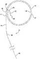
本主題は、とりわけ、遠位針セグメント、中央ループ状又はコイル状左心房セグメント、及び1つ以上の線形の細長い近位セグメントを含む、ガイドワイヤ(GW)を経由してLAへのアクセスを得るため、及び心臓のLAへの構造的又は他のデバイス送達に関するプラットフォームとして機能するための両方で、非常に効率的かつ安全な方法で経中隔穿刺を実現することを対象とする。具体的には、本主題は、経中隔穿刺針12とともに組み込まれた経中隔GW10を部分的に対象とする。GW10は、比較的剛性の近位セグメント端16及び中央ループセグメント14を備えることができ、遠位端22は、経中隔針12との接合部を備える。1つ以上の中央セグメントGWループ24、26は、LA208内に静止することができる。中央ループセグメント14は、形状記憶材料から形成されて、少なくとも2つのループ状セグメント、例えば、第2のより遠位の、通常外側の、広幅コイル24、及び第1のより近位の内側コイル26を形成することができ、中間セグメント14は、最終的に交換のために外部に静止する近位端25において細長い線形剛性GWセグメント16と連続することができる。 The present subject matter gains access to the LA via a guidewire (GW) that includes, among other things, a distal needle segment, a central looped or coiled left atrial segment, and one or more linear elongated proximal segments. It is intended to achieve transseptal puncture in a highly efficient and safe manner, both for the purpose and to serve as a platform for structural or other device delivery to the LA of the heart. Specifically, the present subject matter is directed in part to
本主題は、GW10、経中隔拡張器108、及びシース100を備える、FO202を横断することができる経中隔GW穿刺システムを更に対象とする。GW10の遠位端は、その遠位端22においてループ状GWセグメント14に取り付けられた経中隔針12を備えることができ、順に、直線状の剛性GWセグメント16の遠位端17と連続して位置決めされ得る。経中隔針12は、ループ状GWセグメント14への取り付け点において形状記憶を有することができ、形状記憶は、ループ24、26内及びループ24、26の中心の非外傷性安定性を維持するために、ループ状GWセグメント14に関して予め指定された角度を保持する、経中隔針12を有するのに十分である。ループ24、26のうちの1つ以上は、LA208内に位置決め、かつ安定化することができ、LA208の内側表面に隣接して静止している。中央のループ状セグメント14は、形状記憶材料で形成されて、2つのループ24、26を形成することができ、より近位コイル24の近位端25は、GW16の近位細長剛性セグメントと連続性にあり、二次屈曲部29は、GW10の細長い直線状の近位セグメントに移行するRA206内に位置決めされ得る。 The present subject matter is further directed to a transseptal GW puncture system capable of traversing
経中隔拡張器108は、細長いカテーテル109を備えることができ、これは、シース100内に静止し、狭小拡張器遠位セグメント110まで先細りになり、カテーテル管腔111は、全体にわたってGW10と互換性があるままであり、両端値を含む、0.021~0.035インチ、又はそれ以上の全範囲の直径を有し得る。遠位セグメント106に沿ったいくつかの点では、シース100上の放射線不透過性先端部マーカ123と重なるように位置決めされた放射線不透過性マーカ122であり得、その点で、経中隔拡張器108及びシース100は等価の外径である。拡張器108は、ハンドル104の遠位端に隣接するアクチュエータ112の一連の前方移動によって、FO202を「テンティング」するためにFO202上の正確な位置に前進させることができる。近位シースハンドル104上の操縦可能な操作は、順行及び逆行屈曲作用を可能にすることができ、シース100全体の前方又は後方トルク付与付けは、シースの遠位端124及び特定の処置のために特定のFO部位に隣接する保持された拡張器先端部110を位置決めするために実施され得る。近位シース100上でのアクチュエータ112の使用を伴う、拡張器遠位セグメント110の安定したシース100に対する前進及び後退移動は、拡張器108の近位端119と相互作用することができる。 The
一度FO202が、経中隔針12を収容する拡張器108とともにテンティングされると、針12は、前進し、FO隔壁202を穿刺し、LA208に横断することができる。経中隔針12は、FO202を超えて前進した後に接続されるコイル状GWセグメント14上のヒンジ点20において、別個の角度で形状記憶部から折り畳み又は屈曲することができる。これは、両端値を含む、約45~140度の範囲であり得る、角度を形成することができる。経中隔GW10の更なる前進は、LAチャンバ208内のGW10のループ状区分14コイルを位置決めすることができ、また、ループの中心に残ることにより、中心LA208において針の位置を外傷なく保つことを支援する。好ましくは、GWコイル24、26は、小さい内径コイル26、及びより大きい外径コイル24を有し、針12をLA208の中心に保つことを支援する。直径のより小さい内側コイルは、針12がLA壁内の組織に損傷することを防止することができる。別の実施形態では、コイル24、26は、等しい直径であってもよい。 Once FO 202 is tented with
別の実施形態では、コイル24、26は、図3及び図4に例解されるようにオフセットされて、針12の中心場所を保つことを更に支援することができ、これはまた、第3の寸法で折り畳まれ得、追加的な特徴は、折り畳まれた遠位経中隔針12が前進し、内側に偏向されるとき、LA208構造体を穿刺する余地を小さくし、中心針12の位置をオフセットされているが等間隔のループ14内に維持することを更に支援する。コイル24、26は、両端値を含む、おおよそ0.75~2cmだけオフセットされ得る。コイル24、26は、剛性の中間体であってもよく、LA自由壁とのより少ない外傷性相互作用を可能にする。右心房GWセグメント内の二次屈曲部29は、FO202を超える垂直軌道、及びIVC215における同軸を保つことを支援することができる。細長い近位剛性GWセグメント16は、例えば、260cmの長さを有することができるが、カテーテル又はデバイス交換の目的のために著しく長くなり得る。 In another embodiment, the
本主題のシステムの前方位置決めは、正確なデバイス位置決めのための、遠位シースの正確な位置決めを可能にし、それによって、所与のデバイスのための特定の左心臓標的、すなわち、LAA210、MV212によって最終的に決定される理想的なLA208の位置決めを確立する。システムは、直感的かつ単純であり、エコー又は他の画像化誘導下での反復的な拡張器の前進を使用することによって、特定のFO202標的上に正確に位置決めする。コイルが、FO202を超えて前進し、LA208内に固定された後、拡張器108は、次いで、コイル状GW10の上をLA208へと前進され得、シース100がLA208に横断するまで、重なり合う放射線不透過性セグメントを定位置に保つ。遠位拡張器端106及びシース先端部124上の重なり合う放射線不透過性マーカ122、123は、それらが、FO202を超える拡張器108及びシース100の滑らかな同時前進のために等価直径であることを確認するために使用することができる。 Anterior positioning of the subject system enables precise positioning of the distal sheath for precise device positioning, thereby allowing specific left heart targets for a given device, i.e., LAA 210, MV 212 Establish the final determined ideal LA 208 positioning. The system is intuitive and simple and precisely positions over a
シース100の偏向可能かつ操縦可能な性質により、シース100は、様々な患者固有の解剖学的構造において、様々なRA206サイズ及びFO202角度のための単一サイズの前方向きカテーテルシステムを使用して、方向性、角度付け、及び到達する範囲を取得することを可能に得る。 Due to the deflectable and steerable nature of the
集合システムは、好ましくは、後退した針12を収納する拡張器108をFO202上の正確なテンティング位置へ反復的に前進させるための「汎用的な」カテーテルシステムによって送達される針付きGW10を含む。ハンドル104に隣接するシース100上のアクチュエータ112は、針穿刺の前にFO膜を「テンティング」するために、遠位セグメント110の高度に制御された前進を可能にすることができる。アクチュエータ112は、回転可能なハンドル104から操作者の手を取り外すことなく、操作者の親指で前進又は後退させることができる。拡張器108は、より可撓性の遠位セグメントを有して、LA208内のコイル状GWセグメント上の滑らかな追跡を可能にする。偏向可能なシース先端部124は、単極又は双極性の方向性を有してもよい。偏向可能なシース100は、例えば、FO202に対する垂直度をより容易に確立するために、両端値を含む、2~20度の範囲であり得る、RA 206内に遠位固定された2度屈曲部を有し得る。標準的な市販のシース拡張器カテーテルはまた、前述の新規針GWと組み合わせて使用されてもよい。 The assembly system preferably includes a needled
有利には、本主題は、以下:(1)改善された使いやすさ、(2)正確な遠位制御に関する直感的操作、(3)改善されたデバイス及び処置の有効性、(4)広範囲の操作者のスキルにわたる増加したデバイス安全性、(5)増強されたワークフロー及び減少した処置時間、並びに(6)複合針GWに対する減少した処置コスト、を満たすシステム及びデバイスを提供する。 Advantageously, the present subject matter provides: (1) improved ease of use, (2) intuitive operation for precise distal control, (3) improved efficacy of devices and procedures, (4) wide range of (5) enhanced workflow and reduced procedure time, and (6) reduced procedure cost for compound needle GW.
本主題のこれら及び他の実施例並びに特徴は、少なくとも部分的に、以下の「発明を実施するための形態」に記載される。この概要は、本主題の非限定的な実施例を提供することを意図しており、排他的又は網羅的な説明を提供することを意図するものではない。以下の「発明を実施するための形態」は、本主題に関する更なる情報を提供するために含まれる。 These and other embodiments and features of the present subject matter are described, at least in part, in the Detailed Description below. This summary is intended to provide non-limiting examples of the subject matter and is not intended to provide an exclusive or exhaustive description. The following Detailed Description is included to provide further information on this subject matter.
図面では、いくつかの図を通して、類似の特徴及び構成要素を説明するために、同様の数字が使用され得る。図面は、概して、本特許文献に記載されている様々な実施形態を、制限するものではないが、例として例解する。
図面は、必ずしも縮尺通りではない。特定の特徴及び構成要素は、目盛り又は概略的な形態で誇張されて示されてもよく、いくつかの詳細は、明瞭性及び簡潔性の目的で示されない可能性がある。 Drawings are not necessarily to scale. Certain features and components may be shown exaggerated in scale or schematic form, and some details may not be shown for purposes of clarity and brevity.
図面中のガイド番号を参照すると、本主題の経中隔穿刺システムは、好ましくは、限定されるものではないが、「汎用的な」システムであり、これにより、単一サイズのシステムが、様々な解剖学的構成及び心房サイズにおいて使用され得る。システムは、遠位経隔壁針と、LA206内のGW固定のための隣接するコイル又はループと、を有する交換GWを含む、特殊な構成要素を含む。加えて、システムは、偏向可能なシースによって支援されるFO上の制御された位置決めのために、近位シースハンドル上のアクチュエータと相互作用する拡張器を含んでもよい。 Referring to the guide numbers in the drawings, the subject transseptal puncture system is preferably, but not exclusively, a "universal" system whereby a single size system can be can be used in any anatomical configuration and atrial size. The system includes specialized components including a replacement GW with a distal transseptal needle and adjacent coils or loops for GW fixation within the
ガイドワイヤ10
ここで、経中隔針-GW10を例解する、図1~図4を参照する。経中隔針-GW10は、別個の経中隔針並びに複数のGW交換、様々な解剖学的構造を治療するための長さ、及び湾曲の必要性を回避することができる一体型構成要素であり得る。経中隔針-GW10は、少なくとも3つの画定されたセグメント:(1)遠位の経中隔針12、(2)中央又はループ状のLAセグメント14、及び(3)近位の細長い直線状の剛性セグメント16を有することができる。guide
Reference is now made to FIGS. 1-4, which illustrate a transseptal needle-GW10. Transseptal Needle—GW10 is an integrated component that can avoid the need for a separate transseptal needle as well as multiple GW exchanges, lengths and curvatures to treat various anatomy. could be. Transseptal needle—
針12
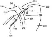
経中隔針12は、GWループセグメント14の遠位端22と連続して位置決めされ得る。経中隔針12は、好ましくは、比較的短く、両端値を含む、約0.75~2.0cmの長さである。針12は、超低輪郭先端部18を有することができる。針12の近位端20は、隣接する遠位ループセグメント14と連続することができ、前進前、拡張器先端部の中心管腔111内に保持されるときに線形であるように構成され得る。
経中隔針12は、抵抗を最小限に抑えるための潤滑性コーティング、及び、密集した傷痕又は動脈瘤であり得るものを含む、FO202(図8に例解される)を超えて穿刺し、容易に移行するための、鋭い先細り先端部18を有することができる。FO膜を超える偶発的な針の揺れ、及び好ましい穿刺部位の損失は、針先端部18上の極微な点、前方向きの先細り経中隔拡張器108の、拡張器先端部18による膜の安定した位置決め及び「テンティング」のためのFO202への低速な反復送達によって回避され得、これは、順に、偏向可能な経中隔シース100によって支持される。この前方向きシステムで、FO202を超える摺動をもたらす意図されていない前方又は後方トルク付与力は、かなり最小限に抑えることができる。 The
経中隔針12は、好ましくは、形状記憶を有するニチノールを含む、ステンレス鋼又は合金などの金属材料で構成することができ、例えば、溶接又は場合によっては相互嵌合スロットで、GWループセグメント14に取り付けることができ、これは、相互作用して、針が針自体を折り畳むことを可能にする、より安定した、なおも可撓性の結合体を形成し、それによってLA自由壁、肺静脈などの穿刺を回避する。針12とループセグメント14との間に予め成形された角度を形成する他の手段もまた考えられ、かつ利用され得る。 The
経中隔針12は、ループ状GWセグメント14の遠位端22に接続する近位端/ヒンジ点20で鋭角を成すことができ、LAループセグメント14の中心に予め指定された角度を保持し、それゆえ中心LAループセグメント14内の非外傷性安定性を維持し、肺静脈、LAフリー壁、及びLAA210を含む、LA208構造の接触及び可能な穿孔を防止する。 The
GW前進及び経中隔穿刺に続いて、針12は、図1~図4に例解されるように、隣接するループ状GWセグメント14とともに、中心で、好ましくは鋭角で急激に屈曲することができる。針12は、LA208に進入した後に直線状のままであるが、遠位ループ状GWセグメント14に対して、好ましくは、両端値を含む、約45~140度の角度で内側に屈曲することができる。経中隔針先端部18の直径は、超低輪郭につぶされ、遠位ループセグメント14を結合するために後に先細りになることができ、両端値を含む、0.021~0.035インチ、又はそれ以上の範囲の輪郭に移行する可能性が最も高い。 Following GW advancement and transseptal puncture, the
ガイドワイヤループセグメント14
ループ状GWセグメント14は、LA208内で非外傷的にGW10の位置を安定化させるように設計することができ、加えて、左心房自由壁を不必要な針穿刺から保護することを支援する。2つ以上のループ状セグメント24、26は、典型的には、直径が約2.5~4.0cmの範囲であってもよく、ループ状セグメントが経中隔拡張器108からLA208に出る際に形状記憶によって形成されてもよい。一実施形態における遠位GWループ状セグメント14は、図3~図4に例解されるように、LAチャンバにおける配備時に再び形成される複数の形状の、2つのほぼ等しいサイズの円形又は非円形ループによって形成され得る。
The looped
コイルは、少なくとも4つの有用な機能を提供する。
1.コイルは、LA208内の拘束されていない既知の形状をとることによって、正しいLAチャンバの位置決めを確認することができる。
2.コイル14は、LA208内の安定した位置決めを維持して、RA206へのGW10の偶発的な引き抜き又はLA自由壁若しくは肺静脈への強力な針先端部12の前進を回避することができる。
3.外側広幅コイル24は、より長いGW支持ランプを提供することができ、その上で、拡張器108及びシース100は、カテーテル支持を容易にするために、曲線の周囲のLA208への抵抗をより小さくして前進させることができる。
4.コイルは、中心に位置決めされた針12が、LA208構造を貫通することを避けて安全な距離に維持される外側保護シールドを形成することができる。Coils serve at least four useful functions.
1. The coil can confirm correct LA chamber positioning by assuming an unconstrained known shape within the
2.
3. The outer
4. The coil can form an outer protective shield that keeps the centrally positioned
別の実施形態では、図1~図4に例解されるように、内側コイル26の直径が外側コイル24の直径よりも小さい、少なくとも2つの円形コイルが存在し、内側コイルは、それゆえ外側コイル24の中心にある。この実施形態では、より大きい、外側コイル24は、内側コイル26の任意の立体構造変化のない状態で、LA208構造によって圧縮され、それゆえ、遠位針12の変形を更に保護し、その中心場所を保つことができる。一例として、GW10の内側コイル26は、約2.5cmなど、両端値を含む、約1.5~3.0cmの直径を有し得る。外側コイル24は、約3.5cmなど、両端値を含む、約3.0~4.0cmの直径を有することができる。 In another embodiment, as illustrated in FIGS. 1-4, there are at least two circular coils, the diameter of the
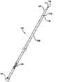
第3の実施形態では、2つのコイル24、26は、平行部分24a及び26aを有し、直径が同等ではなく、両端値を含む、約0.75~2.0cmだけオフセットされ得る。更に、図5に例解されるように、2つのオフセットワイヤコイル24、26の中心の第3の寸法における遠位経中隔針12及びGWループセグメント14の接合部での第2の事前形成された屈曲部が、組み込まれ得る。その目的は、針12が、この実施形態の屈曲時に二次元で円周方向に中心を合わせられるだけでなく、針12が、2つのオフセットループ24、26の幅の間の第3の寸法で中心に方向付けられ得ることを可能にすることによって、LA208の針穿孔を防止することを更に支援することである。点線25によって例解されるように、コイル24、26の平行部分24aと26aとの間の距離は、例えば、約1cmであり得、約0.75~2.0cmの範囲であってもよい。 In a third embodiment, the two
近位ガイドワイヤセグメント16
近位GWセグメント16は、セグメント16の遠位端17において隣接するコイルセグメント14と連続することができる。近位GWセグメント16は、近位自由端28を含むことができ、LA内に位置決めされた遠位GWループセグメント14を保ちながら、カテーテル又はデバイス交換を可能にするための適切な長さを外面化する。近位GWセグメントの遠位端17は、心房中隔を超えてLA208へと直線的に移行することができる。次いで、ほぼ中間RA206において、浅い固定された第2度の屈曲部29が存在し得、両端値を含む、2°~20°の好ましい角度を保持する。細長い近位剛性GWセグメント16は、長い近位セグメント17の最も遠位端から、最も近位端28まで延在し、両端値を含む、0.021~0.035インチの好ましい直径を有する。長い近位剛性GWセグメント16は、長さにおいて、両端値を含む、240~300cm、好ましくは260cmで延在し得る。この長い剛性GWセグメント16は、左心臓標的に送達するためのカテーテル及びデバイスのアレイを交換するための支持レールとして機能することができる。
A
シース100
図5を参照すると、経中隔送達シース100は、単極又は双極、例えば、上方/下方屈曲のために回転可能な近位人間工学的ハンドル104で作動される偏向可能なシース、並びに最適な前方/後方位置決めのための1対1のシーストルク制御であり得る。経中隔シース100の前進又は後退は、全ての平面における制御された非外傷性誘導のための上方及び下方の位置決めを可能にすることができる。シース100は、アクチュエータ112及び遠位セグメント107に隣接して位置付けられた近位端102を有することができる。商業的利用のために設計された現在の経中隔システムは、概して、過度に積極的であり得る(長さが過剰である)大腿静脈アクセス照準からのシース/拡張器システムの時計回りのトルクを使用して、FO202に至り、これは、オーバーリーチの拡張器108が、心房中隔の高くなった隆起部上で遠位に一瞬「引っ掛かる」場合、偶発的に「蓄積された」トルクをもたらす可能性がある。拡張器遠位セグメント110をFO202内に位置決めするための更なる取り組みは、RA206自由壁又は付属物の穿孔をもたらし得る。逆に、不十分な長さ又は「リーチ」の拡張器108、及びFO202を超える膜の係合不能は、FO202の穿刺不能をもたらす。
Referring to FIG. 5, the
シース100は、矢印125によって例解される、上方及び下方遠位シース屈曲のための人間工学的な双方向回転可能ハンドル104、及びシース100の先端部124におけるリーチを有することができる。加えて、前方から後方への位置で遠位に伝達される1:1トルクは、シース100のワイヤ編組補強(図示せず)を通して達成することができ、これはまた、デバイスの送達を増強させるためのバックアップ支持も改善することができる。シース100は、最初に、蛍光透視及びTEE誘導を使用して、及び利用可能な場合、場合によってはリアルタイムMRI及びコンピュータ断層撮影を使用して、心房中隔に隣接するが、心房中隔に係合せず位置決めされ得る。 The
シース100が、撮像誘導下で、RA206内のFO202からの適切な短い距離(例えば、約0.5~2.0cm)で、正確に位置決めされると、拡張器108は、シース100を静止状態に維持しながら前進させることができる。拡張器のためのシースハンドル104及び隣接するアクチュエータ112は、操作者の対側手の使用を必要とせずに、一方の手が適所に維持された状態で、システム(シース及び拡張器)の操作を可能にすることができる。拡張器108のためのアクチュエータ112は、拡張器108上の摩擦要素121と相互作用することによって、反復前方前進又は後退のために、操作者の親指又は他の指によって操作され得る。ワイヤ編組強化シース100は、拡張器108の遠位セグメント110を前進させ、続いて拡張器108を、膜の「テンティング」のために、FO202の正確に制御された特定の場所に前進させるための、強力なバックアップ、ねじれ耐性支持を提供することができる。 Once the
シース100は、好ましくは、高度に可変のデバイス輪郭を収容するための、拡張可能なシャフトを含むが、必要とはせず、一方で、一連の固定直径のシースが、様々なデバイス輪郭を収容するために使用されてもよい。約8.5Fr~潜在的に最大30Frの範囲の、理想的に拡大可能な、又は拡張可能なシースは、異なる処置のために利用可能な複数のシース直径を維持する必要性を排除することができる。それゆえ、一実施形態は、直径の範囲を超えて拡張可能であるように適合される単一のシースサイズである。近位ハンドルからの2つ以上の距離での剥離性を必要とし得る経中隔シースは、複雑な曲線又は複数の曲線の周囲のデバイスの送達に好ましい場合がある。
複数の他の支持構造体は、シース本体内で直線的に延びて、より角度をつけた解剖学的構造を超える後続のデバイス送達のための適切なレベルの支持を保つことができる。2~20度の二次屈曲部は、例えば、より遠位の偏向可能な屈曲部の近位に位置決めされてもよく、これは、強い同軸バックアップ支持のためにFOにおいてより垂直な角度を実現することを支援し得る。加えて、これは、180度を超える遠位屈曲を可能にすることができ、これは、左心臓の内側面内で適切なシース位置決めを実現するために適時必要とされ得る。シースハブ114上の緊密な止血弁は、例えば、0.021インチまでの直径を有するものを含む、GW10の周囲の後方出血を最小限に抑えることができる。好ましくは、シース100は、長さ90cm(使用可能長さ70cm)以上である。拡張器をシースに係止するためのハブが、組み込まれてもよい。 Multiple other support structures can extend linearly within the sheath body to maintain an adequate level of support for subsequent device delivery over more angled anatomy. A 2-20 degree secondary bend, for example, may be positioned proximal to the more distal deflectable bend, which provides a more vertical angle in the FO for strong coaxial backup support. can help you do that. Additionally, it can allow greater than 180 degrees of distal flexion, which may occasionally be required to achieve proper sheath positioning within the medial aspect of the left heart. A tight hemostasis valve on the
拡張器108
経中隔拡張器108は、内部シース直径と互換性があり、拡張器108の遠位端における固定外径118に、106で例解される後方へ逆先細りを有する超低輪郭遠位セグメント110を有することができる。拡張器108は、FO膜の「テンティング」が、実施されている処置に特有のTEE又は他のリアルタイム撮像検出器によって可視化された位置に特有の正確な位置において実証されるまで、前方運動で前進させることができる。
The
好ましい実施形態では、拡張器108は、摩擦接触要素121によって、又は拡張器運動の正確な穏やかな制御のためのインターロックギアの使用によって、シースハンドル104に隣接するアクチュエータ112と相互作用することができる。拡張器の前進又は後退を可能にするアクチュエータ112は、好ましくは、同側の親指で制御され、拡張器108及びシースハンドル104の両方を片手で操作する能力を保つ。拡張器108は、その長さに沿った可変の可撓性を有することができ、より可撓性の遠位セグメント118が、GWループ状セグメント14の上を前進する際にカテーテルシステムの過度な整流、又は移動を防止する状態である。 In a preferred embodiment, the
拡張器遠位セグメント106は、静止遠位シース100を越えて、好ましくは最大約5cmまで前進することができるはずであるが、例えば、シース先端部を越えて、両端値を含む、約3.0~8.0cmまで延在するように変更されてもよい。これにより、遠位GW10の上で、FO202を超え、かつLA208への拡張器108の制御された前進を可能にする。RA206内に固定されたシース104を維持しながら、LA208への拡張器108の中隔穿刺及び前進の後、放射線不透過性マーカ122、123が隔膜のRA206側に重なるまで十分な空間が存在するべきであり、その後、面一の外径を有する、経中隔拡張器108及びシース100を有する複合システムは、ここで、単一ユニットとしてLA208内に前進させることができる。拡張器遠位セグメント106は、低輪郭先端部110で終わり、拡張器遠位セグメント106の近位に放射線不透過性マーカ122を有してもよく、シース先端部124上の放射線不透過性マーカ123の輪郭に一致し、FO202を超える同時前進のための2つ間の滑らかな移行の点となり、心房中隔横断点上のシース先端部縁部の「ハングアップ」を防止する。 The dilator
使用方法
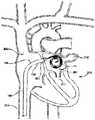
図7及び図8を参照すると、例示的な操作方法が、ヒト患者201上で以下の通り成され得る。以下に記載されるように、この技術は、概して、標準的な蛍光透視法が追加されたTEE又はTTEによって案内される。処置はまた、心臓内エコー、リアルタイムMRI、又は前処置体積レンダリングコンピュータ断層撮影画像との画像統合によって案内され得ることを理解されたい。この後者の撮像方法は、予め取得されたコンピュータトモグラフィー画像が案内のために配向及び重ね合わせられ得る、標準的な蛍光透視画像を使用する。心臓200及び経中隔シース100の心房領域への挿入を含む、ヒトの解剖学的構造の一般的な説明のために本明細書に組み込まれる、Nanceらの米国特許第8,900,214号を参照する。Method of Use Referring to FIGS. 7 and 8, an exemplary method of operation can be accomplished on a
0.032インチの先端部J字のGWは、蛍光透視法を使用して、右大腿静脈216から上大静脈218に前進される。偏向可能なシース100及び拡張器108は、先端部J字のGW10の上のユニットとして前進し、RA206の中央において位置決めされる。先端部J字のGW10が取り外され、拡張器108がフラッシュされる。GW10の遠位先端部18は、次いで、蛍光透視下で0.032インチの互換性拡張器108に前進され、GW10の遠位先端部18は、拡張器遠位セグメント110のすぐ近位に位置決めされる。 A 0.032 inch J-tipped GW is advanced from the right
シース100上の人間工学的ハンドル104は、軸方向に配向されて、偏向可能な先端部124がFO202に向かって前屈曲されることを可能にする。シース100をFO202に向かって操作する前に、拡張器108の1~3cmを、固定シース100の遠位に、蛍光透視及び心エコーで前進させる。この前方又は後方の配向を達成するために、シース100は、前方に、又は後方にトルクをかけられる。シース100は、より上方位置又は下方位置を得るために前進又は引き抜かれる。再び、近位シースハンドル104は、遠位先端部124を上方、すなわち逆行、又は下方、すなわち、順行、軌道に屈曲させるために曲げられる。TEEプローブは、直交図:上方-下方配向のバイカバル図及び前方-後方位置決めを実証するための大動脈レベルでの短軸図を使用する、FO202及び隣接する拡張器遠位先端部110の最適な撮像のために最も一般的に使用される。これらのTEE図を使用して、処置特有の穿刺のためのFO202上の正確な位置が、取得され得る。シースハンドル104に隣接するアクチュエータ112は、拡張器先端部110をゆっくりと反復的に前進させて、FO202内に「テンティング」及びTEEによって確認された正しい位置を作成するために使用される。拡張器遠位先端部110が誤って位置決めされる場合、拡張器108は、アクチュエータ112で引き抜かれ、シース100を操作した後に再方向付けされ得る。
テンティング位置を使用して確認された正確な位置決めにより、GW10の近位端は、前進し、針先端部18が、穿刺し、FO202膜を横断する。GW10が更に前進する際、針12は、GW10のループセグメント14に取り付けられるヒンジ点20において急激に屈曲する。GW10が更に前進する際、その遠位コイル14は、LA208内に自己位置決めされ、針12は、コイル24、26の中心に屈曲した状態に保たれる。カテーテルは、常に吸引され、交換でフラッシュされる。患者は、GWループセグメント14がLAに前進するとすぐに、治療的にヘパリン化される。GW10の正確な位置決めは、その事前形成された形状を検証することによって確認される。コイル状又はループ状セグメント14は、本明細書に記載されるように、いくつかの異なる実施形態をとることができる。拡張器108は、シース100をRA206内の固定位置に維持するコイル状ワイヤの上を前進させる。 With correct positioning confirmed using the tenting position, the proximal end of
適切な長さの拡張器108が蛍光透視下で前進した状態で、拡張器108及びシース先端部124上の放射線不透過性マーカ122、123は、RA206内で重ね合わさり、両方のカテーテルの外径が等価であり、単一ユニットとしてLA208に前進する準備ができていることを確認する。ここで、シース先端部124は、FO202を超えて、かつLA208内に静止する。再び、全ての拡張器108及びシース100の操作は、片手処置として実施される。拡張器108は、取り外され、GWワイヤループ24、26及びシース100をLA208内に静止状態に維持する。 With the appropriate length of
GW10の細長い近位セグメントは、ここでシース先端部124に前進された一次デバイスが装填され、GW10は、取り外される。次いで、シース100は、より微細に操作されて、デバイスを標的に送達し、続いて配備され得る。配備後、偏向可能なシース100は、RA206に引き戻され、続いて患者から取り出される。ヘパリンは、プロタミンと入れ替えられ、経皮血管入口は閉鎖される。 The elongated proximal segment of
この経中隔処置は、穿刺される前に、FO202の正確な位置に反復的に前進される、前向きカテーテルシステムを用いて実施される。カテーテルシステムの性質は、1つのデバイス形状のみがLA208にアクセスするために必要となるようなものである。これは、カテーテルが、多数のカテーテルサイズを使用して、FO202にトルクをかけ、初期に小さすぎて、FO202に到達できない、又は長すぎて、FO膜から滑り落ちるリスク、及び潜在的にRA自由壁を穿孔するリスクを患者に負わせる場合がある、現在の技術とは異なる。 This transseptal procedure is performed using an anterior catheter system that is repeatedly advanced to the correct location of the
ガイドワイヤ、針。拡張器及びシース
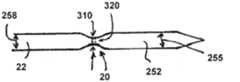
図9A及び図9Bは、先に図1~図4に前述されたように、本主題の経中隔ガイドワイヤ10のガイドワイヤループ14の遠位端であり得る、ガイドワイヤ遠位端22に関する実施形態を示す。経中隔ガイドワイヤ10は、本主題の拡張器シャフト109の拡張器遠位セグメント106内に位置決めされ得る。拡張器シャフト109及び拡張器遠位セグメント106は、ガイドワイヤ針先端部18、ガイドワイヤループセグメント14、及び経中隔針12が著しい摩擦力なく内部を容易に通過することを可能にする、拡張器管腔直径250を伴う、拡張器管腔111を有する。図9A及び図9Bに示されるように、ガイドワイヤ直径258と同じ直径であることが示される、針本体直径255を有する針本体252は、拡張器管腔直径250よりも約0.002インチ、例えば、(両端値を含む、0.001~0.004インチの範囲)小さくなり得る。針本体直径255は、拡張器管腔直径250よりも著しく小さいということはなく、その結果、拡張器内側湾曲壁260及び拡張器外側湾曲壁265は、針本体252と接触し、針本体中心軸270と拡張器中心軸275との位置合わせを提供することができる。針12は、拡張器中心軸275と同軸である針本体252の軸方向の位置合わせを提供するために、約5mm(両端値を含む、3~20mmの範囲)の針の長さを有することができる。guide wire, needle. Dilator and Sheath FIGS. 9A and 9B illustrate a guidewire distal tip, which can be the distal end of the
針先端部18は、図14Aに示されるように、針本体252から円錐状又は先細りの形状で延在して、心房中隔204のFO202内に見出される組織を貫通することができるか、又は、FO周辺の他の場所を貫通するか、他の血管壁若しくは臓器隔膜を貫通するために使用することができる、鋭い針点285を形成することができる。針点285の拡張器外側湾曲壁265との貫入接触を行うことなく、針-ガイドワイヤ10が、拡張器管腔111内で遠位方向に横断することを可能にするために、針先端部18は、特定の針先端部長295及び針先端部角度300で形成され得る。図9Bに示されるように、拡張器108は、拡張器の曲率半径305で湾曲形状に屈曲させることができる。下大静脈215(図8を参照)からFO202にアクセスするのに必要な拡張器曲率半径305の下限は、約1cm(両端値を含む、0.75~2cmの範囲)であり得る。拡張器管腔直径250は、約0.035インチ、例えば(両端値を含む、0.026~0.038インチの範囲)であり得、針本体直径255は、約0.030インチ、例えば(両端値を含む、0.025~0.031インチの範囲)であり得る。例えば、1cmの屈曲の拡張器曲率半径305の周囲に延在する拡張器108に関する標準的な幾何学的考慮事項を使用すると、針先端部長295がおおよそ2mmであり、針先端部角度が26度、例えば、(両端値を含む、8~30度の範囲)を有する針先端部18は、針点285が拡張器外側湾曲壁265に突き刺さるか、又は貫通することを可能にすることなく、拡張器曲率半径305の周囲で針先端部18の移動を提供することが示され得る。様々な針先端部18の形状(非線形の表面屈曲など)及び角度が、針先端部長295及び針先端部角度300を変更するために、使用することができる。例えば、拡張器管腔直径250よりも小さい、約0.002インチの針本体直径255間の精密許容度は、針本体252と針先端部18との軸方向位置合わせを提供し、その結果、ヒンジ点20における針12の座屈は、著しくなく、経中隔拡張器108は、針12を拡張器中心軸275との同軸位置合わせに方向付ける。 The
図10A~図10Dは、ガイドワイヤ遠位端22と針本体252との間に位置付けられたヒンジ点20の実施形態を示す。ヒンジ点20又はヒンジ20は、例えば、ステンレス鋼、ニチノール、又は他の弾性金属などの弾性材料から形成され得、この弾性材料は、例えば、90度の屈曲部、又は好ましくはより鋭角の屈曲部などの特定の平衡形状を有する。ヒンジ点20が、例えば、拡張器108によって提供されるような拘束力に起因して、一時的に直線形状に真っ直ぐに伸ばされる場合、ヒンジ20は、拘束力を除去するとその屈曲形状に戻る。ヒンジ点20又はヒンジ20は、針本体252に接合されるガイドワイヤ遠位端22の連続部分として形成され得、ヒンジ20は、ガイドワイヤ遠位端22に接合された、針本体252の連続部分であってもよく、又はヒンジ20は、針本体252の両方に接合され、ガイドワイヤ遠位端22に接合される別個の領域であってもよい。ヒンジ20は、例えば、ニチノール針と隣接するニチノールから形成され得、針12は、ガイドワイヤ遠位端22に接合されるか、又は取り付けられ得る。接合プロセスは、様々な溶接、ろう付け、若しくははんだ付け方法を含むことができるか、又は接着剤若しくは機械的接合方法を使用することができる。代替的に、熱加工方法を使用して、ヒンジ点20を、例えば、鋭角などの特定の急角度を有する平衡形状に形成することができる。 10A-10D show an embodiment of
ヒンジ点20は、断面が円筒形であり、図10Aに示されるような、ガイドワイヤ直径258又は針本体直径255の直径と等しいヒンジ直径310を有する、ヒンジ20から形成され得る。ヒンジ20は、例えば、ニチノール又はエルギロイなどの弾性材料から形成され得、その結果、拡張器管腔111内に収容されている間、略線形状を維持するが、拡張器遠位先端部110又は拡張器遠位端110からヒンジ20を送達すると屈曲し、例えば、図10Bに示されるように、ガイドワイヤ遠位端22と針本体252との間の鋭角針-GW角度315又は屈曲(両端値を含む、45~140度の範囲)を有する、平衡形状を形成する。
代替的な実施形態では、ヒンジ点20は、図10Cに示されるように、ガイドワイヤ直径258又は針本体直径255よりも小さいヒンジ直径310を有する円形ヒンジ断面320で形成され得る。より小さいヒンジ直径310は、ヒンジ20が、例えば、略線形の構成で拡張器管腔111内を移動する際、ニチノール材料の弾性変形を介して屈曲することを可能にする。拡張器遠位先端部110からヒンジ20を解放すると、針本体252は、ガイドワイヤ遠位端22で特定の針-GW角度315(両端値を含む、45~140度の範囲)を形成する。 In an alternative embodiment, hinge
更に別の実施形態では、ヒンジ点20は、図10D及び図10Eに示されるように、ヒンジ断面320を矩形ヒンジ322の状態で形成され得る。ヒンジ20は、弾性材料から再び形成することができるが、機械加工されるか、又は別の方法で矩形形状に形成され、円形の形状にわたる利益を提供することができる。針本体252は、(例えば、概して紙の平面におけるループセグメント14として示されるように)ガイドワイヤループセグメント14の平面によって画定される特定の方向において屈曲されることを意図されるため、ヒンジ20は、ヒンジ屈曲軸323がループセグメント14と同一平面上にあるように形成され得る。ヒンジ高さ325は、ヒンジ幅330よりもはるかに小さくなり得、それにより、ヒンジ20をヒンジの弾性限界よりもはるかに下回って維持しながら、ヒンジ20の屈曲を容易にすることを可能とし、その結果、屈曲は、拡張器管腔111内に制限されながら、完全に弾性のままである。ヒンジ幅330は、ガイドワイヤ遠位端22においてガイドワイヤ直径258と等しくなり得、ガイドワイヤ遠位端22の曲率と類似の曲率である、丸みを帯びた縁部を有することができ、ヒンジ高さ325よりも大きいヒンジ幅330は、針本体252に伝達されるガイドワイヤ10の最適な押込みを提供することができ、その結果、針先端部18は、図14Aに示されるように、FO202を超えて押され得る。ヒンジ長さ335は、ヒンジ20が、拡張器108内で略線形の構成の間に、弾性状態のままであることを確実にするように調節することができ、その結果、拡張器遠位先端部110からのヒンジ20の解放時に、ヒンジ20は、例えば、(45~140度の範囲の)鋭角針ガイドワイヤ角度315に屈曲し、図10Eに示されるように、針本体252をガイドワイヤ遠位端22に対して鋭角に屈曲する。 In yet another embodiment, the
より長いヒンジ長335は、より長い長さにわたって屈曲変形を拡げ、したがって、ヒンジ点20は、拡張器108内で真っ直ぐな形状で送達された後に、平衡屈曲形状に戻るために、より大きな弾性を保持する。ガイドワイヤ直径258よりも小さくなり得るヒンジ高さ325は、ヒンジ点20の屈曲中に、ヒンジ点20を弾性状態に更に維持する。ヒンジ幅330とともにヒンジ高さ325は、経中隔拡張器108を出る時に、ガイドワイヤ遠位端22に関して鋭角に針を折り畳むために提供される力の量を判定する。ヒンジ20は、それによって、例えば、ガイドワイヤ直径258に対してより小さいヒンジ高さ325で設計されて、ガイドワイヤ直径258と同じ直径を有するヒンジ20を伴う円筒ワイヤからヒンジ20を形成するよりも、針本体252を折り畳むためのより小さい屈曲力を提供することができる。 A
更に別の実施形態では、図11A~図11Cに示されるように、先端部シース340が、針先端部18の周囲に配置されて、針本体中心軸270と拡張器中心軸275との同一直線上の位置合わせを提供する。図11Aに示されるように、先端部シース340は、針先端部18の周囲に配置され、針点285までわずかに遠位に延在する。先端部シース340は、針本体252の周囲に摩擦嵌合を介して嵌合して、経中隔ガイドワイヤ10及び針が、座屈なく、かつ針点285が拡張器管腔壁342に穿刺することなく、拡張器管腔111内で遠位方向に横断することを可能にし得る。先端部シース340は、例えば、拡張器管腔直径250から、(先端部シース直径は、拡張器管腔直径250よりも0.002~0.005インチ小さい).003インチの適切なクリアランスを提供して、先端部シース340及び針本体252がともに、拡張器管腔111内を遠位に前進する際に容易な移動を可能にする、先端部外径345を有するように形成される。拡張器遠位先端部110に位置付けられるのは、拡張器管腔111の内側から拡張器108の外側の領域への先端部シース340の移動を防止する、拡張器停止部350であり得る。拡張器停止部直径355は、例えば、先端部シース外径345未満の0.004インチ(両端値を含む、0.002~0.008インチの範囲)であり、先端部シース340が、拡張器停止部350を超えて拡張器管腔111から出ることを防止することができる。針本体252及び先端部シース340が拡張器管腔111を通って遠位方向に前進する際、先端部シース340は、拡張器停止部350と接触し、拡張器停止部350と接触したままであり、一方、例えば、拡張器停止部直径355よりも0.002インチ小さくなり得る、(両端値を含む、0.001~0.005インチ小さい範囲)針本体252は、拡張器停止部350を自由に通過することができる。先端部シース340は、針先端部18が拡張器管腔壁342内に穿刺することを防止する、保護被覆を針先端部18に提供することができ、また拡張器中心軸275と同一直線上位置合わせの状態の針本体中心軸270を提供することもできる。 In yet another embodiment, as shown in FIGS. 11A-11C, a
先端部シース340は、例えば、テフロンなどの潤滑性プラスチック材料から形成することができ、その結果、拡張器108を通って横断する間、拡張器管腔壁342に対して十分に摺動することができる。また、テフロン表面は、先端部シース340が拡張器停止部350と接触した後に、針本体252及び経中隔ガイドワイヤ10が、先端部シース340の内側表面を通過することを可能にする。先端部シース内径360は、例えば、ガイドワイヤ直径258よりも0.002インチ小さくなり得、拡張器停止部350を通るガイドワイヤ10の無制限の移動を提供することができる。 The
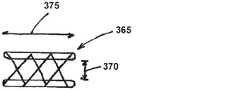
更に別の実施形態では、図11Aに記載されるような先端部シース340は、図11B及び図11Cに示されるように、解放可能な先端部シース365が、拡張器停止部350と接触した後、針本体252からの解放を提供するように形成された解放可能な先端部シース365となり得る。解放可能な先端部シース365は、針本体直径255よりも、例えば、約0.002インチ小さい、(0.001~0.010インチ小さい範囲)先端部シース平衡内径370を有するように形成され得る。より小さい先端部シース平衡内径370は、拡張器管腔111を通る針本体252の遠位側横断中に、解放可能な先端部シース365の針本体252への解放可能な保持取り付けを提供することができる。解放可能な先端部シース365は、例えば、編組管状構造体を用いて、又は、より短い先端部シース長さ375に押し込まれる際に直径が大きくなる傾向があるエラストマーポリマー管状構造体を用いて、形成され得る。図11Cに示されるように、解放可能な先端部シース365が拡張器停止部350と接触すると、解放可能な先端部シース365は、拡張器停止部350との接触時に圧縮され、針本体直径255よりも大きい解放可能な先端部シース拡大直径を有する、解放可能な先端部シース拡大直径380まで、直径が大きくなる傾向があり、解放可能な先端部シース365の拡張により、針本体252及びガイドワイヤ10が解放可能な先端部シース管腔385を自由に通過し、拡張器先端部から出ることを可能にする。 In yet another embodiment,
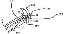
本主題の経中隔ガイドワイヤ10(針-ガイドワイヤ又はガイドワイヤ)、拡張器108、及び偏向可能なシース100は、図12、図13、及び図14A~図14Fに示される構造及び構成を備えることができ、本主題は、例えば、診断又は治療処置を実施するために、RAから左心房室にFOを横断させるために使用され得る。本主題はまた、血管導管の壁を横断し、心臓の別の隔膜を横断するか、又は身体の別の臓器の壁/隔膜を横断するために使用され得ることが理解される。ガイドワイヤ近位セグメント16、ガイドワイヤループセグメント14、及びガイドワイヤ遠位端22は、図12に示され、図1~図4及び図7~図8に前述される。主題は、本主題の針-ガイドワイヤ10が、心房中隔204に偶発的に衝突又は侵入することからの経中隔針の急激な屈曲を可能にすることなく、かつLAにおけるガイドワイヤループセグメント14の適切な形成を防止することなく、FO壁390を超えて、安全かつ効率的な通路を提供することを意図する。図12、図13、及び図14A~図14Fに示されるように、経中隔ガイドワイヤ10は、針本体252が、急激に屈曲することを可能にし、例えば、ガイドワイヤ遠位端22との鋭角(両端値を含む、45~140度の範囲)などの、針-ガイドワイヤ角度315を形成するヒンジ点20を有することができる。針本体252が拡張器108から出て、LA208へと延在する際(図14A~図14Fを参照)、針先端部18が、心房中隔204に衝突又は貫通せず、それによって、前述されたように、ループセグメント14がLA208に適切に送達されることを防止することが重要である。針先端部18を、心房中隔204を超えて送達するとき、針先端部18の場所を識別することを助けるために、遠位ガイドワイヤ放射線不透過性マーカ395は、針先端部18に隣接した場所で針本体252上に位置付けられ得る。ガイドワイヤヒンジ放射線不透過性マーカ398は、ヒンジ20に隣接するガイドワイヤ遠位端22上に位置付けられて、拡張器遠位放射線不透過性マーカ505の蛍光透視可視化を介して識別される際、拡張器遠位先端部に対する針本体位置の蛍光透視可視化を提供し得る。外部マーカは、患者の身体の外側の場所において、ガイドワイヤ近位セグメント16及び拡張器シャフト109上に代替的に、又は追加的に配置され得、かかる外部マーカは、FOのテンティング中、並びに針-ガイドワイヤ10及び拡張器108がFOを超えて前進する間に、拡張器遠位端110に対するガイドワイヤ針先端部18の軸方向位置決めを判定するために使用され得ることに留意されたい。 The transseptal guidewire 10 (needle-guidewire or guidewire),
図12に示されるように、経中隔ガイドワイヤ10は、ステンレス鋼、ニチノール、又は医療デバイス業界において使用される標準的なガイドワイヤを形成するために、一般的に使用される他の材料などの金属から形成することができる。針の長さ280は、例えば、約5mm(両端値を含む、3~15mmの範囲)であり得、図14B及び後で本明細書において更に記載されるように、適切な針の長さ280を有して、FO202の2~3mmの厚さの壁390を通って横断し、依然として拡張器突出部400内に延在する経中隔針の少なくとも1~2mmの軸方向長さを有して、(図13及び図14Aを参照)ヒンジ点20において屈曲することなく、拡張器突出部400との軸方向位置合わせで針を保持することが意図される。より短い針の長さ280(依然として針の長さ範囲内にある)は、FO壁390を横断するために針の複数の短い前進(例えば、1~3mmの軸方向移動の2~3の前進)を必要とし、続いて針の軸方向位置合わせ支持を提供する拡張器突出部400の複数の同様の前進が続く。より長い針の長さ280(依然として針の長さ範囲内にある)は、針が心房中隔204に貫通しなかったことを確実にするために、より長い拡張器突出部の長さ415を必要とし(図13及び図14A~図14Dを参照)、拡張器遠位端110から針が出て、ヒンジ点20において針-ガイドワイヤ10の屈曲が続き、かかるより長い針の長さ280はまた、拡張器遠位先端部110又は拡張器遠位端110からの針先端部18の配備中に、針先端部18がLA横方向壁405(図14Cを参照)への衝突をもたらし得る。本主題で使用される針の長さ280及び拡張器突出部の長さ415は、全ての針-ガイドワイヤ10をLAに送達する前に、針12をLAの中心領域に送達することを意図している。 As shown in FIG. 12, the
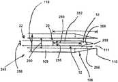
本主題の実施形態の拡張器遠位領域245は、図13及び図14Aに示されるように、拡張器傾斜セグメント410及び拡張器突出部400を備える、拡張器遠位セグメント106を有することができる。拡張器突出部400の外側円筒表面は、拡張器変曲点412において傾斜セグメント410の外側表面に接触する。拡張器突出部400は、傾斜セグメント410から拡張器遠位先端部110まで延在し、低輪郭の薄肉拡張器突出部400に起因して、FO202FOを著しく拡張することなく、FO壁390を通って容易に延在される薄肉円筒形状を有する。拡張器突出部400は、それによって、針が急激に屈曲する、及び潜在的に心房中隔204に衝突するか、又は貫通することを可能にすることなく、経中隔ガイドワイヤ10の針を、FOを通じて、LA208のチャンバに方向付けることができる。拡張器突出部の長さ415は、例えば、9mm(5~18mmの範囲)であり得、より短い拡張器突出部の長さ415は、FO壁390を超えて、LA208に針を方向付けなくてもよく、それにより、針のヒンジ点20が鋭角に屈曲され、潜在的に心房中隔204に衝突するか、又は貫入することを可能にする。より長い拡張器突出部の長さ415は、針をFOの平面に対して垂直に方向付けるための支持を提供しなくてもよく、加えて、かかるより長い突出部の長さ415は、所望よりもLA208に更に延在し得、それによってLA208に送達されるように針先端部18を潜在的に方向付け、LA208の側壁405に衝突させる(図4Cを参照)。 The dilator
拡張器突出部400は、ステンレス鋼、ニチノール、若しくは他の金属で作製された薄肉ハイポチューブから形成されるか、又は、ポリイミド、ポリエチレンテレフタレート、若しくは引張強度が高い他のポリマーなどのポリマー材料から形成され得、拡張器管腔直径250が、0.035インチ(両端値を含む、0.025~0.038インチの範囲)の経中隔ガイドワイヤ10又は標準的なガイドワイヤのための精密許容度(例えば、両端値を含む、0.002~0.004インチのクリアランス)を有する通路を提供することができる状態で、薄肉(例えば、0.003インチの壁厚、両端値を含む、0.0015~0.005インチの範囲)チューブに形成され得る。それゆえ、拡張器突出部400は、ガイドワイヤ固定直径258と同様の外径を有して、FO202を超える容易な移行アクセスを拡張器突出部400に提供する。拡張器突出部400は、拡張器傾斜セグメント410内に延在することができ、かつ接着剤、拡張器108のポリマー材料にインサート成形、熱結合、溶媒結合、又は他の接着方法を介して、拡張器傾斜セグメント410に恒久的に取り付けられ得る。拡張器傾斜セグメント410は、図13に示されるように、拡張器突出部400を形成する薄肉チューブの突出部支持領域420に対する支持及び安定した土台を提供する。拡張器傾斜セグメント410は、拡張器突出部400の直径に等しい小径から、拡張器固定直径118に等しいより大きい直径を有する拡張器肩部425まで、先細りの様式で、拡張器突出部400から近位に延在し、これが前述されたように、偏向可能なシース100(シース直径は、約8.5Fr、例えば、6Fr~20Fr超の範囲)内の最小の摩擦、かつ偏向可能なシース100からの完全な側部支持の状態で通過することができる。拡張器傾斜セグメント410は、潤滑性拡張器傾斜セグメント410の機能的態様、及び圧潰なくガイドワイヤ上で前進させることができる薄肉高圧縮強度の拡張器突出部400に好適な材料で拡張器のこれらの部分を形成することによって、拡張器突出部400と同じ材料で、かつ拡張器突出部400と連続的に形成され得る。
拡張器108は、拡張器肩部425から5mmの軸方向距離で(拡張器肩部の近位の全拡張器シャフト109まで3mmの範囲)、近位方向に延在する拡張器固定直径118を有する、円筒形状の拡張器位置合わせゾーン430を有することができる。拡張器位置合わせゾーン430は、図14Aに示されるように、拡張器中心軸275のシース直線領域440内のシース中心軸435との軸方向位置合わせを提供する。拡張器軸方向位置合わせゾーン430の目的は、拡張器位置合わせゾーン430及び拡張器突出部400に制御された方向性を提供することであり、その結果、拡張器位置合わせゾーン430及び拡張器突出部400は、テンティング525の間、及びFO202を針-ガイドワイヤ10で貫通する前に、偏向可能なシース100を介して、FOに対して垂直であるように方向付けられる。軸方向位置合わせゾーン430は、FOの表面に沿って摺動することなく、FO202内の所望の標的部位を保持するための針の能力を増強させ、角度の付いた隔壁穿刺をもたらす。 The
本主題の経中隔拡張器108は、拡張器位置合わせゾーン430の近位に位置付けられ、シース屈曲領域530の軸方向長さ全体にわたって延在するために、約20mm(両端値を含む、5~50mmの範囲)延在する、拡張器腰部445を有することができる(図14Aを参照)。拡張器腰部445は、拡張器肩部425に近接する拡張器シャフト109の残部よりも可撓性であるが、依然として適切な押し込み性又は拡張器シャフト109の圧縮特性を有する、拡張器シャフト109の領域を提供する。拡張器腰部445は、例えば、拡張器固定直径118の直径の50パーセント(両端値を含む、30~95パーセントの範囲)である、拡張器腰部直径500を有することができる。腰部445はまた、例えば、拡張器シャフト109の残部よりも低いデュロメータポリマーを有するポリマーから形成され得、その結果、拡張器腰部直径500は、拡張器固定直径118と均一かつ等しくなり得るが、より高い可撓性を有し、適切な押し込み性を保持する。 The
拡張器遠位放射線不透過性マーカ505などの放射線不透過性マーカは、拡張器遠位先端部110の近くに配置される。遠位拡張器放射線不透過性ROマーカ505は、遠位ガイドワイヤROマーカ395に対する拡張器遠位先端部110の場所を医師が可視化することを可能にして、前述されたように拡張器遠位先端部110がFOに対して位置決めされて、FOのテンティング525を形成する際、針先端部18が、拡張器遠位先端部110から突出しないことを確実とする。 A radiopaque marker, such as dilator distal
拡張器肩部放射線不透過性マーカ122は、拡張器傾斜セグメント410に隣接して拡張器肩部425上に位置付けられる。拡張器肩部放射線不透過性マーカ122は、遠位シース放射線不透過性マーカ123と(蛍光透視下で)位置合わせされるか、又は重なり合うことができ、その結果、シース100及び拡張器108の軸方向に互いに重なり合う。かかる位置合わせは、標準的なガイドワイヤ上で、身体の血管構造を通って、RAに拡張器108及びシース100を送達する間、医師によって使用される。この位置合わせはまた、シース100及び拡張器108が、FO壁390超えてともに前進する際、本主題の経中隔ガイドワイヤ10上で嵌合する、面一の直径でともにシース100及び拡張器108の滑らかな移行を確実にするために医師によって使用される。 Dilator shoulder
拡張器マニホールド520上に位置付けられた拡張器近位ポート515は、標準的なガイドワイヤのためのアクセスを提供し、また、本主題の経中隔ガイドワイヤ10のための通路を提供するために使用することができる。遠位拡張器セグメント106上の拡張器突出部400の存在は、拡張器近位ポート515の使用のための本経中隔拡張器108の主題に対する追加的な利益を提供することに更に留意されたい。拡張器突出部400がFOを超えて位置決めされた状態で、経中隔ガイドワイヤ10は、拡張器108から取り外すことができ、拡張器管腔111は、LA208内に圧力測定値を提供するために使用され得る。拡張器近位ポート515は、治療処置の前又は後のいずれかで、LA208内の圧力読み取り値を取得するために、適切な圧力変換管を介して患者の身体の外側に位置付けられた圧力変換器に取り付けることができる。本主題の経中隔ガイドワイヤ10は、ガイドワイヤ交換の必要なく、治療処置を完了又は再開することが必要とされる際、本主題の拡張器管腔111内に効果的に再導入され得、針-ガイドワイヤ10を導入器に後退させることが、針-ガイドワイヤ10の容易な再導入を可能にする。 A dilator
本主題の経中隔ガイドワイヤ10及び拡張器108は、RA206内に位置付けられている偏向可能なシース100のシース遠位セグメント107内、及び拡張器突出部400によってFO202上にテンティング525を提供するための位置に収容されて、図14Aに示される。前述されたように、拡張器108及び偏向可能なシース100は、標準的なガイドワイヤ上をRA206の部位に送達され、標準的なガイドワイヤは、本主題の経中隔ガイドワイヤ10によって置き換えられた。偏向可能なシース100は、最初、超音波又は他の撮像モダリティを使用して、FOに隣接して操縦される。図14A~図14Fは、経中隔ガイドワイヤ10を、FOを超えて、かつLAに配置するための連続的な使用方法に関する実施形態を説明する。 The subject
図14Aに示されるように、シース近位端102に隣接する、シースハンドル104は、シース屈曲領域530内に屈曲部を形成して、シース直線領域440をFO202の平面に対して垂直に位置合わせさせるために作動する。シースハンドル104上に位置付けられたアクチュエータ212は、偏向可能なシース100に対して制御された様式で、拡張器を遠位に前進させるか、又は拡張器を近位に引き抜くために使用され得る。シース遠位端124は、シース遠位端124が、FO202から約5mmであるように、遠位シース放射線不透過性マーカ123の超音波観測を介して位置決めされる。針先端部18は、遠位GW放射線不透過性マーカ395が、拡張器遠位放射線不透過性マーカ505と重なっている(又は軸方向にわずかに近位にある)ことを示すことを、蛍光透視法を介して観察される際、テンティング525中に拡張器突出部400に引き込まれて、針先端部18が、拡張器遠位端又は拡張器遠位先端部110から突出しないことを確実とする。拡張器位置合わせ領域は、シース直線領域440と完全に摺動及び支持接触しており、その結果、拡張器突出部400の領域内の拡張器中心軸275は、シース直線領域440の領域内のシース中心軸435と同軸となる。 As shown in FIG. 14A ,
拡張器位置合わせ領域は、図14Aに示されるように、偏向可能なシース100が、拡張器突出部400をFOに対して垂直に方向付けることができるように、シース直線領域440によってしっかりと保持される。拡張器腰部445は、シース屈曲領域内に位置付けられ、その結果、拡張器腰部445の増強された可撓性は、シース100内の拡張器108の前進中、シース屈曲領域530を真っ直ぐにする傾向がない。可撓性拡張器腰部445は、拡張器108が拡張器の軸方向の長さ全体にわたって真っ直ぐな軸方向構成を形成する傾向を低減し、しかし、むしろ、シース屈曲領域530の屈曲部と一致する屈曲構成において容易に保持することができ、拡張器位置合わせゾーン430及び拡張器突出部400の、FO202の平面の平面に対して垂直な垂直位置合わせを提供する。 The dilator alignment region is held tightly by the sheath
テンティング525が、FO202内の適切な場所に生じたことを確認すると、針は、図14Bに示されるように、FO壁390を超えて前進され得る。ヒンジ点20に対して遠位の針の一部分は、拡張器突出部400内に収容されて、突出部400の領域における、針本体中心軸270と、拡張器中心軸275との軸方向位置合わせを提供し、その結果、針本体252は、針の角度付けされた穿刺を防止し、それゆえ、FO202を超える針の前進に対する抵抗を提供するFO202の平面に対して垂直に方向付けられる。ガイドワイヤヒンジ放射線不透過性マーカ398は、拡張器遠位放射線不透過性マーカ505の近位に位置決めされる蛍光透視下で観察され得る。 Upon confirming that tenting 525 has occurred in the proper location within
針先端部18がFO壁390を超えて前進する状態で(図14Cを参照)、拡張器108は、経中隔ガイドワイヤ10を固定位置に維持しながら、経中隔ガイドワイヤ10上を前進することができる。拡張器遠位先端部110は、遠位ガイドワイヤROマーカ395に対して遠位であり、針の長さ280以上の突出部貫通距離535によって、FO壁390を越えて延在する、拡張器遠位放射線不透過性ROマーカの場所によって、超音波及び蛍光透視下で明らかとなるように、針先端部18の遠位に延在する。3mmのFO壁厚540の場合、例えば、9mmの拡張器突出部400は、拡張器変曲点412がFOと最初に接触するまで、経中隔ガイドワイヤ10上を前進することができ、それによって、例えば、LAへの6mmの突出部貫通又は突出距離535を提供して、例えば、5mmの針長さの針が、ヒンジ点20で偶発的に屈曲するか、又は心房中隔204に衝突若しくは貫通することができないことを確実とする。 With
図14Dに示されるように、針-ガイドワイヤ10は、針をLA208のチャンバの中心領域内に配置し、針の完全な配備を可能にする拡張器突出部400を通って前進し、ヒンジが屈曲することを可能にし、好ましくは50~80度であるが、45~140度の範囲を有するガイドワイヤ遠位端22と、針-ガイドワイヤ鋭角315を形成する。針の長さと等しくなるか、又はそれより大きいLA208への突出部突出距離535は、針が心房隔壁204上に衝突するか、又は心房中隔204に貫通することを防止する。ガイドワイヤヒンジ放射線不透過性マーカ398は、蛍光透視下で明らかとなるように、拡張器遠位放射線不透過性マーカ505の遠位の位置まで前進し、針12が、拡張器遠位先端部110の遠位に延在することを示す。 As shown in FIG. 14D, the needle-
経中隔ガイドワイヤ10は、拡張器管腔111内で遠位に更に前進され得、その結果、図14Eに示されるように、ループセグメント14が、LA208内に形成される。ループセグメント14は、前述されたように、異なるサイズ及び構成の複数のループから成り、約30mmの外径、25~40mmの範囲、を有することができる。ループセグメント14は、LA208の側壁405と接触することができ、心房中隔204は、ガイドワイヤの位置安定性に寄与する。LA内のガイドワイヤループセグメント14の存在は、針-ガイドワイヤ10上及びFO202を超えて、拡張器傾斜セグメント410及び偏向可能なシース100を前進させるための位置安定性を提供する。 Transseptal guidewire 10 may be further advanced distally within
シース遠位端124は、図14Fに示されるように、拡張器肩部ROマーカ122と遠位シースROマーカ123との重複によって明らかとなるように、拡張器肩部425と位置合わせされる。次いで、拡張器108及び偏向可能なシース100は、図14Fに示されるように、FOを超えてともに前進し、例えば、約3mmのシース突出距離545をLAに配置する。 Sheath
次いで、偏向可能なシース100が、使用され得、FO202を超えて、かつ経中隔ガイドワイヤ10上に診断用又は治療用デバイスを送達するために、シース100からの拡張器108の取出しが続く。代替的に、偏向可能なシース100及び拡張器108は、両方とも、取り外すことができ、FOを超える診断用又は治療用デバイスの送達のために、FOを超えて経中隔ガイドワイヤ10を残すことができる。 A
図15に示されるように、FO壁厚540は、時には、2~3mmより大きく、患者によっては5mm以上のFO壁厚540に達し、それによって、図14DのFOを超えて経中隔ガイドワイヤ10を前進させるための使用方法を変更することができる。過度に厚くなったFO壁390の状況下で、医師は、拡張器変曲点412をFO壁390の一部分に前進させることを望む場合があり、それによって、LAに延在する拡張器突出部突出距離535の量が増加する。拡張器突出部の突出の長さにおける増加は、針先端部18が心房中隔204に偶発的に衝突するか、又は貫通し得ることを懸念することなく、LA208に安全に前進するために、針が、突出部の突出の長さ以下の針の長さを有することを可能にする。数ミリメートルの複数の前進工程は、経中隔ガイドワイヤ10を前進させ、続いて、FO壁390が正常に横断され、ガイドワイヤループセグメント14が、LAに正常に送達されるまで、拡張器108を前進させることによって実施することができる。使用方法の残りの工程は、前述したものと同じである。 As shown in FIG. 15, the
結びのメモ及び実施例:
上記発明を実施するための形態は、添付の図面を参照することを含み、添付図面は、発明を実施するための形態の一部を形成する。発明を実施するための形態は、図面を参照して読み取られるべきである。図面は、例解として、本主題を実践することができる特定の実施形態を示す。これらの実施形態はまた、本明細書では「実施例」とも称される。Closing notes and examples:
The foregoing detailed description includes reference to the accompanying drawings, which form a part of the detailed description. The detailed description should be read with reference to the drawings. The drawings show, by way of illustration, specific embodiments in which the present subject matter can be practiced. These embodiments are also referred to herein as "examples."
発明を実施するための形態は、例示的であり、限定的ではないことを意図する。例えば、上記の実施例(又はその1つ以上の特徴又は構成要素)は、互いに組み合わせて使用することができる。他の実施形態は、発明を実施するための形態を再検討する際の当業者などにより使用される場合がある。実施例の使用の範囲は、他の用途、例えば、非経中隔処置、血管及び非血管腔器官構造の両方に関して拡大することができる。また、様々な特徴又は構成要素が、本開示を効率化するためにともにグループ化されている。これは、特許請求されていない開示された特徴が任意の特許請求の範囲に必須であることを意図するものとして解釈されるべきではない。むしろ、本発明の主題は、特定の開示された実施形態の全ての特徴よりも少ない特徴にあり得る。それゆえ、以下の特許請求の範囲の実施例は、発明を実施するための形態に組み込まれ、各実施例は、別個の実施形態としてそれ自体を主張する。 The detailed description is intended to be illustrative and not restrictive. For example, the above-described embodiments (or one or more features or components thereof) can be used in combination with each other. Other embodiments may be used, such as by those skilled in the art when reviewing the detailed description. The scope of use of the embodiments can be extended for other applications, such as non-transseptal procedures, both vascular and non-vascular organ structures. Also, various features or components are grouped together to streamline the disclosure. This should not be interpreted as intending that an unclaimed disclosed feature is essential to any claim. Rather, inventive subject matter may lie in less than all features of a particular disclosed embodiment. Thus, the examples of the following claims are incorporated into the Detailed Description, with each example claiming itself as a separate embodiment.
実施例1では、患者を治療する方法は、シースの管腔内に位置付けられた拡張器をシースに対して遠位に前進させることであって、拡張器の遠位端部分に位置付けられた拡張器突出部を使用して、心臓の卵円窩と関連する隔壁にテンティング力を適用することを含む、前進させることと、ガイドワイヤに取り付けられ、かつ拡張器の管腔内に位置付けられた針の先端部を、拡張器に対して遠位に前進させることであって、卵円窩と関連する隔壁を超えて穿刺することを含む、前進させることと、ガイドワイヤ及びシースを固定位置に維持しながら、拡張器をガイドワイヤの上で遠位に前進させることであって、拡張器突出部の遠位端を、卵円窩と関連する隔壁を越えて、針の長さ以上の距離分延在させることを含む、前進させることと、拡張器突出部を通って遠位にガイドワイヤを前進させることであって、心臓の左心房の中心領域における針の配備を可能にすることと、を含む、前進させることと、を含むことができる。 In Example 1, a method of treating a patient is distally advancing a dilator positioned within a lumen of a sheath with respect to the sheath, the dilator positioned at a distal end portion of the dilator. Advancing comprising applying a tenting force to the septal wall associated with the fossa ovalis of the heart using a dilator attached to a guidewire and positioned within the lumen of the dilator advancing the tip of the needle distally relative to the dilator, including penetrating beyond the septum associated with the fossa ovalis, and locking the guidewire and sheath into a fixed position; distally advancing the dilator over the guidewire while maintaining the distal end of the dilator projection beyond the septum associated with the fossa ovalis a distance equal to or greater than the length of the needle advancing the guidewire distally through the dilator projection to allow deployment of the needle in the central region of the left atrium of the heart; can include advancing;
実施例2では、実施例1の方法は、任意選択的に、拡張器をシースに対して遠位に前進させることが、シースのハンドル上に位置付けられているか、又はシースのハンドルに隣接して位置決めされたアクチュエータを操作することを含むように構成され得る。 In Example 2, the method of Example 1 is optionally wherein advancing the dilator distally relative to the sheath is positioned on or adjacent to the handle of the sheath. It may be configured to include manipulating the positioned actuator.
実施例3では、実施例1又は2のうちのいずれか一方の方法は、任意選択的に、拡張器をシースに対して遠位に前進させるとき、針の先端部が、拡張器突出部内に位置決めされるように構成され得る。 In Example 3, the method of any one of Examples 1 or 2 is optionally wherein the needle tip is positioned within the dilator projection as the dilator is advanced distally relative to the sheath. can be configured to be positioned.
実施例4では、実施例1~3のうちのいずれか1つ又はいずれかの組み合わせの方法は、任意選択的に、針の先端部を拡張器に対して遠位に前進させるとき、ガイドワイヤの遠位端と針の近位端とを接続するヒンジの位置が、拡張器突出部の遠位端の近位に維持されるように構成され得る。 In Example 4, the method of any one or any combination of Examples 1-3, optionally wherein the guidewire is pushed when advancing the tip of the needle distally relative to the dilator. The position of the hinge connecting the distal end of the needle and the proximal end of the needle may be configured to remain proximal to the distal end of the dilator projection.
実施例5では、実施例4の方法は、任意選択的に、左心房の中心領域における針の配備を可能にすることは、ヒンジが屈曲し、かつガイドワイヤの遠位端と針の近位端との間に鋭角を形成することを可能にすることを含むように構成され得る。 In Example 5, the method of Example 4 optionally allows deployment of the needle in the central region of the left atrium by bending the hinge and separating the distal end of the guidewire and the proximal end of the needle. It may be configured to include allowing an acute angle to be formed with the edge.
実施例6では、実施例4又は5のうちのいずれか一方の方法は、任意選択的に、左心房の中心領域における針の配備を可能にすることが、拡張器突出部の遠位端に対するヒンジの位置を可視化することと、ヒンジが拡張器突出部の遠位端の遠位に位置決めされたことを確認することと、を含むように構成され得る。 In Example 6, the method of either Example 4 or 5 is optionally configured to allow deployment of the needle in the central region of the left atrium with respect to the distal end of the dilator lobe. Visualizing the position of the hinge and confirming that the hinge is positioned distal to the distal end of the dilator projection.
実施例7では、実施例1~6のうちのいずれか1つ又はいずれかの組み合わせの方法は、任意選択的に、拡張器突出部の近位に位置付けられた、拡張器の位置合わせ領域の、シースの管腔壁との係合を通じて、拡張器とシースとの間の同軸位置合わせを維持することを更に含むことができる。 In Example 7, the method of any one or any combination of Examples 1-6 is optionally provided on the dilator alignment region located proximal to the dilator projection. , maintaining coaxial alignment between the dilator and the sheath through engagement with the lumen wall of the sheath.
実施例8では、実施例1~7のうちのいずれか1つ又はいずれかの組み合わせの方法は、任意選択的に、拡張器突出部の遠位端を、針の長さ以上の距離分、卵円窩と関連する隔壁を越えて延在させることは、針が、心臓の心房中隔の左側に衝突することを防止することを含むように構成され得る。 In Example 8, the method of any one or any combination of Examples 1-7 optionally comprises extending the distal end of the dilator projection a distance equal to or greater than the length of the needle, Extending beyond the septum associated with the fossa ovalis may be configured to include preventing the needle from impinging on the left side of the atrial septum of the heart.
実施例9では、実施例1~8のうちのいずれか1つ又はいずれかの組み合わせの方法は、任意選択的に、ガイドワイヤを、拡張器突出部を通じて遠位に前進させることは、ガイドワイヤループセグメントが左心房内で形を成すことを可能にすることを含むように構成され得る。 In Example 9, the method of any one or any combination of Examples 1-8, optionally wherein advancing the guidewire distally through the dilator projection comprises: It may be configured to include allowing the loop segment to form within the left atrium.
実施例10では、実施例9の方法は、任意選択的に、ガイドワイヤループセグメントが左心房内で形を成すことを可能にすることが、ガイドワイヤループセグメントの一部分を、左心房側壁又は心房中隔の左側と係合させることを含むように構成され得る。 In Example 10, the method of Example 9 optionally enables the guidewire loop segment to form within the left atrium, wherein a portion of the guidewire loop segment is formed in the left atrial sidewall or atrium. It can be configured to include engaging the left side of the septum.
実施例11では、実施例9又は10のいずれか一方の方法は、任意選択的に、拡張器及びシースを、ガイドワイヤ上を遠位に、かつ卵円窩と関連する隔壁を超えて前進させることを更に含み、拡張器突出部の近位に位置付けられた拡張器傾斜セグメントを、左心房に延在させることを含み、拡張器傾斜セグメントの近位に位置付けられた拡張器肩部、及びシース遠位端が続くことができる。 In Example 11, the method of either Example 9 or 10 optionally advances the dilator and sheath distally over the guidewire and beyond the septum associated with the fossa ovalis extending a dilator ramp segment positioned proximal to the dilator lobe into the left atrium, a dilator shoulder positioned proximal to the dilator ramp segment, and the sheath A distal end can follow.
実施例12では、実施例11の方法は、任意選択的に、拡張器及びシースのうちの一方又は両方を、患者から取り出すことと、診断用又は治療用デバイスを、ガイドワイヤ上及び卵円窩と関連する隔壁を超えて送達することと、を更に含むことができる。 In Example 12, the method of Example 11 optionally comprises removing one or both of the dilator and the sheath from the patient and placing the diagnostic or therapeutic device over the guidewire and into the fossa ovalis. and delivering across a septum associated with the.
実施例13では、実施例1~12のうちのいずれか1つ又はいずれかの組み合わせの方法は、任意選択的に、ガイドワイヤを、拡張器突出部を通って遠位に前進させる前に、ガイドワイヤを近位に引き抜き、拡張器の管腔を使用して、左心房内の圧力を測定することを更に含むことができる。 In Example 13, the method of any one or any combination of Examples 1-12 optionally comprises, before advancing the guidewire distally through the dilator projection, The method can further include withdrawing the guidewire proximally and using the lumen of the dilator to measure pressure within the left atrium.
実施例14では、解剖学的壁横断システムは、近位端部分から遠位端部分まで延在し、かつ内部を通る管腔を含む、拡張部を備えることができる。遠位端部分は、拡張器突出部及び拡張器傾斜セグメントを含むことができる。拡張器突出部は、第1の外径、及び両端値を含む、約5~18mmの長さを有することができる。拡張器傾斜セグメントは、拡張器突出部の近位に延在することができ、及び第1の外径よりも大きい、第2の外径から、第1の外径まで先細になることができる。 In Example 14, an anatomical wall-crossing system can comprise an extension extending from a proximal end portion to a distal end portion and including a lumen therethrough. The distal end portion can include a dilator protrusion and a dilator ramp segment. The dilator projection can have a first outer diameter and a length of about 5-18 mm, inclusive. The dilator ramp segment can extend proximally of the dilator protrusion and can taper from a second outer diameter, which is greater than the first outer diameter, to the first outer diameter. .
実施例15では、実施例14の壁横断システムは、任意選択的に、拡張器突出部が、両端値を含む、約0.0015~0.005インチの壁厚を有する、円筒形断面形状を含むように構成され得る。 In Example 15, the cross-wall system of Example 14 optionally has a cylindrical cross-sectional shape in which the dilator projection has a wall thickness of about 0.0015 to 0.005 inches, inclusive. can be configured to include
実施例16では、実施例15の壁横断システムは、任意選択的に、拡張器突出部が、薄肉ハイポチューブから形成されるように構成され得る。 In Example 16, the cross-wall system of Example 15 can optionally be configured such that the dilator projection is formed from thin-walled hypotube.
実施例17では、実施例14~16のうちのいずれか1つ又はいずれかの組み合わせの壁横断システムは、任意選択的に、拡張器が、拡張器傾斜セグメントの近位に延在し、かつ実質的に均一な外径を有する拡張器位置合わせゾーンを更に含むように構成され得る。 In Example 17, the wall crossing system of any one or any combination of Examples 14-16, optionally wherein the dilator extends proximally of the dilator ramp segment, and It may be configured to further include a dilator alignment zone having a substantially uniform outer diameter.
実施例18では、実施例17の壁横断システムは、任意選択的に、拡張器が、拡張器位置合わせゾーンの近位に延在し、かつ拡張器位置合わせゾーンよりも大きい長手方向の可撓性を有する拡張器腰部を更に含むように構成され得る。 In Example 18, the wall crossing system of Example 17 is optionally wherein the dilator extends proximally of the dilator alignment zone and has a longitudinal flexibility greater than the dilator alignment zone. It may be configured to further include a flexible dilator waist.
実施例19では、実施例18の壁横断システムは、任意選択的に、拡張器腰部が、両端値を含む、約5~50mmの長さを有するように構成され得る。 In Example 19, the cross-wall system of Example 18 can optionally be configured such that the dilator waist has a length of about 5-50 mm, inclusive.
実施例20では、実施例18又は19のうちのいずれか1つの壁横断システムは、任意選択的に、拡張器腰部が、拡張器位置合わせゾーンの外径の、両端値を含む、30~90%である、外径を有するように構成され得る。 In Example 20, the wall crossing system of any one of Examples 18 or 19, optionally wherein the dilator waist includes the outer diameter of the dilator alignment zone between 30 and 90 %.
実施例21では、実施例18~20のうちのいずれか1つ又はいずれかの組み合わせの壁横断システムは、任意選択的に、拡張器腰部が、拡張器位置合わせゾーンのポリマーよりも低いデュロメータポリマーから形成されるように構成され得る。 In Example 21, the cross-wall system of any one or any combination of Examples 18-20 optionally comprises a lower durometer polymer in the dilator waist than the polymer in the dilator alignment zone. can be configured to be formed from
実施例22では、実施例14~21のうちのいずれか1つ又はいずれかの組み合わせの壁横断システムは、任意選択的に、拡張器の管腔内で送達可能であり、かつ近位端から遠位端まで延在するガイドワイヤを更に備えることができ、遠位端が、針本体及び針先端部を有する穿刺針に取り付けられる。 In Example 22, the cross-wall system of any one or any combination of Examples 14-21 is optionally deliverable within the lumen of a dilator and from the proximal end. A guidewire extending to a distal end may further be included, where the distal end is attached to a puncture needle having a needle body and a needle tip.
実施例23では、実施例22の壁横断システムは、任意選択的に、ガイドワイヤの中間部分が、少なくとも1つのループ状セグメントを含むように構成され得る。 In Example 23, the cross-wall system of Example 22 can optionally be configured such that the intermediate portion of the guidewire includes at least one looped segment.
実施例24では、実施例22又は23のうちのいずれか1つの壁横断システムは、任意選択的に、穿刺針が、両端値を含む、3~20mmの長さを有するように構成され得る。 In Example 24, the wall crossing system of any one of Examples 22 or 23 can optionally be configured such that the puncture needle has a length of 3-20 mm, inclusive.
実施例25では、実施例22~24のうちのいずれか1つ又はいずれかの組み合わせの壁横断システムは、任意選択的に、針本体が、針本体軸及び拡張器軸の同軸位置合わせを容易にするために、拡張器の管腔未満の、両端値を含む、0.001~0.004インチの針本体直径を有するように構成され得る。 In Example 25, the wall traversing system of any one or any combination of Examples 22-24, optionally wherein the needle body facilitates coaxial alignment of the needle body axis and the dilator axis. To do so, it can be configured to have a needle body diameter of 0.001 to 0.004 inches, inclusive, less than the lumen of the dilator.
実施例26では、実施例22~25のうちのいずれか1つ又はいずれかの組み合わせの壁横断システムは、任意選択的に、ガイドワイヤの遠位端がヒンジにおいて穿刺針の近位端に取り付けられるように構成され得る。 In Example 26, the wall crossing system of any one or any combination of Examples 22-25 optionally comprises the distal end of the guidewire attached to the proximal end of the puncture needle at a hinge. can be configured to be
実施例27では、実施例26の壁横断システムは、任意選択的に、ヒンジが、形状記憶材料を含み、非拘束状態のとき、ガイドワイヤの遠位端と穿刺針の近位端との間に、両端値を含む、45~140度の角度を形成するように構成され得る。 In Example 27, the wall-crossing system of Example 26, optionally wherein the hinge comprises a shape memory material and, when unconstrained, is between the distal end of the guidewire and the proximal end of the puncture needle. , to form an angle between 45 and 140 degrees, inclusive.
実施例28では、実施例26又は27のうちのいずれか1つの壁横断システムは、任意選択的に、ガイドワイヤ及び針本体の直径未満の直径を有する、円筒形断面形状を含むように構成され得る。 In Example 28, the wall crossing system of any one of Examples 26 or 27 is optionally configured to include a cylindrical cross-sectional shape having a diameter less than the diameters of the guidewire and needle body. obtain.
実施例29では、実施例26又は27のうちのいずれか1つの壁横断システムは、任意選択的に、ヒンジが、矩形断面形状を含み、かつ少なくとも1つのループセグメントの平面によって画定される方向に屈曲するように構成されるように構成され得る。 In Example 29, the wall traversing system of any one of Examples 26 or 27 is optionally wherein the hinge comprises a rectangular cross-sectional shape and extends in a direction defined by a plane of the at least one loop segment. It can be configured to be configured to bend.
実施例30では、実施例22~29のうちのいずれか1つ又はいずれかの組み合わせの壁横断システムは、任意選択的に、針本体軸と拡張器軸との同軸位置合わせを容易にするために、穿刺針の周囲に配置された先端部シースを更に備えることができる。 In Example 30, the wall crossing system of any one or any combination of Examples 22-29 is optionally configured to facilitate coaxial alignment of the needle body axis and the dilator axis. Additionally, a tip sheath disposed about the puncture needle can be further provided.
実施例31では、実施例30の壁横断システムは、任意選択的に、拡張器が、拡張器の管腔内の位置から拡張器の管腔の外部の位置への先端部シースの遠位移動を阻止するように構成された、拡張器停止部を含むように構成され得る。 In Example 31, the cross-wall system of Example 30 is optionally wherein the dilator comprises distal movement of the tip sheath from a position within the lumen of the dilator to a position external to the lumen of the dilator. may be configured to include a dilator stop configured to prevent
実施例32では、実施例31の壁横断システムは、任意選択的に、先端部シースが、圧縮下に置かれた際、直径を拡大するように構成されており、それによって、拡張器停止部との接触時に、穿刺針からの先端部シースの解放を可能にするように構成され得る。 In Example 32, the wall crossing system of Example 31 is optionally configured to expand in diameter when the tip sheath is placed under compression, thereby reducing the dilator stop may be configured to allow release of the tip sheath from the puncture needle upon contact with the .
実施例33では、実施例14~32のうちのいずれか1つ又はいずれかの組み合わせの壁横断システムは、任意選択的に、偏向可能なシースを更に含み得る。 In Example 33, the wall crossing system of any one or any combination of Examples 14-32 can optionally further include a deflectable sheath.
実施例34では、実施例33の壁横断システムは、任意選択的に、拡張器の近位端部分が、偏向可能なシースのハンドルに組み込まれたアクチュエータと係合するように構成されるように構成され得る。アクチュエータは、偏向可能なシースに対する拡張器の遠位及び近位前進を制御するように構成され得る。 In Example 34, the wall-crossing system of Example 33 is optionally such that the proximal end portion of the dilator is configured to engage an actuator incorporated in the handle of the deflectable sheath. can be configured. The actuator may be configured to control distal and proximal advancement of the dilator relative to the deflectable sheath.
特定の用語は、特定の特徴又は構成要素を指すために、本特許文献全体を通して使用される。当業者が理解するか、又は理解されるはずの際、当業者ではない人々は、異なる名前によって同じ特徴又は構成要素を指し得る。本特許文献は、名前が異なるが機能において異なることはない構成要素又は特徴を区別することを意図していない。 Certain terms are used throughout this patent document to refer to particular features or components. As those skilled in the art understand, or should be understood, people not skilled in the art may refer to the same feature or component by different names. This patent document does not intend to distinguish between components or features that differ in name but not in function.
以下の定義された用語について、本特許文献の所与の他の箇所に異なる定義が与えられない限り、特定の定義が、適用されるものとする。「a」、「an」、及び「the」という用語は、「少なくとも1つの」又は「1つ以上」という任意の他のインスタンス又は使用とは無関係に、1つ以上のものを含むために使用される。「又は」という用語は、非包括的を指すか、「A又はB」が「Aを含むがBではない」、「Bを含むがAではない」及び「A及びB」を含むように使用される。全ての数値は、明示的に示されているか否かに関わらず、「約」という用語によって修飾されると想定される。「約」という用語は、概して、当業者が列挙された値(例えば、同じ機能又は結果を有する)と等価であると考えられる数の範囲を指す。多くの場合、「約」という用語は、最も近い有意な数字に概数で表される数字を含むことができる。端点による数値範囲の記載は、その範囲内の全ての数及び部分範囲を含み、その範囲の境界を有する(例えば、1~4は、1、1.5、1.75、2、2.3、2.6、2.9など、及び1~1.5、1~2、1~3、2~3.5、2~4、3~4などを含む)。「患者」及び「対象」という用語は、ヒト又は獣医学的用途などの哺乳動物を含むことを意図する。「遠位」及び「近位」という用語は、治療臨床医に対する位置又は方向を指すために使用される。「遠位」及び「遠位に」は、治療臨床医から離れた、又は治療臨床医から離れる方向の位置を指す。「近位」及び「近位に」は、治療臨床医の近く、又は治療臨床医に向かう方向の位置を指す。 For the terms defined below, the specific definitions shall apply unless a different definition is given elsewhere in this patent document. The terms "a," "an," and "the" are used to include one or more, independently of any other instance or use of "at least one" or "one or more." be done. The term "or" refers to non-inclusive or is used such that "A or B" includes "including A but not B", "including B but not A" and "A and B". be done. All numerical values are assumed to be modified by the term "about," whether or not explicitly indicated. The term "about" generally refers to a range of numbers that one skilled in the art would consider equivalent to the recited value (eg, having the same function or result). In many cases, the term "about" can include numbers that are rounded to the nearest significant number. The recitation of numerical ranges by endpoints includes all numbers and subranges within that range and has the range boundaries (eg, 1 to 4, 1, 1.5, 1.75, 2, 2.3 , 2.6, 2.9, etc., and 1-1.5, 1-2, 1-3, 2-3.5, 2-4, 3-4, etc.). The terms "patient" and "subject" are intended to include mammals, such as humans or veterinary applications. The terms "distal" and "proximal" are used to refer to a position or direction relative to the treating clinician. "Distal" and "distal" refer to a position away from or in a direction away from the treating clinician. "Proximal" and "proximal" refer to locations near or toward the treating clinician.
本主題の範囲は、添付の特許請求の範囲を参照して、かかる特許請求の範囲が権利となる均等物の全範囲とともに判定されるべきである。添付の特許請求の範囲において、「含む(including)」及び「その中の(in which)」という用語は、それぞれ「含む(comprising)」及び「その中の(wherein)」という用語と等価のわかりやすい英語として使用される。また、以下の特許請求の範囲において、「含む(including)」及び「含む(comprising)」という用語は、開放形式であり、すなわち、特許請求の範囲におけるかかる用語の後に列挙されるものに加えて、特徴又は構成要素を含むシステム、デバイス、又は方法は、依然として、特許請求の範囲内にあると見なされる。更に、以下の特許請求の範囲では、「第1」、「第2」、及び「第3」などという用語は、単にラベルとして使用され、それらの物体に数値要件を課すことを意図するものではない。 The scope of the present subject matter should be determined with reference to the appended claims, along with the full scope of equivalents to which such claims are entitled. In the appended claims, the terms "including" and "in which" are plainly equivalent to the terms "comprising" and "wherein" respectively. Used as English. Also, in the following claims, the terms "including" and "comprising" are open-ended, i.e., in addition to what is listed after such terms in the claim. Any system, device, or method that includes , features or components is still considered to be within the scope of the claims. Furthermore, in the claims that follow, the terms "first," "second," and "third," etc. are used merely as labels and are not intended to impose numerical requirements on those objects. do not have.
要約書は、読者が技術的開示の性質を迅速に確認することを可能にするために提供される。要約書は、請求項の範囲又は意味を解釈又は制限するためには使用されないという理解のもと、提出される。
The Abstract is provided to allow the reader to quickly ascertain the nature of the technical disclosure. The Abstract is submitted with the understanding that it will not be used to interpret or limit the scope or meaning of the claims.
Claims (34)
Translated fromJapaneseシースの管腔内に位置付けられた拡張器を前記シースに対して遠位に前進させることであって、前記拡張器の遠位端部分に位置付けられた拡張器突出部を使用して、心臓の卵円窩と関連する隔壁にテンティング力を適用することを含む、前進させることと、
ガイドワイヤに取り付けられ、かつ前記拡張器の管腔内に位置付けられた針の先端部を、前記拡張器に対して遠位に前進させることであって、卵円窩と関連する前記隔壁を超えて穿刺することを含む、前進させることと、
前記ガイドワイヤ及び前記シースを固定位置に維持しながら、前記拡張器を前記ガイドワイヤの上で遠位に前進させることであって、前記拡張器突出部の遠位端を、卵円窩と関連する前記隔壁を越えて、前記針の長さ以上の距離分延在させることを含む、前進させることと、
前記拡張器突出部を通って前記ガイドワイヤを遠位に前進させることであって、前記心臓の左心房の中心領域における前記針の配備を可能にすることを含む、前進させることと、を含む、方法。A method of treating a patient, comprising:
advancing a dilator positioned within the lumen of the sheath distally relative to the sheath, using a dilator projection positioned at a distal end portion of the dilator to extrude the heart; advancing, including applying a tenting force to the septum associated with the fossa ovalis;
advancing a needle tip attached to a guidewire and positioned within the lumen of the dilator distally relative to the dilator beyond the septum associated with the fossa ovalis; advancing, including puncturing with
distally advancing the dilator over the guidewire while maintaining the guidewire and the sheath in a fixed position to bring the distal end of the dilator projection into association with the fossa ovalis; extending a distance equal to or greater than the length of the needle beyond the septum that
advancing the guidewire distally through the dilator projection to enable deployment of the needle in a central region of the left atrium of the heart. ,Method.
近位端部分から遠位端部分まで延在し、内部を通る管腔を含む、拡張器であって、前記遠位端部分が、拡張器突出部及び拡張器傾斜セグメントを含み、
前記拡張器突出部が、第1の外径、及び両端値を含む、約5~18mmの長さを有し、
前記拡張器傾斜セグメントが、前記拡張器突出部の近位に延在し、前記第1の外径よりも大きい、第2の外径から、前記第1の外径まで先細になっている、拡張器、を備える、壁横断システム。An anatomical wall crossing system comprising:
a dilator extending from a proximal end portion to a distal end portion and including a lumen therethrough, the distal end portion including a dilator protrusion and a dilator ramp segment;
said dilator projection having a first outer diameter and a length of about 5-18 mm, inclusive;
the dilator ramp segment extends proximally of the dilator lobe and tapers from a second outer diameter greater than the first outer diameter to the first outer diameter; A cross-wall system comprising a dilator.
The proximal end portion of the dilator is configured to engage an actuator incorporated in the handle of the deflectable sheath, the actuator moving the dilator distally relative to the deflectable sheath. and proximal advancement.
Applications Claiming Priority (3)
| Application Number | Priority Date | Filing Date | Title |
|---|---|---|---|
| US201962840062P | 2019-04-29 | 2019-04-29 | |
| US62/840,062 | 2019-04-29 | ||
| PCT/US2020/030264WO2020223230A1 (en) | 2019-04-29 | 2020-04-28 | Transseptal systems, devices and methods |
Publications (3)
| Publication Number | Publication Date |
|---|---|
| JP2022539446Atrue JP2022539446A (en) | 2022-09-09 |
| JPWO2020223230A5 JPWO2020223230A5 (en) | 2023-05-10 |
| JP7707076B2 JP7707076B2 (en) | 2025-07-14 |
Family
ID=73029448
Family Applications (1)
| Application Number | Title | Priority Date | Filing Date |
|---|---|---|---|
| JP2021564634AActiveJP7707076B2 (en) | 2019-04-29 | 2020-04-28 | Transseptal Systems, Devices, and Methods |
Country Status (9)
| Country | Link |
|---|---|
| US (2) | US12156642B2 (en) |
| EP (1) | EP3962569A4 (en) |
| JP (1) | JP7707076B2 (en) |
| KR (1) | KR20220021468A (en) |
| CN (1) | CN114126699B (en) |
| AU (1) | AU2020265573B2 (en) |
| BR (1) | BR112021021876A2 (en) |
| CA (1) | CA3138314A1 (en) |
| WO (1) | WO2020223230A1 (en) |
Families Citing this family (9)
| Publication number | Priority date | Publication date | Assignee | Title |
|---|---|---|---|---|
| EP3579909B1 (en) | 2017-12-05 | 2020-09-09 | Pedersen, Wesley Robert | Transseptal guide wire puncture system |
| JP2023524042A (en) | 2020-04-28 | 2023-06-08 | マヨ ファウンデーション フォー メディカル エデュケーション アンド リサーチ | Devices and methods for accessing the intradural compartment and treating intracranial hematomas |
| CN114259283B (en)* | 2021-11-23 | 2022-08-05 | 心诺普医疗技术(北京)有限公司 | Puncture member with puncture needle body and atrial septal puncture guide wire |
| CN115869510A (en)* | 2022-09-19 | 2023-03-31 | 苏州汇禾医疗科技有限公司 | Conveying sheath pipe and conveying system for interventional therapy of structural heart disease |
| US12151058B2 (en) | 2022-11-04 | 2024-11-26 | Mayo Foundation For Medical Education And Research | Systems, devices, and methods for accessing a subdural space |
| WO2024098065A1 (en)* | 2022-11-04 | 2024-05-10 | Mayo Foundation For Medical Education And Research | Systems, devices, and methods for accessing a subdural space |
| CN120676915A (en) | 2022-12-28 | 2025-09-19 | 阿特拉弗斯医疗股份有限公司 | Methods, systems and devices for perforating tissue structures |
| CN116196075B (en)* | 2023-05-06 | 2023-06-27 | 山东百多安医疗器械股份有限公司 | Puncture and guide device without skin expansion and blood return prevention |
| WO2025174852A1 (en)* | 2024-02-13 | 2025-08-21 | Boston Scientific Scimed, Inc. | Crossing guidewire with deflectable tip for advancing through an aortic valve |
Citations (9)
| Publication number | Priority date | Publication date | Assignee | Title |
|---|---|---|---|---|
| JP2007510458A (en)* | 2003-11-06 | 2007-04-26 | エヌエムティー メディカル, インコーポレイティッド | Septal penetration device |
| JP2008173313A (en)* | 2007-01-19 | 2008-07-31 | Olympus Medical Systems Corp | Treatment tool |
| US20090105654A1 (en)* | 2007-10-19 | 2009-04-23 | Paul Kurth | Transseptal guidewire |
| JP2012085816A (en)* | 2010-10-19 | 2012-05-10 | Asahi Intecc Co Ltd | Catheter assembly |
| US20140188108A1 (en)* | 2012-12-28 | 2014-07-03 | Mitralign, Inc. | Energy Assisted Tissue Piercing Device and Method of Use Thereof |
| US20140371676A1 (en)* | 2013-05-08 | 2014-12-18 | Clph, Llc | Catheters and dilators for trans-septal procedures and methods for making and using them |
| JP2016530928A (en)* | 2013-08-07 | 2016-10-06 | ベイリス メディカル カンパニー インコーポレイテッドBaylis Medical Company Inc. | Method and device for puncturing tissue |
| WO2018047901A1 (en)* | 2016-09-09 | 2018-03-15 | テルモ株式会社 | Medical device and treatment method |
| US20190015644A1 (en)* | 2016-01-07 | 2019-01-17 | Baylis Medical Company Inc. | Hybrid Transseptal Dilator and Methods of Using the Same |
Family Cites Families (317)
| Publication number | Priority date | Publication date | Assignee | Title |
|---|---|---|---|---|
| US175254A (en) | 1876-03-28 | Improvement in game apparatus | ||
| US827626A (en) | 1905-02-15 | 1906-07-31 | Alexis F Gillet | Game apparatus. |
| US848711A (en) | 1906-06-28 | 1907-04-02 | Daniel Weaver | Game apparatus. |
| US1072954A (en) | 1913-03-29 | 1913-09-09 | Frank B Junn | Game apparatus. |
| US1279654A (en) | 1916-04-14 | 1918-09-24 | Horace M Charlesworth | Game apparatus. |
| US1918094A (en) | 1931-04-04 | 1933-07-11 | Demetrius G Geekas | Game device |
| US2021989A (en) | 1931-12-08 | 1935-11-26 | Master Matthew J De | Ball tossing game |
| US1996986A (en) | 1932-05-13 | 1935-04-09 | Weinberg Alexander | Game apparatus |
| US2146636A (en) | 1937-01-09 | 1939-02-07 | Walter F Lipchow | Baseball game |
| US3429574A (en) | 1965-08-12 | 1969-02-25 | Charles L Williams | Game with ball-receiving spaced divider members |
| US3448739A (en) | 1966-08-22 | 1969-06-10 | Edwards Lab Inc | Double lumen diagnostic balloon catheter |
| US3575415A (en) | 1968-05-17 | 1971-04-20 | Franklin G Fulp | Pocketed ball-receiving target |
| US3595239A (en) | 1969-04-04 | 1971-07-27 | Roy A Petersen | Catheter with electrical cutting means |
| US4129129A (en) | 1977-03-18 | 1978-12-12 | Sarns, Inc. | Venous return catheter and a method of using the same |
| US4244362A (en) | 1978-11-29 | 1981-01-13 | Anderson Charles C | Endotracheal tube control device |
| US4401124A (en) | 1981-08-13 | 1983-08-30 | Technicare Corporation | Reflection enhancement of a biopsy needle |
| US4682596A (en) | 1984-05-22 | 1987-07-28 | Cordis Corporation | Electrosurgical catheter and method for vascular applications |
| US4669467A (en) | 1985-03-22 | 1987-06-02 | Massachusetts Institute Of Technology | Mode mixer for a laser catheter |
| US4639252A (en) | 1985-04-05 | 1987-01-27 | Research Medical, Inc. | Venous return catheter |
| US4790809A (en) | 1985-08-29 | 1988-12-13 | Medical Engineering Corporation | Ureteral stent |
| US4641649A (en) | 1985-10-30 | 1987-02-10 | Rca Corporation | Method and apparatus for high frequency catheter ablation |
| US4790311A (en) | 1986-06-03 | 1988-12-13 | Ruiz Oscar F | Radio frequency angioplasty catheter system |
| EP0393021A1 (en) | 1986-09-12 | 1990-10-24 | Oral Roberts University | Radio frequency surgical tool |
| US4793350A (en) | 1987-01-06 | 1988-12-27 | Advanced Cardiovascular Systems, Inc. | Liquid filled low profile dilatation catheter |
| US5211183A (en) | 1987-05-13 | 1993-05-18 | Wilson Bruce C | Steerable memory alloy guide wires |
| US4807620A (en) | 1987-05-22 | 1989-02-28 | Advanced Interventional Systems, Inc. | Apparatus for thermal angioplasty |
| US4863441A (en) | 1987-07-17 | 1989-09-05 | Minnesota Mining And Manufacturing Company | Venous return catheter |
| US4840622A (en) | 1987-10-06 | 1989-06-20 | Menlo Care, Inc. | Kink resistant catheter |
| US4832048A (en) | 1987-10-29 | 1989-05-23 | Cordis Corporation | Suction ablation catheter |
| US4884567A (en) | 1987-12-03 | 1989-12-05 | Dimed Inc. | Method for transvenous implantation of objects into the pericardial space of patients |
| US4998933A (en) | 1988-06-10 | 1991-03-12 | Advanced Angioplasty Products, Inc. | Thermal angioplasty catheter and method |
| US4896671A (en) | 1988-08-01 | 1990-01-30 | C. R. Bard, Inc. | Catheter with contoured ablation electrode |
| US4977897A (en) | 1988-08-17 | 1990-12-18 | Robert Hurwitz | Amniocentesis needle with improved sonographic visibility |
| DE3852393T2 (en) | 1988-09-02 | 1995-07-27 | Nihon Kohden Corp | Stimulus heart exam device. |
| US5507751A (en) | 1988-11-09 | 1996-04-16 | Cook Pacemaker Corporation | Locally flexible dilator sheath |
| US5230349A (en) | 1988-11-25 | 1993-07-27 | Sensor Electronics, Inc. | Electrical heating catheter |
| US5904679A (en) | 1989-01-18 | 1999-05-18 | Applied Medical Resources Corporation | Catheter with electrosurgical cutter |
| US5081997A (en) | 1989-03-09 | 1992-01-21 | Vance Products Incorporated | Echogenic devices, material and method |
| US4928693A (en) | 1989-03-13 | 1990-05-29 | Schneider (Usa), Inc. | Pressure monitor catheter |
| US4960410A (en) | 1989-03-31 | 1990-10-02 | Cordis Corporation | Flexible tubular member for catheter construction |
| US4936281A (en) | 1989-04-13 | 1990-06-26 | Everest Medical Corporation | Ultrasonically enhanced RF ablation catheter |
| US5098431A (en) | 1989-04-13 | 1992-03-24 | Everest Medical Corporation | RF ablation catheter |
| US5006119A (en) | 1989-05-25 | 1991-04-09 | Engineering & Research Associates, Inc. | Hollow core coaxial catheter |
| US5047026A (en) | 1989-09-29 | 1991-09-10 | Everest Medical Corporation | Electrosurgical implement for tunneling through tissue |
| US5916210A (en) | 1990-01-26 | 1999-06-29 | Intraluminal Therapeutics, Inc. | Catheter for laser treatment of atherosclerotic plaque and other tissue abnormalities |
| US5154724A (en) | 1990-05-14 | 1992-10-13 | Andrews Winston A | Atherectomy catheter |
| US5201756A (en) | 1990-06-20 | 1993-04-13 | Danforth Biomedical, Inc. | Radially-expandable tubular elements for use in the construction of medical devices |
| US5364393A (en) | 1990-07-02 | 1994-11-15 | Heart Technology, Inc. | Tissue dissipative recanalization catheter |
| JP2830440B2 (en) | 1990-09-21 | 1998-12-02 | 東洋紡績株式会社 | Cannula |
| US5112048A (en) | 1990-11-05 | 1992-05-12 | Kienle Robert N | Garage roof party game |
| US5599347A (en) | 1991-02-13 | 1997-02-04 | Applied Medical Resources Corporation | Surgical trocar with cutoff circuit |
| US5209741A (en) | 1991-07-08 | 1993-05-11 | Endomedix Corporation | Surgical access device having variable post-insertion cross-sectional geometry |
| US5380304A (en) | 1991-08-07 | 1995-01-10 | Cook Incorporated | Flexible, kink-resistant, introducer sheath and method of manufacture |
| US5605162A (en) | 1991-10-15 | 1997-02-25 | Advanced Cardiovascular Systems, Inc. | Method for using a variable stiffness guidewire |
| US6142992A (en) | 1993-05-10 | 2000-11-07 | Arthrocare Corporation | Power supply for limiting power in electrosurgery |
| US6179824B1 (en) | 1993-05-10 | 2001-01-30 | Arthrocare Corporation | System and methods for electrosurgical restenosis of body lumens |
| US5683366A (en) | 1992-01-07 | 1997-11-04 | Arthrocare Corporation | System and method for electrosurgical tissue canalization |
| IL100721A (en) | 1992-01-21 | 1996-12-05 | Milo Simcha | Punch for opening passages between two compartments |
| DE9290164U1 (en) | 1992-01-21 | 1994-09-15 | Valleylab, Inc., Boulder, Col. | Electrosurgical control for a trocar |
| US5699796A (en) | 1993-01-29 | 1997-12-23 | Cardima, Inc. | High resolution intravascular signal detection |
| US5221256A (en) | 1992-02-10 | 1993-06-22 | Mahurkar Sakharam D | Multiple-lumen catheter |
| US5327905A (en) | 1992-02-14 | 1994-07-12 | Boaz Avitall | Biplanar deflectable catheter for arrhythmogenic tissue ablation |
| US5281216A (en) | 1992-03-31 | 1994-01-25 | Valleylab, Inc. | Electrosurgical bipolar treating apparatus |
| US5318525A (en) | 1992-04-10 | 1994-06-07 | Medtronic Cardiorhythm | Steerable electrode catheter |
| US5540681A (en) | 1992-04-10 | 1996-07-30 | Medtronic Cardiorhythm | Method and system for radiofrequency ablation of tissue |
| WO1993020878A1 (en) | 1992-04-10 | 1993-10-28 | Cardiorhythm | Shapable handle for steerable electrode catheter |
| US5300068A (en) | 1992-04-21 | 1994-04-05 | St. Jude Medical, Inc. | Electrosurgical apparatus |
| US5300069A (en) | 1992-08-12 | 1994-04-05 | Daniel Hunsberger | Electrosurgical apparatus for laparoscopic procedures and method of use |
| US5667488A (en) | 1992-08-12 | 1997-09-16 | Vidamed, Inc. | Transurethral needle ablation device and method for the treatment of the prostate |
| US5490859A (en) | 1992-11-13 | 1996-02-13 | Scimed Life Systems, Inc. | Expandable intravascular occlusion material removal devices and methods of use |
| US5706809A (en) | 1993-01-29 | 1998-01-13 | Cardima, Inc. | Method and system for using multiple intravascular sensing devices to detect electrical activity |
| US6346074B1 (en) | 1993-02-22 | 2002-02-12 | Heartport, Inc. | Devices for less invasive intracardiac interventions |
| US6233491B1 (en) | 1993-03-16 | 2001-05-15 | Ep Technologies, Inc. | Cardiac mapping and ablation systems |
| US5531715A (en) | 1993-05-12 | 1996-07-02 | Target Therapeutics, Inc. | Lubricious catheters |
| US5571088A (en) | 1993-07-01 | 1996-11-05 | Boston Scientific Corporation | Ablation catheters |
| US5545200A (en) | 1993-07-20 | 1996-08-13 | Medtronic Cardiorhythm | Steerable electrophysiology catheter |
| US5372596A (en) | 1993-07-27 | 1994-12-13 | Valleylab Inc. | Apparatus for leakage control and method for its use |
| DE4428914C2 (en) | 1993-08-18 | 2000-09-28 | Scimed Life Systems Inc | Thin-walled multi-layer catheter |
| US5490521A (en) | 1993-08-31 | 1996-02-13 | Medtronic, Inc. | Ultrasound biopsy needle |
| US5425382A (en) | 1993-09-14 | 1995-06-20 | University Of Washington | Apparatus and method for locating a medical tube in the body of a patient |
| US5555618A (en) | 1993-10-12 | 1996-09-17 | Arrow International Investment Corp. | Method of making electrode-carrying catheter |
| US5673695A (en) | 1995-08-02 | 1997-10-07 | Ep Technologies, Inc. | Methods for locating and ablating accessory pathways in the heart |
| US5497774A (en) | 1993-11-03 | 1996-03-12 | Daig Corporation | Guiding introducer for left atrium |
| US5575766A (en) | 1993-11-03 | 1996-11-19 | Daig Corporation | Process for the nonsurgical mapping and treatment of atrial arrhythmia using catheters guided by shaped guiding introducers |
| US5536267A (en) | 1993-11-08 | 1996-07-16 | Zomed International | Multiple electrode ablation apparatus |
| US5658282A (en) | 1994-01-18 | 1997-08-19 | Endovascular, Inc. | Apparatus for in situ saphenous vein bypass and less-invasive varicose vein treatment |
| US6009877A (en) | 1994-06-24 | 2000-01-04 | Edwards; Stuart D. | Method for treating a sphincter |
| US6302898B1 (en) | 1994-06-24 | 2001-10-16 | Advanced Closure Systems, Inc. | Devices for sealing punctures in body vessels |
| US5921957A (en) | 1994-07-12 | 1999-07-13 | Scimed Life Systems, Inc. | Intravascular dilation catheter |
| US5967976A (en) | 1994-08-19 | 1999-10-19 | Novoste Corporation | Apparatus and methods for procedures related to the electrophysiology of the heart |
| US6017340A (en) | 1994-10-03 | 2000-01-25 | Wiltek Medical Inc. | Pre-curved wire guided papillotome having a shape memory tip for controlled bending and orientation |
| US5779688A (en) | 1994-10-28 | 1998-07-14 | Intella Interventional Systems, Inc. | Low profile balloon-on-a-wire catheter with shapeable and/or deflectable tip and method |
| US5830214A (en) | 1994-11-08 | 1998-11-03 | Heartport, Inc. | Fluid-evacuating electrosurgical device |
| US5624430A (en) | 1994-11-28 | 1997-04-29 | Eton; Darwin | Magnetic device to assist transcorporeal guidewire placement |
| US5766135A (en) | 1995-03-08 | 1998-06-16 | Terwilliger; Richard A. | Echogenic needle tip |
| US5720744A (en) | 1995-06-06 | 1998-02-24 | Valleylab Inc | Control system for neurosurgery |
| US6117131A (en) | 1995-06-09 | 2000-09-12 | Engineering & Research Associates, Inc. | Multi-electrode probe for thermal ablation |
| US6607529B1 (en) | 1995-06-19 | 2003-08-19 | Medtronic Vidamed, Inc. | Electrosurgical device |
| US5849011A (en) | 1995-06-19 | 1998-12-15 | Vidamed, Inc. | Medical device with trigger actuation assembly |
| US6293942B1 (en) | 1995-06-23 | 2001-09-25 | Gyrus Medical Limited | Electrosurgical generator method |
| US6156031A (en) | 1995-08-09 | 2000-12-05 | Eclipse Surgical Technologies | Transmyocardial revascularization using radiofrequency energy |
| JP3333520B2 (en) | 1995-10-06 | 2002-10-15 | コーディス ウェブスター,インコーポレイティド | Split tip electrode catheter |
| US6283983B1 (en) | 1995-10-13 | 2001-09-04 | Transvascular, Inc. | Percutaneous in-situ coronary bypass method and apparatus |
| US5944023A (en) | 1995-12-07 | 1999-08-31 | Sims Deltec, Inc. | Systems and methods for determining the location of an implanted device including a magnet |
| US6709444B1 (en) | 1996-02-02 | 2004-03-23 | Transvascular, Inc. | Methods for bypassing total or near-total obstructions in arteries or other anatomical conduits |
| JPH09215753A (en) | 1996-02-08 | 1997-08-19 | Schneider Usa Inc | Self-expanding stent made of titanium alloy |
| US6053904A (en) | 1996-04-05 | 2000-04-25 | Robert M. Scribner | Thin wall catheter introducer system |
| US5617878A (en) | 1996-05-31 | 1997-04-08 | Taheri; Syde A. | Stent and method for treatment of aortic occlusive disease |
| US6620155B2 (en) | 1996-07-16 | 2003-09-16 | Arthrocare Corp. | System and methods for electrosurgical tissue contraction within the spine |
| US5741249A (en) | 1996-10-16 | 1998-04-21 | Fidus Medical Technology Corporation | Anchoring tip assembly for microwave ablation catheter |
| US5893848A (en) | 1996-10-24 | 1999-04-13 | Plc Medical Systems, Inc. | Gauging system for monitoring channel depth in percutaneous endocardial revascularization |
| US5893885A (en) | 1996-11-01 | 1999-04-13 | Cordis Webster, Inc. | Multi-electrode ablation catheter |
| US7229413B2 (en) | 1996-11-06 | 2007-06-12 | Angiotech Biocoatings Corp. | Echogenic coatings with overcoat |
| JP2001503657A (en) | 1996-11-08 | 2001-03-21 | ハウザー,ラッセル,エイ. | Transcutaneous bypass graft and fixation system |
| AU734856B2 (en) | 1996-11-27 | 2001-06-21 | Cook Medical Technologies Llc | Radio frequency dilator sheath |
| US6030380A (en) | 1996-12-09 | 2000-02-29 | Bsc Northwest Technology Center, Inc. | Radio frequency transmyocardial revascularization |
| US6155264A (en) | 1997-03-06 | 2000-12-05 | Scimed Life Systems, Inc. | Percutaneous bypass by tunneling through vessel wall |
| US5851210A (en) | 1997-03-21 | 1998-12-22 | Torossian; Richard | Stent delivery system and method |
| US5885227A (en) | 1997-03-25 | 1999-03-23 | Radius Medical Technologies, Inc. | Flexible guidewire with radiopaque plastic tip |
| US6007555A (en) | 1997-04-25 | 1999-12-28 | Surgical Design Corp | Ultrasonic needle for surgical emulsification |
| US6855143B2 (en) | 1997-06-13 | 2005-02-15 | Arthrocare Corporation | Electrosurgical systems and methods for recanalization of occluded body lumens |
| US6565562B1 (en) | 1997-06-27 | 2003-05-20 | Baylis Medical Company Inc. | Method for the radio frequency perforation and the enlargement of a body tissue |
| US6869431B2 (en) | 1997-07-08 | 2005-03-22 | Atrionix, Inc. | Medical device with sensor cooperating with expandable member |
| US6500174B1 (en) | 1997-07-08 | 2002-12-31 | Atrionix, Inc. | Circumferential ablation device assembly and methods of use and manufacture providing an ablative circumferential band along an expandable member |
| US6048349A (en) | 1997-07-09 | 2000-04-11 | Intraluminal Therapeutics, Inc. | Systems and methods for guiding a medical instrument through a body |
| US6013072A (en) | 1997-07-09 | 2000-01-11 | Intraluminal Therapeutics, Inc. | Systems and methods for steering a catheter through body tissue |
| US6056747A (en) | 1997-08-04 | 2000-05-02 | Gynecare, Inc. | Apparatus and method for treatment of body tissues |
| US6015414A (en) | 1997-08-29 | 2000-01-18 | Stereotaxis, Inc. | Method and apparatus for magnetically controlling motion direction of a mechanically pushed catheter |
| US5964757A (en) | 1997-09-05 | 1999-10-12 | Cordis Webster, Inc. | Steerable direct myocardial revascularization catheter |
| AU734701B2 (en) | 1997-09-23 | 2001-06-21 | Interventional Therapies, L.L.C. | Source wire for radiation treatment |
| US6106520A (en) | 1997-09-30 | 2000-08-22 | Hearten Medical, Inc. | Endocardial device for producing reversible damage to heart tissue |
| US5951482A (en) | 1997-10-03 | 1999-09-14 | Intraluminal Therapeutics, Inc. | Assemblies and methods for advancing a guide wire through body tissue |
| US6193676B1 (en) | 1997-10-03 | 2001-02-27 | Intraluminal Therapeutics, Inc. | Guide wire assembly |
| US6842639B1 (en) | 1997-10-03 | 2005-01-11 | Intraluminal Therapeutics, Inc. | Method and apparatus for determining neovascular flow through tissue in a vessel |
| US6296615B1 (en) | 1999-03-05 | 2001-10-02 | Data Sciences International, Inc. | Catheter with physiological sensor |
| US6304769B1 (en) | 1997-10-16 | 2001-10-16 | The Regents Of The University Of California | Magnetically directable remote guidance systems, and methods of use thereof |
| US6053870A (en) | 1997-11-08 | 2000-04-25 | Angiodynamics, Inc. | Ultrasonic visible surgical needle |
| US6530923B1 (en) | 1998-02-10 | 2003-03-11 | Artemis Medical, Inc. | Tissue removal methods and apparatus |
| US6146380A (en) | 1998-01-09 | 2000-11-14 | Radionics, Inc. | Bent tip electrical surgical probe |
| US6295990B1 (en) | 1998-02-03 | 2001-10-02 | Salient Interventional Systems, Inc. | Methods and systems for treating ischemia |
| US6093185A (en) | 1998-03-05 | 2000-07-25 | Scimed Life Systems, Inc. | Expandable PMR device and method |
| US6179827B1 (en) | 1998-03-16 | 2001-01-30 | Chase Medical | Catheter having integral expandable/collapsible lumen |
| US6450989B2 (en) | 1998-04-27 | 2002-09-17 | Artemis Medical, Inc. | Dilating and support apparatus with disease inhibitors and methods for use |
| US6171305B1 (en) | 1998-05-05 | 2001-01-09 | Cardiac Pacemakers, Inc. | RF ablation apparatus and method having high output impedance drivers |
| US6315777B1 (en) | 1998-07-07 | 2001-11-13 | Medtronic, Inc. | Method and apparatus for creating a virtual electrode used for the ablation of tissue |
| US6106515A (en) | 1998-08-13 | 2000-08-22 | Intraluminal Therapeutics, Inc. | Expandable laser catheter |
| US6385472B1 (en) | 1999-09-10 | 2002-05-07 | Stereotaxis, Inc. | Magnetically navigable telescoping catheter and method of navigating telescoping catheter |
| AU6279299A (en) | 1998-10-02 | 2000-04-26 | Stereotaxis, Inc. | Magnetically navigable and/or controllable device for removing material from body lumens and cavities |
| US6428551B1 (en) | 1999-03-30 | 2002-08-06 | Stereotaxis, Inc. | Magnetically navigable and/or controllable device for removing material from body lumens and cavities |
| US7901400B2 (en) | 1998-10-23 | 2011-03-08 | Covidien Ag | Method and system for controlling output of RF medical generator |
| IL142166A0 (en) | 1998-11-06 | 2002-03-10 | Nycomed Amersham Plc | Products and methods for brachytherapy |
| US6475222B1 (en) | 1998-11-06 | 2002-11-05 | St. Jude Medical Atg, Inc. | Minimally invasive revascularization apparatus and methods |
| US6245054B1 (en) | 1998-11-09 | 2001-06-12 | Kristine B. Fuimaono | Guiding sheath exchange system |
| ES2228165T3 (en) | 1998-12-09 | 2005-04-01 | Cook Incorporated | HOLLOW NEEDLE, CURVED, SUPERELASTIC, FOR MEDICAL USE. |
| US6228076B1 (en) | 1999-01-09 | 2001-05-08 | Intraluminal Therapeutics, Inc. | System and method for controlling tissue ablation |
| US7449019B2 (en) | 1999-01-25 | 2008-11-11 | Smith & Nephew, Inc. | Intervertebral decompression |
| US6210408B1 (en) | 1999-02-24 | 2001-04-03 | Scimed Life Systems, Inc. | Guide wire system for RF recanalization of vascular blockages |
| US6217575B1 (en) | 1999-02-24 | 2001-04-17 | Scimed Life Systems, Inc. | PMR catheter |
| US20020022836A1 (en) | 1999-03-05 | 2002-02-21 | Gyrus Medical Limited | Electrosurgery system |
| US6193715B1 (en) | 1999-03-19 | 2001-02-27 | Medical Scientific, Inc. | Device for converting a mechanical cutting device to an electrosurgical cutting device |
| US6911026B1 (en) | 1999-07-12 | 2005-06-28 | Stereotaxis, Inc. | Magnetically guided atherectomy |
| US6702811B2 (en) | 1999-04-05 | 2004-03-09 | Medtronic, Inc. | Ablation catheter assembly with radially decreasing helix and method of use |
| US20040044350A1 (en) | 1999-04-09 | 2004-03-04 | Evalve, Inc. | Steerable access sheath and methods of use |
| US6758830B1 (en) | 1999-05-11 | 2004-07-06 | Atrionix, Inc. | Catheter positioning system |
| US6292678B1 (en) | 1999-05-13 | 2001-09-18 | Stereotaxis, Inc. | Method of magnetically navigating medical devices with magnetic fields and gradients, and medical devices adapted therefor |
| US6626899B2 (en) | 1999-06-25 | 2003-09-30 | Nidus Medical, Llc | Apparatus and methods for treating tissue |
| US6712812B2 (en) | 1999-08-05 | 2004-03-30 | Broncus Technologies, Inc. | Devices for creating collateral channels |
| EP1400204A1 (en) | 1999-08-05 | 2004-03-24 | Broncus Technologies, Inc. | Methods and devices for creating collateral channels in the lungs |
| US6702804B1 (en) | 1999-10-04 | 2004-03-09 | Stereotaxis, Inc. | Method for safely and efficiently navigating magnetic devices in the body |
| US6639999B1 (en) | 1999-11-04 | 2003-10-28 | Eastman Kodak Company | Apparatus for assessing overall quality of hardcopy images |
| US6395002B1 (en) | 2000-01-18 | 2002-05-28 | Alan G. Ellman | Electrosurgical instrument for ear surgery |
| US7041101B2 (en) | 1999-12-27 | 2006-05-09 | Neothermia Corporation | Electrosurgical accessing of tissue with controlled collateral thermal phenomena |
| US6328699B1 (en) | 2000-01-11 | 2001-12-11 | Cedars-Sinai Medical Center | Permanently implantable system and method for detecting, diagnosing and treating congestive heart failure |
| US6394976B1 (en) | 2000-01-31 | 2002-05-28 | Intraluminal Therapeutics, Inc. | Catheter for controlling the advancement of a guide wire |
| US6752800B1 (en) | 2000-02-18 | 2004-06-22 | Intraluminal Therapeutics Inc. | Catheter handle for controlling the advancement of a guide wire |
| US7300436B2 (en) | 2000-02-22 | 2007-11-27 | Rhytec Limited | Tissue resurfacing |
| US6562049B1 (en) | 2000-03-01 | 2003-05-13 | Cook Vascular Incorporated | Medical introducer apparatus |
| US6293945B1 (en) | 2000-03-06 | 2001-09-25 | Everest Medical Corporation | Electrosurgical instrument with suction capability |
| US8048070B2 (en) | 2000-03-06 | 2011-11-01 | Salient Surgical Technologies, Inc. | Fluid-assisted medical devices, systems and methods |
| US6595954B1 (en)* | 2000-03-13 | 2003-07-22 | Luther Research Partners, Llc | Insertion needle and soft catheter system with tip protector |
| US7056294B2 (en) | 2000-04-13 | 2006-06-06 | Ev3 Sunnyvale, Inc | Method and apparatus for accessing the left atrial appendage |
| US6650923B1 (en) | 2000-04-13 | 2003-11-18 | Ev3 Sunnyvale, Inc. | Method for accessing the left atrium of the heart by locating the fossa ovalis |
| US6475214B1 (en) | 2000-05-01 | 2002-11-05 | Biosense Webster, Inc. | Catheter with enhanced ablation electrode |
| GB0011568D0 (en) | 2000-05-15 | 2000-06-28 | Nycomed Amersham Plc | Grooved medical devices |
| GB0011581D0 (en) | 2000-05-15 | 2000-07-05 | Nycomed Amersham Plc | Grooved brachytherapy |
| US20040073243A1 (en) | 2000-06-29 | 2004-04-15 | Concentric Medical, Inc., A Delaware Corporation | Systems, methods and devices for removing obstructions from a blood vessel |
| US7771422B2 (en) | 2002-06-06 | 2010-08-10 | Nuortho Surgical, Inc. | Methods and devices for electrosurgery |
| US6524303B1 (en) | 2000-09-08 | 2003-02-25 | Stereotaxis, Inc. | Variable stiffness magnetic catheter |
| US6847849B2 (en) | 2000-11-15 | 2005-01-25 | Medtronic, Inc. | Minimally invasive apparatus for implanting a sacral stimulation lead |
| US6662034B2 (en) | 2000-11-15 | 2003-12-09 | Stereotaxis, Inc. | Magnetically guidable electrophysiology catheter |
| US6820614B2 (en) | 2000-12-02 | 2004-11-23 | The Bonutti 2003 Trust -A | Tracheal intubination |
| US6554827B2 (en) | 2000-12-11 | 2003-04-29 | Scimed Life Systems, Inc. | Radio frequency ablation system |
| US20020103430A1 (en) | 2001-01-29 | 2002-08-01 | Hastings Roger N. | Catheter navigation within an MR imaging device |
| US7766894B2 (en) | 2001-02-15 | 2010-08-03 | Hansen Medical, Inc. | Coaxial catheter system |
| US6666862B2 (en) | 2001-03-01 | 2003-12-23 | Cardiac Pacemakers, Inc. | Radio frequency ablation system and method linking energy delivery with fluid flow |
| US7824401B2 (en) | 2004-10-08 | 2010-11-02 | Intuitive Surgical Operations, Inc. | Robotic tool with wristed monopolar electrosurgical end effectors |
| US6663627B2 (en) | 2001-04-26 | 2003-12-16 | Medtronic, Inc. | Ablation system and method of use |
| US6723052B2 (en) | 2001-06-07 | 2004-04-20 | Stanley L. Mills | Echogenic medical device |
| US6923804B2 (en) | 2001-07-12 | 2005-08-02 | Neothermia Corporation | Electrosurgical generator |
| US6860856B2 (en) | 2002-01-11 | 2005-03-01 | Scimed Life Systems, Inc. | Echogenic surface for enhanced ultasonic visibility |
| US20080275439A1 (en) | 2002-01-25 | 2008-11-06 | David Francischelli | Cardiac ablation and electrical interface system and instrument |
| US6814733B2 (en) | 2002-01-31 | 2004-11-09 | Biosense, Inc. | Radio frequency pulmonary vein isolation |
| US7618430B2 (en) | 2002-02-28 | 2009-11-17 | Biosense Webster, Inc. | Retractable dilator needle |
| US20030225392A1 (en) | 2002-05-31 | 2003-12-04 | Kimberly-Clark Worldwide, Inc. | Low profile transpyloric jejunostomy system and method to enable |
| US6852109B2 (en) | 2002-06-11 | 2005-02-08 | Intraluminal Therapeutics, Inc. | Radio frequency guide wire assembly with optical coherence reflectometry guidance |
| US6887237B2 (en) | 2002-07-22 | 2005-05-03 | Medtronic, Inc. | Method for treating tissue with a wet electrode and apparatus for using same |
| JP2004073570A (en)* | 2002-08-20 | 2004-03-11 | Toray Ind Inc | Balloon catheter for electrical separation of pulmonary vein |
| EP1542587B1 (en) | 2002-08-24 | 2011-04-27 | St. Jude Medical, Atrial Fibrillation Division, Inc. | Method and apparatus for locating the fossa ovalis and performing transseptal puncture |
| US7422571B2 (en) | 2002-08-29 | 2008-09-09 | Medical Components, Inc. | Releasably locking dilator and sheath assembly |
| US6951554B2 (en) | 2002-12-16 | 2005-10-04 | Intraluminal Therapeutics Inc. | Deflecting catheter |
| US20040133130A1 (en) | 2003-01-06 | 2004-07-08 | Ferry Steven J. | Magnetically navigable medical guidewire |
| US10493259B2 (en) | 2003-01-21 | 2019-12-03 | Baylis Medical Company Inc. | Medical apparatus for fluid communication |
| US7828796B2 (en) | 2003-01-21 | 2010-11-09 | Baylis Medical Company Inc. | Method for creating a channel through an occlusion and apparatus therefor |
| US7819866B2 (en) | 2003-01-21 | 2010-10-26 | St. Jude Medical, Atrial Fibrillation Division, Inc. | Ablation catheter and electrode |
| US8192425B2 (en) | 2006-09-29 | 2012-06-05 | Baylis Medical Company Inc. | Radiofrequency perforation apparatus |
| US7947040B2 (en) | 2003-01-21 | 2011-05-24 | Baylis Medical Company Inc | Method of surgical perforation via the delivery of energy |
| US8092450B2 (en) | 2003-01-21 | 2012-01-10 | Baylis Medical Company Inc. | Magnetically guidable energy delivery apparatus and method of using same |
| US11039880B2 (en) | 2003-01-21 | 2021-06-22 | Baylis Medical Company Inc. | Method of surgical perforation via the delivery of energy |
| US7048733B2 (en) | 2003-09-19 | 2006-05-23 | Baylis Medical Company Inc. | Surgical perforation device with curve |
| US7112197B2 (en) | 2003-01-21 | 2006-09-26 | Baylis Medical Company Inc. | Surgical device with pressure monitoring ability |
| US20040147950A1 (en) | 2003-01-24 | 2004-07-29 | Mueller Richard L. | Atraumatic dilator for human mammary duct |
| US8021359B2 (en) | 2003-02-13 | 2011-09-20 | Coaptus Medical Corporation | Transseptal closure of a patent foramen ovale and other cardiac defects |
| JP4076019B2 (en) | 2003-03-11 | 2008-04-16 | 株式会社日本エム・ディ・エム | Biological tissue treatment electrode |
| US7303533B2 (en) | 2003-04-10 | 2007-12-04 | Intraluminal Therapeutics, Inc. | Shapeable intraluminal device and method therefor |
| US20040230188A1 (en) | 2003-05-12 | 2004-11-18 | Iulian Cioanta | Treatment catheters with thermally insulated regions |
| US6980843B2 (en) | 2003-05-21 | 2005-12-27 | Stereotaxis, Inc. | Electrophysiology catheter |
| US8292910B2 (en) | 2003-11-06 | 2012-10-23 | Pressure Products Medical Supplies, Inc. | Transseptal puncture apparatus |
| EP1702415A2 (en) | 2003-12-23 | 2006-09-20 | Medical Components, Inc. | Graduated sheath and dilator assembly |
| US20050149097A1 (en)* | 2003-12-30 | 2005-07-07 | Regnell Sandra J. | Transseptal needle |
| US7320695B2 (en) | 2003-12-31 | 2008-01-22 | Biosense Webster, Inc. | Safe septal needle and method for its use |
| US7955331B2 (en) | 2004-03-12 | 2011-06-07 | Ethicon Endo-Surgery, Inc. | Electrosurgical instrument and method of use |
| US7678081B2 (en) | 2004-07-12 | 2010-03-16 | Pacesetter, Inc. | Methods and devices for transseptal access |
| US7422589B2 (en) | 2004-08-17 | 2008-09-09 | Encision, Inc. | System and method for performing an electrosurgical procedure |
| US20060135962A1 (en) | 2004-09-09 | 2006-06-22 | Kick George F | Expandable trans-septal sheath |
| WO2006031541A1 (en) | 2004-09-09 | 2006-03-23 | Vnus Medical Technologies, Inc. | Methods and apparatus for treatment of hollow anatomical structures |
| US9713730B2 (en) | 2004-09-10 | 2017-07-25 | Boston Scientific Scimed, Inc. | Apparatus and method for treatment of in-stent restenosis |
| US8114110B2 (en) | 2004-09-22 | 2012-02-14 | St. Jude Medical, Atrial Fibrillation Division, Inc. | Transseptal puncture needle and needle assemblies |
| US9326756B2 (en) | 2006-05-17 | 2016-05-03 | St. Jude Medical, Atrial Fibrillation Division, Inc. | Transseptal catheterization assembly and methods |
| US7635353B2 (en) | 2004-09-22 | 2009-12-22 | St. Jude Medical, Atrial Fibrillation Division, Inc. | Transseptal puncture needles and needle assemblies |
| US8029470B2 (en) | 2004-09-30 | 2011-10-04 | Pacesetter, Inc. | Transmembrane access systems and methods |
| US20060079787A1 (en) | 2004-09-30 | 2006-04-13 | Whiting James S | Transmembrane access systems and methods |
| US7335197B2 (en) | 2004-10-13 | 2008-02-26 | Medtronic, Inc. | Transurethral needle ablation system with flexible catheter tip |
| WO2006044374A1 (en) | 2004-10-14 | 2006-04-27 | Cook Incorporated | Echogenic medical device and method of forming echogenic surface |
| US20060089638A1 (en) | 2004-10-27 | 2006-04-27 | Yuval Carmel | Radio-frequency device for passivation of vascular plaque and method of using same |
| US8617152B2 (en) | 2004-11-15 | 2013-12-31 | Medtronic Ablation Frontiers Llc | Ablation system with feedback |
| US7918795B2 (en) | 2005-02-02 | 2011-04-05 | Gynesonics, Inc. | Method and device for uterine fibroid treatment |
| US8007440B2 (en) | 2005-02-08 | 2011-08-30 | Volcano Corporation | Apparatus and methods for low-cost intravascular ultrasound imaging and for crossing severe vascular occlusions |
| JP4904293B2 (en) | 2005-03-03 | 2012-03-28 | セント・ジュード・メディカル・エイトリアル・フィブリレーション・ディヴィジョン・インコーポレーテッド | Method and apparatus for determining the location of the foveal fossa, creating a virtual foveal fossa and performing a transseptal puncture |
| US7699846B2 (en) | 2005-03-04 | 2010-04-20 | Gyrus Ent L.L.C. | Surgical instrument and method |
| US20060241586A1 (en) | 2005-04-22 | 2006-10-26 | Wilk Patent, Llc | Intra-abdominal medical device and associated method |
| US20060247672A1 (en) | 2005-04-27 | 2006-11-02 | Vidlund Robert M | Devices and methods for pericardial access |
| US7857810B2 (en) | 2006-05-16 | 2010-12-28 | St. Jude Medical, Atrial Fibrillation Division, Inc. | Ablation electrode assembly and methods for improved control of temperature and minimization of coagulation and tissue damage |
| JP2007000463A (en) | 2005-06-24 | 2007-01-11 | Terumo Corp | Catheter assembly |
| EP1907042B1 (en) | 2005-07-06 | 2009-03-11 | Vascular Pathways Inc. | Intravenous catheter insertion device and method of use |
| US8257323B2 (en) | 2005-08-03 | 2012-09-04 | Medtronic, Inc. | Cannula system and method |
| US20070118099A1 (en) | 2005-08-15 | 2007-05-24 | Trout Hugh H Iii | Method and apparatus for endovascular graft cutting |
| US9031071B2 (en) | 2005-08-26 | 2015-05-12 | Alcatel Lucent | Header elimination for real time internet applications |
| WO2007069258A2 (en) | 2005-12-15 | 2007-06-21 | Galil Medical Ltd. | Apparatus for protecting a cavity wall during ablation of tissue near the cavity |
| US20070208256A1 (en) | 2006-03-03 | 2007-09-06 | Medtronic Vascular, Inc. | Multiple Branch Tubular Prosthesis and Methods |
| US20070225681A1 (en) | 2006-03-21 | 2007-09-27 | Medtronic Vascular | Catheter Having a Selectively Formable Distal Section |
| US7651492B2 (en) | 2006-04-24 | 2010-01-26 | Covidien Ag | Arc based adaptive control system for an electrosurgical unit |
| US8103356B2 (en) | 2006-05-23 | 2012-01-24 | Vertech, Inc. | High frequency epidural neuromodulation catheter without needle for effectuating RF treatment |
| US20080039865A1 (en) | 2006-08-08 | 2008-02-14 | Maasal Shaher | Maasal cervical dilator |
| US20080042360A1 (en) | 2006-08-15 | 2008-02-21 | Veikley Aaron M | Hybrid bag toss and card game |
| US8048071B2 (en) | 2006-09-29 | 2011-11-01 | Baylis Medical Company Inc | Method for creating a channel through a foreign material |
| US7963960B2 (en) | 2006-11-07 | 2011-06-21 | Medtronic Vascular, Inc. | Cutting radio frequency catheter for creating fenestrations in graft cloth |
| US7682360B2 (en) | 2006-12-07 | 2010-03-23 | Tyco Healthcare Group Lp | Bipolar tissue debrider and method |
| US8337518B2 (en) | 2006-12-20 | 2012-12-25 | Onset Medical Corporation | Expandable trans-septal sheath |
| US8473030B2 (en) | 2007-01-12 | 2013-06-25 | Medtronic Vascular, Inc. | Vessel position and configuration imaging apparatus and methods |
| US7673881B2 (en) | 2007-01-29 | 2010-03-09 | Sapo U.S.A. Corp. | Target game |
| WO2008121888A1 (en) | 2007-03-30 | 2008-10-09 | Onset Medical Corporation | Expandable trans-septal sheath |
| EP2150187A2 (en)* | 2007-04-18 | 2010-02-10 | Access Scientific, Inc. | Access device |
| US20090105742A1 (en) | 2007-10-19 | 2009-04-23 | Pressure Products Medical Supplies Inc. | Transseptal guidewire |
| US8231618B2 (en) | 2007-11-05 | 2012-07-31 | Stereotaxis, Inc. | Magnetically guided energy delivery apparatus |
| US20090177114A1 (en) | 2007-12-13 | 2009-07-09 | Yem Chin | Echogenic needle aspiration device |
| US7963947B2 (en) | 2008-01-16 | 2011-06-21 | Pressure Products Medical Supplies, Inc. | Apparatus, system, and method of shielding the sharp tip of a transseptal guidewire |
| US20110087261A1 (en) | 2008-03-11 | 2011-04-14 | Umc Utrecht Holding B.V. | Device and Method for Transseptal Puncturing |
| US8292885B2 (en) | 2008-04-21 | 2012-10-23 | Medtronic Vascular, Inc. | Family of electrodes for use in performing in situ fenestration using a plasma RF catheter |
| PT2310071T (en) | 2008-07-29 | 2019-12-18 | Coco Res Pty Ltd | An echogenic medical needle |
| US8403896B2 (en) | 2008-08-29 | 2013-03-26 | AUST Development, LLC | Apparatus and methods for making coated liners and tubular devices including such liners |
| US8485969B2 (en)* | 2008-09-18 | 2013-07-16 | Jeffrey Grayzel | Medical guide element with diameter transition |
| US20100125282A1 (en) | 2008-11-14 | 2010-05-20 | Medtronic Vascular, Inc. | Robotically Steered RF Catheter |
| US8317810B2 (en) | 2008-12-29 | 2012-11-27 | St. Jude Medical, Atrial Fibrillation Division, Inc. | Tissue puncture assemblies and methods for puncturing tissue |
| US8388549B2 (en) | 2008-12-29 | 2013-03-05 | St. Jude Medical, Atrial Fibrillation Division, Inc. | Anatomical thermal sensing device and method |
| US9521993B2 (en) | 2008-12-30 | 2016-12-20 | Boston Scientific Scimed, Inc. | Echogenic enhancement for a needle |
| US8900193B2 (en) | 2008-12-31 | 2014-12-02 | St. Jude Medical, Atrial Fibrillation Division, Inc. | Fast-acting or rotating transseptal needle |
| US20100179632A1 (en) | 2009-01-12 | 2010-07-15 | Medtronic Vascular, Inc. | Robotic Fenestration Device Having Impedance Measurement |
| US20100194047A1 (en) | 2009-02-05 | 2010-08-05 | Sauerwine Dean N | Weighted bag toss game |
| CN102802720B (en)* | 2009-05-12 | 2015-11-25 | 埃克赛斯科技有限公司 | With the access to plant of valve |
| US20100300451A1 (en)* | 2009-06-01 | 2010-12-02 | Griffith Nathan C | Punch Dilator |
| CN102625670B (en) | 2009-06-16 | 2015-07-15 | 核磁共振成像介入技术有限公司 | MRI-guided devices and MRI-guided interventional systems that can track and generate dynamic visualizations of the devices in near real time |
| EP2467077A1 (en) | 2009-08-19 | 2012-06-27 | Cook Medical Technologies LLC | Echogenic electrosurgical device |
| US8480592B2 (en) | 2009-12-23 | 2013-07-09 | C. R. Bard, Inc. | Biopsy probe mechanism having multiple echogenic features |
| US20110190763A1 (en) | 2010-01-29 | 2011-08-04 | Medtronic, Inc. | Needle Design for Recording Monophasic Action Potential and Delivery of Therapy |
| KR20150020240A (en)* | 2010-11-11 | 2015-02-25 | 코비디엔 엘피 | Flexible debulking catheters with imaging and methods of use and manufacture |
| US20130023912A1 (en) | 2010-12-31 | 2013-01-24 | Volcano Corporation | Multiple Sclerosis Therapeutic Methods Using Therapeutic Cutting Devices and Systems |
| US20120265055A1 (en) | 2011-04-15 | 2012-10-18 | Melsheimer Jeffry S | Tubular feeding device having shapeable distal end |
| CN102793577A (en) | 2011-05-27 | 2012-11-28 | 心诺普医疗技术(北京)有限公司 | Pericardium puncture needle assembly |
| US8831707B2 (en)* | 2011-11-16 | 2014-09-09 | Cook Medical Technologies Llc | Tip deflecting puncture needle |
| US9533120B1 (en) | 2011-12-02 | 2017-01-03 | Greatbatch Ltd. | Transseptal needle assembly |
| US9149606B2 (en) | 2011-12-09 | 2015-10-06 | Teleflex Medical Incorporated | Enhanced introducer assembly |
| WO2013101632A1 (en) | 2011-12-29 | 2013-07-04 | Volcano Corporation | Devices, systems, and methods for tissue crossings |
| US8747428B2 (en) | 2012-01-12 | 2014-06-10 | Fischell Innovations, Llc | Carotid sheath with entry and tracking rapid exchange dilators and method of use |
| US20130184551A1 (en) | 2012-01-13 | 2013-07-18 | Jude V. Paganelli | Neuromonitoring dilator |
| US9821145B2 (en) | 2012-03-23 | 2017-11-21 | Pressure Products Medical Supplies Inc. | Transseptal puncture apparatus and method for using the same |
| US8986264B2 (en) | 2012-05-08 | 2015-03-24 | Greatbatch Ltd. | Transseptal needle apparatus |
| WO2014160887A2 (en) | 2013-03-28 | 2014-10-02 | Silk Road Medical, Inc. | Methods and systems for establishing retrograde carotid arterial blood flow |
| US9700351B2 (en) | 2013-04-15 | 2017-07-11 | Transseptal Solutions Ltd. | Fossa ovalis penetration |
| US9820761B2 (en) | 2014-03-21 | 2017-11-21 | Route 92 Medical, Inc. | Rapid aspiration thrombectomy system and method |
| US10004533B2 (en) | 2014-09-30 | 2018-06-26 | Fateh Entabi | Surgical tools and system for safely accessing body cavities and methods of using the same |
| US10500371B2 (en) | 2014-10-14 | 2019-12-10 | Transseptal Solutions Ltd. | Fossa ovalis penetration |
| GB201607675D0 (en)* | 2016-04-30 | 2016-06-15 | Smiths Medical Int Ltd | Tracheostomy procedure kits and guiding catheters |
| CN110799236A (en) | 2016-10-25 | 2020-02-14 | 玛芬股份有限公司 | Vascular anchoring introducer sheath |
| US11339579B1 (en) | 2017-05-17 | 2022-05-24 | Kenneth W Stearns | Electrically powered pool vacuum cleaner |
| JP2019017875A (en) | 2017-07-20 | 2019-02-07 | テルモ株式会社 | Introducer sheath and introducer |
| EP3579909B1 (en)* | 2017-12-05 | 2020-09-09 | Pedersen, Wesley Robert | Transseptal guide wire puncture system |
| US11457903B2 (en)* | 2020-01-21 | 2022-10-04 | Pressure Products Medical Supplies, Inc. | Cardiac transseptal instruments, assemblies, and method of use of the same |
- 2020
- 2020-04-28KRKR1020217038415Apatent/KR20220021468A/ennot_activeCeased
- 2020-04-28CNCN202080032065.8Apatent/CN114126699B/enactiveActive
- 2020-04-28WOPCT/US2020/030264patent/WO2020223230A1/ennot_activeCeased
- 2020-04-28EPEP20798441.0Apatent/EP3962569A4/enactivePending
- 2020-04-28AUAU2020265573Apatent/AU2020265573B2/ennot_activeExpired - Fee Related
- 2020-04-28JPJP2021564634Apatent/JP7707076B2/enactiveActive
- 2020-04-28USUS17/606,592patent/US12156642B2/enactiveActive
- 2020-04-28CACA3138314Apatent/CA3138314A1/enactivePending
- 2020-04-28BRBR112021021876Apatent/BR112021021876A2/ennot_activeApplication Discontinuation
- 2024
- 2024-12-02USUS18/965,963patent/US20250090151A1/enactivePending
Patent Citations (9)
| Publication number | Priority date | Publication date | Assignee | Title |
|---|---|---|---|---|
| JP2007510458A (en)* | 2003-11-06 | 2007-04-26 | エヌエムティー メディカル, インコーポレイティッド | Septal penetration device |
| JP2008173313A (en)* | 2007-01-19 | 2008-07-31 | Olympus Medical Systems Corp | Treatment tool |
| US20090105654A1 (en)* | 2007-10-19 | 2009-04-23 | Paul Kurth | Transseptal guidewire |
| JP2012085816A (en)* | 2010-10-19 | 2012-05-10 | Asahi Intecc Co Ltd | Catheter assembly |
| US20140188108A1 (en)* | 2012-12-28 | 2014-07-03 | Mitralign, Inc. | Energy Assisted Tissue Piercing Device and Method of Use Thereof |
| US20140371676A1 (en)* | 2013-05-08 | 2014-12-18 | Clph, Llc | Catheters and dilators for trans-septal procedures and methods for making and using them |
| JP2016530928A (en)* | 2013-08-07 | 2016-10-06 | ベイリス メディカル カンパニー インコーポレイテッドBaylis Medical Company Inc. | Method and device for puncturing tissue |
| US20190015644A1 (en)* | 2016-01-07 | 2019-01-17 | Baylis Medical Company Inc. | Hybrid Transseptal Dilator and Methods of Using the Same |
| WO2018047901A1 (en)* | 2016-09-09 | 2018-03-15 | テルモ株式会社 | Medical device and treatment method |
Also Published As
| Publication number | Publication date |
|---|---|
| AU2020265573A1 (en) | 2021-11-25 |
| CA3138314A1 (en) | 2020-11-05 |
| AU2020265573B2 (en) | 2025-02-20 |
| CN114126699B (en) | 2025-07-04 |
| US20230371936A1 (en) | 2023-11-23 |
| JP7707076B2 (en) | 2025-07-14 |
| EP3962569A1 (en) | 2022-03-09 |
| US20250090151A1 (en) | 2025-03-20 |
| US12156642B2 (en) | 2024-12-03 |
| BR112021021876A2 (en) | 2021-12-28 |
| KR20220021468A (en) | 2022-02-22 |
| WO2020223230A1 (en) | 2020-11-05 |
| CN114126699A (en) | 2022-03-01 |
| EP3962569A4 (en) | 2023-04-05 |
Similar Documents
| Publication | Publication Date | Title |
|---|---|---|
| JP7707076B2 (en) | Transseptal Systems, Devices, and Methods | |
| US11878131B2 (en) | Transseptal guide wire puncture system | |
| US11172960B2 (en) | Apparatus and method for septal punch | |
| EP4340757B1 (en) | Securing mechanism for a guidewire delivery catheter in the coronary sinus using a mechanically releasing arm | |
| US12390328B2 (en) | Method and apparatus for antegrade transcatheter valve repair or implantation | |
| CN113507895B (en) | Device and method for septum puncture | |
| US20220249126A1 (en) | Apparatus and method for septal punch | |
| US20230233254A1 (en) | Surgical perforation between the aorta and left atrium | |
| WO2025054191A1 (en) | Apparatus and method for septal penetration |
Legal Events
| Date | Code | Title | Description |
|---|---|---|---|
| A529 | Written submission of copy of amendment under article 34 pct | Free format text:JAPANESE INTERMEDIATE CODE: A529 Effective date:20211029 | |
| RD04 | Notification of resignation of power of attorney | Free format text:JAPANESE INTERMEDIATE CODE: A7424 Effective date:20220228 | |
| RD03 | Notification of appointment of power of attorney | Free format text:JAPANESE INTERMEDIATE CODE: A7423 Effective date:20221128 | |
| A711 | Notification of change in applicant | Free format text:JAPANESE INTERMEDIATE CODE: A711 Effective date:20230104 | |
| A521 | Request for written amendment filed | Free format text:JAPANESE INTERMEDIATE CODE: A523 Effective date:20230427 | |
| A621 | Written request for application examination | Free format text:JAPANESE INTERMEDIATE CODE: A621 Effective date:20230427 | |
| A131 | Notification of reasons for refusal | Free format text:JAPANESE INTERMEDIATE CODE: A131 Effective date:20231219 | |
| A977 | Report on retrieval | Free format text:JAPANESE INTERMEDIATE CODE: A971007 Effective date:20231220 | |
| A601 | Written request for extension of time | Free format text:JAPANESE INTERMEDIATE CODE: A601 Effective date:20240319 | |
| A521 | Request for written amendment filed | Free format text:JAPANESE INTERMEDIATE CODE: A523 Effective date:20240617 | |
| A131 | Notification of reasons for refusal | Free format text:JAPANESE INTERMEDIATE CODE: A131 Effective date:20240910 | |
| A601 | Written request for extension of time | Free format text:JAPANESE INTERMEDIATE CODE: A601 Effective date:20241209 | |
| A521 | Request for written amendment filed | Free format text:JAPANESE INTERMEDIATE CODE: A523 Effective date:20250228 | |
| TRDD | Decision of grant or rejection written | ||
| A01 | Written decision to grant a patent or to grant a registration (utility model) | Free format text:JAPANESE INTERMEDIATE CODE: A01 Effective date:20250603 | |
| A61 | First payment of annual fees (during grant procedure) | Free format text:JAPANESE INTERMEDIATE CODE: A61 Effective date:20250702 | |
| R150 | Certificate of patent or registration of utility model | Ref document number:7707076 Country of ref document:JP Free format text:JAPANESE INTERMEDIATE CODE: R150 |