JP2022537539A - System for sample analysis - Google Patents
System for sample analysisDownload PDFInfo
- Publication number
- JP2022537539A JP2022537539AJP2021574929AJP2021574929AJP2022537539AJP 2022537539 AJP2022537539 AJP 2022537539AJP 2021574929 AJP2021574929 AJP 2021574929AJP 2021574929 AJP2021574929 AJP 2021574929AJP 2022537539 AJP2022537539 AJP 2022537539A
- Authority
- JP
- Japan
- Prior art keywords
- sample
- conduit
- analysis
- unit
- fluid flow
- Prior art date
- Legal status (The legal status is an assumption and is not a legal conclusion. Google has not performed a legal analysis and makes no representation as to the accuracy of the status listed.)
- Pending
Links
Images


Classifications
- B—PERFORMING OPERATIONS; TRANSPORTING
- B01—PHYSICAL OR CHEMICAL PROCESSES OR APPARATUS IN GENERAL
- B01L—CHEMICAL OR PHYSICAL LABORATORY APPARATUS FOR GENERAL USE
- B01L7/00—Heating or cooling apparatus; Heat insulating devices
- B01L7/52—Heating or cooling apparatus; Heat insulating devices with provision for submitting samples to a predetermined sequence of different temperatures, e.g. for treating nucleic acid samples
- C—CHEMISTRY; METALLURGY
- C12—BIOCHEMISTRY; BEER; SPIRITS; WINE; VINEGAR; MICROBIOLOGY; ENZYMOLOGY; MUTATION OR GENETIC ENGINEERING
- C12Q—MEASURING OR TESTING PROCESSES INVOLVING ENZYMES, NUCLEIC ACIDS OR MICROORGANISMS; COMPOSITIONS OR TEST PAPERS THEREFOR; PROCESSES OF PREPARING SUCH COMPOSITIONS; CONDITION-RESPONSIVE CONTROL IN MICROBIOLOGICAL OR ENZYMOLOGICAL PROCESSES
- C12Q1/00—Measuring or testing processes involving enzymes, nucleic acids or microorganisms; Compositions therefor; Processes of preparing such compositions
- C12Q1/68—Measuring or testing processes involving enzymes, nucleic acids or microorganisms; Compositions therefor; Processes of preparing such compositions involving nucleic acids
- C12Q1/6876—Nucleic acid products used in the analysis of nucleic acids, e.g. primers or probes
- C12Q1/6888—Nucleic acid products used in the analysis of nucleic acids, e.g. primers or probes for detection or identification of organisms
- B—PERFORMING OPERATIONS; TRANSPORTING
- B01—PHYSICAL OR CHEMICAL PROCESSES OR APPARATUS IN GENERAL
- B01L—CHEMICAL OR PHYSICAL LABORATORY APPARATUS FOR GENERAL USE
- B01L3/00—Containers or dishes for laboratory use, e.g. laboratory glassware; Droppers
- B01L3/50—Containers for the purpose of retaining a material to be analysed, e.g. test tubes
- B01L3/502—Containers for the purpose of retaining a material to be analysed, e.g. test tubes with fluid transport, e.g. in multi-compartment structures
- B01L3/5027—Containers for the purpose of retaining a material to be analysed, e.g. test tubes with fluid transport, e.g. in multi-compartment structures by integrated microfluidic structures, i.e. dimensions of channels and chambers are such that surface tension forces are important, e.g. lab-on-a-chip
- B01L3/502715—Containers for the purpose of retaining a material to be analysed, e.g. test tubes with fluid transport, e.g. in multi-compartment structures by integrated microfluidic structures, i.e. dimensions of channels and chambers are such that surface tension forces are important, e.g. lab-on-a-chip characterised by interfacing components, e.g. fluidic, electrical, optical or mechanical interfaces
- B—PERFORMING OPERATIONS; TRANSPORTING
- B01—PHYSICAL OR CHEMICAL PROCESSES OR APPARATUS IN GENERAL
- B01L—CHEMICAL OR PHYSICAL LABORATORY APPARATUS FOR GENERAL USE
- B01L3/00—Containers or dishes for laboratory use, e.g. laboratory glassware; Droppers
- B01L3/50—Containers for the purpose of retaining a material to be analysed, e.g. test tubes
- B01L3/508—Containers for the purpose of retaining a material to be analysed, e.g. test tubes rigid containers not provided for above
- B01L3/5085—Containers for the purpose of retaining a material to be analysed, e.g. test tubes rigid containers not provided for above for multiple samples, e.g. microtitration plates
- B01L3/50851—Containers for the purpose of retaining a material to be analysed, e.g. test tubes rigid containers not provided for above for multiple samples, e.g. microtitration plates specially adapted for heating or cooling samples
- B—PERFORMING OPERATIONS; TRANSPORTING
- B01—PHYSICAL OR CHEMICAL PROCESSES OR APPARATUS IN GENERAL
- B01L—CHEMICAL OR PHYSICAL LABORATORY APPARATUS FOR GENERAL USE
- B01L3/00—Containers or dishes for laboratory use, e.g. laboratory glassware; Droppers
- B01L3/52—Containers specially adapted for storing or dispensing a reagent
- B01L3/527—Containers specially adapted for storing or dispensing a reagent for a plurality of reagents
- B—PERFORMING OPERATIONS; TRANSPORTING
- B01—PHYSICAL OR CHEMICAL PROCESSES OR APPARATUS IN GENERAL
- B01L—CHEMICAL OR PHYSICAL LABORATORY APPARATUS FOR GENERAL USE
- B01L9/00—Supporting devices; Holding devices
- B01L9/06—Test-tube stands; Test-tube holders
- G—PHYSICS
- G01—MEASURING; TESTING
- G01N—INVESTIGATING OR ANALYSING MATERIALS BY DETERMINING THEIR CHEMICAL OR PHYSICAL PROPERTIES
- G01N1/00—Sampling; Preparing specimens for investigation
- G01N1/28—Preparing specimens for investigation including physical details of (bio-)chemical methods covered elsewhere, e.g. G01N33/50, C12Q
- G01N1/44—Sample treatment involving radiation, e.g. heat
- G—PHYSICS
- G01—MEASURING; TESTING
- G01N—INVESTIGATING OR ANALYSING MATERIALS BY DETERMINING THEIR CHEMICAL OR PHYSICAL PROPERTIES
- G01N21/00—Investigating or analysing materials by the use of optical means, i.e. using sub-millimetre waves, infrared, visible or ultraviolet light
- G01N21/62—Systems in which the material investigated is excited whereby it emits light or causes a change in wavelength of the incident light
- G01N21/63—Systems in which the material investigated is excited whereby it emits light or causes a change in wavelength of the incident light optically excited
- G01N21/64—Fluorescence; Phosphorescence
- G01N21/6428—Measuring fluorescence of fluorescent products of reactions or of fluorochrome labelled reactive substances, e.g. measuring quenching effects, using measuring "optrodes"
- B—PERFORMING OPERATIONS; TRANSPORTING
- B01—PHYSICAL OR CHEMICAL PROCESSES OR APPARATUS IN GENERAL
- B01L—CHEMICAL OR PHYSICAL LABORATORY APPARATUS FOR GENERAL USE
- B01L2200/00—Solutions for specific problems relating to chemical or physical laboratory apparatus
- B01L2200/02—Adapting objects or devices to another
- B01L2200/026—Fluid interfacing between devices or objects, e.g. connectors, inlet details
- B—PERFORMING OPERATIONS; TRANSPORTING
- B01—PHYSICAL OR CHEMICAL PROCESSES OR APPARATUS IN GENERAL
- B01L—CHEMICAL OR PHYSICAL LABORATORY APPARATUS FOR GENERAL USE
- B01L2200/00—Solutions for specific problems relating to chemical or physical laboratory apparatus
- B01L2200/06—Fluid handling related problems
- B01L2200/0621—Control of the sequence of chambers filled or emptied
- B—PERFORMING OPERATIONS; TRANSPORTING
- B01—PHYSICAL OR CHEMICAL PROCESSES OR APPARATUS IN GENERAL
- B01L—CHEMICAL OR PHYSICAL LABORATORY APPARATUS FOR GENERAL USE
- B01L2200/00—Solutions for specific problems relating to chemical or physical laboratory apparatus
- B01L2200/10—Integrating sample preparation and analysis in single entity, e.g. lab-on-a-chip concept
- B—PERFORMING OPERATIONS; TRANSPORTING
- B01—PHYSICAL OR CHEMICAL PROCESSES OR APPARATUS IN GENERAL
- B01L—CHEMICAL OR PHYSICAL LABORATORY APPARATUS FOR GENERAL USE
- B01L2200/00—Solutions for specific problems relating to chemical or physical laboratory apparatus
- B01L2200/14—Process control and prevention of errors
- B01L2200/143—Quality control, feedback systems
- B01L2200/147—Employing temperature sensors
- B—PERFORMING OPERATIONS; TRANSPORTING
- B01—PHYSICAL OR CHEMICAL PROCESSES OR APPARATUS IN GENERAL
- B01L—CHEMICAL OR PHYSICAL LABORATORY APPARATUS FOR GENERAL USE
- B01L2200/00—Solutions for specific problems relating to chemical or physical laboratory apparatus
- B01L2200/18—Transport of container or devices
- B—PERFORMING OPERATIONS; TRANSPORTING
- B01—PHYSICAL OR CHEMICAL PROCESSES OR APPARATUS IN GENERAL
- B01L—CHEMICAL OR PHYSICAL LABORATORY APPARATUS FOR GENERAL USE
- B01L2300/00—Additional constructional details
- B01L2300/02—Identification, exchange or storage of information
- B01L2300/023—Sending and receiving of information, e.g. using bluetooth
- B—PERFORMING OPERATIONS; TRANSPORTING
- B01—PHYSICAL OR CHEMICAL PROCESSES OR APPARATUS IN GENERAL
- B01L—CHEMICAL OR PHYSICAL LABORATORY APPARATUS FOR GENERAL USE
- B01L2300/00—Additional constructional details
- B01L2300/04—Closures and closing means
- B01L2300/046—Function or devices integrated in the closure
- B—PERFORMING OPERATIONS; TRANSPORTING
- B01—PHYSICAL OR CHEMICAL PROCESSES OR APPARATUS IN GENERAL
- B01L—CHEMICAL OR PHYSICAL LABORATORY APPARATUS FOR GENERAL USE
- B01L2300/00—Additional constructional details
- B01L2300/06—Auxiliary integrated devices, integrated components
- B01L2300/0609—Holders integrated in container to position an object
- B—PERFORMING OPERATIONS; TRANSPORTING
- B01—PHYSICAL OR CHEMICAL PROCESSES OR APPARATUS IN GENERAL
- B01L—CHEMICAL OR PHYSICAL LABORATORY APPARATUS FOR GENERAL USE
- B01L2300/00—Additional constructional details
- B01L2300/06—Auxiliary integrated devices, integrated components
- B01L2300/0627—Sensor or part of a sensor is integrated
- B01L2300/0654—Lenses; Optical fibres
- B—PERFORMING OPERATIONS; TRANSPORTING
- B01—PHYSICAL OR CHEMICAL PROCESSES OR APPARATUS IN GENERAL
- B01L—CHEMICAL OR PHYSICAL LABORATORY APPARATUS FOR GENERAL USE
- B01L2300/00—Additional constructional details
- B01L2300/06—Auxiliary integrated devices, integrated components
- B01L2300/0681—Filter
- B—PERFORMING OPERATIONS; TRANSPORTING
- B01—PHYSICAL OR CHEMICAL PROCESSES OR APPARATUS IN GENERAL
- B01L—CHEMICAL OR PHYSICAL LABORATORY APPARATUS FOR GENERAL USE
- B01L2300/00—Additional constructional details
- B01L2300/08—Geometry, shape and general structure
- B01L2300/0832—Geometry, shape and general structure cylindrical, tube shaped
- B—PERFORMING OPERATIONS; TRANSPORTING
- B01—PHYSICAL OR CHEMICAL PROCESSES OR APPARATUS IN GENERAL
- B01L—CHEMICAL OR PHYSICAL LABORATORY APPARATUS FOR GENERAL USE
- B01L2300/00—Additional constructional details
- B01L2300/18—Means for temperature control
- B01L2300/1805—Conductive heating, heat from thermostatted solids is conducted to receptacles, e.g. heating plates, blocks
- B01L2300/1822—Conductive heating, heat from thermostatted solids is conducted to receptacles, e.g. heating plates, blocks using Peltier elements
- B—PERFORMING OPERATIONS; TRANSPORTING
- B01—PHYSICAL OR CHEMICAL PROCESSES OR APPARATUS IN GENERAL
- B01L—CHEMICAL OR PHYSICAL LABORATORY APPARATUS FOR GENERAL USE
- B01L2300/00—Additional constructional details
- B01L2300/18—Means for temperature control
- B01L2300/1805—Conductive heating, heat from thermostatted solids is conducted to receptacles, e.g. heating plates, blocks
- B01L2300/1827—Conductive heating, heat from thermostatted solids is conducted to receptacles, e.g. heating plates, blocks using resistive heater
- B—PERFORMING OPERATIONS; TRANSPORTING
- B01—PHYSICAL OR CHEMICAL PROCESSES OR APPARATUS IN GENERAL
- B01L—CHEMICAL OR PHYSICAL LABORATORY APPARATUS FOR GENERAL USE
- B01L2300/00—Additional constructional details
- B01L2300/18—Means for temperature control
- B01L2300/1838—Means for temperature control using fluid heat transfer medium
- B01L2300/1844—Means for temperature control using fluid heat transfer medium using fans
- B—PERFORMING OPERATIONS; TRANSPORTING
- B01—PHYSICAL OR CHEMICAL PROCESSES OR APPARATUS IN GENERAL
- B01L—CHEMICAL OR PHYSICAL LABORATORY APPARATUS FOR GENERAL USE
- B01L2400/00—Moving or stopping fluids
- B01L2400/04—Moving fluids with specific forces or mechanical means
- B01L2400/0475—Moving fluids with specific forces or mechanical means specific mechanical means and fluid pressure
- B01L2400/0487—Moving fluids with specific forces or mechanical means specific mechanical means and fluid pressure fluid pressure, pneumatics
- B—PERFORMING OPERATIONS; TRANSPORTING
- B01—PHYSICAL OR CHEMICAL PROCESSES OR APPARATUS IN GENERAL
- B01L—CHEMICAL OR PHYSICAL LABORATORY APPARATUS FOR GENERAL USE
- B01L2400/00—Moving or stopping fluids
- B01L2400/06—Valves, specific forms thereof
- B01L2400/0633—Valves, specific forms thereof with moving parts
- B01L2400/0655—Valves, specific forms thereof with moving parts pinch valves
- B—PERFORMING OPERATIONS; TRANSPORTING
- B01—PHYSICAL OR CHEMICAL PROCESSES OR APPARATUS IN GENERAL
- B01L—CHEMICAL OR PHYSICAL LABORATORY APPARATUS FOR GENERAL USE
- B01L2400/00—Moving or stopping fluids
- B01L2400/06—Valves, specific forms thereof
- B01L2400/0633—Valves, specific forms thereof with moving parts
- B01L2400/0661—Valves, specific forms thereof with moving parts shape memory polymer valves
- B—PERFORMING OPERATIONS; TRANSPORTING
- B01—PHYSICAL OR CHEMICAL PROCESSES OR APPARATUS IN GENERAL
- B01L—CHEMICAL OR PHYSICAL LABORATORY APPARATUS FOR GENERAL USE
- B01L2400/00—Moving or stopping fluids
- B01L2400/06—Valves, specific forms thereof
- B01L2400/0633—Valves, specific forms thereof with moving parts
- B01L2400/0666—Solenoid valves
- G—PHYSICS
- G01—MEASURING; TESTING
- G01N—INVESTIGATING OR ANALYSING MATERIALS BY DETERMINING THEIR CHEMICAL OR PHYSICAL PROPERTIES
- G01N21/00—Investigating or analysing materials by the use of optical means, i.e. using sub-millimetre waves, infrared, visible or ultraviolet light
- G01N21/62—Systems in which the material investigated is excited whereby it emits light or causes a change in wavelength of the incident light
- G01N21/63—Systems in which the material investigated is excited whereby it emits light or causes a change in wavelength of the incident light optically excited
- G01N21/64—Fluorescence; Phosphorescence
- G01N21/6428—Measuring fluorescence of fluorescent products of reactions or of fluorochrome labelled reactive substances, e.g. measuring quenching effects, using measuring "optrodes"
- G01N2021/6439—Measuring fluorescence of fluorescent products of reactions or of fluorochrome labelled reactive substances, e.g. measuring quenching effects, using measuring "optrodes" with indicators, stains, dyes, tags, labels, marks
- G—PHYSICS
- G01—MEASURING; TESTING
- G01N—INVESTIGATING OR ANALYSING MATERIALS BY DETERMINING THEIR CHEMICAL OR PHYSICAL PROPERTIES
- G01N2201/00—Features of devices classified in G01N21/00
- G01N2201/02—Mechanical
- G01N2201/021—Special mounting in general
Landscapes
- Chemical & Material Sciences (AREA)
- Health & Medical Sciences (AREA)
- Life Sciences & Earth Sciences (AREA)
- Analytical Chemistry (AREA)
- General Health & Medical Sciences (AREA)
- Chemical Kinetics & Catalysis (AREA)
- Clinical Laboratory Science (AREA)
- Physics & Mathematics (AREA)
- Immunology (AREA)
- Biochemistry (AREA)
- Proteomics, Peptides & Aminoacids (AREA)
- Organic Chemistry (AREA)
- Engineering & Computer Science (AREA)
- Zoology (AREA)
- General Physics & Mathematics (AREA)
- Wood Science & Technology (AREA)
- Pathology (AREA)
- Molecular Biology (AREA)
- Hematology (AREA)
- Optics & Photonics (AREA)
- Genetics & Genomics (AREA)
- Nuclear Medicine, Radiotherapy & Molecular Imaging (AREA)
- Biotechnology (AREA)
- Dispersion Chemistry (AREA)
- Bioinformatics & Cheminformatics (AREA)
- General Engineering & Computer Science (AREA)
- Microbiology (AREA)
- Biophysics (AREA)
- Medicinal Chemistry (AREA)
- Apparatus Associated With Microorganisms And Enzymes (AREA)
- Investigating, Analyzing Materials By Fluorescence Or Luminescence (AREA)
- Automatic Analysis And Handling Materials Therefor (AREA)
- Measuring Or Testing Involving Enzymes Or Micro-Organisms (AREA)
Abstract
Translated fromJapaneseDescription
Translated fromJapanese 相互参照
この出願は、その全体が参照により本願に組み入れられる2019年6月18日に出願された米国仮特許出願第62/862,938号の利益を主張する。CROSS-REFERENCES This application claims the benefit of US Provisional Patent Application No. 62/862,938, filed June 18, 2019, which is hereby incorporated by reference in its entirety.
核酸に基づく増幅反応は、現在、遺伝性及び感染性の疾患の検出のために研究所及び臨床検査室で幅広く使用される。しかしながら、これらの増幅反応を行なうために使用される装置及びシステムは大型になる場合がある。これは、それらの携帯性及び現場での使用を制限する場合がある。更に、分析のために試料を研究室に輸送する必要性は、取り扱いによる汚染、試料の分解、及び、分析の結果の取得の遅延をもたらし得る。更に、幾つかの分析は、試料調製のために手作業を必要とする場合がある。試料調製は、試料又は試薬を収容する容器のキャップの除去、試料を処理するのに必要な試薬の種類の決定又は量の測定、及び、1つ以上の試薬を一緒にピペッティングすることを含むことができる。 Nucleic acid-based amplification reactions are now widely used in research laboratories and clinical laboratories for the detection of inherited and infectious diseases. However, the equipment and systems used to perform these amplification reactions can be bulky. This may limit their portability and field use. Additionally, the need to transport samples to a laboratory for analysis can lead to contamination from handling, sample degradation, and delays in obtaining analytical results. Additionally, some analyzes may require manual intervention for sample preparation. Sample preparation involves removing the cap of a container containing a sample or reagent, determining the type or amount of reagent required to process the sample, and pipetting together one or more reagents. be able to.
本明細書中では、生体試料を分析するための携帯型分析装置の必要性が認識されている。本開示は、実質的に実験室のない環境で試料から検体を増幅及び/又は検出するための携帯型分析装置及び方法を提供する。そのような分析の結果は、被検体などのユーザに向けられてもよい。その後、ユーザは、疾患(例えば、感染性疾患又は汚染)の同定を含む様々な目的のために分析の結果を使用することができる。 A need is recognized herein for a portable analytical device for analyzing biological samples. The present disclosure provides portable analytical devices and methods for amplifying and/or detecting analytes from samples in substantially non-laboratory environments. Results of such analysis may be directed to a user, such as a subject. A user can then use the results of the analysis for a variety of purposes, including identifying disease (eg, infectious disease or contamination).
試料調製のための幾つかの方法に関連する様々な制限も本明細書中で認識される。試料調製は、複数の工程及びオペレータの関与を必要とする、労働集約的であってもよい。幾つかの労働集約的な工程は、分析ごとに異なってもよく、それにより、オペレータの誤り及びオペレータによる試料の汚染の可能性をもたらす。試料の手動処理は、オペレータが潜在的に危険な生物学的化学物質に曝露するリスクを伴い得る。 Various limitations associated with some methods for sample preparation are also recognized herein. Sample preparation can be labor intensive, requiring multiple steps and operator involvement. Some labor-intensive steps may differ from analysis to analysis, thereby introducing the potential for operator error and sample contamination by the operator. Manual processing of samples can carry the risk of exposing the operator to potentially hazardous biological chemicals.
試料調製のための現在の方法の特定の限界を考慮して、本明細書中で認識されるのは、分析手順のための試料取り扱い及び試料調製プロセスを自動化することができるシステムの必要性である。 Given certain limitations of current methods for sample preparation, recognized herein is the need for a system that can automate sample handling and sample preparation processes for analytical procedures. be.
一態様において、本開示は、生体試料を処理するための携帯型分析装置であって、約1,500立方センチメートル未満の体積を有するハウジングと、ハウジング内の少なくとも1つのモノリシック加熱ブロックであって、該少なくとも1つのモノリシック加熱ブロックが、複数の分析管を受けるように構成される複数の凹部を備え、複数の分析管のうちの1つの分析管が生体試料を備える、少なくとも1つのモノリシック加熱ブロックと、少なくとも1つのモノリシック加熱ブロックと熱連通する少なくとも1つの加熱ユニットであって、該少なくとも1つの加熱ユニットが、少なくとも1つのモノリシック加熱ブロックを介して分析管に熱エネルギーを供給する、少なくとも1つの加熱ユニットと、励起フィルタ及び発光フィルタを備える少なくとも1つの光路であって、少なくとも1つの光路が、励起源から分析管に励起エネルギーを供給するように構成される、少なくとも1つの光路と、ハウジング内に配置される電源であって、該電源が、少なくとも1つの加熱ユニット及び励起源に電力を供給するように構成される、電源と、を備える携帯型分析装置を提供する。 In one aspect, the present disclosure is a portable analytical device for processing biological samples, comprising a housing having a volume of less than about 1,500 cubic centimeters, and at least one monolithic heating block within the housing, comprising: at least one monolithic heating block comprising a plurality of recesses configured to receive a plurality of analysis tubes, one analysis tube of the plurality of analysis tubes comprising a biological sample; At least one heating unit in thermal communication with the at least one monolithic heating block, the at least one heating unit supplying thermal energy to the analysis tube through the at least one monolithic heating block. and at least one optical path comprising an excitation filter and an emission filter, the at least one optical path configured to supply excitation energy from an excitation source to an analysis tube; and disposed within the housing. a power source configured to power at least one heating unit and an excitation source.
幾つかの実施形態において、携帯型分析装置は、ハウジング内に回路を備える処理ユニットを更に備え、処理ユニットは、励起エネルギーを供給するように励起源に指示するべく構成される。幾つかの実施形態において、処理ユニットは、少なくとも1つの加熱ユニット及び励起源に動作可能に結合され、処理ユニットは、ハウジングの外部のモバイル電子機器と通信するように構成される。幾つかの実施形態において、処理ユニットは、2つ以上の分析管のうちの少なくとも1つの分析管内の生体試料を処理するための命令をハウジングの外部にあるモバイル電子機器から受けるとともに、命令に応じて、(i)分析管に熱を供給するべく少なくとも1つのモノリシック加熱ブロックに熱エネルギーを供給するように少なくとも1つの加熱ユニットに指示し、(ii)励起エネルギーを供給するように励起源に指示するべく構成される。幾つかの実施形態において、命令は、少なくとも1つの加熱ユニットの温度及び/又はこの温度に少なくとも1つの加熱ユニットが保持される持続時間を含む。幾つかの実施形態において、携帯型分析装置は、処理ユニットとモバイルモバイル電子機器との間で無線通信を行なう通信ユニットを更に備える。幾つかの実施形態において、少なくとも1つのモノリシック加熱ブロックは、それぞれが複数の凹部のうちの1つの凹部を備える複数の加熱サブユニットを備え、複数の加熱サブユニットのうちの1つの加熱サブユニットは、励起エネルギーが分析管内の生体試料に伝わることができるようにするために加熱サブユニットの第1の側に配置される第1の開口と、分析管内の生体試料からの発光エネルギーの光学的検出を可能にするために加熱サブユニットの第2の側にある第2の開口とを備える。幾つかの実施形態において、少なくとも1つのモノリシック加熱ブロックは、25℃で約0.5ジュール/(グラム×℃)未満の比熱容量を有する材料を備える。幾つかの実施形態において、材料は、アルミニウム、ガラス、鉄、ニッケル、亜鉛、銅、真鍮、銀、及び、それらの任意の組み合わせから成るグループから選択される。幾つかの実施形態において、少なくとも1つのモノリシック加熱ブロックを構築するために使用される材料の体積が約0.5立方センチメートル未満である。幾つかの実施形態では、少なくとも1つの加熱ユニットが抵抗ヒータを備える。幾つかの実施形態において、少なくとも1つの加熱ユニットは、(i)少なくとも1つのモノリシック加熱ブロックに対して熱硬化される、又は、(ii)少なくとも1つのモノリシック加熱ブロックに半田付けされる。幾つかの実施形態において、少なくとも1つの光路は、励起源から分析管に励起エネルギーを伝達するための1つ以上の光パイプを備える。幾つかの実施形態において、1つ以上の光パイプは、単一のパイプを備える第1の端部と、2つ以上のパイプを備える第2の端部と、それらの端部間の分岐部とを備える。幾つかの実施形態では、励起源が1つ以上の発光ダイオード(LED)を備える。幾つかの実施形態では、1つ以上のLEDが単色LEDを備える。幾つかの実施形態では、1つ以上のLEDが複数のLEDを備え、複数のLEDのそれぞれが異なる波長の励起エネルギーを放出するように構成される。幾つかの実施形態において、携帯型分析装置は、ハウジング内に配置される冷却ユニットを更に備え、冷却ユニットが分析管からの熱エネルギーを減少させる。幾つかの実施形態では、冷却ユニットが1つ以上のファンを含み、1つ以上のファンは、分析管に隣接する熱をハウジングの外部に排出するために分析管に隣接して負圧を生成するように構成される。幾つかの実施形態において、携帯型分析装置は、ハウジング内に配置される光検出器を更に備え、光検出器は、分析管内の生体試料からの発光エネルギーを検出するように構成される。幾つかの実施形態では、材料が少なくとも約100W/m/Kの熱伝導率を有する。 In some embodiments, the portable analytical device further comprises a processing unit comprising circuitry within the housing, the processing unit configured to instruct the excitation source to provide the excitation energy. In some embodiments, the processing unit is operably coupled to the at least one heating unit and the excitation source, and the processing unit is configured to communicate with the mobile electronic device external to the housing. In some embodiments, the processing unit receives instructions from the mobile electronic device external to the housing to process the biological sample in at least one of the two or more analysis tubes, and responds to the instructions. (i) directing at least one heating unit to supply thermal energy to at least one monolithic heating block to supply heat to the analysis tube; and (ii) directing the excitation source to supply excitation energy. configured to In some embodiments, the instructions include the temperature of the at least one heating unit and/or the duration for which the at least one heating unit is held at this temperature. In some embodiments, the portable analytical device further comprises a communication unit for wireless communication between the processing unit and the mobile mobile electronic device. In some embodiments, the at least one monolithic heating block comprises a plurality of heating subunits each comprising a recess of the plurality of recesses, one heating subunit of the plurality of heating subunits a first aperture located on a first side of the heating subunit for allowing excitation energy to be transmitted to the biological sample within the analysis tube; and optical detection of luminescence energy from the biological sample within the analysis tube. and a second opening on the second side of the heating subunit to allow for the heating. In some embodiments, at least one monolithic heating block comprises a material having a specific heat capacity of less than about 0.5 Joules/(grams x degrees Celsius) at 25 degrees Celsius. In some embodiments, the material is selected from the group consisting of aluminum, glass, iron, nickel, zinc, copper, brass, silver, and any combination thereof. In some embodiments, the volume of material used to construct at least one monolithic heating block is less than about 0.5 cubic centimeters. In some embodiments, at least one heating unit comprises a resistance heater. In some embodiments, the at least one heating unit is (i) heat set to the at least one monolithic heating block or (ii) soldered to the at least one monolithic heating block. In some embodiments, at least one optical path comprises one or more light pipes for transmitting excitation energy from the excitation source to the analysis tube. In some embodiments, the one or more light pipes comprise a first end comprising a single pipe, a second end comprising two or more pipes, and a bifurcation between those ends. and In some embodiments, the excitation source comprises one or more light emitting diodes (LEDs). In some embodiments, one or more LEDs comprise monochromatic LEDs. In some embodiments, the one or more LEDs comprises multiple LEDs, each of the multiple LEDs configured to emit a different wavelength of excitation energy. In some embodiments, the portable analytical device further comprises a cooling unit disposed within the housing, the cooling unit reducing thermal energy from the analytical tube. In some embodiments, the cooling unit includes one or more fans that create a negative pressure adjacent to the analysis tube to expel heat adjacent the analysis tube to the exterior of the housing. configured to In some embodiments, the portable analysis device further comprises a photodetector disposed within the housing, the photodetector configured to detect luminescence energy from the biological sample within the analysis tube. In some embodiments, the material has a thermal conductivity of at least about 100 W/m/K.
他の態様において、本開示は、生体試料を処理するための携帯型分析装置であって、ハウジングと、ハウジング内の少なくとも1つのモノリシック加熱ブロックであって、該少なくとも1つのモノリシック加熱ブロックが、複数の分析管を受けるように構成される複数の凹部を備え、複数の分析管のうちの1つの分析管が生体試料を備える、少なくとも1つのモノリシック加熱ブロックと、少なくとも1つの加熱ブロックと熱連通する少なくとも1つの加熱ユニットであって、該少なくとも1つの加熱ユニットが、少なくとも1つのモノリシック加熱ブロックを介して分析管に熱エネルギーを供給する、少なくとも1つの加熱ユニットと、光学フィルタを備える可動キャリッジであって、該可動キャリッジが、励起源から分析管に励起エネルギーを供給する光路と光学フィルタを整列させるように並進するべく構成される、可動キャリッジと、ハウジング内に配置される電源であって、該電源が、少なくとも1つの加熱ユニット、可動キャリッジ、及び、励起源に電力を供給するように構成される、電源と、を備える携帯型分析装置を提供する。 In another aspect, the present disclosure is a portable analytical device for processing biological samples, comprising a housing and at least one monolithic heating block within the housing, wherein the at least one monolithic heating block comprises a plurality of at least one monolithic heating block in thermal communication with the at least one heating block, comprising a plurality of recesses configured to receive the analysis tubes of the plurality of analysis tubes, one of which comprises a biological sample; at least one heating unit, said at least one heating unit being a movable carriage comprising at least one heating unit supplying thermal energy to the analysis tube via at least one monolithic heating block and an optical filter; a movable carriage configured to translate to align an optical filter with an optical path that provides excitation energy from an excitation source to an analysis tube; and a power source disposed within the housing, the power supply comprising: A portable analytical device is provided comprising a power source configured to power at least one heating unit, a movable carriage, and an excitation source.
幾つかの実施形態において、携帯型分析装置は、ハウジング内に回路を備える処理ユニットを更に備え、該処理ユニットは、(i)可動キャリッジに並進するように指示する、及び/又は、(ii)励起エネルギーを供給するように励起源に指示するように構成される。幾つかの実施形態において、処理ユニットは、少なくとも1つの加熱ユニット及び/又は励起源に動作可能に結合され、該処理ユニットは、ハウジングの外部のモバイル電子機器と通信するように構成される。幾つかの実施形態において、処理ユニットは、分析管内の生体試料を処理するための命令をハウジングの外部にあるモバイル電子機器から受けるとともに、命令に応じて、(i)分析管に熱を供給するべく少なくとも1つのモノリシック加熱ブロックに熱エネルギーを供給するように少なくとも1つの加熱ユニットに指示し、(ii)分析管を励起エネルギーに晒すように励起源に指示するべく構成される。幾つかの実施形態において、命令は、少なくとも1つの加熱ユニットの温度及び/又はこの温度に少なくとも1つの加熱ユニットが保持される持続時間を含む。幾つかの実施形態において、携帯型分析装置は、処理ユニットとモバイルモバイル電子機器との間で無線通信を行なう通信ユニットを更に備える。幾つかの実施形態では、アクチュエータがモータを備える。幾つかの実施形態において、1つ以上の光路のそれぞれは、励起源から分析管に励起エネルギーを伝達するための1つ以上の光パイプを備える。幾つかの実施形態において、1つ以上の光パイプは、単一のパイプを備える第1の端部と、2つ以上のパイプを備える第2の端部と、それらの端部間の分岐部とを備える。幾つかの実施形態において、携帯型分析装置は、ハウジング内に配置される冷却ユニットを更に備え、冷却ユニットが分析管からの熱エネルギーを減少させる。幾つかの実施形態では、冷却ユニットが1つ以上のファンを含み、1つ以上のファンは、分析管に隣接する熱をハウジングの外部に排出するために分析管に隣接して負圧を生成するように構成される。幾つかの実施形態において、携帯型分析装置は、ハウジング内に配置される光検出器を更に備え、光検出器は、分析管内の生体試料からの発光エネルギーを検出するように構成される。幾つかの実施形態では、光学フィルタが発光フィルタである。幾つかの実施形態では、光学フィルタが励起フィルタである。幾つかの実施形態では、携帯型分析装置が発光フィルタを更に備える。 In some embodiments, the handheld analytical device further comprises a processing unit comprising circuitry within the housing, the processing unit (i) directing the movable carriage to translate and/or (ii) It is configured to direct the excitation source to supply excitation energy. In some embodiments, a processing unit is operably coupled to at least one heating unit and/or excitation source, and the processing unit is configured to communicate with a mobile electronic device external to the housing. In some embodiments, the processing unit receives instructions from a mobile electronic device external to the housing to process the biological sample in the analysis tube and, in response to the instruction, (i) provides heat to the analysis tube. and (ii) directing the excitation source to expose the analysis tube to the excitation energy. In some embodiments, the instructions include the temperature of the at least one heating unit and/or the duration for which the at least one heating unit is held at this temperature. In some embodiments, the portable analytical device further comprises a communication unit for wireless communication between the processing unit and the mobile mobile electronic device. In some embodiments the actuator comprises a motor. In some embodiments, each of the one or more optical paths comprises one or more light pipes for transmitting excitation energy from the excitation source to the analysis tube. In some embodiments, the one or more light pipes comprise a first end comprising a single pipe, a second end comprising two or more pipes, and a bifurcation between those ends. and In some embodiments, the portable analytical device further comprises a cooling unit disposed within the housing, the cooling unit reducing thermal energy from the analytical tube. In some embodiments, the cooling unit includes one or more fans that create a negative pressure adjacent to the analysis tube to expel heat adjacent the analysis tube to the exterior of the housing. configured to In some embodiments, the portable analysis device further comprises a photodetector disposed within the housing, the photodetector configured to detect luminescence energy from the biological sample within the analysis tube. In some embodiments, the optical filters are emission filters. In some embodiments the optical filter is an excitation filter. In some embodiments, the portable analytical device further comprises an emission filter.
他の態様において、本開示は、生体試料を分析するための方法であって、(a)携帯型分析装置を作動させるステップであって、携帯型分析装置が、(i)約1,500立方センチメートル未満の体積を有するハウジングと、(ii)ハウジング内の少なくとも1つのモノリシック加熱ブロックであって、該少なくとも1つのモノリシック加熱ブロックが、複数の分析管を受けるように構成される複数の凹部を備え、複数の分析管のうちの1つの分析管が生体試料を備える、少なくとも1つのモノリシック加熱ブロックと、(iii)少なくとも1つのモノリシック加熱ブロックと熱連通する少なくとも1つの加熱ユニットであって、該少なくとも1つの加熱ユニットが、少なくとも1つのモノリシック加熱ブロックを介して分析管に熱エネルギーを供給する、少なくとも1つの加熱ユニットと、(iv)励起フィルタ及び発光フィルタを備える少なくとも1つの光路であって、該少なくとも1つの光路が、励起源から分析管に励起エネルギーを供給するように構成される、少なくとも1つの光路と、(v)ハウジング内に配置される電源であって、該電源が、少なくとも1つの加熱ユニット及び励起源に電力を供給するように構成される、電源と、を備える、ステップと、(b)分析管内の生体試料を処理するための命令をハウジングの外部のモバイル電子機器から処理ユニットによって受けるステップと、(c)命令に応じて、分析管内の生体試料に熱を供給するべくモノリシック加熱ブロックに熱エネルギーを供給するように少なくとも1つの加熱ユニットに指示するステップと、(d)可動キャリッジを分析管に対応する第1の位置に移動させる際に、分析管内の生体試料を光路を介して励起エネルギーに晒すように励起源に指示するステップと、を含む方法を提供する。 In another aspect, the present disclosure provides a method for analyzing a biological sample comprising the steps of: (a) operating a handheld analytical device, wherein the handheld analytical device is (i) about 1,500 cubic centimeters (ii) at least one monolithic heating block within the housing, the at least one monolithic heating block comprising a plurality of recesses configured to receive a plurality of analysis tubes; at least one monolithic heating block, wherein one of the plurality of analysis tubes comprises a biological sample; and (iii) at least one heating unit in thermal communication with the at least one monolithic heating block, the at least one (iv) at least one optical path comprising an excitation filter and an emission filter; at least one optical path, the one optical path configured to supply excitation energy from an excitation source to an analytical tube; and (v) a power supply disposed within the housing, the power supply providing at least one heating (b) issuing instructions for processing the biological sample in the analytical tube from the mobile electronics external to the housing by the processing unit; (c) directing at least one heating unit to supply thermal energy to a monolithic heating block to supply heat to a biological sample in an analysis tube in response to an instruction; and (d) a movable carriage. directing an excitation source to expose the biological sample in the analysis tube to excitation energy through the optical path when moving the to a first position corresponding to the analysis tube.
他の態様において、本開示は、生体試料の分析方法であって、(a)携帯型分析装置を作動させるステップであって、携帯型分析装置が、(i)ハウジングと、(ii)ハウジング内の少なくとも1つのモノリシック加熱ブロックであって、該少なくとも1つのモノリシック加熱ブロックが、複数の分析管を受けるように構成される複数の凹部を備え、複数の分析管のうちの1つの分析管が生体試料を備える、少なくとも1つのモノリシック加熱ブロックと、(iii)少なくとも1つの加熱ブロックと熱連通する少なくとも1つの加熱ユニットであって、該少なくとも1つの加熱ユニットが、モノリシック加熱ブロックを介して分析管に熱エネルギーを供給する、少なくとも1つの加熱ユニットと、(iv)励起エネルギーを供給するように構成される励起源と、(v)励起フィルタ及び発光フィルタを備える可動キャリッジであって、該可動キャリッジが、励起源から分析管に励起エネルギーを供給する光路と整列する第1の位置へ励起フィルタ及び発光フィルタを移動させるように並進するべく構成される、可動キャリッジと、(vi)ハウジング内に配置される電源であって、該電源が、少なくとも1つの加熱ユニット、可動キャリッジ、及び、励起源に電力を供給するように構成される、電源と、(vii)ハウジング内に回路を備える処理ユニットであって、該処理ユニットが、ハウジングの外部のモバイル電子機器と通信するように構成される、処理ユニットと、を備える、ステップと、(b)分析管内の生体試料を処理するための命令をハウジングの外部のモバイル電子機器から処理ユニットによって受けるステップと、(c)命令に応じて、分析管内の生体試料に熱を供給するべくモノリシック加熱ブロックに熱エネルギーを供給するように少なくとも1つの加熱ユニットに指示するステップと、(d)可動キャリッジを分析管に対応する第1の位置に移動させる際に、分析管内の生体試料を光路を介して励起エネルギーに晒すように励起源に指示するステップと、を含む方法を提供する。 In another aspect, the present disclosure is a method of analyzing a biological sample comprising the steps of: (a) operating a handheld analytical device, wherein the handheld analytical device comprises (i) a housing; at least one monolithic heating block of at least one monolithic heating block comprising a plurality of recesses configured to receive a plurality of analysis tubes, one of the plurality of analysis tubes being in vivo at least one monolithic heating block containing the sample; and (iii) at least one heating unit in thermal communication with the at least one heating block, the at least one heating unit being connected to the analysis tube through the monolithic heating block. (iv) an excitation source configured to provide excitation energy; and (v) an excitation filter and an emission filter. , a movable carriage configured to translate to move the excitation filter and the emission filter to a first position aligned with the optical path that provides excitation energy from the excitation source to the analysis tube; (vi) disposed within the housing; a power source, the power source configured to power at least one heating unit, a movable carriage, and an excitation source; and (vii) a processing unit comprising circuitry within a housing. (b) sending instructions to the housing for processing the biological sample in the analytical tube; (c) in response to instructions, directing at least one heating unit to supply thermal energy to a monolithic heating block to supply heat to a biological sample within an analysis tube; and (d) directing the excitation source to expose the biological sample in the analysis tube to the excitation energy via the optical path while moving the movable carriage to a first position corresponding to the analysis tube. Provide a method that includes
幾つかの実施形態において、可動キャリッジを分析管に対応する第1の位置に移動させるステップは、光路を分析管と位置合わせすることを含む。幾つかの実施形態では、光学フィルタが発光フィルタを備える。幾つかの実施形態では、光学フィルタが励起フィルタを備える。幾つかの実施形態では、携帯型分析装置が発光フィルタを更に備える。幾つかの実施形態において、方法は、(d)に続いて、分析管内の生体試料からの発光を検出するステップを更に含み、発光は、生体試料中の標的分子の有無又は相対量を示す。幾つかの実施形態では、可動キャリッジが複数の光路を備える。幾つかの実施形態において、携帯型分析装置は、可動キャリッジを第1の位置から第2の位置に移動させるためのアクチュエータを更に備える。幾つかの実施形態では、第1の位置において、光路は、分析管と位置合わせされるとともに、分析管内の生体試料を第1の励起エネルギーに晒すように励起源を方向付けることができ、第2の位置において、複数の光路のうちの第2の光路は、分析管と位置合わせされるとともに、分析管内の生体試料を第2の励起エネルギーに晒すように励起源を方向付けることができる。幾つかの実施形態では、第1の励起エネルギーが第1の波長を有し、第2の励起エネルギーが第2の波長を有する。幾つかの実施形態において、方法は、モバイル電子機器から処理ユニットで命令を受信するステップを更に含み、命令は、少なくとも1つのモノリシック加熱ブロックが維持される少なくとも1つの温度を含む。幾つかの実施形態において、方法は、生体試料から1つ以上の核酸を抽出するステップを更に含む。幾つかの実施形態において、生体試料は、血液試料、植物試料、水試料、土壌試料、及び、組織試料から成るグループから選択される1つ以上の部材を備える、幾つかの実施形態では、生体試料が標的核酸分子を含有する又は含有することが疑われ、また、命令は、標的核酸分子の存在又は相対量を示す(1又は複数の)増幅産物をもたらすのに十分な条件下で、標的核酸分子に対して核酸増幅反応を行なうための(1又は複数の)目標温度及び加熱サイクル及び冷却サイクルの数を含む。幾つかの実施形態において、方法は、モバイル電子機器と通信するデータ交換ユニットを更に備え、該データ交換ユニットは、(i)モバイル電子機器から命令を受信する、又は、(ii)生体試料の処理時にモバイル電子機器に結果を提供する。 In some embodiments, moving the movable carriage to the first position corresponding to the analysis tube includes aligning the optical path with the analysis tube. In some embodiments, the optical filters comprise emission filters. In some embodiments the optical filter comprises an excitation filter. In some embodiments, the portable analytical device further comprises an emission filter. In some embodiments, following (d), the method further comprises detecting luminescence from the biological sample within the assay tube, wherein the luminescence is indicative of the presence, absence or relative amount of the target molecule in the biological sample. In some embodiments, the movable carriage comprises multiple optical paths. In some embodiments, the handheld analyzer further comprises an actuator for moving the movable carriage from the first position to the second position. In some embodiments, at the first position, the optical path is aligned with the analysis tube and the excitation source can be oriented to expose the biological sample within the analysis tube to a first excitation energy; At
他の態様において、本開示は、試料処理システムであって、第1の流体流路と、第1の流体流路と流体連通する第1のポンプ及び第2のポンプを備える少なくとも2つの多方向ポンプであって、該第1のポンプ及び第2のポンプが、第1の流体流路内の流体を第1の方向及び第2の方向に沿って流すように構成され、第2の方向が第1の方向とは異なる、少なくとも2つの多方向ポンプと、1つ以上の試薬と流体連通する第2の流体流路を備えるカートリッジと可逆的に係合するように構成されるドックであって、該ドックが、カートリッジとの係合に続いて第1の流体流路を第2の流体流路と流体連通させるように構成される、ドックと、カートリッジと流体連通する第3のポンプであって、該第3のポンプがカートリッジ内の少なくとも1つのチャンバを乾燥させるように構成される、第3のポンプと、を備える試料処理システムを提供する。 In another aspect, the present disclosure is a sample processing system comprising at least two multi-directional samples comprising a first fluid flow path and first and second pumps in fluid communication with the first fluid flow path. A pump, the first and second pumps configured to cause fluid in the first fluid flow path to flow along a first direction and a second direction, the second direction being a dock configured to reversibly engage a cartridge comprising at least two multi-directional pumps different from the first direction and a second fluid flow path in fluid communication with one or more reagents; a dock, wherein the dock is configured to place the first fluid flow path in fluid communication with the second fluid flow path following engagement with the cartridge; and a third pump in fluid communication with the cartridge. and a third pump configured to dry at least one chamber within the cartridge.
幾つかの実施形態では、第3のポンプがダイヤフラムポンプである。幾つかの実施形態では、第3のポンプが一方向ポンプである。幾つかの実施形態では、第1の流体流路がバルブを含まない。幾つかの実施形態において、試料処理システムは、少なくとも2つの多方向ポンプに動作可能に結合されるコントローラを更に備え、該コントローラは、第1の流体流路内の流体を第1の方向及び第2の方向に沿って流すように少なくとも2つの多方向ポンプに指示するべく構成される。幾つかの実施形態において、試料処理システムは、ドックがカートリッジと可逆的に係合したときにカートリッジと接触するように構成される本体を備える蓋を更に備え、該蓋は、第1の流体流路と少なくとも2つの多方向ポンプとを備えるハウジングに結合され、該蓋は、(i)本体がカートリッジと接触する第1の位置から(ii)第1の流体流路が第2の流体流路と流体連通させられる第2の位置までハウジングに向かって移動するように構成される。幾つかの実施形態において、蓋は、ハウジングに対して回転するように構成される。幾つかの実施形態において、少なくとも2つの多方向ポンプのそれぞれは、第1の流体流路内に正圧及び負圧を供給するように構成される。幾つかの実施形態において、少なくとも2つの多方向ポンプのそれぞれは、第1の流体流路内の流体を第1の方向及び第2の方向に沿って流すように構成される。幾つかの実施形態において、試料処理システムは、ドックがカートリッジと可逆的に係合したときに第2の流体流路と流体連通するように構成される第4のポンプを更に備える。幾つかの実施形態では、第4のポンプが蠕動ポンプである。幾つかの実施形態では、少なくとも2つの多方向ポンプのそれぞれが蠕動ポンプである。幾つかの実施形態では、第3のポンプが蠕動ポンプである。幾つかの実施形態では、少なくとも1つのチャンバが廃棄物チャンバである。幾つかの実施形態において、試料処理システムは、少なくとも1つのチャンバと第3のポンプとを接続する導管を更に備え、導管がバルブを備える。幾つかの実施形態において、導管は、第3のポンプの圧力を監視するための圧力センサを備える又は圧力センサに結合される。 In some embodiments, the third pump is a diaphragm pump. In some embodiments, the third pump is a unidirectional pump. In some embodiments, the first fluid flow path does not include a valve. In some embodiments, the sample processing system further comprises a controller operably coupled to the at least two multi-directional pumps, the controller directing the fluid in the first fluid flow path in the first direction and the second direction. configured to direct at least two multidirectional pumps to flow along two directions; In some embodiments, the sample processing system further comprises a lid comprising a body configured to contact the cartridge when the dock is reversibly engaged with the cartridge, the lid receiving the first fluid stream. The lid is coupled to a housing having a channel and at least two multi-way pumps, the lid extending from (i) a first position where the body contacts the cartridge and (ii) a first fluid flow path to a second fluid flow path. configured to move toward the housing to a second position in fluid communication with the housing. In some embodiments, the lid is configured to rotate with respect to the housing. In some embodiments, each of the at least two multi-directional pumps is configured to provide positive and negative pressure within the first fluid flow path. In some embodiments, each of the at least two multi-directional pumps is configured to flow fluid in the first fluid flow path along a first direction and a second direction. In some embodiments, the sample processing system further comprises a fourth pump configured to be in fluid communication with the second fluid flow path when the dock is reversibly engaged with the cartridge. In some embodiments, the fourth pump is a peristaltic pump. In some embodiments, each of the at least two multidirectional pumps is a peristaltic pump. In some embodiments, the third pump is a peristaltic pump. In some embodiments, at least one chamber is a waste chamber. In some embodiments, the sample processing system further comprises a conduit connecting the at least one chamber and the third pump, the conduit comprising a valve. In some embodiments, the conduit comprises or is coupled to a pressure sensor for monitoring the pressure of the third pump.
他の態様において、本開示は、試料を処理するための方法であって、(i)第1の流体流路と、(ii)第1の流体流路と流体連通する第1のポンプ及び第2のポンプを備える少なくとも2つの多方向ポンプであって、該第1のポンプ及び第2のポンプが、第1の流体流路内の流体を第1の方向及び第2の方向に沿って流すように構成され、第2の方向が第1の方向とは異なる、少なくとも2つの多方向ポンプと、(iii)カートリッジと可逆的に係合するように構成されるドックと、(iv)カートリッジと流体連通する第3のポンプであって、該第3のポンプがカートリッジ内の少なくとも1つのチャンバを乾燥させるように構成される、第3のポンプと、を備えるシステムを作動させるステップと、ドックを、1つ以上の試薬と流体連通する第2の流体流路を備えるカートリッジと係合させるステップであって、ドックとカートリッジとの係合に続いて、第1の流体流路が第2の流体流路と流体連通する、ステップと、システム及び1つ以上の試薬を使用して試料を処理するステップと、を含む方法を提供する。 In another aspect, the present disclosure is a method for processing a sample comprising: (i) a first fluid flow path; (ii) a first pump in fluid communication with the first fluid flow path; At least two multi-directional pumps comprising two pumps, the first pump and the second pump for causing fluid in the first fluid flow path to flow along first and second directions. (iii) a dock configured to reversibly engage the cartridge; (iv) the cartridge; a third pump in fluid communication, the third pump configured to dry at least one chamber within the cartridge; , with a cartridge comprising a second fluid flow path in fluid communication with one or more reagents, wherein following engagement of the dock with the cartridge, the first fluid flow path communicates with the second fluid; A method is provided that includes: in fluid communication with a flow path; and processing a sample using the system and one or more reagents.
幾つかの実施形態において、方法は、試料を処理した後にカートリッジをドケットから取り外すステップを更に含む。幾つかの態様では、試料が生体試料である。 In some embodiments, the method further comprises removing the cartridge from the docket after processing the sample. In some aspects, the sample is a biological sample.
他の態様において、本開示は、試料処理のためのシステムであって、試料チャンバであって、該試料チャンバ内の試料から1つ以上の核酸分子を捕捉するように構成されるフィルタを備える、試料チャンバと、試料チャンバ内に位置される漏斗であって、試料チャンバから試料チャンバの外部の環境への試料の移動を防止するように構成される、漏斗と、第1の導管によって試料チャンバに流体結合されるウェルであって、該ウェルが試薬を収容するように構成される、ウェルと、第1の導管と流体連通する流体流ユニットであって、該流体流ユニットが試薬をウェルから試料チャンバに流すように構成される、流体流ユニットと、1つ以上の分析管であって、該1つ以上の分析管のうちの1つの分析管が第2の導管を介して試料チャンバに流体結合される、1つ以上の分析管と、流体流ユニットに結合されるコントローラであって、該コントローラが、試料を処理するための命令をモバイル電子機器から受信し、命令にしたがって、(i)試薬をウェルから第1の導管に沿って試料チャンバに流すように流体流ユニットに指示して、試薬及び1つ以上の核酸分子を含む溶液を試料チャンバ内に供給し、(ii)分析管が溶液の少なくとも一部を受けるように、溶液を試料チャンバから第2の導管に沿って1つ以上の分析管に流すべく流体流ユニットに指示する、ように構成される、コントローラと、を備えるシステムを提供する。 In another aspect, the present disclosure provides a system for sample processing, comprising a sample chamber, a filter configured to capture one or more nucleic acid molecules from a sample within the sample chamber, a sample chamber; a funnel positioned within the sample chamber and configured to prevent movement of the sample from the sample chamber to an environment outside the sample chamber; a fluidly coupled well, the well configured to contain a reagent; and a fluid flow unit in fluid communication with the first conduit, the fluid flow unit transferring the reagent from the well to the sample. a fluid flow unit configured to flow into the chamber; and one or more analysis tubes, one of the one or more analysis tubes delivering fluid to the sample chamber via a second conduit. one or more analytical tubes coupled and a controller coupled to the fluid flow unit, the controller receiving instructions from the mobile electronic device to process the sample, and according to the instructions, (i) directing the fluid flow unit to flow the reagents from the well along the first conduit to the sample chamber to provide a solution containing the reagents and one or more nucleic acid molecules into the sample chamber; a controller configured to direct the fluid flow unit to flow solution from the sample chamber along the second conduit to the one or more analysis tubes to receive at least a portion of the solution. I will provide a.
幾つかの実施形態において、漏斗は、試料チャンバからの液体飛散を防止するように構成される。幾つかの実施形態において、漏斗は、試薬が漏斗を通じて試料チャンバに流れることができるようにするべく構成される。幾つかの実施形態において、システムは、1つ以上の分析管に流体結合されて1つ以上の分析管の下流側に配置される第2の流体流ユニットを更に備える。幾つかの実施形態において、第2の流体流ユニットは、第3の導管によって1つ以上の分析管に流体接続される。幾つかの実施形態では、分析管がキャップを備え、分析管と第2の流体流ユニットとの間の第3の導管がキャップ内に配置される。幾つかの実施形態において、第2の流体流ユニットは、試料チャンバから1つ以上の分析管のうちの少なくとも1つに流体を引き込むために負圧を提供するように構成される。幾つかの実施形態において、第2の流体流ユニットは、試料チャンバに正圧を供給して試料中に気泡を発生させ、それにより、試料を混合に供するように構成される。幾つかの実施形態では、第2の流体流ユニットが大気に流体結合される。幾つかの実施形態において、システムは、第4の導管によって試料チャンバに流体結合される廃棄物チャンバを更に備える。幾つかの実施形態において、システムは、廃棄物チャンバと試料チャンバとの間に第4の導管に沿って配置される第3の流体流ユニットを更に備える。幾つかの実施形態において、第3の流体流ユニットは、試料を試料チャンバから廃棄物チャンバに引き込むように構成される。幾つかの実施形態において、試料は、試料チャンバからフィルタを通じて廃棄物チャンバに引き込まれ、それにより、フィルタ内の試料から1つ以上の核酸を捕捉する。幾つかの実施形態では、廃棄物チャンバが通気栓を備え、この通気栓は、液体と接触すると膨張し、廃棄物チャンバを密封する。幾つかの実施形態では、試料チャンバが試料チャンバキャップを更に備える。幾つかの実施形態において、試料チャンバが通気栓を備え、この通気栓は、液体と接触すると膨張し、試料チャンバを密封する。幾つかの実施形態において、システムは、ウェルと試料チャンバとの間に第1の導管に沿って配置されるバルブを更に備える。幾つかの実施形態において、バルブは、第1の導管に沿って流体流ユニットの上流側に配置される。幾つかの実施形態において、システムは、前記ウェルを含む複数のウェルを更に備える。幾つかの実施形態では、システムが複数のバルブを更に備え、複数のバルブのうちの1つのバルブは、複数のウェルと試料チャンバとの間に第1の導管に沿って配置される。幾つかの実施形態において、試薬は、溶解緩衝液、洗浄緩衝液、乾燥剤、及び、溶出緩衝液からなるグループから選択される緩衝液である。幾つかの実施形態では、試料チャンバ、ウェル、及び、廃棄物チャンバの少なくとも1つがシールを備える。幾つかの実施形態では、シールが少なくとも1つの層を備える。幾つかの実施形態において、少なくとも1つの層は、ポリプロピレン、接着剤、又は、アルミニウムを含む。幾つかの実施形態では、分析管がキャップを備え、試料チャンバと分析管との間の第2の導管の少なくとも一部がキャップ内に配置される。幾つかの実施形態では、キャップの内面に沿う第2の導管の端部がチップを備える。幾つかの実施形態では、第2の導管の少なくとも一部がチップに配置される。幾つかの実施形態では、第2の導管の断面積がチップの軸方向長さに沿って減少する。幾つかの態様では、1つ以上の分析管が複数の分析管を備え、チップ内の第2の導管の一部の断面積は、複数の分析管のうちの少なくとも2つにおいて異なる。幾つかの実施形態では、キャップの内面に沿う第3の導管の端部がモレキュラーシーブを備える。幾つかの実施形態では、モレキュラーシーブが多孔質である。幾つかの実施形態では、モレキュラーシーブがガス透過性である。幾つかの実施形態では、モレキュラーシーブが疎水性である。幾つかの実施形態では、キャップが分析管内へ延在する。幾つかの実施形態において、キャップは、分析管の最大作用容積を決定する深さまで前記分析管内へと延在する。幾つかの実施形態において、キャップの深さは、1つ以上の分析管の他の分析管内へと延びる他のキャップの他の深さとは異なる。幾つかの実施形態では、キャップが分析管に取り外し可能に結合される。幾つかの実施形態において、分析管は、標的核酸分子を検出する分析を実施するための1つ以上のプライマー対を備える。幾つかの実施形態では、分析がポリメラーゼ連鎖反応である。幾つかの実施形態において、システムは、試料チャンバと熱連通するヒータを更に備え、ヒータは、分析管内の試料を加熱に晒すように構成される。幾つかの実施形態において、ヒータは、試料を1つ以上の加熱サイクル及び冷却サイクルの一部として加熱に晒すように構成される。幾つかの実施形態では、流体流ユニットがポンプ又は圧縮機である。幾つかの実施形態では、流体流ユニットが1つ以上のポンプを備える。幾つかの実施形態では、1つ以上のポンプが第1のポンプ及び第2のポンプを含み、第1のポンプは、試薬をウェルから試料チャンバに流すように構成され、第2のポンプは、溶液を試料チャンバから1つ以上の分析管に流すように構成される。幾つかの実施形態では、流体流ユニットが1つ以上の圧縮機を備える。幾つかの実施形態において、システムは、ドックを備える試料処理ユニットを更に備え、試料処理ユニットが流体流ユニットを備え、ウェル及び試料チャンバが試料処理カートリッジに含まれ、ドックは、カートリッジを受けてウェル及び試料チャンバを流体流ユニットと流体連通させるように構成される。幾つかの実施形態において、コントローラは、モバイル電子機器と無線通信するように構成される。幾つかの実施形態では、流体流ユニットが圧力センサを備える又は圧力センサに結合される。 In some embodiments, the funnel is configured to prevent liquid splashing out of the sample chamber. In some embodiments, the funnel is configured to allow reagents to flow through the funnel into the sample chamber. In some embodiments, the system further comprises a second fluid flow unit fluidly coupled to the one or more analysis tubes and positioned downstream of the one or more analysis tubes. In some embodiments, the second fluid flow unit is fluidly connected to one or more analysis tubes by a third conduit. In some embodiments, the analysis tube comprises a cap and a third conduit between the analysis tube and the second fluid flow unit is positioned within the cap. In some embodiments, the second fluid flow unit is configured to provide negative pressure to draw fluid from the sample chamber into at least one of the one or more analysis tubes. In some embodiments, the second fluid flow unit is configured to provide positive pressure to the sample chamber to generate gas bubbles in the sample, thereby subjecting the sample to mixing. In some embodiments, the second fluid flow unit is fluidly coupled to the atmosphere. In some embodiments, the system further comprises a waste chamber fluidly coupled to the sample chamber by a fourth conduit. In some embodiments, the system further comprises a third fluid flow unit positioned along the fourth conduit between the waste chamber and the sample chamber. In some embodiments, the third fluid flow unit is configured to draw sample from the sample chamber into the waste chamber. In some embodiments, the sample is drawn from the sample chamber through the filter and into the waste chamber, thereby capturing one or more nucleic acids from the sample within the filter. In some embodiments, the waste chamber includes a vent plug that expands upon contact with liquid to seal the waste chamber. In some embodiments the sample chamber further comprises a sample chamber cap. In some embodiments, the sample chamber includes a vent plug that expands upon contact with liquid to seal the sample chamber. In some embodiments, the system further comprises a valve positioned along the first conduit between the well and the sample chamber. In some embodiments, the valve is positioned upstream of the fluid flow unit along the first conduit. In some embodiments, the system further comprises a plurality of wells including said well. In some embodiments, the system further comprises a plurality of valves, wherein one valve of the plurality of valves is positioned along the first conduit between the plurality of wells and the sample chamber. In some embodiments, the reagent is a buffer selected from the group consisting of lysis buffers, wash buffers, drying agents, and elution buffers. In some embodiments, at least one of the sample chamber, well and waste chamber comprises a seal. In some embodiments, the seal comprises at least one layer. In some embodiments, at least one layer comprises polypropylene, adhesive, or aluminum. In some embodiments, the analysis tube comprises a cap and at least part of the second conduit between the sample chamber and the analysis tube is positioned within the cap. In some embodiments, the end of the second conduit along the inner surface of the cap comprises a tip. In some embodiments, at least a portion of the second conduit is located on the tip. In some embodiments, the cross-sectional area of the second conduit decreases along the axial length of the tip. In some aspects, the one or more analysis tubes comprises a plurality of analysis tubes, and the cross-sectional area of the portion of the second conduit within the chip is different in at least two of the plurality of analysis tubes. In some embodiments, the end of the third conduit along the inner surface of the cap comprises molecular sieves. In some embodiments, the molecular sieve is porous. In some embodiments, the molecular sieve is gas permeable. In some embodiments the molecular sieve is hydrophobic. In some embodiments, the cap extends into the analysis tube. In some embodiments, the cap extends into the analysis tube to a depth that determines the maximum working volume of the analysis tube. In some embodiments, the depth of the cap is different than other depths of other caps of the one or more analysis tubes that extend into other analysis tubes. In some embodiments, the cap is removably coupled to the analysis tube. In some embodiments, the assay tube comprises one or more primer pairs for performing assays that detect target nucleic acid molecules. In some embodiments, the assay is polymerase chain reaction. In some embodiments, the system further comprises a heater in thermal communication with the sample chamber, the heater configured to subject the sample within the analysis tube to heating. In some embodiments, the heater is configured to subject the sample to heating as part of one or more heating and cooling cycles. In some embodiments, the fluid flow unit is a pump or compressor. In some embodiments, the fluid flow unit comprises one or more pumps. In some embodiments, the one or more pumps include a first pump and a second pump, the first pump configured to flow reagents from the wells to the sample chamber, the second pump comprising: It is configured to flow solution from the sample chamber into one or more analysis tubes. In some embodiments, the fluid flow unit comprises one or more compressors. In some embodiments, the system further comprises a sample processing unit comprising a dock, the sample processing unit comprising a fluid flow unit, the wells and sample chambers contained in a sample processing cartridge, the dock receiving the cartridges and the wells. and configured to put the sample chamber in fluid communication with the fluid flow unit. In some embodiments, the controller is configured to wirelessly communicate with the mobile electronic device. In some embodiments, the fluid flow unit comprises or is coupled to a pressure sensor.
他の態様において、本開示は、試料処理のためのシステムであって、試料チャンバであって、該試料チャンバ内の試料から1つ以上の核酸分子を捕捉するように構成されるフィルタを備える、試料チャンバと、第1の導管によって試料チャンバに流体結合されるウェルであって、該第1の導管がウェル内に位置される針に接続され、該ウェルが試薬を収容するように構成される、ウェルと、第1の導管と流体連通する流体流ユニットであって、試薬をウェルから試料チャンバに流すように構成される、流体流ユニットと、1つ以上の分析管であって、該1つ以上の分析管のうちの1つの分析管が第2の導管を介して試料チャンバに流体結合される、1つ以上の分析管と、流体流ユニットに結合されるコントローラであって、該コントローラが、試料を処理するための命令をモバイル電子機器から受信し、命令にしたがって、(i)試薬をウェルから第1の導管に沿って試料チャンバに流すように流体流ユニットに指示して、試薬及び1つ以上の核酸分子を含む溶液を試料チャンバ内に供給し、(ii)分析管が溶液の少なくとも一部を受けるように、溶液を試料チャンバから第2の導管に沿って1つ以上の分析管に流すべく流体流ユニットに指示する、ように構成される、コントローラと、を備えるシステムを提供する。 In another aspect, the present disclosure provides a system for sample processing, comprising a sample chamber, a filter configured to capture one or more nucleic acid molecules from a sample within the sample chamber, A sample chamber and a well fluidly coupled to the sample chamber by a first conduit, the first conduit connected to a needle positioned within the well, the well configured to contain a reagent. , a well, a fluid flow unit in fluid communication with the first conduit, the fluid flow unit configured to flow reagents from the well to the sample chamber, and one or more analysis tubes, wherein the one one or more analysis tubes, one of the one or more analysis tubes being fluidly coupled to the sample chamber via a second conduit; and a controller coupled to the fluid flow unit, the controller receives instructions from the mobile electronic device to process the sample and, in accordance with the instructions, (i) directs the fluid flow unit to flow the reagent from the well along the first conduit to the sample chamber; and one or more nucleic acid molecules into the sample chamber; a controller configured to direct the fluid flow unit to flow into the analysis tube.
幾つかの実施形態では、針が溝を備え、溝が試薬を排出するように構成される。 In some embodiments, the needle comprises a groove, and the groove is configured to expel the reagent.
他の態様において、本開示は、化学的試料又は生体試料を処理及び分析するためのシステムであって、試料調製カートリッジを可逆的に受けて、試料調製カートリッジ内の化学的試料又は生体試料を処理するように構成される試料調製ユニットと、試料調製カートリッジによって処理された化学的試料中又は生体試料中の少なくとも1つの検体を分析するように構成される分析ユニットと、試料調製ユニット及び分析ユニットに動作可能に結合されるコントローラであって、該コントローラが、1つ以上の命令をモバイル電子機器から受けて、(i)学的試料又は生体試料を試料調製ユニットで処理する、又は、試料調製カートリッジによって処理された化学的試料中又は試料中の少なくとも1つの検体を分析する、及び、(ii)1つ以上の命令に応じて、(1)化学的試料又は生体試料を処理するように試料調製ユニットに指示する、又は、(2)少なくとも1つの検体を分析するように分析ユニットに指示するように構成される、コントローラと、を備えるシステムを提供する。幾つかの実施形態では、試料調製ユニット及び分析ユニットが同じハウジング内にある。 In another aspect, the present disclosure is a system for processing and analyzing a chemical or biological sample that reversibly receives a sample preparation cartridge and processes the chemical or biological sample within the sample preparation cartridge. an analysis unit configured to analyze at least one analyte in a chemical or biological sample processed by the sample preparation cartridge; a controller operably coupled to receive one or more instructions from the mobile electronic device to (i) process a biological or biological sample with a sample preparation unit or a sample preparation cartridge; and (ii) in response to one or more instructions, sample preparation to (1) process the chemical or biological sample. a controller configured to direct the unit; or (2) direct the analysis unit to analyze the at least one analyte. In some embodiments, the sample preparation unit and analysis unit are in the same housing.
他の態様において、本開示は、試料処理のためのシステムであって、溶液を保持するように構成される試料チャンバと、1つ以上の分析管であって、該1つ以上の分析管のうちの1つの分析管が導管を介して試料チャンバに流体結合され、導管が膨潤性粒子を含む、1つ以上の分析管と、導管と流体連通する流体流ユニットと、流体流ユニットに結合されるコントローラであって、該コントローラが、分析管が溶液の少なくとも一部を受けて膨潤性粒子が導管内で膨潤するように、溶液を試料チャンバから導管に沿って1つ以上の分析管に流すべく流体流ユニットに指示するように構成される、コントローラと、を備えるシステムを提供する。 In another aspect, the present disclosure is a system for sample processing, comprising a sample chamber configured to hold a solution and one or more analysis tubes, wherein the one or more analysis tubes are one or more analysis tubes, one of which is fluidly coupled to the sample chamber via a conduit, the conduit containing swellable particles; a fluid flow unit in fluid communication with the conduit; a controller for flowing solution from the sample chamber along the conduit to one or more analysis tubes such that the analysis tubes receive at least a portion of the solution and the swellable particles swell within the conduits. and a controller configured to instruct the fluid flow unit to perform the fluid flow unit.
幾つかの実施形態において、試料チャンバは、試料チャンバ内の試料から1つ以上の核酸分子を捕捉するように構成されるフィルタを備える。幾つかの実施形態において、システムは、更なる導管によって試料チャンバに流体結合されるウェルを更に備え、ウェルが試薬を収容するように構成される。幾つかの実施形態では、流体流ユニットが更なる導管と流体連通し、流体流ユニットは、試薬をウェルから試料チャンバに流すように構成される。幾つかの実施形態において、コントローラは、試薬をウェルから更なる導管に沿って試料チャンバに流して、試薬及び1つ以上の核酸分子を含む溶液を試料チャンバ内に供給するように流体流ユニットに指示するべく更に構成される。幾つかの実施形態において、コントローラは、モバイル電子機器から命令を受信するように構成される。幾つかの実施形態では、分析管がキャップを備え、試料チャンバと分析管との間の導管の少なくとも一部がキャップ内に配置される。幾つかの実施形態では、導管の少なくとも一部が膨潤性粒子を含む。幾つかの実施形態では、膨潤性粒子が第1の断面を有し、分析管が溶液の少なくとも一部を受けた後、膨潤性粒子が第2の断面まで膨潤される。幾つかの実施形態では、膨潤性粒子の第1の断面が導管の断面よりも小さい。幾つかの実施形態では、膨潤性粒子の第1の断面が少なくとも約0.2ミリメートルである。幾つかの実施形態では、導管の断面が少なくとも約0.5ミリメートルである。幾つかの実施形態において、膨潤性粒子の第2の断面は、膨潤性粒子の第1の断面の少なくとも約2倍である。幾つかの実施形態では、膨潤性粒子が導管の内面によって支持される。幾つかの実施形態において、導管は、膨潤性粒子と導管の内面との間に支持体を更に備え、膨潤性粒子が支持体によって支持される。幾つかの実施形態において、膨潤性粒子は、導管を密封して導管内の流体の流れを遮断するように膨潤するべく構成される。幾つかの実施形態では、膨潤性粒子がヒドロゲル粒子である。幾つかの実施形態では、ヒドロゲル粒子がポリマー材料を含む。幾つかの実施形態において、ポリマー材料は、ポリアクリル酸ナトリウム、ポリアクリルアミド、又は、それらの官能性誘導体である
他の態様において、本開示は、試料処理のための方法であって、(a)(i)溶液を含む試料チャンバ、及び、(ii)導管を介して試料チャンバに流体結合される1つ以上の分析管を用意するステップであって、導管が膨潤性粒子を含む、ステップと、(b)分析管が溶液の少なくとも一部を受けて膨潤性粒子が導管内で膨潤するように、溶液を試料チャンバから導管に沿って1つ以上の分析管に流すべく流体流ユニットを使用するステップと、を含む方法を提供する。In some embodiments, the sample chamber comprises a filter configured to capture one or more nucleic acid molecules from the sample within the sample chamber. In some embodiments, the system further comprises a well fluidly coupled to the sample chamber by a further conduit, the well configured to contain a reagent. In some embodiments, a fluid flow unit is in fluid communication with the additional conduit, the fluid flow unit configured to flow reagents from the wells into the sample chamber. In some embodiments, the controller directs the fluid flow unit to flow reagents from the wells along a further conduit into the sample chamber to provide a solution comprising the reagents and one or more nucleic acid molecules into the sample chamber. further configured to indicate. In some embodiments, the controller is configured to receive instructions from the mobile electronic device. In some embodiments, the analysis tube comprises a cap and at least a portion of the conduit between the sample chamber and the analysis tube is positioned within the cap. In some embodiments, at least a portion of the conduit comprises swellable particles. In some embodiments, the swellable particles have a first cross section and are swollen to a second cross section after the analysis tube has received at least a portion of the solution. In some embodiments, the first cross section of the swellable particles is smaller than the cross section of the conduit. In some embodiments, the first cross section of the swellable particles is at least about 0.2 millimeters. In some embodiments, the cross-section of the conduit is at least about 0.5 millimeters. In some embodiments, the second cross section of the swellable particles is at least about twice the first cross section of the swellable particles. In some embodiments, swellable particles are supported by the inner surface of the conduit. In some embodiments, the conduit further comprises a support between the swellable particles and the inner surface of the conduit, the swellable particles supported by the support. In some embodiments, the swellable particles are configured to swell to seal the conduit and block fluid flow within the conduit. In some embodiments, the swellable particles are hydrogel particles. In some embodiments, the hydrogel particles comprise polymeric material. In some embodiments, the polymeric material is sodium polyacrylate, polyacrylamide, or functional derivatives thereof.In another aspect, the present disclosure provides a method for sample processing, comprising: (a) providing (i) a sample chamber containing a solution and (ii) one or more analysis tubes fluidly coupled to the sample chamber via a conduit, the conduit containing swellable particles; (b) using a fluid flow unit to flow the solution from the sample chamber along the conduit to one or more analysis tubes such that the analysis tubes receive at least a portion of the solution and the swellable particles swell within the conduit; A method is provided that includes the steps of:
幾つかの実施形態において、試料チャンバ及び1つ以上の分析管は、試料調製カートリッジに収容される。幾つかの実施形態において、試料調製カートリッジは、更なる導管によって試料チャンバに流体結合されるウェルを更に備え、ウェルが試薬を収容する。幾つかの実施形態では、流体流ユニットが更なる導管と流体連通している。幾つかの実施形態において、方法は、(b)の前に、流体流ユニットを使用して試薬をウェルから試料チャンバに流すステップを更に含む。幾つかの実施形態では、分析管がキャップを備え、試料チャンバと分析管との間の導管の少なくとも一部がキャップ内に配置される。幾つかの実施形態では、導管の少なくとも一部が膨潤性粒子を含む。幾つかの実施形態では、膨潤性粒子が第1の断面を有し、分析管が溶液の少なくとも一部を受けた後、膨潤性粒子が第2の断面まで膨潤される。幾つかの実施形態では、膨潤性粒子の第1の断面が導管の断面よりも小さい。幾つかの実施形態では、膨潤性粒子の第1の断面が少なくとも約0.2ミリメートルである。幾つかの実施形態では、導管の断面が少なくとも約0.5ミリメートルである。幾つかの実施形態において、膨潤性粒子の第2の断面は、膨潤性粒子の第1の断面の少なくとも約2倍である。幾つかの実施形態では、膨潤性粒子が導管の内面によって支持される。幾つかの実施形態において、導管は、膨潤性粒子と導管の内面との間に支持体を更に備え、膨潤性粒子が支持体によって支持される。幾つかの実施形態において、膨潤性粒子は、導管を密封して導管内の流体の流れを遮断するように膨潤する。幾つかの実施形態では、膨潤性粒子がヒドロゲル粒子である。幾つかの実施形態では、ヒドロゲル粒子がポリマー材料を含む。幾つかの実施形態において、ポリマー材料は、ポリアクリル酸ナトリウム、ポリアクリルアミド、又は、それらの官能性誘導体である
他の態様において、本開示は、分析管と、分析管に挿入されるように構成されるキャップであって、キャップが、キャップが分析管に挿入されるときに分析管と流体連通するように構成される第1の導管及び第2の導管を備え、第1の導管が分析管に溶液を供給するように構成され、第2の導管が、分析管内のガスが分析管から流出できるようにするべく構成され、第1の導管が分析管内へ溶液を供給する際に膨潤するように構成される膨潤性粒子を備える、キャップと、を備える装置を提供する。In some embodiments, the sample chamber and one or more analysis tubes are housed in a sample preparation cartridge. In some embodiments, the sample preparation cartridge further comprises a well fluidly coupled to the sample chamber by an additional conduit, the well containing reagents. In some embodiments, the fluid flow unit is in fluid communication with additional conduits. In some embodiments, the method further comprises, prior to (b), flowing reagents from the wells into the sample chamber using a fluid flow unit. In some embodiments, the analysis tube comprises a cap and at least a portion of the conduit between the sample chamber and the analysis tube is positioned within the cap. In some embodiments, at least a portion of the conduit comprises swellable particles. In some embodiments, the swellable particles have a first cross section and are swollen to a second cross section after the analysis tube has received at least a portion of the solution. In some embodiments, the first cross section of the swellable particles is smaller than the cross section of the conduit. In some embodiments, the first cross section of the swellable particles is at least about 0.2 millimeters. In some embodiments, the cross-section of the conduit is at least about 0.5 millimeters. In some embodiments, the second cross section of the swellable particles is at least about twice the first cross section of the swellable particles. In some embodiments, swellable particles are supported by the inner surface of the conduit. In some embodiments, the conduit further comprises a support between the swellable particles and the inner surface of the conduit, the swellable particles supported by the support. In some embodiments, the swellable particles swell to seal the conduit and block fluid flow within the conduit. In some embodiments, the swellable particles are hydrogel particles. In some embodiments, the hydrogel particles comprise polymeric material. In some embodiments, the polymeric material is sodium polyacrylate, polyacrylamide, or functional derivatives thereof. a cap that is connected to the analysis tube, the cap comprising a first conduit and a second conduit configured to be in fluid communication with the analysis tube when the cap is inserted into the analysis tube, the first conduit being the analysis tube; a second conduit configured to allow gas within the analysis tube to flow out of the analysis tube; and a first conduit configured to swell as the solution is supplied into the analysis tube. and a cap comprising swellable particles configured in:
幾つかの実施形態では、第2の導管が多孔質媒体を備え、多孔質媒体は、溶液が第2の導管に入るのを防ぐように構成される。幾つかの実施形態では、多孔質媒体がモレキュラーシーブである。幾つかの実施形態では、膨潤性粒子は第1の断面を有し、膨潤性粒子が第2の断面まで膨潤するように構成される。幾つかの実施形態では、膨潤性粒子の第1の断面が第1の導管の断面よりも小さい。幾つかの実施形態では、膨潤性粒子の第1の断面が少なくとも約0.2ミリメートルである。幾つかの実施形態では、第1の導管の断面が少なくとも約0.5ミリメートルである。幾つかの実施形態において、膨潤性粒子の第2の断面は、膨潤性粒子の第1の断面の少なくとも約2倍である。幾つかの実施形態では、膨潤性粒子が第1の導管の内面によって支持される。幾つかの実施形態において、第1の導管は、膨潤性粒子と第1の導管の内面との間に支持体を更に備え、膨潤性粒子が支持体によって支持される。幾つかの実施形態において、膨潤性粒子は、第1の導管を密封して第1の導管内の流体の流れを遮断するように膨潤するべく構成される。幾つかの実施形態では、膨潤性粒子がヒドロゲル粒子である。幾つかの実施形態では、ヒドロゲル粒子がポリマー材料を含む。幾つかの実施形態において、ポリマー材料は、ポリアクリル酸ナトリウム、ポリアクリルアミド、又は、それらの官能性誘導体である
本開示の他の態様は、1つ以上のコンピュータプロセッサによる実行時に先の方法又は本明細書中の他の場所の方法のいずれかを実施する機械実行可能コードを備える持続性コンピュータ可読媒体を提供する。In some embodiments, the second conduit comprises a porous medium, and the porous medium is configured to prevent solution from entering the second conduit. In some embodiments the porous medium is a molecular sieve. In some embodiments, the swellable particles have a first cross section and are configured to swell to a second cross section. In some embodiments, the first cross section of the swellable particles is smaller than the cross section of the first conduit. In some embodiments, the first cross section of the swellable particles is at least about 0.2 millimeters. In some embodiments, the cross-section of the first conduit is at least about 0.5 millimeters. In some embodiments, the second cross section of the swellable particles is at least about twice the first cross section of the swellable particles. In some embodiments, swellable particles are supported by the inner surface of the first conduit. In some embodiments, the first conduit further comprises a support between the swellable particles and the inner surface of the first conduit, the swellable particles supported by the support. In some embodiments, the swellable particles are configured to swell to seal the first conduit and block fluid flow within the first conduit. In some embodiments, the swellable particles are hydrogel particles. In some embodiments, the hydrogel particles comprise polymeric material. In some embodiments, the polymeric material is sodium polyacrylate, polyacrylamide, or functional derivatives thereof. Another aspect of the present disclosure is the method or method above when executed by one or more computer processors. A persistent computer-readable medium comprising machine-executable code for performing any of the methods elsewhere herein is provided.
本開示の他の態様は、1つ以上のコンピュータプロセッサ及び該プロセッサに結合されるコンピュータメモリを備えるシステムを提供する。コンピュータメモリは、1つ以上のコンピュータプロセッサによる実行時に先の方法又は本明細書中の他の場所の方法のいずれかを実施する機械実行可能コードを備える。 Another aspect of the present disclosure provides a system comprising one or more computer processors and computer memory coupled to the processors. The computer memory comprises machine-executable code that, when executed by one or more computer processors, implements any of the methods above or elsewhere herein.
本開示の更なる態様及び利点は、本開示の単なる例示的な実施形態が示されて記載されるにすぎない以下の詳細な説明から当業者に容易に明らかになる。理解されるように、本開示は、他の異なる実施形態が可能であり、また、その幾つかの詳細は、全てが本開示から逸脱することなく、様々な自明な点で変更が可能である。したがって、図面及び説明は、本質的に例示と見なされるべきであり、限定的であると見なされるべきでない。 Further aspects and advantages of the present disclosure will become readily apparent to those skilled in the art from the following detailed description, in which merely exemplary embodiments of the present disclosure are shown and described. As will be realized, the disclosure is capable of other and different embodiments, and its several details are capable of modifications in various obvious respects, all without departing from the disclosure. . Accordingly, the drawings and description are to be considered illustrative in nature and not restrictive.
参照による組み入れ
この明細書中で言及される全ての刊行物、特許、及び、特許出願は、あたかもそれぞれの個々の刊行物、特許、又は、特許出願が参照により組み入れられるべく具体的に且つ個別に示唆されたと同じ程度に参照により本願に組み入れられる。参照により組み入れられる刊行物及び特許又は特許出願が明細書中に含まれる開示と矛盾する程度まで、明細書は、任意のそのような矛盾する資料よりも優先する及び/又は勝ることを意図している。INCORPORATION BY REFERENCE All publications, patents and patent applications mentioned in this specification are specifically and individually incorporated by reference as if each individual publication, patent or patent application were incorporated by reference. Incorporated herein by reference to the same extent as suggested. To the extent the publications and patents or patent applications incorporated by reference contradict the disclosure contained herein, the specification is intended to supersede and/or prevail over any such conflicting material. there is
本発明の新規の特徴が添付の特許請求の範囲に詳細に記載される。本発明の特徴及び利点のより良い理解は、本発明の原理が利用される例示的な実施形態を記載する以下の詳細な説明及び添付図面(本明細書中の「図」及び「FIG」も)を参照することによって得られ、添付図面は以下の通りである。 The novel features of the invention are set out with particularity in the appended claims. A better understanding of the features and advantages of the present invention may be had by following the detailed description and accompanying drawings (also "FIGS" and "FIGS" herein) which set forth illustrative embodiments in which the principles of the present invention are employed. ), and the accompanying drawings are as follows:
本発明の様々な実施形態が本明細書中に示されて説明されているが、当業者に明らかなように、そのような実施形態は単なる一例として与えられる。本発明から逸脱することなく、多くの変形、変更、及び、置換が当業者に想起し得る。本明細書中に記載される発明の実施形態の様々な代替案が使用されてもよいことが理解されるべきである。 While various embodiments of the present invention have been shown and described herein, it will be appreciated by those skilled in the art that such embodiments are provided by way of example only. Many variations, modifications and substitutions may occur to those skilled in the art without departing from the invention. It should be understood that various alternatives to the embodiments of the invention described herein may be used.
本開示は、試料処理及び/又は分析のための装置、システム、及び、方法を提供する。分析装置は、携帯可能であってもよく、また、ハウジングと、試料を含む試料容器に熱エネルギーを供給するように構成された加熱ユニットによって加熱される加熱ブロックと、励起源から試料に励起エネルギーを供給するための光路とを備えてもよい。分析装置は、モバイル電子機器を受け入れる及び/又はモバイル電子機器と通信するように構成され得る。また、分析装置は、光学フィルタ及び励起源を備えるとともに光学フィルタを光路と整列させるように並進するべく構成された可動キャリッジを備えてもよい。可動キャリッジを含むことにより、可動キャリッジの1つ以上の励起源、光学フィルタ、及び、光路を使用して複数の試料を含む複数の試料容器を処理及び/又は分析することができるため、より小型及び/又はより安価な分析装置の製造を容易にすることができる。分析装置を使用して、1つ以上の核酸分子を含む又は含むことが疑われる生体試料を分析して、1つ以上の核酸分子の存在又は量を決定することができる。 The present disclosure provides devices, systems and methods for sample processing and/or analysis. The analyzer may be portable and includes a housing, a heating block heated by a heating unit configured to supply thermal energy to a sample vessel containing the sample, and excitation energy from an excitation source to the sample. and an optical path for providing the The analytical device may be configured to accept and/or communicate with mobile electronic devices. The analyzer may also comprise a moveable carriage comprising the optical filter and the excitation source and configured to translate to align the optical filter with the optical path. By including a moveable carriage, it is more compact because multiple sample vessels containing multiple samples can be processed and/or analyzed using one or more of the excitation sources, optical filters, and optical paths of the moveable carriage. and/or facilitate the manufacture of cheaper analytical devices. An analytical device can be used to analyze a biological sample containing or suspected of containing one or more nucleic acid molecules to determine the presence or amount of one or more nucleic acid molecules.
本明細書で使用される「モノリシック」という用語は、一般に、単一部品である要素を指す。幾つかの例において、モノリシック加熱ブロックは、単一部品(又は単一)材料から形成される。 As used herein, the term "monolithic" generally refers to an element that is a single piece. In some examples, a monolithic heating block is formed from a single piece (or unitary) material.
分析装置
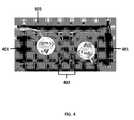
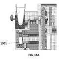
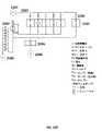
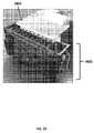
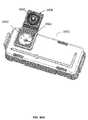
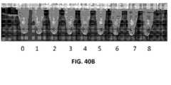
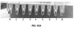
本開示の分析装置は、生体試料などの試料を処理及び/又は分析するために使用することができる。本開示の分析装置は携帯可能であってもよい。例えば、分析装置は手持ち式であってもよい。図1A~図1Bは、生体試料を分析するための携帯型分析装置用のハウジング100の(A)斜視図及び(B)側面図を示す。ハウジングは、蓋101、蓋を開位置又は閉位置に固定するための固定ユニット102、及び/又は、ボタン又はインジケータ103~106を有することができる。ハウジング100は、装置の電源をオン/オフするためのボタン103を備えることができる。ハウジング100は、装置を再起動するためのボタン104を備えることができる。ハウジング100は、バッテリ残量が少ないことをユーザに通知するためのインジケータ105及び/又は分析装置とモバイル電子機器との間に無線接続(例えば、ブルートゥース(登録商標)又は近距離無線通信接続)が確立されたことを示すインジケータ106を備えてもよい。場合によっては、本明細書に記載の分析装置は、試料処理及び分析のためのシステム内の分析ユニットとなり得る。分析ユニットは、試料調製ユニット(例えば、本明細書中に記載の試料調製装置)の同じハウジング内にあり得る。Analytical Devices The analytical devices of the present disclosure can be used to process and/or analyze samples, such as biological samples. The analytical device of the present disclosure may be portable. For example, the analyzer may be handheld. 1A-1B show (A) a perspective view and (B) a side view of a
分析装置は、作動時に分析装置(例えば、装置の電源をオン/オフすること、又は分析装置を他の装置に接続すること)の操作性に影響を及ぼすことができる少なくとも1つのボタンを備えることができる。分析装置は、1、2、3、4、5個又はそれ以上のボタンを備えてもよい。例えば、分析装置は4つのボタンを備えることができる。各ボタンは、分析装置の異なる機能又は特徴に対応することができる。場合によっては、ボタンの対は、分析装置の同じ機能又は特徴に対応し得る。例えば、分析装置は、値、ズームレベル、音量、又は、他の特性を増加させるためのボタン、並びに、同じ値、ズームレベル、音量、又は、他の特性を減少させるためのボタンを含むことができる。 The analytical device comprises at least one button that, when activated, can affect the operability of the analytical device (e.g., powering on/off the device or connecting the analytical device to other devices). can be done. The analyzer may have 1, 2, 3, 4, 5 or more buttons. For example, an analyzer can have four buttons. Each button can correspond to a different function or feature of the analyzer. In some cases, pairs of buttons may correspond to the same function or feature of the analyzer. For example, the analysis device may include a button to increase a value, zoom level, volume or other property and a button to decrease the same value, zoom level, volume or other property. can.
ボタン機構は、物理的機構であってもよい。例えば、ボタンは、ボタン又はマイクロスイッチなどの押下可能な機構を備えることができる。或いは、ボタンは、摺動可能又は回転可能な機構を備えてもよい。2つ以上のボタンを含む分析装置の場合、各ボタンは、押下可能機構、スライド可能機構、及び、回転可能機構から成るグループから別々に選択されてもよい。 A button mechanism may be a physical mechanism. For example, a button may comprise a depressible mechanism such as a button or microswitch. Alternatively, the button may comprise a slidable or rotatable mechanism. For analyzers that include more than one button, each button may be separately selected from the group consisting of depressible, slidable, and rotatable mechanisms.
ボタンは、タッチ感知機能又は機構を備えてもよい。例えば、図1A及び図1Bのボタン103及び104は、タッチ感知機能又は機構を備えることができる。タッチ感知機構は、タッチ感知仮想機構(例えば、仮想ボタン)であってもよい。そのような仮想機構は、仮想的に押し下げ可能、仮想的にスライド可能、又は、仮想的に回転可能であってもよく、それによって物理的ボタンの錯覚を与える。例えば、分析装置は、分析装置に対する無線接続部と通信可能に結合されたモバイル電子機器を備えてもよく又はモバイル電子機器を受け入れるように構成されてもよく、また、モバイル電子機器が1つ以上の仮想ボタンを備えてもよい。モバイル電子機器の仮想ボタンの押下は、モバイル電子機器から分析装置に信号を送信することができ、それによって、例えば、本明細書に記載の熱サイクリングプログラム又は他のプロセスに影響を及ぼす。分析装置とモバイル電子機器との間の接続は、WiFi接続、Bluetooth接続、Bluetooth LE接続、ANT+接続、又はGazell接続などの一方向又は双方向の有線又は無線接続を含むことができる。 The buttons may have touch-sensitive features or mechanisms. For example,
分析装置は、分析装置のハウジングの外面のどこかに配置された1つ以上のボタンを備えてもよい。例えば、ボタンは、分析装置のハウジングの前面、背面、右側、左側、上面、又は、底面に配置されてもよい。ボタンは、分析装置の動作中に利用できないか隠される場所(例えば、分析装置のハウジングの底部側)に配置されてもよい。場合によっては、パネルを使用して、1つ以上のボタンを覆うか隠すことができる(例えば、分析装置が使用されていないとき、及び/又は、ボタンの偶発的な作動を防止するために)。 The analyzer may include one or more buttons located anywhere on the exterior surface of the analyzer housing. For example, the buttons may be located on the front, back, right, left, top, or bottom of the housing of the analyzer. The button may be located in a location that is unavailable or hidden during operation of the analyzer (eg, on the bottom side of the analyzer housing). In some cases, panels can be used to cover or hide one or more buttons (e.g., when the analyzer is not in use and/or to prevent accidental actuation of the buttons). .
1つ以上のボタンの作動又は起動は、ユーザが複数の異なる熱サイクルプログラム間でサイクルできるようにしてもよい。例えば、ボタンの作動によって、分析装置は、第1の熱サイクルプログラムの実行から第2の熱サイクルプログラムへの切り替えを行なうことができる。別の例では、ボタンの作動は、分析装置を「オフ」状態から第1の熱サイクルプログラムの実行に切り替えることができる。2回目のボタンの作動により、分析装置は、第1の熱サイクルプログラムの実行から「オフ」状態に切り替えることができる。「オフ」状態は、アイドル状態(例えば、分析装置はオンであってもよいが、熱サイクリングプログラムが一時停止されている、又は、分析装置が最小電力状態にある)又は電源が切られた状態(例えば、分析装置の電源が切られている場合)を指すことができることが理解されるべきである。ボタンの作動は、熱サイクルプログラムのパラメータに影響を及ぼし得る。例えば、分析装置は、押し下げ可能な機構を含むことができ、押し下げ可能な機構の作動は、熱サイクリングプログラムを変性ステップからアニーリングステップに切り替えることができる。別の例では、分析装置が回転可能な機構を備えることができ、回転可能な機構の回転は熱サイクリング温度を上昇させることができる。場合によっては、2つ以上のボタンの作動が熱サイクルプログラムに影響を及ぼすことがある。 Actuation or activation of one or more buttons may allow the user to cycle between different thermal cycling programs. For example, actuation of a button can cause the analyzer to switch from running a first thermal cycling program to a second thermal cycling program. In another example, actuation of a button can switch the analyzer from an "off" state to running a first thermal cycling program. A second actuation of the button allows the analyzer to switch from executing the first thermal cycling program to the "off" state. An "off" state is an idle state (e.g., the analyzer may be on but a thermal cycling program is suspended, or the analyzer is in a minimum power state) or powered off. (eg, when the analyzer is turned off). Activation of the button can affect the parameters of the thermal cycling program. For example, the analyzer can include a depressible mechanism, and actuation of the depressible mechanism can switch the thermal cycling program from a denaturation step to an annealing step. In another example, the analytical device can include a rotatable mechanism, and rotation of the rotatable mechanism can increase the thermal cycling temperature. In some cases, actuation of more than one button may affect the thermal cycling program.
入力の程度は、熱サイクリングプログラムの状態に影響を及ぼし得る。変更され得る入力の程度の非限定的な例としては、入力の数(例えば、ボタンが連続して作動及び解放される回数)、入力の速度(例えば、ボタンが作動及び/又は解放される速度)、入力の持続時間(例えば、ボタンが作動される時間の量)、入力に加えられる力(例えば、ボタンを作動させる力)、及び、入力の方向が挙げられる。入力は、ボタンの作動を含むことができる。一例では、分析装置は、押下可能な機構を備えてもよく、短時間(例えば、1/2の半分未満)の押下及びその後の押下可能な機構の解放は、熱サイクリングプログラムを一時停止させてもよい。別の例では、一時停止された熱サイクリングプログラムは、例えば1~2秒間押し下げ可能な機構を押し下げることによって再開することができる。 The degree of input can affect the state of the thermal cycling program. Non-limiting examples of the degree of input that can be varied include the number of inputs (e.g., the number of times a button is successively actuated and released), the speed of input (e.g., the speed at which a button is actuated and/or released). ), the duration of the input (eg, the amount of time the button is activated), the force applied to the input (eg, the force that activates the button), and the direction of the input. The input can include button actuation. In one example, the analytical device may comprise a depressible mechanism, wherein pressing for a short period of time (e.g., less than one-half) and then releasing the depressible mechanism suspends the thermal cycling program. good too. In another example, a paused thermal cycling program can be resumed by depressing the depressible mechanism for, eg, 1-2 seconds.
分析装置は、試料を収容する1つ以上の容器を受け入れるように構成され得る。例えば、分析装置は、1つ以上の分析管を受け入れるように構成されてもよい。本開示の分析装置と共に使用するための分析管は、任意の有用なサイズ及び形状を有し、任意の有用な材料を含むことができる。例えば、分析管は、プラスチック、ポリマー、又は、ガラスを含み得る。分析装置は、実質的に円筒形である、実質的に長方形である、又は、任意の他の形状(例えば、星形)を成す断面を有する分析管を受け入れるように構成され得る。分析装置は、分析装置内への分析管の配置を容易にするために、分析管の一端に又は分析管の寸法に沿って配置された溝又は突起などの機械的キー要素を有する分析管を受け入れるように構成され得る。例えば、分析管は、その長さに沿って実質的に長方形の突起を備えることができ、また、分析装置は、特定の向きで分析管を受け入れるように構成された対応する窪みを備えることができる。分析装置は、キャップ又は蓋を有する分析管を受け入れるように構成され得る。或いは、分析装置は、分析管が分析装置内に配置されるときに分析管の開口を覆うように構成された構成要素を備えてもよい。分析装置は、1つ以上の分析管を受け入れるように構成されてもよい。例えば、分析装置は、1、2、3、4、5、6、7、8、9個又はそれ以上の分析管を受け入れるように構成され得る。 The analyzer can be configured to receive one or more containers containing samples. For example, an analysis device may be configured to receive one or more analysis tubes. Analysis tubes for use with the analytical devices of the present disclosure can have any useful size and shape and can comprise any useful material. For example, analysis tubes may comprise plastic, polymer, or glass. The analysis device may be configured to receive an analysis tube having a cross-section that is substantially cylindrical, substantially rectangular, or has any other shape (eg, star-shaped). The analyzer includes an analyzer tube having mechanical keying elements such as grooves or protrusions located at one end of the analyzer tube or along the dimensions of the analyzer tube to facilitate placement of the analyzer tube within the analyzer. can be configured to accept For example, an analysis tube can include substantially rectangular projections along its length and an analysis device can include a corresponding recess configured to receive the analysis tube in a particular orientation. can. The analysis device may be configured to receive analysis tubes having caps or lids. Alternatively, the analysis device may comprise a component configured to cover the opening of the analysis tube when the analysis tube is positioned within the analysis device. The analysis device may be configured to receive one or more analysis tubes. For example, an analysis device may be configured to accept 1, 2, 3, 4, 5, 6, 7, 8, 9 or more analysis tubes.
本明細書中に記載の装置は、試薬管又はカートリッジを受けるための表面又は支持体を有することができる。カートリッジは、試薬カートリッジとすることができる。表面又は支持体は、凹面又は支持体となり得る。表面は、突出した表面又は支持体となり得る。表面はチャンバとなり得る。カートリッジは、表面又は支持体に装填することができる。カートリッジを表面又は支持体に装填すると、蓋を閉じてカートリッジを定位置にクリックすることができる。 The devices described herein can have a surface or support for receiving reagent tubes or cartridges. The cartridge can be a reagent cartridge. A surface or support can be a concave surface or support. The surface can be a protruding surface or support. A surface can be a chamber. Cartridges can be surface or support loaded. Once the cartridge is loaded onto a surface or support, the lid can be closed and the cartridge clicked into place.
図1Cに示すように、分析装置のハウジング100の蓋101の内面は、分析装置の加熱ブロックに着座した1つ以上の分析管に圧力を加えることができる1つ以上のカンチレバー107を備えることができる。カンチレバーは、試料を収容する分析管を加熱ブロックに対して固定し、それによって加熱ブロックと分析管との間のエネルギー伝達の効率を高めるのに有用であり得る。カンチレバーを加熱して(例えば、加熱ブロックの温度に等しい温度で)、加熱ブロックと接触していない分析管の一部を加熱することができる。カンチレバーは任意の温度に加熱されてもよく、カンチレバーの温度は熱サイクルを通して変化してもよい。例えば、カンチレバーの温度は、熱サイクル全体を通して加熱ブロックの温度に(例えば、加熱ブロックの温度と同じになるように)調整されてもよい。図1Dに示すように、分析装置のハウジング100の蓋101の内面は、装置に挿入されたカートリッジを受ける又は収容するための凹面108を備えてもよい。分析装置のハウジング100の本体109の内面は、装置に挿入されたカートリッジを受けるための突出面110を備えてもよい。 As shown in FIG. 1C, the inner surface of the
分析装置は携帯可能であってもよい。例えば、ハウジングを含む分析装置は、容易に持ち運び又は移動することができる。ハウジング及び/又は他の構成要素のサイズ、重量、及び/又は、形状は、分析装置の可搬性に影響を及ぼし得る。分析装置のハウジングの体積は、約100,000立方センチメートル未満、約50,000立方センチメートル未満、約10,000立方センチメートル未満、約9,000立方センチメートル未満、約8,000立方センチメートル未満、約7,000立方センチメートル未満、約6,000立方センチメートル未満、約5,000立方センチメートル未満、約4,500立方センチメートル未満、約4,000立方センチメートル未満、約3,500立方センチメートル未満、約3,000立方センチメートル未満、約2,500立方センチメートル未満、約2,000立方センチメートル未満、約1,500立方センチメートル未満、約1,400立方センチメートル未満、約1,300立方センチメートル未満、約1,200立方センチメートル未満、約1,100立方センチメートル未満、約1,000立方センチメートル未満、約900立方センチメートル未満、約800立方センチメートル未満、約700立方センチメートル未満、約600立方センチメートル未満、又は約500立方センチメートル未満であってもよい。例えば、分析装置のハウジングの体積は、約1,500立方センチメートル未満であってもよい。分析装置のハウジングの体積は、ある範囲内にあってもよい。例えば、分析装置のハウジングの体積は、約500立方センチメートル~約1,500立方センチメートルであってもよい。ハウジングの寸法(例えば、長さ、幅又は高さ)は、最大で約50センチメートル、最大で約40センチメートル、最大で約30センチメートル、最大で約25センチメートル、最大で約24センチメートル、最大で約23センチメートル、最大で約22センチメートル、最大で約21センチメートル、最大で約20センチメートル、最大で約19センチメートル、最大で約18センチメートル、最大で約17センチメートル、最大で約16センチメートル、最大で約15センチメートル、最大で約14センチメートル、最大で約13センチメートル、最大で約12センチメートル、最大で約11センチメートル、最大で約10センチメートル、最大で約9センチメートル、最大で約8センチメートル、最大で約7センチメートル、最大で約6センチメートル、又は、最大で約5センチメートルであってもよい。 The analyzer may be portable. For example, an analytical device including a housing can be easily carried or moved. The size, weight and/or shape of the housing and/or other components can affect the portability of the analytical device. the volume of the housing of the analyzer is less than about 100,000 cubic centimeters, less than about 50,000 cubic centimeters, less than about 10,000 cubic centimeters, less than about 9,000 cubic centimeters, less than about 8,000 cubic centimeters, less than about 7,000 cubic centimeters; less than about 6,000 cubic centimeters, less than about 5,000 cubic centimeters, less than about 4,500 cubic centimeters, less than about 4,000 cubic centimeters, less than about 3,500 cubic centimeters, less than about 3,000 cubic centimeters, less than about 2,500 cubic centimeters, about Less than 2,000 cubic centimeters Less than about 1,500 cubic centimeters Less than about 1,400 cubic centimeters Less than about 1,300 cubic centimeters Less than about 1,200 cubic centimeters Less than about 1,100 cubic centimeters Less than about 1,000 cubic centimeters About 900 It may be less than about 800 cubic centimeters, less than about 700 cubic centimeters, less than about 600 cubic centimeters, or less than about 500 cubic centimeters. For example, the volume of the housing of the analytical device may be less than about 1,500 cubic centimeters. The volume of the housing of the analyzer may lie within a range. For example, the volume of the housing of the analytical device may be from about 500 cubic centimeters to about 1,500 cubic centimeters. The dimensions (e.g., length, width or height) of the housing are up to about 50 centimeters, up to about 40 centimeters, up to about 30 centimeters, up to about 25 centimeters, up to about 24 centimeters. , up to about 23 cm, up to about 22 cm, up to about 21 cm, up to about 20 cm, up to about 19 cm, up to about 18 cm, up to about 17 cm, up to about 16 cm, up to about 15 cm, up to about 14 cm, up to about 13 cm, up to about 12 cm, up to about 11 cm, up to about 10 cm, up to about 9 cm, up to about 8 cm, up to about 7 cm, up to about 6 cm, or up to about 5 cm.
ハウジングを含む分析装置の重量は、約25キログラム未満、約20キログラム未満、約15キログラム未満、約10キログラム未満、約5キログラム未満、約4.5キログラム未満、約4キログラム未満、約3.5キログラム未満、約3キログラム未満、約2.5キログラム未満、約2.4キログラム未満、約2.3キログラム未満、約2.2キログラム未満、約2.1キログラム未満、約2キログラム未満、約1.9キログラム未満、約1.8キログラム未満、約1.7キログラム未満、約1.6キログラム未満、約1.5キログラム未満、約1.4キログラム未満、約1.3キログラム未満、約1.2キログラム未満、約1.1キログラム未満、約1キログラム未満、約0.9キログラム未満、約0.8キログラム未満、約0.7キログラム未満、約0.6キログラム未満、約0.5キログラム未満、約0.4キログラム未満、約0.3キログラム未満、約0.2キログラム未満、約0.1キログラム未満であってもよい。例えば、分析装置のハウジングの体積は、約1.5キログラム未満であってもよい。ハウジングを含む分析装置の重量は、ある重量の範囲内にあってもよい。例えば、ハウジングを含む分析装置の重量は、約0.5キログラム~約1.5キログラムであってもよい。 The analytical device including the housing weighs less than about 25 kilograms, less than about 20 kilograms, less than about 15 kilograms, less than about 10 kilograms, less than about 5 kilograms, less than about 4.5 kilograms, less than about 4 kilograms, about 3.5 kilograms. less than about 3 kilograms, less than about 2.5 kilograms, less than about 2.4 kilograms, less than about 2.3 kilograms, less than about 2.2 kilograms, less than about 2.1 kilograms, less than about 2 kilograms, about 1 less than .9 kilograms, less than about 1.8 kilograms, less than about 1.7 kilograms, less than about 1.6 kilograms, less than about 1.5 kilograms, less than about 1.4 kilograms, less than about 1.3 kilograms; less than 2 kilograms, less than about 1.1 kilograms, less than about 1 kilogram, less than about 0.9 kilograms, less than about 0.8 kilograms, less than about 0.7 kilograms, less than about 0.6 kilograms, less than about 0.5 kilograms , less than about 0.4 kilograms, less than about 0.3 kilograms, less than about 0.2 kilograms, less than about 0.1 kilograms. For example, the analytical device housing may have a volume of less than about 1.5 kilograms. The weight of the analytical device, including the housing, may be within a certain weight range. For example, the weight of the analytical device including the housing may be from about 0.5 kilograms to about 1.5 kilograms.
分析装置のハウジングの形状も分析装置の可搬性に寄与し得る。ハウジングの少なくとも1つの寸法(例えば、長さ、幅又は高さ)は、ハウジングが人間の手によって容易に把持され得るように十分に小さくてもよい。分析装置は、ユーザが片手又は両手で分析装置を保持できるようにするサイズの人間工学的に成形されたハウジングを有することができる。ハウジングは、把持領域、例えば、ユーザが分析装置を保持するときにユーザによって把持されるハウジングの一部を備えてもよい。ハウジングの把持領域は、ユーザの指に適合するように成形することができ、それによってユーザがハウジングでしっかりと把持できるようにする。分析装置のハウジングの前面は、前面の上端セクション又は下端セクションよりも把持領域に関連する中央セクションで狭くてもよい。より狭いセクションは、ユーザによって都合良く且つ確実に把持され得るが、比較的広い上端セクションは、ディスプレイ装置又はその構成要素、例えばスクリーンを含み得る。ハウジングは、人間工学的に成形することができる格納式ハンドルを備えることができる。分析装置のハウジングは、ユーザが分析装置を保持するときに、ユーザの手が鋭い角ではなく丸みを帯びた角に接触することができるように、丸みを帯びた角及び/又は縁部(例えば、垂直面が交わる場合)を特徴とすることができる。 The shape of the analyzer housing can also contribute to the portability of the analyzer. At least one dimension (eg, length, width or height) of the housing may be small enough so that the housing can be easily grasped by a human hand. The analyzer can have an ergonomically shaped housing sized to allow a user to hold the analyzer with one or both hands. The housing may comprise a gripping area, eg, a portion of the housing that is gripped by the user when the user holds the analytical device. The gripping area of the housing can be molded to fit a user's fingers, thereby allowing the user to firmly grip the housing. The front face of the housing of the analyzer may be narrower in the central section associated with the gripping area than the top or bottom section of the front face. A narrower section may be conveniently and securely gripped by the user, while a relatively wide top section may contain the display device or its components, such as the screen. The housing can include a retractable handle that can be ergonomically shaped. The analyzer housing may have rounded corners and/or edges (e.g., , where the vertical planes meet).
図9は、試料分析のために試料カートリッジ901が装置に挿入された例示的な携帯型装置を示す。内部機構200の斜視図が示されている。図13は、試料分析のために試料管1301が装置に挿入された携帯用装置1300の別の例を示す。 FIG. 9 shows an exemplary portable device with a
熱サイクリング
分析装置は、分析管内の試料を加熱又は冷却するように構成され得る。図2に示すように、分析装置200は、試料を収容する分析管が配置される1つ以上の加熱ブロック201を備えることができる。分析装置は、ヒータ202(例えば、抵抗ヒータ)を使用して加熱ブロックの温度を離散的なステップで上昇又は下降させるように構成されてもよい。A thermal cycling analyzer can be configured to heat or cool a sample in an analysis tube. As shown in FIG. 2, the
場合によっては、加熱ブロックは、抵抗加熱又はジュール加熱のプロセスによって電気エネルギーを熱に変換することができる。加熱ブロックは抵抗ヒータとすることができる。加熱されたブロックは、試料チャンバと熱連通するように、電力抵抗器(例えば、サーミスタ)、熱エポキシを有することができる。加熱ブロックは、水平で均一であってもよい。加熱ブロックの冷却は、ファンによって達成又は制御することができる。例えば、図4は、回路基板を取り外し、それによって内部機構のファン402を露出させた携帯型分析装置用の内部機構の背面図を示す。 In some cases, the heating block can convert electrical energy into heat through resistive heating or Joule heating processes. The heating block can be a resistance heater. The heated block can have power resistors (eg, thermistors), thermal epoxy to be in thermal communication with the sample chamber. The heating block may be horizontal and uniform. Cooling of the heating block can be achieved or controlled by a fan. For example, FIG. 4 shows a rear view of the internals for a portable analyzer with the circuit board removed, thereby exposing the
場合によっては、加熱ブロックはペルチェヒータとすることができる。加熱及び冷却は、ペルチェコントローラによって達成又は制御することができる。幾つかの他の場合では、加熱ブロックがペルチェヒータでなくてもよく、又は、加熱ブロックはペルチェコントローラによって制御されなくてもよい。 In some cases, the heating block can be a Peltier heater. Heating and cooling can be accomplished or controlled by a Peltier controller. In some other cases, the heating block may not be a Peltier heater, or the heating block may not be controlled by a Peltier controller.
分析装置は、1つ以上の加熱ブロックを備えてもよい。場合によっては、2つ以上の加熱ブロックは、独立しているか、接続されていないか、又は、互いに分離されている(例えば、図20A及び図20Bに示すような単一ブロックモデル/構成)。例えば、隣接する2つの加熱ブロックの間に隙間領域が存在するように、加熱ブロックと隣接する加熱ブロックとが接続されていなくてもよい。2つ以上の加熱ブロックは、装置内に個別に設置されてもよい。図20Aは、分析装置の回路基板2001に設置された複数の個々の加熱ブロック2002を示す。 The analyzer may comprise one or more heating blocks. In some cases, two or more heating blocks are independent, unconnected, or separated from each other (eg, single block models/configurations as shown in FIGS. 20A and 20B). For example, a heating block and an adjacent heating block may not be connected such that there is an interstitial region between two adjacent heating blocks. Two or more heating blocks may be placed individually within the device. FIG. 20A shows a plurality of
場合によっては、2つ以上の個々の加熱ブロックが接続される。場合によっては、2つ以上の加熱ブロックが接続されて、加熱ブロックのストリップ(例えば、図20C及び図20Dに示すモノリシックブロックモデル/構成)を形成する。複数の個々の加熱ブロックを互いに接触させて、単一の加熱ユニット(例えば、モノリシック加熱ブロック)を得ることができる。個々の加熱ブロックは、同じ材料又は異なる材料で形成されてもよい。隣接する加熱ブロックは、互いに直接接触していてもよい。隣接する加熱ブロックは、熱伝導性材料(例えば、熱伝導性エポキシ)を介して互いに接触してもよい。 In some cases, two or more individual heating blocks are connected. In some cases, two or more heating blocks are connected to form a strip of heating blocks (eg, the monolithic block model/configuration shown in Figures 20C and 20D). A plurality of individual heating blocks can be brought into contact with each other to obtain a single heating unit (eg a monolithic heating block). Individual heating blocks may be formed of the same material or different materials. Adjacent heating blocks may be in direct contact with each other. Adjacent heating blocks may contact each other via a thermally conductive material (eg, thermally conductive epoxy).
モノリシック加熱ブロックは、複数の加熱サブユニット(例えば、各サブユニットは、個々の加熱ブロックと同等の機能を有することができる)を備えることができる。加熱サブユニットは、同じ材料から(例えば、モノリシック物体から材料を除去して凹部を生成することによって)形成されてもよい。例えば、図20Cは、複数の加熱サブユニットが分析装置の回路基板2003に設置されたモノリシック加熱ブロック2004を示す。 A monolithic heating block can comprise multiple heating subunits (eg, each subunit can have the same functionality as an individual heating block). The heating subunits may be formed from the same material (eg, by removing material from the monolithic body to create recesses). For example, FIG. 20C shows a
加熱ブロックは、加熱ブロックと隣接する1つ以上の加熱ブロックとの間に隙間領域が存在しないように、隣接する1つ以上の加熱ブロックに接続することができる。2つの隣接する加熱ブロック間の隙間領域は、2つの隣接する加熱ブロックを接続するために固体材料で充填されてもよい。場合によっては、隙間領域の全体積が固体材料で充填される。場合によっては、隙間領域の一部が固体材料で充填される。例えば、隣接する加熱ブロックを接続するために、隙間領域の全体積の少なくとも約1%、2%、3%、4%、5%、6%、7%、8%、9%、10%、11%、12%、13%、14%、15%、16%、17%、18%、19%、20%、21%、22%、23%、24%、25%、26%、27%、28%、29%、30%、31%、32%、33%、34%、35%、36%、37%、38%、39%、40%、41%、42%、43%、44%、45%、46%、47%、48%、49%、50%、51%、52%、53%、54%、55%、56%、57%、58%、59%、60%、61%、62%、63%、64%、65%、66%、67%、68%、69%、70%、71%、72%、73%、74%、75%、76%、77%、78%、79%、80%、81%、82%、83%、84%、85%、86%、87%、88%、89%、90%、91%、92%、93%、94%、95%、96%、97%、98%、99%、又は、それ以上が固体材料で充填され得る。隙間領域内の固体材料は、様々な形態に成形することができる。例えば、隙間領域内の固体材料は、隣接する加熱ブロックを接続する1つ以上のブリッジを形成することができる。例えば、隙間領域内の固体材料は、中空構造を有してもよい。隙間領域内の固体材料は、1つ以上の穴を備えることができる。固体材料は、様々な材料となり得る。固体材料は、本明細書に記載の加熱ブロックを作製するために使用される材料と同じ材料又は異なる材料であってもよい。隙間領域内の固体材料として使用され得る材料の非限定的な例としては、アルミニウム、コンクリート、ガラス、石英、鋼、鉄、ニッケル、亜鉛、銅、真鍮、銀、スズ、金、炭素、及びそれらの任意の組み合わせ(例えば、Zamakなどの亜鉛合金)が挙げられる。 A heating block can be connected to one or more adjacent heating blocks such that there are no interstitial regions between the heating block and one or more adjacent heating blocks. The interstitial area between two adjacent heating blocks may be filled with a solid material to connect the two adjacent heating blocks. In some cases, the entire volume of the interstitial region is filled with solid material. In some cases, a portion of the interstitial region is filled with solid material. For example, at least about 1%, 2%, 3%, 4%, 5%, 6%, 7%, 8%, 9%, 10% of the total interstitial area volume to connect adjacent heating blocks, 11%, 12%, 13%, 14%, 15%, 16%, 17%, 18%, 19%, 20%, 21%, 22%, 23%, 24%, 25%, 26%, 27% , 28%, 29%, 30%, 31%, 32%, 33%, 34%, 35%, 36%, 37%, 38%, 39%, 40%, 41%, 42%, 43%, 44% %, 45%, 46%, 47%, 48%, 49%, 50%, 51%, 52%, 53%, 54%, 55%, 56%, 57%, 58%, 59%, 60%, 61%, 62%, 63%, 64%, 65%, 66%, 67%, 68%, 69%, 70%, 71%, 72%, 73%, 74%, 75%, 76%, 77% , 78%, 79%, 80%, 81%, 82%, 83%, 84%, 85%, 86%, 87%, 88%, 89%, 90%, 91%, 92%, 93%, 94% %, 95%, 96%, 97%, 98%, 99% or more can be filled with solid material. The solid material within the interstitial region can be shaped into various shapes. For example, the solid material in the interstitial regions can form one or more bridges connecting adjacent heating blocks. For example, the solid material within the interstitial region may have a hollow structure. The solid material within the interstitial region may comprise one or more holes. A solid material can be a variety of materials. The solid material may be the same material used to make the heating blocks described herein or a different material. Non-limiting examples of materials that can be used as the solid material in the interstitial region include aluminum, concrete, glass, quartz, steel, iron, nickel, zinc, copper, brass, silver, tin, gold, carbon, and the like. (eg, zinc alloys such as Zamak).
場合によっては、個々の又は接続されていないブロック(例えば、図20Aに示すように、単一のブロック)を有する装置は、接続された加熱ブロック(例えば、図20Cに示すようなモノリシックブロック)を有する装置よりも速く(例えば、より高い加熱速度で)加熱され得る。図21Aは、単一ブロック装置及びモノリシックブロック装置のピーク加熱速度の例示的なヒストグラムを示す。この例では、99個の単一ブロック装置及び11個のモノリシックブロック装置が試験された。装置をMasterbond Supreme 18TCエポキシで硬化した。温度を50℃~100℃の間でサイクルさせた。比較すると、単一ブロック装置は、モノリシックブロック装置よりも速く加熱された(又はより大きい加熱速度を有した)。 In some cases, a device with individual or unconnected blocks (eg, a single block as shown in FIG. 20A) may include a connected heating block (eg, a monolithic block as shown in FIG. 20C). It can be heated faster (eg, at a higher heating rate) than the device with. FIG. 21A shows exemplary histograms of peak heating rates for single block devices and monolithic block devices. In this example, 99 single block devices and 11 monolithic block devices were tested. The device was cured with Masterbond Supreme 18TC epoxy. The temperature was cycled between 50°C and 100°C. By comparison, the single block device heated faster (or had a greater heating rate) than the monolithic block device.
モノリシックブロックの加熱速度は、接続されていないブロックの加熱速度よりも小さくてもよい。しかしながら、モノリシックブロックの冷却速度は、接続されていないブロックの冷却速度よりも大きくてもよい。例えば、モノリシックブロックの冷却速度は、接続されていないブロックの冷却速度よりも少なくとも1%、5%、10%、20%、30%、40%、50%、60%、70%、80%、90%、又はそれ以上大きくてもよい。 The heating rate of monolithic blocks may be lower than that of unconnected blocks. However, the cooling rate of monolithic blocks may be greater than the cooling rate of unconnected blocks. For example, the cooling rate of monolithic blocks is at least 1%, 5%, 10%, 20%, 30%, 40%, 50%, 60%, 70%, 80%, It may be 90% or more.
2つ以上の加熱ブロックを接続して、冷却中に2つ以上の接続されていない加熱ブロックよりも効率的な熱交換を容易にすることができる。例えば、2つ以上の加熱ブロックは、非接続形態にある場合、各加熱ブロックの中心に熱を閉じ込め、所定の温度に達するための冷却時間を長くすることができる。2つ以上の加熱ブロックが接続されると、冷却中に所定の温度を達成するのに要する時間が短くなり得る。図21Bは、単一ブロック装置及びモノリシックブロック装置のピーク冷却速度の例示的なヒストグラムを示す。この例では、99個の単一ブロック装置及び11個のモノリシックブロック装置が試験された。装置をMasterbond Supreme 18TCエポキシで硬化した。温度を50℃~100℃の間でサイクルさせた。比較すると、モノリシックブロック装置は、シングルブロック装置よりも速く冷却された。 Two or more heating blocks can be connected to facilitate more efficient heat exchange during cooling than two or more unconnected heating blocks. For example, two or more heating blocks, when in a disconnected configuration, can trap heat in the center of each heating block, increasing the cooling time to reach a predetermined temperature. When two or more heating blocks are connected, less time may be required to reach a given temperature during cooling. FIG. 21B shows exemplary histograms of peak cooling rates for single block devices and monolithic block devices. In this example, 99 single block devices and 11 monolithic block devices were tested. The device was cured with Masterbond Supreme 18TC epoxy. The temperature was cycled between 50°C and 100°C. By comparison, the monolithic block device cooled faster than the single block device.
個々のブロックを有する装置及び接続されたブロックを有する装置は、同等の加熱均一性を有することができる。均一性は、全ての時点について、最も熱いブロックから最も冷たいブロックを引いたものとして計算することができる。図21Cは、単一ブロック装置及びモノリシックブロック装置の加熱均一性の例示的なヒストグラムを示す。この例では、99個の単一ブロック装置及び11個のモノリシックブロック装置が試験された。装置をMasterbond Supreme 18TCエポキシで硬化した。温度を50℃~100℃の間でサイクルさせた。単一ブロック装置は、モノリシックブロック装置と加熱均一性に関して同様の性能を有していた。個々のブロックを有する装置及び接続されたブロックを有する装置は、同等の冷却均一性を有さなくてもよい。図21Dは、単一ブロック装置及びモノリシックブロック装置の冷却均一性の例示的なヒストグラムを示す。この例では、99個の単一ブロック装置及び11個のモノリシックブロック装置が試験された。装置をMasterbond Supreme 18TCエポキシで硬化した。温度を50℃~100℃の間でサイクルさせた。モノリシックブロック装置は、単一ブロック装置と比較して、冷却中の温度がより均一であった。図21Eは、単一ブロック装置及びモノリシックブロック装置の高温(約100℃)均一性の例示的なヒストグラムを示す。この例では、99個の単一ブロック装置及び11個のモノリシックブロック装置が試験された。装置をMasterbond Supreme 18TCエポキシで硬化した。加熱ブロックを100℃の温度に加熱した。単一ブロック装置は、モノリシックブロック装置と高温均一性に関して同様の性能を有していた。図21Fは、単一ブロック装置及びモノリシックブロック装置の低温(約50℃)均一性の例示的なヒストグラムを示す。この例では、99個の単一ブロック装置及び11個のモノリシックブロック装置が試験された。装置をMasterbond Supreme 18TCエポキシで硬化した。加熱ブロックを50℃の温度に加熱した。単一ブロック装置は、モノリシックブロック装置と低温均一性に関して同様の性能を有していた。 Devices with individual blocks and devices with connected blocks can have comparable heating uniformity. Homogeneity can be calculated as the hottest block minus the coldest block for all time points. FIG. 21C shows exemplary histograms of heating uniformity for single block devices and monolithic block devices. In this example, 99 single block devices and 11 monolithic block devices were tested. The device was cured with Masterbond Supreme 18TC epoxy. The temperature was cycled between 50°C and 100°C. The single block device had similar performance with respect to heating uniformity as the monolithic block device. Devices with individual blocks and devices with connected blocks may not have the same cooling uniformity. FIG. 21D shows exemplary histograms of cooling uniformity for single block devices and monolithic block devices. In this example, 99 single block devices and 11 monolithic block devices were tested. The device was cured with Masterbond Supreme 18TC epoxy. The temperature was cycled between 50°C and 100°C. The monolithic block device was more uniform in temperature during cooling compared to the single block device. FIG. 21E shows exemplary histograms of high temperature (approximately 100° C.) uniformity for single block devices and monolithic block devices. In this example, 99 single block devices and 11 monolithic block devices were tested. The device was cured with Masterbond Supreme 18TC epoxy. The heating block was heated to a temperature of 100°C. The single block device had similar performance with respect to high temperature uniformity as the monolithic block device. FIG. 21F shows exemplary histograms of low temperature (about 50° C.) uniformity for single block devices and monolithic block devices. In this example, 99 single block devices and 11 monolithic block devices were tested. The device was cured with Masterbond Supreme 18TC epoxy. The heating block was heated to a temperature of 50°C. The single block device had similar performance with respect to low temperature uniformity as the monolithic block device.
個々のブロックを有する装置及び接続されたブロックを有する装置は、同等の精度を有してもよく又は有さなくてもよい。精度は、所定の時点での平均反応ブロック温度と設定温度との差によって計算することができる。図21Gは、単一ブロック装置及びモノリシックブロック装置の高温での精度の例示的なヒストグラムを示す。この例では、99個の単一ブロック装置及び11個のモノリシックブロック装置が試験された。モノリシックブロック装置は、シングルブロック装置と比較して、高温でわずかに精度が低かった。図21Hは、単一ブロック装置及びモノリシックブロック装置の低温での精度の例示的なヒストグラムを示す。この例では、99個の単一ブロック装置及び11個のモノリシックブロック装置が試験された。モノリシックブロック装置は、単一ブロック装置と比較して、低温で同等の精度を有していた。 A device with individual blocks and a device with connected blocks may or may not have comparable accuracy. Accuracy can be calculated by the difference between the average reaction block temperature at a given point in time and the set temperature. FIG. 21G shows exemplary histograms of accuracy at high temperature for single block devices and monolithic block devices. In this example, 99 single block devices and 11 monolithic block devices were tested. The monolithic block device was slightly less accurate at elevated temperatures compared to the single block device. FIG. 21H shows exemplary histograms of accuracy at low temperature for single block devices and monolithic block devices. In this example, 99 single block devices and 11 monolithic block devices were tested. The monolithic block device had comparable accuracy at low temperatures compared to the single block device.
本明細書に記載の装置は、加熱された蓋を含んでも含まなくてもよい。 The devices described herein may or may not include a heated lid.
加熱ブロック201は、任意の有用な材料を含むことができる。加熱ブロックを構成するために使用され得る材料の非限定的な例としては、アルミニウム、コンクリート、ガラス、石英、鋼、鉄、ニッケル、亜鉛、銅、真鍮、銀、スズ、金、炭素、及び、それらの任意の組み合わせ(例えば、Zamakなどの亜鉛合金)が挙げられる。例えば、図3Aに示すように、銀を使用して加熱ブロックを構築することができる。別の例では、加熱ブロックは、図3Bに示すように、アルミニウムを使用して構成されてもよい。加熱ブロックは、試料(例えば、生体試料)を収容する又は収容するように構成されたバイアルを受け入れるための第1の開口301と、検出器又は光源(例えば、励起用)と光学的に連通するように構成された第2の開口302とを含んでもよい。加熱ブロックは、検出器又は光源と光学的に連通するように構成された第3の開口(図示せず)を含むことができる。例えば、第2の開口302は検出器と光学的に連通していてもよく、第3の開口(図示せず)は励起用光源と光学的に連通していてもよい。加熱ブロックは、1つ以上のフィン303を備えてもよい。
加熱ブロックは、合金で形成されてもよい。例えば、加熱ブロックは、鋼を使用して構築されてもよい。ダイカストのプロセスに適合する材料(例えば、加熱ブロックのダイカスト構造に使用することができる材料)を使用して加熱ブロックを構築することにより、加熱ブロックをより大規模に(例えば、より短い期間でより大量に、及び/又は単位当たりのコストを削減して)製造することができると考えられる。幾つかの実施形態では、加熱ブロックは、材料の組み合わせを使用して構成することができる。例えば、加熱ブロックは、アルミニウムを使用して構築され、続いてニッケルでコーティングされ得る。別の例では、加熱ブロックは、亜鉛を使用して構築され、銀でコーティングされ得る。加熱ブロックのコーティングは、幾つかの理由で有利となり得る。例えば、加熱ブロック(例えば、ニッケル)をコーティングすると、熱エポキシを使用するのとは対照的に、加熱ブロックをプリント回路基板(PCB)に半田付けすることができる。加熱ブロックをPCBに半田付けすることにより、取り外し可能な加熱ブロックを用いて分析装置を製造することができる(例えば、損傷の場合)が、熱エポキシを使用することにより、加熱ブロックをPCBに恒久的に取り付けることができる。加熱ブロックを製造するために使用される材料の選択は、分析装置が電源(例えば、バッテリなどの自己完結型電源)を使用して受けることができる熱サイクルの数に影響を及ぼし得ることが考えられる。特に、材料の比熱容量が高いほど、材料の温度を上昇させるためにより多くのエネルギーを使用することができる。したがって、約2J/g℃未満、約1.5J/g℃未満、約1J/g℃未満、約0.9J/g℃未満、約0.8J/g℃未満、約0.7J/g℃未満、約0.6J/g℃未満、約0.5J/g℃未満、約0.45J/g℃未満、約0.4J/g℃未満、約0.35J/g℃未満、約0.3J/g℃未満、約0.25J/g℃未満、約0.2J/g℃未満、約0.15J/g℃未満、約0.1J/g℃未満、約0.05J/g℃未満、又は、約0.01J/g℃未満の比熱容量(例えば、25℃において、ジュール/グラム/℃;J/g℃で測定した場合)を有する材料を使用して加熱ブロックを構築することができる。例えば、加熱ブロックは、25℃で約1J/g℃未満の比熱容量を有する材料を使用して構成することができる。 The heating block may be made of an alloy. For example, the heating block may be constructed using steel. By constructing the heating block using materials that are compatible with the die casting process (e.g., materials that can be used in the die-cast construction of the heating block), the heating block can be made larger (e.g., in a shorter period of time). It is believed that they can be manufactured in large quantities and/or at a reduced cost per unit). In some embodiments, the heating block can be constructed using a combination of materials. For example, the heating block may be constructed using aluminum and subsequently coated with nickel. In another example, the heating block may be constructed using zinc and coated with silver. Coating the heating block can be advantageous for several reasons. For example, coating the heating block (eg, nickel) allows the heating block to be soldered to a printed circuit board (PCB) as opposed to using thermal epoxy. By soldering the heating block to the PCB, the analyzer can be manufactured with a removable heating block (e.g., in case of damage), but using thermal epoxy permanently attaches the heating block to the PCB. can be installed properly. It is believed that the choice of materials used to fabricate the heating block can affect the number of thermal cycles the analyzer can undergo using a power source (e.g., a self-contained power source such as a battery). be done. In particular, the higher the specific heat capacity of a material, the more energy can be used to raise the temperature of the material. Therefore, less than about 2 J/g°C, less than about 1.5 J/g°C, less than about 1 J/g°C, less than about 0.9 J/g°C, less than about 0.8 J/g°C, about 0.7 J/g°C less than about 0.6 J/g°C, less than about 0.5 J/g°C, less than about 0.45 J/g°C, less than about 0.4 J/g°C, less than about 0.35 J/g°C, about 0. Less than 3 J/g°C, less than about 0.25 J/g°C, less than about 0.2 J/g°C, less than about 0.15 J/g°C, less than about 0.1 J/g°C, less than about 0.05 J/g°C Alternatively, the heating block can be constructed using a material that has a specific heat capacity of less than about 0.01 J/g°C (e.g., at 25°C when measured in Joules/gram/°C; J/g°C). can. For example, the heating block can be constructed using a material that has a specific heat capacity of less than about 1 J/g°C at 25°C.
更に、材料の熱伝導率が低いほど、より多くのエネルギーを使用して材料の温度を上昇させることができる。したがって、加熱ブロックは、少なくとも約500W/mK、少なくとも約400W/mK、少なくとも約300W/mK、少なくとも約200W/mK、少なくとも約175W/mK、少なくとも約150W/mK、少なくとも約125W/mK、少なくとも約100W/mK、少なくとも約75W/mK、少なくとも約50W/mK、少なくとも約25W/mK、又は、少なくとも約10W/mKの熱伝導率(例えば、ワット/メートル/ケルビンW/mKで測定した場合;)を有する材料を使用して構成することができる。例えば、加熱ブロックは、少なくとも約75W/mKの熱伝導率を有する材料を使用して構成することができる。別の例では、加熱ブロックは、少なくとも約400W/mKの熱伝導率を有する材料を使用して構成することができる。 Furthermore, the lower the thermal conductivity of the material, the more energy can be used to raise the temperature of the material. Thus, the heating block is at least about 500 W/mK, at least about 400 W/mK, at least about 300 W/mK, at least about 200 W/mK, at least about 175 W/mK, at least about 150 W/mK, at least about 125 W/mK, at least about A thermal conductivity of 100 W/mK, at least about 75 W/mK, at least about 50 W/mK, at least about 25 W/mK, or at least about 10 W/mK (e.g., when measured in Watts/meters/Kelvin W/mK;) can be constructed using materials having For example, the heating block can be constructed using a material having a thermal conductivity of at least about 75 W/mK. In another example, the heating block can be constructed using a material having a thermal conductivity of at least about 400 W/mK.
また、加熱ブロックは、加熱ブロックの表面積を増加させ、加熱ブロックからのより良好な放熱を行なうために、1つ以上のフィン303を備えることができる。加熱ブロックを形成するために使用される材料の体積は、分析装置が電源(例えば、バッテリなどの自己完結型電源)を使用して受けることができる熱サイクルの数に影響を及ぼし得ることも考えられる。特に、加熱ブロックを構築するために使用される材料の体積が大きいほど、加熱ブロックの温度を上昇させるためにより多くのエネルギーを使用することができる。したがって、加熱ブロックを構成するために使用される材料の体積は、約20立方センチメートル未満、約15立方センチメートル未満、約10立方センチメートル未満、約9立方センチメートル未満、約8立方センチメートル未満、約7立方センチメートル未満、約6立方センチメートル未満、約5立方センチメートル未満、約4立方センチメートル未満、約3立方センチメートル未満、約2立方センチメートル未満、約1立方センチメートル未満、約0.9立方センチメートル未満、約0.8立方センチメートル未満、約0.7立方センチメートル未満、約0.6立方センチメートル未満、約0.5立方センチメートル未満、約0.4立方センチメートル未満、約0.3立方センチメートル未満、約0.2立方センチメートル未満、又は約0.1立方センチメートル未満であってもよい。例えば、加熱ブロックを構築するために使用される材料の体積は、約0.5立方センチメートル未満であってもよい。 The heating block can also include one or
前述したように、加熱を構成するために使用される材料及び/又は材料の体積は、ブロックを加熱又は冷却するために使用されるエネルギーを最小化することに基づいて選択することができる。したがって、本開示の分析装置は、より大きな加熱ブロック、又はより高い比熱容量を有する材料を使用して構成された加熱ブロックを使用する装置と比較して、より多くの熱サイクルを実行するためにより多くのエネルギーを提供することができる。本開示の分析装置は、任意の数の熱サイクルを実行することができる。分析装置は、電源の単一の充電に対して所定の回数の熱サイクルを実行することができる(例えば、バッテリなどの自己完結型電源)。本開示の分析装置は、少なくとも約1熱サイクル、少なくとも約2熱サイクル、少なくとも約3熱サイクル、少なくとも約4熱サイクル、少なくとも約5熱サイクル、少なくとも約6熱サイクル、少なくとも約7熱サイクル、少なくとも約8熱サイクル、少なくとも約9熱サイクル、少なくとも約10熱サイクル、少なくとも約11熱サイクル、少なくとも約12熱サイクル、少なくとも約13熱サイクル、少なくとも約14熱サイクル、少なくとも約15熱サイクル、少なくとも約16熱サイクル、少なくとも約17熱サイクル、少なくとも約18熱サイクル、少なくとも約19熱サイクル、少なくとも約20熱サイクル、少なくとも約25熱サイクル、少なくとも約30熱サイクル、少なくとも約35熱サイクル、少なくとも約40熱サイクル、少なくとも約45熱サイクル、少なくとも約50熱サイクル、又は、少なくとも約100熱サイクルを実行し得る。本開示の分析装置は、約1~約10回の熱サイクル、約5~約15回の熱サイクル、約10~約20回の熱サイクル、又は、約15~約25回の熱サイクルを実行することができる。 As previously mentioned, the materials and/or volumes of materials used to make up the heating can be selected based on minimizing the energy used to heat or cool the block. Therefore, the analytical device of the present disclosure requires more heat to perform more thermal cycles compared to devices that use larger heating blocks or heating blocks constructed using materials with higher specific heat capacities. It can provide a lot of energy. The analytical device of the present disclosure can perform any number of thermal cycles. The analyzer can perform a predetermined number of thermal cycles on a single charge of the power source (eg self-contained power source such as a battery). Analytical devices of the present disclosure can perform at least about 1 thermal cycle, at least about 2 thermal cycles, at least about 3 thermal cycles, at least about 4 thermal cycles, at least about 5 thermal cycles, at least about 6 thermal cycles, at least about 7 thermal cycles, at least about about 8 thermal cycles, at least about 9 thermal cycles, at least about 10 thermal cycles, at least about 11 thermal cycles, at least about 12 thermal cycles, at least about 13 thermal cycles, at least about 14 thermal cycles, at least about 15 thermal cycles, at least about 16 thermal cycles, at least about 17 thermal cycles, at least about 18 thermal cycles, at least about 19 thermal cycles, at least about 20 thermal cycles, at least about 25 thermal cycles, at least about 30 thermal cycles, at least about 35 thermal cycles, at least about 40 thermal cycles , at least about 45 thermal cycles, at least about 50 thermal cycles, or at least about 100 thermal cycles. The analytical device of the present disclosure performs about 1 to about 10 thermal cycles, about 5 to about 15 thermal cycles, about 10 to about 20 thermal cycles, or about 15 to about 25 thermal cycles. can do.
本開示の分析装置は、(例えば、分析管内の試料の温度を循環させることによって)ポリメラーゼ連鎖反応(PCR)などの増幅反応を行なうように構成されていてもよい。PCRを実施することは、2つ又は3つの別個の温度ステップを含む各シリーズ(例えば、サイクル)で一連の反復温度変化(例えば、熱サイクル)を行なうことを含み得る。熱サイクルの前に、より高い温度(例えば、>90℃)での単一の温度ステップがあってもよい。各サイクルで使用される温度及びそれらが適用される時間の長さは、例えば、デオキシリボ核酸(DNA)合成に使用される酵素、反応中の二価イオン及びヌクレオチド(dNTP)の濃度、並びに、1つ以上のプライマーの融解温度(Tm)に基づいて変化し得る。PCRなどの増幅反応の個々のステップは、初期化、変性、アニーリング及び/又は拡張/伸長を含み得る。初期化は、熱によって活性化され得るDNAポリメラーゼのために使用され得る(例えば、「ホットスタート」PCR)。初期化は、試料(例えば、分析管内の試料)を高温(例えば、耐熱性ポリメラーゼが使用される場合には、94℃~96℃[201°F~205°F)又は98℃[208°F])に加熱することを含んでもよく、これは約1~10分間維持され得る。変性は、試料(例えば、分析管内の試料)を所定の時間、例えば約5秒~5分間(例えば、94~98℃[201~208°F]まで)加熱することを含んでもよい。これは、相補的な塩基間の水素結合を切断し、2つの一本鎖核酸分子(例えば、テンプレート)を生じることによって、二本鎖DNAテンプレートのDNA融解又は変性をもたらし得る。アニーリングは、所定の時間、例えば約5秒~5分間、試料(例えば、分析管内の試料)の温度を例えば50~65℃(122~149°F)に下げ、それによって一本鎖核酸テンプレートの各々への1つ以上のプライマーのアニーリングを可能にすることを含んでもよい。標的領域を含有する2つのそれぞれの一本鎖核酸テンプレートごとに1つを含めて、少なくとも2つの異なるプライマーを反応混合物に含めることができる。プライマーは、一本鎖核酸分子自体であってもよい。効果的な拡張/伸長に適した条件は、使用されるDNAポリメラーゼに依存し得る。拡張/伸長は、DNAポリメラーゼの存在下で、テンプレートに5’から3’方向に相補的な遊離dNTPを反応混合物から添加し、新生(伸長)DNA鎖の末端でdNTPの5’-リン酸基を3’-ヒドロキシ基と縮合させることによって、一本鎖核酸テンプレートに相補的な新しいDNA鎖を合成することを含む。拡張/伸長の時間は、使用されるDNAポリメラーゼ及び/又は増幅するDNA標的領域の長さに依存し得る。 An analytical device of the present disclosure may be configured to perform an amplification reaction such as the polymerase chain reaction (PCR) (eg, by cycling the temperature of the sample within the analytical tube). Performing PCR may involve performing a series of repetitive temperature changes (eg, thermal cycling) with each series (eg, cycle) comprising two or three separate temperature steps. There may be a single temperature step at a higher temperature (eg >90° C.) prior to thermal cycling. The temperatures used in each cycle and the length of time they are applied are determined, for example, by the enzymes used for deoxyribonucleic acid (DNA) synthesis, the concentrations of divalent ions and nucleotides (dNTPs) in the reaction, and the It can vary based on the melting temperature (Tm) of one or more primers. Individual steps of an amplification reaction such as PCR may include initialization, denaturation, annealing and/or extension/extension. Reprogramming can be used for DNA polymerases that can be activated by heat (eg, "hot start" PCR). Initialization involves exposing the sample (e.g., in an assay tube) to an elevated temperature (e.g., 94°C to 96°C [201°F to 205°F] or 98°C [208°F if a thermostable polymerase is used). ]), which may be maintained for about 1-10 minutes. Denaturation may include heating a sample (eg, a sample in an assay tube) for a predetermined period of time, eg, about 5 seconds to 5 minutes (eg, to 94-98° C. [201-208° F.]). This can result in DNA melting or denaturation of the double-stranded DNA template by breaking the hydrogen bonds between complementary bases and generating two single-stranded nucleic acid molecules (eg templates). Annealing reduces the temperature of the sample (eg, the sample in the assay tube) to, for example, 50-65° C. (122-149° F.) for a predetermined time period, such as about 5 seconds to 5 minutes, thereby removing the single-stranded nucleic acid template. This may include allowing annealing of one or more primers to each. At least two different primers can be included in the reaction mixture, including one for each of the two single-stranded nucleic acid templates containing the target region. A primer may be the single-stranded nucleic acid molecule itself. Suitable conditions for effective extension/elongation may depend on the DNA polymerase used. Extension/elongation is accomplished by adding free dNTPs complementary to the template in the 5' to 3' direction from the reaction mixture in the presence of a DNA polymerase, and the 5'-phosphate groups of the dNTPs at the ends of the nascent (extended) DNA strands. with the 3'-hydroxy group to synthesize a new DNA strand complementary to the single-stranded nucleic acid template. The extension/elongation time may depend on the DNA polymerase used and/or the length of the DNA target region to be amplified.
変性、アニーリング及び拡張/伸長は、単一の熱サイクルを構成し得る。複数のサイクルを使用して、DNA目標を検出可能なレベルまで増幅することができる。 Denaturation, annealing and extension/extension can constitute a single thermal cycle. Multiple cycles can be used to amplify the DNA target to detectable levels.
加熱ブロックの温度は、任意の有用な方法で調整することができる。加熱ブロックをそれぞれ加熱又は冷却することによって、熱エネルギーを試料(例えば、分析管内の試料)に供給又は試料から除去することができる。加熱ブロックの温度は、加熱ユニット(例えば、抵抗ヒータ、オーミックヒータ、又はフレキシブルヒータを備える)及び/又は冷却ユニット(例えば、熱電冷却器又はファンを備える)を使用して制御(例えば、増加又は減少)することができる。熱サイクル用途には温度監視が必要な場合がある。したがって、加熱又は冷却ユニットは、加熱ブロックの温度を調整するために加熱又は冷却ユニットを監視及び/又は加熱又は冷却ユニットにフィードバックを提供するための1つ以上のサーミスタ及び/又は温度トランスデューサを備えてもよい。加熱又は冷却ユニットは、加熱ブロック(例えば、加熱ブロックの表面上)に隣接して配置されてもよい。或いは、加熱又は冷却ユニットは、加熱ブロックの表面に沿って凹部内に配置されてもよい。冷却ユニットは、加熱ブロックから離れて配置される(例えば、加熱ブロックと直接に接触しない)ファンを備えることができる。ファンを使用して、加熱ブロックに隣接する体積に正又は負の圧力を加え、それによって加熱ブロックの周囲の領域を排気することができる。加熱ブロックからの放射熱エネルギーを有する空気を含み得る加熱ブロックを取り囲む領域を排気することによって、加熱ブロックの温度を低下させることができる。ファンを使用して真空を生成し、加熱ブロックの周囲の放射熱を排出することができる。或いは、ファンを使用して正圧を発生させて、加熱ブロック(例えば、加熱ブロックからの熱を含む流体)の周囲の輻射熱を分析装置から排出又は強制的に放出することができる。図4Aに示すように、加熱ブロックを取り囲む放射熱は、分析装置に配置された1つ以上の通気孔401を通して分析装置から除去することができる。1つ以上のファン402は、加熱ブロック及び1つ以上の通気口を囲む空間に流体接続されてもよい。分析装置は、任意の数のファンを備えることができる。例えば、分析装置は、1、2、3、4、5個、又はそれ以上のファンを備えてもよい。分析装置は、各加熱ブロックに対して1つのファンを備えてもよい。 The temperature of the heating block can be adjusted in any useful manner. Thermal energy can be supplied to or removed from a sample (eg, a sample in an analysis tube) by heating or cooling the heating block, respectively. The temperature of the heating block is controlled (e.g. increased or decreased) using a heating unit (e.g. comprising a resistive, ohmic or flexible heater) and/or a cooling unit (e.g. comprising a thermoelectric cooler or fan). )can do. Thermal cycling applications may require temperature monitoring. Accordingly, the heating or cooling unit comprises one or more thermistors and/or temperature transducers for monitoring and/or providing feedback to the heating or cooling unit to adjust the temperature of the heating block. good too. A heating or cooling unit may be positioned adjacent to the heating block (eg, on the surface of the heating block). Alternatively, the heating or cooling units may be arranged in recesses along the surface of the heating block. The cooling unit can include a fan that is positioned remotely from the heating block (eg, not in direct contact with the heating block). A fan can be used to apply positive or negative pressure to the volume adjacent to the heating block, thereby evacuating the area surrounding the heating block. The temperature of the heating block can be reduced by evacuating the area surrounding the heating block which may contain air with radiant heat energy from the heating block. A fan can be used to create a vacuum to exhaust radiant heat around the heating block. Alternatively, a fan can be used to create a positive pressure to exhaust or force radiant heat around the heating block (eg, fluid containing heat from the heating block) away from the analyzer. As shown in FIG. 4A, radiant heat surrounding the heating block can be removed from the analyzer through one or more vent holes 401 located in the analyzer. One or
キャリッジ
分析装置は、キャリッジを備えることができる。キャリッジを使用して、1つ以上の光学部品(例えば、発光フィルタ又は励起フィルタなどの光学フィルタ、光路、及び/又は光源)を所定の位置に保持又はシフトさせて、特定の分析管と整列させることができる。図5Aに示すように、キャリッジ501は、励起フィルタ(図示せず)、フィルタリングされた励起エネルギーを試料(例えば、分析管内の試料)に伝達するための光路502(例えば、光パイプ)、及び、検出器による検出の前に発光エネルギーをフィルタリングするための発光フィルタ503などの様々な光学部品を備えることができる。図5Bは、図5Aに示すキャリッジ機構の分解図を示す。図5Cは、内部機構の移動キャリッジ501の正面図を示し、移動キャリッジは複数の光路502を有する。キャリッジは、1つ以上の経路、溝、又はレール504に沿って移動するように構成されてもよい。キャリッジは、任意の有用な材料を使用して構成することができる。キャリッジを構成するために使用することができる材料の非限定的な例としては、ポリシロキサン、ポリホスファゼン、低密度ポリエチレン(ldpe)、高密度ポリエチレン(hdpe)、ポリプロピレン(pp)、ポリ塩化ビニル(pvc)、ポリスチレン(ps)、ナイロン、ナイロン6、ナイロン6、ナイロン6、テフロン(登録商標)(ポリテトラフルオロエチレン)、熱可塑性ポリウレタン(tpu)、ポリクロロトリフルオロエチレン(pctfe)、ベークライト、ケブラー、ツロン、マイラー、ネオプレン、ナイロン、ノメックス、オロン、リルサン、テボラ、テフロン(登録商標)、ウルテム、ベクトラン、ビトン、ザイロン、ポリアミド、ポリカーボネート、ポリエステル、ポリエチレン、ポリ塩化ビニリデン(pvdc)、アクリロニトリルブタジエンスチレン(abs)、ポリエポキシド、ポリメチルメタクリレート、マレイミド、ポリエーテルイミド、ポリ乳酸、フラン、シリコーン、ポリスルホン、又は金属もしくは金属合金(例えば、アルミニウム、真鍮、銅、鉄、及び銀)が挙げられる。光路は、特定の幾何学的形状及び体積の開放空間を含むことができる。空間は、パイプなどの容器又はガイドによって画定されてもよい。光路(例えば、光パイプ)は、任意の有用な材料を使用して構成することができる。光路(例えば、光パイプ)を構築するために使用され得る材料の非限定的な例としては、ガラス、シリカ、フルオロジルコナート、フルオロアルミネート、カルコゲナイド、プラスチック、PMMA、ポリスチレン、シリコーン樹脂、及びそれらの任意の組み合わせが挙げられる。Carriage The analyzer can comprise a carriage. A carriage is used to hold or shift one or more optical components (e.g., optical filters such as emission or excitation filters, optical paths, and/or light sources) in position to align with a particular analysis tube. be able to. As shown in FIG. 5A,
キャリッジは、移動キャリッジであってもよい。移動キャリッジを使用して、第1の光源及び第1の分析管と整列する光路を第2の光源及び第2の分析管にシフトさせることができる。同様に、移動キャリッジを使用して、試料を第1の光路との整列からシフトさせて第2の光路と整列させることができる。移動キャリッジを備える分析装置は、移動キャリッジの代わりに静止構成要素を備える分析装置と比較して、特定の利点を提供することができる。例えば、移動キャリッジを含むことにより、複数の分析管が光路及び光学フィルタ(例えば、励起及び発光フィルタ)などの関連する構成要素を共有することが可能になり得る。これにより、分析装置の製造コストを低減することができる(例えば、高価となり得る光学フィルタ、例えば励起フィルタ及び発光フィルタを少なく済ませることによって)。また、光路の共有は、分析装置の全体サイズを縮小し(例えば、各分析管内の試料を分析するのに必要な光学部品の数を減らすことによって)、それによって分析装置をより携帯性の優れたものにすることができる。移動キャリッジは、第1の位置又は元の位置から最終位置に移動し、元の位置と最終位置との間の指定された位置に1つ以上のストッパを作るように構成されてもよい。元の位置と最終位置との間の経路は、直線経路であってもよく、移動キャリッジがそれに沿って移動することができる1つ以上の溝、トラック、又はレールを備えてもよい。元の位置と最終位置との間の経路は、移動キャリッジが(例えば、本明細書に記載の手動又は自動制御を介して)停止することができる1つ以上の指定された位置を含むことができる。1つ以上の指定された位置は、分析装置内の1つ以上の分析管又はそのためのシート又はハウジングの位置に対応することができる。指定された位置は、指定された位置(例えば、分析管の下)方への移動キャリッジの位置決めを容易にするためのキーなどの機械的構成要素を備えることができる。移動キャリッジの移動は、様々な方法を使用して達成することができる。例えば、電気モータを使用して、キャリッジを第1の位置から第2の位置に移動させることができる。カムを有するモータを使用して、キャリッジ及びカムに結合されたベルトを介してキャリッジを移動させることができる。移動キャリッジの移動は、磁気浮上システムを使用して達成することができる。例えば、キャリッジは、1つ以上の帯電したレール又は溝の上又は中に摺動可能に配置されてもよく、レール又は溝内で生成された磁力を使用してキャリッジを移動させてもよい。ばねを使用して、例えば、移動キャリッジがその元の位置からレール、トラック、又は溝の端部などの最終位置に移動した後に、移動キャリッジをその元の位置に戻すことができる。より軽量の材料を使用して移動キャリッジを構築することにより、キャリッジを移動させるために使用されるエネルギーを低減することができ、それによって試料及び/又は他のプロセスを加熱及び/又は冷却するために利用可能なエネルギー量を増加させることができると考えられる。 The carriage may be a moving carriage. A translation carriage can be used to shift the optical path aligned with the first light source and first analysis tube to the second light source and second analysis tube. Similarly, a moving carriage can be used to shift the sample out of alignment with the first optical path and into alignment with the second optical path. An analyzer with a moving carriage can offer certain advantages compared to an analyzer with a stationary component instead of a moving carriage. For example, including a moving carriage may allow multiple analysis tubes to share the optical path and associated components such as optical filters (eg, excitation and emission filters). This can reduce the manufacturing costs of the analysis device (eg by using fewer optical filters, eg excitation and emission filters, which can be expensive). Sharing the optical path also reduces the overall size of the analyzer (e.g., by reducing the number of optical components required to analyze the samples in each assay tube), thereby making the analyzer more portable. can be made into something The moving carriage may be configured to move from a first or original position to a final position and create one or more stops at designated positions between the original and final positions. The path between the original and final positions may be a straight path and may comprise one or more grooves, tracks or rails along which the moving carriage may travel. The path between the original position and the final position can include one or more designated positions at which the moving carriage can stop (e.g., via manual or automatic control as described herein). can. The one or more designated positions may correspond to the positions of one or more analysis tubes or seats or housings therefor within the analysis device. The designated position may comprise a mechanical component, such as a key, to facilitate positioning of the moving carriage toward the designated position (eg, under the analysis tube). Movement of the moving carriage can be accomplished using a variety of methods. For example, an electric motor can be used to move the carriage from the first position to the second position. A motor with a cam can be used to move the carriage via a belt coupled to the carriage and cam. Movement of the moving carriage can be accomplished using a magnetic levitation system. For example, the carriage may be slidably disposed on or within one or more charged rails or grooves, and magnetic forces generated within the rails or grooves may be used to move the carriage. A spring can be used to return the moving carriage to its original position, for example, after it has moved from its original position to a final position such as the end of a rail, track, or groove. By constructing the moving carriage using lighter weight materials, the energy used to move the carriage can be reduced, thereby heating and/or cooling the sample and/or other processes. can increase the amount of energy available for
キャリッジは、1つ以上の光学フィルタ(例えば、励起又は発光フィルタ)及び1つ以上の光パイプを備えることができる。図6Aは、1つ以上の励起フィルタ610a(赤色)、610b(黄色)、及び610c(青色)を備えるキャリッジを示す。また、キャリッジは、1つ以上の排出フィルタを備えてもよい。光パイプは、光学フィルタ(例えば、励起フィルタ)から試料を含む分析管まで延在してもよい。 The carriage can include one or more optical filters (eg, excitation or emission filters) and one or more light pipes. FIG. 6A shows a carriage with one or
分析装置は、任意の有用な光学フィルタ(例えば、励起フィルタ及び/又は発光フィルタ)を備えることができる。フィルタは、(i)フルオロフォア又は色素の励起波長、及び(ii)フルオロフォア又は色素の発光波長のうちの1つ以上に最適であり得る周波数のバンドパスを有する光バンドパスフィルタ(例えば、光学干渉フィルム)であってもよい。フィルタは、望ましくない光の透過を防止するために非バンドパス周波数を実質的に減衰させることができる。例えば、SYBR Green色素を使用する場合、励起フィルタバンドパスは波長485nm付近を中心としてもよく、発光フィルタバンドパスは波長555nm付近を中心としてもよい。光学フィルタ(例えば、励起フィルタ及び/又は発光フィルタ)は、光路に対して傾斜していてもよい(例えば、フィルタを含む平面が角度を成して配置されてもよい)。 The analyzer can be equipped with any useful optical filters (eg, excitation filters and/or emission filters). The filter is an optical bandpass filter (e.g., optical interference film). The filter can substantially attenuate non-bandpass frequencies to prevent transmission of unwanted light. For example, when using SYBR Green dye, the excitation filter bandpass may be centered around a wavelength of 485 nm and the emission filter bandpass may be centered around a wavelength of 555 nm. The optical filters (eg, excitation filters and/or emission filters) may be tilted with respect to the optical path (eg, the plane containing the filters may be arranged at an angle).
励起源
分析装置は、1つ以上の励起源を備えてもよい。励起源は、キャリッジ(例えば、本明細書に記載されるような移動キャリッジ)上に配置されてもよく、励起フィルタ及び光路を介して試料(例えば、分析管内の試料)に励起エネルギーを送達するように構成されてもよい。移動キャリッジを備える分析装置の場合、キャリッジに配置された単一の励起源は、同じ励起フィルタ及び光路(例えば、移動キャリッジが励起源及び光路を異なる試料を収容する異なる分析管と整列させるとき)を介して2つ以上の試料(例えば、2つ以上の分析管内の2つ以上の試料)に励起エネルギーを送達するように構成されてもよい。図6Bに示すように、分析装置は、各分析管に対して励起源611a(青色)、611b(黄色)、及び611c(赤色)の専用のセット611を有することができる。Excitation Source The analyzer may comprise one or more excitation sources. The excitation source may be positioned on a carriage (eg, a moving carriage as described herein) and delivers excitation energy to a sample (eg, a sample in an analytical tube) through an excitation filter and optical path. It may be configured as In the case of an analyzer with a moving carriage, a single excitation source located on the carriage uses the same excitation filter and optical path (e.g. when the moving carriage aligns the excitation source and optical path with different analysis tubes containing different samples). may be configured to deliver excitation energy to two or more samples (eg, two or more samples in two or more analysis tubes) via the . As shown in FIG. 6B, the analyzer can have a
励起源は、発光ダイオード(LED)又はLEDのアレイ(例えば、1組の単色LED)を備えてもよい。LEDは、任意の有用なサイズ、形状、波長、又は他の特性を有することができる。LEDは、約1mW以上の励起エネルギーを放出することができる高出力LEDであってもよい。高出力LEDは、少なくとも約5mWの励起エネルギーを放出することができる。LED又はLEDのアレイは、例えば、約50mWの励起エネルギーを放出することができる。例えば、約10ワット以下のエネルギー、又は約10ワット以上のエネルギーを引き出す高出力LEDのアレイを使用することができる。総消費電力は、各LEDの電力及びアレイ内のLEDの数に依存し得る。励起源として分析装置にLEDを使用することは、例えば、LEDアレイがハロゲン光源などの他の光源よりも電力要件を大幅に低減する可能性があるため、有益であり得る。励起源は、約1マイクロワット(μW)以下の電力を使用することができる。或いは、励起源は、個々に、又はアレイで使用される場合に、約1マイクロワット(μW)、約5μW、約25μW、約50μW、約100μW、約1ミリワット(mW)、約5mW、約25mW、約50mW、約100mW、約1W、約5W、約50W、又は、約100W以上の電力を使用してもよい。場合によっては、限定はしないが、ヒートシンク又はファンなどの冷却装置を使用して、励起源又はその構成要素を冷却することができる。 The excitation source may comprise light emitting diodes (LEDs) or an array of LEDs (eg, a set of monochromatic LEDs). LEDs can have any useful size, shape, wavelength, or other characteristics. The LED may be a high power LED capable of emitting excitation energy of about 1 mW or more. A high power LED can emit at least about 5 mW of excitation energy. An LED or array of LEDs can, for example, emit about 50 mW of excitation energy. For example, arrays of high power LEDs that draw less than about 10 Watts of energy, or more than about 10 Watts of energy can be used. Total power consumption may depend on the power of each LED and the number of LEDs in the array. Using LEDs in the analyzer as excitation sources can be beneficial, for example, because LED arrays can have significantly lower power requirements than other light sources, such as halogen sources. The excitation source can use a power of about 1 microwatt (μW) or less. Alternatively, the excitation sources may be about 1 microwatt (μW), about 5 μW, about 25 μW, about 50 μW, about 100 μW, about 1 milliwatt (mW), about 5 mW, about 25 mW when used individually or in an array. , about 50 mW, about 100 mW, about 1 W, about 5 W, about 50 W, or about 100 W or more of power may be used. In some cases, a cooling device such as, but not limited to, a heat sink or fan may be used to cool the excitation source or its components.
励起源は、有機LED(OLED)又はOLEDのアレイを備えることができる。OLEDは、任意の有用なサイズ、形状、波長、又は他の特性を有することができる。OLEDは、例えば、複数の分析管に同時に励起エネルギーを供給するために、広い面積にわたって発光をもたらすことができる。そのようなOLED用の複数の試料ウェル(例えば、分析管用のシート又はハウジング)間の散乱又はクロストーク光は、OLED上にマスクを重ねることによって、又は複数の試料ウェルと動作可能に整列するようにOLEDの発光をパターニングすることによって低減され得る。OLEDは、低消費電力装置であり得る。OLEDは、発光ポリマー(LEP)としても知られる小分子OLED及び/又はポリマーベースのOLEDを含むことができる。基板上に堆積された小分子OLEDを使用することができる。蒸着技術によって表面に堆積されるOLEDを使用することができる。また、OLEDは、例えば、シルクスクリーニングによって表面に堆積されてもよい。例えば、溶媒コーティングを介して堆積されるLEPを使用することができる。 The excitation source may comprise an organic LED (OLED) or an array of OLEDs. OLEDs can have any useful size, shape, wavelength, or other properties. OLEDs can provide light emission over a large area, for example to supply excitation energy to multiple analysis tubes simultaneously. Scattered or cross-talked light between multiple sample wells for such an OLED (e.g., a sheet or housing for an analysis tube) can be controlled by overlaying a mask over the OLED or to operatively align with multiple sample wells. can be reduced by patterning the OLED emission to OLEDs can be low power consumption devices. OLEDs can include small molecule OLEDs and/or polymer-based OLEDs, also known as light-emitting polymers (LEPs). Small molecule OLEDs deposited on a substrate can be used. OLEDs can be used that are deposited on the surface by vapor deposition techniques. OLEDs may also be deposited on the surface, for example by silk screening. For example, LEP deposited via solvent coating can be used.
励起源は、LED又はOLED611a~611c(例えば、複数の単色LED)のアレイを備えることができる。アレイは、任意の形態で構成及び配置されてもよい。例えば、アレイ内の励起源は、移動キャリッジの移動軸に沿って直線的に配置されてもよい。或いは、図6Bに示すように、アレイ内の励起源は、移動キャリッジの移動軸に対して垂直に直線的に配置されてもよい。そのような形態では、光路502は、移動キャリッジのベースに対してある角度で配置されてもよい。移動キャリッジの基部から(例えば、移動キャリッジの基部に配置された励起フィルタから)延びる光路は、キャリッジの基部に対して垂直であってもよく、キャリッジの基部に対して垂直でなくてもよい(例えば、キャリッジの基部に対して90度以外の角度であってもよい)。 The excitation source can comprise an array of LEDs or
1つ以上のレンズを使用して、励起又は発光エネルギーを誘導、再誘導、集束、分散、又はコリメートすることができる。例えば、レンズを使用して、励起エネルギーを試料(例えば、分析管内の試料)に集束させることができる。別の例では、励起源からの励起エネルギーをコリメートするためにレンズが使用されてもよい。使用され得るレンズの非限定的な例としては、両凸レンズ、平凸レンズ、正メニスカスレンズ、負メニスカスレンズ、平凹レンズ、両凹レンズ、フレネルレンズ、シリンドリカルレンズ、レンチキュラーレンズ、及び、屈折率分布型レンズが挙げられる。例えば、フレネルレンズを使用して、励起源からの励起エネルギーをコリメートし、励起エネルギーを光路に導くことができる。フレネルレンズは、場合によっては平坦なシートの形態をとる同等の平凸レンズよりもはるかに薄くすることができ、これは携帯型分析装置を製造するのに有利であり得る。 One or more lenses can be used to direct, redirect, focus, disperse, or collimate the excitation or emission energy. For example, a lens can be used to focus excitation energy onto a sample (eg, a sample within an analysis tube). In another example, lenses may be used to collimate the excitation energy from the excitation source. Non-limiting examples of lenses that may be used include bi-convex lenses, plano-convex lenses, positive meniscus lenses, negative meniscus lenses, plano-concave lenses, bi-concave lenses, Fresnel lenses, cylindrical lenses, lenticular lenses, and gradient index lenses. mentioned. For example, a Fresnel lens can be used to collimate the excitation energy from the excitation source and direct the excitation energy into the optical path. A Fresnel lens can be much thinner than a comparable plano-convex lens, possibly in the form of a flat sheet, which can be advantageous for manufacturing portable analytical devices.
図7は、励起源611、励起フィルタ610、ダイクロイックビームスプリッタ701、発光フィルタ503、及び、検出器702が移動キャリッジ501上に配置されている、移動キャリッジ501のための更なる形態を示す。励起源611、励起フィルタ610、ダイクロイックビームスプリッタ701、及び、発光フィルタ503は、移動キャリッジ501が各試料と整列するように回転ピニオン機構703上に配置されてもよく、ピニオン機構を使用して光学部品611,610,701、及び503を回転させて、試料(例えば、分析管内の試料)に所望の励起エネルギーを提供し、試料704からの発光エネルギーを検出することができる。 FIG. 7 shows a further configuration for moving
また、分析装置は、図8に示すように、検出器801などの検出器を備えてもよい。検出器は、試料(例えば、分析管内の試料)から、場合によっては発光フィルタを介して発光エネルギーを受けるように構成されてもよい。したがって、検出器は、例えば、光検出器、フォトレジスタ、光電池、フォトダイオード、フォト管、光電子増倍管、電荷結合素子(CCD)カメラ、相補型金属酸化物半導体(CMOS)、又はそれらの任意の組み合わせなどの任意の適切な光検出器を含むことができる。発光エネルギーは、例えば、分析管(例えば、励起可能なフルオロフォア)内の試料の成分の励起など、任意の適切な供給源によって生成され得る。検出器は、試料から放出エネルギー(例えば、特定の波長又は強度のエネルギー)を選択的に受けるように構成され得る。検出器は、複数の検出器(例えば、各々が他の光検出器によって受光された光ビームとは異なる波長を有する光ビームを受光するように構成された一連の光検出器)を備えることができる。 The analyzer may also include a detector, such as
可動キャリッジは、フィルタなどの1つ以上の光学素子を担持するホイール状(又は円形)構成要素を備えることができる。これに代えて又は加えて、ホイール形状構成要素は、ミラー、光源(例えば、LED、単一画素LED、又は複数画素LED)、プリズム、レンズ、又はそれらの任意の組み合わせを含むことができる。可動キャリッジは、直線経路で移動し、特定の位置で停止するように構成することができる。例えば、可動キャリッジは、加熱ブロックの軸に沿って移動し、各加熱ブロックに挿入された試料管からのデータ取得のために各加熱ブロックで停止するように構成することができる。可動キャリッジの内側のホイール形状構成要素は、異なるフィルタを切り替えるためにホイール軸に沿って移動可能であってもよい。例えば、図14Aは、携帯型装置1400内の可動キャリッジ1401の正面図を示す。この例示的な装置では、可動キャリッジ1401のホイール形状構成要素1403は、9対のフィルタを担持する(フィルタの対は、励起フィルタ及び発光フィルタを備える)。可動キャリッジは、異なる加熱ブロック1402に沿って移動することができる。図14Bは、可動キャリッジの一部の拡大図を示す。下端PCB1404は、ブレークビームスイッチを備えてもよい。シャーシ1406は、キャリッジがシャーシ壁に当たるのを止めるためにビームスイッチを作動させるための2つのねじを備えることができる。一方のねじ1405が図14Bに示されている。図14Cは、携帯型装置内の異なる位置に停止した例示的な可動キャリッジの更なる正面図を示す。図14Dは、可動キャリッジの一例の背面図を示す。 The movable carriage can comprise a wheel-like (or circular) component carrying one or more optical elements such as filters. Alternatively or additionally, the wheel-shaped component can include mirrors, light sources (eg, LEDs, single-pixel LEDs, or multi-pixel LEDs), prisms, lenses, or any combination thereof. The movable carriage can be configured to move in a linear path and stop at specific positions. For example, the movable carriage can be configured to move along the axis of the heating blocks and stop at each heating block for data acquisition from sample tubes inserted into each heating block. A wheel-shaped component inside the movable carriage may be movable along the wheel axis to switch between different filters. For example, FIG. 14A shows a front view of
ホイール形状構成要素は、他の形状を有することができる。例えば、そのようなホイール形状構成要素の要素は、三角形、正方形、長方形、五角形、六角形、又は任意の他の形状、又はそれらの形状の組み合わせである構成要素に含まれてもよい。 The wheel-shaped component can have other shapes. For example, such wheel-shaped component elements may be included in components that are triangular, square, rectangular, pentagonal, hexagonal, or any other shape or combination of shapes.
図15は、ホイール形状構成要素1502を有する例示的な可動キャリッジ1501の拡大図を示す。可動キャリッジの下端部は、リボンワイヤ1503及びアクチュエータ(例えば、ステッパモータ)1504を備えることができる。ステッパモータ1504は、試料ステーション1506の間でガイド1505に沿って可動キャリッジを移動させるために使用することができる。試料ステーション1506のうちの所定の試料ステーションは、生体試料及び試料処理(例えば、ポリメラーゼ連鎖反応(PCR))に必要な試薬を含有する溶液を有するバイアル1507を含むことができる。可動キャリッジ1501は、ガイド1505に直交する軸に沿って可動キャリッジ1501を回転させるための別のアクチュエータ(例えば、ステッパモータ)を含んでもよい。 FIG. 15 shows an enlarged view of an exemplary
図16は、例示的な可動キャリッジ1600の内部機構の側面図を示す。可動キャリッジは、励起フィルタ1603、レンズ1604、ミラー1605、発光フィルタ1606、及び光源1607(例えば、LED)を有する光学系を備えることができる。可動キャリッジは、1つ以上の磁性片1611を備えることができる。可動キャリッジは、複数の励起フィルタ、発光フィルタ、及び光源を備えることができる。各光源は、加熱ブロック1602に挿入された試料管1601からのデータ取得のために励起フィルタと発光フィルタとの所定の対と共に使用されるように構成されてもよい。図16には、一対の励起フィルタ及び発光フィルタを有する一方の光学系の一例が示されている。ホイール形状構成要素がホイール軸の周りを移動すると、別の一対の励起フィルタ及び発光フィルタと、別の光源とを有する別の光学系を、データ取得のために試料管と並べることができる。可動キャリッジは、少なくとも1、2、3、4、5、6、7、8、9、10、11、12、13、14、15、16、17、18、19、20個又はそれ以上のフィルタを備えることができる。可動キャリッジは、少なくとも1対、2対、3対、4対、5対、6対、7対、8対、9対、10対、11対、12対、13対、14対、15対、又はそれ以上の対のフィルタを備えることができる。可動キャリッジは、大きなコンデンサ1608を更に備えることができる。装置のシャーシ1612は、フォトインタラプタをトリガするためのフラグを備えることができる。シャーシ1612は、磁気ストリップ及びリニアエンコーダ(例えば、0.4mmの隙間を有するライナエンコーダ)を備えることができる。可動キャリッジは、様々な材料又は材料の組み合わせで構築することができる。例えば、図17に示すように、可動キャリッジの部分1701は金属で構築することができる。光学系1702を担持する部分は、黒色の染色された微細な3D印刷で構築されてもよい。検出器基板は、EMIシールドのために完全に囲まれてもよい。 FIG. 16 shows a side view of the inner workings of an exemplary
図18は、可動キャリッジの光学系の例示的な機構の拡大図を示す。レンズ1803は、様々な材料、例えば、ガラス又はポリカーボネートで作ることができる。レンズ1803は、ホイール形状構成要素のハブ1806の非回転部分に取り付けられてもよい。光源(又は励起源)1805は、LED光とすることができる。フィルタ1802は、励起フィルタとすることができる。フィルタ1802は、所望の励起波長の透過をもたらすことができる。例えば、励起フィルタから透過される光は、少なくとも約390ナノメートル(nm)、434nm、445nm、469nm、475nm、497nm、542nm、559nm、又は565nmの中心波長を有することができる。光学系は、折り返しミラー1804を更に備えることができる。光源1805と折り返しミラー1804との間の距離は変化し得る。図18には、部品1801が加熱ブロックとして示されている。更に、光学系は、発光フィルタを備えることができる。発光フィルタは、所望の発光波長を透過させることができる。例えば、発光フィルタから透過される光は、少なくとも約460nm、479nm、510nm、525nm、530nm、535nm、620nm、又は630nmの中心波長を有することができる。場合によっては、可動キャリッジ内の光学系は、1つ以上のダイクロイックフィルタを備えてもよい。 FIG. 18 shows an enlarged view of an exemplary mechanism of the optical system of the movable carriage.
光学系は、異なる構成要素を備えてもよく、異なる構成で組み立てることができる。図19A及び図19Bは、可動キャリッジの内部の光学系の2つの更なる例を示す。例えば、可動キャリッジの光学系は、ミラー及びレンズを備えなくてもよい。光学系は、光源からの光が励起フィルタに到達できるようにする光路1901を備えてもよい。別の例では、光学系は、光源からの光が励起フィルタに到達できるようにするプリズム1902を備えてもよい。 The optical system may comprise different components and can be assembled in different configurations. Figures 19A and 19B show two further examples of the optics inside the movable carriage. For example, the optics of the movable carriage may not include mirrors and lenses. The optics may comprise an
光学系の異なる形態は、バイアル屈折力、移動キャリッジベースライン、信号対雑音比(SNR)などのパラメータによって実証されるように、システムの異なる特性をもたらし得る。本明細書中で使用される場合、SNRは、以下の式を使用して定義することができる。
ここで、xは光の入射角である。 where x is the incident angle of light.
一般に、xは励起時に25度、発光時に15度であってもよい。「バイアル屈折力」とは、それを蛍光プローブの励起に利用可能なバイアルにする全屈折力を指す。本明細書中で使用される「移動キャリッジベースライン」は、光学系の異なる形態を比較するために使用されるベースラインを指す。本開示に示される例示的なデータは、例えば、図7及び図8に示されるように、ホイール形状構成要素のない形態に基づいている。本明細書に記載のパラメータを使用して、異なる構成の特性を励起シミュレーションによって試験することができる。例えば、光学系は、約2%、3%、4%、5%、6%、7%、8%、9%、10%又はそれ以上のバイアル屈折力値を有することができる。光学系は、移動キャリッジベースラインよりも1倍、1.5倍、2倍、2.5倍、3倍、3.5倍、4倍、5倍、6倍、7倍、8倍、9倍、10倍、15倍、20倍又はそれ以上効率的であり得る。光学系のSNRは、少なくとも1,000、1,500、2,000、2,500、3,000、3,500、4,000、5,000以上とすることができる。場合によっては、光学系のSNRは、少なくとも100,150,200,250,300,350,400,450,500以上とすることができる。例えば、図16に示す形態は、5.8%のバイアル屈折力値を有し、移動キャリッジベースラインよりも2~20倍効率的であり、約2,000のSNR値を有する。図20A~図20C及び図21A~図21Cは、光学系の例示的なシミュレーション結果を示す。 In general, x may be 25 degrees during excitation and 15 degrees during emission. "Vial refractive power" refers to the total refractive power that makes it a vial available for excitation of fluorophores. A "moving carriage baseline" as used herein refers to a baseline used to compare different configurations of optical systems. Exemplary data presented in this disclosure are based on configurations without wheel-shaped components, such as shown in FIGS. 7 and 8, for example. Using the parameters described herein, the properties of different configurations can be tested by excitation simulation. For example, an optic can have a vial power value of about 2%, 3%, 4%, 5%, 6%, 7%, 8%, 9%, 10% or more. The optics are 1x, 1.5x, 2x, 2.5x, 3x, 3.5x, 4x, 5x, 6x, 7x, 8x, 9x above the moving carriage baseline. It can be double, 10-fold, 15-fold, 20-fold or more efficient. The SNR of the optical system can be at least 1,000, 1,500, 2,000, 2,500, 3,000, 3,500, 4,000, 5,000 or greater. In some cases, the SNR of the optical system can be at least 100, 150, 200, 250, 300, 350, 400, 450, 500 or more. For example, the configuration shown in FIG. 16 has a vial power value of 5.8%, is 2-20 times more efficient than the moving carriage baseline, and has an SNR value of approximately 2,000. 20A-20C and 21A-21C show exemplary simulation results of the optical system.
図10は、図1A~図1Bの分析装置におけるプロセスフローの一例を示す。第1の工程1001では、ハウジング100の蓋101が開かれ、ユーザは、それぞれが試料を収容する1つ以上の分析管を分析装置に挿入する。第2の工程1002において、ユーザは、ハウジング100に配置された電源ボタン103を押すことによって分析装置を始動させる。第3の工程1003において、ユーザは増幅反応(例えば、熱サイクリング分析)を実行するための命令を与える。命令は、モバイル電子機器(例えば、分析装置から物理的に取り外されてもよく、分析装置に組み込まれてもよく、又は、分析装置内又は分析装置上に、例えば分析装置のハウジング又は溝内に取り外し可能に配置されてもよい)上のアプリケーションを使用して与えられてもよい。次いで、アプリケーションに与えられた命令は、分析装置に通信され得る(例えば、本明細書で説明するように、無線接続を介して)。第4の工程1004では、分析装置が起動され、励起エネルギーが励起源611から励起フィルタ610を介して光路502を通じて第1の分析管に送達される。第5の工程1005において、第1の分析管中の試料からの発光エネルギーは、試料から発光フィルタ503を通じて検出器801に送達される。第6の工程1006において、励起源611、励起フィルタ610、及び、発光フィルタ503を備える移動キャリッジは、第2の位置(例えば、光路502を第2の分析管と整列させる)に移動することができる。第7の工程1007において、励起エネルギーは、第2の励起源から、第2の励起フィルタを介して、第2の光路を通り、第1の分析管に送達される。第8の工程1008において、第1の分析管中の試料からの発光エネルギーは、試料から第2の発光フィルタを通じて検出器801に送達される。 FIG. 10 shows an example of a process flow in the analyzer of FIGS. 1A-1B. In a
試料
様々な試料(例えば、生体試料)を分析することができる。試料は、侵襲的に(例えば、組織生検)又は非侵襲的に(例えば、静脈穿刺)得ることができる。試料は、環境試料であってもよい。試料は、水試料(例えば、湖、流れ、川、入り江、湾、又は海から得られた水試料)であってもよい。試料は土壌試料であってもよい。試料は、唾液、精液、血液(例えば、全血)、血清、滑液、涙液、尿又は血漿などの被検体からの組織又は体液試料であり得る。生体試料は、腫瘍生検などの組織試料であってもよい。試料は、被検体の器官の一部から得ることができる。試料は、細胞試料であってもよい。試料は無細胞試料(例えば、無細胞検体又は核酸を含む血漿試料)であってもよい。試料は、固体試料であってもよく、液体試料であってもよい。試料は、生体試料又は非生体試料であってもよい。試料は、体外試料又は生体外試料を含み得る。試料の非限定的な例としては、羊水、胆汁、細菌試料、母乳、バフィーコート、細胞、脳脊髄液、クロマチンDNA、射精液、核酸、植物由来物質、RNA、唾液、精液、血液、血清、土壌、滑液、涙、組織、尿、水、全血又は血漿、及び/又はそれらの任意の組み合わせ及び/又は任意の画分が挙げられる。一例では、試料は、DNAを含み得る血漿試料であってもよい。別の例では、試料は、無細胞DNAを含み得る細胞試料を含んでもよい。Samples Various samples (eg, biological samples) can be analyzed. Samples can be obtained invasively (eg, tissue biopsy) or non-invasively (eg, venipuncture). The sample may be an environmental sample. A sample may be a water sample (eg, a water sample obtained from a lake, stream, river, cove, bay, or ocean). The sample may be a soil sample. The sample can be a tissue or fluid sample from the subject, such as saliva, semen, blood (eg whole blood), serum, synovial fluid, tears, urine or plasma. A biological sample may be a tissue sample, such as a tumor biopsy. A sample can be obtained from a portion of an organ of a subject. The sample may be a cell sample. The sample may be a cell-free sample (eg, a cell-free specimen or a plasma sample containing nucleic acids). The sample may be a solid sample or a liquid sample. The sample may be a biological sample or a non-biological sample. A sample may comprise an in vitro sample or an ex vivo sample. Non-limiting examples of samples include amniotic fluid, bile, bacterial samples, breast milk, buffy coat, cells, cerebrospinal fluid, chromatin DNA, ejaculate, nucleic acids, plant-derived material, RNA, saliva, semen, blood, serum, Soil, synovial fluid, tears, tissue, urine, water, whole blood or plasma, and/or any combination and/or any fraction thereof. In one example, the sample may be a plasma sample, which may contain DNA. In another example, the sample may comprise a cell sample, which may contain cell-free DNA.
試料は哺乳動物試料であってもよい。例えば、試料はヒト試料であってもよい。或いは、試料は非ヒト動物試料であってもよい。非ヒト試料の非限定的な例としては、ネコ試料、イヌ試料、ヤギ試料、モルモット試料、ハムスター試料、マウス試料、ブタ試料、非ヒト霊長類試料(例えば、ゴリラ試料、エイプ試料、オランウータン試料、ルムール試料、又はヒヒ試料)、ラット試料、ヒツジ試料、ウシ試料及びゼブラフィッシュ試料が挙げられる。 The sample may be a mammalian sample. For example, the sample can be a human sample. Alternatively, the sample may be a non-human animal sample. Non-limiting examples of non-human samples include cat samples, dog samples, goat samples, guinea pig samples, hamster samples, mouse samples, pig samples, non-human primate samples (e.g., gorilla samples, ape samples, orangutan samples, lumur samples, or baboon samples), rat samples, sheep samples, bovine samples and zebrafish samples.
本明細書中に開示される装置及び方法は、核酸(例えば、循環及び/又は無細胞DNA断片)を分析するのに有用であり得る。核酸は、真核細胞、原核細胞、又は非細胞源(例えば、ウイルス粒子)に由来し得る。核酸は、その分子が長鎖に連結された多くのヌクレオチドからなる物質を指し得る。核酸の非限定的な例としては、人工核酸類似体(例えば、ペプチド核酸、モルホリノオリゴマー、ロックド核酸、グリコール核酸、又はトレオース核酸)、クロマチン、niRNA、cDNA、DNA、一本鎖DNA、二本鎖DNA、ゲノムDNA、プラスミドDNA又はRNAが挙げられる。核酸は、二本鎖又は一本鎖であってもよい。試料は、細胞内であってもよい核酸を含み得る。或いは、試料は、細胞外であってもよい核酸(例えば、無細胞)を含み得る。試料は、断片化され得る核酸(例えば、クロマチン)を含んでもよい。 The devices and methods disclosed herein can be useful for analyzing nucleic acids (eg, circulating and/or cell-free DNA fragments). Nucleic acids can be derived from eukaryotic, prokaryotic, or non-cellular sources (eg, viral particles). Nucleic acid may refer to a substance whose molecules consist of many nucleotides linked in long chains. Non-limiting examples of nucleic acids include artificial nucleic acid analogs (e.g., peptide nucleic acids, morpholino oligomers, locked nucleic acids, glycol nucleic acids, or threose nucleic acids), chromatin, niRNA, cDNA, DNA, single-stranded DNA, double-stranded DNA, genomic DNA, plasmid DNA or RNA. Nucleic acids may be double-stranded or single-stranded. A sample may contain nucleic acids, which may be intracellular. Alternatively, the sample may contain nucleic acid, which may be extracellular (eg, cell-free). A sample may contain nucleic acids (eg, chromatin) that can be fragmented.
試料処理
本開示は、分析管内で試料を処理するための方法及びシステムを提供する。核酸試料などの試料は、分析管内に配置され、同時に又は別々に処理されてもよい。試料は、同時に処理されてもよいが、互いに独立していてもよい。例えば、第1の分析管内の第1の試料は、第2の分析管内の第2の試料とは異なる処理条件に供される。或いは、第1の試料及び第2の試料は、同じ又は実質的に同じ処理条件に供され得る。Sample Processing The present disclosure provides methods and systems for processing samples within analytical tubes. Samples, such as nucleic acid samples, may be placed in assay tubes and processed simultaneously or separately. The samples may be processed simultaneously, but may also be independent of each other. For example, a first sample in a first analytical tube is subjected to different processing conditions than a second sample in a second analytical tube. Alternatively, the first sample and the second sample can be subjected to the same or substantially the same processing conditions.
試料調製システム
生体試料由来材料の分析は、試料が多数の分析前ステップを経て処理されるまで行われない場合がある。多くの場合、調製プロセスは時間がかかり、面倒であり、人為的ミスを受ける可能性がある。例えば、血液又は組織細胞などの臨床試料に対する免疫及び分子生物学的診断分析では、細胞を破壊又は溶解して、対象のタンパク質及び核酸(すなわち、DNA及びRNA)を含むそのような分子を放出し、続いてそのようなタンパク質及び/又は核酸を精製することによって、粗試料から対象の分子を分離する必要があり得る。処理ステップを実施した後に初めて、対象の分子の分析を開始することができる。更に、試料の実際の分析に使用されるプロトコルは、有用なデータが得られる前に、更に多くのステップを使用することができる。本開示は、生体試料の自動化又は実質的に自動化された処理のための装置、システム、方法を提供する。Sample Preparation System Analysis of biological sample-derived material may not occur until the sample has been processed through a number of pre-analytical steps. The preparation process is often time consuming, tedious and subject to human error. For example, in immunological and molecular diagnostic assays on clinical samples such as blood or tissue cells, cells are disrupted or lysed to release such molecules, including proteins and nucleic acids (i.e., DNA and RNA) of interest. It may be necessary to separate molecules of interest from crude samples by subsequent purification of such proteins and/or nucleic acids. Only after performing the processing steps can the analysis of the molecule of interest begin. Moreover, the protocol used for the actual analysis of the sample can use many more steps before useful data is obtained. The present disclosure provides devices, systems and methods for automated or substantially automated processing of biological samples.
また、本開示は、試料の調製及び処理のための装置、システム及び方法を提供する。そのような装置、システム及び方法は、実験室のない環境での生体試料の自動処理を可能にし得る。本開示の装置及びシステムは、携帯型であってもよく、例えば、ユーザが遠隔地でそのような装置を使用できるようにする。 The present disclosure also provides devices, systems and methods for sample preparation and processing. Such devices, systems and methods may enable automated processing of biological samples in non-laboratory environments. Devices and systems of the present disclosure may be portable, eg, allowing users to use such devices at remote locations.
図22A~図22Eは、試料調製及び/又は分析のためのシステムの例を概略的に示す。 Figures 22A-22E schematically illustrate examples of systems for sample preparation and/or analysis.
図22Aは、試料調製のためのシステムを概略的に示す。システムは、流体を試薬チャンバから試料チャンバ2204に移送するために吸引圧力(又は圧力降下)を印加できる第1のポンプ2203に導管2202によって流体接続される試薬チャンバ2201を含む。吸引圧力は、試薬チャンバとポンプとの間に導管に沿って配置されたバルブ2205を開くことによって1つ以上のチャンバに選択的に印加されてもよい。試料チャンバからの流体は、第2のポンプ2208又は第3のポンプ2209を使用して、廃棄物チャンバ2206に又は更なる分析のために1つ以上の分析管2207に移送されてもよい。 Figure 22A schematically shows a system for sample preparation. The system includes a
図22Bは、試料調製のための別のシステムを概略的に示す。システムは、流体を試薬チャンバから試料チャンバ2204に押し出すために正圧(例えば、周囲圧力などの基準圧力よりも大きい圧力)を印加することができる第1のポンプ2203に導管2202によって流体接続される試薬チャンバ2201を含む。この構成では、図22Aのシステムと比較して、第1のポンプが試薬チャンバ内の流体と接触しない。正圧は、試薬チャンバとポンプとの間に導管に沿って配置されるバルブ2205を開くことによって1つ以上のチャンバに選択的に印加されてもよい。試料チャンバからの流体は、第2のポンプ2208を使用して、廃棄物チャンバ2206に又は更なる分析のために1つ以上の分析管2207に移送されてもよい。図22Aに示すような第1のポンプ(例えば、前記試薬チャンバから流体を引き出すように構成される)と、図22Bに示すような第2のポンプ(例えば、試料チャンバから流体を引き出すように構成される)とを備える更に別のシステムも考えられる。 Figure 22B schematically shows another system for sample preparation. The system is fluidly connected by
図22Cは、試料調製のための別のシステムを概略的に示す。システムは、流体を試薬チャンバから試料チャンバ2204に押し出すために正圧を印加することができる第1のポンプ2203に導管2202によって流体接続される試薬チャンバ2201を含む。この構成では、カートリッジが6つの試薬チャンバを備える。図22A及び図22Bに示すシステムと同様の5つの試薬チャンバに加えて、更なる試薬、例えばエタノールのための更なる試薬チャンバが含まれる。この更なる試薬チャンバは、例えば、溶出緩衝液を含み得る。この構成でも、第1のポンプ2203は試薬チャンバ内の流体と接触しない。正圧は、試薬チャンバとポンプとの間に導管に沿って配置されるバルブ2205を開くことによって1つ以上のチャンバに選択的に印加されてもよい。試料チャンバ2204は、1つ以上の導管を介して試薬チャンバに接続することができる。ここで図22Cに示すように、試料チャンバと試薬チャンバとを接続する主導管は、シュノーケルを更に備えることができる。試料チャンバ2204からの流体は、第2のポンプ2208を使用して廃棄物チャンバ2206に又は分析のために第3のポンプ2209を使用して1つ以上の分析管2207に移送されてもよい。代案として、単一のポンプ及び1つ以上のバルブを使用して、試料チャンバ2204から廃棄物チャンバ2206又は1つ以上の分析管2207(例えば、図22Bを参照)に流体を引き込むことができる。シュノーケル3102に接続された試料チャンバ3201の一例を図31に示す。シュノーケル3102は、換気機能を有することができ、試料チャンバ3101を周囲空気に接続することができる。この図に示す部分3103は、フィルタスタックを捕捉するためのポンプである。フィルタスタックの例としては、親水性多孔質支持体、多孔質ガラスフィルタ、又は疎水性多孔質支持体が挙げられるが、これらに限定されない。 FIG. 22C schematically shows another system for sample preparation. The system includes a
図22Dは、試料調製のための別のシステムを概略的に示す。システムは、流体を試薬チャンバから試料チャンバ2204に押し出すために正圧を印加することができる第1のポンプ2203に導管2202によって流体接続される試薬チャンバ2201を含む。図22Cに示すシステムと同様に、この構成では、カートリッジは、図22A及び図22Bに示すシステムと同様の5つの試薬チャンバと更なる試薬チャンバとを含む6つの試薬チャンバを備える。この構成では、第1のポンプ2203が試薬チャンバ内の流体と接触しない。正圧は、試薬チャンバとポンプとの間に導管に沿って配置されるバルブ2205を開くことによって1つ以上のチャンバに選択的に印加されてもよい。試料チャンバ2204は、1つ以上の導管を介して試薬チャンバに接続することができる。試料チャンバと試薬チャンバとを接続する主導管は、シュノーケルを更に備えることができる。試料チャンバ2204からの流体は、第2のポンプ2208を使用して廃棄物チャンバ2206に又は分析のために第3のポンプ2209を使用して1つ以上の分析管2207に移送されてもよい。第2のポンプ2208は、廃棄物チャンバ2206の乾燥にも使用されてもよい。代案として、単一のポンプ及び1つ以上のバルブを使用して、試料チャンバ2204から廃棄物チャンバ2206又は1つ以上の分析管2207に流体を引き込むことができる。 Figure 22D schematically shows another system for sample preparation. The system includes a
図22Eは、試料調製のための別のシステムを概略的に示す。システムは、流体を試薬チャンバから試料チャンバ2204に押し出すために正圧を印加することができる第1のポンプ2203に導管2202によって流体接続される試薬チャンバ2201を含む。図22Dに示すシステムと同様に、この構成では、カートリッジは、図22A及び図22Bに示すシステムと同様の5つの試薬チャンバと更なる試薬チャンバとを含む6つの試薬チャンバを備える。この構成では、第1のポンプ2203が試薬チャンバ内の流体と接触しない。正圧は、試薬チャンバとポンプとの間に導管に沿って配置されるバルブ2205を開くことによって1つ以上のチャンバに選択的に印加されてもよい。試料チャンバ2204は、1つ以上の導管を介して試薬チャンバに接続することができる。試料チャンバと試薬チャンバとを接続する主導管は、シュノーケルを更に備えることができる。試料チャンバ2204からの流体は、第2のポンプ2208を使用して廃棄物チャンバ2206に又は分析のために第3のポンプ2209を使用して1つ以上の分析管2207に移送されてもよい。第4のポンプ2210が、乾燥のために廃棄物チャンバ2206に接続されてもよい。第4のポンプ2210を廃棄物チャンバ2206に接続する導管は、バルブ2211及び/又は圧力センサを備えることができる。代案として、単一のポンプ及び1つ以上のバルブを使用して、試料チャンバ2204から廃棄物チャンバ2206又は1つ以上の分析管2207に流体を引き込むことができる。 Figure 22E schematically shows another system for sample preparation. The system includes a
図22A~図22Eは、ポンプ及びバルブ形態の例を示しているが、例えば、「ウェットポンプ」(例えば、流体と接触するように構成されたポンプ)及び/又は「ドライポンプ」(例えば、流体に接触しないように構成されたポンプ)が本開示のシステムで使用され得るなど、様々なポンプ及び/又はバルブ形態が使用され得る。更に、1つ以上の圧縮機及び/又は1つ以上のポンプを伴う1つ以上の圧縮機など、流体の流れをもたらすための他のユニットを使用することができる。 22A-22E illustrate examples of pump and valve configurations, such as "wet pumps" (eg, pumps configured to contact fluid) and/or "dry pumps" (eg, fluid A variety of pump and/or valve configurations may be used, such as a pump configured not to contact the . Additionally, other units for providing fluid flow may be used, such as one or more compressors with one or more compressors and/or one or more pumps.
ポンプ2203、2208、2209及び2210は、負圧(例えば、真空)を供給するように構成されてもよい。代案として、ポンプ2203、2208、2209及び2210は、正圧を供給するように構成されてもよい。他の代案として、ポンプ2203、2208、2209及び2210は、別の動作モードで負圧と正圧の両方を供給するように構成されてもよく、これは、第1の方向に沿って、続いて第1の方向とは異なる(例えば、第1の方向とは反対の)第2の方向に沿って流体を流すために使用されてもよい。ポンプ2203、2208、2209及び2210が多方向(例えば、双方向)ポンプであってもよく、それぞれのポンプは、負圧が流体流路に印加される第1のモード及び正圧が流体流路に印加される第2のモードで動作するように構成される。そのようなポンプは、ある範囲の圧力(又は圧力降下)が印加される他のモードを有してもよい。
本明細書中に記載のシステムは、様々な数のポンプを備えることができる。場合によっては、システムは、図22A~図22Dに示すように2つ又は3つのポンプを備える。場合によっては、システムは、図22Eに示すように、4つのポンプを備える。幾つかの他の場合では、システムが1つのポンプを備える。幾つかの他の場合では、システムは、5、6、7、8、9、10個、又はそれ以上のポンプを備える。場合によっては、システムは、少なくとも1個、少なくとも2個、少なくとも3個、少なくとも4個、少なくとも5個、少なくとも6個、少なくとも7個、少なくとも8個、少なくとも9個、少なくとも10個、少なくとも20個、少なくとも30個、少なくとも40個、又は、それ以上のポンプを備える。 The systems described herein can have various numbers of pumps. In some cases, the system includes two or three pumps as shown in Figures 22A-22D. In some cases, the system includes four pumps, as shown in Figure 22E. In some other cases, the system includes one pump. In some other cases, the system includes 5, 6, 7, 8, 9, 10, or more pumps. Optionally, the system comprises at least 1, at least 2, at least 3, at least 4, at least 5, at least 6, at least 7, at least 8, at least 9, at least 10, at least 20 , at least 30, at least 40, or more pumps.
バルブ2205又は2211は、様々な手法によって作動させることができる。そのような手法は、それぞれ正圧源又は負圧源からの正圧又は負圧の補助などによる空気圧作動を含む。1つ以上の圧縮機を使用して正圧を供給することができる。1つ以上のポンプを使用して負圧を提供することができる。別の手法では、バルブは、電熱加熱を使用して作動させることができる。例えば、バルブは形状記憶バルブとすることができる。形状記憶バルブは、その元の形状を「記憶している」とともに加熱されるとその変形前の形状に戻ることができる材料を含む任意のタイプのバルブを指すことができる。場合によっては、形状記憶バルブは、電気熱加熱時の収縮中にシールを作動させるニチノール又はニッケルチタンワイヤを含むことができる。場合によっては、形状記憶バルブは、電気熱加熱時の収縮中にシールを作動させる銅-アルミニウム-ニッケルワイヤを含むことができる。更に別の手法では、電気機械ユニットを使用してバルブを作動させることができる。例えば、バルブはソレノイドバルブとすることができる。電気機械式バルブは、電流によって(例えば、ソレノイドを介して)制御される任意のタイプのバルブを指すことができる。場合によっては、ソレノイドバルブは、ラッチングソレノイドバルブであってもよい。2ポートバルブの場合、流れをオン又はオフに切り替えることができる。3ポートバルブの場合、流出は、1つ以上の出口ポートのいずれか又は両方の間で切り替えられてもよい。図22A~図22Eに示すバルブの数は、非限定的な例である。システムは、様々な数のバルブを備えることができる。場合によっては、システムはバルブを備えない。場合によっては、システムは、図22A~図22Eに示すシステムよりも多くのバルブを備える。例えば、システムは、少なくとも1個、少なくとも2個、少なくとも3個、少なくとも4個、少なくとも5個、少なくとも6個、少なくとも7個、少なくとも8個、少なくとも9個、少なくとも10個、少なくとも20個、少なくとも30個、少なくとも40個又はそれ以上のバルブを備えてもよい。
導管は様々な寸法を有することができる。幾つかの例において、導管102は、マイクロメートル程度の寸法を有する。そのような場合、導管102は、マイクロ流体装置の一部であってもよい。 The conduit can have various dimensions. In some examples,
図22A~図22Eのシステムは特定の数の試薬チャンバを含むが、本開示のシステムは、試薬チャンバであってもよい少なくとも1、2、3、4、5、6、7、8、9、10、15、20個又はそれ以上のチャンバを含んでもよい。所定のチャンバは、試薬を収容する又は含むことができる。これに代えて又は加えて、反応又は混合を行なうために所定のチャンバを使用することができる。 Although the systems of FIGS. 22A-22E include a certain number of reagent chambers, the systems of the present disclosure may be reagent chambers at least 1, 2, 3, 4, 5, 6, 7, 8, 9, It may contain 10, 15, 20 or more chambers. A given chamber can contain or contain a reagent. Alternatively or additionally, a predetermined chamber can be used to conduct the reaction or mixing.
図26は、図22A~図22Eのシステムを使用するためのプロセスフローの一例を示す。第1の工程601では、バルブ2205が開かれ、溶解緩衝液が試薬チャンバ2201から試料チャンバ2204に圧送される。第2の工程602では、分析される試料が、ここで溶解緩衝液を収容する試料チャンバ2204に加えられる。試料を加える前に試料チャンバ2204を緩衝液(例えば、溶解緩衝液)で満たすことにより、試料内の標的核酸の損失を防ぐことができる。(例えば、試料チャンバの壁に沿った付着に起因して)。第3の工程603において、溶解緩衝液及び試料は試料チャンバ2204内で混合される。混合は、様々な方法で行なうことができる。一例では、ポンプ(例えば、第1のポンプ2203、第2のポンプ2208又は第3のポンプ2209)から試料チャンバ内への正圧によって気泡を発生させることができる。装置の任意のポンプを使用して、試料チャンバ2204内に気泡を発生させることができるが、ポンプ2209を使用して、例えば、第2のポンプ2208(例えば、廃棄ポンプ)の流れを逆転させることが、廃棄物チャンバ2206からの廃棄物による試料チャンバ2204内の試料の汚染のリスクを高め得る状況を回避することができる。チャンバ2201又は装置全体を撹拌するなど、他の技術を使用して、溶解緩衝液と試料を試料チャンバ2204内で混合することもできる。 FIG. 26 shows an example process flow for using the system of FIGS. 22A-22E. In a first step 601 ,
その後の工程604において、試料と溶解緩衝液との混合物は、第2のポンプ2208によってフィルタ2302を通じて引き込まれ、それによってフィルタ2302内の標的(例えば、核酸)を捕捉し、廃棄物を廃棄物チャンバ2206に移送する。その後の工程605において、1つ以上の洗浄緩衝液及び/又は乾燥緩衝液が試料チャンバ2204内に連続的に圧送され、フィルタ2302に捕捉された標的と混合される。その後、工程606において、緩衝液と標的との混合物は、ポンプ2208によってフィルタ2302を通じて引き込まれ、それによってフィルタ2302内の標的(例えば、核酸)を捕捉し、廃棄物を廃棄物チャンバ2206に移送する。場合によっては、工程607において、フィルタ2302に捕捉された標的を乾燥緩衝液(例えば、アセトンなどの揮発性化学物質)で洗浄した後、試料チャンバを加熱して(例えば、試料チャンバの外面に沿って配置された加熱パッドを使用して)、残留乾燥緩衝液を(例えば、気化により)除去することができる。これにより、乾燥剤による標的の汚染を低減することができる。その後の工程608において、溶出緩衝液が試料チャンバ内に圧送され、それによって標的(例えば、核酸)がフィルタから溶出緩衝液へ抽出される。別の工程609では、ポンプから試料チャンバ内への正圧によって気泡を発生させて、溶出緩衝液を試料チャンバ全体に分配し、フィルタからの標的の抽出を促進することができる。更に別の工程610において、溶出緩衝液と標的との混合物は、更なる処理及び/又は分析のために、第3のポンプ2209によって試料チャンバ2204から1つ以上の分析管2207に圧送される。 In a subsequent step 604, the mixture of sample and lysis buffer is drawn through
試料調製カートリッジ
また、本開示は、試料調製カートリッジを提供する。一般に、試料調製カートリッジは、(i)各ウェルが試料の処理に必要な試薬を収容する、1つ以上のウェル、(ii)緩衝液を試料と反応させるための試料チャンバ、(iii)試料チャンバから廃棄物を堆積させるためのチャンバ、及び、(iv)処理された試料を収集し、分析を実行するための1つ以上の分析管、を備えることができる。一般に、チャンバ及び分析管は、導管(例えば、あるチャンバから別のチャンバに流体を移送することができる接続部)によって接続することができる。これらの導管のいずれも、導管に沿った液体(例えば、緩衝液又は試料)の流れを調整するためにポンプ又はバルブと接続するための開口を備えることができる。Sample Preparation Cartridge The present disclosure also provides a sample preparation cartridge. In general, a sample preparation cartridge comprises (i) one or more wells, each well containing reagents necessary for processing the sample, (ii) a sample chamber for reacting a buffer solution with the sample, (iii) a sample chamber and (iv) one or more analysis tubes for collecting processed samples and performing analysis. Generally, the chambers and analysis tubes can be connected by conduits (eg, connections that can transfer fluid from one chamber to another). Any of these conduits can include openings for connection with pumps or valves to regulate the flow of liquids (eg, buffers or samples) along the conduits.
図29は、試料調製カートリッジ2900の一例を示す。試料調製カートリッジ2900は、第1のマニホールド2901及び第2のマニホールド2902を備える。第2のマニホールド2902は、試薬チャンバ2903と廃棄物チャンバ2906とを備える。カートリッジ2900は、分析管2907及び試料チャンバ2904を備える第3のマニホールド2908を更に備える。第3のマニホールド2908は、試薬にアクセスするべく試薬チャンバのシール(例えば、箔)を穿刺するために使用することができる複数の針2909を備えることができる。針は、中空となり得るとともに、異なるチャンバ間の試薬移送のための導管に接続され得る。第1のマニホールド2901は、シュラウド(例えば、カバー)となり得る。また、カートリッジ2900はキャップ2905も備える。カートリッジ2900は、本開示の方法及びシステムと共に使用することができる。 FIG. 29 shows an example
図30は、試料調製カートリッジ3000の別の例を示す。試料調製カートリッジ3000は、第1のマニホールド3001及び第2のマニホールド3002を備える。第2のマニホールド3002は、試薬チャンバ3003と廃棄物チャンバ3006とを備える。カートリッジ3000は、分析管3007及び試料チャンバ3004を備える第3のマニホールド3010を更に備える。第3のマニホールド3010は、試薬にアクセスするべく試薬チャンバのシール(例えば、箔)を穿刺するために使用することができる複数の針3011を備えることができる。針は、中空となり得るとともに、異なるチャンバ間の試薬移送のための導管に接続され得る。第1のマニホールド3001はシュラウドとなり得る。また、カートリッジ3000は、試料チャンバ3004のための更なるカバー片3005を備える。更なるカバー片3005は、折り畳み式ゴムキャップ3009を更に備える。折り畳み式ゴムキャップ3009は、流体及びエアロゾルが逃げるのを防ぐことができるが、空気が折り畳み式ゴムキャップを通過できるようにする多孔質ディスク3008を更に備える。 FIG. 30 shows another example of
試薬チャンバのシールを穿刺するために使用される針は、1つ以上の溝を備えることができる。1つ以上の溝は、試薬チャンバから試薬を排出するために使用することができる。1つ以上の溝は、試薬チャンバのシールを穿刺するときに針の詰まり又は密封を防止することができる。図33Aは、針形態の一例の上面図を示す。この例において、針3301は、中空中心3302及び偏心溝3303を備える。図33Bは、複数の針3305を有する試料調製カートリッジマニホールド3304を示す。マニホールド3304内の各針は溝3306を備える。この針形態は、溝を有する剛性の小さいプラスチック針が流体緩衝液タンク(例えば、試薬チャンバ)内の箔の穿刺中の密封を防止できるようにし得る。マニホールド3304は試料チャンバ3307を備える。 The needle used to pierce the reagent chamber seal can be provided with one or more grooves. One or more grooves can be used to expel reagents from the reagent chambers. The one or more grooves can prevent the needle from jamming or sealing when puncturing the reagent chamber seal. FIG. 33A shows a top view of an example needle configuration. In this example,
材料
試料調製カートリッジは、様々な材料で形成され得る。場合によっては、試料調製カートリッジは、単一の材料(例えば、ポリプロピレン)で形成されてもよい。場合によっては、試料調製カートリッジは2つ以上の材料で形成されてもよい。場合によっては、試料調製カートリッジを製造するのに有用な材料としては、三次元(3D)印刷、射出成形、又は、三次元区画及び/又は区画間の流体移送のための埋め込み導管を有する装置を形成することができる他の方法に適した材料が挙げられる。試料調製カートリッジを製造するために使用され得る材料の非限定的な例としては、ポリシロキサン、ポリホスファゼン、低密度ポリエチレン(ldpe)、高密度ポリエチレン(hdpe)、ポリプロピレン(pp)、ポリ塩化ビニル(pvc)、ポリスチレン(ps)、ナイロン、ナイロン6、ナイロン6、6、テフロン(登録商標)(ポリテトラフルオロエチレン)、熱可塑性ポリウレタン(tpu)、ポリクロロトリフルオロエチレン(pctfe)、ベークライト、ケブラー、ツイン、マイラー、ネオプレン、ナイロン、ノメックス、オロン、リルサン、テボラ、テフロン(登録商標)、ウルテム、ベクトラン、ビトン、ザイロン、ポリアミド、ポリカーボネート、ポリエステル、ポリエチレン、ポリ塩化ビニリデン(pvdc)、アクリロニトリルブタジエンスチレン(abs)、ポリエポキシド、ポリメチルメタクリレート、マレイミド、ポリエーテルイミド、ポリ乳酸、フラン、シリコーン、又はポリスルホンが挙げられる。場合によっては、試料調製カートリッジは、熱可塑性樹脂、熱硬化性ポリマー、非晶質プラスチック、結晶性プラスチック、導電性ポリマー、生分解性プラスチック、又はバイオプラスチックを含む材料から形成することができる。一例では、試料調製カートリッジは、ポリプロピレンを含む材料から形成され得る。別の例では、試料調製カートリッジは、ポリプロピレンを含む第1の材料及びポリカーボネートを含む第2の材料から形成され得る。Materials The sample preparation cartridge can be made of a variety of materials. In some cases, the sample preparation cartridge may be made of a single material (eg, polypropylene). In some cases, the sample preparation cartridge may be made of more than one material. Optionally, materials useful for manufacturing sample preparation cartridges include three-dimensional (3D) printing, injection molding, or devices having embedded conduits for fluid transfer in and/or between three-dimensional compartments. Other methods suitable materials that can be formed are included. Non-limiting examples of materials that can be used to manufacture the sample preparation cartridge include polysiloxanes, polyphosphazenes, low density polyethylene (ldpe), high density polyethylene (hdpe), polypropylene (pp), polyvinyl chloride ( pvc), polystyrene (ps), nylon,
チャンバ
幾つかの態様では、試料調製カートリッジが1つ以上のチャンバを備えることができる。チャンバは、(i)試料処理のための緩衝液/試薬を保存すること、(ii)試料を緩衝液又は試薬と連続的に混合して試料を処理すること、及び、(iii)廃棄物を保存することに有用であり得る。Chambers In some aspects, a sample preparation cartridge can comprise one or more chambers. The chamber is used to (i) store buffers/reagents for sample processing, (ii) continuously mix the sample with buffers or reagents to process the sample, and (iii) store waste. It can be useful for saving.
幾つかの実施形態では、試料調製カートリッジが1つのチャンバを備えることができる。幾つかの実施形態では、試料調製カートリッジが複数のチャンバを備えることができる。幾つかの実施形態において、試料調製カートリッジは、2個のチャンバ、3個のチャンバ、4個のチャンバ、5個のチャンバ、6個のチャンバ、7個のチャンバ、8個のチャンバ、9個のチャンバ、10個のチャンバ、15個のチャンバ、20個のチャンバ、25個のチャンバ、30個のチャンバ、35個のチャンバ、40個のチャンバ、45個のチャンバ、50個のチャンバ、100個のチャンバ、又は100個を超えるチャンバを備えることができる。一例では、試料調製カートリッジが5つのチャンバを備えることができる。 In some embodiments, the sample preparation cartridge can comprise one chamber. In some embodiments, the sample preparation cartridge can comprise multiple chambers. In some embodiments, the sample preparation cartridge is a 2-chamber, 3-chamber, 4-chamber, 5-chamber, 6-chamber, 7-chamber, 8-chamber, 9-chamber chambers, 10 chambers, 15 chambers, 20 chambers, 25 chambers, 30 chambers, 35 chambers, 40 chambers, 45 chambers, 50 chambers, 100 chambers chambers, or more than 100 chambers. In one example, a sample preparation cartridge can comprise five chambers.
チャンバ(例えば、試料チャンバ、バッファチャンバ、又は、廃棄物チャンバ)のサイズは変化し得る。幾つかの実施形態では、チャンバが少なくとも約0.1ミリリットル(mL)の流体を保持することができる。幾つかの実施形態では、チャンバが少なくとも約0.2mLの流体を保持することができる。幾つかの実施形態では、チャンバが少なくとも約0.3mLの流体を保持することができる。幾つかの実施形態では、チャンバが少なくとも約0.4mLの流体を保持することができる。幾つかの実施形態では、チャンバが少なくとも約0.5mLの流体を保持することができる。幾つかの実施形態では、チャンバが少なくとも約0.6mLの流体を保持することができる。幾つかの実施形態では、チャンバが少なくとも約0.7mLの流体を保持することができる。幾つかの実施形態では、チャンバが少なくとも約0.8mLの流体を保持することができる。幾つかの実施形態では、チャンバが少なくとも約0.9mLの流体を保持することができる。幾つかの実施形態では、チャンバが少なくとも約1mLの流体を保持することができる。幾つかの実施形態において、チャンバは、液体などの少なくとも約1mL、約2mL、約3mL、約4mL、約5mL、約6mL、約7mL、約8mL、約9mL、約10mL、又はそれ以上の流体を保持することができる。 The size of the chamber (eg, sample chamber, buffer chamber, or waste chamber) can vary. In some embodiments, the chamber can hold at least about 0.1 milliliters (mL) of fluid. In some embodiments, the chamber can hold at least about 0.2 mL of fluid. In some embodiments, the chamber can hold at least about 0.3 mL of fluid. In some embodiments, the chamber can hold at least about 0.4 mL of fluid. In some embodiments, the chamber can hold at least about 0.5 mL of fluid. In some embodiments, the chamber can hold at least about 0.6 mL of fluid. In some embodiments, the chamber can hold at least about 0.7 mL of fluid. In some embodiments, the chamber can hold at least about 0.8 mL of fluid. In some embodiments, the chamber can hold at least about 0.9 mL of fluid. In some embodiments, the chamber can hold at least about 1 mL of fluid. In some embodiments, the chamber holds at least about 1 mL, about 2 mL, about 3 mL, about 4 mL, about 5 mL, about 6 mL, about 7 mL, about 8 mL, about 9 mL, about 10 mL, or more fluid, such as a liquid. can hold.
幾つかの実施形態では、1つ以上のチャンバを密閉することができる。幾つかの実施形態において、シールは、取り外し可能又は破断可能であってもよい(例えば、ユーザは、チャンバ上のシールを破断して、チャンバに試料を追加することができる)。シールは、単一の材料(例えば、アルミニウム)又は2つ以上の材料の組成物から形成されてもよい。一例において、試料調製カートリッジは、ポリプロピレンを含む材料で形成されてもよく、シールは、アルミニウムの三層、接着層及びポリプロピレン層を備える材料で形成されてもよい。場合によっては、シール材料は、プラスチックシリンジがシールを貫通できるようにしてもよい。シール材料は、箔積層体であってもよい。場合によっては、シールは、最低10℃から54℃以下の温度で試料調製カートリッジに付着し、少なくとも約1ヶ月間、少なくとも約6ヶ月間、少なくとも約12ヶ月間、少なくとも約24ヶ月間、少なくとも約36ヶ月間、少なくとも約48ヶ月間又は少なくとも約60ヶ月間にわたってシールを維持することができる。場合によっては、チャンバが恒久的に密閉されてもよい。例えば、試料調製カートリッジは廃棄物チャンバを含むことができ、廃棄物チャンバは恒久的に密閉されてもよい。 In some embodiments, one or more chambers can be sealed. In some embodiments, the seal may be removable or breakable (eg, a user may break the seal on the chamber to add sample to the chamber). The seal may be formed from a single material (eg, aluminum) or a composition of two or more materials. In one example, the sample preparation cartridge may be formed of a material comprising polypropylene and the seal may be formed of a material comprising three layers of aluminum, an adhesive layer and a polypropylene layer. In some cases, the seal material may allow a plastic syringe to penetrate the seal. The sealing material may be a foil laminate. Optionally, the seal adheres to the sample preparation cartridge at a temperature of at least 10° C. to 54° C. or less for at least about 1 month, at least about 6 months, at least about 12 months, at least about 24 months, at least about The seal can be maintained for 36 months, at least about 48 months, or at least about 60 months. In some cases, the chamber may be permanently sealed. For example, the sample preparation cartridge can include a waste chamber, and the waste chamber can be permanently sealed.
幾つかの実施形態では、チャンバのうちの1つ以上がシュラウドによって覆われてもよい。例えば、図29及び図30に示すように、1つ以上のチャンバを有するマニホールドがシュラウドによって覆われている。 In some embodiments, one or more of the chambers may be covered by a shroud. For example, as shown in Figures 29 and 30, a manifold with one or more chambers is covered by a shroud.
幾つかの実施形態において、チャンバは、分析を実施するための試薬(例えば、溶解緩衝液、洗浄緩衝液、乾燥剤又は溶出緩衝液)を含むことができる。緩衝液の非限定的な例としては、NP-40溶解緩衝液、無線免疫沈降分析(RIPA)溶解緩衝液、ドデシル硫酸ナトリウム(SDS)溶解緩衝液、塩化アンモニウム-カリウム(ACK)溶解緩衝液、揮発性化学物質(例えば、アセトン及びエタノール)、EDTA、Tris-HCl及び水を挙げることができる。 In some embodiments, the chambers can contain reagents (eg, lysis buffers, wash buffers, drying agents, or elution buffers) for performing assays. Non-limiting examples of buffers include NP-40 lysis buffer, radioimmunoprecipitation assay (RIPA) lysis buffer, sodium dodecyl sulfate (SDS) lysis buffer, ammonium-potassium chloride (ACK) lysis buffer, Volatile chemicals (eg acetone and ethanol), EDTA, Tris-HCl and water can be mentioned.
幾つかの実施形態において、チャンバは、Boom法にしたがって試料を分析するのに有用な1つ以上の緩衝液を含むことができる。Boom法では、タンパク質分解酵素の存在下で生体試料を洗剤と混合することにより、生体試料を溶解及び/又はホモジナイズされる。カオトロピック剤及びシリカ又はシリカコーティングビーズが溶解した生体試料と混合される。カオトロピック剤は、例えば、水素結合、ファンデルワールス力、及び疎水性相互作用などの非共有結合力によって媒介される高分子相互作用を妨害することによって、核酸の構造を破壊及び変性させる。カオトロピック剤の存在下では、水が核酸のリン酸基から除去され、それにより、リン酸基が露出され、シリカ又はシリカコーティングビーズなどのシリカへの疎水性結合が可能になる。生体試料中のタンパク質、細胞残屑、及び他の物質は、シリカに結合せず、溶液中に保持される。シリカビーズを数回洗浄して、タンパク質、脂質、細胞分子を含む細胞成分、及び生体試料中に見られる他の物質などの非核酸材料を除去する。シリカコーティングされた磁気ビーズは、磁場又は磁石を介して、溶液からシリカコーティングに結合した核酸の分離を助けるために使用され得る。次いで、カオトロピック剤の濃度を低下させることによって、核酸をシリカ又はシリカコーティングビーズから緩衝液に溶出する。溶出緩衝液は、例えば、純水であってもよく、Tris-EDTA「TE」緩衝液であってもよい。 In some embodiments, the chamber can contain one or more buffers useful for analyzing samples according to the Boom method. In the Boom method, the biological sample is lysed and/or homogenized by mixing the biological sample with detergent in the presence of proteolytic enzymes. A chaotropic agent and silica or silica-coated beads are mixed with the lysed biological sample. Chaotropic agents disrupt and denature the structure of nucleic acids by interfering with macromolecular interactions mediated by non-covalent forces such as, for example, hydrogen bonding, van der Waals forces, and hydrophobic interactions. In the presence of a chaotropic agent, water is removed from the phosphate groups of nucleic acids, thereby exposing the phosphate groups and allowing hydrophobic binding to silica, such as silica or silica-coated beads. Proteins, cell debris, and other substances in the biological sample do not bind to the silica and are retained in solution. Silica beads are washed several times to remove non-nucleic acid material such as proteins, lipids, cellular components including cellular molecules, and other substances found in biological samples. Silica-coated magnetic beads can be used to aid in the separation of nucleic acids bound to the silica coating from solution via a magnetic field or magnet. Nucleic acids are then eluted from the silica or silica-coated beads into buffer by decreasing concentrations of chaotropic agents. The elution buffer can be, for example, pure water or a Tris-EDTA "TE" buffer.
幾つかの態様では、試料調製カートリッジが試料チャンバを備えることができる。一般に、試料が試料チャンバに加えられてもよく、その後、試料を処理するべくバッファが試料チャンバに連続的に加えられる。試料チャンバは、導管に沿って配置されたポンプがバッファを試料チャンバに自動的に移送できるように、バッファチャンバに(例えば、導管を介して)流体接続されてもよい。試料を所定の緩衝液と混合した後、混合物は、試料チャンバ内に配置されたフィルタを通じて引っ張られ、フィルタは試料内の標的(例えば、核酸)を捕捉するように構成される。溶出緩衝液を試料チャンバに加えて、標的をフィルタから放出することができる。試料チャンバ及びフィルタは、流体を試料チャンバ内(例えば、フィルタの周囲)に迅速に圧送するとともに(例えば、試料中の標的を捕捉するために)フィルタを通じて試料チャンバから圧送することができるように構成され得る。場合によっては、フィルタは、流体が試料チャンバに迅速に入ることができるようにするべく移動可能(例えば、第1の位置と第2の位置との間でシフト)であってもよい。場合によっては、フィルタは、例えば、参照により全体が本願に組み入れられる米国特許第9,926,553号明細書に記載されているように、曲げたり移動したりすることができてもよい。試料チャンバの一例が図23に示される。ポンプ2301から生成された圧力を使用して、試薬(例えば、溶解緩衝液、洗浄緩衝液)を試料チャンバ2304に送り込むことができる。充填段階(例えば、試薬が試料チャンバに加えられている場合)において、試薬は、フィルタ2302の周りを流れることによって試料チャンバに入ることができる。これは、ポンプが受ける抵抗を低減し、試薬が試料チャンバをより迅速に充填できるようにする。試薬が試料と混合した後、更なるポンプ2303を使用して、試料中の標的(例えば、核酸)2304を捕捉するように構成されたフィルタを通じて混合物を廃棄物チャンバに移送することができる。標的が処理されてフィルタに結合された後、フィルタから標的を捕捉するべく溶出緩衝液が試料チャンバに圧送されてもよく、更なる分析のために試料を分析管に移送するべく第3のポンプ2305が使用されてもよい。幾つかの実施形態では、試料チャンバがキャップによって覆われる。幾つかの実施形態では、試料チャンバが折り畳み式ゴムキャップによって覆われる。幾つかの実施形態では、折り畳み式ゴムキャップが多孔性ディスクを備える。多孔性ディスクは、流体及びエアロゾルが漏れるのを防ぐことができるが、空気がキャップを通過することを可能にする。 In some aspects, a sample preparation cartridge can comprise a sample chamber. Generally, a sample may be added to the sample chamber, after which buffer is continuously added to the sample chamber to process the sample. The sample chamber may be fluidly connected (eg, via a conduit) to the buffer chamber such that a pump positioned along the conduit can automatically transfer the buffer to the sample chamber. After mixing the sample with a predetermined buffer, the mixture is drawn through a filter disposed within the sample chamber, the filter configured to capture targets (eg, nucleic acids) within the sample. An elution buffer can be added to the sample chamber to release the target from the filter. The sample chamber and filter are configured such that fluid can be rapidly pumped into the sample chamber (e.g., around the filter) and out of the sample chamber through the filter (e.g., to capture targets in the sample). can be In some cases, the filter may be movable (eg, shift between first and second positions) to allow rapid entry of fluid into the sample chamber. In some cases, the filter may be capable of bending and moving, for example, as described in US Pat. No. 9,926,553, which is incorporated herein by reference in its entirety. An example of a sample chamber is shown in FIG. Pressure generated from pump 2301 can be used to drive reagents (eg, lysis buffer, wash buffer) into
試料チャンバは、漏斗を更に備えてもよい。漏斗は、試料調製中に液体試薬が流通できるようにし得るが、試料損失(例えば、ペレット損失)又は流体がキャップ上に飛び散るのを防ぐことができる。場合によっては、漏斗は、試料チャンバ内から外部環境への試料の移動を防止することができる。図34Aは、漏斗3403が試料チャンバ3402に挿入された試料調製カートリッジ3401を示す。試料チャンバ3402は、通気栓3405を有するキャップ3404を更に備える。この例において、漏斗3403は、試料ペレットを制御し、キャップ3404の通気栓3405への流体の飛散を防止することができる。図34Bは、図34Aに示される試料調製カートリッジ3401内の漏斗3403の断面図を示す。試料液は、漏斗3403の中央の孔3406を通過することができる。漏斗3403は、周辺逃がし穴3407を更に備えることができる。 The sample chamber may further comprise a funnel. The funnel may allow liquid reagents to flow during sample preparation, but may prevent sample loss (eg, pellet loss) or fluid splashing onto the cap. In some cases, the funnel can prevent migration of the sample from within the sample chamber to the outside environment. FIG. 34A shows
試料調製カートリッジは、試料チャンバ用のキャップを備えることができる。キャップは、試料チャンバに接続又は切断される。キャップは、通気栓を備えることができる。場合によっては、試薬チャンバ又は廃棄物チャンバが通気栓を備えてもよい。通気栓は、自己密封通気栓とすることができる。例えば、図35は、設置された1つ以上の通気栓を有する試料調製カートリッジ3501の一例を示す。試料調製カートリッジ3501は、通気栓3502を有するキャップ3504に接続された試料チャンバ3505を備える。試料調製カートリッジ3501は、通気栓3503を有する廃棄物チャンバ3506も備える。通気栓は、液体が通気栓に接触してチャンバを密封するときに膨潤することができ、有害物質の漏出又は漏れを防止することができる。 The sample preparation cartridge can include a cap for the sample chamber. The cap is connected or disconnected to the sample chamber. The cap can include a vent plug. In some cases, reagent or waste chambers may be provided with vent plugs. The vent plug can be a self-sealing vent plug. For example, Figure 35 shows an example of a
幾つかの実施形態では、試料を加熱することが有益であり得る。したがって、試料及び/又は試料チャンバに熱を供給するために、試料チャンバ(例えば、試料チャンバの下方)に隣接してヒータを設けることができる。例えば、フィルタから標的を抽出する前に、試料チャンバ及び/又はフィルタを揮発性溶媒(例えば、エタノール又はアセトン)で洗浄することができる。続いて、ヒータを使用して試料及び/又は試料チャンバに熱を加えて、残っている揮発性溶媒を蒸発させることができる。試料又は反応混合物を高温(例えば、プライマーのアニーリング温度より高い温度)で調製することによって、PCRの生成物収率及び特異性の両方を改善することも可能である。増幅前加熱は、プライマーの標的核酸へのアニーリング、その後の伸長を促進させ、並びに、プライマー二量体の形成又はプライマー自己アニーリングを最小限に抑え得る。増幅前加熱ステップは、試料が2つ以上の分析管に分割される場合があるとともに試料の増幅前加熱が各分析管における生成物収率を増加させる場合があるため、核酸含有量が低い試料を処理するのに特に有用であり得る。したがって、増幅前加熱ステップは、本開示の実施形態のいずれかで実施することができる。例えば、試料を試料チャンバから1つ以上の分析管に移送する前に、ヒータを使用して試料を加熱することができる。別の例では、溶解緩衝液を試料チャンバに圧送し、続いて加熱してもよい。熱は、試料を変性させ、試料からの沈殿物の形成を減少させ、又は沈殿した固体を試料溶液に戻すのを助けることができる。溶液(例えば、試料からの固体の沈殿を減少させる)を均質化するために熱を使用することにより、試料が導管を通って移送されるときに導管内の蓄積及び詰まりを低減することができる。加熱ステップは、任意の所定の温度で任意の期間にわたって行われてもよい。幾つかの実施形態では、試料を70℃で加熱することができる。幾つかの実施形態では、試料を70℃で10分間加熱することができる。幾つかの実施形態において、試料は、試料が更なる処理のために1つ以上の分析管に移されるまで、無期限に70℃で加熱され得る。幾つかの実施形態では、試料を単一の温度で加熱することができる。幾つかの実施形態では、試料は、ある範囲の温度(例えば、上昇する温度の範囲、又は低下する温度の範囲)にわたって加熱され得る。ヒータは、ばね荷重プレートを更に備えてもよい。ばね荷重プレートは、そのようなばね荷重プレートのないヒータと比較して、試料チャンバとの改善された熱接触をもたらすことができる。 In some embodiments it may be beneficial to heat the sample. Accordingly, a heater can be provided adjacent to the sample chamber (eg, below the sample chamber) to provide heat to the sample and/or the sample chamber. For example, the sample chamber and/or filter can be washed with a volatile solvent (eg, ethanol or acetone) prior to extracting targets from the filter. A heater can then be used to apply heat to the sample and/or sample chamber to evaporate any remaining volatile solvent. Both product yield and specificity of PCR can be improved by preparing the sample or reaction mixture at an elevated temperature (eg, above the annealing temperature of the primers). Pre-amplification heating can promote annealing of the primers to the target nucleic acid, followed by extension, as well as minimize primer dimer formation or primer self-annealing. The pre-amplification heating step is useful for samples with low nucleic acid content because the sample may be split into two or more analysis tubes and pre-amplification heating of the sample may increase the product yield in each analysis tube. can be particularly useful for treating Accordingly, a pre-amplification heating step can be performed in any of the embodiments of the present disclosure. For example, a heater can be used to heat the sample prior to transferring the sample from the sample chamber to one or more analysis tubes. In another example, a lysis buffer may be pumped into the sample chamber followed by heating. Heat can help denature the sample, reduce precipitate formation from the sample, or return precipitated solids to the sample solution. Using heat to homogenize the solution (e.g., reduce precipitation of solids from the sample) can reduce build-up and clogging in the conduit as the sample is transported through the conduit. . The heating step may be performed at any given temperature for any period of time. In some embodiments, the sample can be heated at 70°C. In some embodiments, the sample can be heated at 70° C. for 10 minutes. In some embodiments, the sample can be heated at 70° C. indefinitely until the sample is transferred to one or more analysis tubes for further processing. In some embodiments, the sample can be heated at a single temperature. In some embodiments, the sample can be heated over a range of temperatures (eg, a range of increasing temperatures or a range of decreasing temperatures). The heater may further comprise a spring loaded plate. A spring-loaded plate can provide improved thermal contact with the sample chamber compared to a heater without such a spring-loaded plate.
一般に、フィルタは、試料から標的(例えば、核酸)を捕捉することができる任意の材料を含むことができる。フィルタは、有機又は無機であってもよく、金属(例えば、銅又は銀)であっても非金属であってもよく、ポリマーであってもよく、ポリマーでなくてもよく、導電性、半導体性又は非導電性(絶縁性)であってもよく、反射性であっても非反射性であってもよく、多孔質又は非多孔質などであってもよい。前述のフィルタは、金属、金属酸化物、半導体、ポリマー(特に、織布、不織布、成形、押出成形、鋳造などを含む任意の適切な形態の有機ポリマー)、ケイ素、酸化ケイ素、及びそれらの複合材料を含む任意の適切な材料から形成することができる。本発明のフィルタとしての使用に適した多数の材料(例えば、ポリマー)を使用することができる。フィルタとして使用するのに適した材料としては、ポリカーボネート、金、シリコン、酸化ケイ素、酸窒化ケイ素、インジウム、酸化タンタル、酸化ニオブ、チタン、酸化チタン、白金、イリジウム、酸化インジウムスズ、ダイヤモンド又はダイヤモンド様フィルム、アクリル、スチレン-メチルメタクリレートコポリマー、エチレン/アクリル酸、アクリロニトリル-ブタジエン-スチレン(ABS)、ABS/ポリカーボネート、ABS/ポリスルホン、ABS/ポリ塩化ビニル、エチレンプロピレン、エチレンビニルアセテート(EVA)、ニトロセルロース、ナイロン(ナイロン6、ナイロン6/6、ナイロン6/6-6、ナイロン6/9、ナイロン6/10、ナイロン6/12、ナイロン11、及びナイロン12を含む)、ポリアクリロニトリル(PAN)、ポリアクリレート、ポリカーボネート、ポリブチレンテレフタレート(PBT)、ポリ(エチレン)(PE)(低密度、線状低密度、高密度、架橋及び超高分子量グレードを含む)、ポリ(プロピレン)(PP)、ポリ(ブタジエン)(PB)のシス及びトランス異性体、ポリ(イソプレン)のシス及びトランス異性体、ポリエチレンテレフタレート(PET)、ポリプロピレンホモポリマー、ポリプロピレンコポリマー、ポリスチレン(PS)(汎用及び高衝撃グレードを含む)、ポリカーボネート(PC)、ポリ(ε-カプロラクトン)(PECL又はPCL)、ポリ(メチルメタクリレート)(PMMA)及びそのホモログ、ポリ(メチルアクリレート)及びそのホモログ、ポリ(乳酸)(PLA)、ポリ(グリコール酸)、ポリオルトエステル、ポリ(無水物)、ナイロン、ポリイミド、ポリジメチルシロキサン(PDMS)、ポリブタジエン(PB)、ポリビニルアルコール(PVA)、ポリアクリルアミド及びそのホモログ、例えばポリ(N-イソプロピルアクリルアミド)、フッ素化ポリアクリレート(PFOA)、ポリ(エチレン-ブチレン)(PEB)、ポリ(スチレン-アクリロニトリル)(SAN)、ポリテトラフルオロエチレン(PTFE)及びその誘導体、ポリオレフィンプラストマー、フッ素化エチレンプロピレン(FEP)、エチレン-テトラフルオロエチレン(ETFE)、パーフルオロアルコキシエチレン(PFA)、ポリフッ化ビニル(PVF)、ポリフッ化ビニリデン(PVDF)、ポリクロロトリフルオロエチレン(PCTFE)、ポリエチレン-クロロトリフルオロエチレン(ECTFE)、スチレン無水マレイン酸(SMA)、金属酸化物、ガラス、ガラスウール、酸化ケイ素、又は他の無機もしくは半導体材料(例えば、窒化ケイ素)、化合物半導体(例えば、ガリウムヒ素、インジウムガリウムヒ素)、及びそれらの組み合わせが挙げられるが、これらに限定されない。 In general, filters can comprise any material capable of capturing targets (eg, nucleic acids) from a sample. Filters can be organic or inorganic, metallic (e.g. copper or silver) or non-metallic, polymeric or non-polymeric, conductive, semi-conducting It may be conductive or non-conductive (insulating), it may be reflective or non-reflective, it may be porous or non-porous, and the like. The aforementioned filters may be made of metals, metal oxides, semiconductors, polymers (particularly any suitable form of organic polymer including wovens, non-wovens, molded, extruded, cast, etc.), silicon, silicon oxide, and composites thereof. It can be formed from any suitable material, including A number of materials (eg, polymers) suitable for use as filters in the present invention can be used. Materials suitable for use as filters include polycarbonate, gold, silicon, silicon oxide, silicon oxynitride, indium, tantalum oxide, niobium oxide, titanium, titanium oxide, platinum, iridium, indium tin oxide, diamond or diamond-like. Film, acrylic, styrene-methyl methacrylate copolymer, ethylene/acrylic acid, acrylonitrile-butadiene-styrene (ABS), ABS/polycarbonate, ABS/polysulfone, ABS/polyvinyl chloride, ethylene propylene, ethylene vinyl acetate (EVA), nitrocellulose , nylon (including nylon 6, nylon 6/6, nylon 6/6-6, nylon 6/9, nylon 6/10, nylon 6/12, nylon 11, and nylon 12), polyacrylonitrile (PAN), poly Acrylates, polycarbonates, polybutylene terephthalate (PBT), poly(ethylene) (PE) (including low density, linear low density, high density, crosslinked and ultra high molecular weight grades), poly(propylene) (PP), poly( butadiene) (PB) cis and trans isomers, poly(isoprene) cis and trans isomers, polyethylene terephthalate (PET), polypropylene homopolymers, polypropylene copolymers, polystyrene (PS) (including general purpose and high impact grades), Polycarbonate (PC), poly(ε-caprolactone) (PECL or PCL), poly(methyl methacrylate) (PMMA) and its homologs, poly(methyl acrylate) and its homologs, poly(lactic acid) (PLA), poly(glycolic acid) ), polyorthoester, poly(anhydride), nylon, polyimide, polydimethylsiloxane (PDMS), polybutadiene (PB), polyvinyl alcohol (PVA), polyacrylamide and its homologues such as poly(N-isopropylacrylamide), fluorine polyacrylate (PFOA), poly(ethylene-butylene) (PEB), poly(styrene-acrylonitrile) (SAN), polytetrafluoroethylene (PTFE) and its derivatives, polyolefin plastomers, fluorinated ethylene propylene (FEP), Ethylene-tetrafluoroethylene (ETFE), perfluoroalkoxyethylene (PFA), polyvinyl fluoride (PVF), polyvinylidene fluoride (PVDF), polychlorotrifluoroethylene ene (PCTFE), polyethylene-chlorotrifluoroethylene (ECTFE), styrene maleic anhydride (SMA), metal oxides, glass, glass wool, silicon oxide, or other inorganic or semiconducting materials (e.g. silicon nitride), compounds Semiconductors (eg, gallium arsenide, indium gallium arsenide), and combinations thereof, without limitation.
フィルタの例としては、ポリプロピレン、ポリスチレン、ポリエチレン、デキストラン、ナイロン、アミラーゼ、ガラス、天然及び修飾セルロース(例えば、ニトロセルロース)、ポリアクリルアミド、アガロース及びマグネタイトが挙げられる。場合によっては、フィルタは、溶媒に対するその大きな化学的耐性、その機械的安定性、その低い固有の蛍光特性、及び容易に官能化されるその柔軟性のために、シリカ又はガラスとなり得る。一例では、フィルタが酸化シリコン(例えば、ガラス)から形成される。 Examples of filters include polypropylene, polystyrene, polyethylene, dextran, nylon, amylases, glass, natural and modified celluloses (eg nitrocellulose), polyacrylamides, agaroses and magnetite. In some cases, filters can be silica or glass due to their great chemical resistance to solvents, their mechanical stability, their low intrinsic fluorescence properties, and their flexibility to be easily functionalized. In one example, the filter is formed from silicon oxide (eg, glass).
フィルタ材料は、所望の方法で表面の特性を修正するのに役立つ化合物又はコーティングの1つ以上の異なる層を用いて修正することができる。例えば、フィルタは、フィルタの表面の全体又は一部にコーティング材料を更に備えてもよい。例えば、コーティング材料は、ニトロセルロース、シラン、チオール、ジスルフィド、又はポリマーであり得る。材料がチオールである場合、フィルタは金コーティングされた表面を備えてもよく、及び/又は、チオールは疎水性部分及び親水性部分を備える。コーティング材料がシランである場合、フィルタはガラスを備え、シランは、例えばヒドロキシル、カルボキシル、ホスフェート、グリシドキシ、スルホネート、イソシアナト、チオール又はアミノ基を含む末端部分を有し得る。別の実施形態において、コーティング材料は、共有結合したリンカー部分を有する誘導体化された単層又は多層であってもよい。例えば、単層コーティングは、フィルタへの化学的又は物理化学的結合を生成するチオール(例えば、チオアルキル酸(例えば、16-メルカプトヘキサデカン酸)、チオアルキルアルコール、チオアルキルアミン、及びハロゲン含有チオアルキル化合物から成るグループから選択されるチオアルキル)、ジスルフィド又はシラン基を有してもよい。フィルタへの単層の付着は、非共有結合相互作用又は共有結合反応によっても達成され得る。 Filter materials can be modified with one or more different layers of compounds or coatings that serve to modify the properties of the surface in a desired manner. For example, the filter may further comprise a coating material on all or part of the surface of the filter. For example, coating materials can be nitrocellulose, silanes, thiols, disulfides, or polymers. If the material is a thiol, the filter may have a gold-coated surface and/or the thiol has a hydrophobic portion and a hydrophilic portion. When the coating material is silane, the filter comprises glass and the silane can have terminal moieties containing, for example, hydroxyl, carboxyl, phosphate, glycidoxy, sulfonate, isocyanato, thiol or amino groups. In another embodiment, the coating material may be derivatized monolayer or multilayer with covalently attached linker moieties. For example, a single layer coating may be formed from thiols (e.g., thioalkyl acids (e.g., 16-mercaptohexadecanoic acid), thioalkyl alcohols, thioalkylamines, and halogen-containing thioalkyl compounds that create chemical or physico-chemical bonds to the filter). thioalkyl selected from the group consisting of), disulfide or silane groups. Attachment of the monolayer to the filter can also be achieved by non-covalent interactions or covalent reactions.
フィルタへの付着後、コーティングは少なくとも1つの官能基を含んでもよい。単層コーティング上の官能基の例としては、カルボキシル、イソシアネート、ハロゲン、アミン又はヒドロキシル基が挙げられるが、これらに限定されない。一実施形態において、コーティング上のこれらの反応性官能基は、標準的な化学技術によって、単層コーティング(例えば、カルボキシル基の無水物又は酸ハロゲン化物への変換など)上の対応する活性化官能基に活性化され得る。末端アミノ基への共有結合のためのフィルタ上のコーティングの活性化官能基の例としては、無水物、N-ヒドロキシスクシンイミドエステル又は他の一般的な活性化エステル又は酸ハロゲン化物が挙げられ、フィルタ上のコーティングの活性化官能基の例としては、末端ヒドロキシル基と結合するための無水物誘導体、リンカー化合物の酸化された糖残基に結合するためのヒドラジン誘導体、又は、リンカー化合物のチオール基への共有結合のためのマレイミド誘導体が挙げられる。誘導体化コーティングを製造するために、コーティング上の少なくとも1つの末端カルボキシル基を無水物基に活性化し、次いで、例えばリンカー化合物と反応させることができる。或いは、コーティング上の官能基を、コーティング上の反応性アミノ基への共有結合のために活性化官能基(例えば、N-ヒドロキシスクシンイミドエステル、酸ハロゲン化物、無水物及びイソシアネート)を有するリンカーと反応させることができる。 After attachment to the filter, the coating may contain at least one functional group. Examples of functional groups on monolayer coatings include, but are not limited to, carboxyl, isocyanate, halogen, amine or hydroxyl groups. In one embodiment, these reactive functional groups on the coating are linked to the corresponding activated functional groups on the monolayer coating (e.g., conversion of carboxyl groups to anhydrides or acid halides, etc.) by standard chemical techniques. can be activated by radicals. Examples of activated functional groups of coatings on filters for covalent attachment to terminal amino groups include anhydrides, N-hydroxysuccinimide esters or other common activated esters or acid halides to Examples of activated functional groups of the above coatings include anhydride derivatives for binding terminal hydroxyl groups, hydrazine derivatives for binding to oxidized sugar residues of linker compounds, or to thiol groups of linker compounds. maleimide derivatives for covalent attachment of To produce a derivatized coating, at least one terminal carboxyl group on the coating can be activated to an anhydride group and then reacted with, for example, a linker compound. Alternatively, functional groups on the coating are reacted with linkers having activating functional groups (eg, N-hydroxysuccinimide esters, acid halides, anhydrides and isocyanates) for covalent attachment to reactive amino groups on the coating. can be made
幾つかの実施形態では、試料調製カートリッジが廃棄物チャンバを備えることもできる。場合によっては、廃棄物チャンバは、試料が試料チャンバ内のフィルタを通じて引き込まれて廃棄物を廃棄物チャンバに移送することができるように、試料チャンバ(例えば、導管を介して)に流体接続されてもよい。 In some embodiments, the sample preparation cartridge can also include a waste chamber. Optionally, the waste chamber is fluidly connected to the sample chamber (eg, via a conduit) such that the sample can be drawn through a filter in the sample chamber to transport the waste to the waste chamber. good too.
管路
試料調製カートリッジの任意の区画(例えば、チャンバ又は分析管)は、1つ以上の導管によって試料調製カートリッジの1つ以上の他の区画に流体接続されてもよい。試料調製カートリッジは、2、3、4、5、6、7、8、9、10、11、12、13、14、15、16個又はそれ以上の導管を備えてもよい。一般に、試料又は試薬が2つの区画の間を通過できるようにするために、導管を使用して2つの区画を接続することができる。例えば、試料チャンバは、流体を試料チャンバから廃棄物チャンバに圧送できるようにするために、廃棄物チャンバに流体接続されてもよい。Conduits Any compartment (eg, chamber or analysis tube) of the sample preparation cartridge may be fluidly connected to one or more other compartments of the sample preparation cartridge by one or more conduits. The sample preparation cartridge may comprise 2, 3, 4, 5, 6, 7, 8, 9, 10, 11, 12, 13, 14, 15, 16 or more conduits. Generally, a conduit can be used to connect the two compartments so that samples or reagents can pass between the two compartments. For example, the sample chamber may be fluidly connected to the waste chamber to allow fluid to be pumped from the sample chamber to the waste chamber.
本明細書に記載の試料調製カートリッジの構造は、適切に嵌合又は接合されるときに本明細書に記載の導管を形成する2つ以上の別個の層の凝集体を備えることができる。例えば、最上層の底面及び最下層の上面はそれぞれ、互いに嵌合するときに導管を形成するトレンチ(例えば、チャネル又は溝)を備えることができる。一般に、本明細書に記載の試料調製カートリッジは、上端部、下端部、及び、内部を備え、内部はカートリッジの導管を実質的に画定する。例えば、本体構造は、カートリッジ、例えば内部部分の導管ネットワークを画定するために互いに嵌合された少なくとも2つの基板層から製造される。場合によっては、カートリッジの上端部は、チャンバ(例えば、試料チャンバ、バッファチャンバ、及び廃棄物チャンバ)を備えることができる。場合によっては、カートリッジの下端部は、分析管が結合され得る1つ以上のアダプタ又はキャップを備える。 The structure of the sample preparation cartridges described herein can comprise an aggregate of two or more separate layers that form the conduits described herein when properly mated or joined. For example, the bottom surface of the top layer and the top surface of the bottom layer can each include trenches (eg, channels or grooves) that form conduits when mated together. In general, the sample preparation cartridges described herein comprise a top end, a bottom end, and an interior, the interior substantially defining a conduit of the cartridge. For example, the body structure is manufactured from at least two substrate layers that are fitted together to define the conduit network of the cartridge, eg, inner portion. In some cases, the top of the cartridge can include chambers (eg, sample chamber, buffer chamber, and waste chamber). Optionally, the lower end of the cartridge is provided with one or more adapters or caps to which analysis tubes can be connected.
前述のように、試料調製カートリッジの上層及び/又は下層を製造するために、様々な材料を使用することができる。場合によっては、材料は、様々な製造技術、例えばフォトリソグラフィ、湿式化学エッチング、レーザーアブレーション、エアアブレーション技術、LIGA、反応性イオンエッチング(RIE)、射出成形、エンボス加工、及び他の技術との適合性に基づいて選択することができる。また、材料は、一般に、極端なpH、温度、塩濃度、及び電場の印加を含む、試料調製カートリッジが曝露され得る全範囲の条件との適合性のために選択され得る。したがって、幾つかの態様では、材料は、例えば、ガラス、石英、シリコン又はポリシリコンなどのシリカ系基板を含むことができる。半導電性材料の場合、特にカートリッジ又はその内容物に電界が印加される用途では、材料の上に絶縁コーティング又は層、例えば酸化ケイ素を設けることが望ましいことが多い。 As mentioned above, various materials can be used to manufacture the top layer and/or bottom layer of the sample preparation cartridge. In some cases, the materials are compatible with various manufacturing techniques such as photolithography, wet chemical etching, laser ablation, air ablation techniques, LIGA, reactive ion etching (RIE), injection molding, embossing, and other techniques. Can be selected based on gender. Materials can also generally be selected for compatibility with the full range of conditions to which the sample preparation cartridge can be exposed, including extremes of pH, temperature, salt concentration, and application of electric fields. Thus, in some aspects, the material can include, for example, a silica-based substrate such as glass, quartz, silicon or polysilicon. In the case of semi-conductive materials, it is often desirable to provide an insulating coating or layer, such as silicon oxide, over the material, especially in applications where an electric field is applied to the cartridge or its contents.
幾つかの態様では、材料は、ポリマー材料、例えばプラスチック、例えばポリメチルメタクリレート(PMMA)、ポリカーボネート、ポリテトラフルオロエチレン(TEFLON(登録商標))、ポリ塩化ビニル(PVC)、ポリジメチルシロキサン(PDMS)、ポリスルホンなどを含む。このようなポリマー基材は、製造技術を用いて、射出成形、エンボス加工又はスタンピングなどの成形技術を使用して、或いは、型内でポリマー前駆体材料を重合することによって、容易に製造することができる。そのようなポリマー材料は、製造の容易さ、低コスト及び廃棄性、並びに、最も極端な反応条件に対する一般的な不活性性のためである。ここでも、これらのポリマー材料は、試料調製カートリッジにおけるそれらの有用性を高めるために、例えば流体方向を高めるために、処理された表面、例えば誘導体化又はコーティングされた表面を含んでもよい。 In some aspects, the material is a polymeric material, such as a plastic, such as polymethylmethacrylate (PMMA), polycarbonate, polytetrafluoroethylene (TEFLON®), polyvinylchloride (PVC), polydimethylsiloxane (PDMS). , polysulfone, etc. Such polymeric substrates are readily manufactured using manufacturing techniques, using molding techniques such as injection molding, embossing or stamping, or by polymerizing polymeric precursor materials in a mold. can be done. Such polymeric materials are due to their ease of manufacture, low cost and disposal, and general inertness to the most extreme reaction conditions. Again, these polymeric materials may include surfaces that have been treated, such as derivatized or coated, to enhance their utility in sample preparation cartridges, such as to enhance fluid direction.
試料調製カートリッジは、例えば、創薬、イムノ分析、診断、遺伝子分析を含む核酸分析などにおけるハイスループットスクリーニング分析の性能を含む様々な用途で使用され得る。したがって、本明細書に記載のカートリッジは、多くの場合、1つ以上の導管開口を含む。導管開口は、一般に、導管、及び導管が接続される対応するチャンバがアクセスされ得る任意の開口を指すことができる。管路開口は、様々な理由で有用であり得る。第1に、導管開口は、導管に沿ったポンプ又はバルブの挿入を可能にすることができる。これは、以下に記載されるように、使い捨て試料調製カートリッジを調製するのに特に有用である。試料調製カートリッジの導管開口は、カートリッジが再使用可能な試料調製装置(例えば、ポンプ、バルブ、及び/又は電子部品を含む再利用可能な装置)とドッキングできるようにする。試料調製カートリッジの導管開口は、より高価な構成要素を伴うことなくカートリッジを製造できるようにする。 Sample preparation cartridges can be used in a variety of applications including, for example, high-throughput screening assay performance in drug discovery, immunoanalysis, diagnostics, nucleic acid analysis including genetic analysis, and the like. Accordingly, the cartridges described herein often include one or more conduit openings. A conduit opening can generally refer to any opening through which a conduit and corresponding chamber to which the conduit is connected can be accessed. A conduit opening can be useful for a variety of reasons. First, the conduit opening can allow for the insertion of a pump or valve along the conduit. This is particularly useful for preparing disposable sample preparation cartridges, as described below. A conduit opening in the sample preparation cartridge allows the cartridge to dock with a reusable sample preparation device (eg, a reusable device including pumps, valves, and/or electronics). The conduit opening of the sample preparation cartridge allows the cartridge to be manufactured without more expensive components.
第2に、導管開口は、実施されている分析に応じて、試料調製カートリッジの異なるチャンバをそれぞれの導管を介して流体接続できるようにし得る。幾つかの実施形態において、試料調製カートリッジは、複数の試薬セットを含むことができ、各試薬セットは、実行されるべき特定の分析のために試料を処理するためのものである。例えば、試料調製装置は、試料調製カートリッジを試料調製装置にドッキングすると、チャンバ1~5内の試薬が試料チャンバに連続的に移送されるように構成され得る。別の例では、試料調製装置は、試料調製カートリッジを試料調製装置にドッキングすると、チャンバ6~10内の試薬が試料チャンバに連続的に移送されるように構成され得る。更に別の例では、試料調製装置は、試料調製カートリッジを試料調製装置にドッキングすると、チャンバ1内の試薬がチャンバ2内の試薬と混合され、続いて2つの試薬の混合物が試料チャンバに連続的に移送されるように構成され得る。 Second, the conduit openings may allow different chambers of the sample preparation cartridge to be fluidly connected via respective conduits, depending on the analysis being performed. In some embodiments, the sample preparation cartridge can contain multiple reagent sets, each reagent set for processing a sample for a particular analysis to be performed. For example, the sample preparation device can be configured such that upon docking of the sample preparation cartridge to the sample preparation device, the reagents in chambers 1-5 are continuously transferred to the sample chambers. In another example, the sample preparation device can be configured such that upon docking of the sample preparation cartridge to the sample preparation device, the reagents within chambers 6-10 are continuously transferred to the sample chambers. In yet another example, the sample preparation device is such that when the sample preparation cartridge is docked to the sample preparation device, the reagent in
幾つかの実施形態では、試料調製カートリッジは、カートリッジ上の各チャンバに流体接続された別個の導管を備えることができる。幾つかの実施形態では、試料調製カートリッジは、別個の二次導管を介して共通又は一次導管に接続された2つ以上のチャンバを備えることができる。例えば、第1のチャンバに流体接続された第1の導管及び第2のチャンバに流体接続された第2の導管は、両方とも一次導管に流体接続することができる。その各々が1つのチャンバ又は分析管に流体接続され得る任意の数の二次導管は、一次導管に流体接続され得る。複数の二次導管が単一の一次導管に流体接続されている場合には、バルブを使用して、1つ以上の特定の二次導管への流れを制限することができる。 In some embodiments, the sample preparation cartridge can include separate conduits fluidly connected to each chamber on the cartridge. In some embodiments, the sample preparation cartridge can comprise two or more chambers connected to a common or primary conduit via separate secondary conduits. For example, a first conduit fluidly connected to the first chamber and a second conduit fluidly connected to the second chamber can both be fluidly connected to the primary conduit. Any number of secondary conduits, each of which may be fluidly connected to one chamber or analysis tube, may be fluidly connected to the primary conduit. Where multiple secondary conduits are fluidly connected to a single primary conduit, valves can be used to restrict flow to one or more specific secondary conduits.
複数の試料の並列又は直列導入及び分析のために、複数の試料導入ポート又は試料チャンバが考えられる。或いは、カートリッジは、分析のために複数の試料をカートリッジに連続的に導入する試料導入ポート、例えばピペットに結合されてもよい。 Multiple sample introduction ports or sample chambers are contemplated for parallel or serial introduction and analysis of multiple samples. Alternatively, the cartridge may be coupled to a sample introduction port, eg, a pipette, that sequentially introduces multiple samples into the cartridge for analysis.
分析管及びキャップ
幾つかの実施形態では、本開示の試料調製カートリッジは、試料チャンバ(例えば、図24A及び図24Bを参照されたい)に流体接続された分析管キャップをそれぞれ有する1つ以上の分析管を備えることができる。分析管キャップは、試料調製カートリッジのマニホールドの一部であり得る。分析管キャップは、試料調製カートリッジのマニホールドの1つ以上の導管に接続することができる。本開示の任意の実施形態では、分析管をチャンバと交換することができることを理解されるべきである。一般に、試料の処理後、溶出緩衝液を試料チャンバに加えて、フィルタから標的(例えば、核酸)を抽出し、標的を分析管に移すことができる。分析管は透明であってもよく、分析管内の試料から光学信号を伝達することができ、光学信号は分析装置によって検出することができる。様々なPCR管を用いてもよい。例えば、分析管は、0.1mLもしくは0.2mLのPCR管、又は他の薄壁の市販のPCR管であってもよい。適切なPCR管は、例えば、Phenix Research Products,Candler,North Carolina,BIOplasticsから入手することができる。幾つかの実施形態において、分析管キャップは、試料調製カートリッジに(例えば、分離可能)取り外し可能に結合されてもよく、分析管がキャップに直接に結合されてもよい。例えば、試料調製カートリッジは、分析管が圧入又はスナップ嵌めされ得る分析管キャップのストリップに(例えば、穿孔によって)取り外し可能に取り付けられ得る。1つ以上の分析管キャップを試料調製カートリッジに取り外し可能に取り付けることは、分析管(試料を含む)及びキャップを試料調製カートリッジから迅速に分離し、分析装置(例えば、サーマルサイクラー)に装填することができるので有利であり得る。Assay Tubes and Caps In some embodiments, the sample preparation cartridges of the present disclosure include one or more assay tubes each having an assay tube cap fluidly connected to a sample chamber (see, eg, FIGS. 24A and 24B). A tube can be provided. The analysis tube cap can be part of the manifold of the sample preparation cartridge. The analysis tube cap can be connected to one or more conduits of the manifold of the sample preparation cartridge. It should be appreciated that the analysis tube can be replaced with a chamber in any embodiment of the present disclosure. Generally, after sample processing, an elution buffer can be added to the sample chamber to extract the target (eg, nucleic acid) from the filter and transfer the target to an analysis tube. The analysis tube may be transparent, allowing transmission of an optical signal from the sample within the analysis tube, which optical signal may be detected by an analysis device. A variety of PCR tubes may be used. For example, the analysis tubes may be 0.1 mL or 0.2 mL PCR tubes, or other thin-walled commercially available PCR tubes. Suitable PCR tubes are available, for example, from Phenix Research Products, Candler, North Carolina, BIOplastics. In some embodiments, the analysis tube cap may be removably (eg, detachably) coupled to the sample preparation cartridge, and the analysis tube may be coupled directly to the cap. For example, the sample preparation cartridge may be removably attached (eg, by perforation) to a strip of analysis tube cap into which the analysis tube may be press fit or snap fitted. Removably attaching one or more analysis tube caps to a sample preparation cartridge allows the analysis tube (containing the sample) and cap to be quickly separated from the sample preparation cartridge and loaded into an analysis device (e.g., a thermal cycler). can be advantageous because
幾つかの実施形態では、分析管キャップ2401は、(i)試料2403を分析管に移送することができ、及び/又は、(ii)圧力2404を加えることができる(例えば、分析管内に流体を引き込むため)1つ以上の導管2402を備えることができる。一般に、導管は、分析管キャップを通過することができ、それにより、分析管と導管(例えば、試料チャンバから延在する導管)との間に流体接続をもたらす。 In some embodiments, the
分析管キャップは、キャップを通過して分析管に試薬又は試料を供給する1つ以上の第1の導管(流入導管とも呼ばれる)を有することができる。幾つかの実施形態では、導管の端部は、導管からの試薬又は試料の流れを制御するためのチップ又はノズル2405を有することができる。当業者であれば分かるように、流れの様々な異なる態様を制御できる。非限定的な例としては、流量、流れの種類(例えば、層流又は乱流)、及び、形成される液滴のサイズが挙げられる。ノズルを介した液体送達における2つの懸念は、(i)液滴がノズルの端部にぶら下がったままにならないように液滴をきれいに吐出する方法、及び、(ii)液体の流れが分析管に送達されるときに分析管の内容物が飛散しないようにする方法を含む。更に、ノズルからの液体の噴出速度は、反応チャンバ内の第1及び第2の送達液体間の混合を誘発するのに十分であり得る。非常に小さな液滴は、高い噴出速度できれいに噴出することができるが、混合を引き起こすために既にウェル内にある液体の表面張力に打ち勝つのに十分な運動エネルギーを有さない。その一方で、より大きな液滴は、高い噴出速度できれいに噴出するが、内容物を隣接するウェルに飛散させる傾向もある。より低い噴出速度では、液体は、ノズルチップから垂れ下がった最後の液滴を残す傾向があり、これもチップの断面積の関数である。更に、導管を通る液体の流量は、送達圧力に伴って直接変化し、導管の長さに反比例し、直径に反比例する。これらの変数は全て、送達圧力及びチップ形態、並びに、構造の材料を開発するときに考慮に入れることができ、その結果、液体の残留液滴がノズルチップから垂れ下がることなく、液体をきれいに排出することができる。場合によっては、ノズル又はチップを使用して、導管の断面積を増加させることができる。場合によっては、導管の断面積は、ノズル又はチップの長さに沿って徐々に増加してもよい。場合によっては、ノズル又はチップを使用して、導管の断面積を減少させることができる。場合によっては、導管の断面積は、ノズル又はチップの長さに沿って徐々に減少してもよい。ノズルを任意の形状とすることができる。幾つかの実施形態では、ノズルが円錐形であってもよい。場合によっては、ノズルが円筒形状であってもよい。場合によっては、ノズルが半球形状であってもよい。ノズルの形状は液体に応じて選択することができ、連続流、一連のパルス又は液滴形態で液体を分配することがより有益であり得る。 The analysis tube cap can have one or more first conduits (also called inflow conduits) that supply reagents or samples through the cap to the analysis tube. In some embodiments, the end of the conduit can have a tip or
場合によっては、分析管キャップは、キャップを通過する1つ以上の第2の導管2406を有することができる。これらの1つ以上の第2の導管は、ポンプに結合され、試料又は試薬をチャンバ(例えば、試料チャンバ)から分析管に引き込むために分析管を通る引き込み圧力を生成するために使用され得る。疎水性及び/又は多孔質材料2407を使用して、試料が分析管を満たすときに液体が第2の導管に入るのを防ぐことができると考えられる。例えば、モレキュラーシーブ(例えば、気体は透過するが液体は透過しない材料)を第2の導管の端部に配置して、篩を通じて吸引圧力を加えて試料を分析管に引き込むことができるようにしてもよい。モレキュラーシーブは、空気などの1つ以上のガスを透過させてもよい。しかしながら、試料が分析管(例えば、図24Bを参照されたい)を満たすとき、モレキュラーシーブは、試料が第2の導管に流入するのを防止することができる。本開示の任意の実施形態で使用されるモレキュラーシーブは、マイクロポーラスモレキュラーシーブ、メソポーラスモレキュラーシーブ、又はマクロポーラスモレキュラーシーブとなり得る。モレキュラーシーブの非限定的な例としては、ゼオライト、アルミノケイ酸塩材料、多孔質ガラス、活性炭、粘土、モンモリロナイト、ハロイサイト、二酸化ケイ素及びシリカが挙げられる。場合によっては、モレキュラーシーブはフィルタ、例えばピペットチップフィルタである。フィルタは、液体と接触すると自己密封することができる。フィルタ材料は、疎水性、例えば、ポリテトラフルオロエチレン及びポリエチレンであってもよい。場合によっては、フィルタは、例えば10~12μm、12~15μm、15~20μm、又は、20~25μmの小さい孔径を有する。 In some cases, the analysis tube cap can have one or more
図36は、試料調製カートリッジのマニホールド3600の上面図を示す。マニホールドは、キャップを通過して分析管に試薬又は試料を供給するためにキャップを通過する第1の導管3603と流体連通する1つの導管3601と、吸引圧力を発生させるためにキャップを通過する第2の導管3604と接続する1つの導管3602とを含む1つ以上の導管を備える。キャップを通過する導管3602又は第2の導管3604は、流体(例えば、試薬又は試料)が第1の導管3603を通って分析管に引き込まれることができるように、ポンプに結合されて吸引圧力又は真空を発生させることができる。周囲圧力下で、液体検体は、試料チャンバ(図示せず)から導管3601内に流れて分析管に至ることができる。検体は、この導管から垂直導管3603を介して分析管に入ることができる。導管3601に平行な矢印3605は、分析管への流体の流れの方向を示す。導管3602に平行な矢印3606は、分析管から流出する空気の方向を示す。 FIG. 36 shows a top view of the
図37Aは、図36の試料調製カートリッジの断面側面図を示す。試料調製カートリッジは、1つ以上の導管、1つ以上の分析管3701、及び、1つ以上の分析管3701に挿入された1つ以上の分析キャップ3702を有するマニホールド3700を備えることができる。周囲圧力下で、液体は、試料チャンバ(図示せず)から分析管に通じる導管に流れることができる。液体は、分析キャップ3702を通過する第1の導管3703(例えば、マニホールドの表面に垂直な導管)を介してこの導管から分析管内に通過することができる。液体は、液面が分析キャップ3702の第2の導管3704内の多孔質媒体3706(例えば、モレキュラーシーブ又は多孔質自己密封濾過材)に達するまで分析管を満たすことができる。多孔質媒体3706は、液体の流れを制限し、気体を自由に通過させることができる。多孔質媒体3706は、多孔質プラグ又は毛細管とすることができる。第1の導管3703内の矢印3708は、分析管への流体の流れの方向を示す。第2の導管3704内の矢印3709は、分析管から流出する空気の方向を示す。流体と接触すると、多孔質媒体は、真空への接続を遮断して流体の流れを停止させることができるように膨潤して導管3704を密封することができ、それにより、所定量の液体3705を分析管内に残すことができる。このプロセスには数秒かかる場合がある。しかしながら、充填中、気泡(又は気泡)3707は、分析管壁の不十分な湿潤、分析管内で乾燥した凍結乾燥反応物中の空隙、又は、分析管に通じる導管内の同伴空気(例えば、図37Aの導管3703を参照されたい)に起因し得る。これらの気泡は悪影響を及ぼす可能性がある。充填中、入ってくる液体は、分析管内に位置する凍結乾燥又は凍結乾燥反応物を可溶化することができる。気泡による液体の減少は、意図された濃度を超える反応物濃度を増加させる可能性があり、PCRの結果に影響を及ぼす可能性がある。気泡によって引き起こされる別の問題は、分析管内の試料の熱サイクル中に生じ得る。図37Bは、本明細書に記載の問題の一例を示す。気泡3707は、温度の上昇と共に膨張し、流体を導管内に戻して分析管(例えば、図37A及び図37Bの導管3703を参照されたい)に導くことができる。導管3703内の矢印3710は、気泡3707の膨張に起因して分析管から流出する流体の方向を示す。冷却すると、空気の収縮によって流体体積を戻すことができる。場合によっては、流体は隣接する分析管に戻る場合がある。このような問題は、「熱ポンピング」と呼ぶことができる。熱ポンピングの結果は、熱サイクル効率の低下、隣接する分析管からの反応物の混合、流体の損失、及び/又は、PCRの完全な不具合を含むことができる。 37A shows a cross-sectional side view of the sample preparation cartridge of FIG. 36. FIG. The sample preparation cartridge can comprise a manifold 3700 having one or more conduits, one or
熱ポンピングの問題を解決する手法の一例では、充填後に分析キャップを通過する流入導管にバルブ又はシールを使用することができる。バルブ又はシールは、導管から流入する流体中の空気又はガスを効果的に捕捉し、熱サイクル中の流体の温度駆動体積変位を防止することができる。バルブは、一方向バルブであってもよい。バルブは、一方向バルブでなくてもよく、熱ポンピング(例えば、熱サイクル中の液体膨張又は収縮)を防止することができるように、いずれかの方向への流体の流れを防止することができる。バルブ又はシールは、流体を充填した後に流入導管を閉鎖又は密封する前に、十分な流体が分析管を満たすことができるようにし得る自己シール又は膨潤可能な材料を備えることができる。自己シール又は膨潤可能な特性は、空間的制約及び特徴のサイズと共に、バルブ又はシールの発見を困難にする可能性がある。アプローチは、自己シール性又は膨潤性粒子(例えば、ビーズ)を使用することであり得る。自己シール性又は膨潤性粒子は使い捨てであり得る。自己シール性又は膨潤性粒子は、使い捨てであり得る。自己シール性又は膨潤性粒子は、粒子が水などの液体に曝されると膨潤(又は膨張)することができる。自己シール性又は膨潤性粒子は、ゲル粒子(例えば、ゲルビーズ)であり得る。自己シール性又は膨潤性粒子は、安価で容易に入手可能であり得るヒドロゲル粒子又はヒドロゲルバルブであり得る。ヒドロゲル粒子は、ポリマー材料(又はポリマー)を含むことができる。ポリマー材料としては、ポリアクリル酸ナトリウム、ポリアクリルアミド、ポリ(エチレングリコール)及びその誘導体(例えば、PEG-ジアクリレート(PEG-DA)、PEG-RGD)、ポリ脂肪族ポリウレタン、ポリエーテルポリウレタン、ポリエステルポリウレタン、ポリエチレンコポリマー、ポリアミド、ポリビニルアルコール、ポリプロピレングリコール、ポリテトラメチレンオキシド、ポリビニルピロリドン、ポリアクリルアミド、ポリ(ヒドロキシエチルアクリレート)、及びポリ(ヒドロキシエチルメタクリレート)、コラーゲン、ヒアルロン酸、キトサン、デキストラン、アガロース、ゼラチン、アルギネート、タンパク質ポリマー、及びメチルセルロースが挙げられるが、これらに限定されない。膨潤性粒子は、充填条件下で適切な膨潤速度を有する正確な幾何学的形状で得ることができる。膨潤性粒子が乾燥しているとき、それらは、粒子の外面と流入導管の内壁との間に隙間が存在し得るように、分析キャップを通過する流入導管に装填され得る。隙間は、少なくとも約0.1、0.15、0.2、0.25、0.3、0.35、0.4、0.45、0.5、0.55、0.6、0.65、0.7ミリメートル(mm)以上であり得る。流入導管は、少なくとも約0.5、0.6、0.7、0.8、0.9、1.0、1.1、1.2、1.3、1.4、1.5、1.6、1.7、1.8、1.9、2.0mm以上のサイズ(例えば、直径)を有することができる。乾燥膨潤性粒子は、少なくとも約0.2、0.25、0.3、0.35、0.4、0.45、0.5、0.55、0.60、0.65、0.70、0.75、0.80、0.85、0.90、1.0、1.1、1.2、1.25、1.3、1.35、1.4、1.45、1.5、1.55、1.6、1.65、1.7、1.75、1.8mm又はそれを超えるサイズ(例えば、直径)を有することができる。流体が導管に流入するときに液体と接触すると、膨潤性粒子は膨潤し始める可能性がある。密封までの時間は、充填持続時間よりも長くてもよい。チャネル又は膨潤性粒子のサイズは、充填を確保し、シールラグ(例えば、充填と密封との間の時間)を最小にし、及び/又は、シールの信頼性(例えば、膨潤を確実にすることは、シールするのに適切である)を最大にするように最適化することができる。 One approach to solving the heat pumping problem can use a valve or seal in the inlet conduit that passes through the analysis cap after filling. The valve or seal can effectively trap air or gas in the fluid entering the conduit and prevent temperature-driven volumetric displacement of the fluid during thermal cycling. The valve may be a one-way valve. The valve need not be a one-way valve and can prevent fluid flow in either direction so that thermal pumping (e.g. liquid expansion or contraction during thermal cycling) can be prevented. . The valve or seal may comprise a self-sealing or swellable material that may allow sufficient fluid to fill the analysis tube before closing or sealing the inflow conduit after filling with fluid. Self-sealing or swellable properties, along with spatial constraints and feature sizes, can make finding valves or seals difficult. An approach could be to use self-sealing or swelling particles (eg beads). Self-sealing or swellable particles can be disposable. Self-sealing or swellable particles can be disposable. Self-sealing or swellable particles can swell (or expand) when the particles are exposed to liquids such as water. Self-sealing or swelling particles can be gel particles (eg, gel beads). The self-sealing or swelling particles can be hydrogel particles or hydrogel valves, which can be inexpensive and readily available. Hydrogel particles can include polymeric materials (or polymers). Polymer materials include sodium polyacrylate, polyacrylamide, poly(ethylene glycol) and its derivatives (eg PEG-diacrylate (PEG-DA), PEG-RGD), polyaliphatic polyurethanes, polyether polyurethanes, polyester polyurethanes. , polyethylene copolymer, polyamide, polyvinyl alcohol, polypropylene glycol, polytetramethylene oxide, polyvinylpyrrolidone, polyacrylamide, poly(hydroxyethyl acrylate) and poly(hydroxyethyl methacrylate), collagen, hyaluronic acid, chitosan, dextran, agarose, gelatin , alginate, protein polymers, and methylcellulose. Swellable particles can be obtained in precise geometries with suitable swelling rates under filling conditions. When the swellable particles are dry, they can be loaded into the inflow conduit through the assay cap such that there can be a gap between the outer surface of the particles and the inner wall of the inflow conduit. The gap is at least about 0.1, 0.15, 0.2, 0.25, 0.3, 0.35, 0.4, 0.45, 0.5, 0.55, 0.6, 0 .65, 0.7 millimeters (mm) or greater. The inflow conduit is at least about 0.5, 0.6, 0.7, 0.8, 0.9, 1.0, 1.1, 1.2, 1.3, 1.4, 1.5, It can have a size (eg diameter) of 1.6, 1.7, 1.8, 1.9, 2.0 mm or more. The dry swellable particles are at least about 0.2,0.25,0.3,0.35,0.4,0.45,0.5,0.55,0.60,0.65,0. 70, 0.75, 0.80, 0.85, 0.90, 1.0, 1.1, 1.2, 1.25, 1.3, 1.35, 1.4, 1.45, It can have a size (eg diameter) of 1.5, 1.55, 1.6, 1.65, 1.7, 1.75, 1.8 mm or more. The swellable particles can begin to swell upon contact with the liquid as the fluid enters the conduit. The time to seal may be longer than the fill duration. The size of the channels or swellable particles can ensure filling, minimize seal lag (e.g., time between filling and sealing), and/or seal reliability (e.g., swelling). suitable for sealing).
自己シール性又は膨潤性粒子は、自己シール性、膨潤性、又は、自己シール性と膨潤性の両方であり得る。自己シール性又は膨潤性粒子は、様々な形状、サイズ及び/又は形態を有することができる。自己シール性又は膨潤性粒子は、円形、三角形、正方形、長方形、五角形、六角形、又は部分的な形状又はそれらの形状の組み合わせである形状を有し得る。自己シール性又は膨潤性粒子は、球形又は非球形であってもよい。自己シール性又は膨潤性粒子は、より小さい粒子の組み合わせであってもよい。自己シール性又は膨潤性粒子は、少なくとも約50,100,150,200,250,300,350,400,450,500,550,600,650,700,750,800,850,900、1,000、1,200、1,500、2,000、2,500、2,800ミクロン又はそれを超えるサイズ(例えば、直径)を有し得る。自己シール性又は膨潤性粒子は、最大で約5,000、4,500、4,000、3,500、3,000、2,500、2,000、1,500、1,000ミクロン以下のサイズを有し得る。 Self-sealing or swellable particles can be self-sealing, swellable, or both self-sealing and swellable. Self-sealing or swellable particles can have various shapes, sizes and/or morphologies. The self-sealing or swelling particles can have shapes that are circular, triangular, square, rectangular, pentagonal, hexagonal, or partial shapes or combinations of shapes. Self-sealing or swelling particles may be spherical or non-spherical. Self-sealing or swelling particles may be a combination of smaller particles. Self-sealing or swellable particles are at least about , 1,200, 1,500, 2,000, 2,500, 2,800 microns or more (eg, diameter). The self-sealing or swelling particles are up to about 5,000, 4,500, 4,000, 3,500, 3,000, 2,500, 2,000, 1,500, 1,000 microns or less. size.
図38は、液体充填後に導管を密封するために流入導管内に充填された膨潤性粒子の形態の一例を示す。試料調製カートリッジのマニホールド3800は、1つ以上の分析管3801に挿入された1つ以上の分析キャップ3802を備える。分析キャップ3802は、分析管3801を液体3805で満たすための1つ以上の導管(又は流入導管)3803を備える。導管3803は、導管内に装填された膨潤性粒子3804を含む。膨潤性粒子3804の外面と導管3803の内壁との間に隙間3807が存在する。充填中に気泡3806が発生する可能性がある。導管3803内の矢印3808は、分析管への流体の流れの方向を示す。膨潤性粒子3804は、流体が導管3803を通じて分析管3801に流入できるようにし得るが、分析管に流体を充填すると導管を密封するように膨潤することができる。この例示的な構成では、充填時間は、少なくとも約1、2、3、4、5、6秒又はそれ以上であってもよい。膨潤性粒子の膨潤時のシールは、湿潤後少なくとも約3、4、5、6、7、8、9、10、11、12秒又はそれを超えて得ることができる(例えば、分析管に流入する流体との接触)。膨潤性粒子の膨潤率は、ヒドロゲルの組成又は化学をカスタマイズすることによって調整可能であり得る。膨潤性粒子は、乾燥粒子のサイズ(例えば、直径)の少なくとも2、2.1、2.2、2.3、2.4、2.5、2.6、2.7、2.8、2.9、3倍以上に膨潤し得る。 FIG. 38 shows an example of the configuration of swellable particles packed within an inflow conduit to seal the conduit after liquid filling. The sample
図39は、膨潤性粒子が装填された流入導管の2つの異なる形態の例を示す。左分析キャップ3901は、約1.1mmのサイズ(例えば、直径)を有する流入導管3902を備える。流入導管3902内に装填された乾燥膨潤性粒子3903は、少なくとも約0.60、0.65、0.70、0.75、0.80、0.85、0.90mm又はそれ以上のサイズ(例えば、直径)を有することができる。右側の分析キャップ3904は、約1.60mmのサイズ(例えば、直径)を有する流入導管3905を備える。流入導管3905内に装填された乾燥膨潤性粒子3906は、少なくとも約0.80、0.90、1.0、1.1、1.2、1.25、1.3、1.35、1.4、1.45、1.5、1.55、1.6、1.65、1.7、1.75、1.8mm以上のサイズ(例えば、直径)を有することができる。流入導管は、流入導管3902の内面3908及び流入導管3905の内面3909などの内面を備えることができる。膨潤性粒子は、内面によって支持され得る。内面は、膨潤性粒子と流入導管の内面との間に支持体(例えば、支持体3907)を更に備えてもよい。支持体は、プラスチックロッドなどのプラスチック支持体とすることができる。プラスチック支持体は、ポリアミド、ポリカーボネート、ポリエステル、ポリエチレン、ポリプロピレン、ポリスチレン、ポリウレタン、ポリ塩化ビニル、ポリ塩化ビニリデン、アクリロニトリルブタジエンスチレン、ポリテトラフルオロエチレン(PTFE)、又はそれらの任意の組み合わせを含むことができる。 Figure 39 shows examples of two different configurations of inflow conduits loaded with swellable particles. Left analysis cap 3901 includes
図40Aは、分析管の底部付近に気泡を伴って液体試料が満たされた分析管のアレイを有する試料調製カートリッジの一例を示す。この例では、試料調製カートリッジは、流入導管内に膨潤性粒子(例えば、ヒドロゲル粒子)を含む。数字はウェル番号を示す。図40Bは、PCR又は熱サイクリングを行なった後の図40Aの同じ試料調製カートリッジの画像を示す。この実施例では、分析管内で流体が移動しなかった。気泡は、熱サイクル後に分析管内に残る。気泡はサイズを増加させなかったが、流体試料の上部まで上昇した。 FIG. 40A shows an example of a sample preparation cartridge having an array of analysis tubes filled with liquid sample with air bubbles near the bottom of the analysis tubes. In this example, the sample preparation cartridge contains swellable particles (eg, hydrogel particles) within the inflow conduit. Numbers indicate well numbers. FIG. 40B shows an image of the same sample preparation cartridge of FIG. 40A after PCR or thermal cycling. In this example, no fluid moved within the analysis tube. Air bubbles remain in the analysis tube after thermal cycling. The bubbles did not increase in size, but did rise to the top of the fluid sample.
図41A及び図41Bは、図40A又は図40Bの試料調製カートリッジ内の試料のPCR結果を示す。試料を調製し、本明細書に記載の試料調製装置及び分析装置を使用して分析した。 Figures 41A and 41B show PCR results for the samples in the sample preparation cartridges of Figures 40A or 40B. Samples were prepared and analyzed using the sample preparation and analysis equipment described herein.
図42Aは、分析管の底部付近に気泡を伴って液体試料が充填された分析管のアレイを有する試料調製カートリッジの一例を示す。この例では、試料調製カートリッジは、流入導管内に膨潤性粒子を含まない。数字はウェル番号を示す。図42Bは、PCR又は熱サイクリングを行なった後の図42Aの同じ試料調製カートリッジの画像を示す。この実施例では、有意な流体損失が観察された。PCR/熱サイクルは、様々なキュベットにおいて大量の流体損失をもたらした。分析管内のガスは、流体体積を膨張させ、それが失われる上部チャネルに移動させることができる。右側から開始して、ウェル0、1、4、6、及び7は正味の流体損失を有していた。PCR結果(図43A及び図43Bを参照)は、それらの影響を受けたウェルの各々において、チャネル分析及びパネル分析の両方で低い性能を示した。 FIG. 42A shows an example of a sample preparation cartridge having an array of analysis tubes filled with liquid sample with air bubbles near the bottom of the analysis tubes. In this example, the sample preparation cartridge does not contain swellable particles within the inflow conduit. Numbers indicate well numbers. FIG. 42B shows an image of the same sample preparation cartridge of FIG. 42A after PCR or thermal cycling. Significant fluid loss was observed in this example. PCR/thermal cycling resulted in significant fluid loss in various cuvettes. Gas in the analysis tube expands the fluid volume and can be moved to the upper channel where it is lost. Starting from the right side,
図43A及び図43Bは、図42A又は図42Bの試料調製カートリッジ内の試料のPCR結果を示す。試料を調製し、本明細書に記載の試料調製装置及び分析装置を使用して分析した。この実施例では、PCR結果は、分析管内の気泡によって引き起こされる問題に関連する不十分な性能を示す。 Figures 43A and 43B show PCR results for the samples in the sample preparation cartridges of Figures 42A or 42B. Samples were prepared and analyzed using the sample preparation and analysis equipment described herein. In this example, the PCR results show poor performance related to problems caused by air bubbles in the assay tube.
幾つかの実施形態では、2つ以上のキャップは、キャップを分析管内に延在させる様々な厚さを有することができ、それによって分析管の最大作用容積に影響を及ぼす。分析管キャップ及び分析管の例を図25A及び図25Bに示す。図25Aは、図25Bに示すより厚い厚さ2502を有する分析管キャップと比較して、より薄い厚さ2501を有する分析管キャップを示す。一般に、キャップ(例えば、キャップを分析管内に更に延在させる)の厚さが厚いほど、分析管の最大作用容積は低くなる。これは、少量の試料に有益であり得る。場合によっては、分析管キャップの厚さは、少なくとも約0.1mm、約0.2mm、約0.3mm、約0.4mm、約0.5mm、約0.6mm、約0.7mm、約0.8mm、約0.9mm、約1mm、約1.1mm、約1.2mm、約1.3mm、約1.4mm、約1.5mm、約1.6mm、約1.7mm、約1.8mm、約1.9mm、約2.0mm、約2.5mm、約3mm、約4mm、約5mm、約6mm、約7mm、約8mm、約9mm、約10mmであってもよく、又は、約10mmより大きくてもよい。場合によっては、分析管の作用容積を減少させなくてもよい。場合によっては、分析管の作用容積は、少なくとも約1%、約2%、約3%、約4%、約5%、約10%、約15%、約20%、約25%、約50%、約75%、又は約75%超減少してもよい。キャップの厚さを増加させると、分析管の底部と、試料が分析管内に堆積される導管の端部との間の距離が減少する。これは、前述のように、液滴が既に分析管内の液体に落下するときに試料の混合に影響を及ぼし得る。 In some embodiments, two or more caps can have varying thicknesses that allow the caps to extend into the analysis tube, thereby affecting the maximum working volume of the analysis tube. Examples of analysis tube caps and analysis tubes are shown in FIGS. 25A and 25B. FIG. 25A shows an analysis tube cap with a
試料調製装置
試料調製カートリッジは、1つのチャンバから別のチャンバ又は分析管に流体を移送するための試料調製装置と、装置を制御するための及び/又は装置から得られたデータの解釈のためのコンピュータベースのインタフェースとを備え得る、より大きなシステムの1つの構成要素であり得る。試料調製装置は、様々な機械的要素(例えば、ポンプ及び/又はバルブ)、及び他のコンピュータ制御システムを含むことができる。例示的なシステムを図27に示す。試料調製カートリッジは、様々なチャンバを備えるハウジングを含む。試料調製カートリッジ2701は、試薬チャンバ2701、試料チャンバ2704、及び、廃棄物チャンバ2706を含む2つ以上のチャンバ間の流体の移動(例えば、試薬チャンバから試料チャンバへの移動)を制御するべくポンプ2703、2708及び2709及び/又はバルブ(図示せず)を有する試料調製装置2702にドッキングされる。ドッキングされた時点で、1つ以上の試料チャンバから通じる導管は、1つ以上のポンプ及び/又はバルブに(例えば、管又はチャネルを介して)流体接続され2704、それにより、ポンプ及び/又はバルブは、あるチャンバから別のチャンバへの流体の流れを制御することができる。ポンプ及び/又はバルブは、図11に示すように、無線で又は電気的接続2705を使用して、1つ以上のコンピュータ制御システムによって制御されてもよい。場合によっては、本明細書に記載の試料調製装置は、試料処理及び分析のためのシステム内の試料調製ユニットである。試料調製ユニットは、分析ユニット(例えば、本明細書に記載の分析装置)の同じハウジング内にあり得る。SAMPLE PREPARATION DEVICES A sample preparation cartridge comprises a sample preparation device for transferring fluid from one chamber to another chamber or analysis tube, and a sample preparation device for controlling the device and/or for interpreting data obtained from the device. It can be one component of a larger system that can include a computer-based interface. A sample preparation device can include various mechanical elements (eg, pumps and/or valves) and other computer controlled systems. An exemplary system is shown in FIG. The sample preparation cartridge includes a housing with various chambers. The
試料調製カートリッジは、試料処理又は分析のために本明細書に記載の分析装置と共に使用することができる。図28は、分析管内の試料に対して分析(例えば、ポリメラーゼ連鎖反応及び/又は標的核酸の検出)を実行することができる分析装置2802にドッキングされた分析管を有する試料調製カートリッジ2801を示す。 The sample preparation cartridge can be used with the analytical devices described herein for sample processing or analysis. FIG. 28 shows a
試料調製カートリッジは、無線周波数識別(RFID)ユニット又はメモリに記憶された情報を含み得る。情報は、処理されている試料を一意に識別することができるバーコード、試料を処理するためのルーチン、又はカートリッジのユーザに関する情報を含むことができる。或いは、試料調製カートリッジは、RFIDユニット又はメモリを含まなくてもよい。幾つかの実施形態では、試料調製は、処理されている試料を一意に識別することができる印刷されたバーコード又は英数字コード、試料を処理するためのルーチン、又はカートリッジの使用者に関する情報を含み得る。 The sample preparation cartridge may include a radio frequency identification (RFID) unit or information stored in memory. The information can include a barcode that can uniquely identify the sample being processed, a routine for processing the sample, or information about the user of the cartridge. Alternatively, the sample preparation cartridge may not contain an RFID unit or memory. In some embodiments, sample preparation includes a printed bar code or alphanumeric code that can uniquely identify the sample being processed, a routine for processing the sample, or information about the user of the cartridge. can contain.
試料調製装置は、1つ以上の流体流ユニットを備えてもよい。流体流ユニットは、導管と流体連通することができ、試薬をチャンバ(又はウェル)から別のチャンバ(又はウェル)に流すように構成することができる。試料調製装置は、少なくとも1個、少なくとも2個、少なくとも3個、少なくとも4個、少なくとも5個、少なくとも6個、少なくとも7個、少なくとも8個、少なくとも9個、少なくとも10個、少なくとも20個、少なくとも30個、少なくとも40個、又は、それ以上の流体流ユニットを備えてもよい。流体流ユニットは、ポンプ又は圧縮機を備えることができる。場合によっては、流体流ユニットはポンプ又は圧縮機である。場合によっては、流体流ユニットは、少なくとも1個、少なくとも2個、少なくとも3個、少なくとも4個、少なくとも5個、少なくとも6個、少なくとも7個、少なくとも8個、少なくとも9個、少なくとも10個、少なくとも20個、少なくとも30個、少なくとも40個、又は、それ以上のポンプ又は圧縮機を備えることができる。 A sample preparation device may comprise one or more fluid flow units. A fluid flow unit can be in fluid communication with the conduit and can be configured to flow reagents from one chamber (or well) to another chamber (or well). The sample preparation devices include at least 1, at least 2, at least 3, at least 4, at least 5, at least 6, at least 7, at least 8, at least 9, at least 10, at least 20, at least There may be 30, at least 40 or more fluid flow units. A fluid flow unit may comprise a pump or a compressor. In some cases, the fluid flow unit is a pump or compressor. Optionally, the fluid flow units are at least 1, at least 2, at least 3, at least 4, at least 5, at least 6, at least 7, at least 8, at least 9, at least 10, at least There may be 20, at least 30, at least 40, or more pumps or compressors.
ポンプは、1つのチャンバから別のチャンバに流体を引き込むべく導管内に圧力を発生させるために、又は、チャンバ内の液体の混合を誘発するべくチャンバ内に気泡を発生させるために使用され得る。ポンプは、導管に沿って又は1つの導管開口を別の導管開口に接続する管に沿って配置することができる。ポンプによって加えられる圧力は、断続的(例えば、蠕動ポンプ)又は連続的(例えば、ダイナミックポンプ又は速度ポンプ)であり得る。様々な装置を使用することができる。使用され得るポンプの非限定的な例としては、容積式ポンプ、ギアポンプ、スクリューポンプ、ロータリーベーンポンプ、往復動ポンプ、プランジャポンプ、ダイヤフラムポンプ、ピストンポンプ、ロータリーローブポンプ、プログレッシブキャビティポンプ、ロータリーギアポンプ、ピストンポンプ、油圧ポンプ、蠕動ポンプ、ロープポンプ、フレキシブルインペラポンプ、インパルスポンプ、速度ポンプ、ラジアルフローポンプ、斜流ポンプ、エダクタジェットポンプ、重力ポンプ、蒸気ポンプ、及び無バルブポンプが挙げられる。 Pumps can be used to create pressure in conduits to draw fluid from one chamber to another, or to create air bubbles in chambers to induce mixing of liquids in the chambers. The pumps can be arranged along the conduits or along the tubes connecting one conduit opening to another conduit opening. The pressure applied by the pump can be intermittent (eg peristaltic pump) or continuous (eg dynamic or speed pump). Various devices can be used. Non-limiting examples of pumps that may be used include positive displacement pumps, gear pumps, screw pumps, rotary vane pumps, reciprocating pumps, plunger pumps, diaphragm pumps, piston pumps, rotary lobe pumps, progressive cavity pumps, rotary gear pumps, piston pumps. Pumps include hydraulic pumps, peristaltic pumps, rope pumps, flexible impeller pumps, impulse pumps, velocity pumps, radial flow pumps, mixed flow pumps, eductor jet pumps, gravity pumps, steam pumps, and valveless pumps.
場合によっては、ポンプは多方向ポンプである。多方向ポンプを使用して、2つ以上の方向又は2つ以上の動作モード(例えば、各モードは異なる圧力又は圧力降下をもたらす)で流体の流れを制御することができる。例えば、ポンプは双方向ポンプであり得る。双方向ポンプは、正又は負の圧力(又は圧力降下)を供給することができる。双方向ポンプは、2つの反対方向の流体の流れを制御することができる。ポンプ圧力は、システムを動作させながら又は本明細書に記載の方法を実行しながら、経時的に制御又は変更することができる。別の例として、ポンプは、第1の圧力降下が加えられる第1のモード及び第2の圧力降下が加えられる第2のモードなどの複数の動作モードで動作することができる。第1の圧力降下及び/又は第2の圧力降下は、それぞれ正圧をもたらすことができる。代案として、第1の圧力降下及び/又は第2の圧力降下はそれぞれ負圧を生じさせることができる。別の代案として、第1の圧力降下は正圧をもたらし、第2の圧力降下は負圧をもたらし得る。 In some cases, the pump is a multi-directional pump. A multi-directional pump can be used to control fluid flow in two or more directions or two or more modes of operation (eg, each mode provides a different pressure or pressure drop). For example, the pump can be a bi-directional pump. Bi-directional pumps can provide positive or negative pressure (or pressure drop). A bi-directional pump can control fluid flow in two opposite directions. The pump pressure can be controlled or changed over time while operating the system or performing the methods described herein. As another example, the pump can operate in multiple modes of operation, such as a first mode with a first pressure drop applied and a second mode with a second pressure drop applied. The first pressure drop and/or the second pressure drop can each provide a positive pressure. Alternatively, the first pressure drop and/or the second pressure drop can each create a negative pressure. As another alternative, the first pressure drop may provide positive pressure and the second pressure drop may provide negative pressure.
多方向ポンプは、基準(例えば、周囲圧力)に対して増加又は減少した圧力を供給することができる。本明細書で提供されるシステムは、ポンプに含まれる又はポンプに接続される圧力センサを更に備えることができる。圧力センサは、ポンプに結合された導管内を流れる気体又は液体の圧力を測定することができる。そのような測定は、ポンプを調整するために使用することができ、例えば、圧力変化により、ポンピングを終了することができる。場合によっては、ポンプ圧力センサは、廃棄ポンプ(例えば、図22DのP2)の圧力を監視する。場合によっては、ポンプ圧力センサはバッファポンプの圧力(又は試薬ポンプ、例えば図22D又は図22EのP1)を監視する。場合によっては、ポンプ圧力センサは反応ポンプの圧力(又は試料ポンプ、例えば図22DのP3)を監視する。場合によっては、ポンプ圧力センサは、乾燥ポンプの圧力(例えば、図22EのP4)を監視する。 A multi-way pump can provide increased or decreased pressure relative to a reference (eg, ambient pressure). The systems provided herein can further comprise a pressure sensor included in or connected to the pump. A pressure sensor can measure the pressure of a gas or liquid flowing through a conduit coupled to the pump. Such measurements can be used to regulate the pump, eg pressure changes can terminate pumping. Optionally, a pump pressure sensor monitors the pressure of the waste pump (eg, P2 in Figure 22D). Optionally, a pump pressure sensor monitors the pressure of the buffer pump (or reagent pump, eg P1 in FIG. 22D or FIG. 22E). Optionally, a pump pressure sensor monitors the pressure of the reaction pump (or sample pump, eg P3 in Figure 22D). In some cases, a pump pressure sensor monitors the dry pump pressure (eg, P4 in FIG. 22E).
本開示のポンプは、様々な圧力又は圧力降下を供給するように構成されてもよい。圧力は正圧であっても負圧であってもよい。幾つかの例では、ポンプ(例えば、多方向ポンプ)は、-50kPa~50kPa、-40kPa~40kPa、-20kPa~20kPa、-10kPa~10kpa、-5kPa~5kPa、又は-2kPa~2kPaの範囲の圧力降下を供給することができる。圧力は、約0.01kPa、0.1kPa、1kPa、2kPa、5kPa、10kPa、20kPa、30kPa、40kPa、50kPa、100kPa以上であってもよい。圧力は、約100kPa、50kPa、40kPa、30kPa、20kPa、10kPa、5kPa、2kPa、1kPa、0.1kPa、0.01kPa以下であってもよい。 Pumps of the present disclosure may be configured to deliver various pressures or pressure drops. The pressure may be positive pressure or negative pressure. In some examples, the pump (eg, a multi-directional pump) is a pressure in the range of -50 kPa to 50 kPa, -40 kPa to 40 kPa, -20 kPa to 20 kPa, -10 kPa to 10 kPa, -5 kPa to 5 kPa, or -2 kPa to 2 kPa. Can supply descent. The pressure may be about 0.01 kPa, 0.1 kPa, 1 kPa, 2 kPa, 5 kPa, 10 kPa, 20 kPa, 30 kPa, 40 kPa, 50 kPa, 100 kPa or higher. The pressure may be less than or equal to about 100 kPa, 50 kPa, 40 kPa, 30 kPa, 20 kPa, 10 kPa, 5 kPa, 2 kPa, 1 kPa, 0.1 kPa, 0.01 kPa.
場合によっては、単一のポンプは、単一の導管に流体結合されてもよい(又はその中に圧力を発生させることができる)。例えば、試料チャンバと廃棄物チャンバとの間に導管に沿ってポンプを配置して、試料チャンバから廃棄物チャンバに試料を圧送することができる。別の例では、ポンプを分析管の下流側の導管に沿って配置して、試料を試料チャンバから分析管に引き込むことができる(例えば、分析管を追加の導管を介して試料チャンバに流体接続することができる)。場合によっては、単一のポンプを複数の導管に同時に流体結合する(又は圧力を発生させることができる)ことができる。例えば、ポンプを一次導管に沿って配置することができ、一次導管の一端は複数の二次導管に分岐し、その各々はチャンバに流体接続される。 In some cases, a single pump may be fluidly coupled to (or generate pressure within) a single conduit. For example, a pump can be placed along the conduit between the sample and waste chambers to pump the sample from the sample chamber to the waste chamber. In another example, a pump can be placed along the conduit downstream of the analysis tube to draw sample from the sample chamber into the analysis tube (e.g., the analysis tube is fluidly connected to the sample chamber via an additional conduit). can do). In some cases, a single pump can be fluidly coupled (or capable of generating pressure) to multiple conduits simultaneously. For example, a pump can be arranged along a primary conduit, one end of which branches into a plurality of secondary conduits, each of which is fluidly connected to a chamber.
別の態様では、本開示は、第1の流体流路と流体連通する第1のポンプ及び第2のポンプを備えるシステムを提供する。第1のポンプ及び第2のポンプは、多方向ポンプ(例えば、双方向ポンプ)とすることができる。第1のポンプ及び第2のポンプは、第1の流体流路内の流体を第1の方向及び第2の方向に沿って流すように構成することができる。第2方向は、第1方向と異なっていてもよい。 In another aspect, the present disclosure provides a system comprising a first pump and a second pump in fluid communication with a first fluid flow path. The first pump and the second pump can be multi-directional pumps (eg, bi-directional pumps). The first and second pumps can be configured to flow fluid in the first fluid flow path along first and second directions. The second direction may be different than the first direction.
例えば、第1のポンプは、第1の方向に沿って流体を流すために正圧を供給することができる。そのような場合、第2のポンプは、第1の方向に沿って流体を駆動するために負圧を供給することができる。次に、第1のポンプは負圧を供給することができ、第2のポンプは正圧を供給して、第1の方向とは反対であってもよい第2の方向に沿って流体を流すことができる。 For example, a first pump can provide positive pressure to force fluid along a first direction. In such cases, the second pump can provide negative pressure to drive the fluid along the first direction. A first pump can then provide a negative pressure and a second pump can provide a positive pressure to move the fluid along a second direction, which can be opposite the first direction. can flow.
そのようなシステムは、少なくとも1、2、3、4、5、6、7、8、9、10、20、30、40、50個、又はそれ以上の多方向ポンプを含むことができる。場合によっては、流体流路は、少なくとも1、2、3、4、5、6、7、8、9、10、20個、又はそれ以上のバルブを含むことができる。代案として、流体流路は、流体流路内にバルブを含まなくてもよい。 Such systems may include at least 1, 2, 3, 4, 5, 6, 7, 8, 9, 10, 20, 30, 40, 50, or more multidirectional pumps. In some cases, the fluid flow path can include at least 1, 2, 3, 4, 5, 6, 7, 8, 9, 10, 20, or more valves. Alternatively, the fluid flow path may not include valves within the fluid flow path.
流体流路は、チャネル又は導管であってもよい。例えば、流体流路は、ポリマー、金属又は複合基板内のチャネルであってもよい。 A fluid flow path may be a channel or conduit. For example, a fluid flow path may be a channel within a polymer, metal or composite substrate.
特に単一のポンプを使用して複数のチャンバに吸引圧力を加える場合、1つ以上のバルブを使用することができる。上記の例では、ポンプを一次導管に沿って配置することができ、一次導管の一端は複数の二次導管に分岐し、その各々はチャンバに流体接続されている。バルブは、1つ以上の二次分岐に沿って配置することができ、それによってポンプによってチャンバに加えられる圧力を調整する。当業者は、様々なバルブが使用され得ることを理解し得る。使用され得るバルブの非限定的な例としては、ボールバルブ、バタフライバルブ、セラミックディスク、クラッパーバルブ、チェックバルブ、チョークバルブ、ダイヤフラムバルブ、ゲートバルブ、グローブバルブ、ナイフバルブ、ニードルバルブ、ピンチバルブ、ピストンバルブ、プラグバルブ、ポペットバルブ、スプールバルブ、熱膨張バルブ、減圧バルブ、サンプリングバルブ、及び安全バルブが挙げられる。幾つかの実施形態では、バルブが一方向バルブであり得る。幾つかの実施形態では、バルブが二方向バルブであり得る。幾つかの実施形態では、バルブが三方バルブであり得る。幾つかの実施形態では、バルブが四方バルブであり得る。幾つかの実施形態では、本明細書に記載のシステムがバルブを備えなくてもよい。 One or more valves can be used, particularly when a single pump is used to apply suction pressure to multiple chambers. In the above example, the pump may be arranged along a primary conduit, one end of which branches into a plurality of secondary conduits, each of which is fluidly connected to a chamber. Valves may be placed along one or more of the secondary branches to regulate the pressure applied to the chamber by the pump. A person skilled in the art can understand that various valves can be used. Non-limiting examples of valves that may be used include ball valves, butterfly valves, ceramic discs, clapper valves, check valves, choke valves, diaphragm valves, gate valves, globe valves, knife valves, needle valves, pinch valves, piston valves. Valves, plug valves, poppet valves, spool valves, thermal expansion valves, pressure reducing valves, sampling valves, and safety valves. In some embodiments, the valve can be a one-way valve. In some embodiments, the valve can be a two-way valve. In some embodiments, the valve can be a three-way valve. In some embodiments, the valve can be a four-way valve. In some embodiments, the systems described herein may not include valves.
また、センサは、試料調製カートリッジ及びシステムの性能を監視するために実装されてもよい。例えば、圧力センサを使用して、試料調製カートリッジの1つ以上の導管を通る流体の動きを検出することができる。別の例では、漏れ又は汚染を検出するためにセンサを使用することができる。更に別の例では、光学又は電気センサを使用して、チャンバ又は導管内の流体のレベル又は量を検出することができる。使用され得るセンサの非限定的な例としては、圧力センサ、水分センサ、磁気センサ、歪みゲージ、力センサ、誘導センサ、抵抗センサ、容量センサ、光学センサ、及びそれらの任意の組み合わせが挙げられる。 Sensors may also be implemented to monitor the performance of the sample preparation cartridge and system. For example, pressure sensors can be used to detect fluid movement through one or more conduits of the sample preparation cartridge. In another example, sensors can be used to detect leaks or contamination. In yet another example, optical or electrical sensors can be used to detect the level or amount of fluid within a chamber or conduit. Non-limiting examples of sensors that may be used include pressure sensors, moisture sensors, magnetic sensors, strain gauges, force sensors, inductive sensors, resistive sensors, capacitive sensors, optical sensors, and any combination thereof.
試料調製装置は、試料調製カートリッジの少なくとも1つのチャンバを乾燥させるためのポンプを備えてもよい。ポンプはダイヤフラムポンプとすることができる。ポンプは一方向ポンプとすることができる。ポンプは蠕動ポンプであり得る。図32A~図32Cは、試料調製装置アセンブリの一例を示す。この例では、試料調製装置は図22Eの形態にしたがって構成され、第4のポンプがチャンバを乾燥させるために使用される。第4ポンプは、ダイヤフラムポンプとすることができる。図32Aは、ダイヤフラムポンプ3202が設置された試料調製装置3201の例の正面図を示す。ダイヤフラムポンプ3202は、試料調製カートリッジ内のチャンバを乾燥させるために使用することができる。また、試料調製装置3201は、装置内の流体交換を制御するための3つの更なるポンプ3203も備える。図32Bは、図32Aに示すポンプを覆うためのケース3204を有する試料調製装置アセンブリ3201の例の正面図を示す。図32Cは、図32A及び図32Bに示す試料調製装置アセンブリ3201の例の背面図を示す。試料調製装置3201は、ダイヤフラムポンプ3202に関連する更なるバルブ3205を備える。ケース3204内のポンプを示すために、ケース3204は透明に示されている。また、試料調製装置は、図22Eに示すように、試薬チャンバへの又は試薬チャンバからの流体の流れを制御するための更なる6つのバルブ3206も備える。 The sample preparation device may comprise a pump for drying at least one chamber of the sample preparation cartridge. The pump can be a diaphragm pump. The pump can be a one-way pump. The pump can be a peristaltic pump. Figures 32A-32C show an example of a sample preparation device assembly. In this example, the sample preparation device is constructed according to the configuration of Figure 22E and a fourth pump is used to dry the chamber. The fourth pump can be a diaphragm pump. FIG. 32A shows a front view of an example
場合によっては、試料調製装置又はシステムは、少なくとも2、3、4、5、6、7、8、9、10個又はそれ以上の蠕動ポンプを備える。場合によっては、試料調製装置又はシステムは、試料調製カートリッジの少なくとも1つのチャンバを乾燥させるための少なくとも1つのダイヤフラムポンプを備える。例えば、試料調製カートリッジの少なくとも1つのチャンバは廃棄物チャンバであり得る。場合によっては、試料調製装置又はシステムは、3つの蠕動ポンプと、乾燥用の1つのダイヤフラムポンプとを備える。場合によっては、試料調製装置又はシステムは、試料調製カートリッジ内の流体の流れを制御するための2つの蠕動ポンプと、試料チャンバから廃棄物チャンバに廃棄物を圧送し、廃棄物チャンバを乾燥させるための更なるポンプ(例えば、蠕動ポンプ又はダイヤフラムポンプ)とを備える。 Optionally, the sample preparation device or system comprises at least 2, 3, 4, 5, 6, 7, 8, 9, 10 or more peristaltic pumps. Optionally, the sample preparation device or system comprises at least one diaphragm pump for drying at least one chamber of the sample preparation cartridge. For example, at least one chamber of the sample preparation cartridge can be a waste chamber. Optionally, the sample preparation device or system comprises three peristaltic pumps and one diaphragm pump for drying. In some cases, the sample preparation device or system includes two peristaltic pumps for controlling fluid flow within the sample preparation cartridge, and two peristaltic pumps for pumping waste from the sample chamber to the waste chamber and for drying the waste chamber. and a further pump (eg, a peristaltic or diaphragm pump).
分析
分析は、核酸増幅を含み得る。例えば、任意のタイプの核酸増幅反応を使用して、標的核酸を増幅し、増幅産物を生成することができる。核酸の増幅は、線形、指数関数、又はそれらの組み合わせであってもよい。増幅は、エマルジョン系であってもよく、非エマルジョン系であってもよい。本明細書に開示される方法と組み合わせて使用され得る核酸増幅反応の非限定的な例としては、逆転写、プライマー伸長、ポリメラーゼ連鎖反応、リガーゼ連鎖反応、ヘリカーゼ依存性増幅、非対称増幅、ローリングサークル増幅、及び多置換増幅(MDA)が挙げられる。増幅産物はDNAであってもよい。ターゲットRNAを増幅する場合、RNAの逆転写によってDNAを取得し、その後DNAを増幅して増幅DNA産物を生成することができる。増幅されたDNA産物は、生体試料中のターゲットRNAの存在を示し得る。DNAを増幅する場合、どのようなDNA増幅方法を用いてもよい。DNA増幅法の非限定的な例としては、ポリメラーゼ連鎖反応(PCR)、PCRの変異体(例えば、リアルタイムPCR、対立遺伝子特異的PCR、アセンブリPCR、非対称PCR、デジタルPCR、エマルジョンPCR、ダイヤルアウトPCR、ヘリカーゼ依存性PCR、ネステッドPCR、ホットスタートPCR、逆PCR、メチル化特異的PCR、ミニプリマーPCR、マルチプレックスPCR、ネステッドPCR、重複伸長PCR、熱非対称インターレースPCR、タッチダウンPCR)、及びリガーゼ連鎖反応(LCR)が挙げられる。DNA増幅は線形であり得る。或いは、DNA増幅は指数関数的であり得る。DNA増幅は、増幅されたDNA産物を検出する感度を改善し得るネステッドPCRによって達成され得る。核酸増幅は等温であり得る。等温核酸増幅法の非限定的な例としては、ヘリカーゼ依存性増幅、ニッキング酵素増幅、リコンビナーゼポリメラーゼ増幅、ループ媒介等温増幅、及び核酸配列に基づく増幅が挙げられる。Analysis Analysis can include nucleic acid amplification. For example, any type of nucleic acid amplification reaction can be used to amplify a target nucleic acid and produce an amplification product. Amplification of nucleic acids may be linear, exponential, or a combination thereof. Amplification may be emulsion-based or non-emulsion-based. Non-limiting examples of nucleic acid amplification reactions that can be used in conjunction with the methods disclosed herein include reverse transcription, primer extension, polymerase chain reaction, ligase chain reaction, helicase dependent amplification, asymmetric amplification, rolling circle Amplification, and multiple displacement amplification (MDA). The amplified product may be DNA. When amplifying target RNA, the DNA can be obtained by reverse transcription of the RNA and then amplified to produce an amplified DNA product. Amplified DNA products can indicate the presence of target RNA in a biological sample. When amplifying DNA, any DNA amplification method may be used. Non-limiting examples of DNA amplification methods include polymerase chain reaction (PCR), variants of PCR (e.g., real-time PCR, allele-specific PCR, assembly PCR, asymmetric PCR, digital PCR, emulsion PCR, dial-out PCR). , helicase-dependent PCR, nested PCR, hot-start PCR, inverse PCR, methylation-specific PCR, mini-primer PCR, multiplex PCR, nested PCR, overlap-extension PCR, thermal asymmetric interlace PCR, touchdown PCR), and ligase chaining. reaction (LCR). DNA amplification can be linear. Alternatively, DNA amplification can be exponential. DNA amplification can be accomplished by nested PCR, which can improve the sensitivity of detecting amplified DNA products. Nucleic acid amplification can be isothermal. Non-limiting examples of isothermal nucleic acid amplification methods include helicase-dependent amplification, nicking enzyme amplification, recombinase polymerase amplification, loop-mediated isothermal amplification, and nucleic acid sequence-based amplification.
核酸増幅反応は、分析管内で並行して行われ得る。核酸増幅反応は、例えば、各核酸増幅反応に必要な試薬を反応容器に入れて反応混合物を取得し、反応混合物を各核酸増幅反応に必要な条件に供することにより行なうことができる。逆転写増幅及びDNA増幅は、例えば、RNAに対して逆転写増幅を行って相補的DNA(cDNA)を生成し、続いてcDNAをDNA増幅(例えば、PCR)に供してcDNAを増幅するなど、連続的に行ってもよい。 Nucleic acid amplification reactions can be performed in parallel within the assay tube. A nucleic acid amplification reaction can be performed, for example, by placing reagents necessary for each nucleic acid amplification reaction in a reaction vessel to obtain a reaction mixture, and subjecting the reaction mixture to the conditions necessary for each nucleic acid amplification reaction. Reverse transcription amplification and DNA amplification include, for example, performing reverse transcription amplification on RNA to produce complementary DNA (cDNA), followed by subjecting the cDNA to DNA amplification (e.g., PCR) to amplify the cDNA. It can be done continuously.
核酸試料は、所定の標的、例えば標的配列と配列相補性を有するプライマーに向けられた試薬を使用して増幅され得る。複数の加熱及び冷却サイクルの後、フルオロフォアを使用するなどして、任意の増幅産物を光学的に検出することができる。蛍光体標識プライマー又はハイブリダイゼーションプローブ及び/又はDNAに結合する蛍光色素は、励起されてもよく、放出された蛍光が検出されてもよい。検出は、色素からの蛍光発光を分析し、色素発光に対するフルオロフォア発光の比を計算することを含み得る。プライマーは、フルオロフォア及びクエンチャーを含み得る。場合によっては、非結合プライマーの三次構造は、クエンチャーがフルオロフォアに十分に近接して、フルオロフォアの励起及び/又はフルオロフォアからの発光シグナルの検出を防止し得るようなものであってもよい。 A nucleic acid sample can be amplified using reagents directed to a given target, eg, primers that have sequence complementarity to the target sequence. After multiple heating and cooling cycles, any amplification product can be detected optically, such as by using a fluorophore. A fluorophore-labeled primer or hybridization probe and/or a fluorochrome that binds to the DNA may be excited and the emitted fluorescence detected. Detection can involve analyzing fluorescence emission from the dye and calculating the ratio of fluorophore emission to dye emission. A primer may contain a fluorophore and a quencher. In some cases, the tertiary structure of the unbound primer is such that the quencher is sufficiently close to the fluorophore to prevent excitation of the fluorophore and/or detection of emission signal from the fluorophore. good.
一例では、SYBR Green Iなどの蛍光DNA色素を、標的核酸及び少なくとも1つの増幅プライマーを含む混合物に添加することができる。他の例では、増幅プライマーは、DNAポリメラーゼによって伸長可能であり、励起可能なフルオロフォアで標識された直鎖一本鎖オリゴヌクレオチドであってもよい。標識プライマーのアニーリング及び伸長を含む増幅反応、例えばPCRを行なう際、フルオロフォアが励起されてもよく、増幅反応中(例えば、リアルタイム検出)又は増幅反応の完了後(例えば、増幅反応の終了時又はその後の熱分析(融解曲線)中の終点検出)に得られた発光が検出されてもよい。組み込まれていないプライマーは蛍光を発しない場合がある。 In one example, a fluorescent DNA dye such as SYBR Green I can be added to a mixture containing the target nucleic acid and at least one amplification primer. In another example, an amplification primer can be a linear, single-stranded oligonucleotide that is extendable by a DNA polymerase and labeled with an excitable fluorophore. When performing an amplification reaction, e.g., PCR, that involves annealing and extension of labeled primers, the fluorophore may be excited during the amplification reaction (e.g., real-time detection) or after completion of the amplification reaction (e.g., at the end of the amplification reaction or The luminescence resulting from the subsequent thermal analysis (endpoint detection during the melting curve) may be detected. Unincorporated primers may not fluoresce.
本開示によるプライマーには、広範囲のフルオロフォア及び/又は染料を使用することができる。利用可能なフルオロフォアとしては、クマリン;フルオレセイン;テトラクロロフルオレセイン;ヘキサクロロフルオレセイン;ルシファーイエロー;ローダミン;BODIPY;テトラメチルローダミン;Cy3;Cy5;Cy7;エオシン;テキサスレッド;SYBRグリーンI;SYBR金;5-FAM(5-カルボキシフルオレセインとも呼ばれる;スピロ(イソベンゾフラン-1(3H)、9’-(9H)キサンテン)-5-カルボン酸、3’、6’-ジヒドロキシ-3-オキソ-6-カルボキシフルオレセインとも呼ばれる);5-ヘキサクロロ-フルオレセイン([4,7,2’、4’、5’、7’-ヘキサクロロ-(3’、6’-ジピバロイル-フルオレセイニル)-6-カルボン酸]);6-ヘキサクロロ-フルオレセイン([4,7,2’、4’、5’、7’-ヘキサクロロ-(3’、6’-ジピバロイルフルオレセイニル)-5-カルボン酸]);5-テトラクロロ-フルオレセイン([4,7,2’、7’-テトラ-クロロ-(3’、6’-ジピバロイルフルオレセイニル)-5-カルボン酸]);6-テトラクロロ-フルオレセイン([4,7,2’、7’-テトラクロロ-(3’、6’-ジピバロイルフルオレセイニル)-6-カルボン酸]);5-TAMRA(5-カルボキシテトラメチルローダミン;キサンチリウム、9-(2,4-ジカルボキシフェニル)-3、6-ビス(ジメチルアミノ);6-TAMRA(6-カルボキシテトラメチルローダミン;キサンチリウム、9-(2,5-ジカルボキシフェニル)-3、6-ビス(ジメチルアミノ);EDANS(5-((2-アミノエチル)アミノ)ナフタレン-1-スルホン酸);1,5-IAEDANS(5-((((2-ヨードアセチル)アミノ)エチル)アミノ)ナフタレン-1-スルホン酸);DABCYL(4-((4-(ジメチルアミノ)フェニル)アゾ)安息香酸)Cy5(インドジカルボシアニン-5)Cy3(インドジカルボシアニン-3);BODIPY FL(2,6-ジブロモ-4,4-ジフルオロ-5,7-ジメチル-4-ボラ-3a,4a-ジアザ-s-インダセン-3-プロピオン酸);Quasar-670(Bioreseach Technologies);CalOrange(Bioresearch Technologies);及びRox並びにそれらの適切な誘導体が挙げられる。フルオレセイン-ローダミン二量体などの組み合わせフルオロフォアも適切であり得る。蛍光体は、可視スペクトル又は可視スペクトル外、例えば紫外又は赤外範囲で吸収及び発光するように選択され得る。適切なクエンチャーは、DABCYL及びその変異体、例えばDABSYL、DABMI及びメチルレッドを含んでもよい。フルオロフォアは、特定の他のフルオロフォアに触れると蛍光を消光する傾向があるため、消光剤としても使用され得る。好ましいクエンチャーは、DABCYL又はマラカイトグリーンなどの発色団、又はプローブが開放配座にあるときに検出範囲で蛍光を発しない可能性がある蛍光団であり得る。 A wide variety of fluorophores and/or dyes can be used in primers according to the present disclosure. Cy3; Cy5; Cy7; Eosin; Texas Red; SYBR Green I; SYBR Gold; FAM (also called 5-carboxyfluorescein; spiro(isobenzofuran-1(3H), 9′-(9H)xanthene)-5-carboxylic acid, also called 3′,6′-dihydroxy-3-oxo-6-carboxyfluorescein 5-hexachloro-fluorescein ([4,7,2′,4′,5′,7′-hexachloro-(3′,6′-dipivaloyl-fluoresceinyl)-6-carboxylic acid]); 6-hexachloro -fluorescein ([4,7,2′,4′,5′,7′-hexachloro-(3′,6′-dipivaloylfluoresceinyl)-5-carboxylic acid]); 5-tetrachloro -fluorescein ([4,7,2′,7′-tetra-chloro-(3′,6′-dipivaloylfluoresceinyl)-5-carboxylic acid]); 6-tetrachloro-fluorescein ([ 4,7,2′,7′-tetrachloro-(3′,6′-dipivaloylfluoresceinyl)-6-carboxylic acid]); 5-TAMRA (5-carboxytetramethylrhodamine; xanthylium, 9-(2,4-dicarboxyphenyl)-3,6-bis(dimethylamino); 6-TAMRA (6-carboxytetramethylrhodamine; xanthylium, 9-(2,5-dicarboxyphenyl)-3,6 -bis(dimethylamino); EDANS (5-((2-aminoethyl)amino)naphthalene-1-sulfonic acid); 1,5-IAEDANS(5-((((2-iodoacetyl)amino)ethyl)amino ) naphthalene-1-sulfonic acid); DABCYL (4-((4-(dimethylamino)phenyl)azo)benzoic acid) Cy5 (indodicarbocyanine-5) Cy3 (indodicarbocyanine-3); BODIPY FL ( 2,6-dibromo-4,4-difluoro-5,7-dimethyl-4-bora-3a,4a-diaza-s-indacene-3-propionic acid); Quasar-670 (Bioresearch Technologies); CalOrange (Bioresearch Technologies ); and Rox and suitable derivatives thereof. can be lifted. Combination fluorophores such as fluorescein-rhodamine dimers may also be suitable. Phosphors can be selected to absorb and emit in the visible spectrum or outside the visible spectrum, such as in the ultraviolet or infrared range. Suitable quenchers may include DABCYL and variants thereof such as DABSYL, DABMI and methyl red. Fluorophores can also be used as quenchers, as they tend to quench fluorescence upon contact with certain other fluorophores. Preferred quenchers may be chromophores such as DABCYL or malachite green, or fluorophores that may not fluoresce in the detection range when the probe is in the open conformation.
本発明にしたがって有用な対立遺伝子識別プローブは、標的配列と比較して、標的様配列にあまり効果的に結合しないプローブも含む。標的様配列の存在下又は非存在下での蛍光レベルの変化と比較した、標的配列の存在下又は非存在下での蛍光レベルの変化は、標的又は標的様配列へのプローブの結合の有効性の尺度をもたらし得る。 Allele-discriminating probes useful according to the present invention also include probes that bind less effectively to target-like sequences as compared to target sequences. The change in fluorescence level in the presence or absence of the target sequence compared to the change in fluorescence level in the presence or absence of the target-like sequence is indicative of the efficacy of binding of the probe to the target or target-like sequence. can yield a measure of
RNAの逆転写から生成されたDNAは、増幅されて増幅DNA産物を生成し得る。任意の適切な数の核酸増幅反応を行ってもよい。幾つかの場合、少なくとも1、2、3、4、5、6、7、8、9、10、11、12、13、14、15、16、17、18、19、20又はそれ以上の核酸増幅反応を行なう。 DNA produced from reverse transcription of RNA can be amplified to produce amplified DNA products. Any suitable number of nucleic acid amplification reactions may be performed. In some cases, at least 1, 2, 3, 4, 5, 6, 7, 8, 9, 10, 11, 12, 13, 14, 15, 16, 17, 18, 19, 20 or more nucleic acids Carry out the amplification reaction.
例えば、標的核酸(例えば、標的RNA、標的DNA)は、核酸増幅の加熱段階中に生体試料から抽出又は放出され得る。標的RNAの場合、例えば、標的RNAを含む生体試料を加熱し、標的RNAを生体試料から放出させることができる。放出された標的RNAは、(逆転写増幅を介して)逆転写を開始して相補的DNAを生成し得る。次いで、相補的DNAを増幅することができる。 For example, a target nucleic acid (eg, target RNA, target DNA) can be extracted or released from a biological sample during the heating stage of nucleic acid amplification. In the case of target RNA, for example, a biological sample containing the target RNA can be heated to release the target RNA from the biological sample. The released target RNA can initiate reverse transcription (via reverse transcription amplification) to produce complementary DNA. Complementary DNA can then be amplified.
標的核酸に向けられたプライマーセットは、核酸増幅反応を行なうために利用され得る。プライマーセットは、1つ以上のプライマーを備えることができる。例えば、プライマーセットは、少なくとも1、2、3、4、5、6、7、8、9、10個又はそれ以上のプライマーを備えてもよい。プライマーセットは、異なる増幅産物又は異なる核酸増幅反応に向けられたプライマーを備えてもよい。例えば、プライマーセットは、標的核酸の少なくとも一部に相補的な核酸産物の第1の鎖を生成するのに必要な第1のプライマーと、核酸産物の第1の鎖の少なくとも一部に相補的な核酸産物の第2の鎖を生成するのに必要な核酸産物の第2の鎖に相補的な第2のプライマーとを備えてもよい。 A primer set directed to a target nucleic acid can be utilized to conduct a nucleic acid amplification reaction. A primer set can comprise one or more primers. For example, a primer set may comprise at least 1, 2, 3, 4, 5, 6, 7, 8, 9, 10 or more primers. A primer set may comprise primers directed to different amplification products or different nucleic acid amplification reactions. For example, a primer set includes a first primer necessary to generate a first strand of a nucleic acid product complementary to at least a portion of a target nucleic acid and a primer set complementary to at least a portion of the first strand of the nucleic acid product. and a second primer complementary to the second strand of the nucleic acid product necessary to generate the second strand of the nucleic acid product.
複数の分析管が使用される場合、複数の分析管は、同じプライマーもしくはプライマーセット、又は異なるプライマーもしくはプライマーセットを含み得る。各分析管は、異なる標的に向けられてもよく、又は、分析管の少なくともサブセットは、同じ標的に向けられてもよい。 When multiple analysis tubes are used, the multiple analysis tubes may contain the same primers or primer sets or different primers or primer sets. Each analysis tube may be directed to a different target, or at least a subset of the analysis tubes may be directed to the same target.
例えば、プライマーセットは、標的RNAに向けられ得る。プライマーセットは、標的RNAの少なくとも一部に相補的な核酸産物の第1の鎖を生成するために使用され得る第1のプライマーを備えてもよい。逆転写反応の場合、核酸産物の第1の鎖はDNAであり得る。また、プライマーセットは、核酸産物の第1の鎖の少なくとも一部に相補的な核酸産物の第2の鎖を生成するために使用され得る第2のプライマーを備えてもよい。DNA増幅を用いて行われる逆転写反応の場合、核酸産物の第2の鎖は、RNAテンプレートから生成されたDNAの鎖に相補的な核酸(例えば、DNA)産物の鎖であってもよい。 For example, a primer set can be directed to a target RNA. A primer set may comprise a first primer that can be used to generate a first strand of a nucleic acid product complementary to at least a portion of the target RNA. For reverse transcription reactions, the first strand of the nucleic acid product can be DNA. The primer set may also comprise a second primer that can be used to generate a second strand of the nucleic acid product that is complementary to at least a portion of the first strand of the nucleic acid product. For reverse transcription reactions performed using DNA amplification, the second strand of the nucleic acid product may be the strand of nucleic acid (eg, DNA) product that is complementary to the strand of DNA generated from the RNA template.
任意の適切な数のプライマーセットを使用することができる。例えば、少なくとも約1、2、3、4、5、6、7、8、9、10個又はそれ以上のプライマーセットが使用され得る。複数のプライマーセットが使用される場合、1つ以上のプライマーセットはそれぞれ、特定の核酸増幅反応又は増幅産物に対応し得る。 Any suitable number of primer sets can be used. For example, at least about 1, 2, 3, 4, 5, 6, 7, 8, 9, 10 or more primer sets can be used. When multiple primer sets are used, one or more primer sets may each correspond to a particular nucleic acid amplification reaction or amplification product.
DNAポリメラーゼを使用してもよい。市販のDNAポリメラーゼを含む任意の適切なDNAポリメラーゼを使用することができる。DNAポリメラーゼは、テンプレート結合様式でヌクレオチドをDNAの鎖に組み込むことができる酵素を指し得る。DNAポリメラーゼの非限定的な例としては、Taqポリメラーゼ、Tthポリメラーゼ、Tliポリメラーゼ、Pfuポリメラーゼ、VENTポリメラーゼ、DEEPVENTポリメラーゼ、EX-Taqポリメラーゼ、LA-Taqポリメラーゼ、Expandポリメラーゼ、Ssoポリメラーゼ、Pocポリメラーゼ、Pabポリメラーゼ、Mthポリメラーゼ、Phoポリメラーゼ、ES4ポリメラーゼ、Truポリメラーゼ、Tacポリメラーゼ、Tneポリメラーゼ、Tmaポリメラーゼ、Tihポリメラーゼ、Tfiポリメラーゼ、白金Taqポリメラーゼ、Hi-Fiポリメラーゼ、Tbrポリメラーゼ、Tflポリメラーゼ、Pfutuboボポリメラーゼ、Pyrobestポリメラーゼ、Pwoポリメラーゼ、KODポリメラーゼ、Bstポリメラーゼ、Sacポリメラーゼ、Klenowフラグメント、及び、その変異体、修飾産物及び誘導体が挙げられる。「ホットスタート」ポリメラーゼは、例えば増幅反応において使用され得る。特定の「ホットスタート」ポリメラーゼについては、約94℃、-95℃で約2~10分間にわたって変性ステップを使用することができ、これは異なるポリメラーゼに基づいて熱プロファイルを変化させることができる。 A DNA polymerase may be used. Any suitable DNA polymerase can be used, including commercially available DNA polymerases. A DNA polymerase can refer to an enzyme that can incorporate nucleotides into a strand of DNA in a template-bound manner. Non-limiting examples of DNA polymerases include Taq polymerase, Tth polymerase, Tli polymerase, Pfu polymerase, VENT polymerase, DEEPVENT polymerase, EX-Taq polymerase, LA-Taq polymerase, Expand polymerase, Sso polymerase, Poc polymerase, Pab polymerase. , Mth polymerase, Pho polymerase, ES4 polymerase, Tru polymerase, Tac polymerase, Tne polymerase, Tma polymerase, Tih polymerase, Tfi polymerase, Platinum Taq polymerase, Hi-Fi polymerase, Tbr polymerase, Tfl polymerase, Pfutubo polymerase, Pyrobest polymerase, Pwo polymerase, KOD polymerase, Bst polymerase, Sac polymerase, Klenow fragment, and variants, modified products and derivatives thereof. A "hot start" polymerase can be used, for example, in an amplification reaction. For certain "hot start" polymerases, a denaturation step at about 94°C, -95°C for about 2-10 minutes can be used, which can vary the thermal profile based on different polymerases.
分析に使用される試薬(例えば、熱サイクリング反応又は核酸増幅)を試薬カートリッジ内に設けることができる。試薬カートリッジは、予め混合又は予め充填することができる。試薬カートリッジは、予め充填され、使用する準備ができている。試薬カートリッジは、例えば、所定の標的又は所定の標的に特異的なプライマーを含有することによって、異なる標的のために構成することができる。例えば、試薬カートリッジは、疾患を引き起こす微生物を標的とするように構成することができる。幾つかの実施形態では、試薬カートリッジは、発熱又はインフルエンザを引き起こす1つ以上の微生物由来の核酸を標的とするように構成される。幾つかの実施形態では、試薬カートリッジは、発熱又はインフルエンザを引き起こす1つ以上のウイルスからの核酸を標的とするように構成される。幾つかの実施形態では、試薬カートリッジは、感染症を引き起こす1つ以上の微生物由来の核酸を標的とするように構成される。幾つかの実施形態では、試薬カートリッジは、試料中に存在する1つ以上の微生物を標的とするように構成される。幾つかの実施形態では、試薬カートリッジは、環境試料中に存在する1つ以上の微生物を標的とするように構成される。試薬カートリッジは、試料装填用のチャンバを備えることができる。カートリッジの一例を図12Aに示す。カートリッジ1201の例は、例えば、図12Bに示すように、分析装置のハウジング1200に挿入することができる。 Reagents used for analysis (eg, thermocycling reactions or nucleic acid amplification) can be provided in reagent cartridges. Reagent cartridges can be pre-mixed or pre-filled. Reagent cartridges are pre-filled and ready for use. Reagent cartridges can be configured for different targets, for example, by containing a given target or primers specific for a given target. For example, a reagent cartridge can be configured to target a disease-causing microorganism. In some embodiments, the reagent cartridge is configured to target nucleic acids from one or more fever- or influenza-causing microorganisms. In some embodiments, the reagent cartridge is configured to target nucleic acids from one or more viruses that cause fever or influenza. In some embodiments, the reagent cartridge is configured to target nucleic acids from one or more infectious disease-causing microorganisms. In some embodiments, the reagent cartridge is configured to target one or more microorganisms present in the sample. In some embodiments, reagent cartridges are configured to target one or more microorganisms present in an environmental sample. A reagent cartridge can comprise a chamber for sample loading. An example of a cartridge is shown in FIG. 12A. An
試薬カートリッジは、安定であり、長い貯蔵寿命を有することができる。例えば、試薬カートリッジは、周囲条件で安定であり得るか、又は少なくとも約1日間、2日間、3日間、4日間、5日間、6日間、1週間、2週間、3週間、1ヶ月間、2ヶ月間、3ヶ月間、4ヶ月間、5ヶ月間、6ヶ月間、7ヶ月間、8ヶ月間、9ヶ月間、10ヶ月間、11ヶ月間、12ヶ月間、13ヶ月間、14ヶ月間、15ヶ月間、16ヶ月間、17ヶ月間、18ヶ月間、19ヶ月間、20ヶ月間、21ヶ月間、22ヶ月間、23ヶ月間、24ヶ月間、25ヶ月間、26ヶ月間、27ヶ月間、28ヶ月間、29ヶ月間、又は30ヶ月間の貯蔵寿命を有し得る。別の例では、試薬カートリッジは、周囲条件で安定しているか、又は少なくとも1年、1.5年、2年、2.5年、3年、4年、5年以上の貯蔵寿命を有することができる。 Reagent cartridges are stable and can have a long shelf life. For example, the reagent cartridge can be stable at ambient conditions or for at least about 1 day, 2 days, 3 days, 4 days, 5 days, 6 days, 1 week, 2 weeks, 3 weeks, 1 month, 2 days. months, 3 months, 4 months, 5 months, 6 months, 7 months, 8 months, 9 months, 10 months, 11 months, 12 months, 13 months, 14 months , 15 months, 16 months, 17 months, 18 months, 19 months, 20 months, 21 months, 22 months, 23 months, 24 months, 25 months, 26 months, 27 months It can have a shelf life of months, 28 months, 29 months, or 30 months. In another example, the reagent cartridge is stable at ambient conditions or has a shelf life of at least 1 year, 1.5 years, 2 years, 2.5 years, 3 years, 4 years, 5 years or more. can be done.
場合によっては、分析に使用される試薬は、乾燥部分と湿潤(例えば、液体)部分の2つの部分に分けることができる。乾燥部分は、本明細書に記載の試薬カートリッジ内に設けることができる。湿潤部分は、分析中に装置内に設けることができる。乾燥部分及び湿潤部分は、分析を実施するときに装置内で混合することができる。 In some cases, reagents used for analysis can be divided into two parts, a dry part and a wet (eg, liquid) part. The dry portion can be provided within the reagent cartridges described herein. A wetted portion can be provided in the device during analysis. The dry and wet parts can be mixed in the device when the analysis is performed.
幾つかの実施形態では、湿潤部分は、本明細書に記載の試薬カートリッジ内に設けることができる。乾燥部分は、分析中に装置内に設けることができる。乾燥部分及び湿潤部分は、分析を実施するときに装置内で混合することができる。 In some embodiments, the wetted portion can be provided within the reagent cartridges described herein. A dry portion can be provided in the device during analysis. The dry and wet parts can be mixed in the device when the analysis is performed.
幾つかの実施形態では、乾燥部分と湿潤部分の両方を、互いに接触又は混合することなく試薬カートリッジ内に設けることができる。幾つかの実施形態では、乾燥部分と部分の両方を別々の試薬カートリッジに設けることができる。 In some embodiments, both dry and wet portions can be provided within the reagent cartridge without contacting or mixing with each other. In some embodiments, both the dry part and the part can be provided on separate reagent cartridges.
幾つかの実施形態では、乾燥部分及び湿潤部分は、装置に挿入する前に予備混合することができる。幾つかの実施形態では、乾燥部分及び湿潤部分を装置に挿入し、次いで装置内で混合することができる。 In some embodiments, the dry and wet parts can be premixed prior to insertion into the device. In some embodiments, the dry portion and wet portion can be inserted into the device and then mixed within the device.
試薬カートリッジ内に湿潤試薬を設けることにより、試薬カートリッジを密閉することができる。幾つかの実施形態では、湿潤試薬を含む試薬カートリッジは、レーザー溶接によって密封することができる。試薬カートリッジを密封するための他の方法は、箔、膜、フィルム、又はバルブを使用することを含むが、これらに限定されない。 By providing wet reagents within the reagent cartridge, the reagent cartridge can be sealed. In some embodiments, reagent cartridges containing wet reagents can be sealed by laser welding. Other methods for sealing reagent cartridges include, but are not limited to, using foils, membranes, films, or valves.
本開示に記載の装置及び試薬を用いて、様々な条件で分析を行なうことができる。例えば、分析は、様々な振動条件、ダストレベル、湿度レベル、又は高度で行なうことができる。幾つかの実施形態において、分析は、通常の周囲条件で行なうことができる。例えば、通常の周囲条件は、約25℃の温度及び約100キロパスカル(kPa)の圧力を有することができる。幾つかの他の実施形態において、分析は、通常の周囲条件から逸脱した条件で行なうことができる。場合によっては、分析は、少なくとも10kPa、20kPa、30kPa、40kPa、50kPa、60kPa、70kPa、80kPa、90kPa、100kPa、105kPa、110kPa、120kPa、130kPa、又はそれ以上の圧力で行なうことができる。場合によっては、分析は、最大70kPa、60kPa、50kPa、40kPa、30kPa、20kPa、又は10kPaの圧力で行なうことができる。場合によっては、分析は、海抜高度で行なうことができる。海抜高度は、少なくとも500フィート、1000フィート、1500フィート、2000フィート、2500フィート、3000フィート、3500フィート、4000フィート、4500フィート、5000フィート、6000フィート、7000フィート、8000フィート、9000フィート、10000フィート、15000フィート、20000フィート、30000フィート、40000フィート、50000フィート、又はそれ以上とすることができる。本明細書に記載の分析は、空間内で実施され得る。 Analyzes can be performed under a variety of conditions using the devices and reagents described in this disclosure. For example, analysis can be performed at various vibration conditions, dust levels, humidity levels, or altitudes. In some embodiments, analysis can be performed at normal ambient conditions. For example, typical ambient conditions can have a temperature of about 25° C. and a pressure of about 100 kilopascals (kPa). In some other embodiments, analysis can be performed under conditions that deviate from normal ambient conditions. In some cases, the analysis can be performed at a pressure of at least 10 kPa, 20 kPa, 30 kPa, 40 kPa, 50 kPa, 60 kPa, 70 kPa, 80 kPa, 90 kPa, 100 kPa, 105 kPa, 110 kPa, 120 kPa, 130 kPa, or higher. In some cases, analysis can be performed at pressures up to 70 kPa, 60 kPa, 50 kPa, 40 kPa, 30 kPa, 20 kPa, or 10 kPa. In some cases, the analysis can be performed at sea level altitude. altitude above sea level is at least 500 feet, 1000 feet, 1500 feet, 2000 feet, 2500 feet, 3000 feet, 3500 feet, 4000 feet, 4500 feet, 5000 feet, 6000 feet, 7000 feet, 8000 feet, 9000 feet, 10000 feet; It can be 15,000 feet, 20,000 feet, 30,000 feet, 40,000 feet, 50,000 feet, or more. The analysis described herein can be performed in space.
本明細書に記載の分析は、様々な湿度レベルで実施することができる。本明細書で使用される場合、絶対湿度(単位は、空気の体積1立方メートル当たりの水蒸気のグラム数である)は、空気の温度にかかわらず、空気中の水蒸気の実際の量の尺度である。水蒸気量が多いほど絶対湿度が高くなる。例えば、約85°Fの温度の立方メートル体積の空気中に最大約30グラムの水蒸気が存在し得る。本明細書で使用される場合、パーセントとして表される相対湿度は、特定の温度で保持することができる量と比較した、空気が保持している水蒸気の量の尺度である。温かい空気は、冷たい空気よりも多くの水蒸気(水分)を有することができる。例えば、50%の相対湿度は、その日(特定の温度)に、空気が飽和するのに必要な水の約50%が保持されることを意味する。飽和空気の相対湿度は100%である。幾つかの実施形態では、分析は、少なくとも10%、20%、30%、40%、50%、60%、80%、70%、90%、95%、98%、又はそれ以上の相対湿度を有する湿度レベルで行なうことができる。 The analysis described herein can be performed at various humidity levels. As used herein, absolute humidity (units are grams of water vapor per cubic meter of air volume) is a measure of the actual amount of water vapor in air, regardless of the temperature of the air. . The more water vapor, the higher the absolute humidity. For example, there can be up to about 30 grams of water vapor in a cubic meter volume of air at a temperature of about 85°F. As used herein, relative humidity, expressed as a percentage, is a measure of the amount of water vapor that air holds compared to the amount it can hold at a particular temperature. Warm air can have more water vapor (moisture) than cold air. For example, a relative humidity of 50% means that on that day (at a particular temperature) about 50% of the water required to saturate the air is retained. The relative humidity of saturated air is 100%. In some embodiments, the analysis determines relative humidity of at least 10%, 20%, 30%, 40%, 50%, 60%, 80%, 70%, 90%, 95%, 98%, or more. can be performed at a humidity level having
コンピュータシステム
本開示は、本開示の方法を実施するようにプログラムされるコンピュータシステムを提供する。図11は、試料を分析するようにプログラムされ或いはさもなければ構成されるコンピュータシステム1101を示す。コンピュータシステム1101は、例えば、移動キャリッジの移動、加熱ブロックの加熱又は冷却、及び/又は、励起源又は検出器の作動/停止など、本開示の分析装置の幾つかの態様を調整することができる。コンピュータシステムは、(例えば、抵抗ヒータ又はファンを作動させることによって)加熱ブロックの温度を制御することができる。コンピュータシステム1101は、本開示の分析装置に組み込まれてもよく、及び/又は、ユーザの電子機器又は電子機器に対して遠隔的に位置されるコンピュータシステムを含んでもよい。電子機器は、モバイル電子機器であってもよい。Computer System The present disclosure provides a computer system programmed to carry out the methods of the present disclosure. FIG. 11 shows a
本明細書中で提供されるコンピュータシステムは、本開示の試料調製装置の幾つかの態様を調製することができる。例えば、コンピュータシステム1101は、例えば、あるチャンバから他のチャンバに試薬又は試料を移送するためのバルブ又はポンプの作動など、本開示の試料調製装置の様々な態様を調整することができる。幾つかの態様において、コンピュータシステムは、いずれの試薬又は試料が一緒に混合されるのか或いは試料又は試薬が1つのチャンバから他のチャンバに移送される速度を調整することができる。 The computer system provided herein can prepare some aspects of the sample preparation devices of the present disclosure. For example,
コンピュータシステム1101は、シングルコアプロセッサ又はマルチコアプロセッサ、或いは、並列処理のための複数のプロセッサであってもよい中央処理ユニット(CPU、本明細書では「プロセッサ」及び「コンピュータプロセッサ」でもある)1105を含む。また、コンピュータシステム1101は、メモリ又は記憶場所1110(例えば、ランダムアクセスメモリ、リードオンリーメモリ、フラッシュメモリ)、電子記憶ユニット1115(例えば、ハードディスク)、1つ以上の他のシステムと通信するための通信インタフェース1120(例えば、ネットワークアダプタ)、及び、キャッシュ、他のメモリ、データ記憶、及び/又は、電子ディスプレイアダプタなどの周辺機器1125も含む。メモリ1110、記憶ユニット1115、インタフェース1120、及び、周辺機器1125は、マザーボードなどの通信バス(実線)を介してCPU1105と通信している。記憶ユニット1115は、データを記憶するためのデータ記憶ユニット(又はデータリポジトリ)であってもよい。コンピュータシステム1101は、通信インタフェース1120を用いて、コンピュータネットワーク(「ネットワーク」)1130に動作可能に結合されてもよい。ネットワーク1130は、インターネット、インターネット及び/又はエクストラネット、或いは、インターネットと通信しているイントラネット及び/又はエクストラネットであってもよい。ネットワーク1130は、場合によっては、遠隔通信及び/又はデータネットワークである。ネットワーク1130は、クラウドコンピューティングなどの分散コンピューティングを可能にし得る1つ以上のコンピュータサーバを含んでもよい。ネットワーク1130は、場合によっては、コンピュータシステム1101を用いて、ピアツーピアネットワークを実装してもよく、これにより、コンピュータシステム1101に結合される装置はクライアント又はサーバとして振る舞うことができる。
CPU1105は、プログラム又はソフトウェアで具現化され得る一連の機械可読命令を実行することができる。命令は、メモリ1110などの記憶場所に記憶されてもよい。命令がCPU1105へ方向付けられてもよく、該命令は、その後、本開示の方法を実施するようにCPU1105をプログラム或いはさもなければ構成してもよい。CPU1105によって実行される動作の例としては、フェッチ、デコード、実行、及び、ライトバックを挙げることができる。
CPU1105は、集積回路などの回路の一部であってもよい。システム1101の1つ以上の他の構成要素が回路に含まれてもよい。場合によっては、回路が特定用途向け集積回路(ASIC)である。
記憶ユニット1115は、ドライバ、ライブラリ、及び、保存されたプログラムなどのファイルを記憶することができる。記憶ユニット1115は、ユーザデータ、例えば、ユーザ選択及びユーザプログラムを記憶することができる。コンピュータシステム1101は、場合によっては、イントラネット又はインターネットを介してコンピュータシステム1101と通信しているリモートサーバ上に位置されるようなコンピュータシステム1101の外部にある1つ以上の更なるデータ記憶ユニットを含んでもよい。 The
コンピュータシステム1101は、ネットワーク1130を介して1つ以上のリモートコンピュータシステムと通信することができる。例えば、コンピュータシステム1101は、ユーザのリモートコンピュータシステムと通信することができる。リモートコンピュータシステムの例としては、パーソナルコンピュータ(ポータブルPCなど)、スレート又はタブレットPC(例えば、Apple(登録商標)iPad(登録商標)、Samsung(登録商標)Galaxy Tab)、電話、スマートフォン(例えば、Apple(登録商標)iPhone(登録商標)、Android対応装置、Blackberry(登録商標))、或いは、携帯情報端末が挙げられる。ユーザは、ネットワーク1130を介してコンピュータシステム1101にアクセスすることができる。
本明細書中に記載される方法は、例えば、メモリ1110又は電子記憶ユニット1115などの、コンピュータシステム1101の電子記憶場所に記憶された機械(例えば、コンピュータプロセッサ)実行可能コードによって実施されてもよい。機械実行可能コード又は機械可読コードは、ソフトウェアの形態で提供されてもよい。使用中、コードはプロセッサ1105によって実行されてもよい。場合によっては、コードは、記憶ユニット1115から取り出されて、プロセッサ1105による即時アクセスのためにメモリ1110に記憶されてもよい。状況によっては、電子記憶ユニット1115が排除されてもよく、また、機械実行可能命令がメモリ1110に記憶される。 The methods described herein may be performed by machine (eg, computer processor) executable code stored in electronic storage locations of
コードは、事前にコンパイルされて、コードを実行するようになっているプロセッサを有するマシンで使用するように構成されてもよく、また、実行中にコンパイルされてもよい。コードは、コードが事前にコンパイルされた又はコンパイルされるような態様で実行できるようにするべく選択されてもよいプログラミング言語で供給されてもよい。 The code may be pre-compiled and configured for use on a machine having a processor adapted to execute the code, or it may be compiled during execution. The code may be supplied in a programming language that may be selected to enable the code to be executed in a precompiled or precompiled manner.
コンピュータシステム1101など、本明細書中で提供されるシステム及び方法の態様は、プログラミングで具現化されてもよい。技術の様々な態様は、一般に機械(又はプロセッサ)実行可能コード及び/又はあるタイプの機械可読媒体に保持され又は具現化される関連データの形態の「製品」又は「製造品」と考えることができる。機械実行可能コードは、メモリ(例えば、リードオンリーメモリ、ランダムアクセスメモリ、フラッシュメモリ)又はハードディスクなどの電子記憶ユニットに記憶されてもよい。「記憶」タイプの媒体としては、コンピュータ、プロセッサなどの有形メモリのいずれか又は全て、或いは、ソフトウェアプログラミングのためにいつでも持続性記憶をもたらし得る、様々な半導体メモリ、テープドライブ、ディスクドライブなどのその関連モジュールを挙げることができる。ソフトウェアの全て又は一部は、インターネット又は他の様々な遠隔通信ネットワークを介して通信されてもよい。そのような通信は、例えば、あるコンピュータ又はプロセッサから他のコンピュータ又はプロセッサへの、例えば、管理サーバ又はホストコンピュータからアプリケーションサーバのコンピュータプラットフォームへのソフトウェアのロードを可能にし得る。したがって、ソフトウェア要素を有し得る他のタイプの媒体は、有線ネットワーク及び光地上回線ネットワークを介して及び様々なエアリンクにわたって、ローカル装置間の物理インタフェース全体にわたり使用されるような、光、電気、及び、電磁波を含む。有線リンク又は無線リンク、光リンクなど、そのような波を伝える物理的要素も、ソフトウェアを有する媒体と見なされてもよい。本明細書中で使用されるように、コンピュータ又は機械「読み取り可能媒体」などの用語は、持続性の有形な「記憶」媒体に限定されなければ、実行のためにプロセッサに命令を与えることに関与する任意の媒体を指す。 Aspects of the systems and methods provided herein, such as
したがって、コンピュータ実行可能コードなどの機械可読媒体は、有形記憶媒体、搬送波媒体、又は、物理的伝送媒体を含むがこれらに限定されない多くの形態をとることができる。不揮発性記憶媒体は、例えば、図面に示されるデータベースなどを実装するために使用され得るような、(1又は複数の)任意のコンピュータなどの任意の記憶装置などの、光ディスク又は磁気ディスクを含む。揮発性記憶媒体は、そのようなコンピュータプラットフォームのメインメモリなどのダイナミックメモリを含む。有形伝送媒体としては、同軸ケーブル、コンピュータシステム内のバスを備える配線を含めて、銅線及び光ファイバが挙げられる。搬送波伝送媒体は、電気信号又は電磁信号、或いは、無線周波数(RF)及び赤外線(IR)データ通信中に生成されるような音響波又は光波の形をとってもよい。したがって、コンピュータ可読媒体の一般的な形式としては、例えば、フロッピーディスク、フレキシブルディスク、ハードディスク、磁気テープ、その他の磁気媒体、CD-ROM、DVD又はDVD-ROM、任意の他の光学媒体、パンチカード紙テープ、穴のパターンがある任意の他の物理的な記憶媒体、RAM、ROM、PROM及びEPROM、FLASH(登録商標)-EPROM、任意の他のメモリチップ又はカートリッジ、データ又は命令を伝送する搬送波、そのような伝送波を伝送するケーブル又はリンク、或いは、コンピュータがプログラミングコード及び/又はデータを読み取ることができるようにする任意の他の媒体が挙げられる。これらの形態のコンピュータ可読媒体の多くは、実行のためにプロセッサに1つ以上の命令の1つ以上のシーケンスを担持することに関与し得る。 Accordingly, a machine-readable medium such as computer-executable code may take many forms, including but not limited to tangible storage media, carrier-wave media, or physical transmission media. Non-volatile storage media include, for example, optical or magnetic disks, such as any storage device, such as any computer(s), such as may be used to implement the databases shown in the figures. Volatile storage media include dynamic memory, such as the main memory of such computer platforms. Tangible transmission media include copper wire and fiber optics, including coaxial cables and the wires that comprise a bus within a computer system. Carrier-wave transmission media can take the form of electrical or electromagnetic signals, or acoustic or light waves such as those generated during radio frequency (RF) and infrared (IR) data communications. Thus, common forms of computer readable media include, for example, floppy disks, floppy disks, hard disks, magnetic tapes, other magnetic media, CD-ROMs, DVDs or DVD-ROMs, any other optical media, punch cards. paper tape, any other physical storage medium with a pattern of holes, RAM, ROM, PROM and EPROM, FLASH-EPROM, any other memory chip or cartridge, a carrier wave carrying data or instructions, Included are cables or links carrying such transmission waves, or any other medium from which a computer can read programming code and/or data. Many of these forms of computer readable media may be involved in carrying one or more sequences of one or more instructions to a processor for execution.
コンピュータシステム1101は、例えば、試料の処理の現在の段階(例えば、実施されている溶解工程などの特定の工程)を与えるためのユーザインタフェース(UI)1140を備える電子ディスプレイ1135を含んでもよく又は電子ディスプレイ1135と通信してもよい。UIの例としては、グラフィカルユーザインタフェース(GUI)及びウェブベースのユーザインタフェースが挙げられるが、これらに限定されない。 The
本開示の方法及びシステムは、1つ以上のアルゴリズムによって実装されてもよい。アルゴリズムは、中央処理ユニット1105による実行時にソフトウェアによって実装されてもよい。 The disclosed methods and systems may be implemented by one or more algorithms. The algorithms may be implemented by software when executed by
本開示の方法及びシステムは、例えば、参照により全体が本願に組み入れられる米国特許第9,579,655号明細書に記載されているものなどの他の方法又はシステムと組み合わされてもよく又はそれらによって修正されてもよい。 The methods and systems of the present disclosure may be combined or combined with other methods or systems, such as, for example, those described in US Pat. No. 9,579,655, which is incorporated herein by reference in its entirety. may be modified by
本明細書中における特定の本発明の実施形態は、数値範囲を企図する。範囲が存在する場合、その範囲は範囲の終点を含む。更に、その範囲内の全ての部分範囲及び値は、あたかも明示的に書き出されているかのように存在する。「約」又は「およそ」という用語は、特定の値に関して許容できる誤差範囲内を意味することができ、これは、値がどのように測定又は決定されるかに、例えば、測定システムの限界に部分的に依存する。例えば、「約」は、当技術分野の慣例によって、1標準偏差以内又は1標準偏差を超えることを意味し得る。或いは、「約」は、所定の値の最大20%、最大10%、最大5%、又は最大1%の範囲を意味し得る。或いは、特に生物学的システム又はプロセスに関して、この用語は、ある値の1桁以内、5倍以内、又は2倍以内を意味し得る。特定の値が本出願及び特許請求の範囲に記載されている場合、別段に述べられなければ、「約」という用語は、特定の値に関して許容できる誤差範囲内を意味すると仮定することができる。 Certain inventive embodiments herein contemplate numerical ranges. Where a range is given, the range is inclusive of the endpoints of the range. Moreover, all subranges and values within that range are present as if explicitly written out. The terms "about" or "approximately" can mean within an acceptable margin of error for a particular value, depending on how the value is measured or determined, e.g., due to limitations of the measurement system. partially dependent. For example, "about" can mean within 1 standard deviation or more than 1 standard deviation, per the practice in the art. Alternatively, "about" can mean a range of up to 20%, up to 10%, up to 5%, or up to 1% of a given value. Alternatively, particularly with respect to biological systems or processes, the term can mean within one order of magnitude, within five times, or within two times a value. Where specific values are recited in this application and claims, unless otherwise stated, the term "about" can be assumed to mean within an acceptable margin of error with respect to the specific value.
「少なくとも」、「~よりも大きい」、又は、「~以上」という用語が一連の2つ以上の数値における最初の数値に先行するときには常に、「少なくとも」、「~よりも大きい」、又は、「~以上」という用語は、その一連の数値における各数値に適用される。例えば、1、2、又は、3以上は、1以上、2以上、又は、3以上と同等である。 whenever the terms "at least", "greater than" or "greater than" precede the first numerical value in a series of two or more numerical values, "at least", "greater than", or The term "greater than or equal to" applies to each number in that series of numbers. For example, 1, 2, or 3 or more is equivalent to 1 or more, 2 or more, or 3 or more.
「~を超えない」、「~未満」、又は、「~以下」という用語が一連の2つ以上の数値における最初の数値に先行するときには常に、「~を超えない」、「~未満」、「~以下」は、その一連の数値における各数値に適用される。例えば、3、2、又は、1以下は、3以下、2以下、1以下と同等である。 whenever the terms "not more than", "less than" or "less than or equal to" precede the first number in a series of two or more numbers, "not more than", "less than", "Less than or equal to" applies to each number in the series. For example, 3, 2, or 1 or less is equivalent to 3 or less, 2 or less, or 1 or less.
本発明の好ましい実施形態について図示して本明細書中で説明してきたが、当業者に明らかなように、そのような実施形態は単なる一例として与えられる。本発明が、明細書中で提供される特定の例によって限定されることは意図されていない。前述の仕様に関連して本発明を説明してきたが、本明細書の実施形態の説明及び例示は、限定的な意味で解釈されることを意図していない。この時点では、本発明から逸脱することなく、数多くの変形、変更、及び、置換が当業者に想起される。更に、本発明の全ての態様は、様々な条件及び変数に依存する、本明細書中に記載された特定の描写、形態、又は、相対的比率に限定されないことが理解されるものとする。本明細書に記載された本発明の実施形態に対する様々な代替案が、本発明を実施する際に使用されてもよいことが理解されるべきである。したがって、本発明は、そのような代替、修正、変形、又は同等物もカバーするものとすることが企図されている。以下の特許請求の範囲が本発明の範囲を定義し、これらの特許請求の範囲内の方法及び構造並びにそれらの均等物がそれによってカバーされることが意図されている。 While preferred embodiments of the invention have been illustrated and described herein, it will be appreciated by those skilled in the art that such embodiments are provided by way of example only. It is not intended that the invention be limited by the specific examples provided herein. While the invention has been described with reference to the foregoing specifications, the descriptions and illustrations of the embodiments herein are not intended to be construed in a limiting sense. At this point numerous variations, modifications and substitutions will occur to those skilled in the art without departing from the invention. Furthermore, it is to be understood that all aspects of the invention are not limited to the specific depictions, forms or relative proportions set forth herein which are dependent on various conditions and variables. It should be understood that various alternatives to the embodiments of the invention described herein may be used in practicing the invention. It is therefore intended that the invention cover such alternatives, modifications, variations or equivalents. It is intended that the following claims define the scope of the invention and that methods and structures within the scope of these claims and their equivalents be covered thereby.
Claims (174)
Translated fromJapanese約1,500立方センチメートル未満の体積を有するハウジングと、
前記ハウジング内の少なくとも1つのモノリシック加熱ブロックであって、前記少なくとも1つのモノリシック加熱ブロックが、複数の分析管を受けるように構成される複数の凹部を備え、前記複数の分析管のうちの1つの分析管が前記生体試料を備える、少なくとも1つのモノリシック加熱ブロックと、
前記少なくとも1つのモノリシック加熱ブロックと熱連通する少なくとも1つの加熱ユニットであって、少なくとも1つの加熱ユニットが、前記少なくとも1つのモノリシック加熱ブロックを介して前記分析管に熱エネルギーを供給する、少なくとも1つの加熱ユニットと、
励起フィルタ及び発光フィルタを備える少なくとも1つの光路であって、前記少なくとも1つの光路が、励起源から前記分析管に励起エネルギーを供給するように構成される、少なくとも1つの光路と、
前記ハウジング内に配置される電源であって、前記電源が、前記少なくとも1つの加熱ユニット及び前記励起源に電力を供給するように構成される、電源と、
を備える携帯型分析装置。A portable analytical device for processing biological samples, comprising:
a housing having a volume of less than about 1,500 cubic centimeters;
at least one monolithic heating block within said housing, said at least one monolithic heating block comprising a plurality of recesses configured to receive a plurality of analysis tubes; at least one monolithic heating block, wherein the analysis tube comprises the biological sample;
at least one heating unit in thermal communication with said at least one monolithic heating block, said at least one heating unit supplying thermal energy to said analysis tube through said at least one monolithic heating block; a heating unit;
at least one optical path comprising an excitation filter and an emission filter, said at least one optical path configured to supply excitation energy from an excitation source to said analysis tube;
a power source disposed within the housing, the power source configured to power the at least one heating unit and the excitation source;
A portable analyzer comprising a
前記2つ以上の分析管のうちの前記少なくとも1つの分析管内の前記生体試料を処理するための命令を前記ハウジングの外部にある前記モバイル電子機器から受けるとともに、
前記命令に応じて、(i)前記分析管に熱を供給するべく前記少なくとも1つのモノリシック加熱ブロックに熱エネルギーを供給するように前記少なくとも1つの加熱ユニットに指示し、(ii)前記励起エネルギーを供給するように前記励起源に指示する、
べく構成される、請求項3に記載の携帯型分析装置。The processing unit is
receiving instructions from the mobile electronic device external to the housing to process the biological sample in the at least one of the two or more analysis tubes;
in response to said instructions, (i) directing said at least one heating unit to supply thermal energy to said at least one monolithic heating block to supply heat to said analysis tube; and (ii) supplying said excitation energy. directing the excitation source to provide
4. The portable analytical device of claim 3, configured to.
ハウジングと、
前記ハウジング内の少なくとも1つのモノリシック加熱ブロックであって、前記少なくとも1つのモノリシック加熱ブロックが、複数の分析管を受けるように構成される複数の凹部を備え、前記複数の分析管のうちの1つの分析管が前記生体試料を備える、少なくとも1つのモノリシック加熱ブロックと、
前記少なくとも1つの加熱ブロックと熱連通する少なくとも1つの加熱ユニットであって、少なくとも1つの加熱ユニットが、前記少なくとも1つのモノリシック加熱ブロックを介して前記分析管に熱エネルギーを供給する、少なくとも1つの加熱ユニットと、
光学フィルタを備える可動キャリッジであって、前記可動キャリッジが、励起源から前記分析管に励起エネルギーを供給する光路と前記光学フィルタを整列させるように並進するべく構成される、可動キャリッジと、
前記ハウジング内に配置される電源であって、前記電源が、前記少なくとも1つの加熱ユニット、前記可動キャリッジ、及び、前記励起源に電力を供給するように構成される、電源と、
を備える携帯型分析装置。A portable analytical device for processing biological samples, comprising:
a housing;
at least one monolithic heating block within said housing, said at least one monolithic heating block comprising a plurality of recesses configured to receive a plurality of analysis tubes; at least one monolithic heating block, wherein the analysis tube comprises the biological sample;
at least one heating unit in thermal communication with said at least one heating block, said at least one heating unit supplying thermal energy to said analysis tube through said at least one monolithic heating block. a unit;
a moveable carriage comprising an optical filter, the moveable carriage configured to translate to align the optical filter with an optical path that provides excitation energy from an excitation source to the analysis tube;
a power source disposed within the housing, the power source configured to power the at least one heating unit, the movable carriage, and the excitation source;
A portable analyzer comprising a
前記分析管内の前記生体試料を処理するための命令を前記ハウジングの外部にある前記モバイル電子機器から受けるとともに、
前記命令に応じて、(i)前記分析管に熱を供給するべく前記少なくとも1つのモノリシック加熱ブロックに熱エネルギーを供給するように前記少なくとも1つの加熱ユニットに指示し、(ii)前記分析管を前記励起エネルギーに晒すように前記励起源に指示する、
べく構成される、請求項24に記載の携帯型分析装置。The processing unit is
receiving instructions from the mobile electronic device external to the housing to process the biological sample in the analysis tube;
in response to said instructions, (i) directing said at least one heating unit to supply thermal energy to said at least one monolithic heating block to supply heat to said analysis tube; and (ii) heating said analysis tube. directing the excitation source to expose to the excitation energy;
25. A portable analytical device according to claim 24, configured to.
(a)携帯型分析装置を作動させるステップであって、前記携帯型分析装置が、
(i)約1,500立方センチメートル未満の体積を有するハウジングと、
(ii)前記ハウジング内の少なくとも1つのモノリシック加熱ブロックであって、前記少なくとも1つのモノリシック加熱ブロックが、複数の分析管を受けるように構成される複数の凹部を備え、前記複数の分析管のうちの1つの分析管が前記生体試料を備える、少なくとも1つのモノリシック加熱ブロックと、
(iii)前記少なくとも1つのモノリシック加熱ブロックと熱連通する少なくとも1つの加熱ユニットであって、少なくとも1つの加熱ユニットが、前記少なくとも1つのモノリシック加熱ブロックを介して前記分析管に熱エネルギーを供給する、少なくとも1つの加熱ユニットと、
(iv)励起フィルタ及び発光フィルタを備える少なくとも1つの光路であって、前記少なくとも1つの光路が、励起源から前記分析管に励起エネルギーを供給するように構成される、少なくとも1つの光路と、
(v)前記ハウジング内に配置される電源であって、前記電源が、前記少なくとも1つの加熱ユニット及び前記励起源に電力を供給するように構成される、電源と、
を備える、ステップと、
(b)前記分析管内の前記生体試料を処理するための命令を前記ハウジングの外部の前記モバイル電子機器から前記処理ユニットによって受けるステップと、
(c)前記命令に応じて、前記分析管内の前記生体試料に熱を供給するべく前記モノリシック加熱ブロックに熱エネルギーを供給するように前記少なくとも1つの加熱ユニットに指示するステップと、
(d)前記可動キャリッジを前記分析管に対応する前記第1の位置に移動させる際に、前記分析管内の前記生体試料を前記光路を介して励起エネルギーに晒すように前記励起源に指示するステップと、
を含む方法。A method for analyzing a biological sample, comprising:
(a) activating a portable analytical device, said portable analytical device:
(i) a housing having a volume of less than about 1,500 cubic centimeters;
(ii) at least one monolithic heating block within said housing, said at least one monolithic heating block comprising a plurality of recesses configured to receive a plurality of analysis tubes, at least one monolithic heating block, wherein one analysis tube of comprises said biological sample;
(iii) at least one heating unit in thermal communication with said at least one monolithic heating block, said at least one heating unit supplying thermal energy to said analysis tube through said at least one monolithic heating block; at least one heating unit;
(iv) at least one optical path comprising an excitation filter and an emission filter, said at least one optical path being configured to supply excitation energy from an excitation source to said analysis tube;
(v) a power source disposed within the housing, the power source configured to power the at least one heating unit and the excitation source;
a step comprising
(b) receiving instructions by the processing unit from the mobile electronic device external to the housing to process the biological sample in the analysis tube;
(c) in response to said command, directing said at least one heating unit to supply thermal energy to said monolithic heating block to supply heat to said biological sample in said analysis tube;
(d) directing the excitation source to expose the biological sample in the analysis tube to excitation energy via the optical path while moving the movable carriage to the first position corresponding to the analysis tube; When,
method including.
(a)携帯型分析装置を作動させるステップであって、前記携帯型分析装置が、
(i)ハウジングと、
(ii)前記ハウジング内の少なくとも1つのモノリシック加熱ブロックであって、前記少なくとも1つのモノリシック加熱ブロックが、複数の分析管を受けるように構成される複数の凹部を備え、前記複数の分析管のうちの1つの分析管が前記生体試料を備える、少なくとも1つのモノリシック加熱ブロックと、
(iii)前記少なくとも1つの加熱ブロックと熱連通する少なくとも1つの加熱ユニットであって、少なくとも1つの加熱ユニットが、前記モノリシック加熱ブロックを介して前記分析管に熱エネルギーを供給する、少なくとも1つの加熱ユニットと、
(iv)励起エネルギーを供給するように構成される励起源と、
(v)励起フィルタ及び発光フィルタを備える可動キャリッジであって、前記可動キャリッジが、前記励起源から前記分析管に励起エネルギーを供給する光路と整列する第1の位置へ前記励起フィルタ及び前記発光フィルタを移動させるように並進するべく構成される、可動キャリッジと、
(vi)前記ハウジング内に配置される電源であって、前記電源が、前記少なくとも1つの加熱ユニット、前記可動キャリッジ、及び、前記励起源に電力を供給するように構成される、電源と、
(vii)前記ハウジング内に回路を備える処理ユニットであって、前記処理ユニットが、前記ハウジングの外部のモバイル電子機器と通信するように構成される、処理ユニットと、
を備える、ステップと、
(b)前記分析管内の前記生体試料を処理するための命令を前記ハウジングの外部の前記モバイル電子機器から前記処理ユニットによって受けるステップと、
(c)前記命令に応じて、前記分析管内の前記生体試料に熱を供給するべく前記モノリシック加熱ブロックに熱エネルギーを供給するように前記少なくとも1つの加熱ユニットに指示するステップと、
(d)前記可動キャリッジを前記分析管に対応する前記第1の位置に移動させる際に、前記分析管内の前記生体試料を前記光路を介して励起エネルギーに晒すように前記励起源に指示するステップと、
を含む方法。A method for analyzing a biological sample, comprising:
(a) activating a portable analytical device, said portable analytical device:
(i) a housing;
(ii) at least one monolithic heating block within said housing, said at least one monolithic heating block comprising a plurality of recesses configured to receive a plurality of analysis tubes, at least one monolithic heating block, wherein one analysis tube of comprises said biological sample;
(iii) at least one heating unit in thermal communication with said at least one heating block, said at least one heating unit supplying thermal energy to said analysis tube through said monolithic heating block; a unit;
(iv) an excitation source configured to supply excitation energy;
(v) a moveable carriage comprising an excitation filter and an emission filter, said moveable carriage to a first position aligned with an optical path that provides excitation energy from said excitation source to said analysis tube; a movable carriage configured to translate to move the
(vi) a power source disposed within the housing, the power source configured to power the at least one heating unit, the movable carriage, and the excitation source;
(vii) a processing unit comprising circuitry within the housing, the processing unit configured to communicate with a mobile electronic device external to the housing;
a step comprising
(b) receiving instructions by the processing unit from the mobile electronic device external to the housing to process the biological sample in the analysis tube;
(c) in response to said command, directing said at least one heating unit to supply thermal energy to said monolithic heating block to supply heat to said biological sample in said analysis tube;
(d) directing the excitation source to expose the biological sample in the analysis tube to excitation energy via the optical path while moving the movable carriage to the first position corresponding to the analysis tube; When,
method including.
(b)前記第2の位置において、複数の光路のうちの第2の光路が、前記分析管と位置合わせされるとともに、前記分析管内の前記生体試料を第2の励起エネルギーに晒すように前記励起源を方向付けることができる、
請求項45に記載の方法。(a) in the first position, the optical path is aligned with the analysis tube and the excitation source may be oriented to expose the biological sample within the analysis tube to a first excitation energy; ,
(b) in the second position, a second optical path of the plurality of optical paths is aligned with the analysis tube and the biological sample within the analysis tube is exposed to a second excitation energy; capable of directing an excitation source,
46. The method of claim 45.
第1の流体流路と、
前記第1の流体流路と流体連通する第1のポンプ及び第2のポンプを備える少なくとも2つの多方向ポンプであって、前記第1のポンプ及び前記第2のポンプが、前記第1の流体流路内の流体を第1の方向及び第2の方向に沿って流すように構成され、前記第2の方向が前記第1の方向とは異なる、少なくとも2つの多方向ポンプと、
1つ以上の試薬と流体連通する第2の流体流路を備えるカートリッジと可逆的に係合するように構成されるドックであって、前記ドックが、前記カートリッジとの係合に続いて前記第1の流体流路を前記第2の流体流路と流体連通させるように構成される、ドックと、
前記カートリッジと流体連通する第3のポンプであって、第3のポンプが前記カートリッジ内の少なくとも1つのチャンバを乾燥させるように構成される、第3のポンプと、
を備える試料処理システム。A sample processing system comprising:
a first fluid flow path;
at least two multi-directional pumps comprising a first pump and a second pump in fluid communication with the first fluid flow path, wherein the first pump and the second pump are connected to the first fluid at least two multidirectional pumps configured to cause fluid in a flow path to flow along a first direction and a second direction, the second direction being different than the first direction;
A dock configured to reversibly engage a cartridge comprising a second fluid flow path in fluid communication with one or more reagents, said dock following engagement with said cartridge; a dock configured to place one fluid flow path in fluid communication with the second fluid flow path;
a third pump in fluid communication with the cartridge, the third pump configured to dry at least one chamber within the cartridge;
A sample processing system comprising:
(i)(i)第1の流体流路と、(ii)前記第1の流体流路と流体連通する第1のポンプ及び第2のポンプを備える少なくとも2つの多方向ポンプであって、前記第1のポンプ及び前記第2のポンプが、前記第1の流体流路内の流体を第1の方向及び第2の方向に沿って流すように構成され、第2の方向が前記第1の方向とは異なる、少なくとも2つの多方向ポンプと、(iii)カートリッジと可逆的に係合するように構成されるドックと、(iv)前記カートリッジと流体連通する第3のポンプであって、第3のポンプが前記カートリッジ内の少なくとも1つのチャンバを乾燥させるように構成される、第3のポンプと、を備えるシステムを作動させるステップと、
(ii)前記ドックを、1つ以上の試薬と流体連通する第2の流体流路を備える前記カートリッジと係合させるステップであって、前記ドックと前記カートリッジとの係合に続いて、前記第1の流体流路が前記第2の流体流路と流体連通する、ステップと、
(iii)前記システム及び前記1つ以上の試薬を使用して前記試料を処理するステップと、
を含む方法。A method for processing a sample, comprising:
(i) at least two multi-directional pumps comprising (i) a first fluid flow path and (ii) first and second pumps in fluid communication with said first fluid flow path, said A first pump and the second pump are configured to cause fluid in the first fluid flow path to flow along a first direction and a second direction, the second direction being along the first direction. (iii) a dock configured to reversibly engage a cartridge; (iv) a third pump in fluid communication with said cartridge; a third pump configured to dry at least one chamber in said cartridge;
(ii) engaging the dock with the cartridge comprising a second fluid flow path in fluid communication with one or more reagents, wherein following engagement of the dock with the cartridge, the second one fluid flow path is in fluid communication with the second fluid flow path;
(iii) processing the sample using the system and the one or more reagents;
method including.
試料チャンバであって、前記試料チャンバ内の試料から1つ以上の核酸分子を捕捉するように構成されるフィルタを備える、試料チャンバと、
前記試料チャンバ内に位置される漏斗であって、前記試料チャンバから前記試料チャンバの外部の環境への前記試料の移動を防止するように構成される、漏斗と、
第1の導管によって前記試料チャンバに流体結合されるウェルであって、前記ウェルが試薬を収容するように構成される、ウェルと、
前記第1の導管と流体連通する流体流ユニットであって、前記流体流ユニットが、前記試薬を前記ウェルから前記試料チャンバに流すように構成される、流体流ユニットと、
1つ以上の分析管であって、前記1つ以上の分析管のうちの1つの分析管が第2の導管を介して前記試料チャンバに流体結合される、1つ以上の分析管と、
前記流体流ユニットに結合されるコントローラであって、前記コントローラが、前記試料を処理するための命令をモバイル電子機器から受信し、前記命令にしたがって、(i)前記試薬を前記ウェルから前記第1の導管に沿って前記試料チャンバに流すように前記流体流ユニットに指示して、前記試薬及び前記1つ以上の核酸分子を含む溶液を前記試料チャンバ内に供給し、(ii)前記分析管が前記溶液の少なくとも一部を受けるように、前記溶液を前記試料チャンバから前記第2の導管に沿って前記1つ以上の分析管に流すべく前記流体流ユニットに指示する、ように構成される、コントローラと、
を備えるシステム。A system for sample processing, comprising:
a sample chamber comprising a filter configured to capture one or more nucleic acid molecules from a sample within the sample chamber;
a funnel positioned within the sample chamber, the funnel configured to prevent migration of the sample from the sample chamber to an environment external to the sample chamber;
a well fluidly coupled to the sample chamber by a first conduit, the well configured to contain a reagent;
a fluid flow unit in fluid communication with the first conduit, the fluid flow unit configured to flow the reagent from the well to the sample chamber;
one or more analysis tubes, one of said one or more analysis tubes being fluidly coupled to said sample chamber via a second conduit;
A controller coupled to the fluid flow unit, the controller receiving instructions from a mobile electronic device to process the sample, and according to the instructions: (i) removing the reagent from the well; directing said fluid flow unit to flow into said sample chamber along a conduit of to supply a solution comprising said reagent and said one or more nucleic acid molecules into said sample chamber; configured to direct the fluid flow unit to flow the solution from the sample chamber along the second conduit to the one or more analysis tubes to receive at least a portion of the solution; a controller;
A system with
試料チャンバであって、前記試料チャンバ内の試料から1つ以上の核酸分子を捕捉するように構成されるフィルタを備える、試料チャンバと、
第1の導管によって前記試料チャンバに流体結合されるウェルであって、前記第1の導管が前記ウェル内に位置される針に接続され、前記ウェルが試薬を収容するように構成される、ウェルと、
前記第1の導管と流体連通する流体流ユニットであって、前記試薬を前記ウェルから前記試料チャンバに流すように構成される、流体流ユニットと、
1つ以上の分析管であって、前記1つ以上の分析管のうちの1つの分析管が第2の導管を介して前記試料チャンバに流体結合される、1つ以上の分析管と、
前記流体流ユニットに結合されるコントローラであって、前記コントローラが、前記試料を処理するための命令をモバイル電子機器から受信し、前記命令にしたがって、(i)前記試薬を前記ウェルから前記第1の導管に沿って前記試料チャンバに流すように前記流体流ユニットに指示して、前記試薬及び前記1つ以上の核酸分子を含む溶液を前記試料チャンバ内に供給し、(ii)前記分析管が前記溶液の少なくとも一部を受けるように、前記溶液を前記試料チャンバから前記第2の導管に沿って前記1つ以上の分析管に流すべく前記流体流ユニットに指示する、ように構成される、コントローラと、
を備えるシステム。A system for sample processing, comprising:
a sample chamber comprising a filter configured to capture one or more nucleic acid molecules from a sample within the sample chamber;
A well fluidly coupled to said sample chamber by a first conduit, said first conduit connected to a needle positioned within said well, said well configured to contain a reagent. When,
a fluid flow unit in fluid communication with the first conduit, the fluid flow unit configured to flow the reagent from the well to the sample chamber;
one or more analysis tubes, one of said one or more analysis tubes being fluidly coupled to said sample chamber via a second conduit;
A controller coupled to the fluid flow unit, the controller receiving instructions from a mobile electronic device to process the sample, and according to the instructions: (i) removing the reagent from the well; directing said fluid flow unit to flow into said sample chamber along a conduit of to supply a solution comprising said reagent and said one or more nucleic acid molecules into said sample chamber; configured to direct the fluid flow unit to flow the solution from the sample chamber along the second conduit to the one or more analysis tubes to receive at least a portion of the solution; a controller;
A system with
試料調製カートリッジを可逆的に受けて、前記試料調製カートリッジ内の前記化学的試料又は生体試料を処理するように構成される試料調製ユニットと、
前記試料調製カートリッジによって処理された前記化学的試料中又は生体試料中の少なくとも1つの検体を分析するように構成される分析ユニットと、
前記試料調製ユニット及び前記分析ユニットに動作可能に結合されるコントローラであって、前記コントローラが、1つ以上の命令をモバイル電子機器から受けて、
(i)前記化学的試料又は生体試料を前記試料調製ユニットで処理する、又は、前記試料調製カートリッジによって処理された前記化学的試料中又は生体試料中の前記少なくとも1つの検体を分析する、及び、
(ii)前記1つ以上の命令に応じて、(1)前記化学的試料又は生体試料を処理するように前記試料調製ユニットに指示する、又は、(2)前記少なくとも1つの検体を分析するように前記分析ユニットに指示する、
ように構成される、コントローラと、
を備える、システム。A system for processing and analyzing chemical or biological samples, comprising:
a sample preparation unit configured to reversibly receive a sample preparation cartridge and process the chemical or biological sample within the sample preparation cartridge;
an analysis unit configured to analyze at least one analyte in the chemical or biological sample processed by the sample preparation cartridge;
a controller operably coupled to the sample preparation unit and the analysis unit, the controller receiving one or more instructions from a mobile electronic device,
(i) processing the chemical or biological sample with the sample preparation unit or analyzing the at least one analyte in the chemical or biological sample processed by the sample preparation cartridge; and
(ii) in response to said one or more instructions, (1) instructing said sample preparation unit to process said chemical or biological sample, or (2) to analyze said at least one analyte; directing said analysis unit to
a controller configured to:
A system comprising:
溶液を保持するように構成される試料チャンバと、
1つ以上の分析管であって、前記1つ以上の分析管のうちの1つの分析管が導管を介して前記試料チャンバに流体結合され、前記導管が膨潤性粒子を含む、1つ以上の分析管と、
前記導管と流体連通する流体流ユニットと、
前記流体流ユニットに結合されるコントローラであって、前記コントローラが、前記分析管が前記溶液の少なくとも一部を受けて前記膨潤性粒子が前記導管内で膨潤するように、前記溶液を前記試料チャンバから前記導管に沿って前記1つ以上の分析管に流すべく前記流体流ユニットに指示するように構成される、コントローラと、
を備える、システム。A system for sample processing, comprising:
a sample chamber configured to hold a solution;
one or more analysis tubes, one of said one or more analysis tubes being fluidly coupled to said sample chamber via a conduit, said conduit containing swellable particles; an analysis tube;
a fluid flow unit in fluid communication with the conduit;
A controller coupled to the fluid flow unit, the controller urging the solution into the sample chamber such that the analysis tube receives at least a portion of the solution and the swellable particles swell within the conduit. a controller configured to direct the fluid flow unit to flow along the conduit from to the one or more analysis tubes;
A system comprising:
(a)(i)溶液を含む試料チャンバ、及び、(ii)導管を介して前記試料チャンバに流体結合される1つ以上の分析管を用意するステップであって、前記導管が膨潤性粒子を含む、ステップと、
(b)前記分析管が前記溶液の少なくとも一部を受けて前記膨潤性粒子が前記導管内で膨潤するように、前記溶液を前記試料チャンバから前記導管に沿って前記1つ以上の分析管に流すべく流体流ユニットを使用するステップと、
を含む方法。A method for sample processing, comprising:
(a) providing (i) a sample chamber containing a solution, and (ii) one or more analytical tubes fluidly coupled to said sample chamber via a conduit, said conduit containing swellable particles; including a step;
(b) directing said solution from said sample chamber along said conduit to said one or more analysis tubes such that said analysis tubes receive at least a portion of said solution and said swellable particles swell within said conduit; using a fluid flow unit to flow;
method including.
前記分析管に挿入されるように構成されるキャップであって、前記キャップが、前記キャップが前記分析管に挿入されるときに前記分析管と流体連通するように構成される第1の導管及び第2の導管を備え、前記第1の導管が前記分析管に溶液を供給するように構成され、前記第2の導管が前記分析管内のガスが前記分析管から流出できるようにするべく構成され、前記第1の導管が前記分析管内へ前記溶液を供給する際に膨潤するように構成される膨潤性粒子を備える、キャップと、
を備える装置。an analysis tube;
a first conduit configured to be inserted into the analysis tube, the cap configured to be in fluid communication with the analysis tube when the cap is inserted into the analysis tube; a second conduit, wherein the first conduit is configured to supply a solution to the analysis tube and the second conduit is configured to allow gas within the analysis tube to flow out of the analysis tube; a cap comprising swellable particles configured to swell when said first conduit delivers said solution into said analysis tube;
A device comprising
Applications Claiming Priority (3)
| Application Number | Priority Date | Filing Date | Title |
|---|---|---|---|
| US201962862938P | 2019-06-18 | 2019-06-18 | |
| US62/862,938 | 2019-06-18 | ||
| PCT/US2020/038159WO2020257297A1 (en) | 2019-06-18 | 2020-06-17 | Systems for sample analysis |
Publications (2)
| Publication Number | Publication Date |
|---|---|
| JP2022537539Atrue JP2022537539A (en) | 2022-08-26 |
| JPWO2020257297A5 JPWO2020257297A5 (en) | 2023-06-19 |
Family
ID=74040875
Family Applications (1)
| Application Number | Title | Priority Date | Filing Date |
|---|---|---|---|
| JP2021574929APendingJP2022537539A (en) | 2019-06-18 | 2020-06-17 | System for sample analysis |
Country Status (6)
| Country | Link |
|---|---|
| US (1) | US20220186325A1 (en) |
| EP (1) | EP3987054A4 (en) |
| JP (1) | JP2022537539A (en) |
| CN (1) | CN114341336A (en) |
| CA (1) | CA3141275A1 (en) |
| WO (1) | WO2020257297A1 (en) |
Cited By (1)
| Publication number | Priority date | Publication date | Assignee | Title |
|---|---|---|---|---|
| KR20240126981A (en)* | 2023-02-15 | 2024-08-22 | 한림대학교 산학협력단 | System and apparatus for measuring transepithelial electrical resistance, apparatus for calculating transepithelial electrical resistance and chip for cultivating cell |
Families Citing this family (17)
| Publication number | Priority date | Publication date | Assignee | Title |
|---|---|---|---|---|
| MX375392B (en) | 2013-01-18 | 2025-03-06 | Biomeme Incorporated | Analytic device |
| EP3682024A4 (en) | 2017-09-15 | 2021-05-12 | Biomeme, Inc. | METHODS AND SYSTEMS FOR AUTOMATIC SAMPLE PROCESSING |
| WO2019118343A2 (en) | 2017-12-15 | 2019-06-20 | Biomeme, Inc. | Portable devices and methods for analyzing samples |
| AU2018353924A1 (en) | 2017-12-29 | 2019-07-18 | Clear Labs, Inc. | Automated priming and library loading device |
| CN113874708A (en) | 2019-03-21 | 2021-12-31 | 生米公司 | Multifunctional Analysis Device |
| EP4072536A4 (en) | 2019-12-05 | 2025-01-15 | West Virginia University | Protein-loaded plga nanospheres |
| CN116457099A (en) | 2020-09-18 | 2023-07-18 | 生米公司 | Portable device and method for analyzing a sample |
| US11786907B2 (en)* | 2020-11-21 | 2023-10-17 | Mercy Bioanalytics, Inc. | Column tube holder for improved-accuracy assays |
| KR102648855B1 (en)* | 2021-09-24 | 2024-03-19 | 주식회사 나노바이오라이프 | Multi channel isothermal amplification system |
| WO2024020373A2 (en)* | 2022-07-18 | 2024-01-25 | Mammoth Biosciences, Inc. | Devices, systems and methods for analysis of nucleic acids |
| US20250075264A1 (en)* | 2022-08-23 | 2025-03-06 | Beijing Boe Technology Development Co., Ltd. | Detection device and nucleic acid extraction method |
| CN116478808B (en)* | 2023-06-21 | 2023-09-19 | 长沙迈迪克智能科技有限公司 | Pipetting robot, control method and storage medium |
| US20250020509A1 (en)* | 2023-07-13 | 2025-01-16 | Charles River Laboratories International, Inc. | Spectrophotometers and related methods |
| WO2025049452A1 (en)* | 2023-08-29 | 2025-03-06 | Biomeme, Inc. | Devices and methods for processing samples |
| WO2025088549A1 (en)* | 2023-10-24 | 2025-05-01 | Formulatrix International Holding Ltd. | Device and assay for diagnosing tuberculosis and associated antibiotic resistances |
| CN118190819B (en)* | 2024-04-26 | 2025-01-21 | 泰安市康宇医疗器械有限公司 | A fully automatic infrared breast milk analyzer |
| CN119458665A (en)* | 2025-01-15 | 2025-02-18 | 福建耐德力新材料有限公司 | A cooling device and control system for plastic additives in the production of PVC composite tiles |
Citations (6)
| Publication number | Priority date | Publication date | Assignee | Title |
|---|---|---|---|---|
| JP2010533490A (en)* | 2007-07-13 | 2010-10-28 | ハンディーラブ インコーポレイテッド | Integrated device for nucleic acid extraction and diagnostic testing on multiple biological samples |
| US20140206412A1 (en)* | 2013-01-18 | 2014-07-24 | Biomeme Incorporated | Analytic device |
| JP2015509594A (en)* | 2012-03-01 | 2015-03-30 | クイデル コーポレーション | Interactive testing device and apparatus having timing mechanism |
| WO2015054245A1 (en)* | 2013-10-07 | 2015-04-16 | Douglas Scientific | Portable testing device for analyzing biological samples |
| JP2016059347A (en)* | 2014-09-19 | 2016-04-25 | コニカミノルタ株式会社 | Method for analyzing intracellular nucleic acid, and system and kit therefor |
| WO2019055875A2 (en)* | 2017-09-15 | 2019-03-21 | Biomeme, Inc. | Methods and systems for automated sample processing |
Family Cites Families (9)
| Publication number | Priority date | Publication date | Assignee | Title |
|---|---|---|---|---|
| US7452507B2 (en)* | 2002-08-02 | 2008-11-18 | Sandia Corporation | Portable apparatus for separating sample and detecting target analytes |
| EP1670944A4 (en)* | 2003-09-19 | 2012-12-05 | Life Technologies Corp | Microplates useful for conducting thermocycled nucleotide amplification |
| DE202006010764U1 (en)* | 2005-07-11 | 2006-09-28 | Tecan Trading Ag | Microplate reader for measuring absorbance of sample, has filter slider with contact point that is combined with reader for transmitting filter specific data from computer to electronic memory and/or for reading of data with computer |
| JP6058399B2 (en)* | 2010-02-23 | 2017-01-11 | レオニックス,インコーポレイテッド | Self-contained biological assay device, method and application |
| EP2705130B1 (en)* | 2011-05-04 | 2016-07-06 | Luminex Corporation | Apparatus and methods for integrated sample preparation, reaction and detection |
| US10928321B2 (en)* | 2012-03-09 | 2021-02-23 | Ubiquitome Limited | Portable device for detecting molecule(s) |
| EP3177917B1 (en)* | 2014-08-04 | 2019-10-02 | Gencell Biosystems Limited | Genomic analysis device and methods of use |
| CN107548462B (en)* | 2015-02-06 | 2020-12-18 | 生命技术公司 | System and method for biological analysis |
| WO2019118343A2 (en)* | 2017-12-15 | 2019-06-20 | Biomeme, Inc. | Portable devices and methods for analyzing samples |
- 2020
- 2020-06-17JPJP2021574929Apatent/JP2022537539A/enactivePending
- 2020-06-17CACA3141275Apatent/CA3141275A1/enactivePending
- 2020-06-17EPEP20826412.7Apatent/EP3987054A4/enactivePending
- 2020-06-17CNCN202080058238.3Apatent/CN114341336A/enactivePending
- 2020-06-17WOPCT/US2020/038159patent/WO2020257297A1/ennot_activeCeased
- 2021
- 2021-12-17USUS17/554,181patent/US20220186325A1/enactivePending
Patent Citations (6)
| Publication number | Priority date | Publication date | Assignee | Title |
|---|---|---|---|---|
| JP2010533490A (en)* | 2007-07-13 | 2010-10-28 | ハンディーラブ インコーポレイテッド | Integrated device for nucleic acid extraction and diagnostic testing on multiple biological samples |
| JP2015509594A (en)* | 2012-03-01 | 2015-03-30 | クイデル コーポレーション | Interactive testing device and apparatus having timing mechanism |
| US20140206412A1 (en)* | 2013-01-18 | 2014-07-24 | Biomeme Incorporated | Analytic device |
| WO2015054245A1 (en)* | 2013-10-07 | 2015-04-16 | Douglas Scientific | Portable testing device for analyzing biological samples |
| JP2016059347A (en)* | 2014-09-19 | 2016-04-25 | コニカミノルタ株式会社 | Method for analyzing intracellular nucleic acid, and system and kit therefor |
| WO2019055875A2 (en)* | 2017-09-15 | 2019-03-21 | Biomeme, Inc. | Methods and systems for automated sample processing |
Cited By (2)
| Publication number | Priority date | Publication date | Assignee | Title |
|---|---|---|---|---|
| KR20240126981A (en)* | 2023-02-15 | 2024-08-22 | 한림대학교 산학협력단 | System and apparatus for measuring transepithelial electrical resistance, apparatus for calculating transepithelial electrical resistance and chip for cultivating cell |
| KR102833999B1 (en)* | 2023-02-15 | 2025-07-11 | 한림대학교 산학협력단 | System and apparatus for measuring transepithelial electrical resistance, apparatus for calculating transepithelial electrical resistance and chip for cultivating cell |
Also Published As
| Publication number | Publication date |
|---|---|
| US20220186325A1 (en) | 2022-06-16 |
| EP3987054A4 (en) | 2023-06-14 |
| EP3987054A1 (en) | 2022-04-27 |
| WO2020257297A1 (en) | 2020-12-24 |
| CA3141275A1 (en) | 2020-12-24 |
| CN114341336A (en) | 2022-04-12 |
Similar Documents
| Publication | Publication Date | Title |
|---|---|---|
| US20220186325A1 (en) | Systems for sample analysis | |
| JP7524061B2 (en) | PORTABLE DEVICE AND METHOD FOR ANALYZING A SAMPLE - Patent application | |
| JP7167102B2 (en) | Fluid inspection cassette | |
| JP7293236B2 (en) | Method and system for automated sample processing | |
| US9416343B2 (en) | Instruments for biological sample-to-answer devices | |
| CN116457099A (en) | Portable device and method for analyzing a sample | |
| Nguyen et al. | An integrated smartphone-based genetic analyzer for qualitative and quantitative pathogen detection | |
| KR20200015896A (en) | Fluid test cassette | |
| JP7483745B2 (en) | Multifunctional analytical device | |
| JP2018503831A (en) | Apparatus and cartridge for performing an assay in a closed system for sample preparation and reaction using electrowetting fluid manipulation | |
| US9518291B2 (en) | Devices and methods for biological sample-to-answer and analysis | |
| JP2017522546A (en) | System and method comprising a rotary valve for performing at least one of sample preparation and sample analysis | |
| EP2882534A1 (en) | Ultrafast thermal cycler | |
| US20190291113A1 (en) | Methods and systems for conducting a chemical or biological reaction | |
| Geissler et al. | Microfluidic integration of a cloth-based hybridization array system (CHAS) for rapid, colorimetric detection of enterohemorrhagic escherichia coli (EHEC) using an articulated, centrifugal platform | |
| Chen | Study and Applications of Microfluidic Chips and Miniaturized Systems for Nucleic Acids Analysis |
Legal Events
| Date | Code | Title | Description |
|---|---|---|---|
| A521 | Request for written amendment filed | Free format text:JAPANESE INTERMEDIATE CODE: A523 Effective date:20230608 | |
| A621 | Written request for application examination | Free format text:JAPANESE INTERMEDIATE CODE: A621 Effective date:20230608 | |
| A977 | Report on retrieval | Free format text:JAPANESE INTERMEDIATE CODE: A971007 Effective date:20240619 | |
| A131 | Notification of reasons for refusal | Free format text:JAPANESE INTERMEDIATE CODE: A131 Effective date:20240702 | |
| A601 | Written request for extension of time | Free format text:JAPANESE INTERMEDIATE CODE: A601 Effective date:20240925 | |
| A02 | Decision of refusal | Free format text:JAPANESE INTERMEDIATE CODE: A02 Effective date:20250128 |