JP2022534649A - Device assembly methods and devices manufactured according to such methods - Google Patents
Device assembly methods and devices manufactured according to such methodsDownload PDFInfo
- Publication number
- JP2022534649A JP2022534649AJP2021561797AJP2021561797AJP2022534649AJP 2022534649 AJP2022534649 AJP 2022534649AJP 2021561797 AJP2021561797 AJP 2021561797AJP 2021561797 AJP2021561797 AJP 2021561797AJP 2022534649 AJP2022534649 AJP 2022534649A
- Authority
- JP
- Japan
- Prior art keywords
- aerosol
- outer sleeve
- device housing
- internal components
- interior space
- Prior art date
- Legal status (The legal status is an assumption and is not a legal conclusion. Google has not performed a legal analysis and makes no representation as to the accuracy of the status listed.)
- Granted
Links
Images


Classifications
- A—HUMAN NECESSITIES
- A24—TOBACCO; CIGARS; CIGARETTES; SIMULATED SMOKING DEVICES; SMOKERS' REQUISITES
- A24F—SMOKERS' REQUISITES; MATCH BOXES; SIMULATED SMOKING DEVICES
- A24F40/00—Electrically operated smoking devices; Component parts thereof; Manufacture thereof; Maintenance or testing thereof; Charging means specially adapted therefor
- A24F40/40—Constructional details, e.g. connection of cartridges and battery parts
- A24F40/42—Cartridges or containers for inhalable precursors
- A—HUMAN NECESSITIES
- A24—TOBACCO; CIGARS; CIGARETTES; SIMULATED SMOKING DEVICES; SMOKERS' REQUISITES
- A24F—SMOKERS' REQUISITES; MATCH BOXES; SIMULATED SMOKING DEVICES
- A24F40/00—Electrically operated smoking devices; Component parts thereof; Manufacture thereof; Maintenance or testing thereof; Charging means specially adapted therefor
- A24F40/40—Constructional details, e.g. connection of cartridges and battery parts
- A24F40/46—Shape or structure of electric heating means
- A24F40/465—Shape or structure of electric heating means specially adapted for induction heating
- A—HUMAN NECESSITIES
- A24—TOBACCO; CIGARS; CIGARETTES; SIMULATED SMOKING DEVICES; SMOKERS' REQUISITES
- A24F—SMOKERS' REQUISITES; MATCH BOXES; SIMULATED SMOKING DEVICES
- A24F40/00—Electrically operated smoking devices; Component parts thereof; Manufacture thereof; Maintenance or testing thereof; Charging means specially adapted therefor
- A24F40/50—Control or monitoring
- A24F40/51—Arrangement of sensors
- A—HUMAN NECESSITIES
- A24—TOBACCO; CIGARS; CIGARETTES; SIMULATED SMOKING DEVICES; SMOKERS' REQUISITES
- A24F—SMOKERS' REQUISITES; MATCH BOXES; SIMULATED SMOKING DEVICES
- A24F40/00—Electrically operated smoking devices; Component parts thereof; Manufacture thereof; Maintenance or testing thereof; Charging means specially adapted therefor
- A24F40/60—Devices with integrated user interfaces
- A—HUMAN NECESSITIES
- A24—TOBACCO; CIGARS; CIGARETTES; SIMULATED SMOKING DEVICES; SMOKERS' REQUISITES
- A24F—SMOKERS' REQUISITES; MATCH BOXES; SIMULATED SMOKING DEVICES
- A24F40/00—Electrically operated smoking devices; Component parts thereof; Manufacture thereof; Maintenance or testing thereof; Charging means specially adapted therefor
- A24F40/20—Devices using solid inhalable precursors
- A—HUMAN NECESSITIES
- A24—TOBACCO; CIGARS; CIGARETTES; SIMULATED SMOKING DEVICES; SMOKERS' REQUISITES
- A24F—SMOKERS' REQUISITES; MATCH BOXES; SIMULATED SMOKING DEVICES
- A24F40/00—Electrically operated smoking devices; Component parts thereof; Manufacture thereof; Maintenance or testing thereof; Charging means specially adapted therefor
- A24F40/70—Manufacture
Landscapes
- Engineering & Computer Science (AREA)
- Human Computer Interaction (AREA)
- Containers And Packaging Bodies Having A Special Means To Remove Contents (AREA)
Abstract
Translated fromJapaneseDescription
Translated fromJapanese本開示は、エアロゾル発生装置およびエアロゾル発生装置の製造方法に関する。特に、本開示は、製造が単純かつ安価であり、またユーザーによるカスタマイズを可能にする、エアロゾル発生装置に関する。 TECHNICAL FIELD The present disclosure relates to aerosol generators and methods of manufacturing aerosol generators. In particular, the present disclosure relates to aerosol generating devices that are simple and inexpensive to manufacture and that allow customization by the user.
エアロゾル形成基体を加熱するための手持ち式エアロゾル発生装置は現在、広く普及していて、紙巻たばこの喫煙の代替として使用されている。個人用気化器またはたばこを加熱する「加熱非燃焼式」装置などの手持ち式エアロゾル発生装置は典型的に、装置ハウジングの内側に配設された複数の内部構成要素を含む。例えば、国際特許公開公報第2015/177255号は、エアロゾル形成基体を加熱するための誘導加熱装置を開示している。装置は、すべてが装置ハウジング内に位置付けられた、電源、電源電子機器、およびコンデンサとインダクタの直列接続を備える。また、装置ハウジングは、装置によって加熱されるエアロゾル形成基体の少なくとも一部分に適合するように成形された内部表面を有する空洞を画定する。 Hand-held aerosol-generating devices for heating aerosol-forming substrates are now widespread and used as an alternative to smoking cigarettes. Hand-held aerosol-generating devices, such as personal vaporizers or "heated non-combustion" devices that heat tobacco, typically include a number of internal components disposed inside the device housing. For example, WO2015/177255 discloses an induction heating device for heating an aerosol-forming substrate. The device comprises a power supply, power electronics, and a series connection of a capacitor and an inductor, all located within the device housing. The device housing also defines a cavity having an interior surface shaped to conform to at least a portion of the aerosol-forming substrate heated by the device.
こうした手持ち式エアロゾル形成装置において、装置ハウジングは、装置の機能的な構成要素であるが、装置のユーザーにとって心地よい外観および感触も有する必要がある。ハウジングは、内部構成要素を固定し、かつ損傷から保護し、またユーザーによる装置の動作を可能にするボタンなどのユーザーインターフェース要素を支持し、かつ収容する必要がある。同時に、ハウジングは、外観が、そして保持するのが心地よいことが望ましい。装置の外観および感触は、主に装置ハウジングによって判定され、またしばしばユーザーが装置の全体的な品質をどのように知覚するかの重要な因子である。機能的および審美的の両方で許容可能な装置ハウジングを有するエアロゾル発生装置の製造は、複雑かつ高価である可能性がある。さらに、エアロゾル発生装置が製造された後、装置ハウジングは典型的に、簡単に交換されることができない。 In such hand-held aerosol-forming devices, the device housing is a functional component of the device, but should also have a pleasing look and feel to the user of the device. The housing must secure and protect the internal components from damage, as well as support and contain user interface elements such as buttons that allow the user to operate the device. At the same time, the housing should be aesthetically pleasing and comfortable to hold. The look and feel of a device is determined primarily by the device housing and is often an important factor in how the user perceives the overall quality of the device. Manufacturing an aerosol-generating device having a device housing that is both functionally and aesthetically acceptable can be complicated and expensive. Furthermore, after the aerosol generating device has been manufactured, the device housing typically cannot be easily replaced.
エアロゾル発生装置の製造のコストを低減させることが望ましいことになる。また、エアロゾル発生装置の外観をユーザーがカスタマイズすることを可能にし、かつエアロゾル発生装置の使用中に装置ハウジングに引っかき傷ができた、または装置ハウジングが損傷した場合、ユーザーが装置ハウジングを交換することを可能にすることが望ましいことになる。 It would be desirable to reduce the cost of manufacturing aerosol generating devices. It also allows the user to customize the appearance of the aerosol generator and allows the user to replace the device housing if the device housing is scratched or damaged during use of the aerosol generator. It would be desirable to allow
本発明の第一の態様において、エアロゾル形成基体を加熱するためのエアロゾル発生装置と、外部スリーブとを備えるエアロゾル発生システムが提供されていて、
エアロゾル発生装置は、
装置ハウジングと、
装置ハウジングによって包囲された内部空間内に包含された複数の内部構成要素と、を備え、
装置ハウジングは、外部表面と、内部構成要素のうちの一つと相互作用するために、内部空間の中に、もしくは内部空間に向かって曲げられた、または曲げることができる少なくとも一つの曲げられた部分または曲げることができる部分とを備え、
外部スリーブは、少なくとも一つの曲げられた部分または曲げることができる部分を取り外し可能に覆うように構成されている。In a first aspect of the invention, an aerosol generating system is provided comprising an aerosol generating device for heating an aerosol-forming substrate and an outer sleeve, comprising:
The aerosol generator is
a device housing;
a plurality of internal components contained within an interior space enclosed by the device housing;
The device housing has an outer surface and at least one bent portion that is or can be bent into or towards the interior space to interact with one of the internal components. or with a bendable portion,
The outer sleeve is configured to removably cover at least one bent or bendable portion.
少なくとも曲げられた部分または曲げることができる部分は、外部表面における切り込みによって画定されたタブを備えてもよい。切り込みは、装置ハウジングを通して完全に延びることが好ましい。二つ以上の曲げられた部分または曲げることができる部分がある場合、二つ以上のタブがあってもよい。少なくとも一つのタブは、その内部構成要素を保持するために、内部構成要素のうちの少なくとも一つと相互作用してもよい。別の方法として、または追加的に、少なくとも一つのタブは、装置のユーザーインターフェースの一部として内部構成要素と相互作用してもよく、ユーザーが装置を操作することを可能にする。 At least the bent or bendable portion may comprise tabs defined by cuts in the outer surface. The notch preferably extends completely through the device housing. If there are more than one bent or bendable portion, there may be more than one tab. At least one tab may interact with at least one of the internal components to retain the internal component. Alternatively or additionally, at least one tab may interact with internal components as part of the user interface of the device, allowing the user to operate the device.
少なくとも一つのタブを製造するために、安価でかつ単純な製造方法を使用することができる。有利なことに、外部スリーブは、少なくとも一つのタブが装置のユーザーに見えないように、少なくとも一つのタブを覆う。少なくとも一つのタブが覆われていない場合、装置ハウジングの外部表面は、許容できない外観または表面仕上げを有する場合がある。少なくとも一つのタブを外部スリーブで覆うことによって、許容可能な外観および感触を提供することができる。 Inexpensive and simple manufacturing methods can be used to manufacture the at least one tab. Advantageously, the outer sleeve covers the at least one tab such that the at least one tab is invisible to the user of the device. If at least one tab is uncovered, the exterior surface of the device housing may have an unacceptable appearance or surface finish. Covering at least one tab with an outer sleeve can provide an acceptable look and feel.
外部スリーブは、装置ハウジングのすべてを覆ってもよく、または少なくとも大部分を覆ってもよい。外部スリーブによって覆われたエアロゾル発生装置の外観は、外部スリーブの外観に依存する場合がある。異なる外観を有する交換可能な外部スリーブを提供することによって、エアロゾル発生装置をカスタマイズすることができる。外部スリーブは、視覚化情報、書き込み、またはその他のブランディング情報を含んでもよい。例えば、外部スリーブは、特定の色または色の組み合わせであってもよい。外部スリーブはロゴを含んでもよい。外部スリーブは不透明であってもよい。不透明な外部スリーブは有利なことに、装置ハウジングが許容できない外観または表面仕上げを有する時、装置の外観を改善する。 The outer sleeve may cover all or at least most of the device housing. The appearance of the aerosol generating device covered by the outer sleeve may depend on the appearance of the outer sleeve. By providing interchangeable outer sleeves with different appearances, the aerosol generating device can be customized. The outer sleeve may contain visualization information, writing, or other branding information. For example, the outer sleeve may be a particular color or combination of colors. The outer sleeve may contain a logo. The outer sleeve may be opaque. An opaque outer sleeve advantageously improves the appearance of the device when the device housing has an unacceptable appearance or surface finish.
外部スリーブは有利なことに、エアロゾル発生装置から取り外されて、交換されることができる。外部スリーブは、損傷した、または引っかき傷ができた場合に交換されてもよい。さらに、外部スリーブは、ユーザーが望む通りに、異なる外観を有する異なる外部スリーブと交換されてもよい。これは有利なことに、エアロゾル発生システムのユーザーが、製造または購入後に、自分のエアロゾル発生装置をカスタマイズすることを可能にする。外部スリーブの交換は、エアロゾル発生システムのユーザーによって行われてもよい。別の方法として、ユーザーは、外部スリーブの交換を行うために、外側スリーブの販売店に装置を持ち込んでもよい。 The outer sleeve can advantageously be removed from the aerosol generating device and replaced. The outer sleeve may be replaced if damaged or scratched. Additionally, the outer sleeve may be replaced with a different outer sleeve having a different appearance as desired by the user. This advantageously allows users of the aerosol generating system to customize their aerosol generating device after manufacture or purchase. Replacement of the outer sleeve may be performed by the user of the aerosol generating system. Alternatively, the user may bring the device to an outer sleeve vendor to have the outer sleeve replaced.
装置ハウジングは、延性のある材料を含んでもよい。例えば、装置ハウジングは、金属または熱可塑性樹脂を含んでもよい。装置ハウジングはステンレス鋼を含んでもよい。延性のある材料は有利なことに、曲げることまたは押すことによってタブを単純に形成することを可能にする。 The device housing may comprise a ductile material. For example, the device housing may comprise metal or thermoplastic. The device housing may comprise stainless steel. A ductile material advantageously allows the tab to be formed simply by bending or pressing.
エアロゾル発生システムは、装置ハウジングの外部表面に形成された複数のタブを備えてもよく、少なくとも一つのタブは、内部空間の中に偏向されている、かつ内部構成要素と係合する固定要素を備える。このようにして形成された固定要素は有利なことに、安価でかつ製造が単純である一方で、内部構成要素との信頼性の高い係合を提供する。内部構成要素を係合する固定要素は有利なことに、装置ハウジングに対して内部構成要素を定位置に保持する。係合は不可逆的であってもよい。 The aerosol generating system may comprise a plurality of tabs formed on the exterior surface of the device housing, at least one tab being biased into the interior space and having a locking element for engaging the interior component. Prepare. A fixation element formed in this manner is advantageously inexpensive and simple to manufacture, while providing reliable engagement with internal components. A locking element engaging the internal component advantageously holds the internal component in place relative to the device housing. Engagement may be irreversible.
固定要素は、タブを装置ハウジングの内部空間の中に偏向させて内部構成要素と係合することによって形成されてもよい。切り込みによって画定されたタブは有利なことに、タブが内部空間の中に偏向された時、タブを分離し、外部表面の他の領域の望ましくない偏向を低減する場合がある。タブを画定する切り込みは有利なことに、内部構成要素と係合する固定位置へとタブを偏向するために必要とされる力を低減する場合がある。固定要素を形成するためのタブは、少なくとも二つの側面上の切り込みによって画定されてもよい。タブは、外部表面における湾曲した切り込みによって画定されてもよい。別の方法として、または追加的に、タブは外部表面における真っすぐな切り込みによって画定されてもよい。タブは、対向する側面上に二つの切断されていない端、または固定された端を有してもよい。こうした場合において、固定要素を形成するためのタブは好ましくは、装置ハウジングの凸状外表面に追従する切り込みによって画定されてもよい。これは有利なことに、タブを延伸させる必要なく、タブを内部空間の中に押すことを可能にする。 The locking element may be formed by biasing the tab into the interior space of the device housing to engage the internal component. The tabs defined by the cuts may advantageously separate the tabs when they are deflected into the interior space, reducing unwanted deflection of other areas of the exterior surface. The notches defining the tabs may advantageously reduce the force required to deflect the tabs into a locked position to engage internal components. The tab for forming the fixation element may be defined by notches on at least two sides. The tabs may be defined by curved cuts in the outer surface. Alternatively or additionally, the tabs may be defined by straight cuts in the outer surface. The tab may have two uncut ends or fixed ends on opposite sides. In such cases, the tabs for forming the securing elements may preferably be defined by notches that follow the convex outer surface of the device housing. This advantageously allows the tab to be pushed into the interior space without having to stretch the tab.
装置ハウジングの外部表面の少なくとも一つのタブは、装置ハウジングの内部空間に向かってユーザーによって偏向可能なユーザーインターフェース要素を備えてもよい。このようにして形成されたユーザーインターフェース要素は、有利なことに安価で、かつ製造が単純である。 At least one tab on the exterior surface of the device housing may comprise user interface elements that are deflectable by the user toward the interior space of the device housing. User interface elements formed in this manner are advantageously inexpensive and simple to manufacture.
ユーザーインターフェース要素は、タブを曲げることによって形成されてもよい。ユーザーインターフェース要素は、レバーであってもよい。レバーは、装置ハウジングの内部空間に向かってユーザーによって偏向可能であってもよい。レバーは、装置ハウジングの内部空間から離れるように曲げられて、中立位置において突出するユーザーインターフェース要素を提供してもよい。別の方法として、レバーは、装置ハウジングの包囲部分と同一平面上にあり、かつユーザーによる動作時に内向きに偏向可能であってもよい。別の方法として、レバーは、装置ハウジングの内部空間に向かって曲げられて、中立位置においてくぼんだユーザーインターフェース要素を提供してもよい。 User interface elements may be formed by bending tabs. A user interface element may be a lever. The lever may be deflectable by the user towards the interior space of the device housing. The lever may be bent away from the interior space of the device housing to provide a protruding user interface element in a neutral position. Alternatively, the lever may be flush with the surrounding portion of the device housing and deflectable inwardly upon actuation by the user. Alternatively, the lever may be bent toward the interior space of the device housing to provide a recessed user interface element in the neutral position.
ユーザーインターフェース要素を形成するためのタブを画定する切り込みの形状および位置は、レバーが所望の形状および寸法を有するように選ばれてもよい。タブは、少なくとも二つの側面上の切り込みによって画定されてもよい。タブは、外部表面における湾曲した切り込みによって画定されてもよい。別の方法として、または追加的に、タブは外部表面における真っすぐな切り込みによって画定されてもよい。切り込みは、タブの三つの側面を画定する連続的な切り込みを形成するように接続されていることが好ましい。 The shape and location of the notches defining the tabs for forming the user interface elements may be chosen so that the lever has the desired shape and dimensions. The tab may be defined by notches on at least two sides. The tabs may be defined by curved cuts in the outer surface. Alternatively or additionally, the tabs may be defined by straight cuts in the outer surface. The cuts are preferably connected to form a continuous cut that defines three sides of the tab.
外部スリーブが装置ハウジングを覆う時、外部スリーブのインターフェース部分は、ユーザーインターフェース要素を覆ってもよい。インターフェース部分を押す装置のユーザーは、装置ハウジングの内部空間に向かってユーザーインターフェース要素を偏向させてもよい。 The interface portion of the outer sleeve may cover the user interface elements when the outer sleeve covers the device housing. A user of the device pushing on the interface portion may deflect the user interface element toward the interior space of the device housing.
ユーザーインターフェース要素を覆う外部スリーブの部分は、マーキングを備えてもよい。これらのマーキングは、可視的なマーキングであってもよい。例えば、マーキングは、外部スリーブの表面上に印刷されていてもよい。別の方法として、または追加的に、マーキングは、外部スリーブの表面上の隆起した特徴によって形成されてもよい。別の方法として、または追加的に、マークは、外部スリーブにおけるへこみによって形成されてもよい。 The portion of the outer sleeve covering the user interface elements may be provided with markings. These markings may be visible markings. For example, markings may be printed on the surface of the outer sleeve. Alternatively or additionally, the markings may be formed by raised features on the surface of the outer sleeve. Alternatively or additionally, the mark may be formed by an indentation in the outer sleeve.
外部スリーブのインターフェース部分は、外部スリーブの残りの部分と比較して増大した厚さの領域を備えてもよい。これは、外部スリーブとレバーの間に接触があることを確実にしうる。これは、インターフェース部分を押す時に、ユーザーによってより少ない力しか必要とされないという利点を有しうる。 The interface portion of the outer sleeve may comprise an area of increased thickness compared to the remainder of the outer sleeve. This can ensure that there is contact between the outer sleeve and the lever. This can have the advantage that less force is required by the user when pressing the interface portion.
別の方法として、または追加的に、外部スリーブのインターフェース部分は、外部スリーブの残りの部分と比較して増大した可撓性の領域であってもよい。増大した可撓性の領域は、外部スリーブのへこみの結果であってもよい。有利なことに、へこみは、ユーザーインターフェース要素を覆う外部スリーブの部分がスリーブの残りの部分に対して移動することを可能にするように構成されている。 Alternatively or additionally, the interface portion of the outer sleeve may be an area of increased flexibility relative to the remainder of the outer sleeve. A region of increased flexibility may be the result of an indentation in the outer sleeve. Advantageously, the indentation is configured to allow the portion of the outer sleeve covering the user interface element to move relative to the remainder of the sleeve.
複数の内部構成要素は、ユーザーインターフェース要素の偏向を感知するように構成された制御回路を備えてもよい。ユーザーインターフェース要素の偏向は、ユーザーインターフェース要素の偏向が検出された時に、制御回路がエアロゾル発生装置をオンにさせてもよく、または起動させてもよい。例えば、制御回路は、ユーザーインターフェース要素と接触するスイッチまたはボタンを含んでもよい。偏向によるユーザーインターフェース要素の移動は、このスイッチまたはボタンを作動させてもよい。制御回路はマイクロプロセッサをさらに備えてもよく、これはプログラマブルマイクロプロセッサ、マイクロコントローラ、または特定用途向け集積回路チップ(ASIC)もしくは制御を提供する能力を有する他の電子回路であってもよい。電気回路はさらなる電子構成要素を備えてもよい。 The plurality of internal components may comprise control circuitry configured to sense deflection of the user interface element. The deflection of the user interface element may cause the control circuit to turn on or activate the aerosol generator when the deflection of the user interface element is detected. For example, the control circuitry may include switches or buttons that make contact with the user interface elements. Movement of the user interface element by deflection may activate this switch or button. The control circuit may further comprise a microprocessor, which may be a programmable microprocessor, microcontroller, or application specific integrated circuit chip (ASIC) or other electronic circuit capable of providing control. The electrical circuit may comprise further electronic components.
装置ハウジング内に包含された複数の内部構成要素は、電源、制御回路、ヒーター組立品、またはエアロゾル形成基体を含むエアロゾル発生物品を受容するように構成された受容部分のうちの少なくとも一つを備えてもよい。 A plurality of internal components contained within the device housing includes at least one of a power source, a control circuit, a heater assembly, or a receiving portion configured to receive an aerosol-generating article including an aerosol-forming substrate. may
電源は、リン酸鉄リチウム電池などの電池であってもよい。代替として、電源は、コンデンサなどの別の形態の電荷蓄積装置であってもよい。電源は再充電を必要とする場合があり、かつ例えば1回以上の喫煙の体験などの1回以上のユーザー操作のために十分なエネルギーの蓄積を可能にする容量を有してもよい。電力供給源は、従来の紙巻たばこを喫煙するのにかかる典型的な時間に対応する約6分間にわたり、エアロゾルの連続的な発生を可能にするのに十分な容量を有してもよい。 The power source may be a battery such as a lithium iron phosphate battery. Alternatively, the power source may be another form of charge storage device, such as a capacitor. The power source may require recharging and may have capacity to allow storage of sufficient energy for one or more user operations, such as one or more smoking experiences. The power supply may have sufficient capacity to allow continuous generation of aerosol for about 6 minutes, corresponding to the typical time it takes to smoke a conventional cigarette.
ヒーター組立品は誘導加熱組立品であってもよい。誘導加熱組立品の実施例は、国際特許公開公報第2015/177255号に記載されている。誘導加熱組立品はインダクタを備えてもよい。このインダクタは、コイルまたは複数のコイルの形態であってもよい。複数のコイルは螺旋を形成してもよい。インダクタは電源と電気連通していてもよい。電源からインダクタへの電力の供給は、制御回路によって制御されてもよい。制御回路は、ユーザーインターフェース要素の感知された偏向を使用して、加熱サイクルを始めてもよい(すなわち、インダクタへの電力供給を始めてもよい)。制御回路は、制御回路内に保存された所定の加熱プロファイルに従って、電力の供給を制御してもよい。電源はDC電源であってもよく、また制御回路は、DC電源に接続されたDC/ACインバータを備えてもよい。DC/ACインバータは、クラスDまたはクラスEの電力増幅器を備えてもよい。電源は、高周波で動作するよう構成された電源電子機器を備えてもよい。本出願の目的で「高周波」という用語は、1MHz~30MHzの周波数、好ましくは1MHz~10MHzの周波数、なおより好ましくは5MHz~7MHzの周波数を意味することが理解される。 The heater assembly may be an induction heating assembly. Examples of induction heating assemblies are described in WO2015/177255. The induction heating assembly may comprise an inductor. This inductor may be in the form of a coil or multiple coils. Multiple coils may form a helix. The inductor may be in electrical communication with the power source. The supply of power from the power supply to the inductor may be controlled by a control circuit. The control circuit may use the sensed deflection of the user interface element to initiate a heating cycle (ie, initiate power to the inductor). The control circuit may control the power supply according to a predetermined heating profile stored within the control circuit. The power supply may be a DC power supply and the control circuit may comprise a DC/AC inverter connected to the DC power supply. The DC/AC inverter may comprise a class D or class E power amplifier. The power supply may comprise power electronics configured to operate at high frequencies. For the purposes of this application, the term "radio frequency" is understood to mean frequencies between 1 MHz and 30 MHz, preferably frequencies between 1 MHz and 10 MHz, and even more preferably frequencies between 5 MHz and 7 MHz.
インダクタは、インダクタの付近の導電性サセプタ素子を加熱するように構成されてもよい。「サセプタ素子」は、変化する磁界に供された時に加熱する導電性要素であってもよい。この変化する磁界は、インダクタと接続している高周波電源の結果として、インダクタ内に発生されてもよい。サセプタの加熱は、サセプタ素子内に誘導された渦電流およびヒステリシス損失のうちの少なくとも一つの結果であってもよい。サセプタ素子のための可能性がある材料としては、黒鉛、モリブデン、炭化ケイ素、ステンレス鋼、ニオブ、アルミニウム、および事実上あらゆる他の導電性元素が挙げられる。使用時に、インダクタによって発生された、変化する電磁場はサセプタ素子を加熱し、これは次いで、主に伝導によって、エアロゾル形成物品のエアロゾル形成基体に熱を伝達する。サセプタ素子は、伝導熱伝達、対流熱伝達、放射熱伝達、およびこれらの組み合わせのうちの少なくとも一つによってエアロゾル形成基体を加熱するように構成されてもよい。この目的で、サセプタはエアロゾル形成基体の材料と熱的に近接している。 The inductor may be configured to heat a conductive susceptor element in the vicinity of the inductor. A "susceptor element" may be an electrically conductive element that heats when subjected to a changing magnetic field. This changing magnetic field may be generated within the inductor as a result of a high frequency power supply connecting with the inductor. Heating of the susceptor may be the result of at least one of induced eddy currents in the susceptor element and hysteresis losses. Potential materials for the susceptor element include graphite, molybdenum, silicon carbide, stainless steel, niobium, aluminum, and virtually any other conductive element. In use, the changing electromagnetic field generated by the inductor heats the susceptor element, which in turn transfers heat, primarily by conduction, to the aerosol-forming substrate of the aerosol-forming article. The susceptor element may be configured to heat the aerosol-forming substrate by at least one of conductive heat transfer, convective heat transfer, radiant heat transfer, and combinations thereof. For this purpose, the susceptor is in thermal proximity with the material of the aerosol-forming substrate.
サセプタ素子は、エアロゾル発生装置の一部を形成しないことが好ましい。その代わりに、サセプタは、エアロゾル発生装置とともに使用するエアロゾル発生物品内に包含されている。サセプタは、エアロゾル発生物品のエアロゾル形成基体と熱的に近接していてもよい。 The susceptor element preferably does not form part of the aerosol generating device. Alternatively, the susceptor is contained within an aerosol-generating article for use with the aerosol-generating device. The susceptor may be in thermal proximity with the aerosol-forming substrate of the aerosol-generating article.
有利なことに、サセプタ素子は1~40000の相対浸透率を有する。大半の加熱のために渦電流に依存することが望ましい時に、より低い浸透性の材料を使用してもよく、またヒステリシス効果が望ましい時に、より高い浸透性の材料を使用してもよい。材料は500~40000の相対浸透率を有することが好ましい。これは効率的な加熱を提供する。 Advantageously, the susceptor element has a relative permeability of 1-40,000. Lower permeability materials may be used when it is desirable to rely on eddy currents for most heating, and higher permeability materials may be used when a hysteresis effect is desired. The material preferably has a relative permeability of 500-40,000. This provides efficient heating.
サセプタ素子の材料は、そのキュリー温度を理由に選ばれてもよい。材料はそのキュリー温度を上回ると、もはや強磁性ではなくなり、そのためヒステリシス損失に起因する加熱はもはや生じない。キュリー温度はサセプタ素子が有するべき最高温度に対応する場合がある(すなわち、キュリー温度はサセプタ素子が加熱されるべき最高温度と同一であるか、またはこの最高温度から約1~3%だけ逸脱した温度である)。これは急激な過熱の可能性を低減する。 The material of the susceptor element may be chosen because of its Curie temperature. Above its Curie temperature, the material is no longer ferromagnetic, so heating due to hysteresis losses no longer occurs. The Curie temperature may correspond to the maximum temperature that the susceptor element should have (i.e., the Curie temperature is the same as the maximum temperature to which the susceptor element should be heated, or deviates from this maximum temperature by about 1-3%). temperature). This reduces the possibility of rapid overheating.
複数の内部構成要素は、エアロゾル形成基体を含むエアロゾル発生物品を受容するように構成された受容部分をさらに備えてもよい。加熱組立品は、エアロゾル発生物品が受容部分に受容されている時に、エアロゾル発生物品を加熱するように位置付けられてもよい。加熱組立品のインダクタコイルは、受容部分内に位置付けられていてもよい。これは、受容部分内に受容されたエアロゾル発生物品をインダクタが包囲するという利点を有する。これは、エアロゾル発生装置のインダクタコイルとエアロゾル発生物品のサセプタ素子との間の近接近を確実にするので、サセプタ素子がエアロゾル発生物品内に包含されている時に特に有利である。 The plurality of internal components may further comprise a receiving portion configured to receive an aerosol-generating article including an aerosol-forming substrate. The heating assembly may be positioned to heat the aerosol-generating article when the aerosol-generating article is received in the receiving portion. An inductor coil of the heating assembly may be positioned within the receiving portion. This has the advantage that the inductor surrounds the aerosol-generating article received within the receiving portion. This is particularly advantageous when the susceptor element is contained within the aerosol-generating article, as it ensures close proximity between the inductor coil of the aerosol-generating device and the susceptor element of the aerosol-generating article.
装置ハウジングは金属を含んでもよい。装置ハウジングは材料の単体から形成されてもよい。これは、ハウジングの複数の部品間の接合部または接続部が必要ないため、製造を単純化する。任意の固定要素またはユーザーインターフェース要素(ボタンなど)は、装置ハウジングの材料の単体内に形成されてもよい。これはまたもや、ハウジングの複数の部品間の接合部または接続部が必要ないため、製造を単純化する。装置ハウジングは実質的に管状であってもよい。装置ハウジングは実質的に円筒状であってもよい。 The device housing may comprise metal. The device housing may be formed from a single piece of material. This simplifies manufacturing as no joints or connections between multiple parts of the housing are required. Any fixing elements or user interface elements (such as buttons) may be formed within the unitary material of the device housing. This again simplifies manufacturing as no joints or connections between multiple parts of the housing are required. The device housing may be substantially tubular. The device housing may be substantially cylindrical.
外部スリーブは、単体の装置ハウジングを有する装置にとって特に適切である場合がある。特に、外部スリーブは、エアロゾル形成基体を貫通するいかなる要素も含まない装置に適合する場合がある。エアロゾル形成基体を貫通する貫通要素(ヒーターなど)を含む装置において、使用後に貫通要素からのエアロゾル形成基体の抜き取りを補助するために、装置ハウジングの摺動可能な部分が典型的に提供されている。誘導加熱を使用する装置は典型的に、いかなる貫通要素も含まない。外部スリーブは、誘導加熱を使用する装置に特に適合する場合がある。 An outer sleeve may be particularly suitable for devices having a unitary device housing. In particular, the outer sleeve may be adapted to devices that do not contain any elements that penetrate the aerosol-forming substrate. In devices that include a piercing element (such as a heater) that penetrates the aerosol-forming substrate, a slidable portion of the device housing is typically provided to aid in withdrawal of the aerosol-forming substrate from the piercing element after use. . Devices that use induction heating typically do not include any piercing elements. The outer sleeve may be particularly well suited for devices that use induction heating.
内部構成要素は磁束集中器をさらに備えてもよい。磁束集中器は、受容部分の中心に向かって(すなわち、受容部分内に受容されたエアロゾル形成物品に向かって)、インダクタコイルによって発生された変動する磁界をゆがめる場合がある。これは有利なことに、受容部分内の磁界を集中させ、それによって、インダクタコイルを通過する所与のレベルの電力に対するサセプタにおける発熱のレベルを増加させる。磁束集中器はまた、磁界がインダクタから漏れ出るのを防止するように位置付けられてもよい、電磁シールドも備えてもよい。インダクタがコイルの形状である場合、磁束集中器は環状形状を有してもよい。次いで、磁束集中器は、インダクタコイルを包囲するように位置付けられてもよい。 The internal component may further comprise a flux concentrator. A flux concentrator may distort the varying magnetic field generated by the inductor coil toward the center of the receiving portion (ie, toward the aerosol-forming article received within the receiving portion). This advantageously concentrates the magnetic field within the receiving portion, thereby increasing the level of heat generation in the susceptor for a given level of power passing through the inductor coil. The flux concentrator may also comprise an electromagnetic shield, which may be positioned to prevent magnetic fields from leaking out of the inductor. If the inductor is in the shape of a coil, the flux concentrator may have an annular shape. A flux concentrator may then be positioned to surround the inductor coil.
外部スリーブはシリコーンを含んでもよい。シリコーンは有利なことに、耐久性と可撓性の両方を有する。シリコーンはまた、弾性特性も有する。シリコーンを含む外部スリーブは有利なことに、製造するのが安価である一方で、所望の外観を有する所望の形状に成形するのが簡単である。特徴部は、シリコーンを含む外部スリーブへと成形されてもよい。 The outer sleeve may contain silicone. Silicones are advantageously both durable and flexible. Silicones also have elastic properties. An outer sleeve comprising silicone is advantageously inexpensive to manufacture while being easy to mold into the desired shape with the desired appearance. The features may be molded into an outer sleeve comprising silicone.
外部スリーブは、互いに接続された複数の別個の部品を備えてもよい。複数の部品を備える外部スリーブは有利なことに、エアロゾル発生装置に適合させる、またはエアロゾル発生装置から取り外すのがより簡単である場合がある。外部スリーブがユーザーインターフェース要素を覆う部分を有する場合、これは複数の別個の部品のうちの一つにのみ形成される場合がある。部品は非常に類似した外観を有してもよい(例えば、各部品は同じ視覚化情報、書き込み、またはブランディングを含んでもよい)。別の方法として、一つの部品は、別の部品と異なる外観を有してもよい。外部スリーブの複数の部品は、スナップ嵌め接続によって接続されてもよい。 The outer sleeve may comprise multiple separate pieces connected together. An outer sleeve comprising multiple parts may advantageously be easier to fit into or remove from the aerosol generating device. If the outer sleeve has a portion overlying the user interface element, it may be formed in only one of the multiple separate pieces. The parts may have a very similar appearance (eg, each part may contain the same visualization information, writing, or branding). Alternatively, one part may have a different appearance than another part. The parts of the outer sleeve may be connected by snap-fit connections.
本明細書で使用される「スナップ嵌め接続」という用語は、一つのオス部品と一つのメス部品とを含む接続を意味する。オス部分は、外部スリーブの第一の部品において形成されてもよく、またメス部品は、外部スリーブの第二の部品において形成されてもよい。応力がかかっていない状態において、オス部品とメス部品は互いに嵌合しない場合がある。しかしながら、外部スリーブは弾性特性を有してもよく、そのため、オス部品とメス部品の一方または両方に力が加えられた時、部品は曲がる場合があり、第一の部品および第二の部品が互いに嵌合されることを可能にする。結合動作後、オス部品およびメス部品は、応力がかかっていない状態に戻る場合がある。スナップ嵌め接続は有利なことに、外部スリーブの第一の部品と第二の部品との間の取り外し可能な(その上、弾性の)接続を可能にする場合がある。メス部品は、外部スリーブの第一の部品内に形成された溝であってもよい。オス部品は、外部スリーブの第二の部品内に形成されたリップまたはリブであってもよい。 As used herein, the term "snap-fit connection" means a connection that includes one male part and one female part. The male part may be formed in a first part of the outer sleeve and the female part may be formed in a second part of the outer sleeve. In the unstressed state, the male and female parts may not mate with each other. However, the outer sleeve may have elastic properties such that when force is applied to one or both of the male and female parts, the parts may bend, causing the first and second parts to allow them to be mated together. After the joining action, the male and female parts may return to their unstressed state. A snap-fit connection may advantageously allow a removable (as well as elastic) connection between the first and second parts of the outer sleeve. The female part may be a groove formed in the first part of the outer sleeve. The male part may be a lip or rib formed in the second part of the outer sleeve.
本明細書で使用される「エアロゾル発生基体」という用語は、エアロゾルを形成することができる揮発性化合物を放出する能力を有する基体に関する。こうした揮発性化合物は、エアロゾル形成基体を加熱することによって放出されてもよい。エアロゾル形成基体は好都合なことに、エアロゾル形成物品の一部であってもよい。 The term "aerosol-generating substrate" as used herein relates to a substrate capable of releasing volatile compounds capable of forming an aerosol. Such volatile compounds may be released by heating the aerosol-forming substrate. The aerosol-forming substrate may conveniently be part of an aerosol-forming article.
本明細書で使用される「エアロゾル発生物品」という用語は、エアロゾルを形成することができる揮発性化合物を放出する能力を有するエアロゾル形成基体を含む物品を指す。例えば、エアロゾル発生物品は、システムの近位端またはユーザー側の端でマウスピースを吸うまたは吸煙するユーザーによって直接的に吸入可能なエアロゾルを発生する物品であってもよい。エアロゾル発生物品は使い捨てであってもよい。たばこを含むエアロゾル形成基体を含む物品は、たばこスティックと呼ばれる。 As used herein, the term "aerosol-generating article" refers to an article comprising an aerosol-forming substrate capable of releasing volatile compounds capable of forming an aerosol. For example, the aerosol-generating article may be an aerosol-generating article that is directly inhalable by the user sucking or puffing on the mouthpiece at the proximal or user end of the system. Aerosol-generating articles may be disposable. Articles that include an aerosol-forming substrate that includes tobacco are called tobacco sticks.
本明細書で使用される「エアロゾル発生装置」という用語は、エアロゾル発生物品と相互作用してエアロゾルを発生する装置を指す。エアロゾル発生装置は再利用可能であってもよい。 As used herein, the term "aerosol-generating device" refers to a device that interacts with an aerosol-generating article to generate an aerosol. The aerosol generator may be reusable.
本明細書で使用される「外部スリーブ」という用語は、エアロゾル発生装置の外側に嵌合するように構成されているスリーブを指す。 The term "external sleeve" as used herein refers to a sleeve that is configured to fit on the outside of the aerosol generating device.
本明細書で使用される「エアロゾル発生システム」という用語は、エアロゾル発生物品、エアロゾル発生装置、および外部スリーブの組み合わせを指す。 As used herein, the term "aerosol-generating system" refers to the combination of an aerosol-generating article, an aerosol-generating device, and an outer sleeve.
エアロゾル形成基体は、加熱に伴いエアロゾル形成基体から放出される揮発性のたばこ風味化合物を含むたばこ含有材料を含むことが好ましい。別の方法として、エアロゾル形成基体は非たばこ材料を含んでもよい。エアロゾル形成基体は、高密度の安定したエアロゾルの形成を容易にするエアロゾル形成体を含んでもよい。本明細書で使用される「エアロゾル形成体」という用語は、使用時にエアロゾルの形成を容易にする、任意の適切な周知の化合物または化合物の混合物を記述するために使用される。適切なエアロゾル形成体は、エアロゾル発生物品の動作温度で熱分解に対して実質的に耐性があることが好ましい。適切なエアロゾル形成体の例は、グリセリンおよびプロピレングリコールである。 The aerosol-forming substrate preferably comprises a tobacco-containing material containing volatile tobacco flavor compounds that are released from the aerosol-forming substrate upon heating. Alternatively, the aerosol-forming substrate may comprise non-tobacco materials. Aerosol-forming substrates may include aerosol formers that facilitate the formation of dense, stable aerosols. As used herein, the term "aerosol former" is used to describe any suitable known compound or mixture of compounds that facilitates the formation of an aerosol when used. Suitable aerosol formers are preferably substantially resistant to thermal decomposition at the operating temperatures of the aerosol-generating article. Examples of suitable aerosol formers are glycerin and propylene glycol.
エアロゾル形成基体は固体エアロゾル形成基体であってもよい。別の方法として、エアロゾル形成基体は固体構成要素と液体構成要素の両方を備えてもよい。特に好ましい実施形態において、エアロゾル形成基体は、均質化したたばこ材料の捲縮したシートの集合体を含む。本明細書で使用される「捲縮したシート」という用語は、複数の実質的に平行な隆起または波形を有するシートを意味する。 The aerosol-forming substrate may be a solid aerosol-forming substrate. Alternatively, the aerosol-forming substrate may comprise both solid and liquid components. In particularly preferred embodiments, the aerosol-forming substrate comprises an assembly of crimped sheets of homogenized tobacco material. As used herein, the term "crimped sheet" means a sheet having a plurality of substantially parallel ridges or corrugations.
本発明の第二の態様において、エアロゾル形成基体を加熱するためのエアロゾル発生装置と、少なくとも一つの外部スリーブとを備えるキットが提供されていて、
エアロゾル発生装置は、
装置ハウジングと、
装置ハウジングによって包囲された内部空間内に包含された複数の内部構成要素と、を備え、
装置ハウジングは材料の単体から形成されていて、外部表面と、内部構成要素のうちの一つと相互作用するために、内部空間の中に、もしくは内部空間に向かって曲げられた、または曲げることができる、少なくとも曲げられた部分または曲げることができる部分とを備え、
少なくとも一つの外部スリーブは、少なくとも一つの曲げられた部分または曲げることができる部分を取り外し可能に覆うように構成されている。In a second aspect of the invention, a kit is provided comprising an aerosol generating device for heating an aerosol-forming substrate and at least one external sleeve, comprising:
The aerosol generator is
a device housing;
a plurality of internal components contained within an interior space enclosed by the device housing;
The device housing is formed from a single piece of material and is or can be bent into or toward the interior space to interact with the exterior surface and one of the interior components. at least a bent portion or bendable portion,
At least one outer sleeve is configured to removably cover the at least one bent or bendable portion.
少なくとも一つの曲げられた部分または曲げることができる部分は、外部表面における切り込みによって画定されたタブを備えてもよい。 At least one bent or bendable portion may comprise tabs defined by cuts in the outer surface.
キットは第一の外部スリーブおよび第二の外部スリーブを備えてもよく、第一の外部スリーブが、視覚化情報と、書き込みと、他のブランディング情報とのいずれかを備える外部表面を備え、かつ第二の外部スリーブが、第一の外部スリーブの外部表面の視覚化情報と、書き込みと、他のブランディング情報とのいずれかと異なる視覚化情報と、書き込みと、他のブランディング情報とのいずれかを備える外部表面を備える。これは有利なことに、ユーザーがエアロゾル発生装置をカスタマイズすることを可能にする。例えば、ユーザーは、第一の外部スリーブまたは第二の外部スリーブの外観に関する好みを有してもよく、またユーザーが好むどちらもエアロゾル発生装置に適合させることができる。これは、自宅で行ってもよく、またはユーザーに代わって篏合を行う専門家の助けを借りて行ってもよい。 The kit may comprise a first outer sleeve and a second outer sleeve, the first outer sleeve comprising an outer surface comprising any of the visualization information, writing and other branding information, and A second outer sleeve carries visualization information, writing, and/or other branding information that is different from the visualization information, writing, and/or other branding information on the outer surface of the first outer sleeve. an exterior surface comprising: This advantageously allows the user to customize the aerosol generator. For example, a user may have preferences as to the appearance of the first outer sleeve or the second outer sleeve, and whichever the user prefers can be adapted to the aerosol generating device. This can be done at home or with the help of a professional who makes the fittings on behalf of the user.
本発明の第三の態様において、エアロゾル発生システムを製造する方法が提供されていて、エアロゾル発生システムは、
内部空間内に複数の内部構成要素を包含するための装置ハウジングを提供する工程であって、装置ハウジングが外部表面を備える、提供する工程と、
内部構成要素のうちの一つと相互作用するために、内部空間に向かって曲げられている、または曲げることができる、少なくとも一つの曲げられた部分または曲げることができる部分を装置ハウジング内に提供する工程と、
少なくとも一つの曲げられた部分または曲げることができる部分を取り外し可能に覆うように構成された外部スリーブを提供する工程と、を含む。In a third aspect of the invention, there is provided a method of manufacturing an aerosol generating system, the aerosol generating system comprising:
providing a device housing for containing a plurality of internal components within an interior space, the device housing comprising an exterior surface;
providing at least one bent or bendable portion within the device housing that is or can be bent toward the interior space to interact with one of the internal components process and
providing an outer sleeve configured to removably cover at least one bent or bendable portion.
エアロゾル発生システムを製造する方法は、少なくとも一つの曲げられた部分または曲げることができる部分を内部空間の中に偏向して、構成要素のうちの一つと相互作用し、かつ外部スリーブを装置ハウジング上へと嵌合する工程をさらに含んでもよい。 A method of manufacturing an aerosol generating system includes deflecting at least one bent or bendable portion into an interior space to interact with one of the components and an outer sleeve over the device housing. It may further include the step of mating to.
エアロゾル発生システムを製造する方法は、装置ハウジングの外部表面に切り込みを入れて、少なくとも一つの曲げられた部分または曲げることができる部分として少なくとも一つのタブを画定する工程をさらに含んでもよく、タブは内部構成要素のうちの一つと相互作用するように内部空間に向かって偏向可能である。一態様に関して記述した特徴は、本開示の他の態様に適用されてもよい。特に、本開示の第一の態様に関して記述した有利なまたは随意の特徴は、本発明の第二の態様および第三の態様に適用されてもよい。 The method of manufacturing the aerosol-generating system may further comprise cutting an exterior surface of the device housing to define at least one tab as the at least one bent or bendable portion, the tab comprising: It is deflectable towards the interior space to interact with one of the interior components. Features described with respect to one aspect may be applied to other aspects of the disclosure. In particular, advantageous or optional features described with respect to the first aspect of the disclosure may be applied to the second and third aspects of the invention.
ここで、エアロゾル発生システムおよびエアロゾル発生システムの製造方法の実施形態を、例証としてのみであるが、添付図面を参照しながら詳細に記述する。 Embodiments of aerosol-generating systems and methods of making aerosol-generating systems will now be described in detail, by way of example only, with reference to the accompanying drawings.
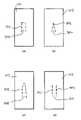
図1は、エアロゾル発生装置100と外部スリーブ120とを備えるエアロゾル発生システム10の斜視図を示す。エアロゾル発生装置100は、エアロゾル形成基体を含むエアロゾル形成物品を加熱するために構成されている。エアロゾル発生装置100は、装置ハウジング102と、図1では見えない複数の内部構成要素とを備える。装置ハウジング102は、外部表面103を有し、また内部空間104を包囲する。複数の内部構成要素は内部空間104内に包含されている。装置ハウジング102は管状であり、また金属の単体から形成されている。装置ハウジング102の外部表面103内に、複数の曲げることができる部分が形成されていて、この部分は、内部構成要素のうちの一つと相互作用するために、内部空間104の中に、もしくはこれに向かって曲げられている、または曲げることができる。各曲げることができる部分は、装置ハウジング102の外部表面103における切り込みによって画定されたタブ106、107、および108を備える。各タブ106、107、および108は、内部構成要素のうちの一つと相互作用する。 FIG. 1 shows a perspective view of an aerosol-generating
タブ106および107は固定要素である。各固定要素は、外部表面103を通して切り込みを入れることによってタブを画定し、次いでそのタブを内部空間104に向かって偏向させることによって形成されている。固定要素106、107は、内部構成要素を係合することによって内部構成要素と相互作用する。この係合は、装置ハウジング102に対して、それぞれの内部構成要素を定位置に保持する。
タブ108は、レバーの形態のユーザーインターフェース要素である。レバー108は、装置ハウジング102の中に切り込み入れることによってタブを形成し、そのタブが装置ハウジングの内部空間に入るように、タブを装置ハウジングの内部空間に向かって曲げることによって形成されている。レバー108は、ユーザーによって操作された時、装置ハウジングの内部空間の中にさらに偏向可能である。レバーは偏向された時に、内部構成要素と相互作用する。
装置ハウジング102は内部構成要素を安全に収容し、内部構成要素を損傷から保護するだけでなく、LEDなどの任意のさらなるユーザーインターフェース要素を支持する。切り込みを入れて、そしてその後にタブを偏向または曲げることによって、外部表面103内にタブを形成することは、安価であり、かつ単純である。装置ハウジング102は、いかなる外部スリーブも必要とすることなく、機能的に動作可能である。しかしながら、切り抜きタブを有する装置ハウジング102は、見た目が良くない、または保持するのに心地よくない。
エアロゾル発生装置100上に外部スリーブ120を提供することによって、エアロゾル発生装置を審美的に許容可能なものにすることができる。図1に示す実施形態において、外部スリーブ120は、装置ハウジングの外部表面103全体を取り外し可能に覆うように構成されている。しかしながら、これは必要とされない場合がある。エアロゾル発生装置100は、外部スリーブ120が、あらゆるタブが覆われるように外部表面103を十分に覆う場合、審美的に許容可能である場合がある。装置ハウジング102の一部の部分は、許容可能な外観および感触を有する場合がある。 By providing an
外部スリーブ120は、耐久性と可撓性の両方であるシリコーンから作製されていて、かつ外部スリーブが篏合されている時、スリーブと装置との間に緊密な嵌合があり、かつ外部スリーブが装置ハウジングに対して簡単に移動しないように、エアロゾル発生装置100の形状と一致するように成形されている。外部スリーブは、外部スリーブと装置ハウジングの間の摩擦によって定位置に保持されている。 The
外部スリーブ120はインターフェース部分122を備える。外部スリーブ120がエアロゾル発生装置100を覆う時、インターフェース部分122はレバー108を覆う。インターフェース部分122を押す装置のユーザーは、装置ハウジング102の内部空間104に向かってレバー108を偏向する。インターフェース部分122は、外部スリーブ120の表面内に形成された隆起したリング124によって画定されている。隆起したリング124は、外部スリーブ120によって覆われた、レバー108の場所に関する装置のユーザーに対する指標である。
上述の通り、外部スリーブ120を使用してエアロゾル発生装置100を覆うことは、許容可能な外観および感触を有するエアロゾル発生装置100を結果としてもたらす。エアロゾル発生装置100の外観は、外部スリーブ120の外観に依存する。特定の外観を有するカスタマイズされた外部スリーブ120が提供されてもよい。第二の外部スリーブを用いて第一の外部スリーブを取り外し、かつ交換することによって、エアロゾル発生装置100の外観を変更することができ、それ故にエアロゾル発生装置の継続的なカスタマイズを可能にする。これは図2で例示されている。 As described above, using the
図2は、図1に関連して記載の通りのエアロゾル発生装置100と、第一および第二の外部スリーブ202、212とを備えるキットの斜視図である。第一および第二の外部スリーブ202、212は、異なる外観を有することを除いて、互いに同一であり、かつ上述の外部スリーブ120と同一である。外部スリーブ202は、第一のロゴ204を備え、かつ単一の色である。外部スリーブ212は、第二のロゴ214を備え、かつ異なる二つの交互の色からなる縞状のパターンを有する。従って、外部スリーブ202は、外部スリーブ212とは異なる外観を有する。外部スリーブ202の代わりに外部スリーブ212(またはその逆も可)でエアロゾル発生装置100を覆うことは、エアロゾル発生装置100の外観を変えることになる。これはエアロゾル発生装置100のカスタマイズを可能にする。 FIG. 2 is a perspective view of a kit comprising an
当然のことながら、図2に示す外部スリーブ202および212は例示である。外部スリーブは、エアロゾル発生装置に所望の外観を与えるように、任意の視覚化情報、書き込み、またはその他のブランディングを備えてもよい。さらに、第一および第二のロゴ204および214は、異なるスリーブが異なるブランディングを含んでもよいことを実証する単なるプレースホルダーであり、また外部スリーブに含まれる実際のブランディングを表していないことは明確である。 Of course, the
図3は、エアロゾル発生物品302が受容されている、エアロゾル発生装置100の断面概略図である。図3は、装置ハウジング102内に包含された複数の内部構成要素を示す。 FIG. 3 is a schematic cross-sectional view of aerosol-generating
エアロゾル発生装置100は、受容部分304を備える。受容部分304は開口部310を備え、この開口部を通してエアロゾル発生物品302が挿入および取り外されうる。受容部分はまた、インダクタコイル312を備える加熱組立品を備える。インダクタコイル312は、受容部分304の長軸方向軸に対応する磁気軸を有するらせん状のインダクタコイルである(図3の破線を参照のこと)。エアロゾル発生装置100はまた、例えば再充電可能電池などの電源306と、例えば回路を有するプリント基板などの制御回路308とを備える。制御回路308とインダクタコイル312の両方は、電源306から電力を受信する。
エアロゾル形成物品302は、エアロゾル形成物品302が受容部分304内に受容されている時に、インダクタコイル312によって誘導加熱可能であるように、エアロゾル発生基体と、エアロゾル発生物品302内に配設された導電性サセプタ素子303とを含む。エアロゾル形成基体は、加熱に伴いエアロゾル形成基体から放出される揮発性のたばこ風味化合物を含むたばこ含有材料である。エアロゾル形成基体はまた、高密度の安定したエアロゾルの形成を容易にするグリセリンまたはプロピレングリコールなどのエアロゾル形成体を含む。 Aerosol-forming
エアロゾル発生装置100の動作は、制御回路308によって制御される。これは加熱サイクルを開始することを含み、これによって制御回路308は、制御回路308内に保存された所定の加熱プロファイルに従って、インダクタコイル312への電力の供給を制御する。 The operation of
制御回路308は、DC電源である電源306に接続されたDC/ACインバータを備える。DC/ACインバータは、トランジスタスイッチ、トランジスタスイッチ駆動回路、およびLC負荷ネットワークを含む、クラスE電力増幅器を含む。クラスE電力増幅器は一般に周知であり、例えば The American Radio Relay League (ARRL)(米国コネティカット州ニューイントン)の隔月雑誌『QEX』2001年1月/2月号の9~20ページに掲載された、Nathan O. Sokal著の論文「Class-E RF Power Amplifiers」に詳細に説明されている。従って、高周波電流をインダクタコイル312に供給することができる。変化する磁界は、高周波電流の結果として、インダクタによって発生される。これは、導電性サセプタ素子303内に変化する電流を誘導し、結果としてサセプタ素子303の加熱をもたらす。加熱されたサセプタ素子303はエアロゾルを形成するのに十分な温度までエアロゾル発生物品302のエアロゾル形成基体を加熱する。次にエアロゾルは、装置のユーザーによって吸入されるために、エアロゾル発生物品302を通して下流に引き出されることができる。
受信受容部分304は、インダクタコイル312を包囲する電磁シールド(図3に図示せず)を含む磁束集中器をさらに備える。磁束集中器は、インダクタコイル312によって発生された変動磁界を、受容部分304の中心に向かって(すなわち、受容部分304内に受容されたエアロゾル形成物品302に向かって)ゆがめる。これは受容部分304内の磁界を集中させ、それによってインダクタコイル312を通過する所与のレベルの電力に対するサセプタ素子303における発熱のレベルを増加させる。磁束集中器は管状であり、またその長軸方向軸に沿って延びる、インダクタコイルを包囲する。磁束集中器はフェライトから作製されている。電磁シールドは、装置の隣接する導電性部品(例えば金属装置ハウジング)の望ましくない加熱、またはエアロゾル発生装置100の外部の隣接する導電性アイテムの望ましくない加熱を低減する。インダクタコイル312の磁界を集中させること、および望ましくない加熱および損失を低減させることは、エアロゾル発生装置100の効率を増加させる。 Receive receiving
図4は、複数の内部構成要素と外部表面103を有する装置ハウジング102とを示す、エアロゾル発生装置100の分解組立斜視図である。主フレーム402には電源306および制御回路308がある。受容部分304は、コイル巻型404と、磁束集中器406(上述の通り)と、封入スリーブ408との組立品であり、その各々は他方の中に連続的に嵌合している。封入スリーブは、磁束集中器を定位置に保持するための保護外層である。コイル巻型404はインダクタコイル312を含む。コイル巻型404は、エアロゾル発生物品302が受容されている開口部310を画定する。エアロゾル発生装置100が組み立てられる時、主フレーム402は、装置ハウジング102の内部空間104の中に挿入され、その後、主フレーム402に当接する組み立てられた受容部分304が続く。端部410は、両端にて装置ハウジング102の中に押し込まれる。 FIG. 4 is an exploded perspective view of
装置ハウジング102において形成されたレバー108は、主フレーム402が装置ハウジング102の中に挿入されている時、制御回路308と接触している。レバー108の偏向は制御回路308によって検出される。次に制御回路は前述の加熱サイクルを開始する。 A
固定手段106は電源306と接触していて、固定手段107は受容部分304と接触している。これは、装置ハウジングに対する内部構成要素の移動を防止する。 The fixing means 106 are in contact with the
図5は装置ハウジング102の一部分の平面概略図であり、タブを形成することができる領域を画定する装置ハウジング102における切り込みの実施形態を示す。切り込みは破線502によって示されている。各実施形態における切り込み502によって画定された領域は、異なる形状を有する。これらの領域から形成されたタブが、異なる形状を有することになることは、当業者によってよく理解されるであろう。 FIG. 5 is a top schematic view of a portion of
図5(a)は、切り込み502が、装置ハウジングにおいて三つの側面上で領域504を画定する一実施形態を示す。領域504の第四の側面は切り込まれていない。領域504の一方の端は切り込みによって包囲されていて、本明細書において自由端と呼ばれる。もう一方の端は切り込まれていなく、本明細書において固定端と呼ばれる。 FIG. 5(a) shows an embodiment in which
自由端が固定端よりも低くなり、かつ自由端が内部構成要素と相互作用してこれを定位置に保持するように、固定要素は、領域504が装置ハウジングの内部空間に向かって偏向されている場合に形成されている。 The fixed element is biased in
領域504は装置ハウジング102の内部空間104の中に偏向可能であるため、ユーザーインターフェース要素が形成されている。一部の実施形態において、ユーザーインターフェース要素は、中立位置にある装置ハウジングの内部空間の中に、またはそれから離れるように曲げられている。しかしながら、これは必要とはされない。ユーザーインターフェース要素はレバーであり、そのためユーザーが押す自由端により近いほど、レバーを偏向させるために必要とされる力が小さくなる。
図5(b)および図5(c)は、領域506および508が、全側面上の切り込みによって画定された自由端、および固定端を有する、類似の実施形態を示す。異なる実施形態の切り込みは異なる形状を有し、そのため切り込みによって画定された領域は、異なる形状を有する。 Figures 5(b) and 5(c) show a similar embodiment in which
図5(d)に示す実施形態は、互いに隣接し、かつ実質的に等しい長さの二つの平行な切り込みから形成されているという点で、図5(a)~図5(c)の実施形態とは異なる。これらの二つの切り込みの間に画定された領域510は、自由端を有しず、むしろ二つの固定端を有する。 The embodiment shown in FIG. 5(d) is an implementation of FIGS. 5(a)-5(c) in that it is formed from two parallel cuts adjacent to each other and of substantially equal length. different from the form. The
図5(d)のタブは、第一の固定端から第二の固定端に画定された軸を有する。タブ軸は好ましくは、装置ハウジングの凸状の外表面に従う。これは、タブを延伸させる必要なく、タブが内部空間の中に押されることを可能にする。 The tab of FIG. 5(d) has an axis defined from a first fixed end to a second fixed end. The tab axis preferably follows the convex outer surface of the device housing. This allows the tab to be pushed into the interior space without having to stretch the tab.
固定要素は、領域510が装置ハウジング102の内部空間104に向かって偏向されている場合に形成されている。領域510の中央部分は内部構成要素と相互作用する。 A locking element is formed when the
図3を再び参照すると、エアロゾル発生装置は、装置ハウジングにおける切り込みから形成された、かつ内部構成要素と相互作用する複数の固定要素106、107、336、337を備える。エアロゾル発生装置はまた、制御回路308と相互作用するレバー108を備える。 Referring again to Figure 3, the aerosol generating device comprises a plurality of securing
固定要素106、107、336、337は、図5(d)に示す通りの装置ハウジング102における切り込みから形成されている。固定要素106および336は、電源306と相互作用するように偏向されている。固定要素107および337は、受容部分304と相互作用するように偏向されている。電源306および受容部分304との相互作用は、固定要素が摩擦接触するように偏向されていて、そのため装置ハウジングに対して電源および受容部分を定位置に保持することである。図3に示す実施形態において、固定要素は、それぞれの構成要素における溝の中に偏向されている。これは、構成要素を定位置に保持するための固定要素の信頼性を改善するが、必要とされる特徴ではない。固定要素と内部構成要素の間の摩擦接触は十分である。さらに、図3に示す実施形態において、電源306および受容部分304は各々、各構成要素の対向する側面上の二つの固定手段によって定位置に保持されている。この場合も、これは必要とされる特徴ではない。エアロゾル発生装置の特定の設計に応じて、任意の数の内部構成要素と接触している任意の数の固定手段があってもよい。 The fixing
レバー108は、図5(a)に示す実施形態による装置ハウジング102における切り込みから形成されている。レバー108は、制御回路308の一部を形成するスイッチ340に近接近するように、装置ハウジング102の内部空間に向かって曲げられている。レバー108は偏向可能である。レバー108の偏向は、スイッチ340によって感知されることができる。偏向が感知された時、制御回路308はエアロゾル発生装置の動作を開始するように構成されている。例えば、加熱サイクルを開始することによって、これによって制御回路308は、制御回路308内に保存された所定の加熱プロファイルに従って、インダクタ312への電力の供給を制御する。
図3に示す実施形態は、固定要素とユーザーインターフェース要素の両方を含む。しかしながら、エアロゾル発生装置は、固定要素またはユーザーインターフェース要素のみを備えてもよい。例えば、エアロゾル発生装置は、マイクロフォンの形態の吸煙センサーを備えてもよい。こうした一実施形態において、エアロゾル発生装置100内に受容されたエアロゾル発生物品302をユーザーが吸煙することの結果として、マイクロフォンが装置を通る気流を検出する時に、装置の動作が開始されてもよいため、ユーザーインターフェース要素は必要とされない場合がある。こうした一実施形態において、少なくとも一つの固定要素があってもよく、またユーザーインターフェース要素がなくてもよい。別の実施形態において、複数の内部構成要素は、エアロゾル発生装置100の中に挿入された端部410によって、装置ハウジング102のいずれかの端にて定位置に保持されることのみが必要である。従って、タブによって形成された固定要素は必要ない場合がある。 The embodiment shown in FIG. 3 includes both fixed elements and user interface elements. However, the aerosol-generating device may comprise only fixed elements or user interface elements. For example, the aerosol generator may include a smoke sensor in the form of a microphone. In one such embodiment, operation of the device may be initiated when a microphone detects airflow through the device as a result of a user puffing on an aerosol-generating
外部スリーブ120とレバー108の間の接触、特にインターフェース部分122とレバー108の間の接触が図6に示されている。図6は、レバー108を覆う外部スリーブ120の一部分の三つの異なる実施形態を拡大断面として示す。 The contact between
図6(a)は、インターフェース部分122の第一の実施形態を示す。この実施形態において、インターフェース部分122は、外部スリーブの表面の隆起した特徴の形態のマーキングによって画定されている。隆起した特徴は、外部スリーブ120の表面における隆起したリング124である。隆起したリング124は、レバー108の場所に関する装置のユーザーに対する指標の役割を果たす。ユーザーがインターフェース部分122を押し下げる時、可撓性のシリコーンで作製された外部スリーブは、レバー108に向かって曲がる。レバー108と接触するとレバー108は、エアロゾル発生装置100の内部空間104に向かって偏向される。 FIG. 6(a) shows a first embodiment of the
図6(b)はインターフェース部分122の第二の実施形態を示す。この実施形態において、外部スリーブ120のインターフェース部分は、外部スリーブ120の残りの部分と比較して増大した厚さ602の領域を備える。図6(b)に示す通り、増大した厚さ602は、レバー108と接触している外部スリーブ120の側面上にある。これは、レバー108を偏向する前に、インターフェース部分122が移動する必要のある距離を低減し、そのためレバー108を偏向させるためにインターフェース部分122を押す時に、ユーザーによって必要とされる力がより少ない。 FIG. 6(b) shows a second embodiment of the
図6(c)は、インターフェース部分122の第三の実施形態を示す。この実施形態において、インターフェース部分122は、外部スリーブにおけるへこみ604によって画定されている。へこみ604はリング形状を有する。へこみ604は、外部スリーブ120の残りの部分と比較して減少した厚さの領域であり、そのため外部スリーブ120の残りの部分と比較して増大した可撓性を有する。これは、インターフェース部分122がレバー108を偏向するように、外部スリーブ120を曲げるために必要とされる力の量を低減する。図6(c)に示す実施形態において、へこみ604は外部スリーブの両側にある。しかし当然のことながら、へこみ604は一方の側上のみにあってもよい。 FIG. 6( c ) shows a third embodiment of
図6(a)~図6(c)の特徴は組み合わせることができる。例えば、図6(b)に示す実施形態はまた、図6(a)に示す隆起したリング124、または図6(c)に示すへこみ604を備えてもよい。 The features of FIGS. 6(a)-6(c) can be combined. For example, the embodiment shown in Figure 6(b) may also include a raised
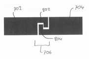
図7は、接続部706にて互いに接続された第一の部品702および第二の部品704を備える外部スリーブ120の一実施形態の斜視図である。インターフェース部分122は、第一の部品702の一部を形成する。接続部706は、図8において拡大断面として示されている。接続部706はスナップ嵌め接続である。第一の部品702は、溝802を備えるメス部品である。第二の部品704は、リップまたはリブ804を備えるオス部品である。応力がかかっていない状態において、リップ804と溝802は互いに嵌合しない。しかしながら、外部スリーブ120は弾性特性を有し、そのため力が加えられた時、リップ804と溝802の一方または両方が曲げられ、第一の部品および第二の部品は互いに嵌合されることができる。接合動作後、リップ804および溝802は、応力がかかっていない状態に戻り、取り外し可能な(その上、弾性の)接続を形成する。 FIG. 7 is a perspective view of one embodiment of
図9は、図1に示すエアロゾル発生システムを製造する方法を表す流れ図である。 FIG. 9 is a flow diagram representing a method of manufacturing the aerosol generating system shown in FIG.
まず、工程900において、装置ハウジング102が提供されている。前述の通り、装置ハウジング102は管状であり、また内部空間を包囲する。装置ハウジング102は金属で作製されている。 First, in step 900,
工程902において、複数の内部構成要素は、装置ハウジング102の内部空間104内に位置付けられている。この工程の前に、内部構成要素は組み立てられる必要がある。電源306と制御回路308の両方は、主フレーム402にある。受容部分312は、コイル巻型404から組み立てられていて、磁束集中器406の中に挿入されていて、これはその後、封入管408の中に挿入される。組み立てられた受容部分312は主フレーム402に当接し、主フレーム402に機械的に係合されている。この機械的係合は、主フレーム402の電源306および制御回路308が受容部分412と電気連通するように、電気的接続を備える。 At step 902 , a plurality of internal components are positioned within
工程904において、装置ハウジング102の外部表面103を通して切り込みを入れるために十分な力を用いて、切り込みツールを外部表面103の中に押すことによって、装置ハウジングの外部表面103において切り込みが作られている。装置ハウジングにおける切り込みは、外部ハウジングの曲げられた部分または曲げることができる部分であるタブを画定する。任意の数のタブが、外表面103に切り込みを入れることによって画定されてもよい。タブは、使用される切り込みツールに応じて、同時にまたは連続的に画定されてもよい。 At step 904 , a notch is made in the
製造方法の一部の実施形態において、複数の内部構成要素は、装置ハウジング102の外部表面103に切り込みが作られた後に、装置ハウジング102の内部空間内に位置付けられてもよい。こうした実施形態において、工程902は工程904の後に生じることになる。 In some embodiments of the method of manufacture, multiple internal components may be positioned within the interior space of
工程906において、タブは、プレス加工工具を使用して、装置ハウジングの内部に、またはそれから離れるように曲げられている、または偏向されている。二つ以上のタブが工程904で画定されている場合、任意の数のこれらのタブは曲げられてもよく、または偏向されてもよい。タブが、装置ハウジング102内に位置付けられた内部構成要素と係合するまで、プレス加工を使用して装置ハウジングの内部空間に向かってタブが偏向される時に、固定要素が形成される。タブが、装置ハウジング内に位置付けられた内部構成要素と近接近してユーザーインターフェース要素を形成するまで、プレスダイ工具を使用して装置ハウジングの内部空間104に向かってタブが曲げられる時に、ユーザーインターフェース要素が形成される。レバー108は、このようにして形成されたこうしたユーザーインターフェース要素の例である。別の方法として、または追加的に、ユーザーインターフェース要素は、タブを装置ハウジングの内部から離れるように曲げることによって形成されることができる。 At step 906, the tab is bent or deflected into or away from the device housing using a stamping tool. If more than one tab is defined in step 904, any number of these tabs may be bent or deflected. A locking element is formed when the tab is deflected toward the interior space of the device housing using a stamping until the tab engages an internal component located within the
製造プロセスの工程906は随意である。工程904で画定されたタブを曲げる、または偏向させることは、一部のユーザーインターフェース要素にとって必要とされない。ユーザーインターフェース要素は、内部空間に向かって偏向可能なタブであってもよい。タブは切り込まれると偏向可能になる。ユーザーインターフェース要素を形成するためにタブを曲げることは要件ではない。こうしたユーザーインターフェース要素の場合、工程906は実施されず、製造プロセスは工程904から工程908に飛ぶ。これは図9の破線の矢印によって示されている。 Step 906 of the manufacturing process is optional. Bending or deflecting the tabs defined in step 904 is not required for some user interface elements. The user interface element may be a tab that is deflectable toward the interior space. The tabs become deflectable when cut. Bending the tab to form a user interface element is not a requirement. For such user interface elements, step 906 is not performed and the manufacturing process jumps from step 904 to step 908. This is indicated by the dashed arrow in FIG.
工程908において、外部スリーブ120が提供されている。外部スリーブ120はシリコーンから成形されている。エアロゾル発生装置100がユーザーインターフェース要素を備える実施形態において、成形された外部スリーブはインターフェース領域122を備える。このインターフェース領域122は、外部スリーブへと成形されている。外部スリーブ120は、装置ハウジング100に切り込まれたタブを覆うように、装置ハウジングに嵌合されている。一部の実施形態において、工程908と工程910のうちのいずれかまたは両方は、工程900~906で概説されたプロセスとは別個のプロセスの一部を形成する。例えば、外部スリーブ120の装置ハウジングへの嵌合は、装置および外部スリーブ120を別々に購入した後、装置のユーザーによって実施されてもよい。嵌合は、特化した工具を必要とする場合がある。これらの場合において、装置のユーザーは、特化した工具を使用して外部スリーブを嵌合するまたは取り外す販売店に、外部スリーブ120および装置を持ち込んでもよい。 At step 908, an
外部スリーブ120は、視覚化情報、書き込み、またはブランディングを含む。このうちの一部は、外部スリーブ120を成形する時点で含まれる。例えば、外部スリーブを成形するために、特定の色を有するシリコーンが使用される。しかしながら典型的に、書き込みおよびブランディングなどの特徴は、外部スリーブの後加工に含まれなければならない。後加工のこうした方法は当業界で周知であり、例えば印刷を含む。
一部の実施形態において、外部スリーブ120は単体として成形されている。しかしながら、他の実施形態において、外部スリーブ120は二つの部品から成り、これらの部品はスナップ嵌め接続を使用して接続可能である。こうした場合において、これらの部品は、外部スリーブ120を成形する時に形成される相互の溝を備える。 In some embodiments,
Claims (15)
Translated fromJapanese前記エアロゾル発生装置が、
装置ハウジングと、
前記装置ハウジングによって包囲された内部空間内に包含された複数の内部構成要素と、を備え、
前記装置ハウジングが、外部表面と、前記内部構成要素のうちの一つと相互作用するために曲げられた、少なくとも一つの曲げられた部分とを備え、
前記外部スリーブが、前記少なくとも一つの曲げられた部分を覆う、エアロゾル発生システム。An aerosol-generating system comprising an aerosol-generating device for heating an aerosol-forming substrate and an outer sleeve, comprising:
The aerosol generator is
a device housing;
a plurality of internal components contained within an interior space enclosed by the device housing;
said device housing having an exterior surface and at least one bent portion bent to interact with one of said internal components;
The aerosol generating system, wherein the outer sleeve covers the at least one bent portion.
前記エアロゾル発生装置が、
装置ハウジングと、
前記装置ハウジングによって包囲された内部空間内に包含された複数の内部構成要素と、を備え、
前記装置ハウジングが、材料の単体から形成されていて、かつ外部表面と、前記内部構成要素のうちの一つと相互作用するために曲げられた、少なくとも一つの曲げられた部分とを備え、
前記少なくとも一つの外部スリーブが、前記少なくとも一つの曲げられた部分を取り外し可能に覆うように構成されている、キット。A kit comprising an aerosol generator for heating an aerosol-forming substrate and at least one outer sleeve, comprising:
The aerosol generator is
a device housing;
a plurality of internal components contained within an interior space enclosed by the device housing;
said device housing being formed from a unitary piece of material and comprising an exterior surface and at least one bent portion bent to interact with one of said internal components;
The kit, wherein the at least one outer sleeve is configured to removably cover the at least one bent portion.
内部空間内に複数の内部構成要素を包含するための装置ハウジングを提供する工程であって、前記装置ハウジングが外部表面を備える、提供する工程と、
前記内部構成要素のうちの一つと相互作用するために、前記内部空間に向かって曲げられた、少なくとも一つの曲げられた部分を前記装置ハウジング内に提供する工程と、
前記少なくとも一つの曲げられた部分を取り外し可能に覆うための外部スリーブを提供する工程と、を含む、方法。A method of manufacturing an aerosol generating system, comprising:
providing a device housing for containing a plurality of internal components within an interior space, the device housing comprising an exterior surface;
providing at least one bent portion within the device housing bent toward the interior space for interacting with one of the internal components;
providing an outer sleeve for removably covering said at least one bent portion.
前記外部スリーブを前記装置ハウジングに嵌合する工程と、をさらに含む、請求項14に記載のエアロゾル発生システムの製造方法。deflecting the at least one bent portion into the interior space to interact with one of the components;
15. The method of claim 14, further comprising fitting the outer sleeve to the device housing.
Applications Claiming Priority (3)
| Application Number | Priority Date | Filing Date | Title |
|---|---|---|---|
| EP19175003.3 | 2019-05-16 | ||
| EP19175003 | 2019-05-16 | ||
| PCT/EP2020/063184WO2020229465A1 (en) | 2019-05-16 | 2020-05-12 | Device assembly method and device manufactured according to such method |
Publications (3)
| Publication Number | Publication Date |
|---|---|
| JP2022534649Atrue JP2022534649A (en) | 2022-08-03 |
| JPWO2020229465A5 JPWO2020229465A5 (en) | 2023-05-19 |
| JP7569332B2 JP7569332B2 (en) | 2024-10-17 |
Family
ID=66589384
Family Applications (1)
| Application Number | Title | Priority Date | Filing Date |
|---|---|---|---|
| JP2021561797AActiveJP7569332B2 (en) | 2019-05-16 | 2020-05-12 | DEVICE ASSEMBLY METHOD AND DEVICES MADE ACCORDING TO SUCH METHOD - Patent application |
Country Status (6)
| Country | Link |
|---|---|
| US (1) | US12082612B2 (en) |
| EP (1) | EP3968799B1 (en) |
| JP (1) | JP7569332B2 (en) |
| KR (1) | KR20220008836A (en) |
| CN (1) | CN113710113B (en) |
| WO (1) | WO2020229465A1 (en) |
Families Citing this family (5)
| Publication number | Priority date | Publication date | Assignee | Title |
|---|---|---|---|---|
| US10750787B2 (en) | 2018-01-03 | 2020-08-25 | Cqens Technologies Inc. | Heat-not-burn device and method |
| US12201154B2 (en) | 2018-01-03 | 2025-01-21 | Cqens Technologies Inc. | Heat-not-burn device and method |
| JP7657738B2 (en) | 2019-06-05 | 2025-04-07 | フィリップ・モーリス・プロダクツ・ソシエテ・アノニム | Aerosol generating device having a thermally conductive assembly |
| IL288436B2 (en) | 2019-06-05 | 2025-05-01 | Philip Morris Products Sa | Frame for an aerosol-generating device and method of forming a frame |
| US20240381946A1 (en)* | 2021-07-15 | 2024-11-21 | Philip Morris Products S.A. | Aerosol-generating device with overmoulded button |
Citations (10)
| Publication number | Priority date | Publication date | Assignee | Title |
|---|---|---|---|---|
| DE19616917A1 (en)* | 1996-04-27 | 1997-10-30 | Rohde & Schwarz | Operating device for electric push-button switch |
| JP2013518577A (en)* | 2010-02-05 | 2013-05-23 | カインド・コンシューマー・リミテッド | Simulated smoking device |
| JP2014524313A (en)* | 2011-08-16 | 2014-09-22 | プルーム,インク. | Low temperature electron vaporization device and method |
| GB2519781A (en)* | 2013-10-30 | 2015-05-06 | British American Tobacco Co | An Inhaler |
| JP2016524777A (en)* | 2014-05-21 | 2016-08-18 | フィリップ・モーリス・プロダクツ・ソシエテ・アノニム | Induction heating device, aerosol delivery system with induction heating device, and method of operating the same |
| WO2017109868A1 (en)* | 2015-12-22 | 2017-06-29 | 日本たばこ産業株式会社 | Power supply assembly, non-combustion-type flavor inhaler, non-combustion-type flavor inhalation system |
| WO2018055381A1 (en)* | 2016-09-23 | 2018-03-29 | Nicoventures Holdings Limited | Electronic vapour provision system |
| JP2018532377A (en)* | 2015-09-18 | 2018-11-08 | フィリップ・モーリス・プロダクツ・ソシエテ・アノニム | Liquid for electronic vapor equipment |
| JP2019503677A (en)* | 2015-12-18 | 2019-02-14 | ジェイティー インターナショナル エス.エイ. | Personal vaporizer device |
| JP2019506894A (en)* | 2015-12-28 | 2019-03-14 | アール・エイ・アイ・ストラテジック・ホールディングス・インコーポレイテッド | Aerosol delivery device including housing and coupler |
Family Cites Families (10)
| Publication number | Priority date | Publication date | Assignee | Title |
|---|---|---|---|---|
| US5878752A (en)* | 1996-11-25 | 1999-03-09 | Philip Morris Incorporated | Method and apparatus for using, cleaning, and maintaining electrical heat sources and lighters useful in smoking systems and other apparatuses |
| EP2340729A1 (en)* | 2009-12-30 | 2011-07-06 | Philip Morris Products S.A. | An improved heater for an electrically heated aerosol generating system |
| HUE030009T2 (en)* | 2012-01-03 | 2017-04-28 | Philip Morris Products Sa | Aerosol-generating device and system |
| US10004259B2 (en) | 2012-06-28 | 2018-06-26 | Rai Strategic Holdings, Inc. | Reservoir and heater system for controllable delivery of multiple aerosolizable materials in an electronic smoking article |
| SG11201507442TA (en)* | 2013-03-15 | 2015-10-29 | Philip Morris Products Sa | An aerosol-generating system with a replacable mouthpiece cover |
| MX2015013513A (en)* | 2013-03-22 | 2016-10-26 | Altria Client Services Llc | Electronic smoking article. |
| DE202014011260U1 (en)* | 2013-12-23 | 2018-11-13 | Juul Labs Uk Holdco Limited | Systems for an evaporation device |
| MY184211A (en)* | 2014-08-21 | 2021-03-26 | Philip Morris Products Sa | Aerosol-generating device and system |
| GB201511358D0 (en) | 2015-06-29 | 2015-08-12 | Nicoventures Holdings Ltd | Electronic aerosol provision systems |
| PL3806583T3 (en) | 2016-08-31 | 2024-01-15 | Philip Morris Products S.A. | Aerosol generating device with inductor |
- 2020
- 2020-05-12JPJP2021561797Apatent/JP7569332B2/enactiveActive
- 2020-05-12USUS17/611,345patent/US12082612B2/enactiveActive
- 2020-05-12WOPCT/EP2020/063184patent/WO2020229465A1/ennot_activeCeased
- 2020-05-12EPEP20725703.1Apatent/EP3968799B1/enactiveActive
- 2020-05-12KRKR1020217038264Apatent/KR20220008836A/enactivePending
- 2020-05-12CNCN202080030565.8Apatent/CN113710113B/enactiveActive
Patent Citations (10)
| Publication number | Priority date | Publication date | Assignee | Title |
|---|---|---|---|---|
| DE19616917A1 (en)* | 1996-04-27 | 1997-10-30 | Rohde & Schwarz | Operating device for electric push-button switch |
| JP2013518577A (en)* | 2010-02-05 | 2013-05-23 | カインド・コンシューマー・リミテッド | Simulated smoking device |
| JP2014524313A (en)* | 2011-08-16 | 2014-09-22 | プルーム,インク. | Low temperature electron vaporization device and method |
| GB2519781A (en)* | 2013-10-30 | 2015-05-06 | British American Tobacco Co | An Inhaler |
| JP2016524777A (en)* | 2014-05-21 | 2016-08-18 | フィリップ・モーリス・プロダクツ・ソシエテ・アノニム | Induction heating device, aerosol delivery system with induction heating device, and method of operating the same |
| JP2018532377A (en)* | 2015-09-18 | 2018-11-08 | フィリップ・モーリス・プロダクツ・ソシエテ・アノニム | Liquid for electronic vapor equipment |
| JP2019503677A (en)* | 2015-12-18 | 2019-02-14 | ジェイティー インターナショナル エス.エイ. | Personal vaporizer device |
| WO2017109868A1 (en)* | 2015-12-22 | 2017-06-29 | 日本たばこ産業株式会社 | Power supply assembly, non-combustion-type flavor inhaler, non-combustion-type flavor inhalation system |
| JP2019506894A (en)* | 2015-12-28 | 2019-03-14 | アール・エイ・アイ・ストラテジック・ホールディングス・インコーポレイテッド | Aerosol delivery device including housing and coupler |
| WO2018055381A1 (en)* | 2016-09-23 | 2018-03-29 | Nicoventures Holdings Limited | Electronic vapour provision system |
Also Published As
| Publication number | Publication date |
|---|---|
| KR20220008836A (en) | 2022-01-21 |
| WO2020229465A1 (en) | 2020-11-19 |
| JP7569332B2 (en) | 2024-10-17 |
| EP3968799A1 (en) | 2022-03-23 |
| US12082612B2 (en) | 2024-09-10 |
| CN113710113B (en) | 2025-04-18 |
| CN113710113A (en) | 2021-11-26 |
| US20220225676A1 (en) | 2022-07-21 |
| EP3968799B1 (en) | 2023-07-05 |
Similar Documents
| Publication | Publication Date | Title |
|---|---|---|
| JP7569332B2 (en) | DEVICE ASSEMBLY METHOD AND DEVICES MADE ACCORDING TO SUCH METHOD - Patent application | |
| CN109414067B (en) | Apparatus for heating smokable material | |
| US20220408827A1 (en) | Aerosol-generating device with detachably insertable heating compartment | |
| KR102368912B1 (en) | Aerosol-generating device with modular induction heater | |
| RU2742806C1 (en) | Steam supply systems | |
| EP3179828B1 (en) | Cigarette heating device | |
| JP7668328B2 (en) | Aerosol generating consumables | |
| KR102726709B1 (en) | Aerosol generating device having an axially movable induction heater | |
| CN113853131B (en) | Frame for an aerosol generating device and method of forming the frame | |
| EP3664637A1 (en) | Aerosol-generating device with induction heater and movable components | |
| WO2015177253A1 (en) | Inductive heating device and system for aerosol generation | |
| JP7465352B2 (en) | Aerosol generating device with movable parts | |
| KR20220027844A (en) | Induction heating arrangement with annular channels | |
| US20230371603A1 (en) | Aerosol provision device heating system | |
| RU2816304C2 (en) | Aerosol generating system, aerosol generating system kit, and method of making aerosol generating system | |
| US20250049134A1 (en) | Aerosol provision device | |
| JP7746394B2 (en) | Apparatus for heating aerosolizable materials | |
| CN222217217U (en) | Heating assembly and aerosol generating device | |
| US20250295174A1 (en) | Aerosol provision device | |
| US20250057219A1 (en) | Mouth component for an aerosol provision device | |
| EP4062776B1 (en) | Atomization assembly | |
| RU2817586C2 (en) | Frame for aerosol-generating device (versions), method for making frame and aerosol-generating device | |
| HK40064999A (en) | Aerosol-generating device with detachably insertable heating compartment | |
| KR20220154464A (en) | Induction heating heater having double heaters |
Legal Events
| Date | Code | Title | Description |
|---|---|---|---|
| A521 | Request for written amendment filed | Free format text:JAPANESE INTERMEDIATE CODE: A523 Effective date:20230511 | |
| A621 | Written request for application examination | Free format text:JAPANESE INTERMEDIATE CODE: A621 Effective date:20230511 | |
| A977 | Report on retrieval | Free format text:JAPANESE INTERMEDIATE CODE: A971007 Effective date:20240530 | |
| A131 | Notification of reasons for refusal | Free format text:JAPANESE INTERMEDIATE CODE: A131 Effective date:20240603 | |
| A521 | Request for written amendment filed | Free format text:JAPANESE INTERMEDIATE CODE: A523 Effective date:20240805 | |
| TRDD | Decision of grant or rejection written | ||
| A01 | Written decision to grant a patent or to grant a registration (utility model) | Free format text:JAPANESE INTERMEDIATE CODE: A01 Effective date:20240905 | |
| A61 | First payment of annual fees (during grant procedure) | Free format text:JAPANESE INTERMEDIATE CODE: A61 Effective date:20241004 | |
| R150 | Certificate of patent or registration of utility model | Ref document number:7569332 Country of ref document:JP Free format text:JAPANESE INTERMEDIATE CODE: R150 |