JP2022532044A - How to display hotspot maps, devices, computer equipment and readable storage media - Google Patents
How to display hotspot maps, devices, computer equipment and readable storage mediaDownload PDFInfo
- Publication number
- JP2022532044A JP2022532044AJP2021564355AJP2021564355AJP2022532044AJP 2022532044 AJP2022532044 AJP 2022532044AJP 2021564355 AJP2021564355 AJP 2021564355AJP 2021564355 AJP2021564355 AJP 2021564355AJP 2022532044 AJP2022532044 AJP 2022532044A
- Authority
- JP
- Japan
- Prior art keywords
- hotspot
- map
- coordinate data
- gpu
- patch
- Prior art date
- Legal status (The legal status is an assumption and is not a legal conclusion. Google has not performed a legal analysis and makes no representation as to the accuracy of the status listed.)
- Granted
Links
Images


Classifications
- G—PHYSICS
- G06—COMPUTING OR CALCULATING; COUNTING
- G06T—IMAGE DATA PROCESSING OR GENERATION, IN GENERAL
- G06T15/00—3D [Three Dimensional] image rendering
- G06T15/005—General purpose rendering architectures
- G—PHYSICS
- G06—COMPUTING OR CALCULATING; COUNTING
- G06T—IMAGE DATA PROCESSING OR GENERATION, IN GENERAL
- G06T17/00—Three dimensional [3D] modelling, e.g. data description of 3D objects
- G06T17/20—Finite element generation, e.g. wire-frame surface description, tesselation
- A—HUMAN NECESSITIES
- A63—SPORTS; GAMES; AMUSEMENTS
- A63F—CARD, BOARD, OR ROULETTE GAMES; INDOOR GAMES USING SMALL MOVING PLAYING BODIES; VIDEO GAMES; GAMES NOT OTHERWISE PROVIDED FOR
- A63F13/00—Video games, i.e. games using an electronically generated display having two or more dimensions
- A63F13/50—Controlling the output signals based on the game progress
- A63F13/53—Controlling the output signals based on the game progress involving additional visual information provided to the game scene, e.g. by overlay to simulate a head-up display [HUD] or displaying a laser sight in a shooting game
- A63F13/537—Controlling the output signals based on the game progress involving additional visual information provided to the game scene, e.g. by overlay to simulate a head-up display [HUD] or displaying a laser sight in a shooting game using indicators, e.g. showing the condition of a game character on screen
- A63F13/5378—Controlling the output signals based on the game progress involving additional visual information provided to the game scene, e.g. by overlay to simulate a head-up display [HUD] or displaying a laser sight in a shooting game using indicators, e.g. showing the condition of a game character on screen for displaying an additional top view, e.g. radar screens or maps
- G—PHYSICS
- G06—COMPUTING OR CALCULATING; COUNTING
- G06T—IMAGE DATA PROCESSING OR GENERATION, IN GENERAL
- G06T1/00—General purpose image data processing
- G06T1/20—Processor architectures; Processor configuration, e.g. pipelining
- G—PHYSICS
- G06—COMPUTING OR CALCULATING; COUNTING
- G06T—IMAGE DATA PROCESSING OR GENERATION, IN GENERAL
- G06T15/00—3D [Three Dimensional] image rendering
- G06T15/04—Texture mapping
- G—PHYSICS
- G06—COMPUTING OR CALCULATING; COUNTING
- G06T—IMAGE DATA PROCESSING OR GENERATION, IN GENERAL
- G06T15/00—3D [Three Dimensional] image rendering
- G06T15/50—Lighting effects
- G06T15/60—Shadow generation
- G—PHYSICS
- G06—COMPUTING OR CALCULATING; COUNTING
- G06T—IMAGE DATA PROCESSING OR GENERATION, IN GENERAL
- G06T15/00—3D [Three Dimensional] image rendering
- G06T15/50—Lighting effects
- G06T15/80—Shading
- G—PHYSICS
- G06—COMPUTING OR CALCULATING; COUNTING
- G06T—IMAGE DATA PROCESSING OR GENERATION, IN GENERAL
- G06T17/00—Three dimensional [3D] modelling, e.g. data description of 3D objects
- G06T17/05—Geographic models
- G—PHYSICS
- G06—COMPUTING OR CALCULATING; COUNTING
- G06T—IMAGE DATA PROCESSING OR GENERATION, IN GENERAL
- G06T17/00—Three dimensional [3D] modelling, e.g. data description of 3D objects
- G06T17/10—Constructive solid geometry [CSG] using solid primitives, e.g. cylinders, cubes
- G—PHYSICS
- G06—COMPUTING OR CALCULATING; COUNTING
- G06T—IMAGE DATA PROCESSING OR GENERATION, IN GENERAL
- G06T19/00—Manipulating 3D models or images for computer graphics
- G06T19/20—Editing of 3D images, e.g. changing shapes or colours, aligning objects or positioning parts
- G—PHYSICS
- G06—COMPUTING OR CALCULATING; COUNTING
- G06T—IMAGE DATA PROCESSING OR GENERATION, IN GENERAL
- G06T7/00—Image analysis
- G06T7/70—Determining position or orientation of objects or cameras
- A—HUMAN NECESSITIES
- A63—SPORTS; GAMES; AMUSEMENTS
- A63F—CARD, BOARD, OR ROULETTE GAMES; INDOOR GAMES USING SMALL MOVING PLAYING BODIES; VIDEO GAMES; GAMES NOT OTHERWISE PROVIDED FOR
- A63F2300/00—Features of games using an electronically generated display having two or more dimensions, e.g. on a television screen, showing representations related to the game
- A63F2300/30—Features of games using an electronically generated display having two or more dimensions, e.g. on a television screen, showing representations related to the game characterized by output arrangements for receiving control signals generated by the game device
- A63F2300/303—Features of games using an electronically generated display having two or more dimensions, e.g. on a television screen, showing representations related to the game characterized by output arrangements for receiving control signals generated by the game device for displaying additional data, e.g. simulating a Head Up Display
- A63F2300/307—Features of games using an electronically generated display having two or more dimensions, e.g. on a television screen, showing representations related to the game characterized by output arrangements for receiving control signals generated by the game device for displaying additional data, e.g. simulating a Head Up Display for displaying an additional window with a view from the top of the game field, e.g. radar screen
- G—PHYSICS
- G06—COMPUTING OR CALCULATING; COUNTING
- G06T—IMAGE DATA PROCESSING OR GENERATION, IN GENERAL
- G06T2200/00—Indexing scheme for image data processing or generation, in general
- G06T2200/28—Indexing scheme for image data processing or generation, in general involving image processing hardware
- G—PHYSICS
- G06—COMPUTING OR CALCULATING; COUNTING
- G06T—IMAGE DATA PROCESSING OR GENERATION, IN GENERAL
- G06T2219/00—Indexing scheme for manipulating 3D models or images for computer graphics
- G06T2219/004—Annotating, labelling
- G—PHYSICS
- G06—COMPUTING OR CALCULATING; COUNTING
- G06T—IMAGE DATA PROCESSING OR GENERATION, IN GENERAL
- G06T2219/00—Indexing scheme for manipulating 3D models or images for computer graphics
- G06T2219/20—Indexing scheme for editing of 3D models
- G06T2219/2012—Colour editing, changing, or manipulating; Use of colour codes
Landscapes
- Engineering & Computer Science (AREA)
- Physics & Mathematics (AREA)
- Theoretical Computer Science (AREA)
- General Physics & Mathematics (AREA)
- Computer Graphics (AREA)
- Geometry (AREA)
- Software Systems (AREA)
- Multimedia (AREA)
- Radar, Positioning & Navigation (AREA)
- Optics & Photonics (AREA)
- Computer Vision & Pattern Recognition (AREA)
- General Engineering & Computer Science (AREA)
- Remote Sensing (AREA)
- Computer Hardware Design (AREA)
- Architecture (AREA)
- Image Generation (AREA)
- Instructional Devices (AREA)
Abstract
Translated fromJapanese
Description
Translated fromJapanese本願は、2020年2月18日に提出した出願番号が202010099511.9で、発明の名称が「ホットスポットマップの表示方法、装置、機器および読み取り可能な記憶媒体」である中国特許出願の優先権を主張し、その内容全体が引用により本明細書に組み込まれている。 This application is the priority of a Chinese patent application filed on February 18, 2020, with an application number of 2020109511.9 and the title of the invention being "Hotspot map display method, device, device and readable storage medium". And the entire content is incorporated herein by reference.
本願の実施例は、インターフェース表示分野に関し、特に、ホットスポットマップの表示方法、装置、コンピュータ機器および読み取り可能な記憶媒体に関する。 The embodiments of the present application relate to the field of interface display, in particular to hotspot map display methods, devices, computer equipment and readable storage media.
ホットスポットマップは、オブジェクトまたはイベントの分布状況、例えば、データの分布状況、仮想環境における仮想オブジェクトの分布状況、仮想オブジェクトの仮想環境における移動の分布状況等を表すためのものであり、例示的に、仮想環境に仮想オブジェクトが含まれ、仮想環境インターフェースにミニマップが表示されており、プレイヤは、仮想環境に対応するヒートマップを表示するようにミニマップを制御でき、ヒートマップによって仮想オブジェクトの仮想環境における分布状況を表す。 The hotspot map is for showing the distribution status of objects or events, for example, the distribution status of data, the distribution status of virtual objects in a virtual environment, the distribution status of movement of virtual objects in a virtual environment, and the like, and is exemplary. , The virtual environment contains virtual objects, the virtual environment interface displays the minimap, the player can control the minimap to display the heatmap corresponding to the virtual environment, and the heatmap allows the virtual object to be virtual. Represents the distribution in the environment.
関連技術では、ミニマップにおいてヒートマップをレンダリングする時に、先ず、仮想オブジェクトの仮想環境における座標を収集し、それぞれの仮想オブジェクトの座標にアクセスしてからヒートマップの円形減衰値を計算し、テクスチャデータを生成し、CPU(Central Processing Unit,中央処理装置)によってテクスチャデータをGPU(Graphics Processing Unit,グラフィックス・プロセッシング・ユニット)に送信してレンダリングを行う。 In a related technology, when rendering a heatmap in a minimap, it first collects the coordinates of the virtual objects in the virtual environment, accesses the coordinates of each virtual object, then calculates the circular decay value of the heatmap, and texture data. Is generated, and the texture data is transmitted to the GPU (Graphics Processing Unit) by the CPU (Central Processing Unit) to perform rendering.
しかしながら、上記ヒートマップのレンダリング中において、所望のホットスポットマップのテクスチャデータを生成するために、CPUは、煩雑な計算をしなければならず、負荷が大きくなり、端末の処理落ちが発生しやすい。 However, during the rendering of the heat map, in order to generate the texture data of the desired hotspot map, the CPU has to perform complicated calculations, the load becomes large, and the processing of the terminal is likely to be dropped. ..
本願の実施例は、CPUの計算リソースを他のプログラムロジックのために解放し、端末の処理速度を向上させることができるホットスポットマップの表示方法、装置、コンピュータ機器および読み取り可能な記憶媒体を提供する。前記技術手段を次に記載する。 The embodiments of the present application provide hotspot map display methods, devices, computer equipment and readable storage media that can free up CPU computational resources for other program logic and improve terminal processing speed. do. The technical means will be described below.
一側面において、ホットスポット位置の座標データを収集し、前記座標データをGPUに送信することと、
前記GPUによって、前記座標データに対応するポイントプリミティブ集合を、前記座標データに対応するパッチプリミティブからなるパッチプリミティブ集合に変換することであって、前記ホットスポットマップにおけるホットスポット領域が前記パッチプリミティブを組み合わせることによって生成される前記ことと、
前記GPUによって、前記パッチプリミティブ集合に対して色付けレンダリングを行うことで、前記ホットスポットマップを得ることと、
前記ホットスポット位置に対応する前記ホットスポットマップを表示することと、
を含むホットスポットマップの表示方法を提供する。In one aspect, collecting the coordinate data of the hotspot position and transmitting the coordinate data to the GPU,
The GPU converts a set of point primitives corresponding to the coordinate data into a set of patch primitives consisting of patch primitives corresponding to the coordinate data, wherein the hotspot area in the hotspot map combines the patch primitives. And the above generated by
By performing color rendering on the patch primitive set by the GPU, the hotspot map can be obtained.
Displaying the hotspot map corresponding to the hotspot position and
Provides a method of displaying a hotspot map including.
他の側面において、ホットスポット位置の座標データを収集し、前記座標データをGPUに送信するための取得モジュールと、
前記GPUによって、前記座標データに対応するポイントプリミティブ集合を、前記座標データに対応するパッチプリミティブからなるパッチプリミティブ集合に変換するための変換モジュールであって、前記ホットスポットマップにおけるホットスポット領域が前記パッチプリミティブを組み合わせることによって生成される前記変換モジュールと、
前記GPUによって、前記パッチプリミティブ集合に対して色付けレンダリングを行うことで、前記ホットスポットマップを得るためのレンダリングモジュールと、
前記ホットスポット位置に対応する前記ホットスポットマップを表示するための表示モジュールと、
を備えるホットスポットマップの表示装置を提供する。In another aspect, an acquisition module for collecting the coordinate data of the hotspot position and transmitting the coordinate data to the GPU,
It is a conversion module for converting a point primitive set corresponding to the coordinate data into a patch primitive set consisting of patch primitives corresponding to the coordinate data by the GPU, and the hotspot area in the hotspot map is the patch. The conversion module generated by combining the primitives and
A rendering module for obtaining the hotspot map by performing color rendering on the patch primitive set by the GPU.
A display module for displaying the hotspot map corresponding to the hotspot position,
A hotspot map display device is provided.
選択的な実施例において、前記取得モジュールは、前記GPUによって、前記パッチプリミティブ集合に対応するグレースケール画像を取得することにさらに用いられ、
前記レンダリングモジュールは、シェーダによって、前記グレースケール画像を色付けすることで、前記ホットスポット位置に対応するカラーホットスポットマップを得ることにさらに用いられる。In a selective embodiment, the acquisition module is further used by the GPU to acquire a grayscale image corresponding to the patch primitive set.
The rendering module is further used to obtain a color hotspot map corresponding to the hotspot location by coloring the grayscale image with a shader.
選択的な実施例において、前記取得モジュールは、前記GPUによって、前記パッチプリミティブ集合におけるパッチプリミティブに対して半透過処理を行うことで、前記パッチプリミティブ集合に対応する前記グレースケール画像を得ることにさらに用いられる。 In a selective embodiment, the acquisition module further performs translucency processing on the patch primitives in the patch primitive set by the GPU to obtain the grayscale image corresponding to the patch primitive set. Used.
選択的な実施例において、前記取得モジュールは、前記ホットスポットマップにおけるホットスポット状況と正相関する色配置を含む参照プリセットカラーテクスチャを取得することにさらに用いられ、
前記レンダリングモジュールは、前記シェーダによって、前記参照プリセットカラーテクスチャに応じて前記グレースケール画像を色付けすることで、前記ホットスポット位置に対応する前記カラーホットスポットマップを得ることにさらに用いられる。In a selective embodiment, the acquisition module is further used to acquire a reference preset color texture that includes a color arrangement that positively correlates with the hotspot situation in the hotspot map.
The rendering module is further used to obtain the color hotspot map corresponding to the hotspot location by coloring the grayscale image with the shader according to the reference preset color texture.
選択的な実施例において、前記ホットスポットマップは仮想環境における対象仮想オブジェクトの移動配置を示すためのものであり、
前記取得モジュールは、少なくとも1回の仮想対戦における前記対象仮想オブジェクトの移動座標を含む前記対象仮想オブジェクトの前記仮想環境における過去移動座標データを収集することにさらに用いられる。In a selective embodiment, the hotspot map is intended to show the movement and placement of target virtual objects in a virtual environment.
The acquisition module is further used to collect past movement coordinate data of the target virtual object in the virtual environment including the movement coordinates of the target virtual object in at least one virtual battle.
選択的な実施例において、前記取得モジュールは、所定のプリセット時間おきの前記対象仮想オブジェクトの前記仮想環境における位置情報を収集し、前記過去移動座標データを得ることにさらに用いられる。 In a selective embodiment, the acquisition module is further used to collect location information of the target virtual object in the virtual environment at predetermined preset times and to obtain past movement coordinate data.
選択的な実施例において、前記表示モジュールは、対象対戦に参加する仮想オブジェクトの前記仮想環境における移動ホットスポットマップをクエリするためのホットスポットマップクエリインターフェースであって、少なくとも1つの候補仮想オブジェクトを含む前記ホットスポットマップクエリインターフェースにさらに用いられ、
前記装置は、
前記ホットスポットマップクエリインターフェースにおいて、前記対象仮想オブジェクトの前記移動ホットスポットマップに対するクエリを示すための前記対象仮想オブジェクトに対する選択操作を受信するための受信モジュールをさらに備える。In a selective embodiment, the display module is a hotspot map query interface for querying a moving hotspot map of a virtual object participating in a target match in the virtual environment, and includes at least one candidate virtual object. Further used in the hotspot map query interface,
The device is
The hotspot map query interface further comprises a receiving module for receiving a selection operation on the target virtual object to indicate a query for the moving hotspot map of the target virtual object.
選択的な実施例において、前記表示モジュールは、前記仮想環境に対応するマップ表示領域において、前記ホットスポット位置に対応する前記ホットスポットマップを表示することにさらに用いられる。 In a selective embodiment, the display module is further used to display the hotspot map corresponding to the hotspot location in the map display area corresponding to the virtual environment.
他の側面において、プロセッサと、少なくとも一つのコマンド、少なくとも一つのプログラム、コードセットまたはコマンドセットが記憶されているメモリと、を備え、前記少なくとも一つのコマンド、前記少なくとも一つのプログラム、前記コードセットまたはコマンドセットは、前記プロセッサによりロードして実行されることで、上記の本願の実施例のいずれか一項に記載のホットスポットマップの表示方法を実現するコンピュータ機器を提供する。 In another aspect, it comprises a processor and a memory in which at least one command, at least one program, code set or command set is stored, said at least one command, said at least one program, said code set or The command set is loaded and executed by the processor to provide a computer device that realizes the method of displaying a hotspot map according to any one of the above embodiments of the present application.
他の側面において、プロセッサによりロードして実行されることで、上記の本願の実施例のいずれか一項に記載のホットスポットマップの表示方法を実現するコンピュータプログラムが少なくとも1つ記憶されている、コンピュータ読み取り可能な記憶媒体を提供する。 In another aspect, at least one computer program is stored that implements the method of displaying a hotspot map according to any one of the embodiments of the present application, loaded and executed by a processor. Provides a computer-readable storage medium.
他の側面において、コンピュータ読み取り可能な記憶媒体に記憶されたコンピュータコマンドを含むコンピュータプログラム製品またはコンピュータプログラムを提供する。コンピュータ機器のプロセッサは、コンピュータ読み取り可能な記憶媒体から該コンピュータコマンドを読み取り、該コンピュータコマンドを実行することによって、該コンピュータ機器に上記本願の実施例のいずれか一項に記載のホットスポットマップの表示方法を実行させる。 In another aspect, it provides a computer program product or computer program that includes computer commands stored in a computer-readable storage medium. The processor of the computer device reads the computer command from a computer-readable storage medium and executes the computer command to display the hotspot map according to any one of the embodiments of the present application on the computer device. Make the method run.
本願の実施例によって提供される技術手段は少なくとも次の有益な効果をもたらす。 The technical means provided by the embodiments of the present application have at least the following beneficial effects.
CPUによってホットスポット位置の座標データを確認してから、座標データに対応するポイントプリミティブをGPUに送信し、GPUによって座標データに対応するポイントプリミティブ集合を変換することで、対応するパッチプリミティブ集合を得、パッチプリミティブ集合に対して色付けレンダリングを行うことによって、ホットスポットマップを得て表示する。これによって、ホットスポットマップの計算レンダリング中において、ほとんどの演算をGPUが行うことによって、CPUの計算負担を軽減し、CPUの計算リソースを他のプログラムロジックのために解放する。 After confirming the coordinate data of the hotspot position by the CPU, the point primitive corresponding to the coordinate data is transmitted to the GPU, and the point primitive set corresponding to the coordinate data is converted by the GPU to obtain the corresponding patch primitive set. , A hotspot map is obtained and displayed by performing color rendering on the patch primitive set. This reduces the computational load on the CPU and frees the computational resources of the CPU for other program logic by having the GPU perform most of the computation during the computational rendering of the hotspot map.
本願の実施例における技術手段をより明確に説明するために、以下、実施例の説明に用いられる図面を簡単に説明するが、もちろん、次に記載される図面は本願のいくつかの実施例に過ぎず、当業者であれば、創造性のある労働を費やせずにこれらの図面により他の図面を得ることもできる。 In order to more clearly explain the technical means in the embodiments of the present application, the drawings used in the description of the embodiments will be briefly described below, but of course, the drawings described below are described in some embodiments of the present application. However, those skilled in the art can also obtain other drawings from these drawings without spending creative labor.
本願の目的、技術手段及び利点をより明確にするために、次に、図面を参照しながら本願の実施形態をさらに詳しく説明する。 In order to further clarify the objectives, technical means and advantages of the present application, the embodiments of the present application will be described in more detail with reference to the drawings.
先ず、本願の実施例に用いられる用語を簡単に説明する。 First, the terms used in the examples of the present application will be briefly described.
1)仮想環境
仮想環境とは、アプリケーションが端末で稼働する時に表示(または提供)される仮想環境である。該仮想環境は現実世界のシミュレーション環境であってもよいし、半シミュレーション半架空の環境であってもよいし、完全架空の環境であってもよい。仮想環境は2次元仮想環境、2.5次元仮想環境および3次元仮想環境のいずれか1つであってもよいが、本願において、これについて特に限定しない。下記実施例において、仮想環境が3次元仮想環境であることを例として説明する。1) Virtual environment A virtual environment is a virtual environment that is displayed (or provided) when an application runs on a terminal. The virtual environment may be a real-world simulation environment, a semi-simulation semi-fictitious environment, or a completely fictitious environment. The virtual environment may be any one of a two-dimensional virtual environment, a 2.5-dimensional virtual environment, and a three-dimensional virtual environment, but this is not particularly limited in the present application. In the following embodiment, the virtual environment will be described as an example of a three-dimensional virtual environment.
2)仮想オブジェクト
仮想オブジェクトとは仮想環境における可動なオブジェクトである。該可動なオブジェクトは、仮想人物、仮想動物、アニメキャラ等、例えば、3次元の仮想環境に表示される人物、動物、植物、ドラム缶、壁、石ころ等であってもよい。任意に、仮想オブジェクトはスケルタルアニメーション技術に基づいて構築された3次元モデルである。仮想オブジェクトのそれぞれは、3次元仮想環境において独自の形状および体積を持ち、3次元仮想環境における空間の一部を占める。2) Virtual object A virtual object is a movable object in a virtual environment. The movable object may be a virtual person, a virtual animal, an animated character, or the like, for example, a person, an animal, a plant, a drum can, a wall, a stone, or the like displayed in a three-dimensional virtual environment. Optionally, the virtual object is a 3D model built on the basis of skeletal animation techniques. Each of the virtual objects has its own shape and volume in the 3D virtual environment and occupies a part of the space in the 3D virtual environment.
3)ヒートマップ
ヒートマップとは、異なる領域に対応する異なるレベルのイベントをハイライトで表示するものである。本願の実施例において、該ヒートマップは、仮想オブジェクトの仮想環境における移動の分布状況をハイライトで表示するように指示するためのものである。例示的に、仮想環境において、仮想オブジェクトの位置が第1領域で収集された回数が20回であり、仮想オブジェクトの位置が第2領域で収集された回数が10回であり、仮想オブジェクトの位置が第3領域で収集された回数が2回である場合、ヒートマップにおいて、第1領域を赤色で示し、第2領域を緑色で示し、第3領域を黄色で示す。3) Heatmap A heatmap highlights different levels of events that correspond to different areas. In the embodiment of the present application, the heat map is for instructing to highlight the distribution of movements of virtual objects in a virtual environment. Illustratively, in a virtual environment, the position of the virtual object is collected 20 times in the first area, the position of the virtual object is collected 10 times in the second area, and the position of the virtual object is collected. When is collected twice in the third region, the first region is shown in red, the second region is shown in green, and the third region is shown in yellow in the heat map.
関連技術では、ヒートマップのレンダリング過程について、例示的に、図1には、本願の例示的な一実施例によって提供されるヒートマップのレンダリング過程の模式図が示されている。関連技術では、ヒートマップのレンダリング過程は次のステップを含む。 Illustratively, with respect to the heat map rendering process, FIG. 1 shows a schematic diagram of the heat map rendering process provided by an exemplary embodiment of the present application. In related technology, the heatmap rendering process involves the following steps:
ステップ101において、CPUは、注目イベントに対応する位置座標を収集する。 In
ステップ102において、CPUは、それぞれの位置座標にアクセスして、円形減衰値を計算し、2次元配列に格納する。 In
ステップ103において、CPUは、2次元配列をトラバースして、外周へ向かって次第に薄くなる円形状の値を生成し、パレットにおいて該値に対応する色を検索し、検索された色を画素データに記憶する。 In
ステップ104において、CPUは、生成された画素データをテクスチャデータに変換し、テクスチャデータをGPUにアップロードしてホットスポットマップとしてレンダリングを行う。 In
しかし、関連技術では、ヒートマップのレンダリング過程は完全にCPUの計算によって完成されるので、全体的な手順として、所望のホットスポットマップのテクスチャ画素データを生成するためには膨大な配列をトラバースして、煩雑のCPU演算を行う必要があり、CPUの負荷が大きくなる。また、CPUの計算により得られる画素データをフレーム単位でGPUにアップロードしてレンダリングさせる必要があるため、CPUとGPUのデータ通信が頻繁且つ大量になる。 However, with related technology, the heatmap rendering process is completely completed by CPU calculations, so the overall procedure is to traverse a huge array to generate the texture pixel data for the desired hotspot map. Therefore, it is necessary to perform complicated CPU calculation, and the load on the CPU becomes large. Further, since it is necessary to upload the pixel data obtained by the calculation of the CPU to the GPU and render it in frame units, the data communication between the CPU and the GPU becomes frequent and large.
本願における端末は卓上コンピュータ、ラップトップ、携帯電話、タブレット、電子書籍リーダー、MP3(Moving Picture Experts Group Audio Layer III,ムービング・ピクチャ・エクスパーツ・グループ・オーディオレイヤ3)プレーヤー、MP4(Moving Picture Experts Group Audio Layer IV,ムービング・ピクチャ・エクスパーツ・グループ・オーディオレイヤ4)プレーヤー等であってもよい。該端末には、仮想環境をサポートするアプリケーション、例えば3次元の仮想環境をサポートするアプリケーションがインストールされ、稼働する。該アプリケーションは、仮想現実アプリケーション、3次元マッププログラム、軍事シミュレーションプログラム、サードパーソン・シューティング(Third-Person Shooting Game,TPS)、ファーストパーソン・シューティング(First-Person Shooting Game,FPS)、マルチプレイヤーオンラインバトルアリーナ(Multiplayer Online Battle Arena Games,MOBA)のうちのいずれか1つであってもよい。任意に、該アプリケーションは、ソロゲームアプリケーション、例えば、3Dソロゲームアプリケーションであってもよいし、ネットワークマルチゲームアプリケーションであってもよい。 The terminals in the present application are desktop computers, laptops, mobile phones, tablets, electronic book readers, MP3 (Moving Picture Experts Group Audio Layer III) players, MP4 (Moving Picture Experts Group Audio Layer 3) players, and MP4 (Moving Picture Experts Group) players. Audio Layer IV, moving picture, exparts, group, audio layer 4) player or the like may be used. An application that supports a virtual environment, for example, an application that supports a three-dimensional virtual environment is installed and operates on the terminal. The applications include virtual reality applications, 3D map programs, military simulation programs, Third-Person Shooting Game, TPS, First-Person Shooting Game, FPS, and multiplayer online battle arena. It may be any one of (Multiplayer Online Battle Arena Games, MOBA). Optionally, the application may be a solo game application, eg, a 3D solo game application, or a network multi-game application.
図2は本願の例示的な一実施例によって提供される電子機器の構造ブロック図である。該電子機器200はオペレーティングシステム220とアプリケーション222とを含む。 FIG. 2 is a structural block diagram of an electronic device provided by an exemplary embodiment of the present application. The electronic device 200 includes an operating system 220 and an application 222.
オペレーティングシステム220はアプリケーション222にコンピュータハードウェアへの安全アクセスを提供するための基本ソフトである。 The operating system 220 is the basic software for providing secure access to computer hardware for application 222.
アプリケーション222は仮想環境をサポートするアプリケーションである。任意に、アプリケーション222は3次元の仮想環境をサポートするアプリケーションである。該アプリケーション222は、仮想現実アプリケーション、3次元マッププログラム、軍事シミュレーションプログラム、TPSゲーム、FPSゲーム、MOBAゲーム、マルチプレイヤーシューティングサバイバルゲームのうちのいずれか1つであってもよい。該アプリケーション222は、ソロゲームアプリケーション、例えば、3Dソロゲームアプリケーションであってもよいし、ネットワークマルチゲームアプリケーションであってもよい。 Application 222 is an application that supports a virtual environment. Optionally, application 222 is an application that supports a three-dimensional virtual environment. The application 222 may be any one of a virtual reality application, a three-dimensional map program, a military simulation program, a TPS game, an FPS game, a MOBA game, and a multiplayer shooting survival game. The application 222 may be a solo game application, for example, a 3D solo game application or a network multi-game application.
図3は本願の例示的な一実施例によって提供されるコンピュータシステムの構造ブロック図である。該コンピュータシステム300は、第1機器320と、サーバ340と、第2機器360とを含む。 FIG. 3 is a structural block diagram of a computer system provided by an exemplary embodiment of the present application. The
第1機器320には、仮想環境をサポートするアプリケーションがインストールされ、稼働する。該アプリケーションは、仮想現実アプリケーション、3次元マッププログラム、軍事シミュレーションプログラム、TPSゲーム、FPSゲーム、MOBAゲーム、マルチプレイヤーシューティングサバイバルゲームのうちのいずれか1つであってもよい。第1機器320は第1ユーザが利用する機器であり、第1ユーザは第1機器320によって仮想環境に位置する第1仮想オブジェクトの活動を制御し、該活動は、体の姿勢を調整する、這う、歩く、走る、乗る、跳ぶ、運転する、拾う、射撃する、攻撃する、投げることのうちの少なくとも1つを含むが、これらに限定されない。例示的に、第1仮想オブジェクトは第1仮想人物であり、例えばシミュレーション人物キャラまたはアニメキャラである。 An application that supports a virtual environment is installed and operates on the
第1機器320は無線ネットワークまたは有線ネットワークを介してサーバ340と接続されている。 The
サーバ340は、1台のサーバ、複数台のサーバ、クラウドコンピューティングプラットフォーム、仮想化センターのうち少なくとも1つを含む。サーバ340は3次元の仮想環境をサポートするアプリケーションにバックグラウンドサービスを提供するためのものである。任意に、サーバ340は主要な計算作業を担当し、第1機器320と第2機器360は副次的な計算作業を担当してもよく、または、サーバ340は副次的な計算作業を担当し、第1機器320と第2機器360は主要な計算作業を担当してもよく、または、サーバ340と第1機器320と第2機器360とは分散コンピューティング構造によって協働計算を行ってもよい。 The
第2機器360には、仮想環境をサポートするアプリケーションがインストールされ、稼働する。該アプリケーションは、仮想現実アプリケーション、3次元マッププログラム、軍事シミュレーションプログラム、FPSゲーム、MOBAゲーム、マルチプレイヤーシューティングサバイバルゲームのうちのいずれか1つであってもよい。第2機器360は第2ユーザが利用する機器であり、第2ユーザは第2機器360によって仮想環境に位置する第2仮想オブジェクトの活動を制御し、該活動は、体の姿勢を調整する、這う、歩く、走る、乗る、跳ぶ、運転する、拾う、射撃する、攻撃する、投げることのうちの少なくとも1つを含むが、これらに限定されない。例示的に、第2仮想オブジェクトは第2仮想人物、例えばシミュレーション人物キャラまたはアニメキャラである。 An application that supports a virtual environment is installed and operates on the
任意に、第1仮想人物と第2仮想人物は同じ仮想環境にいる。任意に、第1仮想人物と第2仮想人物は、同じチーム、同じ組織に属し、友達関係または一時的な通信権限を持っていてもよい。任意に、第1仮想人物と第2仮想人物は、異なるチーム、異なる組織、または敵対する2つのグループに属してもよい。 Optionally, the first virtual person and the second virtual person are in the same virtual environment. Optionally, the first virtual person and the second virtual person may belong to the same team, the same organization, and have a friendship or temporary communication authority. Optionally, the first virtual person and the second virtual person may belong to different teams, different organizations, or two hostile groups.
任意に、第1機器320と第2機器360には同じアプリケーションがインストールされ、または、2つの機器には異なる制御システムプラットフォームの同じタイプのアプリケーションがインストールされてもよい。第1機器320は複数の機器のうちの1つを包括的に指してもよく、第2機器360は複数の機器のうちの1つを包括的に指してもよいが、本実施例において、単に第1機器320と第2機器360を例として説明する。第1機器320と第2機器360は同じ又は異なるタイプの機器であり、該機器のタイプは、ゲーム機、卓上コンピュータ、スマートフォン、タブレット、電子書籍リーダー、MP3プレーヤー、MP4プレーヤーおよびラップトップのうち少なくとも1つを含む。以下の実施例において、機器が卓上コンピュータであることを例として説明する。 Optionally, the
当業者であれば、上記機器の数はそれ以上又はそれ以下であってもよいことを理解できる。例えば、上記機器は1つのみであってもよく、あるいは、上記機器は、何十台または何百台であっても、またはこれ以上であってもよい。本願の実施例において、機器の数および機器のタイプについて限定しない。 Those skilled in the art can understand that the number of the above devices may be more or less. For example, the device may be only one, or the device may be tens or hundreds, or more. In the embodiments of the present application, the number of devices and the type of devices are not limited.
上記紹介を参照しながら、本願の実施例に係るホットスポットマップの表示方法を説明する。図4は本願の例示的な一実施例によって提供されるヒートマップの表示方法のフローチャートであり、該方法を端末に応用することを例として説明する。該端末は図2に示す端末または図3に示すシステムにおける端末であってもよい。図4に示すように、該方法は次のステップを含む。 A method of displaying a hotspot map according to an embodiment of the present application will be described with reference to the above introduction. FIG. 4 is a flowchart of a heat map display method provided by an exemplary embodiment of the present application, and the application of the method to a terminal will be described as an example. The terminal may be the terminal shown in FIG. 2 or the terminal in the system shown in FIG. As shown in FIG. 4, the method comprises the following steps.
ステップ401において、ホットスポット位置の座標データを収集し、座標データをGPUに送信する。 In
可能な実現形態において、CPUによってホットスポット位置の座標データを収集し、座標データをGPUに送信する。 In a possible implementation, the CPU collects the coordinate data of the hotspot position and transmits the coordinate data to the GPU.
該ホットスポット位置は仮想オブジェクトに対応する過去位置を示すためのものであり、該過去位置は、仮想オブジェクトの仮想環境における過去位置および仮想オブジェクトを制御する過去操作位置のうちの少なくとも1つを含む。即ち、ホットスポット位置は、仮想オブジェクトの仮想環境における過去位置を示し、および/または、仮想オブジェクトを制御するための過去操作位置を示すためのものである。 The hotspot position is for indicating a past position corresponding to the virtual object, and the past position includes at least one of the past position in the virtual environment of the virtual object and the past operation position controlling the virtual object. .. That is, the hotspot position indicates the past position of the virtual object in the virtual environment and / or indicates the past operation position for controlling the virtual object.
例示的に、ヒートマップの異なる応用場面について、それぞれ例を挙げてホットスポット位置の座標データ収集方法を説明する。 Illustratively, the method of collecting the coordinate data of the hotspot position will be described by giving an example for each of the different application situations of the heat map.
第1、ヒートマップが仮想環境における対象仮想オブジェクトの移動配置を示すためのものである場合、対象仮想オブジェクトの仮想環境における過去移動座標データを収集し、該過去移動座標データには、少なくとも1回の仮想対戦における対象仮想オブジェクトの移動座標を含む。 First, when the heat map is for showing the movement arrangement of the target virtual object in the virtual environment, the past movement coordinate data of the target virtual object in the virtual environment is collected, and the past movement coordinate data is used at least once. Includes the moving coordinates of the target virtual object in the virtual battle of.
例示的に、対象仮想オブジェクトの最近n回の仮想対戦における移動座標データを収集する。毎回の仮想対戦における移動座標を収集する時に、所定時間おきに対象仮想オブジェクトの仮想環境における位置座標を1回収集する。 Illustratively, the moving coordinate data of the target virtual object in the last n virtual battles is collected. When collecting the moving coordinates in each virtual battle, the position coordinates of the target virtual object in the virtual environment are collected once at predetermined time intervals.
第2、ヒートマップが仮想環境における仮想オブジェクトの分布状況を示すためのものである場合、仮想環境における仮想オブジェクトの存在位置の座標データを収集する。 Second, when the heat map is for showing the distribution status of virtual objects in the virtual environment, the coordinate data of the existence position of the virtual objects in the virtual environment is collected.
可能な実現形態において、ヒートマップは、全ての仮想オブジェクトの仮想環境における分布状況を示すことに用いられてもよいし、一部の仮想オブジェクトの仮想環境における分布状況を示してもよい。例示的に、ヒートマップは、同じタイプの仮想オブジェクトの仮想環境における分布状況、例えば、対象仮想オブジェクトと敵対する陣営の仮想オブジェクトの仮想環境における分布状況を示すことに用いられる。 In a possible implementation, the heat map may be used to show the distribution of all virtual objects in the virtual environment, or may show the distribution of some virtual objects in the virtual environment. Illustratively, heatmaps are used to show the distribution of virtual objects of the same type in a virtual environment, for example, the distribution of virtual objects of camps hostile to the target virtual object in the virtual environment.
第3、ヒートマップがユーザインターフェースが受信したクリックイベントの分布状況を示すためのものである場合、ユーザインターフェースがクリックイベントを受信するたびに、ユーザインターフェースにおいて該クリックイベントが発生する位置に対応する座標を収集する。 Third, if the heat map is to show the distribution of click events received by the user interface, each time the user interface receives a click event, the coordinates corresponding to the position where the click event occurs in the user interface. To collect.
任意に、該ユーザインターフェースがタッチスクリーンが配置された端末に表示されるインターフェースである場合、該クリック操作は、タッチスクリーンにおいて受信されたタッチ操作として実現されてもよい。端末は携帯電話、タブレット、ラップトップ、インテリジェントウェアラブルデバイス等のモバイル端末として実現されてもよい。ユーザインターフェースが卓上コンピュータに表示されるインターフェースである場合、該クリック操作は外部入力デバイス、例えば、マウスによるクリック操作として実現されてもよい。 Optionally, if the user interface is an interface displayed on a terminal on which the touch screen is located, the click operation may be realized as a touch operation received on the touch screen. The terminal may be realized as a mobile terminal such as a mobile phone, a tablet, a laptop, or an intelligent wearable device. When the user interface is an interface displayed on a desktop computer, the click operation may be realized as a click operation by an external input device, for example, a mouse.
可能な実現形態において、CPUがホットスポット位置の座標データを収集してから、座標データをポイントプリミティブ集合としてGPUに送信してさらに処理を行う。任意に、CPUが座標データを収集してから、座標データを1つの配列に格納し、該配列をポイントプリミティブ配列として抽象化させ、UnityのMeshインターフェスを介してGPUに伝送する。 In a possible implementation, the CPU collects the coordinate data of the hotspot position and then sends the coordinate data as a set of point primitives to the GPU for further processing. Optionally, after the CPU collects the coordinate data, the coordinate data is stored in one array, the array is abstracted as a point primitive array, and transmitted to the GPU via the Unity Mesh interface.
例示的に、図5は図4に示す実施例によって提供されるポイントプリミティブの伝送過程の模式図である。図5に示すように、配列500は、座標510、座標520および座標530を含み、配列500をポイントプリミティブに抽象化させてから、Meshインターフェスを介してポイントプリミティブをGPUに伝送し、GPUにおいて座標510、座標520および座標530のそれぞれに対応するポイントプリミティブを形成する。 Illustratively, FIG. 5 is a schematic diagram of the transmission process of the point primitives provided by the embodiment shown in FIG. As shown in FIG. 5, the
ステップ402において、GPUによって座標データに対応するポイントプリミティブ集合を、座標データに対応するパッチプリミティブからなるパッチプリミティブ集合に変換し、ホットスポットマップにおけるホットスポット領域が該パッチプリミティブを組み合わせることによって生成される。 In
可能な実現形態において、GPUにおいてジオメトリシェーダ(Geometry Shader)によってポイントプリミティブ集合におけるポイントプリミティブをパッチプリミティブに変換し、パッチプリミティブ集合を得る。ポイントプリミティブ集合におけるポイントプリミティブは、ホットスポット位置の座標データから特定され、即ち、座標データに対応するポイントプリミティブがヒートマップにおけるパッチプリミティブに変換される。 In a possible implementation, a geometry shader in the GPU transforms a point primitive in a set of point primitives into a patch primitive to obtain a set of patch primitives. The point primitive in the point primitive set is identified from the coordinate data of the hotspot position, that is, the point primitive corresponding to the coordinate data is converted into the patch primitive in the heat map.
可能な実現形態において、ポイントプリミティブをパッチプリミティブに変換する時に、ジオメトリシェーダのプリセット変換ルールに従って、ポイントプリミティブをプリセット形状のパッチプリミティブに変換する。例えば、ポイントプリミティブを円形状のパッチプリミティブに変換する。例示的に、図6は図4に示す実施例によって提供されるポイントプリミティブをパッチプリミティブに変換する過程の模式図である。図6に示すように、ジオメトリシェーダによって座標(10,11)に対応するポイントプリミティブ610を変換することで、パッチプリミティブ620を得る。 In a possible implementation, when converting a point primitive to a patch primitive, the point primitive is converted to a patch primitive with a preset shape according to the preset conversion rules of the geometry shader. For example, convert a point primitive to a circular patch primitive. Illustratively, FIG. 6 is a schematic diagram of the process of converting the point primitives provided by the embodiment shown in FIG. 4 into patch primitives. As shown in FIG. 6, the patch primitive 620 is obtained by converting the point primitive 610 corresponding to the coordinates (10, 11) by the geometry shader.
ステップ403において、GPUによってパッチプリミティブ集合に対して色付けレンダリングを行うことによって、ホットスポットマップを得る。 In
可能な実現形態において、GPUによってパッチプリミティブ集合に対応するグレースケール画像を取得し、シェーダによってグレースケール画像を色付けすることによって、ホットスポット位置に対応するカラーホットスポットマップを得る。 In a possible implementation, the GPU obtains the grayscale image corresponding to the patch primitive set and the shader colors the grayscale image to obtain a color hotspot map corresponding to the hotspot position.
可能な実現形態において、GPUによってパッチプリミティブ集合に対して半透過処理を行うことによって、グレースケール画像を得、グレースケール画像を色付けする。 In a possible implementation, a grayscale image is obtained and the grayscale image is colored by performing semi-transparent processing on the patch primitive set by the GPU.
ステップ404において、ホットスポット位置に対応するホットスポットマップを表示する。 In
可能な実現形態において、ホットスポットマップはホットスポットイベントに対応する模式図に重ねて表示されてもよい。例えば、ホットスポットイベントが仮想環境における仮想オブジェクトの移動分布を示すためのものである場合、ホットスポットマップが仮想環境に対応するマップに重ねて表示される。 In a possible implementation, the hotspot map may be overlaid on the schematic diagram corresponding to the hotspot event. For example, if the hotspot event is to show the movement distribution of virtual objects in the virtual environment, the hotspot map is superimposed on the map corresponding to the virtual environment.
以上のように、本実施例によって提供されるホットスポットマップの表示方法によれば、CPUによってホットスポット位置の座標データを確認してから、座標データに対応するポイントプリミティブをGPUに送信し、GPUによって座標データに対応するポイントプリミティブ集合を変換することで、対応するパッチプリミティブ集合を得、パッチプリミティブ集合に対して色付けレンダリングを行うことによって、ホットスポットマップを得て表示する。これによって、ホットスポットマップの計算レンダリング中において、ほとんどの演算をGPUが行うことによって、CPUの計算負担を軽減し、CPUの計算リソースを他のプログラムロジックのために解放する。 As described above, according to the hotspot map display method provided by this embodiment, after the CPU confirms the coordinate data of the hotspot position, the point primitive corresponding to the coordinate data is transmitted to the GPU, and the GPU is used. By transforming the point primitive set corresponding to the coordinate data by, the corresponding patch primitive set is obtained, and by performing coloring rendering on the patch primitive set, a hotspot map is obtained and displayed. This reduces the computational load on the CPU and frees the computational resources of the CPU for other program logic by having the GPU perform most of the computation during the computational rendering of the hotspot map.
選択的な実施例において、パッチプリミティブに対して色付けレンダリングを行う場合、先ず、パッチプリミティブに対応するグレースケール画像を取得し、シェーダによってグレースケール画像を色付けすることによって、カラーホットスポットマップを得る。図7は本願の例示的な他の実施例によって提供されるホットスポットマップの表示方法のフローチャートである。該方法を端末に応用することを例として説明する。該端末は図2に示す端末または図3に示すシステムにおける端末であってもよい。図7に示すように、該方法は次のステップを含む。 In a selective embodiment, when color rendering is performed on a patch primitive, a color hotspot map is obtained by first acquiring a grayscale image corresponding to the patch primitive and then coloring the grayscale image with a shader. FIG. 7 is a flowchart of a hotspot map display method provided by the other exemplary embodiments of the present application. An application of the method to a terminal will be described as an example. The terminal may be the terminal shown in FIG. 2 or the terminal in the system shown in FIG. As shown in FIG. 7, the method comprises the following steps.
ステップ701において、ホットスポット位置の座標データを収集し、座標データをGPUに送信する。 In
可能な実現形態において、CPUによってホットスポット位置の座標データを収集し、座標データをGPUに送信する。 In a possible implementation, the CPU collects the coordinate data of the hotspot position and transmits the coordinate data to the GPU.
例示的に、ヒートマップの異なる応用場面について、それぞれ例を挙げてホットスポット位置の座標データ収集方法を説明する。 Illustratively, the method of collecting the coordinate data of the hotspot position will be described by giving an example for each of the different application situations of the heat map.
第1、ヒートマップが仮想環境における対象仮想オブジェクトの移動配置を示すためのものである場合、対象仮想オブジェクトの仮想環境における過去移動座標データを収集し、該過去移動座標データには、少なくとも1回の仮想対戦における対象仮想オブジェクトの移動座標を含む。 First, when the heat map is for showing the movement arrangement of the target virtual object in the virtual environment, the past movement coordinate data of the target virtual object in the virtual environment is collected, and the past movement coordinate data is used at least once. Includes the moving coordinates of the target virtual object in the virtual battle of.
第2、ヒートマップが仮想環境における仮想オブジェクトの分布状況を示すためのものである場合、仮想環境における仮想オブジェクトの存在位置の座標データを収集する。 Second, when the heat map is for showing the distribution status of virtual objects in the virtual environment, the coordinate data of the existence position of the virtual objects in the virtual environment is collected.
第3、ヒートマップがユーザインターフェースが受信したクリックイベントの分布状況を示すためのものである場合、ユーザインターフェースがクリックイベントを受信するたびに、ユーザインターフェースにおいて該クリックイベントが発生する位置に対応する座標を収集する。 Third, if the heat map is to show the distribution of click events received by the user interface, each time the user interface receives a click event, the coordinates corresponding to the position where the click event occurs in the user interface. To collect.
可能な実現形態において、CPUがホットスポット位置の座標データを収集してから、座標データをポイントプリミティブ集合としてGPUに送信してさらに処理を行う。 In a possible implementation, the CPU collects the coordinate data of the hotspot position and then sends the coordinate data as a set of point primitives to the GPU for further processing.
または、他の可能な実現形態において、CPUが座標データを収集してから、座標データを1つの配列に格納し、該配列情報をポイントプリミティブアレイとして抽象化させ、UnityのMeshインターフェスを介してGPUに伝送する。 Alternatively, in another possible implementation, the CPU collects the coordinate data, then stores the coordinate data in one array, abstracts the array information as a point primitive array, and via the Unity Mesh interface. Transmit to GPU.
ステップ702において、GPUによって座標データに対応するポイントプリミティブ集合をパッチプリミティブ集合に変換する。 In
可能な実現形態において、GPUにおいてジオメトリシェーダを用いてポイントプリミティブ集合におけるポイントプリミティブをパッチプリミティブに変換し、パッチプリミティブ集合を得る。ポイントプリミティブ集合におけるポイントプリミティブは、ホットスポット位置の座標データから特定され、即ち、座標データに対応するポイントプリミティブがヒートマップにおけるパッチプリミティブに変換される。 In a possible implementation, the GPU uses a geometry shader to convert the point primitives in the point primitive set to patch primitives to obtain the patch primitive set. The point primitive in the point primitive set is identified from the coordinate data of the hotspot position, that is, the point primitive corresponding to the coordinate data is converted into the patch primitive in the heat map.
ステップ703において、GPUによってパッチプリミティブ集合におけるパッチプリミティブに対して半透過処理を行うことによって、パッチプリミティブ集合に対応するグレースケール画像を得る。 In
可能な実現形態において、半透過公式(One,OneMinusSrcAlpha)を用いて、オフスクリーンレンダリングRender Target(レンダリングターゲット)にホットスポットグレースケール画像が形成されるまで、パッチプリミティブ集合をレンダリングする。 In a possible implementation, a translucent formula (One, OneMinusSrcAlpha) is used to render a set of patch primitives until a hotspot grayscale image is formed on the offscreen rendering Render Target.
ステップ704において、ホットスポットマップにおけるホットスポット状況と正相関する色配置を含む参照カラーテクスチャを取得する。 In
可能な実現形態において、参照カラーテクスチャは、色配置によって現在のホットスポットマップにおけるホットスポット位置に対応する領域がホットスポットレベルの高い領域であることを示すためのものであるので、参照カラーテクスチャの表現によって該ホットスポット領域を示す。任意に、グレースケール画像を参照カラーテクスチャによって色付けする時に、参照カラーテクスチャにおける色配置に従って、内から外への色付け順番で、グレースケール画像の内部において高ホットスポットレベルに対応する色を対応的にレンダリングし、グレースケール画像の外周において低ホットスポットレベルに対応する色を対応的にレンダリングする。例えば、グレースケール画像の内部から外周へ順に赤色、黄色、緑色、青色のグラデーションでレンダリングする。 In a possible implementation, the reference color texture is intended to indicate that the area corresponding to the hotspot position in the current hotspot map is the area with the higher hotspot level by the color arrangement. The hotspot area is indicated by the expression. Optionally, when coloring a grayscale image with a reference color texture, the colors corresponding to the high hotspot levels inside the grayscale image are correspondingly in the order of coloring from inside to outside according to the color arrangement in the reference color texture. Render and correspondingly render the colors corresponding to the low hotspot levels around the perimeter of the grayscale image. For example, a grayscale image is rendered with a gradation of red, yellow, green, and blue in order from the inside to the outside.
ステップ705において、シェーダによってプリセットカラーテクスチャに応じてグレースケール画像を色付けすることで、ホットスポット位置に対応するカラーホットスポットマップを得る。 In
可能な実現形態において、フラグメントシェーダFragment Shaderを作成し、一番明るい箇所がテクスチャ座標0に対応し、一番暗い箇所がテクスチャ座標1に対応する。対応して、参照カラーテクスチャを設定し、例えば、赤色がテクスチャ座標0に対応し、青色がテクスチャ座標1に対応し、Render Targetに形成されたグレースケール画像に対して、上記フラグメントシェーダに応じて、色レンダリングを行うことで、カラーホットスポットマップを得る。 In a possible implementation, a fragment shader Fragment Shader is created, where the brightest part corresponds to texture coordinate 0 and the darkest part corresponds to texture coordinate 1. Correspondingly, the reference color texture is set, for example, red corresponds to the texture coordinate 0, blue corresponds to the texture coordinate 1, and the gray scale image formed in the Render Target corresponds to the above fragment shader. , Get a color hotspot map by doing color rendering.
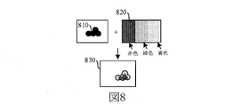
例示的に、図8は図7に示す実施例によって提供されるグレースケール画像を色付けする過程の模式図である。図8に示すように、カラーテクスチャ820に応じてグレースケール画像810を色付けすることによって、カラーホットスポットマップ830を得る。 Illustratively, FIG. 8 is a schematic diagram of the process of coloring the grayscale image provided by the embodiment shown in FIG. As shown in FIG. 8, a
ステップ706において、ホットスポット位置に対応するホットスポットマップを表示する。 In
可能な実現形態において、ホットスポットマップはホットスポットイベントに対応する模式図に重ねて表示されてもよい。例えば、ホットスポットイベントが仮想環境における仮想オブジェクトの移動分布を示すためのものである場合、ホットスポットマップが仮想環境に対応するマップに重ねて表示される。 In a possible implementation, the hotspot map may be overlaid on the schematic diagram corresponding to the hotspot event. For example, if the hotspot event is to show the movement distribution of virtual objects in the virtual environment, the hotspot map is superimposed on the map corresponding to the virtual environment.
以上のように、本実施例によって提供されるホットスポットマップの表示方法によれば、CPUによってホットスポット位置の座標データを確認してから、座標データに対応するポイントプリミティブをGPUに送信し、GPUによって座標データに対応するポイントプリミティブ集合を変換することによって、対応するパッチプリミティブ集合を得、パッチプリミティブ集合に対して色付けレンダリングを行って得られるホットスポットマップをレンダリングして表示する。これによって、ホットスポットマップの計算レンダリング中において、ほとんどの演算をGPUが行うことによって、CPUの計算負担を軽減し、CPUの計算リソースを他のプログラムロジックのために解放する。 As described above, according to the hotspot map display method provided by this embodiment, after the CPU confirms the coordinate data of the hotspot position, the point primitive corresponding to the coordinate data is transmitted to the GPU, and the GPU is used. By transforming the point primitive set corresponding to the coordinate data, the corresponding patch primitive set is obtained, and the hotspot map obtained by performing color rendering on the patch primitive set is rendered and displayed. This reduces the computational load on the CPU and frees the computational resources of the CPU for other program logic by having the GPU perform most of the computation during the computational rendering of the hotspot map.
本実施例によって提供される方法によれば、GPUによってパッチプリミティブに対して透過処理を行うことでグレースケール画像を得、グレースケール画像を対応的に色付けすることでカラーホットスポットマップを得る。これによって、GPUによりホットスポットマップに対して計算レンダリングを行い、CPUの計算リソースを他のプログラムロジックのために解放し、端末の稼働速度を向上させる。 According to the method provided by this embodiment, a grayscale image is obtained by performing transparency processing on the patch primitive by the GPU, and a color hotspot map is obtained by correspondingly coloring the grayscale image. As a result, the GPU performs computational rendering on the hotspot map, frees the computational resources of the CPU for other program logic, and improves the operating speed of the terminal.
選択的な実施例において、本願に係るホットスポットマップは、仮想環境における対象仮想オブジェクトの移動配置を示すためのものである。図9は本願の例示的な他の実施例によって提供されるホットスポットマップの表示方法のフローチャートである。該方法を端末に応用することを例として説明する。図9に示すように、該方法は次のステップを含む。 In a selective embodiment, the hotspot map according to the present application is for showing the moving arrangement of the target virtual object in the virtual environment. FIG. 9 is a flowchart of a hotspot map display method provided by the other exemplary embodiments of the present application. An application of the method to a terminal will be described as an example. As shown in FIG. 9, the method comprises the following steps.
ステップ901において、対象仮想オブジェクトの仮想環境における過去移動座標データを収集し、移動座標データをGPUに送信する。該過去移動座標データは、少なくとも1回の仮想対戦における対象仮想オブジェクトの移動座標を含む。 In
可能な実現形態において、対象仮想オブジェクトは対象アカウントによって作成された1つまたは複数の仮想オブジェクトであり、本願の実施例において、対象仮想オブジェクトが対象アカウントによって作成された1つの仮想オブジェクトであることを例として説明する。対象仮想オブジェクトの過去移動座標データを収集する前に、先ず、ホットスポットマップクエリインターフェースを表示する。該ホットスポットマップクエリインターフェースは、対象アカウントに対応する仮想オブジェクトの仮想環境における移動ホットスポットマップをクエリするためのものであり、ホットスポットマップクエリインターフェースは少なくとも1つの候補仮想オブジェクトを含む。 In a possible implementation, the target virtual object is one or more virtual objects created by the target account, and in the embodiments of the present application, the target virtual object is one virtual object created by the target account. This will be described as an example. Before collecting the past movement coordinate data of the target virtual object, first display the hotspot map query interface. The hotspot map query interface is for querying a moving hotspot map in the virtual environment of the virtual object corresponding to the target account, and the hotspot map query interface includes at least one candidate virtual object.
ホットスポットマップクエリインターフェースにおいて、対象仮想オブジェクトに対する選択操作を受信する。該選択操作は対象仮想オブジェクトの移動ホットスポットマップに対するクエリを示すためのものであり、選択操作に応じて、対象仮想オブジェクトの仮想環境における過去移動座標データを収集する。 In the hotspot map query interface, receive the selection operation for the target virtual object. The selection operation is for showing a query for the movement hotspot map of the target virtual object, and collects past movement coordinate data of the target virtual object in the virtual environment in response to the selection operation.
可能な実現形態において、ホットスポットマップクエリインターフェースは、対象対戦に参加する仮想オブジェクトの仮想環境における移動ホットスポットマップに対するクエリに用いられてもよい。ホットスポットマップクエリインターフェースは少なくとも1つの候補仮想オブジェクトを含み、ホットスポットマップクエリインターフェースにおいて、対象仮想オブジェクトに対する選択操作を受信し、選択操作に応じて1回または複数回の対戦での対象仮想オブジェクトの仮想環境における過去移動座標データを収集し、即ち、対象仮想オブジェクトの対象対戦における移動座標データを収集する。 In a possible implementation, the hotspot map query interface may be used to query a moving hotspot map in a virtual environment of virtual objects participating in a target match. The hotspot map query interface contains at least one candidate virtual object, in which the hotspot map query interface receives selection operations for the target virtual object and, depending on the selection operation, the target virtual object in one or more matches. Collect the past movement coordinate data in the virtual environment, that is, collect the movement coordinate data in the target battle of the target virtual object.
可能な実現形態において、移動座標データは、対象対戦の進行中にリアタイムで収集されてもよく、対象対戦の終了後に収集されてもよい。 In a possible implementation, the moving coordinate data may be collected in real time during the target battle or after the target battle is over.
可能な実現形態において、所定時間おきの対象仮想オブジェクトの仮想環境における位置情報を収集し、過去移動座標データを得る。 In a possible implementation, the position information of the target virtual object in the virtual environment at predetermined time intervals is collected, and the past moving coordinate data is obtained.
可能な実現形態において、対象仮想オブジェクトの少なくとも1回の仮想対戦における位置情報を収集する。位置情報は、仮想対戦全体において所定時間おきに収集される情報であってもよいし、仮想対戦における重要期間に対して所定時間おきに収集される情報、例えば、仮想対戦における10分目から20分目の期間内で所定時間おきに収集される情報であってもよい。 In a possible implementation, the location information of the target virtual object in at least one virtual battle is collected. The position information may be information collected at predetermined time intervals in the entire virtual battle, or information collected at predetermined time intervals for an important period in the virtual battle, for example, from the 10th minute to the 20th in the virtual battle. The information may be collected at predetermined time intervals within the minute period.
例示的に、図10は図9に示す実施例によって提供されるホットスポットマップクエリインターフェースのインターフェース模式図である。図10に示すように、ホットスポットマップクエリインターフェース1000は、対象仮想オブジェクト1011が含まれる少なくとも1つの候補仮想オブジェクト1010を含み、対象仮想オブジェクトに対する選択操作を受信すると、マップにおいて対象仮想オブジェクト1011に対応する移動ホットスポットマップ1012を表示する。 Illustratively, FIG. 10 is an interface schematic of the hotspot map query interface provided by the embodiment shown in FIG. As shown in FIG. 10, the hotspot map query interface 1000 includes at least one candidate
ステップ902において、GPUによって移動座標データに対応するポイントプリミティブ集合をパッチプリミティブ集合に変換する。 In
可能な実現形態において、GPUにおいてジオメトリシェーダ(Geometry Shader)によってポイントプリミティブ集合におけるポイントプリミティブをパッチプリミティブに変換し、パッチプリミティブ集合を得る。ポイントプリミティブ集合におけるポイントプリミティブは、ホットスポット位置の座標データから特定され、即ち、座標データに対応するポイントプリミティブがヒートマップにおけるパッチプリミティブに変換される。 In a possible implementation, a geometry shader in the GPU transforms a point primitive in a set of point primitives into a patch primitive to obtain a set of patch primitives. The point primitive in the point primitive set is identified from the coordinate data of the hotspot position, that is, the point primitive corresponding to the coordinate data is converted into the patch primitive in the heat map.
ステップ903において、GPUによってパッチプリミティブ集合に対して色付けレンダリングを行うことによって、ホットスポットマップを得る。 In
可能な実現形態において、GPUによってパッチプリミティブ集合に対応するグレースケール画像を取得し、シェーダによってグレースケール画像を色付けすることによって、ホットスポット位置に対応するカラーホットスポットマップを得る。 In a possible implementation, the GPU obtains the grayscale image corresponding to the patch primitive set and the shader colors the grayscale image to obtain a color hotspot map corresponding to the hotspot position.
可能な実現形態において、GPUによってパッチプリミティブ集合に対して半透過処理を行うことで、グレースケール画像を得、グレースケール画像を色付けする。 In a possible implementation, the GPU performs semi-transparent processing on the patch primitive set to obtain a grayscale image and color the grayscale image.
ステップ904において、仮想環境に対応するマップ表示領域においてホットスポット位置に対応するホットスポットマップを表示する。 In
以上のように、本実施例によって提供されるホットスポットマップの表示方法によれば、CPUによってホットスポット位置の座標データを確認してから、座標データに対応するポイントプリミティブをGPUに送信し、GPUによって座標データに対応するポイントプリミティブ集合を変換することによって、対応するパッチプリミティブ集合を得、パッチプリミティブ集合に対して色付けレンダリングを行ってからホットスポットマップを算出し、表示する。これによって、ホットスポットマップの計算レンダリング中において、ほとんどの演算をGPUが行うことによって、CPUの計算負担を軽減し、CPUの計算リソースを他のプログラムロジックのために解放する。 As described above, according to the hotspot map display method provided by this embodiment, after the CPU confirms the coordinate data of the hotspot position, the point primitive corresponding to the coordinate data is transmitted to the GPU, and the GPU is used. By transforming the point primitive set corresponding to the coordinate data by, the corresponding patch primitive set is obtained, the patch primitive set is colored and rendered, and then the hotspot map is calculated and displayed. This reduces the computational load on the CPU and frees the computational resources of the CPU for other program logic by having the GPU perform most of the computation during the computational rendering of the hotspot map.
本実施例によって提供される方法によれば、仮想対戦における仮想オブジェクトの移動配置について、対応するホットスポットマップを表示することで、対象仮想オブジェクトの移動状況がより直観的になり、また、ホットスポットマップのレンダリング中において、GPUによって演算を行うことで、CPUのリソースをゲームのロジック演算のために解放させ、端末の処理速度を向上させる。 According to the method provided by this embodiment, the movement status of the target virtual object becomes more intuitive by displaying the corresponding hotspot map for the movement arrangement of the virtual object in the virtual battle, and the hotspot is also provided. By performing the calculation by the GPU during the rendering of the map, the resources of the CPU are released for the logic calculation of the game, and the processing speed of the terminal is improved.
例示的に、図11は本願の例示的な他の実施例によって提供されるホットスポットマップのレンダリング過程の模式図である。該過程を仮想オブジェクトの移動配置の分析過程に応用することを例として説明する。図11に示すように、該過程は次のステップを含む。 Illustratively, FIG. 11 is a schematic diagram of the rendering process of a hotspot map provided by the other exemplary embodiments of the present application. It will be described as an example that the process is applied to the analysis process of the moving arrangement of virtual objects. As shown in FIG. 11, the process involves the following steps:
ステップ1101において、仮想オブジェクトの移動座標を収集し、座標リストを得る。 In
例示的に、現在進行中の仮想対戦を例として説明する。仮想オブジェクトの最近の所定時間内の移動座標を収集し、例えば、仮想オブジェクトの最近10分内の移動座標を収集し、また、5秒おきの仮想オブジェクトの仮想環境における移動座標を収集する。 Illustratively, an ongoing virtual battle will be described as an example. It collects the moving coordinates of the virtual object within the last predetermined time, for example, the moving coordinates of the virtual object within the last 10 minutes, and the moving coordinates of the virtual object in the virtual environment every 5 seconds.
ステップ1102において、座標リストをポイントプリミティブ集合に変換し、GPUに伝送する。 In
可能な実現形態において、CPUが座標データを収集した後、座標リストをポイントプリミティブ集合に変換し、後処理を行うようにGPUに伝送する。 In a possible implementation, after the CPU collects the coordinate data, the coordinate list is converted into a set of point primitives and transmitted to the GPU for post-processing.
ステップ1103において、ジオメトリシェーダによってポイントプリミティブ集合をパッチプリミティブ集合に変換する。 In
可能な実現形態において、GPUにおけるGeometry Shaderによってポイントプリミティブ集合をパッチプリミティブ集合に変換する。 In a possible implementation, the Geometry Shader on the GPU transforms the point primitive set into a patch primitive set.
ステップ1104において、半透過公式を用いて、Render Targetにグレースケール画像が形成されるまでパッチプリミティブ集合をレンダリングする。 In
可能な実現形態において、GPUは、半透過公式(One,OneMinusSrcAlpha)を用いてRender Targetにグレースケール画像が形成されるまで、パッチプリミティブ集合をレンダリングする。 In a possible implementation, the GPU uses a translucent formula (One, OneMinusSrcAlpha) to render a set of patch primitives until a grayscale image is formed on the Render Target.
ステップ1105において、カスタムシェーダによってグレースケール画像をカラー画像に変換し、マップにプロットしてホットスポットマップを形成する。 In
例示的に、図12は本願の例示的な一実施例によって提供されるGPUのグラフィックスレンダリングパイプラインによる構造模式図である。図12に示すように、ホットスポットマップのレンダリング中において、GPUのグラフィックスレンダリングパイプラインにおける頂点シェーダ1210、ジオメトリシェーダ1220およびフラグメントシェーダ1230を利用する。 Illustratively, FIG. 12 is a schematic structural diagram of the GPU graphics rendering pipeline provided by an exemplary embodiment of the present application. As shown in FIG. 12, during the rendering of the hotspot map, the
以上のように、本実施例によって提供されるホットスポットマップの表示方法によれば、CPUによってホットスポット位置の座標データを確認してから、座標データに対応するポイントプリミティブをGPUに送信し、GPUによって座標データに対応するポイントプリミティブ集合を変換することで、対応するパッチプリミティブ集合を得、パッチプリミティブ集合に対して色付けレンダリングを行うことによって、ホットスポットマップを得て表示する。これによって、ホットスポットマップの計算レンダリング中において、ほとんどの演算をGPUが行うことによって、CPUの計算負担を軽減し、CPUの計算リソースを他のプログラムロジックのために解放する。 As described above, according to the hotspot map display method provided by this embodiment, after the CPU confirms the coordinate data of the hotspot position, the point primitive corresponding to the coordinate data is transmitted to the GPU, and the GPU is used. By transforming the point primitive set corresponding to the coordinate data by, the corresponding patch primitive set is obtained, and by performing coloring rendering on the patch primitive set, a hotspot map is obtained and displayed. This reduces the computational load on the CPU and frees the computational resources of the CPU for other program logic by having the GPU perform most of the computation during the computational rendering of the hotspot map.
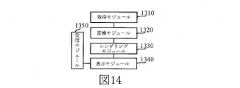
図13は本願の例示的な一実施例によって提供されるホットスポットマップの表示装置の構造ブロック図である。該装置を端末に応用することを例として説明する。該端末は図2に示す端末または図3に示すシステムにおける端末であってもよい。図13に示すように、該装置は次のモジュールを含む。 FIG. 13 is a structural block diagram of a hotspot map display device provided by an exemplary embodiment of the present application. The application of the device to a terminal will be described as an example. The terminal may be the terminal shown in FIG. 2 or the terminal in the system shown in FIG. As shown in FIG. 13, the device includes the following modules.
取得モジュール1310は、ホットスポット位置の座標データを収集し、前記座標データをGPUに送信するためのものである。 The
変換モジュール1320は、前記GPUによって、前記座標データに対応するポイントプリミティブ集合を、前記座標データに対応するパッチプリミティブからなるパッチプリミティブ集合に変換するためのものであって、前記ホットスポットマップにおけるホットスポット領域が前記パッチプリミティブを組み合わせることによって生成される。 The
レンダリングモジュール1330は、前記GPUによって前記パッチプリミティブ集合に対して色付けレンダリングを行うためのものである。 The
表示モジュール1340は、前記ホットスポット位置に対応する前記ホットスポットマップを表示するためのものである。 The
選択的な実施例において、前記取得モジュール1310は、前記GPUによって、前記パッチプリミティブ集合に対応するグレースケール画像を取得することにさらに用いられる。 In a selective embodiment, the
前記レンダリングモジュール1330は、シェーダによって、前記グレースケール画像を色付けすることで、前記ホットスポット位置に対応するカラーホットスポットマップを得ることにさらに用いられる。 The
選択的な実施例において、前記取得モジュール1310は、前記GPUによって、前記パッチプリミティブ集合に対応するグレースケール画像を取得することにさらに用いられる。 In a selective embodiment, the
前記レンダリングモジュール1330は、シェーダによって、前記グレースケール画像を色付けすることで、前記ホットスポット位置に対応するカラーホットスポットマップを得ることにさらに用いられる。 The
選択的な実施例において、前記取得モジュール1310は、前記GPUによって、前記パッチプリミティブ集合におけるパッチプリミティブに対して半透過処理を行うことで、前記パッチプリミティブ集合に対応する前記グレースケール画像を得ることにさらに用いられる。 In a selective embodiment, the
選択的な実施例において、前記取得モジュール1310は、前記ホットスポットマップにおけるホットスポット状況と正相関する色配置を含む参照カラーテクスチャを取得することにさらに用いられる。 In a selective embodiment, the
前記レンダリングモジュール1330は、前記シェーダによって、前記参照カラーテクスチャに応じて前記グレースケール画像を色付けすることで、前記ホットスポット位置に対応する前記カラーホットスポットマップを得ることにさらに用いられる。 The
選択的な実施例において、前記ホットスポットマップは仮想環境における対象仮想オブジェクトの移動配置を示すためのものである。 In a selective embodiment, the hotspot map is intended to show the movement and placement of target virtual objects in a virtual environment.
前記取得モジュール1310は、少なくとも1回の仮想対戦における前記対象仮想オブジェクトの移動座標を含む前記対象仮想オブジェクトの前記仮想環境における過去移動座標データを収集することにさらに用いられる。 The
選択的な実施例において、前記取得モジュール1310は、所定時間おきの前記対象仮想オブジェクトの前記仮想環境における位置情報を収集し、前記過去移動座標データを得ることにさらに用いられる。 In a selective embodiment, the
選択的な実施例において、前記表示モジュール1340は、ホットスポットマップクエリインターフェースにさらに用いられ、前記ホットスポットマップクエリインターフェースは、対象対戦に参加する仮想オブジェクトの前記仮想環境における移動ホットスポットマップをクエリするためのものであり、前記ホットスポットマップクエリインターフェースには、少なくとも1つの候補仮想オブジェクトを含む。 In a selective embodiment, the
図14に示すように、前記装置は、さらに次のモジュールを含む。 As shown in FIG. 14, the apparatus further includes the following modules.
受信モジュール1350は、前記ホットスポットマップクエリインターフェースにおいて、前記対象仮想オブジェクトの前記移動ホットスポットマップに対するクエリを示すための前記対象仮想オブジェクトに対する選択操作を受信するためのものである。 The
選択的な実施例において、前記表示モジュール1340は、前記仮想環境に対応するマップ表示領域において、前記ホットスポット位置に対応する前記ホットスポットマップを表示することにさらに用いられる。 In a selective embodiment, the
以上のように、本実施例によって提供されるホットスポットマップの表示装置によれば、CPUによってホットスポット位置の座標データを確認してから、座標データに対応するポイントプリミティブをGPUに送信すればよい。GPUによって座標データに対応するポイントプリミティブ集合を変換することで、対応するパッチプリミティブ集合を得、パッチプリミティブ集合に対して色付けレンダリングを行うことによって、ホットスポットマップを得て表示する。これによって、ホットスポットマップの計算レンダリング中において、ほとんどの演算をGPUが行うことによって、CPUの計算負担を軽減し、CPUの計算リソースを他のプログラムロジックのために解放する。 As described above, according to the hotspot map display device provided by this embodiment, the CPU may confirm the coordinate data of the hotspot position, and then send the point primitive corresponding to the coordinate data to the GPU. .. The corresponding patch primitive set is obtained by transforming the point primitive set corresponding to the coordinate data by the GPU, and the hotspot map is obtained and displayed by performing coloring rendering on the patch primitive set. This reduces the computational load on the CPU and frees the computational resources of the CPU for other program logic by having the GPU perform most of the computation during the computational rendering of the hotspot map.
説明すべきこととして、上記実施例によって提供されるホットスポットマップの表示装置について、上記各機能モジュールの区分を例として説明したが、実際の応用において、必要に応じて、上記機能を異なる機能モジュールに割り当てて完成させてもよい。即ち、機器の内部構造を異なる機能モジュールに区分して、以上の実施例に説明された機能の全てまたは一部を完成させてもよい。なお、上記実施例によって提供されるホットスポットマップの表示装置は、ホットスポットマップの表示方法とは同じ構想に属するものであるため、その具体的な実現手順は方法実施例を参照し、ここで重複して述べない。 As a matter of explanation, the hotspot map display device provided by the above embodiment has been described by taking the classification of each of the above functional modules as an example. It may be assigned to and completed. That is, the internal structure of the device may be divided into different functional modules to complete all or part of the functions described in the above embodiments. Since the hotspot map display device provided by the above embodiment belongs to the same concept as the hotspot map display method, the specific implementation procedure thereof is referred to in the method embodiment. I will not duplicate it.
図15は本願の例示的な一実施例によって提供される端末1500の構造ブロック図である。該端末1500は、スマートフォン、タブレット、MP3(Moving Picture Experts Group Audio Layer III,ムービング・ピクチャ・エクスパーツ・グループ・オーディオレイヤ3)プレーヤー、MP4(Moving Picture Experts Group Audio Layer IV,ムービング・ピクチャ・エクスパーツ・グループ・オーディオレイヤ4)プレーヤー、ノートパソコンまたは卓上コンピュータであってもよい。端末1500は、ユーザ機器、携帯型端末、ラップトップ端末、卓上端末等の他の名称で呼ばれることもある。 FIG. 15 is a structural block diagram of the terminal 1500 provided by an exemplary embodiment of the present application. The terminal 1500 includes a smartphone, a tablet, an MP3 (Moving Computer Experts Group Audio Layer III, Moving Picture Experts Group Audio Layer 3) player, and an MP4 (Moving Computer Experts Group Audio IV Parts) device. -Group audio layer 4) It may be a player, a laptop computer or a desktop computer. The terminal 1500 may be referred to by other names such as a user device, a portable terminal, a laptop terminal, and a desktop terminal.
一般的に、端末1500は、プロセッサ1501とメモリ1502とを備える。 Generally, the terminal 1500 includes a
プロセッサ1501は、1つまたは複数のプロセッサコアを含んでもよく、例えば、4コアプロセッサ、8コアプロセッサ等であってもよい。プロセッサ1501は、DSP(Digital Signal Processing,デジタル信号処理)、FPGA(Field Programmable Gate Array,フィールド・プログラマブル・ゲート・アレイ)、PLA(Programmable Logic Array,プログラマブル・ロジック・アレイ)のうちの少なくとも一種のハードウェアとして実現してもよい。プロセッサ1501は、ホストプロセッサとコプロセッサを含んでもよい。ホストプロセッサは、ウェイクアップ状態のデータを処理するためのプロセッサであり、CPU(Central Processing Unit,中央処理装置)とも呼ばれる。コプロセッサは、待機状態のデータを処理するための低消費電力プロセッサである。一部の実施例において、プロセッサ1501に、表示スクリーンに表示させる内容のレンダリングおよびプロットを行うためのGPU(Graphics Processing Unit,グラフィックスプロセッシングユニット)が集積されていてもよい。一部の実施例において、プロセッサ1501は、機械学習に関する計算操作を処理するためのAI(Artificial Intelligence,人工知能)プロセッサをさらに含んでもよい。 The
メモリ1502は、1つまたは複数のコンピュータ読み取り可能な記憶媒体を含んでもよい。該コンピュータ読み取り可能な記憶媒体は、非一過性のものであってもよい。メモリ1502は、高速ランダムアクセスメモリおよび不揮発性メモリ、例えば、1つまたは複数の磁気ディスク記憶装置、フラッシュメモリ記憶装置をさらに含んでもよい。一部の実施例において、メモリ1502における非一過性のコンピュータ読み取り可能な記憶媒体は、プロセッサ1501によって実行されることで、本願の方法実施例によって提供されるホットスポットマップの表示方法を実現するコマンドを少なくとも1つ記憶するためのものである。
一部の実施例において、端末1500は、任意に、周辺機器インターフェス1503および少なくとも1つの周辺機器をさらに備えてもよい。プロセッサ1501とメモリ1502と周辺機器インターフェス1503とは、バスまたは信号線により接続されてもよい。各周辺機器は、バス、信号線または回路基板により周辺機器インターフェス1503に接続されてもよい。具体的に、周辺機器は、RF回路1504、表示スクリーン1505、カメラユニット1506、オーディオ回路1507、測位ユニット1508および電源1509のうちの少なくとも1つを含んでもよい。 In some embodiments, the terminal 1500 may optionally further include a
周辺機器インターフェス1503は、I/O(Input/Output,入力/出力)に関する少なくとも1つの周辺機器をプロセッサ1501およびメモリ1502に接続するために用いてもよい。一部の実施例において、プロセッサ1501、メモリ1502および周辺機器インターフェス1503は、同一のチップまたは回路基板に集積される。他の実施例において、プロセッサ1501、メモリ1502および周辺機器インターフェス1503のうちのいずれか1つまたは2つは、独立したチップまたは回路基板において実現されてもよいが、本実施例において、これを限定しない。 The
RF回路1504は、RF(Radio Frequency,無線周波数)信号、即ち電磁気信号を送受信するためのものである。RF回路1504は、電磁気信号によって通信ネットワークおよび他の通信機器と通信する。RF回路1504は、電気信号を電磁気信号に変換して送信する、または、受信した電磁気信号を電気信号に変換する。任意に、RF回路1504は、アンテナシステム、RF送受信機、1つまたは複数のアンプ、チューナ、発振器、デジタル信号プロセッサ、コーデックチップセット、ユーザ加入識別モジュールカード等を含む。RF回路1504は、少なくとも1つの無線通信プロトコルによって他の端末と通信してもよい。該無線通信プロトコルは、ワールド・ワイド・ウェブ、メトロポリタンエリアネットワーク、イントラネット、各世代のモバイル通信ネットワーク(2G、3G、4Gおよび5G)、無線ローカルエリアネットワークおよび/またはWiFi(Wireless Fidelity,ワイヤレス・フィディリティ)ネットワークを含むが、これらに限られない。一部の実施例において、RF回路1504は、NFC(Near Field Communication,近距離無線通信)に関連する回路を含んでもよいが、本願において、これを限定しない。 The
表示スクリーン1505は、UI(User Interface,ユーザインターフェース)を表示するためのものである。該UIは、図形、テキスト、アイコン、ビデオおよびそれらの任意の組合せを含んでもよい。表示スクリーン1505がタッチスクリーンである場合、表示スクリーン1505は、表示スクリーン1505の表面または表面の上方のタッチ信号を収集する能力をさらに有する。該タッチ信号は制御信号としてプロセッサ1501に入力されて処理されてもよい。この場合、表示スクリーン1505は、仮想ボタンおよび/または仮想キーボード、即ちソフトボタンおよび/またはソフトキーボードを提供することに用いられてもよい。一部の実施例において、表示スクリーン1505は、端末1500の前面板に設けられる1つの表示スクリーンであってもよい。他の実施例において、表示スクリーン1505は、それぞれに端末1500の異なる表面に設けられ、または折り畳み型の少なくとも2つの表示スクリーンであってもよい。さらに他の実施例において、表示スクリーン1505は、端末1500の湾曲表面または折り畳み面に設けられるフレキシブル表示スクリーンであってもよい。さらに、表示スクリーン1505は、非矩形の不規則な図形、即ち異形スクリーンとしてもよい。表示スクリーン1505は、LCD(Liquid Crystal Display,液晶表示ディスプレイ)、OLED(Organic Light-Emitting Diode,有機発光ダイオード)等の材質により製造されてもよい。 The
カメラユニット1506は、画像またはビデオを収集するためのものである。任意に、カメラユニット1506はインカメラおよびアウトカメラを含む。通常、インカメラは端末の前面板に設けられ、アウトカメラは端末の裏面に設けられている。一部の実施例において、アウトカメラは、少なくとも2つあり、それぞれメインカメラ、被写界深度カメラ、広角カメラ、望遠カメラのうちのいずれか1つであり、このように、メインカメラと被写界深度カメラの連携により、背景ボケの機能を実現し、メインカメラと広角カメラの連携により、パノラマ撮影およびVR(Virtual Reality,仮想現実)撮影機能または他の連携撮影機能を実現する。一部の実施例において、カメラユニット1506はフラッシュをさらに有してもよい。フラッシュは単一色温度フラッシュであっても、2重色温度フラッシュであってもよい。2重色温度フラッシュとは、暖色系のフラッシュと寒色系のフラッシュの組み合わせであり、異なる色温度での光補償に用いられることができる。 The
オーディオ回路1507は、マイクロホンとスピーカを含んでもよい。マイクロホンは、ユーザおよび環境の音波を収集し、音波を電気信号に変換してプロセッサ1501に入力して処理し、またはRF回路1504に入力して音声通信を実現することに用いられる。ステレオ収集またはノイズキャンセルの目的から、マイクロホンは、端末1500の異なる箇所に複数設けられてもよい。マイクロホンは、アレイマイクロホンまたは無指向性収集式のマイクロホンであってもよい。スピーカは、プロセッサ1501またはRF回路1504からの電気信号を音波に変換するためのものである。スピーカは、従来のフィルムスピーカであっても、圧電セラミックスピーカであってもよい。スピーカが圧電セラミックスピーカである場合、電気信号を人間の可聴域にある音波に変換できるだけでなく、距離計測等の用途のために、電気信号を人間の不可聴域にある音波に変換することもできる。一部の実施例において、オーディオ回路1507は、さらにイヤホンジャックを含んでもよい。 The
測位ユニット1508は、端末1500の現在の地理位置を特定し、ナビゲーションまたはLBS(Location Based Service,位置情報サービス)を実現するためのものである。測位ユニット1508は、アメリカのGPS(Global Positioning System,グローバル・ポジショニング・システム)、中国の北斗システムまたはロシアのガリレオシステムに基づく測位ユニットであってもよい。 The
電源1509は、端末1500における各ユニットに給電するためのものである。電源1509は、交流電源、直流電源、使い捨て電池または充電式電池であってもよい。電源1509が充電式電池からなる場合、該充電式電池は有線充電電池または無線充電電池であってもよい。有線充電電池は有線回線によって充電される電池であり、無線充電電池は無線コイルによって充電される電池である。該充電式電池は高速充電技術をサポートしてもよい。 The
一部の実施例において、端末1500は1つまたは複数のセンサ1510をさらに有する。該1つまたは複数のセンサ1510は、加速度センサ1511、ジャイロセンサ1512、圧力センサ1513、指紋センサ1514、光学センサ1515および近接センサ1516を含むが、これらに限られない。 In some embodiments, the terminal 1500 further comprises one or more sensors 1510. The one or more sensors 1510 includes, but is not limited to, an acceleration sensor 1511, a gyro sensor 1512, a
加速度センサ1511は、端末1500で確立された座標系の3つの座標軸上の加速度の大きさを検出することができる。例えば、加速度センサ1511は、重力加速度の3つの座標軸における成分を検出することに用いられることができる。プロセッサ1501は、加速度センサ1511によって収集された重力加速度信号に応じて、横表示または縦表示でユーザインターフェースを表示するように、表示スクリーン1505を制御することができる。加速度センサ1511は、さらにゲームまたはユーザの運動データの収集に用いられてもよい。 The acceleration sensor 1511 can detect the magnitude of acceleration on the three coordinate axes of the coordinate system established in the
ジャイロセンサ1512は、端末1500の本体方向および回転角度を検出することができる。ジャイロセンサ1512は、加速度センサ1511と連携してユーザの端末1500に対する3D動作を収集することができる。プロセッサ1501は、ジャイロセンサ1512によって収集されたデータに応じて、動作検知(例えばユーザの傾斜操作に応じてUIを変更する)、撮像時の画像安定化、ゲーム制御および慣性ナビゲーションといった機能を実現することができる。 The gyro sensor 1512 can detect the main body direction and rotation angle of the
圧力センサ1513は、端末1500のサイドフレームおよび/または表示スクリーン1505の下層に設けられてもよい。圧力センサ1513が端末1500のサイドフレームに設けられた場合、ユーザの端末1500に対する把持信号を検出し、プロセッサ1501は、圧力センサ1513で収集された把持信号によって左右手の識別またはショットカット操作をすることができる。圧力センサ1513が表示スクリーン1505の下層に設けられた場合、プロセッサ1501は、ユーザの表示スクリーン1505に対する圧力操作に応じて、UIインターフェースにおける操作可能ウィジェットを制御することができる。操作可能ウィジェットは、ボタンウィジェット、スクロールバーウィジェット、アイコンウィジェット、メニューウィジェットのうちの少なくとも1つを含む。 The
指紋センサ1514は、ユーザの指紋を収集するためのものであり、プロセッサ1501により指紋センサ1514で収集された指紋に応じてユーザの身元を識別し、または、指紋センサ1514が収集された指紋に応じてユーザの身元を識別する。ユーザが正規ユーザとして認証された場合、プロセッサ1501は、該ユーザによる関連する機密操作を許可し、該機密操作は、スクリーンのアンロック、暗号化された情報の閲覧、ソフトウェアのダウンロード、支払いおよび設定の変更等を含む。指紋センサ1514は、端末1500の表面、裏面または側面に設けられてもよい。端末1500に物理的なボタンまたはメーカーのLogoが設けられた場合、指紋センサ1514は、物理的なボタンまたはメーカーのLogoと一体化されてもよい。 The
光学センサ1515は、環境光の強度を収集するためのものである。一実施例において、プロセッサ1501は、光学センサ1515で収集された環境光の強度に応じて、表示スクリーン1505の表示明るさを制御することができる。具体的に、環境光の強度が高い場合、表示スクリーン1505の表示明るさを高め、環境光の強度が低い場合、表示スクリーン1505の表示明るさを低減させる。他の実施例において、プロセッサ1501は、さらに光学センサ1515で収集された環境光の強度に応じて、カメラユニット1506の撮像パラメータを動的に調整することもできる。 The optical sensor 1515 is for collecting the intensity of ambient light. In one embodiment, the
近接センサ1516は、距離センサとも呼ばれ、通常、端末1500の前面板に設けられている。近接センサ1516は、ユーザと端末1500の表面との距離を収集するためのものである。一実施例において、近接センサ1516によりユーザと端末1500の表面との距離が小さくなりつつあることが検出された場合、プロセッサ1501は、表示スクリーン1505を、点灯状態から消灯状態に切り替えるように制御する。近接センサ1516によりユーザと端末1500の表面との距離が大きくなりつつあることが検出された場合、プロセッサ1501は、表示スクリーン1505を、消灯状態から点灯状態に切り替えるように制御する。 The proximity sensor 1516, also called a distance sensor, is usually provided on the front plate of the
当業者であれば、端末1500は、図15に示す構造によって限定されず、図示よりも多いまたは少ないユニットを含み、あるいは一部のユニットを組み合わせ、あるいは異なるユニット配置にしてもよいことを理解することができる。 Those skilled in the art will appreciate that the terminal 1500 is not limited by the structure shown in FIG. 15 and may include more or less units than shown, or may combine some units or may have different unit arrangements. be able to.
任意に、該コンピュータ読み取り可能な記憶媒体は、リードオンリーメモリ(ROM,Read Only Memory)、ランダムアクセスメモリ(RAM,Random Access Memory)、ソリッドステートドライブ(SSD,Solid State Drives)または光学ディスク等を含んでもよい。ランダムアクセスメモリは、抵抗変化型メモリ(ReRAM,Resistance Random Access Memory)やダイナミックランダムアクセスメモリ(DRAM,Dynamic Random Access Memory)を含んでもよい。上記本願の実施例の番号は説明の便宜上のものであり、実施例の優劣を示すためのものではない。 Optionally, the computer-readable storage medium includes read-only memory (ROM, Read Only Memory), random access memory (RAM, Random Access Memory), solid state drives (SSD, Solid State Drives), optical disks, and the like. But it may be. The random access memory may include a resistance change type memory (ReRAM, Random Access Memory) or a dynamic random access memory (DRAM, Dynamic Random Access Memory). The numbers of the examples of the present application are for convenience of explanation, and are not intended to indicate the superiority or inferiority of the examples.
例示的な実施例において、本願は、コンピュータ読み取り可能な記憶媒体をさらに提供する。該コンピュータ読み取り可能な記憶媒体には、プロセッサによりロードして実行されることで、上記各方法実施例によって提供されるホットスポットマップの表示方法を実現するコンピュータプログラムが少なくとも1つ記憶されている。 In an exemplary embodiment, the present application further provides a computer readable storage medium. The computer-readable storage medium stores at least one computer program that is loaded and executed by a processor to realize the hotspot map display method provided by each of the above method embodiments.
例示的な実施例において、コンピュータプログラム製品またはコンピュータプログラムをさらに提供する。該コンピュータプログラム製品またはコンピュータプログラムは、コンピュータ読み取り可能な記憶媒体に記憶されているコンピュータコマンドをむ。コンピュータ機器のプロセッサは、コンピュータ読み取り可能な記憶媒体から該コンピュータコマンドを読み取り、プロセッサによって該コンピュータコマンドを実行することで、該コンピュータ機器に上記各方法の実施例によって提供されるホットスポットマップの表示方法を実行させる。 In an exemplary embodiment, a computer program product or computer program is further provided. The computer program product or computer program contains computer commands stored in a computer-readable storage medium. A processor of a computer device reads the computer command from a computer-readable storage medium and executes the computer command by the processor to display a hotspot map provided to the computer device according to an embodiment of each of the above methods. To execute.
当業者であれば、上記実施例の全てまたは一部のステップを実現するために、ハードウェアによって完成してもよいし、プログラムによって関連するハードウェアを命令することで完成してもよいが、前記のプログラムは、コンピュータ読み取り可能な記憶媒体に記憶されてもよく、上記の記憶媒体はリードオンリーメモリ、磁気ディスクまたは光学ディスク等であってもよいことを理解することができる。 Those skilled in the art may complete it by hardware or by programmatically instructing the relevant hardware to achieve all or part of the steps of the above embodiment. It can be understood that the program may be stored in a computer-readable storage medium, which may be a read-only memory, a magnetic disk, an optical disk, or the like.
以上、本願の選択可能な実施例を説明したが、実施例は本願を制限するためのものではない。本願の精神および原則から逸脱せずに行われるあらゆる修正、等価置換、改良等は、いずれも本願の保護範囲内に含まれる。 Although the selectable examples of the present application have been described above, the examples are not intended to limit the present application. Any modifications, equivalent replacements, improvements, etc. made without departing from the spirit and principles of the present application are all within the scope of protection of the present application.
200 電子機器
220 オペレーティングシステム
222 アプリケーション
300 コンピュータシステム
320 第1機器
340 サーバ
360 第2機器
500 配列
510 座標
520 座標
530 座標
610 ポイントプリミティブ
620 パッチプリミティブ
810 グレースケール画像
820 カラーテクスチャ
830 カラーホットスポットマップ
1000 ホットスポットマップクエリインターフェース
1010 候補仮想オブジェクト
1011 対象仮想オブジェクト
1012 移動ホットスポットマップ
1210 頂点シェーダ
1220 ジオメトリシェーダ
1230 フラグメントシェーダ
1310 取得モジュール
1320 変換モジュール
1330 レンダリングモジュール
1340 表示モジュール
1350 受信モジュール
1500 端末
1501 プロセッサ
1502 メモリ
1503 周辺機器インターフェス
1504 RF回路
1505 表示スクリーン
1506 カメラユニット
1507 オーディオ回路
1508 測位ユニット
1509 電源
1510 センサ
1511 加速度センサ
1512 ジャイロセンサ
1513 圧力センサ
1514 指紋センサ
1515 光学センサ
1516 近接センサ
200 Electronic Equipment 220 Operating System 222
Claims (18)
Translated fromJapanese前記GPUによって、前記座標データに対応するポイントプリミティブ集合を、前記座標データに対応するパッチプリミティブからなるパッチプリミティブ集合に変換することであって、前記ホットスポットマップにおけるホットスポット領域が前記パッチプリミティブを組み合わせることによって生成される前記ことと、
前記GPUによって、前記パッチプリミティブ集合に対して色付けレンダリングを行うことで、前記ホットスポットマップを得ることと、
前記ホットスポット位置に対応する前記ホットスポットマップを表示することと、
を含むことを特徴とするホットスポットマップの表示方法。Collecting the coordinate data of the hotspot position and transmitting the coordinate data to the GPU,
The GPU converts a set of point primitives corresponding to the coordinate data into a set of patch primitives consisting of patch primitives corresponding to the coordinate data, wherein the hotspot area in the hotspot map combines the patch primitives. And the above generated by
By performing color rendering on the patch primitive set by the GPU, the hotspot map can be obtained.
Displaying the hotspot map corresponding to the hotspot position and
How to display a hotspot map, characterized by including.
前記GPUによって、前記パッチプリミティブ集合に対応するグレースケール画像を取得することと、
シェーダによって、前記グレースケール画像を色付けすることで、前記ホットスポット位置に対応するカラーホットスポットマップを得ることと、を含むことを特徴とする請求項1に記載の方法。The above is to obtain the hotspot map by performing color rendering on the patch primitive set by the GPU.
Acquiring a grayscale image corresponding to the patch primitive set by the GPU,
The method according to claim 1, wherein a color hotspot map corresponding to the hotspot position is obtained by coloring the grayscale image with a shader.
前記GPUによって、前記パッチプリミティブ集合におけるパッチプリミティブに対して半透過処理を行うことで、前記パッチプリミティブ集合に対応する前記グレースケール画像を得ること、を含むことを特徴とする請求項2に記載の方法。Acquiring a grayscale image corresponding to the patch primitive set by the GPU.
The second aspect of claim 2, wherein the GPU performs semi-transparent processing on the patch primitives in the patch primitive set to obtain the grayscale image corresponding to the patch primitive set. Method.
前記ホットスポットマップにおけるホットスポット状況と正相関する色配置を含む参照カラーテクスチャを取得することと、
前記シェーダによって、前記参照カラーテクスチャに応じて前記グレースケール画像を色付けすることで、前記ホットスポット位置に対応する前記カラーホットスポットマップを得ることと、を含むことを特徴とする請求項2に記載の方法。By coloring the grayscale image with the shader, a color hotspot map corresponding to the hotspot position is obtained.
Obtaining a reference color texture that includes a color arrangement that is positively correlated with the hotspot situation in the hotspot map.
2. The second aspect of the present invention is characterized in that the shader colors the grayscale image according to the reference color texture to obtain the color hotspot map corresponding to the hotspot position. the method of.
前記ホットスポット位置の座標データを収集する前記ことは、
少なくとも1回の仮想対戦における前記対象仮想オブジェクトの移動座標を含む前記対象仮想オブジェクトの前記仮想環境における過去移動座標データを収集すること、を含むことを特徴とする請求項1から4のいずれか一項に記載の方法。The hotspot map is for showing the movement arrangement of the target virtual object in the virtual environment.
Collecting the coordinate data of the hotspot position
One of claims 1 to 4, wherein the collection includes past movement coordinate data of the target virtual object in the virtual environment including the movement coordinates of the target virtual object in at least one virtual battle. The method described in the section.
所定時間おきの前記対象仮想オブジェクトの前記仮想環境における位置情報を収集し、前記過去移動座標データを得ること、を含むことを特徴とする請求項5に記載の方法。Collecting the past movement coordinate data of the target virtual object in the virtual environment The above is
The method according to claim 5, further comprising collecting the position information of the target virtual object in the virtual environment at predetermined time intervals and obtaining the past moving coordinate data.
対象対戦に参加する仮想オブジェクトの前記仮想環境における移動ホットスポットマップをクエリするためのホットスポットマップクエリインターフェースであって、少なくとも1つの候補仮想オブジェクトを含む前記ホットスポットマップクエリインターフェースを表示することと、
前記ホットスポットマップクエリインターフェースにおいて、前記対象仮想オブジェクトの前記移動ホットスポットマップに対するクエリを示すための前記対象仮想オブジェクトに対する選択操作を受信することと、をさらに含むことを特徴とする請求項5に記載の方法。Before collecting the past movement coordinate data of the target virtual object in the virtual environment,
A hotspot map query interface for querying a moving hotspot map of a virtual object participating in a target match in the virtual environment, and displaying the hotspot map query interface including at least one candidate virtual object.
5. The fifth aspect of the invention, wherein the hotspot map query interface further includes receiving a selection operation for the target virtual object to indicate a query for the moving hotspot map of the target virtual object. the method of.
前記仮想環境に対応するマップ表示領域において、前記ホットスポット位置に対応する前記ホットスポットマップを表示すること、を含むことを特徴とする請求項5に記載の方法。Displaying the hotspot map corresponding to the hotspot location
The method according to claim 5, wherein the hotspot map corresponding to the hotspot position is displayed in the map display area corresponding to the virtual environment.
前記GPUによって、前記座標データに対応するポイントプリミティブ集合を、前記座標データに対応するパッチプリミティブからなるパッチプリミティブ集合に変換するための変換モジュールであって、前記ホットスポットマップにおけるホットスポット領域が前記パッチプリミティブを組み合わせることによって生成される前記変換モジュールと、
前記GPUによって、前記パッチプリミティブ集合に対して色付けレンダリングを行うことで、前記ホットスポットマップを得るためのレンダリングモジュールと、
前記ホットスポット位置に対応する前記ホットスポットマップを表示するための表示モジュールと、
を備えることを特徴とするホットスポットマップの表示装置。An acquisition module for collecting coordinate data of hotspot positions and transmitting the coordinate data to the GPU,
It is a conversion module for converting a point primitive set corresponding to the coordinate data into a patch primitive set consisting of patch primitives corresponding to the coordinate data by the GPU, and the hotspot area in the hotspot map is the patch. The conversion module generated by combining the primitives and
A rendering module for obtaining the hotspot map by performing color rendering on the patch primitive set by the GPU.
A display module for displaying the hotspot map corresponding to the hotspot position,
A hotspot map display device characterized by being equipped with.
前記レンダリングモジュールは、シェーダによって、前記グレースケール画像を色付けすることで、前記ホットスポット位置に対応するカラーホットスポットマップを得ることにさらに用いられることを特徴とする請求項9に記載の装置。The acquisition module is further used by the GPU to acquire a grayscale image corresponding to the patch primitive set.
The apparatus according to claim 9, wherein the rendering module is further used to obtain a color hotspot map corresponding to the hotspot position by coloring the grayscale image with a shader.
前記レンダリングモジュールは、前記シェーダによって、前記参照カラーテクスチャに応じて前記グレースケール画像を色付けすることで、前記ホットスポット位置に対応する前記カラーホットスポットマップを得ることにさらに用いられることを特徴とする請求項10に記載の装置。The acquisition module is further used to acquire a reference color texture that includes a color arrangement that is positively correlated with the hotspot situation in the hotspot map.
The rendering module is further used to obtain the color hotspot map corresponding to the hotspot location by coloring the grayscale image according to the reference color texture with the shader. The device according to claim 10.
前記取得モジュールは、少なくとも1回の仮想対戦における前記対象仮想オブジェクトの移動座標を含む前記対象仮想オブジェクトの前記仮想環境における過去移動座標データを収集することにさらに用いられることを特徴とする請求項9から12のいずれか一項に記載の装置。The hotspot map is for showing the movement arrangement of the target virtual object in the virtual environment.
9. The acquisition module is further used to collect past movement coordinate data of the target virtual object in the virtual environment including the movement coordinates of the target virtual object in at least one virtual battle. The device according to any one of 12 to 12.
前記装置は、
前記ホットスポットマップクエリインターフェースにおいて、前記対象仮想オブジェクトの前記移動ホットスポットマップに対するクエリを示すための前記対象仮想オブジェクトに対する選択操作を受信するための受信モジュールをさらに備えることを特徴とする請求項13に記載の装置。The display module is a hotspot map query interface for querying a moving hotspot map of a virtual object participating in a target match in the virtual environment, and is a hotspot map query interface including at least one candidate virtual object. Further used,
The device is
13. The hotspot map query interface is further comprising a receiving module for receiving a selection operation for the target virtual object for indicating a query for the moving hotspot map of the target virtual object. The device described.
Applications Claiming Priority (3)
| Application Number | Priority Date | Filing Date | Title |
|---|---|---|---|
| CN202010099511.9 | 2020-02-18 | ||
| CN202010099511.9ACN111325822B (en) | 2020-02-18 | 2020-02-18 | Method, device and equipment for displaying hot spot diagram and readable storage medium |
| PCT/CN2020/125823WO2021164315A1 (en) | 2020-02-18 | 2020-11-02 | Hotspot map display method and apparatus, and computer device and readable storage medium |
Publications (2)
| Publication Number | Publication Date |
|---|---|
| JP2022532044Atrue JP2022532044A (en) | 2022-07-13 |
| JP7186901B2 JP7186901B2 (en) | 2022-12-09 |
Family
ID=71172643
Family Applications (1)
| Application Number | Title | Priority Date | Filing Date |
|---|---|---|---|
| JP2021564355AActiveJP7186901B2 (en) | 2020-02-18 | 2020-11-02 | HOTSPOT MAP DISPLAY METHOD, DEVICE, COMPUTER DEVICE AND READABLE STORAGE MEDIUM |
Country Status (6)
| Country | Link |
|---|---|
| US (1) | US11790607B2 (en) |
| JP (1) | JP7186901B2 (en) |
| KR (1) | KR102633468B1 (en) |
| CN (1) | CN111325822B (en) |
| SG (1) | SG11202111637VA (en) |
| WO (1) | WO2021164315A1 (en) |
Cited By (1)
| Publication number | Priority date | Publication date | Assignee | Title |
|---|---|---|---|---|
| WO2024057573A1 (en)* | 2022-09-13 | 2024-03-21 | 株式会社日立製作所 | Travel demand analysis system, and travel demand analysis method |
Families Citing this family (7)
| Publication number | Priority date | Publication date | Assignee | Title |
|---|---|---|---|---|
| CN111325822B (en) | 2020-02-18 | 2022-09-06 | 腾讯科技(深圳)有限公司 | Method, device and equipment for displaying hot spot diagram and readable storage medium |
| CN114241109B (en)* | 2021-12-21 | 2025-03-14 | 南京华苏科技有限公司 | A method for generating three-dimensional thermal cloud map based on webgl |
| CN114255301B (en)* | 2021-12-21 | 2025-03-14 | 南京华苏科技有限公司 | A method for generating thermal cloud map based on webgl |
| CN114419099B (en)* | 2022-01-18 | 2024-08-13 | 腾讯科技(深圳)有限公司 | Method for capturing motion trail of virtual object to be rendered |
| CN114768252B (en)* | 2022-05-16 | 2025-06-20 | 网易(杭州)网络有限公司 | Game scene display method, device, electronic device and storage medium |
| CN115830178B (en)* | 2022-12-05 | 2023-09-08 | 珠海芯聚科技有限公司 | Integrated circuit hot spot diagram display method, equipment and storage medium |
| CN117786913B (en)* | 2024-01-09 | 2025-09-09 | 国网经济技术研究院有限公司 | Discrete rendering method for power grid equipment model, electronic equipment and storage medium |
Citations (1)
| Publication number | Priority date | Publication date | Assignee | Title |
|---|---|---|---|---|
| CN110738722A (en)* | 2019-10-10 | 2020-01-31 | 支付宝(杭州)信息技术有限公司 | thermodynamic diagram texture generation method, device and equipment |
Family Cites Families (18)
| Publication number | Priority date | Publication date | Assignee | Title |
|---|---|---|---|---|
| JP3611808B2 (en)* | 2001-08-02 | 2005-01-19 | コナミ株式会社 | GAME DEVICE, GAME CONTROL METHOD, AND PROGRAM |
| CN105741334B (en)* | 2014-12-11 | 2019-06-18 | 阿里巴巴集团控股有限公司 | Thermodynamic chart providing method and device |
| CN104881839B (en)* | 2015-04-24 | 2017-11-07 | 中国电子进出口总公司 | It is a kind of based on the focus drawing generating method accelerated parallel |
| JP5899364B1 (en)* | 2015-09-17 | 2016-04-06 | 株式会社Cygames | PROGRAM, ELECTRONIC DEVICE, SYSTEM, AND METHOD FOR DETERMINING RESOURCE ALLOCATION FOR PREDICTING AND Rendering Player Intent |
| WO2018103633A1 (en)* | 2016-12-06 | 2018-06-14 | 腾讯科技(深圳)有限公司 | Image processing method and device |
| WO2019060268A1 (en)* | 2017-09-19 | 2019-03-28 | Covestro Llc | Techniques to custom design products |
| CN109658455B (en)* | 2017-10-11 | 2023-04-18 | 阿里巴巴集团控股有限公司 | Image processing method and processing apparatus |
| KR20210055038A (en)* | 2018-07-16 | 2021-05-14 | 악셀 로보틱스 코포레이션 | Autonomous store tracking system |
| JP7329825B2 (en)* | 2018-07-25 | 2023-08-21 | 公立大学法人岩手県立大学 | Information provision system, information provision method, program |
| CN109189878B (en)* | 2018-09-18 | 2019-08-23 | 图普科技(广州)有限公司 | A kind of crowd's thermodynamic chart preparation method and device |
| CN109636894B (en)* | 2018-10-31 | 2022-10-25 | 成都四方伟业软件股份有限公司 | Dynamic three-dimensional thermodynamic calculation method and system based on pixel rasterization |
| CN109492070A (en)* | 2018-11-06 | 2019-03-19 | 深圳航天智慧城市系统技术研究院有限公司 | A kind of city macroscopic view scene three-dimensional visualization plateform system |
| CN109621413A (en)* | 2018-12-28 | 2019-04-16 | 腾讯科技(深圳)有限公司 | Rendering indication method, device, terminal and the storage medium of game picture |
| CN109726261A (en)* | 2019-01-07 | 2019-05-07 | 北京超图软件股份有限公司 | A kind of heating power drawing generating method and device |
| CN110264539A (en)* | 2019-06-18 | 2019-09-20 | 北京字节跳动网络技术有限公司 | Image generating method and device |
| CN110544290A (en)* | 2019-09-06 | 2019-12-06 | 广东省城乡规划设计研究院 | data rendering method and device |
| CN110766770B (en)* | 2019-10-16 | 2021-07-20 | 腾讯科技(深圳)有限公司 | Thermodynamic diagram generation method and device, readable storage medium and computer equipment |
| CN111325822B (en)* | 2020-02-18 | 2022-09-06 | 腾讯科技(深圳)有限公司 | Method, device and equipment for displaying hot spot diagram and readable storage medium |
- 2020
- 2020-02-18CNCN202010099511.9Apatent/CN111325822B/enactiveActive
- 2020-11-02WOPCT/CN2020/125823patent/WO2021164315A1/ennot_activeCeased
- 2020-11-02KRKR1020217035911Apatent/KR102633468B1/enactiveActive
- 2020-11-02JPJP2021564355Apatent/JP7186901B2/enactiveActive
- 2020-11-02SGSG11202111637VApatent/SG11202111637VA/enunknown
- 2021
- 2021-11-15USUS17/527,005patent/US11790607B2/enactiveActive
Patent Citations (1)
| Publication number | Priority date | Publication date | Assignee | Title |
|---|---|---|---|---|
| CN110738722A (en)* | 2019-10-10 | 2020-01-31 | 支付宝(杭州)信息技术有限公司 | thermodynamic diagram texture generation method, device and equipment |
Cited By (1)
| Publication number | Priority date | Publication date | Assignee | Title |
|---|---|---|---|---|
| WO2024057573A1 (en)* | 2022-09-13 | 2024-03-21 | 株式会社日立製作所 | Travel demand analysis system, and travel demand analysis method |
Also Published As
| Publication number | Publication date |
|---|---|
| CN111325822A (en) | 2020-06-23 |
| KR102633468B1 (en) | 2024-02-02 |
| US11790607B2 (en) | 2023-10-17 |
| KR20210147033A (en) | 2021-12-06 |
| CN111325822B (en) | 2022-09-06 |
| SG11202111637VA (en) | 2021-11-29 |
| JP7186901B2 (en) | 2022-12-09 |
| WO2021164315A1 (en) | 2021-08-26 |
| US20220076487A1 (en) | 2022-03-10 |
Similar Documents
| Publication | Publication Date | Title |
|---|---|---|
| US11256384B2 (en) | Method, apparatus and device for view switching of virtual environment, and storage medium | |
| JP7186901B2 (en) | HOTSPOT MAP DISPLAY METHOD, DEVICE, COMPUTER DEVICE AND READABLE STORAGE MEDIUM | |
| US11458395B2 (en) | Method for displaying information in a virtual environment | |
| WO2019205838A1 (en) | Method, terminal, and computer apparatus for displaying distance information in virtual scene | |
| CN112156464A (en) | Two-dimensional image display method, device and equipment of virtual object and storage medium | |
| JP2022509634A (en) | How to observe virtual items in a virtual environment, appliances and computer programs | |
| CN111273780B (en) | Animation playing method, device and equipment based on virtual environment and storage medium | |
| CN109634413B (en) | Method, device and storage medium for observing virtual environment | |
| CN111603771B (en) | Animation generation method, device, equipment and medium | |
| CN111603770A (en) | Virtual environment picture display method, device, equipment and medium | |
| CN110496392B (en) | Virtual object control method, device, terminal and storage medium | |
| CN113134235A (en) | Map element adding method, device, terminal and storage medium | |
| CN111589141A (en) | Virtual environment picture display method, device, equipment and medium | |
| CN111026318A (en) | Animation playing method, device and equipment based on virtual environment and storage medium | |
| CN113559495A (en) | Method, device, equipment and storage medium for releasing skill of virtual object | |
| CN113577765A (en) | User interface display method, device, equipment and storage medium | |
| CN112306332B (en) | Method, device and equipment for determining selected target and storage medium | |
| CN113769397A (en) | Virtual object setting method, device, equipment, medium and program product | |
| CN111921191A (en) | Display method and device of status icon, terminal and storage medium | |
| CN113058266B (en) | Method, device, equipment and medium for displaying scene fonts in virtual environment | |
| HK40024105B (en) | Method and apparatus for displaying heat map, device and readable storage medium | |
| HK40024105A (en) | Method and apparatus for displaying heat map, device and readable storage medium | |
| HK40023676B (en) | Method and apparatus for playing animation based on virtual environment, device and storage medium | |
| HK40023676A (en) | Method and apparatus for playing animation based on virtual environment, device and storage medium | |
| HK40048690A (en) | Display method of scene fonts in virtual environment, device, equipment and medium |
Legal Events
| Date | Code | Title | Description |
|---|---|---|---|
| A521 | Request for written amendment filed | Free format text:JAPANESE INTERMEDIATE CODE: A523 Effective date:20211028 | |
| A621 | Written request for application examination | Free format text:JAPANESE INTERMEDIATE CODE: A621 Effective date:20211028 | |
| A977 | Report on retrieval | Free format text:JAPANESE INTERMEDIATE CODE: A971007 Effective date:20221024 | |
| TRDD | Decision of grant or rejection written | ||
| A01 | Written decision to grant a patent or to grant a registration (utility model) | Free format text:JAPANESE INTERMEDIATE CODE: A01 Effective date:20221031 | |
| A61 | First payment of annual fees (during grant procedure) | Free format text:JAPANESE INTERMEDIATE CODE: A61 Effective date:20221129 | |
| R150 | Certificate of patent or registration of utility model | Ref document number:7186901 Country of ref document:JP Free format text:JAPANESE INTERMEDIATE CODE: R150 |