JP2022531871A - Preparation of the tibia to receive the tibial implant component of the replacement ankle - Google Patents
Preparation of the tibia to receive the tibial implant component of the replacement ankleDownload PDFInfo
- Publication number
- JP2022531871A JP2022531871AJP2021565834AJP2021565834AJP2022531871AJP 2022531871 AJP2022531871 AJP 2022531871AJP 2021565834 AJP2021565834 AJP 2021565834AJP 2021565834 AJP2021565834 AJP 2021565834AJP 2022531871 AJP2022531871 AJP 2022531871A
- Authority
- JP
- Japan
- Prior art keywords
- cutting tool
- tool bit
- tibia
- talus
- power driver
- Prior art date
- Legal status (The legal status is an assumption and is not a legal conclusion. Google has not performed a legal analysis and makes no representation as to the accuracy of the status listed.)
- Pending
Links
Images


Classifications
- A—HUMAN NECESSITIES
- A61—MEDICAL OR VETERINARY SCIENCE; HYGIENE
- A61B—DIAGNOSIS; SURGERY; IDENTIFICATION
- A61B17/00—Surgical instruments, devices or methods
- A61B17/14—Surgical saws
- A61B17/15—Guides therefor
- A—HUMAN NECESSITIES
- A61—MEDICAL OR VETERINARY SCIENCE; HYGIENE
- A61B—DIAGNOSIS; SURGERY; IDENTIFICATION
- A61B17/00—Surgical instruments, devices or methods
- A61B17/16—Instruments for performing osteoclasis; Drills or chisels for bones; Trepans
- A61B17/1662—Instruments for performing osteoclasis; Drills or chisels for bones; Trepans for particular parts of the body
- A61B17/1682—Instruments for performing osteoclasis; Drills or chisels for bones; Trepans for particular parts of the body for the foot or ankle
- A—HUMAN NECESSITIES
- A61—MEDICAL OR VETERINARY SCIENCE; HYGIENE
- A61B—DIAGNOSIS; SURGERY; IDENTIFICATION
- A61B17/00—Surgical instruments, devices or methods
- A61B17/16—Instruments for performing osteoclasis; Drills or chisels for bones; Trepans
- A61B17/1613—Component parts
- A61B17/1622—Drill handpieces
- A61B17/1624—Drive mechanisms therefor
- A—HUMAN NECESSITIES
- A61—MEDICAL OR VETERINARY SCIENCE; HYGIENE
- A61B—DIAGNOSIS; SURGERY; IDENTIFICATION
- A61B17/00—Surgical instruments, devices or methods
- A61B17/16—Instruments for performing osteoclasis; Drills or chisels for bones; Trepans
- A61B17/164—Instruments for performing osteoclasis; Drills or chisels for bones; Trepans intramedullary
- A—HUMAN NECESSITIES
- A61—MEDICAL OR VETERINARY SCIENCE; HYGIENE
- A61B—DIAGNOSIS; SURGERY; IDENTIFICATION
- A61B17/00—Surgical instruments, devices or methods
- A61B17/16—Instruments for performing osteoclasis; Drills or chisels for bones; Trepans
- A61B17/17—Guides or aligning means for drills, mills, pins or wires
- A61B17/1717—Guides or aligning means for drills, mills, pins or wires for applying intramedullary nails or pins
- A—HUMAN NECESSITIES
- A61—MEDICAL OR VETERINARY SCIENCE; HYGIENE
- A61B—DIAGNOSIS; SURGERY; IDENTIFICATION
- A61B17/00—Surgical instruments, devices or methods
- A61B17/16—Instruments for performing osteoclasis; Drills or chisels for bones; Trepans
- A61B17/17—Guides or aligning means for drills, mills, pins or wires
- A61B17/1739—Guides or aligning means for drills, mills, pins or wires specially adapted for particular parts of the body
- A61B17/1775—Guides or aligning means for drills, mills, pins or wires specially adapted for particular parts of the body for the foot or ankle
- A—HUMAN NECESSITIES
- A61—MEDICAL OR VETERINARY SCIENCE; HYGIENE
- A61F—FILTERS IMPLANTABLE INTO BLOOD VESSELS; PROSTHESES; DEVICES PROVIDING PATENCY TO, OR PREVENTING COLLAPSING OF, TUBULAR STRUCTURES OF THE BODY, e.g. STENTS; ORTHOPAEDIC, NURSING OR CONTRACEPTIVE DEVICES; FOMENTATION; TREATMENT OR PROTECTION OF EYES OR EARS; BANDAGES, DRESSINGS OR ABSORBENT PADS; FIRST-AID KITS
- A61F2/00—Filters implantable into blood vessels; Prostheses, i.e. artificial substitutes or replacements for parts of the body; Appliances for connecting them with the body; Devices providing patency to, or preventing collapsing of, tubular structures of the body, e.g. stents
- A61F2/02—Prostheses implantable into the body
- A61F2/30—Joints
- A61F2/46—Special tools for implanting artificial joints
- A61F2/4603—Special tools for implanting artificial joints for insertion or extraction of endoprosthetic joints or of accessories thereof
- A61F2/4606—Special tools for implanting artificial joints for insertion or extraction of endoprosthetic joints or of accessories thereof of wrists or ankles; of hands, e.g. fingers; of feet, e.g. toes
- A—HUMAN NECESSITIES
- A61—MEDICAL OR VETERINARY SCIENCE; HYGIENE
- A61B—DIAGNOSIS; SURGERY; IDENTIFICATION
- A61B17/00—Surgical instruments, devices or methods
- A61B17/16—Instruments for performing osteoclasis; Drills or chisels for bones; Trepans
- A61B17/1613—Component parts
- A61B17/1622—Drill handpieces
- A—HUMAN NECESSITIES
- A61—MEDICAL OR VETERINARY SCIENCE; HYGIENE
- A61B—DIAGNOSIS; SURGERY; IDENTIFICATION
- A61B17/00—Surgical instruments, devices or methods
- A61B17/56—Surgical instruments or methods for treatment of bones or joints; Devices specially adapted therefor
- A61B2017/564—Methods for bone or joint treatment
- A—HUMAN NECESSITIES
- A61—MEDICAL OR VETERINARY SCIENCE; HYGIENE
- A61F—FILTERS IMPLANTABLE INTO BLOOD VESSELS; PROSTHESES; DEVICES PROVIDING PATENCY TO, OR PREVENTING COLLAPSING OF, TUBULAR STRUCTURES OF THE BODY, e.g. STENTS; ORTHOPAEDIC, NURSING OR CONTRACEPTIVE DEVICES; FOMENTATION; TREATMENT OR PROTECTION OF EYES OR EARS; BANDAGES, DRESSINGS OR ABSORBENT PADS; FIRST-AID KITS
- A61F2/00—Filters implantable into blood vessels; Prostheses, i.e. artificial substitutes or replacements for parts of the body; Appliances for connecting them with the body; Devices providing patency to, or preventing collapsing of, tubular structures of the body, e.g. stents
- A61F2/02—Prostheses implantable into the body
- A61F2/30—Joints
- A61F2/42—Joints for wrists or ankles; for hands, e.g. fingers; for feet, e.g. toes
- A61F2/4202—Joints for wrists or ankles; for hands, e.g. fingers; for feet, e.g. toes for ankles
- A61F2002/4205—Tibial components
- A—HUMAN NECESSITIES
- A61—MEDICAL OR VETERINARY SCIENCE; HYGIENE
- A61F—FILTERS IMPLANTABLE INTO BLOOD VESSELS; PROSTHESES; DEVICES PROVIDING PATENCY TO, OR PREVENTING COLLAPSING OF, TUBULAR STRUCTURES OF THE BODY, e.g. STENTS; ORTHOPAEDIC, NURSING OR CONTRACEPTIVE DEVICES; FOMENTATION; TREATMENT OR PROTECTION OF EYES OR EARS; BANDAGES, DRESSINGS OR ABSORBENT PADS; FIRST-AID KITS
- A61F2/00—Filters implantable into blood vessels; Prostheses, i.e. artificial substitutes or replacements for parts of the body; Appliances for connecting them with the body; Devices providing patency to, or preventing collapsing of, tubular structures of the body, e.g. stents
- A61F2/02—Prostheses implantable into the body
- A61F2/30—Joints
- A61F2/42—Joints for wrists or ankles; for hands, e.g. fingers; for feet, e.g. toes
- A61F2/4202—Joints for wrists or ankles; for hands, e.g. fingers; for feet, e.g. toes for ankles
- A61F2002/4207—Talar components
Landscapes
- Health & Medical Sciences (AREA)
- Life Sciences & Earth Sciences (AREA)
- Surgery (AREA)
- Orthopedic Medicine & Surgery (AREA)
- Oral & Maxillofacial Surgery (AREA)
- Engineering & Computer Science (AREA)
- Biomedical Technology (AREA)
- Heart & Thoracic Surgery (AREA)
- Animal Behavior & Ethology (AREA)
- General Health & Medical Sciences (AREA)
- Public Health (AREA)
- Veterinary Medicine (AREA)
- Medical Informatics (AREA)
- Molecular Biology (AREA)
- Dentistry (AREA)
- Nuclear Medicine, Radiotherapy & Molecular Imaging (AREA)
- Transplantation (AREA)
- Vascular Medicine (AREA)
- Physical Education & Sports Medicine (AREA)
- Cardiology (AREA)
- Surgical Instruments (AREA)
- Prostheses (AREA)
Abstract
Translated fromJapanese
Description
Translated fromJapanese本開示は、足首置換術に関する。 The present disclosure relates to ankle replacement.
足関節は、例えば、過去の足関節手術による関節炎、骨折、感染症、変形性関節炎、外傷後の変形性関節炎または関節リウマチにより、激しく損傷して、苦痛を生じるようになり得る。負傷した足関節を治療するためのオプションは、抗炎症薬と鎮痛薬、ブレース、理学療法、切断、関節固定術、および人工足関節全置換術を含んでいた。 The ankle joint can be severely damaged and distressed by, for example, arthritis, fractures, infections, degenerative arthritis, post-traumatic degenerative arthritis or rheumatoid arthritis from previous ankle surgery. Options for treating injured ankles included anti-inflammatory and analgesic agents, braces, physiotherapy, amputation, arthrodesis, and total ankle replacement.
現在の足関節置換オプションは、踵骨および距骨を足の裏からドリルで穿孔して脛骨の遠位端にアクセスし、脛骨の髄内管をリーミングすることによって、脛骨の遠位端を準備することを含む。このようなアプローチは、踵に追加の切開を必要とする。患者の回復時間が長期化する可能性があり、手術後の体重支持時間を遅らせる可能性がある。 The current ankle replacement option prepares the distal end of the tibia by drilling the calcaneus and talus from the sole of the foot to access the distal end of the tibia and reaming the intramedullary canal of the tibia. Including that. Such an approach requires an additional incision in the heel. Patient recovery time may be prolonged and postoperative weight support time may be delayed.
近年の改善された足関節置換術は、前側からブローチによって足関節空間へアプローチし、脛骨の髄内管を手作業で準備することを含む。 Improved ankle replacement in recent years involves approaching the ankle space from the anterior side with a broach and manually preparing the intramedullary canal of the tibia.
脛骨インプラントを受容するために脛骨に髄内管を準備する方法が開示される。いくつかの実施形態では、この方法は、(a)脛骨の遠位端を切除し、脛骨インプラントのための切除された関節空間を形成することであって、関節空間は、脛骨の遠位端において脛骨切除面を含みかつ前側において開放している、形成することと、(b)切削工具ビットを備えた電力ドライバを前側から関節空間に配置することであって、切削工具ビットは脛骨の髄内管に向けられる、配置することと、(c)電力ドライバを使用して髄内管に切り込み、脛骨孔または脛骨腔を形成することと、を含む。電力ドライバは、切削工具ビットの位置合わせを支援することができるガイドアセンブリと関連して使用することができる。 Disclosed is a method of preparing an intramedullary canal in the tibia to receive a tibial implant. In some embodiments, the method is (a) excising the distal end of the tibia to form an excised joint space for a tibial implant, where the articular space is the distal end of the tibia. Forming, including the tibial resection surface and open on the anterior side, and (b) placing a power driver with a cutting tool bit from the anterior side into the articular space, where the cutting tool bit is the tibial spinal cord. Includes directing and placement towards the internal canal and (c) cutting into the intramedullary canal using a power driver to form a tibial foramen or tibial cavity. The power driver can be used in connection with a guide assembly that can assist in the alignment of the cutting tool bit.
本開示の別の態様によれば、脛骨インプラントを受容するために脛骨に髄内管を準備する方法は、切削工具ビットを備えた電力ドライバを後側から関節空間に配置することを含むことができる。 According to another aspect of the present disclosure, a method of preparing an intramedullary canal in the tibia to receive a tibial implant may include placing a power driver with a cutting tool bit posteriorly into the articular space. can.
本開示の別の態様によれば、脛骨インプラントを受容するために脛骨に髄内管を準備する方法は、切削工具ビットを備えた電力ドライバを側方側から関節空間に配置することを含むことができる。 According to another aspect of the present disclosure, a method of preparing an intramedullary canal in the tibia to receive a tibial implant comprises placing a power driver with a cutting tool bit laterally into the articular space. Can be done.
脛骨の髄内管に切り込むように構成された電力ドライバアダプタも開示される。電力ドライバアダプタは、駆動端部、切削工具ビット受容端部、および長手方向軸線を有する細長い本体を備える。駆動端は、長手方向軸線と同軸に配置された駆動シャフトを含み、駆動シャフトを長手方向軸線を中心に同軸に回転させる動力供給ユニットと嵌合するように構成されている。切削工具ビット受容端部は、切削工具ビットと係合するように構成されかつ切削動作のために切削工具ビットを回転させる切削工具ビット受容ベースを含み、切削工具受容ベースは、細長い本体の長手方向軸線と直交する回転軸線を中心に回転し、かつ上下に並進する。細長い本体は、駆動シャフトを切削工具ビット受容端部に接続する一連の歯車を含む。一連の歯車は、駆動シャフトの同軸回転を切削工具ビット受容ベースの回転および並進に変換する配置で構成されている。 Also disclosed is a power driver adapter configured to cut into the intramedullary canal of the tibia. The power driver adapter comprises an elongated body with a drive end, a cutting tool bit receiving end, and a longitudinal axis. The drive end includes a drive shaft located coaxially with the longitudinal axis and is configured to fit a power supply unit that rotates the drive shaft coaxially about the longitudinal axis. The cutting tool bit receiving end includes a cutting tool bit receiving base that is configured to engage the cutting tool bit and rotates the cutting tool bit for cutting operation, and the cutting tool receiving base is longitudinally elongated. It rotates around the axis of rotation orthogonal to the axis and translates up and down. The elongated body contains a series of gears that connect the drive shaft to the cutting tool bit receiving end. The series of gears consists of an arrangement that converts the coaxial rotation of the drive shaft into the rotation and translation of the cutting tool bit receiving base.
電力ドライバアダプタを含む手術器具キットも開示される。
本開示の本発明の概念は、以下の図面に関連してより詳細に説明される。図面における構造は概略的に示されており、実際の寸法を示すことは意図されていない。Surgical instrument kits including power driver adapters are also disclosed.
The concepts of the invention of the present disclosure are described in more detail in connection with the following drawings. The structure in the drawings is shown schematically and is not intended to show actual dimensions.
例示的な実施形態のこの説明は、記述された説明全体の一部と見なされる添付の図面と関連して読まれることを意図されている。図面は必ずしも一定の縮尺で描かれているわけではなく、特定の特徴は、明瞭さおよび簡潔さのために、誇張された縮尺で、またはやや概略的な形で示されている場合がある。本説明では、「水平」、「垂直」、「上方」、「下方」、「上」および「下」などの相対用語、ならびにそれらの派生語(例えば、「水平に」、「下向きに」、「上向きに」等)は、そのとき記載されているような、または検討中の図面に示されているような向きを指すと解釈されるべきである。これらの相対用語は説明の便宜上のものであり、通常特定の方向を必要とすることを意図するものではない。「内向きに」対「外向きに」、「長手方向」対「横方向」などを含む用語は、必要に応じて、互いに対して、または伸長軸、または回転軸もしくは回転中心に対して、解釈されるべきである。「接続された」および「相互接続された」などの取り付け、連結などに関する用語は、別段明示的に記載されない限り、構造が介在構造を通して直接的もしくは間接的のいずれかで互いに固定または取り付けられた関係、ならびに可動もしくは剛性の両方の取り付けもしくは関係を指す。単一の機械のみが例示される場合、「機械」という用語は、本明細書で検討される方法論のうちの任意の1つ以上を実施するために1セット(または複数セット)の命令を個別にまたは共同で実行する任意の機械の集合も含むものと解釈される。「動作可能に接続された」という用語は、関連する構造がその関係によって意図されたように動作することを可能にする、そのような取り付け、連結、または接続である。特許請求の範囲において、ミーンズプラスファンクション条項は、使用される場合、構造上の等価物だけでなく等価な構造も含む、列挙された機能を実施するための記述もしくは図面によって説明、示唆、または明白にされる構造を網羅することを意図する。 This description of the exemplary embodiment is intended to be read in connection with the accompanying drawings which are considered part of the entire description described. The drawings are not necessarily drawn to a constant scale, and certain features may be shown at an exaggerated scale or in a slightly schematic form for clarity and brevity. In this description, relative terms such as "horizontal," "vertical," "upper," "lower," "up," and "down," as well as their derivatives (eg, "horizontally," "downward," "Upward" etc.) should be construed to refer to the orientation as described at that time or as shown in the drawing under consideration. These relative terms are for convenience of explanation only and are usually not intended to require a particular direction. Terms including "inward" vs. "outward", "longitudinal" vs. "lateral", etc., as appropriate, with respect to each other or with respect to the extension axis, or the axis of rotation or the center of rotation. Should be interpreted. Unless otherwise explicitly stated, terms such as "connected" and "interconnected" for attachments, connections, etc., have structures fixed or attached to each other either directly or indirectly through intervening structures. Refers to relationships, as well as both movable and rigid attachments or relationships. When only a single machine is exemplified, the term "machine" is an individual set (or multiple sets) of instructions to implement any one or more of the methodologies discussed herein. It is construed to include any set of machines that run in or jointly. The term "operably connected" is such an attachment, connection, or connection that allows the associated structure to operate as intended by the relationship. In the claims, the Means Plus Function Clause, when used, is described, suggested, or explicit by description or drawing to perform the listed functions, including not only structural equivalents but also equivalent structures. It is intended to cover the structure to be made.
明示的に別段の定めがない限り、本明細書に記載の任意の方法は、そのステップが特定の順序で実行されることを要求するものとして解釈されることも、任意の装置に関して、そのように明記されない限り、特定の向きが要求されることも決して意図されていない。したがって、方法クレームが、そのステップが従うべき順序を実際に記載していない場合、または任意の装置クレームが、実際に個々の構成要素に対する順序または向きを記載していない場合、またはステップが特定の順序に限定されることが請求の範囲または説明に別段具体的に記載されていない場合、または装置の構成要素に対する特定の順序または向きが記載されていない場合、順序または向きが推測されることは一切意図されていない。これは、以下を含む、解釈のための任意の可能な非明示的な根拠に当てはまる。すなわち、ステップの配置、操作フロー、構成要素の順序、または構成要素の向きに関する論理の問題;文法的な構成または句読点に由来する明白な意味、および;本明細書に記載されている実施形態の数またはタイプである。 Unless expressly specified otherwise, any method described herein may be construed as requiring that the steps be performed in a particular order, as is the case with any device. It is never intended that a particular orientation is required unless otherwise stated in. Thus, if the method claim does not actually describe the order in which the step should follow, or if any device claim does not actually describe the order or orientation for the individual components, or the step is specific. An order or orientation may be inferred if the claims or description do not specifically state that the order is limited, or if a particular order or orientation for a component of the device is not stated. Not intended at all. This applies to any possible implicit basis for interpretation, including: That is, a logical problem regarding the arrangement of steps, the operation flow, the order of components, or the orientation of components; the obvious meanings derived from grammatical structures or punctuation marks, and; the embodiments described herein. Number or type.
図1は、足首関節2の解剖学的図を示している。足関節2は、脛骨6および腓骨(符号は付されていない)と接触している距骨4を含む。踵骨10は距骨4に隣接して位置している。人工足関節全置換術では、距骨インプラントと脛骨インプラントの挿入を可能にするために、距骨4および脛骨6が切除または切断され得る。 FIG. 1 shows an anatomical view of the
足関節全置換システムは、距骨インプラント80および脛骨インプラント90を含む。距骨インプラント80は、距骨4の自然な関節面を模倣するように構成された関節面82を含むことができる。距骨インプラント80は、距骨インプラント80を固定するために距骨4内に延びるステム84を有することができる。脛骨インプラント90は、脛骨6に設置するようにサイズ設定および構成することができる。脛骨インプラント90は、脛骨6の自然な関節運動を模倣するように構成された関節面92と、脛骨インプラント90を固定するために脛骨6の髄内管内に延びる脛骨ステム50とを含む本体を含むことができる。それぞれのインプラント80、90の関節面82、92は、除去された自然の足首関節面に置き換わり、自然の関節を模倣する可動域を回復させる。 The total ankle replacement system includes a
図2は、切除された関節空間22を示す、人間の足関節における脛骨6の切除された脛骨端部16aの図である。 FIG. 2 is a diagram of the resected
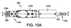
図3~5および9~11を参照すると、脛骨の髄内管に切り込むように構成された電力ドライバ100が開示されている。電力ドライバ100は、手持ち操作用の電力ドライバユニット300と、電力ドライバアダプタ200とを備える。 Referring to FIGS. 3-5 and 9-11, a
好ましくは、電力ドライバユニット300は、電力ドライバアダプタ200を回転可能に駆動することができ、電力ドライバアダプタ200の駆動シャフト222と係合するチャック310を備える、手持ちドリル状の電動工具である。 Preferably, the
図3~5および9~11に示すように、電力ドライバアダプタ200は、第1の端部220、第2の部分230、および長手方向軸線Lを有する細長い本体210を備える。第1の端部220は、駆動端部として構成されており、駆動シャフト222を有する。駆動シャフト222は、長手方向軸線Lと同軸に配置されており、駆動シャフト222を長手方向軸線Lと同軸に回転させる電力ドライバユニット300と係合するように構成されている。第2の部分230は、切削工具ビット受容部として構成される。切削工具ビット受容部230は、切削工具ビット500と係合し、切削動作のために切削工具ビット500を回転させるように構成される。例えば、図10および11に示したように、切削工具ビット受容部230は、切削工具ビット500を受容しかつビットをしっかりと保持するように構成された切削工具ビット受容ベース232を備えることができる。切削工具ビット受容ベース232は、長手方向軸線Lに直交する回転軸Rを中心に回転するように構成される。 As shown in FIGS. 3-5 and 9-11, the
図示の実施形態における切削工具ビット受容ベース232は、切削工具ビット500をねじ込むことができるねじ穴232aを含むディスク状の部品である。切削工具ビット受容ベース232に取り付けるように構成された切削工具ビット500は、ねじ山付きベースステム(図示せず)を備える。いくつかの他の実施形態では、切削工具ビット受容ベース232は、切削工具ビット500を受容する代わりに、ソケット穴を備えることができる。ソケット穴は、正方形の穴構成または六角形の穴構成を有することができ、切削工具ビット500を保持するためのばね式戻り止めシステムを有することができる。これらは単なる例であり、当業者によって容易に理解されるであろう、切削工具ビット受容ベース232を切削工具ビット500と係合させるための他の適切な構成が存在する。 The cutting tool
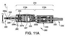
細長い本体210は、第1の部分210aおよび第2の部分210bを含む。細長い本体210は、第1の部分210aにスリップクラッチを備え、第2の部分210bに一連の歯車を備え、歯車は、駆動シャフト222を切削工具ビット受容部230に接続している。一連の歯車は、駆動シャフト222の同軸回転を、切削工具ビット受容ベース232の回転に変換する配列で構成されている。そのような一連の歯車の例は、図11の細長い本体210の断面図に示されている。 The
第1の部分210aは、スリップクラッチ機構223によって駆動シャフト222に接続された駆動シャフト延長部品222aを備える。切削工具ビット受容部分230が第2の部分210bのハウジングに対して下部(開始)または上部(終了)位置に達すると、スリップクラッチ223は、駆動シャフト222が電力ドライバ300によって回転され続けることを可能にする一方、ドライブシャフト延長部品222a(および、ひいては、平歯車227)が回転を停止する。第2の部分210bは、回転運動切削工具ビット受容ベース232に伝達するための平歯車227のグループを含む。平歯車227のグループと、駆動軸222aとの間に、かさ歯車構成225が設けられており、駆動軸222、222aの同軸回転運動を、切断工具ビット受容ベース232の直交向きの回転運動に変換する。 The
いくつかの実施形態では、切削工具ビット受容ベース232は平歯車であり、切削工具受容部分230は、切削工具ビット受容ベース232を平歯車227のグループと接続する1つ以上の追加の平歯車229を備えることができる。切削工具ビット受容ベース232および平歯車227のグループ内の追加の平歯車は、短いまたは低プロファイルを有し、かつディスク状の形状を有し、これにより、切削工具ビット受容部分230は、切除された関節空間22内へ切削工具ビット受容部分230を位置決めするための低プロファイルを維持することができる。平歯車227のグループの中の最後の平歯車227aは、追加の平歯車229の中の最初の平歯車229aと噛み合う。 In some embodiments, the cutting tool
切削工具ビット500は、整形外科手術で使用され得る多くのタイプの切削工具ビットのうちの1つであることができる。電力ドライバアダプタ200のいくつかの実施形態では、切削工具ビット500はリーマビットである。 The
電力ドライバアダプタ200のいくつかの実施形態では、切削工具ビット受容部分230は、切削工具ビット500の回転軸線Rと同軸であり、かつ長手方向軸線Lに直交する方向に沿って直線的に並進するように構成することができる。線形並進運動の方向は、図11に矢印T1およびT2によって示されている。図11の図は、側方から見た断面図である。したがって、電力ドライバアダプタ200が切除された関節空間22において動作中に使用されているとき、矢印T1は解剖学的上方向を表し、矢印T2は解剖学的下方向を表す。 In some embodiments of the
いくつかの実施形態では、平歯車227のグループに加えて、第2の部分210bは、切削工具ビット受容部分230の直線並進を可能にするらせん状ねじ山配列をさらに含む。図11に示す例示的な構造では、このらせん状ねじ山配置は、らせん状ねじ山付きステム240と、切削工具ビット受容部分230内の追加の平歯車229のうちの第1の平歯車229aとを含む。第1の平歯車229aは、その回転中心にらせん状ねじ穴を備え、これは、らせん状ねじ穴を通って延びるらせんねじ山付きステム240と係合する。らせん状ねじ山付きステム240は回転しない。切削工具ビット500が切削動作のために回転しているとき、第1の平歯車229aが回転すると、そのらせん状ねじ穴は、らせん状ねじ山付きステム240のらせん状ねじ山と協働し、らせん状ねじ山付きステム240の長さに沿って並進し、これにより切削工具ビット受容部分230全体をらせん状ねじ山付きステム240の長さに沿って移動させる。 In some embodiments, in addition to the group of spur gears 227, the
回転方向に応じて、第1の平歯車229aのらせん状ねじ山およびらせん状ねじ山付きステム240は、適切にハンドされ(右ハンドまたは左ハンド)、これにより、第1の平歯車229a、したがって切削工具ビット受容部分230が、切断工具ビット500が切断方向に回転または駆動されたとき図11に矢印によって示された方向T2に並進する。逆に、切断手順が完了すると、動力駆動ユニット300が逆になり、切削工具ビット500が反対方向に回転し、第1の平歯車229aおよび切削工具受容部分230が、らせん状ねじ山付きステム240に沿って反対方向T1に並進する。 Depending on the direction of rotation, the spiral thread and the spiral threaded
電力ドライバアダプタ200が、脛骨の遠位端をリーミングするために使用される場合、例えば、電力ドライバアダプタ200が、切削工具ビット500が脛骨の髄内管に向けられて配置されるような位置にある場合、切削工具受容部分230は、開始位置、すなわち切削工具受容部分230が最も下方の位置にあるような位置にある。この開始構成が、図11Bに示されている。図11Bでは、切削工具受容部分230は、位置合わせピン260の反対側にあるので、開始位置にあることがわかる。位置合わせピン260の機能は、図3~5に関連して以下に説明される。電力ドライバユニット300がその切断モードになると、切削工具ビット500が切削方向に回転すると、切削工具保持部分230が方向T2に並進する。これにより、電力ドライバユニット300全体および電力ドライバアダプタ200を動かすことなく、切削工具ビット500を脛骨の髄内管内へ駆動することができる。電力ドライバユニット300および電力ドライバアダプタ200アセンブリが静止状態に保たれている間、切削工具ビット500は、切削工具ビット受容部分230の並進運動によって自動的に髄内管内へ駆動される。 When the
図3、4、および6を参照すると、いくつかの実施形態では、電力ドライバアダプタ200は、ガイドアセンブリ400に関連して使用することができ、ガイドアセンブリ400は、脛骨の髄内管を準備する手順の間、切除された関節空間22内での電力ドライバアダプタ200の位置決めおよび位置合わせを支援することができる。ガイドアセンブリ400は、脛骨の遠位端において切除面に取り付けるように構成されたガイド部分410を含み、ガイド部分は、切削工具ビット500を受容し、通過させることを可能にするための穴430を備える。ガイドアセンブリ400はまた、ガイド部分410から近位方向に延在し、図6に示されるように脛骨の前側に取り付けるように構成されたガイドヘッド部分420を含む。 Referring to FIGS. 3, 4, and 6, in some embodiments, the
電力ドライバアダプタ200およびガイドヘッド部分420は、脛骨の髄内管に切り込むために、電力ドライバアダプタ200に保持された切削工具ビット500を適切に位置合わせおよび配置するように構成されている。電力ドライバアダプタ200は、1つ以上の位置合わせピンを備えることができ、ガイドヘッド部分420は、電力ドライバアダプタ200の位置を位置合わせするための位置合わせピンを受容するための1つ以上の対応する位置合わせスロットを含むことができる。 The
図4~6に示される例示的な実施形態では、電力ドライバアダプタ200は2つの位置合わせピン260を含み、ガイドヘッド部分420は、位置合わせピン260を受容するための対応する2つの位置合わせスロット440を備える。電力ドライバアダプタ200の切削工具ビット受容部分230を前側から関節空間22に挿入した後、2つの位置合わせピン260が、ガイドヘッド部分420の対応する位置合わせスロット440に挿入される。電力ドライバアダプタ200は、切削工具ビット500が切削工具ビット受容部分230内に保持されて、脛骨の髄内管に向けられた切除された脛骨の遠位端に配置され、脛骨の髄内管に切り込む準備ができるように配向される。いくつかの実施形態では、位置合わせスロット440は、位置合わせピン260および位置合わせスロット440がスリップフィット係合を確立するように成形およびサイズ設定され、これは、切断手順中に電力ドライバアダプタ200アセンブリを所定の位置にしっかりと保持するのを助けることができる。この配置は、図3および4が実際に脛骨髄内管準備手順の最後の配置を示しているという事実を除いて、図3および4に示されているものと非常によく似ている。 In the exemplary embodiment shown in FIGS. 4-6, the
使用中、ガイドアセンブリ400が、図6に示されるように切除された関節空間22に配置された後、ガイドアセンブリ400は、kワイヤまたはスタインマンピンなどの1つ以上の固定ピンを使用することによって脛骨に固定することができる。ガイドヘッド部分420は、そのような固定ピンを受容するためにガイドヘッド部分420を貫通した1つ以上の穴を備えることができる。図6に示す例では、ガイドヘッド部分420に複数の穴450が設けられている。固定ピン600が、これらの穴450に挿入され、ガイドアセンブリ400を脛骨6に固定していることが示されている。 In use, after the
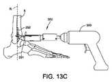
いくつかの実施形態では、電力ドライバアダプタ200は、位置合わせガイド400を使用せずに、関節空間22内で位置合わせすることができる。例えば、電力ドライバアダプタ200は、図13A~13Cに示されるもののような位置合わせアーム290で構成することができ、位置合わせアーム290および位置合わせピン292は放射線不透過性である。電力ドライバアダプタ200は、関節空間22に挿入され、透視下で観察されて、切削工具ビット500を位置合わせする。いくつかの実施形態では、電力ドライバアダプタ200は、放射線透過性材料で作ることができ、位置合わせの手がかりのために放射線不透過性マーカー(例えば、標的)を備えることができる。 In some embodiments, the
本開示の別の態様によれば、手術器具キットが開示される。手術器具キットは、脛骨の髄内管に切り込むように構成された電力ドライバアダプタ200、および1つ以上の骨切断工具ビット(例えば、1つ以上のリーミングビット500)を含む。電力ドライバアダプタ200の構造は上記の通りである。いくつかの実施形態では、手術器具キットはまた、その構造が上記の通りであるガイドアセンブリ400を含むことができる。 According to another aspect of the present disclosure, a surgical instrument kit is disclosed. The surgical instrument kit includes a
本開示の別の態様によれば、脛骨インプラントを受容するために脛骨において髄内管を準備するためのいくつかの方法が開示されている。いくつかの実施形態によれば、図13A~13Cに関連した図12Aのフローチャート1000aは、このような方法の一例を示しており、この場合、切削工具ビット500を備えた電力ドライバアダプタ200が、一実施形態による脛骨インプラントを受容するために脛骨の遠位端に髄内管を準備するために、足関節の切断された関節空間22に前側からアプローチする。この方法は、脛骨の遠位端を切除し、脛骨インプラントを受容するための切除された関節空間22を形成することを含み、関節空間は、脛骨の遠位端に脛骨切除面を含み、前側で開放している(ステップ1010を参照)。必要に応じて、切除された関節空間22を適切に形成するために、距骨の近位端も切除する必要がある場合がある。次に、切削工具ビット500を備えた電力ドライバアダプタ200を備えた電力ドライバユニット300が、前側から関節空間22内に配置され、切削工具ビット500は、脛骨の髄内管に向けられる(ステップ1020を参照)。次に、電力ドライバユニット300がオンにされ、切削工具ビット500を駆動して髄内管に切り込む(ステップ1030を参照)。 According to another aspect of the present disclosure, several methods for preparing an intramedullary canal in the tibia to receive a tibial implant are disclosed. According to some embodiments, the
この方法のいくつかの実施形態では、髄内管に切り込むことにより、脛骨ステムまたは足関節置換インプラントの脛骨延長部を受容するために、髄内管内に延びる空隙または脛骨腔が形成される。 In some embodiments of this method, cutting into the intramedullary canal creates a void or tibial cavity that extends into the intramedullary canal to receive the tibial extension of the tibial stem or ankle replacement implant.
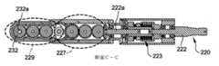
図13A~13Cに示した構成では、一対の位置合わせアーム290を備えた電力ドライバアダプタ200の実施形態が示されている。位置合わせアーム290は、電力ドライバアダプタ200が切除された関節空間22内に配置されるときに、切削工具ビット500の軌道を位置合わせするのを支援する。位置合わせアーム290は、電力ドライバアダプタ200から延在し、前方に湾曲する端部291を有する。位置合わせアーム290は、端部291に設けられた位置合わせポスト292を備え、位置合わせポスト292は、切削工具ビット500の切断軌道を表し、切削手順の前または間に切削工具ビット500の位置合わせ/軌道を維持しながら電力ドライバアダプタ200を視覚的に配置するために使用することができる。図13Aおよび13Cに示されるように、位置合わせアーム290および位置合わせポスト292は、位置合わせポスト292が、切削工具ビット受容ベース232に取り付けられた切削工具ビット500の回転軸線Rに対して平行になりかつ2つの位置合わせポスト292がまた回転軸線Rと同じ平面にあるように構成されている。この構成により、外科医は、位置合わせポスト292を視覚的ガイドとして使用して、電力ドライバアダプタ200を関節空間22に位置合わせすることができる。図13Cの側面図は、位置合わせポスト292をガイドとして使用することにより、切削工具ビットの回転軸線Rが脛骨6の髄内管と位置合わせされた位置合わせ位置にある電力ドライバアダプタ200を示している。 In the configurations shown in FIGS. 13A to 13C, an embodiment of a
図3および図4に関連した図12Bのフローチャート1000bは、ガイドアセンブリ400を使用して切削工具ビット500の軌道を位置合わせする方法の別の実施形態を示している。フローチャート1000bに示した方法は、ステップ1010の後に足関節の前側から関節空間にガイドアセンブリ400を設置するステップ1015をさらに含む。次に、ステップ1020において、切削工具ビット500を備えた電力ドライバアダプタ200を前側から切除関節空間22に配置した後、電力ドライバアダプタ200を前側からガイドアセンブリ400と係合させ、切削工具ビット500の位置を位置合わせする(ステップ1025を参照)。次に、電力ドライバユニット300がオンにされ、切削工具ビット500を駆動して髄内管に切り込み、脛骨インプラントのために髄内管を準備する(ステップ1030を参照)。 The
図7に関連した図12Cのフローチャート2000aは、一実施形態による、脛骨インプラントを受容するために脛骨に髄内管を準備する後側アプローチ方法の例を示している。この方法は、脛骨の遠位端を切除し、脛骨インプラントを受容するための切除された関節空間22を形成することを含み、関節空間は、脛骨の遠位端に脛骨切除面を含み、後側で開放している(ステップ2010を参照)。必要に応じて、切除された関節空間22を適切に形成するために、距骨の近位端も切除する必要がある場合がある。次に、切削工具ビット500を備えた電力ドライバアダプタ200が、後側から関節空間22内に配置され、切削工具ビット500は、脛骨の髄内管に向けられる(ステップ2020を参照)。次に、電力ドライバユニット300がオンにされ、切削工具ビット500を駆動して髄内管に切り込み、脛骨インプラントのために髄内管を準備する(ステップ2030を参照)。
図12Dのフローチャート2000bは、後側アプローチ方法の別の実施形態を示しており、この方法は、ステップ2010の後に足関節の後側から関節空間にガイドアセンブリ400を設置するステップ2015をさらに含む。次に、ステップ2020において、切削工具ビット500を備えた電力ドライバアダプタ200を後側から切除関節空間22に配置した後、電力ドライバアダプタ200を後側からガイドアセンブリ400と係合させ、切削工具ビット500の位置を位置合わせする(ステップ2025を参照)。次に、電力ドライバユニット300がオンにされ、切削工具ビット500を駆動して髄内管に切り込み、脛骨インプラントのために髄内管を準備する(ステップ2030を参照)。 The
図7は、ガイドアセンブリ400が切除された関節空間22内に配置された後の後側アプローチ配置の図である。ガイドヘッド部分420は、ガイドアセンブリ400を後側から脛骨6に固定するための1つ以上の固定ピン600を受容するための複数の穴450を備えている。固定ピン600は、ガイドアセンブリ400を脛骨6に固定する穴450を通して挿入されて示されている。この実施形態では、ガイドアセンブリ400自体は、位置合わせガイドアーム490を含むことができる。位置合わせガイドアーム490は、適切な取り付け機構を介してガイドヘッド部分420に取り付けることができる。図示の例では、ガイドヘッド部分420は、位置合わせガイドアーム490が取り付けられている1つ以上のピン/ねじ422で構成されている。位置合わせガイドアーム490の重要な特徴は、それがガイドヘッド部分420から横方向に延在し、位置合わせポスト492を備えていることである。これにより、操作者/外科医は、脛骨6への取り付け中にガイドアセンブリ400を視覚的に位置合わせすることができ、これにより、切削工具ビット500が適切に位置合わせされることが保証される。次に、切削工具ビット500を備えた電力ドライバアダプタ200が、患者の後側から関節空間22内に配置され、ガイドアセンブリ400と結合される。位置合わせポスト492およびガイドヘッド部分420は、電力ドライバアダプタ200が、位置合わせピン260をガイドヘッド部分420の対応する位置合わせスロット440に滑り込ませることによって、ガイドヘッド部分420と係合および位置合わせされるとき、位置合わせポスト492が、切削工具ビット500の回転軸線Rに対して平行になるように、構成されている。 FIG. 7 is a diagram of the posterior approach arrangement after the
図8に関連した図12Eのフローチャート3000aは、一実施形態による、脛骨インプラントを受容するために脛骨に髄内管を準備する側方アプローチ方法の例を示している。この方法は、脛骨の遠位端、必要であれば、距骨の近位端を切除し、脛骨インプラントを受容するための切除された関節空間22を形成することを含み、関節空間は、脛骨の遠位端に脛骨切除面を含み、側方側で開放している(ステップ3010を参照)。次に、切削工具ビット500を備えた電力ドライバアダプタ200が、側方側から関節空間22内に配置され、切削工具ビット500は、脛骨の髄内管に向けられる(ステップ3020を参照)。次に、電力ドライバユニット300がオンにされ、切削工具ビット500を駆動して髄内管に切り込み、脛骨インプラントのために髄内管を準備する(ステップ3030を参照)。
図12Fのフローチャート1000bは、側方アプローチ方法の別の実施形態を示しており、この方法は、ステップ3010の後に足関節の側方側から関節空間にガイドアセンブリ400を設置するステップ3015をさらに含む。次に、ステップ3020において、切削工具ビット500を備えた電力ドライバアダプタ200を側方側から切除関節空間22に配置した後、電力ドライバアダプタ200を側方側からガイドアセンブリ400と係合させ、切削工具ビット500の位置を位置合わせする(ステップ3025を参照)。次に、電力ドライバユニット300がオンにされ、切削工具ビット500を駆動して髄内管に切り込み、脛骨インプラントのために髄内管を準備する(ステップ3030を参照)。 The
図8は、ガイドアセンブリ400が次に切除された関節空間22内に配置される、側方アプローチ配列の図である。ガイドヘッド部分420は、ガイドアセンブリ400を後側から脛骨6に固定するための1つ以上の固定ピン600を受容するための複数の穴450を備えている。固定ピン600は、ガイドアセンブリ400を脛骨6に固定する穴450を通して挿入されて示されている。次に、切削工具ビット500を備えた電力ドライバアダプタ200が、患者の側方側から関節空間22内に配置され、ガイドアセンブリ400と結合される。図7に関連して上で提供された説明と同様に、側方アプローチ配列のいくつかの実施形態では、ガイドアセンブリ400は、位置合わせポスト492を備えた位置合わせガイドアーム490を含むことができる。この実施形態における位置合わせガイドアーム490および位置合わせポスト492の機能は、図7に示され、説明されている実施形態と同様である。 FIG. 8 is a diagram of a lateral approach arrangement in which the
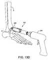
図13Dに関連した図12Gのフローチャート4000aは、一実施形態による、距骨インプラントを受容するために距骨の近位端を準備する前側アプローチ方法の例を示している。この方法は、脛骨の遠位端、必要であれば、距骨の近位端を切除し、切除された関節空間22を形成することを含み、関節空間は、脛骨の遠位端における脛骨切除面、および距骨の近位端における距骨切除面を含み、関節空間22は、前側で開放している(ステップ4010を参照)。次に、切削工具ビット500を備えた電力ドライバアダプタ200が、前側から関節空間22内に配置され、切削工具ビット500は、距骨に向けられる(ステップ4020を参照)。次に、電力ドライバユニット300がオンにされ、切削工具ビット500を駆動して距骨切除面に切り込み、距骨ステムおよび/または距骨インプラント用の増強物を受容するために距骨内に延びる空隙を形成する(ステップ4030を参照)。
図12Hのフローチャート4000bは、一実施形態による、距骨インプラントを受容するために距骨の近位端を準備する後側アプローチ方法の例を示している。この方法は、脛骨の遠位端、必要であれば、距骨の近位端を切除し、切除された関節空間22を形成することを含み、関節空間は、脛骨の遠位端における脛骨切除面、および距骨の近位端における距骨切除面を含み、関節空間22は、後側で開放している(ステップ4010bを参照)。次に、切削工具ビット500を備えた電力ドライバアダプタ200が、後側から関節空間22内に配置され、切削工具ビット500は、距骨に向けられる(ステップ4020bを参照)。次に、電力ドライバユニット300がオンにされ、切削工具ビット500を駆動して距骨切除面に切り込み、距骨ステムおよび/または距骨インプラント用の増強物を受容するために距骨内に延びる空隙を形成する(ステップ4030bを参照)。
図12Iのフローチャート4000cは、一実施形態による、距骨インプラントを受容するために距骨の近位端を準備する側方アプローチ方法の例を示している。この方法は、脛骨の遠位端、必要であれば、距骨の近位端を切除し、切除された関節空間22を形成することを含み、関節空間は、脛骨の遠位端における脛骨切除面、および距骨の近位端における距骨切除面を含み、関節空間22は、側方側で開放している(ステップ4010cを参照)。次に、切削工具ビット500を備えた電力ドライバアダプタ200が、側方側から関節空間22内に配置され、切削工具ビット500は、距骨に向けられる(ステップ4020cを参照)。次に、電力ドライバユニット300がオンにされ、切削工具ビット500を駆動して距骨切除面に切り込み、距骨ステムおよび/または距骨インプラント用の増強物を受容するために距骨内に延びる空隙を形成する(ステップ4030cを参照)。
本明細書に記載の方法の様々な実施形態では、切削工具ビット500を備えた電力ドライバアダプタ200は、脛骨または距骨の切除切断が行われる前に、脛骨と距骨との間の足関節空間に配置することができる。このような例では、適切に構成されたガイドアセンブリジグ(図示せず)を脛骨と距骨の間の関節に挿入することができ、次に、脛骨の遠位端または距骨の近位端に切除切断が行われる前に、電力ドライバアダプタ200の切断ツールビット端部を脛骨と距骨との間にガイドして配置することができる。 In various embodiments of the methods described herein, the
デバイス、キット、システム、および方法は、例示的な実施形態に関して説明されてきたが、それらはそれに限定されない。むしろ、添付の特許請求の範囲は、デバイス、キット、システム、および方法の均等物の範囲およびレンジから逸脱することなく当業者によって成され得る、デバイス、キット、システム、および方法の他の変化形および実施形態を含むように広く解釈されるべきである。 Devices, kits, systems, and methods have been described with respect to exemplary embodiments, but they are not limited thereto. Rather, the claims of attachment may be made by one of ordinary skill in the art without departing from the scope and range of equivalents of devices, kits, systems, and methods, other variants of devices, kits, systems, and methods. And should be broadly interpreted to include embodiments.
Claims (40)
Translated fromJapanesea)前記脛骨の遠位端を切除して、前記脛骨インプラントのための切除された関節空間を形成することであって、前記関節空間は、前記脛骨の前記遠位端に脛骨切除面を含み、前側で開放している、形成することと、
b)切削工具ビットを備えた電力ドライバを前側から前記切除された関節空間に配置することであって、前記切削工具ビットは、前記脛骨の前記髄内管に向けられる、配置することと、
c)前記電力ドライバを使用して前記髄内管に切り込むことと、を含む方法。A method of preparing an intramedullary canal in the tibia to receive a tibial implant, wherein the tibia comprises the distal end and the method is:
a) By excising the distal end of the tibia to form an excised joint space for the tibial implant, the articular space comprises a tibial excision surface at the distal end of the tibia. , Open on the front side, forming and
b) Placing a power driver with a cutting tool bit from the anterior side into the excised joint space, wherein the cutting tool bit is directed toward the intramedullary canal of the tibia.
c) A method comprising cutting into the intramedullary canal using the power driver.
前記ガイドアセンブリを前記前側から前記関節空間に挿入することと、
前記ガイドアセンブリを前記脛骨切除面と同じ高さに位置合わせすることと、
前記ガイドアセンブリを前記脛骨に固定することと、
前記ガイドの位置合わせおよび軌道を確認することと、
ガイドヘッド部分を1つ以上のピンで前記脛骨に固定することと、を含む、請求項2に記載の方法。Installing the guide assembly in the joint space
Inserting the guide assembly into the joint space from the front side and
To align the guide assembly with the tibial resection surface and
Fixing the guide assembly to the tibia and
Checking the alignment and trajectory of the guide,
2. The method of claim 2, comprising fixing the guide head portion to the tibia with one or more pins.
a)前記脛骨の遠位端を切除して、前記脛骨インプラントのための切除された関節空間を形成することであって、前記関節空間は、前記脛骨の前記遠位端に脛骨切除面を含み、後側で開放している、形成することと、
b)切削工具ビットを備えた電力ドライバを前記後側から前記関節空間に配置することであって、前記切削工具ビットは、前記脛骨の前記髄内管に向けられる、配置することと、
c)前記電力ドライバを使用して前記髄内管に切り込むことと、を含む方法。A method of preparing an intramedullary canal in the tibia to receive a tibial implant, wherein the tibia comprises the distal end and the method is:
a) By excising the distal end of the tibia to form an excised joint space for the tibial implant, the articular space comprises a tibial excision surface at the distal end of the tibia. , Opening on the back side, forming and
b) Placing a power driver with a cutting tool bit in the articular space from the posterior side, wherein the cutting tool bit is directed to the intramedullary canal of the tibia.
c) A method comprising cutting into the intramedullary canal using the power driver.
前記ガイドアセンブリを前記後側から前記関節空間に挿入することと、
前記ガイドアセンブリを前記脛骨切除面と同じ高さに位置合わせすることと、
前記ガイドアセンブリを前記脛骨に固定することと、
前記ガイドの位置合わせおよび軌道を確認することと、
ガイドヘッド部分を1つ以上のピンで前記脛骨に固定することと、を含む、請求項6に記載の方法。Installing the guide assembly in the joint space
Inserting the guide assembly into the joint space from the posterior side and
To align the guide assembly with the tibial resection surface and
Fixing the guide assembly to the tibia and
Checking the alignment and trajectory of the guide,
6. The method of claim 6, comprising fixing the guide head portion to the tibia with one or more pins.
a)前記脛骨の遠位端を切除して、前記脛骨インプラントのための切除された関節空間を形成することであって、前記関節空間は、前記脛骨の前記遠位端に脛骨切除面を含み、側方側で開放している、形成することと、
b)切削工具ビットを備えた電力ドライバを前記側方側から前記関節空間に配置することであって、前記切削工具ビットは、前記脛骨の前記髄内管に向けられる、配置することと、
c)前記電力ドライバを使用して前記髄内管に切り込むことと、を含む方法。A method of preparing an intramedullary canal in the tibia to receive a tibial implant, wherein the tibia comprises the distal end and the method is:
a) The distal end of the tibia is excised to form an excised joint space for the tibial implant, wherein the articular space includes a tibial resection surface at the distal end of the tibia. , Open on the side, forming and
b) Placing a power driver with a cutting tool bit in the articular space from the lateral side, wherein the cutting tool bit is directed toward the intramedullary canal of the tibia.
c) A method comprising cutting into the intramedullary canal using the power driver.
前記ガイドアセンブリを前記側方側から前記関節空間に挿入することと、
前記ガイドアセンブリを前記脛骨切除面と同じ高さに位置合わせすることと、
前記ガイドアセンブリを前記脛骨に固定することと、
前記ガイドの位置合わせおよび軌道を確認することと、
ガイドヘッド部分を1つ以上のピンで前記脛骨に固定することと、を含む、請求項10に記載の方法。Installing the guide assembly in the joint space
Inserting the guide assembly into the joint space from the lateral side and
To align the guide assembly with the tibial resection surface and
Fixing the guide assembly to the tibia and
Checking the alignment and trajectory of the guide,
10. The method of claim 10, comprising fixing the guide head portion to the tibia with one or more pins.
脛骨の髄内管に切り込むように構成された電力ドライバアダプタを備え、前記電力ドライバアダプタは、
駆動端部、切削工具ビット受容端部、および長手方向軸線を有する細長い本体であって、
前記駆動端部は、前記長手方向軸線と同軸に配置された駆動シャフトを有し、前記駆動シャフトは、前記駆動シャフトを前記長手方向軸線を中心に同軸に回転させる動力供給ユニットと嵌合するように構成されており、
前記切削工具ビット受容端部は、切削工具ビットと係合するように構成され、かつ切削動作のために前記切削工具ビットを回転させる切削工具ビット受容ベースを含み、前記切削工具ビット受容ベースは、前記細長い本体の前記長手方向軸線に直交する回転軸線を中心に回転し、
前記細長い本体は、前記駆動シャフトを前記切削工具ビット受容端部に接続する一連の歯車を含み、
前記一連の歯車は、前記駆動シャフトの同軸回転を前記切削工具ビット受容ベースの回転に変換する配置で構成されている、細長い本体と、
ガイドアセンブリであって、
前記脛骨の遠位端の切除面に取り付けるように構成されたガイド部分であって、前記ガイド部分は、前記切削工具ビットを受容しかつ前記ガイド部分に貫通させることを可能にするための穴を含む、ガイド部分と、
前記ガイド部分から近位方向に延在し、前記脛骨の前側に取り付けるように構成されたガイドヘッド部分と、を含むガイドアセンブリと、を備える、手術器具キット。Surgical instrument kit
It comprises a power driver adapter configured to cut into the intramedullary canal of the tibia, said power driver adapter.
An elongated body with a drive end, a cutting tool bit receiving end, and a longitudinal axis.
The drive end has a drive shaft coaxially arranged with the longitudinal axis, and the drive shaft is fitted with a power supply unit that rotates the drive shaft coaxially about the longitudinal axis. Is configured in
The cutting tool bit receiving end is configured to engage the cutting tool bit and includes a cutting tool bit receiving base that rotates the cutting tool bit for a cutting operation, the cutting tool bit receiving base. Rotating around the rotation axis orthogonal to the longitudinal axis of the elongated body,
The elongated body comprises a series of gears connecting the drive shaft to the cutting tool bit receiving end.
The series of gears comprises an elongated body and an elongated body configured to convert the coaxial rotation of the drive shaft into the rotation of the cutting tool bit receiving base.
It ’s a guide assembly.
A guide portion configured to attach to the cut surface at the distal end of the tibia, wherein the guide portion provides a hole for receiving the cutting tool bit and allowing it to penetrate the guide portion. Including, guide part,
A surgical instrument kit comprising a guide assembly comprising a guide head portion extending proximally from the guide portion and configured to attach to the anterior side of the tibia.
駆動端部、切削工具ビット受容端部、および長手方向軸線を有する細長い本体を備え、
前記駆動端部は、前記長手方向軸線と同軸に配置された駆動シャフトを有し、前記駆動シャフトは、前記駆動シャフトを前記長手方向軸線を中心に同軸に回転させる動力供給ユニットと嵌合するように構成されており、
前記切削工具ビット受容端部は、切削工具ビットと係合するように構成され、かつ切削動作のために前記切削工具ビットを回転させる切削工具ビット受容ベースを含み、前記切削工具ビット受容ベースは、前記細長い本体の前記長手方向軸線に直交する回転軸線を中心に回転し、
前記細長い本体は、前記駆動シャフトを前記切削工具ビット受容端部に接続する一連の歯車を含み、
前記一連の歯車は、前記駆動シャフトの同軸回転を前記切削工具ビット受容ベースの回転に変換する配置で構成されている、電力ドライバアダプタ。A power driver adapter configured to cut into the intramedullary canal of the tibia, said power driver adapter.
With a drive end, a cutting tool bit receiving end, and an elongated body with a longitudinal axis,
The drive end has a drive shaft coaxially arranged with the longitudinal axis, and the drive shaft is fitted with a power supply unit that rotates the drive shaft coaxially about the longitudinal axis. Is configured in
The cutting tool bit receiving end is configured to engage the cutting tool bit and includes a cutting tool bit receiving base that rotates the cutting tool bit for a cutting operation, the cutting tool bit receiving base. Rotating around the rotation axis orthogonal to the longitudinal axis of the elongated body,
The elongated body comprises a series of gears connecting the drive shaft to the cutting tool bit receiving end.
The series of gears is a power driver adapter configured to convert the coaxial rotation of the drive shaft into the rotation of the cutting tool bit receiving base.
(a)前記距骨の近位端を切除して、前記距骨インプラントのための切除された関節空間を形成することであって、前記関節空間は、前記距骨の前記近位端に距骨切除面を含み、前側で開放している、形成することと、
(b)切削工具ビットを備えた電力ドライバを前側から前記切除された関節空間に配置することであって、前記切削工具ビットは、前記距骨切除面に向けられる、配置することと、
(c)前記電力ドライバを使用して前記距骨切除面に切り込むことと、を含む方法。A method of preparing a talus for receiving a talus implant, wherein the talus includes the proximal end.
(A) The proximal end of the talus is excised to form an excised joint space for the talus implant, wherein the articular space has a talus excision surface at the proximal end of the talus. Including, opening on the front side, forming and
(B) A power driver equipped with a cutting tool bit is arranged from the front side in the excised joint space, and the cutting tool bit is directed toward the talus excision surface.
(C) A method comprising cutting into the talus excision surface using the power driver.
(a)前記距骨の近位端を切除して、前記距骨インプラントのための切除された関節空間を形成することであって、前記関節空間は、前記距骨の前記近位端に距骨切除面を含み、後側で開放している、形成することと、
(b)切削工具ビットを備えた電力ドライバを前記後側から前記切除された関節空間に配置することであって、前記切削工具ビットは、前記距骨切除面に向けられる、配置することと、
(c)前記電力ドライバを使用して前記距骨切除面に切り込むことと、を含む方法。A method of preparing a talus for receiving a talus implant, wherein the talus includes the proximal end.
(A) The proximal end of the talus is excised to form an excised joint space for the talus implant, wherein the articular space has a talus excision surface at the proximal end of the talus. Including, opening on the posterior side, forming and
(B) Placing a power driver with a cutting tool bit in the excised joint space from the posterior side, wherein the cutting tool bit is directed toward the talus excision surface.
(C) A method comprising cutting into the talus excision surface using the power driver.
(a)前記距骨の前記近位端を切除して、前記距骨インプラントのための切除された関節空間を形成することであって、前記関節空間は、前記距骨の前記近位端に距骨切除面を含み、側方側で開放している、形成することと、
(b)切削工具ビットを備えた電力ドライバを前記側方側から前記切除された関節空間に配置することであって、前記切削工具ビットは、前記距骨切除面に向けられる、配置することと、
(c)前記電力ドライバを使用して前記距骨切除面に切り込むことと、を含む方法。A method of preparing a talus for receiving a talus implant, wherein the talus includes the proximal end.
(A) The proximal end of the talus is excised to form an excised joint space for the talus implant, which is the talus excision surface at the proximal end of the talus. Including, opening on the side, forming and
(B) Placing a power driver with a cutting tool bit in the excised joint space from the lateral side, wherein the cutting tool bit is directed toward the talus excision surface.
(C) A method comprising cutting into the talus excision surface using the power driver.
Priority Applications (1)
| Application Number | Priority Date | Filing Date | Title |
|---|---|---|---|
| JP2023024381AJP7507275B2 (en) | 2019-05-29 | 2023-02-20 | Preparing the tibia to receive a tibial implant component of a replacement ankle |
Applications Claiming Priority (3)
| Application Number | Priority Date | Filing Date | Title |
|---|---|---|---|
| US201962853818P | 2019-05-29 | 2019-05-29 | |
| US62/853,818 | 2019-05-29 | ||
| PCT/US2020/015373WO2020242542A1 (en) | 2019-05-29 | 2020-01-28 | Preparing a tibia for receiving tibial implant component of a replacement ankle |
Related Child Applications (1)
| Application Number | Title | Priority Date | Filing Date |
|---|---|---|---|
| JP2023024381ADivisionJP7507275B2 (en) | 2019-05-29 | 2023-02-20 | Preparing the tibia to receive a tibial implant component of a replacement ankle |
Publications (1)
| Publication Number | Publication Date |
|---|---|
| JP2022531871Atrue JP2022531871A (en) | 2022-07-12 |
Family
ID=73553492
Family Applications (2)
| Application Number | Title | Priority Date | Filing Date |
|---|---|---|---|
| JP2021565834APendingJP2022531871A (en) | 2019-05-29 | 2020-01-28 | Preparation of the tibia to receive the tibial implant component of the replacement ankle |
| JP2023024381AActiveJP7507275B2 (en) | 2019-05-29 | 2023-02-20 | Preparing the tibia to receive a tibial implant component of a replacement ankle |
Family Applications After (1)
| Application Number | Title | Priority Date | Filing Date |
|---|---|---|---|
| JP2023024381AActiveJP7507275B2 (en) | 2019-05-29 | 2023-02-20 | Preparing the tibia to receive a tibial implant component of a replacement ankle |
Country Status (6)
| Country | Link |
|---|---|
| US (2) | US12108959B2 (en) |
| EP (1) | EP3975939B1 (en) |
| JP (2) | JP2022531871A (en) |
| AU (1) | AU2020283377B2 (en) |
| CA (1) | CA3129217A1 (en) |
| WO (1) | WO2020242542A1 (en) |
Families Citing this family (6)
| Publication number | Priority date | Publication date | Assignee | Title |
|---|---|---|---|---|
| EP3975939B1 (en) | 2019-05-29 | 2024-11-13 | Wright Medical Technology, Inc. | Device for preparing a tibia for receiving tibial implant component of a replacement ankle |
| WO2021146015A1 (en) | 2020-01-17 | 2021-07-22 | Wright Medical Technology, Inc. | Guidance tools, systems, and methods |
| WO2022182430A1 (en)* | 2021-02-24 | 2022-09-01 | Wright Medical Technology, Inc. | Preparing a tibia for receiving tibial implant component of a replacement ankle |
| US20250017603A1 (en)* | 2023-07-10 | 2025-01-16 | Vilex Llc | Ankle joint system and related methods |
| WO2025085296A1 (en)* | 2023-10-18 | 2025-04-24 | Zimmer, Inc. | Methods, systems and apparatuses for the cutting of bone |
| WO2025174764A1 (en)* | 2024-02-12 | 2025-08-21 | Medshape, Inc. | Instrumentation for preparing an ankle joint and methods of using the same |
Citations (8)
| Publication number | Priority date | Publication date | Assignee | Title |
|---|---|---|---|---|
| WO2005041823A1 (en)* | 2003-10-02 | 2005-05-12 | Concepts In Medicine Iii, Llc | Ankle joint prosthesis |
| US20100262150A1 (en)* | 2009-04-13 | 2010-10-14 | George John Lian | Custom radiographically designed cutting guides and instruments for use in total ankle replacement surgery |
| WO2012151589A1 (en)* | 2011-05-05 | 2012-11-08 | Wright Medical Technology, Inc. | Orthopedic surgical guide |
| JP2012527285A (en)* | 2009-05-18 | 2012-11-08 | ビーダーマン・モテーク・ゲゼルシャフト・ミット・ベシュレンクテル・ハフツング・ウント・コンパニー・コマンディートゲゼルシャフト | Device for inserting arcuate nails into bone |
| US20140188236A1 (en)* | 2012-12-27 | 2014-07-03 | Wright Medical Technology, Inc. | Ankle replacement system and method |
| US20150134071A1 (en)* | 2013-03-14 | 2015-05-14 | Wright Medical Technology, Inc. | Intramedullary ankle technique and system |
| JP2018149333A (en)* | 2012-12-27 | 2018-09-27 | ライト メディカル テクノロジー インコーポレイテッドWright Medical Technology, Inc. | System and method for artificial ankle joint replacement |
| WO2019009891A1 (en)* | 2017-07-05 | 2019-01-10 | Wright Medical Technology, Inc. | Anterior ankle appoach system and method |
Family Cites Families (478)
| Publication number | Priority date | Publication date | Assignee | Title |
|---|---|---|---|---|
| US3314420A (en) | 1961-10-23 | 1967-04-18 | Haeger Potteries Inc | Prosthetic parts and methods of making the same |
| US3605123A (en) | 1969-04-29 | 1971-09-20 | Melpar Inc | Bone implant |
| CA962806A (en) | 1970-06-04 | 1975-02-18 | Ontario Research Foundation | Surgical prosthetic device |
| US3938198A (en) | 1970-08-04 | 1976-02-17 | Cutter Laboratories, Inc. | Hip joint prosthesis |
| US3708883A (en) | 1971-01-04 | 1973-01-09 | S Flander | Dental implant and method for using the same |
| US3798679A (en) | 1971-07-09 | 1974-03-26 | Ewald Frederick | Joint prostheses |
| US3808606A (en) | 1972-02-22 | 1974-05-07 | R Tronzo | Bone implant with porous exterior surface |
| DE2306552B2 (en) | 1973-02-10 | 1975-07-03 | Friedrichsfeld Gmbh Steinzeug- Und Kunststoffwerke, 6800 Mannheim | Joint endoprosthesis |
| US3843975A (en) | 1973-04-09 | 1974-10-29 | R Tronzo | Prosthesis for femoral shaft |
| DE2340546A1 (en) | 1973-08-10 | 1975-02-27 | Pfaudler Werke Ag | METALLIC IMPLANT AND PROCEDURE FOR ITS MANUFACTURING |
| US4085466A (en) | 1974-11-18 | 1978-04-25 | National Research Development Corporation | Prosthetic joint device |
| US4055862A (en) | 1976-01-23 | 1977-11-01 | Zimmer Usa, Inc. | Human body implant of graphitic carbon fiber reinforced ultra-high molecular weight polyethylene |
| US4052753A (en) | 1976-08-02 | 1977-10-11 | Dedo Richard G | Knee spacer and method of reforming sliding body surfaces |
| US4098626A (en) | 1976-11-15 | 1978-07-04 | Thiokol Corporation | Hydroxy terminated polybutadiene based polyurethane bound propellant grains |
| US4203444A (en) | 1977-11-07 | 1980-05-20 | Dyonics, Inc. | Surgical instrument suitable for closed surgery such as of the knee |
| US4213816A (en) | 1978-06-12 | 1980-07-22 | Glasrock Products, Inc. | Method for bonding porous coating to rigid structural member |
| US4340978A (en) | 1979-07-02 | 1982-07-27 | Biomedical Engineering Corp. | New Jersey meniscal bearing knee replacement |
| US4368040A (en) | 1981-06-01 | 1983-01-11 | Ipco Corporation | Dental impression tray for forming a dental prosthesis in situ |
| US4502161A (en) | 1981-09-21 | 1985-03-05 | Wall W H | Prosthetic meniscus for the repair of joints |
| DE3213434C1 (en) | 1982-04-10 | 1983-10-27 | Günther Dr.med. 7400 Tübingen Aldinger | Process for the production of individually designed endoprostheses or implants |
| US4436684A (en) | 1982-06-03 | 1984-03-13 | Contour Med Partners, Ltd. | Method of forming implantable prostheses for reconstructive surgery |
| US4501266A (en) | 1983-03-04 | 1985-02-26 | Biomet, Inc. | Knee distraction device |
| US4601290A (en) | 1983-10-11 | 1986-07-22 | Cabot Medical Corporation | Surgical instrument for cutting body tissue from a body area having a restricted space |
| US4578806A (en) | 1983-12-15 | 1986-03-25 | General Electric Company | Device for aligning cooperating X-ray systems |
| DE8406730U1 (en) | 1984-03-05 | 1984-04-26 | Waldemar Link (Gmbh & Co), 2000 Hamburg | Surgical chisel |
| US4609551A (en) | 1984-03-20 | 1986-09-02 | Arnold Caplan | Process of and material for stimulating growth of cartilage and bony tissue at anatomical sites |
| US4594380A (en) | 1985-05-01 | 1986-06-10 | At&T Bell Laboratories | Elastomeric controlled release formulation and article comprising same |
| DE3516743A1 (en) | 1985-05-09 | 1986-11-13 | orthoplant Endoprothetik GmbH, 2800 Bremen | Endoprosthesis for a femoral head |
| US4627853A (en) | 1985-05-29 | 1986-12-09 | American Hospital Supply Corporation | Method of producing prostheses for replacement of articular cartilage and prostheses so produced |
| US4680994A (en)* | 1985-06-20 | 1987-07-21 | Sidewinder Products Corporation | Socket wrench with reversing ratchet |
| US4715860A (en) | 1985-08-23 | 1987-12-29 | The Regents Of The University Of California | Porous acetabular hip resurfacing |
| DE3535112A1 (en) | 1985-10-02 | 1987-04-16 | Witzel Ulrich | TIBI PLATE PART OF A KNEE-KNEE ENDOPROTHESIS |
| FR2589720A1 (en) | 1985-11-14 | 1987-05-15 | Aubaniac Jean | KNEE JOINT PROSTHETIC ASSEMBLY |
| US4721104A (en) | 1985-12-02 | 1988-01-26 | Dow Corning Wright Corporation | Femoral surface shaping apparatus for posterior-stabilized knee implants |
| US4703751A (en) | 1986-03-27 | 1987-11-03 | Pohl Kenneth P | Method and apparatus for resecting a distal femoral surface |
| DE8611697U1 (en) | 1986-04-25 | 1986-06-19 | Mecron Medizinische Produkte Gmbh, 1000 Berlin | Kit for a stem prosthesis |
| US4936862A (en) | 1986-05-30 | 1990-06-26 | Walker Peter S | Method of designing and manufacturing a human joint prosthesis |
| US4759350A (en) | 1986-10-17 | 1988-07-26 | Dunn Harold K | Instruments for shaping distal femoral and proximal tibial surfaces |
| US4769040A (en) | 1986-11-18 | 1988-09-06 | Queen's University At Kingston | Tibial prosthesis |
| US5041138A (en) | 1986-11-20 | 1991-08-20 | Massachusetts Institute Of Technology | Neomorphogenesis of cartilage in vivo from cell culture |
| US5002547A (en) | 1987-02-07 | 1991-03-26 | Pfizer Hospital Products Group, Inc. | Apparatus for knee prosthesis |
| US5250050A (en) | 1987-02-07 | 1993-10-05 | Pfizer Hospital Products Group, Inc. | Apparatus for knee prosthesis |
| US4841975A (en) | 1987-04-15 | 1989-06-27 | Cemax, Inc. | Preoperative planning of bone cuts and joint replacement using radiant energy scan imaging |
| US4846835A (en) | 1987-06-15 | 1989-07-11 | Grande Daniel A | Technique for healing lesions in cartilage |
| US5681353A (en) | 1987-07-20 | 1997-10-28 | Regen Biologics, Inc. | Meniscal augmentation device |
| US4880429A (en) | 1987-07-20 | 1989-11-14 | Stone Kevin R | Prosthetic meniscus |
| US5306311A (en) | 1987-07-20 | 1994-04-26 | Regen Corporation | Prosthetic articular cartilage |
| US5007934A (en) | 1987-07-20 | 1991-04-16 | Regen Corporation | Prosthetic meniscus |
| US5303148A (en) | 1987-11-27 | 1994-04-12 | Picker International, Inc. | Voice actuated volume image controller and display controller |
| GB8802671D0 (en) | 1988-02-05 | 1988-03-02 | Goodfellow J W | Orthopaedic joint components tools & methods |
| US4979949A (en) | 1988-04-26 | 1990-12-25 | The Board Of Regents Of The University Of Washington | Robot-aided system for surgery |
| US5162430A (en) | 1988-11-21 | 1992-11-10 | Collagen Corporation | Collagen-polymer conjugates |
| JP2534764B2 (en) | 1989-01-10 | 1996-09-18 | 株式会社東芝 | Shock wave therapy device |
| CH677442A5 (en) | 1989-03-02 | 1991-05-31 | Sulzer Ag | |
| GB8920697D0 (en) | 1989-09-13 | 1989-10-25 | Isis Innovation | Apparatus and method for aligning drilling apparatus in surgical procedures |
| US5234433A (en) | 1989-09-26 | 1993-08-10 | Kirschner Medical Corporation | Method and instrumentation for unicompartmental total knee arthroplasty |
| US5122144A (en) | 1989-09-26 | 1992-06-16 | Kirschner Medical Corporation | Method and instrumentation for unicompartmental total knee arthroplasty |
| US5059216A (en) | 1989-09-29 | 1991-10-22 | Winters Thomas F | Knee joint replacement apparatus |
| EP0528080A1 (en) | 1989-12-13 | 1993-02-24 | Stryker Corporation | Articular cartilage repair piece |
| US5067964A (en) | 1989-12-13 | 1991-11-26 | Stryker Corporation | Articular surface repair |
| US5129908A (en) | 1990-01-23 | 1992-07-14 | Petersen Thomas D | Method and instruments for resection of the patella |
| US5171322A (en) | 1990-02-13 | 1992-12-15 | Kenny Charles H | Stabilized meniscus prosthesis |
| US5063918A (en) | 1990-05-14 | 1991-11-12 | Guhl James F | Multi-mode distraction system for ankle arthroscopy |
| US5523843A (en) | 1990-07-09 | 1996-06-04 | Canon Kabushiki Kaisha | Position detecting system |
| US5226914A (en) | 1990-11-16 | 1993-07-13 | Caplan Arnold I | Method for treating connective tissue disorders |
| US5197985A (en) | 1990-11-16 | 1993-03-30 | Caplan Arnold I | Method for enhancing the implantation and differentiation of marrow-derived mesenchymal cells |
| US6006126A (en) | 1991-01-28 | 1999-12-21 | Cosman; Eric R. | System and method for stereotactic registration of image scan data |
| US5206023A (en) | 1991-01-31 | 1993-04-27 | Robert F. Shaw | Method and compositions for the treatment and repair of defects or lesions in cartilage |
| US5853746A (en) | 1991-01-31 | 1998-12-29 | Robert Francis Shaw | Methods and compositions for the treatment and repair of defects or lesions in cartilage or bone using functional barrier |
| GB9102348D0 (en) | 1991-02-04 | 1991-03-20 | Inst Of Orthopaedics The | Prosthesis for knee replacement |
| CA2041532C (en) | 1991-04-30 | 2002-01-01 | Hamdy Khalil | Urethane sealant having improved sag properties |
| US5108442A (en) | 1991-05-09 | 1992-04-28 | Boehringer Mannheim Corporation | Prosthetic implant locking assembly |
| US5133759A (en) | 1991-05-24 | 1992-07-28 | Turner Richard H | Asymmetrical femoral condye total knee arthroplasty prosthesis |
| US5270300A (en) | 1991-09-06 | 1993-12-14 | Robert Francis Shaw | Methods and compositions for the treatment and repair of defects or lesions in cartilage or bone |
| GB2261672A (en) | 1991-11-18 | 1993-05-26 | Michael Braden | The use of biomaterials for tissue repair |
| US5344459A (en) | 1991-12-03 | 1994-09-06 | Swartz Stephen J | Arthroscopically implantable prosthesis |
| US5383939A (en) | 1991-12-05 | 1995-01-24 | James; Kelvin B. | System for controlling artificial knee joint action in an above knee prosthesis |
| DE4202717C1 (en) | 1991-12-11 | 1993-06-17 | Dietmar Prof. Dr. 3350 Kreiensen De Kubein-Meesenburg | |
| US5344423A (en) | 1992-02-06 | 1994-09-06 | Zimmer, Inc. | Apparatus and method for milling bone |
| GB9202561D0 (en) | 1992-02-07 | 1992-03-25 | Howmedica | Orthopaedic instrument |
| US5520695A (en) | 1992-02-14 | 1996-05-28 | Johnson & Johnson Professional, Inc. | Instruments for use in knee replacement surgery |
| US5258032A (en) | 1992-04-03 | 1993-11-02 | Bertin Kim C | Knee prosthesis provisional apparatus and resection guide and method of use in knee replacement surgery |
| US5503162A (en) | 1992-04-21 | 1996-04-02 | Board Of Regents, University Of Texas System | Arthroscopic cartilage evaluator and method for using the same |
| US5824083A (en) | 1992-04-24 | 1998-10-20 | Draenert; Klaus | Cement-free femoral prosthesis component and method of producing it |
| DE4213597A1 (en) | 1992-04-24 | 1993-10-28 | Klaus Draenert | Femoral prosthesis component to be anchored with bone cement and process for its production |
| US5365996A (en) | 1992-06-10 | 1994-11-22 | Amei Technologies Inc. | Method and apparatus for making customized fixation devices |
| DE4219939C2 (en) | 1992-06-18 | 1995-10-19 | Klaus Dipl Ing Radermacher | Device for aligning, positioning and guiding machining tools, machining or measuring devices for machining a bony structure and method for producing this device |
| CA2098081A1 (en) | 1992-08-13 | 1994-02-14 | Terry L. Dietz | Alignment guide and method |
| US5370692A (en) | 1992-08-14 | 1994-12-06 | Guild Associates, Inc. | Rapid, customized bone prosthesis |
| US5478739A (en) | 1992-10-23 | 1995-12-26 | Advanced Tissue Sciences, Inc. | Three-dimensional stromal cell and tissue culture system |
| WO1994010914A1 (en) | 1992-11-16 | 1994-05-26 | Wright Medical Technology, Inc. | System and method for profiling a patella |
| ATE181814T1 (en) | 1992-11-20 | 1999-07-15 | Sulzer Orthopaedie Ag | BODY FOR DISTRIBUTING BONE CEMENT FOR ANCHORING IMPLANTS |
| US5360446A (en) | 1992-12-18 | 1994-11-01 | Zimmer, Inc. | Interactive prosthesis design system for implantable prosthesis |
| US5728162A (en) | 1993-01-28 | 1998-03-17 | Board Of Regents Of University Of Colorado | Asymmetric condylar and trochlear femoral knee component |
| US5387216A (en) | 1993-02-18 | 1995-02-07 | Thornhill; Thomas S. | Intramedullary based instrument systems for total knee revision |
| US6001895A (en) | 1993-03-22 | 1999-12-14 | Johnson & Johnson Medical, Inc. | Composite surgical material |
| US5724970A (en) | 1993-04-06 | 1998-03-10 | Fonar Corporation | Multipositional MRI for kinematic studies of movable joints |
| CA2126627C (en) | 1993-07-06 | 2005-01-25 | Kim C. Bertin | Femoral milling instrumentation for use in total knee arthroplasty with optional cutting guide attachment |
| US5474559A (en) | 1993-07-06 | 1995-12-12 | Zimmer, Inc. | Femoral milling instrumentation for use in total knee arthroplasty with optional cutting guide attachment |
| DE4341367C1 (en) | 1993-12-04 | 1995-06-14 | Harald Dr Med Dr Med Eufinger | Process for the production of endoprostheses |
| WO1995020362A1 (en) | 1994-01-26 | 1995-08-03 | Reiley Mark A | Improved inflatable device for use in surgical protocol relating to fixation of bone |
| US5885298A (en) | 1994-02-23 | 1999-03-23 | Biomet, Inc. | Patellar clamp and reamer with adjustable stop |
| GB9407153D0 (en) | 1994-04-11 | 1994-06-01 | Corin Medical Ltd | Unicompartmental knee prosthesis |
| BE1008372A3 (en) | 1994-04-19 | 1996-04-02 | Materialise Nv | METHOD FOR MANUFACTURING A perfected MEDICAL MODEL BASED ON DIGITAL IMAGE INFORMATION OF A BODY. |
| FR2719466B1 (en) | 1994-05-04 | 1997-06-06 | Ysebaert Sa | Knee prosthesis with movable meniscus. |
| US5723331A (en) | 1994-05-05 | 1998-03-03 | Genzyme Corporation | Methods and compositions for the repair of articular cartilage defects in mammals |
| US5888220A (en) | 1994-05-06 | 1999-03-30 | Advanced Bio Surfaces, Inc. | Articulating joint repair |
| US5616146A (en) | 1994-05-16 | 1997-04-01 | Murray; William M. | Method and apparatus for machining bone to fit an orthopedic surgical implant |
| GB9413607D0 (en) | 1994-07-06 | 1994-08-24 | Goodfellow John W | Endoprosthetic knee joint device |
| FR2722392A1 (en) | 1994-07-12 | 1996-01-19 | Biomicron | APPARATUS FOR RESECTING KNEE CONDYLES FOR PLACING A PROSTHESIS AND METHOD FOR PLACING SUCH AN APPARATUS |
| US5769899A (en) | 1994-08-12 | 1998-06-23 | Matrix Biotechnologies, Inc. | Cartilage repair unit |
| US5632745A (en) | 1995-02-07 | 1997-05-27 | R&D Biologicals, Inc. | Surgical implantation of cartilage repair unit |
| US5810827A (en) | 1994-09-02 | 1998-09-22 | Hudson Surgical Design, Inc. | Method and apparatus for bony material removal |
| US5597379A (en) | 1994-09-02 | 1997-01-28 | Hudson Surgical Design, Inc. | Method and apparatus for femoral resection alignment |
| US6695848B2 (en) | 1994-09-02 | 2004-02-24 | Hudson Surgical Design, Inc. | Methods for femoral and tibial resection |
| DE4434539C2 (en) | 1994-09-27 | 1998-06-04 | Luis Dr Med Schuster | Process for the production of an endoprosthesis as a joint replacement for knee joints |
| CH690021A5 (en) | 1994-09-28 | 2000-03-31 | Precifar Sa | Cutter holder and cutter set for surgery. |
| US5765561A (en) | 1994-10-07 | 1998-06-16 | Medical Media Systems | Video-based surgical targeting system |
| CA2160198C (en) | 1994-10-27 | 2003-12-30 | Michael J. Pappas | Prosthesis fixturing device |
| DE69526977T2 (en) | 1994-10-28 | 2003-01-23 | Lasersight Technologies, Inc. | MULTI-CAMERA DEVICE FOR EXAMINATION OF THE CORNEA |
| US5578037A (en) | 1994-11-14 | 1996-11-26 | Johnson & Johnson Professional, Inc. | Surgical guide for femoral resection |
| US5630820A (en) | 1994-12-05 | 1997-05-20 | Sulzer Orthopedics Inc. | Surgical bicompartmental tensiometer for revision knee surgery |
| JP3490520B2 (en) | 1994-12-12 | 2004-01-26 | 株式会社ニデック | Ophthalmic equipment |
| US5910143A (en) | 1994-12-16 | 1999-06-08 | Exactech, Inc. | Intramedullary alignment guide tool |
| JP3419931B2 (en) | 1994-12-26 | 2003-06-23 | 京セラ株式会社 | Artificial knee joint |
| US5540696A (en) | 1995-01-06 | 1996-07-30 | Zimmer, Inc. | Instrumentation for use in orthopaedic surgery |
| DE19501069A1 (en) | 1995-01-16 | 1996-07-18 | Wolfgang Kloess | Light sighting device for marking guide path of instrument, esp. diagnostic or therapeutic needle |
| US5749874A (en) | 1995-02-07 | 1998-05-12 | Matrix Biotechnologies, Inc. | Cartilage repair unit and method of assembling same |
| US5575793A (en) | 1995-02-15 | 1996-11-19 | Smith & Nephew Richards Inc. | Patella clamp apparatus |
| US5593450A (en) | 1995-02-27 | 1997-01-14 | Johnson & Johnson Professional, Inc. | Oval domed shaped patella prosthesis |
| US5683468A (en) | 1995-03-13 | 1997-11-04 | Pappas; Michael J. | Mobile bearing total joint replacement |
| US5906934A (en) | 1995-03-14 | 1999-05-25 | Morphogen Pharmaceuticals, Inc. | Mesenchymal stem cells for cartilage repair |
| US5900245A (en) | 1996-03-22 | 1999-05-04 | Focal, Inc. | Compliant tissue sealants |
| EP0738504B1 (en) | 1995-04-20 | 2000-03-22 | Sulzer Orthopädie AG | Tibial tray for a knee joint prosthesis |
| US5542947A (en) | 1995-05-12 | 1996-08-06 | Huwmedica Inc. | Slotted patella resection guide and stylus |
| US6132463A (en) | 1995-05-19 | 2000-10-17 | Etex Corporation | Cell seeding of ceramic compositions |
| US6077270A (en) | 1995-05-31 | 2000-06-20 | Katz; Lawrence | Method and apparatus for locating bone cuts at the distal condylar femur region to receive a femoral prothesis and to coordinate tibial and patellar resection and replacement with femoral resection and replacement |
| US6046379A (en) | 1995-06-07 | 2000-04-04 | Stone; Kevin R. | Meniscal xenografts |
| US5865849A (en) | 1995-06-07 | 1999-02-02 | Crosscart, Inc. | Meniscal heterografts |
| DE69619526T2 (en) | 1995-06-12 | 2002-10-31 | Yeda Research And Development Co., Ltd. | FGF9 AS A SPECIFIC LIGAND FOR FGFR3 |
| US5613970A (en) | 1995-07-06 | 1997-03-25 | Zimmer, Inc. | Orthopaedic instrumentation assembly having an offset bushing |
| US5649929A (en) | 1995-07-10 | 1997-07-22 | Callaway; George Hadley | Knee joint flexion-gap distraction device |
| US5968051A (en) | 1995-07-27 | 1999-10-19 | Johnson & Johnson Professional, Inc. | Patella clamping device |
| US5671741A (en) | 1995-08-04 | 1997-09-30 | The Regents Of The University Of California | Magnetic resonance imaging technique for tissue characterization |
| FR2737967B1 (en) | 1995-08-24 | 1997-11-28 | Benoist Girard & Cie | KNEE PROSTHESIS CORRECTION APPARATUS |
| US5601563A (en) | 1995-08-25 | 1997-02-11 | Zimmer, Inc. | Orthopaedic milling template with attachable cutting guide |
| US20020143402A1 (en) | 1995-09-04 | 2002-10-03 | Limber Ltd. | Hip joint prostheses |
| US5871546A (en) | 1995-09-29 | 1999-02-16 | Johnson & Johnson Professional, Inc. | Femoral component condyle design for knee prosthesis |
| GB2306653B (en) | 1995-10-23 | 1999-12-15 | Finsbury | Surgical tool |
| US5716361A (en) | 1995-11-02 | 1998-02-10 | Masini; Michael A. | Bone cutting guides for use in the implantation of prosthetic joint components |
| US5682886A (en) | 1995-12-26 | 1997-11-04 | Musculographics Inc | Computer-assisted surgical system |
| US6200606B1 (en) | 1996-01-16 | 2001-03-13 | Depuy Orthopaedics, Inc. | Isolation of precursor cells from hematopoietic and nonhematopoietic tissues and their use in vivo bone and cartilage regeneration |
| CA2168283A1 (en) | 1996-01-29 | 1997-07-30 | John Michael Lee | Preparation of biological material for implants |
| JP2965137B2 (en) | 1996-02-02 | 1999-10-18 | 瑞穂医科工業株式会社 | Artificial knee joint |
| US5842477A (en) | 1996-02-21 | 1998-12-01 | Advanced Tissue Sciences, Inc. | Method for repairing cartilage |
| US6352558B1 (en) | 1996-02-22 | 2002-03-05 | Ed. Geistlich Soehne Ag Fuer Chemische Industrie | Method for promoting regeneration of surface cartilage in a damage joint |
| HU219444B (en) | 1996-02-26 | 2001-04-28 | Gábor Krakovits | Sliding surface for knee-joint prothesis |
| US5683466A (en) | 1996-03-26 | 1997-11-04 | Vitale; Glenn C. | Joint surface replacement system |
| CA2201057C (en) | 1996-03-29 | 2002-01-01 | Kenji Morimoto | A method of processing a sectional image of a sample bone including a cortical bone portion and a cancellous bone portion |
| US6299905B1 (en) | 1996-04-16 | 2001-10-09 | Depuy Orthopaedics, Inc. | Bioerodable polymeric adhesives for tissue repair |
| GB9611059D0 (en) | 1996-05-28 | 1996-07-31 | Howmedica | Tibial element for a replacement knee prosthesis |
| GB9611074D0 (en) | 1996-05-28 | 1996-07-31 | Howmedica | Surgical apparatus |
| US5939323A (en) | 1996-05-28 | 1999-08-17 | Brown University | Hyaluronan based biodegradable scaffolds for tissue repair |
| US5779710A (en) | 1996-06-21 | 1998-07-14 | Matsen, Iii; Frederick A. | Joint replacement method and apparatus |
| US6126690A (en) | 1996-07-03 | 2000-10-03 | The Trustees Of Columbia University In The City Of New York | Anatomically correct prosthesis and method and apparatus for manufacturing prosthesis |
| US5964808A (en) | 1996-07-11 | 1999-10-12 | Wright Medical Technology, Inc. | Knee prosthesis |
| US5989269A (en) | 1996-08-30 | 1999-11-23 | Vts Holdings L.L.C. | Method, instruments and kit for autologous transplantation |
| US6569172B2 (en) | 1996-08-30 | 2003-05-27 | Verigen Transplantation Service International (Vtsi) | Method, instruments, and kit for autologous transplantation |
| GB2318058B (en) | 1996-09-25 | 2001-03-21 | Ninian Spenceley Peckitt | Improvements relating to prosthetic implants |
| SE9603540D0 (en) | 1996-09-27 | 1996-09-27 | Ingvar Eriksson | Orthopedic device |
| US5830216A (en) | 1996-10-30 | 1998-11-03 | Bristol-Myers Squibb Company | Apparatus and method for knee implantation |
| DE19646891A1 (en) | 1996-11-13 | 1998-05-14 | Kubein Meesenburg Dietmar | Artificial joint, especially an endoprosthesis to replace natural joints |
| EP0873145A2 (en) | 1996-11-15 | 1998-10-28 | Advanced Bio Surfaces, Inc. | Biomaterial system for in situ tissue repair |
| GB2336317B (en) | 1996-12-09 | 2001-02-14 | Jacques Afriat | Complete knee joint prosthesis |
| US6989115B2 (en) | 1996-12-20 | 2006-01-24 | Z Corporation | Method and apparatus for prototyping a three-dimensional object |
| US8882847B2 (en) | 2001-05-25 | 2014-11-11 | Conformis, Inc. | Patient selectable knee joint arthroplasty devices |
| US7534263B2 (en) | 2001-05-25 | 2009-05-19 | Conformis, Inc. | Surgical tools facilitating increased accuracy, speed and simplicity in performing joint arthroplasty |
| US7468075B2 (en) | 2001-05-25 | 2008-12-23 | Conformis, Inc. | Methods and compositions for articular repair |
| US8545569B2 (en) | 2001-05-25 | 2013-10-01 | Conformis, Inc. | Patient selectable knee arthroplasty devices |
| US8617242B2 (en) | 2001-05-25 | 2013-12-31 | Conformis, Inc. | Implant device and method for manufacture |
| US8083745B2 (en) | 2001-05-25 | 2011-12-27 | Conformis, Inc. | Surgical tools for arthroplasty |
| US20070100462A1 (en) | 2001-05-25 | 2007-05-03 | Conformis, Inc | Joint Arthroplasty Devices |
| US7618451B2 (en) | 2001-05-25 | 2009-11-17 | Conformis, Inc. | Patient selectable joint arthroplasty devices and surgical tools facilitating increased accuracy, speed and simplicity in performing total and partial joint arthroplasty |
| US20030055502A1 (en) | 2001-05-25 | 2003-03-20 | Philipp Lang | Methods and compositions for articular resurfacing |
| GB9700508D0 (en) | 1997-01-11 | 1997-02-26 | Smith & Nephew | Hydrogels |
| US5866165A (en) | 1997-01-15 | 1999-02-02 | Orquest, Inc. | Collagen-polysaccharide matrix for bone and cartilage repair |
| AU737097B2 (en) | 1997-01-28 | 2001-08-09 | New York Society For The Relief Of The Ruptured And Crippled, Maintaining The Hospital For Special Surgery | Method and apparatus for femoral resection |
| DE69814352T3 (en) | 1997-02-07 | 2009-08-13 | Stryker Corp., Kalamazoo | MATRIXLESS OSTEOUS DEVICES AND IMPLANTS AND METHOD FOR THEIR USE |
| US6146385A (en) | 1997-02-11 | 2000-11-14 | Smith & Nephew, Inc. | Repairing cartilage |
| US6205411B1 (en) | 1997-02-21 | 2001-03-20 | Carnegie Mellon University | Computer-assisted surgery planner and intra-operative guidance system |
| US5880976A (en) | 1997-02-21 | 1999-03-09 | Carnegie Mellon University | Apparatus and method for facilitating the implantation of artificial components in joints |
| US6110209A (en) | 1997-08-07 | 2000-08-29 | Stone; Kevin R. | Method and paste for articular cartilage transplantation |
| EP0896825B1 (en) | 1997-08-14 | 2002-07-17 | Sulzer Innotec Ag | Composition and device for in vivo cartilage repair comprising nanocapsules with osteoinductive and/or chondroinductive factors |
| EP1014858A4 (en) | 1997-08-19 | 2005-07-13 | John D Mendlein | Ultrasonic transmission films and devices, particularly for hygienic transducer surfaces |
| US6152731A (en) | 1997-09-22 | 2000-11-28 | 3M Innovative Properties Company | Methods for use in dental articulation |
| US5951475A (en) | 1997-09-25 | 1999-09-14 | International Business Machines Corporation | Methods and apparatus for registering CT-scan data to multiple fluoroscopic images |
| FR2769826B1 (en) | 1997-10-21 | 1999-12-03 | Aesculap Sa | KNEE PROSTHESIS COMPRISING A TIBIAL THICKNESS |
| US6161080A (en) | 1997-11-17 | 2000-12-12 | The Trustees Of Columbia University In The City Of New York | Three dimensional multibody modeling of anatomical joints |
| DE69836592T2 (en) | 1997-11-18 | 2007-10-11 | Biomedical Engineering Trust I | GUIDANCE APPARATUS FOR ANTERO-POSTERIORE FEMORAL RESEARCH WITH A SET OF REMOVABLE SLEEPING HOLES |
| US6082364A (en) | 1997-12-15 | 2000-07-04 | Musculoskeletal Development Enterprises, Llc | Pluripotential bone marrow cell line and methods of using the same |
| US5916220A (en) | 1998-02-02 | 1999-06-29 | Medidea, Llc | Bone cutting guide and method to accommodate different-sized implants |
| ATE190212T1 (en) | 1998-02-11 | 2000-03-15 | Plus Endoprothetik Ag | FEMORAL HIP JOINT PROSTHESIS |
| DE19807603A1 (en) | 1998-02-17 | 1999-08-19 | Krehl | Inlet for knee joint endoprosthesis adjusts flexible to radius of femur |
| US6057927A (en) | 1998-02-25 | 2000-05-02 | American Iron And Steel Institute | Laser-ultrasound spectroscopy apparatus and method with detection of shear resonances for measuring anisotropy, thickness, and other properties |
| GB9804281D0 (en) | 1998-02-27 | 1998-04-22 | Johnson & Johnson Medical Ltd | Handle assembly |
| AU3097999A (en) | 1998-03-18 | 1999-10-11 | University Of Pittsburgh | Chitosan-based composite materials containing glycosaminoglycan for cartilage repair |
| US6219571B1 (en) | 1998-04-06 | 2001-04-17 | Board Of Trustees Of The Leland Stanford Junior University | Magnetic resonance imaging using driven equilibrium fourier transform |
| US5882929A (en) | 1998-04-07 | 1999-03-16 | Tissue Engineering, Inc. | Methods and apparatus for the conditioning of cartilage replacement tissue |
| US5997582A (en) | 1998-05-01 | 1999-12-07 | Weiss; James M. | Hip replacement methods and apparatus |
| US6090144A (en) | 1998-05-12 | 2000-07-18 | Letot; Patrick | Synthetic knee system |
| US6007537A (en) | 1998-06-15 | 1999-12-28 | Sulzer Orthopedics Inc. | Nested cutting block |
| US6010509A (en) | 1998-07-01 | 2000-01-04 | The Dana Center For Orthopaedic Implants | Patella resection drill and prosthesis implantation device |
| US6327491B1 (en) | 1998-07-06 | 2001-12-04 | Neutar, Llc | Customized surgical fixture |
| US6165193A (en) | 1998-07-06 | 2000-12-26 | Microvention, Inc. | Vascular embolization with an expansible implant |
| US6459927B1 (en) | 1999-07-06 | 2002-10-01 | Neutar, Llc | Customizable fixture for patient positioning |
| US6056756A (en) | 1998-08-11 | 2000-05-02 | Johnson & Johnson Professional, Inc. | Femoral tensing and sizing device |
| WO2000009179A2 (en) | 1998-08-14 | 2000-02-24 | Verigen Transplantation Service International (Vtsi) Ag | Methods, instruments and materials for chondrocyte cell transplantation |
| US6013081A (en) | 1998-09-09 | 2000-01-11 | Sulzer Orthopedics Inc. | Apparatus and method for anterior and posterior referenced sizing and distal femur resection |
| US6530956B1 (en) | 1998-09-10 | 2003-03-11 | Kevin A. Mansmann | Resorbable scaffolds to promote cartilage regeneration |
| US6132468A (en) | 1998-09-10 | 2000-10-17 | Mansmann; Kevin A. | Arthroscopic replacement of cartilage using flexible inflatable envelopes |
| US9289153B2 (en) | 1998-09-14 | 2016-03-22 | The Board Of Trustees Of The Leland Stanford Junior University | Joint and cartilage diagnosis, assessment and modeling |
| WO2000035346A2 (en) | 1998-09-14 | 2000-06-22 | Stanford University | Assessing the condition of a joint and preventing damage |
| US7239908B1 (en) | 1998-09-14 | 2007-07-03 | The Board Of Trustees Of The Leland Stanford Junior University | Assessing the condition of a joint and devising treatment |
| JP4338802B2 (en) | 1998-09-18 | 2009-10-07 | 株式会社吉田製作所 | Implant body |
| US6443991B1 (en) | 1998-09-21 | 2002-09-03 | Depuy Orthopaedics, Inc. | Posterior stabilized mobile bearing knee |
| US6063091A (en) | 1998-10-13 | 2000-05-16 | Stryker Technologies Corporation | Methods and tools for tibial intermedullary revision surgery and associated tibial components |
| US6328765B1 (en) | 1998-12-03 | 2001-12-11 | Gore Enterprise Holdings, Inc. | Methods and articles for regenerating living tissue |
| US6106529A (en) | 1998-12-18 | 2000-08-22 | Johnson & Johnson Professional, Inc. | Epicondylar axis referencing drill guide |
| US6096043A (en) | 1998-12-18 | 2000-08-01 | Depuy Orthopaedics, Inc. | Epicondylar axis alignment-femoral positioning drill guide |
| US6156069A (en) | 1999-02-04 | 2000-12-05 | Amstutz; Harlan C. | Precision hip joint replacement method |
| JP2002537022A (en) | 1999-02-16 | 2002-11-05 | ズルツァー バイオロジクス インコーポレイテッド | Apparatus and method for regenerating and repairing cartilage lesion |
| GB2348373B (en) | 1999-03-09 | 2001-03-14 | Corin Medical Ltd | A knee prosthesis |
| US6120541A (en) | 1999-03-23 | 2000-09-19 | Johnson; Lanny L. | Apparatus for use in grafting articular cartilage |
| CA2368470C (en) | 1999-03-25 | 2011-05-17 | Metabolix, Inc. | Medical devices and applications of polyhydroxyalkanoate polymers |
| US6206927B1 (en) | 1999-04-02 | 2001-03-27 | Barry M. Fell | Surgically implantable knee prothesis |
| AU771892B2 (en) | 1999-04-02 | 2004-04-08 | Barry M. Fell | Surgically implantable knee prosthesis |
| US6558421B1 (en) | 2000-09-19 | 2003-05-06 | Barry M. Fell | Surgically implantable knee prosthesis |
| US6491699B1 (en) | 1999-04-20 | 2002-12-10 | Surgical Navigation Technologies, Inc. | Instrument guidance method and system for image guided surgery |
| US6689142B1 (en) | 1999-04-26 | 2004-02-10 | Scimed Life Systems, Inc. | Apparatus and methods for guiding a needle |
| US6893463B2 (en) | 1999-05-10 | 2005-05-17 | Barry M. Fell | Surgically implantable knee prosthesis having two-piece keyed components |
| US6911044B2 (en) | 1999-05-10 | 2005-06-28 | Barry M. Fell | Surgically implantable knee prosthesis having medially shifted tibial surface |
| US6923831B2 (en) | 1999-05-10 | 2005-08-02 | Barry M. Fell | Surgically implantable knee prosthesis having attachment apertures |
| US6966928B2 (en) | 1999-05-10 | 2005-11-22 | Fell Barry M | Surgically implantable knee prosthesis having keels |
| US6866684B2 (en) | 1999-05-10 | 2005-03-15 | Barry M. Fell | Surgically implantable knee prosthesis having different tibial and femoral surface profiles |
| US6855165B2 (en) | 1999-05-10 | 2005-02-15 | Barry M. Fell | Surgically implantable knee prosthesis having enlarged femoral surface |
| DE19922279A1 (en) | 1999-05-11 | 2000-11-16 | Friedrich Schiller Uni Jena Bu | Procedure for generating patient-specific implants |
| US6251143B1 (en) | 1999-06-04 | 2001-06-26 | Depuy Orthopaedics, Inc. | Cartilage repair unit |
| US6203546B1 (en) | 1999-07-27 | 2001-03-20 | Macmahon Edward B | Method and apparatus for medial tibial osteotomy |
| FR2797178B1 (en) | 1999-08-05 | 2002-02-22 | Tornier Sa | MALLEOLAR IMPLANT FOR PARTIAL OR TOTAL ANKLE PROSTHESIS AND ANCILLARY MATERIAL FOR PLACING SUCH AN IMPLANT |
| DE19936682C1 (en) | 1999-08-04 | 2001-05-10 | Luis Schuster | Process for the production of an endoprosthesis as a joint replacement for knee joints |
| GB9918884D0 (en) | 1999-08-10 | 1999-10-13 | Novarticulate Bv | Method and apparatus for delivering cement to bones |
| US6322588B1 (en) | 1999-08-17 | 2001-11-27 | St. Jude Medical, Inc. | Medical devices with metal/polymer composites |
| US6429013B1 (en) | 1999-08-19 | 2002-08-06 | Artecel Science, Inc. | Use of adipose tissue-derived stromal cells for chondrocyte differentiation and cartilage repair |
| FR2798671A1 (en) | 1999-09-16 | 2001-03-23 | Univ Paris Curie | CHONDROCYTE COMPOSITIONS, PREPARATION AND USES |
| US6322563B1 (en) | 1999-09-17 | 2001-11-27 | Genzyme Corporation | Small tissue and membrane fixation apparatus and methods for use thereof |
| US6673116B2 (en) | 1999-10-22 | 2004-01-06 | Mark A. Reiley | Intramedullary guidance systems and methods for installing ankle replacement prostheses |
| US8496712B2 (en) | 1999-10-22 | 2013-07-30 | Inbone Technologies, Inc. | Systems and methods for installing ankle replacement prostheses |
| DE60023540T2 (en) | 1999-11-01 | 2006-06-08 | Arthrovision, Inc., Montreal | INVESTIGATION OF DISEASE DEVELOPMENT THROUGH THE USE OF NUCLEAR RESONANCE TOMOGRAPHY |
| DE19952550A1 (en) | 1999-11-02 | 2001-05-03 | Tutogen Medical Gmbh | Bone implant |
| FR2800601B1 (en) | 1999-11-05 | 2002-01-04 | Europ Foot Platform | ANKLE PROSTHESIS |
| US20030173695A1 (en) | 1999-11-12 | 2003-09-18 | Therics, Inc. | Rapid prototyping and manufacturing process |
| AU1618201A (en) | 1999-11-19 | 2001-05-30 | Children's Medical Center Corporation | Methods for inducing chondrogenesis and producing de novo cartilage in vitro |
| US6623963B1 (en) | 1999-12-20 | 2003-09-23 | Verigen Ag | Cellular matrix |
| US7635390B1 (en) | 2000-01-14 | 2009-12-22 | Marctec, Llc | Joint replacement component having a modular articulating surface |
| US7104996B2 (en) | 2000-01-14 | 2006-09-12 | Marctec. Llc | Method of performing surgery |
| US6508821B1 (en) | 2000-01-28 | 2003-01-21 | Depuy Orthopaedics, Inc. | Soft tissue repair material fixation apparatus and method |
| US6382028B1 (en) | 2000-02-23 | 2002-05-07 | Massachusetts Institute Of Technology | Ultrasonic defect detection system |
| US6371958B1 (en) | 2000-03-02 | 2002-04-16 | Ethicon, Inc. | Scaffold fixation device for use in articular cartilage repair |
| US6332894B1 (en) | 2000-03-07 | 2001-12-25 | Zimmer, Inc. | Polymer filled spinal fusion cage |
| ES2553715T3 (en) | 2000-03-10 | 2015-12-11 | Smith & Nephew, Inc. | Apparatus for use in arthroplasty in a knee joint |
| WO2001068800A1 (en) | 2000-03-11 | 2001-09-20 | The Trustees Of Columbia University In The City Of New York | Bioreactor for generating functional cartilaginous tissue |
| US6626945B2 (en) | 2000-03-14 | 2003-09-30 | Chondrosite, Llc | Cartilage repair plug |
| US6712856B1 (en) | 2000-03-17 | 2004-03-30 | Kinamed, Inc. | Custom replacement device for resurfacing a femur and method of making the same |
| GB0007392D0 (en) | 2000-03-27 | 2000-05-17 | Benoist Girard & Cie | Prosthetic femoral component |
| US6772026B2 (en) | 2000-04-05 | 2004-08-03 | Therics, Inc. | System and method for rapidly customizing design, manufacture and/or selection of biomedical devices |
| US8535382B2 (en) | 2000-04-10 | 2013-09-17 | Biomet Manufacturing, Llc | Modular radial head prostheses |
| US6375658B1 (en) | 2000-04-28 | 2002-04-23 | Smith & Nephew, Inc. | Cartilage grafting |
| US6679917B2 (en) | 2000-05-01 | 2004-01-20 | Arthrosurface, Incorporated | System and method for joint resurface repair |
| ES2324282T3 (en) | 2000-05-01 | 2009-08-04 | Arthro Surface, Inc. | SYSTEM OF REPAIR OF THE SURFACE OF AN ARTICULATION. |
| US6520964B2 (en) | 2000-05-01 | 2003-02-18 | Std Manufacturing, Inc. | System and method for joint resurface repair |
| US6373250B1 (en) | 2000-05-19 | 2002-04-16 | Ramot University Authority For Applied Research And Industrial Development Ltd. | Method of magnetic resonance imaging |
| GB0015430D0 (en) | 2000-06-24 | 2000-08-16 | Victrex Mfg Ltd | Bio-compatible polymeric materials |
| GB0015424D0 (en) | 2000-06-24 | 2000-08-16 | Victrex Mfg Ltd | Bio-compatible polymeric materials |
| GB0015433D0 (en) | 2000-06-24 | 2000-08-16 | Victrex Mfg Ltd | Bio-compatible polymeric materials |
| US6478799B1 (en) | 2000-06-29 | 2002-11-12 | Richard V. Williamson | Instruments and methods for use in performing knee surgery |
| US6296646B1 (en) | 2000-06-29 | 2001-10-02 | Richard V. Williamson | Instruments and methods for use in performing knee surgery |
| US6479996B1 (en) | 2000-07-10 | 2002-11-12 | Koninklijke Philips Electronics | Magnetic resonance imaging of several volumes |
| DK177997B1 (en) | 2000-07-19 | 2015-02-23 | Ed Geistlich Söhne Ag Für Chemische Ind | Bone material and collagen combination for healing of damaged joints |
| DE60139262D1 (en) | 2000-08-28 | 2009-08-27 | Disc Dynamics Inc | SYSTEM FOR RECONSTRUCTING JOINT SURFACES OF MAMMALS |
| US6904123B2 (en) | 2000-08-29 | 2005-06-07 | Imaging Therapeutics, Inc. | Methods and devices for quantitative analysis of x-ray images |
| US7467892B2 (en) | 2000-08-29 | 2008-12-23 | Imaging Therapeutics, Inc. | Calibration devices and methods of use thereof |
| US7050534B2 (en) | 2000-08-29 | 2006-05-23 | Imaging Therapeutics, Inc. | Methods and devices for quantitative analysis of x-ray images |
| ES2254519T3 (en) | 2000-08-31 | 2006-06-16 | Plus Orthopedics Ag | DETERMINATION DEVICE OF A LOADING AXLE OF AN EXTREMITY. |
| ATE426357T1 (en) | 2000-09-14 | 2009-04-15 | Univ Leland Stanford Junior | ASSESSING THE CONDITION OF A JOINT AND PLANNING TREATMENT |
| DE60136474D1 (en) | 2000-09-14 | 2008-12-18 | Univ R | ASSESSMENT OF THE CONDITION OF A JOINT AND LOSS OF CARTEL TISSUE |
| AU2001296873A1 (en) | 2000-09-14 | 2002-03-26 | Leland Stanford Junior University | Technique for manipulating medical images |
| JP2002102236A (en) | 2000-10-02 | 2002-04-09 | Koseki Ika Kk | Drill guide for patella |
| WO2002034310A2 (en) | 2000-10-25 | 2002-05-02 | Sdgi Holdings, Inc. | Self-forming orthopedic implants |
| JP2004512145A (en) | 2000-10-31 | 2004-04-22 | デピュイ・アクロメッド・インコーポレイテッド | Mineralized collagen-polysaccharide type matrix for bone and cartilage repair |
| US6510334B1 (en) | 2000-11-14 | 2003-01-21 | Luis Schuster | Method of producing an endoprosthesis as a joint substitute for a knee joint |
| US6494914B2 (en) | 2000-12-05 | 2002-12-17 | Biomet, Inc. | Unicondylar femoral prosthesis and instruments |
| US20020072821A1 (en) | 2000-12-11 | 2002-06-13 | Baker Gregg S. | Parametric input to a design and production system |
| DE10064111A1 (en) | 2000-12-21 | 2002-07-11 | Siemens Ag | Method for producing an implant generates a 3D data record of a bodily tissue for a living creature with a defect in order to produce an implant to be inserted in the body of the living creature |
| US6503280B2 (en) | 2000-12-26 | 2003-01-07 | John A. Repicci | Prosthetic knee and method of inserting |
| FR2819714B1 (en) | 2001-01-19 | 2004-02-06 | Frederic Fortin | INTERVERTEBRAL DISC PROSTHESIS AND ITS IMPLEMENTATION METHOD |
| BR0116855B1 (en) | 2001-02-07 | 2012-06-12 | process for establishing a virtual three-dimensional representation of a bone or bone fragment from x-ray images. | |
| US6743232B2 (en) | 2001-02-26 | 2004-06-01 | David W. Overaker | Tissue scaffold anchor for cartilage repair |
| US6575986B2 (en) | 2001-02-26 | 2003-06-10 | Ethicon, Inc. | Scaffold fixation device for use in articular cartilage repair |
| US6632235B2 (en) | 2001-04-19 | 2003-10-14 | Synthes (U.S.A.) | Inflatable device and method for reducing fractures in bone and in treating the spine |
| US6629978B2 (en) | 2001-04-23 | 2003-10-07 | Howmedica Osteonics Corp. | Valgus adapter |
| US6444222B1 (en) | 2001-05-08 | 2002-09-03 | Verigen Transplantation Services International Ag | Reinforced matrices |
| DE10123517C1 (en) | 2001-05-15 | 2002-11-28 | Keramed Medizintechnik Gmbh | Shoulder endoprosthesis has a joint connection formed by a protrusion on a middle part clamped by a clamping element from the proximal end of the middle part in a recess in the proximal end of a shaft |
| US8439926B2 (en) | 2001-05-25 | 2013-05-14 | Conformis, Inc. | Patient selectable joint arthroplasty devices and surgical tools |
| US6482209B1 (en) | 2001-06-14 | 2002-11-19 | Gerard A. Engh | Apparatus and method for sculpting the surface of a joint |
| US6632225B2 (en) | 2001-06-20 | 2003-10-14 | Zimmer, Inc. | Method and apparatus for resecting a distal femur and a proximal tibia in preparation for implanting a partial knee prosthesis |
| FR2826254B1 (en) | 2001-06-25 | 2004-06-18 | Aesculap Sa | DEVICE FOR POSITIONING A CUTTING PLAN OF A BONE CUTTING GUIDE |
| US20050027307A1 (en) | 2001-07-16 | 2005-02-03 | Schwartz Herbert Eugene | Unitary surgical device and method |
| DE10297396T5 (en) | 2001-11-02 | 2005-02-10 | International Patent Owners (Cayman )Ltd. | Apparatus and method for bone surgery |
| AU2002348204A1 (en) | 2001-11-28 | 2003-06-10 | Wright Medical Technology, Inc. | Instrumentation for minimally invasive unicompartmental knee replacement |
| AU2002365379A1 (en) | 2001-11-28 | 2003-06-10 | Wright Medical Technology, Inc. | Knee joint prostheses |
| US7141053B2 (en) | 2001-11-28 | 2006-11-28 | Wright Medical Technology, Inc. | Methods of minimally invasive unicompartmental knee replacement |
| US7572295B2 (en) | 2001-12-04 | 2009-08-11 | Active Implants Corporation | Cushion bearing implants for load bearing applications |
| CN2519658Y (en) | 2001-12-29 | 2002-11-06 | 上海复升医疗器械有限公司 | Apparatus for installing femur neck protector |
| US20020106625A1 (en) | 2002-02-07 | 2002-08-08 | Hung Clark T. | Bioreactor for generating functional cartilaginous tissue |
| NO20020647A (en) | 2002-02-08 | 2003-07-28 | Scandinavian Customized Prosthesis Asa | System and procedure for preparation and transfer of specifications for patient-adapted prostheses |
| IL148074A0 (en) | 2002-02-10 | 2002-09-12 | Hadasit Med Res Service | Adjustable drilling jig for targeting locking screws for intramedullary nails |
| US6689139B2 (en) | 2002-02-15 | 2004-02-10 | Paul C. Horn | Long oblique ulna shortening osteotomy jig |
| EP2359775B1 (en) | 2002-02-20 | 2012-12-26 | Zimmer, Inc. | Knee arthroplasty prosthesis |
| EP1478288A4 (en) | 2002-02-26 | 2010-06-02 | Zimmer Inc | Patella resection guide |
| US6942667B1 (en) | 2002-04-02 | 2005-09-13 | Vanderbilt University | Bone anchor |
| US6980849B2 (en) | 2002-04-17 | 2005-12-27 | Ricardo Sasso | Instrumentation and method for performing image-guided spinal surgery using an anterior surgical approach |
| US6993374B2 (en) | 2002-04-17 | 2006-01-31 | Ricardo Sasso | Instrumentation and method for mounting a surgical navigation reference device to a patient |
| US7058439B2 (en) | 2002-05-03 | 2006-06-06 | Contourmed, Inc. | Methods of forming prostheses |
| US6946001B2 (en) | 2003-02-03 | 2005-09-20 | Zimmer Technology, Inc. | Mobile bearing unicompartmental knee |
| US8801720B2 (en) | 2002-05-15 | 2014-08-12 | Otismed Corporation | Total joint arthroplasty system |
| US7615081B2 (en) | 2002-05-24 | 2009-11-10 | Zimmer, Inc. | Femoral components for knee arthroplasty |
| US7922772B2 (en) | 2002-05-24 | 2011-04-12 | Zimmer, Inc. | Implants and related methods and apparatus for securing an implant on an articulating surface of an orthopedic joint |
| US6755839B2 (en) | 2002-06-19 | 2004-06-29 | Sdgi Holdings, Inc. | Adjustable surgical guide and method of treating vertebral members |
| US8211113B2 (en) | 2002-06-21 | 2012-07-03 | Depuy Products, Inc. | Prosthesis cutting guide, cutting tool and method |
| US7628793B2 (en) | 2002-07-23 | 2009-12-08 | Ortho Development Corporation | Knee balancing block |
| JP2006501977A (en) | 2002-10-07 | 2006-01-19 | コンフォーミス・インコーポレイテッド | Minimally invasive joint implant with a three-dimensional profile that conforms to the joint surface |
| JP2006505366A (en) | 2002-11-07 | 2006-02-16 | コンフォーミス・インコーポレイテッド | Method of determining meniscus size and shape and devised treatment |
| US20040102852A1 (en) | 2002-11-22 | 2004-05-27 | Johnson Erin M. | Modular knee prosthesis |
| AU2003298919A1 (en) | 2002-12-04 | 2004-06-23 | Conformis, Inc. | Fusion of multiple imaging planes for isotropic imaging in mri and quantitative image analysis using isotropic or near-isotropic imaging |
| US6869447B2 (en) | 2002-12-20 | 2005-03-22 | Depuy Products, Inc. | Prosthetic knee implant with modular augment |
| US7008430B2 (en) | 2003-01-31 | 2006-03-07 | Howmedica Osteonics Corp. | Adjustable reamer with tip tracker linkage |
| US7033397B2 (en) | 2003-02-03 | 2006-04-25 | Zimmer Technology, Inc. | Mobile bearing unicondylar tibial knee prosthesis |
| US6916324B2 (en) | 2003-02-04 | 2005-07-12 | Zimmer Technology, Inc. | Provisional orthopedic prosthesis for partially resected bone |
| US7309339B2 (en) | 2003-02-04 | 2007-12-18 | Howmedica Osteonics Corp. | Apparatus for aligning an instrument during a surgical procedure |
| US20040162561A1 (en) | 2003-02-13 | 2004-08-19 | Howmedica Osteonics Corp. | Modular patella instrument |
| US6916341B2 (en) | 2003-02-20 | 2005-07-12 | Lindsey R. Rolston | Device and method for bicompartmental arthroplasty |
| DE20303498U1 (en) | 2003-02-26 | 2003-07-03 | Aesculap AG & Co. KG, 78532 Tuttlingen | Surgical adjusting and holding device for tool guiding arrangement, in particular for performance of operation at femur or tibia |
| US7238189B2 (en) | 2003-03-18 | 2007-07-03 | Arthrex, Inc. | ACL reconstruction technique using retrodrill |
| US7125423B2 (en) | 2003-03-31 | 2006-10-24 | Depuy Products, Inc. | Intercalary prosthesis, kit and method |
| EP1470786B1 (en) | 2003-04-25 | 2005-10-05 | Zimmer GmbH | Device for preparation of a femoral condyle |
| WO2004110309A2 (en) | 2003-06-11 | 2004-12-23 | Case Western Reserve University | Computer-aided-design of skeletal implants |
| US7104997B2 (en) | 2003-06-19 | 2006-09-12 | Lionberger Jr David R | Cutting guide apparatus and surgical method for use in knee arthroplasty |
| AU2003904379A0 (en) | 2003-08-18 | 2003-08-28 | David John Wood | Two thirds prosthetic arthroplasty |
| US7250055B1 (en) | 2003-08-26 | 2007-07-31 | Biomet Manufacturing Corp. | Method and apparatus for cement delivering buttress pin |
| US7905924B2 (en) | 2003-09-03 | 2011-03-15 | Ralph Richard White | Extracapsular surgical procedure |
| US6944518B2 (en) | 2003-09-18 | 2005-09-13 | Depuy Products, Inc. | Customized prosthesis and method of designing and manufacturing a customized prosthesis by utilizing computed tomography data |
| US8290564B2 (en) | 2003-09-19 | 2012-10-16 | Imatx, Inc. | Method for bone structure prognosis and simulated bone remodeling |
| US20080058613A1 (en) | 2003-09-19 | 2008-03-06 | Imaging Therapeutics, Inc. | Method and System for Providing Fracture/No Fracture Classification |
| WO2005037135A2 (en) | 2003-10-14 | 2005-04-28 | The University Of Iowa Research Foundation | Ankle prosthesis and method for implanting ankle prosthesis |
| US7799085B2 (en) | 2003-11-18 | 2010-09-21 | Depuy Products, Inc. | Modular implant system with fully porous coated sleeve |
| US7282054B2 (en) | 2003-12-26 | 2007-10-16 | Zimmer Technology, Inc. | Adjustable cut block |
| US8175683B2 (en) | 2003-12-30 | 2012-05-08 | Depuy Products, Inc. | System and method of designing and manufacturing customized instrumentation for accurate implantation of prosthesis by utilizing computed tomography data |
| US7867236B2 (en) | 2003-12-30 | 2011-01-11 | Zimmer, Inc. | Instruments and methods for preparing a joint articulation surface for an implant |
| US7364581B2 (en) | 2004-01-14 | 2008-04-29 | Howmedica Osteonics Corp. | Variable angle cutting block |
| US20050171545A1 (en) | 2004-01-30 | 2005-08-04 | Howmedica Osteonics Corp. | Knee computer-aided navigation instruments |
| DE102004009429A1 (en) | 2004-02-24 | 2005-09-22 | Biedermann Motech Gmbh | Bone anchoring element |
| US20050192588A1 (en) | 2004-02-27 | 2005-09-01 | Garcia Daniel X. | Instrumentation and method for prosthetic knee |
| FR2869791B1 (en) | 2004-05-04 | 2006-06-09 | Obl Sa | CUSTOM IMPLANT SURGICAL GUIDE AND ASSOCIATED STRAWBERRY, PROCESS FOR THEIR MANUFACTURE AND USE THEREOF |
| US20050288792A1 (en) | 2004-06-23 | 2005-12-29 | Landes Mark D | Modular ankle prosthesis and associated method |
| US7377924B2 (en) | 2004-09-09 | 2008-05-27 | Howmedica Osteonics Corp. | Navigated drill guided resection block |
| DE102004063977A1 (en) | 2004-10-19 | 2006-06-22 | Mathys Ag Bettlach | Ligament Tension Device, Cutting Guide and Osteotomy Technique |
| US20060111722A1 (en) | 2004-11-19 | 2006-05-25 | Hacene Bouadi | Surgical cutting tool |
| US7458975B2 (en) | 2004-12-21 | 2008-12-02 | Johnson & Johnson | Method of replacing an anterior cruciate ligament in the knee |
| US8317797B2 (en) | 2005-02-08 | 2012-11-27 | Rasmussen G Lynn | Arthroplasty systems and methods for optimally aligning and tensioning a knee prosthesis |
| US20060200162A1 (en) | 2005-02-21 | 2006-09-07 | Zimmer Technology, Inc. | Total knee arthroplasty instruments |
| JP4852596B2 (en) | 2005-03-14 | 2012-01-11 | インボーン テクノロジーズ, インコーポレイテッド | Ankle replacement prosthesis |
| US20060264951A1 (en) | 2005-05-18 | 2006-11-23 | Nelson Charles L | Minimally Invasive Actuable Bone Fixation Devices Having a Retractable Interdigitation Process |
| US7695477B2 (en) | 2005-05-26 | 2010-04-13 | Zimmer, Inc. | Milling system and methods for resecting a joint articulation surface |
| US7983777B2 (en) | 2005-08-19 | 2011-07-19 | Mark Melton | System for biomedical implant creation and procurement |
| US8277450B2 (en) | 2005-10-03 | 2012-10-02 | Smith & Nephew, Inc. | Locking instrument assembly |
| CN103239304B (en) | 2005-11-07 | 2015-09-30 | 精密技术公司 | For installing prosthese on the bone of a patient |
| ATE481039T1 (en) | 2005-11-10 | 2010-10-15 | Arthrex Inc | DEVICE FOR RESTORING THE ANTERIOR CRUCIAL LIGAMENT USING A DRILL FOR RETROGRADE SHAPING OF CANALS |
| US20090149963A1 (en) | 2005-11-14 | 2009-06-11 | Ronald Sekel | Prosthesis assembly including angle and position adaptors |
| JP2009516543A (en) | 2005-11-18 | 2009-04-23 | スモール・ボーン・イノベーションズ・インコーポレーテッド | Wrist prosthesis implantation device |
| US7766969B2 (en) | 2005-12-05 | 2010-08-03 | Zimmer, Inc. | Modular progressive implant for a joint articulation surface |
| CA2572095C (en) | 2005-12-30 | 2009-12-08 | Howmedica Osteonics Corp. | Laser-produced implants |
| US8002841B2 (en) | 2006-01-20 | 2011-08-23 | Synthes Usa, Llc | Method of preparing an ankle joint for replacement, joint prosthesis, and cutting alignment apparatus for use in performing an arthroplasty procedure |
| US10034674B2 (en) | 2006-02-02 | 2018-07-31 | Steven C Chudik | Universal anterior cruciate ligament repair and reconstruction system |
| US8623026B2 (en) | 2006-02-06 | 2014-01-07 | Conformis, Inc. | Patient selectable joint arthroplasty devices and surgical tools incorporating anatomical relief |
| CN105030296A (en) | 2006-02-06 | 2015-11-11 | 康复米斯公司 | Patient selectable joint arthroplasty devices and surgical tools |
| US10357184B2 (en) | 2012-06-21 | 2019-07-23 | Globus Medical, Inc. | Surgical tool systems and method |
| US20070233156A1 (en) | 2006-02-16 | 2007-10-04 | Robert Metzger | Surgical instrument |
| US8608748B2 (en) | 2006-02-27 | 2013-12-17 | Biomet Manufacturing, Llc | Patient specific guides |
| US8298237B2 (en) | 2006-06-09 | 2012-10-30 | Biomet Manufacturing Corp. | Patient-specific alignment guide for multiple incisions |
| AU2007227678A1 (en) | 2006-03-13 | 2007-09-27 | Mako Surgical Corp. | Prosthetic device and system and method for implanting prosthetic device |
| US8128700B2 (en) | 2006-09-13 | 2012-03-06 | Synthes Usa, Llc | Allograft intervertebral implant and method of manufacturing the same |
| FR2907962B1 (en) | 2006-10-30 | 2010-01-08 | Valeo Securite Habitacle | METHOD FOR MANUFACTURING LOW CURRENT SWITCHING MODULE AND DEVICE OBTAINED BY SAID METHOD |
| US20080255565A1 (en) | 2006-11-20 | 2008-10-16 | Fletcher Henry H | Broach handle for minimally invasive hip replacement surgery |
| WO2008064346A2 (en) | 2006-11-22 | 2008-05-29 | Sonoma Orthopedic Products, Inc. | Fracture fixation device, tools and methods |
| GB2477662B (en) | 2006-12-23 | 2011-12-07 | Corin Ltd | Improvements in and relating to an ankle prosthesis |
| US8562616B2 (en) | 2007-10-10 | 2013-10-22 | Biomet Manufacturing, Llc | Knee joint prosthesis system and method for implantation |
| WO2008098250A2 (en) | 2007-02-10 | 2008-08-14 | Small Bone Innovations, Inc. | Radial head implant and related instrument |
| US8814874B2 (en) | 2007-02-13 | 2014-08-26 | Medtronic Navigation, Inc. | Navigated cut guide for total knee reconstruction |
| WO2008112996A1 (en) | 2007-03-14 | 2008-09-18 | Conformis, Inc. | Surgical tools for arthroplasty |
| AU2008228710A1 (en) | 2007-03-22 | 2008-09-25 | Novalign Orthopaedics, Inc. | Segmented intramedullary structure |
| GB2447702A (en) | 2007-03-23 | 2008-09-24 | Univ Leeds | Surgical bone cutting template |
| WO2008157412A2 (en) | 2007-06-13 | 2008-12-24 | Conformis, Inc. | Surgical cutting guide |
| GB0712290D0 (en) | 2007-06-25 | 2007-08-01 | Depuy Orthopaedie Gmbh | Surgical instrument |
| EP2194889B1 (en) | 2007-09-30 | 2015-09-23 | DePuy Products, Inc. | Customized patient-specific orthopaedic surgical instrumentation |
| DE102008039241A1 (en) | 2007-11-10 | 2009-05-14 | Waldemar Link Gmbh & Co. Kg | Instrumentarium for performing a surgical procedure on a joint |
| ES2595366T3 (en) | 2008-01-09 | 2016-12-29 | Stryker European Holdings I, Llc | Computer-assisted stereotactic surgery system based on a three-dimensional visualization |
| WO2009111639A1 (en) | 2008-03-05 | 2009-09-11 | Conformis, Inc. | Patient selectable joint arthroplasty devices and surgical tools |
| WO2009143374A2 (en) | 2008-05-23 | 2009-11-26 | Novalign Orthopaedics, Inc. | Modular segmented intramedullary system, apparatus and associated methods |
| EP2337510B1 (en) | 2008-06-25 | 2018-10-31 | Stryker European Holdings I, LLC | Surgical instrumentation for implanting a prothesis |
| US20100057133A1 (en) | 2008-08-26 | 2010-03-04 | Simon William H | Tibia-talus-calcaneus (T-T-C) locking plate |
| US8562608B2 (en) | 2008-09-19 | 2013-10-22 | Zimmer, Inc. | Patello-femoral milling system |
| DE202008017199U1 (en) | 2008-12-22 | 2009-03-12 | Aesculap Ag | Surgical rasp handle and surgical rasp |
| DE202008017200U1 (en) | 2008-12-22 | 2009-03-05 | Aesculap Ag | Surgical rasp handle and surgical rasp |
| US9017334B2 (en) | 2009-02-24 | 2015-04-28 | Microport Orthopedics Holdings Inc. | Patient specific surgical guide locator and mount |
| US8808297B2 (en) | 2009-02-24 | 2014-08-19 | Microport Orthopedics Holdings Inc. | Orthopedic surgical guide |
| US8808303B2 (en) | 2009-02-24 | 2014-08-19 | Microport Orthopedics Holdings Inc. | Orthopedic surgical guide |
| US8475463B2 (en) | 2009-04-13 | 2013-07-02 | George J. Lian | Systems and instrumentalities for use in total ankle replacement surgery |
| SG10201401326SA (en) | 2009-04-16 | 2014-10-30 | Conformis Inc | Patient-specific joint arthroplasty devices for ligament repair |
| US20120065638A1 (en) | 2009-05-21 | 2012-03-15 | Sonoma Orthopedic Products, Inc. | Snap and twist segmented intramedullary system, apparatus and associated methods |
| KR101973101B1 (en) | 2009-05-29 | 2019-04-26 | 스미스 앤드 네퓨, 인크. | Methods and apparatus for performing knee arthroplasty |
| US11304813B2 (en) | 2009-07-10 | 2022-04-19 | Forsell Peter | Hip joint device |
| FR2955250B1 (en) | 2010-01-15 | 2012-02-03 | Tornier Sa | SURGICAL ASSISTANCE ASSEMBLY FOR THE IMPLANTATION OF A GLENOIDAL COMPONENT OF SHOULDER PROSTHESIS |
| US8632596B2 (en) | 2009-12-04 | 2014-01-21 | Brad Kieley | Temporomandibular joint replacement apparatus and methods |
| GB201003921D0 (en) | 2010-03-10 | 2010-04-21 | Depuy Orthopaedie Gmbh | Orthopaedic instrument |
| AU2016244327B2 (en) | 2010-12-20 | 2018-04-05 | Microport Orthopedics Holdings Inc. | Orthopedic surgical guide |
| US9005255B2 (en) | 2011-02-15 | 2015-04-14 | Orthohelix Surgical Designs, Inc. | Orthopedic compression plate |
| CA2829565A1 (en) | 2011-03-10 | 2012-09-13 | DePuy Synthes Products, LLC | Awl screw fixation members and related systems |
| US10548619B2 (en) | 2011-04-29 | 2020-02-04 | Michael P. Wallace | Selective spinal tissue removal apparatus and method |
| EP2564792A1 (en) | 2011-09-02 | 2013-03-06 | Episurf Medical AB | Modular surgical kit for cartilage repair |
| US10582935B2 (en) | 2012-01-05 | 2020-03-10 | Stryker Puerto Rico Limited | Flexible drill bit |
| US20140020690A1 (en) | 2012-07-20 | 2014-01-23 | Imds Corporation | Adjustable foot positioning system |
| WO2014020561A1 (en) | 2012-08-01 | 2014-02-06 | Custom Med Orthopaedics Proprietary Limited | A surgical tool guide |
| US9402640B2 (en) | 2012-12-12 | 2016-08-02 | Wright Medical Technology, Inc. | Alignment guide with embedded features for intra-operative fluoro-checks |
| US10105151B2 (en) | 2012-12-12 | 2018-10-23 | Wright Medical Technology, Inc. | Instrument for intra-operative implant templating using fluoroscopy |
| US9011451B2 (en) | 2013-03-12 | 2015-04-21 | DePuy Synthes Products, Inc. | Instruments for use in the implantation of an ankle prosthesis and method of using the same |
| US9241682B2 (en) | 2013-03-12 | 2016-01-26 | Depuy Synthes Products, Inc | Apparatus and method for calibrating an x-ray image of a knee of a patient |
| US9949839B2 (en) | 2013-03-13 | 2018-04-24 | Wright Medical Technology, Inc. | Revision implant augments, systems, and methods |
| US9128627B1 (en) | 2013-05-03 | 2015-09-08 | Emc Corporation | Method and system for virtual machine backup |
| WO2016039754A1 (en) | 2014-09-11 | 2016-03-17 | Wright Medical Technology, Inc. | Fixation device |
| US10433911B2 (en) | 2013-09-18 | 2019-10-08 | iMIRGE Medical INC. | Optical targeting and visualization of trajectories |
| EP3603579A1 (en) | 2014-05-12 | 2020-02-05 | Integra LifeSciences Corporation | Total ankle replacement prosthesis |
| WO2016028270A1 (en) | 2014-08-19 | 2016-02-25 | Wright Medical Technology, Inc. | Geared instrument for tibial stem reaming or removal |
| AU2014265029B2 (en) | 2014-09-12 | 2016-08-11 | Wright Medical Technology, Inc | Talar dome prosthesis |
| CA2896958C (en) | 2015-03-13 | 2017-10-24 | Wright Medical Technology, Inc. | Patient-specific surgical devices, systems, and methods |
| US9672607B2 (en) | 2015-10-08 | 2017-06-06 | Biosense Webster (Israel) Ltd. | Identification and registration of multi-marker jig |
| EP4353160A3 (en) | 2016-03-23 | 2024-06-12 | Wright Medical Technology, Inc. | Fixation apparatus and method for total ankle replacement |
| US10136998B2 (en) | 2016-08-30 | 2018-11-27 | Wright Medical Technology, Inc. | Revision total ankle implants |
| US10130430B2 (en) | 2016-11-14 | 2018-11-20 | Intai Technology Corp. | No-touch surgical navigation method and system thereof |
| IT201700001219A1 (en) | 2017-01-16 | 2018-07-16 | Anna Impero | INTRA-ARTICULAR ALIGNMENT EQUIPMENT / INSTRUMENT TIBIO / TARSICA |
| KR101954936B1 (en) | 2017-03-23 | 2019-03-11 | 주식회사 코렌텍 | Detachable Knee Trial |
| EP3398551B1 (en) | 2017-05-03 | 2024-10-30 | Stryker European Operations Holdings LLC | Methods of pose estimation of three-dimensional bone models in surgical planning a total ankle replacement |
| US11540767B2 (en) | 2017-07-03 | 2023-01-03 | Globus Medical Inc. | Intraoperative alignment assessment system and method |
| JP6998393B2 (en) | 2017-07-28 | 2022-02-04 | ライト メディカル テクノロジー インコーポレイテッド | Joint osteotomy system and method |
| FR3070593A1 (en) | 2017-09-05 | 2019-03-08 | In2Bones | PROSTHESIS OF IMPROVED ANKLE |
| FR3071400B1 (en) | 2017-09-28 | 2019-10-04 | Biotechni | ANKLE PROSTHESIS COMPRISING A TALEN IMPLANT, A TIBIAL IMPLANT AND AN INSERT, KIT INCLUDING AT LEAST ONE SUCH PROSTHESIS, AND CUTTING GUIDE FOR THE PLACEMENT OF THE TIBIAL IMPLANT |
| ES3035609T3 (en) | 2018-04-30 | 2025-09-05 | Paragon 28 Inc | Laser-based implant alignment and resection guide systems |
| AU2019398470B2 (en) | 2018-12-13 | 2025-09-25 | Paragon 28, Inc. | Distractors having attachable paddles, impaction devices, and methods for use in total ankle replacement |
| EP3893772A4 (en) | 2018-12-13 | 2022-11-23 | Paragon 28, Inc. | RESECTION GUIDES, SCAN REAMERS AND METHODS FOR USE IN TOTAL ANKLE REPLACEMENT |
| WO2020124052A1 (en) | 2018-12-13 | 2020-06-18 | Paragon 28, Inc. | Instruments, guides and related methods for total ankle replacement |
| EP3893767B1 (en) | 2018-12-13 | 2025-07-23 | Paragon 28, Inc. | Patient specific instruments |
| WO2020239909A2 (en) | 2019-05-28 | 2020-12-03 | In2Bones Sas | Patient-specific instruments for performing bone cuts |
| EP3975939B1 (en) | 2019-05-29 | 2024-11-13 | Wright Medical Technology, Inc. | Device for preparing a tibia for receiving tibial implant component of a replacement ankle |
| US12349926B2 (en) | 2020-03-11 | 2025-07-08 | Stryker European Operations Limited | Patient-specific ankle guide systems and methods |
| US11540887B2 (en) | 2020-06-05 | 2023-01-03 | Stryker European Operations Limited | Technique for providing user guidance in surgical navigation |
| US20230263572A1 (en) | 2020-07-14 | 2023-08-24 | Howmedica Osteonics Corp. | Dynamic joint analysis for joint replacement |
| US20230310012A1 (en) | 2020-11-02 | 2023-10-05 | Wright Medical Technology, Inc. | Modular guide system for surgical procedures |
| US20220280307A1 (en) | 2021-03-04 | 2022-09-08 | Wright Medical Technology, Inc. | Multiaxial modular tibia stems |
| US20220316504A1 (en) | 2021-04-01 | 2022-10-06 | Wright Medical Technology, Inc. | Coupling systems and methods |
- 2020
- 2020-01-28EPEP20812744.9Apatent/EP3975939B1/enactiveActive
- 2020-01-28CACA3129217Apatent/CA3129217A1/enactivePending
- 2020-01-28AUAU2020283377Apatent/AU2020283377B2/enactiveActive
- 2020-01-28USUS17/424,416patent/US12108959B2/enactiveActive
- 2020-01-28WOPCT/US2020/015373patent/WO2020242542A1/ennot_activeCeased
- 2020-01-28JPJP2021565834Apatent/JP2022531871A/enactivePending
- 2023
- 2023-02-20JPJP2023024381Apatent/JP7507275B2/enactiveActive
- 2024
- 2024-08-23USUS18/813,095patent/US20250017600A1/enactivePending
Patent Citations (10)
| Publication number | Priority date | Publication date | Assignee | Title |
|---|---|---|---|---|
| WO2005041823A1 (en)* | 2003-10-02 | 2005-05-12 | Concepts In Medicine Iii, Llc | Ankle joint prosthesis |
| JP2007521042A (en)* | 2003-10-02 | 2007-08-02 | コンセプツ・イン・メディシン・サード・エルエルシー | Hip joint prosthesis |
| US20100262150A1 (en)* | 2009-04-13 | 2010-10-14 | George John Lian | Custom radiographically designed cutting guides and instruments for use in total ankle replacement surgery |
| JP2012527285A (en)* | 2009-05-18 | 2012-11-08 | ビーダーマン・モテーク・ゲゼルシャフト・ミット・ベシュレンクテル・ハフツング・ウント・コンパニー・コマンディートゲゼルシャフト | Device for inserting arcuate nails into bone |
| WO2012151589A1 (en)* | 2011-05-05 | 2012-11-08 | Wright Medical Technology, Inc. | Orthopedic surgical guide |
| US20140188236A1 (en)* | 2012-12-27 | 2014-07-03 | Wright Medical Technology, Inc. | Ankle replacement system and method |
| JP2018149333A (en)* | 2012-12-27 | 2018-09-27 | ライト メディカル テクノロジー インコーポレイテッドWright Medical Technology, Inc. | System and method for artificial ankle joint replacement |
| US20150134071A1 (en)* | 2013-03-14 | 2015-05-14 | Wright Medical Technology, Inc. | Intramedullary ankle technique and system |
| JP2016512136A (en)* | 2013-03-14 | 2016-04-25 | ライト メディカル テクノロジー インコーポレイテッドWright Medical Technology, Inc. | Intramedullary ankle technology and systems |
| WO2019009891A1 (en)* | 2017-07-05 | 2019-01-10 | Wright Medical Technology, Inc. | Anterior ankle appoach system and method |
Also Published As
| Publication number | Publication date |
|---|---|
| AU2020283377A1 (en) | 2021-08-12 |
| JP2023065488A (en) | 2023-05-12 |
| US20220087693A1 (en) | 2022-03-24 |
| WO2020242542A1 (en) | 2020-12-03 |
| JP7507275B2 (en) | 2024-06-27 |
| EP3975939B1 (en) | 2024-11-13 |
| CA3129217A1 (en) | 2020-12-03 |
| EP3975939A1 (en) | 2022-04-06 |
| AU2020283377B2 (en) | 2022-08-04 |
| US20250017600A1 (en) | 2025-01-16 |
| US12108959B2 (en) | 2024-10-08 |
| EP3975939A4 (en) | 2023-01-11 |
Similar Documents
| Publication | Publication Date | Title |
|---|---|---|
| JP2022531871A (en) | Preparation of the tibia to receive the tibial implant component of the replacement ankle | |
| US11857207B2 (en) | Circular fixator system and method | |
| US9629641B2 (en) | Rasp | |
| EP2967697B1 (en) | Ankle replacement system | |
| ES2574086T3 (en) | Femoral reamer system with test neck | |
| US20200015867A1 (en) | Intramedullary ankle technique and system | |
| KR20090091741A (en) | Osteotomy guide and method of cutting the middle distal tibia | |
| KR102747462B1 (en) | Arthroscopic shoulder arthroplasty, components, instruments, and methods thereof | |
| EP1502550A1 (en) | Method and apparatus for minimally invasive distal femoral resection |
Legal Events
| Date | Code | Title | Description |
|---|---|---|---|
| A521 | Request for written amendment filed | Free format text:JAPANESE INTERMEDIATE CODE: A523 Effective date:20211104 | |
| A621 | Written request for application examination | Free format text:JAPANESE INTERMEDIATE CODE: A621 Effective date:20211104 | |
| A977 | Report on retrieval | Free format text:JAPANESE INTERMEDIATE CODE: A971007 Effective date:20221129 | |
| A131 | Notification of reasons for refusal | Free format text:JAPANESE INTERMEDIATE CODE: A131 Effective date:20221206 | |
| A02 | Decision of refusal | Free format text:JAPANESE INTERMEDIATE CODE: A02 Effective date:20230627 |