JP2022523431A - Operating table with integrated imaging device - Google Patents
Operating table with integrated imaging deviceDownload PDFInfo
- Publication number
- JP2022523431A JP2022523431AJP2021553054AJP2021553054AJP2022523431AJP 2022523431 AJP2022523431 AJP 2022523431AJP 2021553054 AJP2021553054 AJP 2021553054AJP 2021553054 AJP2021553054 AJP 2021553054AJP 2022523431 AJP2022523431 AJP 2022523431A
- Authority
- JP
- Japan
- Prior art keywords
- operating table
- patient
- support platform
- arm
- patient support
- Prior art date
- Legal status (The legal status is an assumption and is not a legal conclusion. Google has not performed a legal analysis and makes no representation as to the accuracy of the status listed.)
- Granted
Links
Images


Classifications
- A—HUMAN NECESSITIES
- A61—MEDICAL OR VETERINARY SCIENCE; HYGIENE
- A61B—DIAGNOSIS; SURGERY; IDENTIFICATION
- A61B6/00—Apparatus or devices for radiation diagnosis; Apparatus or devices for radiation diagnosis combined with radiation therapy equipment
- A61B6/04—Positioning of patients; Tiltable beds or the like
- A61B6/0407—Supports, e.g. tables or beds, for the body or parts of the body
- A—HUMAN NECESSITIES
- A61—MEDICAL OR VETERINARY SCIENCE; HYGIENE
- A61B—DIAGNOSIS; SURGERY; IDENTIFICATION
- A61B6/00—Apparatus or devices for radiation diagnosis; Apparatus or devices for radiation diagnosis combined with radiation therapy equipment
- A61B6/40—Arrangements for generating radiation specially adapted for radiation diagnosis
- A61B6/4007—Arrangements for generating radiation specially adapted for radiation diagnosis characterised by using a plurality of source units
- A—HUMAN NECESSITIES
- A61—MEDICAL OR VETERINARY SCIENCE; HYGIENE
- A61B—DIAGNOSIS; SURGERY; IDENTIFICATION
- A61B6/00—Apparatus or devices for radiation diagnosis; Apparatus or devices for radiation diagnosis combined with radiation therapy equipment
- A61B6/42—Arrangements for detecting radiation specially adapted for radiation diagnosis
- A61B6/4266—Arrangements for detecting radiation specially adapted for radiation diagnosis characterised by using a plurality of detector units
Landscapes
- Health & Medical Sciences (AREA)
- Life Sciences & Earth Sciences (AREA)
- Medical Informatics (AREA)
- Engineering & Computer Science (AREA)
- Radiology & Medical Imaging (AREA)
- Molecular Biology (AREA)
- Biophysics (AREA)
- Nuclear Medicine, Radiotherapy & Molecular Imaging (AREA)
- Optics & Photonics (AREA)
- Pathology (AREA)
- Physics & Mathematics (AREA)
- Biomedical Technology (AREA)
- Heart & Thoracic Surgery (AREA)
- High Energy & Nuclear Physics (AREA)
- Surgery (AREA)
- Animal Behavior & Ethology (AREA)
- General Health & Medical Sciences (AREA)
- Public Health (AREA)
- Veterinary Medicine (AREA)
- Apparatus For Radiation Diagnosis (AREA)
- Accommodation For Nursing Or Treatment Tables (AREA)
Abstract
Translated fromJapaneseDescription
Translated fromJapanese本発明は、一体型撮像装置を備える手術台に関する。 The present invention relates to an operating table provided with an integrated imaging device.
手術台の外部の撮像装置を採用する手術中に支援及び/又はナビゲーションを提供する3D術中撮像装置技術には、種々の手法がある。画像獲得を実施するために、撮像装置に対して(たとえば、ロボットアームにより)手術台が移動するか、又は手術台に対して撮像装置が移動する。こうした外部撮像装置の例は、米国特許第7188998B2号明細書又は米国特許出願公開第2012/0330134A1号明細書に開示されており、それは、RX管及びフラットスクリーン検出器が搭載された移動式撮像装置である。手術台に対する可動撮像装置の位置決めを可能にするために、閉リングアームをC字形に開くことができる。位置決めされると、装置は、回転スキャンを実施して、患者の身体の関連部分の2次元又は3次元画像を獲得する。 There are various techniques for 3D intraoperative imaging device technology that provide support and / or navigation during surgery that employs an imaging device external to the operating table. The operating table is moved relative to the imaging device (eg, by a robotic arm) or the imaging device is moved relative to the operating table to perform image acquisition. Examples of such an external image pickup device are disclosed in US Pat. No. 7,188,98B2 or US Patent Application Publication No. 2012/0330134A1, which is a mobile image pickup device equipped with an RX tube and a flat screen detector. Is. The closing ring arm can be opened in a C-shape to allow positioning of the movable imaging device with respect to the operating table. Once positioned, the device performs a rotational scan to obtain a 2D or 3D image of the relevant part of the patient's body.
既知の撮像装置にはいくつかの不都合がある。それらは、一般にかさばるとともに重量がある。それらは患者へのアクセスを妨げるため、手術中、しばしば術野から取り除き、再位置決めする必要がある。撮像装置が手術台に対して再位置決めされるたびに、撮像装置の時間のかかる較正を実施する必要がある。これにより、手術時間及び放射線量が増大し、精度が低下することになる。さらに、(たとえば、閉リングアーム構造を採用する)従来の外部撮像装置は、外科医の人間工学を制限し、無菌性侵害のリスクを発生させる。 There are some inconveniences with known imaging devices. They are generally bulky and heavy. They often need to be removed from the surgical field and repositioned during surgery as they impede access to the patient. Each time the imaging device is repositioned with respect to the operating table, it is necessary to perform time-consuming calibration of the imaging device. As a result, the operation time and the radiation dose are increased, and the accuracy is lowered. In addition, conventional external imaging devices (eg, adopting a closed ring arm structure) limit the surgeon's ergonomics and raise the risk of sterility compromise.
本発明は、上記問題のうちの少なくともいくつかを軽減又は回避することを目的とする。 It is an object of the present invention to alleviate or avoid at least some of the above problems.
一態様によれば、
手術室の床の上に配置されるように、及び任意選択的に床に固定されるように構成された基部と、
患者支持プラットフォームであって、患者支持プラットフォームの上面に配置可能である患者の身体の少なくとも一部を支持するように構成された患者支持プラットフォームと、
基部に接続され、及び基部上で患者支持プラットフォームを支持するように構成された、少なくとも1つのプラットフォーム支持体と、
基部に取り付けられている撮像装置支持体と、
撮像装置支持体にそれぞれ取り付けられた又は接続された撮像装置であって、
第1アーム(第1ジョー)と第2アーム(第2ジョー)とを備える少なくとも1つの撮像ユニットであって、患者支持プラットフォームが、第1アームと第2アームとの間に少なくとも部分的に配置されている、少なくとも1つの撮像ユニットと、
第1アームの中又は上に位置決めされた第1放射線源及び第2アームの中又は上に位置決めされた第1放射線検出器であって、前記第1放射線検出器が、第1放射線源によって放出される放射線の少なくとも一部を検出するように配置されている、第1放射線源及び第1放射線検出器と、
を備える撮像装置と、
を備える、一体化された撮像装置を備える手術台が提供される。According to one aspect
With a base configured to be placed on the floor of the operating room and optionally fixed to the floor,
A patient support platform configured to support at least a portion of the patient's body that is a patient support platform and can be placed on top of the patient support platform.
With at least one platform support connected to the base and configured to support the patient support platform on the base.
The imager support attached to the base and
An image pickup device attached to or connected to an image pickup device support, respectively.
At least one imaging unit comprising a first arm (first jaw) and a second arm (second jaw), with a patient support platform at least partially located between the first arm and the second arm. With at least one imaging unit
A first radiation source positioned in or above the first arm and a first radiation detector positioned in or above the second arm, wherein the first radiation detector emits by the first radiation source. A first radiation source and a first radiation detector, arranged to detect at least a portion of the radiation to be generated,
An image pickup device equipped with
An operating table with an integrated imaging device is provided.
撮像装置は、撮像装置支持体を介して基部に取り付けられ、又は言い換えれば接続されるため、手術台自体の一体化部分を形成する。したがって、手術台に対する撮像装置支持体及び撮像装置の相対位置は、好ましくは正確に既知であるか、又は正確な方法で決定可能であり、それにより、画像獲得の精度が向上し、撮像装置の較正が容易になる。精度の向上及び較正時間の短縮により、患者被爆時間及び放射線量を低減させることができ、外科的介入の安全性を向上させることができる。さらに、患者へのアクセスも容易になるため、全体的な手術時間及び関連するリスクを低減させることができる。さらに、外部撮像装置を採用することによる無菌性侵害のリスクを低減させることができる。さらに、撮像装置は、手術台の一体化部分であるとともに、手術台から直接懸架されているため、相当なスペース節約を達成することができる。さらに、外部撮像装置を支持するための追加の、一般に幾分かかさばる基部が、床スペースを占有することがなく、外科医及び助手を邪魔することがない。他の利点としては、スタッフ及び患者に対するALARA(As Low As Reasonably Achievable(合理的に達成可能な限り低い))線量、操作性の向上、軽量化、術前及び術中の同時の位置合せされた撮像等を可能にする高性能撮像統合化が挙げられる。 The imaging device is attached to, or in other words, connected to, the base via the imaging device support, thus forming an integral part of the operating table itself. Therefore, the relative positions of the imaging device support and the imaging device with respect to the operating table are preferably accurately known or can be determined in an accurate manner, thereby improving the accuracy of image acquisition and the imaging device. Easy to calibrate. By improving the accuracy and shortening the calibration time, the patient exposure time and radiation dose can be reduced, and the safety of surgical intervention can be improved. In addition, easy access to the patient can reduce overall surgery time and associated risks. Furthermore, the risk of sterility infringement due to the adoption of an external imaging device can be reduced. Further, since the imaging device is an integrated part of the operating table and is suspended directly from the operating table, a considerable space saving can be achieved. In addition, an additional, generally somewhat bulky base for supporting the external image pickup device does not occupy floor space and does not interfere with the surgeon and assistant. Other benefits include ALARA (As Low As Reasonable Achievable) dose to staff and patients, improved operability, lighter weight, and simultaneous pre- and intra-operative aligned imaging. High-performance imaging integration that enables such things as possible.
撮像装置は、たとえばリング又はV字構造の形状の撮像装置支持体に取り付けるか又は接続する(たとえば、固定する)ことができ、それにより、一連の投影図を収集するように所定のジオメトリを実現する。撮像装置支持体は、手術台に取り付けられ、好ましくは、好ましくは1回の又は数回の別個の時間での獲得においてすべての患者部位を撮像するように、(カーボン手術台等の)手術台に沿って長手方向に並進させることができる。 The image pickup device can be attached to or connected (eg, fixed) to, for example, a ring or V-shaped image pickup device support, thereby achieving a given geometry to collect a series of projections. do. The imager support is attached to the operating table, preferably the operating table (such as a carbon operating table) so that all patient sites are imaged in one or several separate time acquisitions. Can be translated longitudinally along.
撮像装置支持体は、たとえば、基部に摺動可能に取り付けることができ、したがって、患者へのアクセスが容易になり、及び/又は患者の種々の部分の画像を撮影することができる。たとえば、基部は、基部(及び手術台)の長手方向軸に沿って延在する摺動レール又はトラックを備えることができ、その上に、撮像装置支持体が摺動可能に取り付けられている。撮像装置支持体の摺動運動を可能にする他の任意のタイプの接続を採用することができる。これにより、手術中の患者へのアクセスと、患者の身体の種々の部分の画像獲得とが容易になる。 The imager support can, for example, be slidably attached to the base, thus facilitating access to the patient and / or taking images of various parts of the patient. For example, the base can include sliding rails or tracks that extend along the longitudinal axis of the base (and operating table), on which an imaging device support is slidably mounted. Any other type of connection that allows sliding motion of the image pickup device support can be employed. This facilitates access to the patient during surgery and imaging of various parts of the patient's body.
撮像ユニットの少なくとも2つのアームは、患者支持プラットフォームの横方向(すなわち、患者支持プラットフォーム及び手術台の長手方向に対して直交する方向)において患者支持プラットフォームの2つの側部に配置することができる。言い換えれば、患者支持プラットフォームは、撮像ユニットの少なくとも2つのアームの間に少なくとも部分的に位置決めされる。したがって、撮像を実施するとき、患者支持プラットフォームの上面に位置決めされた患者の身体の撮像部分は、放射線源と放射線検出器との間にあり、それにより、放射線源から放出される放射線は、患者の身体の撮像部分を通って伝播し、放射線検出器によって検出され得る。少なくとも1つの撮像ユニットは、基部及び/又は患者支持プラットフォームに対して、より具体的には手術台の長手方向軸に対して(たとえば、360度以下にわたって)回転可能とすることができ、したがって、複数の方向から患者の画像を撮影することができる。この程度まで、少なくとも1つの撮像ユニットを撮像装置支持体に回転可能に取り付けるか又は接続することができる。 At least two arms of the imaging unit can be placed on two sides of the patient support platform in the lateral direction of the patient support platform (ie, orthogonal to the longitudinal direction of the patient support platform and the operating table). In other words, the patient support platform is at least partially positioned between at least two arms of the imaging unit. Therefore, when performing imaging, the imaging portion of the patient's body positioned on the upper surface of the patient support platform is between the radiation source and the radiation detector, whereby the radiation emitted by the radiation source is the patient. It propagates through the imaging part of the body and can be detected by a radiation detector. The at least one imaging unit can be rotatable with respect to the base and / or patient support platform, more specifically with respect to the longitudinal axis of the operating table (eg, over 360 degrees), and thus. Patient images can be taken from multiple directions. To this extent, at least one imaging unit can be rotatably attached to or connected to the imaging device support.
少なくとも1つの撮像ユニットはまた、基部及び/又は患者支持プラットフォームに対して、より具体的には、手術台の長手方向軸に対して直交する軸に対して、傾斜可能又は枢動可能であり得る。これにより、さらに、患者へのアクセスを容易にするとともに、種々の方向から患者の画像を撮影することができる。 The at least one imaging unit may also be tiltable or pivotable with respect to the base and / or patient support platform, more specifically to an axis orthogonal to the longitudinal axis of the operating table. .. This further facilitates access to the patient and allows the patient to be imaged from various directions.
手術台は、基部に対して撮像装置支持体を移動させ、及び/又は少なくとも1つの撮像ユニットを回転可能に及び/又は枢動可能に移動させる、少なくとも1つのアクチュエータ(たとえば、リニアアクチュエータ)をさらに備えることができる。アクチュエータ又はアクチュエータの少なくとも一部(電気ケーブル及び/又は他の電気部品、モータ等)は、基部及び/又は手術台の他の構成要素内に収容することができる。これにより、無菌性侵害のリスクが大幅に低減し、外科処置を通して無菌状態を維持することが容易になる。 The operating table further includes at least one actuator (eg, a linear actuator) that moves the imaging device support relative to the base and / or rotatably and / or pivotally moves the at least one imaging unit. Can be prepared. The actuator or at least a portion of the actuator (electric cables and / or other electrical components, motors, etc.) may be housed within the base and / or other components of the operating table. This greatly reduces the risk of sterility violations and facilitates the maintenance of sterility throughout the surgical procedure.
少なくとも1つの撮像ユニットのアームは、合わせて実質的にC字形、V字形又は他の任意の好適な形状を有するように配置することができる。これにより、術野への開放した且つ容易なアクセスが可能になる。 The arms of the at least one imaging unit can be arranged together to have substantially a C-shape, a V-shape or any other suitable shape. This allows for open and easy access to the surgical field.
1つの撮像ユニット内に複数の放射線源及び検出器を配置することができる。複数の放射線源及び検出器は、交互パターンで配置することができる。たとえば、第2アームは第2放射線源を含むことができ、第1アームは、第2放射線源から放出される放射線の少なくとも一部を検出するように配置された第2放射線検出器を含むことができる。さらに、複数の撮像ユニットを採用することができ、各撮像ユニットの一方のアームに放射線源が設けられ、その撮像ユニットの他方のアームに、それぞれの放射線源から放出される放射線の少なくとも一部を検出するように配置された放射線検出器を設けることができる。一例では、個々の撮像ユニットに設けられた放射線源及び検出器は、交互の態様で配置することができ、それにより、たとえば、1つの撮像ユニットの放射線源は別の撮像ユニットの放射線検出器に隣接する。 Multiple radiation sources and detectors can be arranged in one imaging unit. Multiple radiation sources and detectors can be arranged in an alternating pattern. For example, the second arm may include a second radiation source and the first arm may include a second radiation detector arranged to detect at least a portion of the radiation emitted by the second radiation source. Can be done. Further, a plurality of imaging units can be adopted, one arm of each imaging unit is provided with a radiation source, and the other arm of the imaging unit receives at least a part of the radiation emitted from each radiation source. A radiation detector arranged for detection can be provided. In one example, the radiation sources and detectors provided in the individual imaging units can be arranged in an alternating fashion so that, for example, the radiation source in one imaging unit becomes the radiation detector in another imaging unit. Adjacent.
放射線源及び/又は放射線検出器は、それぞれ複数の放射素子又は検出器素子を含むアレイ構造(たとえば、1次元又は2次元アレイ構造)を有することができる。複数の放射素子及び検出器素子は、それぞれ、患者プラットフォーム支持体に面する第1アーム及び第2アームの面に配置することができる。 The radiation source and / or the radiation detector can have an array structure (eg, a one-dimensional or two-dimensional array structure) including a plurality of radiation elements or detector elements, respectively. The plurality of radiating elements and detector elements can be arranged on the surface of the first arm and the second arm facing the patient platform support, respectively.
複数の撮像ユニットは、基部及び/又は患者支持プラットフォームに対して独立して移動可能であり得る。たとえば、各撮像ユニットは、手術台の長手方向軸を中心に独立して回転可能であり得る。さらに、撮像ユニットは、互いに対して移動可能とすることができ、たとえば、互いに対して並びに/又は基部及び/若しくは患者支持プラットフォームに対して傾斜可能とすることができる。 Multiple imaging units may be independently mobile with respect to the base and / or patient support platform. For example, each imaging unit may be independently rotatable about the longitudinal axis of the operating table. In addition, the imaging units can be movable with respect to each other and, for example, tiltable with respect to each other and / or with respect to the base and / or patient support platform.
撮像装置は、任意の好適な撮像装置、たとえば、X線撮影装置、磁気共鳴画像化装置、ポジトロン放出断層撮影装置、超音波撮像装置、コンピュータ断層撮影装置等であり得る。複数の撮像ユニットに、異なる又は同じタイプの撮像装置を設けることができる。上述したように、撮像装置は、回転スキャンの原理で作用することができる。最初に、少なくとも1つの撮像ユニットは、後退(休止)位置にあり、外科チームに対して患者への妨げのないアクセスを可能にすることができる。画像獲得中、患者の周囲で少なくとも1つの撮像ユニットを回転させることができ、したがって、種々の方向からの画像の取込みを可能にする。撮像ユニットの少なくとも1つの放射線センサによって取り込まれた信号を好適なプロセッサに送信して、患者の身体又はその一部の画像、たとえば2次元又は3次元画像を取得することができる。 The imaging device may be any suitable imaging device, such as an X-ray imaging device, a magnetic resonance imaging device, a positron emission tomography device, an ultrasonic imaging device, a computer tomography device, or the like. A plurality of image pickup units may be provided with different or the same type of image pickup devices. As mentioned above, the imaging device can operate on the principle of rotary scanning. First, at least one imaging unit is in a retracted (resting) position, which can allow the surgical team unobstructed access to the patient. During image acquisition, at least one imaging unit can be rotated around the patient, thus allowing image capture from different directions. A signal captured by at least one radiation sensor in the imaging unit can be transmitted to a suitable processor to obtain an image of the patient's body or a portion thereof, such as a two-dimensional or three-dimensional image.
採用される撮像装置のタイプは具体的に限定されない。撮像装置は、好ましくはリアルタイムで、外科医がバイタル臓器(vital structure)を同定し、そうした臓器を識別するのを支援する、任意の術中撮像モダリティであり得る。リアルタイム撮像機能は、外科医に触覚及び視覚情報が十分にない脊髄処置に対してのみではなく、外科医、放射線科医、整形外科医等が関与する他の介入又は診断処置に対しても特に重要である。撮像装置は、2D又は3D撮像装置であり得る。3D撮像装置は、高解像度画像を提供し、HRにおける関心領域(たとえば、典型的な脊髄における椎弓根)を視覚化することができ、標的位置での獲得によるため特定の手術用であり及び/又は計画された術前撮像(スカウトビュー)であり得る。 The type of image pickup device to be adopted is not specifically limited. The imaging device can be any intraoperative imaging modality that assists the surgeon in identifying vital organs and identifying such organs, preferably in real time. Real-time imaging capabilities are particularly important not only for spinal cord procedures where the surgeon lacks tactile and visual information, but also for other interventions or diagnostic procedures involving surgeons, radiologists, orthopedists, etc. .. The image pickup device can be a 2D or 3D image pickup device. The 3D imager provides a high resolution image, can visualize the area of interest in the HR (eg, the vertebral arch in a typical spinal cord), is for specific surgery because of acquisition at the target location and / Or it can be a planned preoperative imaging (scout view).
撮像装置は、たとえば、画像誘導手術又は任意の医療画像誘導処置(たとえば、画像下治療、血管造影法等)のために開発された、任意のタイプのCT(コンピュータ断層撮影)撮像装置又はシステムであり得る。 The imaging device is, for example, any type of CT (computer tomography) imaging device or system developed for image-guided surgery or any medical image-guided procedure (eg, interventional radiology, angiography, etc.). possible.
上述したように、撮像装置は、支持構造体(撮像装置支持体)に取り付けられるか又は接続され(たとえば、固定され)、それにより、好ましくは一連の投影図の収集を可能にする所定の撮像ジオメトリを実現する。たとえば、例示的な撮像装置のX線源用の電子エミッタ(カソード)とフラットパネル検出器(コーンビームコンピュータ断層撮影(ConeBeamComputedTomography))又はリニア検出器(コンピュータ断層撮影(ComputedTomography))とは、リング又はV字構造体(例示的な撮像装置支持体)に接続(たとえば、固定)することができ、したがって、好ましくは一連の投影図の収集を可能にする、撮像ジオメトリを実現する。撮像装置支持体は、手術台に(手術台の一体化部分を形成するように)取り付けられ、好ましくは、1回又は数回の別個の時間での獲得においてすべての患者部位を撮像するように、手術台(カーボン手術台等)に沿って長手方向に並進させることができる。 As mentioned above, the imaging device is attached to or connected to a support structure (imaging device support) (eg, fixed), thereby preferably a predetermined imaging feature that allows the collection of a series of projections. Achieve geometry. For example, an electron emitter (cathode) for an X-ray source in an exemplary imager and a flat panel detector (ConeBeamComputedTomography) or a linear detector (ComputeredTomography) is a ring or It realizes an imaging geometry that can be connected (eg, fixed) to a V-structure (eg, an exemplary imaging device support), and thus preferably allows the collection of a series of projections. The imaging support is attached to the operating table (so as to form an integral part of the operating table), preferably to image all patient sites in one or several separate time acquisitions. , Can be translated longitudinally along the operating table (carbon operating table, etc.).
好ましくは、撮像装置及びその支持体のジオメトリ又は配置構成により、画像記録を伴う繰返し撮像ステップ(たとえば、CBCT又はCT)を実施して、人体撮像の広い視野に対して3D情報を取り込むことができる。たとえば、以下の機能及び/又は特徴を有する任意のジオメトリを採用することができる。
(i)空間を通して撮像装置(放射線)源(たとえば、X線源(カソード))を揺動させるか、又は、
(ii)固定され且つ分散された小型検出器のアレイ又は大型フラットパネル検出器とともに、固定され且つ分散された低出力小型化カソード源(固定ジオメトリ)を使用する。固定され且つ分散されたカソードを使用するこうしたジオメトリでは、すべてのカソードの電力消費量が低く、機械的揺動支持体は不要となるため、小型化が可能である。さらに、こうしたジオメトリは、機械的揺動がないことに起因するぼけ低減によるより高い解像度を示すとともに、電力消費量が低いために発熱量の低下を示す。Preferably, the geometry or arrangement of the image pickup device and its support allows repeated imaging steps (eg, CBCT or CT) with image recording to capture 3D information for a wide field of view of human body imaging. .. For example, any geometry with the following functions and / or features can be employed.
(I) Swing the imaging device (radiation) source (eg, X-ray source (cathode)) through space, or
(Ii) Use a fixed and distributed low power miniaturized cathode source (fixed geometry) with an array of fixed and distributed small detectors or a large flat panel detector. Such geometries that use fixed and dispersed cathodes can be miniaturized because the power consumption of all cathodes is low and no mechanical rocking support is required. In addition, these geometries exhibit higher resolution due to blur reduction due to the absence of mechanical rocking, as well as reduced calorific value due to lower power consumption.
選択肢(i)に関して、代替的なジオメトリが可能である。たとえば、一組の限られた角度から一組の画像を獲得することができるシステムを設計するいくつかの方法がある。これは、外科医に対して低侵襲性である方法で行うことができるが、完全な3Dデータセットをもたらさない可能性がある。したがって、結果としての再構成により、データを獲得するために使用されたセットにおける角度のうちの1つからの対象の観察しか可能でない可能性がある。別の代替形態では、上部及び側部からの脊髄の図を可能にする再構成の矢状面及び冠状面を収集するように2組の角度を有するシステムを採用することができる。この方法は、2000年代初頭に探求され、Xビーム(XBeam)と称された。それには、コリメートビームによって照明される2組のストリップ検出器が必要であり、各ストリップ検出器は、移動するとき、対象の特定の角度の投影を収集する。 Alternative geometries are possible with respect to option (i). For example, there are several ways to design a system that can acquire a set of images from a set of limited angles. This can be done in a manner that is minimally invasive to the surgeon, but may not result in a complete 3D dataset. Therefore, the resulting reconstruction may only allow observation of the subject from one of the angles in the set used to acquire the data. In another alternative form, a system with two sets of angles can be employed to collect the reconstructed sagittal and coronal planes that allow for a view of the spinal cord from the top and sides. This method was explored in the early 2000s and was called the XBeam. It requires two sets of strip detectors illuminated by a collimated beam, each strip detector collecting projections of a particular angle of interest as it moves.
画像検出器は、少なくとも1つの放射線源と少なくとも1つの放射線検出器とを備えることができる。たとえば、電圧及び/又は電流操作により性能を制御することができる、任意の放射線源を採用することができる。さらに、所定スペクトルの記録を可能にする任意の検出器を採用することができる。さまざまな臨床応用に対して物質識別、線量計算及び種々の定量的評価を改善するために、実効原子番号等の追加の組織情報を提供することができる、デュアルエネルギー又はスペクトルエネルギー撮像に対して、性能制御及びマルチスペクトル記録を使用することができる。 The image detector can include at least one radiation source and at least one radiation detector. For example, any radiation source whose performance can be controlled by voltage and / or current manipulation can be employed. Further, any detector that enables recording of a predetermined spectrum can be adopted. For dual energy or spectral energy imaging, which can provide additional tissue information such as effective atomic numbers to improve substance identification, dose calculation and various quantitative assessments for a variety of clinical applications. Performance control and multispectral recording can be used.
一般に、物体をスキャンするとき、ボクセルにおいて測定されたハンスフィールドユニット(HU=CT数)は、スキャンされる物体の質量密度と元素組成との両方によって決まる、その線減衰係数に関連し、異なる物質に対して、一定の光子エネルギーでは同様のHUが測定される可能性があり、結果として、CTスキャンにおいて識別することができない。しかしながら、異なるエネルギーでの組織のX線減衰係数の差を利用することにより、異なるエネルギー又はビームスペクトル(デュアルエネルギー又はスペクトルエネルギー撮像)において減衰を記録するとき、物質を識別することができる。この手法では、CTスキャナは、2つの異なるビームスペクトル(たとえば、100kV及び140kV)で物体をスキャンするとき、異なる原子番号を有する物質(たとえば、カルシウム及びヨウ素)を識別することができる。デュアルエネルギー撮像の基本原理は、たとえば、異なるX線電圧で、又は1つの電圧でただしスペクトルの異なる部分若しくは異なるエネルギー窓を記録することにより、同じ解剖学的部位から2つのデータセットを獲得することに基づく。2つの主な手法、すなわち投影ベース若しくは前処理方法、又は画像ベース若しくは後処理方法がある。 In general, when scanning an object, the Hansfield unit (HU = CT number) measured in the boxel is related to its line attenuation coefficient, which is determined by both the mass density and the elemental composition of the object being scanned, and is a different substance. On the other hand, with constant photon energy, similar HUs may be measured and, as a result, cannot be identified in a CT scan. However, by utilizing the difference in the X-ray attenuation coefficients of the tissue at different energies, the material can be identified when recording attenuation at different energies or beam spectra (dual energy or spectral energy imaging). In this technique, a CT scanner can identify substances with different atomic numbers (eg, calcium and iodine) when scanning an object with two different beam spectra (eg, 100 kV and 140 kV). The basic principle of dual energy imaging is to acquire two datasets from the same anatomical site, for example, by recording different parts of the spectrum or different energy windows at different X-ray voltages, or at one voltage. based on. There are two main methods, namely projection-based or pre-processing methods, or image-based or post-processing methods.
撮像装置は、たとえば、CTスキャナであり得る。CTスキャナは、通常、所定のジオメトリで配置された、X線源と1つ又は複数の検出器とを備える。X線源は、通常、(たとえば、5mA~120mAに含まれる)1つ又は複数のいくつかの管電流を用いて1つ又はいくつかの焦点サイズ(たとえば、0.3mm及び0.6mm)で数kV(たとえば、40kV及び120kV)の間のエネルギーを放出することができる。X線源の所定のパラメータは、技術コンポーネント及び/又は臨床応用目的によって決まる。検出器は、2つの主な群、すなわちエネルギー積分型又はエネルギー分解型に分類することができる。エネルギー積分型検出器は、X線信号を経時的にエネルギー重み付け係数(検出器応答と称する)で積分し、したがって、エネルギー分解能は提供しない。これらの検出器は、薄いシンチレータ層(通常、ヨウ化セシウム又は酸硫化ガドリニウム)を介してX線を光に変換し、その後、アモルファスシリコンフォトダイオードによって電荷に変換する(間接変換)か又は薄膜トランジスタ(TFT)アレイを通して直接電荷に変換する(直接変換)。一方、エネルギー分解型検出器は、所与のエネルギー閾値内の多色スペクトルから来る個々の光子を識別することができる。これらの検出器は、通常、検出器の各ピクセルに対する電子回路とともに、高速読出し特定用途向け集積回路(ASIC)と組み合わされた、高速半導体、たとえばテルル化カドミウム(CdTe)又はテルル化カドミウム亜鉛(CZT)を使用する。言い換えれば、エネルギー分解型検出器は、1回のみのX線管電圧獲得で複数のエネルギービンから減衰データを記録することができるが、エネルギー積分型検出器では、同種の情報を取得するために異なるX線管電圧での獲得が必要である。 The image pickup device can be, for example, a CT scanner. A CT scanner usually comprises an X-ray source and one or more detectors arranged in a predetermined geometry. X-ray sources are usually at one or several focal sizes (eg, 0.3 mm and 0.6 mm) with one or more tube currents (eg, included in 5 mA to 120 mA). It can release energy between several kV (eg, 40 kV and 120 kV). The predetermined parameters of the X-ray source depend on the technical components and / or clinical application purposes. Detectors can be divided into two main groups: energy integral type or energy decomposition type. The energy-integrated detector integrates the X-ray signal over time with an energy weighting factor (referred to as the detector response) and therefore does not provide energy resolution. These detectors convert X-rays into light through a thin scintillator layer (usually cesium iodide or gadolinium acid sulfide) and then convert them into charges by an amorphous silicon photodiode (indirect conversion) or thin film transistors (indirect conversion). (TFT) Converts directly into charge through an array (direct conversion). The energy-resolved detector, on the other hand, can identify individual photons coming from a multicolor spectrum within a given energy threshold. These detectors are typically high-speed semiconductors, such as cadmium telluride (CdTe) or cadmium telluride zinc (CZT), combined with high-speed readout application-specific integrated circuits (ASICs), along with electronic circuits for each pixel of the detector. ) Is used. In other words, the energy-resolved detector can record attenuation data from multiple energy bins with only one X-ray tube voltage acquisition, whereas the energy-integrated detector can obtain the same kind of information. Acquisition at different X-ray tube voltages is required.
さらに、デュアルエネルギーデータを獲得することができる任意のCT撮像ジオメトリモダリティを採用することができる。たとえば、CT撮像は、以下の手法のうちの1つに基づくことができる。
- エネルギー積分型検出器に基づく、従来のCTスキャナ、デュアルソースCTシステム、ツインビームシステム及び高速kVスイッチングシステムによる逐次獲得、
- エネルギー分解型検出器に基づく二層検出器及び光子計数システム。近年、従来の投影ベースの方法の問題のうちの少なくともいくつかを解決又は軽減するために、投影ベースのデュアルエネルギーCTアルゴリズムに加えて画像ベースの後処理方法が提案された。たとえば、従来の投影ベースの方法では、大部分の商用CTスキャナではアクセス可能ではないデュアルエネルギーの生データへのアクセスが必要である。さらに、低エネルギー投影及び高エネルギー投影は、同じ角度でサンプリングされるか又は正確に補間される必要があり、それは、デュアルソーススキャナ又は高速kVスイッチングシステムでは容易ではない。二層システム及び光子計数検出器技術の出現により、角度分離なしに異なるエネルギースペクトルからの投影が取得されるため、投影ベースの方法がより魅力的なものとなっている。投影ベースのデュアルエネルギー手法により、現場での画像誘導手術内で線量低減及び画質の改善が可能である。しかしながら、先に説明した固定ジオメトリもまた、投影ベースの不都合を低減させることができる、
- エネルギー分解型光子計数検出器を採用する。光子計数検出器は、関連する光子エネルギーにより不連続な光子相互作用を計数する。この検出器は、通常、連続的なN+1エネルギー閾値によって決定されるN個のエネルギーチャネル又はビンに分割され、それらは各々、独立した検出器応答関数(すなわち、エネルギーEを有する光子がエネルギーEで検出される可能性)を有する。1つのビン内で検出された光子は、その後、計数される。エネルギー識別閾値を用いる光子計数技術は、デュアルエネルギーCTからマルチエネルギーCT又はスペクトルCT撮像へのあり得る移行を切り開き、それにより、多物質分割(たとえば、組織性状診断(tissue characterisation))が可能になる。In addition, any CT imaging geometry modality that can acquire dual energy data can be employed. For example, CT imaging can be based on one of the following techniques:
-Sequential acquisition by conventional CT scanner, dual source CT system, twin beam system and high speed kV switching system based on energy integral type detector,
-Two-layer detector and photon counting system based on energy decomposition detector. In recent years, image-based post-processing methods have been proposed in addition to projection-based dual-energy CT algorithms to solve or mitigate at least some of the problems of traditional projection-based methods. For example, traditional projection-based methods require access to dual-energy raw data that is not accessible to most commercial CT scanners. In addition, low-energy and high-energy projections need to be sampled at the same angle or accurately interpolated, which is not easy with dual source scanners or high speed kV switching systems. With the advent of two-layer systems and photon counting detector technology, projection-based methods have become more attractive as projections from different energy spectra are obtained without angle separation. Projection-based dual energy techniques can reduce dose and improve image quality within on-site image-guided surgery. However, the fixed geometry described above can also reduce the projection-based inconvenience.
-Adopt an energy decomposition type photon counting detector. The photon counting detector counts discontinuous photon interactions by the associated photon energy. This detector is usually divided into N energy channels or bins determined by a continuous N + 1 energy threshold, each of which has an independent detector response function (ie, a photon with energy E at energy E). May be detected). Photons detected in one bin are then counted. Photon counting techniques using energy discrimination thresholds open up a possible transition from dual energy CT to multi-energy CT or spectral CT imaging, which enables multi-material division (eg, tissue diagnosis). ..
たとえば、撮像装置は、以下の特徴を有する任意のCT撮像ソリューションに基づくことができる。
- 放射線源及び検出器が、実質的に円形軌道に沿って独立して回転することができ、
- システムに、動的X線コリメーションジョーが備え付けられ、
- 放射線源のうちの1つ又はいくつか及び検出器のうちの1つ又はいくつかを、ともに制御し且つ作動させることができる(固定ジオメトリ)。For example, the imaging device can be based on any CT imaging solution that has the following features:
-Radiation sources and detectors can rotate independently along a substantially circular orbit,
-The system is equipped with a dynamic X-ray collimation jaw,
-One or some of the radiation sources and one or some of the detectors can be controlled and activated together (fixed geometry).
放射線源及び検出器の軌道の視野(FOV)を、スキャナの回転中心に対して中心からずらすことができる。同期させたコリメーションと組み合わせて又は組み合わせずに、これにより、大FOVの放射が可能になる(すなわち、PAは、肩部を含む胸部領域においてもまた、完全な身体の輪郭をカバーすることができる)とともに、中心からずれた獲得が可能になり、それにより、患者の不要な部位に放射されないため、患者線量の低減が可能になる。 The field of view (FOV) of the radiation source and detector trajectory can be offset from the center of rotation of the scanner. With or without synchronized collimation, this allows for large FOV radiation (ie, PA can also cover the complete body contour in the chest area, including the shoulders). ), Which allows for off-center acquisition, which allows the patient's dose to be reduced because it is not radiated to unnecessary parts of the patient.
撮像装置は、好ましくは、放射線源とマルチエネルギー撮像を可能にする同期したフィルタホイールとの高速キロボルトスイッチング機能により、各ビームパルスにおいて管電流、管電圧及びスペクトルフィルタリングを調整する可能性とともに、エネルギー積分検出器を使用する任意のシステムを採用することができる。コリメータジョーの前に、フィルタ(たとえば、空気、銅、アルミニウム、銅及び銀)を配置するための開口部を含むフィルタホイールを位置決めすることができる。 The imager preferably integrates energy with the possibility of adjusting tube current, tube voltage and spectral filtering at each beam pulse with a high speed kilovolt switching feature between the radiation source and a synchronized filter wheel that enables multi-energy imaging. Any system that uses a detector can be adopted. In front of the collimator jaws, a filter wheel can be positioned that includes an opening for placing the filter (eg, air, copper, aluminum, copper and silver).
撮像装置は、好ましくは、放射線源の高速キロボルトスイッチング機能により、各ビームパルスにおいて管電流、管電圧及びスペクトルフィルタリングを調整する可能性を使用して、エネルギー分解型検出器を使用する任意のシステムを採用することができる。これにより、スペクトルフィルタリングなしにマルチエネルギー撮像が可能になる。 The imager is preferably any system that uses an energy-resolved detector, with the possibility of adjusting tube current, tube voltage and spectral filtering at each beam pulse with the high speed kilovolt switching feature of the radiation source. Can be adopted. This enables multi-energy imaging without spectral filtering.
少なくとも1つのプラットフォーム支持体は、基部に(たとえば、固定して)接続された1つの端部と、患者支持プラットフォームを支持するように構成された第2端部とを有することができる。一例では、基部の長手方向における2つの両端部に、2つのプラットフォーム支持体を設けることができる。好ましくは、少なくとも1つのプラットフォーム支持体は、患者支持プラットフォームの垂直高さの変更を可能にするように構成されている。したがって、少なくとも1つのプラットフォーム支持体は、高さ調整機構、たとえば、入れ子式に伸縮可能な支持柱及び/又はアクチュエータを備えることができる。高さ調整機構は、たとえば、液圧式高さ調整機構であり得るか、又は、電気モータ、たとえばリニアモータを採用することができる。 The at least one platform support can have one end connected (eg, fixed) to the base and a second end configured to support the patient support platform. In one example, two platform supports can be provided at both ends of the base in the longitudinal direction. Preferably, the at least one platform support is configured to allow changes in the vertical height of the patient support platform. Thus, at least one platform support may include a height adjustment mechanism, such as a nested support column and / or actuator. The height adjusting mechanism can be, for example, a hydraulic height adjusting mechanism, or an electric motor, for example, a linear motor can be adopted.
垂直軸及び/又は水平軸に対する患者支持面又はその一区画の枢動運動を可能にするように、プラットフォーム支持体の第2端部を、患者支持プラットフォームに固定して接続することができ、又は、患者支持プラットフォームに枢動可能に接続することができる。したがって、患者の再位置決めを容易にすることができる。プラットフォーム支持体は、所与の位置で、たとえば所与の高さ部分で患者支持プラットフォーム又はその一区画を固定するか又は確実に固定する少なくとも1つの固定部材をさらに備えることができる。 The second end of the platform support can be fixedly connected to or connected to the patient support platform to allow pivotal movement of the patient support surface or section thereof relative to the vertical and / or horizontal axis. , Can be pivotally connected to the patient support platform. Therefore, patient repositioning can be facilitated. The platform support may further comprise at least one fixing member for fixing or reliably fixing the patient support platform or a section thereof at a given position, eg, at a given height portion.
一例では、基部はブリッジ部分を備え、ブリッジ部分の上面に摺動レール又はトラックが設けられており、摺動レール又はトラックは長手方向に延在している。さらに、基部は、ブリッジ部分の両側に位置決めされた2つの端部支柱を備えることができる。2つの端部支柱は、実質的に三角形又は台形の形状を有することができ、下端部は床上に配置され、上端部はプラットフォーム支持体に接続される。ブリッジ部分及び/又は端部支柱は、中空形状を有することができ、アクチュエータ及び/若しくは他の可動部品並びに/又は制御機構(たとえば、移動制御)の部品の少なくとも一部を収容することができる。これにより、無菌性侵害のリスクと術野を遮るリスクとが大幅に低減する。さらに、術野のより十分な照明を提供するために、ブリッジ部分及び/又は端部支柱に床下照明を設けることができる。 In one example, the base comprises a bridge portion, a sliding rail or track is provided on the upper surface of the bridge portion, and the sliding rail or track extends in the longitudinal direction. In addition, the base can include two end struts positioned on either side of the bridge portion. The two end struts can have a substantially triangular or trapezoidal shape, the lower end is located on the floor and the upper end is connected to the platform support. The bridge portion and / or the end strut can have a hollow shape and can accommodate at least a portion of actuators and / or other moving parts and / or control mechanism (eg, movement control) parts. This greatly reduces the risk of sterility infringement and the risk of obstructing the surgical field. In addition, underfloor lighting can be provided at the bridge portion and / or end struts to provide better illumination of the surgical field.
少なくとも1つのプラットフォーム支持体もまた、実質的に三角形又は台形の形状を有することができ、相対的に広い上端部は患者支持プラットフォームと、任意選択的に患者支持プラットフォームを包囲するサイドレールとに接続され、相対的に狭い下端部は、基部のそれぞれの端部支柱に接続されている。 The at least one platform support can also have a substantially triangular or trapezoidal shape, with a relatively wide upper end connected to the patient support platform and optionally the side rails surrounding the patient support platform. The relatively narrow lower end is connected to each end strut of the base.
たとえば、少なくとも1つのプラットフォーム支持体は、患者支持プラットフォームと任意選択的に患者支持プラットフォームを包囲するサイドレールとに接続されている支持バー(クロスバー)を備えることができる。接続は、堅固な接続、又は支持バーに対する患者支持プラットフォーム又はその一部の移動を可能にする接続であり得る。接続は、たとえば、ヒンジ接続であり得る。少なくとも1つのプラットフォーム支持体は、2つの支持アームを有するV字形又はU字形支持支柱をさらに備えることができ、それらの上端部は、支持バーの端部にそれぞれ接続されている。V字形又はU字形支柱の下端部は、基部の端部支柱に又は伸長可能支持柱に接続することができる。 For example, at least one platform support may include a support bar (crossbar) connected to the patient support platform and optionally side rails surrounding the patient support platform. The connection can be a robust connection or a connection that allows movement of the patient support platform or parts thereof to the support bar. The connection can be, for example, a hinge connection. The at least one platform support may further comprise a V-shaped or U-shaped support strut with two support arms, the top ends of which are connected to the ends of the support bars, respectively. The lower end of the V-shaped or U-shaped strut can be connected to the end strut of the base or to the extendable support column.
したがって、手術台は、患者へのアクセスを容易にしながら、低重心及びこの高無菌性を維持する三角形の片持ち梁設計を示すことができる。 Thus, the operating table can exhibit a triangular cantilever design that maintains a low center of gravity and this high sterility while facilitating access to the patient.
少なくとも1つのプラットフォーム支持体は、中空とすることができ、たとえば高さ調整機構の電気ケーブル、流体導管、電気部品及び/又は他の構成要素のうちの少なくとも一部を収容することができ、したがって、無菌性侵害のリスク及び/又は術野を遮ることが低減する。 The at least one platform support can be hollow and can accommodate at least a portion of, for example, electrical cables, fluid conduits, electrical components and / or other components of the height adjustment mechanism. , Risk of sterility infringement and / or obstruction of the surgical field is reduced.
患者支持プラットフォームは、基部に対して垂直及び/又は水平方向において移動可能であり得る。たとえば、患者支持プラットフォームの垂直高さは変更可能であり得る。上記で説明したように、プラットフォーム支持体は、患者支持プラットフォームの垂直高さ、すなわち、基部に対する患者支持プラットフォームの垂直位置を変更するように構成された、少なくとも1つの高さ調整ユニット又は機構を備えることができる。高さ調整ユニット又は機構は、たとえば、垂直方向に伸長可能である、たとえば、入れ子式に伸長可能である、端部支柱に接続可能な支持柱を備えることができる。高さ調整ユニットは、垂直移動をもたらす少なくとも1つのアクチュエータ(たとえば、リニアモータアクチュエータ、液圧アクチュエータ等)をさらに備えることができる。たとえば、アクチュエータは、支持柱を、垂直方向に伸長するか又は畳まれるようにすることができる。上記で説明したように、アクチュエータ及び/又は電気ケーブル及び/又は管及び/又は他の構成要素は、基部内に(たとえば、端部支柱内に)、少なくとも1つのプラットフォーム支持体内に、たとえば支持柱内に収容することができる。 The patient support platform may be movable vertically and / or horizontally with respect to the base. For example, the vertical height of the patient support platform may be variable. As described above, the platform support comprises at least one height adjusting unit or mechanism configured to change the vertical height of the patient support platform, i.e., the vertical position of the patient support platform with respect to the base. be able to. The height adjusting unit or mechanism can include, for example, a support column that is vertically extendable, eg, nestably extendable, and can be connected to an end column. The height adjusting unit may further include at least one actuator (eg, a linear motor actuator, a hydraulic actuator, etc.) that results in translation. For example, the actuator can allow the support column to extend or fold vertically. As described above, actuators and / or electrical cables and / or pipes and / or other components are located within the base (eg, within the end struts), within at least one platform support, eg, the support stanchions. Can be housed inside.
患者支持プラットフォームは、互いに対して移動可能な(たとえば、枢動可能又は傾斜可能な)複数の区画を備えることができる。たとえば、患者支持プラットフォームは、第1区画と、第1区画から片持ちされた又は第1区画にヒンジ式に取り付けられた第2区画とを備えることができる。患者支持プラットフォームは、第2区画から片持ちされた又は第2区画にヒンジ式に取り付けられた第3区画をさらに備えることができる。さらに、プラットフォーム支持体に少なくとも1つの区画を(たとえば、それぞれのヒンジにより)移動可能に接続することができる。互いに対して移動可能である複数の区画を設けることにより、手術中、たとえば、脊髄又は神経科手術中に必要であるときに患者の身体を容易に再位置決めすることができる。 The patient support platform can include multiple compartments that are movable (eg, pivotable or tiltable) with respect to each other. For example, the patient support platform can include a first compartment and a second compartment that is cantilevered from or hinged to the first compartment. The patient support platform may further comprise a third compartment that is cantilevered from the second compartment or hinged to the second compartment. In addition, at least one compartment can be movably connected to the platform support (eg, by each hinge). By providing multiple compartments that are movable relative to each other, the patient's body can be easily repositioned during surgery, eg, during spinal or neurosurgery.
手術台は、患者支持プラットフォームの外周を少なくとも部分的に包囲するサイドレール(外部レール)をさらに備えることができる。サイドレールは、たとえば、U字形、O字形、矩形状又は他の任意の適切な形状を有することができる。一例では、サイドレールは、少なくとも1つの撮像ユニットも包囲する。言い換えれば、少なくとも1つの撮像ユニットは、サイドレールの外周部内にあり得る。したがって、サイドレールは、外科医及び助手の撮像装置との干渉のリスクを低減させる。手術担当者の損傷を防止するために、サイドレールの少なくとも一部に当て物をするか、又は、サイドレールの少なくとも一部を軟質材料から作製することができる。さらに、サイドレールは、損傷を防止するために、丸い縁部を有する断面形状を示すことができる。 The operating table may further be equipped with side rails (external rails) that at least partially surround the perimeter of the patient support platform. The side rails can have, for example, a U-shape, an O-shape, a rectangular shape or any other suitable shape. In one example, the side rails also surround at least one imaging unit. In other words, at least one imaging unit may be within the outer perimeter of the side rails. Therefore, the side rails reduce the risk of interference with the surgeon and assistant imaging devices. To prevent injury to the surgeon, at least part of the side rails can be padded or at least part of the side rails can be made of soft material. In addition, the side rails can exhibit a cross-sectional shape with rounded edges to prevent damage.
サイドレールは、患者支持プラットフォームの2つの長辺側に2つの部分(周囲部分又は周囲ビーム)を、患者支持プラットフォームの短辺側に2つの曲線状の端部レール部分を、それぞれ備えることができる。サイドレールに、プラットフォーム支持体の支持バーの両端部を接続することができる。周囲部分は、実質的に直線状又はわずかに曲線状であってもよく、端部レール部分は、半円形又は半楕円形であってもよい。他の形状も可能である。 The side rails can be provided with two portions (peripheral or perimeter beam) on the two long sides of the patient support platform and two curved end rail portions on the short sides of the patient support platform. .. Both ends of the support bar of the platform support can be connected to the side rails. The peripheral portion may be substantially straight or slightly curved, and the end rail portion may be semi-circular or semi-elliptical. Other shapes are possible.
サイドレールには、たとえば、モニタ、タッチスクリーン等、追加の外部装置のそれぞれの取付部分に接続可能な、1つ又は複数の取付部分を設けることができる。たとえば、曲線状の端部レール部分に、少なくとも1つの取付部分を設けることができる。少なくとも1つの取付部分は、たとえば、モニタスタンドの取付アームを取り付け可能である取付脚部を含むことができる。他の任意のタイプのコネクタを採用することができる。 The side rails may be provided with one or more mounting portions that can be connected to the respective mounting portions of additional external devices, such as monitors, touch screens, and the like. For example, at least one mounting portion may be provided on the curved end rail portion. The at least one mounting portion may include, for example, mounting legs to which the mounting arm of the monitor stand can be mounted. Any other type of connector can be adopted.
サイドレールに、上又は中に外科用機器及び付属品を取り付けるか又は配置することができる、器具配置部分をさらに設けることができる。たとえば、周囲レール部分(周囲ビーム)は、導管並びに付属品及び機器のための取付トラック(器具配置部分)として作用する押出形材であり得る。 The side rails may be further provided with instrument placement portions on which surgical equipment and accessories can be attached or placed on or inside. For example, the perimeter rail portion (peripheral beam) can be an extruded profile that acts as a conduit and a mounting track (equipment placement portion) for accessories and equipment.
さらに、サイドレール又はその一部(たとえば、周囲部分のうちの1つ及び/又は端部レール部分のうちの1つ)は、中空形状を有することができる。(たとえば、高さ調整制御機構の)電気ケーブル、流体導管、電気部品、及び/又は他の構成要素等、さまざまな構成要素を、サイドレール又はその一部内に設けることができる。言い換えれば、サイドレール又はその一部は、上述した構成要素のうちの任意のものを収容することができる。これにより、手術台の無菌性の維持が改善され、術野の遮りのリスクが低減する。 In addition, the side rails or parts thereof (eg, one of the peripheral portions and / or one of the end rail portions) can have a hollow shape. Various components, such as electrical cables (eg, height adjustment control mechanisms), fluid conduits, electrical components, and / or other components, can be provided within the side rails or parts thereof. In other words, the side rails or parts thereof may accommodate any of the components described above. This improves the maintenance of sterility of the operating table and reduces the risk of obstruction of the surgical field.
サイドレールに、たとえば、(患者支持プラットフォームの高さを増減させる)高さ調整機構の制御用の制御インタフェース、及び/又は撮像装置の位置決めのための(たとえば、初期又は後退位置、記憶された位置等、所定位置まで、撮像装置を前方又は後方に移動させる)制御インタフェースも設けることができる。制御インタフェースは、ボタン、タッチスクリーンに、又は他の任意の好適なヒューマン・マシンインタフェース要素を含むことができる。 On the side rails, for example, a control interface for controlling the height adjustment mechanism (increasing or decreasing the height of the patient support platform) and / or for positioning the imaging device (eg, initial or retracted position, stored position). Etc., a control interface (which moves the image pickup device forward or backward to a predetermined position) can also be provided. The control interface can include buttons, touch screens, or any other suitable human-machine interface element.
手術台は、基部及び/又は患者支持プラットフォームに対する撮像装置支持体及び/又は撮像装置の位置を追跡する追跡システム(たとえば、光学、電子等の追跡システム)をさらに備えることができる。一例では、追跡システムは、撮像ユニットの各々の位置を追跡することができる。これにより、大幅に、画像獲得の較正が容易になるとともに、画像獲得の精度が向上する。たとえば、手術中、患者の関連身体部分の画像を撮影した後、術野を遮らないように、撮像装置を別の位置に(たとえば、初期又は後退位置に)移動させることができる。追跡システムは、画像獲得中に撮像装置の1つ又は複数の最後の位置を格納し、手術中にさらなる画像を獲得する必要があるときに撮像装置をこの位置に(又は、格納された位置のうちの任意のものに)再度移動させる、位置記憶ユニットを含むことができる。これにより、大幅に、画像較正及び画像獲得の精度が向上し、全体的な画像獲得時間と患者が曝露される放射線量とが低減する。 The operating table may further be equipped with a tracking system (eg, an optical, electronic, etc. tracking system) that tracks the location of the imaging support and / or imaging device relative to the base and / or patient support platform. In one example, the tracking system can track the position of each of the imaging units. This greatly facilitates image acquisition calibration and improves image acquisition accuracy. For example, during surgery, after taking an image of the patient's relevant body part, the imaging device can be moved to another position (eg, initial or retracted position) without obstructing the surgical field. The tracking system stores one or more of the last positions of the imager during image acquisition and the imager at this position (or at the stored position) when additional images need to be acquired during surgery. It can include a position storage unit that is relocated (to any of them). This significantly improves the accuracy of image calibration and image acquisition, reducing the overall image acquisition time and the radiation dose to which the patient is exposed.
撮像装置又はその少なくともその構成要素(センサ、ケーブル、制御構成要素等)の位置を追跡する追跡システムを、サイドレール又は手術台の他の部分(撮像装置支持体、プラットフォーム支持体及び/又は基部等)内に収容することができる。 A tracking system that tracks the location of the imager or at least its components (sensors, cables, control components, etc.), side rails or other parts of the operating table (imager support, platform support and / or base, etc.) ) Can be accommodated.
さらに、基部に対して及び/又は撮像装置に対して、患者又は撮像される患者の身体の部分を追跡する追跡システムを設けることができる。 In addition, a tracking system can be provided for the base and / or for the imaging device to track the patient or the part of the patient's body that is imaged.
手術台は、撮像装置支持体及び/若しくはその区画の移動を制御し、並びに/又は患者支持プラットフォームの垂直及び/若しくは水平方向における移動を制御する等のコントローラをさらに備えることができる。コントローラは、たとえば、外科医の視線追跡を可能にする3Dアイトラッキングソフトウェアを使用可能にするヒューマン・マシンコネクタとしてさらに作用することができる。上述したように、コントローラの構成要素(電気ケーブル、電気部品、センサ及び/又はアクチュエータ等)の少なくとも一部を、基部、プラットフォーム支持体、サイドレール及び/又は撮像装置支持体等、手術台の(中空)構成要素内に収容することができる。 The operating table may further be equipped with controllers such as controlling the movement of the imaging device support and / or its compartment, and / or controlling the vertical and / or horizontal movement of the patient support platform. The controller can further act, for example, as a human-machine connector that enables the use of 3D eye tracking software that enables surgeon eye tracking. As mentioned above, at least a portion of the controller components (electric cables, electrical components, sensors and / or actuators, etc.) of the operating table, such as the base, platform support, side rails and / or imager support, etc. Can be housed in (hollow) components.
手術台又はその一部(たとえば、患者支持プラットフォーム)は、炭素繊維、又は採用される放射線に対して透過性である他の好適な材料から形成することができる。 The operating table or a portion thereof (eg, a patient support platform) can be formed from carbon fiber or other suitable material that is permeable to the radiation employed.
別の態様によれば、
本発明の記載する態様のうちの任意の1つによる手術台を提供することと、
手術台の患者支持プラットフォームの上面に患者を位置決めすることと、
撮像装置を患者支持プラットフォームに対して画像獲得位置まで移動させ、撮像装置により患者の身体部分の少なくとも1つの画像を取得することと、
を含む、患者の身体部分の画像を取得する方法が提供される。According to another aspect
To provide an operating table according to any one of the aspects described in the present invention.
Positioning the patient on top of the patient support platform in the operating table,
Moving the image pickup device to the image acquisition position with respect to the patient support platform and using the image pickup device to acquire at least one image of the patient's body part.
A method of obtaining an image of a patient's body part, including the above, is provided.
撮像装置支持体の移動は、たとえば、より詳細に上述したように、患者支持プラットフォーム及び/又は基部に対する1つ又は複数の撮像ユニットの摺動運動及び/又は回転運動を含むことができる。特に、撮像装置による患者の身体部分の少なくとも1つの画像の取得は、撮像装置の上述した回転スキャンを含み、それにより、異なる方向から患者の身体部分の複数の画像を取得することができる。手術台に関連して上述したように、少なくとも1つの撮像ユニットを回転させることにより、回転スキャンを実施することができる。 The movement of the imaging device support can include, for example, sliding and / or rotational movement of one or more imaging units with respect to the patient support platform and / or base, as described in more detail above. In particular, the acquisition of at least one image of the patient's body part by the image pickup device includes the above-mentioned rotational scan of the image pickup device, whereby a plurality of images of the patient's body part can be acquired from different directions. Rotational scanning can be performed by rotating at least one imaging unit as described above in connection with the operating table.
本発明の態様による手術台及び方法は、さまざまなタイプの外科手術において、特に、脊髄外科、神経外科、脳外科、整形外科、低侵襲処置、インプラント装置留置、外傷学、耳鼻咽喉科手術、副鼻腔手術、顎顔面外科、形成外科、歯科学、生研等、複雑な外科処置を実施するために採用することができる。 Operating tables and methods according to aspects of the invention are used in various types of surgery, especially in spinal surgery, neurosurgery, brain surgery, orthopedics, minimally invasive procedures, implant device placement, traumatology, otolaryngology, sinuses. It can be used to perform complex surgical procedures such as surgery, maxillofacial surgery, plastic surgery, dentistry, and biopsy.
本発明の上記及び他の目的、特徴及び/又は利点は、添付図面とともに以下の説明から明らかとなろう。実施形態は別々に記載されているが、その単一の特徴をさらなる実施形態と組み合わせることができることが理解されるべきである。 The above and other objects, features and / or advantages of the present invention will be apparent from the following description along with the accompanying drawings. Although the embodiments are described separately, it should be understood that the single feature can be combined with further embodiments.
添付図面を参照して、以下、複数の例についてより十分に説明する。しかしながら、本発明は、多くの異なる形態で具現化することができ、本明細書に示す例に限定されるものとして解釈されるべきではない。さらに、複数の例が別個に記載されているが、それらの単一の特徴をさらなる例に結合することができる。 With reference to the accompanying drawings, a plurality of examples will be described in more detail below. However, the invention can be embodied in many different forms and should not be construed as being limited to the examples presented herein. In addition, although multiple examples are described separately, their single feature can be combined with further examples.
図面において、要素及び領域のサイズ及び相対的なサイズは、正確な縮尺ではない可能性があり、たとえば、明確にするために誇張している場合がある。図面を通して同様の数字は同様の要素を指す。 In the drawings, the size and relative size of the elements and areas may not be the exact scale and may be exaggerated for clarity, for example. Similar numbers throughout the drawing refer to similar elements.
さらに、ある要素について別の要素「の上に」、「に接続され」、「に結合され」又は「に取り付けられ」と言う場合、その要素は、介在要素(結合要素等)により、直接別の要素の上にあり、別の要素に接続され、結合され、又は取り付けられ得る。対照的に、ある要素が別の要素「の上に直接」、「に直接接続され」、「に直接結合され」又は「に直接取り付けられ」と言う場合、介在要素は存在しない。本明細書で用いる場合の「及び/又は」という用語は、関連する列挙された項目のうちの1つ又は複数のありとあらゆる組合せを含む。 Furthermore, when one element is said to be "on top of", "connected to", "connected to" or "attached to" another element, that element is directly separated by an intervening element (such as a connecting element). It is on top of one element and can be connected, combined or attached to another element. In contrast, if one element says "directly on", "directly connected to", "directly coupled to" or "directly attached to" another element, there are no intervening elements. As used herein, the term "and / or" includes any combination of one or more of the relevant listed items.
「下に」、「下方の」、「~の下に」、「上に」、「上方の」等、空間的な関係を示す用語は、本明細書では、図に示すように、1つの要素又は特徴の別の要素又は特徴に対する関係を述べる説明を容易にするために使用する場合がある。空間的な関係を示す用語は、図に示す向きに加えて、使用又は動作時の装置の異なる向きを包含するように意図されていることが理解されるべきである。 As shown in the figure, one term, such as "below", "below", "below", "above", and "above", which indicates a spatial relationship, is used herein. It may be used to facilitate explanations that describe the relationship of an element or feature to another element or feature. It should be understood that the term for spatial relationships is intended to include different orientations of the device during use or operation, in addition to the orientations shown in the figure.
さらに、第1、第2、第3等の用語は、本明細書では、さまざまな要素、構成要素、領域及び/又は区画を述べるために使用する場合があるが、これらの要素、構成要素、領域及び/又は区画は、これらの用語によって限定されるべきではない。これらの用語は、単に、1つの要素、構成要素、領域又は区画をそれぞれ別の要素、構成要素、領域又は区画から識別するために使用する。 Further, terms such as 1, 2, and 3 may be used herein to describe various elements, components, areas and / or compartments, but these elements, components, etc. Areas and / or compartments should not be limited by these terms. These terms are simply used to distinguish one element, component, area or compartment from another element, component, region or compartment.
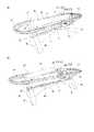
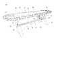
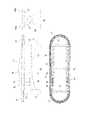
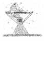
図1は、上に患者が配置されている例示的な手術台10の斜視図を示す。図2A~図2Cは、例示的な手術台10の異なる斜視図を示す。図3A~図3Cは、複数のプラットフォーム区画を備えた例示的な手術台10の異なる図であり、図3Aは正面図であり、図3Bは側面図であり、図3Cは上から見た図である。図4は、例示的な手術台10を構成する部品の分解図である。図5A~図5Cは、さらなる寸法情報を含む例示的な手術台の異なる図であり、図5Aは正面図であり、図5Bは上から見た図であり、図5Cは側面図である。図6は、V字形撮像ユニット48を備えた例示的な手術台10を示す。 FIG. 1 shows a perspective view of an exemplary operating table 10 on which a patient is placed. 2A-2C show different perspective views of an exemplary operating table 10. 3A-3C are different views of an exemplary operating table 10 with a plurality of platform compartments, FIG. 3A is a front view, FIG. 3B is a side view, and FIG. 3C is a top view. Is. FIG. 4 is an exploded view of the parts constituting the exemplary operating table 10. 5A-5C are different views of the exemplary operating table with additional dimensional information, FIG. 5A is a front view, FIG. 5B is a top view, and FIG. 5C is a side view. FIG. 6 shows an exemplary operating table 10 equipped with a V-shaped
手術台10は、手術台の長さ方向に延在する長手方向軸と、長手方向軸に対して直行する横方向軸とを有する長尺形状を有する。手術台10は、手術室の床の上に配置することができる基部12を備える。基部12は、手術台10の長手方向に延在する長尺状のブリッジ部分14を備える。ブリッジ部分には、患者支持プラットフォーム30に面するその上面に、摺動レール又はトラック16が設けられている。摺動レール又はトラック16は、ブリッジ部分14の長手方向及び手術台10の長手方向それぞれに延在している。基部12は、ブリッジ部分14の両側にそれぞれ位置決めされた2つの端部支柱18及び20をさらに備える。2つの端部支柱18及び20は、特に、実質的に台形の形状を有し、各支柱の相対的に幅の広い下端部が床の上に配置され、相対的に幅の狭い上端部がそれぞれのプラットフォーム支持体22、24に接続されている。ブリッジ部分14及び/又は端部支柱18、20は、少なくとも1つのアクチュエータ及び/又は他の可動部品を収容することができる。さらに、ブリッジ部分14及び/又は端部支柱18、20内に床下照明を設けることができる。ブリッジ部分の長さは、たとえば、1950.0mm~2250.0mmの範囲、たとえば2000mmであり得る。(基部の高さに等しい)ブリッジ部分の高さは、250.0mm~550.0mmの範囲、たとえば450.0mmであり得る。長手方向における2つの端部支柱18及び20の各々の下端部の幅は、80.0mm~160.00mmの範囲、たとえば150.0mmであり得る。長手方向に対して直行する横方向における2つの端部支柱18及び20の各々の下端部の幅は、600.0mm~800.0mmの範囲、たとえば700.0mmであり得る。横方向における2つの端部支柱18及び20の各々の上端部の幅は、250.0mm~350.0mmの範囲、たとえば275.0mmであり得る。 The operating table 10 has a long shape having a longitudinal axis extending in the length direction of the operating table and a lateral axis orthogonal to the longitudinal axis. The operating table 10 comprises a base 12 that can be placed on the floor of the operating room. The
2つのプラットフォーム支持体22及び24は、端部支柱18及び20にそれぞれ接続されている。この接続は、好適な接続機構を介することができる。接続機構は、たとえば、端部支柱18及び20の各々にそれぞれ設けられた接続要素21及び23と、プラットフォーム支持体の一部であり得る嵌合接続要素25、45とを含むことができる。各プラットフォーム支持体22、24は、患者支持プラットフォーム30に且つ患者支持プラットフォーム30を包囲するサイドレール36に接続されている支持バー(クロスバー)26、27をそれぞれ有する。各プラットフォーム支持体22、24は、2つの支持アームを有するV字形又はU字形支持支柱28、29をさらに備え、その上端部は、支持バー26、27の端部にそれぞれ接続されている。V字形又はU字形支持支柱の下端部は、たとえば好適な接続機構を介して、基部12の端部支柱18、20にそれぞれ接続されている。 The two platform supports 22 and 24 are connected to the end struts 18 and 20, respectively. This connection can be made via a suitable connection mechanism. The connection mechanism can include, for example,
V字形又はU字形支持支柱の下端部は、250.0mm~350.0mmの範囲内、たとえば275.0mmの横方向の幅を有することができる。V字形又はU字形支持支柱の開き角度は、35°~70°の範囲内であり得る。支持支柱の高さは、600.0mm~750.0mmの範囲内、たとえば625.0mmであり得る。 The lower end of the V-shaped or U-shaped support column can have a lateral width in the range of 250.0 mm to 350.0 mm, for example 275.0 mm. The opening angle of the V-shaped or U-shaped support column can be in the range of 35 ° to 70 °. The height of the support column can be in the range of 600.0 mm to 750.0 mm, for example 625.0 mm.
手術台10の全体的な高さは、たとえば、最大1400.0mm、たとえば895.2mmであり得る。好ましくは、接続機構は、患者支持プラットフォーム30の高さの変更を可能にする、すなわち、患者支持プラットフォーム30を上昇及び下降させるように構成され、したがって、手術台の人間工学を向上させる。言い換えれば、接続機構は、高さ調整機構を含むことができる。一例では、患者支持プラットフォームの高さは、800.0mm~1300.0mmの範囲内で連続的に又は段階的に変更することができる。さまざまな高さ調整機構が可能である。たとえば、高さ調整機構は、入れ子式に伸縮可能な支持柱を含むことができる。 The overall height of the operating table 10 can be, for example, up to 1400.0 mm, for example 895.2 mm. Preferably, the connection mechanism is configured to allow changes in the height of the
手術台10は、患者支持プラットフォーム30の垂直移動をもたらす少なくとも1つのアクチュエータ(たとえば、リニアアクチュエータ)をさらに備えることができる。たとえば、アクチュエータは、支持柱が垂直方向に伸長するか又は畳まれるようにすることができる。たとえば、基部12内に、たとえば端部支柱18及び20内に、少なくとも1つのプラットフォーム支持体22、24内に、又は支柱18、20に接続された伸長可能な支持柱内に、一対のアクチュエータを収容することができる。この配置構成は、上記で説明したように、無菌性に関して相当な利点を提供する。さらに、それは空間を節約し、それにより、小型且つ操作が容易な手術台を提供する。 The operating table 10 may further comprise at least one actuator (eg, a linear actuator) that provides translation of the
さらに、手術台10の上述した三角形の片持ち梁設計により、低重心が維持され、同時に、患者1へのアクセスが容易になる。したがって、全体的な手術時間及び関連するリスクを低減させることができる。さらに、無菌性侵害のリスクを低減させることができる。 Further, the above-mentioned triangular cantilever design of the operating table 10 maintains a low center of gravity and at the same time facilitates access to
手術台10は、手術台10の長手方向において長尺形状、たとえば楕円形又は矩形の形状を有する、患者支持プラットフォーム30を備える。患者支持プラットフォーム30の上面に患者1を位置決めすることができる。ベルト、ストラップ又は他の任意の好適な装置によって、患者支持プラットフォーム30に患者1を確実に固定することができる。患者支持プラットフォームの長さは、たとえば約2130.0mmであり得る。患者支持プラットフォームの幅は、約550.0mmであり得る。 The operating table 10 comprises a
患者支持プラットフォーム30は、たとえば図1~図4に示すように、互いに対して移動可能である複数の区画を備える多区画患者支持プラットフォームであり得る。図1~図4に示す例では、患者支持プラットフォーム30は、互いに対して移動可能である2つの区画32及び34を備え、それにより、たとえば図2Bに示すように、患者支持プラットフォーム30を曲げることができる。第1患者支持プラットフォーム区画32及び第2患者プラットフォーム区画34は、たとえば、互いに対して片持ちにすることができ、又は言い換えれば、好適なヒンジ継手により互いに接続することができる。さらに、2つの部分をプラットフォーム支持体22及び24に接続することができ、この接続は、プラットフォーム区画32及び34のプラットフォーム支持体に対するそれぞれの枢動運動を可能にする好適なヒンジ継手を介することができる。 The
手術台10の多区画配置構成により、手術中の患者1の正確な位置決め及び再位置決めが容易になる。当然ながら、患者支持プラットフォームは、互いに対して移動可能な3つ以上の区画を備えることができる。たとえば図5A~図5Cに示すように、患者支持プラットフォーム30は1つの区画のみを有することも可能である。 The multi-section layout of the operating table 10 facilitates accurate positioning and repositioning of
患者支持プラットフォーム30は、サイドレール(外部レール)36によって包囲されている。図に示す例では、サイドレール36は、長尺状楕円形の形状を有する。サイドレール36は、撮像装置100の撮像ユニット48、50も包囲する。言い換えれば、撮像ユニット48、50は、サイドレール36の外周部の範囲内にあり得る。したがって、サイドレール36は、外科医及び助手の撮像装置100との干渉のリスクを低減させる。 The
サイドレール36の長さは、2700.0mm~3500.0mmbの範囲内、たとえば3249.8mmであり得る。サイドレール36の幅は、650.0mm~1100.0mmの範囲内、たとえば、974.0mmであり得る。手術担当者の損傷を防止するために、サイドレール36の少なくとも一部に当て物をすることができ、又はサイドレール36の少なくとも一部を軟質材料から作製することができる。 The length of the
サイドレール36は、患者支持プラットフォーム30の2つの長辺側に2つの周囲レール部分又は周囲ビーム38及び40を、患者支持プラットフォーム30の短辺側に2つの端部レール部分42及び44をそれぞれ備える。周囲レール部分38及び40は、実質的に直線状又はわずかに曲線状の部分であり得る。撮像ユニット48及び50は、周囲レール部分38及び40の間に配置することができる。 The
周囲レール部分38及び40と患者支持プラットフォーム30のそれぞれの長辺部との間の距離は、均一とすることができ、たとえば、125.0mm~250.0mmの範囲、たとえば160.0mmであり得る。端部レール部分42、44は、曲線状とすることができ、たとえば、半円形又は半楕円形の形状を有することができる。周囲レール部分端部レール部分42及び44と患者支持プラットフォーム30のそれぞれの短辺側との間の最大距離は、たとえば、250.0mm~600.0mmの範囲、たとえば450.0mmであり得る。 The distance between the
プラットフォーム支持体22及び24の支持バー26の両端部は、サイドレール36に接続されている。こうした構造により、手術台10の全体的な無菌性の向上が達成され、及び/又は、患者支持プラットフォーム30上での撮像システム100に対する患者1の信頼性の高い相対的な位置決めを達成することができ、したがって、(具体的には、超音波検査、コンピュータ断層撮影(CT)、磁気共鳴断層撮影(MRT)のような断面撮像)及び2D又は3D X線透視法の場合に、より正確な撮像をもたらす。周囲レール部分38、40及び/又は端部レール部分42、44は、円形又は楕円形の断面を有する実質的に管状であり得る。当然ながら、他の断面形状が可能である。サイドレール36の高さは、40.0mm~150.0mmの範囲内、たとえば75.0mmであり得る。 Both ends of the support bars 26 of the platform supports 22 and 24 are connected to the side rails 36. Such a structure can achieve improved overall sterility of the operating table 10 and / or achieve reliable relative positioning of
サイドレール36に、取付トラック(器具配置部分)をさらに設けることができ、その上又は中に、外科用機器及び付属品を取り付けるか又は配置し、好ましくはその上/その中に確実に保持又は固定することができる。たとえば、周囲レール部分38及び40は、導管、及び(術野に近接して固定する表示画面等)付属品及び機器用の取付トラック(器具配置部分)として作用する、押出形材であり得る。一例では、取付トラックは、サイドレール36の一部に(たとえば、周囲レール部分38、40及び/又は端部レール部分42、44のうちの1つ又は複数の一部に)設けることができる。器具配置部分の寸法は、手術台の目標とする用途に応じて変更することができる。 A mounting track (instrument placement portion) may be further provided on the side rails 36 to mount or place surgical equipment and accessories on or in it, preferably securely held or placed on / in it. Can be fixed. For example, the
さらに、取付トラックを通して、ケーブル(たとえば、神経モニタリングケーブル)がアクセス可能であり得る。ケーブルは、取付トラックとともに完全体であり得る。 In addition, cables (eg, neural monitoring cables) may be accessible through the mounting track. The cable can be complete with the mounting track.
図8に、例示的な器具配置部分を示す。器具配置部分は、たとえば、サイドレール36の一部をその円周方向に覆うカバー72によって形成され得るか、又はカバー72を含むことができる。カバー72は、外部装置(たとえば、外科用器具等)のそれぞれのボルト又は他の接続要素を受け入れるように構成されている複数のアパーチャを備える。当然ながら、カバー72は、たとえばレール、ボタン、締結具等、他のタイプの接続要素又は区画を備えることができる。 FIG. 8 shows an exemplary instrument placement portion. The instrument placement portion may, for example, be formed by a
取付トラックを設けることにより、手術台の人間工学を向上させることができ、その結果、全体的な手術時間が短縮される。 The mounting track can improve the ergonomics of the operating table, resulting in shorter overall operating time.
サイドレール36に、たとえば、モニタ、タッチスクリーン等の追加の外部装置のそれぞれの取付部分に接続可能な、1つ又は複数の取付部分を設けることができる。取付部分が設けられた例示的なサイドレール36を図9に示す。図10は、外部装置が取り付けられている摺動レールの斜視図を示す。たとえば、半円形又は半楕円形の端部レール部分42及び44の一方又は両方に、少なくとも1つの取付部分62を設けることができる。レール部分36の取付部分62は、たとえば、外部装置支持体68(たとえば、モニタスタンド)の取付アーム68が取り付け可能である取付脚部を含むことができる。他の任意のタイプのコネクタを採用することができる。図10に示すように、2つのモニタ又はディスプレイ64及び66を、取付スタンド68に取り付けるか又は取付スタンド68によって支持することができる。一例では、取付スタンド68の取付位置は適応性があり、又は言い換えれば可変であり得る。たとえば、取付スタンド68とサイドレール36との接続は、サイドレール36に沿って取付スタンドを新たな位置まで移動させることができるようなものであり得る。ディスプレイ64又は66は、撮像ユニット48、50のうちの1つ又は複数による1つの画像又は複数の獲得された画像、及び/又は、手術ナビゲーション情報、患者のバイタルパラメータに関する情報(心拍数、血圧、酸素飽和度等)等のさらなる情報を表示することができる。この配置構成により、外科医は、術野を実質的に覆い隠すことなく、必要な情報を迅速に把握することがより容易になる。 The side rails 36 may be provided with one or more mounting portions that can be connected to the respective mounting portions of additional external devices such as monitors, touch screens and the like. An
さらに、図8に示す例では、サイドレール36又はその一部(たとえば、周囲部分38、40のうちの一方及び/又は端部レール部分42、44のうちの一方)は、中空の、実質的に円筒状の形状を有することができる。中空サイドレール36又はその一部内に、電気ケーブル70、(たとえば、液圧式高さ調整機構のための空気又は他の流体の通路用の)少なくとも1つの流体導管若しくはチューブ、(たとえば、高さ調整制御機構及び/又は撮像装置100を移動させる制御機構の)電気部品、及び/又は他の構成要素等のさまざまな構成要素を設けることができる。言い換えれば、サイドレール36又はその一部は、上述した構成要素のうちの任意のものを収容することができる。これには、無菌性に関して相当な利点(手術台を滅菌し及び/又は無菌状態を維持する容易さ)がある。さらに、手術台の保守を改善することができるとともに、術野を遮るリスクを低減させることができる。 Further, in the example shown in FIG. 8, the
手術台10は、手術台10と一体的に形成された撮像装置100を備える。撮像装置100は、任意の好適な撮像装置、たとえば、X線撮影装置、磁気共鳴画像化装置、ポジトロン放出断層撮影装置、超音波撮像装置、コンピュータ断層撮影装置等、及びそれらの任意の組合せであり得る。撮像装置100は、少なくとも1つの放射線源(たとえば、X線源)と少なくとも1つの放射線検出器(たとえば、X線検出器)とを備えるか又はそれらによって構成される。図に示す例では、放射線源は、1次元又は2次元アレイ52に配置された複数の放射線源素子を備える。放射線検出器は、1次元又は2次元アレイ54で配置された複数の検出器素子を備える。 The operating table 10 includes an
撮像装置100は、基部12及び患者支持プラットフォーム30に対して移動可能である、基部12の上の撮像装置支持体47によって支持される。 The
撮像装置100は、1つ又は複数の(特に、2つ又は3つの)撮像ユニット48、50を備える。各撮像ユニットは、特に底部に配置された接続部分において接続され及び/又は基部12によって支持される基部12の上に又は基部12に取り付けられた、一対のアーム48A及び48B又は50A及び50Bをそれぞれ備える。したがって、撮像ユニット48、50を備える撮像装置100は、基部12から「懸架され」ている。各撮像ユニット48、50は、端部が開放したC字状又はV字状の形状(特に、実質的に半円形又は半楕円形の形状)を有する全体的な幾何学的形状を実質的に有する。特に、各撮像ユニット48、50は、約180°~約270°の範囲、さらに詳細には約200°~約250°の範囲の方位角の広がり、さらに詳細には約220°の方位角の広がりを有する。 The
各撮像ユニット48、50の2つのアーム48A、48B又は50A、50Bは、患者支持プラットフォーム30の2つの長辺側に又はその近くに配置されている。したがって、患者支持プラットフォーム30は、少なくとも一部には、各撮像ユニット48、50のアーム50A、50Bの間に位置決めされている。さらに、撮像ユニット48、50は、サイドレール36の外周部、たとえば、周囲サイドレール部分38及び40の間に位置決めされている。2つの撮像ユニット40、50は、互いに隣接して位置決めすることができる。2つの撮像ユニット48、50の間の相対距離は、一定であっても変更可能であってもよい。複数の撮像ユニット40、50を、摺動レール又はトラック16に沿って併せて又は独立して変位させることができる。 The two
各撮像ユニット48、50のアームのうちの一方は、少なくとも1つの放射線源を担持し、撮像ユニットの他方のアームは、少なくとも1つの放射線検出器を担持する。より具体的には、1つ又は複数の放射線源素子は、アーム48A、58Bのうちの一方の内面(すなわち、患者支持プラットフォーム30に実質的に面する面)の上又は中又は内面に、特に、実質的にアームの長さに沿って延在する1次元又は2次元アレイ52、54の形態で、配置されている。放射線検出器素子は、それぞれの撮像ユニット48、58のアーム48BA、50Aのうちの他方の内面に、実質的に特に、アームの長さに沿って延在する1次元又は2次元アレイの形態で配置されている。 One of the arms of each of the
たとえば、撮像ユニット48、50の2つのアーム48A及び48B又は50A及び50Bが、連続的な半円形(C字状)の形状を実質的に形成する場合、半円形の形状の一方の半体は、放射線源素子のアレイ52を担持することができ、他方の半体は、放射線検出器のアレイ54を担持することができる。放射線検出器素子又は放射線源素子が、それぞれのアーム50A、50Bの全長に沿って延在することは必須ではなく、それらは単に、それぞれのアーム50A、50Bの1つ又は複数の部分に設けることができる。 For example, if the two
図に示す例では、2組の放射線源素子及び放射線検出器素子があり、各組が撮像ユニット48及び50の異なるものにそれぞれ設けられている。図に示す例では、図4に示すように、第1撮像ユニット48に設けられた、組のうちの一方の放射線源素子のアレイは、第2撮像ユニット50に設けられた第2組の検出器素子のアレイに隣接又は近接して配置されている。他の配置も可能である。 In the example shown in the figure, there are two sets of radiation source elements and radiation detector elements, and each set is provided in
各撮像ユニット48、50は、基部12及び患者支持プラットフォーム30に対して、より具体的には手術台10の長手方向軸に対して(たとえば、約360度以下にわたって)回転可能であり、したがって、複数の方向から及び/又は複数の断面図において患者1の画像を撮影することができる。 Each
各撮像ユニット48、50は、1つ又は複数の位置に選択的に位置決めすることができる。具体的には、各撮像ユニット48、50は、具体的には画像獲得を実施する必要がないとき、後退又は待機位置に位置決めすることができる。後退又は待機位置では、患者支持プラットフォーム30の上面よりも上方に延在する各撮像ユニット48、50のアーム48A、48B、50A、50Bの上端部の高さは、(たとえば、手術台10の上に患者1を配置したとき)外科チーム及び/又は助手を実質的に妨げないように、たとえば、約300mm(患者支持プラットフォーム幅が最小に設定される)~約525.5mmの範囲内、たとえば、約450.0mm未満であり得る。 Each
好ましくは、後退又は待機位置にあるとき、各撮像ユニットのアーム50A、50Bの上端部は、患者支持プラットフォームの上面よりも高く延在しない(たとえば、図2Cを参照)。 Preferably, when in the retracted or standby position, the upper ends of the
撮像ユニットのジオメトリ及び/又は配置構成(たとえば、後退又は待機位置におけるアームの上端部の高さ等)は、撮像装置の人間工学的要件及び幾何学的要件/制約(たとえば、放射線医学幾何学設計要件等)、期待される画像品質閾値等、さまざまな制約及び/又は要件に基づいて決定することができる。 The geometry and / or placement configuration of the imaging unit (eg, height of the top of the arm in the retracted or standby position, etc.) is the ergonomic and geometric requirements / constraints of the imaging device (eg, radiological geometric design). It can be determined based on various constraints and / or requirements such as requirements), expected image quality thresholds, etc.
各撮像48、50は、患者の身体の関連部分の画像を獲得することができる、1つ又は複数の検出位置にさらに位置決めすることができる。図7に示すように、検出位置では、放射線源52から放出される放射線の少なくとも一部が、患者の身体を通って伝播し、放射線検出器54によって検出され得る。言い換えれば、検出位置では、撮像すべき患者の身体の少なくとも一部が、放射線源52と放射線検出器54との間に配置される。上記で説明したように、撮像すべき身体部分の画像が撮影される種々の方向に対応する複数の検出位置があり得る。 Each
撮像ユニット48、50を、たとえば後退又は待機位置に対して、長手方向軸を中心とする異なる方位角位置で位置決めされるように、基部12及び/又は患者支持プラットフォーム30に対して長手方向軸を中心に回転又は枢動又は旋回させることにより、検出された位置まで移動させることができる。 The longitudinal axis with respect to the
たとえば、撮像ユニット48、50が患者支持プラットフォーム30の上方の位置まで回転すると、(たとえば、図5Cに示すような、患者の周囲のCアームの完全に閉じた位置における)撮像ユニットの頂点又は頂部と患者支持プラットフォーム30との間の最大距離は、たとえば、約350.0mm(患者支持プラットフォームの幅が最小に設定される)~約750.0mmの範囲、たとえば、約502.5mmであり得る。円形C字形の場合、距離は、約600.0mm及び(台30の幅550.0mmにより)1050.0mmであり得る。 For example, when the
(手術台10の長手方向に対して直交する横方向において測定された)撮像ユニット48又は50の2つのアーム48A及び48B又は50A及び50Bそれぞれの間の最大距離は、約500mm~約1500mmの範囲、さらに詳細には約600mm~1050mmの範囲、さらに詳細にはたとえば約750mmであり得る。アーム50A、50Bが実質的に連続的な半円形の形状を形成する場合、半円形の形状の半径は、たとえば、約400.0mm~約750mmの範囲、より詳細には約400.0mm~約502.5mmの範囲、たとえば約450mmであり得る。(長手方向に測定された)各アーム50A及び50Bの幅は、約60.0mm~約400.0mm、より具体的には約150mm~約250mmの範囲、たとえば183.5mmであり得る。 The maximum distance between each of the two
撮像ユニットの各々のジオメトリ及び/又は配置構成は、撮像装置の人間工学的要件及び幾何学的要件/制約(たとえば、放射線医学幾何学設計要件等)、期待される画像品質閾値等のさまざまな制約及び/又は要件に基づいて設定することができる。 Each geometry and / or placement configuration of the imaging unit has various constraints such as ergonomic requirements and geometric requirements / constraints (eg, radiological geometric design requirements, etc.) of the imaging device, expected image quality thresholds, etc. And / or can be set based on requirements.
2つの撮像ユニット48、50は、独立して移動可能とすることができ、たとえば、手術台10の長手方向軸を中心に独立して移動可能とすることができ、及び/又は、摺動レール又はトラック16に沿って独立して変位可能とすることができる。 The two
図5A~図5Cに示す例では、撮像ユニットのうちの一方、すなわち撮像ユニット48は、他方の撮像ユニット50に対して、且つ手術台10の長手方向軸に対して(したがって、患者支持プラットフォーム30及び基部12の長手方向軸に対してもまた)回転する。撮像ユニット48、50はまた、基部12に対して及び/又は互いに対して枢動可能であり得る。たとえば、撮像ユニット48、50は、手術台10の長手方向軸に対して(したがって、基部12及び患者支持プラットフォーム30の長手方向軸に対してもまた)直交する軸に対して枢動可能であり得る。これによりさらに、患者へのアクセスが容易になり、患者の画像を種々の方向から撮影することができる。 In the example shown in FIGS. 5A-5C, one of the imaging units, i.e., the
特定の実施形態によれば、撮像48、50は、(撮像装置支持体の一例としての)支持フレーム47に取り付けられる。支持フレーム47の代わりに、他の任意の好適な結合機構を採用することができる。支持フレーム47は、特に摺動レール又はトラック16を介して基部12の上に又は基部12に摺動可能に取り付けられ、したがって、患者1へのアクセスを容易にし、及び/又は患者1の種々の部分の画像が撮影されるのを可能にする。特に、上記で説明したように、患者の身体の関連部分の少なくとも1つの画像を(たとえば回転スキャンを実施することにより)取得することができる第1位置(検出位置)、及び(たとえば、患者支持プラットフォーム30の端部における又はその近くの)待機又は後退位置、又は術野に干渉しない他の任意の位置まで、撮像ユニット48、50を備える撮像装置100を長手方向に移動させることができる。支持フレーム47とそれに取り付けられた撮像装置100を移動させる前に、支持フレーム47及び/又は撮像装置100の1つ又は複数の最後の検出位置を記憶することができる。必要な場合は、記憶された位置まで又は記憶された位置のうちの1つまで、支持フレーム47及び撮像装置100を自動的に移動させることができる。これにより、撮像装置100の再位置決め及び/又は較正に必要な時間が大幅に短縮され、画像獲得の精度が上昇する。基部12及び/又は患者支持プラットフォーム30に対する支持フレーム47及び/又は撮像装置100の位置は、好適な追跡システム、たとえば光学又は電子追跡システムによって追跡することができる。追跡システム又はその少なくとも一部は、サイドレール36内に組み込むことができる。たとえば図8に示すように、支持フレーム47及び/又は撮像装置100の移動を制御するために、サイドレール36に(たとえば、ボタン、タッチスクリーン等の形態の)少なくとも1つの制御インタフェースを設けることができる。 According to a particular embodiment, the
支持フレーム47は、手術台10の長手方向軸に対する撮像ユニット48、50の回転を可能にしながら、撮像ユニット48、50を担持し、それにより、回転スキャンを実施することができる。 The
図に示す例では、基部12は、(特に、患者支持プラットフォーム30の長手方向軸に対応する)基部12の長手方向軸に沿って実質的に延在する摺動レール又はトラック16を備える。撮像装置100、より具体的には撮像ユニット48、50は、支持フレーム47又は他の任意の好適な結合機構を介して、摺動レール又はトラック16に摺動可能に取り付けられている。さらに、各撮像ユニット48、50に対して異なる支持フレームを設けることができ、それにより、各撮像ユニット48、50の独立した摺動運動が可能になる。 In the example shown in the figure, the
手術台10は、基部12に対して撮像装置支持体46を移動させ、及び/又は撮像装置100の撮像ユニット48、50を回転可能に及び/又は枢動可能に移動させる、少なくとも1つのアクチュエータ(たとえば、リニアアクチュエータ)をさらに備えることができる。少なくとも1つのアクチュエータは、基部12内に(たとえば、ブリッジ部分14内に)収容することができる。 The operating table 10 moves the image pickup device support 46 relative to the
上述したように、手術台10は、基部12に対する撮像装置支持体47及び/又は(特に、放射線源及び放射線検出器から構成された)撮像装置100の位置を追跡する、追跡システム(たとえば、光学、電子等の追跡システム)をさらに備えることができる。これにより、画像獲得の較正が容易になる。別法として又はさらに、基部12に対する及び/又は撮像装置100に対する、患者1又は撮像される患者の身体の部分の位置を追跡する追跡システムを設けることができる。 As mentioned above, the operating table 10 is a tracking system (eg, optical) that tracks the position of the
上述した手術台10を用いて患者の身体部分の画像を取得する方法は、患者支持プラットフォーム30の上面に患者1を位置決めすることと、患者支持プラットフォーム30に対して撮像装置支持体47を画像獲得位置まで移動させることとを含むことができる。撮像装置支持体47の移動は、たとえば、患者支持プラットフォーム30に対する1つ又は複数の撮像ユニット48、50の摺動運動及び/又は回転運動を含むことができる。画像獲得位置では、患者1は、撮像ユニット48のアーム48A及び48B並びに/又は撮像ユニット50のアーム50A及び50Bそれぞれの間に、少なくとも部分的に配置又は位置決めされ、それにより、(たとえば、放射線源素子の1次元又は2次元アレイによって構成された)少なくとも1つの放射線源52と、(たとえば、放射線検出器素子の1次元又は2次元アレイによって構成された)少なくとも1つの放射線検出器54とによって構成された又はそれらを備える撮像装置100により、患者の身体部分の少なくとも1つの画像(具体的には、断面画像)を取得することができる。上述したように、手術台10の長手方向軸に対して撮像ユニット48、50を回転させることにより、種々の方向又は向きからの複数の画像を取得することができる。放射線検出器54によって検出された信号は、コンピュータ又はコンピューティングシステムに送信することができ、そこで、その信号を処理して、患者の身体部分の2次元又は3次元画像を形成することができる。画像は、ディスプレイ、たとえば、サイドレール36、38及び/又は40に取り付けられているディスプレイに、表示することができる。放射線検出器54からの信号は、手術中に外科医を支援するために使用され得るナビゲーションシステムにも送信することができる。得られた画像、及び任意選択的にさらなる情報(ナビゲーション情報、バイタルパラメータ情報等)は、1つ又は複数のディスプレイ、たとえば、図10に示す外部ディスプレイ64及び66に表示することができる。 The method of acquiring an image of a patient's body portion using the operating table 10 described above is to position the
上述したことによる手術台及び方法は、さまざまなタイプの外科手術において、特に脊髄外科、神経外科、脳外科、整形外科、低侵襲処置、インプラント装置留置、外傷学、耳鼻咽喉科手術、副鼻腔手術、顎顔面外科、形成外科、歯科学、生研等、複雑な外科処置を実施するために採用することができる。 The operating tables and methods according to the above are used in various types of surgery, especially spinal surgery, neurosurgery, brain surgery, orthopedics, minimally invasive procedures, implant device placement, traumatology, otolaryngology surgery, sinus surgery, It can be used to perform complex surgical procedures such as maxillofacial surgery, plastic surgery, dentistry, and biopsy.
上述したことによる手術台及び方法は、以下の利点のうちの1つ又は複数を有することができる。 The operating table and method according to the above can have one or more of the following advantages.
撮像装置100は、撮像装置支持体46を介して基部12に取り付けられ、又は言い換えれば接続されるため、手術台10自体の一体化部分を形成する。したがって、手術台10に対する撮像装置支持体46及び撮像装置100の相対位置は、正確な方法で取得及び/又は維持することができる。さらに、撮像装置100を、手術台10に対する、より具体的には基部12及び/又は患者支持プラットフォーム30に対する所望の位置まで正確に移動させることができる。したがって、画像獲得の精度を大幅に向上させることができる。さらに、撮像装置100の較正のプロセスを大幅に改善することができ、及び/又は較正手順に必要な時間を大幅に短縮することができる。したがって、患者被爆時間及び放射線量を低減させることができ、外科的介入の安全性を向上させることができる。さらに、患者1へのアクセスも容易になるため、全体的な手術時間及び関連するリスクを低減させることができる。さらに、記載した手術台10は、特に、米国特許第7188998B2号明細書又は米国特許出願公開第2012/0330134A1号明細書によるシステム等のシステムと比較して、無菌性の確保及び維持に関して相当な利点を提供する。さらに、撮像装置100は、手術台10の一体化部分であるとともに、手術台10から直接懸架されているため、スペースの節約に関して相当な利点を有する。たとえば、外部撮像装置のさらなる、一般に幾分かかさばる基部に対して、スペースを提供する必要がない。 Since the
上述した例示的な手術台10は、術野への開放した容易なアクセスとともに、優れた機械的安定性をさらに提供することができる。さらに、ロボット機能(たとえば、コントローラ、アクチュエータ)を容易に組み込むことができる。いくつかの例では、手術台10、たとえば、基部12、プラットフォーム支持体22、24、並びに/又はサイドレール36、38及び/若しくは40は、少なくとも部分的に、1つ又は複数の制御要素、1つ又は複数のアクチュエータ、少なくとも1つの電気ケーブル、少なくとも1つの(特に流体)管、センサ及び/又は他の要素を収容することができ、又は言い換えれば、内部にそれらが配置されるようにすることができる。これらの要素は、外科手術中に露出しないため、無菌性要件を容易に満たすとともに維持することができる。さらに、手術台12内にナビゲーション及び/又は他のユーザインタフェース要素(たとえば、制御インタフェース要素76)を組み込むことができ、それにより、手術台10の使いやすさ及び/又は人間工学が向上する。 The exemplary operating table 10 described above can further provide excellent mechanical stability, as well as open and easy access to the surgical field. In addition, robotic functions (eg, controllers, actuators) can be easily incorporated. In some examples, the operating table 10, eg,
提案した手術台の例は、モジュール式であり及び/又は拡張可能であり、又は、ディスプレイ、タッチスクリーン、制御パネル等、他の外部装置と統合可能であり得る。さらに、提案した手術台の例に、外科用付属品、器具等、さらなる外科装置を受け入れ及び/又は保持するように構成され得る区画を設けることができる。 The proposed operating table example may be modular and / or expandable, or integrate with other external devices such as displays, touch screens, control panels, etc. In addition, the proposed operating table example may be provided with compartments that may be configured to receive and / or hold additional surgical equipment, such as surgical accessories, instruments, and the like.
上述した例示的な手術台10は、容易に保守することができる、単純な、頑強な且つ汎用性のある構造を示すことができる。さらに、操作のために専門技術者と契約することが不要である可能性があり、それによりコストが削減される。したがって、提案する手術台10は、直接的及び間接的なコスト削減を提供する。 The exemplary operating table 10 described above can exhibit a simple, robust and versatile structure that can be easily maintained. In addition, it may not be necessary to contract with a professional technician for operation, thereby reducing costs. Therefore, the proposed operating table 10 provides direct and indirect cost savings.
複数の例について上述した。言うまでもなく、本発明は、これらの例に限定されず、そのさまざまな変更形態及び/又は組合せを包含することができる。 A plurality of examples have been described above. Needless to say, the present invention is not limited to these examples, and can include various modifications and / or combinations thereof.
1 患者
10 手術台
12 基部
14 ブリッジ部分
16 摺動レール又はトラック
18、20 端部支柱
21、23 接続要素
22、24 プラットフォーム支持体
25 接続要素
26、27 支持バー
28、29 支持支柱
30 患者支持プラットフォーム
32 第1患者支持プラットフォーム区画
34 第2患者支持プラットフォーム区画
36 サイドレール
38、40 周囲レール部分
42、44 端部レール部分
45 コネクタ要素(結合機構レール、支持支柱、端部支柱)
46 撮像装置支持体
47 支持フレーム
48 第1撮像ユニット
48A、48B 第1撮像ユニットのアーム
50 第2撮像ユニット
50A、50B 第2撮像ユニットのアーム
52 放射線源素子アレイ(放射線源の例)
54 放射線検出器素子アレイ(放射線検出器の例)
60 サイドレールの取付部分(たとえば、取付脚部)
62 外部装置の取付部分(たとえば、取付アーム)
64、66 外部装置(たとえば、ディスプレイ、タッチスクリーン)
68 外部装置支持体(たとえば、モニタスタンド)
70 電気ケーブル
72 流体導管又は管
74 カバー
76 制御インタフェース(たとえば、高さ調整制御インタフェース)
100 撮像装置1
46
54 Radiation detector element array (example of radiation detector)
60 Side rail mounting part (for example, mounting leg)
62 Mounting part of external device (for example, mounting arm)
64, 66 External devices (eg displays, touch screens)
68 External device support (eg monitor stand)
70
100 Imaging device
Claims (15)
Translated fromJapanese患者支持プラットフォーム(30)と、
前記基部(12)に接続され、及び前記基部(12)上に前記患者支持プラットフォーム(30)を支持するように構成された、少なくとも1つのプラットフォーム支持体(22、24)と、
前記基部(12)に取り付けられている撮像装置支持体(47)と、
前記撮像装置支持体(47)に取り付けられた撮像装置(100)であって、
第1アーム(48A、50A)と第2アーム(48B、50B)とを備える少なくとも1つの撮像ユニット(48、50)であって、前記患者支持プラットフォーム(30)が、前記第1アーム(48A、50A)と前記第2アーム(48B、50B)との間に少なくとも部分的に位置決めされている、少なくとも1つの撮像ユニット(48、50)と、
前記第1アーム(48A、50A)の中又は上に位置決めされた第1放射線源(52)及び前記第2アーム(48B、50B)の中又は上に位置決めされた第1放射線検出器(54)であって、前記第1放射線検出器(54)が、前記第1放射線源(52)によって放出される放射線の少なくとも一部を検出するように配置されている、第1放射線源(52)及び第1放射線検出器(54)と、
を含む撮像装置(100)と、
を備える、手術台(10)。Base (12) and
Patient support platform (30) and
With at least one platform support (22, 24) connected to the base (12) and configured to support the patient support platform (30) on the base (12).
An image pickup device support (47) attached to the base (12) and
An image pickup device (100) attached to the image pickup device support (47).
At least one imaging unit (48, 50) comprising a first arm (48A, 50A) and a second arm (48B, 50B), wherein the patient support platform (30) is the first arm (48A, 50B). With at least one imaging unit (48, 50) positioned at least partially between the second arm (48B, 50B) and the second arm (48B, 50B).
A first radiation source (52) positioned in or above the first arm (48A, 50A) and a first radiation detector (54) positioned in or above the second arm (48B, 50B). The first radiation source (52) and the first radiation source (52), wherein the first radiation detector (54) is arranged to detect at least a part of the radiation emitted by the first radiation source (52). The first radiation detector (54) and
An image pickup device (100) including
The operating table (10).
前記少なくとも1つの撮像ユニット(48、50)の前記第2アーム(48B、50B)が第2放射線源を含み、前記少なくとも1つの撮像ユニット(48、50)の前記第1アーム(48A、50A)が、前記第2放射線源から放出される放射線の少なくとも一部を検出するように配置された第2放射線検出器を含む、請求項1~3のいずれか一項に記載の手術台(10)。The arms (48A, 48B, 50A, 50B) of the at least one imaging unit (48, 50) are arranged so as to have substantially a C-shape or a V-shape, and / or the at least one imaging unit. The second arm (48B, 50B) of (48, 50) includes the second radiation source, and the first arm (48A, 50A) of the at least one imaging unit (48, 50) contains the second radiation source. The operating table (10) according to any one of claims 1 to 3, comprising a second radiation detector arranged to detect at least a portion of the radiation emitted from the source.
前記手術台(10)若しくはその一部が炭素繊維から形成されている、請求項1~6のいずれか一項に記載の手術台(10)。The patient support platform (30) is movable perpendicular to the base (12) and / or
The operating table (10) according to any one of claims 1 to 6, wherein the operating table (10) or a part thereof is formed of carbon fiber.
特に上面に摺動レール又はトラック(16)が設けられているブリッジ部分(14)であって、前記摺動レール又はトラック(16)が実質的に、前記ブリッジ部分(14)の長手方向に延在している、ブリッジ部分(14)と、
前記ブリッジ部分(14)に、特にその両側の先端部に又はその近くに位置決めされた2つの端部支柱(18、20)であって、任意選択的に台形状の形状を有し、下端部が床上に配置可能であり、上端部が前記プラットフォーム支持体(22、24)に接続されている、2つの端部支柱(18、20)と、
を備える、請求項1~7のいずれか一項に記載の手術台(10)。The base (12)
In particular, a bridge portion (14) provided with a sliding rail or track (16) on the upper surface, wherein the sliding rail or track (16) substantially extends in the longitudinal direction of the bridge portion (14). The existing bridge part (14) and
Two end struts (18, 20) positioned at or near the bridge portion (14), particularly at or near the tips on either side thereof, optionally having a trapezoidal shape and a lower end. With two end stanchions (18, 20), which can be placed on the floor and whose upper ends are connected to said platform supports (22, 24).
The operating table (10) according to any one of claims 1 to 7.
前記患者支持プラットフォーム(30)に、任意選択的に前記患者支持プラットフォーム(30)を包囲するサイドレール(36)に接続されている支持バー(26、27)と、
2つの支持アームを有するV字形又はU字形支持支柱(28、29)であって、その上端部が、前記支持バー(26、27)の端部にそれぞれ接続されている、V字形又はU字形支持支柱(28、29)と、
を備える、請求項1~8のいずれか一項に記載の手術台(10)。The platform support
The patient support platform (30) is optionally connected to a support bar (26, 27) connected to a side rail (36) surrounding the patient support platform (30).
A V-shaped or U-shaped support column (28, 29) having two support arms, the upper end of which is connected to the end of the support bar (26, 27), respectively. Support columns (28, 29) and
The operating table (10) according to any one of claims 1 to 8.
前記サイドレール(36)が、電気ケーブル、流体導管及び/又は電気部品のうちの少なくとも1つを収容する中空管状断面形状を有する、請求項12に記載の手術台(10)。One or more mounting portions (60), and / or surgical equipment and accessories, to which the side rails (36) can be connected to the respective mounting portions (62) of the additional external device (64, 66). It comprises a dispositionable instrument disposition portion (72) and / or the side rail (36) has a hollow tubular cross-sectional shape that accommodates at least one of an electrical cable, fluid conduit and / or electrical component. The operating table (10) according to claim 12.
前記基部(12)に対する及び/若しくは前記撮像装置(100)に対する、前記患者若しくは撮像される前記患者の身体の部分の位置を追跡するように構成された追跡システム
をさらに備える、請求項1~13のいずれか一項に記載の手術台(10)。A tracking system configured to track the position of the imaging device support (46) and / or the imaging device (100) with respect to the base (12) and / or the patient support platform (30), and / or. 13. The operating table (10) according to any one of the above items.
前記患者支持プラットフォーム(30)の上面に患者(1)を位置決めすることと、
前記撮像装置(100)を前記患者支持プラットフォーム(30)に対して画像獲得位置まで移動させ、前記撮像装置(100)により患者の身体部分の少なくとも1つの画像を取得することと、
を含む、患者の身体部分の画像を取得する方法。To provide the operating table (10) according to any one of claims 1 to 14,
Positioning the patient (1) on the upper surface of the patient support platform (30) and
The image pickup device (100) is moved to the image acquisition position with respect to the patient support platform (30), and the image pickup device (100) is used to acquire at least one image of the patient's body part.
How to get an image of a patient's body part, including.
Applications Claiming Priority (3)
| Application Number | Priority Date | Filing Date | Title |
|---|---|---|---|
| EP19160439.6AEP3705048B1 (en) | 2019-03-04 | 2019-03-04 | A surgical table with an integrated imaging device |
| EP19160439.6 | 2019-03-04 | ||
| PCT/EP2020/055148WO2020178136A1 (en) | 2019-03-04 | 2020-02-27 | A surgical table with an integrated imaging device |
Publications (2)
| Publication Number | Publication Date |
|---|---|
| JP2022523431Atrue JP2022523431A (en) | 2022-04-22 |
| JP7510948B2 JP7510948B2 (en) | 2024-07-04 |
Family
ID=65685204
Family Applications (1)
| Application Number | Title | Priority Date | Filing Date |
|---|---|---|---|
| JP2021553054AActiveJP7510948B2 (en) | 2019-03-04 | 2020-02-27 | Operating table with integrated imaging device |
Country Status (4)
| Country | Link |
|---|---|
| US (1) | US12357248B2 (en) |
| EP (1) | EP3705048B1 (en) |
| JP (1) | JP7510948B2 (en) |
| WO (1) | WO2020178136A1 (en) |
Families Citing this family (2)
| Publication number | Priority date | Publication date | Assignee | Title |
|---|---|---|---|---|
| EP3705048B1 (en)* | 2019-03-04 | 2021-04-21 | Boscherini, Duccio | A surgical table with an integrated imaging device |
| CN113288425A (en)* | 2021-05-27 | 2021-08-24 | 徐州医科大学附属医院 | Visual navigation system for guide pin in fixation of limb fracture |
Citations (8)
| Publication number | Priority date | Publication date | Assignee | Title |
|---|---|---|---|---|
| US5048069A (en)* | 1990-03-14 | 1991-09-10 | Fischer Imaging Corporation | Dual-slide support mechanism for X-ray system components |
| JPH1066690A (en)* | 1997-07-30 | 1998-03-10 | Analogic Corp | X-ray tomographic photographing device |
| US20050054915A1 (en)* | 2003-08-07 | 2005-03-10 | Predrag Sukovic | Intraoperative imaging system |
| JP2009534159A (en)* | 2006-05-05 | 2009-09-24 | ロジャー・ピー・ジャクソン | Patient positioning support structure |
| JP2010273941A (en)* | 2009-05-29 | 2010-12-09 | Toshiba Corp | Bed equipment |
| US20120256099A1 (en)* | 2011-04-07 | 2012-10-11 | Mobius Imaging, Llc | Mobile x-ray imaging system |
| US20170020465A1 (en)* | 2014-03-31 | 2017-01-26 | IDTM GmbH | Operating table |
| US20180289339A1 (en)* | 2015-12-04 | 2018-10-11 | Epica International, Inc. | Radiological imaging device |
Family Cites Families (20)
| Publication number | Priority date | Publication date | Assignee | Title |
|---|---|---|---|---|
| SE335192B (en)* | 1967-07-10 | 1971-05-17 | Saab Scania Ab | |
| USRE38560E1 (en)* | 1991-05-23 | 2004-08-03 | Koninklijke Philips Electronics N.V. | Adjustable dual-detector image data acquisition system |
| US5515416A (en)* | 1995-05-30 | 1996-05-07 | Siczek; Bernard W. | Bi-plane imaging device |
| US7188998B2 (en) | 2002-03-13 | 2007-03-13 | Breakaway Imaging, Llc | Systems and methods for quasi-simultaneous multi-planar x-ray imaging |
| DE10352010B3 (en)* | 2003-11-07 | 2005-09-08 | Siemens Ag | Patient positioning device with positioning device |
| US7639774B2 (en)* | 2003-12-23 | 2009-12-29 | General Electric Company | Method and apparatus for employing multiple axial-sources |
| US7142629B2 (en)* | 2004-03-31 | 2006-11-28 | General Electric Company | Stationary computed tomography system and method |
| US9308145B2 (en)* | 2005-02-22 | 2016-04-12 | Roger P. Jackson | Patient positioning support structure |
| US20070003010A1 (en)* | 2005-04-29 | 2007-01-04 | Varian Medical Systems Technologies, Inc. | Radiation systems with imaging capability |
| US7388940B1 (en)* | 2006-11-24 | 2008-06-17 | General Electric Company | Architectures for cardiac CT based on area x-ray sources |
| US7671340B2 (en)* | 2007-07-16 | 2010-03-02 | General Electric Company | Adjustable-focal-length collimators method and system |
| US8509380B2 (en)* | 2010-03-19 | 2013-08-13 | The Board Of Trustees Of The Leland Stanford Junior University | Inverse geometry volume computed tomography systems |
| US8859974B2 (en)* | 2010-12-16 | 2014-10-14 | General Electric Company | Adjustable spect detector |
| US10849574B2 (en) | 2011-06-22 | 2020-12-01 | Medtronic Navigation, Inc. | Interventional imaging |
| WO2014004447A1 (en)* | 2012-06-26 | 2014-01-03 | Gregerson Eugene A | Multi-plane x-ray imaging system and method |
| US9808211B2 (en)* | 2013-11-12 | 2017-11-07 | Carestream Health, Inc. | Head and neck imager |
| CN105361900B (en)* | 2014-08-26 | 2019-01-22 | 北京纳米维景科技有限公司 | Static CT imaging system and its image formation control method in real time |
| WO2016090384A2 (en)* | 2014-12-05 | 2016-06-09 | Egg Medical, Inc. | A multimodality medical procedure mattress-based device |
| US11185459B2 (en)* | 2017-01-31 | 2021-11-30 | Allen Medical Systems, Inc. | Adjustable cervical traction assemblies for person support apparatuses |
| EP3705048B1 (en)* | 2019-03-04 | 2021-04-21 | Boscherini, Duccio | A surgical table with an integrated imaging device |
- 2019
- 2019-03-04EPEP19160439.6Apatent/EP3705048B1/enactiveActive
- 2020
- 2020-02-27WOPCT/EP2020/055148patent/WO2020178136A1/ennot_activeCeased
- 2020-02-27JPJP2021553054Apatent/JP7510948B2/enactiveActive
- 2020-02-27USUS17/435,828patent/US12357248B2/enactiveActive
Patent Citations (8)
| Publication number | Priority date | Publication date | Assignee | Title |
|---|---|---|---|---|
| US5048069A (en)* | 1990-03-14 | 1991-09-10 | Fischer Imaging Corporation | Dual-slide support mechanism for X-ray system components |
| JPH1066690A (en)* | 1997-07-30 | 1998-03-10 | Analogic Corp | X-ray tomographic photographing device |
| US20050054915A1 (en)* | 2003-08-07 | 2005-03-10 | Predrag Sukovic | Intraoperative imaging system |
| JP2009534159A (en)* | 2006-05-05 | 2009-09-24 | ロジャー・ピー・ジャクソン | Patient positioning support structure |
| JP2010273941A (en)* | 2009-05-29 | 2010-12-09 | Toshiba Corp | Bed equipment |
| US20120256099A1 (en)* | 2011-04-07 | 2012-10-11 | Mobius Imaging, Llc | Mobile x-ray imaging system |
| US20170020465A1 (en)* | 2014-03-31 | 2017-01-26 | IDTM GmbH | Operating table |
| US20180289339A1 (en)* | 2015-12-04 | 2018-10-11 | Epica International, Inc. | Radiological imaging device |
Also Published As
| Publication number | Publication date |
|---|---|
| US20220151574A1 (en) | 2022-05-19 |
| EP3705048B1 (en) | 2021-04-21 |
| JP7510948B2 (en) | 2024-07-04 |
| WO2020178136A1 (en) | 2020-09-10 |
| US12357248B2 (en) | 2025-07-15 |
| EP3705048A1 (en) | 2020-09-09 |
Similar Documents
| Publication | Publication Date | Title |
|---|---|---|
| US9001962B2 (en) | Method and apparatus for multiple X-ray imaging applications | |
| EP2806797B1 (en) | Apparatus and method for digital radiography | |
| US8447078B2 (en) | X-ray diagnostic device | |
| US7103136B2 (en) | Fluoroscopic tomosynthesis system and method | |
| US9808211B2 (en) | Head and neck imager | |
| US5638419A (en) | Spiral-helical scan computed tomography apparatus | |
| US7340032B2 (en) | System for dynamic low dose x-ray imaging and tomosynthesis | |
| WO2013027228A1 (en) | Tool positioning system | |
| JP2009006133A (en) | X-ray CT apparatus and control method thereof | |
| JP2021192853A (en) | Subject conveyance tool for x-ray computer tomographic apparatus | |
| JP7510948B2 (en) | Operating table with integrated imaging device | |
| ES2281992B2 (en) | PROCEDURE FOR RECONSTRUCTION OF IMAGES AND SYSTEM FOR PROCESSING IMAGES. | |
| WO2018156539A1 (en) | Systems and methods for intervention guidance using a combination of ultrasound and x-ray imaging | |
| US6966695B2 (en) | Adjustable patient lateral support | |
| RU56157U1 (en) | DIAGNOSTIC X-RAY SCANNING DIGITAL APPARATUS | |
| WO2022000055A1 (en) | X-ray apparatus with static tube holder/orthogonal bucky with isocentrically rotating articulated arm | |
| CN120713549A (en) | Apparatus and method for acquiring dual-energy CBCT volumetric radiography | |
| IT201900002910U1 (en) | EQUIPMENT FOR THE ACQUISITION OF VOLUMETRIC CBCT RADIOGRAPHIES | |
| HK1200298B (en) | Apparatus and method for digital radiography |
Legal Events
| Date | Code | Title | Description |
|---|---|---|---|
| A621 | Written request for application examination | Free format text:JAPANESE INTERMEDIATE CODE: A621 Effective date:20230130 | |
| A521 | Request for written amendment filed | Free format text:JAPANESE INTERMEDIATE CODE: A523 Effective date:20230207 | |
| A977 | Report on retrieval | Free format text:JAPANESE INTERMEDIATE CODE: A971007 Effective date:20231124 | |
| A131 | Notification of reasons for refusal | Free format text:JAPANESE INTERMEDIATE CODE: A131 Effective date:20231226 | |
| RD03 | Notification of appointment of power of attorney | Free format text:JAPANESE INTERMEDIATE CODE: A7423 Effective date:20240321 | |
| A521 | Request for written amendment filed | Free format text:JAPANESE INTERMEDIATE CODE: A523 Effective date:20240322 | |
| A521 | Request for written amendment filed | Free format text:JAPANESE INTERMEDIATE CODE: A821 Effective date:20240321 | |
| TRDD | Decision of grant or rejection written | ||
| A01 | Written decision to grant a patent or to grant a registration (utility model) | Free format text:JAPANESE INTERMEDIATE CODE: A01 Effective date:20240604 | |
| A61 | First payment of annual fees (during grant procedure) | Free format text:JAPANESE INTERMEDIATE CODE: A61 Effective date:20240624 |