JP2022517310A - Surgical instrument security device - Google Patents
Surgical instrument security deviceDownload PDFInfo
- Publication number
- JP2022517310A JP2022517310AJP2021537139AJP2021537139AJP2022517310AJP 2022517310 AJP2022517310 AJP 2022517310AJP 2021537139 AJP2021537139 AJP 2021537139AJP 2021537139 AJP2021537139 AJP 2021537139AJP 2022517310 AJP2022517310 AJP 2022517310A
- Authority
- JP
- Japan
- Prior art keywords
- stapling
- teeth
- surgical instrument
- rack
- suppression block
- Prior art date
- Legal status (The legal status is an assumption and is not a legal conclusion. Google has not performed a legal analysis and makes no representation as to the accuracy of the status listed.)
- Pending
Links
Images


Classifications
- A—HUMAN NECESSITIES
- A61—MEDICAL OR VETERINARY SCIENCE; HYGIENE
- A61B—DIAGNOSIS; SURGERY; IDENTIFICATION
- A61B90/00—Instruments, implements or accessories specially adapted for surgery or diagnosis and not covered by any of the groups A61B1/00 - A61B50/00, e.g. for luxation treatment or for protecting wound edges
- A61B90/03—Automatic limiting or abutting means, e.g. for safety
- A—HUMAN NECESSITIES
- A61—MEDICAL OR VETERINARY SCIENCE; HYGIENE
- A61B—DIAGNOSIS; SURGERY; IDENTIFICATION
- A61B17/00—Surgical instruments, devices or methods
- A61B17/068—Surgical staplers, e.g. containing multiple staples or clamps
- A61B17/072—Surgical staplers, e.g. containing multiple staples or clamps for applying a row of staples in a single action, e.g. the staples being applied simultaneously
- A—HUMAN NECESSITIES
- A61—MEDICAL OR VETERINARY SCIENCE; HYGIENE
- A61B—DIAGNOSIS; SURGERY; IDENTIFICATION
- A61B17/00—Surgical instruments, devices or methods
- A61B17/068—Surgical staplers, e.g. containing multiple staples or clamps
- A—HUMAN NECESSITIES
- A61—MEDICAL OR VETERINARY SCIENCE; HYGIENE
- A61B—DIAGNOSIS; SURGERY; IDENTIFICATION
- A61B17/00—Surgical instruments, devices or methods
- A61B2017/00367—Details of actuation of instruments, e.g. relations between pushing buttons, or the like, and activation of the tool, working tip, or the like
- A61B2017/00407—Ratchet means
- A—HUMAN NECESSITIES
- A61—MEDICAL OR VETERINARY SCIENCE; HYGIENE
- A61B—DIAGNOSIS; SURGERY; IDENTIFICATION
- A61B90/00—Instruments, implements or accessories specially adapted for surgery or diagnosis and not covered by any of the groups A61B1/00 - A61B50/00, e.g. for luxation treatment or for protecting wound edges
- A61B90/03—Automatic limiting or abutting means, e.g. for safety
- A61B2090/033—Abutting means, stops, e.g. abutting on tissue or skin
- A61B2090/034—Abutting means, stops, e.g. abutting on tissue or skin abutting on parts of the device itself
- A61B2090/035—Abutting means, stops, e.g. abutting on tissue or skin abutting on parts of the device itself preventing further rotation
Landscapes
- Health & Medical Sciences (AREA)
- Life Sciences & Earth Sciences (AREA)
- Surgery (AREA)
- Molecular Biology (AREA)
- Engineering & Computer Science (AREA)
- Biomedical Technology (AREA)
- Heart & Thoracic Surgery (AREA)
- Medical Informatics (AREA)
- Nuclear Medicine, Radiotherapy & Molecular Imaging (AREA)
- Animal Behavior & Ethology (AREA)
- General Health & Medical Sciences (AREA)
- Public Health (AREA)
- Veterinary Medicine (AREA)
- Oral & Maxillofacial Surgery (AREA)
- Pathology (AREA)
- Surgical Instruments (AREA)
Abstract
Translated fromJapaneseDescription
Translated fromJapanese本発明は、手術用器具に関し、具体的には、外科用ステープラーのセキュリティ機構に関する。 The present invention relates to surgical instruments, specifically to the security mechanism of a surgical stapler.
外科用ステープラーの作用原理は、2つの対応するジョー(通常、ステープルアンビルユニット及びステーブルカートリッジユニットと呼ばれる)を閉合することで組織を挟持した後、ステープラーのステーブルカートリッジ内の金属縫合ステープルを押し出して成形し、組織を縫合するのである。これらのうち、縫合された組織を切断するカッターも装着されたステープラーがある。 The principle of operation of the surgical stapler is to pinch the tissue by closing two corresponding jaws (usually called staple anvil unit and stable cartridge unit) and then extrude the metal suture staple in the stapler's stable cartridge. It is molded and the tissue is sutured. Among these, there is a stapler equipped with a cutter that cuts the sutured tissue.
上記機能を有するステープラーは実行手段、中間コネクタ、及び制御手段を含む。実行手段は、ステープルアンビルユニット、ステーブルカートリッジユニット、及び駆動ユニットから構成される。ステープルアンビルユニットはステープル成形面を含み、ステープル成形面には、金属縫合ステープル成形用のステープルチャンネルが複数列含まれている。ステーブルカートリッジユニットは、一般には、ステーブルカートリッジ、縫合ステープル、ステープルプッシュブロック、ステープルプッシュスライダ、及びステーブルカートリッジベースを含み、ステーブルカートリッジの上面が組織接触面であり、ステーブルカートリッジはステーブルカートリッジベース内に取り付けられる。ステープルアンビルユニットは、近位端がステーブルカートリッジユニットの近位端に可動に接続され、開放状態と閉鎖状態との間で切り替えることが可能である。一般的には、ステープルアンビルユニット及びステーブルカートリッジベースはそれぞれ、駆動ユニットが通過するための縦溝を含む。駆動ユニットが上記縦溝を介して実行手段の遠位端へ移動するときに、ステープルアンビルユニット及びステーブルカートリッジユニットは開放状態から閉鎖状態に切り替わり、ステープルプッシュスライダ及びステープルプッシュブロックは縫合ステープルを突き出して、ステープルアンビルユニットのステープル成形面のステープルチャンネルにおいて成形するようにする。一般的には、駆動ユニットは、組織が縫合ステープルで縫合された後、複数列のステープル糸の間で組織を切断するためのカッターをさらに含む。制御手段は、器具を手動で制御して操作するものであり、一般には、固定ハンドルと、固定ハンドルに対向して可動に接続されたステープリングトリガーと、ステープリングトリガー動作を実行手段に伝達する駆動機構と、手動回復ユニットとを含む。駆動機構は駆動ユニットに接続され、ステープリングトリガー動作を、実行手段の閉合、ステープリングや開放などの動作に変換する。実行手段のステーブルカートリッジユニット及びステープルアンビルユニットが閉鎖状態である場合、手動回復ユニットが操作されると、ステーブルカートリッジユニット及びステープルアンビルユニットは開放状態に回復させられる。中間コネクタは制御手段の遠位端に可動に接続されるとともに、実行手段の近位端に接続され、ステープリングトリガー動作を実行手段に伝達するための接続チャネルとなる。 The stapler having the above functions includes an execution means, an intermediate connector, and a control means. The execution means includes a staple anvil unit, a stable cartridge unit, and a drive unit. The staple anvil unit includes a staple forming surface, and the staple forming surface contains a plurality of rows of staple channels for forming metal suture staples. The stable cartridge unit generally includes a stable cartridge, a staple, a staple push block, a staple push slider, and a stable cartridge base, the top surface of the stable cartridge is the tissue contact surface, and the stable cartridge is a stable. It can be installed inside the cartridge base. The staple anvil unit has its proximal end movably connected to the proximal end of the stable cartridge unit and can be switched between open and closed states. Generally, the staple anvil unit and the stable cartridge base each include a flute for the drive unit to pass through. As the drive unit moves through the flute to the distal end of the execution means, the staple anvil unit and stable cartridge unit switch from the open state to the closed state, and the staple push slider and staple push block stick out the staples. Then, it is formed in the staple channel of the staple forming surface of the staple anvil unit. Generally, the drive unit further includes a cutter for cutting the tissue between multiple rows of staple threads after the tissue has been sutured with suture staples. The control means manually controls and operates the instrument, and generally transmits the fixed handle, the stapling trigger movably connected to the fixed handle, and the stapling trigger operation to the executing means. Includes drive mechanism and manual recovery unit. The drive mechanism is connected to the drive unit and converts the stapling trigger operation into operations such as closing, stapling and opening of the executing means. When the stable cartridge unit and the staple anvil unit of the executing means are closed, the stable cartridge unit and the staple anvil unit are restored to the open state when the manual recovery unit is operated. The intermediate connector is movably connected to the distal end of the control means and is connected to the proximal end of the execution means to serve as a connection channel for transmitting the stapling trigger action to the execution means.
多くのデザインでは、駆動機構は複数組の歯を有するラックを含み、これらのうち、第1組の歯は実行手段のジョーを制御して閉合させ、第2組の歯はステープラーの縫合ステープルの成形及び組織切断を制御する。また、ステープラーは、一般にはセキュリティ装置を備え、正常にステープリングするには、ステープリングトリガーが操作されて実行手段のジョーを閉合させた後、セキュリティ装置を操作する必要があり、そうしないと、ステープリングが実施できない。セキュリティ装置は、医者が確認していないことに起因する誤操作によりステープラーが間違ってステープリングすることを回避できる。 In many designs, the drive mechanism includes a rack with multiple sets of teeth, of which the first set of teeth controls and closes the jaws of the execution means and the second set of teeth is a stapler suture staple. Controls forming and tissue cutting. Also, the stapler is generally equipped with a security device, and in order to successfully staple, it is necessary to operate the security device after the stapler trigger is operated to close the jaw of the execution means. Stapling cannot be performed. The security device can prevent the stapler from accidentally stapling due to erroneous operation due to unconfirmed by the doctor.
CN103767751Bは、片手操作可能な手術器具を開示している。セキュリティ装置をオンにさせていない状態では、自動回復機構によってステーブルカートリッジユニット及びステープルアンビルユニットを開放状態に回復させ、自動回復機構は弾性エネルギー貯蔵ユニットを含み、エネルギー貯蔵ユニットは一般には各種のばねである。 CN103767751B discloses a surgical instrument that can be operated with one hand. When the security device is not turned on, the automatic recovery mechanism restores the stable cartridge unit and staple anvil unit to the open state, the automatic recovery mechanism includes an elastic energy storage unit, and the energy storage unit is generally various springs. Is.
上記自動回復機構は駆動ユニットと分離可能に嵌合する歯をさらに含む。 The automatic recovery mechanism further includes teeth that are separably fitted to the drive unit.
特定の場合(たとえばジョーで挟まれた組織の厚さが多すぎる)、駆動ユニットとステーブルカートリッジユニット及びステープルアンビルユニットとの摩擦力が、前記自動回復機構に貯蔵されたエネルギーよりも大きくなり、前記ジョーは開放できなくなり、前記ステープリングトリガー機構が再度操作されると、ステープリングトリガー機構の駆動歯が歯駆動ユニットを備えた第2組の歯に嵌め込まれてしまい、この場合、ステープリングトリガー機構はセミステープリング状態であり、ステープリングセキュリティ機構を操作しても、自動回復機構の嵌合歯と駆動ユニットが離脱できず、その結果、ステープリングトリガー機構はステープリングを持続できず、また、自動回復機構は回復ができず、手術に不便さをもたらす。深刻な場合、この問題を解決するために追加の干渉手段が必要になる。 In certain cases (eg, the tissue sandwiched between the jaws is too thick), the frictional force between the drive unit and the stable cartridge unit and staple anvil unit becomes greater than the energy stored in the automatic recovery mechanism. When the jaw cannot be opened and the stapling trigger mechanism is operated again, the driving teeth of the stapling trigger mechanism are fitted into the second set of teeth provided with the tooth drive unit, and in this case, the stapling trigger. The mechanism is in a semi-stab ring state, and even if the stap ring security mechanism is operated, the mating teeth of the automatic recovery mechanism and the drive unit cannot be separated, and as a result, the stap ring trigger mechanism cannot sustain the stap ring, and , The automatic recovery mechanism cannot recover, which causes inconvenience to surgery. In severe cases, additional means of interference are needed to resolve this issue.
従来技術に存在する、自動回復機構が回復できないなどの技術的課題を解決するために、本発明は、外科用ステープラーのセキュリティ機構を提供し、外科用ステープラーは、実行手段、中間コネクタ、及び制御手段を含み、前記実行手段、中間コネクタ、制御手段は順次接続され、前記制御手段は、ハウジング、ハウジング内に配置又は部分的に配置された駆動機構、セキュリティ機構、及び回復機構を含み、
前記セキュリティ機構は、セキュリティトリガー、ステープリング抑制ブロック、及びオフセット構造を含む。In order to solve the technical problems existing in the prior art, such as the inability of the automatic recovery mechanism to recover, the present invention provides a security mechanism for a surgical stapler, which is an execution means, an intermediate connector, and a control. The execution means, the intermediate connector, the control means are sequentially connected, and the control means includes a housing, a drive mechanism arranged or partially arranged in the housing, a security mechanism, and a recovery mechanism.
The security mechanism includes a security trigger, a stapling suppression block, and an offset structure.
いくつかの実施形態では、前記駆動機構は、ステープリングトリガーと、ステープリングトリガーに配置された駆動歯及びラックとを含み、前記オフセット構造はステープリング抑制ブロックが前記ラックから離れるようにし、前記セキュリティ機構がオンにされていない場合、前記ステープリング抑制ブロックは前記駆動歯と前記ラックとの嵌合を制限する。 In some embodiments, the drive mechanism comprises a stapling trigger and a drive tooth and rack disposed on the stapling trigger, the offset structure allowing the stapling suppression block to move away from the rack and the security. When the mechanism is not turned on, the stapling suppression block limits the fit of the drive teeth to the rack.
いくつかの実施形態では、前記ラックは少なくとも2組の歯を含み、前記オフセット構造はステープリング抑制ブロックが前記ラックの第2組の歯から離れるようにし、前記セキュリティ機構がオンにされていない場合、前記ステープリング抑制ブロックは前記駆動歯と前記第2組の歯との嵌合を制限する。 In some embodiments, the rack comprises at least two sets of teeth, the offset structure ensures that the stapling suppression block is separated from the second set of teeth in the rack, and the security mechanism is not turned on. , The stapling suppression block limits the fitting of the driving tooth to the second set of teeth.
いくつかの実施形態では、前記手術器具は、自動回復機構を含み、
前記自動回復機構はラック制限スライダを含み、前記ステープリングトリガーが操作されると、前記ラックは前記ラック制限スライダを前進駆動し、ラック制限スライダが前記オフセット構造による力に抗して移動するまでステープリング抑制ブロックを押すと、前記ステープリング抑制ブロックは前記駆動歯と前記第2組の歯との嵌合を制限する。In some embodiments, the surgical instrument comprises an automatic recovery mechanism.
The automatic recovery mechanism includes a rack limiting slider that, when the stapling trigger is operated, drives the rack forward to stap until the rack limiting slider moves against the force of the offset structure. When the ring restraining block is pressed, the stapling restraining block limits the fitting of the driving tooth to the second set of teeth.
いくつかの実施形態では、前記セキュリティトリガーが操作されると、前記ステープリング抑制ブロックが前記第2組の歯から離れるようにし、前記駆動歯と前記第2組の歯との嵌合に対する制限が解除される。 In some embodiments, when the security trigger is operated, the stapling suppression block is displaced from the second set of teeth, limiting the fit of the driving teeth to the second set of teeth. It will be released.
いくつかの実施形態では、前記セキュリティトリガーが操作されると、前記ラック制限スライダは前記ステープリング抑制ブロックから離脱し、前記ステープリング抑制ブロックはオフセット構造の作用によって前記第2組の歯から離れ、前記駆動歯と前記第2組の歯との嵌合に対する制限が解除される。 In some embodiments, when the security trigger is operated, the rack limiting slider disengages from the stapling suppression block, and the stapling suppression block separates from the second set of teeth by the action of the offset structure. The restriction on the fitting of the driving tooth and the second set of teeth is lifted.
いくつかの実施形態では、前記ステープリング抑制ブロックは遮断構造を含み、前記ステープリング抑制ブロックが前記ラック第2組の歯に接近する場合、前記遮断構造は前記ステープリング抑制ブロックに追従して移動し、前記ラックの第2組の歯を遮断し、前記ステープリング抑制ブロックが前記第2組の歯から離れる場合、前記遮断構造は前記第2組の歯に対する遮断を解除する。 In some embodiments, the stapling suppression block comprises a blocking structure, and when the stapling suppression block approaches the teeth of the second set of racks, the blocking structure moves following the stapling suppression block. When the second set of teeth of the rack is blocked and the stapling suppression block is separated from the second set of teeth, the blocking structure releases the blocking of the second set of teeth.
いくつかの実施形態では、前記遮断構造はシート状、塊状、長尺状である。 In some embodiments, the blocking structure is sheet-like, lump-like, or elongated.
いくつかの実施形態では、前記ステープリング抑制ブロックは1つの軸を中心に回転している。 In some embodiments, the stapling suppression block rotates about one axis.
いくつかの実施形態では、前記ステープリング抑制ブロックは特定のガイドレールに沿って直線又は曲線運動を行う。 In some embodiments, the stapling suppression block makes a linear or curvilinear motion along a particular guide rail.
いくつかの実施形態では、前記オフセット構造は弾性部材である。 In some embodiments, the offset structure is an elastic member.
いくつかの実施形態では、前記オフセット構造は弾性シート、引張りばね、圧縮ばね、ねじりばねのうちの1種である。 In some embodiments, the offset structure is one of an elastic sheet, a tension spring, a compression spring, and a torsion spring.
本発明の外科用ステープラーのセキュリティ機構を用いることによって、器具の自動回復機構に故障が生じることにより器具のステープリング及び回復ができないという問題を解決できる。器具のセキュリティ装置がオンにされていない場合、駆動歯がラックの第2組の歯に嵌め込めず、ステープリングすることができず、このようにして、患者を保護する。また、本発明の外科用ステープラーは、構造がシンプルであり、コストが低い。 By using the security mechanism of the surgical stapler of the present invention, it is possible to solve the problem that the instrument cannot be stapled and recovered due to a failure in the automatic recovery mechanism of the instrument. If the appliance security device is not turned on, the driving teeth will not fit into the second set of teeth in the rack and will not be able to be tapering, thus protecting the patient. Further, the surgical stapler of the present invention has a simple structure and low cost.
図面は本発明をさらに理解するために提供するものであり、明細書の一部を構成し、本発明の具体的な実施形態とともに本発明を解釈し、本発明を制限するものではない。
以下、特定実施形態にて本発明をさらに説明するが、図面は例示的な説明に過ぎず、実物図ではなく模式図であり、本発明を制限するものとして理解できず、本発明の特定実施形態をよりよく説明するために、図面には一部の部品が省略、拡大又は縮小され、実際の製品のサイズではなく、当業者にとっては、図面における公知の一部の構造及びそれについての説明が省略可能であることが理解できることであり、当業者が本発明の特定実施形態に基づいて、創造的な努力を必要とせずに得る他のすべての特定実施形態は、本発明の特許範囲に属する。 Hereinafter, the present invention will be further described in a specific embodiment, but the drawings are merely exemplary explanations, and are not actual drawings but schematic views, and cannot be understood as limiting the present invention. In order to better illustrate the morphology, some parts are omitted, enlarged or reduced in the drawings, and not the size of the actual product, but to those skilled in the art, some structures known in the drawings and their description. Is optional, and all other specific embodiments that one of ordinary skill in the art obtains based on the particular embodiments of the invention without the need for creative effort are within the scope of the invention. Belongs.
図1~10は、本発明の一実施例に係るステープラー又はこの構成要素の模式図を示す。 1 to 10 show a schematic diagram of a stapler or a component thereof according to an embodiment of the present invention.
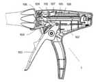
具体的には、本実施例では、図1、4~6に示すように、本発明の外科用ステープラー1は、制御手段100、中間コネクタ、及び実行手段を含む(これらのうち、中間コネクタ及び実行手段は従来の外科用ステープラーの一般的な構造形態であるため、具体的には示されていない)。制御手段100、中間コネクタ、及び実行手段の3つは順次接続される。実行手段は、ステープルアンビルユニット、ステーブルカートリッジユニット、及び駆動ユニットを含み、ステープルアンビルユニット及びステーブルカートリッジユニットは、開放と閉鎖の状態の間で移動可能なジョーを構成し、駆動ユニットはジョーを開放・閉合制御し、ステーブルカートリッジ内に置かれた吻合ステープルを押し出し、ステープルアンビルの組織接触面で成形させる。 Specifically, in this embodiment, as shown in FIGS. 1, 4 to 6, the
図1~6に示すうように、制御手段100は、左側ハウジング101、右側ハウジング102、ステープリングトリガー103、セキュリティトリガー104、駆動歯105、ラック106、ラック制限スライダ107、引張りばね108、ステープリング抑制ブロック109、弾性シート110を含む。 As shown in FIGS. 1 to 6, the control means 100 includes a
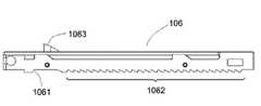
ステープリングトリガー103は、左側ハウジング101と右側ハウジング102の内部に部分的に配置され、固定回転軸を中心に回動可能である。ステープリングトリガー103には、可動回転軸を中心に回動可能な駆動歯105が取り付けられ、駆動歯105はラック106の第1組の歯1061又は第2組の歯1062と分離可能に嵌合する。 The
図7、9~10に示すように、ステープリング抑制ブロック109には円状孔1091(図7)を有し、該円状孔1091は、左側ハウジング101に位置するカラム1011と嵌合し、カラム1011に沿って一定の角度で回転運動が可能である(図10)。弾性シート110は、-端がステープリング抑制ブロック109に作用し、他端が左側ハウジング101に作用し、弾性シート110は、ステープリング抑制ブロック109に位置する遮断構造1093をラック106の第2組の歯1062から離れる方向へ付勢することができる(図9)。 As shown in FIGS. 7 and 9 to 10, the
別の実施例では、ステープリング抑制ブロック109は、ガイドレールに沿って、ラック106の第2組の歯1062から離れた方向に摺動することができ、弾性シート110は、ばね、ねじりばねや他の弾性部品としてもよく、左側ハウジング101、右側ハウジング102、又は他の部品に作用する。 In another embodiment, the stapling
図8に示すように、ラック制限スライダ107は、ステープリング抑制ブロック109の傾斜面1092(図7、図10)と互いに嵌合するボス1071を有する(図8)。 As shown in FIG. 8, the
本実施例の操作は具体的には以下のとおりである。図4に示すように、操作ステープリングトリガー103は一定の角度だけ回動し、ステープリングトリガー103上で回動可能な駆動歯105はラック106の第1組の歯1061と組み合わせて、ラック106を所定距離だけ前進させる。ラック106には、ラック制限スライダ107と離脱可能に接続されたボス1063を有し、ボス1063はラック制限スライド107に配置されたボス1072と作用し、ラック制限スライダ107を前進させる。ラック制限スライダ107は、側面のボス1071をもってステープリング抑制ブロック109の傾斜面1092と接触し、ステープリング抑制ブロック109が弾性シート110の弾性力に抗して回転するようにし、ステープリング抑制ブロック109が一定の角度回転すると、遮断構造1093はラック106の第2組の歯1062を遮断する。 Specifically, the operation of this embodiment is as follows. As shown in FIG. 4, the
図5に示すように、ステープリングトリガー103が解放されると、駆動歯105はラック106の第1組の歯1061とは嵌合を解除する。駆動ユニットとステーブルカートリッジユニット及びステープルアンビルユニットとの摩擦力が、引張りばね108に貯蔵されたエネルギーよりも大きい場合、引張りばね108はラック制限スライダ107によってラック106を元の位置に引くことができず、前記ジョーが開放できなくなるときに、ステープリングトリガー103が再度操作されると、ステープリング抑制ブロック109の遮断構造1093によりラック106の第2組の歯1062が遮断されるため、駆動歯105はラック106の第2組の歯1062と嵌合できず、ラック106を前進させることができない。 As shown in FIG. 5, when the
図6に示すように、セキュリティトリガー104が操作されると、ラック制限スライダ107はラック106と嵌合を解除して、元の位置に戻る。このとき、ラック制限スライダ107のボス1071はステープリング抑制ブロック109の傾斜面1092と接触しなくなり、ステープリング抑制ブロック109は弾性シート110の作用によって、遮断構造1093がラック106の第2組の歯1062から離れる。ステープリングトリガー103が再度操作されると、駆動歯105はラック106の第2組の歯1062と嵌合して、ラック106を前進させ、切断や縫合を行う。 As shown in FIG. 6, when the
本発明の特定実施形態を例示して説明したが、当業者にとっては、本発明の原理及び主旨を逸脱することなく、これらの特定実施形態に対して、複数種の変化、修正、置換及び変形を行うことができ、本発明の範囲は添付の特許請求の範囲及びその同等物により定められる。 Although the specific embodiments of the present invention have been exemplified and described, those skilled in the art will have a plurality of changes, modifications, substitutions and modifications to these specific embodiments without departing from the principles and gist of the present invention. And the scope of the invention is defined by the appended claims and their equivalents.
Claims (12)
Translated fromJapanese前記実行手段、中間コネクタ、制御手段は順次接続され、
前記制御手段は、ハウジング、ハウジング内に配置又は部分的に配置された駆動機構、セキュリティ機構を含む手術器具であって、
前記セキュリティ機構は、セキュリティトリガー、ステープリング抑制ブロック、及びオフセット構造を含む、ことを特徴とする手術器具。Includes execution means, intermediate connectors, and control means
The execution means, the intermediate connector, and the control means are sequentially connected, and the execution means, the intermediate connector, and the control means are sequentially connected.
The control means is a surgical instrument including a housing, a drive mechanism arranged or partially arranged within the housing, and a security mechanism.
The surgical instrument comprising the security mechanism, a security trigger, a stapling suppression block, and an offset structure.
前記オフセット構造はステープリング抑制ブロックが前記ラックから離れるようにし、前記セキュリティ機構がオンにされていない場合、前記ステープリング抑制ブロックは前記駆動歯と前記ラックとの嵌合を制限する、ことを特徴とする請求項1に記載の手術器具。The drive mechanism includes a stapling trigger and drive teeth and racks located on the stapling trigger.
The offset structure is characterized in that the stapling suppression block is separated from the rack and, when the security mechanism is not turned on, the stapling suppression block limits the fit of the drive teeth to the rack. The surgical instrument according to claim 1.
前記オフセット構造はステープリング抑制ブロックが前記ラックの第2組の歯から離れるようにし、前記セキュリティ機構がオンにされていない場合、前記ステープリング抑制ブロックは前記駆動歯と前記第2組の歯との嵌合を制限する、ことを特徴とする請求項2に記載の手術器具。The rack contains a first set of teeth and a second set of teeth.
The offset structure ensures that the stapling suppression block is separated from the second set of teeth in the rack, and when the security mechanism is not turned on, the stapling suppression block comprises the driving teeth and the second set of teeth. The surgical instrument according to claim 2, wherein the fitting of the surgical instrument is restricted.
前記自動回復機構はラック制限スライダを含み、
前記ステープリングトリガーが操作されると、前記ラックは前記ラック制限スライダを前進駆動し、ラック制限スライダが前記オフセット構造による力に抗して移動するまでステープリング抑制ブロックを押すと、前記ステープリング抑制ブロックは前記駆動歯と前記第2組の歯との嵌合を制限する、ことを特徴とする請求項3に記載の手術器具。Including automatic recovery mechanism
The auto-recovery mechanism includes a rack limit slider.
When the stapling trigger is operated, the rack drives the rack limiting slider forward and pushes the stapling suppression block until the rack limiting slider moves against the force of the offset structure to suppress the stapling. The surgical instrument according to claim 3, wherein the block limits the fitting of the driving tooth and the second set of teeth.
前記ステープリング抑制ブロックが前記ラック第2組の歯に接近する場合、前記遮断構造は前記ステープリング抑制ブロックに追従して移動し、前記ラックの第2組の歯を遮断し、前記ステープリング抑制ブロックが前記第2組の歯から離れる場合、前記遮断構造は前記第2組の歯に対する遮断を解除する、ことを特徴とする請求項3に記載の手術器具。The stapling suppression block includes a blocking structure and
When the stapling suppression block approaches the teeth of the second set of racks, the blocking structure moves following the stapling suppression block to block the second set of teeth of the rack and suppresses the stapling. The surgical instrument according to claim 3, wherein when the block separates from the second set of teeth, the blocking structure releases the blocking on the second set of teeth.
Applications Claiming Priority (3)
| Application Number | Priority Date | Filing Date | Title |
|---|---|---|---|
| CN201811589772.8 | 2018-12-25 | ||
| CN201811589772.8ACN109674500B (en) | 2018-12-25 | 2018-12-25 | A safety device for surgical instruments |
| PCT/CN2019/126973WO2020135253A1 (en) | 2018-12-25 | 2019-12-20 | Safety device for surgical instrument |
Publications (1)
| Publication Number | Publication Date |
|---|---|
| JP2022517310Atrue JP2022517310A (en) | 2022-03-08 |
Family
ID=66189378
Family Applications (1)
| Application Number | Title | Priority Date | Filing Date |
|---|---|---|---|
| JP2021537139APendingJP2022517310A (en) | 2018-12-25 | 2019-12-20 | Surgical instrument security device |
Country Status (6)
| Country | Link |
|---|---|
| US (1) | US20220061949A1 (en) |
| EP (1) | EP3903693A4 (en) |
| JP (1) | JP2022517310A (en) |
| CN (1) | CN109674500B (en) |
| BR (1) | BR112021012565A2 (en) |
| WO (1) | WO2020135253A1 (en) |
Families Citing this family (7)
| Publication number | Priority date | Publication date | Assignee | Title |
|---|---|---|---|---|
| CN109674500B (en)* | 2018-12-25 | 2024-04-02 | 上海逸思医疗科技股份有限公司 | A safety device for surgical instruments |
| US11871925B2 (en)* | 2020-07-28 | 2024-01-16 | Cilag Gmbh International | Surgical instruments with dual spherical articulation joint arrangements |
| CN111870296B (en)* | 2020-08-31 | 2025-06-24 | 山东威瑞外科医用制品有限公司 | A stapler |
| CN115363661B (en)* | 2021-05-19 | 2024-11-01 | 欣格誉科技(无锡)有限公司 | Driving mechanism for anastomat |
| USD1024324S1 (en)* | 2021-08-11 | 2024-04-23 | Ezisurg Medical Co., Ltd. | Handle for surgical instrument |
| CN115462851B (en)* | 2022-08-26 | 2025-04-11 | 逸思(苏州)医疗科技有限公司 | Safety device for surgical instruments and laparoscopic stapler |
| USD1092737S1 (en)* | 2023-11-17 | 2025-09-09 | Alexis Delobaux | Surgical instrument |
Citations (1)
| Publication number | Priority date | Publication date | Assignee | Title |
|---|---|---|---|---|
| US20180116676A1 (en)* | 2016-11-01 | 2018-05-03 | Covidien Lp | Endoscopic surgical clip applier |
Family Cites Families (25)
| Publication number | Priority date | Publication date | Assignee | Title |
|---|---|---|---|---|
| US5356064A (en)* | 1991-10-18 | 1994-10-18 | United States Surgical Corporation | Apparatus and method for applying surgical staples to attach an object to body tissue |
| US5289963A (en)* | 1991-10-18 | 1994-03-01 | United States Surgical Corporation | Apparatus and method for applying surgical staples to attach an object to body tissue |
| GR1002336B (en)* | 1992-05-06 | 1996-05-21 | Ethicon Inc. | Endoscopic surgical apparatus capable of ligation and division. |
| US5607436A (en)* | 1993-10-08 | 1997-03-04 | United States Surgical Corporation | Apparatus for applying surgical clips |
| US5865361A (en)* | 1997-09-23 | 1999-02-02 | United States Surgical Corporation | Surgical stapling apparatus |
| US6569171B2 (en)* | 2001-02-28 | 2003-05-27 | Microline, Inc. | Safety locking mechanism for a medical clip device |
| GB0020263D0 (en)* | 2000-08-18 | 2000-10-04 | Femcare Cyprus Ltd | Improvements in or relating to applicators |
| US6551333B2 (en)* | 2000-10-19 | 2003-04-22 | Ethicon Endo-Surgery, Inc. | Method for attaching hernia mesh |
| US6959852B2 (en)* | 2003-09-29 | 2005-11-01 | Ethicon Endo-Surgery, Inc. | Surgical stapling instrument with multistroke firing incorporating an anti-backup mechanism |
| CN100394892C (en)* | 2005-01-26 | 2008-06-18 | 苏州天臣国际医疗科技有限公司 | Surgical binding instrument |
| US7686820B2 (en)* | 2005-04-14 | 2010-03-30 | Ethicon Endo-Surgery, Inc. | Surgical clip applier ratchet mechanism |
| US20070049950A1 (en)* | 2005-08-25 | 2007-03-01 | Microline Pentax Inc. | Medical clip applying device |
| US8267944B2 (en)* | 2008-08-29 | 2012-09-18 | Tyco Healthcare Group Lp | Endoscopic surgical clip applier with lock out |
| US8403945B2 (en)* | 2010-02-25 | 2013-03-26 | Covidien Lp | Articulating endoscopic surgical clip applier |
| CN103767751B (en) | 2014-01-03 | 2016-02-24 | 上海逸思医疗科技有限公司 | A kind of surgical instruments of one-hand operation |
| CN103767752B (en)* | 2014-01-03 | 2016-02-03 | 上海逸思医疗科技有限公司 | A kind of surgical instruments of safety one-hand operation |
| CN105433999B (en)* | 2014-07-23 | 2017-07-14 | 瑞奇外科器械(中国)有限公司 | The safeties and surgical operating instrument of surgical operating instrument |
| CN104622529B (en)* | 2015-02-15 | 2016-09-21 | 江苏孜航精密五金有限公司 | A kind of clamping safety for intracavity stiching instrument |
| CN105167814A (en)* | 2015-08-14 | 2015-12-23 | 上海逸思医疗科技有限公司 | Surgery equipment with one-hand operated safety device and operation method thereof |
| CN104997541A (en)* | 2015-08-14 | 2015-10-28 | 上海逸思医疗科技有限公司 | One-hand operable surgical instrument and operation method thereof |
| CN205307029U (en)* | 2015-08-14 | 2016-06-15 | 上海逸思医疗科技有限公司 | Surgical instrument capable of being operated by signal hand |
| US10390831B2 (en)* | 2015-11-10 | 2019-08-27 | Covidien Lp | Endoscopic reposable surgical clip applier |
| CN108852445A (en)* | 2018-09-06 | 2018-11-23 | 苏州法兰克曼医疗器械有限公司 | A kind of surgical operating instrument with insurance institution |
| CN109674500B (en)* | 2018-12-25 | 2024-04-02 | 上海逸思医疗科技股份有限公司 | A safety device for surgical instruments |
| CN209450590U (en)* | 2018-12-25 | 2019-10-01 | 上海逸思医疗科技有限公司 | A safety device for surgical instruments |
- 2018
- 2018-12-25CNCN201811589772.8Apatent/CN109674500B/enactiveActive
- 2019
- 2019-12-20USUS17/418,002patent/US20220061949A1/ennot_activeAbandoned
- 2019-12-20WOPCT/CN2019/126973patent/WO2020135253A1/ennot_activeCeased
- 2019-12-20BRBR112021012565-5Apatent/BR112021012565A2/ennot_activeApplication Discontinuation
- 2019-12-20JPJP2021537139Apatent/JP2022517310A/enactivePending
- 2019-12-20EPEP19903405.9Apatent/EP3903693A4/ennot_activeWithdrawn
Patent Citations (1)
| Publication number | Priority date | Publication date | Assignee | Title |
|---|---|---|---|---|
| US20180116676A1 (en)* | 2016-11-01 | 2018-05-03 | Covidien Lp | Endoscopic surgical clip applier |
Also Published As
| Publication number | Publication date |
|---|---|
| BR112021012565A2 (en) | 2021-09-14 |
| CN109674500B (en) | 2024-04-02 |
| EP3903693A1 (en) | 2021-11-03 |
| EP3903693A4 (en) | 2022-09-14 |
| CN109674500A (en) | 2019-04-26 |
| WO2020135253A1 (en) | 2020-07-02 |
| US20220061949A1 (en) | 2022-03-03 |
Similar Documents
| Publication | Publication Date | Title |
|---|---|---|
| JP2022517310A (en) | Surgical instrument security device | |
| CN112888378B (en) | Articulatable motor-powered surgical instrument with dedicated articulation motor arrangement | |
| JP7504870B2 (en) | Surgical instrument having progressive jaw closure configuration | |
| JP4703978B2 (en) | Surgical stapler with firing lockout against unclosed anvil | |
| US10226255B2 (en) | Medical anastomosis device | |
| JP2021533930A (en) | Switching configuration for motorized range of motion surgical instruments | |
| EP3431018B1 (en) | Surgical stapler with expandable jaw | |
| EP1495726B1 (en) | Surgical stapling instrument incorporating an articulation joint for a firing bar track | |
| CN104688288B (en) | Medical stapler | |
| CN218528805U (en) | Platform components and staplers | |
| CN218356278U (en) | Platform assembly and anastomat | |
| CN104997541A (en) | One-hand operable surgical instrument and operation method thereof | |
| CN217907878U (en) | Platform assembly and anastomat | |
| US11337695B2 (en) | Staple cartridge assembly and medical stapler using the staple cartridge assembly | |
| WO2017028362A1 (en) | Surgical instrument having single-handed-operation safety device, and operation method thereof | |
| WO2020228600A1 (en) | Medical device | |
| CN204708912U (en) | Medical stapler | |
| CN103767752A (en) | Surgical instrument with safety device capable of being operated with single hand | |
| CN114680993A (en) | clamp applier | |
| CN114680995B (en) | A clip applier | |
| CN114680999B (en) | Clip Applier | |
| CN204562255U (en) | Medical stapler | |
| CN114680994A (en) | a clamp | |
| CN210903169U (en) | Medical instrument | |
| CN218684549U (en) | Platform components and staplers |
Legal Events
| Date | Code | Title | Description |
|---|---|---|---|
| A621 | Written request for application examination | Free format text:JAPANESE INTERMEDIATE CODE: A621 Effective date:20221110 | |
| A977 | Report on retrieval | Free format text:JAPANESE INTERMEDIATE CODE: A971007 Effective date:20230824 | |
| A131 | Notification of reasons for refusal | Free format text:JAPANESE INTERMEDIATE CODE: A131 Effective date:20230829 | |
| A02 | Decision of refusal | Free format text:JAPANESE INTERMEDIATE CODE: A02 Effective date:20240326 |