JP2022516367A - Infrared heating aerosol generator - Google Patents
Infrared heating aerosol generatorDownload PDFInfo
- Publication number
- JP2022516367A JP2022516367AJP2021539537AJP2021539537AJP2022516367AJP 2022516367 AJP2022516367 AJP 2022516367AJP 2021539537 AJP2021539537 AJP 2021539537AJP 2021539537 AJP2021539537 AJP 2021539537AJP 2022516367 AJP2022516367 AJP 2022516367A
- Authority
- JP
- Japan
- Prior art keywords
- aerosol
- forming substrate
- radiation
- generating element
- receptacle
- Prior art date
- Legal status (The legal status is an assumption and is not a legal conclusion. Google has not performed a legal analysis and makes no representation as to the accuracy of the status listed.)
- Pending
Links
Images


Classifications
- A—HUMAN NECESSITIES
- A24—TOBACCO; CIGARS; CIGARETTES; SIMULATED SMOKING DEVICES; SMOKERS' REQUISITES
- A24B—MANUFACTURE OR PREPARATION OF TOBACCO FOR SMOKING OR CHEWING; TOBACCO; SNUFF
- A24B15/00—Chemical features or treatment of tobacco; Tobacco substitutes, e.g. in liquid form
- A24B15/10—Chemical features of tobacco products or tobacco substitutes
- A24B15/16—Chemical features of tobacco products or tobacco substitutes of tobacco substitutes
- A24B15/167—Chemical features of tobacco products or tobacco substitutes of tobacco substitutes in liquid or vaporisable form, e.g. liquid compositions for electronic cigarettes
- A—HUMAN NECESSITIES
- A24—TOBACCO; CIGARS; CIGARETTES; SIMULATED SMOKING DEVICES; SMOKERS' REQUISITES
- A24F—SMOKERS' REQUISITES; MATCH BOXES; SIMULATED SMOKING DEVICES
- A24F1/00—Tobacco pipes
- A24F1/30—Hookahs
- A—HUMAN NECESSITIES
- A24—TOBACCO; CIGARS; CIGARETTES; SIMULATED SMOKING DEVICES; SMOKERS' REQUISITES
- A24F—SMOKERS' REQUISITES; MATCH BOXES; SIMULATED SMOKING DEVICES
- A24F40/00—Electrically operated smoking devices; Component parts thereof; Manufacture thereof; Maintenance or testing thereof; Charging means specially adapted therefor
- A24F40/20—Devices using solid inhalable precursors
- A—HUMAN NECESSITIES
- A24—TOBACCO; CIGARS; CIGARETTES; SIMULATED SMOKING DEVICES; SMOKERS' REQUISITES
- A24F—SMOKERS' REQUISITES; MATCH BOXES; SIMULATED SMOKING DEVICES
- A24F40/00—Electrically operated smoking devices; Component parts thereof; Manufacture thereof; Maintenance or testing thereof; Charging means specially adapted therefor
- A24F40/40—Constructional details, e.g. connection of cartridges and battery parts
- A24F40/46—Shape or structure of electric heating means
- A24F40/465—Shape or structure of electric heating means specially adapted for induction heating
- H—ELECTRICITY
- H05—ELECTRIC TECHNIQUES NOT OTHERWISE PROVIDED FOR
- H05B—ELECTRIC HEATING; ELECTRIC LIGHT SOURCES NOT OTHERWISE PROVIDED FOR; CIRCUIT ARRANGEMENTS FOR ELECTRIC LIGHT SOURCES, IN GENERAL
- H05B11/00—Heating by combined application of processes covered by two or more of groups H05B3/00 - H05B7/00
- H—ELECTRICITY
- H05—ELECTRIC TECHNIQUES NOT OTHERWISE PROVIDED FOR
- H05B—ELECTRIC HEATING; ELECTRIC LIGHT SOURCES NOT OTHERWISE PROVIDED FOR; CIRCUIT ARRANGEMENTS FOR ELECTRIC LIGHT SOURCES, IN GENERAL
- H05B3/00—Ohmic-resistance heating
- H05B3/02—Details
- H05B3/06—Heater elements structurally combined with coupling elements or holders
- H—ELECTRICITY
- H05—ELECTRIC TECHNIQUES NOT OTHERWISE PROVIDED FOR
- H05B—ELECTRIC HEATING; ELECTRIC LIGHT SOURCES NOT OTHERWISE PROVIDED FOR; CIRCUIT ARRANGEMENTS FOR ELECTRIC LIGHT SOURCES, IN GENERAL
- H05B6/00—Heating by electric, magnetic or electromagnetic fields
- H05B6/02—Induction heating
- H05B6/10—Induction heating apparatus, other than furnaces, for specific applications
- H05B6/105—Induction heating apparatus, other than furnaces, for specific applications using a susceptor
Landscapes
- Chemical & Material Sciences (AREA)
- Chemical Kinetics & Catalysis (AREA)
- General Chemical & Material Sciences (AREA)
- Physics & Mathematics (AREA)
- Electromagnetism (AREA)
- Radiation-Therapy Devices (AREA)
- Resistance Heating (AREA)
Abstract
Translated fromJapaneseDescription
Translated fromJapanese本発明は、シーシャ装置でエアロゾルを発生するためのエアロゾル発生要素に関する。より具体的には、本開示は、エアロゾル発生要素に関し、エアロゾルは、赤外線(IR)放射によってエアロゾル形成基体を加熱することを介して発生する。本発明はさらに、エアロゾル発生要素を備えるシーシャ装置、シーシャ装置およびエアロゾル発生物品の両方を備えるエアロゾル発生システム、およびシーシャ装置でエアロゾルを形成するための方法に関する。 The present invention relates to an aerosol generating element for generating an aerosol in a shisha device. More specifically, the present disclosure relates to aerosol generating elements, where the aerosol is generated through heating the aerosol-forming substrate with infrared (IR) radiation. The present invention further relates to a shisha device comprising an aerosol generating element, an aerosol generating system comprising both a shisha device and an aerosol generating article, and a method for forming an aerosol in the shisha device.
従来のシーシャ装置は、たばこ基体を喫煙するために使用されていて、またユーザーによって吸入される前にベイパーおよび煙が水盤を通過するように構成されている。シーシャ装置は、一つの出口を含んでもよく、または二人以上のユーザーが同時に装置を使用することができるように二つ以上の出口を含んでもよい。シーシャ装置の使用は、多くの人によって娯楽活動および社交体験であると考えられている。 Traditional shisha devices have been used to smoke tobacco substrates and are configured to allow vapors and smoke to pass through the basin before being inhaled by the user. The shisha device may include one outlet, or may include two or more outlets so that two or more users can use the device at the same time. The use of shisha appliances is considered by many to be an entertaining and social experience.
従来のシーシャ装置は、たばこ基体を加熱または燃焼して、ユーザーによる吸入のためにエアロゾルを発生させるために木炭を用いる。高レベルの一酸化炭素および多環式芳香族炭化水素などの望ましくない燃焼副産物、ならびに他の有害および有害である可能性がある成分が、従来のシーシャ装置の使用中に生成される場合がある。一酸化炭素は、木炭だけでなくたばこ基体の燃焼によって発生し得る。 Traditional shisha devices use charcoal to heat or burn a tobacco substrate to generate an aerosol for user inhalation. Unwanted combustion by-products such as high levels of carbon monoxide and polycyclic aromatic hydrocarbons, as well as other harmful and potentially harmful components, may be produced during the use of conventional shisha equipment. .. Carbon monoxide can be generated by burning tobacco substrates as well as charcoal.
一酸化炭素および燃焼副産物の生成を減少させる一つの方法は、基体を燃焼することなく基体からエアロゾルを生成するために十分な温度にたばこ基体を加熱する電気ヒーター、例えば、抵抗ヒーターを木炭の代わりに使用することである。 One way to reduce the production of carbon monoxide and combustion by-products is to replace charcoal with an electric heater, such as a resistance heater, that heats the tobacco substrate to a temperature sufficient to produce aerosols from the substrate without burning the substrate. Is to be used for.
しかしながら、従来の木炭で作動するシーシャ装置と比較して、電気加熱式装置は、総エアロゾル質量の低下、可視エアロゾルの低下、エアロゾル体積の低下、またはそれらの任意の組み合わせに悩まされる場合がある。これらのエアロゾル特性のうちの一つ以上の減少は、基体と加熱される表面との間の接触が不良であるために、最初の吸煙中に特に顕著であり得る。結果として、最初の吸煙が消費のために利用可能になるまで基体を加熱するのにかかる時間(TT1P)は、従来の木炭加熱式シーシャ装置と比較して比較的長くなり得る。 However, compared to traditional charcoal-operated shisha devices, electrically heated devices may suffer from reduced total aerosol mass, reduced visible aerosols, reduced aerosol volume, or any combination thereof. A decrease in one or more of these aerosol properties can be particularly pronounced during initial smoke absorption due to poor contact between the substrate and the surface to be heated. As a result, the time it takes to heat the substrate (TT1P) until the first smoke absorption is available for consumption can be relatively long compared to conventional charcoal-heated shisha devices.
同時に、従来のシーシャでは、木炭は、エアロゾル形成基体全体を同時かつ均等に加熱しないため、独特の加熱特性を提供する。木炭を所望のペースで異なる地点に移動させることは、従来のシーシャの慣例および喫煙体験の重要な部分である。 At the same time, in conventional shisha, charcoal does not heat the entire aerosol-forming substrate simultaneously and evenly, thus providing unique heating properties. Moving charcoal to different points at the desired pace is an important part of traditional shisha practices and smoking experiences.
従来の木炭シーシャ装置と比較して、一酸化炭素および望ましくない燃焼副産物の生成を減少させるシーシャ装置を提供することが望ましい。 It is desirable to provide a shisha device that reduces the production of carbon monoxide and unwanted combustion by-products as compared to conventional charcoal shisha devices.
従来のシーシャの慣例および喫煙体験に一致する、似ている、またはこれらを模倣する加熱特性を有するシーシャ装置を提供することが望ましい。 It is desirable to provide a shisha device with heating properties that are consistent with, similar to, or mimicking traditional shisha practices and smoking experiences.
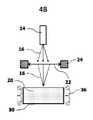
本発明の様々な態様において、シーシャ装置でエアロゾルを発生するためのエアロゾル発生要素が提供されている。エアロゾル発生要素は、エアロゾル形成基体を受けるためのレセプタクルと、IR放射のビームを発生するように構成されたフォトニック装置とを備える。エアロゾル発生要素は、IR放射のビームをエアロゾル形成基体上に方向付けることによってエアロゾル形成基体を加熱するように配設される。 In various aspects of the invention, aerosol generating elements for generating aerosols in shisha devices are provided. The aerosol-generating element comprises a receptacle for receiving the aerosol-forming substrate and a photonic device configured to generate a beam of IR radiation. The aerosol generating element is arranged to heat the aerosol-forming substrate by directing a beam of IR radiation onto the aerosol-forming substrate.
したがって、フォトニック装置は、IRエミッタとして作用する。概して、本発明のエアロゾル発生要素は、IR放射を使用してエアロゾル形成基体の一つ以上の構成要素を加熱する。一部の実施形態では、後で説明するように、エアロゾル形成基体はたばこを含み得る。 Therefore, the photonic device acts as an IR emitter. In general, the aerosol-generating elements of the invention use IR radiation to heat one or more components of the aerosol-forming substrate. In some embodiments, the aerosol-forming substrate may include tobacco, as described below.
したがって、本発明のエアロゾル発生要素は、エアロゾル形成基体がIR放射の吸収によって加熱される代替的な加熱システムを提供する。IR放射による加熱は、高速で、柔軟性のある効率的な加熱という利点をもたらす。 Accordingly, the aerosol-generating elements of the present invention provide an alternative heating system in which the aerosol-forming substrate is heated by absorption of IR radiation. Heating with IR radiation provides the advantage of fast, flexible and efficient heating.
伝導または対流とは対照的に、放射は、電磁波を介してエネルギーを伝達する。結果として、媒体または「熱担体」の有無に対する要件はない。これは、エアロゾル形成基体を所望の温度にするのに必要な時間の短縮に役立ち得る。これは、エアロゾル形成基体を予熱する期間中に特に有益であり得る。さらに、エアロゾル発生要素とエアロゾル形成基体との間の物理的接触は必要とされない。本発明のエアロゾル発生要素は、エアロゾル形成基体の非接触加熱を可能にする。 In contrast to conduction or convection, radiation transfers energy through electromagnetic waves. As a result, there are no requirements for the presence or absence of media or "heat carriers". This can help reduce the time required to bring the aerosol-forming substrate to the desired temperature. This can be particularly beneficial during the period of preheating the aerosol-forming substrate. Moreover, no physical contact is required between the aerosol generating element and the aerosol forming substrate. The aerosol generating element of the present invention enables non-contact heating of an aerosol-forming substrate.
エアロゾル発生要素は、エアロゾル形成基体と使用されてエアロゾルを生成し得る。具体的には、エアロゾル発生要素は、エアロゾル形成基体を受けて加熱してエアロゾルを発生させ得る。エアロゾル形成基体は、エアロゾル発生要素によって加熱されるが、燃焼されない場合がある。エアロゾル発生要素は発熱体を含んでもよい。発熱体は電気発熱体を含み得る。 Aerosol-generating elements can be used with aerosol-forming substrates to produce aerosols. Specifically, the aerosol-generating element may receive and heat an aerosol-forming substrate to generate an aerosol. The aerosol-forming substrate is heated by the aerosol-generating element, but may not be burned. The aerosol generating element may include a heating element. The heating element may include an electric heating element.
一部の実施形態では、エアロゾル発生要素は、エアロゾル形成基体を受けるためのレセプタクル、レセプタクルを覆うためのカバープレート、エアロゾル形成基体を含むカートリッジ、カートリッジを覆うための箔、およびエアロゾル形成基体を加熱するための少なくとも一つの木炭のペレットのうちのいずれかなど、従来のシーシャ装置の特徴を含み得る。 In some embodiments, the aerosol-generating element heats a receptacle for receiving the aerosol-forming substrate, a cover plate for covering the aerosol-forming substrate, a cartridge containing the aerosol-forming substrate, a foil for covering the cartridge, and an aerosol-forming substrate. It may include features of a conventional aerosol device, such as any one of at least one charcoal pellet for.
異なる材料は、異なる周波数でIR放射を吸収する。波長を注意深く選択することにより、他の物質は実質的に低温のままとしながら、特定の物質を効率的に加熱することが促進され得る。したがって、本発明のエアロゾル発生要素は、エアロゾル形成基体の一つ以上の構成要素の機能として標的加熱を可能にする。標的IR放射は、必ずしも周囲空気を加熱しない。これは、より効率的な加熱が達成され得ることを意味する。また、エアギャップは従来の電気加熱式シーシャシステムにおけるように大きな熱損失を引き起こさないため、より多くの設計の自由度が得られる。したがって、絶縁材料を必要とする可能性は低い。 Different materials absorb IR radiation at different frequencies. Careful selection of wavelengths can facilitate the efficient heating of certain substances while leaving others substantially cold. Accordingly, the aerosol-generating elements of the present invention allow target heating as a function of one or more components of the aerosol-forming substrate. Target IR radiation does not necessarily heat the ambient air. This means that more efficient heating can be achieved. In addition, the air gap does not cause large heat loss as in conventional electrically heated shisha systems, providing more design freedom. Therefore, it is unlikely that an insulating material will be needed.
IRビームを操作して、エアロゾル形成基体の特定の部分のみを照射することができる。また、IR吸収が低い透過率を有することは公知である。IRビームは、エアロゾル形成基体の照射された部分のみを加熱することを可能にする。したがって、本発明のエアロゾル発生要素は、空間の関数としての標的加熱を可能にする。 The IR beam can be manipulated to irradiate only certain parts of the aerosol-forming substrate. It is also known that IR absorption has a low transmittance. The IR beam makes it possible to heat only the irradiated portion of the aerosol-forming substrate. Therefore, the aerosol generating element of the present invention allows target heating as a function of space.
本発明のIR加熱手段の別の利点は、高速の熱応答である。エアロゾル形成基体は、実質的に照射時間の間だけ加熱され得る。 Another advantage of the IR heating means of the present invention is the fast thermal response. The aerosol-forming substrate can be heated substantially only during the irradiation time.
また、IR加熱は、IRエミッタおよび基体の空間配設に対して高い柔軟性を提供する。これは、エアロゾル発生要素およびシーシャ装置の幾何学的設計に対して広範なオプションを提供する。 IR heating also provides high flexibility for the spatial arrangement of the IR emitter and substrate. It offers a wide range of options for the geometric design of aerosol generators and shisha devices.
一部の実施形態では、IRビームは、フォトニック装置とエアロゾル形成基体との間で操作を受け得る。一部の実施形態では、IRビームの操作は、光学素子によって促進されることが好ましい。 In some embodiments, the IR beam can be manipulated between the photonic device and the aerosol forming substrate. In some embodiments, the manipulation of the IR beam is preferably facilitated by an optical element.
一部の実施形態では、エアロゾル発生要素は、フォトニック装置とレセプタクルとの間に位置し、IR放射のビームを操作するように構成される光学素子をさらに備える。 In some embodiments, the aerosol generating element further comprises an optical element located between the photonic device and the receptacle and configured to manipulate a beam of IR radiation.
「IR放射のビームの操作」という用語は、IR放射のビームの光路の任意の変化を含み得る。例としては、IRビームを反射すること、IRビームを偏向すること、IRビームを収束すること、およびIRビームを広がることのうちのいずれかが挙げられる。 The term "manipulation of the beam of IR radiation" may include any change in the optical path of the beam of IR radiation. Examples include reflecting the IR beam, deflecting the IR beam, converging the IR beam, and spreading the IR beam.
「光学素子」という用語は、IR放射のビームを操作することができる任意の要素を含む。例としては、ミラー、湾曲ミラー、レンズ、凸状レンズ、および凹状レンズが挙げられる。凹状レンズは、IRビームを広げてIRビームのエネルギー密度を低下させ得る。こうした構成は、吸煙が行われない長い時間間隔の間、例えば、予熱段階または吸煙間において基体を所定の低温に維持するのに特に有用であり得る。凸状レンズは、IRビームを収束させてIRビームのエネルギー密度を増大させ得る。収束または集束ビームは、基体の特定の領域の急速な枯渇を可能にし得る。 The term "optical element" includes any element capable of manipulating the beam of IR radiation. Examples include mirrors, curved mirrors, lenses, convex lenses, and concave lenses. The concave lens can widen the IR beam and reduce the energy density of the IR beam. Such a configuration may be particularly useful for keeping the substrate at a predetermined low temperature during long time intervals during which no smoke is absorbed, for example during the preheating step or during smoke absorption. The convex lens can converge the IR beam and increase the energy density of the IR beam. Converging or focusing beams can allow rapid depletion of specific areas of the substrate.
一つ以上の実施形態によれば、本発明のエアロゾル発生要素の光学素子は、光学マウント上に配設され得る。光学マウントは、移動可能であってもよい。光学マウントの移動は、機械的、電気的、または電気機械的に実行され得る。移動は、任意の適切な手段によって達成され得る。例としては、ステッパーモーター、偏心ねじ、またはステッパーモーターおよび偏心ねじの両方が挙げられる。移動は、ユーザーによって手動で実行されてもよい。移動は、電子的に制御される構成要素によって自動的に実行されることが好ましい。 According to one or more embodiments, the optical element of the aerosol generating element of the present invention may be disposed on an optical mount. The optical mount may be movable. The movement of the optical mount can be performed mechanically, electrically, or electromechanically. Movement can be achieved by any suitable means. Examples include stepper motors, eccentric threads, or both stepper motors and eccentric threads. The move may be performed manually by the user. The movement is preferably performed automatically by electronically controlled components.
光学素子の位置は、使用中に光学マウントによって調節可能であってもよい。光学マウント上に配設された光学素子は、IR放射のビームを操作することを可能にする。光学マウント上に配設された光学素子は、IR放射のビームを動的に操作することを可能にする。 The position of the optics may be adjustable by an optical mount during use. Optical elements disposed on the optical mount allow the beam of IR radiation to be manipulated. Optical elements disposed on the optical mount allow the beam of IR radiation to be dynamically manipulated.
用語「移動可能な光学マウント」は、光学素子を入射IRビームに対して異なる位置または方向に移動させることを可能にする、任意の種類の光学素子のマウントを含む。それによって、光学素子によって行われるIRビームの操作は、移動可能な光学マウントを介して光学素子を移動させることによって変更され得る。 The term "movable optics mount" includes mounting any type of optics that allows the optics to be moved in different positions or directions with respect to the incident IR beam. Thereby, the manipulation of the IR beam performed by the optical element can be modified by moving the optical element via a movable optical mount.
「IR放射のビームを動的に操作する」という用語は、IR放射のビームが、シーシャ装置におけるエアロゾル発生要素の使用中に操作され得ることを意味する。 The term "dynamically manipulating the beam of IR radiation" means that the beam of IR radiation can be manipulated during the use of aerosol generating elements in the shisha device.
用語「使用中」は、ユーザーがシーシャ装置を動作させた任意の瞬間を指し得る。「使用中」は、シーシャ装置をスイッチオンした任意の瞬間を指し得る。「使用中」は、フォトニック装置に電力が供給された任意の瞬間を指し得る。「使用中」とは、吸煙中または吸煙間の瞬間を指し得る。 The term "in use" can refer to any moment when the user activates the shisha device. "In use" can refer to any moment when the shisha device is switched on. "In use" can refer to any moment when the photonic device is powered. "In use" can refer to the moment of smoking or between smoking.
IRビームの操作は、移動可能な光学マウントを介して実行されてもよい。機械的、電気的、または電気機械的な移動は、任意の適切な手段によって達成され得る。例としては、ステッパーモーター、偏心ねじ、圧電ねじ、またはそれらの組み合わせが挙げられる。移動は、ユーザーによって手動で実行されてもよい。移動は、電子的に制御される構成要素によって自動的に実行されることが好ましい。 The operation of the IR beam may be performed via a movable optical mount. Mechanical, electrical, or electromechanical movement can be achieved by any suitable means. Examples include stepper motors, eccentric threads, piezoelectric threads, or combinations thereof. The move may be performed manually by the user. The movement is preferably performed automatically by electronically controlled components.
概して、IRビームの動的操作の進行は、電子回路上で動作するコンピュータプログラムによって制御され得る。動的操作の一部または動的操作全体は、例えば、コンピュータプログラムに従って、自動的に制御されてもよい。コンピュータプログラムは、非一時的コンピュータ可読記憶媒体上に格納され得る。動的操作の一つ以上の態様は、ユーザーによって部分的または完全に制御可能であり得る。例えば、ユーザーは、動的操作のペースを制御し得る。ユーザーは、IRビームが誘導される基体の場所を制御し得る。例えば、ユーザーがコマンドを入力し、それによってIRビームを自身の好みに従って動的に操作することを可能にする手段が含まれ得る。こうした手段は、当業者に対して公知の任意の適切な手段であり得る。例は、ユーザーインターフェースを含む制御ユニットである。一部の実施形態では、ユーザーインターフェースは、電子、機械、または電気機械ユーザーインターフェース手段を含み得る。 In general, the progress of dynamic manipulation of the IR beam can be controlled by a computer program running on an electronic circuit. Part of the dynamic operation or the entire dynamic operation may be automatically controlled according to, for example, a computer program. Computer programs may be stored on non-temporary computer-readable storage media. One or more aspects of dynamic operation may be partially or completely controllable by the user. For example, the user may control the pace of dynamic operation. The user may control the location of the substrate on which the IR beam is directed. For example, it may include means that allow the user to enter commands and thereby dynamically manipulate the IR beam according to their own preferences. Such means may be any suitable means known to those of skill in the art. An example is a control unit that includes a user interface. In some embodiments, the user interface may include electronic, mechanical, or electromechanical user interface means.
IR放射のビームを動的に操作することは、ビームの軌道を動的に操作することを可能にし得る。それによって、IRビームの動的操作は、エアロゾル形成基体の異なる部分を照射することを可能にする。それによって、IRビームの動的操作は、エアロゾル形成基体の選択的な照射を可能にし、これにより選択的なエアロゾル発生を可能にし得る。IRビームの動的操作は、エアロゾル形成基体の逐次的な照射を可能にし得る。本発明のエアロゾル発生要素を用いて、エアロゾル形成基体の異なる部分が逐次的に加熱され得る。逐次的な加熱は、ユーザーによって部分的または完全に制御されてもよい。本発明のエアロゾル発生要素は、基体上の木炭の移動に似ていてもよく、喫煙経験の従来の慣例がさらに保持され得る。 Dynamically manipulating the beam of IR radiation may allow for dynamically manipulating the trajectory of the beam. Thereby, the dynamic manipulation of the IR beam makes it possible to irradiate different parts of the aerosol-forming substrate. Thereby, the dynamic manipulation of the IR beam may allow selective irradiation of the aerosol-forming substrate, thereby allowing selective aerosol generation. The dynamic manipulation of the IR beam may allow for sequential irradiation of the aerosol-forming substrate. Different parts of the aerosol-forming substrate can be sequentially heated using the aerosol-generating elements of the present invention. Sequential heating may be partially or completely controlled by the user. The aerosol generating element of the present invention may resemble the transfer of charcoal on a substrate, and the conventional practice of smoking experience may be further retained.
エアロゾル発生要素のフォトニック装置は、IRエミッタとして機能する。適切なIRエミッタを選択するためには、エアロゾル形成基体の組成を考慮するべきである。IRエミッタは、一つ以上のIRエミッタ特性を考慮して選択され得る。一つ以上のIRエミッタ特性は、エアロゾル形成基体の一つ以上の構成要素に応じて選択され得る。例えば、前述の一つ以上の電磁エミッタ特性は、波長、周波数、スポットサイズ、スウェプトソース、パルス対連続波、エネルギーおよび電力のうちの任意の一つまたはそれらの組み合わせを含み得る。例えば、IRエミッタの波長は、エアロゾル形成基体の一つ以上の構成要素によるIR光の吸収を考慮して選択され得る。IRエミッタの波長は、エアロゾル形成基体の一つ以上の構成要素によるIR光の透過を考慮して選択されてもよい。 The photonic device of the aerosol generating element functions as an IR emitter. The composition of the aerosol-forming substrate should be considered in order to select the appropriate IR emitter. The IR emitter may be selected in consideration of one or more IR emitter characteristics. One or more IR emitter properties may be selected depending on one or more components of the aerosol-forming substrate. For example, the one or more electromagnetic emitter properties described above may include any one or a combination of wavelength, frequency, spot size, swept source, pulse vs. continuous wave, energy and power. For example, the wavelength of the IR emitter may be selected in view of the absorption of IR light by one or more components of the aerosol-forming substrate. The wavelength of the IR emitter may be selected in consideration of the transmission of IR light by one or more components of the aerosol-forming substrate.
IRエミッタの波長は、エアロゾル形成基体の構成要素のIR吸収帯に対応し得る。IRエミッタの波長は、エアロゾル形成基体の二つ以上の構成要素のIR吸収帯に対応し得る。 The wavelength of the IR emitter may correspond to the IR absorption band of the components of the aerosol forming substrate. The wavelength of the IR emitter may correspond to the IR absorption band of two or more components of the aerosol forming substrate.
例えば、IRエミッタの波長は、後で説明するように、グリセロール、糖蜜、糖、転化糖、たばこ、たばこ誘導体、またはエアロゾル形成基体の任意の他の構成要素のうちの一つ以上のIR吸収帯に対応し得る。 For example, the wavelength of the IR emitter is one or more of the IR absorption bands of glycerol, molasses, sugar, invert sugar, tobacco, tobacco derivatives, or any other component of the aerosol-forming substrate, as described below. Can correspond to.
用語「波長」は、単一波長、複数の単一波長、波長の範囲、複数の波長の範囲、またはそれらの任意の組み合わせを指し得る。 The term "wavelength" can refer to a single wavelength, multiple single wavelengths, a range of wavelengths, a range of multiple wavelengths, or any combination thereof.
例えば、エアロゾル形成基体中に比較的大量のグリセロールが存在してもよく、波長要件がグリセロールの強い吸収帯に対して適合されてもよい。グリセロールの強いIR吸収帯は、1300ナノメートル~2000ナノメートルのIR光の波長で見い出される。したがって、IRエミッタは、800ナノメートル~2300ナノメートル、好ましくは1300ナノメートル~2000ナノメートルの範囲のIR光を放射し得る。 For example, a relatively large amount of glycerol may be present in the aerosol-forming substrate and wavelength requirements may be adapted for the strong absorption band of glycerol. A strong IR absorption band of glycerol is found at wavelengths of IR light from 1300 nanometers to 2000 nanometers. Therefore, the IR emitter may emit IR light in the range of 800 nanometers to 2300 nanometers, preferably 1300 nanometers to 2000 nanometers.
一部の実施形態では、IRエミッタは、0.1ワット~30ワット、好ましくは、0.5ワット~25ワット、より好ましくは、1ワット~20ワット、より好ましくは1ワット~3ワットの範囲の電力でIR光を放射し得る。一部の実施形態では、比較的高い電力が、エアロゾル形成基体を予熱するために使用される。一部の実施形態では、比較的低い電力が、要求に応じた吸煙に対して使用される。 In some embodiments, the IR emitter ranges from 0.1 watts to 30 watts, preferably 0.5 watts to 25 watts, more preferably 1 watts to 20 watts, more preferably 1 watts to 3 watts. IR light can be emitted with the power of. In some embodiments, relatively high power is used to preheat the aerosol-forming substrate. In some embodiments, relatively low power is used for smoke absorption on demand.
「要求に応じた吸煙」動作では、IRエミッタは、一回の吸煙に対するエアロゾルを発生するのに必要な最小量のエアロゾル形成基体を、5秒以内、好ましくは2秒以内、好ましくは1秒以内に最大摂氏250度にすることができなければならない。一回の吸煙に対してエアロゾルを発生するのに必要な最小量のエアロゾル形成基体は、最大1.2立方センチメートルであり得る。 In the "smoking on demand" operation, the IR emitter uses the minimum amount of aerosol-forming substrate required to generate an aerosol for a single smoke absorption within 5 seconds, preferably within 2 seconds, preferably within 1 second. Must be able to reach a maximum of 250 degrees Celsius. The minimum amount of aerosol-forming substrate required to generate an aerosol for a single smoke absorption can be up to 1.2 cubic centimeters.
一部の実施形態では、IR放射のビームのエネルギー密度は、0.010ワット/平方センチメートル~30ワット/平方センチメートル、好ましくは、0.050ワット/平方センチメートル~6ワット/平方センチメートル、より好ましくは、0.100ワット/平方センチメートル~3ワット/平方センチメートルの範囲であり得る。 In some embodiments, the energy density of the beam of IR radiation is 0.010 watts / square centimeter to 30 watts / square centimeter, preferably 0.050 watts / square centimeter to 6 watts / square centimeter, more preferably 0.100. It can range from watts / square centimeter to 3 watts / square centimeter.
一部の実施形態では、IR放射のビームの直径は、1ミリメートル~110ミリメートル、好ましくは、2ミリメートル~100ミリメートル、より好ましくは、5ミリメートル~80ミリメートルの範囲であり得る。概して、比較的大きな直径が、エアロゾル形成基体を予熱するために使用される。一部の実施形態では、比較的小さな直径が、要求に応じた吸煙に使用される。 In some embodiments, the diameter of the beam of IR radiation can range from 1 mm to 110 mm, preferably 2 mm to 100 mm, more preferably 5 mm to 80 mm. Generally, a relatively large diameter is used to preheat the aerosol-forming substrate. In some embodiments, a relatively small diameter is used for smoke absorption on demand.
「IRビームの直径」という用語は、IR放射のビームによって直接照射されるエアロゾル形成基体の領域の直径を指し得る。 The term "IR beam diameter" can refer to the diameter of the region of the aerosol-forming substrate that is directly irradiated by the beam of IR radiation.
IRエミッタとエアロゾル形成基体との間の距離は、最大30センチメートル、好ましくは最大20センチメートル、より好ましくは最大10センチメートルであり得る。 The distance between the IR emitter and the aerosol-forming substrate can be up to 30 centimeters, preferably up to 20 centimeters, more preferably up to 10 centimeters.
IRエミッタによるエアロゾル形成基体の加熱の強度に対する制御は、加熱の波長を既に選択したものからわずかに共振を外すよう動かすことによって達成され得る。これは有利なことに、エアロゾル形成基体の所望の化合物、例えばグリセロールの吸収を最大化し得る。一部の実施形態では、エアロゾル形成基体の加熱の強度に対する制御は、IRエミッタに供給される電力を変更することによって達成され得る。 Control of the heating intensity of the aerosol-forming substrate by the IR emitter can be achieved by moving the heating wavelength slightly out of resonance from the already selected one. This can advantageously maximize the absorption of the desired compound of the aerosol forming substrate, eg glycerol. In some embodiments, control over the heating intensity of the aerosol-forming substrate can be achieved by altering the power delivered to the IR emitter.
一部の実施形態では、IRエミッタは、レーザーを含み得る。一部の実施形態では、IRエミッタは、レーザーダイオードを含み得る。本発明のエアロゾル発生要素のフォトニック装置は、IRレーザーダイオードを含み得る。 In some embodiments, the IR emitter may include a laser. In some embodiments, the IR emitter may include a laser diode. The aerosol generating element photonic device of the present invention may include an IR laser diode.
本発明のフォトニック装置は、エアロゾル形成基体を加熱するための唯一の加熱手段として使用され得る。一部の実施形態では、本発明のフォトニック装置は、一つ以上の追加的な加熱手段と組み合わせて使用され得る。任意の加熱手段を、追加的な加熱手段として使用してもよい。例としては、抵抗加熱手段、誘導加熱手段、または抵抗加熱手段および誘導加熱手段の両方の組み合わせなどの、電気加熱手段が挙げられる。 The photonic apparatus of the present invention can be used as the only heating means for heating an aerosol-forming substrate. In some embodiments, the photonic apparatus of the invention can be used in combination with one or more additional heating means. Any heating means may be used as additional heating means. Examples include electric heating means, such as resistance heating means, induction heating means, or a combination of both resistance heating means and induction heating means.
一つ以上の実施形態では、エアロゾル発生要素は、レセプタクル内に受けられたエアロゾル形成基体を加熱するように構成された、電気加熱手段などの追加的な加熱手段を追加的に備えてもよい。追加的な電気加熱手段は、レセプタクルと熱接触してもよい。一つ以上の実施形態では、レセプタクルの少なくとも一部は、追加的な電気加熱手段によって形成されてもよい。 In one or more embodiments, the aerosol generating element may additionally comprise additional heating means, such as an electric heating means, configured to heat the aerosol-forming substrate received within the receptacle. Additional electrical heating means may be in thermal contact with the receptacle. In one or more embodiments, at least a portion of the receptacle may be formed by additional electrical heating means.
追加的な加熱手段は、抵抗加熱手段を含むことが好ましい。例えば、追加的な加熱手段は、一つ以上の抵抗性ワイヤーまたは他の抵抗性要素を含み得る。抵抗性ワイヤーは、熱伝導性材料と接触して、生成された熱をより広い区域にわたって分配してもよい。適切な導電性材料の例としては、アルミニウム、銅、亜鉛、ニッケル、銀、およびこれらの組み合わせが挙げられる。本開示の目的のために、抵抗性ワイヤーが熱伝導性材料と接触する場合、抵抗性ワイヤーと熱伝導性材料の両方は、レセプタクルの表面の少なくとも一部分を形成する加熱手段の一部である。 The additional heating means preferably includes resistance heating means. For example, additional heating means may include one or more resistant wires or other resistant elements. The resistant wire may be in contact with the thermally conductive material to distribute the generated heat over a wider area. Examples of suitable conductive materials include aluminum, copper, zinc, nickel, silver, and combinations thereof. For the purposes of the present disclosure, when the resistant wire comes into contact with the thermally conductive material, both the resistant wire and the thermally conductive material are part of the heating means forming at least a portion of the surface of the receptacle.
一部の実施例において、追加的な加熱手段は誘導加熱手段を含む。例えば、追加的な加熱手段は、レセプタクルの表面を形成するサセプタ材料を含み得る。本明細書で使用される「サセプタ」という用語は、電磁エネルギーを熱に変換する能力を有する材料を指す。交流電磁場中に位置する時、典型的にサセプタの中で渦電流が誘導され、かつヒステリシス損失が生じる場合があり、サセプタの加熱を生じさせる。サセプタがエアロゾル形成基体と熱的に接触して位置している、またはエアロゾル形成基体に熱的に近接近して位置していると、基体はサセプタによって加熱され、これによってエアロゾルが形成される。サセプタはエアロゾル形成基体またはエアロゾル形成基体を含有するカートリッジと少なくとも部分的に直接、物理的に接触して配設されていることが好ましい。 In some embodiments, additional heating means include induction heating means. For example, additional heating means may include a susceptor material that forms the surface of the receptacle. As used herein, the term "susceptor" refers to a material that has the ability to convert electromagnetic energy into heat. When located in an AC electromagnetic field, eddy currents are typically induced in the susceptor and hysteresis loss can occur, causing heating of the susceptor. When the susceptor is located in thermal contact with or in close proximity to the aerosol-forming substrate, the substrate is heated by the susceptor, thereby forming an aerosol. The susceptor is preferably disposed at least partially in direct physical contact with the aerosol-forming substrate or the cartridge containing the aerosol-forming substrate.
サセプタは、誘導加熱され得る任意の材料から形成されてもよい。サセプタは、エアロゾル形成基体からエアロゾルを発生させるのに十分な温度に誘導加熱され得る任意の材料から形成され得ることが好ましい。好ましいサセプタは金属または炭素を含む。好ましいサセプタは、強磁性材料(例えばフェライト鉄)、強磁性合金(強磁性鋼またはステンレス鋼など)、およびフェライトを含んでもよく、またはそれらから成ってもよい。適切なサセプタはアルミニウムであってもよく、またはアルミニウムを含んでもよい。 The susceptor may be formed from any material that can be induced heated. It is preferred that the susceptor can be formed from any material that can be induced and heated to a temperature sufficient to generate the aerosol from the aerosol-forming substrate. Preferred susceptors include metal or carbon. Preferred susceptors may include or consist of a ferromagnetic material (eg, ferrite iron), a ferromagnetic alloy (such as ferromagnetic steel or stainless steel), and ferrite. Suitable susceptors may be aluminum or may contain aluminum.
好ましいサセプタは金属サセプタ(例えばステンレス鋼)である。しかしながら、サセプタ材料はまた、黒鉛、モリブデン、炭化ケイ素、アルミニウム、ニオブ、インコネル合金(オーステナイトニッケルクロム系超合金)、金属化フィルム、セラミック(例えば、ジルコニウムなど)、遷移金属(例えば、Fe、Co、Niなど)、または半金属構成要素(例えば、B、C、Si、P、Alなど)を含んでもよく、またはそれらで作製されてもよい。 A preferred susceptor is a metal susceptor (eg, stainless steel). However, susceptor materials are also graphite, molybdenum, silicon carbide, aluminum, niobium, inconel alloys (austenite nickel-chromium superalloys), metallized films, ceramics (eg zirconium), transition metals (eg Fe, Co, etc.). It may contain (eg, Ni, etc.), or semi-metal components (eg, B, C, Si, P, Al, etc.), or may be made of them.
サセプタは、5%超の、好ましくは20%超の、好ましくは50%または90%超の強磁性材料もしくは常磁性材料を含むことが好ましい。好ましいサセプタは摂氏250度を超える温度に加熱されてもよい。適切なサセプタは、非金属コアの上に配置された金属層を有する非金属コア(例えば、セラミックコアの表面上に形成された金属のトラック)を備えてもよい。 The susceptor preferably contains more than 5%, preferably more than 20%, preferably more than 50% or more than 90% ferromagnetic or paramagnetic material. Preferred susceptors may be heated to temperatures above 250 degrees Celsius. A suitable susceptor may include a non-metal core having a metal layer disposed on top of the non-metal core (eg, a metal track formed on the surface of the ceramic core).
シーシャ装置はまた、サセプタ材料中に渦電流および/またはヒステリシス損失を誘発するように構成された一つ以上の誘導コイルも備えてもよく、これは結果としてサセプタ材料の加熱をもたらす。サセプタ材料はまた、エアロゾル発生基体を含有するカートリッジの中に位置付けられてもよい。サセプタ材料を含むサセプタ素子は、例えばPCT特許出願公開(国際特許公開公報)第2014/102092号および同第2015/177255号に記載のものなどの、任意の適切な材料を備えてもよい。 The shisha device may also include one or more induction coils configured to induce eddy currents and / or hysteresis losses in the susceptor material, resulting in heating of the susceptor material. The susceptor material may also be positioned within a cartridge containing an aerosol-generating substrate. The susceptor element including the susceptor material may be provided with any suitable material, for example, those described in PCT Patent Application Publication No. 2014/102092 and No. 2015/177255.
追加的な加熱手段は、誘導加熱手段であろうとまたはサセプタであろうと、加熱ブロックと熱的に連結されてもよい。追加的な加熱手段は、加熱ブロックと直接接触してもよい。加熱ブロックは任意の適切な熱伝導性材料を含んでもよい。一部の実施形態において、加熱ブロックはアルミニウム、アルミナ、またはアルミナセラミックを含む。加熱ブロックは、追加的な加熱手段の外部表面を形成してもよい。 The additional heating means may be thermally coupled to the heating block, whether it is an induction heating means or a susceptor. Additional heating means may be in direct contact with the heating block. The heating block may contain any suitable thermally conductive material. In some embodiments, the heating block comprises aluminum, alumina, or alumina ceramic. The heating block may form the outer surface of the additional heating means.
エアロゾル発生要素は、上述の加熱手段によってエアロゾル形成基体を加熱してエアロゾルを発生し得る。一部の実施形態では、エアロゾル形成基体は、好ましくは、約150°C~約250°C、より好ましくは、約180°C~約230°C、または約200°C~約230°Cの範囲の温度に加熱される。 The aerosol-generating element may heat the aerosol-forming substrate by the heating means described above to generate an aerosol. In some embodiments, the aerosol-forming substrate is preferably from about 150 ° C to about 250 ° C, more preferably from about 180 ° C to about 230 ° C, or from about 200 ° C to about 230 ° C. Heated to a range of temperatures.
一部の実施形態では、IRビームは、枯渇剤として考案されてもよく、これは、エアロゾル形成が、IRビームがエアロゾル形成基体を照射する場所でのみ実質的に行われることを意味する。電気加熱手段が追加的に提供される場合、一部の実施形態では、電気加熱手段は、基体をエアロゾル形成基体の揮発温度を下回る一定の温度に維持し得る。IR加熱手段は、化合物をエアロゾル形成基体の揮発温度を超えて加熱してエアロゾルを発生するために、追加的なエネルギーを提供し得る。 In some embodiments, the IR beam may be devised as a depleting agent, which means that aerosol formation is substantially performed only where the IR beam irradiates the aerosol-forming substrate. If additional electrical heating means are provided, in some embodiments, the electrical heating means may maintain the substrate at a constant temperature below the volatilization temperature of the aerosol-forming substrate. The IR heating means may provide additional energy to heat the compound above the volatilization temperature of the aerosol forming substrate to generate the aerosol.
一部の実施形態では、IRビームは、エアロゾル形成基体の一部分の高速な初期揮発を提供するのに役立ち得るが、追加的な電気加熱手段は、より長い期間にわたってエアロゾル形成基体の大部分を加熱することを意味する。一部の従来の電気加熱配設では、電気シーシャ装置をオンにして電気加熱手段にエネルギーを供給することと、ユーザーが最初の吸煙を行い得る時間との間に比較的大きな遅延があり得る。この期間は、当技術分野では、「最初の吸煙までの時間」(TT1P)として知られている。したがって、IRビームと追加的な電気加熱手段を組み合わせることは、IR加熱のみを介して最初の一回、二回、または数回の吸煙用のエアロゾルを、追加的な電気加熱手段が比較的より大きな容積のエアロゾル形成基体を揮発性温度にすることができるまで提供することによってTT1Pを低減するのに役立ち得る。 In some embodiments, the IR beam can help provide fast initial volatilization of a portion of the aerosol-forming substrate, but additional electrical heating means heat most of the aerosol-forming substrate over a longer period of time. Means to do. In some conventional electric heating arrangements, there can be a relatively large delay between turning on the electric shisha device to energize the electric heating means and the time during which the user can first smoke. This period is known in the art as "time to first smoke absorption" (TT1P). Therefore, the combination of the IR beam and additional electrical heating means is relatively more effective with the first, second, or several smoke-absorbing aerosols through IR heating alone, with the additional electrical heating means. It may help reduce TT1P by providing a large volume aerosol-forming substrate to a volatile temperature.
一つ以上の実施形態では、エアロゾル発生要素は窓を備える。窓は、フォトニック装置とレセプタクルとの間に位置し得る。一つ以上の実施形態では、窓は、IR放射のビームに対して実質的に透明であってもよい。窓は、光学素子とレセプタクルとの間の位置に位置してもよい。これらの実施形態では、IR光は、窓を通してレセプタクル内に伝達され得る。したがって、窓は、IRエミッタまたは光学素子の表面上の残留物の蓄積を防止し得る。窓は、IRエミッタおよび光学素子が汚染されることを防止するよう機能する。そうでなければ、エアロゾル形成基体を加熱することによる汚れおよび破片のような残留物が光学素子またはIRエミッタ、またはその両方に蓄積する場合がある。窓は、このような汚染に対して感受性が少なく、清掃が容易であり得る。この目的のために、窓は、清掃のために装置から取り外すことができる取り外し可能な構成要素であってもよい。 In one or more embodiments, the aerosol generating element comprises a window. The window may be located between the photonic device and the receptacle. In one or more embodiments, the window may be substantially transparent to the beam of IR radiation. The window may be located between the optical element and the receptacle. In these embodiments, IR light can be transmitted into the receptacle through the window. Therefore, the window can prevent the accumulation of residues on the surface of the IR emitter or optics. The windows serve to prevent contamination of the IR emitters and optics. Otherwise, residues such as dirt and debris from heating the aerosol-forming substrate may accumulate on the optics and / or IR emitters. Windows may be less sensitive to such contamination and easier to clean. For this purpose, the window may be a removable component that can be removed from the device for cleaning.
一つ以上の実施形態では、光学素子は、IR放射のビームを反射するためのミラーを含む。ミラーは、ミラー内のビームの反射によってIR放射のビームを操作する光学素子として作用し得る。エアロゾル形成基体の照射される部分の寸法は、IR放射のビームをミラー内で反射させることによって操作され得る。ミラーは、湾曲ミラーであってもよい。 In one or more embodiments, the optics include a mirror for reflecting a beam of IR radiation. The mirror can act as an optical element that manipulates the beam of IR radiation by reflecting the beam in the mirror. The dimensions of the irradiated portion of the aerosol-forming substrate can be manipulated by reflecting a beam of IR radiation within the mirror. The mirror may be a curved mirror.
湾曲ミラーの半径または有効半径は固定されていないが、動的に操作することができることが好ましい。湾曲ミラーの半径を操作するための適切な手段には、水または気圧が含まれるが、これらに限定されない。適切な可変半径ミラーは市販されており、動作中にビーム特性を動的に変化させることを可能にする。この目的のために、ミラー表面は可撓性材料から形成される。加えられる水または気圧を変化させることによって、可撓性のミラー表面が変形する。この変形は、ミラーの湾曲を変化させてIR放射のビームを動的に操作することを可能にする。 The radius or effective radius of the curved mirror is not fixed, but it is preferred that it can be manipulated dynamically. Suitable means for manipulating the radius of the curved mirror include, but are not limited to, water or air pressure. Suitable variable radius mirrors are commercially available, allowing the beam characteristics to be dynamically changed during operation. For this purpose, the mirror surface is formed from a flexible material. By changing the applied water or air pressure, the flexible mirror surface is deformed. This deformation allows the beam of IR radiation to be dynamically manipulated by varying the curvature of the mirror.
別の方法として、または追加的に、エアロゾル形成基体上のIRビームの位置は、ミラーが配設され得る移動可能な光学マウントによって動的に操作されてもよい。例えば、ミラーの反射角は、ステッパーモーターのマイクロ構造アセンブリを使用して動的に操作されてもよい。 Alternatively, or additionally, the position of the IR beam on the aerosol-forming substrate may be dynamically manipulated by a movable optical mount on which the mirror can be placed. For example, the angle of reflection of a mirror may be dynamically manipulated using a microstructural assembly of a stepper motor.
一つ以上の実施形態では、IR放射のビームは、フォトニック装置から湾曲ミラーに向けて伝播する入射IR放射ビームおよび湾曲ミラーからレセプタクルに伝播する反射IR放射ビームを含み、入射IR放射ビームと反射IR放射ビームとの間には角度があり、好ましくは、角度は約90度である。したがって、ビームは、湾曲ミラーによって、ある角度で、好ましくは約90度の角度で偏向される。IR放射のビームを、フォトニック装置からレセプタクルへのその経路に沿って所定の角度で偏向させることにより、エアロゾル発生要素を異なる形状で設計することが可能になり得る。例えば、ビームが所定の角度で偏向される場合、フォトニック装置は必ずしもレセプタクル内に含まれるエアロゾル形成基体の照射された表面に対して直線的な関係で配置される必要はない。これは、シーシャ装置のよりコンパクトな設計を可能にし得る。 In one or more embodiments, the beam of IR radiation includes an incident IR radiation beam propagating from the photonic device towards the curved mirror and a reflected IR radiation beam propagating from the curved mirror to the receptacle, and is reflected with the incident IR radiation beam. There is an angle with the IR radiating beam, preferably the angle is about 90 degrees. Therefore, the beam is deflected by a curved mirror at an angle, preferably at an angle of about 90 degrees. By deflecting the beam of IR radiation at a predetermined angle along its path from the photonic device to the receptacle, it may be possible to design aerosol generating elements in different shapes. For example, if the beam is deflected at a given angle, the photonic device does not necessarily have to be placed in a linear relationship with the irradiated surface of the aerosol-forming substrate contained within the receptacle. This may allow for a more compact design of the shisha device.
一つ以上の実施形態では、光学素子はレンズを含み得る。光学素子は、IR放射のビームをレセプタクルに向けた方向に広げるための凹状レンズ、およびIR放射のビームをレセプタクルに向けた方向に収束するための凸状レンズのうちの一つ以上を含み得る。 In one or more embodiments, the optical element may include a lens. The optical element may include one or more of a concave lens for spreading the beam of IR radiation in the direction towards the receptacle and a convex lens for converging the beam of IR radiation in the direction towards the receptacle.
凹状レンズは、IRビームを広げてIRビームのエネルギー密度を低下させ得る。こうした構成は、吸煙が行われない長い時間間隔の間、例えば、予熱段階または吸煙間において基体を所定の低温に維持するのに特に有用であり得る。 The concave lens can widen the IR beam and reduce the energy density of the IR beam. Such a configuration may be particularly useful for keeping the substrate at a predetermined low temperature during long time intervals during which no smoke is absorbed, for example during the preheating step or during smoke absorption.
凸状レンズは、IRビームを収束させてIRビームのエネルギー密度を増大させ得る。収束または集束ビームは、基体の特定の領域の急速な枯渇を可能にし得る。 The convex lens can converge the IR beam and increase the energy density of the IR beam. Converging or focusing beams can allow rapid depletion of specific areas of the substrate.
一つ以上の実施形態では、光学素子は、凸状形状と凹状形状との間で切り替えることができる可変レンズを含み得る。上述の可変ミラーと同様、これらの可変レンズは、可撓性材料から作製されてもよく、加えられる水または気圧を変化させることによって切り替えられてもよい。ここでも、圧力により誘起される変形がレンズの湾曲を変化させ得る。 In one or more embodiments, the optics may include a varifocal lens that can be switched between convex and concave shapes. Like the variable mirrors described above, these variable lenses may be made from flexible materials and may be switched by varying the amount of water or air pressure applied. Again, pressure-induced deformation can change the curvature of the lens.
湾曲ミラーの半径が固定されていないが、レンズと同様に動的に操作され得る実施形態では、湾曲ミラーは、IRビームを収束すること、または広げること、または集束することおよび広げることの両方を、選択的に行うための光学素子として使用され得る。湾曲ミラーの曲率半径を増大させることによって、ビームはレセプタクルに向けた方向に広がる。湾曲ミラーの曲率半径を減少させることによって、ビームはレセプタクルに向けた方向に収束する。 In embodiments where the radius of the curved mirror is not fixed but can be dynamically manipulated like a lens, the curved mirror can either converge or unfold, or focus and unfold the IR beam. , Can be used as an optical element for selective operation. By increasing the radius of curvature of the curved mirror, the beam diverges in the direction towards the receptacle. By reducing the radius of curvature of the curved mirror, the beam converges in the direction towards the receptacle.
一つ以上の実施形態では、光学素子は、制御ユニットに接続されてもよい。制御ユニットは、IR放射によって加熱される、レセプタクル内に受けられたエアロゾル形成基体の特定の部分をユーザーが選択するために配設され得る。制御ユニットは、ユーザーがコマンドを入力し、それによって、IRビームを自身の好みに従って操作することを可能にするユーザーインターフェースを含む。ユーザーインターフェースは、ユーザーが基体のどの領域を加熱すべきかを合図することができるタッチスクリーンを含み得る。例えば、ステッパーモーターによって移動可能であり得る光学マウントが次に起動されて、IRビームを基体内の合図された地点に方向付けてもよい。さらに、ディスプレイは、基体のどの部分がすでに消費されたか、または少なくとも照射されたかを示し得る。制御ユニットは、非木炭で作動するシーシャにおける慣例の保持を最大化するために含まれ得る。概して、任意の適切なエアロゾル形成基体が、本発明に従って使用され得る。エアロゾル形成基体は、エアロゾルを形成する場合がある揮発性化合物を放出する能力を有する基体であることが好ましい。揮発性化合物はエアロゾル形成基体を加熱することによって放出されてもよい。エアロゾル形成基体は固体でも液体でもよく、固体および液体の両方の成分を含んでもよい。エアロゾル形成基体は、固体を含むことが好ましい。 In one or more embodiments, the optics may be connected to the control unit. The control unit may be arranged for the user to select a particular portion of the aerosol-forming substrate received within the receptacle, which is heated by IR radiation. The control unit includes a user interface that allows the user to enter commands and thereby manipulate the IR beam according to their own preferences. The user interface may include a touch screen that allows the user to signal which areas of the substrate should be heated. For example, an optical mount that may be movable by a stepper motor may then be activated to direct the IR beam to a signaled point within the substrate. In addition, the display may indicate which portion of the substrate has already been consumed, or at least irradiated. Control units may be included to maximize convention retention in non-charcoal-operated shisha. In general, any suitable aerosol-forming substrate can be used according to the present invention. The aerosol-forming substrate is preferably a substrate capable of releasing volatile compounds that may form aerosols. Volatile compounds may be released by heating the aerosol-forming substrate. The aerosol-forming substrate may be solid or liquid and may contain both solid and liquid components. The aerosol-forming substrate preferably contains a solid.
エアロゾル形成基体はニコチンを含んでもよい。ニコチン含有エアロゾル形成基体はニコチン塩マトリクスを含んでもよい。エアロゾル形成基体は植物由来材料を含んでもよい。エアロゾル形成基体はたばこを含むことが好ましく、たばこ含有材料は、加熱に伴いエアロゾル形成基体から放出される揮発性のたばこ風味化合物を含有することが好ましい。エアロゾル形成基体は均質化したたばこ材料を含んでもよい。均質化したたばこ材料は、粒子状たばこを凝集することによって形成されてもよい。エアロゾル形成基体は別の方法として、または追加的に、非たばこ含有材料を含んでもよい。エアロゾル形成基体は均質化した植物由来材料を含んでもよい。 The aerosol-forming substrate may contain nicotine. The nicotine-containing aerosol-forming substrate may contain a nicotine salt matrix. The aerosol-forming substrate may contain plant-derived materials. The aerosol-forming substrate preferably contains tobacco, and the tobacco-containing material preferably contains a volatile tobacco-flavored compound released from the aerosol-forming substrate upon heating. The aerosol-forming substrate may contain a homogenized tobacco material. The homogenized tobacco material may be formed by aggregating particulate tobacco. Aerosol-forming substrates may optionally or additionally contain non-tobacco-containing materials. The aerosol-forming substrate may contain a homogenized plant-derived material.
エアロゾル形成基体は、例えば薬草の葉、たばこ葉、たばこの茎の破片、再構成たばこ、均質化したたばこ、押出成形たばこ、膨化たばこのうちの一つ以上を含有する、粉末、顆粒、ペレット、断片、スパゲッティ、細片、またはシートのうち一つ以上を含んでもよい。 Aerosol-forming substrates include, for example, herbal leaves, tobacco leaves, tobacco stem debris, reconstituted tobacco, homogenized tobacco, extruded tobacco, puffed tobacco, powders, granules, pellets, etc. It may contain one or more of fragments, tobacco, strips, or sheets.
エアロゾル形成基体は少なくとも一つのエアロゾル形成体を含んでもよい。エアロゾル形成体は、使用時に、密度が高く安定したエアロゾルの形成を容易にし、そしてシーシャ装置の使用温度で実質的に熱劣化耐性のある任意の好適な公知の化合物または化合物の混合物であってもよい。適切なエアロゾル形成体は当業界で周知であり、これには多価アルコール(トリエチレングリコール、1,3-ブタンジオールおよびグリセロールなど)、多価アルコールのエステル(グリセロールモノアセテート、ジアセテート、またはトリアセテートなど)、およびモノカルボン酸、ジカルボン酸、またはポリカルボン酸の脂肪族エステル(ドデカン二酸ジメチルおよびテトラデカン二酸ジメチルなど)が挙げられるが、これらに限定されない。特に好ましいエアロゾル形成体は、多価アルコールまたはこれらの混合物(トリエチレングリコール、1,3-ブタンジオール、最も好ましくはグリセロールなど)である。エアロゾル形成基体は、他の添加物および成分(風味剤など)を含んでもよい。エアロゾル形成基体はニコチンおよび少なくとも一つのエアロゾル形成体を含むことが好ましい。特に好ましい実施形態において、エアロゾル形成体はグリセロールである。 The aerosol-forming substrate may contain at least one aerosol-forming body. The aerosol-forming body facilitates the formation of a dense and stable aerosol in use, and may be any suitable known compound or mixture of compounds that is substantially heat-degradable at the operating temperature of the shisha device. good. Suitable aerosol-forming bodies are well known in the art, including polyhydric alcohols (such as triethylene glycol, 1,3-butanediol and glycerol), esters of polyhydric alcohols (glycerol monoacetate, diacetate, or triacetate). Etc.), and aliphatic esters of monocarboxylic acids, dicarboxylic acids, or polycarboxylic acids (such as dimethyl dodecanoate and dimethyl tetradecanoate), but are not limited thereto. Particularly preferred aerosol forms are polyhydric alcohols or mixtures thereof (triethylene glycol, 1,3-butanediol, most preferably glycerol, etc.). The aerosol-forming substrate may contain other additives and components (such as flavoring agents). The aerosol-forming substrate preferably contains nicotine and at least one aerosol-forming body. In a particularly preferred embodiment, the aerosol-forming body is glycerol.
エアロゾル形成基体は、任意の適切な量のエアロゾル形成体を含みうる。例えば、エアロゾル形成体含有量は、乾燥重量基準で5%以上であってもよく、乾燥質量基準で30重量%より高いことが好ましい。エアロゾル形成体の含有量は、乾燥質量基準で約95%未満であってもよい。エアロゾル形成体の含有量は最大約55%であることが好ましい。 The aerosol-forming substrate may contain any suitable amount of aerosol-forming material. For example, the aerosol-forming body content may be 5% or more on a dry weight basis, and is preferably higher than 30% by weight on a dry mass basis. The content of the aerosol-forming body may be less than about 95% on a dry mass basis. The content of the aerosol-forming body is preferably up to about 55%.
エアロゾル形成基体は、熱的に安定な担体上に提供されてもよく、またはその中に包埋されてもよい。担体は、第一の主表面、第二の主外表面、または第一の主表面および第二の主表面の両方の上に基体が堆積された薄層を備えてもよい。担体は、例えば紙、または紙様の材料、不織布炭素繊維マット、低質量の目の粗いメッシュ金属スクリーン、または穿孔された金属箔またはその他の任意の熱的に安定した高分子マトリクスで形成されてもよい。別の方法として、担体は、粉末、顆粒、ペレット、断片、スパゲッティ、細片またはシートなどの形態を取ってもよい。担体は、たばこ成分が組み込まれた不織布繊維または繊維束としうる。不織布または繊維の束は、例えば炭素繊維、天然セルロース繊維、またはセルロース誘導体繊維を含んでもよい。 The aerosol-forming substrate may be provided on or embedded in a thermally stable carrier. The carrier may comprise a thin layer of substrate deposited on the first main surface, the second main outer surface, or both the first main surface and the second main surface. The carrier is formed of, for example, paper or paper-like material, non-woven carbon fiber mat, low mass coarse mesh metal screen, or perforated metal leaf or any other thermally stable polymer matrix. May be good. Alternatively, the carrier may take the form of powder, granules, pellets, fragments, spaghetti, strips or sheets. The carrier can be a non-woven fiber or fiber bundle incorporating a tobacco component. The non-woven fabric or bundle of fibers may include, for example, carbon fibers, natural cellulose fibers, or cellulose derivative fibers.
一部の実施例において、エアロゾル形成基体は、任意の適切な量の一つ以上の糖を含む。エアロゾル形成基体は、スクロースを粉砕することによって得られたグルコースとフルクトースの混合物である転化糖を含むことが好ましい。エアロゾル形成基体は、約1重量%~約40重量%の糖(転化糖など)を含むことが好ましい。一部の実施例では、一つ以上の糖は、コーンスターチまたはマルトデキストリンなどの適切な担体と混合されうる。 In some embodiments, the aerosol-forming substrate comprises any suitable amount of one or more sugars. The aerosol-forming substrate preferably contains invert sugar, which is a mixture of glucose and fructose obtained by grinding sucrose. The aerosol-forming substrate preferably contains about 1% by weight to about 40% by weight of sugar (such as invert sugar). In some examples, one or more sugars can be mixed with a suitable carrier such as cornstarch or maltodextrin.
いくつかの実施例では、エアロゾル形成基体は一つ以上の感覚促進剤を含む。適切な感覚促進剤は風味剤および冷却剤などの感覚剤を含む。適切な風味剤には、天然または合成のメントール、ハッカ、スペアミント、コーヒー、お茶、スパイス(シナモン、クローブおよびショウガなど)、ココア、バニラ、果実風味、チョコレート、ユーカリ、ゼラニウム、オイゲノール、リュウゼツラン、ビャクシン、アネトール、リナロオールおよびそれらの任意の組み合わせを含む。 In some embodiments, the aerosol-forming substrate comprises one or more sensory promoters. Suitable sensory promoters include sensory agents such as flavoring agents and cooling agents. Suitable flavoring agents include natural or synthetic menthol, peppermint, spearmint, coffee, tea, spices (such as cinnamon, cloves and ginger), cocoa, vanilla, fruit flavors, chocolate, eucalyptus, geranium, eugenol, ryuzetsuran, byaxin, Includes anethole, linarool and any combination thereof.
一部の実施例において、エアロゾル形成基体は懸濁液の形態である。例えば、エアロゾル形成基体は、糖蜜の形態であってもよい。本明細書で使用される「糖蜜」とは、約25%以上の糖を含むエアロゾル形成基体組成物を意味する。例えば、糖蜜は、少なくとも約40重量%の糖など、少なくとも約30重量%の糖を含み得る。典型的に、糖蜜は、約50重量%未満の糖など、約60重量%未満の糖を含有する。 In some embodiments, the aerosol-forming substrate is in the form of a suspension. For example, the aerosol-forming substrate may be in the form of molasses. As used herein, "molasses" means an aerosol-forming substrate composition containing about 25% or more sugar. For example, molasses may contain at least about 30% by weight, such as at least about 40% by weight. Typically, molasses contains less than about 60% by weight, such as less than about 50% by weight.
「たばこ材料」という用語は、例えばたばこブレンドまたは風味付きたばこを含むたばこを含む材料または物質を意味する。 The term "tobacco material" means a material or substance containing tobacco, including, for example, a tobacco blend or flavored tobacco.
本明細書で使用される場合、エアロゾルの流れを論じるときに使用される「エアロゾル」という用語は、エアロゾル、エアロゾルもしくはベイパーを含有する空気、またはエアロゾルが混入した空気を意味し得る。ベイパーを含有する空気は、例えば、冷却後または加速後の、エアロゾルを含有する空気に対する前駆体であり得る。 As used herein, the term "aerosol" as used when discussing the flow of an aerosol may mean an aerosol, air containing an aerosol or vapor, or air contaminated with an aerosol. The vapor-containing air can be, for example, a precursor to the aerosol-containing air after cooling or accelerating.
IRエミッタは、エアロゾル形成基体の任意の構成要素のIR吸収帯に対して適合されてもよい。IRエミッタは、エアロゾル形成基体の任意の構成要素のIR透過に対して適合されてもよい。 The IR emitter may be adapted to the IR absorption band of any component of the aerosol-forming substrate. The IR emitter may be adapted for IR transmission of any component of the aerosol-forming substrate.
本発明の別の態様によると、上述のエアロゾル発生要素を備えるシーシャ装置が提供されている。一つ以上の実施形態では、シーシャ装置は、空気導管および液体ベッセルをさらに備え得る。 According to another aspect of the present invention, there is provided a shisha device including the above-mentioned aerosol generating element. In one or more embodiments, the shisha device may further comprise an air conduit and a liquid vessel.
使用時に、発生されたエアロゾルは、エアロゾル導管を通って流れ得る。エアロゾル導管はまた、本明細書ではステムパイプとも呼ばれ得る。エアロゾル導管は、エアロゾル発生要素から気流を受けるように位置付けられた近位開口部を画定する近位端部分を備える。導管は、ベッセルの内部に位置付けられた遠位開口部を画定する遠位端部分を含む。ベッセルは、その中に液体を、液体充填レベルまで受けるように構成されている。エアロゾル導管は、ベッセルと流体連通している。気流チャネルは、エアロゾル発生要素とベッセルの内部との間に画定され得る。特に、エアロゾル発生要素は、導管によって、ベッセルと流体連通している。ベッセルの内部は、液体を受けるための下部容積と、ヘッドスペースのための上部容積とを含む。ベッセルは、液体充填レベルの上方のベッセルの上部容積と流体連通するヘッドスペース出口を含む。一部の実施形態では、ホースは、ヘッドスペース出口に接続されてもよい。マウスピースは、シーシャ装置のユーザーが吸煙するために、ホースに連結されてもよい。 During use, the generated aerosol can flow through the aerosol conduit. Aerosol conduits can also be referred to herein as stem pipes. The aerosol conduit comprises a proximal end portion defining a proximal opening positioned to receive airflow from the aerosol generating element. The conduit contains a distal end portion that defines a distal opening located within the vessel. The vessel is configured to receive the liquid in it up to the liquid filling level. The aerosol conduit communicates fluidly with the vessel. The airflow channel can be defined between the aerosol generating element and the interior of the vessel. In particular, the aerosol-generating element is in fluid communication with the vessel by means of a conduit. The interior of the vessel contains a lower volume for receiving liquid and an upper volume for headspace. The vessel includes a headspace outlet for fluid communication with the upper volume of the vessel above the liquid filling level. In some embodiments, the hose may be connected to the headspace outlet. The mouthpiece may be attached to a hose for the user of the shisha device to absorb smoke.
ベッセルは、ベッセル内に収容された内容物を消費者が観察することを可能にする光学的に透明または不透明なハウジングを含んでもよい。ベッセルは、液体充填ラインなどの液体充填境界を含んでもよい。ベッセルハウジングは任意の好適な材料で形成されてもよい。例えば、ベッセルハウジングは、ガラスまたは好適な剛直なプラスチック材料を含んでもよい。ベッセルは、消費者がベッセルを充填または清掃することを可能にするために、エアロゾル発生要素を有するシーシャ装置の一部分から取り外し可能であることが好ましい。 The vessel may include an optically transparent or opaque housing that allows the consumer to observe the contents contained within the vessel. The vessel may include a liquid filling boundary such as a liquid filling line. The vessel housing may be made of any suitable material. For example, the vessel housing may include glass or a suitable rigid plastic material. The vessel is preferably removable from a portion of the shisha device having an aerosol generating element to allow the consumer to fill or clean the vessel.
ベッセルは、液体充填レベルまで充填されてもよい。液体は水を備えることが好ましく、これには一つ以上の着色剤、風味剤、または着色剤および風味剤が随意に注入されてもよい。例えば、水には、植物または薬草の浸出液のうちの一方または両方が注入されてもよい。一部の実施形態では、エアロゾルは、液体を通して引き出されることよって変化し得る。 The vessel may be filled to the liquid filling level. The liquid preferably comprises water, which may optionally be infused with one or more colorants, flavors, or colorants and flavors. For example, water may be infused with one or both of the plant or herbal leachates. In some embodiments, the aerosol can be altered by being drawn through a liquid.
空気を、エアロゾル発生要素を通して流して、エアロゾル発生要素からエアロゾル導管を通してエアロゾルを引き出すことができる。エアロゾル導管は、気流チャネルを画定し得る。気流は、ベッセルのヘッドスペース出口を通してシーシャ装置を出ることができる。空気は、ヘッドスペース出口に陰圧を加えることによってエアロゾル導管を通って流れ得る。陰圧の供給源は、ユーザーの吸込みまたは吸煙であり得る。応答して、エアロゾルが、ベッセルの内部に収容される液体を通して、エアロゾル導管を通って引き出され得る。ユーザーは、ヘッドスペース出口と流体連通するマウスピースを吸込んで、ヘッドスペース出口またはマウスピースに陰圧を発生させるか、または提供することができる。一部の実施形態では、気流は、シーシャ装置のエアロゾル形成基体レセプタクルに入り、エアロゾル形成基体に沿ってまたはこれを横切って流れてエアロゾルに混入し得る。次に、エアロゾルが混入された空気は、導管を通してレセプタクル内の出口からベッセルに流れてもよい。 Air can be flowed through the aerosol generator and the aerosol can be drawn from the aerosol generator through the aerosol conduit. Aerosol conduits can demarcate airflow channels. Airflow can exit the shisha device through the headspace outlet of the vessel. Air can flow through the aerosol conduit by applying negative pressure to the headspace outlet. The source of negative pressure can be user inhalation or smoke inhalation. In response, the aerosol may be drawn through the aerosol conduit through the liquid contained within the vessel. The user can inhale a mouthpiece that communicates fluidly with the headspace outlet to generate or provide negative pressure at the headspace outlet or mouthpiece. In some embodiments, airflow can enter the aerosol-forming substrate receptacle of the shisha device and flow along or across the aerosol-forming substrate into the aerosol. The aerosol-contaminated air may then flow through the conduit from the outlet in the receptacle to the vessel.
本明細書で使用される場合、「下流」という用語は、エアロゾル導管に沿って、エアロゾル発生要素からベッセルの内部に向かう方向を指す。「上流」という用語は、下流方向と反対の方向、またはエアロゾル導管に沿って、ベッセルの内部からエアロゾル発生要素に向かう方向を意味する。 As used herein, the term "downstream" refers to the direction from the aerosol-generating element toward the interior of the vessel along the aerosol conduit. The term "upstream" means the direction opposite to the downstream direction, or along the aerosol conduit, from the inside of the vessel towards the aerosol generating element.
エアロゾル導管は、エアロゾル発生要素とベッセルの内部との間に位置付けられている。エアロゾル導管は、エアロゾル導管に沿って一つ以上の構成要素を備え得る。エアロゾル導管は、エアロゾル発生要素から気流を受けるように位置付けられた近位開口部を画定する近位端部分を備える。エアロゾル導管は、ベッセルの内部に位置付けられた遠位開口部を画定する遠位端部分を備える。エアロゾル導管の遠位端部分は、シーシャ装置の使用中に、ベッセルの内部内のある容積の液体の中へと延びてもよい。 The aerosol conduit is located between the aerosol generating element and the interior of the vessel. The aerosol conduit may include one or more components along the aerosol conduit. The aerosol conduit comprises a proximal end portion defining a proximal opening positioned to receive airflow from the aerosol generating element. The aerosol conduit comprises a distal end portion defining a distal opening located within the vessel. The distal end portion of the aerosol conduit may extend into a volume of liquid within the interior of the vessel during use of the shisha device.
エアロゾル導管は、近位端部分および遠位端部分を通って延びる長手方向軸を画定するものとして記載され得る。横方向は、長手方向軸に直交するものとして画定され得る。例えば、エアロゾル導管の断面、外周、幅、または直径は、横方向に、または長手方向軸と直交する平面で画定され得る。 Aerosol conduits can be described as defining a longitudinal axis extending through the proximal and distal ends. The lateral direction can be defined as orthogonal to the longitudinal axis. For example, the cross section, circumference, width, or diameter of an aerosol conduit can be defined laterally or in a plane orthogonal to the longitudinal axis.
本発明のさらに別の態様によると、本発明のシーシャ装置とエアロゾル発生物品とを備えるエアロゾル発生システムが提供される。概して、エアロゾル発生物品は、エアロゾル発生要素のレセプタクルに取り外し可能に取り付けられる消耗品である。エアロゾル発生物品は、エアロゾル形成基体を含む。 According to yet another aspect of the present invention, there is provided an aerosol generation system comprising the shisha device of the present invention and an aerosol generation article. In general, an aerosol-generating article is a consumable that is removablely attached to the receptacle of the aerosol-generating element. Aerosol-generating articles include aerosol-forming substrates.
一つ以上の実施形態では、エアロゾル発生物品は、エアロゾル形成基体からなる。例えば、エアロゾル発生物品は、ばらのシーシャ糖蜜であってもよい。一つ以上の実施形態では、エアロゾル発生物品は、エアロゾル形成基体を封入する外側シェルを含むカートリッジを備える。 In one or more embodiments, the aerosol-generating article comprises an aerosol-forming substrate. For example, the aerosol-generating article may be rose shisha molasses. In one or more embodiments, the aerosol-generating article comprises a cartridge comprising an outer shell that encloses an aerosol-forming substrate.
概して、レセプタクルは、エアロゾル形成基体またはエアロゾル発生物品を受けるように構成される。したがって、レセプタクルは、エアロゾル形成基体またはエアロゾル形成基体を含有するカートリッジを受けるように構成される。 Generally, the receptacle is configured to receive an aerosol-forming substrate or aerosol-generating article. Therefore, the receptacle is configured to receive an aerosol-forming substrate or a cartridge containing an aerosol-forming substrate.
レセプタクルは、一つ以上の空気吸込み口チャネルと連通する任意の適切な数の開口部を含み得る。一部の実施形態では、レセプタクルは1~1000個の開口部(1~500個の開口部など)を含んでもよい。開口部は、均一なサイズであってもよく、不均一なサイズであってもよい。開口部は、均一な形状であっても、不均一な形状であってもよい。開口部は均一に分布されてもよく、または不均一に分布されてもよい。開口部は、レセプタクルの任意の適切な場所に形成されてもよい。例えば、開口部は、レセプタクルの上部または底部のうちの一方または両方に形成されてもよい。開口部はレセプタクルの底部に形成されていることが好ましい。 The receptacle may include any suitable number of openings that communicate with one or more air inlet channels. In some embodiments, the receptacle may include 1 to 1000 openings (such as 1 to 500 openings). The openings may be of uniform size or may be of non-uniform size. The opening may have a uniform shape or a non-uniform shape. The openings may be uniformly or non-uniformly distributed. The opening may be formed at any suitable location on the receptacle. For example, openings may be formed in one or both of the top and bottom of the receptacle. The opening is preferably formed at the bottom of the receptacle.
レセプタクルは、基体またはカートリッジがレセプタクルによって受けられたときに、レセプタクルの一つ以上の壁または天井とエアロゾル形成基体を含むエアロゾル形成基体またはカートリッジとの間の接触を可能にするような形状およびサイズであることが好ましい。有利なことに、これは、発熱体によるエアロゾル形成基体の導電加熱を促進する。 The receptacle is shaped and sized to allow contact between one or more walls or ceilings of the receptacle and the aerosol-forming substrate or cartridge, including the aerosol-forming substrate, when the substrate or cartridge is received by the receptacle. It is preferable to have. Advantageously, this facilitates conductive heating of the aerosol-forming substrate by the heating element.
レセプタクルの内部およびエアロゾル形成基体を含むカートリッジの外部は、類似のサイズおよび寸法であることが好ましい。レセプタクルの内部は、約1.5対1よりも大きい高さ対基部幅(または直径)比を有することが好ましい。カートリッジの外部は、約1.5対1よりも大きい高さ対基部幅(または直径)比を有することが好ましい。こうした比は、発熱体からの熱がカートリッジの中心部へと貫通するのを可能にすることによって、使用中にカートリッジ内のエアロゾル形成基体のより効率的な枯渇を可能にする場合がある。例えば、レセプタクルおよびカートリッジは、高さに対して約1.5~約5倍、または高さの約1.5~約4倍、または高さに対して約1.5~約3倍の基部直径(または幅)を有してもよい。同様に、レセプタクルおよびカートリッジは、基部直径(または幅)の約1.5~約5倍、または基部直径(または幅)の約1.5~約4倍、または基部直径(または幅)の約1.5~約3倍の高さを有してもよい。レセプタクルおよびカートリッジは、約1.5対1~約2.5対1の高さ:基部直径の比または基部直径:高さの比を有することが好ましい。 The interior of the receptacle and the exterior of the cartridge containing the aerosol-forming substrate are preferably of similar size and dimensions. The interior of the receptacle preferably has a height to base width (or diameter) ratio greater than about 1.5: 1. The outside of the cartridge preferably has a height to base width (or diameter) ratio greater than about 1.5: 1. Such ratios may allow for more efficient depletion of the aerosol-forming substrate in the cartridge during use by allowing heat from the heating element to penetrate into the center of the cartridge. For example, receptacles and cartridges have a base of about 1.5 to about 5 times the height, or about 1.5 to about 4 times the height, or about 1.5 to about 3 times the height. It may have a diameter (or width). Similarly, receptacles and cartridges are about 1.5 to about 5 times the base diameter (or width), or about 1.5 to about 4 times the base diameter (or width), or about the base diameter (or width). It may have a height of 1.5 to about 3 times. Receptacles and cartridges preferably have a height: base diameter ratio or base diameter: height ratio of about 1.5: 1 to about 2.5: 1.
一部の実施形態では、レセプタクルの内部およびカートリッジの外部は、それぞれ約15ミリメートル~約30ミリメートルの範囲の基部直径、および約40ミリメートル~約60ミリメートルの範囲の高さを有する。 In some embodiments, the inside of the receptacle and the outside of the cartridge each have a base diameter in the range of about 15 mm to about 30 mm and a height in the range of about 40 mm to about 60 mm.
レセプタクルは、一つ以上の部品から形成されてもよい。レセプタクルは二つ以上の部品によって形成されることが好ましい。レセプタクルの少なくとも一部は、カートリッジをレセプタクルの中へと挿入するためのレセプタクルの内部へのアクセスを可能にするために、別の部品に対して移動可能であることが好ましい。例えば、一つの部品は、部品が分離された時にエアロゾル形成基体またはエアロゾル形成基体を収容するカートリッジの挿入を可能にするために、別の部品に取り外し可能に取り付け可能であってもよい。部品は、ねじ係合、締まり嵌め、スナップ嵌め、またはこれに類するものによってなど、任意の適切な方法で取り付け可能であってもよい。一部の実施形態において、部品はヒンジを介して互いに取り付けられている。部品がヒンジを介して取り付けられている場合、部品はまた、レセプタクルが閉位置にある時に部品を互いに対して固定するための係止機構を含んでもよい。一部の実施形態では、レセプタクルは、エアロゾル形成基体またはカートリッジが引き出し内に配置されることを可能にするように摺動的に開けられてもよく、かつシーシャ装置が使用されることを可能にするように摺動的に閉めることのできる引き出しを含む。 The receptacle may be formed from one or more parts. The receptacle is preferably formed by two or more parts. It is preferred that at least a portion of the receptacle be movable relative to another component to allow access to the interior of the receptacle for inserting the cartridge into the receptacle. For example, one component may be removable and attachable to another component to allow insertion of an aerosol-forming substrate or a cartridge containing the aerosol-forming substrate when the component is separated. The component may be mounted in any suitable manner, such as by screw engagement, tightening fit, snap fit, or the like. In some embodiments, the parts are attached to each other via hinges. If the parts are attached via hinges, the parts may also include a locking mechanism to secure the parts to each other when the receptacles are in the closed position. In some embodiments, the receptacle may be slidably opened to allow the aerosol-forming substrate or cartridge to be placed in the drawer, and allows the shisha device to be used. Includes drawers that can be slidably closed.
エアロゾル形成基体を少なくとも部分的に収容するための任意の適切なエアロゾル発生物品が、本明細書に記載するシーシャ装置で使用され得る。エアロゾル発生物品はカートリッジを備え得る。カートリッジ、カートリッジの内容物、またはカートリッジおよびカートリッジの内容物の両方が、発熱体によって加熱されるように配設されてもよい。別の方法として、カートリッジ内に提供されていないエアロゾル形成基体がレセプタクル内に配置されてもよい。 Any suitable aerosol-generating article for containing at least a partial aerosol-forming substrate can be used in the shisha device described herein. Aerosol-generating articles may include cartridges. The cartridge, the contents of the cartridge, or both the cartridge and the contents of the cartridge may be arranged to be heated by a heating element. Alternatively, an aerosol-forming substrate not provided in the cartridge may be placed in the receptacle.
カートリッジは、熱伝導性の本体を含むことが好ましい。例えば、本体は、アルミニウム、銅、亜鉛、ニッケル、銀、およびそれらの一つ以上の組み合わせのいずれか一つを含み得る。本体はアルミニウムを含むことが好ましい。一部の実施形態において、カートリッジは、アルミニウムよりも熱伝導性の低い一つ以上の材料を含む。例えば、本体は、任意の適切な熱的に安定な高分子材料を含み得る。材料が十分に薄い場合、特に相対的に熱伝導性ではない材料から本体が形成されていても、本体を通して十分な熱が内部に収容されているエアロゾル形成基体に伝達され得る。 The cartridge preferably includes a thermally conductive body. For example, the body may include any one of aluminum, copper, zinc, nickel, silver, and one or more combinations thereof. The body preferably contains aluminum. In some embodiments, the cartridge comprises one or more materials that are less thermally conductive than aluminum. For example, the body may contain any suitable thermally stable polymeric material. If the material is thin enough, sufficient heat can be transferred through the body to the aerosol-forming substrate contained therein, especially if the body is formed from a material that is not relatively thermally conductive.
カートリッジは、一つ以上の開口部を含み得る。一部の実施形態では、一つ以上の開口部は、使用時にカートリッジを通した気流を可能にするために、本体の上部および底部に形成され得る。レセプタクルの上部が一つ以上の開口部を含む場合、カートリッジの上部にある少なくとも一部の開口部は、レセプタクルの上部にある開口部と整列してもよい。カートリッジは、カートリッジがレセプタクルの中に挿入されている時に、レセプタクルの相補的な整列特徴部と嵌合してカートリッジの開口部をレセプタクルの開口部と整列させるように構成された整列特徴部を備えてもよい。カートリッジの本体内の開口部は、カートリッジ内に貯蔵されたエアロゾル形成基体がカートリッジから漏れ出るのを防止するために、貯蔵中は覆われてもよい。追加的に、または別の方法として、カートリッジの本体の開口部は、エアロゾル形成基体がカートリッジから出るのを防止または抑止するのに十分に小さい寸法を有してもよい。開口部が覆われている場合、消費者はカートリッジをレセプタクルの中に挿入する前にカバーを取り外してもよい。一部の実施形態では、シーシャ装置はカートリッジを穿孔してカートリッジに開口部を形成するように構成されている。一部の実施形態において、シーシャ装置のレセプタクルはカートリッジを穿孔してカートリッジに開口部を形成するように構成されている。 The cartridge may include one or more openings. In some embodiments, one or more openings may be formed at the top and bottom of the body to allow airflow through the cartridge during use. If the top of the receptacle contains one or more openings, then at least some of the openings at the top of the cartridge may be aligned with the openings at the top of the receptacle. The cartridge comprises an alignment feature configured to fit the complementary alignment feature of the receptacle and align the opening of the cartridge with the opening of the receptacle when the cartridge is inserted into the receptacle. You may. The openings in the body of the cartridge may be covered during storage to prevent the aerosol-forming substrate stored in the cartridge from leaking out of the cartridge. Additionally or otherwise, the openings in the body of the cartridge may have dimensions small enough to prevent or prevent the aerosol-forming substrate from exiting the cartridge. If the opening is covered, the consumer may remove the cover before inserting the cartridge into the receptacle. In some embodiments, the shisha device is configured to perforate the cartridge to form an opening in the cartridge. In some embodiments, the receptacle of the shisha device is configured to perforate the cartridge to form an opening in the cartridge.
カートリッジは、任意の適切な形状であってもよい。カートリッジは、円錐台形または円筒形状を有することが好ましい。 The cartridge may have any suitable shape. The cartridge preferably has a conical trapezoidal or cylindrical shape.
カートリッジはリッドを有してもよい。リッドは取り外し可能であり得る。取り外し可能なリッドは、エアロゾル発生要素を使用してカートリッジ内のエアロゾル形成基体を照射する前に取り外されてもよい。これは、インターフェース材料の吸収を通したエネルギー損失を最小化し、エアロゾル形成基体の直接照射を最大化し得る。カートリッジは、ユーザーが、予め調製されたシーシャカートリッジを購入する代わりに、基体を別個に購入して基体を手動で装填するように、再利用可能であってもよい。これは、従来のシーシャ慣例により似ているという利点を提供し得る。 The cartridge may have a lid. The lid can be removable. The removable lid may be removed prior to irradiating the aerosol-forming substrate in the cartridge with an aerosol-generating element. This can minimize energy loss through absorption of the interface material and maximize direct irradiation of the aerosol-forming substrate. The cartridge may be reusable so that the user purchases the substrate separately and manually loads the substrate instead of purchasing a pre-prepared shisha cartridge. This may offer the advantage of being more similar to traditional shisha conventions.
一つ以上の実施形態では、エアロゾル発生物品は、エアロゾル形成基体を封入する外側シェルを含むカートリッジを備え、エアロゾル発生要素は、カートリッジ内のエアロゾル形成基体を直接加熱する、またはカートリッジの外側シェルを直接加熱し、カートリッジの外側シェルを介してカートリッジ内のエアロゾル形成基体を間接的に加熱する、のいずれかを行うように構成されている。 In one or more embodiments, the aerosol generating article comprises a cartridge comprising an outer shell encapsulating the aerosol forming substrate, the aerosol generating element directly heating the aerosol forming substrate in the cartridge, or directly the outer shell of the cartridge. It is configured to either heat and indirectly heat the aerosol-forming substrate within the cartridge through the outer shell of the cartridge.
シーシャ装置は、抵抗発熱体、誘導コイル、フォトニック装置、光学素子および/または移動可能な光学マウントに動作可能に連結された制御電子機器を備えてもよい。制御電子機器は発熱体の加熱を制御するように構成されている。 The shisha device may include a resistance heating element, an induction coil, a photonic device, an optical element and / or a control electronic device operably coupled to a movable optical mount. The control electronic device is configured to control the heating of the heating element.
制御電子機器は、任意の適切な形態で提供され得る。制御電子機器は、コントローラを含み得る。制御電子機器は、メモリを含み得る。メモリは、シーシャ装置の一つ以上の構成要素に制御電子機器の機能または態様を実行させる命令を含み得る。本開示における制御電子機器に帰属する機能は、ソフトウェア、ファームウェア、ハードウェアのうちの一つまたは複数として具現化され得る。メモリは、非一時的コンピュータ可読記憶媒体であってもよい。 Controlled electronics may be provided in any suitable form. Control electronics may include a controller. The control electronic device may include a memory. The memory may include instructions that cause one or more components of the shisha device to perform a function or aspect of the control electronic device. The function attributable to the control electronic device in the present disclosure may be embodied as one or more of software, firmware and hardware. The memory may be a non-temporary computer-readable storage medium.
具体的には、本明細書に記載のコントローラなどの一つ以上の構成要素は、中央処理装置(CPU)、コンピュータ、論理アレイ、または制御電子機器の中に入る、または制御電子機器から出るデータを方向付ける能力を有するその他の装置などのプロセッサを含み得る。コントローラは、メモリ、処理手段、および通信ハードウェアを有する一つ以上のコンピューティング装置を含み得る。コントローラは、コントローラの様々な構成要素をまとめて連結するために、またはコントローラに動作可能に連結された他の構成要素と連結するために使用される回路を含んでもよい。コントローラの機能は、ハードウェアによって実施されてもよい。コントローラの機能は、非一時的コンピュータ可読記憶媒体上に格納されたコンピュータ命令によって実施されてもよい。コントローラの機能は、ハードウェアおよび非一時的コンピュータ可読記憶媒体に格納された命令の両方によって実施されてもよい。 Specifically, one or more components, such as the controllers described herein, are data that goes into or out of a central processing unit (CPU), computer, logical array, or control electronics. Can include processors such as other devices that have the ability to direct. The controller may include one or more computing devices with memory, processing means, and communication hardware. The controller may include circuits used to connect the various components of the controller together or to connect with other components operably connected to the controller. The function of the controller may be performed by hardware. The function of the controller may be performed by computer instructions stored on a non-temporary computer-readable storage medium. The function of the controller may be performed by both hardware and instructions stored in non-temporary computer-readable storage media.
コントローラがプロセッサを含む場合、プロセッサは、一部の実施形態では、マイクロプロセッサ、マイクロコントローラ、デジタル信号プロセッサ(DSP)、特定用途向け集積回路(ASIC)、フィールドプログラマブルゲートアレイ(FPGA)、および等価のディスクリート論理回路もしくは集積論理回路のうちの任意の一つ以上を含んでもよい。一部の実施形態では、プロセッサは、一つ以上のマイクロプロセッサ、一つ以上のコントローラ、一つ以上のDSP、一つ以上のASIC、および一つ以上のFPGA、ならびにその他のディスクリート論理回路または集積論理回路の任意の組み合わせなどの複数の構成要素を含んでもよい。本明細書のコントローラまたはプロセッサに帰属する機能は、ソフトウェア、ファームウェア、ハードウェア、またはこれらの任意の組み合わせとして具現化され得る。本明細書にはプロセッサベースのシステムとして記載されているが、代替的なコントローラは、リレーおよびタイマーなどの他の構成要素を利用し、単独またはマイクロプロセッサベースのシステムと組み合わせて、望ましい結果を達成することができる。 When the controller comprises a processor, the processor is, in some embodiments, a microprocessor, a microprocessor, a digital signal processor (DSP), an application specific integrated circuit (ASIC), a field programmable gate array (FPGA), and an equivalent. It may include any one or more of discrete logic circuits or integrated logic circuits. In some embodiments, the processor is one or more microprocessors, one or more controllers, one or more DSPs, one or more ASICs, and one or more FPGAs, and other discrete logic circuits or integrations. It may contain multiple components, such as any combination of logic circuits. The functionality attributable to the controller or processor herein may be embodied as software, firmware, hardware, or any combination thereof. Although described herein as a processor-based system, alternative controllers utilize other components such as relays and timers to achieve the desired results, either alone or in combination with a microprocessor-based system. can do.
一つ以上の実施形態において、例示的なシステム、方法、およびインターフェースは、一つ以上のプロセッサ、メモリ、またはメモリおよび一つ以上のプロセッサの両方を含み得る、コンピューティング器具を使用して、一つ以上のコンピュータプログラムを使用して実装されてもよい。本明細書に記載のプログラムコード、論理、またはコードおよび論理の両方は、入力データまたは情報に適用されて、本明細書に記載の機能を実施し、かつ所望の出力データ/情報を生成してもよい。出力データまたは情報は、本明細書に記載の通りに、または周知の様式で適用されるように、一つ以上の他の装置または方法に、入力として適用されてもよい。上記を考慮すると、本明細書に記載の通りのコントローラ機能が、当業者に周知の任意の様態で実施されてもよいことは容易に明らかであろう。 In one or more embodiments, the exemplary system, method, and interface uses a computing instrument that may include one or more processors, memory, or both memory and one or more processors. It may be implemented using one or more computer programs. The program code, logic, or both code and logic described herein applies to input data or information to perform the functions described herein and to generate the desired output data / information. May be good. The output data or information may be applied as input to one or more other devices or methods as described herein or in a well-known manner. In view of the above, it will be readily apparent that the controller functions as described herein may be implemented in any manner well known to those of skill in the art.
一部の実施形態では、制御電子機器はマイクロプロセッサを含み得るが、これはプログラム可能マイクロプロセッサでもよい。電子回路は電力の供給を調節するように構成されてもよい。電力は、電流パルスの形態でヒーター要素または誘導コイルに供給されてもよい。 In some embodiments, the control device may include a microprocessor, which may also be a programmable microprocessor. Electronic circuits may be configured to regulate the supply of power. Power may be supplied to the heater element or induction coil in the form of current pulses.
発熱体が抵抗発熱体を含む場合、一部の実施形態では、制御電子機器は発熱体の電気抵抗を測定または監視するように構成され得る。一部の実施形態では、制御電子機器は、発熱体の電気抵抗に応じて、発熱体への電力の供給を制御するように構成され得る。このように、制御電子機器は抵抗素子の温度を調節し得る。 If the heating element comprises a resistance heating element, in some embodiments the control electronics may be configured to measure or monitor the electrical resistance of the heating element. In some embodiments, the control electronic device may be configured to control the supply of power to the heating element depending on the electrical resistance of the heating element. In this way, the control electronic device can regulate the temperature of the resistance element.
加熱構成要素が誘導コイルを含み、発熱体がサセプタ材料を含む場合、一部の実施形態では、制御電子機器は、誘導コイルの態様を監視するように構成され得る。一部の実施形態では、制御電子機器は、例えば、WO2015/177255号に記載されるようなコイルの態様に応じて、誘導コイルへの電力の供給を制御するように構成され得る。このようにして、制御電子機器はサセプタ材料の温度を調節してもよい。 If the heating component comprises an induction coil and the heating element comprises a susceptor material, in some embodiments the control electronics may be configured to monitor aspects of the induction coil. In some embodiments, the control electronics may be configured to control the supply of power to the induction coil, for example, depending on the mode of the coil as described in WO2015 / 177255. In this way, the control device may regulate the temperature of the susceptor material.
シーシャ装置は、温度センサーを備えてもよい。温度センサーは、熱電対を備えてもよい。温度センサーは、発熱体の温度を制御するために制御電子機器に動作可能に結合されてもよい。温度センサーは、任意の好適な場所に位置付けられ得る。例えば、温度センサーは、加熱されるエアロゾル形成基体の温度を監視するために、レセプタクル内に受けられたエアロゾル形成基体またはカートリッジの中へと挿入されるように構成されてもよい。加えて、または別の方法として、温度センサーは発熱体と接触してもよい。加えて、または別の方法として、温度センサーは、エアロゾル発生要素のエアロゾル出口など、シーシャ装置のエアロゾル出口での温度を検出するように位置付けられてもよい。加えて、または別の方法として、温度センサーは、ヒートポンプの加熱される側面などの、冷却要素と接触してもよい。センサーは、感知された温度に関する信号を制御電子機器に送信してもよく、これは発熱体の加熱を調整して、センサーでの好適な温度を達成し得る。 The shisha device may include a temperature sensor. The temperature sensor may include a thermocouple. The temperature sensor may be operably coupled to a control electronic device to control the temperature of the heating element. The temperature sensor can be positioned in any suitable location. For example, the temperature sensor may be configured to be inserted into an aerosol-forming substrate or cartridge received in a receptacle to monitor the temperature of the aerosol-forming substrate being heated. In addition, or otherwise, the temperature sensor may be in contact with the heating element. In addition, or otherwise, the temperature sensor may be positioned to detect the temperature at the aerosol outlet of the shisha device, such as the aerosol outlet of the aerosol generating element. In addition, or otherwise, the temperature sensor may come into contact with a cooling element, such as the heated side of the heat pump. The sensor may send a signal regarding the sensed temperature to a control electronic device, which may regulate the heating of the heating element to achieve a suitable temperature at the sensor.
K型熱電対などの、任意の好適な熱電対が使用され得る。熱電対は、カートリッジ内の温度が最も低い場所に配置され得る。例えば、熱電対は、カートリッジの中心または中央に配置され得る。一部のシーシャ装置では、熱電対は、例えば、基体のレセプタクルと発熱体(木炭など)との間に熱電対を配置した後に基体を上部に配置することによって、エアロゾル形成基体(糖蜜など)の下に配置され得る。 Any suitable thermocouple, such as a K-type thermocouple, can be used. The thermocouple may be located in the cartridge where the temperature is lowest. For example, the thermocouple may be placed in the center or center of the cartridge. In some shisha devices, the thermocouple is, for example, an aerosol-forming substrate (such as molasses) by placing the thermocouple on top of the substrate after placing the thermocouple between the receptacle of the substrate and a heating element (such as charcoal). Can be placed below.
シーシャ装置が温度センサーを含むかどうかにかかわらず、装置は、エアロゾル形成基体を燃焼することなくエアロゾルを発生するのに十分な程度までレセプタクル内に受けられたエアロゾル形成基体を加熱するように構成されることが好ましい。 Whether or not the shisha device contains a temperature sensor, the device is configured to heat the aerosol-forming substrate received in the receptacle to a degree sufficient to generate the aerosol without burning the aerosol-forming substrate. Is preferable.
制御電子機器は、シーシャ装置の電源に動作可能に連結されてもよい。シーシャ装置は任意の適切な電源を備えてもよい。例えば、シーシャ装置の電源は、電池または電池の組(例えば、電池パック)であってもよい。一部の実施形態では、陰極要素および陽極要素などの電池の一つまたは二つ以上の構成要素、または電池全体さえもが、それらが配置されるシーシャ装置の一部の幾何学的形状に一致するよう適合され得る。一部の事例では、電池または電池構成要素は、幾何学的形状に一致するために転動または組立によって適合され得る。電源ユニットの電池は再充電可能であり得る。電源の電池は取り外し可能かつ交換可能であってもよい。任意の適切な電池が使用されてもよい。例えば、市販のヘビーデューティータイプの電池または標準的な電池(産業用のヘビーデューティー電動工具のために使用される電池など)である。別の方法として、電源ユニットは、スーパーコンデンサまたはハイパーコンデンサを含む任意のタイプの電力供給源であってもよい。一部の実施形態では、シーシャ装置は、外部電力供給源に接続可能であってもよく、またこうした目的のために電気的および電子的に設計されていてもよい。用いられる電源のタイプにかかわらず、電源は、再充電または外部電力供給源への接続を必要とする前に、少なくとも約30分、好ましくは、少なくとも約50分、より好ましくは、少なくとも約70分の装置の連続的な動作の間のシーシャ装置の正常な機能のために十分なエネルギーを提供することが好ましい。 The control electronic device may be operably coupled to the power supply of the shisha device. The shisha device may be equipped with any suitable power source. For example, the power source for the shisha device may be a battery or a set of batteries (eg, a battery pack). In some embodiments, one or more components of the battery, such as cathode and anode elements, or even the entire battery, match the geometry of some of the shisha devices in which they are placed. Can be adapted to. In some cases, the battery or battery component may be adapted by rolling or assembly to match the geometry. The battery of the power supply unit may be rechargeable. The battery of the power source may be removable and replaceable. Any suitable battery may be used. For example, commercially available heavy-duty type batteries or standard batteries (such as batteries used for industrial heavy-duty power tools). Alternatively, the power supply unit may be any type of power source, including supercapacitors or hypercapacitors. In some embodiments, the shisha device may be connectable to an external power source and may be designed electrically and electronically for this purpose. Regardless of the type of power source used, the power source takes at least about 30 minutes, preferably at least about 50 minutes, more preferably at least about 70 minutes before requiring recharging or connection to an external power source. It is preferable to provide sufficient energy for the normal functioning of the shisha device during the continuous operation of the device.
シーシャ装置は加速要素を備えてもよい。エアロゾルが混入した空気は、一つ以上の加速要素を通過すると減圧する場合がある。エアロゾルが混入した空気は、その後、ステムパイプを通ってベッセル内に入り、その後、ユーザーによって吸入され得る。加速要素は、エアロゾル導管の気流チャネルなどに沿って、エアロゾル導管に沿って位置付けられ得る。特に、加速要素は、エアロゾル導管に沿って位置付けられ得る。加速要素は、気流チャネルまたはエアロゾル導管の一部を一体的に形成してもよい。加速要素は、加速要素を通って流れるエアロゾルを加速させるように構成され得る。 The shisha device may include an accelerating element. Air mixed with aerosols may be decompressed when passing through one or more accelerating elements. The aerosol-contaminated air can then enter the vessel through the stem pipe and then be inhaled by the user. The accelerating element can be positioned along the aerosol conduit, such as along the airflow channel of the aerosol conduit. In particular, the accelerating element can be positioned along the aerosol conduit. The accelerating element may integrally form part of the airflow channel or aerosol conduit. The accelerating element can be configured to accelerate the aerosol flowing through the accelerating element.
シーシャ装置は、冷却要素を備え得る。冷却要素は、気流チャネルまたはエアロゾル導管に沿って配置され得る。冷却要素は、気流チャネルまたはエアロゾル導管の一部を一体的に形成し得る。冷却要素は、気流チャネル内のエアロゾル、特に冷却要素を通って、または通過して流れる空気を冷却するように構成される。冷却要素は、気流チャネルに沿ってエアロゾル発生要素から下流に配置され得る。具体的には、冷却要素は、エアロゾル発生要素と気流チャネルの端との間に、または少なくともエアロゾル発生要素とベッセルとの間に配置されてもよい。さらに、冷却要素は、減速チャンバー、もしくはステムパイプの減速部分に隣接して、または可能な限り近接して位置付けられてもよく、これにより、エアロゾル生成のための急速な冷却を促進することができる。冷却要素は、受動的な冷却、能動的な冷却、またはその両方を利用し得る。冷却要素は、熱伝導性材料の導管を含み得る。 The shisha device may include a cooling element. Cooling elements can be placed along airflow channels or aerosol conduits. The cooling element may integrally form part of the airflow channel or aerosol conduit. The cooling element is configured to cool the aerosol in the airflow channel, in particular the air flowing through or through the cooling element. The cooling element may be located downstream from the aerosol generating element along the airflow channel. Specifically, the cooling element may be located between the aerosol generating element and the end of the airflow channel, or at least between the aerosol generating element and the vessel. In addition, the cooling element may be positioned adjacent to or as close as possible to the deceleration chamber or deceleration portion of the stem pipe, which can facilitate rapid cooling for aerosol production. .. The cooling element may utilize passive cooling, active cooling, or both. The cooling element may include a conduit of thermally conductive material.
本発明の別の態様によれば、シーシャ装置でエアロゾルを形成するための方法が提供されている。方法によれば、IR放射のビームは、フォトニック装置によって発生する。さらに、IR放射のビームは、フォトニック装置から、シーシャ装置のレセプタクル内に受けられたエアロゾル形成基体に方向付けられる。最終的に、レセプタクル内に受けられたエアロゾル形成基体は、IR放射のビームによって加熱される。結果として、エアロゾル形成基体の温度は、IR光の吸収に伴い上昇する。エアロゾル形成基体の温度は、エアロゾルが形成される気化温度に到達するまで、IR光の吸収に伴い上昇し得る。 According to another aspect of the invention, a method for forming an aerosol in a shisha device is provided. According to the method, the beam of IR radiation is generated by the photonic device. In addition, the beam of IR radiation is directed from the photonic device to the aerosol-forming substrate received within the receptacle of the shisha device. Finally, the aerosol-forming substrate received in the receptacle is heated by a beam of IR radiation. As a result, the temperature of the aerosol-forming substrate rises with the absorption of IR light. The temperature of the aerosol-forming substrate can rise with the absorption of IR light until it reaches the vaporization temperature at which the aerosol is formed.
方法の一つ以上の実施形態では、IR放射のビームの波長は、エアロゾル形成基体の少なくとも構成要素がIR放射を吸収する波長に対応するように選択される。 In one or more embodiments of the method, the wavelength of the beam of IR radiation is selected to correspond to the wavelength at which at least the components of the aerosol-forming substrate absorb the IR radiation.
方法の一つ以上の実施形態では、方法は、IR放射のビームによってシーシャ装置のレセプタクル内に受けられたエアロゾル形成基体を加熱する前に、IR放射のビームを操作することを含む。方法のいくつかの実施形態では、IR放射のビームを操作することは、一つ以上の光学素子を使用して、放射のIRビームを操作することを含む。一部の実施形態では、一つ以上の光学素子は、移動可能なマウント上に提供されてもよい。したがって、エアロゾル形成基体の異なる部分は、選択的に、例えば逐次的に加熱され得る。 In one or more embodiments of the method, the method comprises manipulating the beam of IR radiation prior to heating the aerosol-forming substrate received within the receptacle of the shisha device by the beam of IR radiation. In some embodiments of the method, manipulating the beam of IR radiation involves manipulating the IR beam of radiation using one or more optical elements. In some embodiments, the one or more optics may be provided on a movable mount. Thus, different parts of the aerosol-forming substrate can be selectively, for example, sequentially heated.
本方法のいくつかの実施形態では、方法は、IR放射のビームを動的に操作することを含む。一部の実施形態では、前述の動的操作は、エアロゾル形成基体の異なる部分が選択的に、例えば逐次的に加熱されるように、光学素子の移動可能なマウントによって達成され得る。 In some embodiments of the method, the method comprises dynamically manipulating a beam of IR radiation. In some embodiments, the aforementioned dynamic manipulation can be accomplished by a movable mount of the optics such that different parts of the aerosol forming substrate are selectively, for example, sequentially heated.
方法の一つ以上の実施形態では、方法は、追加的な電気加熱手段によってエアロゾル形成基体を加熱することを含む。こうして、エアロゾル形成基体は、IR放射のビームおよび追加的な電気加熱手段の両方によって同時に加熱され得る。 In one or more embodiments of the method, the method comprises heating the aerosol-forming substrate by additional electrical heating means. Thus, the aerosol-forming substrate can be heated simultaneously by both a beam of IR radiation and additional electrical heating means.
例示の目的のために、本明細書に記載の通りのシーシャ装置を使用する一つの方法が下記に、時系列で提供されている。ベッセルは、シーシャ装置の他の構成要素から取り外され、水で充填されてもよい。天然の果実飲料、植物成分、および薬草の浸出液のうちの一つ以上が、風味付けのために水に添加されてもよい。添加される液体の量は、主導管の一部分を覆うべきであるが、ベッセル上に随意に存在する場合がある充填レベルマークを越えてはならない。次いで、ベッセルは、シーシャ装置へと再度組み付けられる。エアロゾル発生要素の一部分は、エアロゾル形成基体またはカートリッジをレセプタクルの中へと挿入できるように取り外され、または開かれてもよい。その後、エアロゾル発生要素は再組み立てされるかまたは閉じられる。その後、装置はオンにされてもよい。ユーザーは、所望の量のエアロゾルが生成されて、空気加速吸込み口を有するチャンバーを充填するまで、マウスピースから吸煙してもよい。ユーザーは、望む通りにマウスピースで吸煙してもよい。ユーザーは、チャンバー内にエアロゾルが見えなくなるまで、装置を使い続けてもよい。カートリッジまたは基体が使用可能なエアロゾル形成基体を消耗した時に、装置は自動的に停止することが好ましい。別の方法として、または加えて、消費者は、例えば、消耗品が枯渇した、またはほとんど枯渇したという合図を装置から受けた後、装置を未使用のエアロゾル形成基体または未使用のカートリッジで再充填してもよい。未使用基体またはカートリッジで再充填されると、装置を継続して使用することができる。シーシャ装置は、例えば装置のスイッチをオフにすることによって、消費者によっていつでもオフにできることが好ましい。 For purposes of illustration, one method of using a shisha device as described herein is provided in chronological order below. The vessel may be removed from other components of the shisha device and filled with water. One or more of the natural fruit drinks, botanical ingredients, and herbal leachates may be added to the water for flavoring. The amount of liquid added should cover part of the main conduit, but not above the filling level mark, which may be optionally present on the vessel. The vessel is then reassembled into the shisha device. A portion of the aerosol-generating element may be removed or opened so that the aerosol-forming substrate or cartridge can be inserted into the receptacle. The aerosol generating element is then reassembled or closed. The device may then be turned on. The user may smoke from the mouthpiece until the desired amount of aerosol is produced and fills the chamber with the air-accelerated suction port. The user may smoke with the mouthpiece as desired. The user may continue to use the device until the aerosol disappears from the chamber. It is preferred that the device automatically shut down when the cartridge or substrate wears out the available aerosol-forming substrate. Alternatively, or in addition, the consumer, for example, after receiving a signal from the device that the consumables are depleted or almost depleted, refill the device with an unused aerosol-forming substrate or an unused cartridge. You may. Once refilled with an unused substrate or cartridge, the device can continue to be used. It is preferred that the shisha device can be turned off at any time by the consumer, for example by switching off the device.
一部の実施例において、ユーザーは、例えばマウスピース上の起動要素を使用することによって一つ以上の発熱体を起動してもよい。例えば、起動要素は、制御電子機器と無線通信してもよく、また制御電子機器に信号を送って、スタンバイモードから最大加熱まで発熱体を起動してもよい。こうした手動起動は、カートリッジ中のエアロゾル形成基体の過熱または不要な加熱を防止するために、ユーザーがマウスピースを吸煙する間のみ有効であることが好ましい。 In some embodiments, the user may activate one or more heating elements, for example by using an activation element on the mouthpiece. For example, the activation element may wirelessly communicate with the control electronic device, or may send a signal to the control electronic device to activate the heating element from standby mode to maximum heating. Such manual activation is preferably effective only while the user smokes the mouthpiece to prevent overheating or unwanted heating of the aerosol-forming substrate in the cartridge.
一部の実施例では、マウスピースは、制御電子機器と無線通信する吸煙センサーを含み、消費者によるマウスピースの吸煙は、スタンバイモードから最大の加熱までの発熱体の作動を生じさせる。 In some embodiments, the mouthpiece comprises a smoke-absorbing sensor that wirelessly communicates with the control electronic device, and the smoke-absorbing of the mouthpiece by the consumer results in the operation of the heating element from standby mode to maximum heating.
本発明のシーシャ装置は、任意の好適な空気管理を有する場合がある。一実施例では、ユーザーからの吸煙動作は、装置の内側の低圧を生じさせる吸引効果を作り出すことになり、これによって外部の空気を装置の空気吸込み口を通して流し、空気吸込み口チャネル内、およびエアロゾル発生要素のレセプタクル内に流すことになる。次いで空気は、エアロゾル形成基体、またはレセプタクル内の基体を収容するカートリッジを通して流れ、レセプタクルのエアロゾル出口を通してエアロゾルを搬送する場合がある。その後、エアロゾルは、チャンバーの空気加速吸込み口の第一の開口部の中へと流れてもよい(エアロゾル発生要素の出口がチャンバーの空気加速吸込み口としても機能しない限り)。空気がチャンバーの吸込み口を通して流れると、空気は加速される。加速された空気は、第二の開口部を通して吸込み口を出て、チャンバーの主チャンバーに入り、ここで空気は減速される。主チャンバー内での減速は、チャンバー内の可視的なエアロゾルの強化をもたらす核形成を改善する場合がある。エアロゾル化された空気はその後、チャンバーを出て主導管を通して流れ(主導管がチャンバーの主チャンバーである場合を除き)、ベッセルの内側の液体へと流れてもよい。その後、エアロゾルは、泡になって液体から出て、そして液体のレベルの上方のベッセル内の上部スペースへと入り、そしてホースおよびマウスピースを通して消費者へと送達するために、上部スペース出口を出る。外部の空気の流れ、およびシーシャ装置内側のエアロゾルの流れは、ユーザーからの吸煙動作によって駆動される場合がある。 The shisha device of the present invention may have any suitable air control. In one embodiment, the smoke sucking action from the user will create a suction effect that creates a low pressure inside the device, which allows external air to flow through the air suction port of the device, inside the air suction port channel, and in the aerosol. It will flow into the receptacle of the generating element. Air may then flow through an aerosol-forming substrate, or a cartridge accommodating the substrate in the receptacle, and transport the aerosol through the aerosol outlet of the receptacle. The aerosol may then flow into the first opening of the chamber's air-accelerated inlet (unless the outlet of the aerosol-generating element also serves as the chamber's air-accelerated inlet). The air is accelerated as it flows through the inlet of the chamber. The accelerated air exits the suction port through the second opening and enters the main chamber of the chamber, where the air is decelerated. Deceleration in the main chamber may improve nucleation resulting in enhanced visible aerosol in the chamber. Aerosolized air may then exit the chamber and flow through the main conduit (unless the main conduit is the main chamber of the chamber) to the liquid inside the vessel. The aerosol then foams out of the liquid, enters the upper space in the vessel above the level of the liquid, and exits the upper space exit for delivery to the consumer through the hose and mouthpiece. .. The external air flow and the aerosol flow inside the shisha device may be driven by a smoke-absorbing operation from the user.
本発明のシーシャ装置のすべての主要部品の組立品が、装置の密封機能を確実にすることが好ましい。密封機能は、適正な気流の管理が行われることを確実にするべきである。密封機能は、任意の適切な方法で達成されてもよい。例えば、シールリングおよびシールワッシャーなどのシールが、密封シールを確保するため使用されてもよい。 It is preferable that the assembly of all the main parts of the shisha device of the present invention ensures the sealing function of the device. The sealing function should ensure proper airflow control. The sealing function may be achieved by any suitable method. For example, seals such as seal rings and seal washers may be used to secure the seal seal.
シールリングおよびシールワッシャーまたはその他のシール要素は、任意の好適な材料で作製され得る。例えば、シールは、グラフェン化合物およびシリコン化合物のうちの一つ以上を含んでもよい。その材料は、米国食品医薬品局によって、ヒトにおける使用が認可されていることが好ましい。 Seal rings and seal washers or other sealing elements can be made of any suitable material. For example, the seal may contain one or more of graphene and silicone compounds. The material is preferably approved for use in humans by the US Food and Drug Administration.
チャンバー、チャンバーからの主導管、レセプタクルのカバーハウジング、およびベッセルなどの主要部品は、任意の好適な材料で作製されてもよい。例えば、これらの部品は、ガラス、ガラス系化合物、ポリスルホン(PSU)、ポリエーテルスルホン(PES)、またはポリフェニルスルホン(PPSU)から独立して作製されてもよい。それらの部品は、標準的な食器洗い機での使用に好適な材料で形成されることが好ましい。 Key components such as the chamber, the main conduit from the chamber, the cover housing of the receptacle, and the vessel may be made of any suitable material. For example, these components may be made independently of glass, glass compounds, polysulfone (PSU), polyethersulfone (PES), or polyphenylsulfone (PPSU). These parts are preferably made of materials suitable for use in standard dishwashers.
一部の実施例では、本発明のマウスピースは、ホースユニットに接続するためのクイックカップリングのオス/メスの特徴を組み込む。 In some embodiments, the mouthpiece of the invention incorporates a male / female feature of a quick coupling for connecting to a hose unit.
電子IR加熱式シーシャ装置は以下のように動作し得る。エアロゾル形成基体を充填されたカートリッジは、IR放射によって加熱され得る。この目的のために、エアロゾル発生要素は、IR放射をエアロゾル形成基体に方向付ける。エアロゾル発生要素は、提供される温度がエアロゾル形成基体を燃焼することなく、または焼却することなく、エアロゾルを発生させるのに十分なように構成され得る。ユーザーは、電子シーシャから空気を引き出してもよく、空気は、空気吸込み口チャネルを介して入り、冷却要素を通過してカートリッジに沿って進んだ後、カートリッジの底部に向かって進み、その後、レセプタクルの底部に進み得る。発生したエアロゾルは、加速要素を通過する間に加速され得る。加速前または加速中に、発生したエアロゾルは、冷却要素によって冷却されて、エアロゾルの濃縮を増大させ得る。エアロゾルは、チャンバーに入り、チャンバーの内側で膨張するのに伴い、圧力変化を経験し得るが、これにより、エアロゾルは、ベッセルの下部容積内の水中に部分的に浸漬される、主導管またはステムパイプを通過する前に減速し得る。発生したエアロゾルは水を通過し、ホースによって抽出される前にベッセルの上部容積内に広がる。 The electronic IR heated shisha device can operate as follows. The cartridge filled with the aerosol-forming substrate can be heated by IR radiation. For this purpose, the aerosol generator directs IR radiation to the aerosol-forming substrate. The aerosol generating element may be configured such that the provided temperature is sufficient to generate the aerosol without burning or incinerating the aerosol forming substrate. The user may draw air from the electronic shisha, which enters through the air inlet channel, passes through the cooling element, travels along the cartridge, then toward the bottom of the cartridge, and then the receptacle. Can go to the bottom of the. The generated aerosol can be accelerated while passing through the accelerating element. The aerosol generated before or during acceleration can be cooled by a cooling element to increase the concentration of the aerosol. As the aerosol enters the chamber and expands inside the chamber, it may experience pressure changes, which allow the aerosol to be partially submerged in water within the lower volume of the vessel, the main conduit or stem. Can slow down before passing through the pipe. The generated aerosol passes through the water and spreads within the upper volume of the vessel before being extracted by the hose.
方法の一つ以上の実施形態では、エアロゾル形成基体は、シーシャ糖蜜を含む。 In one or more embodiments of the method, the aerosol-forming substrate comprises shisha molasses.
本発明の一態様によれば、上述の方法を実行するためのソフトウェアを含む、非一時的コンピュータ可読媒体が提供されている。 According to one aspect of the invention, a non-temporary computer-readable medium is provided that includes software for performing the methods described above.
本発明の一態様によれば、上述の方法を実装するように構成されたコントローラが提供されている。一部の実施形態では、前述のコントローラは、上述の方法を実行するためのソフトウェアを含む。一部の実施形態では、ソフトウェアは、上述の非一時的コンピュータ可読媒体においてコントローラの一部として提供されている。 According to one aspect of the invention, there is provided a controller configured to implement the method described above. In some embodiments, the controller described above comprises software for performing the methods described above. In some embodiments, the software is provided as part of the controller in the non-temporary computer readable medium described above.
本明細書で使用される全ての科学的用語および技術的用語は、別途指定のない限り、当技術分野で一般的に使用される意味を有する。本明細書で提供されている定義は、本明細書で頻繁に使用される特定の用語の理解を容易にするためのものである。 All scientific and technical terms used herein have meanings commonly used in the art unless otherwise specified. The definitions provided herein are intended to facilitate the understanding of certain terms frequently used herein.
一態様に関して説明された特徴は、本発明の他の態様にも等しく適用されうる。 The features described with respect to one aspect may equally apply to other aspects of the invention.
例証としてのみであるが、以下の添付図面を参照しながら本発明をさらに説明する。 Only as an example, the invention will be further described with reference to the accompanying drawings below.
シーシャ装置100は、エアロゾル形成基体20(図示せず)を受けるように構成されたエアロゾル発生要素10を備える。エアロゾル発生要素10は、エアロゾル形成基体20を、例えば、図2に関して以下で論じるようにIR放射によって加熱して、エアロゾルを発生し得る。使用時に、発生されたエアロゾルは、エアロゾル導管を通って流れる。エアロゾル導管は、ステムパイプ34の一部として提供されてもよい。エアロゾル導管は、エアロゾル発生要素10からの気流を受けるように位置付けられた近位開口部42を画定する近位端部分と、ベッセル46の内部に位置付けられた遠位開口部44を画定する遠位端部分とを含む。 The shisha device 100 includes an
ステムパイプ34は、ベッセル46と流体連通している。気流チャネルは、エアロゾル発生要素10とベッセル46の内部との間に画定されている。特に、エアロゾル発生要素10は、気流チャネルを少なくとも部分的に画定するステムパイプ34によって、ベッセル46と流体連通している。ベッセル46の内部は、ヘッドスペースのための上部容積48と、液体のための下部容積50とを含む。ホース52は、液体ラインより上の、ベッセル46の側面に形成されたヘッドスペース出口54を通して上部容積48と流体連通している。マウスピース56は、装置100のユーザーのためにホース52に連結されている。 The
発生したエアロゾルは、エアロゾル発生要素10を通り、ステムパイプ34を介して気流チャネルを通って下部容積49の中へと流れ得る。エアロゾルは、下部容積49内の液体を通過して、上部容積48の中へと上昇する。ユーザーによるホース52のマウスピース56の吸煙により、上部容積48内のエアロゾルがヘッドスペース出口54を通して、吸入のためにホース20の中へと引き出され得る。特に、マウスピース56の陰圧がヘッドスペース出口54の陰圧へと変換されることにより、エアロゾル発生要素10およびステムパイプ34を通る気流を引き起こし得る。 The generated aerosol can flow through the
図2は、図1のシーシャ装置100の一部としての、エアロゾルを発生するための本発明のエアロゾル発生要素10の実施形態を示す。エアロゾル発生要素10は、IR放射のビーム16を発生および放射するように構成されたフォトニック装置14を含む。図2の実施形態では、IR放射のビーム16は、1ワット~20ワットの電力で1300ナノメートル~2000ナノメートルの波長を有する放射を放射するIRレーザーダイオードによって発生される。エアロゾル発生要素10は、エアロゾル形成基体20を受けるためのレセプタクル18をさらに備える。エアロゾル発生要素10は、IR放射のビーム16をフォトニック装置14からレセプタクル18に受けられたエアロゾル形成基体20に方向付けることによって、エアロゾル形成基体20を加熱するように配設される。光学素子22は、フォトニック装置14とレセプタクル18との間のIR放射のビーム16の経路に位置する。光学素子22は、IR放射のビーム16を操作するように構成される。図2の実施形態では、光学素子22は、ビーム16が方向を変えるようにビーム16を反射させることによって、IR放射のビーム16を操作するための湾曲ミラーを含む。湾曲ミラーの半径は、固定されるものではなく、むしろ例えば、水または気圧によって動的に操作され得ることが好ましい。 FIG. 2 shows an embodiment of the
光学素子22は、光学マウント24によってエアロゾル発生要素10内に取り付けられる。図2に示す実施形態では、IR放射のビーム16は、フォトニック装置14から湾曲ミラーに向けて伝播する入射IR放射ビームおよび湾曲ミラーからレセプタクル18に伝播する反射IR放射ビームを含む。湾曲ミラーは、IR放射のビーム16を反射し、ビームの方向を新たな方向に変えるが、この方向は、ビームの元の方向に対して約90度の角度にある。したがって、IR放射の入射ビームとIR放射の反射ビームとの間には約90度の角度がある。しかしながら、所望に応じて、他の反射角が調整されてもよい。 The
光学マウント24は、異なる反射角を調整するために移動可能であってもよい。IR放射のビーム16が基体を照射するエアロゾル形成基体20上の位置は、移動可能な光学マウント24によって動的に操作され得る。例えば、入射IRビームに対する湾曲ミラーの回転角度は、移動可能な光学マウント24を使用して操作され得る。例えば、移動可能な光学マウント24は、ステッパーモーターのマイクロ構造のアセンブリを含み得る。こうして、エアロゾル形成基体20の個別の部分の選択的な加熱が達成され得る。したがって、選択的な加熱によって、エアロゾル形成基体20の異なる部分の逐次的な加熱を達成することが可能になり得る。 The
図2の実施形態は、光学素子22とレセプタクル18との間の位置に位置し、IR放射のビーム16に対して実質的に透明な窓26をさらに備える。IR放射の反射ビーム16は、窓26を通ってレセプタクル18内に伝達される。窓26は、レーザーダイオードの表面上および湾曲ミラー上に残留物が蓄積するのを防止する。 The embodiment of FIG. 2 is located between the
図2は、シーシャ装置12のエアロゾル発生要素10の実施例のいくつかの詳細をさらに示す。 FIG. 2 further shows some details of an embodiment of the
装置内への気流を可能にするために、レセプタクル18は、少なくとも一つの空気吸込み口28を含む。レセプタクル18内には、受けられたエアロゾル形成基体20が存在し得る。エアロゾル形成基体20は、カプセル30内に提供されたエアロゾル発生物品の一部として提供されてもよい。一部の実施形態では、カプセル30のリッドは、加熱前に開かれても、または取り外されてもよい。例えば、図示した実施形態などのいくつかの実施形態では、カプセル30は、IRレーザーダイオードから最大5センチメートルの距離に配置される。例えば、図示した実施形態などのいくつかの実施形態では、カプセル30はリッドを有していない。これは、インターフェース材料の吸収によるエネルギー損失を防止または少なくとも低減するのに役立ち得る。これはまた、エアロゾル形成基体20の直接照射を最大化するのに役立ち得る。 The
IR放射のビーム16を吸収すると、エアロゾル形成基体20の温度は、ベイパーが発生してレセプタクル18内にエアロゾルが形成される温度に到達するまで上昇する。カプセル30の下側には、気流がカプセル30を通ることを可能にするための一つまたは複数の開口部32などの気流出口が提供される。 Upon absorbing the
概して、空気は、空気吸込み口28を通してレセプタクル18に入り、エアロゾル形成基体20を通過し、カプセル30の下側に配置された開口部32を通してカプセル30を出る。その後、発生したエアロゾルは、ステムパイプ34を通過して水中に入り、水盤(図2には図示せず)のヘッドスペース上に蓄積する。次いで、エアロゾルは、ヘッドスペース出口を通り、ホースを通ってマウスピース(図1には示されていない特徴)に入り、ここでエアロゾルがユーザーによって吸入され得る。 In general, air enters the
図3Aおよび3Bは、本発明のエアロゾル発生要素10の部分の別の実施形態を示す。レセプタクルは、図3Aおよび3Bには示されていない。図2の実施形態とは対照的に、図3Aおよび3Bの光学素子22は、凸状レンズを含む。図3Aおよび3Bから分かるように、光学素子22の凸状レンズは、光学素子22を通過した後に収束するようIR放射のビーム16を操作する。IR放射のビーム16の収束およびそれ故に集束は、IR放射ビーム16のエネルギー密度を増大させる。集束ビームは、エアロゾル形成基体20の特定の領域の急速な枯渇を可能にする。 3A and 3B show another embodiment of the
さらに、光学素子22は、IR放射のビーム16の軌道を動的に操作するための移動可能な光学マウント24を含む。これは、図3Aおよび3Bの光学素子22の凸状レンズの軸の異なる配向によって視覚化されている。したがって、図3Aおよび3Bは、移動可能な光学マウント24を介して調整され得る、光学素子のいくつかの異なる構成のうちの二つを示す。移動可能な光学マウント24の移動は、ステッパーモーターによって実現され得る。図3Aおよび3Bから分かるように、光学マウント24の移動は、集束ビーム16の軌道を操作する。IR放射の集束ビーム16の軌道を操作することは、IR放射のビーム16がエアロゾル形成基体20上に入射する厳密な場所を操作する。結果として、エアロゾル形成基体20は、選択的に照射され得る。したがって、エアロゾル形成基体20は、逐次的に照射され得る。ビーム軌道が操作されるペースは、製造業者によって、またはユーザーによって、自身の好みに応じて設定されてもよい。こうした構成は、要求に応じたシーシャシステムの吸煙に対して特に有用であり得る。 Further, the
図4Aは、本発明のエアロゾル発生要素10の部分の別の実施形態を示す。図4Aでも、レセプタクルは示されていない。エアロゾル形成基体20は、開いたリッドカプセル30内に提供される。前述の実施形態以外に、図4Aの実施形態では、光学素子22は、凹状レンズを含む。図4Aから分かるように、光学素子22の凹状レンズは、光学素子22を通過した後にIR放射のビーム16を広げるようIR放射16のビームを操作する。こうした構成は、予熱時間または吸煙間など、吸煙が行われない長い時間間隔の間基体を適切な温度に維持するのに特に有用である。 FIG. 4A shows another embodiment of the
図4Aの実施形態のエアロゾル発生要素10は、追加的な電気加熱手段をさらに備える。追加的な電気加熱手段は、抵抗加熱手段36を含む。この実施形態では、IR放射のビーム16は、枯渇剤として考案されており、これは、エアロゾル形成が、IR放射のビーム16がエアロゾル形成基体20を照射する場所でのみ実質的に行われることを意味する。抵抗加熱手段36は、基体を、エアロゾル形成基体の気化温度を下回る一定の温度で維持する。IR加熱手段は、エアロゾル形成基体20の一つ以上の化合物を、気化温度またはそれを超える温度に上昇させてエアロゾルを発生するのに必要な追加的なエネルギーを提供する。 The
図4Bは、本発明のエアロゾル発生要素10の部分の別の実施形態を示す。図3Bにも、レセプタクルは示されていない。図4Bの実施形態は、図4Aの実施形態と類似している。IR放射の集束されたビーム16は、枯渇剤として考案されており、エアロゾル形成は、IR放射の集束ビーム16がエアロゾル形成基体20を照射する、エアロゾル形成基体20の別個の部分でのみ実質的に行われる。 FIG. 4B shows another embodiment of the
図3Bの実施形態は、図4Bの光学素子22が凹状レンズの代わりに凸状レンズを含むという点で図4Aの実施形態とは異なる。 The embodiment of FIG. 3B differs from the embodiment of FIG. 4A in that the
図4Bの光学素子22は、IR放射のビーム16の軌道を動的に操作するための移動可能な光学マウント24を含む。この構成は、図3Aおよび3Bの実施形態の光学素子22および移動可能な光学マウント24の構成に類似している。 The
したがって、エアロゾル形成基体20は、IR放射のビーム16によって逐次的に照射され得る。 Therefore, the aerosol-forming
図5Aおよび5Bは、本発明のエアロゾル発生要素10と使用するための制御ユニット38を示す。制御ユニット38は、本発明の非木炭で作動するシーシャ装置12における慣例の保持を最大化し得る。 5A and 5B show the
図5Aは、エアロゾル発生要素10の上部に位置する制御ユニット38を側面図で示す。さらに、シーシャ装置12のステムパイプ34が示されている。図5Bは、ユーザーインターフェース40を含む制御ユニット38を上面図で示す。ユーザーインターフェース40は、ディスプレイを含む。ディスプレイは、輪郭マップによってエアロゾル形成基体の加熱される領域を可視化する。さらに、ディスプレイは、エアロゾル形成基体20のどの部分が既に消費されたかを示し得る。ディスプレイはさらに、タッチスクリーンの形態で、ユーザー入力手段の機能を有する。したがって、制御ユニット38が、例えば、エアロゾル発生要素10が、図3Aおよび3Bに示す実施形態などのように、IR放射のビーム16を操作するための手段を含む実施形態で使用される場合、ユーザーは、エアロゾル形成基体20のいずれの領域を加熱するべきかを入力し得る。例えば、ユーザーは、ディスプレイタッチスクリーン上の領域をタップまたはプレスアンドホールドして、IR放射ビーム16が方向付けられる位置を制御してもよい。この動作によって、移動可能な光学マウント24のステッパーモーターは、IR放射のビーム16をエアロゾル形成基体20の合図された地点に能動的に方向付ける。 FIG. 5A shows a side view of the
Al-Fakherのダブルアップル糖蜜などの、シーシャ装置で使用される典型的な基体は、例えば、15~30パーセントのたばこ、45~55パーセントのグリセロール、および15~30パーセントの糖の組成を有し得る。図6に図示されるグリセロールのIRスペクトルから分かるように(Xu,M.,Wang,X.,Jin,B.およびRen,H.Micromachines 2014,6(2),186-195から)、グリセロールは、1300~2000ナノメートルの範囲の強い吸収帯を有する。したがって、本発明のシーシャ装置で使用される適切なIRエミッタは、例えば、1300~2000ナノメートルの波長で光を放射することができるレーザーダイオードであってもよい。 Typical substrates used in shisha devices, such as Al-Fakher's double apple molasses, have a composition of, for example, 15-30 percent tobacco, 45-55 percent glycerol, and 15-30 percent sugar. obtain. As can be seen from the IR spectrum of glycerol illustrated in FIG. 6 (from Xu, M., Wang, X., Jin, B. and Ren, H. Micromachines 2014, 6 (2), 186-195), glycerol is It has a strong absorption band in the range of 1300 to 2000 nanometers. Therefore, a suitable IR emitter used in the shisha device of the present invention may be, for example, a laser diode capable of emitting light at a wavelength of 1300 to 2000 nanometers.
一部の実施形態では、シーシャ装置の適切な使用を可能にするために、IRレーザーダイオードは、曝露される基体の部分を、約4分以内に室温から摂氏約200度の標的温度まで予熱することができるべきである。この予熱段階の後、約40分の典型的な使用期間にわたる一定の蒸発が、IRエミッタの加熱電力によって促進されるべきである。 In some embodiments, the IR laser diode preheats the exposed portion of the substrate from room temperature to a target temperature of about 200 degrees Celsius within about 4 minutes to allow proper use of the shisha device. Should be able to. After this preheating step, constant evaporation over a typical usage period of about 40 minutes should be facilitated by the heating power of the IR emitter.
基体の表面における材料である、総基体材料の約1/3が光に曝露されてIR放射を介して加熱されると仮定すると、IRレーザーダイオードは、7~20ワットの予熱電力を提供するべきであると結論付けられ得る。 Assuming that about one-third of the total substrate material, which is the material on the surface of the substrate, is exposed to light and heated via IR radiation, the IR laser diode should provide 7-20 watts of preheating power. It can be concluded that.
標的温度である摂氏200度に達した後、シーシャは典型的には約40分間使用され、この使用期間中、使用温度は標的温度で一定に維持する必要がある。この使用期間中、典型的には、合計2.8グラムの糖蜜基体が蒸発する。Al-Fakherのダブルアップル糖蜜の上記組成を考慮すると、このような蒸発のためには、1~3ワットの連続的な低減された放射電力が必要である。 After reaching the target temperature of 200 degrees Celsius, the shisha is typically used for about 40 minutes and the operating temperature needs to be kept constant at the target temperature during this period of use. During this period of use, typically a total of 2.8 grams of molasses substrate evaporates. Given the above composition of Al-Fakher's double apple molasses, a continuous reduced radiant power of 1-3 watts is required for such evaporation.
所与の実施例では、Al-Fakherのダブルアップル糖蜜を、4分以内に摂氏200度の標的温度に予熱するために必要な電力密度は、約1~1.5ワット/平方センチメートルである。シーシャ装置の使用中、IRレーザーダイオードの電力密度は、約0.3~0.7ワット/平方センチメートルに低減され得る。 In a given embodiment, the power density required to preheat Al-Fakher's double apple molasses to a target temperature of 200 degrees Celsius within 4 minutes is approximately 1-1.5 watts / square centimeter. During the use of the shisha device, the power density of the IR laser diode can be reduced to about 0.3-0.7 watts / square centimeter.
図4Bは、本発明のエアロゾル発生要素10の部分の別の実施形態を示す。図4Bにも、レセプタクルは示されていない。図4Bの実施形態は、図4Aの実施形態と類似している。IR放射の集束されたビーム16は、枯渇剤として考案されており、エアロゾル形成は、IR放射の集束ビーム16がエアロゾル形成基体20を照射する、エアロゾル形成基体20の別個の部分でのみ実質的に行われる。 FIG. 4B shows another embodiment of the
図4Bの実施形態は、図4Bの光学素子22が凹状レンズの代わりに凸状レンズを含むという点で図4Aの実施形態とは異なる。 The embodiment of FIG. 4B differs from the embodiment of FIG. 4A in that the
Claims (20)
Translated fromJapanese- エアロゾル形成基体を受けるためのレセプタクルと、
- IR放射のビームを発生するように構成されたフォトニック装置と、を備え、
前記エアロゾル発生要素は、前記IR放射のビームを前記エアロゾル形成基体上に方向付けることによって前記エアロゾル形成基体を加熱するように配設される、エアロゾル発生要素。An aerosol generating element for generating an aerosol in a shisha device, wherein the aerosol generating element is
-A receptacle for receiving the aerosol-forming substrate and
-Equipped with a photonic device configured to generate a beam of IR radiation,
The aerosol-generating element is arranged so as to heat the aerosol-forming substrate by directing a beam of IR radiation onto the aerosol-forming substrate.
前記IR放射のビームを前記レセプタクルに向けた方向に広げるための凹状レンズ、および、
前記IR放射のビームを前記レセプタクルに向けた方向に収束するための凸状レンズのうちの一つまたは両方を含む、請求項8~12のいずれかに記載のエアロゾル発生要素。The optical element
A concave lens for spreading the beam of IR radiation in the direction toward the receptacle, and
The aerosol-generating element of any of claims 8-12, comprising one or both of the convex lenses for converging the beam of IR radiation in a direction towards the receptacle.
前記エアロゾル形成基体が、前記シーシャ装置の前記エアロゾル発生要素の前記レセプタクルに受けられるように配設され、
前記エアロゾル形成基体が、前記シーシャ装置の前記エアロゾル発生要素によって加熱されるように配設される、エアロゾル発生システム。An aerosol generation system including the shisha device according to claim 16 and an aerosol forming substrate.
The aerosol-forming substrate is disposed so as to be received by the receptacle of the aerosol-generating element of the shisha device.
An aerosol generation system in which the aerosol-forming substrate is arranged so as to be heated by the aerosol-generating element of the shisha device.
(a) フォトニック装置によってIR放射のビームを発生することと、
(b) 前記IR放射のビームを前記フォトニック装置から前記シーシャ装置のレセプタクルに受けられたエアロゾル形成基体に方向付けることと、
(c) 前記IR放射のビームによって、前記シーシャ装置の前記レセプタクルに受けられた前記エアロゾル形成基体を加熱することと、を含む、方法。A method for forming an aerosol with a shisha device, wherein the method is:
(A) Generating a beam of IR radiation by a photonic device and
(B) Directing the beam of IR radiation from the photonic device to the aerosol-forming substrate received by the receptacle of the shisha device.
(C) A method comprising heating the aerosol-forming substrate received by the receptacle of the shisha device with the beam of IR radiation.
Priority Applications (1)
| Application Number | Priority Date | Filing Date | Title |
|---|---|---|---|
| JP2023082373AJP7684347B2 (en) | 2019-01-14 | 2023-05-18 | Infrared heating type aerosol generating element |
Applications Claiming Priority (3)
| Application Number | Priority Date | Filing Date | Title |
|---|---|---|---|
| EP19151641.8 | 2019-01-14 | ||
| EP19151641 | 2019-01-14 | ||
| PCT/EP2020/050656WO2020148213A1 (en) | 2019-01-14 | 2020-01-13 | Infrared heated aerosol-generating element |
Related Child Applications (1)
| Application Number | Title | Priority Date | Filing Date |
|---|---|---|---|
| JP2023082373ADivisionJP7684347B2 (en) | 2019-01-14 | 2023-05-18 | Infrared heating type aerosol generating element |
Publications (1)
| Publication Number | Publication Date |
|---|---|
| JP2022516367Atrue JP2022516367A (en) | 2022-02-25 |
Family
ID=65023791
Family Applications (2)
| Application Number | Title | Priority Date | Filing Date |
|---|---|---|---|
| JP2021539537APendingJP2022516367A (en) | 2019-01-14 | 2020-01-13 | Infrared heating aerosol generator |
| JP2023082373AActiveJP7684347B2 (en) | 2019-01-14 | 2023-05-18 | Infrared heating type aerosol generating element |
Family Applications After (1)
| Application Number | Title | Priority Date | Filing Date |
|---|---|---|---|
| JP2023082373AActiveJP7684347B2 (en) | 2019-01-14 | 2023-05-18 | Infrared heating type aerosol generating element |
Country Status (6)
| Country | Link |
|---|---|
| US (1) | US20220079237A1 (en) |
| EP (1) | EP3911182B1 (en) |
| JP (2) | JP2022516367A (en) |
| CN (1) | CN113194761B (en) |
| IL (1) | IL284468B2 (en) |
| WO (1) | WO2020148213A1 (en) |
Cited By (1)
| Publication number | Priority date | Publication date | Assignee | Title |
|---|---|---|---|---|
| JP2024545771A (en)* | 2021-12-28 | 2024-12-11 | 深▲せん▼市合元科技有限公司 | Aerosol generating product and its manufacturing method, and aerosol generating system |
Families Citing this family (4)
| Publication number | Priority date | Publication date | Assignee | Title |
|---|---|---|---|---|
| CN111820476A (en)* | 2020-08-04 | 2020-10-27 | 深圳市康柏特科技开发有限公司 | Infrared heating tube and aerosol generating device |
| KR102723579B1 (en)* | 2022-01-03 | 2024-10-31 | 주식회사 아이티엠반도체 | Cartridge manufacturing system for electronic cigarette |
| CN114521684B (en)* | 2022-01-27 | 2025-02-14 | 深圳市吉迩技术有限公司 | A kind of atomization output method based on resonance wave and related equipment |
| WO2025073794A1 (en)* | 2023-10-06 | 2025-04-10 | Jt International Sa | Aerosol generating device |
Citations (7)
| Publication number | Priority date | Publication date | Assignee | Title |
|---|---|---|---|---|
| JP2002514910A (en)* | 1996-10-22 | 2002-05-21 | フイリップ モーリス プロダクツ インコーポレイテッド | Electric smoking system |
| JP2004001524A (en)* | 2002-05-30 | 2004-01-08 | Xerox Corp | Method for processing seam of flexible imaging member and processing method for processing seam of flexible imaging member and processing device using this method |
| WO2016019573A1 (en)* | 2014-08-08 | 2016-02-11 | 刘水根 | Electronic hookah charcoal and method for heating tobacco leaves by electronic hookah charcoal |
| JP2016195585A (en)* | 2015-04-02 | 2016-11-24 | ピーティー.グダン ガラム ティービーケー. | Method of producing aerosol-generating article containing reconstituted tobacco material, aerosol-generating article containing reconstituted tobacco material, and use of aerosol-generating article containing reconstituted tobacco material |
| US20170251718A1 (en)* | 2016-03-07 | 2017-09-07 | Mohannad A. Armoush | Inductive heating apparatus and related method |
| WO2017186944A1 (en)* | 2016-04-29 | 2017-11-02 | British American Tobacco (Investments) Limited | Article, apparatus and method of heating a smokable material |
| JP2018516560A (en)* | 2015-05-15 | 2018-06-28 | ブリティッシュ アメリカン タバコ (インヴェストメンツ) リミテッドBritish American Tobacco (Investments) Limited | Article and aerosol generator |
Family Cites Families (17)
| Publication number | Priority date | Publication date | Assignee | Title |
|---|---|---|---|---|
| US5666976A (en)* | 1992-09-11 | 1997-09-16 | Philip Morris Incorporated | Cigarette and method of manufacturing cigarette for electrical smoking system |
| US5499636A (en)* | 1992-09-11 | 1996-03-19 | Philip Morris Incorporated | Cigarette for electrical smoking system |
| US5878752A (en)* | 1996-11-25 | 1999-03-09 | Philip Morris Incorporated | Method and apparatus for using, cleaning, and maintaining electrical heat sources and lighters useful in smoking systems and other apparatuses |
| US7857972B2 (en)* | 2003-09-05 | 2010-12-28 | Foret Plasma Labs, Llc | Apparatus for treating liquids with wave energy from an electrical arc |
| US20100319716A1 (en)* | 2009-06-23 | 2010-12-23 | Chris Tao | smoking device using a laser diode as a source of ignition |
| US8973585B2 (en)* | 2011-10-31 | 2015-03-10 | David Goldstein | Laboratory apparatus |
| HUE036091T2 (en) | 2012-12-28 | 2018-06-28 | Philip Morris Products Sa | Heating assembly for an aerosol generating system |
| US20150351456A1 (en)* | 2013-01-08 | 2015-12-10 | L. Perrigo Company | Electronic cigarette |
| TWI692274B (en) | 2014-05-21 | 2020-04-21 | 瑞士商菲利浦莫里斯製品股份有限公司 | Induction heating device for heating aerosol to form substrate and method for operating induction heating system |
| CN204132382U (en)* | 2014-08-08 | 2015-02-04 | 刘水根 | A kind of electronic dipping smuff carbon |
| US10206429B2 (en)* | 2015-07-24 | 2019-02-19 | Rai Strategic Holdings, Inc. | Aerosol delivery device with radiant heating |
| US10219544B2 (en)* | 2017-03-24 | 2019-03-05 | Rai Strategic Holdings, Inc. | Aerosol delivery device and a related method |
| WO2019138045A1 (en)* | 2018-01-12 | 2019-07-18 | Philip Morris Products S.A. | Aerosol-generating device comprising an elongate heating element |
| BR112021011385A2 (en)* | 2019-01-14 | 2021-08-31 | Philip Morris Products S.A. | RADIATION HEATED AEROSOL GENERATING SYSTEM, CARTRIDGE, AEROSOL GENERATING ELEMENT AND METHOD THEREOF |
| WO2020249600A1 (en)* | 2019-06-12 | 2020-12-17 | Philip Morris Products S.A. | Aerosol-generating article comprising three dimensional code |
| EP4003069B1 (en)* | 2019-07-23 | 2024-04-10 | Philip Morris Products S.A. | Cartridge |
| EP4025080A1 (en)* | 2019-09-03 | 2022-07-13 | Philip Morris Products S.A. | Shisha device with dielectric heater |
- 2020
- 2020-01-13CNCN202080007232.3Apatent/CN113194761B/enactiveActive
- 2020-01-13ILIL284468Apatent/IL284468B2/enunknown
- 2020-01-13WOPCT/EP2020/050656patent/WO2020148213A1/ennot_activeCeased
- 2020-01-13EPEP20700382.3Apatent/EP3911182B1/enactiveActive
- 2020-01-13JPJP2021539537Apatent/JP2022516367A/enactivePending
- 2020-01-13USUS17/421,470patent/US20220079237A1/enactivePending
- 2023
- 2023-05-18JPJP2023082373Apatent/JP7684347B2/enactiveActive
Patent Citations (7)
| Publication number | Priority date | Publication date | Assignee | Title |
|---|---|---|---|---|
| JP2002514910A (en)* | 1996-10-22 | 2002-05-21 | フイリップ モーリス プロダクツ インコーポレイテッド | Electric smoking system |
| JP2004001524A (en)* | 2002-05-30 | 2004-01-08 | Xerox Corp | Method for processing seam of flexible imaging member and processing method for processing seam of flexible imaging member and processing device using this method |
| WO2016019573A1 (en)* | 2014-08-08 | 2016-02-11 | 刘水根 | Electronic hookah charcoal and method for heating tobacco leaves by electronic hookah charcoal |
| JP2016195585A (en)* | 2015-04-02 | 2016-11-24 | ピーティー.グダン ガラム ティービーケー. | Method of producing aerosol-generating article containing reconstituted tobacco material, aerosol-generating article containing reconstituted tobacco material, and use of aerosol-generating article containing reconstituted tobacco material |
| JP2018516560A (en)* | 2015-05-15 | 2018-06-28 | ブリティッシュ アメリカン タバコ (インヴェストメンツ) リミテッドBritish American Tobacco (Investments) Limited | Article and aerosol generator |
| US20170251718A1 (en)* | 2016-03-07 | 2017-09-07 | Mohannad A. Armoush | Inductive heating apparatus and related method |
| WO2017186944A1 (en)* | 2016-04-29 | 2017-11-02 | British American Tobacco (Investments) Limited | Article, apparatus and method of heating a smokable material |
Cited By (1)
| Publication number | Priority date | Publication date | Assignee | Title |
|---|---|---|---|---|
| JP2024545771A (en)* | 2021-12-28 | 2024-12-11 | 深▲せん▼市合元科技有限公司 | Aerosol generating product and its manufacturing method, and aerosol generating system |
Also Published As
| Publication number | Publication date |
|---|---|
| EP3911182C0 (en) | 2025-03-05 |
| EP3911182A1 (en) | 2021-11-24 |
| CN113194761B (en) | 2024-11-26 |
| US20220079237A1 (en) | 2022-03-17 |
| EP3911182B1 (en) | 2025-03-05 |
| IL284468A (en) | 2021-08-31 |
| IL284468B1 (en) | 2025-03-01 |
| JP2023099666A (en) | 2023-07-13 |
| CN113194761A (en) | 2021-07-30 |
| IL284468B2 (en) | 2025-07-01 |
| WO2020148213A1 (en) | 2020-07-23 |
| JP7684347B2 (en) | 2025-05-27 |
Similar Documents
| Publication | Publication Date | Title |
|---|---|---|
| JP7684347B2 (en) | Infrared heating type aerosol generating element | |
| RU2764904C1 (en) | Aerosol generating system heated by radiation, a cartridge, an aerosol generating element, and an associated method | |
| RU2770826C2 (en) | Aerosol delivery device and corresponding method | |
| JP2020524985A (en) | Air-preheated shisha device without combustion | |
| JP2022510839A (en) | Aerosol generation system with atomizer and atomizer | |
| JP2020527943A (en) | Shisha device to enhance the characteristics of aerosols | |
| JP7041137B2 (en) | Handheld inhalable steam generator | |
| JP2022510144A (en) | Aerosol generation system and cartridge with leak protection | |
| JP2023503449A (en) | Cartridge insertion system for aerosol generator | |
| JP2022510838A (en) | Aerosol generation system and cartridge with leak protection | |
| RU2774803C1 (en) | Aerosol generating element with infrared heating |
Legal Events
| Date | Code | Title | Description |
|---|---|---|---|
| A521 | Request for written amendment filed | Free format text:JAPANESE INTERMEDIATE CODE: A523 Effective date:20210817 | |
| A621 | Written request for application examination | Free format text:JAPANESE INTERMEDIATE CODE: A621 Effective date:20210706 | |
| A977 | Report on retrieval | Free format text:JAPANESE INTERMEDIATE CODE: A971007 Effective date:20220818 | |
| A131 | Notification of reasons for refusal | Free format text:JAPANESE INTERMEDIATE CODE: A131 Effective date:20220912 | |
| A521 | Request for written amendment filed | Free format text:JAPANESE INTERMEDIATE CODE: A523 Effective date:20221208 | |
| A02 | Decision of refusal | Free format text:JAPANESE INTERMEDIATE CODE: A02 Effective date:20230118 |