JP2022510881A - Battery-powered intraocular lens injector - Google Patents
Battery-powered intraocular lens injectorDownload PDFInfo
- Publication number
- JP2022510881A JP2022510881AJP2021529489AJP2021529489AJP2022510881AJP 2022510881 AJP2022510881 AJP 2022510881AJP 2021529489 AJP2021529489 AJP 2021529489AJP 2021529489 AJP2021529489 AJP 2021529489AJP 2022510881 AJP2022510881 AJP 2022510881A
- Authority
- JP
- Japan
- Prior art keywords
- injector device
- intraocular lens
- housing
- disposed
- lens injector
- Prior art date
- Legal status (The legal status is an assumption and is not a legal conclusion. Google has not performed a legal analysis and makes no representation as to the accuracy of the status listed.)
- Granted
Links
Images


Classifications
- A—HUMAN NECESSITIES
- A61—MEDICAL OR VETERINARY SCIENCE; HYGIENE
- A61F—FILTERS IMPLANTABLE INTO BLOOD VESSELS; PROSTHESES; DEVICES PROVIDING PATENCY TO, OR PREVENTING COLLAPSING OF, TUBULAR STRUCTURES OF THE BODY, e.g. STENTS; ORTHOPAEDIC, NURSING OR CONTRACEPTIVE DEVICES; FOMENTATION; TREATMENT OR PROTECTION OF EYES OR EARS; BANDAGES, DRESSINGS OR ABSORBENT PADS; FIRST-AID KITS
- A61F2/00—Filters implantable into blood vessels; Prostheses, i.e. artificial substitutes or replacements for parts of the body; Appliances for connecting them with the body; Devices providing patency to, or preventing collapsing of, tubular structures of the body, e.g. stents
- A61F2/02—Prostheses implantable into the body
- A61F2/14—Eye parts, e.g. lenses or corneal implants; Artificial eyes
- A61F2/16—Intraocular lenses
- A61F2/1662—Instruments for inserting intraocular lenses into the eye
- A61F2/167—Instruments for inserting intraocular lenses into the eye with pushable plungers
- A—HUMAN NECESSITIES
- A61—MEDICAL OR VETERINARY SCIENCE; HYGIENE
- A61F—FILTERS IMPLANTABLE INTO BLOOD VESSELS; PROSTHESES; DEVICES PROVIDING PATENCY TO, OR PREVENTING COLLAPSING OF, TUBULAR STRUCTURES OF THE BODY, e.g. STENTS; ORTHOPAEDIC, NURSING OR CONTRACEPTIVE DEVICES; FOMENTATION; TREATMENT OR PROTECTION OF EYES OR EARS; BANDAGES, DRESSINGS OR ABSORBENT PADS; FIRST-AID KITS
- A61F2/00—Filters implantable into blood vessels; Prostheses, i.e. artificial substitutes or replacements for parts of the body; Appliances for connecting them with the body; Devices providing patency to, or preventing collapsing of, tubular structures of the body, e.g. stents
- A61F2/02—Prostheses implantable into the body
- A61F2/14—Eye parts, e.g. lenses or corneal implants; Artificial eyes
- A61F2/16—Intraocular lenses
- A61F2/1662—Instruments for inserting intraocular lenses into the eye
- A—HUMAN NECESSITIES
- A61—MEDICAL OR VETERINARY SCIENCE; HYGIENE
- A61B—DIAGNOSIS; SURGERY; IDENTIFICATION
- A61B34/00—Computer-aided surgery; Manipulators or robots specially adapted for use in surgery
- A61B34/25—User interfaces for surgical systems
- A—HUMAN NECESSITIES
- A61—MEDICAL OR VETERINARY SCIENCE; HYGIENE
- A61F—FILTERS IMPLANTABLE INTO BLOOD VESSELS; PROSTHESES; DEVICES PROVIDING PATENCY TO, OR PREVENTING COLLAPSING OF, TUBULAR STRUCTURES OF THE BODY, e.g. STENTS; ORTHOPAEDIC, NURSING OR CONTRACEPTIVE DEVICES; FOMENTATION; TREATMENT OR PROTECTION OF EYES OR EARS; BANDAGES, DRESSINGS OR ABSORBENT PADS; FIRST-AID KITS
- A61F2/00—Filters implantable into blood vessels; Prostheses, i.e. artificial substitutes or replacements for parts of the body; Appliances for connecting them with the body; Devices providing patency to, or preventing collapsing of, tubular structures of the body, e.g. stents
- A61F2/02—Prostheses implantable into the body
- A61F2/14—Eye parts, e.g. lenses or corneal implants; Artificial eyes
- A61F2/16—Intraocular lenses
- A61F2/1662—Instruments for inserting intraocular lenses into the eye
- A61F2/1678—Instruments for inserting intraocular lenses into the eye with a separate cartridge or other lens setting part for storage of a lens, e.g. preloadable for shipping
- A—HUMAN NECESSITIES
- A61—MEDICAL OR VETERINARY SCIENCE; HYGIENE
- A61B—DIAGNOSIS; SURGERY; IDENTIFICATION
- A61B17/00—Surgical instruments, devices or methods
- A61B2017/00367—Details of actuation of instruments, e.g. relations between pushing buttons, or the like, and activation of the tool, working tip, or the like
- A61B2017/00398—Details of actuation of instruments, e.g. relations between pushing buttons, or the like, and activation of the tool, working tip, or the like using powered actuators, e.g. stepper motors, solenoids
- A—HUMAN NECESSITIES
- A61—MEDICAL OR VETERINARY SCIENCE; HYGIENE
- A61B—DIAGNOSIS; SURGERY; IDENTIFICATION
- A61B17/00—Surgical instruments, devices or methods
- A61B2017/0042—Surgical instruments, devices or methods with special provisions for gripping
- A61B2017/00424—Surgical instruments, devices or methods with special provisions for gripping ergonomic, e.g. fitting in fist
- A—HUMAN NECESSITIES
- A61—MEDICAL OR VETERINARY SCIENCE; HYGIENE
- A61B—DIAGNOSIS; SURGERY; IDENTIFICATION
- A61B17/00—Surgical instruments, devices or methods
- A61B2017/00681—Aspects not otherwise provided for
- A61B2017/00734—Aspects not otherwise provided for battery operated
Landscapes
- Health & Medical Sciences (AREA)
- Engineering & Computer Science (AREA)
- Ophthalmology & Optometry (AREA)
- Life Sciences & Earth Sciences (AREA)
- Public Health (AREA)
- Veterinary Medicine (AREA)
- General Health & Medical Sciences (AREA)
- Biomedical Technology (AREA)
- Heart & Thoracic Surgery (AREA)
- Animal Behavior & Ethology (AREA)
- Transplantation (AREA)
- Cardiology (AREA)
- Oral & Maxillofacial Surgery (AREA)
- Vascular Medicine (AREA)
- Surgery (AREA)
- Molecular Biology (AREA)
- Medical Informatics (AREA)
- Robotics (AREA)
- Nuclear Medicine, Radiotherapy & Molecular Imaging (AREA)
- Human Computer Interaction (AREA)
- Prostheses (AREA)
Abstract
Translated fromJapaneseDescription
Translated fromJapanese人間の眼は、完全な視力喪失への緩やかな悪化を引き起こすいくつかの疾病にかかることがある。コンタクトレンズ及びメガネはいくつかの病気を補うことができるが、他の病気のために眼科手術が必要とされる場合がある。一般に、眼科手術は、硝子体網膜手術などの後眼部処置及び白内障手術などの前眼部処置に分類され得る。硝子体網膜手術が、黄斑変性、糖尿病性網膜症、糖尿病性硝子体出血、黄斑円孔、網膜剥離、網膜上膜、及びサイトメガロウィルス網膜炎を含むがこれに限定されない、多くの異なる眼疾患に対処することができる。 The human eye can suffer from several illnesses that cause a gradual exacerbation of complete loss of vision. Contact lenses and eyeglasses can supplement some illnesses, but other illnesses may require eye surgery. In general, ophthalmic surgery can be classified into posterior ocular procedures such as vitreous retinal surgery and anterior ocular procedures such as cataract surgery. Vitreous retinal surgery includes, but is not limited to, macular hole degeneration, diabetic retinopathy, diabetic vitreous hemorrhage, macular hole, retinal detachment, epiretinal membrane, and cytomegalovirus retinitis. Can be dealt with.
白内障手術のために、外科的処置が、曇った天然の水晶体を眼内レンズ(IOL)に交換するために、眼内での切開及びツールの挿入を必要とする場合がある。この処置中に、前嚢に開口部が作られ、薄い超音波水晶体乳化吸引切削チップが、天然の水晶体に挿入されて超音波で振動され得る。振動切削チップは、天然の水晶体を、それが眼から吸引され得るように液化又は乳化することができる。一度除去された天然の水晶体は、IOLインジェクタ装置を使用してIOLに交換することができる。IOLは、天然の水晶体を除去するのに使用した同じ小さい切開部を通して眼に注入することができる。IOLインジェクタ上の事前装填された挿入カートリッジのノズル先端を切開部に挿入することができ、IOLを眼に送り込むことができる。 For cataract surgery, the surgical procedure may require an incision and tool insertion in the eye to replace the cloudy natural lens with an intraocular lens (IOL). During this procedure, an opening is created in the anterior capsule and a thin ultrasonic lens emulsifying suction cutting tip can be inserted into the natural lens and vibrated ultrasonically. The vibrating cutting tip can liquefy or emulsify the natural crystalline lens so that it can be aspirated from the eye. Once removed, the natural lens can be replaced with an IOL using an IOL injector device. The IOL can be injected into the eye through the same small incision used to remove the natural lens. The nozzle tip of the preloaded insertion cartridge on the IOL injector can be inserted into the incision to feed the IOL into the eye.
通常、IOLは、特定の特性を持つポリマーから製造することができる。これらの特性により、レンズを折り畳むことが可能になり、眼に送り込まれたとき、レンズが適切な形状に広がることが可能になる。これらのIOLを眼に移植するためにいくつかの手動インジェクタ装置が利用可能である。しかしながら、ねじ式手動インジェクタは、両手を使用する必要があり、それは煩雑で面倒な場合がある。注射器型インジェクタは、一貫性のない注入力及び移動を生成する場合がある。半自動化されたインジェクタが、同様に利用可能であるが、オペレータによる携帯性を妨げるケーブルを必要とし、操作のための別個のコンソールを必要とする場合がある。 Generally, IOLs can be made from polymers with specific properties. These properties allow the lens to be folded and, when delivered to the eye, allow the lens to expand into its proper shape. Several manual injector devices are available for implanting these IOLs into the eye. However, screw-type manual injectors require the use of both hands, which can be cumbersome and cumbersome. Syringe injectors may generate inconsistent injections and movements. Semi-automated injectors are available as well, but may require cables that impede operator portability and require a separate console for operation.
例示的な一実施態様で、本開示はIOLインジェクタ装置を対象とする。例示的なIOLインジェクタ装置がハウジングを含み得、ハウジングは第1の端部及び第2の端部を備える。IOLインジェクタ装置はさらに、ハウジング内に配設されたバッテリ及びプランジャを含み得る。IOLインジェクタ装置はさらに、バッテリによって給電され、プランジャをハウジング中で平行移動させるように構成されたモータを含み得る。IOLインジェクタ装置はさらに、ハウジング上に配設されたユーザインタフェースを含み得、ユーザインタフェースは、プランジャの平行移動を開始するためのユーザ入力を受け取る。 In one exemplary embodiment, the present disclosure is directed to an IOL injector device. An exemplary IOL injector device may include a housing, which comprises a first end and a second end. The IOL injector device may further include a battery and a plunger disposed within the housing. The IOL injector device may further include a motor powered by a battery and configured to translate the plunger in the housing. The IOL injector device may further include a user interface disposed on the housing, which receives user input to initiate translation of the plunger.
別の例示的な一実施態様で、本開示は眼内レンズインジェクタ装置を動作させる方法を対象とする。眼内レンズインジェクタ装置を動作させる例示的な方法は、眼内レンズインジェクタ装置のハウジング上に配設されたボタンを押して、バッテリに、ハウジングに配設されたモータに電力を供給させることを含み得る。方法は、プランジャの先端がハウジングの端部で保持される眼内レンズと係合するように、モータでプランジャを駆動することをさらに含み得る。方法は、眼内レンズをプランジャで眼の中に移動させることをさらに含み得る。 In another exemplary embodiment, the present disclosure relates to a method of operating an intraocular lens injector device. An exemplary method of operating an intraocular lens injector device may include pressing a button disposed on the housing of the intraocular lens injector device to cause a battery to power a motor disposed in the housing. .. The method may further include driving the plunger with a motor such that the tip of the plunger engages an intraocular lens held at the end of the housing. The method may further include moving the intraocular lens into the eye with a plunger.
異なる実施態様は、以下の特徴のうちの1つ又は複数を含み得る。IOLインジェクタ装置のバッテリは、使い捨てとすることができる。IOLインジェクタ装置のバッテリは、再充電可能とすることができ、IOLインジェクタ装置は、ハウジングの第1の端部を受け入れるための充電ステーションをさらに備える。方法は、バッテリを再充電することをさらに含み得る。バッテリは、プリント回路基板上に配設することができる。眼内レンズインジェクタ装置は、プリント回路基板上に配設されたプロセッサをさらに含み得、プロセッサは、ユーザ入力に応答してモータの変換を開始するように構成される。プリント回路基板は、ハウジングの第1の端部に配設することができ、モータは、プリント回路基板の下に配設される。モータは、直流ブラシレスモータを含み得る。IOLインジェクタ装置は、ギアボックスをさらに含み得、ギアボックスは、モータに結合され、ギアボックスは、モータによって生成される角速度を減少させる。IOLインジェクタ装置は、作動ユニットをさらに含み得、作動ユニットは、ギアボックス及びプランジャに結合され、作動ユニットは、モータの回転運動を直線運動に変換する。IOLインジェクタ装置は、ハウジングの第2の端部に配設されたカートリッジマウントをさらに含み得、カートリッジマウントは、プランジャが第2の端部に向かって平行移動されるとき、挿入カートリッジに配設された眼内レンズが挿入カートリッジから移動するように、プランジャと一直線上に挿入カートリッジを保持するように構成される。プランジャは、ハウジングの第2の端部にあるカートリッジマウントに配設された眼内レンズと係合するようにハウジングの第2の端部にある孔を通って延びることが可能なプランジャチップを含み得る。ユーザインタフェースは、ボタン及びディスプレイを含み得る。ディスプレイは、文字列又はテキストデータ型を表示するように構成され得る。ボタン及びディスプレイは、ハウジングの第2の端部に配設することができる。ボタン及びディスプレイは、バッテリが配設されている回路基板上のプロセッサと信号通信することができる。方法は、ハウジング上のディスプレイを用いてオペレータに眼内レンズインジェクタ装置の状態を表示することをさらに含み得る。眼内レンズインジェクタ装置は、ハウジングに配設されたプリント回路基板と、バッテリと信号通信してプリント回路基板上に配設され、ユーザ入力に応答してモータの変換を開始するように構成されたプロセッサと、プロセッサと信号通信し、ユーザ入力を受け取るように構成された、ハウジング上の1つ又は複数のボタンと、文字列又はテキストデータ型を表示するように構成され、プロセッサと信号通信する、ハウジング上のディスプレイとをさらに含み得る。 Different embodiments may include one or more of the following features: The battery of the IOL injector device can be disposable. The battery of the IOL injector device can be rechargeable, and the IOL injector device further comprises a charging station for receiving the first end of the housing. The method may further include recharging the battery. The battery can be disposed on the printed circuit board. The intraocular lens injector device may further include a processor disposed on a printed circuit board, the processor being configured to initiate motor conversion in response to user input. The printed circuit board can be disposed at the first end of the housing and the motor is disposed under the printed circuit board. The motor may include a DC brushless motor. The IOL injector device may further include a gearbox, the gearbox being coupled to the motor, which reduces the angular velocity produced by the motor. The IOL injector device may further include an actuating unit, which is coupled to a gearbox and plunger, the actuating unit converting the rotational motion of the motor into linear motion. The IOL injector device may further include a cartridge mount disposed at the second end of the housing, the cartridge mount being disposed on the insertion cartridge as the plunger is moved in parallel towards the second end. It is configured to hold the insertion cartridge in line with the plunger so that the intraocular lens moves from the insertion cartridge. The plunger includes a plunger tip that can extend through a hole at the second end of the housing to engage an intraocular lens disposed on a cartridge mount at the second end of the housing. obtain. The user interface may include buttons and displays. The display may be configured to display a string or text data type. Buttons and displays can be located at the second end of the housing. Buttons and displays can signal and communicate with the processor on the circuit board where the battery is located. The method may further include displaying the state of the intraocular lens injector device to the operator using a display on the housing. The intraocular lens injector device is configured to be disposed on the printed circuit board disposed in the housing and signal communication with the battery on the printed circuit substrate to initiate motor conversion in response to user input. Signal communication with a processor, one or more buttons on the housing configured to signal and receive user input, and to display a string or text data type. It may further include a display on the housing.
前述の一般的な説明及び以下の詳細な説明の両方が本質的に例示的且つ説明的であり、本開示の適用範囲を限定することなく本開示の理解を提供するように意図されていることは、理解されるはずである。その点に関して、本開示の追加の態様、特徴、及び利点が、以下の詳細な説明から当業者には明らかとなるであろう。 Both the general description described above and the detailed description below are exemplary and descriptive in nature and are intended to provide an understanding of the present disclosure without limiting the scope of this disclosure. Should be understood. In that regard, additional aspects, features, and advantages of the present disclosure will be apparent to those of skill in the art from the detailed description below.
これらの図面は、本開示の実施形態のいくつかのある特定の実施態様を例示するものであり、本開示を限定又は定義するために使用されるべきではない。 These drawings illustrate some particular embodiments of embodiments of the present disclosure and should not be used to limit or define the present disclosure.
本開示の原理の理解を促進する目的のため、ここで図面に例示された実装を参照し、特定の言語を使用してそれらを説明する。それにもかかわらず、本開示の適用範囲について何の限定も意図され得ないことは、理解されたい。説明する装置、機器、方法に対する任意の変更及び更なる修正、並びに本開示の原理の任意の更なる応用は、本開示が関連する当業者であれば通常思いつくように、十分に考えられる。特に、1つ又は複数の実装に関連して説明される特徴、構成要素、及び/又はステップは、本開示の他の実装に関連して説明される特徴、構成要素、及び/又はステップと組み合わされてもよいことは、十分に考えられる。簡略化するために、場合によっては、同じ又は同様の部品を参照するために、同じ参照番号が図面全体を通じて使用されることがある。 For purposes of facilitating an understanding of the principles of the present disclosure, the implementations exemplified herein are referred to herein and are described using specific languages. Nevertheless, it should be understood that no limitation may be intended for the scope of this disclosure. Any changes and further modifications to the devices, equipment, methods described, as well as any further applications of the principles of the present disclosure, are well thought out, as would normally be conceived by those skilled in the art to which this disclosure is relevant. In particular, the features, components, and / or steps described in connection with one or more implementations are combined with the features, components, and / or steps described in connection with the other implementations of the present disclosure. It is quite possible that it may be done. For simplicity, in some cases, the same reference number may be used throughout the drawing to refer to the same or similar parts.
本明細書で説明する例示的な実施形態は、一般に眼科手術に関する。より具体的には、例示的な実施形態は、一般に、眼内レンズ(IOL)を眼に挿入するためのシステム、方法、及び装置に関する。実施形態は、バッテリ駆動式であり、プランジャ及び挿入カートリッジを含み得る、IOLインジェクタ装置を含む。いくつかの実施形態で、プランジャは、挿入カートリッジを通して挿入カートリッジのノズルの先端からIOLを押し出すことができる。バッテリ駆動式であることによって、IOLインジェクタ装置は、コンソール及び/又はフットスイッチを必要としない場合があり、したがって、現在のケーブル接続されたIOLインジェクタよりも携帯性が向上する。加えて、バッテリ電力は、IOLの送り込みを自動化し、複数の手及び一貫した注入力を必要とすることがある現在の手動IOLインジェクタ装置と関連付けられた複雑さを軽減する。 The exemplary embodiments described herein generally relate to eye surgery. More specifically, exemplary embodiments generally relate to systems, methods, and devices for inserting an intraocular lens (IOL) into the eye. Embodiments include an IOL injector device that is battery driven and may include a plunger and an insertion cartridge. In some embodiments, the plunger can push the IOL through the insertion cartridge from the tip of the nozzle of the insertion cartridge. By being battery-powered, the IOL injector device may not require a console and / or footswitch, thus improving portability over current cable-connected IOL injectors. In addition, battery power automates IOL delivery and reduces the complexity associated with current manual IOL injector devices that may require multiple hands and consistent injections.
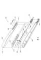
図1は、例示的なIOLインジェクタ装置100を例示する。いくつかの実施形態で、IOLインジェクタ装置100は、ハウジング102、カートリッジマウント104、1つ又は複数のボタン106、及びディスプレイ108を含む。ハウジング102は、任意の適当なサイズ、高さ、及び/又は形状とすることができる。無制限に、適当な形状が、円形、楕円形、三角形、長方形、正方形、六角形、及び/又はそれらの組み合わせの断面形状を含み得るが、これに限定されない。いくつかの実施形態で、ハウジング102は、円形の断面形状を有し、オペレータの手で把持するのに適した所定の長さ及び半径の円筒とすることができる。ハウジング102は、任意の適当な材料から作ることができる。適当な材料は、金属、非金属、ポリマー、セラミックス、及び/又はそれらの組み合わせを含み得るが、これに限定されない。いくつかの実施形態で、ハウジング102は、第1の部分116及び第2の部分118を有し得る。いくつかの実施形態で、第1の部分116及び第2の部分118は、縦方向に延びる境界面120に沿って接合し得る。例示された実施形態で、ハウジング102は、第1の端部110及び第2の端部112を有する。IOLインジェクタ装置100のオペレータが、第1の端部110の周りでIOLインジェクタ装置100を保持することができる。第2の端部112は、ハウジング102の(視界から遮られた)中央ボアへのアクセスを可能にする孔114を含み得る。いくつかの実施形態で、カートリッジマウント104は、ハウジング102の第2の端部112に配設することができる。 FIG. 1 illustrates an exemplary
カートリッジマウント104は、適当な留め具、ねじ切り、接着剤、スナップ式の方法、溶接、及び/又はそれらの任意の組み合わせの使用を通して、を含むがこれに限定されない、任意の適当な機構を使用することによって、ハウジング102の第2の端部112に配設することができる。無制限に、適当な留め具は、ナット及びボルト、ワッシャ、ねじ、ピン、ソケット、ロッド及びスタッド、蝶番、及び/又はそれらの任意の組み合わせを含み得る。例示された実施形態で、カートリッジマウント104は、ハウジング102からの延長である。場合によっては、カートリッジマウント104は、ハウジング102に一体的に接続され得る。他の場合には、カートリッジマウント104は、ハウジング102から独立していてもよく、連動関係を介してハウジング102に結合され得る。図1に描写されるように、カートリッジマウント104は、取り外し可能なように装着された挿入カートリッジ122を保持する。場合によっては、カートリッジマウント104は、挿入カートリッジ122を収容するための固有の切り抜き(例えばU字形)とし得る溝124を含む。代替の実施形態で、カートリッジマウント104は、任意の適当なサイズ、高さ、及び/又は形状とすることができる。いくつかの実施形態で、挿入カートリッジ122は、広げられたIOLを収容するように、且つプランジャチップ126がハウジング102から挿入カートリッジ122を通って前方に平行移動するときにIOLを折り畳んで移動させるように適合された使い捨てポリマー部材とすることができる。 The
1つ又は複数の1つ又は複数のボタン106a~106ca~106cは、ハウジング102上の任意の適当な場所に配設することができる。1つ又は複数のボタン106a~106cは、本明細書では、集合的に1つ又は複数のボタン106a~106cと呼び、個別に第1の1つ又は複数のボタン106a~106ca、第2の1つ又は複数のボタン106a~106cb、及び第3の1つ又は複数のボタン106a~106ccと呼ぶ。いくつかの実施形態で、1つ又は複数のボタン106は、図1に示されるように、第2の端部又はその近くに配設することができる。いくつかの実施形態で、ディスプレイ108に近接した1つ又は複数のボタン106a~106c。1つ又は複数のボタン106a~106cのうちの3つが図1に示されているが、特定用途のために希望に応じて、1つ又は複数のボタン106a~106cのうちの3つより多い又は少ないものがあってもよい。1つ又は複数のボタン106a~106cは、任意の適当なサイズ、高さ、及び/又は形状とすることができる。無制限に、適当な形状が、円形、楕円形、三角形、長方形、正方形、六角形、及び/又はそれらの組み合わせの断面形状を含み得るが、これに限定されない。いくつかの実施形態で、1つ又は複数のボタン106a~106cは、円形の断面形状を有してもよく、普通の「電源ボタン」に似ていてもよい。1つ又は複数のボタン106a~106cは、任意の適当な材料から作ることができる。適当な材料は、金属、非金属、ポリマー、セラミックス、及び/又はそれらの組み合わせを含み得るが、これに限定されない。 The one or
いくつかの実施形態で、1つ又は複数のボタン106a~106cは、1つ又は複数の異なるイベントをトリガするために使用され得る。例えば、第1のボタン106aは、オン/オフスイッチとすることができる。更なる例として、第2のボタン106bがプランジャチップ126を格納するようにトリガすることができる一方で、第3のボタン106cは、挿入プロセスを開始するようにトリガすることができる。いくつかの実施形態で、1つ又は複数のボタン106a~106cのそれぞれは、複数のイベントをトリガするためにトリガされ得る。いくつかの実施形態で、オペレータが、第1のボタンを押下することによってIOLインジェクタ装置100をオンにすることができる。次に、実施形態は、第3のボタン106cを押下することによってIOLインジェクタ装置100を作動させることを含み得る。いくつかの実施形態で、IOLインジェクタ装置100を作動させることは、挿入カートリッジ122からIOL(例えば、図5Aに示されるIOL408)を移動させるために、挿入カートリッジ122を通してプランジャチップ126を平行移動させることができる。いくつかの実施形態で、第2のボタン106bを押すと、プランジャチップ126の平行移動を停止させることができ、第2のボタン106bをさらにもう一度押すと、プランジャチップ126の格納が引き起こされる。加えて、図1は1つ又は複数のボタン106a~106cを例示するが、1つ又は複数のボタン106a~106cに加えて、又はそれらの代わりに、1つ若しくは複数のスイッチ又はタッチスクリーンディスプレイを含むがこれに限定されない、他の適当なユーザインタフェースがIOLインジェクタ装置100に組み込まれてもよいことを理解すべきである。 In some embodiments, one or
ディスプレイ108は、IOLインジェクタ装置100の状態についてオペレータに視覚情報を提示するための任意の適当な装置とすることができる。図1に示されるように、ディスプレイ108は、ハウジング102上に配置されたスクリーンの形態であってもよく、その上で文字列及び/又はテキストデータ型の指示がオペレータに表示され得る。任意の適当な指示がディスプレイ108によって示され得る。無制限に、例示的な指示は、「準備完了」、「エラー」、「格納」、「充電」、又は「休止」を含み得る。ディスプレイ108は、任意の適当なサイズ、高さ、及び/又は形状とすることができる。例示された実施形態で、ディスプレイ108は長方形である。図1は、ディスプレイ108を例示するが、可聴式状態指示器を提供するためのスピーカ又は視覚的若しくは色分けされた状態指示器を提供するためのライトを含むがこれに限定されない、他の適当なオペレータ指示器が、オペレータに情報を提供するために使用され得ることを理解すべきである。 The
図2は、図1の例示的なIOLインジェクタ装置100の分解組み立て図を例示する。ハウジング102の例示的な実施形態は、内部キャビティ200を含む。例示されるように、IOLインジェクタ装置100は、モータ202、ギアボックス204、作動ユニット206、プランジャ208、1つ又は複数のバッテリ210、及び回路基板212を含み、それらのそれぞれは、内部キャビティ200に配設されて示される。 FIG. 2 illustrates an exploded assembly diagram of the exemplary
モータ202は、1つ又は複数のバッテリ210からの電気エネルギーを機械的エネルギーに変換することが可能な任意の適当な電動モータとすることができる。いくつかの実施形態で、モータ202は、回転トルクを提供する。しかしながら、モータ202が1つ又は複数のバッテリ210からの電気エネルギーを直線運動に変換し得ることは、同様に考えられる。無制限に、モータ202は、直流(DC)ブラシレスモータ、DCブラシモータ、ステッパモータ、及び/又は誘導モータとすることができる。モータ202は、IOLインジェクタ装置100の内部キャビティ200内に配設されたままであるために任意の適当な寸法を有し得る。いくつかの実施形態で、モータ202は、ハウジング102の内部キャビティ200でIOLインジェクタ装置100の第1の端部110に配設することができる。 The
いくつかの実施形態で、ギアボックス204は、モータ202に結合される。例示されるように、ギアボックス204は、IOLインジェクタ装置100の第1の端部にあるモータ202に隣接して内部キャビティ200に配設される。ギアボックス204は、ギアハウジング214と、ギアハウジング214内に配設された任意の適当な数のギア(図示されない)とを含み得る(図2で最も良く見られる)。いくつかの実施形態で、ギアボックス204は、所定のギア比に従ってモータ202の角速度を減少させることができる。ギア比は、最初と最後のギアが回転する比率の間の任意の適当な比とすることができる。適当なギア比の実施例は、約125:1から約250:1に及ぶギア比を含み得るが、これに限定されない。いくつかの実施形態で、ギアボックス204の実装は、モータ202からの利用可能なトルクを増加させ、作動ユニット206が平行移動する速度を減少させることができる。 In some embodiments, the
いくつかの実施形態で、作動ユニット206は、モータ202からの回転運動を直線運動に変換することができる。例示された実施形態で、作動ユニット206は、ギアボックス204に隣接してハウジング102の内部キャビティ200内に配設され、作動ユニット206は、ギアボックス204に結合される。ギアボックス204は、作動ユニット206とモータ202との間に配設することができる。作動ユニット206は、任意の適当なサイズ、高さ、及び/又は形状とすることができる。いくつかの実施形態で、回転運動を直線運動に変換するために、任意の適当なリニアアクチュエータが作動ユニット206とともに使用され得る。無制限に、作動ユニット206は、親ねじアクチュエータ、ねじジャッキアクチュエータ、ボールねじアクチュエータ、及び/又はローラねじアクチュエータを含むがこれに限定されない、任意の適当なリニアアクチュエータを含み得る。いくつかの実施形態で、作動ユニット206は、外側ハウジング216を含む。例えば、外側ハウジング216は、リニアアクチュエータ(例示されない)が配設され得る中空の管状とすることができる。 In some embodiments, the
いくつかの実施形態で、プランジャ208は、作動ユニット206に結合される。例えば、プランジャは、外側ハウジング216内に配設されたリニアアクチュエータ(例示されない)に結合され得る。プランジャ208は、適当な留め具、ねじ切り、接着剤、スナップ式の方法、溶接、及び/又はそれらの任意の組み合わせの使用を含むがこれに限定されない、任意の適当な機構を使用することによって、作動ユニット206に取り付けることができる。適当な留め具の実施例は、ナット及びボルト、ワッシャ、ねじ、ピン、ソケット、ロッド及びスタッド、蝶番、及び/又はそれらの任意の組み合わせを含み得るが、これに限定されない。作動ユニット206が動作するとき、いくつかの実施形態で、プランジャ208は、直線的に移動する。作動ユニット206内に配設されたリニアアクチュエータが、モータ202によって提供される回転運動に起因して回転するとき、プランジャ208は、直線的に平行移動することができる。プランジャ208がハウジング102の内部キャビティ200を通って平行移動するとき、プランジャチップ126は、ハウジング102の第2の端部112を通って延びることができる。例えば、プランジャチップ126は、カートリッジマウント104上に配設された挿入カートリッジ122と係合するように第2の端部112の孔114を通って延びる。 In some embodiments, the plunger 208 is coupled to the
いくつかの実施形態で、IOLインジェクタ装置100は、IOLインジェクタ装置100のハウジング102内に配設された1つ又は複数のバッテリ210を含む。例えば、1つ又は複数のバッテリ210は、ハウジング102の内部キャビティ200で回路基板212上に配設される。いくつかの実施形態で、1つ又は複数のバッテリ210は、IOLインジェクタ装置100を動作させるために、モータ202に電力を供給する。本実施例では1つ又は複数のバッテリ210のうちの5つのみを示しているが、例示的な実施形態は、IOLインジェクタ装置100に電力を提供するのに適した任意の数のバッテリ210を網羅するように意図されることを理解すべきである。1つ又は複数のバッテリ210は、使い捨て及び/又は再充電可能とすることができる。1つ又は複数のバッテリ210は、アルカリ1.5Vバッテリを含むがこれに限定されない、任意の適当なタイプのバッテリを含み得る。いくつかの実施形態で、IOLインジェクタ装置100を動作させるために必要な最小電圧は、約7.5Vとすることができる。いくつかの実施形態で、1つ又は複数のバッテリ210は、任意の適当なサイズ、高さ、及び/又は形状とすることができる。無制限に、適当な形状が、円形、楕円形、三角形、長方形、正方形、六角形、及び/又はそれらの組み合わせの断面形状を含み得るが、これに限定されない。描写されるように、複数のバッテリ210は、断面が円形であってもよい。代替の実施形態で、各バッテリ210は、異なる形状であってもよい。 In some embodiments, the
回路基板212は、プリント回路基板を含むがこれに限定されない、任意の適当な回路基板とすることができる。いくつかの実施形態で、複数のバッテリ210は、任意の他の適当な電子部品(例えば、図4に示されるプロセッサ404)とともに回路基板212上にはんだ付けすることができる。いくつかの実施形態で、回路基板212は、IOLインジェクタ装置100のハウジング102の第1の端部110に配設されて、第2の端部112に向かって延びることができる。回路基板212は、モータ202、ギアボックス204、及び/又は作動ユニット206の一部分の長さに及び得る。いくつかの実施形態で、回路基板212及び/又は複数のバッテリ210は、モータ202、1つ又は複数のボタン106a~106c、ディスプレイ108、及び/又はそれらの組み合わせに配線されるか、又は別の方法でそれらと信号通信することができる。 The
図3Aは、充電ステーション300を持つIOLインジェクタ装置100の一実施形態を例示する。充電ステーション300は、1つ又は複数のバッテリ210が再充電可能である例示的な実施形態で1つ又は複数のバッテリ210(例えば、図2を参照すること)を充電するために利用され得る。いくつかの実施形態で、充電ステーション300は、任意の適当なサイズ、高さ、及び/又は形状とすることができる。無制限に、適当な形状が、円形、楕円形、三角形、長方形、正方形、六角形、及び/又はそれらの組み合わせの断面形状を含み得るが、これに限定されない。例示されていないが、いくつかの実施形態で、充電ステーション300は、フラットパッドの形態であってもよい。例示された実施形態で、充電ステーション300は、充電器本体302及び孔304を含む。孔304は、充電器本体302の第1の端部306に配設することができる。孔304は、IOLインジェクタ装置100の第1の端部110を受け入れるように構成され得る。充電器本体302の第2の端部308は、平坦にすることができ、その上で充電器本体302は、静止して置くことができる。電気ケーブル310が、充電器本体302に結合され得る。電気ケーブル310は、IOLインジェクタ装置100を再充電するための電源(図示されない)に充電器本体302を結合することができる。ここで図3Bを参照すると、いくつかの実施形態で、IOLインジェクタ装置100は、1つ又は複数のバッテリ210を充電するために孔304に挿入され得る。1つ又は複数のバッテリ210を十分に充電するには、任意の適当な量の時間がかかる場合がある。充電ステーション300が1つ又は複数のバッテリを再充電するために任意の適当な技法を使用し得ることを理解すべきである。例えば、充電ステーション300は、電磁誘導充電、無線充電、又は共振充電などのワイヤレス充電技法を使用し得る。 FIG. 3A illustrates an embodiment of an
図4は、患者400の治療のためのIOLインジェクタ装置100のある特定の構成要素を例示するブロック図である。例示されるように、例示的なIOLインジェクタ装置100は、1つ又は複数のバッテリ210、ユーザインタフェース402、プロセッサ404、及び作動システム406を含む。いくつかの実施形態で、1つ又は複数のバッテリ210は、ユーザインタフェース402、プロセッサ404、及び/又は作動システム406を含むがこれに限定されない、IOLインジェクタ装置100の他の構成要素に給電することができる。例えば、1つ又は複数のバッテリ210は、作動システム406のモータ202に電力を提供する。例示された実施形態で、ユーザインタフェース402は、1つ又は複数のボタン106~106c及びディスプレイ108を含む。いくつかの実施形態で、1つ又は複数のバッテリ210が再充電可能である場合に、例えば、使用に先立って1つ又は複数のバッテリ210を充電するために、充電ステーション300が使用され得る。ユーザインタフェース402は、例えば、1つ又は複数のボタン106a~106cを通して、オペレータから入力を受け取ることができ、例えば、ディスプレイ108を通して、オペレータに情報を提供することができる。プロセッサ404は、例えば、IOLインジェクタ装置100の動作を開始及び/又は停止するために、ユーザインタフェース402を通してオペレータから入力を受け取るように構成され得る。いくつかの実施形態で、プロセッサ404は、回路基板212(例えば、図2に示される)上に配設することができる。プロセッサ404は、マイクロプロセッサ、マイクロコントローラ、組み込みマイクロコントローラ、プログラマブルデジタル信号プロセッサ、又は他のプログラマブルデバイスを含むがこれに限定されない、命令を処理するための任意の適当なデバイスを含み得る。プロセッサ404は、同様に、又は代わりに、特定用途向け集積回路、プログラマブル・ゲート・アレイ、プログラマブル・アレイ・ロジック、又は電気信号を処理するように動作可能なデバイスの組み合わせの任意の他のデバイスで実施され得る。プロセッサ404は、ユーザインタフェース402及び作動システム406に、通信可能に結合され得る。いくつかの実施形態で、作動システム406は、モータ202、ギアボックス204、作動ユニット206、及びプランジャ208を含む。作動システム406は、プロセッサ404からコマンドを受け取るように構成され得る。例えば、プロセッサ404は、モータ202に動作するように命令することができる。作動ユニット206は、モータ202からの回転運動を直線運動に変換することができる。作動ユニット206がプランジャ208を移動させるとき、プランジャチップ126(例えば、図1に示される)は、挿入カートリッジ122と係合し得る。例えば、プランジャ208は、挿入カートリッジ122内に配設されたIOL408を押して、挿入カートリッジ122を通して及び/又は挿入カートリッジ122から患者400の眼(例えば、図5Aに示される眼500)の中にIOL408を移動させることができる。IOL408は、眼の天然の水晶体の形状に類似した形状を有し得る。IOL408は、シリコーン、アクリル、及び/又はそれらの組み合わせを含むがこれに限定されない、非常に多くの材料から作ることができる。他の適当な材料が同様に考えられる。 FIG. 4 is a block diagram illustrating certain components of the
図5Aは、IOLインジェクタ装置100を用いた手術を受けている患者の眼500を例示する。例示されるように、IOLインジェクタ装置100は、IOL408を患者の眼500に施す。いくつかの実施形態で、IOL408は、折り畳まれた状態であってもよい。いくつかの実施形態で、外科医によって眼500に切開部502が作られる。例えば、場合によっては、切開部502は、眼500の強膜504を通して作ることができる。他の場合には、切開部502は、眼500の角膜506に形成することができる。切開部502のサイズは、水晶体嚢508にIOL408を送り込むためにIOLインジェクタ装置100の一部分の挿入を可能にするように定めることができる。例えば、場合によっては、切開部502のサイズは、約2000ミクロン(2ミリメートル)未満の長さを有し得る。他の場合には、切開部502は、約0ミクロン~約500ミクロン、約500ミクロン~約1000ミクロン、約1000ミクロン~約1500ミクロン、又は約1500ミクロン~約2000ミクロンの長さを有し得る。 FIG. 5A illustrates an
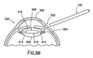
切開部502が作られた後、IOLインジェクタ装置100は、切開部502を通して眼500の内部510に挿入される。IOLインジェクタ装置100は、IOL408を眼500の水晶体嚢508に施すように作動される。施されると、IOL408は、初期の広がった状態に戻ることができ、IOL408は、図5Bに示されるように、眼500の水晶体嚢508内に収まる。水晶体嚢508は、IOL408の光学部品512が網膜(図示されない)に向けられた光を屈折させるように、眼500との相対関係で眼500内にIOL408を保持する。IOL408は、光学部品512から延び、水晶体嚢508と係合してそこにIOL408を固定する触覚部514を含む。IOL408を水晶体嚢508に施した後、IOLインジェクタ装置100は、切開部502を通して眼500から除去され、眼500は、時間とともに治癒することが可能になる。 After the
本開示の動作及び構造は、前述の説明から明らかになると思われる。上に示され又は説明された装置及び方法は、好ましいものとして特徴付けられてきたが、以下の特許請求の範囲に定められる本開示の精神及び適用範囲から逸脱することなく、さまざまな変更及び修正がその中でなされ得る。 The operation and structure of the present disclosure will be apparent from the above description. The devices and methods shown or described above have been characterized as preferred, but without departing from the spirit and scope of the present disclosure set forth in the claims below, various changes and modifications. Can be done in it.
Claims (15)
Translated fromJapaneseバッテリと、
前記ハウジング内に配設されたプランジャと、
前記バッテリによって給電され、前記プランジャを前記ハウジング中で平行移動させるように構成された、モータと、
前記ハウジング上に配設されたユーザインタフェースであって、前記プランジャの平行移動を開始するためのユーザ入力を受け取る、ユーザインタフェースと、
を備える、眼内レンズインジェクタ装置。A housing comprising a first end and a second end.
With the battery
The plunger disposed in the housing and
A motor powered by the battery and configured to translate the plunger in the housing.
A user interface disposed on the housing that receives user input for initiating translation of the plunger.
Intraocular lens injector device.
Applications Claiming Priority (3)
| Application Number | Priority Date | Filing Date | Title |
|---|---|---|---|
| US201862777797P | 2018-12-11 | 2018-12-11 | |
| US62/777,797 | 2018-12-11 | ||
| PCT/IB2019/060522WO2020121143A1 (en) | 2018-12-11 | 2019-12-06 | Battery-powered intraocular lens injector |
Publications (2)
| Publication Number | Publication Date |
|---|---|
| JP2022510881Atrue JP2022510881A (en) | 2022-01-28 |
| JP7438215B2 JP7438215B2 (en) | 2024-02-26 |
Family
ID=68887085
Family Applications (1)
| Application Number | Title | Priority Date | Filing Date |
|---|---|---|---|
| JP2021529489AActiveJP7438215B2 (en) | 2018-12-11 | 2019-12-06 | Battery-powered intraocular lens injector |
Country Status (8)
| Country | Link |
|---|---|
| US (1) | US20200179102A1 (en) |
| EP (1) | EP3860508B1 (en) |
| JP (1) | JP7438215B2 (en) |
| CN (1) | CN113164250A (en) |
| AU (1) | AU2019398796B2 (en) |
| CA (1) | CA3118649A1 (en) |
| ES (1) | ES2993233T3 (en) |
| WO (1) | WO2020121143A1 (en) |
Families Citing this family (7)
| Publication number | Priority date | Publication date | Assignee | Title |
|---|---|---|---|---|
| WO2020240418A1 (en) | 2019-05-29 | 2020-12-03 | Alcon Inc. | Vitrectomy probe interfacing component |
| WO2021245556A1 (en) | 2020-06-02 | 2021-12-09 | Alcon Inc. | Hydraulic delivery of surgical implants |
| US11839537B2 (en) | 2020-11-12 | 2023-12-12 | Alcon Inc. | Hydraulic delivery of surgical implants |
| CN116528797A (en) | 2020-12-03 | 2023-08-01 | 爱尔康公司 | Loop handling for delivery of intraocular implants |
| US12403002B2 (en) | 2020-12-22 | 2025-09-02 | Alcon Inc. | Hybrid power delivery for surgical implants |
| CA3203511A1 (en) | 2021-01-15 | 2022-07-21 | Austin Xavier Rodeheaver | Magnetically coupled power delivery for surgical implants |
| US11911262B2 (en) | 2021-01-29 | 2024-02-27 | Alcon Inc. | Ratchet drive delivery for surgical implants |
Citations (3)
| Publication number | Priority date | Publication date | Assignee | Title |
|---|---|---|---|---|
| US20050020909A1 (en)* | 2003-07-10 | 2005-01-27 | Moctezuma De La Barrera Jose Luis | Display device for surgery and method for using the same |
| US20120116380A1 (en)* | 2010-11-05 | 2012-05-10 | Madan Ashvani K | Sterile Medical Instrument Charging Device |
| US20130197532A1 (en)* | 2012-01-27 | 2013-08-01 | Mikhail Boukhny | Automated intraocular lens injector device |
Family Cites Families (6)
| Publication number | Priority date | Publication date | Assignee | Title |
|---|---|---|---|---|
| US4836201A (en)* | 1988-03-24 | 1989-06-06 | Patton Medical Technologies, Inc. | "Envelope" apparatus for inserting intra-ocular lens into the eye |
| US9681947B2 (en)* | 2006-10-23 | 2017-06-20 | Novartis Ag | Intraocular lens delivery system with temperature control |
| US9125737B2 (en)* | 2008-12-18 | 2015-09-08 | Alcon Research, Ltd. | Constant force intraocular lens injector |
| US9480555B2 (en)* | 2013-04-03 | 2016-11-01 | Novartis Ag | Automated intraocular lens injector device |
| US10188507B2 (en)* | 2015-07-31 | 2019-01-29 | Nidek Co., Ltd. | Intraocular lens injection system and controller for controlling intraocular lens injection device |
| EP3319553B1 (en)* | 2015-08-14 | 2024-01-31 | Willis, Timothy R. | Intraocular lenses (iols) and related assemblies |
- 2019
- 2019-12-06CNCN201980081417.6Apatent/CN113164250A/enactivePending
- 2019-12-06ESES19820880Tpatent/ES2993233T3/enactiveActive
- 2019-12-06AUAU2019398796Apatent/AU2019398796B2/enactiveActive
- 2019-12-06JPJP2021529489Apatent/JP7438215B2/enactiveActive
- 2019-12-06USUS16/705,309patent/US20200179102A1/ennot_activeAbandoned
- 2019-12-06CACA3118649Apatent/CA3118649A1/enactivePending
- 2019-12-06EPEP19820880.3Apatent/EP3860508B1/enactiveActive
- 2019-12-06WOPCT/IB2019/060522patent/WO2020121143A1/ennot_activeCeased
Patent Citations (3)
| Publication number | Priority date | Publication date | Assignee | Title |
|---|---|---|---|---|
| US20050020909A1 (en)* | 2003-07-10 | 2005-01-27 | Moctezuma De La Barrera Jose Luis | Display device for surgery and method for using the same |
| US20120116380A1 (en)* | 2010-11-05 | 2012-05-10 | Madan Ashvani K | Sterile Medical Instrument Charging Device |
| US20130197532A1 (en)* | 2012-01-27 | 2013-08-01 | Mikhail Boukhny | Automated intraocular lens injector device |
Also Published As
| Publication number | Publication date |
|---|---|
| US20200179102A1 (en) | 2020-06-11 |
| CN113164250A (en) | 2021-07-23 |
| AU2019398796B2 (en) | 2025-06-26 |
| ES2993233T3 (en) | 2024-12-26 |
| EP3860508B1 (en) | 2024-07-31 |
| EP3860508A1 (en) | 2021-08-11 |
| JP7438215B2 (en) | 2024-02-26 |
| WO2020121143A1 (en) | 2020-06-18 |
| AU2019398796A1 (en) | 2021-05-27 |
| CA3118649A1 (en) | 2020-06-18 |
Similar Documents
| Publication | Publication Date | Title |
|---|---|---|
| JP7438215B2 (en) | Battery-powered intraocular lens injector | |
| JP5719022B2 (en) | Ophthalmic surgical device for reaching tissue and performing capsulotomy | |
| US9681947B2 (en) | Intraocular lens delivery system with temperature control | |
| EP2086468B1 (en) | Method of preparing an intraocular lens delivery device | |
| EP1832259B1 (en) | Pulse amplitude manipulation for controlling a phacoemulsification surgical system | |
| JP7439081B2 (en) | Haptic-optic management system using a rotating arm | |
| US20140142560A1 (en) | Ophthalmic surgical device for capsulotomy | |
| CN102271606A (en) | Flexible, automated capsulorhexis device | |
| EP2560577B1 (en) | Intraocular lens temperature control system | |
| MX2007005846A (en) | Drug delivery device. | |
| JP2003319964A (en) | Surgical cassette latching mechanism | |
| AU2011242540A1 (en) | Insertion mode phacoemulsification employing powered IOL delivery | |
| JP6019064B2 (en) | Ophthalmic surgical device for reaching tissue and performing capsulotomy | |
| CN214805706U (en) | Intraocular implant implantation device | |
| EP4284301A1 (en) | Ratchet drive delivery for surgical implants | |
| CN116615155A (en) | Hybrid power delivery of surgical implants | |
| RU2806334C2 (en) | Optical-haptic control system using rotary cams | |
| BR112021011137B1 (en) | OPTICAL HAPTIC MANAGEMENT SYSTEM, INSERTION TOOL, AND DELIVERY METHOD FOR AN INTRAOCULAR LENS | |
| JP2014100418A (en) | Switch device |
Legal Events
| Date | Code | Title | Description |
|---|---|---|---|
| A621 | Written request for application examination | Free format text:JAPANESE INTERMEDIATE CODE: A621 Effective date:20221125 | |
| A131 | Notification of reasons for refusal | Free format text:JAPANESE INTERMEDIATE CODE: A131 Effective date:20230808 | |
| A521 | Request for written amendment filed | Free format text:JAPANESE INTERMEDIATE CODE: A523 Effective date:20231108 | |
| TRDD | Decision of grant or rejection written | ||
| A01 | Written decision to grant a patent or to grant a registration (utility model) | Free format text:JAPANESE INTERMEDIATE CODE: A01 Effective date:20240123 | |
| A61 | First payment of annual fees (during grant procedure) | Free format text:JAPANESE INTERMEDIATE CODE: A61 Effective date:20240213 | |
| R150 | Certificate of patent or registration of utility model | Ref document number:7438215 Country of ref document:JP Free format text:JAPANESE INTERMEDIATE CODE: R150 |