JP2022509771A - Devices, systems, and methods for local dimming in a brightness controlled environment - Google Patents
Devices, systems, and methods for local dimming in a brightness controlled environmentDownload PDFInfo
- Publication number
- JP2022509771A JP2022509771AJP2021526579AJP2021526579AJP2022509771AJP 2022509771 AJP2022509771 AJP 2022509771AJP 2021526579 AJP2021526579 AJP 2021526579AJP 2021526579 AJP2021526579 AJP 2021526579AJP 2022509771 AJP2022509771 AJP 2022509771A
- Authority
- JP
- Japan
- Prior art keywords
- image
- luminance level
- level
- absolute
- relative
- Prior art date
- Legal status (The legal status is an assumption and is not a legal conclusion. Google has not performed a legal analysis and makes no representation as to the accuracy of the status listed.)
- Pending
Links
Images


Classifications
- G—PHYSICS
- G09—EDUCATION; CRYPTOGRAPHY; DISPLAY; ADVERTISING; SEALS
- G09G—ARRANGEMENTS OR CIRCUITS FOR CONTROL OF INDICATING DEVICES USING STATIC MEANS TO PRESENT VARIABLE INFORMATION
- G09G5/00—Control arrangements or circuits for visual indicators common to cathode-ray tube indicators and other visual indicators
- G09G5/10—Intensity circuits
- G—PHYSICS
- G09—EDUCATION; CRYPTOGRAPHY; DISPLAY; ADVERTISING; SEALS
- G09G—ARRANGEMENTS OR CIRCUITS FOR CONTROL OF INDICATING DEVICES USING STATIC MEANS TO PRESENT VARIABLE INFORMATION
- G09G3/00—Control arrangements or circuits, of interest only in connection with visual indicators other than cathode-ray tubes
- G09G3/20—Control arrangements or circuits, of interest only in connection with visual indicators other than cathode-ray tubes for presentation of an assembly of a number of characters, e.g. a page, by composing the assembly by combination of individual elements arranged in a matrix no fixed position being assigned to or needed to be assigned to the individual characters or partial characters
- G09G3/34—Control arrangements or circuits, of interest only in connection with visual indicators other than cathode-ray tubes for presentation of an assembly of a number of characters, e.g. a page, by composing the assembly by combination of individual elements arranged in a matrix no fixed position being assigned to or needed to be assigned to the individual characters or partial characters by control of light from an independent source
- G09G3/3406—Control of illumination source
- G09G3/342—Control of illumination source using several illumination sources separately controlled corresponding to different display panel areas, e.g. along one dimension such as lines
- G09G3/3426—Control of illumination source using several illumination sources separately controlled corresponding to different display panel areas, e.g. along one dimension such as lines the different display panel areas being distributed in two dimensions, e.g. matrix
- G—PHYSICS
- G06—COMPUTING OR CALCULATING; COUNTING
- G06F—ELECTRIC DIGITAL DATA PROCESSING
- G06F3/00—Input arrangements for transferring data to be processed into a form capable of being handled by the computer; Output arrangements for transferring data from processing unit to output unit, e.g. interface arrangements
- G06F3/14—Digital output to display device ; Cooperation and interconnection of the display device with other functional units
- G06F3/147—Digital output to display device ; Cooperation and interconnection of the display device with other functional units using display panels
- G—PHYSICS
- G09—EDUCATION; CRYPTOGRAPHY; DISPLAY; ADVERTISING; SEALS
- G09G—ARRANGEMENTS OR CIRCUITS FOR CONTROL OF INDICATING DEVICES USING STATIC MEANS TO PRESENT VARIABLE INFORMATION
- G09G3/00—Control arrangements or circuits, of interest only in connection with visual indicators other than cathode-ray tubes
- G09G3/001—Control arrangements or circuits, of interest only in connection with visual indicators other than cathode-ray tubes using specific devices not provided for in groups G09G3/02 - G09G3/36, e.g. using an intermediate record carrier such as a film slide; Projection systems; Display of non-alphanumerical information, solely or in combination with alphanumerical information, e.g. digital display on projected diapositive as background
- G09G3/003—Control arrangements or circuits, of interest only in connection with visual indicators other than cathode-ray tubes using specific devices not provided for in groups G09G3/02 - G09G3/36, e.g. using an intermediate record carrier such as a film slide; Projection systems; Display of non-alphanumerical information, solely or in combination with alphanumerical information, e.g. digital display on projected diapositive as background to produce spatial visual effects
- G—PHYSICS
- G09—EDUCATION; CRYPTOGRAPHY; DISPLAY; ADVERTISING; SEALS
- G09G—ARRANGEMENTS OR CIRCUITS FOR CONTROL OF INDICATING DEVICES USING STATIC MEANS TO PRESENT VARIABLE INFORMATION
- G09G2320/00—Control of display operating conditions
- G09G2320/02—Improving the quality of display appearance
- G09G2320/0261—Improving the quality of display appearance in the context of movement of objects on the screen or movement of the observer relative to the screen
- G—PHYSICS
- G09—EDUCATION; CRYPTOGRAPHY; DISPLAY; ADVERTISING; SEALS
- G09G—ARRANGEMENTS OR CIRCUITS FOR CONTROL OF INDICATING DEVICES USING STATIC MEANS TO PRESENT VARIABLE INFORMATION
- G09G2320/00—Control of display operating conditions
- G09G2320/06—Adjustment of display parameters
- G09G2320/0626—Adjustment of display parameters for control of overall brightness
- G09G2320/0646—Modulation of illumination source brightness and image signal correlated to each other
- G—PHYSICS
- G09—EDUCATION; CRYPTOGRAPHY; DISPLAY; ADVERTISING; SEALS
- G09G—ARRANGEMENTS OR CIRCUITS FOR CONTROL OF INDICATING DEVICES USING STATIC MEANS TO PRESENT VARIABLE INFORMATION
- G09G2320/00—Control of display operating conditions
- G09G2320/06—Adjustment of display parameters
- G09G2320/0686—Adjustment of display parameters with two or more screen areas displaying information with different brightness or colours
- G—PHYSICS
- G09—EDUCATION; CRYPTOGRAPHY; DISPLAY; ADVERTISING; SEALS
- G09G—ARRANGEMENTS OR CIRCUITS FOR CONTROL OF INDICATING DEVICES USING STATIC MEANS TO PRESENT VARIABLE INFORMATION
- G09G2320/00—Control of display operating conditions
- G09G2320/10—Special adaptations of display systems for operation with variable images
- G—PHYSICS
- G09—EDUCATION; CRYPTOGRAPHY; DISPLAY; ADVERTISING; SEALS
- G09G—ARRANGEMENTS OR CIRCUITS FOR CONTROL OF INDICATING DEVICES USING STATIC MEANS TO PRESENT VARIABLE INFORMATION
- G09G2340/00—Aspects of display data processing
- G09G2340/16—Determination of a pixel data signal depending on the signal applied in the previous frame
- G—PHYSICS
- G09—EDUCATION; CRYPTOGRAPHY; DISPLAY; ADVERTISING; SEALS
- G09G—ARRANGEMENTS OR CIRCUITS FOR CONTROL OF INDICATING DEVICES USING STATIC MEANS TO PRESENT VARIABLE INFORMATION
- G09G2354/00—Aspects of interface with display user
- G—PHYSICS
- G09—EDUCATION; CRYPTOGRAPHY; DISPLAY; ADVERTISING; SEALS
- G09G—ARRANGEMENTS OR CIRCUITS FOR CONTROL OF INDICATING DEVICES USING STATIC MEANS TO PRESENT VARIABLE INFORMATION
- G09G2360/00—Aspects of the architecture of display systems
- G09G2360/16—Calculation or use of calculated indices related to luminance levels in display data
Landscapes
- Engineering & Computer Science (AREA)
- Theoretical Computer Science (AREA)
- Physics & Mathematics (AREA)
- General Physics & Mathematics (AREA)
- Computer Hardware Design (AREA)
- Human Computer Interaction (AREA)
- General Engineering & Computer Science (AREA)
- Liquid Crystal Display Device Control (AREA)
- Control Of Indicators Other Than Cathode Ray Tubes (AREA)
- Liquid Crystal (AREA)
Abstract
Translated fromJapaneseDescription
Translated fromJapanese仮想現実(VR)および拡張現実(AR)ヘッドセットは、ますます多くの活動において使用するのに人気が高まっている。そのようなヘッドセットは、ユーザの視野に視覚情報を組み込んで、ユーザの周囲を増強するかまたはユーザが没入型3次元環境に入ることを可能にし得る。仮想現実および拡張現実ヘッドセットは、しばしばゲーミングおよび他のエンターテインメント目的で利用されるが、それらのヘッドセットはレクリエーション以外の目的でも一般に採用され、たとえば、政府は、軍事訓練シミュレーションのためにヘッドセットを使用することがあり、医師は、手術を実践するためにヘッドセットを使用することがあり、技術者は、可視化補助としてヘッドセットを使用することがある。仮想および拡張現実システムはまた、様々なコンテキストにおける個人間の対人的相互作用を促進する際のそれらのシステムの効用がますます認識されている。 Virtual reality (VR) and augmented reality (AR) headsets are becoming more and more popular for use in more and more activities. Such headsets may incorporate visual information into the user's field of view to enhance the user's surroundings or allow the user to enter an immersive 3D environment. Virtual reality and augmented reality headsets are often used for gaming and other entertainment purposes, but they are also commonly adopted for purposes other than recreation, for example, governments use headsets for military training simulations. May be used, doctors may use headsets to practice surgery, and technicians may use headsets as a visualization aid. Virtual and augmented reality systems are also increasingly recognized for their utility in facilitating interpersonal interactions between individuals in various contexts.
多くの仮想および拡張現実ヘッドセットのコンパクトなサイズにより、そのようなヘッドセットにおいて利用されるディスプレイスクリーンは、高品質、高解像度の画像を表示しながらも、小さいプロファイルを有する必要があり得る。着用者の眼は、ヘッドセットのレンズによってさらに拡大され得るディスプレイスクリーンに比較的近接して位置し得るので、表示される画像中のどんな不整合も、他のタイプのディスプレイデバイスにおけるそのような不整合よりも、ヘッドセットユーザに容易に明らかであり得る。残念ながら、より比較的低いコストおよび高い可用性により、ヘッドセットに時々組み込まれる典型的な液晶ディスプレイ(LCD)は、いくつかの望ましくないディスプレイアーティファクトを呈することがある。たとえば、従来の液晶(LC)パネルは、光漏れまたは「光ブリード」をしばしば起こしやすく、それによって劣悪なコントラスト比および劣悪な黒レベルが生じ得る。いくつかのLCD(たとえば、LCDテレビジョンなどの大型ファクタLCD)は、特に高コントラスト画像を表示するとき、コントラスト比および黒レベルを向上させるために局所的に減光可能なバックライトアレイを採用することがある。残念ながら、局所減光が可能なバックライトを使用する従来のLCDは、典型的には、特により暗い背景上の明るいオブジェクトの周りでは、ハローイングアーティファクトを呈する。その上、局所減光が可能な従来のバックライトは、典型的には、それらのバックライトが照明するLCパネルよりも遅いリフレッシュレートを有し、それにより、ディスプレイアーティファクトに伴う問題が悪化し得る。たとえば、局所減光が可能なバックライトを使用する従来のLCDを介して表示されたとき、迅速に動いているオブジェクトは、それらのオブジェクトの通過後にゴースト痕跡を残すことがある。その結果、従来のLCDヘッドセットを用いたユーザのエクスペリエンスは、準最適になり得る。 Due to the compact size of many virtual and augmented reality headsets, the display screens utilized in such headsets may need to have a small profile while displaying high quality, high resolution images. Since the wearer's eyes can be located relatively close to the display screen, which can be further magnified by the headset lens, any inconsistencies in the displayed image are such inconsistencies in other types of display devices. It can be more easily obvious to the headset user than matching. Unfortunately, due to its relatively lower cost and higher availability, typical liquid crystal displays (LCDs) that are sometimes incorporated into headsets can exhibit some unwanted display artifacts. For example, conventional liquid crystal (LC) panels are often prone to light leakage or "light bleeding", which can result in poor contrast ratios and poor black levels. Some LCDs (eg, large factor LCDs such as LCD televisions) employ locally dimmable backlight arrays to improve contrast ratio and black level, especially when displaying high contrast images. Sometimes. Unfortunately, traditional LCDs that use locally dimmable backlights typically exhibit haloing artifacts, especially around bright objects on darker backgrounds. Moreover, traditional backlights capable of local dimming typically have a slower refresh rate than the LC panels they illuminate, which can exacerbate the problems associated with display artifacts. .. For example, fast-moving objects may leave ghost traces after passing through them, for example, when viewed through a traditional LCD with a locally dimmable backlight. As a result, the user experience with traditional LCD headsets can be suboptimal.
以下でより詳細に説明されるように、本開示では、輝度制御された環境(たとえば、ユーザが外部輝度レベルを参照するのを実質的に防止されたVRヘッドセット)においてバックライトの局所減光を実施するための様々な装置、システム、および方法について説明する。いくつかの例では、コンピュータ実装方法は、(1)画像ブロックを含む画像を受信することであって、画像が、ディスプレイパネルを介して表示されるべきである、画像を受信することと、(2)画像ブロックの各々の絶対輝度レベルを決定することと、(3)画像ブロックの各々について、内部参照輝度レベルに基づいて相対輝度レベルを導出することと、(4)ディスプレイパネルのバックライトアレイの各発光要素について、画像ブロックの対応する部分の相対輝度レベルに基づいて照明レベルを計算することと、(5)画像がディスプレイパネルを介して表示されている間、発光要素について計算された照明レベルに従ってバックライトアレイの発光要素の各々を照明させることと、を含み得る。いくつかの例では、ディスプレイパネルは、複数のピクセル領域を含み得、バックライトアレイは、ピクセル領域の後ろでディスプレイパネルに結合され得、ピクセル領域の対応する部分を照明するように各々構成された発光要素を含み得、ディスプレイパネルおよびバックライトアレイは、閲覧者が外部輝度レベルを参照するのを実質的に防止するように構成され得る。 As described in more detail below, the present disclosure presents local dimming of the backlight in a brightness controlled environment (eg, a VR headset that substantially prevents the user from referencing an external brightness level). Describes various devices, systems, and methods for carrying out. In some examples, the computer implementation method is (1) to receive an image containing an image block, and the image should be displayed via a display panel, receiving the image, and ( 2) Determining the absolute luminance level of each of the image blocks, (3) Deriving the relative luminance level of each of the image blocks based on the internal reference luminance level, and (4) Backlit array of display panels. For each light emitting element of, the illumination level is calculated based on the relative brightness level of the corresponding portion of the image block, and (5) the illumination calculated for the light emitting element while the image is displayed through the display panel. It may include illuminating each of the light emitting elements of the backlight array according to the level. In some examples, the display panel may contain multiple pixel areas, and the backlight array may be coupled to the display panel behind the pixel areas, each configured to illuminate the corresponding portion of the pixel area. A light emitting element may be included and the display panel and backlight array may be configured to substantially prevent the viewer from referencing an external brightness level.
いくつかの例では、少なくとも1つの内部参照輝度レベルは、画像ブロックのうちの別の1つの絶対輝度レベルまたは相対輝度レベルを含み得る。 In some examples, at least one internal reference luminance level may include another absolute luminance level or relative luminance level of the image block.
一例では、画像ブロックの各々について相対輝度レベルを導出するステップは、(1)より低い絶対輝度レベルを有する画像ブロックのうちの1つまたは複数を含む画像の第1の画像領域を識別することと、(2)より高い絶対輝度レベルを有する画像ブロックのうちの1つまたは複数を含む画像の第2の画像領域を識別することと、(3)より低い絶対輝度レベルとより高い絶対輝度レベルとの間の差を計算することと、(4)第1の領域中の画像ブロックの各々について、より低い絶対輝度レベルよりも低い第1の相対輝度レベルを導出することと、(5)第2の領域中の画像ブロックの各々について、第1の相対輝度レベルと差との和に実質的に等しい第2の相対輝度レベルを導出することと、を含み得る。 In one example, the step of deriving the relative brightness level for each of the image blocks is to identify a first image area of the image containing one or more of the image blocks having an absolute brightness level lower than (1). , (2) Identifying a second image area of an image containing one or more of the image blocks having a higher absolute brightness level, and (3) lower and higher absolute brightness levels. Calculating the difference between, (4) deriving a first relative brightness level lower than the lower absolute brightness level for each of the image blocks in the first region, and (5) second. For each of the image blocks in the region, it may include deriving a second relative brightness level that is substantially equal to the sum of the first relative brightness level and the difference.
追加または代替として、画像ブロックの各々について相対輝度レベルを導出するステップは、(1)より低い絶対輝度レベルを有する画像の第1の画像領域を識別することと、(2)実質的に同様のより高い絶対輝度レベルを有する画像ブロックのうちの2つ以上を含む画像の第2の画像領域を識別することと、(3)第2の画像領域について、閲覧者によって知覚されたとき、単一の輝度レベルとして実質的に見える輝度レベル勾配を導出することと、(4)第1の画像領域から最も遠い第2の画像領域内の画像ブロックが、最も高い輝度レベルを有し、第1の画像領域に最も近い第2の画像領域内の画像ブロックが、最も低い輝度レベルを有するように、輝度レベル勾配からの輝度レベルを画像ブロックのうちの2つ以上に割り当てることと、を含み得る。 As an addition or alternative, the step of deriving the relative luminance level for each of the image blocks is (2) substantially similar to (2) identifying a first image region of an image having an absolute luminance level lower than (1). Identifying a second image area of an image containing two or more of image blocks with higher absolute brightness levels, and (3) a single when perceived by the viewer for the second image area. Deriving a luminance level gradient that is substantially visible as the luminance level of It may include assigning a luminance level from a luminance level gradient to two or more of the image blocks such that the image block in the second image region closest to the image region has the lowest luminance level.
追加または代替として、画像ブロックの各々について相対輝度レベルを導出するステップは、(1)より高い絶対輝度レベルを有する画像の第1の画像領域を識別することと、(2)実質的に同様のより低い絶対輝度レベルを有する画像ブロックのうちの2つ以上を含む画像の第2の画像領域を識別することと、(3)第2の画像領域について、閲覧者によって知覚されたとき、単一の輝度レベルとして実質的に見える輝度レベル勾配を導出することと、(4)第1の画像領域から最も遠い第2の画像領域内の画像ブロックが、最も低い輝度レベルを有し、第1の画像領域に最も近い第2の画像領域内の画像ブロックが、最も高い輝度レベルを有するように、輝度レベル勾配からの輝度レベルを画像ブロックのうちの2つ以上に割り当てることと、を含み得る。 As an addition or alternative, the step of deriving the relative luminance level for each of the image blocks is (1) substantially similar to (2) identifying a first image region of an image having an absolute luminance level higher than. Identifying a second image area of an image containing two or more of image blocks with lower absolute luminance levels, and (3) a single when perceived by the viewer for the second image area. Derivation of a luminance level gradient that is substantially visible as the luminance level of (4) the image block in the second image region farthest from the first image region has the lowest luminance level and the first It may include assigning a luminance level from a luminance level gradient to two or more of the image blocks such that the image block in the second image region closest to the image region has the highest luminance level.
いくつかの例では、少なくとも1つの内部参照輝度レベルは、ディスプレイパネルを介して既に表示された追加の画像の画像ブロックの絶対輝度レベルまたは相対輝度レベルを含み得る。いくつかの例では、画像ブロックの各々について相対輝度レベルを導出するステップは、(1)第1の絶対輝度レベルを有する画像の画像ブロックを識別することと、(2)第1の絶対輝度レベルに実質的に等しい第2の絶対輝度レベルを有する追加の画像の画像ブロックを識別することと、(3)追加の画像の画像ブロックの相対輝度レベルを決定することと、(4)追加の画像の画像ブロックの相対輝度レベルと画像の画像ブロックの相対輝度レベルとの間の差が、閲覧者にとって実質的に知覚できないように、追加の画像の画像ブロックの相対輝度レベルよりも低い画像の画像ブロックの相対輝度レベルを導出することと、を含み得る。いくつかの例では、ディスプレイパネルおよびバックライトアレイは、ヘッドマウントディスプレイデバイスの一部分を形成し得、ヘッドマウントディスプレイデバイスは、ディスプレイパネルおよびバックライトアレイを囲んでおり、閲覧者が外部輝度レベルを参照するのを実質的に防止するように構成されたディスプレイハウジングを含み得る。 In some examples, the at least one internal reference luminance level may include an absolute luminance level or a relative luminance level of an image block of additional images already displayed via the display panel. In some examples, the steps to derive the relative brightness level for each of the image blocks are (1) identifying the image block of the image with the first absolute brightness level and (2) the first absolute brightness level. Identifying additional image blocks with a second absolute brightness level that is substantially equal to, (3) determining the relative brightness levels of the image blocks of the additional image, and (4) additional images. Images of images that are lower than the relative brightness levels of the image blocks of additional images so that the difference between the relative brightness levels of the image blocks of the image and the relative brightness levels of the image blocks of the image is virtually imperceptible to the viewer. It may include deriving the relative brightness level of the block. In some examples, the display panel and backlight array may form part of a head-mounted display device, which surrounds the display panel and backlight array so that the viewer can see the external brightness level. It may include a display housing configured to substantially prevent it from happening.
コンピュータ実装方法は、(1)ピクセル領域を含むディスプレイパネルを介して表示されるべき画像を受信することと、(2)画像の各画像ブロックの絶対輝度レベルを決定することと、(3)画像の各画像ブロックについて、画像の画像ブロックのうちの別の1つの絶対輝度レベルまたは相対輝度レベル、あるいはディスプレイパネルを介して既に表示された追加の画像の画像ブロックの絶対輝度レベルまたは相対輝度レベルに基づいて相対輝度レベルを計算するために人間の輝度知覚のモデルを使用することと、(4)ピクセル領域の後ろでディスプレイパネルに結合されたバックライトアレイの各発光要素について、画像ブロックの対応する部分の相対輝度レベルに基づいて照明レベルを計算することと、(5)画像がディスプレイパネルを介して表示されている間、発光要素について計算された照明レベルに従って発光要素の各々を照明させることと、を含み得る。いくつかの例では、バックライトアレイの発光要素の各々は、ピクセル領域の対応する部分を照明するように構成され得、ディスプレイパネルおよびバックライトアレイは、閲覧者が外部輝度レベルを参照するのを実質的に防止するように構成され得る。いくつかの例では、人間の輝度知覚のモデルは、閲覧者がどのように光度勾配を知覚するかをモデル化し得る。追加または代替として、人間の輝度知覚のモデルは、閲覧者がどのように絶対輝度レベルを知覚するかをモデル化し得る。 Computer implementation methods include (1) receiving an image to be displayed via a display panel containing a pixel area, (2) determining the absolute brightness level of each image block of the image, and (3) image. For each image block in, to the absolute or relative brightness level of another one of the image blocks of the image, or to the absolute or relative brightness level of an additional image image block already displayed through the display panel. Using a model of human brightness perception to calculate relative brightness levels based on (4) corresponding image blocks for each emission element of the backlight array coupled to the display panel behind the pixel area. Calculate the illumination level based on the relative brightness level of the portion, and (5) illuminate each of the emission elements according to the illumination level calculated for the emission element while the image is displayed through the display panel. , May be included. In some examples, each of the light emitting elements of the backlight array may be configured to illuminate the corresponding portion of the pixel area, and the display panel and backlight array allow the viewer to see the external brightness level. It can be configured to substantially prevent. In some examples, a model of human luminance perception can model how the viewer perceives a luminosity gradient. As an addition or alternative, a model of human luminance perception can model how the viewer perceives absolute luminance levels.
いくつかの例では、画像ブロックのうちの1つの相対輝度レベルは、画像ブロックのうちの別の1つの絶対輝度レベルまたは相対輝度レベルに基づいて計算され得る。一例では、画像ブロックの各々について相対輝度レベルを計算するために人間の輝度知覚のモデルを使用するステップは、(1)より低い絶対輝度レベルを有する画像ブロックのうちの1つまたは複数を含む画像の第1の画像領域を識別することと、(2)より高い絶対輝度レベルを有する画像ブロックのうちの1つまたは複数を含む画像の第2の画像領域を識別することと、(3)より低い絶対輝度レベルとより高い絶対輝度レベルとの間の差を計算することと、(4)第1の領域中の画像ブロックの各々について、より低い絶対輝度レベルよりも低い第1の相対輝度レベルを導出するために人間の輝度知覚のモデルを使用することと、(5)第2の領域中の画像ブロックの各々について、第1の相対輝度レベルと差との和に実質的に等しい第2の相対輝度レベルを導出することと、を含み得る。 In some examples, the relative luminance level of one of the image blocks can be calculated based on the absolute or relative luminance level of another one of the image blocks. In one example, the step of using a model of human brightness perception to calculate the relative brightness level for each of the image blocks is an image containing one or more of the image blocks having an absolute brightness level lower than (1). Identifying the first image region of the image, and identifying the second image region of the image containing one or more of the image blocks having a higher absolute luminance level than (2), from (3). Calculating the difference between the lower absolute brightness level and the higher absolute brightness level, and (4) for each of the image blocks in the first region, a first relative brightness level lower than the lower absolute brightness level. Using a model of human brightness perception to derive (5) for each of the image blocks in the second region, a second that is substantially equal to the sum of the first relative brightness level and the difference. It may include deriving the relative brightness level of.
いくつかの例では、画像ブロックの各々について相対輝度レベルを計算するために人間の輝度知覚のモデルを使用するステップは、(1)より低い絶対輝度レベルを有する画像の第1の画像領域を識別することと、(2)実質的に同様のより高い絶対輝度レベルを有する画像ブロックのうちの2つ以上を含む画像の第2の画像領域を識別することと、(3)第2の画像領域について、閲覧者によって知覚されたとき、単一の輝度レベルとして実質的に見える輝度レベル勾配を導出するために人間の輝度知覚のモデルを使用することと、(4)第1の画像領域から最も遠い第2の画像領域内の画像ブロックが、最も高い輝度レベルを有し、第1の画像領域に最も近い第2の画像領域内の画像ブロックが、最も低い輝度レベルを有するように、輝度レベル勾配からの輝度レベルを画像ブロックのうちの2つ以上に割り当てることと、を含み得る。 In some examples, the step of using a model of human luminance perception to calculate the relative luminance level for each of the image blocks identifies a first image region of an image with an absolute luminance level lower than (1). And (2) identifying a second image area of the image containing two or more of the image blocks having substantially similar higher absolute luminance levels, and (3) a second image area. Using a model of human luminance perception to derive a luminance level gradient that is substantially visible as a single luminance level when perceived by the viewer, and (4) most from the first image region. The brightness level so that the image block in the distant second image area has the highest brightness level and the image block in the second image area closest to the first image area has the lowest brightness level. It may include assigning a luminance level from the gradient to two or more of the image blocks.
いくつかの例では、画像ブロックの各々について相対輝度レベルを計算するために人間の輝度知覚のモデルを使用するステップは、(1)より高い絶対輝度レベルを有する画像の第1の画像領域を識別することと、(2)実質的に同様のより低い絶対輝度レベルを有する画像ブロックのうちの2つ以上を含む画像の第2の画像領域を識別することと、(3)第2の画像領域について、閲覧者によって知覚されたとき、単一の輝度レベルとして実質的に見える輝度レベル勾配を導出するために人間の輝度知覚のモデルを使用することと、(4)第1の画像領域から最も遠い第2の画像領域内の画像ブロックが、最も低い輝度レベルを有し、第1の画像領域に最も近い第2の画像領域内の画像ブロックが、最も高い輝度レベルを有するように、輝度レベル勾配からの輝度レベルを画像ブロックのうちの2つ以上に割り当てることと、を含み得る。 In some examples, the step of using a model of human luminance perception to calculate the relative luminance level for each of the image blocks identifies a first image region of an image with an absolute luminance level higher than (1). And (2) identifying a second image region of an image containing two or more of image blocks having substantially similar lower absolute luminance levels, and (3) a second image region. Using a model of human luminance perception to derive a luminance level gradient that is substantially visible as a single luminance level when perceived by the viewer, and (4) most from the first image region. The brightness level so that the image block in the distant second image area has the lowest brightness level and the image block in the second image area closest to the first image area has the highest brightness level. It may include assigning a luminance level from the gradient to two or more of the image blocks.
いくつかの例では、画像ブロックのうちの1つの相対輝度レベルは、ディスプレイパネルを介して既に表示された追加の画像の画像ブロックの絶対輝度レベルまたは相対輝度レベルに基づいて計算され得る。いくつかの例では、画像ブロックの各々について相対輝度レベルを導出するステップは、(1)第1の絶対輝度レベルを有する画像の画像ブロックを識別することと、(2)第1の絶対輝度レベルに実質的に等しい第2の絶対輝度レベルを有する追加の画像の画像ブロックを識別することと、(3)追加の画像の画像ブロックの相対輝度レベルを決定することと、(4)追加の画像の画像ブロックの相対輝度レベルと画像の画像ブロックの相対輝度レベルとの間の差が、閲覧者にとって実質的に知覚できないように、追加の画像の画像ブロックの相対輝度レベルよりも低い画像の画像ブロックの相対輝度レベルを導出するために人間の輝度知覚のモデルを使用することと、を含み得る。 In some examples, the relative brightness level of one of the image blocks may be calculated based on the absolute or relative brightness level of the image block of the additional image already displayed via the display panel. In some examples, the steps to derive the relative brightness level for each of the image blocks are (1) identifying the image block of the image with the first absolute brightness level and (2) the first absolute brightness level. Identifying additional image blocks with a second absolute brightness level that is substantially equal to, (3) determining the relative brightness levels of the image blocks of the additional image, and (4) additional images. Images of images that are lower than the relative brightness levels of the image blocks of additional images so that the difference between the relative brightness levels of the image blocks of the image and the relative brightness levels of the image blocks of the image is virtually imperceptible to the viewer. It may include using a model of human brightness perception to derive the relative brightness level of the block.
加えて、対応するディスプレイデバイスは、(1)ピクセル領域を含むディスプレイパネルと、(2)ピクセル領域のうちの対応する1つを照明するように各々構成された発光要素を含むピクセル領域の後ろでディスプレイパネルに結合されたバックライトアレイと、(3)ディスプレイパネルおよびバックライトアレイを囲んでおり、ユーザが外部輝度レベルを参照するのを実質的に防止するように構成されたディスプレイハウジングと、(4)画像ブロックを含む画像を受信し、ディスプレイパネルに対して画像を走査するように構成されたディスプレイドライバと、(5)バックライトドライバであって、(a)画像ブロックの各々の絶対輝度レベルを決定することと、(b)画像ブロックの各々について、画像ブロックのうちの別の1つの絶対輝度レベルまたは相対輝度レベル、あるいはディスプレイパネルを介して既に表示された追加の画像の画像ブロックの絶対輝度レベルまたは相対輝度レベルに基づいて相対輝度レベルを導出することと、(c)発光要素の各々について、画像ブロックの対応する部分の相対輝度レベルに基づいて照明レベルを計算することと、(d)画像がディスプレイパネルを介して表示されている間、発光要素について計算された照明レベルに従って発光要素の各々を照明させることと、を行うように構成された、バックライトドライバと、を含み得る。いくつかの例では、画像ブロックの相対輝度レベルは、ユーザがどのように光度勾配を知覚するかまたはユーザがどのように絶対輝度レベルを知覚するかをモデル化するように構成された人間の輝度知覚のモデルを使用して導出され得る。少なくとも1つの例では、ディスプレイデバイスは、ヘッドマウントディスプレイデバイスを含み得、ディスプレイパネルは、液晶パネルを含み得る。いくつかの例では、ディスプレイデバイスは、ユーザに発展的3次元仮想シーンを提示するように構成されたヘッドマウントディスプレイデバイスであり得、画像は、発展的3次元仮想シーン中の要素を描写し得る。そのような例では、バックライトドライバは、(1)ディスプレイデバイス、発展的3次元仮想シーンに対するユーザのヘッドポーズ、ユーザの視線、および/または要素のうちの1つまたは複数の動きを決定すること、(2)動きに基づいて複数の発光要素の各々について照明レベルを計算すること、ならびに/あるいは(3)ディスプレイパネルを介してユーザに画像を表示する前に動きを補償するように画像を調整すること、を行うようにさらに構成され得る。 In addition, the corresponding display device is behind a display panel containing (1) a pixel area and (2) a pixel area containing a light emitting element each configured to illuminate the corresponding one of the pixel areas. A backlight array coupled to the display panel, and (3) a display housing that surrounds the display panel and the backlight array and is configured to substantially prevent the user from referencing an external brightness level. 4) a display driver configured to receive an image containing an image block and scan the image against the display panel, and (5) a backlight driver, (a) the absolute brightness level of each of the image blocks. And (b) for each of the image blocks, the absolute or relative brightness level of another one of the image blocks, or the absolute of the image block of the additional image already displayed through the display panel. Deriving the relative brightness level based on the brightness level or the relative brightness level, (c) calculating the illumination level for each of the light emitting elements based on the relative brightness level of the corresponding portion of the image block, and (d). ) It may include a backlight driver configured to illuminate each of the light emitting elements according to a calculated illumination level for the light emitting element while the image is being displayed through the display panel. In some examples, the relative brightness level of an image block is configured to model how the user perceives a luminous intensity gradient or how the user perceives an absolute brightness level. It can be derived using a model of perception. In at least one example, the display device may include a head-mounted display device and the display panel may include a liquid crystal panel. In some examples, the display device may be a head-mounted display device configured to present the user with an evolving 3D virtual scene, and the image may depict elements in the evolving 3D virtual scene. .. In such an example, the backlight driver (1) determines the movement of one or more of the display device, the user's head pose, the user's line of sight, and / or elements for an evolving 3D virtual scene. , (2) Calculate the illumination level for each of the multiple luminescent elements based on the motion, and / or (3) Adjust the image to compensate for the motion before displaying it to the user via the display panel. It can be further configured to do what it does.
上述の実施形態のいずれかからの特徴は、本明細書で説明される一般的原理に従って互いに組み合わせて使用されてもよい。これらおよび他の実施形態、特徴、および利点は、添付の図面および特許請求の範囲と併せて以下の詳細な説明を読めば、より完全に理解されるであろう。 Features from any of the embodiments described above may be used in combination with each other according to the general principles described herein. These and other embodiments, features, and advantages will be more fully understood by reading the detailed description below, along with the accompanying drawings and claims.
添付の図面は、いくつかの例示的な実施形態を例示し、本明細書の一部である。以下の説明とともに、これらの図面は、本開示の様々な原理を論証および解説する。 The accompanying drawings illustrate some exemplary embodiments and are part of this specification. These drawings, along with the following description, demonstrate and explain the various principles of the present disclosure.
図面全体にわたって、同一の参照符号および記述は、同様の、しかし必ずしも同一ではない要素を示す。本明細書で説明される例示的な実施形態は様々な変更および代替形態が可能であるが、特定の実施形態が、図面において例として図示されており、本明細書において詳細に説明される。しかしながら、本明細書で説明される例示的な実施形態は、開示される特定の形態に限定されることを意図されていない。そうではなく、本開示は、添付の特許請求の範囲内に入るすべての変更形態、均等物、および代替形態を包含する。 Throughout the drawings, the same reference numerals and descriptions indicate elements that are similar, but not necessarily identical. Although the exemplary embodiments described herein are subject to various modifications and alternatives, certain embodiments are illustrated in the drawings as examples and are described in detail herein. However, the exemplary embodiments described herein are not intended to be limited to the particular embodiments disclosed. Instead, the present disclosure includes all modifications, equivalents, and alternatives that fall within the appended claims.
本開示は、一般には、輝度制御された環境において局所減光を実施するためのシステムおよび方法を対象とし、より詳細には、LCDを利用するVRヘッドセットにおける局所バックライト減光のためのシステムおよび方法を対象とする。いくつかの例では、本開示の実施形態は、絶対内部輝度レベルではなく、相対内部輝度レベルに基づいてディスプレイパネルを照明するために、ディスプレイパネルの閲覧者が外部光源の輝度レベル(たとえば、ディスプレイパネルを照明しない光源の輝度レベル)を参照するのを実質的に防止し得る。いくつかの例では、開示される方法は、様々な局所減光技法を使用してLCDをどのように照明すべきかを決定するために、人間の眼および脳が絶対輝度レベルを知覚するためにどのように働くかの詳細をモデル化し得る。人間の視覚は、概して相対輝度に基づいて絶対輝度を推定するので、本明細書において開示されるシステムおよび方法は、画像の周囲を減光することによって画像の一部分を明るく見えさせるか、または画像の周囲をより明るくすることによって画像の一部分を暗く見えさせ得る。加えて、人間の視覚は、概して照明勾配および照明強度を補償することが可能であるので、本明細書において開示されるシステムおよび方法は、ユーザに知覚できない仕方で実質的に同じ絶対輝度レベルで画像の部分を可変に照明するために勾配バックライティング技法を使用し得る。いくつかの例では、本開示の実施形態は、頭部、眼、およびオブジェクトの移動によって引き起こされ得る潜在的な局所減光視覚的アーティファクトを低減するために、VRヘッドセットにおいて入手可能な頭部位置、眼追跡、および/またはオブジェクト動きの情報を活用し得る。ユーザの視野を埋めるLCDに、開示される局所バックライト減光技法を適用することによって、本明細書において開示されるシステムおよび方法は、従来の局所バックライティング技法を実装するLCDにおいて見出される視覚的不備(たとえば、静的および/または時間的アーティファクト)の多くを低減するかまたはなくし得る。その上、開示される局所バックライト減光技法は、暗い背景上の高速移動オブジェクトもしくは明るいオブジェクトの快適な観察を可能にし、VRディスプレイの電力消費量を低減し、および/またはVRシーンの知覚されるコントラストを著しく増加させ得る。 The present disclosure generally relates to systems and methods for performing local dimming in a brightness controlled environment, and more specifically, a system for local backlight dimming in a VR headset utilizing an LCD. And methods. In some examples, embodiments of the present disclosure illuminate a display panel based on relative internal luminance levels rather than absolute internal luminance levels, so that a viewer of the display panel can view the luminance level of an external light source (eg, a display). References to the brightness level of a light source that does not illuminate the panel) can be substantially prevented. In some examples, the disclosed method is for the human eye and brain to perceive absolute brightness levels to determine how the LCD should be illuminated using various local dimming techniques. The details of how it works can be modeled. Since human vision generally estimates absolute brightness based on relative brightness, the systems and methods disclosed herein make a portion of an image look brighter by dimming the perimeter of the image, or the image. A part of the image can be made to appear dark by making the surroundings brighter. In addition, human vision is generally capable of compensating for illumination gradients and illumination intensities, so the systems and methods disclosed herein are in a manner imperceptible to the user and at substantially the same absolute brightness level. Gradient backlighting techniques can be used to variably illuminate parts of the image. In some examples, embodiments of the present disclosure are heads available in VR headsets to reduce potential locally dimmed visual artifacts that can be caused by movement of the head, eyes, and objects. Information on position, eye tracking, and / or object movement can be leveraged. By applying the disclosed local backlight dimming technique to the LCD that fills the user's field of view, the systems and methods disclosed herein are the visuals found in LCDs that implement conventional local backlighting techniques. Many of the deficiencies (eg, static and / or temporal artifacts) can be reduced or eliminated. Moreover, the disclosed local backlight dimming technique allows comfortable observation of fast moving or bright objects on dark backgrounds, reduces power consumption of VR displays, and / or is perceived in VR scenes. Can significantly increase the contrast.
以下で、図1~図5Bを参照しながら、ヘッドマウントディスプレイシステムおよびデバイスの例を提供する。加えて、図6~図16に対応する議論は、輝度制御された環境において局所減光を実施するための方法の例を提供する。 Hereinafter, examples of head-mounted display systems and devices are provided with reference to FIGS. 1 to 5B. In addition, the discussion corresponding to FIGS. 6-16 provides examples of methods for performing local dimming in a luminance controlled environment.
図1は、局所減光を実施するように構成された例示的なディスプレイシステム100のブロック図である。この図に例示されているように、例示的なディスプレイシステム100は、LCパネル102、バックライトユニット(BLU)108、ディスプレイドライバ114、バックライトドライバ120、および知覚モデル130を含み得る。この例に図示されているように、LCパネル102は、左側104および右側106を含み得る。左側104および右側106は、LCパネル102のピクセル要素の左部分および右部分をそれぞれ表し得る。ヘッドマウントディスプレイシステムに組み込まれたとき、左側104および右側106は、それぞれ、ユーザの左眼および右眼に可視であるLCパネル102の部分を表し得る。BLU108は、光を生成し放出する複数の発光要素または構成要素を含み得る。いくつかの例では、BLUは、左バックライト110および右バックライト112を含み得る。バックライト110および112は、たとえば、発光要素(たとえば、発光ダイオードおよび/またはレーザー放出ダイオード)のアレイを各々含み得る。 FIG. 1 is a block diagram of an
ディスプレイドライバ114は、LCパネル102のピクセル要素を駆動するための任意の好適な回路を含み得、バックライトドライバ120は、BLU108を制御するための任意の好適な回路を含み得る。たとえば、ディスプレイドライバ114および/またはバックライトドライバ120は、少なくとも1つのディスプレイドライバ集積回路(IC)を含み得る。いくつかの例では、ディスプレイドライバ114は、コマンドおよび/または画像化データを受信し、LCパネル102の薄膜トランジスタ(TFT)のために水平および垂直タイミング信号を生成するタイミングコントローラ(TCON)回路を含み得る。加えて、バックライトドライバ120は、バックライト110および112のためにタイミングおよび照明レベル信号を生成するための回路を含み得る。いくつかの実施形態では、ディスプレイドライバ114は、LCパネル102のTFT基板のエッジ上に取り付けられ、LCパネル102の走査線およびデータ線に電気的に接続され得る。図1に例示されているように、ディスプレイドライバ114およびバックライトドライバ120は、1つまたは複数のタスクを実施するための1つまたは複数のモジュールを各々含み得る。以下でより詳細に解説されるように、ディスプレイドライバ114は、受信モジュール116および走査モジュール118を含み得、バックライトドライバ120は、決定モジュール122、導出モジュール124、計算モジュール126、および照明モジュール128を含み得る。別個の要素として例示されているが、図1のモジュールのうちの1つまたは複数は、単一のモジュールまたはアプリケーションの部分を表し得る。 The
図1の例示的なディスプレイシステム100は、様々な仕方で実装および/または構成され得る。たとえば、図2に図示されているように、例示的なディスプレイシステム100のすべてまたは一部分は、例示的なヘッドマウントディスプレイシステム200の部分を表し得る。追加または代替として、ディスプレイシステム100は、たとえば、限定はしないが、テレビジョン、コンピュータモニタ、ラップトップモニタ、タブレットデバイス、ポータブルデバイス、たとえばセルラー電話(たとえば、スマートフォン)、腕時計デバイス、ペンダントデバイスまたは他のウェアラブルもしくはミニチュアデバイス、メディアプレーヤ、カメラビューファインダー、ゲームデバイス、ナビゲーションデバイス、および/あるいは電子ディスプレイを含む任意の他のタイプのデバイスなど、任意の好適な電子ディスプレイデバイス中でおよび/または任意の好適な電子ディスプレイデバイスとともに利用され得る。 The
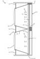
図2は、いくつかの実施形態によるヘッドマウントディスプレイシステム200の斜視図である。いくつかの実施形態では、ヘッドマウントディスプレイシステム200は、ヘッドマウントディスプレイデバイス202、顔インターフェースシステム208、ストラップアセンブリ214、およびオーディオサブシステム216を含み得る。ヘッドマウントディスプレイデバイスは、ユーザの頭部上にまたは頭部の周りに着用され、ユーザに視覚コンテンツを表示する任意のタイプまたは形態のディスプレイデバイスまたはシステムを含み得る。ヘッドマウントディスプレイデバイスは、ディスプレイ要素(たとえば、LCパネル102)を介することを含む、任意の好適な様式でコンテンツを表示し得る。ヘッドマウントディスプレイデバイスはまた、様々なメディアフォーマットのうちの1つまたは複数でコンテンツを表示し得る。たとえば、ヘッドマウントディスプレイデバイスは、ビデオ、写真、および/またはコンピュータ生成画像(CGI)を表示し得る。ヘッドマウントディスプレイデバイス202は、本明細書で説明されるレンズ204および205、ならびにLCパネルおよびバックライトsを含む様々な電子的構成要素を含む、ヘッドマウントディスプレイデバイス202の様々な構成要素を囲んでいるディスプレイハウジング210を含み得る。ディスプレイハウジング210は、内部構成要素を囲んでいるハウジングの後面212および側面と、ディスプレイハウジング210の前側において閲覧領域206を囲んでいる開口とを含み得る。 FIG. 2 is a perspective view of the head-mounted
ヘッドマウントディスプレイデバイスは、多様で特徴的なユーザエクスペリエンスを提供し得る。いくつかのヘッドマウントディスプレイデバイスは、仮想現実エクスペリエンスを提供し得る(すなわち、それらのヘッドマウントディスプレイデバイスは、コンピュータ生成コンテンツまたはあらかじめ記録されたコンテンツを表示し得る)が、他のヘッドマウントディスプレイデバイスは、現実世界エクスペリエンスを提供し得る(すなわち、それらのヘッドマウントディスプレイデバイスは、物理的世界からのライブイメージを表示し得る)。ヘッドマウントディスプレイはまた、ライブコンテンツと仮想コンテンツとの任意の複合を提供し得る。たとえば、仮想コンテンツが(たとえば、光学的またはビデオシースルーを介して)物理的世界上に投影され得、それにより、拡張現実または複合現実エクスペリエンスが生じ得る。ヘッドマウントディスプレイデバイスは、いくつかの仕方でユーザの頭部に取り付けられるように構成され得る。いくつかのヘッドマウントディスプレイデバイスは、グラスまたはバイザーに組み込まれ得る。他のヘッドマウントディスプレイデバイスは、ヘルメット、帽子、または他のヘッドウェアに組み込まれ得る。ヘッドマウントディスプレイデバイスの例は、OCULUS RIFT、GOOGLE GLASS、HTC VIVE、SAMSUNG GEARなどを含み得る。 Head-mounted display devices can provide a diverse and distinctive user experience. Some head-mounted display devices may provide a virtual reality experience (ie, those head-mounted display devices may display computer-generated or pre-recorded content), while other head-mounted display devices may. , May provide a real-world experience (ie, those head-mounted display devices can display live images from the physical world). Head-mounted displays can also provide any composite of live and virtual content. For example, virtual content can be projected onto the physical world (eg, via optical or video see-through), which can result in an augmented reality or mixed reality experience. The head-mounted display device can be configured to be attached to the user's head in several ways. Some head-mounted display devices can be embedded in a glass or visor. Other head-mounted display devices may be incorporated into helmets, hats, or other headwear. Examples of head-mounted display devices may include OCULUS RIFT, GOOGLE GLASS, HTC VIVE, SAMSUNG GEAR and the like.
いくつかの実施形態では、顔インターフェースシステム208は、ヘッドマウントディスプレイシステム200がユーザによって着用されたとき、ユーザの眼を囲んでいる領域を含む、ユーザの顔の領域に対して快適に載るように構成され得る。これらの実施形態では、顔インターフェースシステム208は、ユーザの顔の部分(たとえば、少なくともユーザの鼻、頬、こめかみ、および/または額の顔領域の一部分)に対して載るように構成されたインターフェースクッションを含み得る。顔インターフェースシステム208は、ユーザがヘッドマウントディスプレイシステム200を着用している間、外部光からの干渉なしに、および外部輝度レベルを参照することなしに、ユーザがヘッドマウントディスプレイデバイス202のレンズ204および205を通して見ることを可能にする、ユーザの視野を含む閲覧領域206を囲み得る。少なくとも1つの例では、顔インターフェースシステム208は、ユーザの視線(たとえば、視線方向、視線の原点など)を監視するように構成された1つまたは複数のセンサーを含み得る。 In some embodiments, the
いくつかの実施形態では、ヘッドマウントディスプレイシステム200は、ヘッドマウントディスプレイシステム200の動きに応答して測定信号を生成する1つまたは複数のセンサー(たとえば、加速度計、ジャイロスコープ、磁力計、動きを検出する他の好適なタイプのセンサー、またはそれらの何らかの組合せ)を含み得る。いくつかの例では、ヘッドマウントディスプレイシステム200は、位置センサー、慣性測定ユニット(IMU)、深度カメラアセンブリ、またはそれらの任意の組合せを含み得る。述べられたように、いくつかの人工現実システムは、人工現実を実際の現実とブレンドする代わりに、現実世界についてのユーザの感覚性知覚のうちの1つまたは複数を仮想エクスペリエンスと実質的に交換し得る。いくつかの例では、ヘッドマウントディスプレイシステム200は、ユーザの視野を大部分または完全にカバーし得る。 In some embodiments, the head-mounted
いくつかの実施形態では、ヘッドマウントディスプレイシステム200は、様々なタイプのコンピュータビジョン構成要素およびサブシステムを含み得る。たとえば、ヘッドマウントディスプレイシステム200は、2次元(2D)もしくは3次元(3D)カメラ、飛行時間深度センサー、単一ビームもしくは掃引レーザーレンジファインダー、3D LiDARセンサー、および/または任意の他の好適なタイプまたは形態の光センサーなど、1つまたは複数の光センサーを含み得る。ヘッドマウントディスプレイシステム200は、これらのセンサーのうちの1つまたは複数からのデータを処理して、ユーザのロケーションを識別し、現実世界をマッピングし、現実世界の周囲に関するコンテキストをユーザに提供し、および/または様々な他の機能を実施し得る(たとえば、ヘッドマウントディスプレイシステム200、ヘッドマウントディスプレイシステム200を着用しているユーザのヘッドポーズ、またはユーザの視線の配向または位置に対する変化を決定し得る)。 In some embodiments, the head-mounted
いくつかの実施形態では、ヘッドマウントディスプレイシステム200は、「同時ロケーションおよびマッピング」(SLAM)と呼ばれる技法を使用してユーザの環境をマッピングし、および/または環境内のユーザの動きを追跡し得る。SLAMマッピングおよびロケーション識別技法は、マッピングされた環境内のユーザのロケーションおよび/または配向を同時に追跡しながら、環境のマップを作成または更新することができる、様々なハードウェアおよびソフトウェアツールを伴い得る。SLAMは、マップを作成し、マップ内のユーザの位置を決定するために、多くの異なるタイプのセンサーを使用し得る。SLAM技法は、たとえば、ユーザのロケーションを決定するために光センサーを実装し得る。また、WiFi、Bluetooth、全地球測位システム(GPS)、セルラーまたは他の通信デバイスを含む無線機を使用して、無線トランシーバまたはトランシーバのグループ(たとえば、WiFiルータまたはGPS衛星のグループ)に対してユーザのロケーションを決定し得る。ヘッドマウントディスプレイシステム200は、ユーザの現在の環境のマップを作成し継続的に更新することなどのSLAM動作を実施するために、これらのタイプのセンサーのいずれかまたはすべてを組み込み得る。本明細書で説明される実施形態のうちの少なくともいくつかでは、これらのセンサーによって生成されたSLAMデータは、「環境データ」と呼ばれることがあり、ユーザの現在の環境を示し得る。このデータは、ローカルまたはリモートデータストア(たとえば、クラウドデータストア)に記憶され得、要求に応じてユーザのAR/VRデバイスに提供され得る。 In some embodiments, the head-mounted
図3は、ヘッドマウントディスプレイデバイス202の例示的な断面平面図を図示する。この図に図示されているように、LCパネル102、BLU108、ディスプレイドライバ114、およびバックライトドライバ120が、ヘッドマウントディスプレイデバイス202のディスプレイハウジング210内に配設され得る。LCパネル102は、LCパネル102の表示領域によって生じた画像がレンズ204および205を通してユーザに可視であるように、レンズ204および205に対してディスプレイハウジング210内に配設され得る。図示のように、LCパネル102は、LCパネル102の前面がレンズ204および205のほうへ対向するように、ディスプレイハウジング210中で配置および配向され得る。図示のように、左バックライト110は、LCパネル102の左側104の後ろに配置され得、右バックライト112は、LCパネル102の右側106の後ろに配置され得る。したがって、左バックライト110の発光要素からLCパネル102の左側104を通って放出された光300は、ユーザの左眼に可視であり得、右バックライト112の発光要素からLCパネル102の右側106を通って放出された光302は、ユーザの右眼に可視であり得る。図3には例示されていないが、いくつかの実施形態では、光300および光302を拡散するために、LCパネル102とBLU108との間に光拡散器がはさまれてよい。 FIG. 3 illustrates an exemplary cross-sectional plan view of the head-mounted
図4Aおよび図4Bは、それぞれヘッドマウントディスプレイデバイス202およびLCパネル102の正面図を図示する。図4Aに図示されているように、ヘッドマウントディスプレイデバイス202は、ディスプレイハウジング210内に配設されたLCパネル102などの少なくとも1つのディスプレイを含み得る。いくつかの実施形態では、LCパネル102の別個の部分が、ユーザの眼の各々に可視であり得、各眼に可視の部分は、レンズ204および205とLCパネル102との間に延在している分割領域221(たとえば、個別の眼カップ、中央パーティションなど)によって分離される。そのような構成は、別個の画像がLCパネル102によってユーザの眼の各々に提示されることを可能にし、それにより、3次元画像がユーザによって知覚されることが可能になり得る。 4A and 4B show front views of the head-mounted
図4Aに図示されているように、ヘッドマウントディスプレイデバイス202はまた、レンズ204および205を囲んでいる光遮断パネル219を含み得る。光遮断パネル219は、たとえば、レンズ204および205と、ディスプレイハウジング210の周囲部分との間に延在し得る。光遮断パネル219は、たとえば、ヘッドマウントディスプレイデバイス202の内部構成要素をマスキングし、(たとえば、ユーザの顔と顔インターフェースシステム208との間のギャップを通って)閲覧領域206に偶然入った何らかの外部光が閲覧領域206内で反射されるのを防止する、光吸収物質(たとえば、暗い高分子および/または繊維材料)を含み得る。ディスプレイハウジング210は、LCパネル102、BLU108、および他の電子回路などの内部構成要素を支持および保護する、硬質プラスチックなどの硬質材料を含み得る。 As illustrated in FIG. 4A, the head-mounted
図4Bに図示されているように、LCパネル102は、好適なLCD技術(たとえば、高速スイッチング液晶技術)に従って可視画像を形成するピクセル要素(たとえば、ピクセルおよび/またはサブピクセル)のM×Nアレイを含み得る。図示のように、LCパネル102は、M個のピクセル要素列402と、N個のピクセル要素行400とを含み得る。LCパネル102の各ピクセル要素は、印加電流または電圧に応答して状態(すなわち、液晶の配向)を変化させるLC材料を含み得る。いくつかの例では、画像は、ピクセル要素のLC材料が異なる状態をとり、異なる偏光量が、ピクセル要素の各々を通って放出される光に与えられるように、異なる電流および/または電圧においてピクセル要素を駆動することによってLCパネル102を介して表示され得る。色フィルタアレイパネルのサブピクセル色領域(たとえば、赤色、緑色、および/または青色領域)を通過した光の異なる量を組み合わせることによって多種多様な可視色が生じ得、このようにして、ユーザは、サブピクセル色の組合せに対応する色を知覚する。 As illustrated in FIG. 4B, the
いくつかの実施形態では、ディスプレイドライバ114は、対応する入力信号をLCパネル102の行400の各々に送ることによって、LCパネル102を介して画像を表示し得、入力信号は、行400に沿って行0から行Nに連続的に走査される。これらの入力信号は、行400の各々におけるLC材料を、画像を表示するのに好適な新しい状態に設定し得る。バックライトドライバ120は、以下で説明されるように、行400の一部分のLC材料が新しい状態に完全に遷移した後、行400の一部分の照明を開始し得る。たとえば、バックライトドライバ120は、左側104のLC材料が完全に遷移した後、バックライト110の照明を開始して左側104を照明し得、右側106のLC材料が完全に遷移した後、バックライト112の照明を開始して右側106を照明し得る。 In some embodiments, the
図5Aに図示されているように、BLU108は、可変強度において光を各々放出する発光要素504のM×Nアレイを含み得る。図示のように、BLU108は、M個の発光要素列502と、N個の発光要素行500とを含み得る。図5Bに図示されているように、BLU108の発光要素504の各々は、LCパネル102のピクセル要素の対応するゾーン508を照明するように構成され得る。いくつかの例では、単一の発光要素504によって放出された光を単一の発光要素504の対応するゾーン508にわたって拡散させるために、LCパネル102とBLU108との間に光拡散器506がはさまれてよい。概して、LCパネル102は、より高解像度のパネルであり得、BLUは、より低解像度のパネルであり得る。 As illustrated in FIG. 5A, the
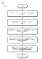
図6は、輝度制御された環境においてバックライトの局所減光を実施するための例示的なコンピュータ実装方法600の流れ図である。図6に図示されているステップは、図1のディスプレイシステム100、図2のヘッドマウントディスプレイデバイス202、および/あるいは同上の1つまたは複数の変形形態または組合せを含む、任意の好適なコンピュータ実行可能コードおよび/またはコンピューティングシステムによって実施され得る。一例では、図6に図示されているステップの各々は、構造が複数のサブステップを含むおよび/または複数のサブステップによって表されるアルゴリズムを表し得、それの例が以下でさらに詳細に提供される。 FIG. 6 is a flow chart of an exemplary
図6に例示されているように、ステップ602において、本明細書で説明される装置またはシステムのうちの1つまたは複数が、ディスプレイパネルを介して表示されるべき画像を受信し得る。たとえば、受信モジュール116が、ディスプレイドライバ114の一部として、LCパネル102を介して表示されるべき画像132を受信し得る。概して、本明細書で説明される装置またはシステムが、ディスプレイパネルを介してユーザに表示すべき一連の画像(たとえば、ビデオフレームのシーケンス)を受信し得る。 As illustrated in FIG. 6, in step 602, one or more of the devices or systems described herein may receive an image to be displayed via the display panel. For example, the receiving module 116 may receive the
ステップ604において、本明細書で説明される装置またはシステムのうちの1つまたは複数が、画像の各画像ブロックの絶対輝度レベルを決定し得る。たとえば、決定モジュール122が、バックライトドライバ120の一部として、画像132の各画像ブロックの絶対輝度レベルを決定し得る。いくつかの例では、「画像ブロック」という用語は、画像の個々のピクセルを指すことがある。他の例では、「画像ブロック」という用語は、バックライトアレイの単一の発光要素によって照明されるディスプレイパネルの一部分を指すことがある。いくつかの例では、「絶対輝度レベル」という用語は、画像のいずれかの部分のグレースケール値、明度値、またはルミナンス値を指すことがある。いくつかの例では、「絶対輝度レベル」という用語は、画像のピクセルのグレースケール値またはルミナンス値を指すことがある。追加または代替として、「絶対輝度レベル」という用語は、特定の色空間における相対ルミナンスのデジタル表現を指すことがある。 In
ステップ606において、本明細書で説明される装置またはシステムのうちの1つまたは複数が、画像の各画像ブロックについて、内部参照輝度レベルに基づいて相対輝度レベルを導出し得る。たとえば、導出モジュール124が、バックライトドライバ120の一部として、画像132の各画像ブロックについて、特定の所定の内部参照輝度レベルに基づいて相対輝度レベルを導出し得る。いくつかの例では、「相対輝度レベル」という用語は、参照輝度レベルに対してである画像のいずれかの部分の輝度レベルを指すことがある。いくつかの例では、「相対輝度レベル」という用語は、閲覧者によって知覚される輝度レベル(たとえば、別の参照グレースケール値、明度値、またはルミナンス値の隣で閲覧されたときの、画像のピクセルの知覚されるグレースケール値、明度値、またはルミナンス値)を指すことがある。いくつかの例では、本明細書で説明される装置またはシステムは、ステップ602において受信された画像の絶対輝度レベルを、その画像の画像ブロックの導出された相対輝度レベルに基づいて調整することによって、ステップ602において受信された画像を、バックライト付きLCDディスプレイを介した表示により好適である補正された画像に変換し、それにより、ステップ602において受信された画像の画像ブロックの絶対輝度レベルと、補正された画像の対応する画像ブロックの絶対輝度レベルとの間の差が、観察者に知覚できないようにし得る。したがって、1人または複数のユーザは、(たとえば、他の外部オブジェクトを見ることのない閉じた環境中で観察された場合)ステップ602において受信された画像と補正された画像との間の差を見分けることができないことがある。 In
本明細書で説明される装置またはシステムは、相対輝度レベルを導出するために様々な内部参照輝度レベルを使用し得る。内部参照輝度レベルの例は、限定はしないが、画像の1つまたは複数の画像ブロックの絶対輝度レベル、画像ブロックのうちの別の1つの相対輝度レベル、既に表示された画像の1つまたは複数の画像ブロックの絶対輝度レベル、および/あるいは既に表示された画像の1つまたは複数の画像ブロックの相対輝度レベルを含み得る。 The device or system described herein may use various internal reference luminance levels to derive relative luminance levels. Examples of internal reference brightness levels are, but are not limited to, the absolute brightness level of one or more image blocks of an image, the relative brightness level of another one of the image blocks, and one or more of the images already displayed. Can include the absolute brightness level of an image block and / or the relative brightness level of one or more image blocks of an already displayed image.
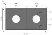
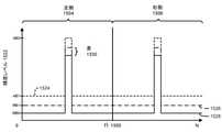
図7は、図8Aに例示されている画像132のピクセルの相対輝度レベルを導出するための例示的な方法を例示する。この例では、画像132は、M個のピクセル列802と、N個のピクセル行800とを含み得、LCパネル102の左側104を介した表示のための左側804と、LCパネル102の右側106を介した表示のための右側806とを含み得る。図7に図示されているように、ステップ702において、本明細書で説明される装置またはシステムが、より低い絶対輝度レベルを有する1つまたは複数の画像ブロックを含む画像の第1の画像領域を識別し得る。たとえば、導出モジュール124が、画像132の列812中のピクセルの輝度レベル822を例示する、図8Bに図示されているAB1に等しい絶対輝度レベルを有する画像ブロックを含む図8Aに例示されている画像132の画像領域810を識別し得る。図8Bに図示されている例では、線824は、画像132の列812中のピクセルの絶対輝度レベルを表し得、線826は、画像132の列812中のピクセルの導出された相対輝度レベルを表し得る。 FIG. 7 illustrates an exemplary method for deriving the relative brightness levels of the pixels of
ステップ704において、本明細書で説明される装置またはシステムが、より高い絶対輝度レベルを有する画像ブロックのうちの1つまたは複数を含む画像の第2の画像領域を識別し得る。たとえば、導出モジュール124が、AB2に等しい絶対輝度レベルを有する画像ブロックを含む図8Aに例示されている画像132の画像領域808を識別し得る。ステップ706において、本明細書で説明される装置またはシステムが、より低い絶対輝度レベルとより高い絶対輝度レベルとの間の差を計算し得る。たとえば、導出モジュール124が、AB1とAB2との間の差828を計算し得る。ステップ708において、本明細書で説明される装置またはシステムが、第1の領域中の画像ブロックの各々について、より低い絶対輝度レベルよりも低い第1の相対輝度レベルを導出し得る。たとえば、導出モジュール124が、領域810中の画像ブロックの各々について、RB1に等しい相対輝度レベルを導出し得る。概して、本明細書で説明される装置またはシステムは、第1の相対輝度レベルとより低い絶対輝度レベルとの間の知覚可能な差がほとんどないかまったくないように、第1の相対輝度レベルの値を選定し得る。ステップ710において、本明細書で説明される装置またはシステムが、第2の領域中の画像ブロックの各々について、第1の相対輝度レベルと差との和に実質的に等しい第2の相対輝度レベルを導出し得る。たとえば、導出モジュール124が、領域808中の画像ブロックの各々について、RB2(すなわち、RB1と差828との和)に等しい相対輝度レベルを導出し得る。 In step 704, the device or system described herein may identify a second image area of an image that includes one or more of the image blocks having higher absolute luminance levels. For example, the derivation module 124 may identify the
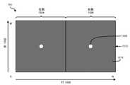
図9は、図10Aに例示されている画像132のピクセルの相対輝度レベルを導出するための例示的な方法を例示する。この例では、画像132は、M個のピクセル列1002と、N個のピクセル行1000とを含み得、LCパネル102の左側104を介した表示のための左側1004と、LCパネル102の右側106を介した表示のための右側1006とを含み得る。図9に図示されているように、ステップ902において、本明細書で説明される装置またはシステムが、より低い絶対輝度レベルを有する1つまたは複数の画像ブロックを含む画像の第1の画像領域を識別し得る。たとえば、導出モジュール124が、画像132の列1012中のピクセルの輝度レベル1022を例示する、図10Bに図示されているAB1に等しい絶対輝度レベルを有するピクセルを含む図10Aに例示されている画像132の画像領域1010を識別し得る。図10Bに図示されている例では、線1024は、画像132の列1012中のピクセルの絶対輝度レベルを表し得、線1026は、画像132の列1012中のピクセルの導出された相対輝度レベルを表し得る。 FIG. 9 illustrates an exemplary method for deriving the relative luminance levels of the pixels of
ステップ904において、本明細書で説明される装置またはシステムが、より高い絶対輝度レベルを有する画像ブロックのうちの1つまたは複数を含む画像の第2の画像領域を識別し得る。たとえば、導出モジュール124が、AB2に等しい絶対輝度レベルを有するピクセルを含む図10Aに例示されている画像132の画像領域1008を識別し得る。ステップ906において、本明細書で説明される装置またはシステムが、第2の画像領域について、閲覧者によって知覚されたとき、単一の輝度レベルとして実質的に見える輝度レベル勾配(たとえば、漸進的に増加または減少する一連の輝度レベル)を導出し得る。たとえば、導出モジュール124が、画像領域1008について、閲覧者によって知覚されたとき、輝度レベルAB2として実質的に見える輝度レベル勾配1028および輝度レベル勾配1030を導出し得る。別の例では、導出モジュール124は、画像領域1008について、閲覧者によって知覚されたとき、輝度レベルAB2として実質的に見える図11に例示されている輝度レベル勾配1102および輝度レベル勾配1104を導出し得る。ステップ908において、本明細書で説明される装置またはシステムは、第1の画像領域から最も遠い第2の画像領域内の画像ブロックが、最も高い輝度レベルを有し、第1の画像領域に最も近い第2の画像領域内の画像ブロックが、最も低い輝度を有するように、輝度レベル勾配からの輝度レベルを画像ブロックのうちの2つ以上に割り当て得る。たとえば、導出モジュール124は、画像領域1010から最も遠い画像領域1008内のピクセルが、最も高い輝度レベルを有し、画像領域1010に最も近い画像領域1008内のピクセルが、最も低い輝度レベルを有するように、輝度レベル勾配1028および1030からの輝度レベルを、図示のように画像領域1008に対応する列1012に沿ったピクセルに割り当て得る。 In step 904, the device or system described herein may identify a second image area of an image that includes one or more of the image blocks having higher absolute luminance levels. For example, the derivation module 124 may identify the
図12は、図13Aに例示されている画像132のピクセルの相対輝度レベルを導出するための例示的な方法を例示する。この例では、画像132は、M個のピクセル列1302と、N個のピクセル行1300とを含み得る。画像132はまた、LCパネル102の左側104を介した表示のための左側1304と、LCパネル102の右側106を介した表示のための右側1306とを含み得る。図12に図示されているように、ステップ1202において、本明細書で説明される装置またはシステムが、より高い絶対輝度レベルを有する画像の第1の画像領域を識別し得る。たとえば、導出モジュール124が、画像132の列1312中のピクセルの輝度レベル1322を例示する、図13Bに図示されているAB2に等しい絶対輝度レベルを有するピクセルを含む図13Aに例示されている画像132の画像領域1308を識別し得る。図13Bに図示されている例では、線1324は、画像132の列1312中のピクセルの絶対輝度レベルを表し得、線1326は、画像132の列1312中のピクセルの導出された相対輝度レベルを表し得る。 FIG. 12 illustrates an exemplary method for deriving the relative luminance levels of the pixels of
ステップ1204において、本明細書で説明される装置またはシステムが、実質的に同様のより低い絶対輝度レベルを有する2つ以上の画像ブロックを含む画像の第2の画像領域を識別し得る。たとえば、導出モジュール124が、AB1に等しい絶対輝度レベルを有するピクセルを含む図13Aに例示されている画像132の画像領域1310を識別し得る。ステップ1206において、本明細書で説明される装置またはシステムが、第2の画像領域について、閲覧者によって知覚されたとき、単一の輝度レベルとして実質的に見える輝度レベル勾配を導出し得る。たとえば、導出モジュール124が、画像領域1310について、閲覧者によって知覚されたとき、輝度レベルAB1として実質的に見える輝度レベル勾配1328および輝度レベル勾配1330を導出し得る。ステップ1208において、本明細書で説明される装置またはシステムは、第1の画像領域から最も遠い第2の画像領域内の画像ブロックが、最も低い輝度レベルを有し、第1の画像領域に最も近い第2の画像領域内の画像ブロックが、最も高い輝度レベルを有するように、輝度レベル勾配からの輝度レベルを画像ブロックのうちの2つ以上に割り当て得る。たとえば、導出モジュール124は、画像領域1308から最も遠い画像領域1310内のピクセルが、最も低い輝度レベルを有し、画像領域1308に最も近い画像領域1310内のピクセルが、最も高い輝度レベルを有するように、輝度レベル勾配1328および1330からの輝度レベルを、図示のように画像領域1310に対応する列1312に沿ったピクセルに割り当て得る。 In step 1204, the device or system described herein may identify a second image area of an image containing two or more image blocks with substantially similar lower absolute luminance levels. For example, the derivation module 124 may identify the
図14は、図15Aに例示されている画像134のピクセルの相対輝度レベルを導出するための例示的な方法を例示する。この例では、画像134は、少なくとも絶対輝度レベルに関して、画像132と実質的に同様であるLCパネル102を介して表示される後続の画像を表し得る。画像132のように、画像134は、M個のピクセル列1502と、N個のピクセル行1500とを含み得、LCパネル102の左側104を介した表示のための左側1504と、LCパネル102の右側106を介した表示のための右側1506とを含み得る。図14に図示されているように、ステップ1402において、本明細書で説明される装置またはシステムが、第1の絶対輝度レベルを有する画像の画像ブロックを識別し得る。たとえば、導出モジュール124が、画像134の列1512中のピクセルの輝度レベル1522を例示する、図15Bに図示されているAB1に等しい絶対輝度レベルを有する図15Aに例示されている画像134の画像領域1510内のピクセルを識別し得る。図15Bに図示されている例では、線1524は、図8Aの画像134の列1512中のピクセルおよび画像132の列812中のピクセルの絶対輝度レベルを表し得、線1526は、画像132の列812中のピクセルの導出された相対輝度レベルを表し得、線1528は、画像134の列1512中のピクセルの導出された相対輝度レベルを表し得る。 FIG. 14 illustrates an exemplary method for deriving the relative brightness levels of the pixels of
ステップ1404において、本明細書で説明される装置またはシステムが、第1の絶対輝度レベルに実質的に等しい第2の絶対輝度レベルを有する追加の画像の画像ブロックを識別し得る。たとえば、導出モジュール124が、図8Bに図示されているAB1に等しい絶対輝度レベルを有する図8Aに例示されている画像132の画像領域810内のピクセルを識別し得る。ステップ1406において、本明細書で説明される装置またはシステムが、追加の画像の画像ブロックの相対輝度レベルを決定し得る。たとえば、導出モジュール124は、図8Aに例示されている画像132の画像領域810内のピクセルの相対輝度が、図8Bに図示されているRB1に等しいと決定し得る。 In
ステップ1408において、本明細書で説明される装置またはシステムは、追加の画像の画像ブロックの相対輝度レベルと画像の画像ブロックの相対輝度レベルとの間の差が、閲覧者にとって実質的に知覚できないように、追加の画像の画像ブロックの相対輝度レベルよりも低い画像の画像ブロックの相対輝度レベルを導出し得る。たとえば、導出モジュール124は、RB1とRB0との間の差1530が、画像134の閲覧者にとって実質的に知覚できないように、図15Aに例示されている画像134の画像領域1510内のピクセルについてRB0に等しい相対輝度レベルを導出し得る。 In
図6に戻ると、ステップ608において、本明細書で説明される装置またはシステムのうちの1つまたは複数が、ディスプレイパネルのバックライトの各発光要素について、画像の画像ブロックの対応する部分の相対輝度レベルに基づいて照明レベルを計算し得る。たとえば、計算モジュール126が、バックライトドライバ120の一部として、画像132の部分508の相対輝度レベルに基づいてBLU108の発光要素504の照明レベルを計算し得る。いくつかの例では、計算される照明レベルは、上記で説明された補正された画像から導出され得る。 Returning to FIG. 6, in
いくつかの例では、本明細書で説明される装置またはシステムのうちの1つまたは複数は、ユーザに発展的3次元仮想シーンを提示するように構成されたディスプレイデバイスを含み得る。これらの例では、本明細書で説明される装置またはシステムは、相対輝度レベルに基づいて照明レベルを計算することの追加または代替として、ディスプレイデバイスの動き、発展的3次元仮想シーンに対するユーザのヘッドポーズの動き、ユーザの視線の動き、および/あるいは発展的3次元仮想シーン中の要素のうちの1つまたは複数の動きに基づいて照明レベルを計算し得る。いくつかの例では、発展的3次元仮想シーンを表示するディスプレイデバイスの移動、発展的3次元仮想シーンに対するユーザのヘッドポーズの移動、ユーザの視線の移動、ならびに/あるいは(導出された2D動きベクトルおよび/または深度マップ情報を使用して検出可能であり得る)発展的3次元仮想シーン中の要素の移動は、発展的3次元仮想シーンを描写している画像中の要素のうちの1つまたは複数の予測可能な移動を引き起こし得る。したがって、本明細書で説明される装置またはシステムのうちの1つまたは複数は、発展的3次元仮想シーンを描写している画像中の要素のうちの1つまたは複数の移動を予測して、現在の画像中でまたは後続の画像中でこれらの要素を照明するための照明レベルを正しく計算し得る。たとえば、本明細書で説明される装置またはシステムは、より正確/アグレッシブなLED+LCD調整をもたらすために、眼およびオブジェクトの動きの知識を使用して後続の画像(N+1)中の光領域の位置をより正確に予測し得る。少なくとも1つの例では、ディスプレイデバイスを介して表示される画像内の移動を考慮することによって、本明細書で説明される装置またはシステムは、本来なら移動によって引き起こされるはずである時間的バックライティングアーティファクト(たとえば、迅速に動いている明るいオブジェクトによって引き起こされるゴースト痕跡)を低減するかまたはなくす仕方で照明レベルを計算し得る。 In some examples, one or more of the devices or systems described herein may include a display device configured to present an evolving 3D virtual scene to the user. In these examples, the device or system described herein is the user's head to the movement of the display device, an evolving 3D virtual scene, as an addition or alternative to calculating the illumination level based on the relative brightness level. Illumination levels can be calculated based on the movement of the pose, the movement of the user's line of sight, and / or the movement of one or more of the elements in the evolving 3D virtual scene. In some examples, moving the display device to display the evolving 3D virtual scene, moving the user's head pose to the evolving 3D virtual scene, moving the user's line of sight, and / or (derived 2D motion vector). Movement of elements in an evolving 3D virtual scene (which may be detectable using depth map information and / or) is one of the elements in the image depicting the evolving 3D virtual scene or Can cause multiple predictable movements. Accordingly, one or more of the devices or systems described herein predicts the movement of one or more of the elements in an image depicting an evolving 3D virtual scene. The illumination level for illuminating these elements in the current image or in subsequent images can be calculated correctly. For example, the device or system described herein uses knowledge of eye and object movement to position the optical region in a subsequent image (N + 1) in order to provide more accurate / aggressive LED + LCD adjustments. It can be predicted more accurately. In at least one example, by considering movement within an image displayed through a display device, the device or system described herein is a temporal backlighting artifact that would otherwise be caused by movement. Illumination levels can be calculated in ways that reduce or eliminate (eg, ghost traces caused by fast-moving bright objects).
ステップ610において、本明細書で説明される装置またはシステムのうちの1つまたは複数は、画像がディスプレイパネルを介して表示されている間、発光要素について計算された照明レベルに従ってバックライトアレイの発光要素の各々を照明させ得る。たとえば、照明モジュール128は、バックライトドライバ120の一部として、画像132がLCパネル102を介して表示されている間、ステップ608において計算された照明レベルに従って発光要素504の各々を照明させ得る。いくつかの例では、バックライトアレイは、バックライトアレイが照明する画像の画像ブロックの数よりもはるかに少数の発光要素を有し得る。したがって、単一の照明レベルを有し得る、バックライトアレイの発光要素の各々は、異なる輝度レベルを各々有する画像の複数の画像ブロックを照明する必要があり得る。少なくともこの理由により、本明細書で説明される装置またはシステムのうちの1つまたは複数は、画像を表示し照明する前に、これらの差を補償し得る。たとえば、本明細書で説明される装置またはシステムのうちの1つまたは複数は、上記で計算された照明レベルに従って照明されたとき、一様に照明されるバックライトアレイによって照明された場合に、補正された画像の光学濃度界と等価な光学濃度界を生じることになる画像を決定することによって、上記で説明された補正された画像を、表示およびバックライトされる準備ができている最終画像に変換し得る。 In step 610, one or more of the devices or systems described herein emit light from the backlight array according to the illumination level calculated for the light emitting element while the image is displayed through the display panel. Each of the elements can be illuminated. For example, the
いくつかの例では、本明細書で説明される装置またはシステムのうちの1つまたは複数は、発展的3次元仮想シーンを描写している画像をユーザに提示するように構成されたディスプレイデバイスを含み得る。そのような例では、ディスプレイデバイスの移動、発展的3次元仮想シーンに対するユーザのヘッドポーズの移動、ユーザの視線の移動、および/または発展的3次元仮想シーン中の要素の移動は、画像中の要素のうちの1つまたは複数の予測可能な移動を引き起こし得る。したがって、本明細書で説明される装置またはシステムのうちの1つまたは複数は、発展的3次元仮想シーンを描写している画像中の要素のうちの1つまたは複数の移動を予測することによって、画像(または補正された画像)を、表示およびバックライトされる準備ができている最終画像に変換して、要素の動きを補償し得る。少なくとも1つの例では、ディスプレイデバイスを介して表示される画像内の移動を考慮することによって、本明細書で説明される装置またはシステムは、本来なら移動によって引き起こされるはずである時間的バックライティングアーティファクト(たとえば、迅速に動いている明るいオブジェクトによって引き起こされるゴースト痕跡)を低減するかまたはなくす仕方で画像を変換し得る。 In some examples, one or more of the devices or systems described herein is a display device configured to present the user with an image depicting an evolving 3D virtual scene. Can include. In such an example, the movement of the display device, the movement of the user's head pose to the evolving 3D virtual scene, the movement of the user's line of sight, and / or the movement of the elements in the evolving 3D virtual scene are in the image. It can cause one or more predictable movements of the element. Accordingly, one or more of the devices or systems described herein by predicting the movement of one or more of the elements in an image depicting an evolving 3D virtual scene. The image (or corrected image) can be transformed into a final image ready to be displayed and backlit to compensate for element movement. In at least one example, by considering movement within an image displayed through a display device, the device or system described herein is a temporal backwriting artifact that would otherwise be caused by movement. Images can be transformed in ways that reduce or eliminate (eg, ghost traces caused by fast-moving bright objects).
図16は、輝度制御された環境においてバックライトの局所減光を実施するための例示的なコンピュータ実装方法1600の流れ図である。図16に図示されているステップは、図1のディスプレイシステム100、図2のヘッドマウントディスプレイデバイス202、および/あるいは同上の1つまたは複数の変形形態または組合せを含む、任意の好適なコンピュータ実行可能コードおよび/またはコンピューティングシステムによって実施され得る。一例では、図16に図示されているステップの各々は、構造が複数のサブステップを含むおよび/または複数のサブステップによって表されるアルゴリズムを表し得、それの例が以下でさらに詳細に提供される。 FIG. 16 is a flow chart of an exemplary
図16に例示されているように、ステップ1602において、本明細書で説明される装置またはシステムのうちの1つまたは複数が、ディスプレイパネルを介して表示されるべき画像を受信し得る。たとえば、受信モジュール116が、ディスプレイドライバ114の一部として、LCパネル102を介して表示されるべき画像132を受信し得る。ステップ1604において、本明細書で説明される装置またはシステムのうちの1つまたは複数が、画像の各画像ブロックの絶対輝度レベルを決定し得る。たとえば、決定モジュール122が、バックライトドライバ120の一部として、画像132の各画像ブロックの絶対輝度レベルを決定し得る。 As illustrated in FIG. 16, in step 1602, one or more of the devices or systems described herein may receive an image to be displayed via the display panel. For example, the receiving module 116 may receive the
ステップ1606において、本明細書で説明される装置またはシステムのうちの1つまたは複数が、画像ブロックの各々について、相対輝度レベルを計算するために人間の輝度知覚のモデルを使用し得る。たとえば、導出モジュール124が、画像132の各画像ブロックについて、相対輝度レベルを導出するために、バックライトドライバ120の一部として知覚モデル130を使用し得る。いくつかの例では、「人間の輝度知覚のモデル」という用語は、画像の画像ブロックの絶対輝度レベルまたは相対輝度レベル、あるいは既に表示された画像の画像ブロックの絶対輝度レベルまたは相対輝度レベルに基づいて画像の画像ブロックの相対輝度レベルを計算するために使用され得る、任意のアルゴリズム、ヒューリスティック、データ、またはそれらの組合せを指すことがある。いくつかの例では、本明細書で説明される装置またはシステムのうちの1つまたは複数は、(たとえば、他の外部オブジェクトを見ることのない閉じた環境中で観察されたとき)1人または複数のユーザが差を見分けることができなかった画像の2つのセットを比較することによって、人間の輝度知覚のモデルを経験的に作成し得る。追加または代替として、本明細書で説明される装置またはシステムのうちの1つまたは複数は、人間の眼および/または脳の生物学に関する科学的観察(たとえば、どのようにして人間の視覚システムが、明るいオブジェクト上の広範囲の輝度勾配に対して鈍感であり得るか、またはその広範囲の輝度勾配を補償することが可能であり得るかに関する観察)に基づいて人間の輝度知覚のモデルを作成し得る。 In step 1606, one or more of the devices or systems described herein may use a model of human luminance perception to calculate relative luminance levels for each of the image blocks. For example, the derivation module 124 may use the
いくつかの例では、本明細書で説明される装置またはシステムのうちの1つまたは複数は、閲覧者がどのように光度勾配を知覚するかをモデル化または予測するために、人間の輝度知覚のモデルをトレーニングし得る。これらの例では、本明細書で説明される装置またはシステムのうちの1つまたは複数は、モデルを使用して、閲覧者によって知覚されたとき、単一の輝度レベルとして実質的に見える上記で説明された輝度レベル勾配を導出し得る。追加または代替として、本明細書で説明される装置またはシステムのうちの1つまたは複数は、閲覧者がどのように参照輝度レベルに基づいて絶対輝度レベルを知覚するかをモデル化または予測するために、人間の輝度知覚のモデルをトレーニングし得る。いくつかの例では、本明細書で説明される装置またはシステムのうちの1つまたは複数は、モデルを使用して、閲覧者にとって実質的に知覚できない上記で説明された輝度レベル間の差を導出し得る。 In some examples, one or more of the devices or systems described herein is a human brightness perception to model or predict how the viewer perceives a luminosity gradient. Can train your model. In these examples, one or more of the devices or systems described herein are substantially visible as a single brightness level when perceived by the viewer using the model above. The described luminance level gradient can be derived. As an addition or alternative, one or more of the devices or systems described herein is to model or predict how the viewer perceives an absolute luminance level based on the reference luminance level. In addition, a model of human luminance perception can be trained. In some examples, one or more of the devices or systems described herein use the model to make differences between the luminance levels described above that are virtually imperceptible to the viewer. Can be derived.
ステップ1608において、本明細書で説明される装置またはシステムのうちの1つまたは複数が、ディスプレイパネルのバックライトの各発光要素について、画像の画像ブロックの対応する部分の相対輝度レベルに基づいて照明レベルを計算し得る。たとえば、計算モジュール126が、バックライトドライバ120の一部として、画像132の対応する部分508の相対輝度レベルに基づいてBLU108の発光要素504の照明レベルを計算し得る。ステップ1610において、本明細書で説明される装置またはシステムのうちの1つまたは複数は、画像がディスプレイパネルを介して表示されている間、発光要素について計算された照明レベルに従ってバックライトアレイの発光要素の各々を照明させ得る。たとえば、照明モジュール128は、バックライトドライバ120の一部として、画像132がLCパネル102を介して表示されている間、ステップ1608において計算された照明レベルに従って発光要素504の各々を照明させ得る。 In
本開示全体にわたって論じられたように、開示される装置、システム、および方法は、従来のディスプレイ装置、システム、および方法に勝る1つまたは複数の利点を提供し得る。たとえば、本開示の実施形態は、従来の局所バックライティング技法を実装するLCDにおいて見出される視覚的不備の多くを低減するかまたはなくし得る。その上、開示される局所バックライト減光技法は、暗い背景上の高速移動オブジェクトもしくは明るいオブジェクトの快適な観察を可能にし、VRディスプレイの電力消費量を低減し、および/またはVRシーンの知覚されるコントラストを著しく増加させ得る。 As discussed throughout this disclosure, the disclosed devices, systems, and methods may offer one or more advantages over conventional display devices, systems, and methods. For example, embodiments of the present disclosure may reduce or eliminate many of the visual deficiencies found in LCDs that implement conventional topical backwriting techniques. Moreover, the disclosed local backlight dimming technique allows comfortable observation of fast moving or bright objects on dark backgrounds, reduces power consumption of VR displays, and / or is perceived in VR scenes. Can significantly increase the contrast.
上記で詳述されたように、本明細書で説明および/または例示されるコンピューティングデバイスおよびシステムは、本明細書で説明されるモジュール内に含まれているものなど、コンピュータ可読命令を実行することが可能な任意のタイプまたは形態のコンピューティングデバイスまたはシステムを広く表す。それらの最も基本的な構成では、これらのコンピューティングデバイスは、少なくとも1つのメモリデバイスと、少なくとも1つの物理的プロセッサとを各々含み得る。 As detailed above, the computing devices and systems described and / or exemplified herein perform computer-readable instructions, such as those contained within the modules described herein. Broadly represents any type or form of computing device or system that can be. In their most basic configuration, these computing devices may each include at least one memory device and at least one physical processor.
いくつかの例では、「メモリデバイス」という用語は、概して、データおよび/またはコンピュータ可読命令を記憶することが可能な任意のタイプまたは形態の揮発性または不揮発性記憶デバイスまたは媒体を指す。一例では、メモリデバイスは、本明細書で説明されるモジュールのうちの1つまたは複数を記憶、ロード、および/または維持し得る。メモリデバイスの例は、限定はしないが、ランダムアクセスメモリ(RAM)、読取り専用メモリ(ROM)、フラッシュメモリ、ハードディスクドライブ(HDD)、ソリッドステートドライブ(SSD)、光ディスクドライブ、キャッシュ、同上の1つまたは複数の変形形態または組合せ、あるいは任意の他の好適な記憶メモリを含む。 In some examples, the term "memory device" generally refers to any type or form of volatile or non-volatile storage device or medium capable of storing data and / or computer-readable instructions. In one example, the memory device may store, load, and / or retain one or more of the modules described herein. Examples of memory devices are, but not limited to, random access memory (RAM), read-only memory (ROM), flash memory, hard disk drive (HDD), solid state drive (SSD), optical disk drive, cache, and one of the same. Or include multiple variants or combinations, or any other suitable storage memory.
いくつかの例では、「物理的プロセッサ」という用語は、概して、コンピュータ可読命令を解釈および/または実行することが可能な任意のタイプまたは形態のハードウェア実装処理ユニットを指す。一例では、物理的プロセッサは、上記で説明されたメモリデバイスに記憶された1つまたは複数のモジュールにアクセスしおよび/またはモジュールを修正し得る。物理的プロセッサの例は、限定はしないが、マイクロプロセッサ、マイクロコントローラ、中央処理ユニット(CPU)、ソフトコアプロセッサを実装するフィールドプログラマブルゲートアレイ(FPGA)、特定用途向け集積回路(ASIC)、同上の1つまたは複数の部分、同上の1つまたは複数の変形形態または組合せ、あるいは任意の他の好適な物理的プロセッサを含む。 In some examples, the term "physical processor" generally refers to any type or form of hardware implementation processing unit capable of interpreting and / or executing computer-readable instructions. In one example, the physical processor may access and / or modify one or more modules stored in the memory device described above. Examples of physical processors are, but are not limited to, microprocessors, microcontrollers, central processing units (CPUs), field programmable gate arrays (FPGAs) that implement softcore processors, application-specific integrated circuits (ASICs), ibid. Includes one or more parts, one or more variants or combinations of the same, or any other suitable physical processor.
別個の要素として例示されているが、本明細書で説明および/または例示されるモジュールは、単一のモジュールまたはアプリケーションの部分を表し得る。加えて、いくつかの実施形態では、これらのモジュールのうちの1つまたは複数は、コンピューティングデバイスによって実行されたとき、コンピューティングデバイスに、1つまたは複数のタスクを実施させ得る1つまたは複数のソフトウェアアプリケーションまたはプログラムを表し得る。たとえば、本明細書で説明および/または例示されるモジュールのうちの1つまたは複数は、本明細書で説明および/または例示されるコンピューティングデバイスまたはシステムのうちの1つまたは複数上で走らされるように記憶および構成されたモジュールを表し得る。これらのモジュールのうちの1つまたは複数はまた、1つまたは複数のタスクを実施するように構成された1つまたは複数の専用コンピュータのすべてまたは部分を表し得る。 Although exemplified as separate elements, the modules described and / or exemplified herein may represent a single module or part of an application. In addition, in some embodiments, one or more of these modules may cause the computing device to perform one or more tasks when performed by the computing device. Can represent a software application or program. For example, one or more of the modules described and / or exemplified herein may be run on one or more of the computing devices or systems described and / or exemplified herein. It can represent a module that is stored and configured as such. One or more of these modules may also represent all or part of one or more dedicated computers configured to perform one or more tasks.
加えて、本明細書で説明されるモジュールのうちの1つまたは複数は、データ、物理的デバイス、および/または物理的デバイスの表現を、1つの形態から別の形態に変換し得る。たとえば、本明細書で具陳されるモジュールのうちの1つまたは複数は、LCパネルを介して表示されるべき画像を受信し、画像をLCパネルのバックライトアレイの発光要素のための照明レベルに変換し、変換の結果をLCパネルのバックライトアレイに出力し、画像がLCパネルを介して表示されている間、変換の結果を使用して画像を照明し得る。追加または代替として、本明細書で具陳されるモジュールのうちの1つまたは複数は、コンピューティングデバイス上で実行し、コンピューティングデバイス上にデータを記憶し、および/または他の方法でコンピューティングデバイスと相互作用することによって、プロセッサ、揮発性メモリ、不揮発性メモリ、および/または物理的コンピューティングデバイスの任意の他の部分を、1つの形態から別の形態に変換し得る。 In addition, one or more of the modules described herein may transform data, physical devices, and / or representations of physical devices from one form to another. For example, one or more of the modules specified herein receive an image to be displayed via the LC panel and the image is the illumination level for the light emitting element of the backlight array of the LC panel. The result of the conversion can be used to illuminate the image while it is converted to and the result of the conversion is output to the backlight array of the LC panel and the image is displayed through the LC panel. As an addition or alternative, one or more of the modules set forth herein may run on a computing device, store data on the computing device, and / or otherwise compute. By interacting with the device, any other part of the processor, volatile memory, non-volatile memory, and / or physical computing device can be transformed from one form to another.
いくつかの実施形態では、「コンピュータ可読媒体」という用語は、概して、コンピュータ可読命令を記憶または搬送することが可能な任意の形態のデバイス、キャリア、または媒体を指す。コンピュータ可読媒体の例は、限定はしないが、搬送波などの伝送型媒体、および磁気記憶媒体(たとえば、ハードディスクドライブ、テープドライブ、およびフロッピーディスク)、光記憶媒体(たとえば、コンパクトディスク(CD)、デジタルビデオディスク(DVD)、およびBLU-RAYディスク)、電子記憶媒体(たとえば、ソリッドステートドライブおよびフラッシュ媒体)などの非一時型媒体、ならびに他の配信システムを含む。 In some embodiments, the term "computer-readable medium" generally refers to any form of device, carrier, or medium capable of storing or carrying computer-readable instructions. Examples of computer-readable media include, but are not limited to, transmission media such as carriers, magnetic storage media (eg, hard disk drives, tape drives, and floppy disks), optical storage media (eg, compact discs (CDs), digital). Includes non-temporary media such as video discs (DVDs) and BLU-RAY discs), electronic storage media (eg, solid state drives and flash media), and other distribution systems.
本開示の実施形態は、人工現実システムを含むかまたは人工現実システムと併せて実装され得る。人工現実は、たとえば、仮想現実(VR)、拡張現実(AR)、複合現実(MR)、ハイブリッド現実、あるいはそれらの何らかの組合せおよび/または派生物を含み得る、ユーザへの提示の前に何らかの様式で調整された現実の形態である。人工現実コンテンツは、完全に生成されたコンテンツ、またはキャプチャされた(たとえば、現実世界の)コンテンツと組み合わされた生成されたコンテンツを含み得る。人工現実コンテンツは、ビデオ、オーディオ、ハプティックフィードバック、またはそれらの何らかの組合せを含み得、それらのいずれも、単一のチャネルにおいて、または(閲覧者に対して3次元効果を生じるステレオビデオなどの)複数のチャネルにおいて提示され得る。さらに、いくつかの実施形態では、人工現実はまた、たとえば、人工現実におけるコンテンツを作成するために使用され、および/または人工現実において(たとえば、活動を実施する際に)他の方法で使用される、アプリケーション、製品、アクセサリー、サービス、またはそれらの何らかの組合せに関連付けられてよい。人工現実コンテンツを提供する人工現実システムは、1人または複数の閲覧者に人工現実コンテンツを提供することが可能な、ホストコンピュータシステムに接続されたヘッドマウントディスプレイ(HMD)、スタンドアロンHMD、モバイルデバイスもしくはコンピューティングシステム、または任意の他のハードウェアプラットフォームを含む、様々なプラットフォーム上で実装され得る。 The embodiments of the present disclosure may include or be implemented in conjunction with an artificial reality system. Artificial reality may include, for example, virtual reality (VR), augmented reality (AR), mixed reality (MR), hybrid reality, or any combination and / or derivative thereof, in any manner prior to presentation to the user. It is a form of reality adjusted by. Artificial reality content can include fully generated content or generated content combined with captured (eg, real-world) content. Artificial reality content can include video, audio, haptic feedback, or any combination thereof, all in a single channel or in multiples (such as stereo video that produces a three-dimensional effect for the viewer). Can be presented in the channel of. In addition, in some embodiments, artificial reality is also used, for example, to create content in artificial reality, and / or in other ways (eg, when performing activities) in artificial reality. May be associated with an application, product, accessory, service, or any combination thereof. An artificial reality system that provides artificial reality content is a head-mounted display (HMD), stand-alone HMD, mobile device, or capable of providing artificial reality content to one or more viewers. It can be implemented on a variety of platforms, including computing systems, or any other hardware platform.
本明細書で説明および/または例示されるステップのプロセスパラメータおよびシーケンスは、例のみとして与えられ、必要に応じて変更されることが可能である。たとえば、本明細書で例示および/または説明されるステップは、特定の順序で図示されるかまたは論じられることがあるが、これらのステップは、必ずしも、例示されるかまたは論じられる順序で実施される必要はない。本明細書で説明および/または例示される様々な例示的な方法はまた、本明細書で説明または例示されるステップのうちの1つまたは複数を省略するか、あるいは開示されるステップに加えて追加のステップを含んでよい。 The process parameters and sequences of the steps described and / or exemplified herein are given by way of example only and can be modified as needed. For example, the steps exemplified and / or described herein may be illustrated or discussed in a particular order, but these steps are not necessarily performed in the order illustrated or discussed. There is no need to. The various exemplary methods described and / or exemplified herein also omit one or more of the steps described or exemplified herein, in addition to the steps disclosed. It may include additional steps.
先の説明は、他の当業者が、本明細書で開示される例示的な実施形態の様々な態様を最良に利用することを可能にするために提供された。この例示的な説明は、網羅的であること、または開示されるいかなる厳密な形態にも限定されることを意図されていない。多くの修正および変更が、本開示の趣旨および範囲から逸脱することなく可能である。本明細書において開示される実施形態は、あらゆる点において、限定的ではなく例示的であると見なされるべきである。本開示の範囲を決定する際には、添付の特許請求の範囲およびその均等物への参照が行われるべきである。 The above description has been provided to allow other skill in the art to make the best use of various aspects of the exemplary embodiments disclosed herein. This exemplary description is not intended to be exhaustive or limited to any exact form disclosed. Many amendments and changes are possible without departing from the spirit and scope of this disclosure. The embodiments disclosed herein should be considered in all respects as exemplary rather than limiting. References to the appended claims and their equivalents should be made in determining the scope of this disclosure.
別段に記載されていない限り、本明細書および特許請求の範囲において使用される「に接続される」および「に結合される」という用語(ならびにそれらの派生語)は、直接接続と、間接的(すなわち、他の要素または構成要素を介した)接続の両方を許可するものとして解釈されたい。加えて、本明細書および特許請求の範囲において使用される「a」または「an」という用語は、「のうちの少なくとも1つ」を意味するものとして解釈されたい。最後に、使いやすさのために、本明細書および特許請求の範囲において使用される「含む」および「有する」という用語(ならびにそれらの派生語)は、「備える」という単語と交換可能であり、同じ意味を有する。 Unless otherwise stated, the terms "connected to" and "bound to" (and their derivatives) as used herein and in the claims are direct and indirect. It should be interpreted as allowing both connections (ie, via other elements or components). In addition, the terms "a" or "an" as used herein and in the claims should be construed to mean "at least one of". Finally, for ease of use, the terms "include" and "have" (and their derivatives) as used herein and in the claims are interchangeable with the word "provide". , Have the same meaning.
Claims (15)
Translated fromJapanese前記画像が、複数のピクセル領域を備えるディスプレイパネルを介して表示されるべきであり、
バックライトアレイが、前記複数のピクセル領域の後ろで前記ディスプレイパネルに結合され、前記複数のピクセル領域の対応する部分を照明するように各々構成された複数の発光要素を備え、
前記ディスプレイパネルおよび前記バックライトアレイが、閲覧者が外部輝度レベルを参照するのを実質的に防止するように構成された、
画像を受信することと、
前記複数の画像ブロックの各々の絶対輝度レベルを決定することと、
前記複数の画像ブロックの各々について、少なくとも1つの内部参照輝度レベルに少なくとも部分的に基づいて相対輝度レベルを導出することと、
前記複数の発光要素の各々について、前記複数の画像ブロックの対応する部分の前記相対輝度レベルに少なくとも部分的に基づいて照明レベルを計算することと、
前記画像が前記ディスプレイパネルを介して表示されている間、前記発光要素について計算された前記照明レベルに従って前記複数の発光要素の各々を照明させることと、
を含むコンピュータ実装方法。Receiving an image with multiple image blocks,
The image should be displayed via a display panel with multiple pixel areas.
The backlight array comprises a plurality of light emitting elements coupled to the display panel behind the plurality of pixel areas and each configured to illuminate the corresponding portion of the plurality of pixel areas.
The display panel and the backlight array are configured to substantially prevent the viewer from referencing an external luminance level.
Receiving images and
Determining the absolute luminance level of each of the plurality of image blocks
For each of the plurality of image blocks, deriving the relative luminance level at least partially based on at least one internal reference luminance level.
For each of the plurality of light emitting elements, calculating the illumination level based at least partially on the relative brightness level of the corresponding portion of the plurality of image blocks.
While the image is displayed through the display panel, each of the plurality of light emitting elements is illuminated according to the illumination level calculated for the light emitting element.
Computer implementation method including.
より低い絶対輝度レベルを有する前記複数の画像ブロックのうちの1つまたは複数を備える前記画像の第1の画像領域を識別することと、
より高い絶対輝度レベルを有する前記複数の画像ブロックのうちの1つまたは複数を備える前記画像の第2の画像領域を識別することと、
前記より低い絶対輝度レベルと前記より高い絶対輝度レベルとの間の差を計算することと、
前記第1の領域中の前記複数の画像ブロックの各々について、前記より低い絶対輝度レベルよりも低い第1の相対輝度レベルを導出することと、
前記第2の領域中の前記複数の画像ブロックの各々について、前記第1の相対輝度レベルと前記差との和に実質的に等しい第2の相対輝度レベルを導出することと、
を含み、
追加または代替として、前記複数の画像ブロックの各々について前記相対輝度レベルを導出することが、
より低い絶対輝度レベルを有する前記画像の第1の画像領域を識別することと、
実質的に同様のより高い絶対輝度レベルを有する前記複数の画像ブロックのうちの2つ以上を備える前記画像の第2の画像領域を識別することと、
前記第2の画像領域について、前記閲覧者によって知覚されたとき、単一の輝度レベルとして実質的に見える輝度レベル勾配を導出することと、
前記第1の画像領域から最も遠い前記第2の画像領域内の画像ブロックが、最も高い輝度レベルを有し、前記第1の画像領域に最も近い前記第2の画像領域内の画像ブロックが、最も低い輝度レベルを有するように、前記輝度レベル勾配からの輝度レベルを前記複数の画像ブロックのうちの前記2つ以上に割り当てることと、
を含み、
追加または代替として、前記複数の画像ブロックの各々について前記相対輝度レベルを導出することが、
より高い絶対輝度レベルを有する前記画像の第1の画像領域を識別することと、
実質的に同様のより低い絶対輝度レベルを有する前記複数の画像ブロックのうちの2つ以上を備える前記画像の第2の画像領域を識別することと、
前記第2の画像領域について、前記閲覧者によって知覚されたとき、単一の輝度レベルとして実質的に見える輝度レベル勾配を導出することと、
前記第1の画像領域から最も遠い前記第2の画像領域内の画像ブロックが、最も低い輝度レベルを有し、前記第1の画像領域に最も近い前記第2の画像領域内の画像ブロックが、最も高い輝度レベルを有するように、前記輝度レベル勾配からの輝度レベルを前記複数の画像ブロックのうちの前記2つ以上に割り当てることと、
を含む、請求項2に記載のコンピュータ実装方法。Derivation of the relative luminance level for each of the plurality of image blocks can be done.
Identifying a first image region of the image comprising one or more of the plurality of image blocks having a lower absolute brightness level.
Identifying a second image region of the image comprising one or more of the plurality of image blocks having a higher absolute brightness level.
Calculating the difference between the lower absolute brightness level and the higher absolute brightness level,
Derivation of a first relative luminance level lower than the lower absolute luminance level for each of the plurality of image blocks in the first region.
Deriving a second relative luminance level that is substantially equal to the sum of the first relative luminance level and the difference for each of the plurality of image blocks in the second region.
Including
As an addition or alternative, deriving the relative luminance level for each of the plurality of image blocks can be done.
Identifying the first image area of the image with a lower absolute brightness level,
Identifying a second image region of the image comprising two or more of the plurality of image blocks having substantially similar higher absolute luminance levels.
Deriving a luminance level gradient that, when perceived by the viewer, is substantially visible as a single luminance level for the second image region.
The image block in the second image region that is farthest from the first image region has the highest luminance level, and the image block in the second image region that is closest to the first image region. Assigning a luminance level from the luminance level gradient to the two or more of the plurality of image blocks so as to have the lowest luminance level.
Including
As an addition or alternative, deriving the relative luminance level for each of the plurality of image blocks can be done.
Identifying the first image region of the image with a higher absolute luminance level,
Identifying a second image region of the image comprising two or more of the plurality of image blocks having substantially similar lower absolute luminance levels.
Deriving a luminance level gradient that, when perceived by the viewer, is substantially visible as a single luminance level for the second image region.
The image block in the second image region that is farthest from the first image region has the lowest luminance level, and the image block in the second image region that is closest to the first image region. Assigning the luminance level from the luminance level gradient to the two or more of the plurality of image blocks so as to have the highest luminance level.
2. The computer mounting method according to claim 2.
第1の絶対輝度レベルを有する前記画像の少なくとも1つの画像ブロックを識別することと、
前記第1の絶対輝度レベルに実質的に等しい第2の絶対輝度レベルを有する前記追加の画像の少なくとも1つの画像ブロックを識別することと、
前記追加の画像の前記少なくとも1つの画像ブロックの前記相対輝度レベルを決定することと、
前記追加の画像の前記少なくとも1つの画像ブロックの前記相対輝度レベルよりも低い前記画像の前記少なくとも1つの画像ブロックの相対輝度レベルを導出することであって、前記追加の画像の前記少なくとも1つの画像ブロックの前記相対輝度レベルと前記画像の前記少なくとも1つの画像ブロックの前記相対輝度レベルとの間の差が、閲覧者にとって実質的に知覚できない、相対輝度レベルを導出することと、
を含む、請求項4に記載のコンピュータ実装方法。Derivation of the relative luminance level for each of the plurality of image blocks can be done.
Identifying at least one image block of the image having a first absolute luminance level,
Identifying at least one image block of the additional image having a second absolute luminance level substantially equal to the first absolute luminance level.
Determining the relative luminance level of the at least one image block of the additional image.
Deriving a relative brightness level of the at least one image block of the image that is lower than the relative brightness level of the at least one image block of the additional image, the at least one image of the additional image. Deriving a relative brightness level in which the difference between the relative brightness level of the block and the relative brightness level of the at least one image block of the image is substantially imperceptible to the viewer.
4. The computer mounting method according to claim 4.
前記ヘッドマウントディスプレイデバイスは、前記ディスプレイパネルおよび前記バックライトアレイを囲んでおり、かつ前記閲覧者が外部輝度レベルを参照するのを実質的に防止するように構成された、ディスプレイハウジングを備える、
請求項1に記載のコンピュータ実装方法。The display panel and the backlit array form part of a head-mounted display device.
The head-mounted display device comprises a display housing that surrounds the display panel and the backlight array and is configured to substantially prevent the viewer from referencing an external luminance level.
The computer mounting method according to claim 1.
前記画像が、複数のピクセル領域を備えるディスプレイパネルを介して表示されるべきであり、
バックライトアレイが、前記複数のピクセル領域の後ろで前記ディスプレイパネルに結合され、前記複数のピクセル領域の対応する部分を照明するように各々構成された複数の発光要素を備え、
前記ディスプレイパネルおよび前記バックライトアレイが、閲覧者が外部輝度レベルを参照するのを実質的に防止するように構成された、
画像を受信することと、
前記複数の画像ブロックの各々の絶対輝度レベルを決定することと、
前記複数の画像ブロックの各々について、
前記複数の画像ブロックのうちの別の1つの前記絶対輝度レベルまたは相対輝度レベル、あるいは
前記ディスプレイパネルを介して既に表示された追加の画像の画像ブロックの絶対輝度レベルまたは相対輝度レベル
のうちの少なくとも1つに少なくとも部分的に基づいて相対輝度レベルを計算するために人間の輝度知覚のモデルを使用することと、
前記複数の発光要素の各々について、前記複数の画像ブロックの対応する部分の前記相対輝度レベルに少なくとも部分的に基づいて照明レベルを計算することと、
前記画像が前記ディスプレイパネルを介して表示されている間、前記発光要素について計算された前記照明レベルに従って前記複数の発光要素の各々を照明させることと、
を含むコンピュータ実装方法。Receiving an image with multiple image blocks,
The image should be displayed via a display panel with multiple pixel areas.
The backlight array comprises a plurality of light emitting elements coupled to the display panel behind the plurality of pixel areas and each configured to illuminate the corresponding portion of the plurality of pixel areas.
The display panel and the backlight array are configured to substantially prevent the viewer from referencing an external luminance level.
Receiving images and
Determining the absolute luminance level of each of the plurality of image blocks
For each of the plurality of image blocks
At least one of the absolute or relative brightness levels of another one of the plurality of image blocks, or the absolute or relative brightness level of an image block of an additional image already displayed through the display panel. Using a model of human luminance perception to calculate relative luminance levels, in part, at least partially,
For each of the plurality of light emitting elements, calculating the illumination level based at least partially on the relative brightness level of the corresponding portion of the plurality of image blocks.
While the image is displayed through the display panel, each of the plurality of light emitting elements is illuminated according to the illumination level calculated for the light emitting element.
Computer implementation method including.
または人間の輝度知覚の前記モデルが、前記閲覧者がどのように絶対輝度レベルを知覚するかをモデル化する、
請求項7に記載のコンピュータ実装方法。Whether said model of human luminance perception models how the viewer perceives a luminosity gradient.
Or the model of human luminance perception models how the viewer perceives the absolute luminance level.
The computer mounting method according to claim 7.
より低い絶対輝度レベルを有する前記複数の画像ブロックのうちの1つまたは複数を備える前記画像の第1の画像領域を識別することと、
より高い絶対輝度レベルを有する前記複数の画像ブロックのうちの1つまたは複数を備える前記画像の第2の画像領域を識別することと、
前記より低い絶対輝度レベルと前記より高い絶対輝度レベルとの間の差を計算することと、
前記第1の領域中の前記複数の画像ブロックの各々について、前記より低い絶対輝度レベルよりも低い第1の相対輝度レベルを導出するために人間の輝度知覚の前記モデルを使用することと、
前記第2の領域中の前記複数の画像ブロックの各々について、前記第1の相対輝度レベルと前記差との和に実質的に等しい第2の相対輝度レベルを導出することと、
を備むか、
あるいは前記複数の画像ブロックの各々について前記相対輝度レベルを計算するために人間の輝度知覚の前記モデルを使用することが、
より低い絶対輝度レベルを有する前記画像の第1の画像領域を識別することと、
実質的に同様のより高い絶対輝度レベルを有する前記複数の画像ブロックのうちの2つ以上を備える前記画像の第2の画像領域を識別することと、
前記第2の画像領域について、前記閲覧者によって知覚されたとき、単一の輝度レベルとして実質的に見える輝度レベル勾配を導出するために人間の輝度知覚の前記モデルを使用することと、
前記第1の画像領域から最も遠い前記第2の画像領域内の画像ブロックが、最も高い輝度レベルを有し、前記第1の画像領域に最も近い前記第2の画像領域内の画像ブロックが、最も低い輝度レベルを有するように、前記輝度レベル勾配からの輝度レベルを前記複数の画像ブロックのうちの前記2つ以上に割り当てることと、
を含むか、
あるいは前記複数の画像ブロックの各々について前記相対輝度レベルを計算するために人間の輝度知覚の前記モデルを使用することが、
より高い絶対輝度レベルを有する前記画像の第1の画像領域を識別することと、
実質的に同様のより低い絶対輝度レベルを有する前記複数の画像ブロックのうちの2つ以上を備える前記画像の第2の画像領域を識別することと、
前記第2の画像領域について、前記閲覧者によって知覚されたとき、単一の輝度レベルとして実質的に見える輝度レベル勾配を導出するために人間の輝度知覚の前記モデルを使用することと、
前記第1の画像領域から最も遠い前記第2の画像領域内の画像ブロックが、最も低い輝度レベルを有し、前記第1の画像領域に最も近い前記第2の画像領域内の画像ブロックが、最も高い輝度レベルを有するように、前記輝度レベル勾配からの輝度レベルを前記複数の画像ブロックのうちの前記2つ以上に割り当てることと、
を含む、請求項9に記載のコンピュータ実装方法。Using the model of human luminance perception to calculate the relative luminance level for each of the plurality of image blocks can be used.
Identifying a first image region of the image comprising one or more of the plurality of image blocks having a lower absolute brightness level.
Identifying a second image region of the image comprising one or more of the plurality of image blocks having a higher absolute brightness level.
Calculating the difference between the lower absolute brightness level and the higher absolute brightness level,
Using the model of human luminance perception to derive a first relative luminance level lower than the lower absolute luminance level for each of the plurality of image blocks in the first region.
Deriving a second relative luminance level that is substantially equal to the sum of the first relative luminance level and the difference for each of the plurality of image blocks in the second region.
Or
Alternatively, the model of human luminance perception can be used to calculate the relative luminance level for each of the plurality of image blocks.
Identifying the first image area of the image with a lower absolute brightness level,
Identifying a second image region of the image comprising two or more of the plurality of image blocks having substantially similar higher absolute luminance levels.
Using the model of human luminance perception to derive a luminance level gradient that is substantially visible as a single luminance level when perceived by the viewer for the second image region.
The image block in the second image region that is farthest from the first image region has the highest luminance level, and the image block in the second image region that is closest to the first image region. Assigning a luminance level from the luminance level gradient to the two or more of the plurality of image blocks so as to have the lowest luminance level.
Including or
Alternatively, the model of human luminance perception can be used to calculate the relative luminance level for each of the plurality of image blocks.
Identifying the first image area of the image with a higher absolute luminance level,
Identifying a second image region of the image comprising two or more of the plurality of image blocks having substantially similar lower absolute luminance levels.
Using the model of human luminance perception to derive a luminance level gradient that is substantially visible as a single luminance level when perceived by the viewer for the second image region.
The image block in the second image region that is farthest from the first image region has the lowest luminance level, and the image block in the second image region that is closest to the first image region. Assigning the luminance level from the luminance level gradient to the two or more of the plurality of image blocks so as to have the highest luminance level.
9. The computer mounting method according to claim 9.
第1の絶対輝度レベルを有する前記画像の少なくとも1つの画像ブロックを識別することと、
前記第1の絶対輝度レベルに実質的に等しい第2の絶対輝度レベルを有する前記追加の画像の少なくとも1つの画像ブロックを識別することと、
前記追加の画像の前記少なくとも1つの画像ブロックの前記相対輝度レベルを決定することと、
前記追加の画像の前記少なくとも1つの画像ブロックの前記相対輝度レベルよりも低い前記画像の前記少なくとも1つの画像ブロックの相対輝度レベルを導出するために人間の輝度知覚の前記モデルを使用することであって、前記追加の画像の前記少なくとも1つの画像ブロックの前記相対輝度レベルと前記画像の前記少なくとも1つの画像ブロックの前記相対輝度レベルとの間の差が、閲覧者にとって実質的に知覚できない、人間の輝度知覚の前記モデルを使用することと、
を含む、請求項11に記載のコンピュータ実装方法。Derivation of the relative luminance level for each of the plurality of image blocks can be done.
Identifying at least one image block of the image having a first absolute luminance level,
Identifying at least one image block of the additional image having a second absolute luminance level substantially equal to the first absolute luminance level.
Determining the relative luminance level of the at least one image block of the additional image.
Using the model of human luminance perception to derive the relative luminance level of the at least one image block of the image that is lower than the relative luminance level of the at least one image block of the additional image. Thus, the difference between the relative luminance level of the at least one image block of the additional image and the relative luminance level of the at least one image block of the image is substantially imperceptible to the viewer, human. Using the model of brightness perception of
11. The computer mounting method according to claim 11.
複数のピクセル領域を備えるディスプレイパネルと、
前記複数のピクセル領域の後ろで前記ディスプレイパネルに結合されたバックライトアレイであって、前記複数のピクセル領域のうちの対応する1つを照明するように各々構成された複数の発光要素を備える、バックライトアレイと、
前記ディスプレイパネルおよび前記バックライトアレイを囲んでおり、ユーザが外部輝度レベルを参照するのを実質的に防止するように構成されたディスプレイハウジングと、
ディスプレイドライバであって、
複数の画像ブロックを備える画像を受信することと、
前記ディスプレイパネルに対して前記画像を走査することと、
を行うように構成された、ディスプレイドライバと、
バックライトドライバであって、
前記複数の画像ブロックの各々の絶対輝度レベルを決定することと、
前記複数の画像ブロックの各々について、
前記複数の画像ブロックのうちの別の1つの前記絶対輝度レベルまたは相対輝度レベル、あるいは
前記ディスプレイパネルを介して既に表示された追加の画像の画像ブロックの絶対輝度レベルまたは相対輝度レベル
のうちの少なくとも1つに少なくとも部分的に基づいて相対輝度レベルを導出することと、
前記複数の発光要素の各々について、前記複数の画像ブロックの対応する部分の前記相対輝度レベルに少なくとも部分的に基づいて照明レベルを計算することと、
前記画像が前記ディスプレイパネルを介して表示されている間、前記発光要素について計算された前記照明レベルに従って前記複数の発光要素の各々を照明させることと、
を行うように構成された、バックライトドライバと、
を備える、ディスプレイデバイス。It ’s a display device,
A display panel with multiple pixel areas and
A backlight array coupled to the display panel behind the plurality of pixel areas, each comprising a plurality of light emitting elements configured to illuminate the corresponding one of the plurality of pixel areas. Backlight array and
A display housing that surrounds the display panel and the backlight array and is configured to substantially prevent the user from referencing an external luminance level.
A display driver
Receiving an image with multiple image blocks and
Scanning the image against the display panel
With a display driver, configured to do
It ’s a backlight driver.
Determining the absolute luminance level of each of the plurality of image blocks
For each of the plurality of image blocks
At least one of the absolute or relative brightness levels of another one of the plurality of image blocks, or the absolute or relative brightness level of an image block of an additional image already displayed through the display panel. Deriving the relative brightness level on the basis of one, at least partially,
For each of the plurality of light emitting elements, calculating the illumination level based at least partially on the relative brightness level of the corresponding portion of the plurality of image blocks.
While the image is displayed through the display panel, each of the plurality of light emitting elements is illuminated according to the illumination level calculated for the light emitting element.
With a backlight driver, configured to do
A display device.
前記画像が、前記発展的3次元仮想シーン中の複数の要素を描写し、
前記バックライトドライバが、
前記ディスプレイデバイス、
前記発展的3次元仮想シーンに対する前記ユーザのヘッドポーズ、
前記ユーザの視線、あるいは
前記複数の要素のうちの1つまたは複数、
のうちの少なくとも1つの動きを決定することと、
前記動きに少なくとも部分的に基づいて前記複数の発光要素の各々について前記照明レベルを計算することと、
を行うようにさらに構成された、
請求項13に記載のディスプレイデバイス。The display device is a head-mounted display device configured to present an evolving three-dimensional virtual scene to the user.
The image depicts a plurality of elements in the evolving 3D virtual scene.
The backlight driver
The display device,
The user's head pose for the evolving 3D virtual scene,
The user's line of sight, or one or more of the plurality of elements,
To determine the movement of at least one of
To calculate the illumination level for each of the plurality of light emitting elements based on the movement at least partially.
Further configured to do,
The display device according to claim 13.
前記画像が、前記発展的3次元仮想シーン中で複数の要素を描写し、
前記バックライトドライバが、
前記ディスプレイデバイス、
前記発展的3次元仮想シーンに対する前記ユーザのヘッドポーズ、
前記ユーザの視線、あるいは
前記複数の要素のうちの1つまたは複数、
のうちの少なくとも1つの動きを決定することと、
前記ディスプレイパネルを介して前記ユーザに前記画像を表示する前に前記動きを補償するように前記画像を調整することと、
を行うようにさらに構成された、
請求項13に記載のディスプレイデバイス。The display device is a head-mounted display device configured to present an evolving three-dimensional virtual scene to the user.
The image depicts a plurality of elements in the evolving 3D virtual scene.
The backlight driver
The display device,
The user's head pose for the evolving 3D virtual scene,
The user's line of sight, or one or more of the plurality of elements,
To determine the movement of at least one of
Adjusting the image to compensate for the movement before displaying the image to the user through the display panel.
Further configured to do,
The display device according to claim 13.
Applications Claiming Priority (3)
| Application Number | Priority Date | Filing Date | Title |
|---|---|---|---|
| US16/195,837 | 2018-11-19 | ||
| US16/195,837US10699673B2 (en) | 2018-11-19 | 2018-11-19 | Apparatus, systems, and methods for local dimming in brightness-controlled environments |
| PCT/US2019/059847WO2020106443A1 (en) | 2018-11-19 | 2019-11-05 | Apparatus systems, and methods for local dimming in brightness-controlled environments |
Publications (1)
| Publication Number | Publication Date |
|---|---|
| JP2022509771Atrue JP2022509771A (en) | 2022-01-24 |
Family
ID=69159978
Family Applications (1)
| Application Number | Title | Priority Date | Filing Date |
|---|---|---|---|
| JP2021526579APendingJP2022509771A (en) | 2018-11-19 | 2019-11-05 | Devices, systems, and methods for local dimming in a brightness controlled environment |
Country Status (5)
| Country | Link |
|---|---|
| US (1) | US10699673B2 (en) |
| JP (1) | JP2022509771A (en) |
| KR (1) | KR20210092228A (en) |
| CN (1) | CN113330506A (en) |
| WO (1) | WO2020106443A1 (en) |
Families Citing this family (6)
| Publication number | Priority date | Publication date | Assignee | Title |
|---|---|---|---|---|
| US11183150B2 (en) | 2019-01-04 | 2021-11-23 | Ati Technologies Ulc | Foveated illumination control at display device |
| US11776503B2 (en)* | 2020-05-28 | 2023-10-03 | Apple Inc. | Generating display data based on modified ambient light luminance values |
| GB2597671B (en)* | 2020-07-29 | 2024-06-19 | Sony Interactive Entertainment Inc | Video processing |
| US20230317023A1 (en)* | 2022-04-05 | 2023-10-05 | Meta Platforms Technologies, Llc | Local dimming for artificial reality systems |
| US12288531B2 (en) | 2023-04-17 | 2025-04-29 | Meta Platforms Technologies, Llc | Systems and methods for performing global dimming in artificial reality systems |
| CN116704950B (en)* | 2023-08-04 | 2024-01-09 | 长春希达电子技术有限公司 | Display method of Mini/Micro LED vehicle-mounted display |
Citations (5)
| Publication number | Priority date | Publication date | Assignee | Title |
|---|---|---|---|---|
| JPH10206788A (en)* | 1997-01-22 | 1998-08-07 | Honda Motor Co Ltd | Head mounted display device for vehicles |
| JP2012123100A (en)* | 2010-12-07 | 2012-06-28 | Hitachi Consumer Electronics Co Ltd | Liquid crystal display device |
| US20180188803A1 (en)* | 2016-12-31 | 2018-07-05 | Intel Corporation | Context aware selective backlighting techniques |
| WO2018168780A1 (en)* | 2017-03-17 | 2018-09-20 | シャープ株式会社 | Display method for display device, display device, and head-mount display device |
| CN108766364A (en)* | 2018-05-18 | 2018-11-06 | 京东方科技集团股份有限公司 | Image display processing method and device, display device and storage medium |
Family Cites Families (25)
| Publication number | Priority date | Publication date | Assignee | Title |
|---|---|---|---|---|
| US3357230A (en)* | 1964-12-09 | 1967-12-12 | Polaroid Corp | Method and apparatus for calibrating camera photometer |
| US6449089B1 (en)* | 1998-03-30 | 2002-09-10 | 3M Innovative Properties Company | Rear projection screen with enhanced contrast |
| US7564438B2 (en)* | 2006-03-24 | 2009-07-21 | Marketech International Corp. | Method to automatically regulate brightness of liquid crystal displays |
| KR101330817B1 (en)* | 2006-06-30 | 2013-11-15 | 엘지디스플레이 주식회사 | Liquid crystal display device and driving thereof |
| ATE543155T1 (en)* | 2006-10-23 | 2012-02-15 | Nikon Corp | IMAGE PROCESSING METHOD, IMAGE PROCESSING PROGRAM, IMAGE PROCESSING DEVICE AND CAMERA |
| BRPI0906812A2 (en)* | 2008-01-09 | 2015-07-14 | Dolby Lab Licensing Corp | Lightening mitigation of lcd. |
| US8373644B2 (en)* | 2008-09-23 | 2013-02-12 | Sharp Kabushiki Kaisha | Backlight luminance control apparatus and video display apparatus |
| TWI416454B (en)* | 2008-10-31 | 2013-11-21 | Dynascan Technology Corp | A method for compensating the uniformity of a liquid crystal display with a non - uniform backlight and the display |
| US20110157322A1 (en)* | 2009-12-31 | 2011-06-30 | Broadcom Corporation | Controlling a pixel array to support an adaptable light manipulator |
| US8854531B2 (en)* | 2009-12-31 | 2014-10-07 | Broadcom Corporation | Multiple remote controllers that each simultaneously controls a different visual presentation of a 2D/3D display |
| US8847972B2 (en)* | 2010-01-20 | 2014-09-30 | Intellectual Ventures Fund 83 Llc | Adapting display color for low luminance conditions |
| KR101681779B1 (en)* | 2010-07-14 | 2016-12-02 | 엘지디스플레이 주식회사 | Stereoscopic image display and method of controlling backlight thereof |
| US20140085245A1 (en)* | 2012-09-21 | 2014-03-27 | Amazon Technologies, Inc. | Display integrated camera array |
| JP2014155005A (en)* | 2013-02-07 | 2014-08-25 | Canon Inc | Display apparatus and control method of the same |
| US9830865B2 (en)* | 2013-04-04 | 2017-11-28 | Nvidia Corporation | Regional histogramming for global approximation |
| KR102295452B1 (en)* | 2014-10-24 | 2021-08-27 | 이매진 코퍼레이션 | Microdisplay based immersive headset |
| WO2016080754A1 (en)* | 2014-11-19 | 2016-05-26 | 엘지전자 주식회사 | Method and apparatus for transceiving broadcast signal for viewing environment adjustment |
| US10373587B2 (en)* | 2015-03-18 | 2019-08-06 | Bae Systems Plc | Digital display |
| US10666925B2 (en)* | 2015-04-29 | 2020-05-26 | Adam S Rowell | Stereoscopic calibration using a multi-planar calibration target |
| US10127888B2 (en)* | 2015-05-15 | 2018-11-13 | Microsoft Technology Licensing, Llc | Local pixel luminance adjustments |
| WO2017049106A1 (en)* | 2015-09-17 | 2017-03-23 | Lumii, Inc. | Multi-view displays and associated systems and methods |
| US9934731B2 (en)* | 2015-11-25 | 2018-04-03 | Dell Products L.P. | Multiple backlight display system |
| GB2545171B (en)* | 2015-12-03 | 2020-08-19 | Sony Interactive Entertainment Inc | Light source identification apparatus and method |
| US10332315B2 (en)* | 2016-06-20 | 2019-06-25 | Magic Leap, Inc. | Augmented reality display system for evaluation and modification of neurological conditions, including visual processing and perception conditions |
| US10535319B2 (en)* | 2018-02-23 | 2020-01-14 | Facebook Technologies, Llc | Apparatus, systems, and methods for displaying images in rotated display regions of display screens |
- 2018
- 2018-11-19USUS16/195,837patent/US10699673B2/enactiveActive
- 2019
- 2019-11-05KRKR1020217016583Apatent/KR20210092228A/ennot_activeCeased
- 2019-11-05JPJP2021526579Apatent/JP2022509771A/enactivePending
- 2019-11-05WOPCT/US2019/059847patent/WO2020106443A1/ennot_activeCeased
- 2019-11-05CNCN201980089542.1Apatent/CN113330506A/enactivePending
Patent Citations (5)
| Publication number | Priority date | Publication date | Assignee | Title |
|---|---|---|---|---|
| JPH10206788A (en)* | 1997-01-22 | 1998-08-07 | Honda Motor Co Ltd | Head mounted display device for vehicles |
| JP2012123100A (en)* | 2010-12-07 | 2012-06-28 | Hitachi Consumer Electronics Co Ltd | Liquid crystal display device |
| US20180188803A1 (en)* | 2016-12-31 | 2018-07-05 | Intel Corporation | Context aware selective backlighting techniques |
| WO2018168780A1 (en)* | 2017-03-17 | 2018-09-20 | シャープ株式会社 | Display method for display device, display device, and head-mount display device |
| CN108766364A (en)* | 2018-05-18 | 2018-11-06 | 京东方科技集团股份有限公司 | Image display processing method and device, display device and storage medium |
Also Published As
| Publication number | Publication date |
|---|---|
| CN113330506A (en) | 2021-08-31 |
| WO2020106443A1 (en) | 2020-05-28 |
| US10699673B2 (en) | 2020-06-30 |
| US20200160812A1 (en) | 2020-05-21 |
| KR20210092228A (en) | 2021-07-23 |
Similar Documents
| Publication | Publication Date | Title |
|---|---|---|
| US10699673B2 (en) | Apparatus, systems, and methods for local dimming in brightness-controlled environments | |
| JP7506126B2 (en) | Virtual reality, augmented reality, and mixed reality systems and methods | |
| US11314322B2 (en) | Display system with dynamic light output adjustment for maintaining constant brightness | |
| US10678330B1 (en) | Backlight modulation for liquid crystal display with eyetracking for virtual reality | |
| EP3014868B1 (en) | Dual duty cycle oled to enable dynamic control for reduced motion blur control with constant brightness in augmented reality experiences | |
| TW202215107A (en) | Methods of driving light sources in a near-eye display | |
| US9311751B2 (en) | Display of shadows via see-through display | |
| US9448404B2 (en) | Modifying virtual object display properties to increase power performance of augmented reality devices | |
| KR102808439B1 (en) | Hybrid see-through augmented reality systems and methods for low vision users | |
| JP2022517991A (en) | Dynamic rendering time targeting based on eye tracking | |
| US20200292825A1 (en) | Attention direction on optical passthrough displays | |
| US10930244B2 (en) | Data processing systems | |
| US11604356B1 (en) | Near-eye display assembly with enhanced display resolution | |
| CN116261751A (en) | Switch leakage compensation for global illumination | |
| KR20180039224A (en) | Head mounted display device | |
| US11170678B2 (en) | Display apparatus and method incorporating gaze-based modulation of pixel values | |
| US12125158B2 (en) | Coherent occlusion of objects | |
| US20250199750A1 (en) | Perceptual algorithms and design interface to save display power | |
| US10859823B1 (en) | Head-mounted display device with selective gamma band for high contrast ratio | |
| US10540930B1 (en) | Apparatus, systems, and methods for temperature-sensitive illumination of liquid crystal displays | |
| US11694379B1 (en) | Animation modification for optical see-through displays | |
| US10522110B1 (en) | Apparatuses, systems, and methods for measuring and adjusting the luminance of a head-mounted display | |
| US20240029218A1 (en) | Gaze-aware tone mapping and chromatic adaptation | |
| US10529276B2 (en) | Apparatus, systems, and methods for preventing display flicker | |
| US20240320906A1 (en) | Gaze-aware tone mapping with adaptive sparkles |
Legal Events
| Date | Code | Title | Description |
|---|---|---|---|
| A621 | Written request for application examination | Free format text:JAPANESE INTERMEDIATE CODE: A621 Effective date:20220818 | |
| A977 | Report on retrieval | Free format text:JAPANESE INTERMEDIATE CODE: A971007 Effective date:20230829 | |
| A131 | Notification of reasons for refusal | Free format text:JAPANESE INTERMEDIATE CODE: A131 Effective date:20231003 | |
| A601 | Written request for extension of time | Free format text:JAPANESE INTERMEDIATE CODE: A601 Effective date:20231228 | |
| A02 | Decision of refusal | Free format text:JAPANESE INTERMEDIATE CODE: A02 Effective date:20240423 |