JP2022509229A - Resectoscope with electrode fixtures on the outer shaft - Google Patents
Resectoscope with electrode fixtures on the outer shaftDownload PDFInfo
- Publication number
- JP2022509229A JP2022509229AJP2021530213AJP2021530213AJP2022509229AJP 2022509229 AJP2022509229 AJP 2022509229AJP 2021530213 AJP2021530213 AJP 2021530213AJP 2021530213 AJP2021530213 AJP 2021530213AJP 2022509229 AJP2022509229 AJP 2022509229A
- Authority
- JP
- Japan
- Prior art keywords
- tube
- resectoscope
- cleaning
- optical system
- electrode
- Prior art date
- Legal status (The legal status is an assumption and is not a legal conclusion. Google has not performed a legal analysis and makes no representation as to the accuracy of the status listed.)
- Granted
Links
- 238000004140cleaningMethods0.000claimsabstractdescription84
- 230000003287optical effectEffects0.000claimsabstractdescription51
- 239000007788liquidSubstances0.000claimsdescription43
- 238000003780insertionMethods0.000claimsdescription15
- 230000037431insertionEffects0.000claimsdescription15
- 238000005406washingMethods0.000claimsdescription3
- 239000012530fluidSubstances0.000abstractdescription18
- 238000010586diagramMethods0.000abstract1
- 238000001356surgical procedureMethods0.000description13
- 230000000740bleeding effectEffects0.000description3
- 208000031481Pathologic ConstrictionDiseases0.000description2
- 239000000919ceramicSubstances0.000description2
- 230000000295complement effectEffects0.000description2
- 239000011521glassSubstances0.000description2
- 230000002706hydrostatic effectEffects0.000description2
- 230000036262stenosisEffects0.000description2
- 208000037804stenosisDiseases0.000description2
- 230000000007visual effectEffects0.000description2
- 240000007594Oryza sativaSpecies0.000description1
- 235000007164Oryza sativaNutrition0.000description1
- 208000004350StrabismusDiseases0.000description1
- 210000003484anatomyAnatomy0.000description1
- 210000003323beakAnatomy0.000description1
- 239000008280bloodSubstances0.000description1
- 210000004369bloodAnatomy0.000description1
- 210000001124body fluidAnatomy0.000description1
- 239000010839body fluidSubstances0.000description1
- 238000009799cystectomyMethods0.000description1
- 238000006073displacement reactionMethods0.000description1
- 230000000694effectsEffects0.000description1
- 230000005611electricityEffects0.000description1
- 238000002674endoscopic surgeryMethods0.000description1
- 239000000835fiberSubstances0.000description1
- 239000000463materialSubstances0.000description1
- 238000000034methodMethods0.000description1
- 238000000386microscopyMethods0.000description1
- 238000012986modificationMethods0.000description1
- 230000004048modificationEffects0.000description1
- 230000010412perfusionEffects0.000description1
- 239000004033plasticSubstances0.000description1
- 230000008092positive effectEffects0.000description1
- 238000011471prostatectomyMethods0.000description1
- 230000001681protective effectEffects0.000description1
- 235000009566riceNutrition0.000description1
- 210000001635urinary tractAnatomy0.000description1
- 238000003466weldingMethods0.000description1
Images


Classifications
- A—HUMAN NECESSITIES
- A61—MEDICAL OR VETERINARY SCIENCE; HYGIENE
- A61B—DIAGNOSIS; SURGERY; IDENTIFICATION
- A61B18/00—Surgical instruments, devices or methods for transferring non-mechanical forms of energy to or from the body
- A61B18/04—Surgical instruments, devices or methods for transferring non-mechanical forms of energy to or from the body by heating
- A61B18/12—Surgical instruments, devices or methods for transferring non-mechanical forms of energy to or from the body by heating by passing a current through the tissue to be heated, e.g. high-frequency current
- A61B18/14—Probes or electrodes therefor
- A61B18/149—Probes or electrodes therefor bow shaped or with rotatable body at cantilever end, e.g. for resectoscopes, or coagulating rollers
- A—HUMAN NECESSITIES
- A61—MEDICAL OR VETERINARY SCIENCE; HYGIENE
- A61B—DIAGNOSIS; SURGERY; IDENTIFICATION
- A61B1/00—Instruments for performing medical examinations of the interior of cavities or tubes of the body by visual or photographical inspection, e.g. endoscopes; Illuminating arrangements therefor
- A61B1/307—Instruments for performing medical examinations of the interior of cavities or tubes of the body by visual or photographical inspection, e.g. endoscopes; Illuminating arrangements therefor for the urinary organs, e.g. urethroscopes, cystoscopes
- A—HUMAN NECESSITIES
- A61—MEDICAL OR VETERINARY SCIENCE; HYGIENE
- A61B—DIAGNOSIS; SURGERY; IDENTIFICATION
- A61B1/00—Instruments for performing medical examinations of the interior of cavities or tubes of the body by visual or photographical inspection, e.g. endoscopes; Illuminating arrangements therefor
- A61B1/00064—Constructional details of the endoscope body
- A61B1/00071—Insertion part of the endoscope body
- A61B1/0008—Insertion part of the endoscope body characterised by distal tip features
- A61B1/00087—Tools
- A—HUMAN NECESSITIES
- A61—MEDICAL OR VETERINARY SCIENCE; HYGIENE
- A61B—DIAGNOSIS; SURGERY; IDENTIFICATION
- A61B1/00—Instruments for performing medical examinations of the interior of cavities or tubes of the body by visual or photographical inspection, e.g. endoscopes; Illuminating arrangements therefor
- A61B1/00064—Constructional details of the endoscope body
- A61B1/00071—Insertion part of the endoscope body
- A61B1/0008—Insertion part of the endoscope body characterised by distal tip features
- A61B1/00094—Suction openings
- A—HUMAN NECESSITIES
- A61—MEDICAL OR VETERINARY SCIENCE; HYGIENE
- A61B—DIAGNOSIS; SURGERY; IDENTIFICATION
- A61B1/00—Instruments for performing medical examinations of the interior of cavities or tubes of the body by visual or photographical inspection, e.g. endoscopes; Illuminating arrangements therefor
- A61B1/00112—Connection or coupling means
- A61B1/00119—Tubes or pipes in or with an endoscope
- A—HUMAN NECESSITIES
- A61—MEDICAL OR VETERINARY SCIENCE; HYGIENE
- A61B—DIAGNOSIS; SURGERY; IDENTIFICATION
- A61B1/00—Instruments for performing medical examinations of the interior of cavities or tubes of the body by visual or photographical inspection, e.g. endoscopes; Illuminating arrangements therefor
- A61B1/002—Instruments for performing medical examinations of the interior of cavities or tubes of the body by visual or photographical inspection, e.g. endoscopes; Illuminating arrangements therefor having rod-lens arrangements
- A—HUMAN NECESSITIES
- A61—MEDICAL OR VETERINARY SCIENCE; HYGIENE
- A61B—DIAGNOSIS; SURGERY; IDENTIFICATION
- A61B1/00—Instruments for performing medical examinations of the interior of cavities or tubes of the body by visual or photographical inspection, e.g. endoscopes; Illuminating arrangements therefor
- A61B1/00064—Constructional details of the endoscope body
- A61B1/00071—Insertion part of the endoscope body
- A61B1/0008—Insertion part of the endoscope body characterised by distal tip features
- A61B1/00091—Nozzles
- A—HUMAN NECESSITIES
- A61—MEDICAL OR VETERINARY SCIENCE; HYGIENE
- A61B—DIAGNOSIS; SURGERY; IDENTIFICATION
- A61B1/00—Instruments for performing medical examinations of the interior of cavities or tubes of the body by visual or photographical inspection, e.g. endoscopes; Illuminating arrangements therefor
- A61B1/00147—Holding or positioning arrangements
- A61B1/00154—Holding or positioning arrangements using guiding arrangements for insertion
- A—HUMAN NECESSITIES
- A61—MEDICAL OR VETERINARY SCIENCE; HYGIENE
- A61B—DIAGNOSIS; SURGERY; IDENTIFICATION
- A61B18/00—Surgical instruments, devices or methods for transferring non-mechanical forms of energy to or from the body
- A61B18/04—Surgical instruments, devices or methods for transferring non-mechanical forms of energy to or from the body by heating
- A61B18/12—Surgical instruments, devices or methods for transferring non-mechanical forms of energy to or from the body by heating by passing a current through the tissue to be heated, e.g. high-frequency current
- A61B18/14—Probes or electrodes therefor
- A—HUMAN NECESSITIES
- A61—MEDICAL OR VETERINARY SCIENCE; HYGIENE
- A61B—DIAGNOSIS; SURGERY; IDENTIFICATION
- A61B18/00—Surgical instruments, devices or methods for transferring non-mechanical forms of energy to or from the body
- A61B2018/00315—Surgical instruments, devices or methods for transferring non-mechanical forms of energy to or from the body for treatment of particular body parts
- A61B2018/00505—Urinary tract
- A61B2018/00517—Urinary bladder or urethra
- A—HUMAN NECESSITIES
- A61—MEDICAL OR VETERINARY SCIENCE; HYGIENE
- A61B—DIAGNOSIS; SURGERY; IDENTIFICATION
- A61B18/00—Surgical instruments, devices or methods for transferring non-mechanical forms of energy to or from the body
- A61B2018/00982—Surgical instruments, devices or methods for transferring non-mechanical forms of energy to or from the body combined with or comprising means for visual or photographic inspections inside the body, e.g. endoscopes
- A—HUMAN NECESSITIES
- A61—MEDICAL OR VETERINARY SCIENCE; HYGIENE
- A61B—DIAGNOSIS; SURGERY; IDENTIFICATION
- A61B2217/00—General characteristics of surgical instruments
- A61B2217/002—Auxiliary appliance
- A61B2217/007—Auxiliary appliance with irrigation system
- A—HUMAN NECESSITIES
- A61—MEDICAL OR VETERINARY SCIENCE; HYGIENE
- A61B—DIAGNOSIS; SURGERY; IDENTIFICATION
- A61B2218/00—Details of surgical instruments, devices or methods for transferring non-mechanical forms of energy to or from the body
- A61B2218/001—Details of surgical instruments, devices or methods for transferring non-mechanical forms of energy to or from the body having means for irrigation and/or aspiration of substances to and/or from the surgical site
- A61B2218/002—Irrigation
Landscapes
- Health & Medical Sciences (AREA)
- Life Sciences & Earth Sciences (AREA)
- Surgery (AREA)
- Engineering & Computer Science (AREA)
- Veterinary Medicine (AREA)
- General Health & Medical Sciences (AREA)
- Nuclear Medicine, Radiotherapy & Molecular Imaging (AREA)
- Physics & Mathematics (AREA)
- Biomedical Technology (AREA)
- Heart & Thoracic Surgery (AREA)
- Medical Informatics (AREA)
- Molecular Biology (AREA)
- Animal Behavior & Ethology (AREA)
- Public Health (AREA)
- Biophysics (AREA)
- Optics & Photonics (AREA)
- Pathology (AREA)
- Radiology & Medical Imaging (AREA)
- Otolaryngology (AREA)
- Plasma & Fusion (AREA)
- Urology & Nephrology (AREA)
- Surgical Instruments (AREA)
- Endoscopes (AREA)
Abstract
Translated fromJapanese
Description
Translated fromJapanese本発明は、請求項1の前提部に記載の種類のレゼクトスコープ、及び請求項11の前提部に記載の種類の電気外科システムに関する。 The present invention relates to a resectoscope of the type according to the premise of claim 1 and an electrosurgical system of the type according to the premise of claim 11.
属性的に対応する種類のレゼクトスコープは、とりわけ泌尿器科学において膀胱及び尿道の外科的作業で使用される。レゼクトスコープは、通例、組織、例えば下部尿路の組織を切除及び蒸散するために使用される。そのために、レゼクトスコープは、長手方向に摺動可能な電気外科挿通器具を備え、レゼクトスコープの挿入後、電気外科挿通器具の遠位作業端をレゼクトスコープのシャフト管の遠位端から押し出すことができる。電気外科挿通器具は、その遠位作業端に、例えばループ(環)又はプラズマボタンの形式の電気外科電極を備え得る。この種の器具は、例えばOES PRO レゼクトスコープ(Olympus)又はIgresias式の他の持続灌流式レゼクトスコープ(Dauerspuel-Resektoskope)である。 Attributed corresponding types of resectoscopes are used in bladder and urethral surgery, especially in urology. Resectoscopes are typically used to excise and evaporate tissue, such as tissue in the lower urinary tract. To that end, the resectoscope is equipped with a longitudinally slidable electrosurgical insertion device, and after insertion of the resectoscope, the distal working end of the electrosurgical insertion device is from the distal end of the shaft tube of the resectoscope. Can be extruded. The electrosurgical insertion instrument may be equipped with an electrosurgical electrode in the form of, for example, a loop (ring) or plasma button at its distal working end. This type of instrument is, for example, an OES PRO resectoscope (Olympus) or another Iglesias-type continuous perfusion resectoscope (Dauerspuel-Resectoscope).
器具は光学系を含み、手術中、光学系によって手術箇所を監視することができる。目視下の解剖学的構造を拡大するため、手術中に生じる局所的出血を洗浄除去するため、及び高周波電気外科の適用による熱損傷から組織を守るために、レゼクトスコープは、遠位シャフト端の前に位置する組織の周りを持続的に洗浄する洗浄装置を備えている。通例の洗浄装置では、内側シャフトに洗浄液が継続的に通され、洗浄液はレゼクトスコープの遠位端から流出する。洗浄液の逆流は、大抵の場合、内側シャフトと外側シャフトとの間の隙間を通って起こる。そのために、外側シャフトは液体を収容するべく多数の洗浄孔を有している。 The instrument includes an optical system that allows the surgical site to be monitored during surgery. To magnify the visual anatomy, to clean and remove local bleeding during surgery, and to protect the tissue from heat damage from the application of high frequency electrosurgery, the Resectoscope is located at the distal shaft end. It is equipped with a cleaning device that continuously cleans the area around the tissue located in front of it. In a typical cleaning device, the cleaning liquid is continuously passed through the inner shaft, and the cleaning liquid flows out from the distal end of the resectoscope. The backflow of cleaning fluid usually occurs through the gap between the inner and outer shafts. Therefore, the outer shaft has a large number of cleaning holes to accommodate the liquid.
現在のレゼクトスコープでは、電気外科挿通器具及びロッド状の光学系は、洗浄液の供給にも使用される内管を通って延びる。この種のシステムは、とりわけ電極が直接流入通路に設けられ、それによりシャフトから洗浄液が流出する直前に洗浄液に乱流を生じさせ得ることから、洗浄流を導くのに最適でないことが明らかになった。この種の乱流は、手術領域の視界を著しく妨げ得る。さらに、通例、逆流のために利用される内管とシース管(外管)との間の環状隙間には、壁摩擦効果にもとづいて小さい逆流速度しか生じ得ない。 In current Resectoscopes, electrosurgical insertion instruments and rod-shaped optics extend through an inner tube that is also used to supply cleaning fluid. It has become clear that this type of system is not optimal for guiding the wash flow, especially as the electrodes are placed directly in the inflow passage, which can cause turbulence in the wash solution just before the wash liquid flows out of the shaft. rice field. This type of turbulence can significantly obstruct the view of the surgical area. In addition, the annular gap between the inner tube and the sheathed tube (outer tube), which is typically used for backflow, can only have a small backflow velocity due to the wall friction effect.
したがって、流入洗浄液の不都合な渦流が回避又は低減され、かつ逆流速度が可変であるシステムが必要である。 Therefore, there is a need for a system in which the inconvenient eddy current of the inflow cleaning liquid is avoided or reduced, and the backflow velocity is variable.
上記課題は、請求項1の特徴を有するレゼクトスコープ、及び請求項11の特徴を有する電気外科システムによって解決される。特に、上記課題は、電極器具及びロッド状の光学系を、洗浄液供給のために利用される内管(洗浄管)に対して平行に、すなわち内管の外側に案内することによって解決される。したがって両方の挿通器具(電極器具及び光学系)がもはや内管内に案内されない。このようにすることで渦流の発生が回避される。さらに、外管(シース管)の内部空間の残り全部を、患者の体から汚れた洗浄液を導出するために利用することができる。 The above-mentioned problems are solved by a resectoscope having the feature of claim 1 and an electrosurgical system having the feature of claim 11. In particular, the above problem is solved by guiding the electrode device and the rod-shaped optical system parallel to the inner tube (cleaning tube) used for supplying the cleaning liquid, that is, to the outside of the inner tube. Therefore, both insertion devices (electrode device and optical system) are no longer guided into the inner tube. By doing so, the generation of eddy currents is avoided. In addition, the entire remaining internal space of the outer tube (sheath tube) can be used to derive the dirty cleaning solution from the patient's body.
したがって、第1の態様では、本発明は、細長いシース管、及びシース管内に配置された洗浄液を供給するための洗浄管、並びにロット状の光学系、及び電極器具を有する管状のシャフトを備える内視鏡外科用レゼクトスコープにおいて、光学系及び電極器具が洗浄管の外壁とシース管の内壁との間に配置されていることを特徴とする、レゼクトスコープに関する。外壁と内壁との「間」に配置とは、本発明によれば、前述の要素間に他の分離要素は配置されないということを意味する。特に、電極器具及び光学系はシース管のみによって包囲され、別の内管によって包囲されない。 Therefore, in the first aspect, the present invention comprises an elongated sheath tube, a cleaning tube for supplying cleaning liquid disposed in the sheath tube, a lot-shaped optical system, and a tubular shaft having an electrode device. In a arthroscopic surgical resectoscope, the present invention relates to a resectoscope characterized in that an optical system and an electrode instrument are arranged between an outer wall of a cleaning tube and an inner wall of a sheath tube. The placement "between" the outer and inner walls means that, according to the present invention, no other separating element is placed between the aforementioned elements. In particular, the electrode fixture and the optical system are surrounded only by the sheath tube and not by another inner tube.
本発明によるレゼクトスコープは、内視鏡外科、特に電気外科手術における種々の手術に適している。したがってレゼクトスコープを、例えば、特に激しい出血が起き得る前立腺切除術のために使用することができる。しかし同時に、レゼクトスコープを、例えば膀胱切除術など他の多くの手術にも用いることができる。 The resectoscope according to the present invention is suitable for various operations in endoscopic surgery, particularly electrosurgery. Thus, the Resectoscope can be used, for example, for prostatectomy where particularly severe bleeding can occur. But at the same time, the Resectscope can also be used in many other surgeries, such as cystectomy.
通例の形式では、レゼクトスコープは管状のシャフトを有する。レゼクトスコープは、このシャフト部材の他に、保持及び操作するために、通例2つのグリップ部材からなるグリップシステムを備えている。 In the usual form, the resectoscope has a tubular shaft. In addition to this shaft member, the resectoscope is typically equipped with a grip system consisting of two grip members for holding and manipulating.
内視鏡シャフトは細長いシース管を備えている。シース管の内部には洗浄管(内管)、ロッド状の光学系、及び電極器具(電気外科挿通器具)が配置されている。光学系及び電極器具は、シース管の内部において径方向で洗浄管の隣に配置されている。換言すると、洗浄管、光学系、及び電極器具は相並んでシース管を通り抜ける。その場合、特に、洗浄管がレゼクトスコープの横断面(Transversalebene)の下方に配置されることが念頭におかれている。空間的方位では、シャフト管を長手方向に、及び水平に切る横断面と、横断面に対して垂直な矢状面(Sagittalebene)とによってレゼクトスコープをいくつかの領域に分割することができ、シャフト管の長手軸は矢状面及び横断面上に位置する。横断面は、シャフト管を左右に、かつレゼクトスコープが使用ポジションにあるときに水平の向きで切り、矢状面は、シャフト管を上下に、及びレゼクトスコープが使用ポジションにあるときに垂直の向きで切る。矢状面は、例えばレゼクトスコープのスライダを操作するために互いに旋回可能にレゼクトスコープに支承されたグリップ部材の相対運動時に描かれる運動平面に対して特に平行に位置し得る。特に好ましい実施形態では、洗浄管は光学系の下方の6時位置に配置され、それにより洗浄管及び光学系の長手軸がレゼクトスコープの矢状面上に位置する。 The endoscope shaft is equipped with an elongated sheath tube. A cleaning tube (inner tube), a rod-shaped optical system, and an electrode instrument (electrosurgery insertion instrument) are arranged inside the sheath tube. The optical system and electrode fixtures are radially located next to the cleaning tube inside the sheath tube. In other words, the wash tube, optical system, and electrode fixtures pass through the sheath tube side by side. In that case, in particular, it is kept in mind that the wash tube is placed below the Transverse section of the Resectscope. In spatial orientation, the resectoscope can be divided into several regions by a cross section that cuts the shaft tube longitudinally and horizontally and a sagittal plane perpendicular to the cross section. The longitudinal axis of the shaft tube is located on the sagittal plane and the cross section. The cross section cuts the shaft tube left and right and horizontally when the resectoscope is in the use position, and the sagittal plane is vertical when the shaft tube is up and down and the resectoscope is in the use position. Cut in the direction of. The sagittal plane can be positioned particularly parallel to the plane of motion drawn during relative motion of the grip members supported by the resectoscope so that they can swivel with each other, for example to operate the slider of the resectoscope. In a particularly preferred embodiment, the wash tube is located at 6 o'clock below the optical system so that the wash tube and the longitudinal axis of the optical system are located on the sagittal plane of the resectoscope.
本発明によれば、この配置の結果として、光学系及び電極器具は洗浄管の外壁とシース管の内壁との間の空間に配置されている。しかしこの空間は、光学系と電極器具とによって完全に埋められず、それにより洗浄液を近位方向に返送するためにもこの空間を用いることができる。逆流用に企図された空間部分は、逆流速度を制限するため、及び流入流と流出流との速度差を大きくするために意識的に通例より大きくすることができる。レゼクトスコープの近位領域において、さらに、例えば狭窄によって流出流の体積流量を低減又は抑制することができる。本発明によれば、流入速度が流出速度より大きいことが好ましい。このようにすることで、とりわけ洗浄液が直接逆流することが阻止される。 According to the present invention, as a result of this arrangement, the optical system and the electrode device are arranged in the space between the outer wall of the cleaning tube and the inner wall of the sheath tube. However, this space is not completely filled by the optical system and the electrode fixtures, so that the space can also be used to return the cleaning solution in the proximal direction. Spatial portions intended for backflow can be consciously made larger than usual in order to limit the backflow velocity and to increase the velocity difference between the inflow and outflow. In the proximal region of the resectoscope, the volumetric flow rate of the outflow can be further reduced or suppressed, for example by stenosis. According to the present invention, it is preferable that the inflow rate is higher than the outflow rate. By doing so, in particular, the direct backflow of the cleaning liquid is prevented.
本発明によれば、シース管内に配置された洗浄管(内管)が洗浄液を供給するために用いられる。医療手術中、洗浄管を通して洗浄液を体内に導入することによって、光学系を介した処置中に、医療従事者が処置されるべき領域の遮られない視界を有することが確保される。この洗浄液によって、例えば切除鏡術中に解離される組織片を洗浄除去することができる。さらに、洗浄液は、例えば血液によって引き起こされる曇りを光学系の視野から除去するために用いられる。洗浄液が洗浄管を介して体内に導入されるのに対して、汚れた洗浄液の排出は、殊にシース管の内壁と洗浄管の外壁との間の空間を通して行われる。そのため洗浄管は、本発明によれば、洗浄液及び/又は体液が、殊に遠位方向に貫流し得るように形成されている。 According to the present invention, a cleaning tube (inner tube) arranged in the sheath tube is used to supply the cleaning liquid. Introducing the lavage fluid into the body through the lavage tube during medical surgery ensures that the healthcare professional has an unobstructed view of the area to be treated during the procedure through the optical system. With this lavage fluid, for example, tissue pieces dissociated during excisional microscopy can be lavaged and removed. In addition, cleaning solutions are used, for example, to remove fogging caused by blood from the field of view of the optical system. The cleaning liquid is introduced into the body through the cleaning pipe, whereas the dirty cleaning liquid is discharged particularly through the space between the inner wall of the sheath tube and the outer wall of the cleaning tube. Therefore, according to the present invention, the washing tube is formed so that the washing liquid and / or the body fluid can flow through particularly in the distal direction.
手術中の良好な視界条件のためには、洗浄液が体腔に流入した場合に、シャフトの長手軸又は光学系の光学軸に対して少なくとも略平行に延び、かつ繰り出される電極の目視でのコントロールを可能にする層流を形成することが重要である。洗浄液が層状に流れないか、又はそれどころか乱流で流れると直ちに、手術が実行可能でなくなるほど光学系の視界が悪くなり得る。このため、本発明によれば、洗浄管がその遠位端領域にノズルを有し、このノズルによって、遠位方向に流れる液体流を誘導及び/又は加速させることができることが企図され得る。ノズルは、洗浄管の狭窄によってその遠位端領域に形成されてもよいし、又は洗浄管の遠位端に配置される別個のノズル部材によってなってもよい。ノズルは、洗浄媒体を加速させて視野の中心へと誘導することができる。 For good visibility during surgery, visual control of electrodes that extend and extend at least approximately parallel to the longitudinal axis of the shaft or the optical axis of the optical system when lavage fluid flows into the body cavity. It is important to form the laminar flow that enables it. As soon as the lavage fluid does not flow in layers or even turbulently, the visibility of the optical system can be so poor that surgery is not feasible. Therefore, according to the present invention, it can be contemplated that the wash tube has a nozzle in its distal end region, which can guide and / or accelerate the flow of liquid flowing in the distal direction. The nozzle may be formed in the distal end region by stenosis of the wash tube, or it may be by a separate nozzle member located at the distal end of the wash tube. The nozzle can accelerate the cleaning medium and guide it to the center of the field of view.
本発明によれば、洗浄管の遠位端におけるノズルが乱流のない流れを得るための好ましい変形形態であるのに対して、ディフューザによって類似のプラスの効果を得ることも本発明の範囲内で考えられる。したがって代替的実施形態では、洗浄管は、その遠位端領域にディフューザを有することができる。 According to the present invention, it is also within the scope of the present invention that a diffuser provides a similar positive effect, whereas the nozzle at the distal end of the wash tube is a preferred variant for obtaining turbulent flow. Can be considered in. Thus, in an alternative embodiment, the wash tube can have a diffuser in its distal end region.
光学系の他に洗浄管をシース管に省スペース的に嵌め込むために、洗浄管が凸状に湾曲した区分と凹状に湾曲した区分とを有する断面、すなわち鎌形の断面を有することが好ましい。鎌形は、殊に丸みを付けた角又は先端を有する。その場合、凹状に湾曲した区分、つまり鎌形の内側は、好ましくは少なくとも部分的に光学系に隣接する。凸状に湾曲した区分は、好ましくはシース管の内壁に隣接する。 In addition to the optical system, in order to fit the cleaning tube into the sheath tube in a space-saving manner, it is preferable that the cleaning tube has a cross section having a convexly curved section and a concavely curved section, that is, a sickle-shaped cross section. The sickle shape has particularly rounded corners or tips. In that case, the concavely curved section, i.e., the inside of the sickle, is preferably at least partially adjacent to the optical system. The convexly curved section is preferably adjacent to the inner wall of the sheath tube.
洗浄液の流入時の渦流の危険をさらに低減するために、洗浄管がノズル/ディフューザを備える限りで、洗浄管は、その遠位端の前、又はその遠位端領域におけるノズル若しくはディフューザの前の可能な限り長い区分において、形状及び大きさが一定の断面を有する。したがって、例えば、洗浄管が、レゼクトスコープシャフトの長さの少なくとも60%、殊に少なくとも70%、より好ましくは少なくとも80%に大きさ及び形状が一定の断面を有することが好ましい。殊に、断面は、場合によっては存在するノズル又はディフューザを除いて、特にシャフトの遠位方向に60%、又は70%、又は80%において一定である。 To further reduce the risk of eddy currents during the inflow of cleaning fluid, the cleaning tube may be in front of its distal end, or in front of the nozzle or diffuser in its distal end region, as long as the cleaning tube is equipped with a nozzle / diffuser. It has a cross section of constant shape and size in the longest possible section. Thus, for example, it is preferred that the wash tube has a cross section of constant size and shape at least 60%, in particular at least 70%, more preferably at least 80% of the length of the resectoscope shaft. In particular, the cross section is constant at 60%, 70%, or 80%, especially in the distal direction of the shaft, except for nozzles or diffusers that may be present.
本発明によれば、さらに、洗浄管内に挿通器具、特に電極器具及び光学系が配置されていないことによって渦流がないことが確保される。通例のレゼクトスコープでは、洗浄流中にこれらの器具を配置することは、通常、洗浄流に妨害的な乱流を生じさせる。 Further, according to the present invention, it is ensured that there is no eddy current by not arranging the insertion device, particularly the electrode device and the optical system in the cleaning tube. In the usual resectoscope, placing these instruments in the wash stream usually causes a disturbing turbulence in the wash stream.
他の箇所で説明したように、シース管内には洗浄管の他に光学系及び電極器具が配置されている。配置するのに適した電極器具は当業者に知られている。電極器具は、通常、細長い器具シャフトと、遠位端領域に配置された少なくとも1つの電極を有している。電極は、例えばプラズマボタン、カッティングループ、又は他の電気外科的切断具として形成され得るが、カッティングループが好ましい。電極器具は、殊にバイポーラ器具である。しかし本発明によるレゼクトスコープにおいてモノポーラ電極器具を使用することも考えられる。 As described elsewhere, an optical system and electrode fixtures are arranged in the sheath tube in addition to the cleaning tube. Suitable electrode fixtures for placement are known to those of skill in the art. Electrode instruments typically have an elongated instrument shaft and at least one electrode located in the distal end region. The electrodes can be formed, for example, as plasma buttons, cutting loops, or other electrosurgical cutting tools, but cutting loops are preferred. The electrode device is particularly a bipolar device. However, it is also conceivable to use a monopolar electrode device in the resectoscope according to the present invention.
電極器具は2つのフォーク管を有し得る。この種の構造は、多くの電極器具、特に、例えば遠位端にカッティングループを有するバイポーラ器具について知られている。通例、これらのフォーク管は、電極器具の近位及び中位のシャフト領域に比較的密に並んで延び、かつ電極器具の遠位端領域においてはじめて別れ、それによりフォーク管のこれらの遠位端は、例えばループ電極又はプラズマボタンの形式の電極を間に収容することができる。本発明によれば、シース管と洗浄管との間の空間に電極器具を配置し易くするために、電極器具のフォーク管が電極器具の近位端領域においてはじめて合流するか、又は全く合流しないことが企図され得る。このようにすることで、洗浄管のために利用可能な空間も最大化される。したがってフォーク管間の距離は、本発明によれば、電極器具の遠位端から、電極器具のシャフトの好ましくは少なくとも60%、殊に少なくとも70%、より好ましくは少なくとも80%で一定不変である。したがって電極器具のフォーク管は、例えばレゼクトスコープの送り装置(Transporteur)までまっすぐに(及び互いに平行に)延び、それにより洗浄管のために残される空間が最大化され、かつ液体流出の妨害箇所が回避される。フォーク管をこのように形成することには、組立コストが節減されるという付加的利点がある。 The electrode fixture may have two fork tubes. This type of structure is known for many electrode devices, especially bipolar devices with a cutting loop at the distal end, for example. Typically, these fork tubes extend relatively closely side-by-side in the proximal and middle shaft regions of the electrode fixture and only part in the distal end region of the electrode fixture, thereby causing these distal ends of the fork tubes. Can accommodate, for example, a loop electrode or an electrode in the form of a plasma button in between. According to the present invention, the fork tube of the electrode device merges for the first time in the proximal end region of the electrode device or does not merge at all in order to facilitate the placement of the electrode device in the space between the sheath tube and the cleaning tube. Can be planned. By doing so, the space available for the wash tubing is also maximized. Therefore, according to the present invention, the distance between the fork tubes is constant, preferably at least 60%, particularly at least 70%, more preferably at least 80% of the shaft of the electrode device from the distal end of the electrode device. .. Thus, the fork tube of the electrode fixture extends straight (and parallel to each other), for example, to the Resectscope's Transporter, thereby maximizing the space left for the wash tube and at the point of obstruction of liquid outflow. Is avoided. Forming the fork tube in this way has the added advantage of reducing assembly costs.
電極器具、例えば2つのフォーク管を有する電極器具のフォーク管は、殊にシース管の内壁に沿って延びるが、その際、光学系が電極器具の2つのフォーク管間に配置されていることが特に好ましい。このようにすることで、シース管の内部空間において、洗浄管のために特に多くのスペースが提供される。例示的な電極器具の2つのフォーク管を、例えば9時位置と10時位置との間、及び2時位置と3時位置との間に配置することができる。 The fork tube of an electrode device, for example an electrode device having two fork tubes, extends particularly along the inner wall of the sheath tube, so that the optical system is arranged between the two fork tubes of the electrode device. Especially preferable. By doing so, a particularly large amount of space is provided for the wash tube in the internal space of the sheath tube. Two fork tubes of an exemplary electrode device can be placed, for example, between the 9 o'clock position and the 10 o'clock position, and between the 2 o'clock position and the 3 o'clock position.
本発明により使用される電極器具は、径方向に支持するための1つ又は複数の保持要素を有することができる。このようにすることで、手術中に電極の不都合な横への変位が阻止される。同時に、電極器具は軸方向に摺動可能である。それにより電極器具の遠位端に配置された電極を、例えば組織を摘出するために使用することができる。電極器具の軸方向の摺動性が保持要素によって妨げられることはない。 The electrode device used according to the present invention can have one or more holding elements for radial support. By doing so, the inconvenient lateral displacement of the electrodes during surgery is prevented. At the same time, the electrode fixture is axially slidable. Thereby, an electrode placed at the distal end of the electrode device can be used, for example, to remove tissue. The axial slidability of the electrode fixture is not hindered by the retaining element.
1つ又は複数の保持要素は、電極器具を径方向に支持し、シャフトの他の要素のうちの1つ、例えば光学系、洗浄管、又はシース管と接続することができる。この事例では、「接続」とは、保持要素がそれぞれの要素に径方向に隣接するが、さらに要素に対して軸方向に摺動可能であることを意味する。1つ又は複数の保持要素は、例えばロッド状の光学系の外壁に隣接することができる。代替的及び好ましい実施形態では、1つ又は複数の保持要素はシース管の内壁に隣接する。このために保持要素が円弧形状の断面を有することが好ましい。円弧形状の断面によって、1つ又は複数の保持要素が隣接する要素に対して相補形である。したがって、1つ又は複数の保持要素、殊に2つの保持要素は、例えば光学系をシャフト部材の一区分において円弧形状に包囲する。これに代えて、1つ又は複数の保持要素、殊に1つの保持要素は、シース管の一区分において、シース管の内壁に沿って円弧形状に延び得る。この事例では、例えば保持要素は、シース管の内壁に沿って一方のフォーク管からもう一方のフォーク管へ延び、かつフォーク管を安定させるように互いに接続し、それと同時に径方向に内壁に対して支持するように形成され得る。保持要素は、それぞれのフォーク管とシース管の内壁との間に配置され得る。 One or more holding elements can radially support the electrode fixture and connect to one of the other elements of the shaft, such as an optical system, a cleaning tube, or a sheathed tube. In this example, "connection" means that the retaining element is radially adjacent to each element, but is also axially slidable with respect to the element. One or more retaining elements can be adjacent to, for example, the outer wall of a rod-shaped optical system. In alternative and preferred embodiments, one or more retaining elements are adjacent to the inner wall of the sheath tube. For this reason, it is preferable that the holding element has an arc-shaped cross section. Due to the arc-shaped cross section, one or more holding elements are complementary to adjacent elements. Thus, one or more holding elements, in particular two holding elements, surround the optical system, for example, in an arc shape in one section of the shaft member. Alternatively, one or more holding elements, in particular one holding element, may extend in an arc shape along the inner wall of the sheath tube in one section of the sheath tube. In this case, for example, the retaining elements extend from one fork tube to the other fork tube along the inner wall of the sheath tube and connect to each other to stabilize the fork tube, while at the same time radially relative to the inner wall. Can be formed to support. The retaining element may be placed between the inner wall of each fork tube and sheath tube.
シース管は、その遠位端領域に絶縁先端を有することができる。絶縁先端は、電極と、レゼクトスコープ、例えば洗浄管の近位に配置された、導電性の要素との間の短絡を阻止する。当業者には、この種の絶縁先端を形成するのに適した材料が知られている。したがって、絶縁先端は、例えばセラミック、プラスチック、又はガラスからなり得る。通例、及び本発明の範囲内でも絶縁先端を嘴形に形成することが考えられる一方で、本発明によれば、絶縁先端がその円周全体に沿って遠位方向に一定の長さを有することが好ましい。 The sheath tube can have an insulating tip in its distal end region. The insulating tip prevents a short circuit between the electrode and a conductive element located proximal to the resectoscope, eg, the wash tube. Those skilled in the art will know materials suitable for forming this type of insulating tip. Thus, the insulating tip can be made of, for example, ceramic, plastic, or glass. While it is customary and within the scope of the invention to form the insulating tip in a beak shape, according to the invention the insulating tip has a constant length distally along its entire circumference. Is preferable.
本発明のレゼクトスコープのシャフトに配置された光学系はそれ自体、レゼクトスコープシャフトを通り抜けるシャフト領域を有するロッド状の光学系である。光学系によって、手術場所、及び行われた電気外科手術を目視で監視することが利用者に可能にされる。光学系は、レンズベースの光学システム、又はファイバ光学系を含み得る。光学系は、その近位端領域に接眼レンズ、又はカメラヘッドとの接続部を備える。光学系は、その遠位端に、通常、同時にフィルタとして機能し得る保護ガラスによって保護されている。光学系は、手術場所の特に良好な目視を保証するために斜視光学系であり得る。 The optical system arranged on the shaft of the resectoscope of the present invention is itself a rod-shaped optical system having a shaft region passing through the resectoscope shaft. The optical system allows the user to visually monitor the surgical site and the electrosurgery performed. The optical system may include lens-based optical system or fiber optical system. The optical system includes an eyepiece or a connection with a camera head in its proximal end region. The optical system is usually protected at its distal end by a protective glass that can also act as a filter at the same time. The optics can be squint optics to ensure particularly good visibility at the surgical site.
第2の態様では、本発明は、本発明によるレゼクトスコープと、レゼクトスコープの洗浄管と接続されている洗浄液供給装置とを備える電気外科システムに関する。洗浄管との接続は、洗浄液が洗浄液供給装置から洗浄管を遠位方向に流れ得ることを確保する。したがってレゼクトスコープ又はシャフト、特に洗浄管の近位端に、洗浄液供給装置を割り当てることが可能である。洗浄液供給装置は、洗浄液を予め定めることが可能な圧力で体内に送ることができる。この目的で洗浄液供給装置は、例えば静水圧だけで作業することができ、すなわちレゼクトスコープの上方に配置されている液体リザーバを装備し得る。これに代えて、又はこれに加えて、洗浄液供給装置はポンプを備えることができ、このポンプによって洗浄管を通して洗浄液を体内に送液することができる。 In a second aspect, the invention relates to an electrosurgical system comprising a resectoscope according to the invention and a cleaning fluid supply device connected to a cleaning tube of the resectoscope. The connection with the wash tube ensures that the wash solution can flow distally through the wash tube from the wash solution supply device. Therefore, it is possible to assign a cleaning fluid supply device to the resectoscope or shaft, especially to the proximal end of the cleaning tube. The cleaning liquid supply device can deliver the cleaning liquid into the body at a predetermined pressure. For this purpose, the cleaning fluid supply device can be operated, for example, with hydrostatic pressure alone, that is, it may be equipped with a liquid reservoir located above the resectoscope. Alternatively or additionally, the cleaning fluid supply device may be equipped with a pump, which allows the cleaning fluid to be pumped into the body through a cleaning tube.
通常、余分な液体の排出は、洗浄管とシース管との間の空間を通って自発的に行われる。しかし、わずかな負圧をかけることによって排出を確保することも可能である。この目的で、電気外科システムは、さらに洗浄液排出装置を備え得る。 Excess liquid is usually discharged voluntarily through the space between the wash tube and the sheath tube. However, it is also possible to secure the discharge by applying a slight negative pressure. For this purpose, the electrosurgical system may further be equipped with a cleaning fluid drainer.
図面において、本発明の実施例が模式的に示されている。 In the drawings, embodiments of the present invention are schematically shown.
本発明の他の利点、符号、及び特徴は添付の図面をもとにした以下の実施例の詳しい説明において明確になる。しかし本発明はこれらの実施例に限定されるものではない。 Other advantages, reference numerals, and features of the present invention will be clarified in the detailed description of the following examples with reference to the accompanying drawings. However, the present invention is not limited to these examples.
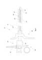
図1は、本発明によるレゼクトスコープ10の断面図を示す。図2は、レゼクトスコープシャフト12の遠位方向からの正面図を示し、図1からのレゼクトスコープ10のシャフト要素のみが示され、ハンドグリップ44の要素は示されていない。レゼクトスコープ10は、通例の形式では、ハンドグリップ44とシャフト12とを備えている。ハンドグリップ44は、レゼクトスコープ10を手に持つため、殊にシャフト12を通って延びる挿通器具を片手で操作するために形成されている。 FIG. 1 shows a cross-sectional view of the
図示されたレゼクトスコープ10は、シャフト12の近位に配置されたグリップ部材46及び48が、ばねブリッジ(Federbruecke)52によって加えられるばね力に抗して相互に相対運動することによって、スライダ50が遠位の第1グリップ部材48に向かって遠位方向に摺動させられる受動的な送り装置を有する。スライダ50をグリップ部材48に向かって遠位方向に摺動させた場合、電極器具20が図示されない仕方で強制案内され、遠位に摺動させられる。ハンドグリップ部材46、48を解放した場合、ばねブリッジ52によって生成されたばね力がスライダ50を静止位置へ強制的に戻し、電極器具20が近位方向に引っ張られる。スライダ50が摺動して戻った場合、電極器具20により手術者の手の力なしに、すなわち受動的に電気外科的手術を行うことができる。 The illustrated
レゼクトスコープ10のシャフト12はシース管14を備え、このシース管の内部には複数の長尺の挿通器具が延び、特に細長い光学系18、電極器具20、及び洗浄管16が延びる。図1及び図2において、洗浄管16の内部にはそれ以外の挿通器具が延びていないことが見て取れる。したがって、シース管14内には洗浄管16の他に、特に電極器具20及び光学系18が配置されている。その場合、安定させるために、電極器具20は保持要素36によって径方向の変位が防止されている。保持要素36は円弧形状の断面を有し、この円弧形状の断面は、ここに示される器具では、シース管14の内壁26に、内壁26の内周の略半分に沿って当接する。したがってこの事例では、保持要素36の断面が、図2に見て取れるように略半円形状である。換言すると、保持要素36は、シース管14の内壁26と部分的に相補的な形状である。それによって、保持要素36は、シース管14の内部を軸方向に摺動可能である一方で、径方向に支持される。 The
保持要素36は、シース管14の内周に沿って、電極器具の2つのフォーク管54、56を互いに接続する。保持要素36と2つのフォーク管54、56との接続は、通例のように、例えばレーザビーム溶接などで作成することができる。これに代えて、フォーク管54、56と保持要素36を一体型に製造することもできる。 The holding
電極器具20は、その遠位端に電極を有し、この事例では電極は、ループ電極42又はカッティングループとして形成されている。器具は、バイポーラ器具として形成され、図示されない対向電極を備えている。ループ電極42によって、医療従事者は、外科手術時に手術箇所から組織を切除することができる。 The
洗浄管16は、凸状に湾曲した区分28と凹状に湾曲した区分30を有する断面を具備し、すなわち、丸みを付けた先端を有する鎌形の断面を有する。凹状に湾曲した区分30、つまり鎌形の内側は、シャフト12の長さにわたって光学系18のシャフトに隣接する。凸状に湾曲した区分28は、シース管14の内壁26に隣接する。このようにすることで、シース管14の利用可能な内部空間が可能な限り省スペース的に利用され、洗浄管16の内部容積が最大にされる。洗浄管16を通して遠位方向に、洗浄液を手術箇所へ導くことができる。汚れた洗浄液の逆流は、シース管14の内部において、そこに配置された挿通器具の他に残った空き空間22、すなわち光学系18、洗浄管16、及び電極器具20の他に残った空間22を通して行われる。 The cleaning
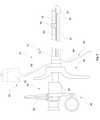
図3及び図4は、図1及び図2に示されたレゼクトスコープの2つの異なった実施形態を示す。図3に示されるレゼクトスコープ10は、上記の要素の他に、洗浄管16の遠位端にノズル32を有する。ノズル32によって、遠位方向に流れる液体流を手術箇所へと誘導することができる。いくつかの実施形態では、ノズル32が液体流を誘導する方向が手動又は自動で調節可能であり得る。このようにして、医療従事者は、手術中に液体流の方向を調整することができ、必要な場合に変更することができる。さらに、ノズル32は、液体流に対して加速するように作用し、それにより洗浄液が直接逆流することが阻止される。 3 and 4 show two different embodiments of the resectoscope shown in FIGS. 1 and 2. The
これに代わる図4に示された実施形態では、洗浄管16は、その遠位端にディフューザ34を有する。遠位方向に流れる液体流をディフューザ34によって誘導し、液体流の速度を低下させることができる。ディフューザ34は、例えば、わずかな出血しか伴わない手術の場合に有用であり得る。液体流を減速させることによって、この実施例による手術は特に保全的になる。 In the alternative embodiment shown in FIG. 4, the
さらに、図4におけるレゼクトスコープ10は、シース管14の先端に電気絶縁要素、セラミック先端として形成された絶縁先端58を有する。このようにしてループ電極42と洗浄管16の遠位端及び他の要素との間の短絡が阻止される。 Further, the
さらには図4に示されるレゼクトスコープ10は、図1~図3に示されるものとは異なる保持要素36を有する電極器具20を具備する。ここに図示される電極器具20は2つの保持要素36を有し、図4に2つのうちの1つのみが見て取れる。保持要素36は、電極器具20をシース管14の内壁26にではなく、光学系18の外壁24に支持する。2つの保持要素36の断面は、同様に円弧形状の断面を有するが、この断面は図2に示される略半円形状の断面より小さい。保持要素36は、光学系18の外壁24に形状相補的に隣接し、残りの電極器具20と一緒に光学系18に対して平行に、すなわち軸方向に摺動可能である。 Further, the
図5は、洗浄液供給装置40を有する本発明による電気外科システムの模式的側断面図を示す。図示された実施形態では、洗浄液供給装置40は、液体リザーバ62と、洗浄液をレゼクトスコープ10の洗浄管16に流入させることができるホース64とを備えている。図示された実施形態では、洗浄液は、液体リザーバ62内の液体の静水圧によって洗浄管に流れ込む。レゼクトスコープ10に相対して液体リザーバ62の高さを変化させることによって、洗浄液の速度を適合させることができる。洗浄液は、手術箇所に達した後、シース管14の内壁26と、その中に配置された挿通器具との間の空間22を通って再び流出することができる。したがって、この事例では洗浄液排出装置60がホース66を備え、液体はこのホースを通って流出することができる。 FIG. 5 shows a schematic side sectional view of an electrosurgical system according to the present invention having a cleaning
本発明は実施例をもとにして詳しく説明されたが、本発明はこれらの実施例に限定されるものでなく、むしろ、添付の特許請求の範囲を逸脱しない範囲で、いくつかの特徴を省略する、又は上記の個々の特徴の別様の組み合わせを実現することができる種々の変更が可能であるということは当業者に自明である。本開示は、上記の個々の特徴のすべての組み合わせを含む。 Although the present invention has been described in detail based on examples, the present invention is not limited to these examples, but rather has some features within the scope of the appended claims. It is self-evident to those skilled in the art that various modifications can be made that can be omitted or that different combinations of the above individual features can be achieved. The present disclosure includes all combinations of the individual features described above.
10 レゼクトスコープ
12 シャフト
14 シース管
16 洗浄管
18 光学系
20 電極器具
22 空間
24 外壁 光学系
26 内壁 シース管
28 凸状に湾曲した区分
30 凹状に湾曲した区分
32 ノズル
34 ディフューザ
36 保持要素
38 電気外科システム
40 洗浄液供給装置
42 ループ電極
44 ハンドグリップ
46 グリップ部材
48 グリップ部材
50 スライダ
52 ばねブリッジ
54 フォーク管
56 フォーク管
58 絶縁先端
60 洗浄液排出装置
62 液体リザーバ
64 ホース
66 ホース10
本発明は、請求項1の前提部に記載の種類のレゼクトスコープ、及び請求項10の前提部に記載の種類の電気外科システムに関する。The present invention relates to a resectoscope of the type according to the premise of claim 1 and an electrosurgical system of the type according to the premise of
上記課題は、請求項1の特徴を有するレゼクトスコープ、及び請求項10の特徴を有する電気外科システムによって解決される。特に、上記課題は、電極器具及びロッド状の光学系を、洗浄液供給のために利用される内管(洗浄管)に対して平行に、すなわち内管の外側に案内することによって解決される。したがって両方の挿通器具(電極器具及び光学系)がもはや内管内に案内されない。このようにすることで渦流の発生が回避される。さらに、外管(シース管)の内部空間の残り全部を、患者の体から汚れた洗浄液を導出するために利用することができる。The above-mentioned problems are solved by a resectoscope having the feature of claim 1 and an electrosurgical system having the feature of
Claims (11)
Translated fromJapaneseApplications Claiming Priority (3)
| Application Number | Priority Date | Filing Date | Title |
|---|---|---|---|
| DE102018129904.4 | 2018-11-27 | ||
| DE102018129904.4ADE102018129904A1 (en) | 2018-11-27 | 2018-11-27 | Resectoscope with an electrode instrument in the outer shaft |
| PCT/EP2019/082476WO2020109257A1 (en) | 2018-11-27 | 2019-11-25 | Resectoscope with electrode instrument in the outer shaft |
Publications (2)
| Publication Number | Publication Date |
|---|---|
| JP2022509229Atrue JP2022509229A (en) | 2022-01-20 |
| JP7194283B2 JP7194283B2 (en) | 2022-12-21 |
Family
ID=68699435
Family Applications (1)
| Application Number | Title | Priority Date | Filing Date |
|---|---|---|---|
| JP2021530213AActiveJP7194283B2 (en) | 2018-11-27 | 2019-11-25 | resectoscope with electrode instrumentation on the outer shaft |
Country Status (6)
| Country | Link |
|---|---|
| US (1) | US12096975B2 (en) |
| EP (1) | EP3886738A1 (en) |
| JP (1) | JP7194283B2 (en) |
| CN (1) | CN113164186A (en) |
| DE (1) | DE102018129904A1 (en) |
| WO (1) | WO2020109257A1 (en) |
Families Citing this family (2)
| Publication number | Priority date | Publication date | Assignee | Title |
|---|---|---|---|---|
| EP3948780A1 (en)* | 2019-03-29 | 2022-02-09 | Howmedica Osteonics Corp. | Pre-morbid characterization of anatomical object using statistical shape modeling (ssm) |
| CN115137473A (en)* | 2022-06-07 | 2022-10-04 | 上海诺英医疗器械有限公司 | Electrode of resectoscope |
Citations (4)
| Publication number | Priority date | Publication date | Assignee | Title |
|---|---|---|---|---|
| JPS58500594A (en)* | 1981-04-10 | 1983-04-21 | ウイドラン,ジエラルド | Continuous flow urinary endoscopy device |
| JPS6143452Y2 (en)* | 1984-01-26 | 1986-12-09 | ||
| US5807240A (en)* | 1996-09-24 | 1998-09-15 | Circon Corporation | Continuous flow endoscope with enlarged outflow channel |
| JP2018519875A (en)* | 2015-05-20 | 2018-07-26 | アーベー メディカ | Device for excising tissue in the body cavity of the body |
Family Cites Families (20)
| Publication number | Priority date | Publication date | Assignee | Title |
|---|---|---|---|---|
| US3850175A (en)* | 1972-07-03 | 1974-11-26 | J Lglesias | Resectoscope with continuous irrigation |
| US3900022A (en)* | 1973-12-10 | 1975-08-19 | Jerrold Widran | Endoscope with uninterrupted flow purging system |
| US4950278A (en)* | 1986-08-06 | 1990-08-21 | Sachse Hans E | Endoscope for removal of tissue |
| US5112330A (en)* | 1988-09-16 | 1992-05-12 | Olympus Optical Co., Ltd. | Resectoscope apparatus |
| US6086584A (en)* | 1998-09-10 | 2000-07-11 | Ethicon, Inc. | Cellular sublimation probe and methods |
| US6358200B1 (en)* | 1999-09-01 | 2002-03-19 | Circon Corporation | Continuous flow resectoscope with single tube sheath assembly and rotatable connection |
| DE10310614B4 (en)* | 2002-03-25 | 2007-10-11 | Richard Wolf Gmbh | resectoscope |
| DE10248836A1 (en)* | 2002-10-19 | 2004-05-06 | Olympus Winter & Ibe Gmbh | Resectoscope with positioned optics |
| US20070270647A1 (en)* | 2006-05-19 | 2007-11-22 | Ams Research Corporation | Handle for Multifunction Endoscope |
| WO2008024290A2 (en)* | 2006-08-19 | 2008-02-28 | Fritsch Michael H | Devices and methods for in-vivo pathology diagnosis |
| US20110160715A1 (en)* | 2009-12-31 | 2011-06-30 | Isaac Ostrovsky | Collapsible irrigation channel for procedures involving fluid circulation |
| WO2011150111A1 (en)* | 2010-05-28 | 2011-12-01 | Gyrus Acmi, Inc. | Continuous flow endoscope system |
| JP5331840B2 (en)* | 2011-02-28 | 2013-10-30 | 富士フイルム株式会社 | Endoscope |
| JP2015159924A (en)* | 2014-02-27 | 2015-09-07 | セイコーエプソン株式会社 | Laparoscopic surgical instrument |
| DE102015003045B4 (en)* | 2015-03-11 | 2024-11-14 | Olympus Winter & Ibe Gmbh | Transporter for a high-frequency resectoscope with electrically contacted spring unit, spring unit and resectoscope |
| EP3340852A2 (en)* | 2015-08-27 | 2018-07-04 | Boston Scientific Scimed Inc. | Medical devices and methods |
| US10383682B2 (en) | 2015-08-28 | 2019-08-20 | Covidien Lp | Powered bipolar resectoscope |
| DE102015014254B4 (en)* | 2015-11-05 | 2019-01-24 | OLYMPUS Winter & lbe GmbH | Medical instrument for endoscopic applications and flushing attachment for an optical unit of a medical instrument for endoscopic applications |
| US11864735B2 (en)* | 2016-05-26 | 2024-01-09 | Covidien Lp | Continuous flow endoscope |
| DE102018114448A1 (en) | 2018-06-15 | 2019-12-19 | Olympus Winter & Ibe Gmbh | Resectoscope with flush-mounted irrigation tube |
- 2018
- 2018-11-27DEDE102018129904.4Apatent/DE102018129904A1/enactivePending
- 2019
- 2019-11-25JPJP2021530213Apatent/JP7194283B2/enactiveActive
- 2019-11-25WOPCT/EP2019/082476patent/WO2020109257A1/ennot_activeCeased
- 2019-11-25CNCN201980077410.7Apatent/CN113164186A/enactivePending
- 2019-11-25USUS17/297,943patent/US12096975B2/enactiveActive
- 2019-11-25EPEP19809793.3Apatent/EP3886738A1/enactivePending
Patent Citations (4)
| Publication number | Priority date | Publication date | Assignee | Title |
|---|---|---|---|---|
| JPS58500594A (en)* | 1981-04-10 | 1983-04-21 | ウイドラン,ジエラルド | Continuous flow urinary endoscopy device |
| JPS6143452Y2 (en)* | 1984-01-26 | 1986-12-09 | ||
| US5807240A (en)* | 1996-09-24 | 1998-09-15 | Circon Corporation | Continuous flow endoscope with enlarged outflow channel |
| JP2018519875A (en)* | 2015-05-20 | 2018-07-26 | アーベー メディカ | Device for excising tissue in the body cavity of the body |
Also Published As
| Publication number | Publication date |
|---|---|
| WO2020109257A4 (en) | 2020-07-23 |
| EP3886738A1 (en) | 2021-10-06 |
| US12096975B2 (en) | 2024-09-24 |
| US20220047321A1 (en) | 2022-02-17 |
| WO2020109257A1 (en) | 2020-06-04 |
| JP7194283B2 (en) | 2022-12-21 |
| CN113164186A (en) | 2021-07-23 |
| DE102018129904A1 (en) | 2020-05-28 |
Similar Documents
| Publication | Publication Date | Title |
|---|---|---|
| JP4290013B2 (en) | Endoscope outflow system | |
| US6500113B2 (en) | Debris aspirating resectoscope | |
| US3835842A (en) | Endoscope with continuous irrigation | |
| US6645140B2 (en) | Continuously rinsing double-sheath endoscope | |
| JP6005630B2 (en) | Continuous flow endoscope system | |
| US5823940A (en) | Optical surgical device for examining genitourinary tissue | |
| US5855549A (en) | Method of using an optical female urethroscope | |
| US9155453B2 (en) | Efficient continuous flow irrigation endoscope | |
| JP7449703B2 (en) | Removable insulation insert for use with resectoscopes | |
| WO1993012732A1 (en) | Endoscopic method and device for subgingival dental procedures | |
| JP7194283B2 (en) | resectoscope with electrode instrumentation on the outer shaft | |
| JP6933653B2 (en) | Resectoscope and electrode assembly for it | |
| JP6483381B2 (en) | Electrode assembly | |
| US6328734B1 (en) | Flexible endoscope with bipolar return electrode and working channel | |
| US20250235262A1 (en) | Devices, systems, and methods for removing materials from a body | |
| US20250235222A1 (en) | Medical devices with passive and active drains | |
| US20240315764A1 (en) | Resectoscope | |
| Levine | Hysteroscopic instruments | |
| CN116965758A (en) | Inter-sheath perfusion type endoscope | |
| CN113598692A (en) | Chamber mirror camera lens washing unit | |
| JP6172743B2 (en) | Endoscope | |
| CN117838298A (en) | Transurethral Vaporization Suction Mirror | |
| PRESS et al. | Endoscope modifications for laser prostatectomy | |
| JP2001204737A (en) | Medical laser apparatus |
Legal Events
| Date | Code | Title | Description |
|---|---|---|---|
| A521 | Request for written amendment filed | Free format text:JAPANESE INTERMEDIATE CODE: A523 Effective date:20210720 | |
| A524 | Written submission of copy of amendment under article 19 pct | Free format text:JAPANESE INTERMEDIATE CODE: A525 Effective date:20210720 | |
| A621 | Written request for application examination | Free format text:JAPANESE INTERMEDIATE CODE: A621 Effective date:20210720 | |
| A977 | Report on retrieval | Free format text:JAPANESE INTERMEDIATE CODE: A971007 Effective date:20220630 | |
| A131 | Notification of reasons for refusal | Free format text:JAPANESE INTERMEDIATE CODE: A131 Effective date:20220715 | |
| A521 | Request for written amendment filed | Free format text:JAPANESE INTERMEDIATE CODE: A523 Effective date:20221006 | |
| TRDD | Decision of grant or rejection written | ||
| A01 | Written decision to grant a patent or to grant a registration (utility model) | Free format text:JAPANESE INTERMEDIATE CODE: A01 Effective date:20221111 | |
| A61 | First payment of annual fees (during grant procedure) | Free format text:JAPANESE INTERMEDIATE CODE: A61 Effective date:20221209 | |
| R150 | Certificate of patent or registration of utility model | Ref document number:7194283 Country of ref document:JP Free format text:JAPANESE INTERMEDIATE CODE: R150 |