JP2022509083A - Eyepieces for augmented reality display systems - Google Patents
Eyepieces for augmented reality display systemsDownload PDFInfo
- Publication number
- JP2022509083A JP2022509083AJP2021527173AJP2021527173AJP2022509083AJP 2022509083 AJP2022509083 AJP 2022509083AJP 2021527173 AJP2021527173 AJP 2021527173AJP 2021527173 AJP2021527173 AJP 2021527173AJP 2022509083 AJP2022509083 AJP 2022509083A
- Authority
- JP
- Japan
- Prior art keywords
- region
- eyepiece waveguide
- cpe
- lattice
- eyepiece
- Prior art date
- Legal status (The legal status is an assumption and is not a legal conclusion. Google has not performed a legal analysis and makes no representation as to the accuracy of the status listed.)
- Pending
Links
Images


Classifications
- G—PHYSICS
- G02—OPTICS
- G02B—OPTICAL ELEMENTS, SYSTEMS OR APPARATUS
- G02B27/00—Optical systems or apparatus not provided for by any of the groups G02B1/00 - G02B26/00, G02B30/00
- G02B27/01—Head-up displays
- G02B27/017—Head mounted
- G02B27/0172—Head mounted characterised by optical features
- G—PHYSICS
- G02—OPTICS
- G02B—OPTICAL ELEMENTS, SYSTEMS OR APPARATUS
- G02B27/00—Optical systems or apparatus not provided for by any of the groups G02B1/00 - G02B26/00, G02B30/00
- G02B27/0081—Optical systems or apparatus not provided for by any of the groups G02B1/00 - G02B26/00, G02B30/00 with means for altering, e.g. enlarging, the entrance or exit pupil
- G—PHYSICS
- G02—OPTICS
- G02B—OPTICAL ELEMENTS, SYSTEMS OR APPARATUS
- G02B27/00—Optical systems or apparatus not provided for by any of the groups G02B1/00 - G02B26/00, G02B30/00
- G02B27/28—Optical systems or apparatus not provided for by any of the groups G02B1/00 - G02B26/00, G02B30/00 for polarising
- G02B27/283—Optical systems or apparatus not provided for by any of the groups G02B1/00 - G02B26/00, G02B30/00 for polarising used for beam splitting or combining
- G—PHYSICS
- G02—OPTICS
- G02B—OPTICAL ELEMENTS, SYSTEMS OR APPARATUS
- G02B27/00—Optical systems or apparatus not provided for by any of the groups G02B1/00 - G02B26/00, G02B30/00
- G02B27/42—Diffraction optics, i.e. systems including a diffractive element being designed for providing a diffractive effect
- G02B27/4205—Diffraction optics, i.e. systems including a diffractive element being designed for providing a diffractive effect having a diffractive optical element [DOE] contributing to image formation, e.g. whereby modulation transfer function MTF or optical aberrations are relevant
- G02B27/4227—Diffraction optics, i.e. systems including a diffractive element being designed for providing a diffractive effect having a diffractive optical element [DOE] contributing to image formation, e.g. whereby modulation transfer function MTF or optical aberrations are relevant in image scanning systems
- G—PHYSICS
- G02—OPTICS
- G02B—OPTICAL ELEMENTS, SYSTEMS OR APPARATUS
- G02B27/00—Optical systems or apparatus not provided for by any of the groups G02B1/00 - G02B26/00, G02B30/00
- G02B27/42—Diffraction optics, i.e. systems including a diffractive element being designed for providing a diffractive effect
- G02B27/4272—Diffraction optics, i.e. systems including a diffractive element being designed for providing a diffractive effect having plural diffractive elements positioned sequentially along the optical path
- G—PHYSICS
- G06—COMPUTING OR CALCULATING; COUNTING
- G06T—IMAGE DATA PROCESSING OR GENERATION, IN GENERAL
- G06T19/00—Manipulating 3D models or images for computer graphics
- G06T19/006—Mixed reality
- G—PHYSICS
- G02—OPTICS
- G02B—OPTICAL ELEMENTS, SYSTEMS OR APPARATUS
- G02B27/00—Optical systems or apparatus not provided for by any of the groups G02B1/00 - G02B26/00, G02B30/00
- G02B27/01—Head-up displays
- G02B27/0101—Head-up displays characterised by optical features
- G02B2027/0118—Head-up displays characterised by optical features comprising devices for improving the contrast of the display / brillance control visibility
- G—PHYSICS
- G02—OPTICS
- G02B—OPTICAL ELEMENTS, SYSTEMS OR APPARATUS
- G02B27/00—Optical systems or apparatus not provided for by any of the groups G02B1/00 - G02B26/00, G02B30/00
- G02B27/01—Head-up displays
- G02B27/0101—Head-up displays characterised by optical features
- G02B2027/0127—Head-up displays characterised by optical features comprising devices increasing the depth of field
Landscapes
- Physics & Mathematics (AREA)
- General Physics & Mathematics (AREA)
- Optics & Photonics (AREA)
- Engineering & Computer Science (AREA)
- Computer Graphics (AREA)
- Computer Hardware Design (AREA)
- General Engineering & Computer Science (AREA)
- Software Systems (AREA)
- Theoretical Computer Science (AREA)
- Diffracting Gratings Or Hologram Optical Elements (AREA)
Abstract
Translated fromJapaneseDescription
Translated fromJapanese(任意の優先権主張に対する参照による組み込み)
本願は、2018年11月20日に出願され、「EYEPIECES FOR AUGMENTED REALITY DISPLAY SYSTEM」と題された、米国仮特許出願62/769,933号の優先権を主張する。それに関して外国または国内の優先権の主張が本願とともに出願されるような出願データシートにおいて識別されている、前述の出願および任意の他の出願は、37CFR1.57下、参照することによって本明細書に組み込まれる。(Incorporation by reference to any priority claim)
This application claims the priority of US Provisional Patent Application No. 62 / 769,933, filed November 20, 2018, entitled "EYEPIECES FOR AUGMENTED REALITY DISPLAY SYSTEM". The aforementioned application and any other application in which a foreign or national priority claim is identified in the application data sheet as filed with this application are herein by reference, under 37CFR 1.57. Will be incorporated into.
本開示は、仮想現実、拡張現実、および複合現実システムのための接眼レンズに関する。 The present disclosure relates to eyepieces for virtual reality, augmented reality, and mixed reality systems.
現代のコンピューティングおよび表示技術は、仮想現実、拡張現実、および複合現実システムの開発を促進している。仮想現実、すなわち、「VR」システムは、ユーザが体験するためのシミュレートされた環境を作成する。これは、頭部搭載型ディスプレイを通して、コンピュータ生成画像データをユーザに提示することによって行われることができる。本画像データは、感覚体験を作成し、これは、ユーザをシミュレートされた環境内に没入させる。仮想現実シナリオは、典型的には、実際の実世界画像データもまた含むのではなく、コンピュータ生成画像データのみの提示を伴う。 Modern computing and display technologies are driving the development of virtual reality, augmented reality, and mixed reality systems. Virtual reality, or "VR" system, creates a simulated environment for the user to experience. This can be done by presenting computer-generated image data to the user through a head-mounted display. The image data creates a sensory experience that immerses the user in a simulated environment. Virtual reality scenarios typically involve the presentation of computer-generated image data only, rather than also including real-world image data.
拡張現実システムは、概して、実世界環境をシミュレートされた要素で補完する。例えば、拡張現実すなわち、「AR」システムは、頭部搭載型ディスプレイを介して、ユーザに、周囲実世界環境のビューを提供し得る。しかしながら、コンピュータ生成画像データもまた、ディスプレイ上に提示され、実世界環境を向上させることができる。本コンピュータ生成画像データは、実世界環境にコンテキスト的に関連する、要素を含むことができる。そのような要素は、シミュレートされたテキスト、画像、オブジェクト等を含むことができる。複合現実または「MR」システムは、あるタイプのARシステムであって、これもシミュレートされたオブジェクトを実世界環境の中に導入するが、これらのオブジェクトは、典型的には、さらなる相互作用の程度を特徴とする。シミュレートされた要素は、多くの場合、リアルタイムで双方向性であることができる。 Augmented reality systems generally complement the real-world environment with simulated elements. For example, augmented reality or an "AR" system may provide the user with a view of the surrounding real world environment via a head-mounted display. However, computer-generated image data can also be presented on the display to improve the real-world environment. The computer-generated image data may include elements that are contextually relevant to the real world environment. Such elements can include simulated text, images, objects, and the like. A mixed reality or "MR" system is a type of AR system that also introduces simulated objects into a real-world environment, but these objects are typically of further interaction. Characterized by degree. Simulated elements can often be bidirectional in real time.
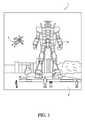
図1は、例示的AR場面1を描写し、ユーザには、人々、木々、背景における建物、およびコンクリートプラットフォーム20を特徴とする、実世界公園設定6が見える。これらのアイテムに加え、コンピュータ生成画像データもまた、ユーザに提示される。コンピュータ生成画像データは、例えば、実世界プラットフォーム20上に立っているロボット像10と、マルハナバチの擬人化のように見える、飛んでいる漫画のようなアバタキャラクタ2とを含むことができるが、これらの要素2、10は、実際には、実世界環境内に存在しない。 FIG. 1 depicts an
いくつかの実施形態では、拡張現実ディスプレイシステムのための接眼レンズ導波管は、第1の表面および第2の表面を有する、光学的に透過性の基板と、基板の表面のうちの1つ上または該1つ内に形成される、入力結合格子(ICG)領域であって、光の入力ビームを受け取り、誘導ビームとして、入力ビームを基板の中に結合するように構成される、ICG領域と、基板の第1の表面上または該第1の表面内に形成される、第1の組み合わせられた瞳エクスパンダ-抽出器(CPE)格子領域であって、誘導ビームをICG領域から受け取り、第1の複数の回折ビームを複数の分散された場所に作成し、第1の複数の出力ビームを外部結合するように位置付けられる、第1のCPE格子領域と、基板の第2の表面上または該第2の表面内に形成される、第2のCPE格子領域であって、誘導ビームをICG領域から受け取り、第2の複数の回折ビームを複数の分散された場所に作成し、第2の複数の出力ビームを外部結合するように位置付けられる、第2のCPE格子領域とを備える。 In some embodiments, the eyepiece waveguide for an augmented reality display system is an optically transmissive substrate having a first surface and a second surface, and one of the surfaces of the substrate. An input coupling lattice (ICG) region formed above or within the one, which is configured to receive an input beam of light and couple the input beam into a substrate as a guided beam. And a first combined pupil expander-extractor (CPE) lattice region formed on or within the first surface of the substrate, receiving the guided beam from the ICG region. A first CPE grid region and a second surface of the substrate or located to externally couple the first plurality of output beams to create the first plurality of diffracted beams in multiple dispersed locations. A second CPE lattice region formed within the second surface, the guided beam is received from the ICG region, and a second plurality of diffracted beams are created in a plurality of dispersed locations to create a second. It includes a second CPE grid region that is positioned to externally couple the plurality of output beams.
いくつかの実施形態では、拡張現実ディスプレイシステムのための接眼レンズ導波管は、光学的に透過性の基板と、入力結合格子(ICG)領域と、第1の組み合わせられた瞳エクスパンダ-抽出器(CPE)格子領域と、第2のCPE格子領域とを備え、ICG領域は、複数の光の入力ビームのセットを受け取るように構成され、入力ビームのセットは、接眼レンズ導波管と関連付けられるk-空間環の中心に位置する視野(FOV)形状を形成する、k-ベクトルのセットと関連付けられ、ICG領域は、誘導ビームとして、それらを基板の中に結合するように、かつ少なくとも部分的に、k-空間環内において、FOV形状を第1の位置に平行移動させるように、入力ビームを回折するように構成され、第1のCPE格子領域は、少なくとも部分的に、k-空間環内において、FOV形状を第1の位置から第2の位置に平行移動させるように、誘導ビームを回折するように構成され、第2のCPE格子領域は、少なくとも部分的に、k-空間環内において、FOV形状を第1の位置から第3の位置に平行移動させるように、誘導ビームを回折するように構成され、第1のCPE格子領域は、FOV形状を第3の位置からk-空間環の中心に平行移動させるように、誘導ビームを回折するように構成され、第2のCPE格子領域は、FOV形状を第2の位置からk-空間環の中心に平行移動させるように、誘導ビームを回折するように構成される。 In some embodiments, the eyepiece waveguide for the augmented reality display system is an optically transmissive substrate, an input coupled lattice (ICG) region, and a first combined pupil expander extraction. It comprises a vessel (CPE) lattice region and a second CPE lattice region, the ICG region is configured to receive a set of input beams of multiple light, and the set of input beams is associated with an eyepiece lens waveguide. Associated with a set of k-vectors that form a field of view (FOV) shape located in the center of the k-spatial ring, the ICG region, as a guided beam, couples them into the substrate and at least partially. The first CPE lattice region is configured to diffract the input beam so as to move the FOV shape in parallel to the first position within the k-space ring, and the first CPE lattice region is at least partially k-space. Within the ring, the guided beam is configured to diffract the guided beam so that the FOV shape moves parallel from the first position to the second position, and the second CPE lattice region is at least partially a k-spatial ring. Within, the FOV shape is configured to diffract the guided beam so as to move the FOV shape in parallel from the first position to the third position, and the first CPE lattice region is a k- that moves the FOV shape from the third position. The second CPE lattice region is configured to diffract the guided beam so as to move parallel to the center of the space ring, and the second CPE lattice region moves the FOV shape parallel to the center of the k-space ring from the second position. It is configured to diffract the induced beam.
いくつかの実施形態では、拡張現実ディスプレイシステムのための接眼レンズ導波管は、第1の表面および第2の表面を有する、光学的に透過性の基板と、基板の表面のうちの1つ上または該1つ内に形成される、入力結合格子(ICG)領域であって、光のビームを受け取り、誘導伝搬モードにおいて、ビームを基板の中に結合するように構成される、ICG領域と、基板の第1の表面上または該第1の表面内に形成される、第1の組み合わせられた瞳エクスパンダ-抽出器(CPE)格子領域であって、第1のCPE格子領域は、ICG領域からの光のビームを受け取るように位置付けられ、第1の相互作用を用いて、ビームの伝搬方向を改変し、第2の相互作用を用いて、ビームを接眼レンズ導波管から外部結合するように構成される、複数の回折特徴を備える、第1のCPE格子領域とを備える。 In some embodiments, the eyepiece waveguide for an augmented reality display system is an optically transmissive substrate having a first surface and a second surface, and one of the surfaces of the substrate. An input coupling lattice (ICG) region formed above or within the one that receives a beam of light and is configured to couple the beam into a substrate in guided propagation mode. , A first combined pupil expander-extractor (CPE) lattice region formed on or within the first surface of the substrate, wherein the first CPE lattice region is an ICG. Positioned to receive a beam of light from the region, the first interaction is used to modify the direction of propagation of the beam, and the second interaction is used to externally couple the beam from the eyepiece waveguide. It comprises a first CPE lattice region with a plurality of diffraction features configured as such.
いくつかの実施形態では、拡張現実ディスプレイシステムのための接眼レンズ導波管は、光学的に透過性の基板と、入力結合格子(ICG)領域と、基板の第1の側上に形成される、第1の組み合わせられた瞳エクスパンダ-抽出器(CPE)格子領域とを備え、ICG領域は、複数の光の入力ビームのセットを受け取るように構成され、入力ビームのセットは、接眼レンズ導波管と関連付けられるk-空間環の中心に位置する視野(FOV)形状を形成する、k-ベクトルのセットと関連付けられ、ICG領域は、誘導ビームとして、それらを基板の中に結合するように、かつ少なくとも部分的に、k-空間環内において、FOV形状を第1の位置に平行移動させるように、入力ビームを回折するように構成され、第1の相互作用を用いて、第1のCPE格子領域は、少なくとも部分的に、k-空間環内において、FOV形状を第1の位置から第2および第3の位置に平行移動させるように、誘導ビームを回折するように構成され、第2の相互作用を用いて、第1のCPE格子領域は、FOV形状を第2および第3の位置からk-空間環の中心に平行移動させるように、誘導ビームを回折するように構成される。 In some embodiments, the eyepiece waveguide for the augmented reality display system is formed on an optically transmissive substrate, an input coupling lattice (ICG) region, and a first side of the substrate. A first combined pupil expander-extractor (CPE) lattice region is provided, the ICG region is configured to receive a set of input beams of multiple light, and the set of input beams is an eyepiece guide. Associated with a set of k-vectors that form a field (FOV) shape located in the center of the k-spatial ring associated with the wave tube, the ICG region as a guided beam couples them into the substrate. And at least in part, it is configured to diffract the input beam so as to translate the FOV shape into the first position within the k-spatial ring, and using the first interaction, the first. The CPE lattice region is configured to diffract the guided beam so as to translate the FOV shape from the first position to the second and third positions, at least in part, within the k-spatial ring. Using the interaction of 2, the first CPE lattice region is configured to diffract the guided beam so that the FOV shape is translated from the second and third positions to the center of the k-spatial ring. ..
概要
本開示は、画像をユーザの眼に投影するためにARディスプレイシステム内で使用され得る、種々の接眼レンズ導波管を説明する。接眼レンズ導波管は、物理的用語およびk-空間表現の使用の両方において説明される。Summary The present disclosure describes various eyepiece waveguides that can be used within an AR display system to project an image onto the user's eye. Eyepiece waveguides are described in both physical terms and the use of k-space representations.
(例示的HMDデバイス)
図2は、ウェアラブルディスプレイシステム60の実施例を図示する。ディスプレイシステム60は、ディスプレイまたは接眼レンズ70と、そのディスプレイ70の機能をサポートするための種々の機械的および電子モジュールおよびシステムとを含む。ディスプレイ70は、フレーム80に結合されてもよく、これは、ディスプレイシステムユーザ90によって装着可能であって、ディスプレイ70をユーザ90の眼の正面に位置付けるように構成される。ディスプレイ70は、いくつかの実施形態では、アイウェアと見なされてもよい。いくつかの実施形態では、スピーカ100が、フレーム80に結合され、ユーザ90の外耳道に隣接して位置付けられる。ディスプレイシステムはまた、1つ以上のマイクロホン110を含み、音を検出してもよい。マイクロホン110は、ユーザが、入力またはコマンドをシステム60に提供することを可能にすることができ(例えば、音声メニューコマンドの選択、自然言語質問等)、および/または他の人物(例えば、類似ディスプレイシステムの他のユーザ)とのオーディオ通信を可能にすることができる。マイクロホン110はまた、オーディオデータ(例えば、ユーザおよび/または環境からの音)をユーザの周囲から収集することができる。いくつかの実施形態では、ディスプレイシステムもまた、周辺センサ120aを含んでもよく、これは、フレーム80と別個であって、ユーザ90の身体(例えば、頭部、胴体、四肢等上)に取り付けられてもよい。周辺センサ120aは、いくつかの実施形態では、ユーザ90の生理学的状態を特徴付けるデータを取得してもよい。(Exemplary HMD device)
FIG. 2 illustrates an embodiment of a wearable display system 60. The display system 60 includes a display or
ディスプレイ70は、有線導線または無線コネクティビティ等の通信リンク130によって、ローカルデータ処理モジュール140に動作可能に結合され、これは、フレーム80に固定して取り付けられる、ユーザによって装着されるヘルメットまたは帽子に固定して取り付けられる、ヘッドホンに内蔵される、またはユーザ90に除去可能に取り付けられる(例えば、リュック式構成において、またはベルト結合式構成において)等、種々の構成で搭載され得る。同様に、センサ120aは、通信リンク120b(例えば、有線導線または無線コネクティビティ)によって、ローカルプロセッサおよびデータモジュール140に動作可能に結合されてもよい。ローカル処理およびデータモジュール140は、ハードウェアプロセッサおよび不揮発性メモリ(例えば、フラッシュメモリまたはハードディスクドライブ)等のデジタルメモリを含んでもよく、その両方とも、データの処理、キャッシュ、および記憶を補助するために利用され得る。データは、1)画像捕捉デバイス(例えば、カメラ)、マイクロホン、慣性測定ユニット、加速度計、コンパス、GPSユニット、無線デバイス、ジャイロスコープ、および/または本明細書に開示される他のセンサ等の(例えば、フレーム80に動作可能に結合される、または別様にユーザ90に取り付けられ得る)センサから捕捉されるデータ、および/または2)可能性として、処理または読出後にディスプレイ70への通過のために、遠隔処理モジュール150および/または遠隔データリポジトリ160(仮想コンテンツに関連するデータを含む)を使用して入手および/または処理されたデータを含んでもよい。ローカル処理およびデータモジュール140は、これらの遠隔モジュール150、160が相互に動作可能に結合され、ローカル処理およびデータモジュール140に対するリソースとして利用可能であるように、有線または無線通信リンク等を介して、通信リンク170、180によって、遠隔処理モジュール150および遠隔データリポジトリ160に動作可能に結合されてもよい。いくつかの実施形態では、ローカル処理およびデータモジュール140は、画像捕捉デバイス、マイクロホン、慣性測定ユニット、加速度計、コンパス、GPSユニット、無線デバイス、および/またはジャイロスコープのうちの1つ以上のものを含んでもよい。いくつかの他の実施形態では、これらのセンサのうちの1つ以上のものは、フレーム80に取り付けられてもよい、または有線または無線通信経路によってローカル処理およびデータモジュール140と通信する、独立デバイスであってもよい。 The
遠隔処理モジュール150は、画像およびオーディオ情報等のデータを分析および処理するための1つ以上のプロセッサを含んでもよい。いくつかの実施形態では、遠隔データリポジトリ160は、デジタルデータ記憶設備であり得、これは、インターネットまたは「クラウド」リソース構成における他のネットワーキング構成を通して利用可能であってもよい。いくつかの実施形態では、遠隔データリポジトリ160は、情報(例えば、拡張現実コンテンツを生成するための情報)をローカル処理およびデータモジュール140および/または遠隔処理モジュール150に提供する、1つ以上の遠隔サーバを含んでもよい。他の実施形態では、全てのデータが、記憶され、全ての算出が、ローカル処理およびデータモジュールにおいて実施され、遠隔モジュールからの完全に自律的な使用を可能にする。 The
「3次元」または「3-D」としての画像の知覚は、ユーザの各眼への画像の若干異なる提示を提供することによって達成され得る。図3は、ユーザに関する3次元画像データをシミュレートするための従来のディスプレイシステムを図示する。眼210、220毎に1つの2つの明確に異なる画像190、200が、ユーザに出力される。画像190、200は、ユーザの視線と平行な光学またはz-軸に沿って距離230だけ眼210、220から離間される。画像190、200は、平坦であって、眼210、220は、単一の遠近調節された状態をとることによって、画像上に合焦し得る。そのような3-Dディスプレイシステムは、ヒト視覚系に依拠し、画像190、200を組み合わせ、組み合わせられた画像の深度および/または尺度の知覚を提供する。 Perception of an image as "three-dimensional" or "3-D" can be achieved by providing a slightly different presentation of the image to each eye of the user. FIG. 3 illustrates a conventional display system for simulating 3D image data about a user. Two distinctly
しかしながら、ヒト視覚系は、複雑であって、深度の現実的知覚を提供することは、困難である。例えば、従来の「3-D」ディスプレイシステムの多くのユーザは、そのようなシステムが不快であることを見出す、または深度の感覚を全く知覚しない場合がある。オブジェクトは、輻輳・開散運動(vergence)と遠近調節(accommodation)の組み合わせに起因して、「3次元」として知覚され得る。相互に対する2つの眼の輻輳・開散運動の移動(例えば、瞳孔が、相互に向かって、またはそこから離れるように移動し、眼の個別の視線を収束させ、オブジェクトを固視するような瞳孔の回転)は、眼の水晶体の合焦(または「遠近調節」)と緊密に関連付けられる。通常条件下、焦点を1つのオブジェクトから異なる距離における別のオブジェクトに変化させるための眼の水晶体の焦点の変化または眼の遠近調節は、「遠近調節-輻輳・開散運動反射」および散瞳または縮瞳として知られる関係下、輻輳・開散運動の整合変化を自動的に同一距離に生じさせるであろう。同様に、通常条件下、輻輳・開散運動の変化は、水晶体形状および瞳孔サイズの遠近調節の整合変化を誘起するであろう。本明細書に記載されるように、多くの立体視または「3-D」ディスプレイシステムは、3次元視点がヒト視覚系によって知覚されるように、各眼への若干異なる提示(したがって、若干異なる画像)を使用して、場面を表示する。しかしながら、そのようなシステムは、単に、画像情報を単一の遠近調節された状態において提供し、「遠近調節-輻輳・開散運動反射」に対抗して機能するため、一部のユーザにとって不快であり得る。遠近調節と輻輳・開散運動との間のより良好な合致を提供するディスプレイシステムが3次元画像データのより現実的かつ快適なシミュレーションを形成し得る。 However, the human visual system is complex and it is difficult to provide a realistic perception of depth. For example, many users of conventional "3-D" display systems may find such systems uncomfortable or may not perceive a sense of depth at all. Objects can be perceived as "three-dimensional" due to the combination of convergence and accommodation. Movement of the convergence and divergence movements of the two eyes relative to each other (eg, the pupils move toward or away from each other, converging the individual eyes of the eye and staring at the object. Rotation) is closely associated with focusing (or "accommodation") of the crystalline lens of the eye. Under normal conditions, changes in the focal point of the crystalline lens of the eye or accommodation of the eye to change the focus from one object to another at different distances are "accommodation-accommodation / divergent motion reflex" and mydriasis or Under the relationship known as miosis, it will automatically cause a consistent change in converging / divergent motion at the same distance. Similarly, under normal conditions, changes in convergence and divergence movements will induce matching changes in lens shape and accommodation of pupil size. As described herein, many stereoscopic or "3-D" display systems present slightly different (and therefore slightly different) presentations to each eye so that the 3D viewpoint is perceived by the human visual system. Image) is used to display the scene. However, such systems are uncomfortable for some users because they simply provide the image information in a single perspective-adjusted state and work against the "accommodation-convergence / divergent motion reflex". Can be. A display system that provides a better match between accommodation and convergence / divergence motion can form a more realistic and comfortable simulation of 3D image data.
図4は、複数の深度平面を使用して3次元画像データをシミュレートするためのアプローチの側面を図示する。図4を参照すると、眼210、220は、異なる遠近調節された状態をとり、オブジェクトをz-軸に沿って種々の距離に合焦させる。その結果、特定の遠近調節された状態は、特定の深度平面におけるオブジェクトまたはオブジェクトの一部が、眼がその深度平面に対して遠近調節された状態にあるときに合焦するように、関連付けられた焦点距離を有する、図示される深度平面240のうちの特定の1つと関連付けられると言え得る。いくつかの実施形態では、3次元画像データが、眼210、220毎に、画像の異なる提示を提供することによって、また、複数の深度平面に対応する画像の異なる提示を提供することによってシミュレートされてもよい。例証を明確にするために別個であるものとして示されるが、眼210、220の個別の視野は、例えば、z-軸に沿った距離が増加するにつれて、重複し得る。加えて、深度平面は、例証を容易にするために平坦であるものとして示されるが、深度平面の輪郭は、深度平面内の全ての特徴が特定の遠近調節された状態における眼と合焦するように、物理的空間内で湾曲され得ることを理解されたい。 FIG. 4 illustrates aspects of an approach for simulating 3D image data using multiple depth planes. Referring to FIG. 4, the
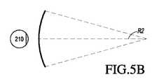
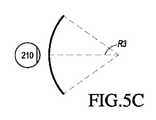
オブジェクトと眼210または220との間の距離はまた、その眼によって視認されるようなそのオブジェクトからの光の発散の量を変化させ得る。図5A-5Cは、距離と光線の発散との間の関係を図示する。オブジェクトと眼210との間の距離は、減少距離R1、R2、およびR3の順序で表される。図5A-5Cに示されるように、光線は、オブジェクトまでの距離が減少するにつれてより発散する。距離が増加するにつれて、光線は、よりコリメートされる。換言すると、点(オブジェクトまたはオブジェクトの一部)によって生成されるライトフィールドは、点がユーザの眼から離れている距離の関数である、球状波面曲率を有すると言え得る。曲率は、オブジェクトと眼210との間の距離の減少に伴って増加する。その結果、異なる深度平面では、光線の発散度もまた、異なり、発散度は、深度平面とユーザの眼210との間の距離の減少に伴って増加する。単眼210のみが、例証を明確にするために、図5A-5Cおよび本明細書の他の図に図示されるが、眼210に関する議論は、ユーザの両眼210および220に適用され得ることを理解されたい。 The distance between an object and the
知覚された深度の高度に真実味のあるシミュレーションが、眼に限定数の深度平面のそれぞれに対応する画像の異なる提示を提供することによって達成され得る。異なる提示は、ユーザの眼によって別個に集束され、それによって、異なる深度平面上に位置する場面のための異なる画像特徴に合焦させるために要求される眼の遠近調節の量に基づいて、および/または焦点がずれている異なる深度平面上の異なる画像特徴の観察に基づいて、ユーザに深度キューを提供することに役立ててもよい。 A highly authentic simulation of the perceived depth can be achieved by providing the eye with different presentations of images corresponding to each of a limited number of depth planes. The different presentations are focused separately by the user's eye, thereby based on the amount of accommodation required to focus on different image features for scenes located on different depth planes, and. / Or may help provide a depth queue to the user based on the observation of different image features on different out-of-focus depth planes.
(ARまたはMR接眼レンズのための導波管スタックアセンブリの実施例)
図6は、AR接眼レンズ内で画像情報をユーザに出力するための導波管スタックの実施例を図示する。ディスプレイシステム250は、複数の導波管270、280、290、300、310を使用して、3次元知覚を眼/脳に提供するために利用され得る、導波管のスタックまたはスタックされた導波管アセンブリ260を含む。いくつかの実施形態では、ディスプレイシステム250は、図2のシステム60であって、図6は、そのシステム60のいくつかの部分をより詳細に図式的に示す。例えば、導波管アセンブリ260は、図2のディスプレイ70の一部であってもよい。ディスプレイシステム250は、いくつかの実施形態では、ライトフィールドディスプレイと見なされてもよいことを理解されたい。(Examples of Waveguide Stack Assembly for AR or MR Eyepieces)
FIG. 6 illustrates an example of a waveguide stack for outputting image information to a user in an AR eyepiece. The
導波管アセンブリ260はまた、複数の特徴320、330、340、350を導波管の間に含んでもよい。いくつかの実施形態では、特徴320、330、340、350は、1つ以上のレンズであってもよい。導波管270、280、290、300、310および/または複数のレンズ320、330、340、350は、種々のレベルの波面曲率または光線発散を用いて、画像情報を眼に送信するように構成されてもよい。各導波管レベルは、特定の深度平面と関連付けられてもよく、その深度平面に対応する画像情報を出力するように構成されてもよい。画像投入デバイス360、370、380、390、400は、導波管のための光源として機能してもよく、画像情報を導波管270、280、290、300、310の中に投入するために利用されてもよく、それぞれ、本明細書に説明されるように、眼210に向かって出力するために、各個別の導波管を横断して入射光を分散させるように構成されてもよい。光は、各個別の画像投入デバイス360、370、380、390、400の出力表面410、420、430、440、450から出射し、個別の導波管270、280、290、300、310の対応する入力表面460、470、480、490、500の中に投入される。いくつかの実施形態では、入力表面460、470、480、490、500はそれぞれ、対応する導波管の縁であってもよい、または対応する導波管の主要表面の一部(すなわち、世界510またはユーザの眼210に直接面する導波管表面のうちの1つ)であってもよい。いくつかの実施形態では、光のビーム(例えば、コリメートされたビーム)が、各導波管の中に投入されてもよく、導波管内の屈折によって、ビームレットにサンプリングすること等によって複製され、次いで、その特定の導波管と関連付けられた深度平面に対応する屈折力の量を伴って、眼210に向かって指向されてもよい。いくつかの実施形態では、画像投入デバイス360、370、380、390、400のうちの単一の1つは、複数(例えば、3つ)の導波管270、280、290、300、310と関連付けられ、その中に光を投入してもよい。 The
いくつかの実施形態では、画像投入デバイス360、370、380、390、400はそれぞれ、対応する導波管270、280、290、300、310の中への投入のための画像情報をそれぞれ生成する、離散ディスプレイである。いくつかの他の実施形態では、画像投入デバイス360、370、380、390、400は、1つ以上の光学導管(光ファイバケーブル等)を介して、画像情報を画像投入デバイス360、370、380、390、400のそれぞれに送り得る、単一の多重化されたディスプレイの出力端である。画像投入デバイス360、370、380、390、400によって提供される画像情報は、異なる波長または色の光を含んでもよいことを理解されたい。 In some embodiments, the
いくつかの実施形態では、導波管270、280、290、300、310の中に投入される光は、光プロジェクタシステム520によって提供され、これは、光モジュール530を含み、これは、発光ダイオード(LED)等の光源または光エミッタを含んでもよい。光モジュール530からの光は、ビームスプリッタ(BS)550を介して、光変調器540(例えば、空間光変調器)によって指向および変調されてもよい。光変調器540は、導波管270、280、290、300、310の中に投入される光の知覚される強度を空間的および/または時間的に変化させてもよい。空間光変調器の実施例は、シリコン上液晶(LCOS)ディスプレイを含む、液晶ディスプレイ(LCD)およびデジタル光処理(DLP)ディスプレイを含む。 In some embodiments, the light emitted into the
いくつかの実施形態では、光プロジェクタシステム520またはその1つ以上のコンポーネントは、フレーム80(図2)に取り付けられてもよい。例えば、光プロジェクタシステム520は、フレーム80のつる部分(例えば、耳掛け部82)の一部である、またはディスプレイ70の縁に配置されてもよい。いくつかの実施形態では、光モジュール530は、BS550および/または光変調器540と別個であってもよい。 In some embodiments, the
いくつかの実施形態では、ディスプレイシステム250は、光を種々のパターン(例えば、ラスタ走査、螺旋走査、リサジューパターン等)で1つ以上の導波管270、280、290、300、310の中に、最終的には、ユーザの眼210の中に投影するための1つ以上の走査ファイバを備える、走査ファイバディスプレイであってもよい。いくつかの実施形態では、図示される画像投入デバイス360、370、380、390、400は、光を1つまたは複数の導波管270、280、290、300、310の中に投入するように構成される、単一走査ファイバまたは走査ファイバの束を図式的に表し得る。いくつかの他の実施形態では、図示される画像投入デバイス360、370、380、390、400は、複数の走査ファイバまたは走査ファイバの複数の束を図式的に表し得、それぞれ、光を導波管270、280、290、300、310のうちの関連付けられた1つの中に投入するように構成される。1つ以上の光ファイバは、光を光モジュール530から1つ以上の導波管270、280、290、300、および310に伝送してもよい。加えて、1つ以上の介在光学構造が、走査ファイバまたは複数のファイバと、1つ以上の導波管270、280、290、300、310との間に提供され、例えば、走査ファイバから出射する光を1つ以上の導波管270、280、290、300、310の中に再指向してもよい。 In some embodiments, the
コントローラ560は、画像投入デバイス360、370、380、390、400、光源530、および光モジュール540の動作を含む、スタックされた導波管アセンブリ260の動作を制御する。いくつかの実施形態では、コントローラ560は、ローカルデータ処理モジュール140の一部である。コントローラ560は、導波管270、280、290、300、310への画像情報のタイミングおよび提供を調整する、プログラミング(例えば、非一過性媒体内の命令)を含む。いくつかの実施形態では、コントローラは、単一一体型デバイスまたは有線または無線通信チャネルによって接続される分散型システムであってもよい。コントローラ560は、いくつかの実施形態では、処理モジュール140または150(図2)の一部であってもよい。 The
導波管270、280、290、300、310は、全内部反射(TIR)によって、各個別の導波管内で光を伝搬するように構成されてもよい。導波管270、280、290、300、310はそれぞれ、主要上部表面および主要底部表面およびそれらの主要上部表面と主要底部表面との間に延在する縁を伴う、平面である、または別の形状(例えば、湾曲)を有してもよい。図示される構成では、導波管270、280、290、300、310はそれぞれ、各個別の導波管内で伝搬する光を導波管から外に再指向し、画像情報を眼210に出力することによって、光を導波管から抽出するように構成される、外部結合光学要素570、580、590、600、610を含んでもよい。抽出された光はまた、外部結合光と称され得、光を外部結合する光学要素はまた、光抽出光学要素と称され得る。抽出された光のビームは、導波管によって、導波管内で伝搬する光が光抽出光学要素に衝打する場所において出力され得る。外部結合光学要素570、580、590、600、610は、例えば、本明細書にさらに議論されるような回折格子を含む、回折光学特徴であってもよい。外部結合光学要素570、580、590、600、610は、導波管270、280、290、300、310の底部主要表面に配置されて図示されるが、いくつかの実施形態では、それらは、本明細書にさらに議論されるように、上部主要表面および/または底部主要表面に配置されてもよく、および/または導波管270、280、290、300、310の容積内に直接配置されてもよい。いくつかの実施形態では、外部結合光学要素570、580、590、600、610は、透明基板に取り付けられ、導波管270、280、290、300、310を形成する、材料の層内に形成されてもよい。いくつかの他の実施形態では、導波管270、280、290、300、310は、材料のモノリシック片であってもよく、外部結合光学要素570、580、590、600、610は、その材料片の表面上および/または内部に形成されてもよい。 The
各導波管270、280、290、300、310は、光を出力し、特定の深度平面に対応する画像を形成してもよい。例えば、眼の最近傍の導波管270は、眼210にコリメートされた光のビームを送達してもよい。コリメートされた光のビームは、光学無限遠焦点面を表し得る。次の上方の導波管280は、眼210に到達する前に、第1のレンズ350(例えば、負のレンズ)を通して通過する、コリメートされた光のビームを出力してもよい。第1のレンズ350は、眼/脳が、その導波管280から生じる光を光学無限遠から眼210に向かって内向きにより近い第1の焦点面から生じるものとして解釈するように、若干の凸面波面曲率をコリメートされたビームに追加してもよい。同様に、第3の上方の導波管290は、眼210に到達する前に、その出力光を第1のレンズ350および第2の340レンズの両方を通して通過させる。第1のレンズ350および第2の340レンズの組み合わせられた屈折力は、眼/脳が、第3の導波管290から生じる光が第2の導波管280からの光であったよりも光学無限遠から内向きにさらに近い第2の焦点面から生じるものとして解釈するように、別の漸増量の波面曲率を追加してもよい。 Each
他の導波管層300、310およびレンズ330、320も同様に構成され、スタック内の最高導波管310が、人物に最も近い焦点面を表す集約焦点力のために、その出力をそれと眼との間のレンズの全てを通して送出する。スタックされた導波管アセンブリ260の他側の世界510から生じる光を視認/解釈するとき、レンズ320、330、340、350のスタックを補償するために、補償レンズ層620が、スタックの上部に配置され、下方のレンズスタック320、330、340、350の集約屈折力を補償してもよい。そのような構成は、利用可能な導波管/レンズ対と同じ数の知覚される焦点面を提供する。導波管の外部結合光学要素およびレンズの集束側面の両方とも、静的であってもよい(すなわち、動的または電気活性ではない)。いくつかの代替実施形態では、一方または両方とも、電気活性特徴を使用して動的であってもよい。 The
いくつかの実施形態では、導波管270、280、290、300、310のうちの2つ以上のものは、同一の関連付けられた深度平面を有してもよい。例えば、複数の導波管270、280、290、300、310が、同一深度平面に設定される画像を出力してもよい、または導波管270、280、290、300、310の複数のサブセットが、深度平面毎に1つのセットを伴う、同一の複数の深度平面に設定される画像を出力してもよい。これは、それらの深度平面において拡張された視野を提供するようにタイル化された画像を形成する利点を提供し得る。 In some embodiments, two or more of the
外部結合光学要素570、580、590、600、610は、導波管と関連付けられる特定の深度平面のために、光をそれらの個別の導波管から再指向し、かつ本光を適切な量の発散またはコリメーションを伴って出力するように構成されてもよい。その結果、異なる関連付けられる深度平面を有する導波管は、関連付けられる深度平面に応じて、異なる量の発散を伴って光を出力する、異なる構成の外部結合光学要素570、580、590、600、610を有してもよい。いくつかの実施形態では、光抽出光学要素570、580、590、600、610は、光を具体的角度で出力するように構成され得る、立体または表面特徴であってもよい。例えば、光抽出光学要素570、580、590、600、610は、立体ホログラム、表面ホログラム、および/または回折格子であってもよい。いくつかの実施形態では、特徴320、330、340、350は、レンズではなくてもよい。むしろ、それらは、単に、スペーサであってもよい(例えば、空隙を形成するためのクラッディング層および/または構造)。 Externally coupled
いくつかの実施形態では、外部結合光学要素570、580、590、600、610は、ビーム内の光の屈折力の一部のみが、各相互作用を伴って、眼210に向かって再指向される一方、残りが、TIRを介して、導波管を通して移動し続けるように、十分に低い回折効率を伴う、回折特徴である。故に、光モジュール530の射出瞳は、導波管を横断して複製され、光源530からの画像情報を搬送する複数の出力ビームを作成し、眼210が複製された光源射出瞳を捉え得る場所の数を効果的に拡張させる。これらの回折特徴はまた、その幾何学形状を横断して可変回折効率を有し、導波管によって出力される光の均一性を改良してもよい。 In some embodiments, the externally coupled
いくつかの実施形態では、1つ以上の回折特徴は、それらが能動的に回折する「オン」状態と有意に回折しない「オフ」状態との間で切替可能であり得る。例えば、切替可能な回折要素は、微小液滴がホスト媒体内に回折パターンを形成する、ポリマー分散液晶の層を備えてもよく、微小液滴の屈折率は、ホスト材料の屈折率に実質的に合致するように切り替えられてもよい(その場合、パターンは、入射光を著しく回折させない)、または微小液滴は、ホスト媒体のものに合致しない屈折率に切り替えられてもよい(その場合、パターンは、入射光を能動的に回折させる)。 In some embodiments, one or more diffraction features may be switchable between an "on" state in which they actively diffract and an "off" state in which they do not diffract significantly. For example, the switchable diffractive element may include a layer of polymer dispersed liquid crystal in which the microdroplets form a diffraction pattern in the host medium, the refraction of the microdroplets being substantially the refraction of the host material. May be switched to match (in which case the pattern does not significantly diffract the incident light), or the microdroplets may be switched to a refractive index that does not match that of the host medium (in which case). The pattern actively diffracts the incident light).
いくつかの実施形態では、カメラアセンブリ630(例えば、可視光およびIR光カメラを含む、デジタルカメラ)が、提供され、眼210、眼210の一部、または眼210を囲繞する組織の少なくとも一部の画像を捕捉し、例えば、ユーザ入力を検出し、バイオメトリック情報を眼から抽出し、眼の視線方向を推定および追跡し、ユーザの生理学的状態を監視すること等を行ってもよい。いくつかの実施形態では、カメラアセンブリ630は、画像捕捉デバイスと、光(例えば、IRまたは近IR光)を眼に投影するための光源(次いで、眼によって反射され、画像捕捉デバイスによって検出され得る)とを含んでもよい。いくつかの実施形態では、光源は、IRまたはその近IRを放出する、発光ダイオード(「LED」)を含む。いくつかの実施形態では、カメラアセンブリ630は、フレーム80(図2)に取り付けられてもよく、処理モジュール140または150と電気通信してもよく、これは、カメラアセンブリ630からの画像情報を処理し、例えば、ユーザの生理学的状態、装着者の視線方向、虹彩識別等に関する、種々の決定を行い得る。いくつかの実施形態では、1つのカメラアセンブリ630が、眼毎に利用され、各眼を別個に監視してもよい。 In some embodiments, a camera assembly 630 (eg, a digital camera, including visible and IR light cameras) is provided with an
図7Aは、導波管によって出力される出射ビームの実施例を図示する。1つの導波管が、図示される(斜視図を用いて)が、導波管アセンブリ260(図6)内の他の導波管も、同様に機能し得る。光640は、導波管270の入力表面460において導波管270の中に投入され、TIRによって、導波管270内を伝搬する。回折特徴との相互作用を通して、光は、出射ビーム650として、導波管から出射する。出射ビーム650は、画像を導波管の中に投影する、プロジェクタデバイスからの射出瞳を複製する。出射ビーム650のうちの任意の1つは、入力光640の総エネルギーのサブ部分を含む。また、完璧に効率的システムでは、全ての出射ビーム650内のエネルギーの和は、入力光640のエネルギーに等しくなるであろう。出射ビーム650は、図7Aでは、略平行であるように図示されるが、本明細書に議論されるように、ある屈折力の量が、導波管270と関連付けられた深度平面に応じて、付与されてもよい。平行出射ビームは、光を外部結合し、眼210から長距離(例えば、光学無限遠)における深度平面上に設定されるように現れる、画像を形成する、外部結合光学要素を伴う導波管を示し得る。他の導波管または他の外部結合光学要素のセットは、図7Bに示されるように、より発散する、出射ビームパターンを出力してもよく、これは、眼210がより近い距離に遠近調節し、網膜上に合焦させることを要求し、光学無限遠より眼210に近い距離からの光として脳によって解釈されるであろう。 FIG. 7A illustrates an example of an emitted beam output by a waveguide. Although one waveguide is shown (using a perspective view), other waveguides in the waveguide assembly 260 (FIG. 6) may function as well. The light 640 is input into the
いくつかの実施形態では、フルカラー画像が、原色(例えば、赤色、緑色、および青色等の3つ以上の原色)のそれぞれに画像をオーバーレイすることによって、各深度平面において形成されてもよい。図8は、スタックされた導波管アセンブリの実施例を図示し、各深度平面は、複数の異なる原色を使用して形成される画像を含む。図示される実施形態は、深度平面240a-240fを示すが、より多いまたはより少ない深度もまた、検討される。各深度平面は、第1の色Gの第1の画像、第2の色Rの第2の画像、および第3の色Bの第3の画像を含む、それと関連付けられた3つ以上の原色画像を有してもよい。異なる深度平面は、文字G、R、およびBに続く異なるジオプタ度数によって図に示される。これらの文字のそれぞれに続く数字は、ジオプタ(1/m)、すなわち、ユーザからの深度平面の逆距離を示し、図中の各ボックスは、個々の原色画像を表す。いくつかの実施形態では、異なる波長の光の眼の集束における差異を考慮するために、異なる原色に関する深度平面の正確な場所は、変動してもよい。例えば、所与の深度平面に関する異なる原色画像は、ユーザからの異なる距離に対応する深度平面上に設置されてもよい。そのような配列は、視力およびユーザ快適性を増加させ得、または色収差を減少させ得る。 In some embodiments, a full-color image may be formed in each depth plane by overlaying the image on each of the primary colors (eg, three or more primary colors such as red, green, and blue). FIG. 8 illustrates an embodiment of a stacked waveguide assembly, where each depth plane contains an image formed using a plurality of different primary colors. The illustrated embodiments show depth planes 240a-240f, but more or less depth is also considered. Each depth plane contains three or more primary colors associated with it, including a first image of the first color G, a second image of the second color R, and a third image of the third color B. It may have an image. Different depth planes are shown in the figure by different diopter frequencies following the letters G, R, and B. The number following each of these letters indicates a diopter (1 / m), i.e., the reverse distance of the depth plane from the user, and each box in the figure represents an individual primary color image. In some embodiments, the exact location of the depth plane for different primary colors may vary to account for differences in eye focusing of light of different wavelengths. For example, different primary color images for a given depth plane may be placed on the depth plane corresponding to different distances from the user. Such an arrangement can increase visual acuity and user comfort, or reduce chromatic aberration.
いくつかの実施形態では、各原色の光は、単一専用導波管によって出力されてもよく、その結果、各深度平面は、それと関連付けられた複数の導波管を有してもよい。そのような実施形態では、図中の各ボックスは、個々の導波管を表すものと理解され得、3つの導波管は、深度平面毎に3つの原色画像を表示するように、深度平面毎に提供されてもよい。各深度平面と関連付けられた導波管は、本図面では、例証を容易にするために相互に隣接して示されるが、物理的デバイスでは、導波管は全て、レベル毎に1つの導波管を伴うスタックで配列されてもよいことを理解されたい。いくつかの他の実施形態では、複数の原色が、例えば、単一導波管のみが深度平面毎に提供され得るように、同一導波管によって出力されてもよい。 In some embodiments, the light of each primary color may be output by a single dedicated waveguide, so that each depth plane may have multiple waveguides associated with it. In such an embodiment, each box in the figure can be understood to represent an individual waveguide so that the three waveguides display three primary color images per depth plane. It may be provided on a case-by-case basis. The waveguides associated with each depth plane are shown adjacent to each other in this drawing for ease of illustration, but in physical devices, all waveguides are one waveguide per level. It should be understood that they may be arranged in a stack with tubes. In some other embodiments, multiple primary colors may be output by the same waveguide, eg, so that only a single waveguide can be provided per depth plane.
図8を継続して参照すると、いくつかの実施形態では、Gは、緑色であって、Rは、赤色であって、Bは、青色である。いくつかの他の実施形態では、黄色、マゼンタ色、およびシアン色を含む、光の他の波長と関連付けられた他の色も、加えて使用されてもよい、または赤色、緑色、または青色のうちの1つ以上のものに取って代わってもよい。いくつかの実施形態では、特徴320、330、340、および350は、ユーザの眼への周囲環境からの光を選択的に遮断または通過させるように構成される、能動または受動光学フィルタであってもよい。 With reference to FIG. 8, in some embodiments, G is green, R is red, and B is blue. In some other embodiments, other colors associated with other wavelengths of light, including yellow, magenta, and cyan, may also be used, or red, green, or blue. It may replace one or more of them. In some embodiments, features 320, 330, 340, and 350 are active or passive optical filters configured to selectively block or pass light from the ambient environment to the user's eye. It is also good.
本開示全体を通した所与の光の色の言及は、その所与の色としてユーザによって知覚される、光の波長の範囲内の1つ以上の波長の光を包含するものと理解されたい。例えば、赤色光は、約620~780nmの範囲内である1つ以上の波長の光を含んでもよく、緑色光は、約492~577nmの範囲内である1つ以上の波長の光を含んでもよく、青色光は、約435~493nmの範囲内である1つ以上の波長の光を含んでもよい。 References to a given light color throughout the present disclosure are to be understood to include light of one or more wavelengths within the wavelength range of light perceived by the user as that given color. .. For example, red light may contain light of one or more wavelengths in the range of about 620 to 780 nm, and green light may contain light of one or more wavelengths in the range of about 492 to 577 nm. Often, the blue light may include light of one or more wavelengths in the range of about 435-493 nm.
いくつかの実施形態では、光源530(図6)は、ユーザの視覚的知覚範囲外の1つ以上の波長、例えば、IRおよび/または紫外線波長の光を放出するように構成されてもよい。IR光は、700nm~10μmの範囲内の波長を伴う光を含むことができる。いくつかの実施形態では、IR光は、700nm~1.5μmの範囲内の波長を伴う近IR光を含むことができる。加えて、ディスプレイ250の導波管の内部結合、外部結合、および他の光再指向構造は、例えば、結像および/またはユーザ刺激用途のために、本光をディスプレイからユーザの眼210に向かって指向および放出するように構成されてもよい。 In some embodiments, the light source 530 (FIG. 6) may be configured to emit light at one or more wavelengths outside the user's visual perception range, such as IR and / or ultraviolet wavelengths. IR light can include light with wavelengths in the range of 700 nm to 10 μm. In some embodiments, the IR light can include near IR light with wavelengths in the range of 700 nm to 1.5 μm. In addition, the internal coupling, external coupling, and other optical redirection structures of the waveguide of the
ここで図9Aを参照すると、いくつかの実施形態では、導波管に衝突する光は、光を導波管の中に内部結合するように再指向される必要があり得る。内部結合光学要素が、光をその対応する導波管の中に再指向および内部結合するために使用されてもよい。図9Aは、それぞれ、内部結合光学要素を含む、スタックされた導波管のセット660の実施例の断面側面図を図示する。導波管はそれぞれ、1つ以上の異なる波長または1つ以上の異なる波長範囲の光を出力するように構成されてもよい。スタック660は、スタック260(図6)に対応し得、スタック660の図示される導波管は、複数の導波管270、280、290、300、310の一部に対応してもよいが、画像投入デバイス360、370、380、390、400のうちの1つ以上のものからの光が、光が内部結合のために再指向されることを要求する位置または配向から導波管の中に投入されることを理解されたい。 Now referring to FIG. 9A, in some embodiments, the light colliding with the waveguide may need to be redirected to internally couple the light into the waveguide. Internally coupled optics may be used to redirect and internally couple light into its corresponding waveguide. FIG. 9A illustrates a cross-sectional side view of an embodiment of a set of stacked
スタックされた導波管の図示されるセット660は、導波管670、680、および690を含む。各導波管は、関連付けられた内部結合光学要素(導波管上の光入力面積とも称され得る)を含み、例えば、内部結合光学要素700は、導波管670の主要表面(例えば、上側主要表面)上に配置され、内部結合光学要素710は、導波管680の主要表面(例えば、上側主要表面)上に配置され、内部結合光学要素720は、導波管690の主要表面(例えば、上側主要表面)上に配置される。いくつかの実施形態では、内部結合光学要素700、710、720のうちの1つ以上のものは、個別の導波管670、680、690の底部主要表面上に配置されてもよい(特に、1つ以上の内部結合光学要素は、反射性光学要素である)。図示されるように、内部結合光学要素700、710、720は、その個別の導波管670、680、690の上側主要表面(または次の下側導波管の上部)上に配置されてもよく、特に、それらの内部結合光学要素は、透過性光学要素である。いくつかの実施形態では、内部結合光学要素700、710、720は、個別の導波管670、680、690の本体内に配置されてもよい。いくつかの実施形態では、本明細書に議論されるように、内部結合光学要素700、710、720は、他の光の波長を透過しながら、1つ以上の光の波長を選択的に再指向するような波長選択的である。その個別の導波管670、680、690の片側または角に図示されるが、内部結合光学要素700、710、720は、いくつかの実施形態では、その個別の導波管670、680、690の他の面積内に配置されてもよいことを理解されたい。 The illustrated set 660 of stacked waveguides includes
図示されるように、内部結合光学要素700、710、720は、相互から側方にオフセットされてもよい。いくつかの実施形態では、各内部結合光学要素は、その光が別の内部結合光学要素を通して通過せずに、光を受け取るようにオフセットされてもよい。例えば、各内部結合光学要素700、710、720は、図6に示されるように、光を異なる画像投入デバイス360、370、380、390、および400から受け取るように構成されてもよく、光を内部結合光学要素700、710、720の他のものから実質的に受け取らないように、他の内部結合光学要素700、710、720から分離されてもよい(例えば、側方に離間される)。 As shown, the internally coupled
各導波管はまた、関連付けられた光分散要素を含み、例えば、光分散要素730は、導波管670の主要表面(例えば、上部主要表面)上に配置され、光分散要素740は、導波管680の主要表面(例えば、上部主要表面)上に配置され、光分散要素750は、導波管690の主要表面(例えば、上部主要表面)上に配置される。いくつかの他の実施形態では、光分散要素730、740、750は、それぞれ、関連付けられた導波管670、680、690の底部主要表面上に配置されてもよい。いくつかの他の実施形態では、光分散要素730、740、750は、それぞれ、関連付けられた導波管670、680、690の上部および底部両方の主要表面上に配置されてもよい、または光分散要素730、740、750は、それぞれ、異なる関連付けられた導波管670、680、690内の上部および底部主要表面の異なるもの上に配置されてもよい。 Each waveguide also contains an associated light dispersion element, eg, the
導波管670、680、690は、例えば、材料のガス、液体、および/または固体層によって離間および分離されてもよい。例えば、図示されるように、層760aは、導波管670および680を分離してもよく、層760bは、導波管680および690を分離してもよい。いくつかの実施形態では、層760aおよび760bは、低屈折率材料(すなわち、導波管670、680、690の直近のものを形成する材料より低い屈折率を有する材料)から形成される。好ましくは、層760a、760bを形成する材料の屈折率は、導波管670、680、690を形成する材料の屈折率を少なくとも0.05または少なくとも0.10下回る。有利なこととして、より低い屈折率層760a、760bは、導波管670、680、690を通して光のTIR(例えば、各導波管の上部主要表面および底部主要表面の間のTIR)を促進する、クラッディング層として機能してもよい。いくつかの実施形態では、層760a、760bは、空気から形成される。図示されないが、導波管の図示されるセット660の上部および底部は、直近クラッディング層を含んでもよいことを理解されたい。 The
好ましくは、製造および他の考慮点を容易にするために、導波管670、680、690を形成する材料は、類似または同一であって、層760a、760bを形成する材料は、類似または同一である。他の実施形態では、導波管670、680、690を形成する材料は、1つ以上の導波管間で異なってもよい、または層760a、760bを形成する材料は、依然として、前述の種々の屈折率関係を保持しながら、異なってもよい。 Preferably, for ease of manufacture and other considerations, the materials forming the
図9Aを継続して参照すると、光線770、780、790が、導波管のセット660に入射する。光線770、780、790は、1つ以上の画像投入デバイス360、370、380、390、400(図6)によって導波管670、680、690の中に投入されてもよい。 With reference to FIG. 9A continuously,
いくつかの実施形態では、光線770、780、790は、異なる色に対応し得る、異なる性質(例えば、異なる波長または異なる波長範囲)を有する。内部結合光学要素700、710、720はそれぞれ、光が、TIRによって、導波管670、680、690のうちの個別の1つを通して伝搬するように、入射光を再指向させる。 In some embodiments, the
例えば、内部結合光学要素700は、第1の波長または波長範囲を有する、光線770を選択的に再指向させるように構成されてもよい。同様に、透過された光線780は、第2の波長または波長範囲の光を再指向させるように構成される、内部結合光学要素710に衝突し、それによって再指向される。同様に、光線790は、第3の波長または波長範囲の光を選択的に再指向させるように構成される、内部結合光学要素720によって再指向される。 For example, the internally coupled
図9Aを継続して参照すると、光線770、780、790は、対応する導波管670、680、690を通して伝搬するように再指向される。すなわち、各導波管の内部結合光学要素700、710、720は、光をその対応する導波管670、680、690の中に再指向させ、光を対応する導波管の中に内部結合する。光線770、780、790は、光をTIRによって個別の導波管670、680、690を通して伝搬させる角度で再指向される。光線770、780、790は、導波管の対応する光分散要素730、740、750と相互作用するまで、TIRによって個別の導波管670、680、690を通して伝搬する。 With reference to FIG. 9A continuously, the
ここで図9Bを参照すると、図9Aの複数のスタックされた導波管の実施例の斜視図が、図示される。上記に記載されるように、光線770、780、790は、それぞれ、内部結合光学要素700、710、720によって内部結合され、次いで、それぞれ、導波管670、680、690内でTIRによって伝搬する。光線770、780、790は、次いで、それぞれ、光分散要素730、740、750と相互作用する。光分散要素730、740、750は、それぞれ、外部結合光学要素800、810、および820に向かって伝搬するように、光線770、780、790を再指向させる。 Here, with reference to FIG. 9B, a perspective view of an embodiment of the plurality of stacked waveguides of FIG. 9A is illustrated. As described above, the
いくつかの実施形態では、光分散要素730、740、750は、直交瞳エクスパンダ(OPE)である。いくつかの実施形態では、OPEは、光を外部結合光学要素800、810、820に再指向することと、また、それらが外部結合光学要素に伝搬するにつれて、光分散要素730、740、750を横断して多くの場所において光線770、780、790をサンプリングすることによって、本光と関連付けられた瞳を拡張させることの両方を行う。いくつかの実施形態では(例えば、射出瞳がすでに所望のサイズである場合)、光分散要素730、740、750は、省略されてもよく、内部結合光学要素700、710、720は、光を直接外部結合光学要素800、810、820に再指向させるように構成されてもよい。例えば、図9Aを参照すると、光分散要素730、740、750は、それぞれ、外部結合光学要素800、810、820と置換されてもよい。いくつかの実施形態では、外部結合光学要素800、810、820は、光を導波管からユーザの眼210(図7)に向かって再指向させる、射出瞳(EP)または射出瞳エクスパンダ(EPE)である。OPEは、少なくとも1つの軸においてアイボックスの寸法を増加させるように構成されてもよく、EPEは、OPEの軸と交差する(例えば、直交する)軸においてアイボックスを増加するように構成されてもよい。 In some embodiments, the
故に、図9Aおよび9Bを参照すると、いくつかの実施形態では、導波管のセット660は、原色毎に、導波管670、680、690と、内部結合光学要素700、710、720と、光分散要素(例えば、OPE)730、740、750と、外部結合光学要素(例えば、EPE)800、810、820とを含む。導波管670、680、690は、各1つの間に空隙/クラッディング層を伴ってスタックされてもよい。内部結合光学要素700、710、720は、(異なる波長の光を受け取る異なる内部結合光学要素を用いて)入射光を対応する導波管の中に指向させる。光は、次いで、個別の導波管670、680、690内のTIRを支援する角度で伝搬する。TIRは、ある角度範囲にわたってのみ生じるため、光線770、780、790の伝搬角度の範囲は、限定される。TIRを支援する角度の範囲は、そのような実施例では、導波管670、680、690によって表示され得る、視野の角度限界と見なされ得る。示される実施例では、光線770(例えば、青色光)は、前述の様式において、第1の内部結合光学要素700によって内部結合され、次いで、導波管を辿って進行する間、導波管の表面から往復反射し続け、光分散要素(例えば、OPE)730は、それを漸次的にサンプリングし、外部結合光学要素(例えば、EPE)800に向かって指向される、付加的複製光線を作成する。光線780および790(例えば、それぞれ、緑色および赤色光)は、導波管670を通して通過し、光線780は、内部結合光学要素710上に衝突し、それによって内部結合される。光線780は、次いで、TIRを介して、導波管680を辿って伝搬し、その光分散要素(例えば、OPE)740、次いで、外部結合光学要素(例えば、EPE)810に進むであろう。最後に、光線790(例えば、赤色光)は、導波管670、680を通して通過し、導波管690の光内部結合光学要素720上に衝突する。光内部結合光学要素720は、光線が、TIRによって、光分散要素(例えば、OPE)750、次いで、TIRによって、外部結合光学要素(例えば、EPE)820に伝搬するように、光線790を内部結合する。外部結合光学要素820は、次いで、最後に、光線790をユーザに外部結合し、視認者はまた、他の導波管670、680からの外部結合された光も受け取る。 Therefore, with reference to FIGS. 9A and 9B, in some embodiments, the waveguide set 660 has the
図9Cは、図9Aおよび9Bの複数のスタックされた導波管の実施例の上下平面図を図示する。図示されるように、導波管670、680、690は、各導波管の関連付けられた光分散要素730、740、750および関連付けられた外部結合光学要素800、810、820とともに、垂直に整合されてもよい。しかしながら、本明細書に議論されるように、内部結合光学要素700、710、720は、垂直に整合されない。むしろ、内部結合光学要素は、非重複であってもよい(例えば、上下図に見られるように、側方に離間される)。本非重複空間配列は、1対1ベースで異なる源から異なる導波管の中への光の投入を促進し、それによって、具体的光源が具体的導波管に一意に光学的に結合されることを可能にし得る。いくつかの実施形態では、非重複の空間的に分離される内部結合光学要素を含む、配列は、偏移瞳システムと称され得、これらの配列内の内部結合光学要素は、サブ瞳に対応し得る。 9C illustrates a top-down plan view of an embodiment of the plurality of stacked waveguides of FIGS. 9A and 9B. As shown, the
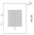
図10は、例示的AR接眼レンズ導波管スタック1000の斜視図である。接眼レンズ導波管スタック1000は、世界側カバーウィンドウ1002と、眼側カバーウィンドウ1006とを含み、カバーウィンドウ間に位置付けられる1つ以上の接眼レンズ導波管1004を保護してもよい。他の実施形態では、カバーウィンドウ1002、1006の一方または両方は、省略されてもよい。すでに議論されたように、接眼レンズ導波管1004は、層化構成において配列されてもよい。接眼レンズ導波管1004は、ともに結合されてもよく、例えば、各個々の接眼レンズ導波管は、1つ以上の隣接する接眼レンズ導波管に結合される。いくつかの実施形態では、導波管1004は、隣接する接眼レンズ導波管1004が相互に直接接触しないように、縁シール(図11に示される縁シール1108等)とともに結合されてもよい。 FIG. 10 is a perspective view of an exemplary AR
接眼レンズ導波管1004はそれぞれ、ガラス、プラスチック、ポリカーボネート、サファイア等、少なくとも部分的に透明である、基板材料から作製されることができる。選択された材料は、1.4を上回る、例えば、1.6を上回る、または1.8を上回る屈折率を有し、光誘導を促進してもよい。各接眼レンズ導波管基板の厚さは、例えば、325ミクロン以下であってもよいが、他の厚さもまた、使用されることができる。各接眼レンズ導波管は、1つ以上の内部結合領域と、光分散領域と、画像拡張領域と、外部結合領域とを含むことができ、これは、各導波管基板902上または該各導波管基板内に形成される回折特徴から成ってもよい。 The
図10に図示されないが、接眼レンズ導波管スタック1000は、それをユーザの眼の正面に支持するための物理的支持構造を含むことができる。いくつかの実施形態では、接眼レンズ導波管スタック1000は、図2に図示されるように、頭部搭載型ディスプレイシステム60の一部である。一般に、接眼レンズ導波管スタック1000は、外部結合領域が、直接、ユーザの眼の正面にあるように支持される。図10は、ユーザの眼の一方に対応する、接眼レンズ導波管スタック1000の一部のみを図示することを理解されたい。完成した接眼レンズは、可能性として鼻当てによって分離される2つの半体を伴う、同一構造の鏡像を含んでもよい。 Although not shown in FIG. 10, the
いくつかの実施形態では、接眼レンズ導波管スタック1000は、カラー画像データを複数の深度平面からユーザの眼の中に投影することができる。接眼レンズ1000内の各個々の接眼レンズ導波管1004によって表示される画像データは、選択された深度平面のための画像データの選択された色成分に対応してもよい。例えば、接眼レンズ導波管スタック1000は、6つの接眼レンズ導波管1004を含むため、2つの異なる深度平面に対応するカラー画像データ(例えば、赤色、緑色、および青色成分から成る)を投影することができる、すなわち、深度平面あたりの色成分あたり1つの接眼レンズ導波管1004となる。他の実施形態は、より多いまたはより少ない色成分および/またはより多いまたはより少ない深度平面のための接眼レンズ導波管1004を含むことができる。 In some embodiments, the
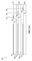
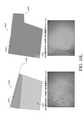
図11は、接眼レンズ導波管1104をスタックされた構成に支持するための縁シール構造1108を伴う、例示的接眼レンズ導波管スタック1100の一部の断面図である。縁シール構造1108は、接眼レンズ導波管1104を整合させ、その間に配置される空気空間または別の材料を用いて、それらを相互から分離する。図示されないが、縁シール構造1108は、スタックされた導波管構成の周全体のまわりに延在することができる。図11では、各接眼レンズ導波管間の分離は、0.027mmであるが、他の距離もまた、可能性として考えられる。 FIG. 11 is a partial cross-sectional view of an exemplary
図示される実施形態では、一方が、3m深度平面のためのものであって、他方が、1m深度平面のためのものである、赤色画像データを表示するように設計される、2つの接眼レンズ導波管1104が存在する。(再び、接眼レンズ導波管1104によって出力される光のビームの発散は、画像データを特定の距離に位置する深度平面から生じるように現れさせることができる。)同様に、一方が、3m深度平面のためのものであって、他方が、1m深度平面のためのものである、青色画像データを表示するように設計される、2つの接眼レンズ導波管1104と、一方が、3m深度平面のためのものであって、他方が、1m深度平面のためのものである、緑色画像データを表示するように設計される、2つの接眼レンズ導波管1104とが存在する。これらの6つの接眼レンズ導波管1104はそれぞれ、0.325mm厚であるように図示されるが、他の厚さもまた、可能性として考えられる。 In the illustrated embodiment, two eyepieces designed to display red image data, one for a 3 m depth plane and the other for a 1 m depth plane. There is a
世界側カバーウィンドウ1102および眼側カバーウィンドウ1106もまた、図11に示される。これらのカバーウィンドウは、例えば、0.330mm厚であることができる。6つの接眼レンズ導波管1104、7つの空気間隙、2つのカバーウィンドウ1102、1106、および縁シール1108の厚さを考慮すると、図示される接眼レンズ導波管スタック1100の総厚は、2.8mmである。 The world
(AR接眼レンズ導波管のk-空間表現)
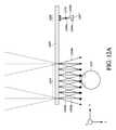
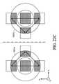
図12Aおよび12Bは、画像をユーザの眼210に向かって投影する際の動作時の接眼レンズ導波管1200の上面図を図示する。画像は、最初に、投影レンズ1210またはある他のプロジェクタデバイスを使用して、像面1207から接眼レンズ導波管1200の入射瞳1208に向かって投影されることができる。各像点(例えば、画像ピクセルまたは画像ピクセルの一部)は、光の対応する入力ビーム(例えば、1202a、1204a、1206a)を有し、これは、入射瞳1208(例えば、プロジェクタレンズ1210の光学軸に対する特定の角度)において特定の方向に伝搬する。光線として図示されるが、光の入力ビーム1202a、1204a、1206aは、例えば、それらが接眼レンズ導波管1200に入射するとき、数ミリメートル以下の直径を伴う、コリメートされたビームであってもよい。(K-space representation of AR eyepiece waveguide)
12A and 12B illustrate the top view of the
図12Aおよび12Bでは、中央像点は、入力ビーム1204aに対応し、これは、実線を用いて図示される。右側像点は、破線を用いて図示される、入力ビーム1202aに対応する。鎖線を用いて図示される、左側像点は、入力ビーム1206aに対応する。例証を明確にするために、3つのみの入力ビーム1202a、1204a、1206aが、入射瞳1208に示されるが、典型的入力画像は、2次元像面内の異なる像点に対応する、x-方向およびy-方向の両方において、ある角度範囲で伝搬する、多くの入力ビームを含むであろう。 In FIGS. 12A and 12B, the central image point corresponds to the input beam 1204a, which is illustrated with a solid line. The right image point corresponds to the
入射瞳1208における入力ビーム(例えば、1202a、1204a、1206a)の種々の伝搬角度と像面1207における個別の像点との間には、一意の対応が存在する。接眼レンズ導波管1200は、全て、像点とビーム角度との間の対応を実質的に維持しながら、入力ビーム(例えば、1202a、1204a、1206a)を内部結合し、それらを分散型様式において空間を通して複製し、それらを誘導し、入射瞳1208より大きく、複製されたビームから成る、射出瞳1210を形成するように設計されることができる。接眼レンズ導波管1200は、光の所与の入力ビーム(例えば、1202a)に変換することができ、これは、特定の角度で多くの複製されたビーム(例えば、1202b)の中に伝搬し、その特定の入力ビームおよびその対応する像点と実質的に一意に相関される角度で射出瞳1210を横断して出力される。例えば、各入力ビームに対応する複製出力ビームは、その対応する入力ビームと実質的に同一角度で接眼レンズ導波管1200から出射し得る。 There is a unique correspondence between the various propagation angles of the input beam (eg, 1202a, 1204a, 1206a) at the
図12Aおよび12Bに示されるように、光の入力ビーム1204aは、像面1207における中央像点に対応し、実線で示される、複製出力ビーム1204bのセットに変換され、これは、接眼レンズ導波管1200の射出瞳1210と垂直な光学軸と整合される。像面1207における右側像点に対応する光の入力ビーム1202aは、破線で示される、複製出力ビーム1202bのセットに変換され、これは、それらがユーザの視野の右側部分内のある場所から生じているように現れるような伝搬角度で接眼レンズ導波管1200から出射する。同様に、像面1207における左側像点に対応する光の入力ビーム1206aは、鎖線で示される、複製出力ビーム1206bのセットに変換され、これは、それらがユーザの視野の左側部分内のある場所から生じているように現れるような伝搬角度で接眼レンズ導波管1200から出射する。入力ビーム角度および/または出力ビーム角度の範囲が大きいほど、接眼レンズ導波管1200の視野(FOV)は大きくなる。 As shown in FIGS. 12A and 12B, the light input beam 1204a corresponds to the central image point on the
画像毎に、複製出力ビームのセット(例えば、1202b、1204b、1206b)、すなわち、像点あたり1セットの複製されたビームが存在し、これは、射出瞳1210を横断して異なる角度で出力される。個々の出力ビーム(例えば、1202b、1204b、1206b)はそれぞれ、コリメートされることができる。所与の像点に対応する出力ビームのセットは、平行経路(図12Aに示されるように)または発散経路(図12Bに示されるように)に沿って伝搬する、ビームから成ってもよい。いずれの場合も、複製出力ビームのセットの具体的伝搬角度は、像面1207における対応する像点の場所に依存する。図12Aは、出力ビームの各セット(例えば、1202b、1204b、1206b)が平行経路に沿って伝搬するビームから成る場合を図示する。これは、画像が光学無限遠から生じているように現れるように投影される結果をもたらす。これは、図12Aでは、周辺出力ビーム1202b、1204b、1206bから接眼レンズ導波管1200の世界側(ユーザの眼210が位置する場所と反対側)上の光学無限遠に向かって延在する、細線によって表される。図12Bは、出力ビームの各セット(例えば、1202b、1204b、1206b)が発散経路に沿って伝搬するビームから成る場合を図示する。これは、画像が光学無限遠より近い距離を有する仮想深度平面から生じているように現れるように投影される結果をもたらす。これは、図12Bでは、周辺出力ビーム1202b、1204b、1206bから接眼レンズ導波管1200の世界側上の点に向かって延在する、細線によって表される。 For each image, there is a set of duplicated output beams (eg, 1202b, 1204b, 1206b), i.e., one set of duplicated beams per image point, which is output at different angles across the
再び、複製出力ビームの各セット(例えば、1202b、1204b、1206b)は、像面1207における特定の像点に対応する、伝搬角度を有する。平行経路に沿って伝搬する複製出力ビームのセットの場合(図12A参照)、全てのビームの伝搬角度は、同一である。しかしながら、発散経路に沿って伝搬する複製出力ビームのセットの場合、個々の出力ビームは、異なる角度で伝搬し得るが、それらの角度は、それらが、集約発散波面を作成し、ビームのセットの軸に沿って共通点から生じているように現れるという点で、相互に関連する(図12B参照)。本軸は、発散出力ビームのセットに関する伝搬の角度を定義し、像面1207における特定の像点に対応する。 Again, each set of duplicate output beams (eg, 1202b, 1204b, 1206b) has a propagation angle that corresponds to a particular image point on the
接眼レンズ導波管1200に入射し、接眼レンズ導波管内を伝搬し、接眼レンズ導波管から出射する、種々の光のビームは全て、1つ以上の波ベクトル、すなわち、ビームの伝搬方向を説明する、k-ベクトルを使用して説明されることができる。k-空間は、k-ベクトルと幾何学的点を関連させる、分析フレームワークである。k-空間では、空間内の各点は、一意のk-ベクトルに対応し、これは、ひいては、特定の伝搬方向を伴う光のビームまたは光線を表すことができる。これは、その対応する伝搬角度を伴う入力および出力ビームが、k-空間内の点のセット(例えば、矩形)として理解されることを可能にする。接眼レンズを通して進行する間、光ビームの伝搬方向を変化させる、回折特徴は、k-空間では、単に、画像を構成するk-空間点のセットの場所を平行移動させるものとして理解され得る。本新しい平行移動されたk-空間場所は、新しいk-ベクトルのセットに対応し、これは、ひいては、回折特徴と相互作用後のビームまたは光線の新しい伝搬角度を表す。 The various beams of light incident on the
接眼レンズ導波管の動作は、投影された画像に対応する、k-空間矩形の内側の点等の点のセットをk-空間内で移動させる様式によって理解され得る。これは、別様に、ビームおよびその伝搬角度を図示するために使用され得る、より複雑な光線トレース図と対照的である。k-空間は、したがって、接眼レンズ導波管の設計および動作を説明するための効果的ツールである。以下の議論は、種々のAR接眼レンズ導波管の特徴および機能のk-空間表現を説明する。 The operation of the eyepiece waveguide can be understood by the mode of moving a set of points, such as points inside a k-space rectangle, in k-space, corresponding to the projected image. This is in contrast to the more complex ray trace diagrams that can be used to illustrate the beam and its propagation angle. K-space is therefore an effective tool for explaining the design and operation of eyepiece waveguides. The following discussion describes the k-space representation of the features and functions of various AR eyepiece waveguides.
図13Aは、光線または光ビームの伝搬方向を表すために使用され得る、k-ベクトル1302を図示する。特定の図示されるk-ベクトル1302は、平面波面1304を伴う、平面波を表す。k-ベクトル1302は、それが表す、光線またはビームの伝搬方向を指す。k-ベクトル1302の大きさ、すなわち、長さは、波数kによって定義される。分散式ω=ckは、光の角周波数ω、光の速さc、および波数kを関連させる。(真空では、光の速さは、光の速さの定数cと等しい。しかしながら、媒体内では、光の速さは、媒体の屈折率に反比例する。したがって、媒体では、方程式は、k=nω/cとなる。)定義上、k=2π/λおよびω=2πfであって、式中、fは、光の周波数(例えば、ヘルツ単位)であることに留意されたい。本方程式から明白となるように、より高い角周波数ωを伴う光ビームは、より大きい波数、したがって、より大きい大きさのk-ベクトル(同一伝搬媒体と仮定する)を有する。例えば、同一伝搬媒体と仮定すると、青色光ビームは、赤色光ビームより大きい大きさのk-ベクトルを有する。 FIG. 13A illustrates a k-
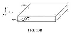
図13Bは、平面導波管1300内のk-ベクトル1302に対応する光線1301を図示する。導波管1300は、本明細書に説明される導波管のいずれかを表し得、ARディスプレイシステムのための接眼レンズの一部であり得る。導波管1300は、全内部反射(TIR)を介して、あるk-ベクトルを有する光線を誘導することができる。例えば、図13Bに示されるように、k-ベクトル1302によって図示される光線1301は、ある角度で導波管1300の上側表面に向かって指向される。角度が、スネルの法則によって統制されるように、あまり急峻ではない場合、光線1301は、入射角と等しい角度で、導波管1300の上側表面において反射し、次いで、導波管1300の下側表面に向かって下方に伝搬し、そこで、再び、上側表面に向かって戻るように反射するであろう。光線1301は、導波管1300内で誘導方式において伝搬し、その上側表面と下側表面との間で往復して反射し続けるであろう。 FIG. 13B illustrates a
図13Cは、屈折率nを伴う非境界均質媒体内を伝搬する、所与の角周波数ωの光に関する許容可能k-ベクトルを図示する。図示されるk-ベクトル1302の長さ、すなわち、大きさkは、光の速さの定数cによって除算される、媒体の屈折率n×光の角周波数ωと等しい。屈折率nを伴う均質媒体内を伝搬する、所与の角周波数ωを伴う光線またはビームに関して、全ての許容可能k-ベクトルの大きさは、同一である。また、非誘導伝搬に関して、全ての伝搬方向が、許容される。したがって、全ての許容可能k-ベクトルを定義する、k-空間内の多様体は、中空球体1306であって、球体のサイズは、光の角周波数および媒体の屈折率に依存する。 FIG. 13C illustrates an acceptable k-vector for light at a given angular frequency ω propagating in a non-boundary homogeneous medium with a refractive index n. The length of the illustrated k-
図13Dは、屈折率nを伴う均質平面導波管媒体内を伝搬する、所与の角周波数ωの光に関する許容可能k-ベクトルを図示する。非境界媒体内では、全ての許容可能k-ベクトルは、中空球体1306上にあるが、平面導波管内の許容可能k-ベクトルを決定するために、平面(例えば、x-y平面)上の許容可能k-ベクトルの球体1306を投影することができる。これは、平面導波管内を伝搬し得る、k-ベクトルを表す、投影されたk-空間内の中実円板1308をもたらす。図13Dに示されるように、x-y平面における平面導波管(例えば、導波管1300)内を伝搬し得る、k-ベクトルは全て、x-y平面におけるk-ベクトルの成分が、光の速さの定数cによって除算される媒体の屈折率n×光の角周波数ω以下であるものである。 FIG. 13D illustrates an acceptable k-vector for light at a given angular frequency ω propagating in a homogeneous planar waveguide medium with a refractive index n. Within the non-boundary medium, all acceptable k-vectors are on the
中実円板1308内の全ての点が、導波管内を伝搬し得る、波のk-ベクトルに対応する(但し、これらのk-ベクトルの全てが、図13Eに関して下記に議論されるように、導波管内の誘導伝搬をもたらすわけではない)。中実円板1308内の各点では、2つの許容される波が存在する。すなわち、1つは、ページの中に向かう伝搬のz-成分を伴うものであって、もう1つは、ページから外に向かう伝搬のz-成分を伴うものである。したがって、k-ベクトルの面外成分kzは、方程式
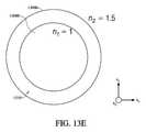
図13Eは、屈折率n2(例えば、n2=1.5)を有する導波管内で誘導され得る、光波のk-ベクトルに対応する、k-空間内の環1310を図示する。導波管は、より低い屈折率n1
本明細書に説明される種々のAR接眼レンズ導波管は、回折構造等の回折特徴を使用することによって、光を内部結合し、(例えば、プロジェクタからの)自由空間
図13Eにおけるより大きい円板1308aの半径はまた、光の角周波数ωおよび環1310の幅に依存し、したがって、光の色に依存するが、これは、FOVに対応する任意の所与の角度範囲が、同様に、角周波数に正比例してスケーリングされるため、接眼レンズ導波管によって支持されるFOVが、より高い角周波数を伴う光に関してより大きいことを含意するわけではない。 The radius of the
図13Fは、図13Eに描写されるものに類似するk-空間略図を示す。k-空間略図は、屈折率n1の第1の媒体内の許容可能k-ベクトルに対応する、より小さい円板1308bと、屈折率n2(n2>n1)の第2の媒体内の許容可能k-ベクトルに対応する、より大きい円板1308aと、より小さい円板1308aおよびより大きい円板1308bの外側境界間の環1310とを示す。環1310の幅1342内の全てのk-ベクトルは、誘導伝搬角度に対応するが、環1310の幅1342内にあるk-ベクトルの全てより少ないものが、画像を表示する際に使用するために十分であり得ることも可能性として考えられる。FIG. 13F shows a k-space schematic similar to that depicted in FIG. 13E. The k-space schematic shows a
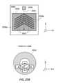
図13Fはまた、相互と比較して示される2つの誘導ビームを伴う、導波管1350を示す。第1の光ビームは、環1310の外側縁の近傍の第1のk-ベクトル1344aを有する。第1のk-ベクトル1344aは、屈折率n1の空気によって囲繞される屈折率n2を有する導波管1350の断面図に示される、第1のTIR伝搬経路1344bに対応する。k-空間環1310の中心により近い第2のk-ベクトル1346aを有する、第2の光ビームもまた、示される。第2のk-ベクトル1346aは、導波管1350内の第2のTIR伝搬経路1346bに対応する。導波管1350は、導波管1350上または該導波管内に回折格子1352を含んでもよい。光ビームが、回折格子1352を伴う導波管1350の表面に遭遇すると、相互作用が生じ、これは、ビームが導波管内でTIRし続ける間、光ビームエネルギーのサンプルを導波管から外に送出し得る。光ビームが導波管を通してTIRで伝搬する、角度は、回折格子1352を伴う導波管1350の表面に対する単位長あたりの反射イベントの密度、すなわち、バウンスの数を決定する。光ビーム比較の実施例に戻ると、第1のTIR伝搬経路1344b内の第1の光ビームは、回折格子1352を伴う導波管表面から、4回反射し、回折格子1352の長さにわたって4つの射出瞳1354(実線を用いて図示される)を生産する一方、第2のTIR伝搬経路1346b内の第2の光ビームは、同一または類似距離にわたって、回折格子1352を伴う導波管表面から、10回反射し、回折格子1352の長さを横断して、10の射出瞳1356(破線を用いて図示される)を生産する。FIG. 13F also shows a
実際は、出力ビーム、すなわち、射出瞳間隔を事前に選択された範囲と等しいまたはその中に制約し、ユーザに、投影されたコンテンツが事前に定義されたアイボックス内の任意の位置から見えるであろうことを確実にすることが望ましくあり得る。本情報を用いることで、環1310の幅1342を、本制約が該当する、k-ベクトル1344のサブセットに限定し、過度のかすめ入射角の角度が設計計算内に含まれないように除外することが可能である。サブセット1344より多いまたはより少ない角度も、所望の性能、回折格子設計、および他の最適化要因に応じて、容認可能であり得る。同様に、いくつかの実施形態では、導波管の表面に対してあまりに急峻であって、回折格子1352とあまりに多くの相互作用を提供する、伝搬角度に対応するk-ベクトルもまた、使用から除外されてもよい。そのような実施形態では、環1310の幅1342は、使用可能角度の境界をより大きい円板1308aとより小さい円板1308bとの間の境界から半径方向外向きに事実上移動させることによって減少されることができる。本明細書に開示される接眼レンズ導波管のいずれかの設計は、k-空間環の幅1310をこのように制約することによって調節されることができる。 In fact, the output beam, ie, the exit pupil spacing is constrained to or within a preselected range, and the projected content is visible to the user from any position within the predefined eyebox. It may be desirable to ensure deafness. By using this information, the
上記に説明されるように、準最適TIR伝搬経路に対応する、環1310内のk-ベクトルは、接眼レンズ設計計算における使用から省略され得る。代替として、過度のかすめ角の角度を伴うTIR伝搬経路、したがって、回折格子を伴う導波管の表面上のあまりに少ない反射イベントの密度に対応する、k-ベクトルは、本明細書に説明される種々の技法を使用して、補償されてもよい。1つの技法は、内部結合格子を使用して、入射画像の視野(FOV)の一部をk-空間環1310の2つの異なる面積に指向することである。特に、入射画像を、第1のk-ベクトルの群によって表されるk-空間環1310の第1の側および第2のk-ベクトルの群によって表されるk-空間環1310の第2の側に指向することが有利であり得、k-空間環1310の第1および第2の側は、相互から実質的に対向する。例えば、第1のk-ベクトルの群は、環1310の左側のk-ベクトルのFOV矩形に対応し得、第2のk-ベクトルの群は、環1310の右側のk-ベクトルのFOV矩形に対応し得る。左FOV矩形は、その左縁をより大きい円板1308aの外側縁の近傍に有し、かすめ入射角近傍k-ベクトル角度に対応する。本縁における光は、疎隔射出瞳を生産するであろう。しかしながら、環1310の右側に位置する、右FOV矩形の同一左縁は、より大きい円板1308aの中心により近いであろう。右FOV矩形の同一左縁における光は、高密度の射出瞳を有するであろう。したがって、左および右FOV矩形が、再結合され、導波管からユーザの眼に向かって出射し、画像を生産するとき、十分な数の射出瞳が、視野の全ての面積において生産される。 As described above, the k-vector in the
回折格子等の回折特徴は、光を、接眼レンズ導波管の中に、接眼レンズ導波管から外に結合し、および/または接眼レンズ導波管内の光の伝搬方向を変化させるために使用されることができる。k-空間内では、特定のk-ベクトルによって表される光線または光のビームに及ぼされる回折格子の効果は、ある格子ベクトルを伴う回折格子の平面におけるk-ベクトル成分のベクトル追加によって決定される。格子ベクトルの大きさおよび方向は、回折格子の具体的性質に依存する。図13G、13H、および13Iは、k-空間内のk-ベクトルに及ぼされる回折格子の作用を図示する。 Diffractive features such as diffraction grids are used to couple light into the eyepiece waveguide and outward from the eyepiece waveguide and / or to change the direction of light propagation within the eyepiece waveguide. Can be done. In k-space, the effect of a grating on a ray or beam of light represented by a particular k-vector is determined by the addition of a vector of k-vector components in the plane of the grating with a lattice vector. .. The size and direction of the grating vector depends on the specific properties of the diffraction grating. FIGS. 13G, 13H, and 13I illustrate the action of the grating on the k-vector in k-space.
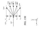
図13Gは、回折格子1320の上面図およびその関連付けられたk-空間回折格子ベクトルのうちのいくつか(G-2、G-1、G1、G2)を図示する。回折格子1320は、x-y平面に配向され、図13Gは、z-方向からその上に入射する、光線またはビームの視点からの格子の図を示す。回折格子1320は、回折格子と同一平面に配向される、k-空間回折格子ベクトル(例えば、G-2、G-1、G1、G2)の関連付けられたセットを有する。G1およびG-1格子ベクトルは、それぞれ、±1回折次数に対応する一方、G2およびG-2格子ベクトルは、それぞれ、±2回折次数に対応する。±1回折次数に関する格子ベクトルは、(格子の周期性軸に沿って)反対方向を指し、回折格子1320の周期Λに反比例する、等しい大きさを有する。したがって、より細かいピッチを伴う回折格子は、より大きい格子ベクトルを有する。±2回折次数に関する格子ベクトルもまた、反対方向を指し、±1回折次数に関する格子ベクトルの2倍の等しい大きさを有する。付加的なより高い回折次数に関する格子ベクトルもまた存在し得るが、それらは、図示されない。例えば、±3回折次数に関する格子ベクトルの大きさは、±1回折次数に関する格子ベクトルの3倍等と続く。基本格子ベクトルG1は、単に、格子の周期性(方向およびピッチ)によって決定される一方、格子の組成(例えば、表面プロファイル、材料、層構造)は、回折効率および回折位相等の格子の他の特性に影響を及ぼし得ることに留意されたい。基本格子ベクトル(例えば、G-1、G2、G-2等)の全てのハーモニクスは、単に、基本G1の整数倍数であるため、格子の全ての回折方向は、単に、格子の周期性によって決定される。回折格子1320の作用は、格子ベクトルを入射光線またはビームに対応するk-ベクトルの面内成分に追加することである。これは、図13Hに示される。FIG. 13G illustrates a top view of the
図13Hは、回折格子1320の横面図および法線入射光線または光のビームに対応するk-ベクトル1302に及ぼされるk-空間内のその効果を図示する。回折格子1320は、入射光線または光のビームを1つ以上の回折次数に回折する。これらの回折次数のそれぞれにおける新しい光線または光のビームは、新しいk-ベクトル(例えば、1302a-e)によって表される。これらの新しいk-ベクトル(例えば、1302a-e)は、格子ベクトル(例えば、G-2、G-1、G1、G2)のそれぞれを伴うk-ベクトル1302の面内成分のベクトル追加によって決定される。法線入射光線または光のビームの図示される場合では、k-ベクトル1302は、回折格子のx-y平面に成分を有していない。したがって、回折格子1320の効果は、そのk-ベクトル(例えば、1302a-e)が対応する格子ベクトルと等しいx-y成分を有する、1つ以上の新しい回折される光線または光のビームを作成することである。例えば、入射光線または光のビームの±1回折次数のx-y成分は、それぞれ、G1およびG-1となる。一方、新しいk-ベクトルの大きさは、2π/ωに制約され、したがって、新しいk-ベクトル(例えば、1302a-e)は全て、図13Hに示されるように、半円形上にある。入射k-ベクトル1302の面内成分が、その長さが基本インクリメントと等しい、または基本インクリメントの2倍等である、格子ベクトルに追加されている一方、各結果として生じるk-ベクトルの大きさが、制約されるため、種々の回折次数に関するk-ベクトル(例えば、1302a-e)間の角度は、等しくない。むしろ、k-ベクトル(例えば、1302a-e)は、回折次数の増加に伴って、より角度的に疎隔となる。FIG. 13H illustrates the side view of the
平面接眼レンズ導波管上または該平面接眼レンズ導波管内に形成される、回折格子の場合、新しいk-ベクトル(例えば、1302a-e)の面内成分は、それらが接眼レンズ導波管のk-空間環1310内にある場合、回折される光線または光のビームが、接眼レンズ導波管を通して、誘導伝搬を受けるであろうため、最も着目され得る。しかし、新しいk-ベクトル(例えば、1302a-e)の面内成分が、中心円板1308b内にある場合、回折される光線または光のビームは、接眼レンズ導波管から出射するであろう。 In the case of diffractive lattices formed on or within the planar eyepiece waveguide, the in-plane components of the new k-vector (eg, 1302a-e) are those of the eyepiece waveguide. Within the k-
図13Iは、回折格子1320の横面図および斜入射光線または光のビームに対応するk-ベクトル1302に及ぼされるk-空間内のその効果を図示する。効果は、図13Hに関して説明されるものに類似する。具体的には、回折される光線または光のビームのk-ベクトルは、格子ベクトル(G-2、G-1、G1、G2)を伴う入射k-ベクトルの面内成分のベクトル追加によって決定される。斜入射k-ベクトル1302に関して、回折格子1320のx-y平面におけるk-ベクトルの成分は、非ゼロである。本成分は、格子ベクトルに追加され、回折される光線または光のビームに関する新しいk-ベクトルの面内成分を決定する。新しいk-ベクトルの大きさは、2π/ωに制約される。また、再び、回折される光線または光のビームのk-ベクトルの面内成分が、接眼レンズ導波管のk-空間環1310内にある場合、回折される光線または光のビームは、接眼レンズ導波管を通して、誘導伝搬を受けるであろう。FIG. 13I illustrates the side view of the
図13Jは、AR接眼レンズ導波管(例えば、1200、1300)の中に投影される画像の視野(FOV)を図示する、k-空間略図である。k-空間略図は、接眼レンズ導波管内を伝搬し得る光ビームまたは光線のk-ベクトルを定義する、より大きい円板1308aを含む。k-空間略図はまた、接眼レンズ導波管を囲繞する空気等の媒体内を伝搬し得る光ビームまたは光線のk-ベクトルを定義する、より小さい円板1308bを含む。また、すでに議論されたように、k-空間環1310は、接眼レンズ導波管内で誘導伝搬を受け得る、光ビームまたは光線のk-ベクトルを定義する。 FIG. 13J is a k-space schematic illustrating a field of view (FOV) of an image projected into an AR eyepiece waveguide (eg, 1200, 1300). The k-space schematic includes a
接眼レンズ導波管の入射瞳の中に投影される、入力ビーム(例えば、1202a、1204a、1206a)が、図12Aおよび12Bに示される。各入力ビームは、像面内の対応する像点の空間場所によって一意に定義される、伝搬角度を有する。入力ビームのセットは、x-方向およびy-方向の両方にある角度広がりを有する。x-方向における角度広がりは、水平視野を定義し得る一方、y-方向における角度広がりは、垂直視野を定義し得る。加えて、例えば、x-方向とy-方向との間の対角線に沿った入力ビームの角度広がりは、対角線視野を定義し得る。 Input beams (eg, 1202a, 1204a, 1206a) projected into the entrance pupil of the eyepiece waveguide are shown in FIGS. 12A and 12B. Each input beam has a propagation angle that is uniquely defined by the spatial location of the corresponding image point in the image plane. The set of input beams has angular spreads in both the x- and y- directions. An angular spread in the x-direction can define a horizontal field of view, while an angular spread in the y- direction can define a vertical field of view. In addition, for example, the angular spread of the input beam along the diagonal between the x- and y- directions can define a diagonal field of view.
k-空間内では、入力画像の視野は、FOV矩形1330によって近似され得る。FOV矩形1330は、入力光ビームのセットに対応する、k-ベクトルのセットを包囲する。FOV矩形1330は、kx-軸に沿った寸法を有し、これは、x-方向における入力ビームの角度広がりに対応する。具体的には、FOV矩形1330の水平幅は、

図13Jに示されるように、FOV矩形1330は、より小さい円板1308b上に中心合わせされ、その中に完全に位置する。FOV矩形1330の本位置は、入力ビームのセット(例えば、画像源からの軸上、すなわち、テレセントリック投影を伴う構成において)、または、概して、±z-方向に伝搬する、出力ビームのセット(但し、ビームのセットは、z-軸上に中心合わせされ、入射瞳または射出瞳に対して法線のものを除く、ビームは全て、±z-方向に対してある程度の量の角度逸脱を有する)のk-ベクトルに対応する。換言すると、FOV矩形1330は、k-空間略図内のより小さい円板1308b内にあるとき、それらが、画像源から、自由空間を通して、接眼レンズ導波管に伝搬するにつれた、入力ビームを表すことができる。また、それらが接眼レンズ導波管からユーザの眼に伝搬するにつれた、出力ビームを表すことができる。FOV矩形1330内の各k-空間点は、入力ビーム方向のうちの1つまたは出力ビーム方向のうちの1つを表す、k-ベクトルに対応する。FOV矩形1330によって表される入力ビームが、接眼レンズ導波管内で誘導伝搬を受けるために、FOV矩形1330は、k-空間環1310に平行移動されなければならない。逆に言えば、FOV矩形1330によって表される出力ビームが、接眼レンズ導波管から出射するために、FOV矩形1330は、k-空間環1310からより小さい円板1308bに逆平行移動されなければならない。導波管を通した伝搬から幾何学的および色分散を導入しないために、入力ビームのFOV矩形1330は、出力ビームのFOV矩形と一致し得る。すなわち、本構成では、接眼レンズ導波管は、入力から出力までビーム角度を保存する。 As shown in FIG. 13J, the
以下の方程式は、いくつかの接眼レンズ導波管内で達成され得る、FOVを説明する。

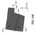
図13Kは、接眼レンズ導波管の入射瞳に位置する入力結合格子(ICG)によって生じる、FOV矩形1330のk-空間内の平行移動偏移を示す、k-空間略図である。ICGは、図13G-13Iに関して議論されたばかりのように、関連付けられた回折格子ベクトル(G-1、G1)を有する。ICGは、FOV矩形1330によって表される入力ビームのそれぞれを+1回折次数および-1回折次数に回折する。k-空間内では、+1回折次数への入力ビームの回折は、G1格子ベクトルによってkx-方向に変位されたFOV矩形1330によって表される。同様に、k-空間内では、-1回折次数への入力ビームの回折は、G-1格子ベクトルによって-kx-方向に変位されたFOV矩形1330によって表される。FIG. 13K is a k-space schematic showing the translational shift in k-space of the
図13Kに示される特定の実施例に関して、平行移動されたFOV矩形は、大きすぎて、k-空間環1310内に全体的に適合することができない。これは、接眼レンズ導波管が、それらの間の角度広がりが大きすぎるため、正または負の回折次数にあるかどうかにかかわらず、誘導伝搬モードにおけるFOV内の入力ビームの全てを支持することができないことを意味する。より大きい円板1308a外にある、平行移動されたFOV矩形内の点に対応するk-ベクトルは、それらのk-ベクトルが許容されないため、ICGによって全く回折されないであろう。(これはまた、この場合、それらの次数と関連付けられた格子ベクトルが、より長く、したがって、k-ベクトルをより大きい円板1308aのさらに外側に平行移動させるであろうため、±2およびより高い回折次数への回折を防止するであろう。)一方、平行移動されたFOV矩形の任意の部分が、ICGによる平行移動後、依然として、より小さい円板1308bの内側にあることになる場合、それらの特定のk-ベクトルに対応する光ビームは、TIRしないため、その平面を通して透過することによって、接眼レンズ導波管から出射し、導波管を通して誘導伝搬を受けないであろう。 For the particular embodiment shown in FIG. 13K, the translated FOV rectangle is too large to fit entirely within the k-
誘導モードにおける平行移動されたFOV矩形1330によって表される光の入力ビームの多くを支持するために行われ得る、1つの可能性として考えられる修正は、接眼レンズ導波管および周囲媒体の屈折率間の差異を増加させることであり得る。これは、より大きい円板1308aのサイズを増加させ、および/またはより小さい円板1308bのサイズを減少させ(より小さい円板1308bのサイズの減少は、導波管が空気によって囲繞されない場合、可能である)、それによって、k-空間環1310のサイズを増加させるであろう。 One possible modification that can be made to support many of the input beams of light represented by the translated
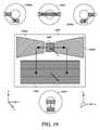
(直交瞳エクスパンダを伴う例示的AR接眼レンズ導波管)
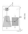
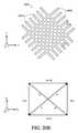
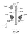
図14Aは、ICG領域1440、直交瞳エクスパンダ(OPE)領域1450、および射出瞳エクスパンダ(EPE)領域1460を伴う、例示的接眼レンズ導波管1400を図示する。図14Bは、k-空間内の接眼レンズ導波管1400のこれらのコンポーネントのそれぞれの効果を図示する、k-空間略図を含む。接眼レンズ導波管1400のICG領域1440、OPE領域1450、およびEPE領域1460は、種々の回折特徴を含み、これは、入力ビームを接眼レンズ導波管の中に結合し、誘導モードを介して伝搬し、ビームを空間内の複数の分散場所において複製し、複製ビームを接眼レンズ導波管から出射させ、ユーザの眼に向かって投影させる。(Exemplary AR eyepiece waveguide with orthogonal pupil expander)
FIG. 14A illustrates an
入力画像に対応する入力ビームは、接眼レンズ導波管1400の中に1つ以上の入力デバイスから投影されることができる。入力ビームは、接眼レンズ導波管1400の入射瞳と一致し得る、ICG領域1440上に入射することができる。入力ビームを投影するために使用される入力デバイスは、例えば、空間光変調器プロジェクタ(ユーザの顔に対して接眼レンズ導波管1400の正面または背後に位置する)を含むことができる。いくつかの実施形態では、入力デバイスは、液晶ディスプレイ(LCD)、シリコン上液晶(LCoS)、ファイバ走査ディスプレイ(FSD)技術、または走査型微小電気機械システム(MEMS)ミラーディスプレイを使用してもよいが、その他もまた、使用されることができる。入力デバイスからの入力ビームは、概して、図示される-z-方向において、種々の伝搬角度で、接眼レンズ導波管1400の中に投影され、接眼レンズ導波管の基板の外側からICG領域1440上に入射する。 The input beam corresponding to the input image can be projected from one or more input devices into the
ICG領域1440は、それらが、全内部反射を介して、接眼レンズ導波管1400の内側で伝搬するように、入力ビームを再指向する、回折特徴を含む。いくつかの実施形態では、ICG領域1440の回折特徴は、図示されるy-方向に垂直に延在し、図示されるx-方向に水平に周期的に繰り返される、多くのラインから成る、1次元周期(1D)回折格子を形成してもよい。いくつかの実施形態では、ラインは、接眼レンズ導波管1400の正面または背面の中にエッチングされてもよく、および/またはそれらは、正面または背面上に堆積される材料から形成されてもよい。ラインの周期、デューティサイクル、深度、プロファイル、ブレーズ角度等は、それに関して接眼レンズ導波管1400が設計される光の角周波数ω、格子の所望の回折効率、および他の要因に基づいて、選択されることができる。いくつかの実施形態では、ICG領域1440は、主に、入力光を+1および-1回折次数に結合するように設計される。(回折格子は、0次回折次数および1次回折次数を超えるより高い回折次数を低減または排除するように設計されることができる。これは、各ラインのプロファイルを適切に成形することによって遂行されることができる。しかしながら、ARディスプレイ内の多くの実践的ICGでは、全てのより高い回折次数は、k-空間環を超える、k-ベクトルに対応する。したがって、それらのより高い回折次数は、格子デューティサイクル、深度、およびプロファイルのような非k-空間属性にかかわらず、禁止されるであろう。)ICG領域1440からの±1回折次数のうちの一方における回折ビームは、次いで、概して、-x-方向において、OPE領域1450に向かって伝搬する一方、±1回折次数の他方における回折ビームは、次いで、概して、+x-方向において伝搬し、接眼レンズ導波管1400から出射する。 The
OPE領域1450は、少なくとも2つの機能を実施し得る、回折特徴を含む。第1に、それらは、概して、-x-方向における多くの新しい場所において、各光の入力ビームを空間的に複製することによって、瞳拡張を実施することができる。第2に、それらは、各複製された光のビームを、概して、EPE領域1460に向かう経路上で誘導することができる。いくつかの実施形態では、これらの回折特徴は、接眼レンズ導波管1400の基板上または該基板内に形成される、ラインである。周期、デューティサイクル、深度、プロファイル、ラインのブレーズ角度等は、それに関して接眼レンズ導波管1400が設計される光の角周波数ω、格子の所望の回折効率、および他の要因に基づいて、選択されることができる。OPE領域1450の具体的形状は、変動し得るが、一般に、ICG領域1440からの光のビームの広がりおよびEPE領域1460のサイズおよび場所に基づいて決定されてもよい。これは、図14Dに関してさらに議論される。 The
OPE領域1450の回折格子は、比較的に低いおよび/または可変回折効率を用いて設計されることができる。これらの性質は、OPE領域1450が、ICG領域1440から到着する各光のビームを複製し、および/または少なくとも1つの寸法における光エネルギーをより均一に分散させることを可能にすることができる。比較的に低回折効率のため、光のビームと格子の各相互作用は、光ビーム内の屈折力の一部のみを回折する一方、残りの部分は、同一方向に伝搬し続ける。(格子の回折効率に影響を及ぼすために使用され得る、いくつかのパラメータは、ライン特徴の高さおよび幅またはライン特徴と背景媒体との間の屈折率差の大きさである。)すなわち、ビームが、OPE領域1450内の回折格子と相互作用すると、その屈折力の一部は、EPE領域1460に向かって回折されるであろう一方、残りの部分は、OPE領域内を透過し続け、再び、異なる空間場所における格子に遭遇し、そこで、ビームの屈折力の別の部分は、EPE領域1460に向かって回折される等と続き得る。各光ビームの屈折力の一部は、EPE領域1460に向かって回折される前に、他の部分よりOPE領域1450を通して遠くに進行するため、-x-方向に異なる場所からEPE領域に向かって進行する入射ビームの多数のコピーが存在する。OPE領域1450を通したオリジナル入射ビームの伝搬方向における、複製ビームの空間範囲は、したがって、事実上増加する一方、入射ビームの強度は、入力ビームを構成する光が、ここで、多くの複製ビームに分割されるため、対応して、減少する。 The grating in the
OPE領域1450内の回折格子は、ビームを、概して、EPE領域1460に向かって回折するように、ICG領域1440から到着するビームに対して斜めに配向される。OPE領域1450内の回折格子の傾斜の具体的角度は、接眼レンズ導波管1400の種々の領域のレイアウトに依存し得、おそらく、図14Bにおいて後に見出され、議論される、k-空間略図内により明確に見られ得る。接眼レンズ導波管1400内では、ICG領域1440は、OPE領域1450の右に位置する一方、EPE領域1460は、OPE領域の下方に位置する。したがって、ICG領域1440からの光をEPE領域1460に向かって再指向するために、OPE領域1450の回折格子は、図示されるx-軸に対して約45°に配向されてもよい。 The grating in the
図14Cは、図14Aおよび14Bに示されるOPE領域1450の光学作用の3次元例証である。図14Cは、ICG領域1440およびOPE領域1450を示し、その両方とも、視認者により近い導波管の側にある。格子ラインは、それらが微視的であるため、見ることができない。この場合、単一入力ビーム1401が、図示されるが、画像は、接眼レンズ導波管1400を通して若干異なる方向に伝搬する、多くのそのような入力ビームから成るであろう。入力ビーム1401は、ICG領域1440からOPE領域1450に入射する。入力ビーム1401は、次いで、全内部反射を介して、接眼レンズ導波管1400を通して伝搬し続け、その表面間で往復して繰り返し反射する。これは、図14Cでは、各ビームの図示される伝搬内のジグザグによって表される。 FIG. 14C is a three-dimensional illustration of the optical action of the
入力ビーム1401が、OPE領域1450内に形成される回折格子と相互作用すると、その屈折力の一部は、EPE領域に向かって回折される一方、その屈折力の別の部分は、同一経路に沿って、OPE領域1450を通して継続する。すでに述べられたように、これは、部分的に、格子の比較的に低回折効率に起因する。さらに、EPE領域に向かって回折されるビームは、OPE領域1450の格子に再遭遇し、入力ビーム1401のオリジナル伝搬方向に戻るように回折し得る。これらのビームの一部の経路が、図14Cに矢印によって示される。効果は、入力ビームがOPE領域1450を通して伝搬するにつれて複製されるため、光の空間範囲が拡張されることになる。これは、図14Cから明白であって、これは、入力ビーム1401が、多くの光ビームに複製され、最終的には、EPE領域に向かって、概して、-y-方向に進行することを示す。 When the
EPE領域1460も同様に、少なくとも2つの機能を実施し得る、回折特徴を含む。第1に、それらは、別の方向(例えば、ビームがOPE領域1450によって複製される方向に略直交する方向)に沿って、ビームを複製することができる。第2に、それらは、各光のビームを接眼レンズ導波管1400から外にユーザの眼に向かって回折することができる。EPE領域1460は、OPE領域1450と同一方法において、光ビームを複製することができる。すなわち、ビームが、EPE領域1460を通して伝搬するにつれて、回折格子と繰り返し相互作用し、その屈折力の一部を第1の回折次数に回折し、それによって、ユーザの眼に向かって外部結合される。ビームの屈折力の他の部分は、ゼロ次回折し、後に、再び、格子と相互作用するまで、EPE領域1460内で同一方向に伝搬し続ける。EPE領域1460の回折光学特徴はまた、本明細書のいずれかで議論されるように、それらをそれらが所望の深度平面から生じたかのように現れさせるための程度の光の複製される出力ビームの屈折力を付与し得る。これは、レンズ機能を使用して、曲率をEPE領域1460内の回折格子のラインに付与することによって遂行されることができる。 The
図14Bは、接眼レンズ導波管1400のk-空間内の作用を図示する。具体的には、図14Bは、接眼レンズ導波管1400のコンポーネント毎のk-空間略図(KSD)を含み、そのコンポーネントのk-空間効果を図示する。k-空間略図内のFOV矩形および接眼レンズ導波管を通した光の対応する伝搬方向を示す矢印は、合致する陰影を有する。第1のk-空間略図KSD1は、入力デバイスからICG領域1440上に入射する、入力ビームのk-空間表現を示す。すでに議論されたように、入力ビームのセットは、そのkxおよびky寸法がx-およびy-方向における入力ビームの角度広がりに対応する、FOV矩形1430によってk-空間内に表されることができる。KSD1内におけるFOV矩形内の各具体的点は、入力ビームのうちの1つと関連付けられたk-ベクトルに対応し、kx成分は、x-方向における入力ビームの伝搬角度を示し、ky成分は、y-方向における入力ビームの伝搬角度を示す。より精密には、kx=sin(θx)であって、式中、θxは、入力ビームおよびy-z平面によって形成される角度であって、ky=sin(θy)であって、式中、θyは、入力ビームおよびx-z平面によって形成される角度である。KSD1内のFOV矩形は、略図のkz-軸上に中心合わせされるという事実は、表される入力光ビームが、-z-方向に伝搬する入力ビームを中心として中心合わせされる伝搬角度を有し、したがって、全ての入力ビームが、概して、-z-方向に伝搬することを意味する。(ここでは図示されないが、本明細書に説明される導波管ディスプレイのいずれかはまた、±z-方向に対して軸外にあるFOVのためにも設計されることができる。)FIG. 14B illustrates the action of the
第2のk-空間略図KSD2は、ICG領域1440のk-空間作用を示す。すでに議論されたように、回折格子は、関連付けられた格子ベクトル(例えば、G1、G-1)を有する。KSD2は、G1格子ベクトルおよびG-1格子ベクトルを示し、これは、大きさが等しく、ICGの周期性軸に沿った方向において反対である。ICG領域1440は、入力ビームを±1回折次数に回折する。また、k-空間内では、これは、ICGが、G1およびG-1格子ベクトルの両方を使用して、それを平行移動させることによって、FOV矩形を2つの新しい場所にコピーすることを意味する。図示されるインスタンスでは、ICGは、格子ベクトルG1、G-1の大きさが、コピーされたFOV矩形を導波管のk-空間環内に完全に設置するように、入力ビームの角周波数ωに基づく周期Λを用いて設計される。故に、回折される入力ビームは全て、誘導伝搬モードに入る。The second k-space schematic KSD2 shows the k-space effect of the
-kx-軸上の点(k-空間環内の9時位置)に中心合わせされる、FOV矩形のコピーは、対応する回折ビームが、接眼レンズ導波管1400の平面におけるその伝搬成分が-x-方向にあるビームの周囲に中心合わせされる、伝搬角度を有することを示す。したがって、それらのビームは全て、TIRを介して、接眼レンズ導波管1400の正面と背面との間で往復して反射しながら、概して、OPE領域1450に向かって伝搬する。一方、+kx-軸上の点(k-空間環内の3時位置)に中心合わせされる、FOV矩形のコピーは、対応する回折ビームが、接眼レンズ導波管1400の平面におけるその伝搬成分が+x-方向にあるビームの周囲に中心合わせされる、伝搬角度を有することを示す。したがって、それらのビームは全て、TIRを介して、接眼レンズ導波管1400の正面と背面との間で往復して反射しながら、概して、接眼レンズ導波管1400の右縁に向かって伝搬する。本特定の接眼レンズ導波管1400では、それらのビームは、概して、喪失され、ユーザの眼に向かった画像の投影に有意義に寄与しない。A copy of the FOV rectangle centered on a point on the -kx -axis (9 o'clock position in the k-space ring) has the corresponding diffracted beam and its propagating component in the plane of the
KSD2は、図示される一次格子ベクトルG1、G-1の倍数である、高次格子ベクトルを図示しない。ICGは、そのように行うことが、本インスタンスでは、許容されるk-ベクトルを定義するk-空間円板の外周を越えるFOV矩形を構成する、k-ベクトルを平行移動させるであろうため、光ビームをそれらの回折次数に回折しない。故に、より高い回折次数は、本実施形態では、生じない。KSD2 does not show a higher-order lattice vector, which is a multiple of the illustrated first-order lattice vectors G1 and G-1 . Because doing so would translate the k-vector, which in this instance constitutes a FOV rectangle beyond the perimeter of the k-space disk that defines the permissible k-vector. Do not diffract the light beam to their diffraction order. Therefore, higher diffraction order does not occur in this embodiment.
第3のk-空間略図KSD3は、OPE領域1450のk-空間作用を示す。再び、OPE領域1450は、回折格子を含むため、関連付けられた格子ベクトル(例えば、G1、G-1)を有し、これは、大きさが等しく、OPE格子の周期性軸に沿った方向において反対であり得る。この場合、回折格子の周期性軸は、x-軸に対して45°角度にある。故に、OPE回折格子の格子ベクトル(例えば、G1、G-1)は、kx-軸に対して45°角度を指す。KSD3に示されるように、格子ベクトルのうちの1つは、FOV矩形を、-ky-軸上に位置する点(k-空間環内の6時位置)に中心合わせされる新しい場所に平行移動させる。FOV矩形の本コピーは、対応する回折ビームが、接眼レンズ導波管1400の平面におけるその伝搬成分がEPE領域1460に向かって-y-方向にあるビームの周囲に中心合わせされる、伝搬角度を有することを示す。一方、他の図示されるOPE格子ベクトルは、FOV矩形をk-空間円板の外周の外側の場所に設置するであろう。しかし、円板の外側のk-ベクトルは、許容されず、したがって、OPE回折格子は、ビームをその回折次数に回折しない。OPE領域1450内の回折格子の周期性軸は、必ずしも、正確に45°である必要はない。例えば、KSD3の精査によって分るように、周期性軸は、依然として、FOV矩形をFOV矩形がk-空間環内に全体的に適合し得る6時位置に平行移動させながらも、幾分、45°より大きいまたはより小さい角度であり得る。これは、FOV矩形が、必ずしも、-ky-軸に沿ったk-空間環内に中心合わせされずに、FOV矩形を6時位置に設置するであろう。The third k-space schematic KSD3 shows the k-space effect of the
図示されるインスタンスでは、OPE回折格子は、格子ベクトルG1、G-1のうちの一方が、導波管のk-空間環内に完全にあるコピーされたFOV矩形を6時位置に設置するように、入力ビームの角周波数ωに基づく周期Λを用いて設計される。故に、回折される入力ビームは全て、誘導伝搬モードのままである。OPE格子によって実施される平行移動である、k-空間環内の9時位置から6時位置までのk-空間距離は、ICGによって実施される平行移動である、k-空間略図の原点から環までの距離を上回るため、OPE格子ベクトルは、ICG格子ベクトルと大きさが異ならなければならない。特に、OPE格子ベクトルは、ICG格子ベクトルより長く、これは、OPE格子が、したがって、ICG格子より短い周期Λを有することを意味する。In the illustrated instance, the OPE grating installs a copied FOV rectangle at 6 o'clock, where one of the lattice vectors G1 and G-1 is completely within the k-space ring of the waveguide. As such, it is designed using a period Λ based on the angular frequency ω of the input beam. Therefore, all diffracted input beams remain in guided propagation mode. The k-space distance from 9 o'clock to 6 o'clock in the k-space ring, which is the translation performed by the OPE lattice, is the translation performed by the ICG, from the origin of the k-space schematic. The OPE lattice vector must be different in magnitude from the ICG lattice vector in order to exceed the distance to. In particular, the OPE grid vector is longer than the ICG grid vector, which means that the OPE grid therefore has a shorter period Λ than the ICG grid.
第4のk-空間略図KSD4は、EPE領域1460のk-空間作用を示す。再び、EPE領域1460は、回折格子を含むため、関連付けられた格子ベクトル(例えば、G1、G-1)を有し、これは、大きさが等しく、EPE格子の周期性軸に沿った方向において反対である。この場合、回折格子の周期性軸は、接眼レンズ導波管1400のy-軸に沿っている。故に、EPE回折格子の格子ベクトル(例えば、G1、G-1)は、±ky-方向を指す。KSD4に示されるように、格子ベクトルのうちの一方は、FOV矩形を、k-空間略図の原点に中心合わせされる、新しい場所に平行移動させる。FOV矩形の本コピーは、対応する回折ビームが、接眼レンズ導波管1400の平面におけるその伝搬成分がユーザの眼に向かって+z-方向にあるビームの周囲に中心合わせされる、伝搬角度を有することを示す。一方、他方の一次EPE格子ベクトルは、FOV矩形をk-空間円板の外周の外側の場所に設置し、したがって、EPE回折格子は、ビームをその回折次数に回折しない。しかしながら、二次EPE格子ベクトルのうちの一方は、FOV矩形をk-空間環内の12時場所に平行移動させるであろう。したがって、EPE格子は、光の一部を第2の回折次数のうちの一方に回折し得る。二次回折方向は、+y-方向に沿った誘導伝搬方向に対応し得、典型的には、望ましくない効果である。例えば、二次回折は、下記に議論されるように、EPE格子が、摂動され、屈折力を導入すると、視覚的アーチファクトをもたらし、フレアまたは不鮮明化効果をユーザに提示される画像内にもたらし得る。The fourth k-space schematic KSD4 shows the k-space effect of the
図示されるインスタンスでは、EPE回折格子は、格子ベクトルG1、G-1のうちの一方が、コピーされたFOV矩形を導波管のk-空間円板の内側に完全にあるように設置するように、入力ビームの角周波数ωに基づく周期Λを用いて設計される。故に、EPE回折格子によって回折されるビームは全て、もはや誘導伝搬モードではなく、したがって、接眼レンズ導波管1400から出射する。さらに、EPE回折格子は、FOV矩形をk-空間略図の原点(入力ビームに対応するFOV矩形が位置した場所)に戻るように平行移動させるため、出力ビームは、その対応する入力ビームと同一伝搬角度を有する。図示される実施形態では、EPE回折格子は、これらの回折格子の両方がFOV矩形を同一k-空間距離だけ平行移動させるため、ICGと同一周期Λを有する。しかしながら、これは、要件ではない。FOV矩形のky寸法が、6時位置におけるk-空間環のky寸法未満である場合、FOV矩形は、環内の異なるky場所における可能性として考えられる6時位置の範囲を有することができる。故に、EPE格子ベクトル、ひいては、OPEベクトルが、FOV矩形をk-空間環内の場所および/またはk-空間略図の原点の近傍に設置するための多数のエンジニアリング選択肢が存在し得る。In the illustrated instance, the EPE grating installs one of the lattice vectors G1 and G-1 so that the copied FOV rectangle is completely inside the k-space disk of the waveguide. As such, it is designed using a period Λ based on the angular frequency ω of the input beam. Therefore, all beams diffracted by the EPE grating are no longer in guided propagation mode and therefore exit from the
いくつかの実施形態では、EPE回折格子のラインは、屈折力をEPE領域1460から出射する出力ビームに付与するように、若干湾曲されてもよい。例えば、EPE領域1460内の回折格子のラインは、負の屈折力を付与するために、導波管の平面において、OPE領域に向かって曲げられることができる。これは、例えば、図12Bに示されるように、出力ビームを発散経路に追従させるために使用されることができる。これは、投影された画像を光学無限遠より近い深度平面に現れさせる。具体的曲率は、レンズ機能によって決定されることができる。k-空間内では、これは、EPE領域1460内の異なる空間領域が、その具体的領域内の格子ラインの曲率に応じて、若干異なる方向を指す格子ベクトルを有するであろうことを意味する。これらの実施形態では、これは、FOV矩形をk-空間略図の原点の周囲に中心合わせされる種々の異なる場所に平行移動させる。これは、ひいては、平行移動されたFOV矩形のそれぞれに対応する出力ビームのセットを異なる伝搬角度の周囲に中心合わせさせ、これは、ひいては、深度の錯覚を生じさせる。 In some embodiments, the lines of the EPE grating may be slightly curved to impart refractive power to the output beam emitted from the
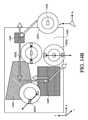
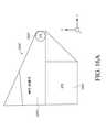
図14Dは、OPE領域1450およびEPE領域1460のサイズおよび形状を決定するための技法を図示する。図14Dは、ICG領域1440と、OPE領域1450と、EPE領域1460とを含む、図14Aおよび14Bに示されるものと同一接眼レンズ導波管1400を図示する。図14Dはまた、k-空間略図KSD1、KSD2、およびKSD3の簡略化されたバージョンを含む。第1のk-空間略図KSD1を参照すると、FOV矩形の4つの角k-ベクトルは、入力平面内の画像の角から最も斜角でICG上に入射する、入力ビームに対応するものである(図12Aおよび12B参照)。これらの入力ビームの伝搬角度は、視野内の全てのもののうちの最も極限であるため、そのk-ベクトルは、k-空間内のFOV矩形の4つの角に位置する。 FIG. 14D illustrates techniques for determining the size and shape of
図14Dは、入力画像の4つの角に対応する、ICG領域1440からの4つの回折ビームを定義する、光線を示す。特に、OPE領域1450の上部の近傍の光線は、上向き方向かつOPE領域から離れるような最急伝搬角度でICG領域1440上に入射する入力ビームに対応する、回折ビーム(すなわち、FOV矩形の右上角に位置するk-ベクトル)を定義する。また、OPE領域1450の底部の近傍の光線は、下向きかつOPE領域から離れるような最急伝搬角度でICG領域1450上に入射する入力ビームに対応する、回折ビーム(すなわち、FOV矩形の右下角に位置するk-ベクトル)を定義する。これらの2つのビームは、ICG領域1440からの回折ビームの広がりを定義する。これらの2つのビームおよびその間のその他の全ての複製されたインスタンスを作成し、それらをユーザの眼に向かって投影するために、OPE領域の上部および底部境界は、これらの2つのビームの伝搬経路を包含すべきである。その具体的伝搬経路は、第2のk-空間略図KSD2を参照して決定されることができる。 FIG. 14D shows a ray defining four diffracted beams from the
KSD2は、ICG領域1440からOPE領域1450に向かって回折する、ビームの結果として生じるk-ベクトルを示す。KSD2における矢印は、FOV矩形の右上角に位置するk-ベクトルに対応する、ビームの伝搬角度を示す。 KSD2 shows the resulting k-vector of the beam diffracting from the
EPE領域1460のサイズ、形状、および場所は、第3のk-空間略図KSD3内のk-ベクトルから明白である、伝搬角度を使用して、後方光線トレースを実施することによって決定されることができる。KSD3から明白であるように、FOV矩形の左および右上角k-ベクトルは、OPE領域1450からEPE領域1460に向かった方向に伝搬する間にビームが追従する、伝搬経路の広がりを定義する。これらの伝搬角度を使用して、OPE領域1450から最も遠く(すなわち、EPE領域の下角)に位置するEPE領域1460の部分から後方トレースすることによって、左および右上角k-ベクトルによって定義された伝搬角度を伴ってEPE領域の下角に到着するであろう、それらの光線のOPE領域内の原点を決定することができる。それらの光線のこれらの原点は、OPE領域1450の残りの境界を決定するために使用されることができる。例えば、ビームをOPE領域1450からEPE領域1460の左下角に指向するために、最悪の場合の伝搬角度は、FOV矩形の右上角k-ベクトルによって示されるものである。したがって、その角度を伴う伝搬経路は、OPE領域1450の左境界を定義するために使用されることができる。同様に、ビームをOPE領域1450からEPE領域の右下角に指向するために、最悪の場合の伝搬角度は、FOV矩形の左上角k-ベクトルによって示されるものである。したがって、その角度を伴う伝搬経路は、OPE領域1450の右境界を定義するために使用されることができる。 The size, shape, and location of the
図14Dに示されるように、図示される接眼レンズ導波管1400の場合、EPE領域1460は、ICG領域1440から-xおよび-y-方向に位置する。また、回折ビームの一部は、それらの同一方向に経路に沿ってICG領域1440から広がる。最初に、OPE領域1450を通して伝搬する前に、これらの回折ビームがEPE領域に入射することを回避するために、ICG領域1440は、回折ビームの広がりがEPE領域1460と交差しないように、+y-方向に、EPE領域から十分に離れて位置し得る。これは、OPE領域1450の下側境界線とEPE領域1460の上側境界線の間に大きな間隙をもたらす。いくつかの実施形態では、本間隙を除去または低減させることによって、接眼レンズ導波管のサイズを減少させることが望ましくあり得る。図15Aは、これらの目標を遂行する、例示的実施形態を図示する。 As shown in FIG. 14D, in the case of the illustrated
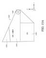
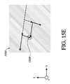
図15Aは、その中にOPE領域1550が、傾斜され、その下側境界線がEPE領域1560の上側境界線と平行であるように位置する、導波管接眼レンズ1500の例示的実施形態を図示する。実際、OPE領域1550およびEPE領域1560は、実際には、境界線を共有してもよい。本実施形態によると、導波管接眼レンズ1500のサイズは、図14Aに示される接眼レンズ導波管実施形態内のOPE領域とEPE領域との間の間隙を低減または排除することによって、よりコンパクトにされることができる。 FIG. 15A illustrates an exemplary embodiment of a
OPE領域1550の傾斜された配向に適応するために、ICG領域1540は、ICG領域からの回折ビームの広がりが、OPE領域1550の傾斜された配向に合致するように傾斜されるように、修正されることができる。例えば、ICG領域1540の格子ラインは、回折ビームが-y-方向における成分を有する伝搬方向にICG領域から出射しないように配向されることができる。加えて、ICG領域1540は、OPE領域1550およびEPE領域1560の共有境界線の近傍にあるが、ICG領域のいずれの部分もその共有境界線を越える-y-方向に延在しないように位置付けられることができる。ICG領域1540の作用は、図15Bに示されるk-空間略図に見られ得る。 To adapt to the tilted orientation of the
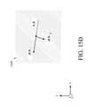
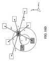
図15Bは、図15Aに示される接眼レンズ導波管1500の作用を図示する、k-空間略図を含む。第1のk-空間略図KSD1は、ICG領域1540に向かって接眼レンズ導波管1500の外側に位置するプロジェクタから投影される入力ビームに対応する、FOV矩形を示す。図示される実施形態では、これらの入力ビームは、-z-方向を中心として中心合わせされる伝搬角度を有する。したがって、k-空間内では、それらは、KSD1の原点においてkz-軸上に中心合わせされるFOV矩形によって表され得る。FIG. 15B includes a k-space schematic illustrating the action of the
第2のk-空間略図KSD2は、入力ビームに及ぼすICG領域1540の作用を示す。ICG領域1540は、入力ビームを回折し、それらをOPE領域1550に向かって再指向する。k-空間内では、これは、ICG領域1540と関連付けられた格子ベクトルを使用して、FOV矩形を平行移動させることに対応する。本実施形態では、ICG領域1540内の格子ラインは、+y-方向に成分を有する周期性軸を伴って配向される。これは、ICG1540と関連付けられた格子ベクトルもまた、+ky-方向における成分を有することを意味する。+ky-方向における本成分の大きさは、ky-方向におけるFOV矩形の幅の1/2を上回るまたはそれと等しくあり得る。これは、FOV矩形のいずれの部分も、ICG領域1540によって平行移動された後、k-空間略図KSD2の水平軸の下方に延在しないことを意味する。これは、ひいては、ICG領域1540からの回折ビームのいずれも、-ky-方向における成分を伴う伝搬角度を有していないことを意味する。故に、回折ビームのいずれも、EPE領域1560に向かってICG領域1540から下向きに進行しない。また、したがって、回折ビームのいずれも、OPE領域1550を通して通過することに先立って、EPE領域1560に入射しないであろう。The second k-space schematic KSD2 shows the effect of the
第3のk-空間略図KSD3は、ICG領域1540からの回折ビームに及ぼすOPE領域1550の作用を示す。図示されるように、OPE領域1550の回折格子は、k-空間環内の6時位置から若干変位された位置に平行移動されたFOV矩形に対応する角度で、光のビームを再指向するように、配向されることができる。例えば、KSD3内の平行移動されたFOV矩形は、KSD2内の平行移動されたFOV矩形が9時位置から変位されるにつれて、同一角度だけ、k-空間環内の6時位置から変位されることができる。換言すると、KSD3内の平行移動されたFOV矩形は、KSD2内の平行移動されたFOV矩形から90°分離されることができる。しかしながら、本具体的角度分離は、要求されない。すなわち、各FOV矩形の具体的場所は、相互に対する接眼レンズ導波管の種々の領域のレイアウトに依存し得る。 The third k-space schematic KSD3 shows the effect of the
KSD3内の平行移動されたFOV矩形は、-kx-方向における成分を有するk-ベクトルの周囲に中心合わせされるため、OPE領域1550からの光のビームは、概して、-x-方向における成分を有する角度で、EPE領域1560に向かって進行する。図15Aから、本角度に起因して、OPE領域1550の先端部分1555からの光ビームの一部は、EPE領域1560と交差しないであろうことが分り得る。OPE領域1550の先端部分1555は、EPE領域1560への光の比較的に小部分に寄与し得るため、上側先端1555を排除するサイズ利点は、任意の光学不利点に勝り得る。いくつかの実施形態では、導波管接眼レンズ1500は、したがって、OPE領域1550の上側先端1555を排除することによって、さらによりコンパクトにされることができる。Since the translated FOV rectangle in KSD3 is centered around a k-vector with a component in the -kx- direction, the beam of light from the
最後に、第4のk-空間略図KSD4は、EPE領域1560が、FOV矩形をk-空間略図の原点に戻るように平行移動させるように設計される、回折格子を有することを示す。図15Aに示される接眼レンズ導波管実施形態のためのKSD4内のFOV矩形の開始場所は、図14Aに示される接眼レンズ導波管実施形態のためのKSD4内のFOV矩形の開始場所と若干異なるため、EPE領域1560内の回折格子の設計もまた、幾分、異なる。例えば、EPE領域1560内の回折格子の格子ラインの配向は、関連付けられた格子ベクトルが、+kx-方向における成分を有し、OPE領域1550が、EPE領域1560の左縁を越えて延在する必要がないように、傾斜されることができる(図14Dの議論を参照し、かつ図14DにおけるKSD3内の右上角k-ベクトルの場所と図15BにおけるKSD3内の対応するk-ベクトルの場所を比較されたい)。これは、図15BのKSD4内のFOV矩形が、k-空間略図の原点に戻るように平行移動される結果をもたらし、これは、平行移動されたFOV矩形によって表される光のビームが、本明細書ですでに説明されたように、その対応する入力ビームと同一伝搬角度を用いて、接眼レンズ導波管1500から外にユーザの眼に向かって結合されることを意味する(すなわち、出力ビームを表すFOV矩形が、k-空間略図内において、入力ビームを表すFOV矩形と同一場所にある)。Finally, the fourth k-space schematic KSD4 shows that the
図15Cは、図15Aに示される接眼レンズ導波管1500の作用を図示する、別のk-空間略図である。図15Cにおけるk-空間略図は、図15Bに示される全てのk-空間略図の重畳である。また、OPE領域1550を通して伝搬する光ビームは、概して、-kx-方向における伝搬角度(k-空間環の9時位置の近傍に位置するFOV矩形によって表されるように)と、概して、-ky-方向における伝搬角度(k-空間環の6時位置の近傍に位置するFOV矩形によって表されるように)との間で往復して切り替わることができることも図示する。これは、k-空間環の9時位置の近傍のFOV矩形と6時位置の近傍のFOV矩形との間の両矢印を伴う格子ベクトルによって示される。図15D-15Fは、本挙動をより詳細に図示する。FIG. 15C is another k-space schematic illustrating the action of the
図15Dは、図15Aに示される接眼レンズ導波管実施形態の入力ビームとOPE領域1550との間の相互作用の第1の発生の略図である。接眼レンズ導波管1500のOPE領域1550は、周期性の方向に繰り返される平行格子ラインから成る、回折格子を含む。周期性の方向は、回折格子と関連付けられた格子ベクトルの方向を決定する。本インスタンスでは、図15Cにおける両矢印を伴う格子ベクトルは、OPE領域1550の作用を図示し、図15D-15Fに示される格子ラインの周期性の方向に沿って指すものである。 FIG. 15D is a schematic representation of the first generation of interaction between the input beam of the eyepiece waveguide embodiment shown in FIG. 15A and the
図15Dは、ICG領域1540からOPE領域1550に入射する、入力ビームを示す。入力ビームは、図15Cにおけるk-空間環の9時位置の近傍に位置するFOV矩形の中心点、すなわち、k-ベクトルに対応する、方向に伝搬するように示される。示されるように、入力ビームとOPE領域1550との間の相互作用の第1の発生は、2つの回折出力ビームをもたらす。すなわち、入力ビームの屈折力の一部は、単に、出力1として、接眼レンズ導波管1500の上部または底部表面から反射し、入力ビームと同一x-y方向に継続し(すなわち、0次回折)、入力ビームの屈折力の一部は、一次(例えば、OPE領域の一次格子ベクトルG1によって)に、出力2として下向きに回折する。出力2ビームは、図15Cにおけるk-空間環の6時位置の近傍に位置するFOV矩形の中心点、すなわち、k-ベクトルに対応する方向に伝搬するように示される。相互作用の本第1の発生後、出力1ビームおよび出力2ビームは、異なる伝搬角度を有するが、それらは両方とも、依然として、OPE領域1550内を伝搬し、したがって、図15Eおよび15Fに示されるように、OPE領域との付加的相互作用を有し得る。図示されないが、異なる伝搬角度を用いてOPE領域1550に入射する、他の入力ビームも、同様であるが、若干異なる入力および出力角度を用いて挙動するであろう。FIG. 15D shows an input beam incident on the
図15Eは、図15Aに示される接眼レンズ導波管実施形態の入力ビームとOPE領域1550との間の相互作用の第2の発生の略図である。相互作用の第1の発生に関連するビームは、破線を用いて示される一方、相互作用の第2の発生に関連するビームは、実線を用いて示される。図15Eに示されるように、相互作用の第1の発生からの出力ビーム、すなわち、出力1および出力2はそれぞれ、ここで、第1の発生において生じたものと類似するOPE領域1550との相互作用を受け得る。すなわち、図15Dからの出力1ビームからの屈折力の一部は、単に、同一x-y方向に継続する(すなわち、0次回折)一方、そのビームの屈折力の別の部分は、格子と相互作用し、下向きに再指向される(例えば、OPE領域の一次格子ベクトルG1によって)。同様に、図15Dからの出力2ビームからの屈折力の一部は、単に、領域1560に向かって下向きに継続する(すなわち、0次回折)一方、そのビームの屈折力の別の部分は、格子と相互作用し、概して、-x-方向に回折され(例えば、OPE領域の負の一次格子ベクトルG-1によって)、OPE領域1550の中に初期入力ビームと同一方向にさらに伝搬し続ける。FIG. 15E is a schematic representation of the second generation of interaction between the input beam of the eyepiece waveguide embodiment shown in FIG. 15A and the
相互作用の第2の発生が、OPE領域1550内で生じた後、結果として生じるビームのうちの2つが交差する、干渉ノード1556が存在する。干渉ノード1556に到着するためにこれらのビームのそれぞれによって追従される光学経路は、実質的に同じ長さである。したがって、同一方向に伝搬する干渉ノード1556から出射するビームは、同一または類似位相を有し得、したがって、相互に建設的または破壊的波干渉を受け得る。これは、下記に議論される、画像アーチファクトをもたらし得る。 There is an interfering
図15Fは、図15Aに示される接眼レンズ導波管実施形態の入力ビームとOPE領域1550との間の相互作用の第3の発生の略図である。相互作用の第1および第2の発生に関連するビームは、破線を用いて示される一方、相互作用の第3の発生に関連するビームは、実線を用いて示される。図15Fに示されるように、相互作用の第2の発生から生じる出力ビームはそれぞれ、再度、前の生成において生じたものと類似するOPE領域1550との相互作用を被り得る。それらのビームの屈折力の一部は、同一方向に継続する(すなわち、0次回折)一方、それらのビームの屈折力の他の部分は、一部は、概して、-x-方向に、一部は、概して、-y-方向に(すなわち、OPE領域の一次格子ベクトルG1およびG-1によって)、再指向される。概して、-x-方向に伝搬する、ビームは全て、図15Cにおけるk-空間略図のk-空間環内の9時位置の近傍に位置するFOV矩形によって表される状態にある一方、概して、-y-方向に伝搬する、ビームは全て、6時位置の近傍に位置するFOV矩形によって表される状態にある。図15Cから分かるように、1D周期性回折格子から成るOPE領域1550の場合、任意の所与の入力ビームに関して、その入力ビームに対応する光の複製ビームは、OPE領域内で2つのみの方向に進行する(但し、2つの方向は、異なる伝搬角度においてOPE領域に入射する、異なる入力ビームに関して異なるであろう)。FIG. 15F is a schematic representation of the third generation of interaction between the input beam of the eyepiece waveguide embodiment shown in FIG. 15A and the
OPE領域との相互作用の第3の発生は、同一または類似光学経路長を伴うビームが相互に交差する、付加的干渉ノード1556の作成をもたらし、可能性として、建設的または破壊的波干渉をもたらす。ノード1556はそれぞれ、EPE領域1560に向かって放出される光源としての役割を果たす。1D周期性を伴う回折格子から成る、OPE領域の場合、これらのノード1556のレイアウトは、均一格子模様パターンを形成し、したがって、図15Gに示されるように、画像アーチファクトをもたらし得る。 The third occurrence of interaction with the OPE region results in the creation of
図15Gは、ICG領域1540からの単一入力ビーム1545が、OPE領域1550によって複製され、EPE領域1560に向かって複数のビーム1565として再指向される方法を図示する、略図である。EPE領域1560に向かって、またはその中で伝搬するように示される、複製ビーム1565はそれぞれ、干渉ノード1556のうちの1つから生じる。これらの干渉ノードは、秩序付けられた分布を有し、源の疎隔された周期的アレイとしての役割を果たす。干渉ノード1556の秩序付けられた分布に起因して、EPE領域を照明する、複製ビーム1565は全て、同一間隔によって分離されるが、ビームは、非単調に変動する強度を有してもよい。また、その結果、OPE領域1550からの複製光ビーム1565は、比較的に疎隔された非均一分布を伴って、EPE領域1560を照明し得る。いくつかの実施形態では、接眼レンズ導波管のEPE領域を照明する、複製光ビームが、より均一に分散され得る場合、有利であり得る。図16は、そのような実施形態を図示する。 FIG. 15G is a schematic diagram illustrating how a
(多指向性瞳エクスパンダを伴う例示的AR接眼レンズ導波管)
図16Aは、OPE領域ではなく、多指向性瞳エクスパンダ(MPE)領域1650を有する、例示的接眼レンズ導波管1600を図示する。巨視的レベルでは、接眼レンズ導波管1600の図示される実施形態は、図15Aに示される接眼レンズ導波管1500に類似する。入力ビームは、ICG領域1640によって、接眼レンズ導波管1600の中に結合される。回折ビームは、ICG領域1640から、OPE領域に取って代わる、MPE領域1650に向かって、かつそれを通して伝搬する。最後に、MPE領域1650は、光のビームをEPE領域1660に向かって回折し、そこで、それらは、ユーザの眼に向かって外部結合される。ICG領域1640およびEPE領域1660は、図15A-15Gに関して説明される接眼レンズ導波管1500内の対応する領域と同一方法で機能するように設計されてもよい。しかしながら、MPE領域1650は、光をより多くの方向に回折するという点で、OPE領域1550と明確に異なる。本特徴は、有利なこととして、EPE領域1660内の光ビームの分布における周期的均一性を減少させ、これは、ひいては、EPE領域をより均一に照明させることができる。(Exemplary AR eyepiece waveguide with multi-directional pupil expander)
FIG. 16A illustrates an
MPE領域1650は、複数の方向において周期性を呈する、回折特徴から成る。MPE領域1650は、2D格子模様に配列される散乱特徴のアレイから成ってもよい。個々の散乱特徴は、例えば、任意の形状のくぼみまたは突出部であることができる。散乱特徴の2Dアレイは、その2D格子模様のレシプロカル格子模様から導出される、関連付けられた格子ベクトルを有する。一実施例として、MPE領域1650は、2つ以上の明確に異なる周期性の方向に沿って繰り返される格子ラインを伴う交差格子から成る、2D周期的回折格子であり得る。これは、周期性の異なる方向を伴う2つの1D格子を重畳することによって遂行されることができる。 The
図16Bは、図16Aに示されるMPE領域1650内で使用され得る、例示的2D周期的格子の一部を、その関連付けられた格子ベクトルとともに図示する。2D周期的格子1650は、その周期性の方向がベクトルuおよびvによって図示される、回折特徴の空間格子模様であることができる。そのような2D周期的格子は、格子ベクトルと関連付けられる。周期性の方向uおよびvに対応する、2つの基本格子ベクトルGおよびHは、以下によって数学的に定義される。
一実施例として、2D周期的格子は、図16Bに示されるように、2セットの1D周期的格子ラインを重畳することによって設計または形成されることができる(但し、2D周期的格子は、代わりに、例えば、図16Bに示される格子ラインの交点に位置する、個々の散乱特徴から成り得る)。第1のセットの格子ライン1656は、基本格子ベクトルGの方向に沿って繰り返されることができる。基本格子ベクトルGは、2π/aと等しい大きさを有することができ、式中、aは、第1のセットの格子ライン1656の周期である。図16Bに示される2D格子はまた、第1の基本格子ベクトルGのハーモニクスと関連付けられる。これらは、-Gおよび2G、-2G等の高次ハーモニクスを含む。第2のセットの格子ライン1657は、基本格子ベクトルHの方向に沿って繰り返されることができる。基本格子ベクトルHは、2π/bと等しい大きさを有することができ、式中、bは、第2のセットの格子ライン1657の周期である。図16Bに示される2D格子はまた、第2の基本格子ベクトルHのハーモニクスと関連付けられる。これらは、-Hおよび2H、-2H等の高次ハーモニクスを含む。 As an embodiment, a 2D periodic grid can be designed or formed by superimposing two sets of 1D periodic grid lines, as shown in FIG. 16B (although a 2D periodic grid is an alternative. In addition, for example, it may consist of individual scattering features located at the intersections of the grid lines shown in FIG. 16B). The first set of
回折特徴の任意の2D周期的アレイは、レシプロカル格子模様全体に対応し、基本格子ベクトルGおよびHの整数線形組み合わせ(重畳)によって決定された方向を指す、関連付けられた格子ベクトルを有するであろう。図示される実施形態では、これらの重畳は、付加的格子ベクトルをもたらし、これはまた、図16Bに示される。これらは、例えば、-G、-H、H+G、H-G、G-H、および-(H+G)を含む。典型的には、これらのベクトルは、(±1,0)、(0,±1)、(±1,±1)、(±2,0)等の2つのインデックスを用いて説明される。図16Bは、一次格子ベクトルおよび2D回折格子と関連付けられたその重畳のみを図示するが、高次格子ベクトルもまた、存在してもよい。 Any 2D periodic array of diffraction features will correspond to the entire reciprocal lattice pattern and will have an associated lattice vector pointing in the direction determined by the integer linear combination (superimposition) of the basic lattice vectors G and H. .. In the illustrated embodiment, these superpositions result in an additional lattice vector, which is also shown in FIG. 16B. These include, for example, —G, —H, H + G, HG, GH, and − (H + G). Typically, these vectors are described using two indexes such as (± 1,0), (0, ± 1), (± 1, ± 1), (± 2,0). FIG. 16B illustrates only the first-order lattice vector and its superposition associated with the 2D diffraction grating, but higher-order lattice vectors may also be present.
本明細書の他の場所ですでに議論されたように、画像を構成する光ビームのセットに及ぼす格子のk-空間作用は、格子と関連付けられた格子ベクトルを使用して、画像に対応するFOV矩形を平行移動させることである。これは、図16Bに示される例示的2DMPE回折格子に関して図16Cおよび16Dに示される。 As already discussed elsewhere herein, the k-space effect of a grid on the set of light beams that make up an image corresponds to the image using the grid vector associated with the grid. It is to translate the FOV rectangle. This is shown in FIGS. 16C and 16D with respect to the exemplary 2DMPE grating shown in FIG. 16B.
図16Cは、図16Aに示される接眼レンズ導波管1600のMPE領域1650のk-空間作用を図示する、k-空間略図である。k-空間略図は、k-空間環の9時位置の近傍に位置する陰影付きFOV矩形を含む。これは、ICG領域1640が、入力ビームを接眼レンズ導波管1600の中に結合し、MPE領域1650に向かって再指向した後の、FOV矩形の場所である。図16Cは、MPE領域1650内の2D格子が、図16Bに示される格子ベクトルを使用して、FOV矩形を平行移動させる方法を示す。8つの格子ベクトル(G、H、-G、-H、H+G、H-G、G-H、および-(H+G))が存在するため、MPE領域1650は、FOV矩形を8つの可能性として考えられる新しいk-空間場所に平行移動させるように試みる。これらの8つの可能性として考えられるk-空間場所のうち、6つは、k-空間略図の外周外にある。これらは、非陰影付きFOV矩形を用いて図示される。k-空間略図の境界の外側のk-ベクトルは、許容されないため、6つの格子ベクトルのうちのいずれも、回折をもたらさない。しかしながら、k-空間略図の境界内の新しい位置へのFOV矩形の平行移動をもたらす、2つの格子ベクトル(すなわち、-Gおよび-(H+G))が存在する。これらの場所のうちの一方は、k-空間環内の6時位置の近傍にあって、他方は、2時位置の近傍にある。これらの場所におけるk-ベクトルは、許容され、誘導伝搬モードをもたらすため、これらの場所におけるFOV矩形は、陰影が付けられ、光のビームがそれらの2つの状態に回折されることを示す。したがって、k-空間環の9時位置の近傍に位置するFOV矩形によって示される伝搬角度を伴ってMPE領域1650に入射する、光のビームの屈折力は、部分的に、他の2つの陰影付きFOV矩形(すなわち、2時位置の近傍のFOV矩形および6時位置の近傍のFOV矩形)によって示される状態の両方に回折される。 FIG. 16C is a k-space schematic illustrating the k-space action of the
図16Dは、図16Aに示される接眼レンズ導波管1600のMPE領域1650のk-空間作用をさらに図示する、k-空間略図である。本特定のk-空間略図は、k-空間環の2時位置の近傍に位置するFOV矩形によって図示される伝搬状態にある、光のビームへのMPE領域1650の作用を図示する。再び、MPE領域1650内の2D回折格子は、これらの光のビームをその8つの関連付けられた格子ベクトルによって規定された回折次数に回折するように試みる。示されるように、格子ベクトルのうちの6つは、FOV矩形をk-空間略図の境界の外側の位置に平行移動させるであろう。したがって、それらの回折次数は、生じない。これらの位置は、非陰影付きFOV矩形を用いて図示される。しかしながら、格子ベクトルのうちの2つ(すなわち、HおよびH-G)は、FOV矩形をk-空間略図の境界内の位置に平行移動させる。これらは、k-空間環の9時位置の近傍および6時位置の近傍に位置する陰影付きFOV矩形によって図示される。したがって、MPE領域1650内の2D回折格子は、部分的に、k-空間環の2時位置の近傍に位置するFOV矩形によって示される方向に伝搬するビームの屈折力を他の2つの陰影付きFOV矩形(すなわち、9時位置の近傍のFOV矩形および6時位置の近傍のFOV矩形)によって示される状態の両方に回折する。 FIG. 16D is a schematic k-space diagram further illustrating the k-space effect of the
図示されないが、類似k-空間略図が、k-空間環の6時位置の近傍に位置するFOV矩形によって示される伝搬角度を伴って進行する光のビームに及ぼすMPE領域1650のk-空間作用を図示するように導き出され得る。そのk-空間略図は、MPE領域1650内の2D周期回折格子が、部分的に、それらのビームの屈折力をk-空間環の9時位置の近傍および2時位置の近傍に位置する2つの陰影付きFOV矩形によって示される状態の両方に回折することを示すであろう。 Although not shown, a similar k-space schematic shows the k-space effect of the
図16Eは、図16Aに示される接眼レンズ導波管1600のk-空間作用を図示する、k-空間略図である。すでに述べられたように、接眼レンズ導波管1600は、概して、-z-方向に伝搬し、外側源から導波管1600のICG領域1640上に入射する、光の入力ビームを受け取ることができる。それらの入力ビームは、k-空間略図の原点におけるkz-軸上に中心合わせされる、FOV矩形によって表される。ICG領域1640は、次いで、それらが、誘導され、k-空間環の9時位置の近傍に位置するFOV矩形の中心点に対応する伝搬方向の周囲に中心合わせされる、伝搬角度を有するように、入力ビームを回折する。FIG. 16E is a schematic k-space diagram illustrating the k-space action of the
誘導ビームは、MPE領域1650に入射し、そこで、それらは、複数の相互作用を有することができる。相互作用の各生成の間、ビームのそれぞれの屈折力の一部は、ゼロ次回折し、MPE領域1650を通して、同一方向に伝搬し続けることができる。相互作用の第1の発生では、例えば、本ゼロ次回折は、k-空間環の9時位置の近傍に位置するFOV矩形によって示される状態に留まる、それらのビームの屈折力のその部分に対応する。ビームの屈折力の他の部分は、新しい方向に回折されることができる。再び、相互作用の第1の発生では、これは、k-空間環の2時位置の近傍に位置するFOV矩形の中心点に対応する伝搬方向の周囲に中心合わせされる、伝搬角度と、6時位置の近傍に位置するFOV矩形の中心点に対応する、伝搬方向とを有する、個別の回折ビームを作成する。 The guided beams are incident on the
ビームが、MPE領域1650内に留まる限り、それらは、付加的相互作用を被り、それぞれ、ゼロ次回折し、同一方向に継続する、または新しい方向に回折される、ビームの屈折力の部分をもたらし得る。これは、図16Eに示されるk-空間環内のFOV矩形の中心点によって示される伝搬方向のそれぞれの周囲に中心合わせされる伝搬角度を有する、空間的に分散された回折ビームのセットをもたらす。本挙動は、k-空間環内の各対のFOV矩形間の両矢印によって表される。 As long as the beams remain within the
任意の所与の光の入力ビームは、MPE領域1650内を伝搬するにつれて、3つの許容方向にのみ進行し得る、多くの回折ビームに分裂され、各方向は、図16Eにおけるk-空間略図の環内のFOV矩形内の対応するk-ベクトル、すなわち、点によって定義される。(これは、MPE領域1650内を伝搬する任意の光の入力ビームに該当する。しかしながら、3つの許容方向は、各初期入力ビームがMPE領域1650に入射する伝搬角度に応じて、若干異なるであろう。)また、任意の所与の光の入力ビームの屈折力の一部は、MPE領域1650との任意の数の相互作用後、同一3つの伝搬方向のいずれかに回折されるため、画像情報は、これらの相互作用全体を通して保存される。 As the input beam of any given light propagates within the
OPE領域1550の2つの許容可能伝搬方向とは対照的に、入力ビーム毎に3つの許容可能伝搬方向を有する、MPE領域1650と関連付けられた利点が存在する。これらの利点は、下記にさらに議論されるが、ここでは、MPE領域1650内の伝搬方向の増加された数は、MPE領域1650内により複雑な分布の干渉ノードをもたらし得、これは、ひいては、EPE領域1660内の照明の均一性を改良し得ると言うにとどめておく。 There is an advantage associated with the
図16Eは、MPE領域1650の一例示的実施形態のk-空間作用を図示することを理解されたい。他の実施形態では、MPE領域1650は、各光の入力ビームがMPE領域内で3つを上回る方向に回折し得るように、設計されることができる。例えば、いくつかの実施形態では、MPE領域1650は、4方向、5方向、6方向、7方向、8方向等において各光の入力ビームの回折を可能にするように設計されてもよい。すでに議論されたように、MPE領域1650内の回折特徴は、FOV矩形を選択された回折方向に対応するk-空間環内の場所にコピーする、格子ベクトルを提供するように設計されることができる。加えて、MPE領域1650内の回折特徴は、格子ベクトルの大きさに対応する周期を用いて設計されることができ、これは、FOV矩形のこれらのコピーが全体的にk-空間環内にある(かつFOV矩形の他の試みられたコピーが、全体的にk-空間略図の外周外にあるような)結果をもたらす。 It should be understood that FIG. 16E illustrates the k-space action of an exemplary embodiment of the
いくつかの実施形態では、MPE領域1650の内側の所与の光のビームに関する許容される伝搬方向のそれぞれの間の角度分離は、少なくとも45度である。任意の対の選択された方向間の角度分離が、本量未満である場合、MPE領域1650内の回折特徴は、それらの角度遷移をk-空間環内で行なうための格子ベクトルを提供するように設計される必要があるであろう。そのような格子ベクトルは、より小さい角度分離に起因して、k-空間環のサイズと比較して、比較的に短いであろう。これは、基本MPE格子ベクトルの重畳が、部分的にのみk-空間環内にあるFOV矩形のコピーを作成するであろう可能性をより高くし得、これは、画像情報の損失をもたらし得る(本明細書でさらに議論されるように、慎重に行われない場合)。加えて、MPE領域1650内の任意の対の許容される伝搬方向間の角度分離が、小さくなりすぎる場合、結果として生じる比較的に短い格子ベクトルもまた、格子ベクトル重畳が、部分的にk-空間略図の中心円板の内側にある、FOV矩形のコピーを作成するであろう可能性をより高くし得る。これは、光が、接眼レンズ導波管1600から、ユーザの眼に向かって、指定されるEPE領域1660の外側の場所から外部結合される結果をもたらし得るため、望ましくあり得ない。 In some embodiments, the angular separation between each of the permissible propagation directions for a given beam of light inside the
MPE領域1650内の許容可能伝搬方向を決定するとき、種々の設計ガイドラインが、模範とされ得る。例えば、許容可能伝搬方向は、1つがICG領域1640からMPE領域1650への方向に対応するように選択されることができる。加えて、許容可能伝搬方向は、1つのみが、MPE領域1650の内側の場所からその方向に伝搬する、光のビームをEPE領域1660と交差させるであろうように選択されることができる。これは、各入力ビームに対応する、光の複製ビームが、同一伝搬角度を伴ってEPE領域1660に入射することを確実にする。加えて、MPE領域1650の内側の許容可能伝搬方向は、FOV矩形が重複しないように選択されることができる。FOV矩形の重複は、異なる像点からの画像情報の混合をもたらし得、残影画像を生じさせ得る。 Various design guidelines can be modeled when determining the acceptable propagation direction within the
図16Fは、入力ビームと図16Aに示される接眼レンズ導波管実施形態のMPE領域1650との間の相互作用の第1の発生の略図である。図16Fは、ICG領域1640からMPE領域1650に入射する、入力ビームを示す。入力ビームは、図16Eにおけるk-空間環の9時位置の近傍に位置するFOV矩形の中心点、すなわち、k-ベクトルに対応する、方向に伝搬するように示される。 FIG. 16F is a schematic representation of the first generation of interaction between the input beam and the
MPE領域1650は、多くの1μm以下の特徴を含むことができる。また、MPE領域との相互作用毎に、入力の約1mm径ビームは、TIRにおいて3つの異なる方向に伝搬する、3つのビーム(同一直径であるが、入力ビームのオリジナル屈折力のある割合を伴う)に分裂されるであろう。1つの方向は、ゼロ次回折に対応し、導波管の平面におけるオリジナル伝搬角度である。他の2つの方向は、MPE領域1650の格子ベクトルGおよびHに依存する。示されるように、入力ビームとMPE領域1650との間の相互作用の第1の発生は、3つのビームをもたらす。すなわち、入力ビームの屈折力の一部は、単に、接眼レンズ導波管1600の上部または底部表面から出力1として反射し、入力ビームと同一x-y方向に継続し(すなわち、0次回折)、入力ビームの屈折力の一部は、MPE領域1650内の2D格子と相互作用し、出力2として下向きに回折され、入力ビームの屈折力の一部は、格子と相互作用し、出力3として上向きかつ右に回折される。出力2ビームは、図16Eにおけるk-空間環の6時位置の近傍に位置するFOV矩形の中心点、すなわち、k-ベクトルに対応する、方向に伝搬するように示される一方、出力3ビームは、2時位置の近傍に位置するFOV矩形の中心点、すなわち、k-ベクトルに対応する、方向に伝搬するように示される。本相互作用の第1の発生後、出力1ビーム、出力2ビーム、および出力3ビームは、図16G-16Iに示されるように、異なる伝搬角度を有するが、それらは全て、依然として、MPE領域1650内を伝搬し、したがって、MPE領域との付加的相互作用を有し得る。図示されないが、異なる伝搬角度を伴ってMPE領域1650に入射する他の入力ビームは、同様にではあるが、若干異なる入力および出力角度を伴って挙動するであろう。The
図16Gは、入力ビームと図16Aに示される接眼レンズ導波管実施形態のMPE領域1650との間の相互作用の第2の発生の略図である。相互作用の第1の発生に関連するビームは、破線を用いて示される一方、相互作用の第2の発生に関連するビームは、実線を用いて示される。図16Gに示されるように、相互作用の第1の発生からの出力ビーム、出力1、出力2、および出力3はそれぞれ、ここで、前の生成において生じたものと類似するMPE領域1650との相互作用を受け得る。すなわち、図16Fからの出力1ビームの屈折力の一部は、単に、同一x-y方向に継続する一方、そのビームの屈折力の別の部分は、格子と相互作用し、6時位置の近傍に位置するFOV矩形に対応する方向に回折され、さらにそのビームの屈折力の別の部分は、格子と相互作用し、2時位置の近傍に位置するFOV矩形に対応する方向に回折される。同様に、図16Fからの出力2ビームの屈折力の一部は、単に、EPE領域1660に向かって継続する一方、そのビームの屈折力の別の部分は、格子と相互作用し、9時位置の近傍に位置するFOV矩形によって示される方向に回折され、さらにそのビームの屈折力の別の部分は、格子と相互作用し、2時位置の近傍に位置するFOV矩形に対応する方向に回折される。さらに、図16Fからの出力3ビームの屈折力の一部は、単に、2時位置の近傍に位置するFOV矩形によって示される方向に継続する一方、そのビームの屈折力の別の部分は、格子と相互作用し、9時位置の近傍に位置するFOV矩形によって示される方向に回折され、さらにそのビームの屈折力の別の部分は、格子と相互作用し、6時位置の近傍に位置するFOV矩形に対応する方向に回折される。FIG. 16G is a schematic representation of the second generation of interaction between the input beam and the
図16Hは、入力ビームと図16Aに示される接眼レンズ導波管実施形態のMPE領域1650との間の相互作用の第3の発生の略図である。相互作用の第1および第2の発生に関連するビームは、破線を用いて示される一方、相互作用の第3の発生に関連するビームは、実線を用いて示される。図16Hに示されるように、相互作用の第2の発生から生じた出力ビームはそれぞれ、再度、前の生成において生じたものと類似するMPE領域1650との相互作用を被り得る。 FIG. 16H is a schematic representation of the third generation of interaction between the input beam and the
図16Iは、入力ビームと図16Aに示される接眼レンズ導波管実施形態のMPE領域1650との間の相互作用の第4の発生の略図である。相互作用の第1、第2、および第3の発生に関連するビームは、破線を用いて示される一方、相互作用の第4の発生に関連するビームは、実線を用いて示される。全てのこれらの相互作用後、結果として生じるビームは全て、任意の所与の入力ビームに関してMPE領域1650の内側で許容される、3つの方向、すなわち、k-空間環の9時位置の近傍に位置するFOV矩形に対応する方向、2時位置の近傍に位置するFOV矩形に対応する方向、または6時位置の近傍に位置するFOV矩形に対応する方向のうちの1つにおいて伝搬している。これらのビームの一部が、MPE領域1650を通して伝搬する間、相互に交差し得る、ノードが存在するが、それらのノードの場所は、図15D-15Gに図示されたようなOPE領域1550の場合より複雑な分布を有する。さらに、ビームは、異なる経路を介して、これらのノードのそれぞれに到着し得、したがって、必ずしも、相互に同相ではないであろう。故に、干渉ノードの秩序付けられた分布から生じ得る、画像アーチファクトは、OPE領域(例えば、1550)の代わりに、MPE領域1650を使用する、接眼レンズ導波管実施形態1600内で低減されることができる。これは、図16Jおよび16Kに見られ得る。 FIG. 16I is a schematic representation of the fourth generation of interaction between the input beam and the
図16Jは、ビームが、MPE領域1650を通して、最終的には、EPE領域1660に追従し得る、種々の経路を図示する、略図である。単一方向の変化のみを含む一方、その他が、複数の方向の変化を含む、いくつかの経路が存在する(但し、より長くてより複雑な経路のうちのいくつかは、必然的に、より少ない屈折力を搬送するであろう)。MPE領域1650内の別の回折角度の存在によって導入される複雑性に起因して、最終的には、EPE領域1660を照明する、光のビーム1665間に多くの異なる間隔が存在する。また、実際、光ビーム1665間の任意の可能性として考えられる間隔は、MPE領域1650内の十分な数の相互作用を通して達成されることができる。図16Kに示されるように、これは、EPE領域1660のより多くの均一照明をもたらし得る。 FIG. 16J is a schematic diagram illustrating various paths through which the beam may eventually follow the
図16Kは、ICG領域1640からの単一入力ビーム1645が、MPE領域1650によって複製され、EPE領域1660に向かって複数のビーム1665として再指向される方法を図示する、略図である。これらのビーム1665はそれぞれ、ノードの稠密グリッドから生じる。依然として、これらの複製ビーム1665の一部の間には、間隙が存在し得るが、それらは、概して、OPE領域(例えば、図15Gに示されるような1550)から出力された複製ビーム間の間隙より小さく、かつ規則的ではない。全て異なる位置における、そのように多くの経路がEPE領域1660に向かって存在するため、MPE領域1650は、複雑な射出瞳パターンを提供し、これは、EPE領域1560をより均一に照明することができる。 FIG. 16K illustrates how a
図16Lは、OPE領域を伴う接眼レンズ導波管対MPE領域を伴う接眼レンズ導波管の性能を図示する、対照比較である。左には、1D周期的回折格子を伴うOPE領域1550を含む、接眼レンズ導波管1500が示される。すでに議論されたように、OPE領域1550は、規則的に離間された複製光ビームの疎隔されたセットを用いて、EPE領域1560を照明する。接眼レンズ導波管1500の下方には、シミュレートされた出力画像がある。これは、全て同一色および明度を有するピクセルから成る入力画像に応答して、接眼レンズ導波管1500のEPE領域1560から投影されるであろう、シミュレートされた出力画像である。 FIG. 16L is a control comparison illustrating the performance of an eyepiece waveguide with an OPE region vs. an eyepiece waveguide with an MPE region. On the left is an
図16Lは、右に、2D周期的回折格子を伴うMPE領域1650を含む、接眼レンズ導波管1600を示す。図から分かるように、MPE領域1650は、EPE領域1660をより均一に照明する。接眼レンズ導波管1600の下方には、左の接眼レンズ導波管1500に関するシミュレーションにおいて使用された同一入力画像の結果である、シミュレートされた出力画像がある。右のシミュレートされた画像から、MPE領域1650を使用する接眼レンズ導波管1600が、より平滑かつより均一分布の出力光を達成することが明白である。対照的に、OPE領域1550を伴う接眼レンズ導波管1500のシミュレートされた出力である、左の画像は、可視高空間周波数条線を有し、これは、そのEPE領域1560を照明する複製光ビームの疎隔され、秩序付けられたセットから生じる。 FIG. 16L shows, to the right, the
図16Mはさらに、MPE領域を伴う接眼レンズ導波管対OPE領域を伴う接眼レンズ導波管の性能を図示する。図16Mにおけるグラフの上行は、図15Aに示される接眼レンズ導波管1500の性能を図示する。本接眼レンズ導波管から投影された画像の水平断面のグラフは、比較的に高空間周波数変動を示し、これは、図16Lに示されるシミュレートされた出力画像において条線として可視であった。図16Mは、接眼レンズ導波管1500が、1.2%のアイボックス効率を有することを示す。また、本接眼レンズ導波管と関連付けられた点拡がり関数を示す。点拡がり関数は、単一の明るい点の入力画像に応答して、接眼レンズ導波管から取得される、出力画像を図示する。これは、接眼レンズ導波管1500が、2.5~5弧分のぼけのみを有するため、非常に鮮明であることを示す。 FIG. 16M further illustrates the performance of the eyepiece waveguide with the MPE region vs. the eyepiece waveguide with the OPE region. The ascending graph in FIG. 16M illustrates the performance of the
接眼レンズ導波管1500からの出力画像における高空間周波数変動を克服するための1つのアプローチは、ある程度のディザリングをOPE領域1550内に導入することである。例えば、小変動が、OPE領域1550の配向角度および/または格子周期に導入されることができる。これは、OPE領域1550内に存在し得る、干渉ノードの秩序付けられた性質を破壊するための試みにおいて行われる。図16Mにおける第2および第3の行は、2つの異なるタイプのディザリングを伴う、接眼レンズ導波管1500の性能を図示する。これらの導波管に関して投影された画像の水平断面から分かるように、高空間周波数変動が、依然として、存在する。さらに、これらのディザリングされた実施形態に関する点拡がり関数は、ある場合には、45弧分ものはるかに大量のぼけを示す。 One approach for overcoming high spatial frequency variation in the output image from the
図16Mの下行は、MPE領域1650を伴う接眼レンズ導波管1600の性能を図示する。本導波管に関する投影された画像の断面は、はるかに少ない高空間周波数変動を示す。依然として、低周波数空間変動が存在するが、これは、ソフトウェアを介して、高空間周波数変動よりはるかに容易に補正されることができる。本接眼レンズ導波管のアイボックス効率は、0.9%と、その他より若干低い。これは、MPE領域1650が、入力光の一部を、図16Eに示されるk-空間略図の環内の2時位置の近傍に位置するFOV矩形に対応する一般的方向に再指向するという事実に起因し得る。接眼レンズ導波管1600の巨視的レイアウトに起因して、本伝搬方向を伴うMPE領域1650から出射する光は、決してEPE領域に入射せず、したがって、ユーザの眼に向かって投影されない。代わりに、導波管1600の縁から喪失される。しかしながら、本光の損失は、アイボックス効率において比較的にわずかな減少のみをもたらす。一方、接眼レンズ導波管1600に関する点拡がり関数は、2.5~5弧分のみのぼけを伴って、非常に鮮明であることを示す。 The lower part of FIG. 16M illustrates the performance of the
図16A-16Mは、入力ビーム毎に3つの許容可能伝搬方向を有する、MPE領域1650を伴う接眼レンズ導波管1600を図示する。しかしながら、MPE領域の他の実施形態は、入力ビーム毎にさらにより多くの伝搬方向を可能にするように設計されることができる。1つのそのような実施例は、図17A-17Gに図示される。これらの図は、その巨視的設計では、接眼レンズ導波管1600と同じである、接眼レンズ導波管1700を図示する。すなわち、接眼レンズ導波管1700は、ICG領域1740と、MPE領域1750と、EPE領域1760とを含み、これは全て、図16Aに示される接眼レンズ導波管1600内の対応する領域と同一方法で配列される。しかしながら、接眼レンズ導波管1700は、そのMPE領域1750の微視的設計において異なる。 16A-16M illustrate an
図17Aは、接眼レンズ導波管1700のMPE領域1750内で使用され得る、例示的2D格子の一部を、その関連付けられた格子ベクトルとともに図示する。2D周期的格子1750は、その周期性の方向がuおよびvである、回折特徴の空間格子模様であることができる。すでに議論されたように、そのような2D周期的格子は、基本格子ベクトルGおよびHと関連付けられる。一実施例として、2D周期的格子1750は、2セットの1D周期的格子ラインを重畳することによって設計または形成されることができる(但し、2D周期的格子は、代わりに、例えば、図17Aに示される格子ラインの交点に位置する個々の散乱特徴から成り得る)。第1のセットの格子ライン1756は、基本格子ベクトルGの方向に沿って繰り返されることができる。基本格子ベクトルGは、2π/aと等しい大きさを有することができ、式中、aは、第1のセットの格子ライン1756の周期である。図17Bに示される2D格子はまた、第1の基本格子ベクトルGのハーモニクスと関連付けられる。これらは、-Gおよび2G、-2G等の高次ハーモニクスを含む。第2のセットの格子ライン1757は、基本格子ベクトルHの方向に沿って繰り返されることができる。基本格子ベクトルHは、2π/bと等しい大きさを有することができ、式中、bは、第2のセットの格子ライン1657の周期である。図17Bに示される2D格子はまた、第2の基本格子ベクトルHのハーモニクスと関連付けられる。これらは、-Hおよび2H、-2H等の高次ハーモニクスを含む。また、すでに議論されたように、回折特徴の任意の2Dの周期的アレイは、基本格子ベクトルの整数線形組み合わせ(重畳)によって決定された方向を指す、関連付けられた格子ベクトルを有するであろう。この場合、これらの重畳は、付加的格子ベクトルをもたらす。これらは、例えば、-G、-H、H+G、H-G、G-H、および-(H+G)を含む。図17Aは、一次格子ベクトルおよび2D回折格子と関連付けられたその重畳のみを図示するが、高次格子ベクトルもまた、存在してもよい。 FIG. 17A illustrates a portion of an exemplary 2D lattice that can be used within the
図17Bは、接眼レンズ導波管1700のMPE領域1750のk-空間作用を図示する、k-空間略図である。k-空間略図は、k-空間環の9時位置の近傍に位置する陰影付きFOV矩形を含む。これは、ICG領域1740が、入力ビームを接眼レンズ導波管1700の中に結合し、それらをMPE領域1750に向かって再指向した後の、FOV矩形の場所である。図17Bは、MPE領域1750内の2D格子が、図17Aに示される格子ベクトルを使用して、FOV矩形を平行移動させる方法を示す。8つの格子ベクトルが存在するため、MPE領域1750は、FOV矩形をk-空間略図内の8つの可能性として考えられる新しい場所に平行移動させるように試みる。これらの8つの可能性として考えられる場所のうち、5つが、k-空間略図の外周の外側にある。これらの場所は、非陰影付きFOV矩形を用いて図示される。k-空間略図の外周の外側のk-ベクトルは、許容されないため、それらの5つの格子ベクトルのいずれも、回折をもたらさない。しかしながら、k-空間略図の境界内の新しい位置へのFOV矩形の平行移動をもたらす、3つの格子ベクトル(すなわち、-H、-G、および-(H+G))が存在する。これらの場所のうちの1つは、k-空間環内の6時位置の近傍にあって、別のものは、12時位置の近傍にあって、最後のものは、3時位置の近傍にある。これらの場所におけるk-ベクトルは、許容され、誘導伝搬モードをもたらすため、これらの場所におけるFOV矩形は、光のビームがそれらの3つの状態に回折されることを示すように陰影が付けられる。したがって、k-空間環の9時位置の近傍に位置するFOV矩形によって示される伝搬角度を伴ってMPE領域1750に入射する光のビームは、他の3つの陰影付きFOV矩形(すなわち、12時位置の近傍のFOV矩形、3時位置の近傍のFOV矩形、および6時位置の近傍のFOV矩形)によって示される状態の全てに回折される。 FIG. 17B is a schematic k-space diagram illustrating the k-space action of the
図示されないが、類似k-空間略図が、k-空間環の12時位置の近傍、3時位置の近傍、および6時位置の近傍に位置するFOV矩形によって示される伝搬角度を伴って進行する光のビームに及ぼされるMPE領域1750のk-空間作用を図示するために導き出され得る。それらのk-空間略図は、MPE領域1750内の2D回折格子がそれらのビームを図17Bにおけるk-空間略図の環内の陰影付きFOV矩形によって示される残りの状態の全てに回折することを示すであろう。 Although not shown, a similar k-space schematic is a light traveling with a propagation angle indicated by a FOV rectangle located near the 12 o'clock position, near the 3 o'clock position, and near the 6 o'clock position on the k-space ring. Can be derived to illustrate the k-space effect of the
図17Cは、接眼レンズ導波管1700のk-空間作用を図示する、k-空間略図である。接眼レンズ導波管1700は、概して、-z-方向に伝搬し、外側源から導波管1700のICG領域1740上に入射する、光の入力ビームを受け取ることができる。それらの入力ビームは、k-空間略図の原点におけるkz-軸上に中心合わせされるFOV矩形によって表される。ICG領域1740は、次いで、それらが、誘導され、k-空間環の9時位置の近傍に位置するFOV矩形の中心点に対応する、伝搬方向の周囲に中心合わせされる伝搬角度を有するように、入力ビームを回折する。FIG. 17C is a schematic k-space diagram illustrating the k-space action of the eyepiece waveguide 1700. The eyepiece waveguide 1700 is generally capable of receiving an input beam of light that propagates in the −z— direction and is incident on the ICG region 1740 of the waveguide 1700 from an outside source. These input beams are represented by a FOV rectangle centered on thekz -axis at the origin of the k-space schematic. The ICG regions 1740 are then guided so that they have a propagation angle centered around the propagation direction that corresponds to the center point of the FOV rectangle located near the 9 o'clock position of the k-space ring. , Diffract the input beam.
回折ビームは、MPE領域1750に入射し、そこで、それらは、複数の相互作用を有し得る。相互作用の各生成の間、ビームのそれぞれの屈折力の一部は、MPE領域1750を通して、同一方向に伝搬し続ける。相互作用の第1の発生では、例えば、これは、9時位置の近傍に位置するFOV矩形によって示される状態に留まるそれらのビームの屈折力のその部分に対応するであろう。ビームの屈折力の他の部分は、新しい方向に回折されることができる。再び、相互作用の第1の発生では、これは、k-空間環の12時位置の近傍に位置するFOV矩形の中心点、3時位置の近傍に位置するFOV矩形の中心点、および6時位置の近傍に位置するFOV矩形の中心点に対応する、伝搬方向の周囲に中心合わせされる伝搬角度を有する、個別の回折ビームを作成する。 Diffracted beams are incident on the
各相互作用後、依然として、MPE領域1750内に留まる、回折ビームは、付加的相互作用を被り得る。これらの付加的相互作用はそれぞれ、ビームの屈折力の一部が、ゼロ次回折し、同一方向に継続する一方、ビームの屈折力の一部が、新しい方向に回折される結果をもたらす。これは、図17Cに示されるk-空間環内のFOV矩形の中心点によって示される伝搬方向のそれぞれの周囲に中心合わせされる伝搬角度を有する、空間的に分散された回折ビームのセットをもたらす。これは、k-空間環内の各対のFOV矩形間の両矢印によって表される。換言すると、MPE領域1750内を伝搬する光のビームは、k-空間環内のFOV矩形のうちの1つによって表される任意の伝搬状態からこれらの伝搬状態のうちの任意の他のものに遷移することができる。 After each interaction, the diffracted beam, which still remains within the
任意の所与の光の入力ビームが、MPE領域1750内を伝搬するにつれて、多くの回折ビームに分裂され、これは、4つの可能にされる方向にのみ進行し得る。各方向は、図17Cにおけるk-空間略図の環内のFOV矩形内の対応するk-ベクトル、すなわち、点によって定義される。(これは、MPE領域1750内を伝搬する任意の光の入力ビームに該当する。しかしながら、4つの可能にされる方向は、各初期入力ビームがMPE領域1750に入射する伝搬角度に応じて、若干異なるであろう。)また、任意の所与の光の入力ビームの屈折力の一部は、MPE領域1750との任意の数の相互作用後、同一の4つの伝搬方向に回折されるため、画像情報は、これらの相互作用全体を通して保存される。図16A-16Mに関して説明されるMPE領域1650と比較して、MPE領域1750内で許容される付加的伝搬方向は、EPE領域1760内の照明の均一性におけるさらなる改良をもたらし得る。これは、図17D-17Gに示される略図に見られ得る。 As the input beam of any given light propagates within the
図17Dは、入力ビームと接眼レンズ導波管1700のMPE領域1750との間の相互作用の第1の発生の略図である。図17Dは、ICG領域1740からMPE領域1750に入射する、入力ビームを示す。入力ビームは、図17Cにおけるk-空間環の9時位置の近傍に位置するFOV矩形の中心点、すなわち、k-ベクトルに対応する、方向に伝搬するように示される。 FIG. 17D is a schematic representation of the first generation of interaction between the input beam and the
MPE領域1750は、多くの1μm以下の特徴を含むことができる。また、MPE領域との相互作用毎に、約1mm径ビームは、TIRにおいて4つの異なる方向に伝搬する、4つのビーム(同一直径であるが、入力ビームのオリジナル屈折力のある割合を伴う)に分裂されるであろう。1つの方向は、ゼロ次回折に対応し、導波管の平面におけるオリジナル角度である。他の3つの方向は、MPE領域1750の格子ベクトルGおよびHに依存する。示されるように、入力ビームとMPE領域1750との間の相互作用の第1の発生は、4つのビームをもたらす。すなわち、入力ビームの屈折力の一部は、単に、出力1として、接眼レンズ導波管1700の上部または底部表面から反射し、入力ビームと同一x-y方向に継続し(すなわち、0次回折)、入力ビームの屈折力の一部は、格子と相互作用し、出力2として下向きに回折され、入力ビームの屈折力の一部は、格子と相互作用し、出力3として上向きに回折され、入力ビームの屈折力の一部は、格子と相互作用し、出力4として右に回折される。出力2ビームは、図17Cにおけるk-空間環の6時位置の近傍に位置するFOV矩形の中心点、すなわち、k-ベクトルに対応する、方向に伝搬するように示される一方、出力3ビームは、12時位置の近傍に位置するFOV矩形の中心点、すなわち、k-ベクトルに対応する、方向に伝搬するように示され、出力4ビームは、3時位置の近傍に位置するFOV矩形の中心点、すなわち、k-ベクトルに対応する、方向に伝搬するように示される。本相互作用の第1の発生後、出力1ビーム、出力2ビーム、出力3ビーム、および出力4ビームは、図17E-17Gに示されるように、異なる伝搬角度を有するが、それらは全て、依然として、MPE領域1750内を伝搬し、したがって、MPE領域と付加的相互作用を有し得る。図示されないが、異なる伝搬角度を伴ってMPE領域1750に入射する、他の入力ビームは、同様であるが、若干異なる入力および出力角度を伴って挙動するであろう。The
図17Eは、入力ビームと接眼レンズ導波管1700のMPE領域1750との間の相互作用の第2の発生の略図である。相互作用の第1の発生に関連するビームは、破線を用いて示される一方、相互作用の第2の発生に関連するビームは、実線を用いて示される。図17Dに示されるように、相互作用の第1の発生からの出力ビーム、すなわち、出力1、出力2、出力3、および出力4はそれぞれ、ここで、前の生成において生じたものと類似するMPE領域1750との相互作用を受け得る。すなわち、図17Dからの出力1ビームの屈折力の一部は、単に、同一x-y方向に継続する一方、そのビームの屈折力の他の部分は、格子と相互作用し、12時位置の近傍、3時位置の近傍、および6時位置の近傍に位置するFOV矩形に対応する、方向に回折される。同様に、図17Dからの出力2ビームの屈折力の一部は、単に、EPE領域1760に向かって継続する一方、そのビームの屈折力の他の部分は、格子と相互作用し、9時位置の近傍、12時位置の近傍、および3時位置の近傍に位置するFOV矩形によって示される、方向に回折される。さらに、図17Dからの出力3ビームの屈折力の一部は、単に、12時位置の近傍に位置するFOV矩形によって示される方向に継続する一方、そのビームの屈折力の他の部分は、格子と相互作用し、3時位置の近傍、6時位置の近傍、および9時位置の近傍に位置するFOV矩形によって示される、方向に回折される。最後に、図17Dからの出力4ビームの屈折力の一部は、単に、3時位置の近傍に位置するFOV矩形によって示される方向に継続する一方、そのビームの屈折力の他の部分は、格子と相互作用し、6時位置の近傍、9時位置の近傍、および12時位置の近傍に位置するFOV矩形によって示される、方向に回折される。FIG. 17E is a schematic representation of the second generation of interaction between the input beam and the
図17Fは、入力ビームと接眼レンズ導波管実施形態1700のMPE領域1750との間の相互作用の第3の発生の略図である。相互作用の第1および第2の発生に関連するビームは、破線を用いて示される一方、相互作用の第3の発生に関連するビームは、実線を用いて示される。図17Fに示されるように、相互作用の第2の発生から生じた出力ビームはそれぞれ、再度、前の生成において生じたものと類似するMPE領域1750との相互作用を被り得る。 FIG. 17F is a schematic representation of the third generation of interaction between the input beam and the
図17Gは、入力ビームと接眼レンズ導波管実施形態1700のMPE領域1750との間の相互作用の第4の発生の略図である。相互作用の第1、第2、および第3の発生に関連するビームは、破線を用いて示される一方、相互作用の第4の発生に関連するビームは、実線を用いて示される。全てのこれらの相互作用後、結果として生じるビームは全て、任意の所与の入力ビームに関するMPE領域1750との4つの許容される伝搬方向、すなわち、k-空間環の9時位置の近傍に位置するFOV矩形に対応する方向、12時位置の近傍に位置するFOV矩形に対応する方向、3時位置の近傍に位置するFOV矩形に対応する方向、または6時位置の近傍に位置するFOV矩形に対応する方向のうちの1つにおいて伝搬している。これらのビームの一部が、MPE領域1750を通して伝搬する間、相互と交差し得る、ノードが存在するが、それらのノードの場所は、図16A-16Mに図示されたようなMPE領域1650の場合よりさらに複雑な分布を有する。さらに、これらのノードは、2つの同相ビーム間の干渉をもたらす可能性がさらに低い。故に、本MPE領域1750は、EPE領域1760のさらにより均一の照明をもたらし得る。 FIG. 17G is a schematic representation of the fourth generation of interaction between the input beam and the
概要として、本明細書に説明されるMPE領域は、以下の利点の一部または全部が可能である。すなわち、MPE領域は、画像瞳を複数の方向に一度に拡張させることができる。MPE領域は、出力瞳の稠密な非周期的アレイを作成することができる。MPE領域は、導波管を通した光経路間の干渉効果を低減させることができる。MPEベースの接眼レンズ導波管は、低減された高周波数条線および高画像鮮明度を伴って、改良された輝度均一性を達成することができる。 As an overview, the MPE regions described herein are capable of some or all of the following advantages: That is, the MPE region can expand the image pupil in a plurality of directions at once. The MPE region can create a dense aperiodic array of output pupils. The MPE region can reduce the interference effect between optical paths through the waveguide. MPE-based eyepiece waveguides can achieve improved luminance uniformity with reduced high frequency striations and high image sharpness.
(入力ビームを複製するための複数の明確に異なる領域を伴う、例示的AR接眼レンズ導波管)
図18Aは、ICG領域1840と、2つの直交瞳エクスパンダ(OPE)領域1850a、1850bと、射出瞳エクスパンダ(EPE)領域1860とを伴う、例示的接眼レンズ導波管1800を図示する。図18Aはまた、k-空間内の接眼レンズ導波管1800のこれらのコンポーネントのそれぞれの効果を図示する、k-空間略図を含む。接眼レンズ導波管1800のICG領域1840、OPE領域1850a、1850b、およびEPE領域1860は、入力ビームを接眼レンズ導波管1800の中に結合し、誘導モードを介して伝搬し、空間的に分散された様式においてビームを複製し、複製ビームを接眼レンズ導波管から出射させ、ユーザの眼に向かって投影させる、種々の回折特徴を含む。特に、接眼レンズ導波管1800は、入力ビームを複製するための複数の明確に異なるおよび/または非連続的領域を含む。これらの明確に異なる領域からの複製ビームは、共通射出瞳領域内で再度組み合わせられることができる。(Exemplary AR eyepiece waveguide with multiple distinctly different regions for replicating the input beam)
FIG. 18A illustrates an
図18Aに図示される接眼レンズ導波管1800は、図14Aに図示される接眼レンズ導波管1400に類似するが、1つの代わりに、2つのOPE領域1850a、1850bを含む。接眼レンズ導波管1400内のICG領域1440は、入力ビームを+1および-1回折次数に回折したが、これらの回折次数のうちの1つにおけるビームは、OPE領域1450から離れるように伝搬し、最終的には、接眼レンズ導波管から喪失されたことを思い出されたい。故に、入力ビームからの光の一部は、喪失された。図18Aに示される接眼レンズ導波管1800は、ICG領域1840の両側に1つずつ、2つのOPE領域1850a、1850bを含むことによって、これを修正する。このように、接眼レンズ導波管1800は、ICG1840の+1および-1回折次数の両方を利用することができる。 The
ICG領域1840の動作は、図14Aおよび14BにおけるICG領域1440に関して説明されたものに類似する。図14Bに示される同一k-空間略図KSD1はまた、図18AにおけるICG領域1840上に入射する入力ビームのセットに対応する、FOV矩形の例証である。すなわち、入力ビームが、ICG領域1840上に入射する前に、FOV矩形は、k-空間略図の原点に中心合わせされる。 The operation of the
図18Aにおけるk-空間略図KSD2は、ICG領域1840のk-空間内の作用を図示する。すなわち、図14Bにおける対応するk-空間略図に関して議論されるように、ICG領域1840は、それぞれ、FOV矩形をk-空間環内の3時および9時位置に平行移動させる、2つの格子ベクトルと関連付けられる。3時位置に位置する平行移動されたFOV矩形は、右OPE領域1850bに向かって伝搬する、回折ビームを表す一方、9時位置に位置する平行移動されたFOV矩形は、左OPE領域1850aに向かって伝搬する、回折ビームを表す。 The k-space schematic KSD2 in FIG. 18A illustrates the action of the
左OPE領域1850aの作用はまた、図14Aおよび14BにおけるOPE領域1450に対して説明されたものに類似する。k-空間略図KSD3aは、左OPE領域1850aのk-空間作用を図示し、その回折格子がFOV矩形をk-空間環内の9時位置から6時位置に平行移動させることを示す。6時位置に位置するFOV矩形は、EPE領域1860に向かって-y-方向に伝搬する、回折ビームを表す。 The action of the
右OPE領域1850bの動作は、左OPE領域1850aのものに類似するが、その関連付けられた格子ベクトルは、左OPE領域1850aのものに対して垂直線を中心として鏡映される。これは、右OPE領域1850b内の回折格子のラインが、左OPE領域1850a内の回折格子のものに対して垂直線を中心として鏡映されるという事実に起因する。右OPE領域1850b内の回折格子のラインの本配向の結果、k-空間内の本格子の効果は、k-空間略図KSD3bに示されるように、FOV矩形をk-空間環内の3時位置から6時位置に平行移動させることになる。KSD3aおよびKSD3b内の平行移動されたFOV矩形は、k-空間環の6時位置では、同一場所にある。したがって、各入力ビームの屈折力は、ICG領域1840によって、+1および-1回折次数に分裂され、それらの明確に異なる回折次数は、接眼レンズ導波管1800を通して、異なる経路を進行するが、それらは、それでもかかわらず、同一伝搬角度を伴ってEPE領域1860に到着する。これは、接眼レンズ導波管1800を通して異なる伝搬経路を追従する、各入力ビームの別個の回折次数が、最終的には、同一角度を伴ってEPE領域1860から出射し、したがって、投影された画像内の同一点を表すことを意味する。 The operation of the
最後に、EPE領域1860の作用もまた、図14Aおよび14BにおけるEPE領域1460に対して説明されたものに類似する。k-空間略図KSD4は、EPE領域1860のk-空間作用を図示し、その回折格子が、k-空間環の6時位置に位置するFOV矩形(OPE領域1850a、1850bの両方からの光ビームから成る)をk-空間略図の中心に戻るように平行移動させることを示す。他の場所ですでに議論されたように、これは、EPE領域1860が、光のビームを、概して、z-方向にユーザの眼に向かって外部結合することを表す。 Finally, the action of
図18Bおよび18Cは、図18Aに示される接眼レンズ導波管1800のEPE領域1860の上面図を図示する。EPE領域1860は、ユーザの眼210の真正面に支持される。本明細書のいずれかに議論されるように(図12Aおよび12B参照)、EPE領域1860は、複製出力ビームのセットを投影し、複製出力ビームの各セットは、接眼レンズ導波管の中に投影された入力ビームのうちの1つに対応する、伝搬角度を有する。 18B and 18C illustrate the top view of the
図18Bは、これらの複製出力ビームのセットのうちの1つを図示する。本特定の場合では、EPE領域1860から出射する複製出力ビーム1861は、左から右に進行する。換言すると、複製出力ビーム1861は、+x-方向における成分を伴う伝搬方向を有する。複製出力ビーム1861の本伝搬角度は、それらのうちのいくつかがその他よりもユーザの眼210と交差する傾向が強い結果をもたらす。特に、EPE領域1860の左側部分から出射する、複製出力ビーム1861は、眼210の中心位置および光ビームの左/右伝搬に起因して、ユーザの眼210と交差する傾向が強い。これらの光ビームは、実線を用いて図示される。一方、EPE領域1860の右側部分から出射する、複製出力ビーム1861は、眼210を逸失する傾向が強い。これらの光ビームは、破線を用いて図示される。 FIG. 18B illustrates one of these sets of duplicate output beams. In this particular case, the
図18Bはまた、EPE領域がFOV矩形を略図の原点に戻るように平行移動させた後の、k-空間内の出力ビームの状態を図示する、k-空間略図KSD5を含む。FOV矩形は、2つの半体を用いて図示される。半体はそれぞれ、接眼レンズ導波管1800の水平視野の半分を表す。FOV矩形の陰影付き右半体1832は、+kx-方向における成分を伴うk-ベクトルを含む。これらは、図18Bに図示される左/右伝搬のタイプを伴ってEPE領域1860から出射する、出力ビーム1861に対応する、k-ベクトルである。1つのみのセットの複製出力ビーム1861が、EPE領域1860から出射するように図示されるが、そのk-ベクトルがFOV矩形の陰影付き右半体1832内にある、出力ビームは全て、同様に、左/右への伝搬方向を伴ってEPE領域から出射するであろう。したがって、そのk-ベクトルがFOV矩形の陰影付き右半体1832内にある、出力ビームの全てに関して、EPE領域1860の左側から出射するそれらのビームは、EPE領域の右側から出射するそれらの出力ビームより、眼210と交差する傾向が強いであろうことが該当する。FIG. 18B also includes a k-space schematic KSD5 illustrating the state of the output beam in k-space after the EPE region has translated the FOV rectangle back to the origin of the schematic. The FOV rectangle is illustrated using two halves. Each half represents half of the horizontal field of view of the
図18Cは、接眼レンズ導波管1800のEPE領域1860から出射する、別のセットの複製光ビーム1862を図示する。しかし、この場合、EPE領域1860から出射する複製出力ビーム1862は、右から左に進行する。換言すると、複製出力ビーム1862は、-x-方向における成分を伴う伝搬方向を有する。複製出力ビーム1862の本伝搬角度は、図18Bから導き出されるものの反対観察につながる。すなわち、右/左に伝搬する出力ビーム1862に関して、EPE領域1860の右側部分から出射するビーム(実線を用いて図示される)は、眼210と交差する傾向が強い一方、EPE領域の左側部分から出射する、それらの光ビーム(破線を用いて図示される)は、眼を逸失する傾向が強い。 FIG. 18C illustrates another set of replicative
図18Cとともに含まれる、k-空間略図KSD5を参照すると、そのk-ベクトルがFOV矩形の陰影付き左半体1831内にある、出力ビームは、図18Cに示される右/左伝搬のタイプを伴って、EPE領域1860から出射するものである。そのk-ベクトルがFOV矩形の陰影付き左半体1831内にある、出力ビームは全て、異なる伝搬角度を有するであろうが、それらは全て、EPE領域1860の右側から出射するビームが、EPE領域の左側から出射する出力ビームより、眼210と交差する傾向が強いであろうという性質を共有する。 Referring to the k-space schematic KSD5 included with FIG. 18C, the k-vector is within the shaded left half of the
図18Bおよび18Cから導き出され得る結論は、ユーザの眼210に実際に入射する、光ビームに基づいて、EPE領域1860の半分が、主に、水平視野の1/2に寄与する一方、EPE領域の他の半分が、主に、水平視野の残り半分に寄与するということである。本観察に基づいて、接眼レンズ導波管によって投影され得る視野は、EPE領域1960の全ての部分からFOV矩形全体を投影することが不必要であるため、少なくとも1つの寸法において、誘導モードにおいて接眼レンズによって支持される伝搬角度の範囲を越えて拡張されることができる。これは、図19に図示される。 The conclusions that can be drawn from FIGS. 18B and 18C are that half of the
(拡張視野を伴う例示的AR接眼レンズ導波管)
図19は、拡張視野を伴う接眼レンズ導波管1900の実施形態を図示する。接眼レンズ導波管1900は、ICG領域1940と、左OPE領域1950aと、右OPE領域1950bと、EPE領域1960とを含む。巨視的レベルでは、図19に示される接眼レンズ導波管1900は、図18Aに示される接眼レンズ導波管1800と同じであることができる。しかしながら、接眼レンズ導波管1900内の回折特徴のうちのいくつかは、少なくとも1つの寸法において増加された視野を可能にする特性を伴って、設計されることができる。これらの特徴は、図19に示されるk-空間略図によって図示される、接眼レンズ導波管1900のk-空間作用に基づいて、明確に理解されることができる。(Exemplary AR eyepiece waveguide with augmented field of view)
FIG. 19 illustrates an embodiment of an
図19に示されるk-空間略図は、図18Aに示されるものより大きいFOV矩形を有する。これは、図18Aにおけるk-空間略図内のFOV矩形が、k-空間環の幅より大きい任意の寸法を有しないように制約されたためである。本制約は、それらのFOV矩形が、環の周囲の任意の位置において、k-空間環内に全体的に適合し得、したがって、FOV矩形内のk-ベクトルによって表されるビーム全てが、接眼レンズの平面における任意の方向に伝搬する間、接眼レンズ導波管1800内で誘導伝搬を受け得ることを確実にした。しかしながら、図19の例示的実施形態では、FOV矩形は、k-空間環の幅より大きい、少なくとも1つの寸法(例えば、kx寸法)を有する。いくつかの実施形態では、FOV矩形の1つ以上の寸法は、k-空間環の幅より最大20%、最大40%、最大60%、最大80%、または最大100%大きくあることができる。The k-space schematic shown in FIG. 19 has a larger FOV rectangle than that shown in FIG. 18A. This is because the FOV rectangle in the k-space schematic in FIG. 18A is constrained not to have any dimension larger than the width of the k-space ring. This constraint allows those FOV rectangles to fit entirely within the k-spatial ring at any position around the ring, so that all beams represented by the k-vector within the FOV rectangle are eyepieces. It ensured that it could undergo induced propagation within the
図19のk-空間略図に図示される特定の実施形態に関して、FOV矩形の水平寸法は、k-空間環より広い。FOV矩形の水平寸法は、接眼レンズ導波管の中に投影される、入力ビームの伝搬角度内の水平広がりに対応する。したがって、接眼レンズ導波管1900は、より大きい水平寸法を有するFOV矩形との併用が可能であるように図示されるため、これは、接眼レンズ導波管の水平視野が増加されることを意味する。屈折率1.8を伴う接眼レンズ導波管(空気によって囲繞される)の場合、図18Aに示される接眼レンズ導波管1800は、概して、45°×45°のFOVを達成することが可能である一方、図19に示される接眼レンズ導波管1900は、最大90°×45°のFOVを達成することが可能であるが、接眼レンズ導波管のいくつかの実施形態は、アイボックス体積の典型的設計制約を満たし(FOVの一部を接眼レンズ導波管の両側に送出し、適正に定寸されたアイボックスを提供することが有利であり得る)、疎らに離間された出力ビームから生じる網戸アーチファクトを回避するように、約60°×45°のより小さいFOVのために設計されてもよい。接眼レンズ導波管1900の視野を拡張させるための技法は、拡張された水平視野のコンテキストにおいて説明されるが、同一技法はまた、接眼レンズ導波管1900の垂直視野を拡張させるためにも使用されることができる。さらに、後の実施形態では、類似技法は、接眼レンズ導波管の水平および垂直視野の両方を拡張させるために示される。 For the particular embodiment illustrated in the k-space schematic of FIG. 19, the horizontal dimension of the FOV rectangle is wider than the k-space ring. The horizontal dimension of the FOV rectangle corresponds to the horizontal spread within the propagation angle of the input beam projected into the eyepiece waveguide. Therefore, the
図19におけるk-空間略図の精査によって、図示されるFOV矩形は、環の周囲のある位置に位置するとき、k-空間環内に全体的に適合し得ないが、それらは、他の位置に位置するとき、依然として、環内に全体的に適合し得ることが分かり得る。例えば、FOV矩形の1つの寸法が、k-空間環の幅より大きい場合、FOV矩形は、FOV矩形が、拡大された寸法の軸またはその近傍に位置するとき、環内に全体的に適合し得ない。kx寸法がk-空間環の幅より大きい、FOV矩形は、FOV矩形が、kx-軸またはその近傍(すなわち、3時および9時位置またはその近傍)に位置するとき、環内に全体的に適合し得ない。同様に、ky寸法がk-空間環の幅より大きい、FOV矩形は、FOV矩形が、ky-軸またはその近傍(すなわち、12時および6時位置またはその近傍)に位置するとき、環内に全体的に適合し得ない。しかしながら、そのようなFOV矩形は、反対軸またはその近傍に位置するとき、依然として、k-空間環内に全体的に適合し得る。kx寸法がk-空間環の幅より大きい、FOV矩形は、依然として、FOV矩形が、ky-軸またはその近傍(すなわち、12時および6時位置またはその近傍)に位置するとき、環内に全体的に適合し得る。同様に、ky寸法がk-空間環の幅より大きい、FOV矩形は、FOV矩形が、kx-軸またはその近傍(すなわち、3時および9時位置またはその近傍)に位置するとき、依然として、環内に全体的に適合し得る。これは、k-空間環内に、半径方向より方位角方向により大きいFOV矩形を収容するための面積が存在するためである。By scrutiny of the k-space schematic in FIG. 19, the illustrated FOV rectangles cannot fit entirely within the k-space ring when located at some location around the ring, but they are at other locations. It can still be seen that when located in, it can fit entirely within the ring. For example, if one dimension of the FOV rectangle is greater than the width of the k-space ring, then the FOV rectangle fits entirely within the ring when the FOV rectangle is located at or near the axis of the magnified dimension. I don't get it. A FOV rectangle whose kx dimension is greater than the width of the k-space ring is the entire FOV rectangle within the ring when the FOV rectangle is located on or near the kx -axis (ie, at or near the 3 o'clock and 9 o'clock positions). Cannot fit in. Similarly, a FOV rectangle whoseky dimension is greater than the width of the k-space ring is a ring when the FOV rectangle is located on or near theky -axis (ie, at or near the 12 o'clock and 6 o'clock positions). Cannot fit in as a whole. However, such a FOV rectangle may still fit entirely within the k-space ring when located on or near the opposite axis. A FOV rectangle whose kx dimension is greater than the width of the k-space ring is still in the ring when the FOV rectangle is located on or near theky -axis (ie, at or near the 12 o'clock and 6 o'clock positions). Can be totally adapted to. Similarly, a FOV rectangle whoseky dimension is greater than the width of thek -space ring remains when the FOV rectangle is located on or near the kx-axis (ie, at or near the 3 o'clock and 9 o'clock positions). , Can fit entirely within the ring. This is because there is an area in the k-space ring for accommodating a FOV rectangle larger in the azimuth direction than in the radial direction.
k-空間環の半径方向サイズは、誘導伝搬モードを支持する、導波管の平面に対して法線の方向(すなわち、厚さ方向)における伝搬角度の範囲に対応する。伝搬角度の本範囲は、スネルの法則およびTIRが生じるために満たされなければならない要件によって制約される。対照的に、k-空間環の方位角寸法におけるk-ベクトルの広がりは、平面導波管の面内方向における伝搬角度の広がりに対応する。平面導波管の平面における伝搬角度の広がりは、厚さ方向におけるものと同一制約によって限定されないため、より広範囲のビーム伝搬角度が、支持されることができる。 The radial size of the k-space ring corresponds to a range of propagation angles in the normal direction (ie, thickness direction) with respect to the plane of the waveguide, which supports the guided propagation mode. This range of propagation angles is constrained by Snell's law and the requirements that must be met for TIR to occur. In contrast, the spread of the k-vector in the azimuth dimension of the k-space ring corresponds to the spread of the propagation angle in the in-plane direction of the planar waveguide. A wider range of beam propagation angles can be supported because the spread of the propagation angle in the plane of the planar waveguide is not limited by the same constraints as in the thickness direction.
さらに、接眼レンズ導波管の厚さ方向における伝搬角度の広がりを面内方向における伝搬角度の広がりに変換すること、およびその逆に変換することが可能である。回折格子(または他の回折特徴の群)が、FOV矩形によって表されるビームのセットが、次いで、新しい方向に伝搬するように、FOV矩形をk-空間環内の1つ位置から別の位置に平行移動させるとき、これはまた、平面導波管の厚さ方向に以前に拡散されたビームの一部を、代わりに、面内方向に拡散させ、その逆も同様である。これは、例えば、回折格子が、FOV矩形をk-空間環内の9時位置から6時位置に平行移動させるときに見られ得る。9時位置にある間、kx方向におけるビームの広がりは、その場所では、kx方向がk-空間環の半径方向に対応するため、導波管の厚さ方向における物理的広がりに対応する。しかしながら、6時位置では、kx方向におけるビームの広がりは、その場所では、kx方向がk-空間環の方位角方向に対応するため、導波管の面内方向における物理的広がりに対応する。Further, it is possible to convert the spread of the propagation angle in the thickness direction of the eyepiece waveguide into the spread of the propagation angle in the in-plane direction, and vice versa. The diffraction grid (or group of other diffraction features) places the FOV rectangle from one position in the k-spatial ring to another so that the set of beams represented by the FOV rectangle then propagates in the new direction. When translated into, it also diffuses a portion of the previously diffused beam in the thickness direction of the planar waveguide in the in-plane direction, and vice versa. This can be seen, for example, when the grating moves the FOV rectangle in parallel from the 9 o'clock position to the 6 o'clock position in the k-space ring. While at 9 o'clock, the beam spread in thekx direction corresponds to the physical spread in the thickness direction of the waveguide, where the kx direction corresponds to the radial direction of thek -space ring. .. However, at the 6 o'clock position, the spread of the beam in thekx direction corresponds to the physical spread in the in-plane direction of the waveguide because the kx direction corresponds to the azimuth of thek -space ring at that location. do.
これらの観察を使用して、接眼レンズ導波管のFOVは、FOV矩形を複数のサブ部分に分割し、回折特徴を使用して、空間的に分散された様式において、FOVの複数のサブ部分に属する、ビームを複製し、回折特徴を使用して、FOVの各サブ部分に対応するビームが、正しい伝搬角度を有し、オリジナル画像を再作成するように、FOVの複数のサブ部分を接眼レンズ導波管の射出瞳において組み立て直すことによって、増加されることができる。例えば、回折特徴は、それらが、最終的には、FOV矩形の他のサブ部分に対してオリジナル画像におけるものと同一相対的位置を有するように、FOV矩形の各サブ部分をk-空間内の1つ以上の場所に平行移動させるために使用されることができる。 Using these observations, the FOV of the eyepiece waveguide divides the FOV rectangle into multiple subparts and uses diffraction features to create multiple subparts of the FOV in a spatially dispersed fashion. Duplicate the beam and use the diffraction features to eyepiece multiple subparts of the FOV so that the beam corresponding to each subpart of the FOV has the correct propagation angle and recreates the original image. It can be increased by reassembling in the ejection pupil of the lens waveguide. For example, diffraction features make each subpart of the FOV rectangle in k-space so that they ultimately have the same relative position as in the original image with respect to the other subparts of the FOV rectangle. It can be used to translate to one or more locations.
いくつかの実施形態では、FOVの複数のサブ部分は、これが、FOV全体を導波管の射出瞳において組み立て直すための制約を緩和することに役立ち得、ビームの全てが存在することを確実にすることに役立ち得るため、相互に部分的に重複することができる(例えば、異なる対のFOVサブ部分は、同一入力ビームの一部を含み得る)。例えば、いくつかの実施形態では、入力画像FOVの一対のサブ部分は、10%以下、20%以下、30%以下、40%以下、50%以下、またはそれを上回って重複してもよい。 In some embodiments, multiple subparts of the FOV can help ease the constraints for reassembling the entire FOV in the exit pupil of the waveguide, ensuring that all of the beam is present. Can be partially overlapped with each other (eg, different pairs of FOV subparts may contain parts of the same input beam). For example, in some embodiments, the pair of subparts of the input image FOV may overlap at least 10%, no more than 20%, less than 30%, less than 40%, less than 50%, or more.
図19におけるk-空間略図KSD2は、接眼レンズ導波管1900の中に投影される入力ビームに及ぼすICG領域1940のk-空間作用を図示する。本明細書のいずれかに議論されるように、接眼レンズ導波管1900の中に投影される、入力ビームは、k-空間略図KSD2の原点に中心合わせされる、FOV矩形によって表され得る。ICG領域1940は、その関連付けられた格子ベクトルに基づいて、k-空間内の本FOV矩形の場所を平行移動させる。図18Aに図示されるICG領域1840の場合、ICG領域は、その関連付けられた格子ベクトルG1、G-1がk-空間略図の原点からk-空間環の中点までの距離と等しい大きさを有するように設計された。これは、FOV矩形をk-空間環内に中心合わせさせた。しかし、図19に図示されるICG領域1940は、より大きい格子ベクトルを有するように設計されることができる。また、すでに議論されたように、接眼レンズ導波管1900の中に投影される、入力ビームのセットは、k-空間環の幅より大きい少なくとも1つの寸法をk-空間内に有することができる。The k-space schematic in FIG. 19 KSD2 illustrates the k-space effect of the
いくつかの実施形態では、ICG領域1940は、その格子ベクトルG1、G-1が、拡大されたFOV矩形のいずれの部分もk-空間略図の内側円板の内側にないように、拡大されたFOV矩形をk-空間略図の原点から十分に離れるように平行移動させるように設計されることができる。その水平寸法がk-空間環の幅の2倍の大きさである、FOV矩形の場合、本目標を達成するために、ICG1940の格子ベクトルG1、G-1の大きさは、k-空間略図の外側円板の半径とほぼ等しくなる必要があるであろう。一方、その水平寸法が、単に、k-空間環の幅より若干大きい、FOV矩形の場合、本目標を達成するために、ICG領域1940の格子ベクトルG1、G-1の大きさは、k-空間略図の原点からk-空間環の中点までの距離を上回る必要があるであろう。数学的に、これは、以下を意味する。

換言すると、接眼レンズ導波管1900の視野を拡張させるための本技法は、ICG領域1940の格子ベクトルG1、G-1が、視野が、所与の接眼レンズ導波管のk-空間環の半径方向寸法内に嵌合し得る、伝搬角度の範囲によって、全ての寸法において制約される、実施形態より長くあるように設計されることを意味する。格子ベクトルG1、G-1の長さは、格子周期Λを減少させることによって、増加されるため、これは、ICG領域1940が、所与の角周波数ωの光のために従来使用されるであろうものより細かいピッチを有し、入力ビームが全て誘導モードに回折され得ることを確実にすることを意味する。In other words, this technique for expanding the field of view of the
当然ながら、図19に図示される実施形態によると、FOV矩形のより大きいサイズおよびより長い格子ベクトルG1、G-1は、平行移動されたFOV矩形の一部を、ICG領域1940による回折後、k-空間略図内のより大きい円板の外周を越えて延在させる。本円板外のk-ベクトルは、許容されないため、それらのk-ベクトルに対応する入力ビームは、ICG領域1940によって回折されない。代わりに、KSD2における平行移動されたFOV矩形の陰影付き部分内のk-ベクトルに対応する入力ビームのみが、接眼レンズ導波管1900内での誘導伝搬モードに入る。k-空間略図の外側円板の外側にあるであろうk-ベクトルを伴って+1次数に回折するであろう、入力ビームは、回折することが許容されず、したがって、喪失される。同様に、k-空間略図の外側円板の外側にあるであろうk-ベクトルを伴って-1次数に回折するであろう、入力ビームは、回折することが許容されず、したがって、喪失される。幸い、これらの回折次数のそれぞれから喪失されるビームは、同一のものではない。これは、完全視野がEPE領域1960において復元されることを可能にする。k-空間略図KSD2の3時位置に位置する、切頂FOV矩形、または9時位置に位置する、切頂FOV矩形のいずれも、入力ビームの完全セットを含まない場合でも、これらの切頂FOV矩形は、EPE領域1960において適切に再度組み合わせられるとき、入力ビームの完全セットが、復元されることができる。Of course, according to the embodiment illustrated in FIG. 19, the larger size and longer lattice vectors G1 , G-1 of the FOV rectangle are a portion of the translated FOV rectangle after diffraction by the
k-空間略図KSD3aおよびKSD3bはそれぞれ、左OPE領域1950aおよび右OPE領域1950b内の回折格子のk-空間作用を図示する。図18Aに関して議論されるように、これらのOPE領域は、3時および9時位置に位置するFOV矩形を6時位置に平行移動させるように配向される、回折格子を含むことができる。しかしながら、図19に図示される実施形態では、OPE領域1950a、1950b内の回折格子の配向は、本目的を遂行するために調節される必要があり得る。具体的には、ICG領域1940と関連付けられた格子ベクトルG1、G-1は、もはや3時および9時位置におけるk-空間環の中点で終端し得ないため、OPE領域と関連付けられた格子ベクトルの大きさおよび方向は、FOV矩形を6時位置におけるある場所(例えば、ky-方向におけるk-空間環内で中心合わせされるもの)に平行移動させるために、調節される必要があり得る。これらの調節は、OPE領域1950a、1950b内の格子ラインの配向を改変することによって、および/または拡張FOVを伴わない実施形態におけるOPE領域と比較して、その格子周期Λを変化させることによって、遂行されることができる。k-space Schematic diagrams KSD3a and KSD3b illustrate the k-space action of diffraction gratings in the
KSD3a内のFOV矩形の陰影付き右側部分は、FOVの第1のサブ部分を表す一方、KSD3b内のFOV矩形の陰影付き左側部分は、FOVの第2のサブ部分を表す。図示される実施形態では、これらのFOVサブ部分は、FOV矩形の中心領域内で重複する。 The shaded right part of the FOV rectangle in KSD3a represents the first subpart of the FOV, while the shaded left part of the FOV rectangle in KSD3b represents the second subpart of the FOV. In the illustrated embodiment, these FOV subparts overlap within the central region of the FOV rectangle.
k-空間略図KSD3aは、9時位置に位置するFOV矩形が、6時位置に平行移動されるとき、FOV矩形の陰影付き右側領域に対応するビームのみが存在することを図示する。k-空間略図KSD3bは、同一現象を示すが、不在ビームは、そのk-ベクトルがFOV矩形の反対側上に位置するものである。最後に、k-空間略図KSD4は、2つの切頂FOV矩形が、k-空間環の6時位置において重畳されるとき、FOV矩形の非陰影付き部分が充填されることを示し、入力画像の完全FOVを構成する、ビームが全て、ここで存在し、EPE領域1960内の回折格子によって、接眼レンズ導波管1900から外にユーザの眼に向かって投影されることができることを意味する。図18Aにおける実施形態と同様に、EPE領域1960は、FOV矩形をk-空間略図KSD4内の原点に戻るように平行移動させる。重要なこととして、9時および3時位置からの2つの切頂FOV矩形は、オリジナルFOV矩形内の陰影付き領域の相対的位置を維持するような様式において、6時位置に平行移動されるべきである。これは、FOVの各サブ部分内の光のビームが、オリジナル画像を再作成するように、正しい伝搬角度を有することを確実にする。 The k-space schematic KSD3a illustrates that when the FOV rectangle located at 9 o'clock is translated to the 6 o'clock position, only the beam corresponding to the shaded right region of the FOV rectangle is present. The k-space schematic KSD3b shows the same phenomenon, but the absent beam has its k-vector located on the opposite side of the FOV rectangle. Finally, the k-space schematic KSD4 shows that when the two truncated FOV rectangles are superimposed at 6 o'clock on the k-space ring, the unshaded portion of the FOV rectangle is filled, showing that the input image is filled. It means that all the beams constituting the complete FOV are present here and can be projected out of the
これが物理的観点において意味することは、接眼レンズ導波管1900が画像視野を複数の部分に分割するということである。画像視野のこれらの部分のそれぞれに対応する光ビームは、異なる経路に沿って、接眼レンズ導波管1900を通して伝搬し、そこで、それらは、空間的に分散された様式において、異なるOPE領域1950a、1950bによって複製され得る。また、最終的には、画像視野の別個の部分は、EPE領域1960内で再度組み合わせられ、ユーザの眼に向かって投影される。 What this means from a physical point of view is that the
いくつかの実施形態では、接眼レンズ1900の種々の回折格子は、個別のOPE領域1950a、1950bによってEPE領域1960に供給されるビームのサブセット間に重複が存在するように、設計されることができる。他の実施形態では、しかしながら、回折格子は、各OPE領域1950a、1950bが、入力画像を完全に再作成するために要求される、ビームの一意のサブセットを供給するように、設計されることができる。 In some embodiments, the various diffraction gratings of the
(拡張視野および重複MPEおよびEPE領域を伴う、例示的AR接眼レンズ導波管)
図19は、OPE領域を使用して、入力ビームを複製する、拡張FOVを伴う、接眼レンズ導波管の実施形態を図示するが、他の実施形態は、有利なこととして、MPE領域を使用することができる。図20A-20Lは、1つのそのような例示的実施形態を図示する。(Exemplary AR eyepiece waveguide with augmented field and overlapping MPE and EPE regions)
FIG. 19 illustrates an embodiment of an eyepiece waveguide with an extended FOV that replicates the input beam using the OPE region, while other embodiments advantageously use the MPE region. can do. 20A-20L illustrate one such exemplary embodiment.
図20Aは、EPE領域2060によって重複されるMPE領域2050を伴う、拡張FOV接眼レンズ導波管2000の実施形態を図示する。接眼レンズ導波管2000は、導波管の厚さ方向における誘導伝搬モードで支持され得る伝搬角度の範囲より大きくあり得る、拡張視野を達成することができる。接眼レンズ導波管2000は、第1の表面2000aと、第2の表面2000bとを有する。さらに下記に議論されるように、異なる回折特徴が、接眼レンズ導波管2000の反対表面2000a、2000b上または該反対表面内に形成されることができる。接眼レンズ導波管2000の2つの表面2000a、2000bは、図20Aでは、x-y平面において相互に対して変位されるように図示される。しかしながら、これは、例証目的のためにすぎず、各表面上または該各表面内に形成される異なる回折特徴を示すことが可能である。第1の表面2000aおよび第2の表面2000bは、x-y平面において相互に整合されることを理解されたい。加えて、MPE領域2050およびEPE領域2060は、同一サイズであって、x-y平面において正確に整合されるように図示されるが、他の実施形態では、それらは、幾分異なるサイズを有してもよく、部分的に不整合にされてもよい。いくつかの実施形態では、MPE領域2050およびEPE領域2060は、少なくとも70%、少なくとも80%、少なくとも90%、または少なくとも95%、相互に重複する。 FIG. 20A illustrates an embodiment of an extended
接眼レンズ導波管2000は、ICG領域2040と、MPE領域2050と、EPE領域2060とを含む。ICG領域2040は、入力ビームのセットをプロジェクタデバイスから受け取る。明細書のいずれかに説明されるように、入力ビームは、それらがICG領域2040上に入射するまで、プロジェクタデバイスから、自由空間を通して、概して、z-方向に伝搬することができる。ICG領域2040は、それらの全てまたは少なくとも一部が、接眼レンズ導波管2000内で誘導伝搬モードに入るように、それらの入力ビームを回折する。ICG領域2040の格子ラインは、回折ビームを-y-方向にMPE領域2050に向かって指向するように、配向されることができる。 The
MPE領域2050は、複数の軸に沿って周期性を呈する、複数の回折特徴を含むことができる。MPE領域2050は、2D格子模様において配列される、散乱特徴のアレイから成ってもよい。個々の散乱特徴は、例えば、任意の形状のくぼみまたは突出部であることができる。散乱特徴の2Dアレイは、その2D格子模様のレシプロカル格子模様から導出される、関連付けられた格子ベクトルを有する。一実施例として、MPE領域2050は、周期性の2つ以上の方向に沿って繰り返される格子ラインを伴う交差格子から成る、2D回折格子であり得る。MPE領域2050を構成する、回折特徴は、比較的に低回折効率(例えば、10%以下)を有することができる。本明細書に議論されるように、これは、光のビームが、それらがMPE領域2050を通して伝搬するにつれて、空間的に分散された様式において、複数の方向に複製されることを可能にする。 The
図20Bは、接眼レンズ導波管2000のMPE領域2050内で使用され得る、例示的2D格子の一部を、その関連付けられた格子ベクトルとともに図示する。交差格子が、図示されるが、2D周期的格子が、代わりに、例えば、図示される格子ラインの交点に位置する、個々の散乱特徴から成り得る。2D格子は、第1の周期性の方向に沿って繰り返される、第1のセットの格子ライン2056を有する。これらの格子ライン2056は、第1のセットの格子ライン2056の周期性の方向に沿って指し、2π/a(式中、aは、第1のセットの格子ライン2056の周期である)と等しい大きさを有する、関連付けられた基本格子ベクトルGを有する。図20Bに示される2D格子はまた、第1の基本格子ベクトルGのハーモニクスと関連付けられる。これらは、-Gおよび2G、-2G等の高次ハーモニクスを含む。MPE領域2050内の2D格子はまた、第2の周期性の方向に沿って繰り返される、第2のセットの格子ライン2057を有する。いくつかの実施形態では、第1および第2の周期性の方向は、垂直ではない。第2のセットの格子ライン2057は、第2のセットの格子ラインの周期性の方向に沿って指し、2π/b(式中、bは、第2のセットの格子ライン2057の周期である)と等しい大きさを伴う、関連付けられた基本格子ベクトルHを有する。図20Bに示される2D格子はまた、第2の基本格子ベクトルHのハーモニクスと関連付けられる。これらは、-Hおよび2H、-2H等の高次ハーモニクスを含む。最後に、回折特徴の任意の2Dアレイはまた、基本格子ベクトルGおよびHの整数線形組み合わせ(重畳)によって決定された方向を指す、関連付けられた格子ベクトルを有するであろう。図示される実施形態では、これらの重畳は、付加的格子ベクトルをもたらし、これはまた、図20Bに示される。これらは、例えば、-G、-H、H+G、H-G、G-H、および-(H+G)を含む。図20Bは、一次格子ベクトルおよび2D回折格子と関連付けられたその重畳のみを図示するが、高次格子ベクトルもまた、存在してもよい。 FIG. 20B illustrates a portion of an exemplary 2D lattice that can be used within the
図20Cは、接眼レンズ導波管2000のICG領域2040のk-空間作用を図示する、k-空間略図KSD1である。KSD1の原点に中心合わせされるFOV矩形は、プロジェクタデバイスによってICG領域2040に向かって投影される、入力ビームのセットを表す。kx-方向におけるFOV矩形の寸法は、x-方向における入力ビームのFOVを表す一方、ky-方向におけるFOV矩形の寸法は、y-方向における入力ビームのFOVを表す。図示されるように、本特定の実施形態では、FOV矩形のkx寸法は、k-空間環の幅より大きい。FIG. 20C is a schematic k-space diagram KSD1 illustrating the k-space action of the
MPE領域2050は、図20Aに示される接眼レンズ導波管2000の物理的レイアウトに従って、ICG領域2040から-y-方向に位置するため、ICG領域2040内の回折格子は、入力ビームをその方向に回折するように設計されることができる。したがって、図20CにおけるKSD1は、ICG領域2040が、FOV矩形をk-空間略図の原点からk-空間環内の6時位置における-ky-軸上の場所に平行移動させることを示す。本特定の位置では、FOV矩形のより広い寸法は、k-空間環の方位角方向に配向され、したがって、FOV矩形は、環内に全体的に適合する。これは、FOV矩形によって表されるビームが全て、接眼レンズ導波管2000内で誘導伝搬モードに入り、概して、-y-方向にMPE領域2050に向かって伝搬することを意味する。Since the
本明細書で議論される他のMPE領域(例えば、1650、1750)におけるように、MPE領域2050は、入力ビームを、それらがそれを通して伝搬するにつれて、空間的に分散された様式において複製することによって、画像瞳を複数の方向に拡張させる。図20D-20Fおよび20Hは、k-空間内のMPE領域2050の本挙動を図示する。 As in other MPE regions discussed herein (eg, 1650, 1750), the
図20Dは、接眼レンズ導波管2000のMPE領域2050のk-空間作用の一部を図示する、k-空間略図KSD2である。k-空間略図は、k-空間環の6時位置に位置する陰影付きFOV矩形を含む。これは、ICG領域2040が、入力ビームを接眼レンズ導波管2000の中に結合し、それらをMPE領域2050に向かって回折した後の、FOV矩形の場所である。図20Dは、MPE領域2050内の2D格子が、図20Bに示される格子ベクトルを使用して、FOV矩形を平行移動させる方法を示す。8つの格子ベクトルが存在するため、MPE領域2050は、FOV矩形をk-空間環内の6時位置からk-空間略図内の8つの可能性として考えられる新しい場所に平行移動させるように試みる。これらの8つの可能性として考えられる場所のうち、5つは、完全に、k-空間略図の外周の外側にある。これらの場所は、非陰影付きFOV矩形を用いて図示される。k-空間略図の外周の外側のk-ベクトルは、許容されないため、それらの5つの格子ベクトルのいずれも、回折をもたらさない。しかしながら、少なくとも部分的にk-空間略図の境界内の新しい位置へのFOV矩形の平行移動をもたらす、3つの格子ベクトル(すなわち、G、-H、およびG-H)が存在する。これらの場所のうちの1つは、k-空間環内の9時位置にあって、別のものは、12時位置にあって、最後のものは、3時位置にある。これらの場所におけるk-ベクトルは、許容され、誘導伝搬モードをもたらすため、これらの場所におけるFOV矩形は、光のビームがそれらの3つの状態に回折されることを示すように陰影が付けられる。 FIG. 20D is a schematic k-space diagram KSD2 illustrating a portion of the k-space effect of the
k-空間環内の9時および3時位置の場合、平行移動されたFOV矩形は、そのkx寸法が環の幅より大きいため、環内に完全に適合しない。したがって、これらの場所における平行移動されたFOV矩形は、切頂され、そのk-ベクトルがk-空間略図の外周の外側にある、ビームが、誘導されないことを意味する。これは、KSD2では、9時および3時位置における平行移動されたFOV矩形の非陰影付き部分によって表される。これは、それぞれ、+xおよび-x方向に、MPE領域2050を通して拡散する、ビームのセットがそれぞれ、入力ビームのオリジナルセットの全てを含まないことを意味する。+x方向に、MPE領域2050を通して伝搬する、ビームのセットは、FOV矩形の右側に対応するビームを逸失している一方、-x方向に伝搬するビームのセットは、FOV矩形の左側に対応するビームを逸失している。しかしながら、集合的に、FOVを構成するビームは全て、依然として、存在する。For 9 o'clock and 3 o'clock positions in the k-space ring, the translated FOV rectangle does not fit perfectly in the ring because its kx dimension is larger than the width of the ring. Thus, the translated FOV rectangles at these locations mean that the beam is not guided, it is truncated and its k-vector is outside the perimeter of the k-space schematic. This is represented in KSD2 by the unshaded portion of the translated FOV rectangle at the 9 o'clock and 3 o'clock positions. This means that each set of beams diffused through the
9時位置における平行移動されたFOV矩形の陰影付き右側部分は、FOVの第1のサブ部分を表す一方、3時位置におけるFOV矩形の陰影付き左側部分は、FOVの第2のサブ部分を表す。図示される実施形態では、これらのFOVサブ部分は、FOV矩形の中心領域において重複する(但し、重複は、必ずしも、要求されない)。 The shaded right part of the translated FOV rectangle at 9 o'clock represents the first subpart of the FOV, while the shaded left part of the FOV rectangle at 3 o'clock represents the second subpart of the FOV. .. In the illustrated embodiment, these FOV subparts overlap in the central region of the FOV rectangle (although overlap is not always required).
すでに述べられたように、いくつかの実施形態では、MPE領域2050の2D格子内の第1および第2の周期性軸は、直交しない。これは、ひいては、基本格子ベクトルGおよびHも同様に、直交しないことを意味する。これは、MPE領域2050内の2D格子が、3時および9時位置におけるFOV矩形を、それらの矩形の中心がk-空間環の中点を越えてある一方、6時および12時位置におけるFOV矩形の中心が、環の中点またはそのより近くに位置し得るように、平行移動させることを可能にすることができる。その結果、3時および9時位置における平行移動されたFOV矩形は、切頂され、これは、FOVが第1および第2のサブ部分に分割される結果をもたらす。これは、FOVを第1および第2のサブ部分に分割することが、接眼レンズ導波管2000のFOVを増加させるためのプロセスの一部であるため、図示される実施形態では、着目に値する。 As already mentioned, in some embodiments, the first and second periodic axes within the 2D grid of
図20Eは、接眼レンズ導波管2000のMPE領域2050のk-空間作用の別の部分を図示する、k-空間略図KSD3である。KSD3は、k-空間環の3時位置に位置する、部分的に陰影付きFOV矩形を含む。これは、MPE領域2050内の第1の相互作用後の、平行移動されたFOV矩形のうちの1つの場所である。図20Eは、後続相互作用の間、MPE領域2050内の2D格子が、図20Bに示される格子ベクトルを使用して、本FOV矩形を平行移動させる方法を示す。再び、8つの格子ベクトルが存在するため、MPE領域2050は、FOV矩形をk-空間環内の3時位置からk-空間略図内の8つの可能性として考えられる新しい場所に平行移動させるように試みる。これらの8つの可能性として考えられる場所のうち、5つは、再び、k-空間略図の外周の外側にある。これらの場所は、非陰影付きFOV矩形を用いて図示される。k-空間略図の外周の外側のk-ベクトルは、許容されないため、それらの5つの格子ベクトルのいずれも、回折をもたらさない。しかしながら、少なくとも部分的にk-空間略図の境界内の新しい位置へのFOV矩形の平行移動をもたらす、3つの格子ベクトル(すなわち、G、H、およびH+G)が存在する。これらの場所のうちの1つは、k-空間環内の9時位置にあって、別のものは、12時位置にあって、および最後のものは、6時位置に戻る。これらの場所におけるk-ベクトルは、許容され、誘導伝搬モードをもたらすため、これらの場所におけるFOV矩形は、光のビームがそれらの3つの状態に回折されることを示すように陰影が付けられる(またはゼロ次回折ビームは、3時位置におけるFOV矩形によって表される伝搬状態のままであることができる)。 FIG. 20E is a k-space schematic KSD3 illustrating another portion of the k-space action of the
図20Eに示されるように、k-空間環の3時位置における平行移動されたFOV矩形は、図20Dに示されるMPE領域2050内の第1の回折相互作用の結果、すでに切頂されている。したがって、切頂FOV矩形のみが、k-空間環の9時、12時、および6時位置に平行移動される。9時位置の場合、FOV矩形はさらに、切頂され、その特定の平行移動されたFOV矩形の中心陰影付き部分に対応するビームのみが、実際には、本状態に回折されることを意味する。 As shown in FIG. 20E, the translated FOV rectangle at the 3 o'clock position of the k-space ring has already been truncated as a result of the first diffraction interaction within the
図20Fは、図20Eに類似するが、(図20Eに図示されるように、3時位置の代わりに)9時位置に平行移動された図20DからのFOV矩形に及ぼされる、MPE領域2050のk-空間作用を示す。本状態におけるビームに及ぼされるMPE領域2050の作用は、図20Eに示されるものの鏡像(ky-軸を中心として)である。FIG. 20F is similar to FIG. 20E, but spans the FOV rectangle from FIG. 20D translated to the 9 o'clock position (instead of the 3 o'clock position as illustrated in FIG. 20E) of the
図示されないが、類似k-空間略図が、k-空間環の12時位置に位置するFOV矩形によって示される伝搬角度を伴って進行する光のビームに及ぼされるMPE領域2050のk-空間作用を図示するように導き出され得る。そのk-空間略図は、MPE領域2050内の2D回折格子が、それらのビームを、図20D、20E、および20Fにおけるk-空間略図の環内の3時、6時、および9時位置におけるFOV矩形によって表される状態に回折するであろうことを示すであろう。 Although not shown, a similar k-space schematic illustrates the k-space effect of
図20D-20Fにおけるk-空間略図によって示されるように、ICG領域2040からの回折光ビームが、MPE領域2050に到着すると、多くの複製ビームが、空間的に分散された様式で形成される。また、これらの複製ビームは全て、k-空間環内の3時、6時、9時、および12時位置におけるFOV矩形によって示される方向のうちの1つに伝搬する。MPE領域2050を通して伝搬する、光ビームは、MPE領域の回折特徴との任意の数の相互作用を受け、任意の数の伝搬方向の変化をもたらし得る。このように、光ビームは、MPE領域2050全体を通してx-方向およびy-方向の両方に沿って複製される。これは、図20Aにおける接眼レンズ導波管2000のMPE領域2050内の矢印によって表される。 As shown by the k-space schematic in FIGS. 20D-20F, when the diffracted light beam from the
EPE領域2060は、接眼レンズ導波管2000のx-y平面においてMPE領域2050に重複するため、複製光ビームもまた、それらが、導波管を通して拡散し、全内部反射を介して、第1の表面2000aと第2の表面2000bとの間で往復して反射するにつれて、EPE領域2060と相互作用する。光ビームのうちの1つが、EPE領域2060と相互作用すると、その屈折力の一部は、図20Aにおける接眼レンズ導波管2000のEPE領域2060内の矢印によって示されるように、回折され、接眼レンズ導波管からユーザの眼に向かって出射する。 Since the
いくつかの実施形態では、EPE領域2060は、そのラインがICG領域2040を構成する回折格子のラインに対して垂直に配向される、回折格子を含む。その実施例は、図20Aに示され、ICG領域2040は、x-方向に延在し、y-方向に周期的に繰り返される、格子ラインを有する一方、EPE領域2060は、y-方向に延在し、x-方向に周期的に繰り返される、格子ラインを有する。EPE領域2060内の格子ラインは、光ビームが、EPE領域2060によって接眼レンズ導波管2000から外に結合される前に、MPE領域2050と相互作用するであろうことを確実にすることに役立つため、ICG領域2040内の格子ラインに対して垂直に配向されることが有利である。本挙動は、図20Gにおけるk-空間に示される。 In some embodiments, the
図20Gは、図20Aに示される接眼レンズ導波管2000内のEPE領域2060のk-空間作用を図示する、k-空間略図KSD5である。すでに議論されたように、光のビームは、k-空間環の12時、3時、6時、および9時位置に位置するFOV矩形によって示される方向の全てに、MPE領域2050を通して伝搬する。また、EPE領域2060は、MPE領域2050に物理的に重複するため、これらの伝搬状態の全てにおける光のビームは、MPE領域を通して拡散しながら、EPE領域内の回折格子と接触する。 FIG. 20G is a k-space schematic KSD5 illustrating the k-space action of the
EPE領域2060内の回折格子の周期性軸は、±kx-方向を指すため、EPE領域と関連付けられた、格子ベクトルも同様に、同一方向を指す。図20Gは、EPE領域2060が、これらの格子ベクトルを使用して、FOV矩形を12時、3時、6時、および9時位置に平行移動させるように試みる方法を示す。±kx-方向におけるその配向に起因して、EPE領域2060と関連付けられた格子ベクトルは、k-空間環の3時および6時位置に位置するFOV矩形のみをk-空間略図の原点に戻るように平行移動させることができる。したがって、EPE領域2060は、それらの2つの伝搬状態のいずれかにある、光のビームのみを外部結合することができる。すなわち、EPE領域は、k-空間環の12時および6時位置におけるFOV矩形に対応する状態で伝搬している、光のビームを外部結合しない。Since the periodic axis of the diffraction grating in the
EPE領域2060内の格子ラインのための周期性軸が、ICG領域2040内の格子ラインのための周期性軸と垂直ではなく、平行である場合、EPE領域と関連付けられた格子ベクトルは、±ky-方向を指すであろうことに留意することが重要である。これは、ひいては、k-空間環の12時および6時位置におけるFOV矩形に対応する伝搬状態における光ビームが、EPE領域によって外部結合されることを可能にするであろう。入力ビームは、6時位置に対応する伝搬状態では、MPE/EPE領域に到着するため、これは、光ビームが、MPE領域2050と相互作用し、それによって拡散される前に、EPE領域2060によって外部結合され得、これが、典型的には、望ましくないであろうことを意味するであろう。EPE領域2060内の格子ラインのための周期性軸が、ICG領域2040のものと垂直であるという事実は、光ビームが、典型的には、外部結合される前に、MPE領域内において、少なくとも1回、可能性として、それを上回って、方向変化を受ける必要があるであろうことを意味する。これは、MPE領域2050内の光のビームの向上された広がりを可能にする。If the periodic axis for the grid lines in the
図20Hは、図20Aに示される接眼レンズ導波管2000のk-空間作用を要約する、k-空間略図KSD6である。これは、本質的に、図20C-20Gに示されるk-空間略図の重畳である。再び、図20Hにおけるk-空間略図は、k-空間環の幅より大きい少なくとも1つの寸法を有する、FOV矩形を示す。いくつかの実施形態では、FOV矩形の少なくとも1つの寸法は、k-空間環の幅より最大約2倍大きくあることができる。図示される実施形態では、FOV矩形の水平寸法が、k-空間環の幅より大きいが、同一技法はまた垂直視野を拡張させるためにも使用されることができる。 FIG. 20H is a k-space schematic KSD6 summarizing the k-space effect of the
KSD6は、略図の原点に中心合わせされるFOV矩形を含む。再び、FOV矩形の本場所は、入力ビームが接眼レンズ導波管2000の中に投影されるか、または複製出力ビームが導波管から外にユーザの眼に向かって投影されるかのいずれかを説明し得る。図示される実施形態では、k-空間内のICG領域2040の作用は、FOV矩形をk-空間略図の中心から6時位置まで下方に平行移動させることである。図示されるように、ICG領域2040は、その格子ベクトルのうちの1つが-ky-方向に配向されるように、設計されることができる。これは、回折ビームを-y-方向にMPE領域2050に向かって伝搬させる。さらに、ICG領域2040は、その格子ベクトルの大きさが、FOV矩形を6時位置においてk-空間環内に完全に適合しない位置にコピーさせるように、設計されることができる。これは、例えば、その一次格子ベクトルの大きさがk-空間略図の原点からk-空間環の中点までの距離と等しいようなピッチを伴う、ICG領域2040を設計することによって行われることができる。6時位置におけるFOV矩形は、k-空間環内に完全にあるため、回折ビームは全て、伝搬の誘導モードに入る。The
すでに議論されたように、MPE領域は、複数の異なる軸に沿って周期性を呈する、複数の回折特徴を含む。これは、MPE領域が、FOV矩形を6時位置から9時、12時、および3時位置のいずれかに平行移動させ得る、複数の関連付けられた格子ベクトルを有することを意味する。MPE領域2050との付加的相互作用の間、FOV矩形は、12時、3時、6時、および9時位置のいずれかの間で往復して平行移動されることができる。これは、それらの伝搬状態間における両矢印によって表される。図20Hに示されるように、k-空間環の3時および6時位置におけるFOV矩形は、切頂され、完全FOVと関連付けられた光のビームが全て、それらの伝搬状態のそれぞれに存在するわけではないことを意味する。しかしながら、FOVのそれらのサブ部分が、集合的に検討されるとき、完全FOVを構成する、光のビームは全て、存在する。したがって、FOV矩形が、最終的に、光のビームをユーザの眼に向かって外部結合するように、3時または6時位置からk-空間略図の原点に戻るように平行移動されると、入力画像の完全FOVを構成するために要求される、ビームは全て、存在し、接眼レンズ導波管2000から投影される。 As already discussed, the MPE region contains multiple diffraction features that exhibit periodicity along multiple different axes. This means that the MPE region has multiple associated lattice vectors that can translate the FOV rectangle from the 6 o'clock position to any of the 9 o'clock, 12 o'clock, and 3 o'clock positions. During the additional interaction with the
図20Iは、光のビームが、図20Aに示される接眼レンズ導波管2000を通して拡散する方法を図示する、略図である。MPE領域2050に入射し、-y-方向にICG領域2040から伝搬する、誘導ビームは、空間的に分散された様式において、多くのビームに複製され、一部は、±y-方向(k-空間環内の6時および12時位置におけるFOV矩形に対応する)に進行し、一部は、±x-方向(k-空間環内の3時および9時位置におけるFOV矩形に対応する)に進行する。このように、光ビームは、接眼レンズ導波管2000全体を通して側方に拡散する。 FIG. 20I is a schematic diagram illustrating how a beam of light diffuses through the
図20Jは、接眼レンズ導波管2000内のMPE領域2050の回折効率が、導波管内の輝度の均一性を向上させるように、空間的に変動され得る方法を図示する。図では、MPE領域2050内のより暗い陰影は、より高い回折効率を表す一方、より明るい陰影は、より低い回折効率を表す。MPE領域2050の回折効率における空間変動は、格子深度、デューティサイクル、ブレーズ角度、傾斜角度等の格子特性における空間変動を導入することによって遂行されることができる。 FIG. 20J illustrates how the diffraction efficiency of the
図20Jに見られるように、導波管内の輝度の均一性は、ICG領域2040により近いMPE領域2050の部分をより高い回折効率を有するように設計することによって、向上されることができる。これは、光ビームがICG領域2040からMPE領域2050に入射する場所であるため、より多くの光が、本面積内に存在し、したがって、回折効率は、光をあまり光が存在しないMPE領域2050の他の部分により効果的に拡散させるように、より高くなることができる。加えて、または代替として、複数のICG領域が、光をより多くの場所に入力し、それによって、導波管内の輝度の均一性を改良するように、MPE領域2050の周縁の周囲の種々の角度場所に提供されることができる。 As can be seen in FIG. 20J, the uniformity of luminance in the waveguide can be improved by designing the portion of the
輝度の均一性はまた、MPE領域2050の中心部分を、ビームがICG領域2040からMPE領域2050の中に伝搬する方向に沿って、より高い回折効率を有するように設計することによって、向上されることができる。再び、ICG領域2040が光を入力する軸に沿って位置するため、より多くの光が、MPE領域2050の本面積内に存在する。より多くの光が本面積内に存在するため、回折効率は、光をMPE領域2050の他の部分により効果的に拡散させるように、より高くなり得る。 Luminance uniformity is also improved by designing the central portion of the
図20Kは、接眼レンズ導波管2000内のEPE領域2060の回折効率が、導波管内の輝度の均一性を向上させるように、空間的に変動され得る方法を図示する。EPE領域2060内のより暗い陰影は、再び、より高い回折効率を表す一方、より明るい陰影は、より低い回折効率を表す。EPE領域2060は、より高い回折効率を周辺面積内に有するように設計されることができる。EPE領域2060の周辺面積内のより高い回折効率は、光が導波管の縁から外に喪失される前に、光をユーザの眼に外部結合することに役立つ。 FIG. 20K illustrates how the diffraction efficiency of the
図20Lは、1つ以上の回折ミラー2070を導波管の周辺縁の周囲に含む、接眼レンズ導波管2000の実施形態を図示する。回折ミラー2070は、MPE/EPE領域を通して伝搬し、導波管2000の縁から出射する、光を受け取ることができる。回折ミラーは、次いで、接眼レンズ導波管2000からの画像の投影に寄与するために使用され得るように、その光をMPE/EPE領域の中に戻るように回折することができる。すでに議論されたように、MPE領域2050は、4つの一般的方向、すなわち、概して、x-方向(すなわち、k-空間環の3時位置におけるFOV矩形によって表されるように、概して、-x-方向(すなわち、9時位置におけるFOV矩形によって表されるように)、概して、y-方向(すなわち、12時位置におけるFOV矩形によって表されるように)、および概して、-y-方向(すなわち、6時位置におけるFOV矩形によって表されるように)におけるビームの伝搬を許容する。回折ミラー2070は、ビームをこれらの同一伝搬状態のうちの1つに回折するように設計されることができる。 FIG. 20L illustrates an embodiment of an
例えば、接眼レンズ導波管2000の左側の回折ミラー2070は、概して、-x-方向から入射する、ビームを、それらが、概して、x-方向にOPE領域2050を通して戻るように進行するように、3時位置におけるFOV矩形によって表される伝搬状態に回折することができる。同様に、接眼レンズ導波管2010の底部の回折ミラー2070は、概して、-y-方向から入射する、ビームを、それらが、概して、y-方向にOPE領域2050を通して戻るように進行するように、12時位置におけるFOV矩形によって表される伝搬状態に回折することができる。 For example, the
図20Lは、底部回折ミラー2070のk-空間作用を図示する。k-空間略図に示されるように、底部回折ミラー2070は、ICG領域2040内の格子のものの半分である周期を伴って、設計されることができる。本より細かい周期は、ICG領域2040のものの2倍の長さの関連付けられた格子ベクトルを有する底部回折ミラーをもたらす。故に、底部回折ミラーは、FOV矩形をk-空間環内の6時位置から12時位置に平行移動させることができる。接眼レンズ導波管2000に対して図示されるが、同一技法(すなわち、OPE、MPE、EPE領域等の回折効率の空間変動、および周辺縁に沿った回折ミラーの使用)はまた、本明細書に説明される他の実施形態のいずれかとも併用されることができる。 FIG. 20L illustrates the k-space action of the
図20Mは、接眼レンズ導波管2000の1つ以上のインスタンスを組み込む、眼鏡70の例示的実施形態を図示する。接眼レンズ導波管2000の第1のインスタンスは、眼鏡70の左視認部分の中に統合される一方、接眼レンズ導波管2000の第2のインスタンスは、右視認部分の中に統合される。図示される実施形態では、導波管2000はそれぞれ、約50×30mm2であるが、多くの異なるサイズが、使用されることができる。各導波管2000は、画像を対応する導波管の中に投影する、別個のプロジェクタ2020を伴うことができる。接眼レンズ導波管は、1.8の屈折率を伴う材料から作製されると仮定すると、接眼レンズ導波管2000のいくつかの実施形態は、90°×45°の大きさのFOVを達成することが可能であるが、接眼レンズ導波管のいくつかの実施形態は、アイボックス体積の典型的設計制約を満たし(FOVの一部を接眼レンズ導波管の両側に送出し、適正に定寸されたアイボックスを提供することが有利であり得る)、疎らに離間された出力ビームから生じる網戸アーチファクトを回避するように、約60°×45°のより小さいFOVのために設計されてもよい。FIG. 20M illustrates an exemplary embodiment of
図20Nは、接眼レンズ導波管2000の1つ以上のインスタンスを組み込む、眼鏡70の別の例示的実施形態を図示する。眼鏡70の本実施形態は、図20Mに示されるものに類似するが、導波管2000および付随のプロジェクタ2020の配向は、眼鏡70のつるに向かって90°回転されている。本構成では、接眼レンズ導波管2000のいくつかの実施形態は、接眼レンズ導波管が1.8の屈折率を伴う材料から作製されると仮定して、45°×90°の大きさのFOVを達成することが可能であるが、いくつかの実施形態は、他の設計制約を満たすために、約45°×60°のより小さいFOVのために設計されてもよい。 FIG. 20N illustrates another exemplary embodiment of the
図21Aは、EPE領域2160によって重複される、MPE領域2150を伴う接眼レンズ導波管2100の別の実施形態を図示する。図20Aに示される接眼レンズ導波管2000と同様に、図21Aに示される接眼レンズ導波管2100は、導波管の厚さ方向において誘導伝搬モードに支持され得る伝搬角度の範囲より大きくあり得る、拡張視野を達成することができる。接眼レンズ導波管2100は、第1の表面2100aと、第2の表面2100bとを有する。さらに下記に議論されるように、異なる回折特徴は、接眼レンズ導波管2100の反対表面2100a、2100b上または該反対表面内に形成されることができる。接眼レンズ導波管2100の2つの表面2100a、2100bは、図21Aでは、x-y平面において相互に対して変位されるように図示される。しかしながら、これは、例証目的のためだけのものであって、各表面上または該各表面内に形成される異なる回折特徴を示すことが可能である。第1の表面2100aおよび第2の表面2100bは、x-y平面において相互に整合されることを理解されたい。加えて、MPE領域2150およびEPE領域2160は、同一サイズであって、x-y平面において正確に整合されるように図示されるが、他の実施形態では、それらは、幾分異なるサイズを有してもよく、部分的に不整合にされてもよい。いくつかの実施形態では、MPE領域2150およびEPE領域2160は、少なくとも70%、少なくとも80%、少なくとも90%、または少なくとも95%、相互に重複する。 FIG. 21A illustrates another embodiment of an
図20Aに示される接眼レンズ導波管2000のように、図21Aに示される接眼レンズ導波管2100は、MPE領域2150と、EPE領域2160とを含む。図20Aに示される接眼レンズ導波管2000と異なり、図21Aに示される接眼レンズ導波管2100は、単一ICG領域ではなく、MPE/EPE領域の反対側上に位置する、2つのICG領域2140a、2140bを含む。ICG領域2140a、2140bはそれぞれ、その独自の関連付けられたプロジェクタを有することができる。2つのプロジェクタはそれぞれ、完全入力画像FOVのサブ部分を接眼レンズ導波管2100の中に入力することができる。故に、ICG領域2140a、2140bはそれぞれ、同様に、FOVのサブ部分に対応する入力ビームを内部結合するために使用されることができる。それらのサブ部分は、次いで、接眼レンズ導波管2100の射出瞳において組み合わせられることができる。 Like the
左ICG領域2140aは、FOVの第1のサブ部分に対応する第1の入力ビームのセットを第1のプロジェクタデバイスから受け取る一方、右ICG領域2140bは、FOVの第2のサブ部分に対応する第2の入力ビームのセットを第2のプロジェクタデバイスから受け取る。FOVの第1および第2のサブ部分は、一意であってもよい、またはそれらは、部分的に重複してもよい。第1の入力ビームのセットは、左ICG領域2140aに向かって、概して、-z-方向に沿って投影されるが、-x-方向に伝搬の成分を有する入力ビームの周囲に中心合わせされ得る一方、第2の入力ビームのセットは、右ICG領域2140bに向かって、概して、-z-方向に沿って投影されるが、+x-方向に伝搬の成分を有する入力ビームの周囲に中心合わせされ得る。左ICG領域2140aは、少なくとも一部が+x-方向に伝搬する誘導モードに入るように、第1の入力ビームのセットを回折し、右ICG領域2140bは、少なくとも一部が-x-方向に伝搬する誘導モードに入るように、第2の入力ビームのセットを回折する。このように、FOVの第1および第2のサブ部分に対応する第1および第2の入力ビームのセットは両方とも、それらが左および右ICG領域2140a、2140b間に位置するMPE領域2150に向かって伝搬するように、接眼レンズ導波管2100の中に結合される。 The
図20Aに示される接眼レンズ導波管2000と同様に、図21Aに示される接眼レンズ導波管2100はまた、導波管の第1の側2100a上または該第1の側内に形成される、MPE領域2150と、導波管の第2の側2100b上または該第2の側内に形成される、重複EPE領域2160とを含むことができる。図21Aに示される接眼レンズ導波管2100内のMPE領域2150は、図20Aに示される接眼レンズ導波管2000内のMPE領域2050に類似することができる。すなわち、MPE領域2150は、複数の軸に沿って周期性を呈する、複数の回折特徴を含むことができる。同様に、図21Aに示される接眼レンズ導波管2100内のEPE領域2160は、図20Aに示される接眼レンズ導波管2000内のEPE領域2060に類似することができる。すなわち、EPE領域2160は、その周期性軸が2つのICG領域2140a、2140bのものに直交する、回折格子を含むことができる。図21AにおけるMPE領域2150およびEPE領域2160の作用はまた、図21B-21Dに示されるように、図20AにおけるMPE領域2050およびEPE領域2060のものに類似することができる。 Similar to the
図21Bは、入力画像のFOVの第1のサブ部分に対応する第1の入力ビームのセットに及ぼされる接眼レンズ導波管2100のk-空間作用を図示する、k-空間略図KSD1である。KSD1の原点に中心合わせされるFOV矩形は、接眼レンズ導波管2100によってユーザの眼に向かって投影されるべき完全入力画像FOVに対応する、光のビームを表す。全体としてのFOV矩形のサイズは、k-空間環の幅より最大約2倍大きい寸法を有する。故に、図21Aに示される接眼レンズ導波管2100は、図19および20Aに示される実施形態に類似する向上されたFOVを有するように設計される。しかしながら、左ICG領域2140aに向かって投影される、第1の入力ビームのセットは、FOV矩形の陰影付きサブ部分のみに対応する。図21Bに示されるように、第1の入力ビームのセットに対応する、FOV矩形の陰影付き部分は、FOV矩形の左側部分である。FOV矩形の陰影付き部分の中心は、-kx-方向において、k-空間略図の原点からオフセットされるため、第1のプロジェクタからの第1の入力ビームのセットは、正確に-z-方向に伝搬するビームを中心としてではなく(FOV矩形の陰影付き部分が、k-空間略図の原点を中心として中心合わせされる場合に該当するであろう)、むしろ、-x-方向に伝搬成分を伴う斜ビームを中心として中心合わせされる。FIG. 21B is a k-space schematic KSD1 illustrating the k-space effect of the
左ICG領域2140aは、その格子ベクトルが±kx-方向に配向されるように、設計されることができる。k-空間内の左ICG領域2140aの作用は、FOV矩形の陰影付き左側部分をk-空間略図の中心からk-空間環内の3時位置に平行移動させることである。これは、回折ビームを、概して、x-方向に、MPE領域2150に向かって伝搬させるであろう。いくつかの実施形態では、FOV矩形の陰影付き左側部分は、FOV矩形の半分またはそれを上回って構成することができる。また、いくつかの実施形態では、左ICG領域2140aは、任意の半径方向位置に対するFOV矩形の中心をk-空間環の中点から環の外側境界に平行移動させるように設計されることができる。さらに、左ICG領域2140aは、その格子ベクトルの大きさが、FOV矩形を陰影付き部分が3時位置においてk-空間環内に完全に適合する位置にコピーさせるように設計されることができる。これは、例えば、ICG格子ベクトルの大きさをk-空間略図の原点からk-空間環の中点までの距離を上回るように設定することによって遂行されることができる。3時位置におけるFOV矩形の陰影付き部分は、k-空間環内に完全にあるため、FOVの第1のサブ部分に対応する第1の入力ビームのセットは全て、伝搬の誘導モードに入る。k-空間環の3時位置におけるFOV矩形は、環の外側に延在する、右側部分を有するが、FOV矩形の本部分は、必ずしも、その関連付けられたプロジェクタによって左ICG領域2140aに提供されるFOVの第1のサブ部分の一部ではない、入力ビームに対応する。The
左ICG領域2140aはまた、第1の入力ビームのセットの一部を反対方向に回折する(すなわち、FOV矩形をk-空間環の9時位置に平行移動させる)ことができるが、接眼レンズ導波管2100の図示される実施形態では、それらの特定の回折ビームは、単に、導波管の縁から外に出射するであろう。 The
MPE領域2150は、複数の周期性軸を有する、複数の回折特徴を含む。いくつかの実施形態では、MPE領域2150は、図20A-20Mに関して図示および議論されるMPE領域2050に類似することができる。例えば、MPE領域2150は、FOV矩形を3時位置からk-空間環の6時、9時、および12時位置のいずれかに平行移動させ得る、複数の関連付けられた格子ベクトルを有することができる。図21Bに示されるように、k-空間環の9時位置におけるFOV矩形の陰影付き部分は、切頂され、FOVの第1のサブ部分と関連付けられた光のビームが全て、必ずしも、その特定の伝搬状態に存在するわけではないことを意味する。 The
MPE領域2150との付加的相互作用の間、FOV矩形は、12時、3時、6時、および9時位置のいずれかの間で往復して平行移動されることができる。これは、KSD1内のそれらの伝搬状態間の両矢印によって表される。このように、第1の入力ビームのセットは、本明細書に説明されるように、その回折特徴との複数の相互作用を受けることによって、MPE領域2150全体を通して複製されることができる。これは、図21Aにおける接眼レンズ導波管2100のOPE領域2150内の矢印によって示される。 During the additional interaction with the
EPE領域2160は、接眼レンズ導波管2100のx-y平面においてMPE領域2150に重複するため、複製光ビームはまた、それらが、導波管を通して拡散し、全内部反射を介して、第1の表面2100aと第2の表面2100bとの間で往復して反射するにつれて、EPE領域2160と相互作用する。複製光ビームのうちの1つが、EPE領域2160と相互作用する度に、その屈折力の一部は、図21Aにおける接眼レンズ導波管2100のEPE領域2160内の矢印によって示されるように、回折され、ユーザの眼に向かって外部結合される。 Since the
いくつかの実施形態では、EPE領域2160は、そのラインが、ICG領域2140a、2140bを構成する回折格子のラインに対して垂直に配向される、回折格子を含む。本特定の実施例では、ICG領域2140a、2140bは、y-方向に延在し、x-方向に周期的に繰り返される、格子ラインを有するため、EPE領域2160は、x-方向に延在し、y-方向に周期的に繰り返される、格子ラインを有する。再び、光ビームが、EPE領域2160によって接眼レンズ導波管2100から外に結合される前に、MPE領域2150と相互作用するであろうことを確実にすることに役立つため、EPE領域2160内の格子ラインは、ICG領域2140a、2140b内の格子ラインに対して垂直に配向されることが有利である。 In some embodiments, the
図21Bはまた、FOVの第1のサブ部分に対応する第1のセットのビームに及ぼされるEPE領域2160のk-空間作用を図示する。すでに議論されたように、光のビームは、k-空間環の12時、3時、6時、および9時位置に位置するFOV矩形によって示される方向のいずれかに、MPE領域2150を通して伝搬することができる。また、EPE領域2160は、MPE領域2150に重複するため、これらの伝搬状態のいずれかにおける光のビームは、EPE領域と相互作用し、接眼レンズ導波管2100から外部結合されることができる。EPE領域2160内の回折格子の周期性軸は、±ky-方向を指すため、EPE領域と関連付けられた格子ベクトルも同様に、同一方向を指す。図21Bは、EPE領域2160が、したがって、k-空間環の12時および6時位置に位置するFOV矩形をk-空間略図の原点に戻るように平行移動させる方法を示す。したがって、EPE領域2160は、それらの2つの伝搬状態のいずれかにおける光のビームのみを外部結合することができる。図21Bに示されるように、FOV矩形が、最終的に、k-空間略図KSD1の中心に戻るように平行移動されると、FOVの第1のサブ部分を構成する、第1のセットのビームは全て、存在し、ユーザの眼に向かって投影される。FIG. 21B also illustrates the k-space effect of the
図21Cは、入力画像のFOVの第2のサブ部分に対応する第2の入力ビームのセットに及ぼされる接眼レンズ導波管2100のk-空間作用を図示する、k-空間略図KSD2である。再び、KSD2の原点に中心合わせされるFOV矩形は、接眼レンズ導波管2100によってユーザの眼に向かって投影されるべき完全入力画像に対応する、光のビームを表す。しかしながら、右ICG領域2140bに向かって投影される、第2の入力ビームのセットは、FOV矩形の陰影付きサブ部分のみに対応する。図21Cに示されるように、第2の入力ビームのセットに対応する、FOV矩形の陰影付き部分は、FOV矩形の右側部分である。FOV矩形の陰影付き部分の中心は、k-空間略図の原点から+kx-方向にオフセットされるため、第2のプロジェクタからの第2の入力ビームのセットは、正確に-z-方向に伝搬するビームを中心として(FOV矩形の陰影付き部分がk-空間略図の原点を中心として中心合わせされる場合に該当するであろう)ではなく、むしろ、+x-方向に伝搬成分を伴う斜ビームを中心として中心合わせされる。FIG. 21C is a k-space schematic KSD2 illustrating the k-space effect of the
図示される実施形態では、k-空間内の右ICG領域2140bの作用は、FOV矩形の右側陰影付き部分をk-空間略図の中心から9時位置に平行移動させることである。図示されるように、右ICG領域2140bは、その格子ベクトルが±kx-方向に配向されるように、設計されることができる。これは、回折ビームの一部を-x-方向にMPE領域2150に向かって伝搬させるであろう。いくつかの実施形態では、FOV矩形の陰影付き右側部分は、FOV矩形の半分またはそれを上回って構成することができる。また、いくつかの実施形態では、右ICG領域2140bは、任意の半径方向位置に対するFOV矩形の中心をk-空間環の中点から環の外側境界に平行移動させるように設計されることができる。さらに、右ICG領域2140bは、その格子ベクトルの大きさが、FOV矩形を陰影付き部分が9時位置においてk-空間環内に完全に適合する位置にコピーさせるように、設計されることができる。これは、例えば、その格子ベクトルの大きさが、k-空間略図の原点からk-空間環の中点までの距離を上回るように、ICGを設計することによって行われることができる。9時位置におけるFOV矩形の陰影付き部分は、k-空間環内に完全にあるため、FOVの第2のサブ部分に対応する第2の入力ビームのセットは全て、伝搬の誘導モードに入る。k-空間環の9時位置におけるFOV矩形は、環の外側に延在する、左側部分を有するが、FOV矩形の本部分は、入力ビームに対応し、これは、必ずしも、その関連付けられたプロジェクタによって右ICG領域2140bの中に投影されたFOVの第2のサブ部分の一部ではない。In the illustrated embodiment, the action of the
右ICG領域2140bはまた、第2の入力ビームのセットの一部を反対方向に回折する(すなわち、FOV矩形をk-空間環の3時位置に平行移動させる)ことができるが、接眼レンズ導波管2100の図示される実施形態では、それらの特定の回折ビームは、単に、導波管の縁から外に出射するであろう。 The
すでに議論されたように、MPE領域2150は、FOV矩形を9時位置からk-空間環の6時、3時、および12時位置のいずれかに平行移動させ得る、複数の関連付けられた格子ベクトルを有することができる。図21Cに示されるように、k-空間環の3時位置におけるFOV矩形の陰影付き部分は、切頂され、FOVの第2のサブ部分と関連付けられた光のビームが全て、必ずしも、特定の伝搬状態に存在するわけではないことを意味する。 As already discussed, the
MPE領域2150との付加的相互作用の間、FOV矩形は、12時、3時、6時、および9時位置のいずれかの間で往復して平行移動されることができる。これは、KSD2内のそれらの伝搬状態間の両矢印によって表される。このように、第2の入力ビームのセットは、本明細書に説明されるように、その回折特徴との複数の相互作用を受けることによって、MPE領域2150全体を通して複製されることができる。再び、これは、図21Aにおける接眼レンズ導波管2100のOPE領域2150内の矢印によって示される。 During the additional interaction with the
図21Cはまた、FOVの第2のサブ部分に対応する第2のセットのビームに及ぼされるEPE領域2160のk-空間作用を図示する。すでに議論されたように、EPE領域2160は、k-空間環の12時および6時位置に位置するFOV矩形をk-空間略図の原点に戻るように平行移動させる。したがって、EPE領域2160は、それらの2つの伝搬状態のいずれかにおける、光のビームのみを外部結合することができる。図21Cに示されるように、FOV矩形が、最終的に、k-空間略図KSD2の中心に戻るように平行移動されると、FOVの第2のサブ部分を構成する、第2のセットのビームは全て、存在し、ユーザの眼に向かって投影される。 FIG. 21C also illustrates the k-space effect of the
図21Dは、図21Aに示される接眼レンズ導波管2100のk-空間作用を要約する、k-空間略図KSD3である。これは、本質的に、図21Bおよび21Cに示されるk-空間略図の重畳である。再び、図21Dにおけるk-空間略図は、k-空間環の幅より大きい少なくとも1つの寸法を有する、FOV矩形を示す。いくつかの実施形態では、FOV矩形の少なくとも1つの寸法は、k-空間環の幅より最大約2倍大きくあることができる。図示される実施形態では、FOV矩形の水平寸法は、k-空間環の幅より大きい。接眼レンズ導波管2100は、拡張された水平視野を提供するように図示されるが、同一技法はまた、垂直視野を拡張させるためにも使用されることができる。 21D is a k-space schematic KSD3 summarizing the k-space action of the
図21Dに示されるように、別個のプロジェクタおよびICG領域2140a、2140bを使用して、第1および第2の入力ビームのセットは、接眼レンズ導波管2100の中に別個に投影されるが、いったんk-空間環の12時、3時、6時、および9時位置からの種々のFOV矩形が、k-空間略図の原点に戻るように平行移動され、したがって、ユーザの眼に向かって外部結合されると、完全画像FOVを構成するために要求されるビームは全て、存在する。また、FOVの第1および第2のサブ部分は、完全入力FOV内におけるように、相互に対して同一相対的位置を伴ってk-空間内で整合される。 As shown in FIG. 21D, using separate projectors and
図21Eは、接眼レンズ導波管2100の1つ以上のインスタンスを組み込む、眼鏡70の例示的実施形態を図示する。図21Fは、図21Eにおける眼鏡70に対応する例示的FOVを図示する。接眼レンズ導波管2100の第1のインスタンスは、眼鏡70の左視認部分の中に統合される一方、接眼レンズ導波管2100の第2のインスタンスは、右視認部分の中に統合される。図示される実施形態では、接眼レンズ導波管2100はそれぞれ、約50×30mm2であるが、多くの異なるサイズは、使用されることができる。各接眼レンズ導波管2100は、2つの別個のプロジェクタ2120a、2120bを伴うことができ、これはそれぞれ、議論されたばかりのように、FOVのサブ部分を対応する導波管の中に投影する。いくつかの実施形態では、導波管2100毎の第1のプロジェクタ2120aは、光を接眼レンズ導波管2100のこめかみ側に入力することができる一方、第2のプロジェクタ2120bは、光を接眼レンズ導波管の鼻側に入力することができる。n=1.8の屈折率を有する材料から作製される接眼レンズ導波管の場合、プロジェクタ2120a、2120bはそれぞれ、アイボックスサイズおよび網戸アーチファクト等の他の設計制約に応じて、50°×60°以上の大きさのFOVのサブ部分を入力することができる。また、完全FOVは、100°×60°以上の大きさであることができる。これは、図21Fに図示される単眼接眼レンズFOV構成として示される。合致する陰影によって図示されるように、本構成では、第1のプロジェクタ2120a(こめかみ側)は、完全FOVの鼻側を投影するために使用されることができ、第2のプロジェクタ2120b(鼻側)は、完全FOVのこめかみ側を投影するために使用されることができる。十字線は、1つの可能性として考えられる瞳整合を示すが、その他もまた、使用されることができることに留意されたい。FIG. 21E illustrates an exemplary embodiment of
代替として、接眼レンズ導波管2100および眼鏡70の2つのインスタンスは、ともに双眼FOVを提供するために使用されることができる。例えば、接眼レンズ導波管2100はそれぞれ、単眼接眼レンズ構成に示されるように、FOVを投影することができる。しかしながら、2つの接眼レンズ導波管2100によって投影されたFOVは、少なくとも部分的に重複され得る。図21Fは、2つの接眼レンズ導波管2100によって投影されたFOVが、水平方向に50°重複され、150°×60°の全体的双眼FOVを提供する場合を図示する。双眼FOVは、あまり重複が2つの接眼レンズ導波管2100のFOVの間に提供されない場合、さらにより大きくなることができる。合致する陰影によって図示されるように、双眼FOV構成では、第1のプロジェクタ2120a(こめかみ側)は、双眼FOVの中央部分を投影するために使用されることができ、第2のプロジェクタ2120b(鼻側)は、双眼FOVの側面を投影するために使用されることができる。 Alternatively, two instances of the
図21Gは、図21Aに示される接眼レンズ導波管2100の別の実施形態のk-空間作用を図示する。本実施形態では、FOV矩形のサイズは、kxおよびky寸法の両方においてk-空間環の幅を超えることができる。図21Gでは、FOV矩形のより暗い陰影付き部分は、FOVの右部分に対応する一方、FOV矩形のより明るい陰影付き部分は、FOVの左部分に対応する。左および右ICG領域2140a、2140bは、格子ベクトルを用いて、すでに議論されたように、FOV矩形を3時および9時位置に偏移させるように設計されることができる。ICG領域の格子ベクトルの大きさは、完全FOV矩形の中心が、例えば、k-空間環の中点と環の外周との間の任意の半径方向位置に偏移されるようなものであり得る。また、MPE領域は、格子ベクトルを用いて、すでに議論されたように、完全FOV矩形を3時、6時、9時、および12時位置に偏移させるように設計されることができる。しかし、MPE領域2150の格子ベクトルの大きさはまた、完全FOV矩形の中心が、例えば、k-空間環の中点とそれらの場所における環の外周との間の任意の半径方向位置に、偏移されるように設計されることができる。故に、FOV矩形のより短い寸法の軸に沿って位置する、12時および6時位置でさえも、FOV矩形の一部は、矩形の一部が切頂されるように、k-空間環の外周を越えて延在し得る。FIG. 21G illustrates the k-space effect of another embodiment of the
FOV矩形の切頂部分に対応する誘導ビームは、喪失され得るが、完全FOVを構成するために必要であるビームは全て、3時、6時、9時および12時位置によって表される全ての伝搬状態を考慮すると、依然として、導波管内に存在する。左FOV(より明るい陰影付き矩形)は、9時位置において完全に保存される一方、底部部分は、12時位置において保存され、上部部分は、6時位置において保存される。同様に、右FOV(より暗い陰影付き矩形)は、3時位置において完全に保存される一方、底部部分は、12時位置において保存され、上部部分は、6時位置において保存される。したがって、FOV矩形が、k-空間略図の原点に戻るように平行移動され、ユーザの眼に向かって外部結合されると、完全FOVを構成するために必要であるビームは全て、存在し、完全FOVは、再作成されることができる。複数の方向におけるFOV矩形の拡張は、図22A-22Eにおいてさらに議論される。 The guided beam corresponding to the apex portion of the FOV rectangle can be lost, but all the beams required to construct a complete FOV are all represented by the 3 o'clock, 6 o'clock, 9 o'clock and 12 o'clock positions. Considering the propagation state, it still exists in the waveguide. The left FOV (brighter shaded rectangle) is fully preserved at 9 o'clock, while the bottom portion is preserved at 12 o'clock and the top portion is preserved at 6 o'clock. Similarly, the right FOV (darker shaded rectangle) is fully preserved at 3 o'clock, while the bottom portion is preserved at 12 o'clock and the top portion is preserved at 6 o'clock. Thus, when the FOV rectangle is translated back to the origin of the k-space schematic and externally coupled towards the user's eye, all the beams needed to form a complete FOV are present and complete. The FOV can be recreated. The extension of the FOV rectangle in multiple directions is further discussed in FIGS. 22A-22E.
図22Aは、接眼レンズ導波管の厚さ方向における誘導伝搬モードにおいて支持され得る、伝搬角度の範囲を越えて、2つの方向に拡張されたFOVを投影し得る、接眼レンズ導波管2200の実施形態を図示する。接眼レンズ導波管2200は、第1の対の上部および底部OPE領域2250a1、2250a2間に提供される、左ICG領域2240aを含む。また、第2の対の上部および底部OPE領域2250b1、2250b2間に提供される、右ICG領域2240bを含む。最後に、MPE領域2250cおよび重複EPE領域2260が、第1および第2のICG領域2240a、2240bとその個別のOPE領域間に提供される。MPE領域2250cは、接眼レンズ導波管2200(図22Aに示される)の第1の表面2200a上または該第1の表面内に提供されることができる一方、EPE領域2260は、導波管(図22Bに示される)の第2の表面上または該第2の表面内に提供されることができる。MPE領域2250cおよびEPE領域2260は、同一サイズとして図示され、x-y平面において正確に整合されるが、他の実施形態では、それらは、幾分異なるサイズを有してもよく、部分的に不整合にされてもよい。いくつかの実施形態では、MPE領域2250cおよびEPE領域2260は、少なくとも70%、少なくとも80%、少なくとも90%、または少なくとも95%、相互に重複する。 FIG. 22A shows the
左ICG領域2240aおよび第1の対の上部および底部OPE領域2250a1、2250a2は、図19に関して図示および説明されたものと同様に機能する。すなわち、プロジェクタまたは他の入力デバイスは、左ICG領域2240aに向かって、概して、-z-方向に沿って、入力画像FOVに対応するビームのセットを投影する。左ICG領域2240aは、x-方向に延在し、y-方向に周期的に繰り返される、格子ラインを有する。左ICG領域2240aは、したがって、光の入力ビームを+1回折次数および-1回折次数に結合し、これは、概して、+y-方向において上側OPE領域2250a1に向かって、および-y-方向に下側OPE領域2250a2に向かって伝搬する。第1のセットの上側および下側OPE領域2250a1、2250a2は、本明細書に議論されるように、それらの入力ビームを複製し、次いで、概して、x-方向において、MPE/EPE領域に向かって、複製出力ビームのセットを誘導する。 The
右ICG領域2240bおよび第2の対の上部および底部OPE領域2250a1、2250a2は、同一方法で機能するが、y-軸を中心として鏡映される。すなわち、プロジェクタまたは他の入力デバイスは、右ICG領域2240bに向かって、概して、-z-方向に沿って、同一入力ビームのセットを投影する。右ICG領域2240bはまた、x-方向に延在し、y-方向に周期的に繰り返される、格子ラインを有する。右ICG領域2240bは、したがって、また、光の入力ビームを+1回折次数および-1回折次数に結合し、これは、概して、+y-方向に上側OPE領域2250b1に向かって、および-y-方向に下側OPE領域2250b2に向かって伝搬する。第2のセットの上側および下側OPE領域2250b1、2250b2は、それらの入力ビームを複製し、次いで、概して、-x-方向に、MPE/EPE領域に向かって、複製出力ビームのセットを誘導する。 The right ICG region 2240b and the second pair of top and bottom OPE regions 2250a1, 2250a2 function in the same manner but are mirrored around the y-axis. That is, the projector or other input device projects the same set of input beams towards the right ICG region 2240b, generally along the −z— direction. The right ICG region 2240b also has grid lines extending in the x- direction and periodically repeating in the y- direction. The right ICG region 2240b therefore also couples the input beam of light to the +1 and -1 diffraction orders, which are generally in the + y- direction towards the upper OPE region 2250b1 and in the -y- direction. Propagate towards the lower OPE region 2250b2. The upper and lower OPE regions 2250b1 and 2250b2 of the second set replicate their input beams and then generally guide a set of duplicate output beams towards the MPE / EPE region in the -x- direction. ..
図22Cは、図22Aに示される接眼レンズ導波管実施形態2200内のICG領域2240a、2240bおよびOPE領域2250a1、2250a2、2250b1、2250b2のk-空間作用を図示する。具体的には、図22Cの左パネル(KSD1a)は、左ICG領域2240aおよびその関連付けられた第1のセットの上部および底部OPE領域2250a1、2250a2のk-空間作用を図示する一方、図22Cの右パネル(KSD1b)は、右ICG領域2240bおよびその関連付けられた第2のセットの上部および底部OPE領域2250b1、2250b2のk-空間作用を図示する。 FIG. 22C illustrates the k-space action of the
入力画像のFOVに対応する入力ビームのセットは、左ICG領域2240aおよび右ICG領域2240bの両方に向かって投影される。本入力ビームのセットは、これらのk-空間略図の個別の原点に中心合わせされるFOV正方形としてKSD1aおよびKSD1bに図示される。k-空間環の幅より大きいFOVの単一寸法のみを示した、前の図示される向上されたFOV実施形態と異なり、KSD1aおよびKSD1bにおけるFOV正方形の両寸法が、k-空間環の幅より大きい。いくつかの実施形態では、FOV正方形の両寸法は、k-空間環の幅より最大約2倍大きくあることができる。本実施形態は、等しい水平および垂直FOVを伴うFOV正方形を使用して図示されるが、これは、要件ではなく、水平および垂直FOVは、必ずしも、等しくある必要はない。図22Aに示される接眼レンズ導波管2200の実施形態は、屈折率1.8を伴う接眼レンズ導波管(空気によって囲繞される)と仮定して、アイボックスサイズおよび網戸アーチファクト等の他の設計制約に応じて、100°×60°以上の(例えば、100°×90°)大きさのFOVを達成することが可能であり得る。 The set of input beams corresponding to the FOV of the input image is projected towards both the
KSD1aでは、FOV正方形は、左ICG領域2240aと関連付けられた格子ベクトルによって、k-空間内の±ky-方向に平行移動される。同様に、KSD1bでは、FOV正方形は、右ICG領域2240bと関連付けられた格子ベクトルによって、k-空間内の±ky-方向に平行移動される。両場合において、ICG領域2240a、2240bによって接眼レンズ導波管2200の中に内部結合された後、入力ビームは、k-空間環の12時および6時位置における平行移動されたFOV正方形によって表される伝搬状態にある。KSD1aおよびKSD1bの両方に示されるように、これらの位置におけるFOV正方形は、それらがk-空間環内に全体的に適合しないため、切頂される。12時位置におけるFOV正方形の陰影付き下側部分に対応するそれらのビームのみが、誘導伝搬モードに入る。一方、6時位置におけるFOV正方形の陰影付き上側部分に対応するそれらのビームのみが、誘導伝搬モードに入る。InKSD1a , the FOV square is translated in the ± ky-direction in k-space by the lattice vector associated with the
KSD1aはまた、第1のセットの上部および底部OPE領域2250a1、2250a2のk-空間作用を示す。これらのOPE領域は、FOV正方形を12時および6時位置から3時位置に平行移動させる、関連付けられた格子ベクトルを有するように設計される、回折格子を含む。3時位置におけるビームは、概して、x-方向に、MPE/EPE領域に向かって伝搬する。 KSD1a also exhibits the k-space effect of the top and bottom OPE regions 2250a1, 2250a2 of the first set. These OPE regions include a diffraction grating designed to have an associated lattice vector that translates the FOV square from the 12 o'clock and 6 o'clock positions to the 3 o'clock position. The beam at 3 o'clock generally propagates in the x- direction towards the MPE / EPE region.
k-空間内の3時位置におけるFOV正方形の上側部分に対応するビームは、以前に6時位置に位置したFOV正方形によって提供される一方、3時位置におけるFOV正方形の下側部分に対応するビームは、以前に12時位置に位置したFOV正方形によって提供される。しかしながら、FOV正方形は、再び、大きすぎて、3時位置においてk-空間環内に全体的に適合することができない。FOV正方形は、したがって、切頂されるが、今回は、FOV正方形の陰影付き左側部分に対応するビームは、誘導伝搬モードのままである一方、FOV正方形の非陰影付き右側部分に対応するビームは、k-空間環外にあって、喪失される。 The beam corresponding to the upper part of the FOV square at 3 o'clock in k-space is provided by the FOV square previously located at 6 o'clock, while the beam corresponding to the lower part of the FOV square at 3 o'clock. Is provided by a FOV square previously located at 12 o'clock. However, the FOV square is again too large to fit entirely within the k-space ring at 3 o'clock. The FOV square is therefore truncated, but this time the beam corresponding to the shaded left portion of the FOV square remains in guided propagation mode, while the beam corresponding to the unshaded right portion of the FOV square remains. , K-Outside the space ring, lost.
第2のセットの上部および底部OPE領域2250b1、2250b2のk-空間作用は、第1のセットの上部および底部OPE領域2250a1、2250a2のk-空間作用の鏡映バージョン(を中心としてky-軸)である。したがって、KSD1bに示されるように、第2のセットの上部および底部OPE領域2250b1、2250b2は、最終的には、切頂FOV正方形をk-空間環の9時位置に生産し、そこで、正方形の陰影付き右側部分に対応するビームは、MPE/EPE領域に向かって誘導モードで伝搬する一方、FOV正方形の非陰影付き左側部分に対応するビームは、k-空間環外にあって、喪失される。The k-space action of the top and bottom OPE regions 2250b1, 2250b2 of the second set is a mirrored version of the k-space action of the top and bottom OPE regions 2250a1,2250a2 of the first set (around the ky-axis). ). Thus, as shown in KSD1b, the top and bottom OPE regions 2250b1, 2250b2 of the second set eventually produce a truncated FOV square at 9 o'clock on the k-space ring, where the squares The beam corresponding to the shaded right part propagates in guided mode towards the MPE / EPE region, while the beam corresponding to the unshaded left part of the FOV square is outside the k-space ring and is lost. ..
図22Dは、図22Aに示される接眼レンズ導波管実施形態2200内のMPE領域2250cのk-空間作用を図示する。具体的には、図22Dの左パネル(KSD2a)は、左ICG領域2240aおよびその関連付けられた第1のセットの上部および底部OPE領域2250a1、2250a2から受け取られたビームに及ぼされるMPE領域2250cのk-空間作用を図示する一方、右パネル(KSD2b)は、右ICG領域2240bおよびその関連付けられた第2のセットの上部および底部OPE領域2250b1、2250b2から受け取られたビームに及ぼされるMPE領域2250cのk-空間作用を図示する。 FIG. 22D illustrates the k-space effect of the
MPE領域2250cは、図20Aおよび21AにおけるMPE領域2050、2150に対して説明されたものと同様に作用することができる。すなわち、すでに議論されたように、MPE領域2250cは、複数の方向に周期性を呈する、回折特徴の2Dアレイから成ることができる。MPE領域2250cは、したがって、k-空間環の3時、6時、9時、および12時位置の中で往復してFOV正方形を平行移動させ得る、複数の関連付けられた格子ベクトルを有する。これは、KSD2aおよびKSD2b内のそれらの伝搬状態間の両矢印によって表される。本実施形態では、MPE領域2250cの格子ベクトルGおよびHは、FOVが、両寸法においてk-空間環の幅を越えて拡張され、したがって、FOV正方形の中心が、kxおよびky方向の両方において、k-空間環内の同一半径方向場所に平行移動され得るため、相互に対して垂直であることができる。The
すでに議論されたように、左ICG領域2240aおよび第1のセットの上部および底部OPE領域2250a1、2250a2からMPE領域2250cに到着するビームは、k-空間環の3時位置におけるFOV正方形によって表される伝搬状態にある。FOV正方形の陰影付き左側部分に対応するビームのみが、本伝搬状態に存在する。KSD2aに示されるように、MPE領域2250cが、これらのビームを12時位置におけるFOV正方形によって表される伝搬状態に回折すると、FOV正方形は、再び、切頂され、FOV正方形の陰影付き左下部分に対応するビームのみが、誘導伝搬状態のままである。一方、MPE領域2250cが、ビームを3時位置におけるFOV正方形によって表される伝搬状態から6時位置におけるFOV正方形によって表される伝搬状態に回折すると、FOV正方形はまた、再び、切頂され、FOV正方形の陰影付き左上部分に対応するビームのみが、誘導伝搬状態のままである。最後に、FOV正方形が、k-空間環の12時位置または6時位置のいずれかから9時位置に平行移動されると、FOV正方形は、さらに再び、切頂され、これは、可能性として、ビームのいずれも誘導伝搬状態のままにし得ない。これは、KSD2a内の9時位置における非陰影付きFOV正方形によって示される。 As already discussed, the beam arriving from the
KSD2bは、ky-軸を中心としたKSD2aの鏡像である。KSD2bは、右ICG領域2240bおよび第2のセットの上部および底部OPE領域2250b1、2250b2から到着する光のビームに及ぼされる、MPE領域2250cのk-空間作用を示す。これらのビームは、k-空間環の9時位置におけるFOV正方形によって表される伝搬状態にある。FOV正方形の陰影付き右側部分に対応するビームのみが、本伝搬状態に存在する。KSD2bに示されるように、MPE領域2250cが、これらのビームを12時位置におけるFOV正方形によって表される伝搬状態に回折すると、FOV正方形は、再び、切頂され、FOV正方形の陰影付き右下部分に対応するビームのみが、誘導伝搬状態のままである。一方、MPE領域2250cが、ビームを9時位置におけるFOV正方形によって表される伝搬状態から6時位置におけるFOV正方形によって表される伝搬状態に回折すると、FOV正方形はまた、再び、切頂され、FOV正方形の陰影付き右上部分に対応するビームのみが、誘導伝搬状態のままである。最後に、FOV正方形が、k-空間環の12時位置または6時位置のいずれかから3時位置に平行移動されると、FOV正方形は、さらに再び、切頂され、これは、可能性として、ビームのいずれも誘導伝搬状態に残し得ない。これは、KSD2b内の3時位置における非陰影付きFOV正方形によって示される。KSD2b is a mirror image of KSD2a centered on they -axis. KSD2b exhibits the k-space effect of the
このように、MPE領域2250cを通した伝搬によって複製される、ビームは、FOVの4つのサブ部分、すなわち、FOV正方形の左上部分に対応する第1のサブ部分、FOV正方形の右上部分に対応する第2のサブ部分、FOV正方形の左下部分に対応する第3のサブ部分、およびFOV正方形の右下部分に対応する第4のサブ部分に分割される。完全FOVの任意の対のこれらのサブ部分は、部分的に重複することができる。換言すると、FOVの任意の対のこれらのサブ部分は、同一入力ビームのうちの1つ以上のものに対応する、ビームを含むことができる。代替として、FOVのサブ部分はまた、重複を伴わずに、一意であり得る。いずれの場合も、FOVのサブ部分は、組み合わせられ、完全FOVを接眼レンズ導波管2200の射出瞳に再作成する。これは、図22Eに示される。 Thus, the beam, replicated by propagation through the
図22Eは、図22Aに示される接眼レンズ導波管実施形態2200内のEPE領域2260のk-空間作用を図示する。EPE領域2260は、図20Aおよび21AにおけるEPE領域2060、2160に対して説明されたものと同様に機能することができる。本明細書に議論されるように、EPE領域2260は、MPE領域2250cに重複するため、MPE領域内を伝搬する光のビームはまた、EPE領域と相互作用し、接眼レンズ導波管2200から外部結合されることができる。EPE領域2260は、その周期性軸が左ICT領域2240aおよび右ICG領域2240bのものと整合される、回折格子を含む。図示される実施形態では、EPE領域2260のための周期性軸は、±ky-方向を指す。EPE領域2260は、したがって、関連付けられた格子ベクトルを有し、これは、同様に、同一方向を指し、k-空間環の12時および6時位置に位置するFOV正方形をk-空間略図の原点に戻るように平行移動させる。図22Eは、これが生じるとき、FOVの4つのサブ部分が、組み立てられ、完全FOVを再作成することを示す。完全画像FOVを構成するために要求されるビームは全て、存在する。また、FOVの4つのサブ部分は、完全入力FOVにおけるように、相互に対して同一相対的位置を伴ってk-空間内で整合される。FIG. 22E illustrates the k-space action of the
(角度付けられたプロジェクタと協働するように設計される接眼レンズ導波管)
本明細書に説明される接眼レンズ導波管実施形態の多くは、その光学軸がある垂直角度でICG領域と交差する、プロジェクタ(または他の画像入力デバイス)と協働するように設計されている。そのような実施形態では、中心入力ビーム(入力画像の中心点に対応する)は、ICG領域上に垂直に入射し、入力画像の上部/底部および左/右部分に対応する入力ビームは、対称角度でICG領域上に入射する。しかしながら、いくつかの実施形態では、接眼レンズ導波管は、角度付けられたプロジェクタ(または他の画像入力デバイス)と機能するように設計されてもよい。図23は、そのような実施形態の実施例を図示する。(Eyepiece waveguide designed to work with an angled projector)
Many of the eyepiece waveguide embodiments described herein are designed to work with a projector (or other image input device) whose optical axis intersects the ICG region at a vertical angle. There is. In such an embodiment, the central input beam (corresponding to the center point of the input image) is vertically incident on the ICG region and the input beam corresponding to the top / bottom and left / right parts of the input image is symmetrical. It is incident on the ICG region at an angle. However, in some embodiments, the eyepiece waveguide may be designed to work with an angled projector (or other image input device). FIG. 23 illustrates an embodiment of such an embodiment.
図23は、角度付けられたプロジェクタと機能するように設計される、接眼レンズ導波管2300の例示的実施形態を図示する。接眼レンズ導波管2300は、ICG領域2340と、左および右OPE領域2350a、2350bと、EPE領域2360とを含む。プロジェクタからの入力ビームは、ICG領域2340上に入射し、誘導伝搬モードにおいて接眼レンズ導波管2300の中に結合される。本実施形態では、プロジェクタは、ICG領域2340に対してある非垂直角度で配向される。プロジェクタからの中心入力ビーム2341は、したがって、ある斜角でICG領域2340上に入射する(例えば、図13Iに図示されるように)。これは、入力ビームのためのk-ベクトルのk-空間内の偏移をもたらし、それらをもはやk-空間略図の原点を中心として中心合わせさせない。その結果、ICG、OPE、および/またはEPE領域の光学設計は、その物理的形状とともに、改変される必要があり得(例えば、図14Dを参照して説明される原理に従って)、k-空間環内のFOV矩形の設置もまた、下記に議論されるように、変化してもよい。 FIG. 23 illustrates an exemplary embodiment of an
ICG領域2340からの正および負の回折次数は、次いで、それぞれ、左および右OPE領域2350a、2350bに伝搬する。OPE領域2350は、空間的に分散された様式において、入力ビームを水平方向に複製し、それらをEPE領域2360に向かって指向する。EPE領域2360は、次いで、本明細書のいずれかで議論されるように、空間的に分散された様式において、ビームを垂直方向にさらに複製し、それらをユーザの眼に向かって外部結合する。 The positive and negative diffraction orders from the
図23は、接眼レンズ導波管2300のk-空間作用を図示する、k-空間略図KSDを含む。明細書のいずれかに説明されるように、k-空間略図の中心部分内のFOV矩形は、プロジェクタからの入力ビームおよび接眼レンズ導波管2300からの出力ビームに対応する。k-空間環内の4時および8時位置の近傍のFOV矩形は、ICG領域2340からOPE領域2350に伝搬する光のビームに対応する。最後に、k-空間環内の6時位置におけるFOV矩形は、OPE領域2350からEPE領域2360に向かって下向きに伝搬する光のビームに対応する。 FIG. 23 includes a k-space schematic KSD illustrating the k-space action of the
プロジェクタは、ICG領域2340に対して角度付けられるため、入力ビームに対応するFOV矩形は、k-空間略図の原点に中心合わせされない。代わりに、図示される実施形態では、入力ビームに対応するFOV矩形は、ky-軸上に中心合わせされるが、kx-軸の下方に位置する。これは、入力ビームのいずれも、+y-方向における成分を伴う伝搬方向を有しないことを意味する。換言すると、入力ビームは、プロジェクタからICG領域に向かって下向きに伝搬する。ICG領域2340は、次いで、FOV矩形を±kx-方向にk-空間環の中に水平に平行移動させる。Since the projector is angled with respect to the
ICG領域2340からの誘導光ビームのいずれも、正のky成分を伴うk-ベクトルを有しない(すなわち、FOV矩形が、kx-軸の下方に位置する)ため、OPE領域2350の上部縁は、図示されるように、+y-方向に上向きに広がる光のビームを収容する必要がないため、水平であることができる。OPE領域2350の本特性は、いくつかの実施形態では、コンパクトな設計を可能にし得るため、有利であり得る。しかしながら、OPE領域2350の水平上部縁は、角度付けられた画像プロジェクタによって実践的にされる。しかしながら、角度付けられた画像プロジェクタは、いくつかの不利点と関連付けられ得る。例えば、接眼レンズ導波管2300(例えば、格子の光学設計および/または物理的レイアウトを含む)は、上向きの角度からの入力光を受け取るように設計されるため、太陽または天井灯具等のオーバーヘッド源からの光も同様に、接眼レンズ導波管の中に結合され得る。これは、表示される仮想コンテンツ上に重畳される、それらの光源の残影画像、アーチファクト、低減されたコントラスト等の望ましくない画像特徴をもたらし得る。オーバーヘッド源からの光は、接眼レンズ導波管2300を天井灯から遮るように、バイザを含むことによって遮断され得るが、そのようなバイザは、嵩張る、または審美的に望ましくあり得ない。したがって、垂直プロジェクタと機能するように設計される、接眼レンズ導波管が、バイザの必要性が低減または排除され得るため、好ましくあり得る。加えて、上向きにまたは下向きに角度付けられたプロジェクタ設計に関して、出力ビームもまた、入力ビームに類似する角度で導波管から出射するという事実は、接眼レンズ導波管が、ユーザの中心視線ベクトルに対して傾斜される必要があり得、および/または眼の真正面にではなく、その上方または下方に設置される必要があり得ることを意味する。None of the induced light beams from the
(組み合わせられた瞳エクスパンダ-抽出器領域を伴う、例示的AR接眼レンズ導波管)
図24Aは、複数の組み合わせられた瞳エクスパンダ-抽出器(CPE)領域2455を有する、例示的接眼レンズ導波管2400の縁視図である。CPE領域2455は、他の実施形態に関して本明細書に説明される、OPE、MPE、および/またはEPE領域に取って代わる。図示される実施形態は、第1および第2のCPE領域2455a、2455bを接眼レンズ導波管2400の対向側上に有する。第1および第2のCPE領域2455a、2455bは両方とも、OPE領域と同様に、接眼レンズ導波管2400の内側で光を側方に拡散させる。それらまた両方とも、EPE領域と同様に、接眼レンズ導波管2400からの光を抽出する。(Exemplary AR eyepiece waveguide with combined pupil expander-extractor region)
FIG. 24A is an edge view of an
図24Aに示される接眼レンズ導波管2400は、光学的に透過性の材料から作製される基板を使用して形成されることができる。接眼レンズ導波管2400は、眼に向いた側2400aと、外向きに向いた側2400bとを有する。接眼レンズ導波管2400の図示される実施形態では、ICG領域2440は、接眼レンズ導波管2400の上部中心に提供され、第1および第2のCPE領域2455a、2455bは、それぞれ、眼に向いた側2400aおよび外向きに向いた側2400b上のICG領域2440の下方に提供される。 The
いくつかの実施形態では、ICG領域2440は、接眼レンズ導波管2400の表面上または該表面内(例えば、眼に向いた側2400a上)に形成される、回折格子である。ICG領域2440は、入力ビームのセットをプロジェクタ等の入力デバイスから受け取る。本明細書のいずれかの場所に説明されるように、入力ビームは、それらがICG領域2440上に入射するまで、入力デバイスから、概して、±z-方向に伝搬することができる。ICG領域2440は、少なくとも一部が接眼レンズ導波管2400内で誘導伝搬モードに入るように、それらの入力ビームを回折する。 In some embodiments, the
ICG領域2440の内側の回折格子の図示される実施形態は、1次元周期性を有する(すなわち、1D格子である)。ICG領域2040の格子ラインは、回折ビームのうちの一部を第1および第2のCPE領域2455a、2455bに向かって-y-方向に指向するように、配向されることができる。したがって、図示される実施形態では、ICG領域2440は、±x-方向に延在し、周期的に、±y-方向に繰り返される、回折ラインを含む。本明細書のいずれかの場所に説明されるように、ICG領域2440を構成する、回折ライン間の間隔は、光の入力ビームを接眼レンズ導波管2400の内側で誘導伝搬モードに結合するように、設定されることができる。ICG領域2440から回折ビームは、次いで、TIRを介して、第1および第2のCPE領域2455a、2455bに向かって伝搬する。 The illustrated embodiment of the diffraction grating inside the
第1のCPE領域2455aは、接眼レンズ導波管の片側(例えば、眼に向いた側2400a)上または該片側内に形成され、第2のCPE領域2455bは、接眼レンズ導波管の対向側(例えば、外向きに向いた側2400b)上または該対向側内に形成される。図示される実施形態では、第1および第2のCPE領域2455a、2455bは両方とも、1D回折格子である。第1のCPE領域2455aは、(眼に向いた側2400aから視認されると)y-軸に対して-30°の角度で配向される回折ラインから成る、1D回折格子として図示され、第2のCPE領域2455bは、(同様に、眼に向いた側2400bから視認されると)y-軸に対して+30°の角度で配向される回折ラインから成る、1D回折格子として図示される。 The
接眼レンズ導波管2400のいくつかの実施形態では、第1のCPE領域2455aの1D格子と第2のCPE領域2455bの1D格子との間の相対的角度は、実質的に60°(すなわち、60°±5°、または60°±3°、または60°±1°、または60°±0.5°、または60°±0.1°)である。加えて、いくつかの実施形態では、ICG領域2440の1D格子とCPE領域2455a、2455bの両方の1D格子との間の相対的角度はまた、実質的に60°(すなわち、60°±5°、または60°±3°、または60°±1°、または60°±0.5°、または60°±0.1°)である。接眼レンズ導波管2400のための他のレイアウトもまた、図24Aに示される具体的実施例に加え、可能性として考えられる。例えば、ICG領域2440は、代わりに、接眼レンズ導波管2400のこめかみまたは内側上に位置し得、CPE領域2455a、2455bの配向は、故に、格子間の相対的角度を維持するように調節され得る。 In some embodiments of the
さらに下記に議論されるように、ICG領域2440、第1のCPE領域2455a、および第2のCPE領域2455bの個別の1D格子のそれぞれ間の実質的に60°の相対的角度は、CPE領域が両方とも、接眼レンズ導波管2400内で光を側方に拡散させ、光をユーザの眼に向かって外部結合する、特性に寄与することができる。 As further discussed below, the relative angle of substantially 60 ° between each of the individual 1D grids of the
いくつかの実施形態では、第1および第2のCPE領域2455a、2455bの1D格子は、その配向以外は同じである。例えば、第1および第2のCPE領域2455a、2455bは、同一ライン間隔、同一エッチング深度等を有することができる。これは、CPE領域2455の両方が同一マスタテンプレートから製造されることを可能にするため、有利であり得る。加えて、いくつかの実施形態では、ICG領域2440の1D格子はまた、第1および第2のCPE領域2455a、2455bと同一ライン間隔を有する。 In some embodiments, the 1D grids of the first and
第1のCPE領域2455aおよび第2のCPE領域2455bは、同一サイズとして図示され、x-y平面に正確に整合されるが、他の実施形態では、それらは、幾分異なるサイズを有してもよく、および/またはそれらは、部分的に不整合にされてもよい。いくつかの実施形態では、第1および第2のCPE領域2455a、2455bは、少なくとも70%、または少なくとも80%、または少なくとも90%、または少なくとも95%、相互に重複する。 The
すでに述べられたように、ICG領域2440からの光の誘導ビームは、TIRを介して、接眼レンズ導波管2400を通して伝搬し、それらが、眼に向いた側2400aおよび外向きに向いた側2400bの個別の表面間で往復して反射することを意味する。誘導ビームが、このように、接眼レンズ導波管2400を通して伝搬するにつれて、それらは、交互に、第1および第2のCPE領域2455a、2455bの回折格子と相互作用する。光の誘導ビームに及ぼされる第1および第2のCPE領域2455a、2455bの作用は、図24B-24Kに関してさらに議論される。 As already mentioned, the guided beam of light from the
図24Bは、接眼レンズ導波管2400を通した光の第1のタイプの主要な経路に従う、物理的空間およびk-空間の両方内の第1および第2のCPE領域2455a、2455bの作用を図示する。接眼レンズ導波管2400の物理的略図は、図24Bの左側に示される。接眼レンズ導波管2400は、眼に向いた側2400aから視認されるように示される。ICG領域2440および第1および第2のCPE領域2455a、2455bの作用のk-空間略図KSD1aは、図24Bの右側に示される。 FIG. 24B shows the action of the first and
すでに議論されたように、入力ビームのセットは、プロジェクタ等の入力デバイスから接眼レンズ導波管2400のICG領域2440上に入射する。本入力ビームのセットは、k-空間略図KSD1aの中心に示されるFOV矩形によって表される。ICG領域2440内の回折格子は、±ky-方向に向いている、関連付けられる正および負の格子ベクトルを有する。したがって、ICG領域2440のk-空間作用は、中心FOV矩形をk-空間略図KSD1a上の6時および12時位置の両方に偏移させることである。(12時位置におけるFOV矩形は、+y-方向に伝搬する光ビームに対応する。それらのビームは、その上部縁から接眼レンズ導波管2400から外に出射するため、その特定のFOV矩形は、図示されず、それらのビームは、さらに議論されない。)ICG領域2440と関連付けられる格子ベクトルの長さは、6時位置における平行移動されたFOV矩形が完全にk-空間環内にあるように、回折ラインの間隔および光の波長に基づいて設定されることができる。As already discussed, the set of input beams is incident on the
例証を容易にするために、図24Bの左側の物理的略図のみが、ICG領域2440からの光の誘導ビームのうちの1つ(すなわち、k-空間略図KSD1aの6時位置に位置するFOV矩形内の中心k-ベクトルに対応する、誘導ビーム2441)を示す。ICG領域2440からの誘導ビーム2441は、接眼レンズ導波管2400を通して-y-方向に下向きに伝搬し、眼に向いた側2400aの表面と外向きに向いた側2400bの表面との間でTIR内で往復して反射する。誘導ビーム2441が、眼に向いた側2400aから反射する度に、第1のCPE領域2455aと相互作用することができる。また、誘導ビーム2441が、外向きに向いた側2400bから反射する度に、第2のCPE領域2455bと相互作用することができる。第1および第2のCPE領域2455a、2455bの回折効率は、光の各ビームの屈折力の一部のみがこれらの相互作用のそれぞれを用いて回折されるように設定されることができる。例えば、いくつかの実施形態では、第1および第2のCPE領域2455a、2455bの回折効率は、10%以下である。第1および第2のCPE領域2455a、2455bの回折効率は、例えば、回折ラインのエッチング深度によって決定されることができる。 For ease of illustration, only the physical schematic on the left side of FIG. 24B is the FOV rectangle located at 6 o'clock in the k-space schematic KSD1a of one of the guided beams of light from the
図24Bの左側の物理的略図は、誘導ビーム2441と第1のCPE領域2455aの相互作用を示し、これは、光を-x-方向に接眼レンズ導波管2400を通して側方に拡散させる。誘導ビーム2441が、下向きに-y-方向に接眼レンズ導波管2400を通して伝搬するにつれて、その屈折力の一部は、第1のCPE領域2455aとの各相互作用の間、y-軸に対して+120°の角度で回折される。誘導ビーム2441の屈折力の残りの部分は、第1のCPE領域2455aとの次の相互作用まで、-y-方向に下向きに伝搬し続け、その屈折力の別の部分は、同一の+120°の角度で回折される。本プロセスは、複数の離間された回折ビーム2456aを作成し、これは、y-軸に対して+120°の角度で接眼レンズ導波管2400を通して伝搬する。これらの回折ビーム2456aは、図24Bの右側のk-空間略図KSD1a内の8時位置に位置するFOV矩形によって表される。 The physical schematic on the left side of FIG. 24B shows the interaction of the guided
任意の1D回折格子と同様に、第1のCPE領域2455aと関連付けられる、正および負の格子ベクトルが存在する。これらの格子ベクトルは、第1のCPE領域2455a内の格子ラインの周期性の方向に沿って向いている。故に、第1のCPE領域2455aと関連付けられる、一次格子ベクトルのうちの一方は、y-軸に対して+60°に向いている(KSD1aに示されるように)一方、他方は、対向方向に、y-軸に対して-120°に向いている。同じことは、正および負のより高次の格子ベクトルにも当てはまる。y-軸に対して+60°に向いている、一次格子ベクトルは、FOV矩形を6時位置(ICG領域2440からの下向きに伝搬する誘導ビームに対応する)から8時位置(y-軸に対して+120°の角度で伝搬する回折ビーム2456aに対応する)に偏移させる。(y-軸に対して-120°に向いている、一次格子ベクトルは、FOV矩形を6時位置からk-空間環の外側の場所に偏移させ、したがって、回折をもたらさない。) As with any 1D diffraction grating, there are positive and negative grating vectors associated with the
いったんICG領域2440からの誘導ビームが、第1のCPE領域2455aと相互作用し、k-空間略図KSD1aの8時位置におけるFOV矩形によって表される、伝搬状態に回折されると、それらは、次いで、それらが接眼レンズ導波管2400を通して誘導されるにつれて、次のTIRバウンス上で第2のCPE領域2455bと相互作用する。これらのビーム2456aと第2のCPE領域2455bの相互作用は、それらが接眼レンズ導波管2400からユーザの眼に向かって外部結合される結果をもたらし得る。外部結合されたビーム2457aは、図24Bの左側に、囲まれたドットとして、接眼レンズ導波管2400の物理的略図に示され、それらのビームがz-方向にページから外に伝搬することを示す。第2のCPE領域2455bによるビーム2456aの外部結合は、k-空間略図KSD1aを参照することによって理解され得る。 Once the guided beam from the
第1のCPE領域2455aと関連付けられる、正および負の格子ベクトルが存在するように、第2のCPE領域2455bと関連付けられる、正および負の格子ベクトルもまた存在する。これらの格子ベクトルは、第2のCPE領域2455b内の格子ラインの周期性の方向に沿って向いている。故に、第2のCPE領域2455bと関連付けられる、一次格子ベクトルのうちの一方は、y-軸に対して-60°に向いている(KSD1aに示されるように)一方、他方は、対向方向に、y-軸に対して+120°に向いている。同じことは、正および負のより高次の格子ベクトルにも当てはまる。y-軸に対して-60°に向いている、一次格子ベクトルは、FOV矩形を8時位置(y-軸に対して+120°の角度で伝搬する回折ビーム2456aに対応する)からk-空間略図KSD1aの中心(もはや接眼レンズ導波管2400の内側で誘導伝搬モードにない、光の外部結合されたビームに対応する)に偏移させる。(y-軸に対して+120°に向いている、一次格子ベクトルは、FOV矩形を8時位置からk-空間環の外側の場所に偏移させ、したがって、回折をもたらさない。) Just as there are positive and negative lattice vectors associated with the
図24Bの左側の物理的略図は、光ビーム2456aと第2のCPE領域2455bの相互作用が複数の離間された外部結合されたビーム2457aをもたらす方法を示す。光ビーム2456aが、y-軸に対して+120°の角度で伝搬するにつれて、その屈折力の一部は、第2のCPE領域2455bとの各相互作用によって外部結合される。光ビーム2456aの屈折力の残りの部分は、第2のCPE領域2455bとの次の相互作用まで、y-軸に対して+120°の角度で伝搬し続け、そこで、それらのビームの屈折力の別の部分は、外部結合される。本プロセスは、複数の離間された外部結合されたビーム2457aを作成し、これは、異なる空間場所において、接眼レンズ導波管2400から出射し、ユーザの眼に向かって伝搬する。すでに述べられたように、これらの外部結合されたビーム2457aは、k-空間略図KSD1aの中心に位置するFOV矩形によって表される。 The physical schematic on the left side of FIG. 24B shows how the interaction of the
図24Bにおけるk-空間略図KSD1aに示される様式での接眼レンズ導波管2400を通した光のビームの通過は、接眼レンズ導波管を通した光の第1のタイプの主要な経路である。接眼レンズ導波管2400を通した光の第2のタイプの主要な経路もまた存在し、これは、図24Cにおけるk-空間略図KSD1bによって図示される。 The passage of a beam of light through the
図24Cは、接眼レンズ導波管2400を通した光の第2のタイプの主要な経路に従う、物理的空間およびk-空間の両方内の第1および第2のCPE領域2455a、2455bの作用を図示する。再び、接眼レンズ導波管2400の物理的略図は、図24Cの左側に示される。接眼レンズ導波管2400は、再び、眼に向いた側2400aから視認されるように示される。ICG領域2440および第1および第2のCPE領域2455a、2455bの作用のk-空間略図KSD1bは、図24Cの右側に示される。 FIG. 24C shows the action of the first and
図24Cの左側の物理的略図は、図24Bに示されるものと同一ICG領域2440からの誘導ビーム2441を示す。しかし、ここでは、物理的略図は、誘導ビーム2441と第2のCPE領域2455bの相互作用を示し、これは、光を+x-方向に接眼レンズ導波管2400を通して側方に拡散させる。すなわち、誘導ビーム2441が、下向きに-y-方向に接眼レンズ導波管2400を通して伝搬するにつれて、その屈折力の一部は、第2のCPE領域2455bとの各相互作用の間、y-軸に対して実質的に-120°の角度で回折される。誘導ビーム2441の屈折力の残りの部分は、第2のCPE領域2455b、との次の相互作用まで、-y-方向に下向きに伝搬し続け、そこで、その屈折力の別の部分は、同一-120°の角度で回折される。本プロセスは、複数の離間された回折ビーム2456bを作成し、これは、y-軸に対して-120°の角度で接眼レンズ導波管2400を通して伝搬する。これらの回折ビーム2456bは、図24Cの右側のk-空間略図KSD1b内の4時位置に位置するFOV矩形によって表される。 The physical schematic on the left side of FIG. 24C shows the guided
すでに議論されたように、第2のCPE領域2455bと関連付けられる、一次格子ベクトルのうちの一方は、y-軸に対して-60°に向いている(KSD1bに示されるように)一方、他方は、対向方向に、y-軸に対して+120°に向いている。y-軸に対して-60°に向いている、一次格子ベクトルは、FOV矩形を6時位置(ICG領域2440からの下向きに伝搬する誘導ビームに対応する)から4時位置(y-軸に対して-120°の角度で伝搬する、回折ビーム2456bに対応する)に偏移させる。(y-軸に対して+120°に向いている、一次格子ベクトルは、FOV矩形を6時位置からk-空間環の外側の場所に偏移させ、したがって、回折をもたらさない。) As already discussed, one of the first-order lattice vectors associated with the
いったんICG領域2440からの誘導ビームが、第2のCPE領域2455bと相互作用し、k-空間略図KSD1bの4時位置におけるFOV矩形によって表される、伝搬状態に回折されると、それらは、次いで、それらが接眼レンズ導波管2400を通して誘導されるにつれて、次のTIRバウンス上で第1のCPE領域2455aと相互作用する。これらのビーム2456bと第1のCPE領域2455aの相互作用は、それらが接眼レンズ導波管2400からユーザの眼に向かって外部結合される結果をもたらし得る。外部結合されたビーム2457bは、図24Cの左側に、囲まれたドットとして、接眼レンズ導波管2400の物理的略図に示され、それらのビームがz-方向にページから外に伝搬することを示す。第1のCPE領域2455aによるビーム2456bの外部結合は、k-空間略図KSD1bを参照することによって理解され得る。 Once the guided beam from the
すでに議論されたように、第1のCPE領域2455aと関連付けられる、一次格子ベクトルのうちの一方は、y-軸に対して+60°に向いている(KSD1bに示されるように)一方、他方は、対向方向に、y-軸に対して-120°に向いている。y-軸に対して+60°に向いている、一次格子ベクトルは、FOV矩形を4時位置(y-軸に対して-120°の角度で伝搬する回折ビーム2456bに対応する)からk-空間略図KSD1aの中心(もはや接眼レンズ導波管2400の内側で誘導伝搬モードにない、光の外部結合されたビームに対応する)に偏移させる。(y-軸に対して-120°に向いている、一次格子ベクトルは、FOV矩形を4時位置からk-空間環の外側の場所に偏移させ、したがって、回折をもたらさない。) As already discussed, one of the first-order lattice vectors associated with the
図24Cの左側の物理的略図は、光ビーム2456bと第1のCPE領域2455aの相互作用が複数の離間された外部結合されたビーム2457bをもたらす方法を示す。光ビーム2456bが、y-軸に対して-120°の角度で伝搬するにつれて、その屈折力の一部は、第1のCPE領域2455aとの各相互作用によって外部結合される。光ビーム2456bの屈折力の残りの部分は、第1のCPE領域2455aとの次の相互作用まで、y-軸に対して-120°の角度で伝搬し続け、そこで、それらのビームの屈折力の別の部分は、外部結合される。本プロセスは、複数の離間された外部結合されたビーム2457bを作成し、これは、異なる空間場所において、接眼レンズ導波管2400から出射し、ユーザの眼に向かって伝搬する。すでに述べられたように、これらの外部結合されたビーム2457bは、k-空間略図KSD1bの中心に位置するFOV矩形によって表される。 The physical schematic on the left side of FIG. 24C shows how the interaction of the
図24Dは、接眼レンズ導波管2400を通した光の第1および第2のタイプの主要な経路の両方に従う、物理的空間およびk-空間の両方内の第1および第2のCPE領域2455a、2455bの作用を図示する。さらに再び、接眼レンズ導波管2400の物理的略図は、図24Dの左側に示される。接眼レンズ導波管2400は、再び、眼に向いた側2400aから視認されるように示される。ICG領域2440および第1および第2のCPE領域2455a、2455bの作用のk-空間略図KSD2は、図24Dの右側に示される。 FIG. 24D shows the first and
すでに議論されたように、接眼レンズ導波管2400を通した光の両方のタイプの主要な経路は、入力画像に対応する、入力光ビームのセットから開始し、これは、ICG領域2440上に入射する。入力光ビームのセットは、k-空間略図KSD2の中心に位置するFOV矩形によって表される。ICG領域2440は、入力光ビームを接眼レンズ導波管2400内で誘導伝搬モードに結合する。これは、ICG領域と関連付けられる、一次格子ベクトルのうちの1つによる、k-空間略図KSD2の中心からk-空間環の6時位置へのFOV矩形の平行移動によって表される。図24Dの左側の物理的略図は、結果として生じる誘導ビームのうちの単一の1つ(すなわち、誘導ビーム2441)を示す。しかしながら、多くの誘導入力ビームが、存在し、それぞれ、KSD2のk-空間環内の6時位置に位置するFOV矩形の内側の異なるk-ベクトルに対応するであろうことを理解されたい。 As already discussed, the main paths of both types of light through the
ICG領域2440から誘導される光ビームは、次いで、それらが接眼レンズ導波管2400の眼に向いた側2400aの表面と外向きに向いた側2400bの表面との間でTIRするにつれて、第1および第2のCPE領域2455a、2455bとの複数の交互相互作用を有する。相互作用の各生成の間、ビームのそれぞれの屈折力の一部は、ゼロ次回折し、接眼レンズ導波管2400のx-y平面において同一方向に伝搬し続け得る一方、ビームのそれぞれの屈折力の別の部分は、新しい伝搬方向に一次回折し得る。 The light beams guided from the
KSD2内の6時位置におけるFOV矩形によって表される伝搬状態での光ビームの一部は、最初に、第1のCPE領域2455aと相互作用するであろう一方、その他は、最初に、第2のCPE領域2455bと相互作用するであろう。その初期相互作用が第1のCPE領域2455aとのものである、それらの光ビームの場合、それらのビームのそれぞれの屈折力の一部は、一次回折し、それによって、光の回折ビーム(例えば、回折ビーム2456a)を作成し、その伝搬状態は、KSD2内のk-空間環の8時位置におけるFOV矩形によって表され、それらのビームのそれぞれの屈折力の別の部分は、ゼロ次回折し、光の回折ビームをもたらし、その伝搬状態は、6時位置におけるFOV矩形によって表され続ける。それらの光のビームは全て、次いで、それらが接眼レンズ導波管2400を通して伝搬するにつれて、後続TIRバウンス上で第2のCPE領域2455bと相互作用するであろう。 A portion of the light beam in the propagating state represented by the FOV rectangle at 6 o'clock in KSD2 will first interact with the
第2のCPE領域2455bとの相互作用の間、その伝搬状態が8時位置におけるFOV矩形によって表される、ビームの屈折力の一部は、一次回折し、それによって、光の外部結合されたビーム(例えば、ビーム2457a)を作成し、その伝搬状態は、KSD2内のk-空間環の中心におけるFOV矩形によって表され、それらのビームのそれぞれの屈折力の別の部分は、ゼロ次回折し、光のビーム(例えば、ビーム2456a)をもたらし、その伝搬状態は、8時位置におけるFOV矩形によって表され続ける。一方、その伝搬状態が6時位置におけるFOV矩形によって表される、ビームの屈折力の一部は、接眼レンズ導波管2400を通して、第2のタイプの主要な経路を辿るであろう。すなわち、その伝搬状態が6時位置におけるFOV矩形によって表される、ビームの屈折力の一部は、第2のCPE領域2455bとの相互作用において、一次回折し、それによって、光のビーム(例えば、ビーム2456b)を作成し、その伝搬状態は、KSD2内のk-空間環の4時位置におけるFOV矩形によって表され、それらのビームのそれぞれの屈折力の別の部分は、ゼロ次回折し、光のビームをもたらし、その伝搬状態は、6時位置におけるFOV矩形によって表され続ける。それらの光のビームは全て、次いで、それらが接眼レンズ導波管2400を通して伝搬するにつれて、後続TIRバウンス上で第1のCPE領域2455aと相互作用するであろう。 During the interaction with the
第1のCPE領域2455aとの次の相互作用の間、その伝搬状態が4時位置におけるFOV矩形によって表される、ビームの屈折力の一部は、一次回折し、それによって、光の外部結合されたビーム(例えば、ビーム2457b)を作成し、その伝搬状態は、KSD2内のk-空間環の中心におけるFOV矩形によって表され、それらのビームのそれぞれの屈折力の別の部分は、ゼロ次回折し、光のビーム(例えば、ビーム2456b)をもたらし、その伝搬状態は、4時位置におけるFOV矩形によって表され続ける。一方、その伝搬状態が6時位置におけるFOV矩形によって表される、ビームの屈折力の一部は、接眼レンズ導波管2400を通して、第1のタイプの主要な経路を辿るであろう。すなわち、その伝搬状態が6時位置におけるFOV矩形によって表される、ビームの屈折力の一部は、第1のCPE領域2455aとの相互作用において、一次回折し、それによって、光のビーム(例えば、ビーム2456a)を作成し、その伝搬状態は、KSD2内のk-空間環の8時位置におけるFOV矩形によって表され、それらのビームのそれぞれの屈折力の別の部分は、ゼロ次回折し、光のビームをもたらし、その伝搬状態は、6時位置におけるFOV矩形によって表され続ける。それらの光のビームは全て、次いで、それらが接眼レンズ導波管2400を通して伝搬するにつれて、後続TIRバウンス上で第2のCPE領域2455bと相互作用し、サイクルは、繰り返されるであろう。 During the next interaction with the
図24B-24Dにおけるk-空間略図から明白であるように、ICG領域2440、第1のCPE領域2455a、および第2のCPE領域2455b内の1D回折格子は、その関連付けられる格子ベクトルが全て相互に対して実質的に60°の角度にあるように、配向されることができる。加えて、ICG領域2440、第1のCPE領域2455a、および第2のCPE領域2455b内の1D回折格子は全て、その関連付けられる格子ベクトルが全て同一大きさを有するように、同一ライン間隔を有することができる。これらの性質は、第1および第2のCPE領域2455a、2455bが接眼レンズ導波管2400の対向側上にあって、したがって、光ビームが、交互に、それらの格子と相互作用するという事実と組み合わせて、光ビームを正三角形によって定義されるk-空間内の経路に沿って伝搬させる。これらの正三角形経路は、第1および第2のCPE領域2455a、2455bの両方が、接眼レンズ導波管2400内で光を側方に拡散させ、その両方とも、接眼レンズ導波管からの光をユーザの眼に外部結合することを可能にする。 As is apparent from the k-space schematic in FIGS. 24B-24D, the 1D diffraction gratings in the
図24Eは、入力ビームと図24Aに示される接眼レンズ導波管実施形態のCPE領域2455との間の相互作用の第1の発生の略図である。図示される場合では、相互作用の第1の発生は、第1のCPE領域2455aとのものであるが、代替として、第2のCPE領域2455bとのものでもあり得る。図24Eは、ICG領域2440から第1のCPE領域2455aに入射する、誘導入力ビームを示す。入力ビームは、図24B-24Dにおけるk-空間環の6時位置に位置するFOV矩形内のk-ベクトルのうちの1つに対応する、方向に伝搬するように示される。いくつかの実施形態では、入力ビームは、約5mm以下または約1mm以下の直径を有する。 FIG. 24E is a schematic representation of the first generation of interaction between the input beam and the CPE region 2455 of the eyepiece waveguide embodiment shown in FIG. 24A. In the case shown, the first occurrence of the interaction is with the
第1のCPE領域2455aとの相互作用毎に、入力ビームは、TIRにおいて2つの異なる方向に伝搬する、2つのビーム(それぞれ、同一直径であるが、入力ビームのオリジナル屈折力のある割合を伴う)に分裂されるであろう。1つの方向は、ゼロ次回折に対応し、接眼レンズ導波管2400のx-y平面におけるオリジナル伝搬角度である。他の方向は、第1のCPE領域2455aと関連付けられる格子ベクトルに依存する。示されるように、入力ビームと第1のCPE領域2455aとの間の相互作用の第1の発生は、2つのビームをもたらす、すなわち、入力ビームの屈折力の一部は、単に、出力1として、接眼レンズ導波管2400の表面から反射し、入力ビームと同一x-y方向に継続し(すなわち、0次回折)、入力ビームの屈折力の一部は、第1のCPE領域2455a内の1D格子と相互作用し、出力2として回折される。出力2ビームは、図24B-24Dにおけるk-空間環の8時位置に位置するFOV矩形内のk-ベクトルのものに対応する方向に伝搬するように示される。相互作用の本第1の発生後、出力1ビームおよび出力2ビームは、続いて、第2のCPE領域2455bと相互作用し得る。図示されないが、異なる伝搬角度を伴って、ICG領域2440から第1のCPE領域2455aに入射する、他の誘導入力ビームも、同様にであるが、若干異なる入力および出力角度を伴って、挙動するであろう。For each interaction with the
図24Fは、入力ビームと図24Aに示される接眼レンズ導波管実施形態のCPE領域2455との間の相互作用の第2の発生の略図である。図示される場合では、相互作用の第2の発生は、第2のCPE領域2455bとのものである。相互作用の第1の発生に関連するビームは、破線で示される一方、相互作用の第2の発生に関連するビームは、実線で示される。図24Fに示されるように、相互作用の第1の発生からの出力ビームである、出力1および出力2はそれぞれ、ここで、第2のCPE領域2455bと相互作用することができる。図24Eからの出力1ビームの屈折力の一部は、ゼロ次回折し、同一x-y方向に継続する(図24B-24Dにおけるk-空間略図の6時位置におけるFOV矩形内のk-ベクトルのうちの1つに対応する)一方、そのビームの屈折力の別の部分は、第2のCPE領域2455b内の格子と相互作用し、図24B-24Dにおけるk-空間略図の4時位置に位置するFOV矩形内のk-ベクトルのうちの1つに対応する方向に、一次回折される。同様に、図24Eからの出力2ビームの屈折力の一部は、ゼロ次回折し、同一方向に継続する(図24B-24Dにおけるk-空間略図の8時位置に位置するFOV矩形内のk-ベクトルのうちの1つに対応する)一方、そのビームの屈折力の別の部分は、第2のCPE領域2455b内の格子と相互作用し、一次回折され、接眼レンズ導波管2400から外部結合される。相互作用の本第2の発生後、出力1ビームおよび出力2ビームは、続いて、第1のCPE領域2455aと相互作用し得る。FIG. 24F is a schematic representation of the second generation of interaction between the input beam and the CPE region 2455 of the eyepiece waveguide embodiment shown in FIG. 24A. In the case shown, the second occurrence of the interaction is with the
図24Gは、入力ビームと図24Aに示される接眼レンズ導波管実施形態のCPE領域との間の相互作用の第3の発生の略図である。図示される場合では、相互作用の第3の発生は、第1のCPE領域2455aとのものである。相互作用の第1および第2の発生に関連するビームは、破線で示される一方、相互作用の第3の発生に関連するビームは、実線で示される。図24Gに示されるように、相互作用の第2の発生からの出力ビームである、出力1および出力2はそれぞれ、ここで、第1のCPE領域2455aと相互作用することができる。k-空間環の8時位置に位置するFOV矩形に属する、図24Fからの出力1ビームの屈折力の一部は、ゼロ次回折し、同一x-y方向に継続する一方、そのビームの屈折力の別の部分は、6時位置に位置するFOV矩形内のk-ベクトルのうちの1つに対応する方向に、一次回折される。k-空間環の6時位置に位置するFOV矩形に属する、図24Fからの出力1ビームの屈折力の一部は、ゼロ次回折し、同一x-y方向に継続する一方、そのビームの屈折力の別の部分は、8時位置に位置するFOV矩形内のk-ベクトルのうちの1つに対応する方向に、一次回折される。最後に、図24Fからの出力2ビームの屈折力の一部は、ゼロ次回折し、同一x-y方向に継続する一方、そのビームの屈折力の別の部分は、一次回折され、接眼レンズ導波管2400から外部結合される。相互作用の本第3の発生後、出力1ビームおよび出力2ビームは、続いて、第2のCPE領域2455bと相互作用し得る。FIG. 24G is a schematic representation of the third generation of interaction between the input beam and the CPE region of the eyepiece waveguide embodiment shown in FIG. 24A. In the case shown, the third occurrence of the interaction is with the
図24Hは、入力ビームと図24Aに示される接眼レンズ導波管実施形態のCPE領域2455との間の相互作用の第4の発生の略図である。図示される場合では、相互作用の第4の発生は、第2のCPE領域2455bとのものである。相互作用の第1、第2、および第3の発生に関連するビームは、破線で示される一方、相互作用の第4の発生に関連するビームは、実線で示される。相互作用の本生成では、光のビームの一部は、接眼レンズ導波管2400から外部結合され、その他はそれぞれ、図24B-24Dにおけるk-空間略図のk-空間環内の4時、6時、または8時位置におけるFOV矩形のうちの1つに属する、k-ベクトルに対応する方向に回折される。相互作用の本第4の発生後、出力1ビームおよび出力2ビームは、続いて、第1のCPE領域2455aと相互作用し得る。FIG. 24H is a schematic representation of the fourth generation of interaction between the input beam and the CPE region 2455 of the eyepiece waveguide embodiment shown in FIG. 24A. In the case shown, the fourth occurrence of the interaction is with the
図24Iは、入力ビームと図24Aに示される接眼レンズ導波管実施形態のCPE領域2455との間の相互作用の第5の発生の略図である。図示される場合では、相互作用の第5の発生は、第1のCPE領域2455aとのものである。相互作用の第1、第2、第3、および第4の発生に関連するビームは、破線で示される一方、相互作用の第5の発生に関連するビームは、実線で示される。相互作用の前の発生におけるように、光のビームの一部は、接眼レンズ導波管2400から外部結合され、その他はそれぞれ、図24B-24Dにおけるk-空間略図のk-空間環内の4時、6時、または8時位置におけるFOV矩形のうちの1つに属する、k-ベクトルに対応する方向に回折される。相互作用の本第5の発生後、出力1ビームおよび出力2ビームは、続いて、第2のCPE領域2455bと相互作用し得、サイクルは、繰り返され続ける。FIG. 24I is a schematic representation of the fifth generation of interaction between the input beam and the CPE region 2455 of the eyepiece waveguide embodiment shown in FIG. 24A. In the case shown, the fifth occurrence of the interaction is with the
図24Jは、k-空間内の、図24Aに示される接眼レンズ導波管2400を通した光のより高次の経路を図示する。図24B-24Dにおけるk-空間略図は、ICG領域2440およびCPE領域2455と関連付けられる、一次格子ベクトルを示す。一次格子ベクトルは、k-空間環内の4時、6時、および8時位置におけるFOV矩形によって表される、誘導伝搬モードをもたらす。しかしながら、CPE2455領域はまたそれぞれ、正および負の二次格子ベクトルと関連付けられ、そのうちのいくつかはまた、誘導伝搬モードをもたらす。 FIG. 24J illustrates a higher order path of light through the
すでに本明細書で議論されたように、二次格子ベクトルは、対応する一次格子ベクトルと同一方向を向いているが、2倍の大きさを有する。したがって、図24Jに示されるように、k-空間環内の4時位置におけるFOV矩形によって表される伝搬モードでの光ビームは、第1のCPE領域2455aによって、k-空間環の10時位置におけるFOV矩形によって表される伝搬モードに二次回折されることができる。同様に、k-空間環内の8時位置におけるFOV矩形によって表される伝搬モードでの光ビームは、第2のCPE領域2455bによって、k-空間環の2時位置におけるFOV矩形によって表される伝搬モードに二次回折されることができる。2時および10時位置から、CPE領域2455による一次回折は、12時位置におけるFOV矩形によって表される伝搬モードでの光ビームをもたらし得る。 As already discussed herein, the reciprocal lattice vector points in the same direction as the corresponding primary lattice vector, but is twice as large. Therefore, as shown in FIG. 24J, the light beam in the propagation mode represented by the FOV rectangle at the 4 o'clock position in the k-space ring is at the 10 o'clock position of the k-space ring by the
二次回折経路と関連付けられる、k-空間環内の10時、12時、および2時位置における伝搬モードは、依然として、ユーザの眼に外部結合されることができる。例えば、k-空間環内の10時位置におけるFOV矩形によって表される、伝搬モードでの光ビームは、第1のCPE領域2455aによって、k-空間環の中心におけるFOV矩形によって表される外部結合されたビームとして、一次回折されることができる。同様に、k-空間環内の2時位置におけるFOV矩形によって表される、伝搬モードでの光ビームは、第2のCPE領域2455bによって、k-空間環の中心におけるFOV矩形によって表される外部結合されたビームとして、一次回折されることができる。 Propagation modes at 10 o'clock, 12 o'clock, and 2 o'clock positions in the k-space ring associated with the secondary diffraction path can still be externally coupled to the user's eye. For example, the light beam in propagation mode represented by the FOV rectangle at 10 o'clock in the k-space ring is an outer coupling represented by the FOV rectangle at the center of the k-space ring by the
図24Kは、光のビームが図24Aに示される接眼レンズ導波管2400を通して拡散する方法を図示する、略図である。-y-方向にICG領域2440から伝搬する、CPE領域2455に入射する、誘導ビームは、多くのビームに複製され、一部は、±y-方向(k-空間環内の6時および12時位置におけるFOV矩形に対応する)に入射し、一部は、y-軸に対して±60°(k-空間環内の2時および10時位置におけるFOV矩形に対応する)で入射し、一部は、y-軸に対して±120°(k-空間環内の4時および8時位置におけるFOV矩形に対応する)で入射する。このように、光ビームは、接眼レンズ導波管2400全体を通して側方に拡散する。 FIG. 24K is a schematic diagram illustrating how a beam of light diffuses through the
図25Aは、単一の2Dの組み合わせられた瞳エクスパンダ-抽出器(CPE)格子領域2555を有する、例示的接眼レンズ導波管2500の縁視図である。単一の2D CPE領域2555は、図24Aに示される2つの1D CPE領域2455a、2455bの組み合わせられた動作に類似する様式で動作する。例えば、CPE領域2555は、OPE領域と同様に、接眼レンズ導波管2500の内側で光を側方に拡散させ、また、EPE領域と同様に、接眼レンズ導波管2500からの光を抽出する。 FIG. 25A is an edge view of an
図25Aにおける単一の2D CPE領域2555は、図24Aにおける2つの1D CPE領域2455a、2455bが集合的に行うものと類似方式で動作するが、それが、2つ以上の方向に周期性を呈する、回折特徴から成る一方、図24Aにおける1D CPE領域2455a、2455bがそれぞれ、単一方向に周期性を伴う、回折特徴から成るという点で、明確に異なる構造を有する。図25Aにおける2D CPE領域2555は、図24Aにおける2つの1D CPE領域2455a、2455bによって集合的に実施される、動作を実施することができるため、接眼レンズ導波管2500の単一側上または該単一側内に形成されることができる一方、図24AにおけるCPE領域2455a、2455bは、それぞれ、接眼レンズ導波管2400の両側上または該両側内に形成される。 The single
図25AにおけるCPE領域2555は、図24Aの両面1D設計とは対照的に、片面2D設計であるという事実は、片側上にのみ格子を伴う接眼レンズ導波管(例えば、2500)が、両側上に格子を伴う接眼レンズ導波管(例えば、2400)ほど製造が複雑であり得ないため、加工の観点から有利であり得る。例えば、図24Aの両面設計の製造は、対向側上の格子2455bに対して格子2455aの精密な角度整合を取得するための手順を伴い得る一方、図25Aの片面設計の製造業者は、それらの角度整合手順を省略し得る。図25Aにおける片面設計のいくつかの実施形態はまた、接眼レンズ導波管の対向側上の格子間に角度不整合のリスクと、そこから生じ得る、劣化された光学性能とが存在しないため、光学性能におけるある利点をもたらし得る。 The fact that the
図25Aに示される接眼レンズ導波管2500は、光学的に透過性の材料から作製される基板を使用して、形成されることができる。接眼レンズ導波管2500は、眼に向いた側2500aと、外向きに向いた側2500bとを有する。接眼レンズ導波管2500の図示される実施形態では、ICG領域2540は、接眼レンズ導波管2500の上部中心に提供され、CPE領域2555は、眼に向いた側2400a上のICG領域2540の下方に提供される。しかしながら、他の構成も、可能性として考えられる。例えば、CPE領域2555および/またはICG領域2540は、代替として、ICGおよびCPE領域が反射または透過モードで作用するように、接眼レンズ導波管2500の外向きに向いた側2500b上に提供されてもよい。加えて、他の実施形態におけるように、ICG領域は、接眼レンズ導波管2500のこめかみまたは内側等の他の場所にも位置付けられ得る。 The
いくつかの実施形態では、ICG領域2540は、接眼レンズ導波管2500の表面上または該表面内(例えば、眼に向いた側2500a上)に形成される、回折格子である。ICG領域2540は、入力ビームのセットをプロジェクタ等の入力デバイスから受け取る。本明細書のいずれかの場所に説明されるように、入力ビームは、それらがICG領域2540上に入射するまで、入力デバイスから、概して、±z-方向に伝搬することができる。ICG領域2540は、少なくとも一部が、接眼レンズ導波管2500内に誘導伝搬モードで入射するように、それらの入力ビームを回折する。 In some embodiments, the
ICG領域2540の内側の回折格子の図示される実施形態は、1次元周期性を有する(すなわち、1D格子である)。ICG領域2540の格子ラインは、回折ビームの一部を-y-方向にCPE領域2555に向かって指向するように、配向されることができる。したがって、図示される実施形態では、ICG領域2540は、±x-方向に延在し、周期的に、±y-方向に繰り返される、回折ラインを含む。本明細書のいずれかの場所に説明されるように、ICG領域2540を構成する、回折ライン間の間隔は、光の入力ビームを接眼レンズ導波管2500の内側で誘導伝搬モードに結合するように設定されることができる。ICG領域2540からの回折ビームは、次いで、TIRを介して、CPE領域2555に向かって伝搬する。 The illustrated embodiment of the diffraction grating inside the
図25AにおけるCPE領域2555は、2次元周期性を有する(すなわち、2D格子である)。2D格子2555は、図24A-24Kの設計におけるCPE領域2455a、2455bの両方の格子ベクトルを含む、k-空間格子ベクトルの対応するセットを有する。いくつかの実施形態では、図25AにおけるCPE領域2555は、図24A-24KからのCPE領域2455aおよびCPE領域2455bの重畳によって作成される、交差格子から成る。いくつかの実施形態では、図25AにおけるCPE領域2555は、交点2556に位置する(例えば、その上に中心合わせされる)回折特徴のアレイから成り、CPE領域2455aおよびCPE領域2455bの線格子は、重畳される場合、交差するであろう。 The
すでに上記に議論されたように、図24A-24KにおけるCPE領域2455aは、y-軸に対して-30°の角度で配向される回折ラインから成る、1D回折格子であることができる。本1D格子は、図25Bにおける格子ベクトルGとして標識される、k-空間格子ベクトルに対応する。一方、CPE領域2455bは、y-軸に対して+30°の角度で配向される回折ラインから成る、1D回折格子であることができる。本1D格子は、図25Bにおける格子ベクトルHとして標識される、k-空間格子ベクトルに対応する。CPE領域2455aの1D格子とCPE領域2455bの1D格子との間およびそれらの格子のそれぞれとICG領域2440の1D格子との間の相対的角度は、実質的に60°(すなわち、60°±5°、または60°±3°、または60°±1°、または60°±0.5°、または60°±0.1°)である。したがって、図24A-24KにおけるCPE領域2455a、2455bに関するk-空間格子ベクトルG、Hは、同様に、相互に対して実質的に60°で配向される。図25AにおけるCPE領域2555の2D格子は、同様に、これらの同一一次格子ベクトルGおよびHを有する(±Gおよび±Hの和に対応する、より高次の格子ベクトルに加え)。 As already discussed above, the
相互に対して実質的に60°で配向されることに加え、CPE領域2555の2D格子の一次格子ベクトルG、Hはまた、ICG領域2540の格子ベクトルに対しても実質的に60°で配向される。さらに、CPE領域2555の2D格子は、その一次格子ベクトルG、Hが、ICG領域2540の一次格子ベクトルと大きさが実質的に等しいような空間周期性を伴って、設計されることができる。ICG領域2540からの光の誘導ビームに及ぼされるCPE領域2555の作用は、図25Bに関して説明される。 In addition to being oriented substantially 60 ° with respect to each other, the first-order lattice vectors G, H of the 2D lattice of the
図25Bは、物理的空間およびk-空間の両方内の2D CPE領域2555の作用を図示する。接眼レンズ導波管2500の物理的略図は、図25Bの上に示される。ICG領域2540およびCPE領域2555の作用のk-空間略図KSD1は、図25Bの下に示される。 FIG. 25B illustrates the action of the
すでに議論されたように、入力ビームのセットは、プロジェクタ等の入力デバイスから接眼レンズ導波管2500のICG領域2540上に入射する。本入力ビームのセットは、k-空間略図KSD1の中心に示されるFOV矩形によって表される。ICG領域2540内の回折格子は、±ky-方向に向いている、関連付けられる正および負の格子ベクトルを有する。したがって、ICG領域2540のk-空間作用は、中心FOV矩形をk-空間略図KSD1上の6時および12時位置の両方に偏移させることである。(12時位置におけるFOV矩形は、+y-方向に伝搬する光ビームに対応する。それらのビームは、接眼レンズ導波管2500からその上部縁から外に出射するため、その特定のFOV矩形は、図示されず、それらのビームは、さらに議論されない。)ICG格子ベクトルの長さは、6時位置における平行移動されたFOV矩形が完全にk-空間環内にあるように、回折ラインの間隔および光の波長に基づいて設定されることができる。As already discussed, the set of input beams is incident on the
例証を容易にするために、図25Bの上における物理的略図のみが、ICG領域2540からの光の誘導ビームのうちの1つ(すなわち、k-空間略図KSD1の6時位置に位置するFOV矩形内の中心k-ベクトルに対応する、誘導ビーム2541)を示す。しかしながら、多くの誘導入力ビームが、存在し、それぞれ、KSD1のk-空間環内の6時位置に位置するFOV矩形の内側の異なるk-ベクトルに対応するであろうことを理解されたい。 For ease of illustration, only the physical schematic above FIG. 25B is the FOV rectangle located at 6 o'clock in the k-space schematic KSD1 of one of the guided beams of light from the
ICG領域2540からの誘導ビーム2541は、下向きに接眼レンズ導波管2500を通して-y-方向に伝搬し、眼に向いた側2500aの表面と外向きに向いた側2500bの表面との間でTIR内で往復して反射する。誘導ビーム2541が、眼に向いた側2500aから反射する度に、CPE領域2555と相互作用することができる。CPE領域2555の回折効率は、各光のビームの屈折力の一部のみがこれらの相互作用のそれぞれを用いて回折されるように設定されることができる。例えば、いくつかの実施形態では、CPE領域2555の回折効率は、10%以下である。CPE領域2555の回折効率は、例えば、回折特徴のエッチング深度によって決定されることができる。例えば、いくつかの実施形態では、回折特徴の高さは、約5nm~約200nmに及ぶことができる。いくつかの実施形態では、回折特徴の高さは、ゼロをわずかに上回る値~誘導ビーム2541の半波長に及ぶことができる。 The guided
図25Bの上における物理的略図は、誘導ビーム2541とCPE領域2555の相互作用を示し、これは、接眼レンズ導波管2500を通して、光を±x-方向の両方に側方に拡散させる。誘導ビーム2541が、下向きに-y-方向に接眼レンズ導波管2500を通して伝搬するにつれて、その屈折力の一部は、CPE領域2555との各相互作用の間、y-軸に対して±120°の角度で回折される。誘導ビーム2541の屈折力の残りの部分は、CPE領域2555との次の相互作用まで、-y-方向に下向きに伝搬し続け、そこで、その屈折力の一部は、再び、同一±120°の角度で回折される。本プロセスは、複数の離間された回折ビーム2556a、2556bを作成し、これは、接眼レンズ導波管2500を通して、それぞれ、y-軸に対して+120°の角度および-120°の角度で伝搬する。+120°の角度で伝搬する、回折ビーム2556aは、k-空間略図KSD1内の8時位置に位置するFOV矩形によって表される一方、-120°の角度で伝搬する、回折ビーム2556bは、4時位置に位置するFOV矩形によって表される。 The physical schematic above FIG. 25B shows the interaction of the guided
図25Bの下におけるk-空間略図KSD1を参照すると、ky-軸に対して+60°に向いている、一次格子ベクトルGは、FOV矩形を6時位置(ICG領域2540から下向きに伝搬する誘導ビームに対応する)から8時位置(y-軸に対して+120°の角度で伝搬する、回折ビーム2556aに対応する)に偏移させる。同様に、ky-軸に対して-60°に向いている、一次格子ベクトルHは、FOV矩形を6時位置(ICG領域2540から下向きに伝搬する誘導ビームに対応する)から4時位置(y-軸に対して-120°の角度で伝搬する、回折ビーム2556bに対応する)に偏移させる。Referring to the k-space schematicKSD1 under FIG. 25B, the linear lattice vector G, oriented + 60 ° with respect to the ky-axis, induces the FOV rectangle to propagate downward from the
いったんICG領域2540からの誘導ビームが、CPE領域2555と相互作用し、k-空間略図KSD1の4時および8時位置におけるFOV矩形によって表される、伝搬状態に回折されると、それらは、次いで、再び、それらが接眼レンズ導波管2500を通して誘導されるにつれて、後続TIRバウンス上でCPE領域2555と相互作用する。ビーム2556aおよび2556bとCPE領域2555の本後続相互作用は、それらが接眼レンズ導波管2500からユーザの眼に向かって外部結合される結果をもたらし得る。外部結合されたビーム2557は、図25Bの上における接眼レンズ導波管2500の物理的略図に、囲まれたドットとして示され、それらのビームがz-方向にページから外に伝搬することを示す。CPE領域2555によるビーム2556a、2556bの外部結合は、k-空間略図KSD1を参照することによって理解され得る。 Once the guided beam from the
y-軸に対して-60°に向いている、一次格子ベクトルHは、FOV矩形を8時位置(y-軸に対して+120°の角度で伝搬する、回折ビーム2556aに対応する)からk-空間略図KSD1の中心(もはや接眼レンズ導波管2500の内側で誘導伝搬モードではない、光2557の外部結合されたビームに対応する)に偏移させる。同様に、y-軸に対して+60°に向いている、一次格子ベクトルGは、FOV矩形を4時位置(y-軸に対して-120°の角度で伝搬する、回折ビーム2556bに対応する)からk-空間略図KSD1の中心(もはや接眼レンズ導波管2500の内側で誘導伝搬モードではない、光2557の外部結合されたビームに対応する)に偏移させる。 The linear lattice vector H, oriented -60 ° with respect to the y-axis, traverses the FOV rectangle from the 8 o'clock position (corresponding to the diffracted
図25Bの上における物理的略図は、光ビーム2556a、2556bとCPE領域2555の後続相互作用が複数の離間された外部結合されたビーム2557をもたらす方法を示す。光ビーム2556a、2556bが、y-軸に対して±120°の角度で伝搬するにつれて、その屈折力の一部は、CPE領域2555との各後続相互作用によって外部結合される。光ビーム2556a、2556bの屈折力の残りの部分は、CPE領域2555との次の相互作用まで、y-軸に対して±120°の角度で伝搬し続け、そこで、それらのビームの屈折力の別の部分は、外部結合される。本プロセスは、複数の離間された外部結合されたビーム2557を作成し、これは、異なる空間場所において、接眼レンズ導波管2500から出射し、ユーザの眼に向かって伝搬する。すでに述べられたように、これらの外部結合されたビーム2557は、k-空間略図KSD1の中心に位置するFOV矩形によって表される。 The physical schematic above FIG. 25B shows how the subsequent interaction of the
加えて、図25Bに図示されないが、光はまた、図24Jに示される様式において、接眼レンズ導波管2500を通して拡散することができる。すなわち、より高次の回折に起因して、光はまた、k-空間環の2時、10時、および12時位置におけるFOV矩形によって表される方向に拡散することができる。 In addition, although not shown in FIG. 25B, light can also be diffused through the
図25Bにおけるk-空間略図KSD1に示されるように、光ビームは、接眼レンズ導波管2500を通して、正三角形に実質的に類似するk-空間内の経路に沿って伝搬する。これらの実質的に正三角形経路は、CPE領域2555が、光を接眼レンズ導波管2500内で側方に拡散させることと、接眼レンズ導波管からの光をユーザの眼に外部結合することとの両方を行うことを可能にする。 As shown in the k-space schematic KSD1 in FIG. 25B, the light beam propagates through the
図26Aは、2Dの組み合わせられた瞳エクスパンダ-抽出器(CPE)格子領域2655をその側面のそれぞれの上に有する、例示的接眼レンズ導波管2600の縁視図である。2D CPE領域2655a、2655bはそれぞれ、図25A-25Bの2D CPE領域2555に類似することができる。例えば、CPE領域2655aは、接眼レンズ導波管2600の眼に向いた側2600a上に位置する、CPE領域2555のインスタンスであることができる一方、CPE領域2655bは、外向きに向いた側2600b上に位置する、CPE領域2555のインスタンスであることができる。2つの2D CPE領域2655a、2655bは、部分的または全体的に、x-およびy-方向に重複することができ、角度的に相互に整合されることができる。接眼レンズ導波管の両側上に2D CPE領域2655を伴う、両面実施形態は、図25A-25Bの片面実施形態と同様に機能する。K-空間内の、図26Aの両面実施形態の作用は、図25Aにおける片面実施形態のものと同一である。しかしながら、両面実施形態は、片面実施形態と比較して、出力ビームの密度を増加させる。増加された出力ビームの密度は、図26Bおよび26Cに示される設計複雑性に対処する際に有用であり得る。 FIG. 26A is an edge view of an
図26Bは、接眼レンズ導波管からの出力ビームの密度に関連する、画像アーチファクトである、いわゆる「網戸効果」を図示する。図26Bにおける上パネルは、回折格子を上部表面上に伴う、接眼レンズ導波管2600を示す。誘導光ビーム2656は、TIRを介して、接眼レンズ導波管を通して伝搬するように示される。誘導光ビーム2656と回折格子の各相互作用の場所では、出力ビーム2657は、接眼レンズ導波管2600から外部結合される。ユーザの眼の入射瞳が、図26Bの上パネルに示されるように、出力ビーム2657のうちの1つと偶発的に整合される場合、ユーザには、明るいスポットが見えるであろう。(注記:接眼レンズ導波管2600、光ビーム2656、2657、および眼の入射瞳の個別の寸法は、必ずしも、正確な縮尺で描かれていない。) FIG. 26B illustrates the so-called “screen door effect”, which is an image artifact related to the density of the output beam from the eyepiece waveguide. The upper panel in FIG. 26B shows an
図26Bの下パネルは、同一接眼レンズ導波管2600を示すが、ここでは、誘導ビーム2656および出力ビーム2657は、表示されている出力画像の視野の異なる領域に対応する。出力ビーム2657は、したがって、ユーザの眼の入射瞳が出力ビーム2657のいずれとも整合されないように、異なる角度で接眼レンズ導波管から出射する。本インスタンスでは、ユーザには、暗いスポットが見えるであろう。 The lower panel of FIG. 26B shows the
出力ビーム2657の密度が、増加し、したがって、1つ以上のものが、出力画像のFOVの全ての領域に関して、眼の入射瞳と常時交差するであろう尤度も増加する。したがって、出力ビーム2657のより高い密度を伴う、接眼レンズ導波管設計が、有利であり得る。 The density of the
網戸効果の深刻度は、光ビームの直径および接眼レンズ導波管2600の厚さを含む、複数の要因に依存する。出力ビーム2657の密度を増加させるための1つの技法は、接眼レンズ導波管の厚さを減少させることである。図26Bから明白であるように、接眼レンズ導波管2600の厚さが、より小さい場合、誘導ビーム2656は、回折格子との相互作用間でx-方向により短い距離を進行し、出力ビーム2657の密度は、増加するであろう。約1mmのビーム直径が、仮定される場合、容認不可能な網戸効果の程度を回避するように、接眼レンズ導波管2600の厚さが325μmまたはより小さいことが有利であり得る。しかしながら、接眼レンズ導波管2600の厚さを減少させることは、図26Cに示されるように、他の難点を生じさせ得る。 The severity of the screen effect depends on multiple factors, including the diameter of the light beam and the thickness of the
図26Cは、不利なこととして、光を接眼レンズ導波管から喪失させ得る、効果である、入力結合格子再バウンスを図示する。図26Cは、入力結合格子(ICG)を伴う、接眼レンズ導波管2600を図示する。入力ビーム2602は、ICG上に入射し、ICGによって、誘導伝搬モードに結合される。結果として生じる誘導ビーム2656は、次いで、TIRを介して、接眼レンズ導波管2600を通して伝搬する。ICGのサイズ、接眼レンズ導波管2600の厚さ、および光ビーム径を含む、種々の要因に応じて、誘導ビーム2656は、接眼レンズ導波管2600の対向表面から反射された後、ICGと相互作用し得る。本状況は、図26Cに図示される。本相互作用が誘導ビーム2656とICGとの間で生じる、領域は、再バウンス領域として標識される。 FIG. 26C illustrates an input coupled lattice rebounce, which is an effect that can, at a disadvantage, cause light to be lost from the eyepiece waveguide. FIG. 26C illustrates an
再バウンス領域では、誘導ビーム2656の屈折力の一部は、接眼レンズ導波管2600から外部結合され得る。例えば、入力ビーム2602が、ICGの+1回折次数によって、接眼レンズ導波管2600の中に結合される場合、-1回折次数は、続いて、再バウンス領域内のICGと相互作用する場合、ビームを外部結合するであろう。ICGは、典型的には、可能な限り多くの光を内部結合するために、高回折効率を伴って設計されるが、その高回折効率もまた、再バウンス領域内で強力な外部結合をもたらす。したがって、ICG再バウンスは、喪失された光および低減された効率をもたらす。 In the rebounce region, some of the refractive power of the guided
ICG再バウンス効果は、接眼レンズ導波管の厚さを増加させることによって、軽減されることができる。図26Cから明白であるように、接眼レンズ導波管2600の厚さが、より大きい場合、誘導ビーム2656は、ICGから回折後、ICGが上に位置する、接眼レンズ導波管2600の表面に戻る前に、x-方向により大きい距離を進行するであろう。これは、再バウンス領域のサイズを低減させる、またはさらに、それを完全に排除するであろう。約1mmのビーム直径が、仮定される場合、ICG再バウンスを回避するように、接眼レンズ導波管2600の厚さが650μmまたはより大きいことが有利であり得る。 The ICG rebounce effect can be mitigated by increasing the thickness of the eyepiece waveguide. As is apparent from FIG. 26C, if the thickness of the
図26Bおよび26Cによって図示されるように、接眼レンズ導波管2600の厚さは、網戸効果およびICG再バウンス効果の両方の深刻度に、但し、逆の方法で影響を及ぼす。接眼レンズ導波管2600の厚さを減少させることは、網戸効果を軽減させるが、ICG再バウンスを悪化させる。接眼レンズ導波管2600の厚さを増加させることは、ICG再バウンスを軽減させるが、網戸効果を悪化させる。したがって、いくつかの実施形態では、接眼レンズ導波管2600のサイズ厚さがICG再バウンスを回避するために十分に大きい一方、依然として、網戸効果を容認可能程度に限定することが有利であろう。これは、所与の厚さの接眼レンズ導波管によって支持される、出力ビーム2657の密度を増加させることによって遂行されることができる。また、これは、精密には、図26Aに示される、接眼レンズ導波管2600の両面実施形態によって遂行される内容である。 As illustrated by FIGS. 26B and 26C, the thickness of the
図26Dは、図26Aにおける両面2D CPE格子が接眼レンズ導波管2600からの出力ビームの密度を増加させる方法を図示する。図26Dにおける上パネルは、網戸効果が出力画像のFOVの中心部分に関して低減される方法を示す一方、下パネルは、網戸効果が出力画像のFOVの周辺部分に関して低減される方法を示す。 FIG. 26D illustrates how the double-sided 2D CPE grid in FIG. 26A increases the density of the output beam from the
図26Dにおける上パネルは、接眼レンズ導波管2600を通して伝搬する、誘導ビーム2656を示す。図26Dにおける上パネルでは、誘導ビーム2656は、画像が接眼レンズ導波管2600によって表示されるためのFOV矩形の中心に位置する、k-ベクトルに対応する。第1の2D CPE格子2655aは、接眼レンズ導波管の上部表面上に提供され、第2の2D CPE格子2655bは、底部表面上に提供される。出力ビーム2657aが、誘導ビーム2656と接眼レンズ導波管2600の上部表面上のCPE格子2655aとの間の相互作用から生じる一方、出力ビーム2657bが、誘導ビーム2656と底部表面上のCPE格子2655bとの間の相互作用から生じる。出力ビーム2655a、2655bは、出力画像のFOVの中心に対応するため、それらは、その表面に対して法線の接眼レンズ導波管から出射する。図26Dに示されるように、出力ビーム2657aおよび2657bは、x-方向における交互位置において接眼レンズ導波管2600から出射する。したがって、出力ビームの密度は、増加される。 The upper panel in FIG. 26D shows the guided
図26Dにおける下パネルもまた、接眼レンズ導波管2600を通して伝搬する、誘導ビーム2656を示す。図26Dにおける下パネルでは、誘導ビーム2656は、画像が接眼レンズ導波管2600によって表示されるためのFOV矩形の周縁に位置する、k-ベクトルに対応する。第1の2D CPE格子2655aは、接眼レンズ導波管の上部表面上に提供され、第2の2D CPE格子2655bは、底部表面上に提供される。出力ビーム2657aが、誘導ビーム2656と接眼レンズ導波管2600の上部表面上のCPE格子2655aとの間の相互作用から生じる一方、出力ビーム2657bが、誘導ビーム2656と底部表面上のCPE格子2655bとの間の相互作用から生じる。出力ビーム2655a、2655bは、出力画像のFOVの周縁に対応するため、それらは、ある角度で接眼レンズ導波管から出射する。図26Dに示されるように、出力ビーム2657aおよび2657bは、x-方向における交互位置において接眼レンズ導波管2600から出射する。したがって、出力ビームの密度は、増加される。 The lower panel in FIG. 26D also shows the guided
図26Eは、図24Aに示される接眼レンズ導波管(両面1D CPE格子)、図25A(片面2D CPE格子)、および図26A(両面2D CPE格子)に関する出力ビーム2657の密度を図示する。実線は、TIRを介して、接眼レンズ導波管の表面A(例えば、眼に向いた表面)から表面B(例えば、外向きに向いた表面)に伝搬する、光ビームを表す一方、破線は、表面Bから表面Aに伝搬する、光ビームを表す。実線が破線またはその逆に変わる、各点は、光ビームと接眼レンズ導波管の表面のうちの1つの相互作用を表す。 FIG. 26E illustrates the density of the
左パネルは、1D CPE格子2455a、2455bを使用する、図24Aの両面実施形態に関する出力ビーム2457の密度を示す。その実施形態では、1D CPE格子2455a、2455bは、誘導ビーム2441を離間された回折ビーム2456の分岐に分割するが、これは、1つおきの表面相互作用でのみ生じる。それらの回折ビーム2456のそれぞれの一部は、次いで、1つおきの表面相互作用で出力ビーム2457として外部結合される。 The left panel shows the density of the
中央パネルは、2D CPE格子2555を接眼レンズ導波管2500の片側上で使用する、図25Aの片面実施形態に関する、出力ビーム2557の密度を示す。その実施形態では、2D CPE格子2555は、誘導ビーム2541を離間された回折ビーム2556の分岐に分割し、2つの分岐は、1つおきの表面相互作用で作成される。それらの回折ビーム2556のそれぞれの一部は、次いで、1つおきの表面相互作用で出力ビーム2557として外部結合される。 The central panel shows the density of the
右パネルは、2D CPE格子2655a、2655bを接眼レンズ導波管2600の両側上で使用する、図26Aの両面実施形態に関する出力ビーム2657の密度を示す。その実施形態では、CPE格子2655a、2655bは、誘導入力ビーム2641を離間された回折ビーム2656の分岐に分割し、2つの分岐は、1つおきの表面相互作用ではなく、表面相互作用毎に作成される。加えて、それらの回折ビーム2656のそれぞれの一部は、次いで、1つおきの表面相互作用ではなく、表面相互作用毎に、出力ビーム2557として外部結合される。図26Aの両面実施形態は、したがって、x-方向およびy-方向における出力ビーム2557の密度として二重の機能を果たす。これは、図25Aにおける片面設計と比較して、単位面積あたり出力ビーム2557の密度の4倍の増加をもたらす。 The right panel shows the density of the
2D CPE格子2655a、2655bを伴う両面接眼レンズ導波管2600からの増加された出力ビーム2557の密度に起因して、本設計は、網戸効果の深刻度を限定する一方、依然として、接眼レンズ導波管2600がICG再バウンスを低減または排除するために十分に厚いことを可能にするために使用されることができる。例えば、いくつかの実施形態では、接眼レンズ導波管2600は、光の入力ビームの直径の約3分の1の厚さ(例えば、±10%、または±20%、または±30%)であってもよい。 Due to the increased density of the
図26Fは、2D CPE格子を伴う接眼レンズ導波管によって生産された例示的シミュレートされた画像を示し、図25Aの片面実施形態および図26Aの両面実施形態の両方の場合に関する画像が、示される。画像i)およびii)は、図25Aの片面実施形態によって生産された。画像i)は、LED光源(約20nmのスペクトルを伴う)を使用して作成された一方、画像ii)は、レーザ光源(約2nmのスペクトルを伴う)を使用して作成された。LED画像は、LEDのより広い帯域幅からのスミア効果に起因して、レーザ画像より良好な均一性を有するが、高周波数網戸アーチファクトが、画像の両方内に存在する。 FIG. 26F shows an exemplary simulated image produced by an eyepiece waveguide with a 2D CPE grid, showing images for both the single-sided embodiment of FIG. 25A and the double-sided embodiment of FIG. 26A. Is done. Images i) and ii) were produced according to the one-sided embodiment of FIG. 25A. Image i) was created using an LED light source (with a spectrum of about 20 nm), while image ii) was created using a laser light source (with a spectrum of about 2 nm). The LED image has better uniformity than the laser image due to the smear effect from the wider bandwidth of the LED, but high frequency screen door artifacts are present in both of the images.
画像iii)およびiv)は、図26Aの両面実施形態によって生産された。画像iii)は、LED光源を使用して作成された一方、画像iv)は、レーザ光源を使用して作成された。図26Aの両面実施形態によって生産された画像には、高周波数網戸アーチファクトの明白な低減が認められる。網戸アーチファクトにおける本低減は、両面実施形態に関する出力ビームの増加された密度に起因する。 Images iii) and iv) were produced according to the double-sided embodiment of FIG. 26A. The image iii) was created using an LED light source, while the image iv) was created using a laser light source. The images produced by the double-sided embodiment of FIG. 26A show a clear reduction in high frequency screen door artifacts. This reduction in screen artifacts is due to the increased density of the output beam for the double-sided embodiment.
(付加的考慮点)
任意の接眼レンズ導波管に関して本明細書に説明される特徴のいずれかは、代替として、本明細書に説明される任意の他の接眼レンズ導波管とともに実装されることができる。(Additional considerations)
Any of the features described herein with respect to any eyepiece waveguide can be, as an alternative, implemented with any other eyepiece waveguide described herein.
文脈によって別様に明確に要求されない限り、説明および請求項全体を通して、単語「備える(comprise)」、「~を備えている(comprising)」、「~を含む(include)」、「~を含んでいる(including)」、「~を有する(have)」、「~を有している(having)」および同等物は、排他的または包括的意味とは対照的に、包含的意味、すなわち、「限定ではないが~を含む」の意味で解釈されるべきである。単語「結合される」は、本明細書で概して使用されるように、直接接続されるか、または1つ以上の中間要素を経由して接続されるかのいずれかであり得る、2つ以上の要素を指す。同様に、単語「接続される」は、本明細書で概して使用されるように、直接接続されるか、または1つ以上の中間要素を経由して接続されるかのいずれかであり得る、2つ以上の要素を指す。文脈に応じて、「結合される」または「接続される」は、光が1つの光学要素から別の光学要素に結合または接続されるような光学結合または光学接続を指し得る。加えて、単語「本明細書で」、「上記で」、「下記で」、「後述の」、「前述の」、および類似意味の単語は、本願で使用されるとき、全体として本願を指すものとし、本願の任意の特定の部分を指すものではない。文脈によって許容される場合、単数形または複数形を使用する上記の詳細な説明における単語はまた、それぞれ、複数形または単数形を含んでもよい。単語「または」は、2つ以上のアイテムのリストを参照する場合、包含的(排他的ではなく)「または」であって、「または」は、以下の単語の解釈の全て、すなわち、リスト内のアイテムのいずれか、リスト内のアイテムの全て、およびリスト内のアイテムのうちの1つ以上のものの任意の組み合わせを網羅し、リストに追加される他のアイテムを除外しない。加えて、本願および添付の請求項において使用されるような冠詞「a」、「an」、および「the」は、別様に規定されない限り、「1つ以上の」または「少なくとも1つ」を意味するように解釈されるべきである。 Unless otherwise explicitly required by the context, the words "comprise", "comprising", "include", "include" throughout the description and claim. "Including", "have", "having" and their equivalents have an inclusive meaning, ie, as opposed to an exclusive or inclusive meaning. It should be interpreted in the sense of "including, but not limited to". The word "combined" can be either directly connected or connected via one or more intermediate elements, as is commonly used herein. Refers to the element of. Similarly, the word "connected" can be either directly connected or connected via one or more intermediate elements, as is commonly used herein. Refers to two or more elements. Depending on the context, "coupled" or "connected" can refer to an optical coupling or optical connection such that light is coupled or connected from one optical element to another. In addition, the words "in the present specification", "above", "below", "described below", "described above", and words of similar meaning, as used herein, refer to the present application as a whole. However, it does not refer to any particular part of the present application. Where permitted by the context, the words in the above detailed description using the singular or plural may also include the plural or singular, respectively. The word "or" is an inclusive (not exclusive) "or" when referring to a list of two or more items, and the "or" is the entire interpretation of the following words, i.e., within the list. Covers any combination of any of the items in the list, all of the items in the list, and any combination of one or more of the items in the list, and does not exclude other items added to the list. In addition, the articles "a," "an," and "the," as used in this application and the accompanying claims, may be "one or more" or "at least one" unless otherwise specified. It should be interpreted as it means.
本明細書で使用されるように、項目のリスト「~のうちの少なくとも1つ」を指す語句は、単一の要素を含む、それらの項目の任意の組み合わせを指す。ある実施例として、「A、B、またはCのうちの少なくとも1つ」は、A、B、C、AおよびB、AおよびC、BおよびC、およびA、B、およびCを網羅することが意図される。語句「X、Y、およびZのうちの少なくとも1つ」等の接続文は、別様に具体的に記載されない限り、概して、項目、用語等がX、Y、またはZのうちの少なくとも1つであり得ることを伝えるために使用されるような文脈で別様に理解される。したがって、そのような接続文は、概して、ある実施形態が、Xのうちの少なくとも1つ、Yのうちの少なくとも1つ、およびZのうちの少なくとも1つがそれぞれ存在するように要求することを示唆することを意図されない。 As used herein, the phrase referring to the list of items "at least one of" refers to any combination of those items, including a single element. As an example, "at least one of A, B, or C" covers A, B, C, A and B, A and C, B and C, and A, B, and C. Is intended. Contextual statements such as the phrase "at least one of X, Y, and Z" generally have an item, term, etc. of at least one of X, Y, or Z, unless specifically stated otherwise. It is understood differently in the context as it is used to convey what can be. Therefore, such a connection statement generally suggests that an embodiment requires that at least one of X, at least one of Y, and at least one of Z be present, respectively. Not intended to be.
さらに、とりわけ、「~できる(can)」、「~し得る(could)」、「~し得る(might)」、「~し得る(may)」、「例えば(e.g.)」、「例えば(for example)」、「等(such as)」、および同等物等、本明細書で使用される条件文は、別様に具体的に記載されない限り、または使用されるような文脈内で別様に理解されない限り、概して、ある実施形態がある特徴、要素、および/または状態を含む一方、他の実施形態がそれらを含まないことを伝えることが意図されることを理解されたい。したがって、そのような条件文は、概して、特徴、要素、および/または状態が、1つ以上の実施形態に対していかようにも要求されること、またはこれらの特徴、要素、および/または状態が任意の特定の実施形態において含まれる、または実施されるべきかどうかを示唆することを意図されない。 Furthermore, in particular, "can", "could", "might", "may", "eg (eg)", " Conditional statements used herein, such as, for example, "such as", and equivalents, are used unless otherwise specified or in the context in which they are used. Unless otherwise understood, it should be understood that, in general, it is intended to convey that some embodiments contain certain features, elements, and / or conditions, while other embodiments do not. Thus, such conditional statements are generally such that features, elements, and / or states are required for one or more embodiments, or these features, elements, and / or states. Is not intended to suggest whether is included or should be implemented in any particular embodiment.
ある実施形態が、説明されたが、これらの実施形態は、一例としてのみ提示され、本開示の範囲を限定することを意図するものではない。実施形態のうちの任意の1つの特徴は、実施形態の任意の他の1つの特徴と組み合わせられる、および/またはそれで代用されることができる。種々の実施形態のある利点が、本明細書に説明された。しかし、全ての実施形態が、必ずしも、これらの利点のそれぞれを達成するわけではない。 Although certain embodiments have been described, these embodiments are presented by way of example only and are not intended to limit the scope of the present disclosure. Any one feature of the embodiment can be combined with and / or substituted for any other one feature of the embodiment. Certain advantages of the various embodiments have been described herein. However, not all embodiments necessarily achieve each of these advantages.
実施形態は、付随の図面に関連して説明された。しかしながら、図は、正確な縮尺で描かれていない。距離、角度等は、単に、例証的であって、必ずしも、図示されるデバイスの実際の寸法およびレイアウトとの正確な関係を伝えるものではない。 The embodiments have been described in connection with the accompanying drawings. However, the figure is not drawn to the exact scale. Distances, angles, etc. are merely exemplary and do not necessarily convey an exact relationship to the actual dimensions and layout of the illustrated device.
前述の実施形態は、当業者が、本明細書に説明されるデバイス、システム、方法等を作製および使用することを可能にするために、ある程度詳細に説明された。様々な変形例が、可能性として考えられる。コンポーネント、要素、および/またはステップは、改変される、追加される、除去される、または再配列されてもよい。ある実施形態が、明示的に説明されたが、他の実施形態も、本開示に基づいて、当業者に明白となるであろう。 The aforementioned embodiments have been described in some detail to allow one of ordinary skill in the art to make and use the devices, systems, methods, etc. described herein. Various variants are possible. Components, elements, and / or steps may be modified, added, removed, or rearranged. Although one embodiment has been explicitly described, other embodiments will also be apparent to those of skill in the art based on the present disclosure.
Claims (52)
Translated fromJapanese第1の表面および第2の表面を有する光学的に透過性の基板と、
前記基板の表面のうちの1つ上または前記1つ内に形成される入力結合格子(ICG)領域であって、前記ICG領域は、光の入力ビームを受け取り、誘導ビームとして、前記入力ビームを前記基板の中に結合するように構成される、ICG領域と、
前記基板の第1の表面上または前記第1の表面内に形成される第1の組み合わせられた瞳エクスパンダ-抽出器(CPE)格子領域であって、前記第1のCPE格子領域は、前記誘導ビームを前記ICG領域から受け取り、第1の複数の回折ビームを複数の分散された場所に作成し、第1の複数の出力ビームを外部結合するように位置付けられる、第1のCPE格子領域と、
前記基板の第2の表面上または前記第2の表面内に形成される第2のCPE格子領域であって、前記第2のCPE格子領域は、前記誘導ビームを前記ICG領域から受け取り、第2の複数の回折ビームを複数の分散された場所に作成し、第2の複数の出力ビームを外部結合するように位置付けられる、第2のCPE格子領域と
を備える、接眼レンズ導波管。An eyepiece waveguide for an augmented reality display system, wherein the eyepiece waveguide is:
An optically transparent substrate having a first surface and a second surface,
An input coupling grid (ICG) region formed on or within one of the surfaces of the substrate, the ICG region receiving an input beam of light and using the input beam as a guiding beam. An ICG region configured to be coupled into the substrate and
A first combined customer-premises expander (CPE) lattice region formed on or within the first surface of the substrate, wherein the first CPE lattice region is the said. With a first CPE lattice region that receives the guided beam from the ICG region, creates a first plurality of diffracted beams in multiple dispersed locations, and is positioned to externally couple the first plurality of output beams. ,
A second CPE lattice region formed on or within the second surface of the substrate, wherein the second CPE lattice region receives the guided beam from the ICG region and is second. An eyepiece waveguide comprising a second CPE grid region in which multiple diffracted beams of the above are created in multiple dispersed locations and positioned to externally couple the second multiple output beams.
前記ICG領域は、誘導ビームとして、それらを前記基板の中に結合するように、かつ少なくとも部分的に、前記k-空間環内において、前記FOV形状を第1の位置に平行移動させるように、前記入力ビームを回折するように構成され、
前記第1のCPE格子領域は、少なくとも部分的に、前記k-空間環内において、前記FOV形状を第2の位置に平行移動させるように、前記誘導ビームを回折するように構成され、
前記第2のCPE格子領域は、少なくとも部分的に、前記k-空間環内において、前記FOV形状を第3の位置に平行移動させるように、前記誘導ビームを回折するように構成される、
請求項1に記載の接眼レンズ導波管。The ICG region is configured to receive a set of input beams of light, the set of input beams having a field (FOV) shape located at the center of the k-space ring associated with the eyepiece waveguide. Associated with a set of k-vectors that form
The ICG region translates the FOV shape into a first position as a guided beam so as to couple them into the substrate and at least partially within the k-space ring. It is configured to diffract the input beam and
The first CPE lattice region is configured to diffract the guided beam so as to translate the FOV shape to a second position, at least in part, within the k-space ring.
The second CPE lattice region is configured to diffract the guided beam so as to translate the FOV shape to a third position, at least in part, within the k-space ring.
The eyepiece waveguide according to claim 1.
光学的に透過性の基板と、
入力結合格子(ICG)領域と、
第1の組み合わせられた瞳エクスパンダ-抽出器(CPE)格子領域と、
第2のCPE格子領域と
を備え、
前記ICG領域は、複数の光の入力ビームのセットを受け取るように構成され、前記入力ビームのセットは、前記接眼レンズ導波管と関連付けられるk-空間環の中心に位置する視野(FOV)形状を形成するk-ベクトルのセットと関連付けられ、
前記ICG領域は、誘導ビームとして、それらを前記基板の中に結合するように、かつ少なくとも部分的に、前記k-空間環内において、前記FOV形状を第1の位置に平行移動させるように、前記入力ビームを回折するように構成され、
前記第1のCPE格子領域は、少なくとも部分的に、前記k-空間環内において、前記FOV形状を前記第1の位置から第2の位置に平行移動させるように、前記誘導ビームを回折するように構成され、
前記第2のCPE格子領域は、少なくとも部分的に、前記k-空間環内において、前記FOV形状を前記第1の位置から第3の位置に平行移動させるように、前記誘導ビームを回折するように構成され、
前記第1のCPE格子領域は、前記FOV形状を前記第3の位置から前記k-空間環の中心に平行移動させるように、前記誘導ビームを回折するように構成され、
前記第2のCPE格子領域は、前記FOV形状を前記第2の位置から前記k-空間環の中心に平行移動させるように、前記誘導ビームを回折するように構成される、
接眼レンズ導波管。An eyepiece waveguide for an augmented reality display system, wherein the eyepiece waveguide is:
With an optically transparent substrate,
Input coupling grid (ICG) region and
The first combined pupil expander-extractor (CPE) lattice region and
With a second CPE grid area
The ICG region is configured to receive a set of input beams of light, the set of input beams having a field (FOV) shape located at the center of the k-space ring associated with the eyepiece waveguide. Associated with a set of k-vectors that form
The ICG region translates the FOV shape into a first position as a guided beam so as to couple them into the substrate and at least partially within the k-space ring. It is configured to diffract the input beam and
The first CPE lattice region diffracts the guided beam so as to translate the FOV shape from the first position to the second position, at least in part, within the k-space ring. Consists of
The second CPE lattice region diffracts the guided beam so as to translate the FOV shape from the first position to the third position, at least in part, within the k-space ring. Consists of
The first CPE lattice region is configured to diffract the guided beam so as to translate the FOV shape from the third position to the center of the k-space ring.
The second CPE lattice region is configured to diffract the guided beam so as to translate the FOV shape from the second position to the center of the k-space ring.
Eyepiece waveguide.
第1の表面および第2の表面を有する光学的に透過性の基板と、
前記基板の表面のうちの1つ上または前記1つ内に形成される入力結合格子(ICG)領域であって、前記ICG領域は、光のビームを受け取り、誘導伝搬モードにおいて、前記ビームを前記基板の中に結合するように構成される、ICG領域と、
前記基板の第1の表面上または前記第1の表面内に形成される第1の組み合わせられた瞳エクスパンダ-抽出器(CPE)格子領域であって、前記第1のCPE格子領域は、前記ICG領域からの光のビームを受け取るように位置付けられ、前記第1のCPE格子領域は、第1の相互作用を用いて、前記ビームの伝搬方向を改変し、第2の相互作用を用いて、前記ビームを前記接眼レンズ導波管から外部結合するように構成される、複数の回折特徴を備える、第1のCPE格子領域と
を備える、接眼レンズ導波管。An eyepiece waveguide for an augmented reality display system, wherein the eyepiece waveguide is:
An optically transparent substrate having a first surface and a second surface,
An input coupled lattice (ICG) region formed on or within one of the surfaces of the substrate, the ICG region receiving a beam of light and, in guided propagation mode, said the beam. The ICG region, which is configured to be coupled into the substrate,
A first combined pupil expander-extractor (CPE) lattice region formed on or within the first surface of the substrate, wherein the first CPE lattice region is the said. Positioned to receive a beam of light from the ICG region, the first CPE lattice region uses a first interaction to modify the propagation direction of the beam and a second interaction. An eyepiece waveguide comprising a first CPE lattice region with a plurality of diffraction features configured to externally couple the beam from the eyepiece waveguide.
光学的に透過性の基板と、
入力結合格子(ICG)領域と、
前記基板の第1の側上に形成される第1の組み合わせられた瞳エクスパンダ-抽出器(CPE)格子領域と
を備え、
前記ICG領域は、複数の光の入力ビームのセットを受け取るように構成され、前記入力ビームのセットは、前記接眼レンズ導波管と関連付けられるk-空間環の中心に位置する視野(FOV)形状を形成するk-ベクトルのセットと関連付けられ、
前記ICG領域は、誘導ビームとして、それらを前記基板の中に結合するように、かつ少なくとも部分的に、前記k-空間環内において、前記FOV形状を第1の位置に平行移動させるように、前記入力ビームを回折するように構成され、
第1の相互作用を用いて、前記第1のCPE格子領域は、少なくとも部分的に、前記k-空間環内において、前記FOV形状を前記第1の位置から第2および第3の位置に平行移動させるように、前記誘導ビームを回折するように構成され、
第2の相互作用を用いて、前記第1のCPE格子領域は、前記FOV形状を前記第2および第3の位置から前記k-空間環の中心に平行移動させるように、前記誘導ビームを回折するように構成される、
接眼レンズ導波管。An eyepiece waveguide for an augmented reality display system, wherein the eyepiece waveguide is:
With an optically transparent substrate,
Input coupling grid (ICG) region and
It comprises a first combined pupil expander-extractor (CPE) lattice region formed on the first side of the substrate.
The ICG region is configured to receive a set of input beams of light, the set of input beams having a field (FOV) shape located at the center of the k-space ring associated with the eyepiece waveguide. Associated with a set of k-vectors that form
The ICG region translates the FOV shape into a first position as a guided beam so as to couple them into the substrate and at least partially within the k-space ring. It is configured to diffract the input beam and
Using the first interaction, the first CPE lattice region, at least in part, parallels the FOV shape from the first position to the second and third positions within the k-space ring. It is configured to diffract the guided beam so that it moves.
Using the second interaction, the first CPE lattice region diffracts the guided beam such that the FOV shape is translated from the second and third positions to the center of the k-space ring. Configured to
Eyepiece waveguide.
第1の相互作用を用いて、前記第2のCPE格子領域は、少なくとも部分的に、前記k-空間環内において、前記FOV形状を前記第1の位置から前記第2および第3の位置に平行移動させるように、前記誘導ビームを回折するように構成され、
第2の相互作用を用いて、前記第2のCPE格子領域は、前記FOV形状を前記第2および第3の位置から前記k-空間環の中心に平行移動させるように、前記誘導ビームを回折するように構成される、
請求項46に記載の接眼レンズ導波管。Further comprising a second CPE lattice region formed on the second side of the substrate.
Using the first interaction, the second CPE lattice region, at least in part, in the k-space ring, changes the FOV shape from the first position to the second and third positions. It is configured to diffract the guided beam so that it is translated.
Using the second interaction, the second CPE lattice region diffracts the guided beam such that the FOV shape is translated from the second and third positions to the center of the k-space ring. Configured to
The eyepiece waveguide according to claim 46.
Priority Applications (2)
| Application Number | Priority Date | Filing Date | Title |
|---|---|---|---|
| JP2023171963AJP2023168484A (en) | 2018-11-20 | 2023-10-03 | Eyepieces for augmented reality display system |
| JP2025064796AJP2025106491A (en) | 2018-11-20 | 2025-04-10 | Eyepiece for Augmented Reality Display System |
Applications Claiming Priority (3)
| Application Number | Priority Date | Filing Date | Title |
|---|---|---|---|
| US201862769933P | 2018-11-20 | 2018-11-20 | |
| US62/769,933 | 2018-11-20 | ||
| PCT/US2019/062386WO2020106824A1 (en) | 2018-11-20 | 2019-11-20 | Eyepieces for augmented reality display system |
Related Child Applications (1)
| Application Number | Title | Priority Date | Filing Date |
|---|---|---|---|
| JP2023171963ADivisionJP2023168484A (en) | 2018-11-20 | 2023-10-03 | Eyepieces for augmented reality display system |
Publications (2)
| Publication Number | Publication Date |
|---|---|
| JP2022509083Atrue JP2022509083A (en) | 2022-01-20 |
| JPWO2020106824A5 JPWO2020106824A5 (en) | 2022-11-30 |
Family
ID=70727859
Family Applications (3)
| Application Number | Title | Priority Date | Filing Date |
|---|---|---|---|
| JP2021527173APendingJP2022509083A (en) | 2018-11-20 | 2019-11-20 | Eyepieces for augmented reality display systems |
| JP2023171963AWithdrawnJP2023168484A (en) | 2018-11-20 | 2023-10-03 | Eyepieces for augmented reality display system |
| JP2025064796APendingJP2025106491A (en) | 2018-11-20 | 2025-04-10 | Eyepiece for Augmented Reality Display System |
Family Applications After (2)
| Application Number | Title | Priority Date | Filing Date |
|---|---|---|---|
| JP2023171963AWithdrawnJP2023168484A (en) | 2018-11-20 | 2023-10-03 | Eyepieces for augmented reality display system |
| JP2025064796APendingJP2025106491A (en) | 2018-11-20 | 2025-04-10 | Eyepiece for Augmented Reality Display System |
Country Status (5)
| Country | Link |
|---|---|
| US (3) | US11237393B2 (en) |
| EP (1) | EP3884337A4 (en) |
| JP (3) | JP2022509083A (en) |
| CN (1) | CN113302546A (en) |
| WO (1) | WO2020106824A1 (en) |
Cited By (4)
| Publication number | Priority date | Publication date | Assignee | Title |
|---|---|---|---|---|
| JP2022520472A (en)* | 2019-02-15 | 2022-03-30 | ディジレンズ インコーポレイテッド | Methods and equipment for providing holographic waveguide displays using integrated grids |
| US11994684B2 (en) | 2020-06-09 | 2024-05-28 | Vuzix Corporation | Image light guide with zoned diffractive optic |
| US12399326B2 (en) | 2021-01-07 | 2025-08-26 | Digilens Inc. | Grating structures for color waveguides |
| US12405507B2 (en) | 2012-11-16 | 2025-09-02 | Digilens Inc. | Transparent waveguide display with grating lamina that both couple and extract modulated light |
Families Citing this family (39)
| Publication number | Priority date | Publication date | Assignee | Title |
|---|---|---|---|---|
| GB0718706D0 (en) | 2007-09-25 | 2007-11-07 | Creative Physics Ltd | Method and apparatus for reducing laser speckle |
| US11726332B2 (en) | 2009-04-27 | 2023-08-15 | Digilens Inc. | Diffractive projection apparatus |
| WO2012136970A1 (en) | 2011-04-07 | 2012-10-11 | Milan Momcilo Popovich | Laser despeckler based on angular diversity |
| WO2016020630A2 (en) | 2014-08-08 | 2016-02-11 | Milan Momcilo Popovich | Waveguide laser illuminator incorporating a despeckler |
| WO2016042283A1 (en) | 2014-09-19 | 2016-03-24 | Milan Momcilo Popovich | Method and apparatus for generating input images for holographic waveguide displays |
| WO2016113534A1 (en) | 2015-01-12 | 2016-07-21 | Milan Momcilo Popovich | Environmentally isolated waveguide display |
| US9632226B2 (en) | 2015-02-12 | 2017-04-25 | Digilens Inc. | Waveguide grating device |
| CN113759555B (en) | 2015-10-05 | 2024-09-20 | 迪吉伦斯公司 | Waveguide Display |
| EP3542213B1 (en) | 2016-11-18 | 2025-10-08 | Magic Leap, Inc. | Waveguide light multiplexer using crossed gratings |
| WO2018102834A2 (en) | 2016-12-02 | 2018-06-07 | Digilens, Inc. | Waveguide device with uniform output illumination |
| US10545346B2 (en) | 2017-01-05 | 2020-01-28 | Digilens Inc. | Wearable heads up displays |
| EP4250242A3 (en) | 2017-01-23 | 2023-11-29 | Magic Leap, Inc. | Eyepiece for virtual, augmented, or mixed reality systems |
| US10852547B2 (en) | 2017-12-15 | 2020-12-01 | Magic Leap, Inc. | Eyepieces for augmented reality display system |
| US10732569B2 (en) | 2018-01-08 | 2020-08-04 | Digilens Inc. | Systems and methods for high-throughput recording of holographic gratings in waveguide cells |
| EP3710894B1 (en) | 2018-01-08 | 2025-07-30 | Digilens Inc. | Methods for fabricating optical waveguides |
| EP3884337A4 (en) | 2018-11-20 | 2022-08-17 | Magic Leap, Inc. | Eyepieces for augmented reality display system |
| US20200225471A1 (en) | 2019-01-14 | 2020-07-16 | Digilens Inc. | Holographic Waveguide Display with Light Control Layer |
| US20200247017A1 (en) | 2019-02-05 | 2020-08-06 | Digilens Inc. | Methods for Compensating for Optical Surface Nonuniformity |
| US20220283377A1 (en) | 2019-02-15 | 2022-09-08 | Digilens Inc. | Wide Angle Waveguide Display |
| GB201903708D0 (en)* | 2019-03-19 | 2019-05-01 | Wave Optics Ltd | Improved angular uniformity waveguide for augmented or virtual reality |
| EP3980825A4 (en) | 2019-06-07 | 2023-05-03 | Digilens Inc. | WAVEGUIDES WITH TRANSMITTING AND REFLECTING GRIDS AND RELATED MANUFACTURING PROCESSES |
| US11650423B2 (en) | 2019-06-20 | 2023-05-16 | Magic Leap, Inc. | Eyepieces for augmented reality display system |
| KR102775783B1 (en) | 2019-08-29 | 2025-02-28 | 디지렌즈 인코포레이티드. | Vacuum grid and method for manufacturing the same |
| US20210132387A1 (en)* | 2019-11-05 | 2021-05-06 | Facebook Technologies, Llc | Fluid lens with output grating |
| CN115668033A (en)* | 2020-05-22 | 2023-01-31 | 奇跃公司 | Method and system for dual-projector waveguide display with wide field of view |
| US20230266599A1 (en)* | 2020-07-09 | 2023-08-24 | Vuzix Corporation | Image light guide with compound diffractive optical element and the head-mounted display made therewith |
| KR20230086689A (en)* | 2020-09-16 | 2023-06-15 | 매직 립, 인코포레이티드 | Eyepieces for Augmented Reality Display Systems |
| US12158612B2 (en) | 2021-03-05 | 2024-12-03 | Digilens Inc. | Evacuated periodic structures and methods of manufacturing |
| WO2023064238A1 (en)* | 2021-10-15 | 2023-04-20 | Applied Materials, Inc. | Waveguide combiners having arrangements for image uniformity |
| FI131552B1 (en)* | 2021-12-07 | 2025-06-23 | Dispelix Oy | Display structure, display device, and vehicle |
| CN114637116B (en)* | 2022-03-15 | 2023-02-10 | 嘉兴驭光光电科技有限公司 | Diffractive light waveguide and display apparatus having the same |
| CN114647082A (en)* | 2022-04-02 | 2022-06-21 | 深圳市光舟半导体技术有限公司 | Pupil expanding device, binocular display method and image display method |
| CN114935790B (en)* | 2022-07-21 | 2022-09-27 | 北京驭光科技发展有限公司 | Diffractive optical waveguide and display device |
| FI20225929A1 (en)* | 2022-10-13 | 2024-04-14 | Dispelix Oy | SCREEN STRUCTURE |
| WO2024091654A1 (en)* | 2022-10-28 | 2024-05-02 | Applied Materials, Inc. | Enhanced pupil replication using fold grating for eyepieces in near-eye displays |
| CN115903122B (en)* | 2023-01-06 | 2023-06-06 | 北京至格科技有限公司 | Grating waveguide device and waveguide system for augmented reality display |
| CN120604161A (en)* | 2023-02-23 | 2025-09-05 | 谷歌有限责任公司 | Waveguide for display composed of a combination of flat and curved surfaces using multiple input couplers |
| WO2024248817A1 (en)* | 2023-06-01 | 2024-12-05 | Magic Leap, Inc. | Eyepieces for augmented reality display system |
| WO2025010064A1 (en)* | 2023-07-05 | 2025-01-09 | Google Llc | Diffractive grating coherence control |
Citations (8)
| Publication number | Priority date | Publication date | Assignee | Title |
|---|---|---|---|---|
| US20170139210A1 (en)* | 2015-11-16 | 2017-05-18 | Tuomas Vallius | Rainbow removal in near-eye display using polarization-sensitive grating |
| US20170315346A1 (en)* | 2016-04-29 | 2017-11-02 | Jani Kari Tapio Tervo | Robust Architecture for Large Field of View Components |
| US20180172995A1 (en)* | 2016-12-20 | 2018-06-21 | Oculus Vr, Llc | Waveguide display with a small form factor, a large field of view, and a large eyebox |
| US20180210205A1 (en)* | 2014-08-03 | 2018-07-26 | Wave Optics Ltd | Exit pupil expanding diffractive optical waveguiding device |
| WO2018136892A1 (en)* | 2017-01-23 | 2018-07-26 | Magic Leap, Inc. | Eyepiece for virtual, augmented, or mixed reality systems |
| US20180299678A1 (en)* | 2015-12-17 | 2018-10-18 | Carl Zeiss Ag | Optical system and method for transmitting a source image |
| JP2020523634A (en)* | 2017-06-13 | 2020-08-06 | ビュージックス コーポレーションVuzix Corporation | Image light guide with overlapping grating for extended light distribution |
| JP2021001955A (en)* | 2019-06-21 | 2021-01-07 | 株式会社日立エルジーデータストレージ | Light guide plate, method for manufacturing the same, light guide plate module and image display device |
Family Cites Families (263)
| Publication number | Priority date | Publication date | Assignee | Title |
|---|---|---|---|---|
| US4693544A (en) | 1982-12-14 | 1987-09-15 | Nippon Sheet Glass Co., Ltd. | Optical branching device with internal waveguide |
| GB8318863D0 (en) | 1983-07-12 | 1983-08-10 | Secr Defence | Thermochromic liquid crystal displays |
| JPS62269174A (en) | 1986-05-18 | 1987-11-21 | Ricoh Co Ltd | Optical path splitting and color separating optical device in color copying machine |
| DE3776157D1 (en) | 1987-06-04 | 1992-02-27 | Walter Lukosz | OPTICAL MODULATION AND MEASURING PROCESS. |
| US4991924A (en) | 1989-05-19 | 1991-02-12 | Cornell Research Foundation, Inc. | Optical switches using cholesteric or chiral nematic liquid crystals and method of using same |
| JPH0384516A (en) | 1989-08-29 | 1991-04-10 | Fujitsu Ltd | 3D display device |
| US5082354A (en) | 1989-08-29 | 1992-01-21 | Kaiser Aerospace And Electronics Corporation | Optical switch and color selection assembly |
| GB2249387B (en) | 1990-10-11 | 1995-01-25 | Holtronic Technologies Ltd | Apparatus for and a method of transverse position measurement in proximity lithographic systems |
| EP0549283B1 (en) | 1991-12-20 | 1997-07-23 | Fujitsu Limited | Liquid crystal display device with differing alignment domains |
| US6222525B1 (en) | 1992-03-05 | 2001-04-24 | Brad A. Armstrong | Image controllers with sheet connected sensors |
| US6219015B1 (en) | 1992-04-28 | 2001-04-17 | The Board Of Directors Of The Leland Stanford, Junior University | Method and apparatus for using an array of grating light valves to produce multicolor optical images |
| SE470454B (en) | 1992-08-26 | 1994-04-11 | Ericsson Telefon Ab L M | Optical filter device |
| FR2707781B1 (en) | 1993-07-16 | 1995-09-01 | Idmatic Sa | Flexible card equipped with a validity control device. |
| US5544268A (en) | 1994-09-09 | 1996-08-06 | Deacon Research | Display panel with electrically-controlled waveguide-routing |
| US6014197A (en) | 1995-02-28 | 2000-01-11 | U.S. Philips Corporation | Electro-optical device wherein orientation layers have grating structure and comprises birefringent material with refractive indices equal to electro-optic medium |
| US5825448A (en) | 1995-05-19 | 1998-10-20 | Kent State University | Reflective optically active diffractive device |
| US5670988A (en) | 1995-09-05 | 1997-09-23 | Interlink Electronics, Inc. | Trigger operated electronic device |
| JP3649818B2 (en) | 1996-09-19 | 2005-05-18 | 富士通ディスプレイテクノロジーズ株式会社 | Liquid crystal display |
| US5915051A (en) | 1997-01-21 | 1999-06-22 | Massascusetts Institute Of Technology | Wavelength-selective optical add/drop switch |
| US6181393B1 (en) | 1997-12-26 | 2001-01-30 | Kabushiki Kaisha Toshiba | Liquid crystal display device and method of manufacturing the same |
| US6188462B1 (en) | 1998-09-02 | 2001-02-13 | Kent State University | Diffraction grating with electrically controlled periodicity |
| US6690845B1 (en) | 1998-10-09 | 2004-02-10 | Fujitsu Limited | Three-dimensional opto-electronic modules with electrical and optical interconnections and methods for making |
| US6785447B2 (en) | 1998-10-09 | 2004-08-31 | Fujitsu Limited | Single and multilayer waveguides and fabrication process |
| US6334960B1 (en) | 1999-03-11 | 2002-01-01 | Board Of Regents, The University Of Texas System | Step and flash imprint lithography |
| US6723396B1 (en) | 1999-08-17 | 2004-04-20 | Western Washington University | Liquid crystal imprinting |
| JP2001091715A (en) | 1999-09-27 | 2001-04-06 | Nippon Mitsubishi Oil Corp | Compound diffraction element |
| US6873087B1 (en) | 1999-10-29 | 2005-03-29 | Board Of Regents, The University Of Texas System | High precision orientation alignment and gap control stages for imprint lithography processes |
| GB9928126D0 (en) | 1999-11-30 | 2000-01-26 | Secr Defence | Bistable nematic liquid crystal device |
| US7460200B2 (en) | 2000-03-27 | 2008-12-02 | Helwett-Packard Development Company, L.P. | Liquid crystal alignment |
| US6649715B1 (en)* | 2000-06-27 | 2003-11-18 | Clemson University | Fluoropolymers and methods of applying fluoropolymers in molding processes |
| WO2002003129A1 (en) | 2000-07-05 | 2002-01-10 | Sony Corporation | Image display element, and image display device |
| IL137625A0 (en) | 2000-08-01 | 2001-10-31 | Sensis Ltd | Detector for an electrophoresis apparatus |
| TW540228B (en) | 2000-11-03 | 2003-07-01 | Actuality Systems Inc | Three-dimensional display systems |
| US6795138B2 (en) | 2001-01-11 | 2004-09-21 | Sipix Imaging, Inc. | Transmissive or reflective liquid crystal display and novel process for its manufacture |
| EP1227347A1 (en) | 2001-01-29 | 2002-07-31 | Rolic AG | Optical device and method for manufacturing same |
| US6735224B2 (en) | 2001-03-01 | 2004-05-11 | Applied Optoelectronics, Inc. | Planar lightwave circuit for conditioning tunable laser output |
| GB2374081B (en) | 2001-04-06 | 2004-06-09 | Central Research Lab Ltd | A method of forming a liquid crystal polymer layer |
| KR100701442B1 (en) | 2001-05-10 | 2007-03-30 | 엘지.필립스 엘시디 주식회사 | Inkjet liquid crystal coating method |
| US6542671B1 (en) | 2001-12-12 | 2003-04-01 | Super Light Wave Corp. | Integrated 3-dimensional multi-layer thin-film optical couplers and attenuators |
| US6998196B2 (en) | 2001-12-28 | 2006-02-14 | Wavefront Technology | Diffractive optical element and method of manufacture |
| GB0201132D0 (en) | 2002-01-18 | 2002-03-06 | Epigem Ltd | Method of making patterned retarder |
| JP3768901B2 (en) | 2002-02-28 | 2006-04-19 | 松下電器産業株式会社 | Manufacturing method of three-dimensional optical waveguide |
| GB0215153D0 (en) | 2002-07-01 | 2002-08-07 | Univ Hull | Luminescent compositions |
| US6900881B2 (en) | 2002-07-11 | 2005-05-31 | Molecular Imprints, Inc. | Step and repeat imprint lithography systems |
| US7070405B2 (en) | 2002-08-01 | 2006-07-04 | Molecular Imprints, Inc. | Alignment systems for imprint lithography |
| US6982818B2 (en) | 2002-10-10 | 2006-01-03 | Nuonics, Inc. | Electronically tunable optical filtering modules |
| US20060035086A1 (en) | 2002-10-17 | 2006-02-16 | Qinetiq Limited | Liquid crystal alignment layer |
| JP3551187B2 (en) | 2002-11-28 | 2004-08-04 | セイコーエプソン株式会社 | Optical element, illumination device, and projection display device |
| TW556031B (en) | 2003-01-17 | 2003-10-01 | Chunghwa Picture Tubes Ltd | Non-rubbing liquid crystal alignment method |
| JP2004247947A (en) | 2003-02-13 | 2004-09-02 | Olympus Corp | Optical apparatus |
| US7341348B2 (en) | 2003-03-25 | 2008-03-11 | Bausch & Lomb Incorporated | Moiré aberrometer |
| KR101386971B1 (en) | 2003-06-06 | 2014-04-18 | 더 제너럴 하스피탈 코포레이션 | Process and apparatus for a wavelength tunning source |
| US7400447B2 (en) | 2003-09-03 | 2008-07-15 | Canon Kabushiki Kaisha | Stereoscopic image display device |
| US7058261B2 (en) | 2003-09-04 | 2006-06-06 | Sioptical, Inc. | Interfacing multiple wavelength sources to thin optical waveguides utilizing evanescent coupling |
| WO2005036211A2 (en) | 2003-10-17 | 2005-04-21 | Explay Ltd. | Optical system and method for use in projection systems |
| US7122482B2 (en) | 2003-10-27 | 2006-10-17 | Molecular Imprints, Inc. | Methods for fabricating patterned features utilizing imprint lithography |
| ATE445860T1 (en) | 2003-11-27 | 2009-10-15 | Asahi Glass Co Ltd | OPTICAL ELEMENT COMPRISING A LIQUID CRYSTAL WITH OPTICAL ISOTROPY |
| US7385660B2 (en) | 2003-12-08 | 2008-06-10 | Sharp Kabushiki Kaisha | Liquid crystal display device for transflector having opening in a first electrode for forming a liquid crystal domain and openings at first and second corners of the domain on a second electrode |
| US7430355B2 (en) | 2003-12-08 | 2008-09-30 | University Of Cincinnati | Light emissive signage devices based on lightwave coupling |
| US8076386B2 (en) | 2004-02-23 | 2011-12-13 | Molecular Imprints, Inc. | Materials for imprint lithography |
| GB2411735A (en) | 2004-03-06 | 2005-09-07 | Sharp Kk | Control of liquid crystal alignment in an optical device |
| US7418170B2 (en) | 2004-03-29 | 2008-08-26 | Sony Corporation | Optical device and virtual image display device |
| US20050232530A1 (en) | 2004-04-01 | 2005-10-20 | Jason Kekas | Electronically controlled volume phase grating devices, systems and fabrication methods |
| ATE520046T1 (en) | 2004-04-23 | 2011-08-15 | Olivier M Parriaux | HIGHLY EFFICIENT OPTICAL DIFFRACTION DEVICE |
| US7140861B2 (en) | 2004-04-27 | 2006-11-28 | Molecular Imprints, Inc. | Compliant hard template for UV imprinting |
| JP4631308B2 (en) | 2004-04-30 | 2011-02-16 | ソニー株式会社 | Image display device |
| JP2005316314A (en) | 2004-04-30 | 2005-11-10 | Casio Comput Co Ltd | Imaging device |
| KR101193918B1 (en) | 2004-06-03 | 2012-10-29 | 몰레큘러 임프린츠 인코퍼레이티드 | Fluid dispensing and drop-on-demand dispensing for nano-scale menufacturing |
| USD514570S1 (en) | 2004-06-24 | 2006-02-07 | Microsoft Corporation | Region of a fingerprint scanning device with an illuminated ring |
| US8248458B2 (en) | 2004-08-06 | 2012-08-21 | University Of Washington Through Its Center For Commercialization | Variable fixation viewing distance scanned light displays |
| JP4720424B2 (en) | 2004-12-03 | 2011-07-13 | コニカミノルタホールディングス株式会社 | Optical device manufacturing method |
| ATE552524T1 (en) | 2004-12-13 | 2012-04-15 | Nokia Corp | SYSTEM AND METHOD FOR EXPANSION OF NEAR FOCUS RADIANT IN A DISPLAY DEVICE |
| US7206107B2 (en) | 2004-12-13 | 2007-04-17 | Nokia Corporation | Method and system for beam expansion in a display device |
| US7585424B2 (en) | 2005-01-18 | 2009-09-08 | Hewlett-Packard Development Company, L.P. | Pattern reversal process for self aligned imprint lithography and device |
| US8537310B2 (en) | 2005-03-01 | 2013-09-17 | North Carolina State University | Polarization-independent liquid crystal display devices including multiple polarization grating arrangements and related devices |
| CN101133348B (en) | 2005-03-01 | 2010-09-08 | 荷兰聚合物研究所 | Polarization Gratings in Mesogenic Films |
| US7573640B2 (en) | 2005-04-04 | 2009-08-11 | Mirage Innovations Ltd. | Multi-plane optical apparatus |
| US20090303599A1 (en) | 2005-06-03 | 2009-12-10 | Nokia Corporation | General diffractive optics method for expanding an exit pupil |
| US20080043334A1 (en) | 2006-08-18 | 2008-02-21 | Mirage Innovations Ltd. | Diffractive optical relay and method for manufacturing the same |
| US20100232016A1 (en) | 2005-09-28 | 2010-09-16 | Mirage Innovations Ltd. | Stereoscopic Binocular System, Device and Method |
| JP4810949B2 (en) | 2005-09-29 | 2011-11-09 | ソニー株式会社 | Optical device and image display device |
| US20070081123A1 (en) | 2005-10-07 | 2007-04-12 | Lewis Scott W | Digital eyewear |
| US11428937B2 (en) | 2005-10-07 | 2022-08-30 | Percept Technologies | Enhanced optical and perceptual digital eyewear |
| US8696113B2 (en) | 2005-10-07 | 2014-04-15 | Percept Technologies Inc. | Enhanced optical and perceptual digital eyewear |
| JP2007265581A (en) | 2006-03-30 | 2007-10-11 | Fujinon Sano Kk | Diffraction element |
| ITTO20060303A1 (en) | 2006-04-26 | 2007-10-27 | Consiglio Nazionale Ricerche | LETTER OF ASSIGNMENT FOLLOWS |
| CN101460882B (en) | 2006-06-02 | 2010-10-27 | 诺基亚公司 | Apparatus and method for providing color separation in exit pupil expander and electronic device |
| EP2033040B1 (en) | 2006-06-02 | 2020-04-29 | Magic Leap, Inc. | Stereoscopic exit pupil expander display |
| US20080043166A1 (en) | 2006-07-28 | 2008-02-21 | Hewlett-Packard Development Company Lp | Multi-level layer |
| WO2008023375A1 (en) | 2006-08-23 | 2008-02-28 | Mirage Innovations Ltd. | Diffractive optical relay device with improved color uniformity |
| WO2008038058A1 (en) | 2006-09-28 | 2008-04-03 | Nokia Corporation | Beam expansion with three-dimensional diffractive elements |
| WO2008071830A1 (en) | 2006-12-14 | 2008-06-19 | Nokia Corporation | Display device having two operating modes |
| US20110002143A1 (en) | 2006-12-28 | 2011-01-06 | Nokia Corporation | Light guide plate and a method of manufacturing thereof |
| US8160411B2 (en) | 2006-12-28 | 2012-04-17 | Nokia Corporation | Device for expanding an exit pupil in two dimensions |
| CN101222009A (en) | 2007-01-12 | 2008-07-16 | 清华大学 | led |
| US7394841B1 (en) | 2007-01-18 | 2008-07-01 | Epicrystals Oy | Light emitting device for visual applications |
| EP2388625B1 (en) | 2007-04-16 | 2013-01-09 | North Carolina State University | Low-twist chiral liquid crystal polarization gratings and related fabrication methods |
| WO2008130561A1 (en) | 2007-04-16 | 2008-10-30 | North Carolina State University | Multi-layer achromatic liquid crystal polarization gratings and related fabrication methods |
| EP3667399A1 (en) | 2007-06-04 | 2020-06-17 | Magic Leap, Inc. | A diffractive beam expander |
| EP2158518B1 (en) | 2007-06-14 | 2015-01-14 | Nokia Corporation | Displays with integrated backlighting |
| US20140300695A1 (en) | 2007-08-11 | 2014-10-09 | Massachusetts Institute Of Technology | Full-Parallax Acousto-Optic/Electro-Optic Holographic Video Display |
| US7990543B1 (en) | 2007-08-31 | 2011-08-02 | California Institute Of Technology | Surface characterization based on optical phase shifting interferometry |
| EP2215513B1 (en) | 2007-10-18 | 2015-05-20 | BAE Systems PLC | Improvements in or relating to head mounted display systems |
| JP4395802B2 (en) | 2007-11-29 | 2010-01-13 | ソニー株式会社 | Image display device |
| WO2009077802A1 (en) | 2007-12-18 | 2009-06-25 | Nokia Corporation | Exit pupil expanders with wide field-of-view |
| JP5151518B2 (en) | 2008-02-07 | 2013-02-27 | ソニー株式会社 | Optical device and image display device |
| US8494229B2 (en) | 2008-02-14 | 2013-07-23 | Nokia Corporation | Device and method for determining gaze direction |
| US8757812B2 (en) | 2008-05-19 | 2014-06-24 | University of Washington UW TechTransfer—Invention Licensing | Scanning laser projection display devices and methods for projecting one or more images onto a surface with a light-scanning optical fiber |
| KR101542251B1 (en) | 2008-10-09 | 2015-08-05 | 노쓰 캐롤라이나 스테이트 유니버시티 | Polarization-independent liquid crystal display devices including multiple polarization grating arrangements and related devices |
| EP2373924B2 (en) | 2008-12-12 | 2022-01-05 | BAE Systems PLC | Improvements in or relating to waveguides |
| US8611014B2 (en) | 2009-04-14 | 2013-12-17 | Bae Systems Plc | Optical waveguide and display device |
| ES2929791T3 (en) | 2009-04-29 | 2022-12-01 | Bae Systems Plc | head mounted display |
| JP2010271565A (en) | 2009-05-22 | 2010-12-02 | Seiko Epson Corp | Head-mounted display device |
| US8178011B2 (en) | 2009-07-29 | 2012-05-15 | Empire Technology Development Llc | Self-assembled nano-lithographic imprint masks |
| JP2011071500A (en) | 2009-08-31 | 2011-04-07 | Fujifilm Corp | Pattern transfer apparatus and pattern forming method |
| US11320571B2 (en) | 2012-11-16 | 2022-05-03 | Rockwell Collins, Inc. | Transparent waveguide display providing upper and lower fields of view with uniform light extraction |
| US8233204B1 (en) | 2009-09-30 | 2012-07-31 | Rockwell Collins, Inc. | Optical displays |
| JP5059079B2 (en) | 2009-10-21 | 2012-10-24 | キヤノン株式会社 | Laminated diffractive optical element and optical system |
| US20110213664A1 (en) | 2010-02-28 | 2011-09-01 | Osterhout Group, Inc. | Local advertising content on an interactive head-mounted eyepiece |
| US20120249797A1 (en) | 2010-02-28 | 2012-10-04 | Osterhout Group, Inc. | Head-worn adaptive display |
| US8467133B2 (en) | 2010-02-28 | 2013-06-18 | Osterhout Group, Inc. | See-through display with an optical assembly including a wedge-shaped illumination system |
| US20120206485A1 (en) | 2010-02-28 | 2012-08-16 | Osterhout Group, Inc. | Ar glasses with event and sensor triggered user movement control of ar eyepiece facilities |
| JP5631776B2 (en) | 2010-03-03 | 2014-11-26 | 株式会社東芝 | LIGHTING DEVICE AND LIQUID CRYSTAL DISPLAY DEVICE HAVING THE SAME |
| WO2011107831A1 (en) | 2010-03-04 | 2011-09-09 | Nokia Corporation | Optical apparatus and method for expanding an exit pupil |
| NL2006747A (en) | 2010-07-26 | 2012-01-30 | Asml Netherlands Bv | Imprint lithography alignment method and apparatus. |
| WO2012062681A1 (en) | 2010-11-08 | 2012-05-18 | Seereal Technologies S.A. | Display device, in particular a head-mounted display, based on temporal and spatial multiplexing of hologram tiles |
| US9304319B2 (en) | 2010-11-18 | 2016-04-05 | Microsoft Technology Licensing, Llc | Automatic focus improvement for augmented reality displays |
| US10156722B2 (en) | 2010-12-24 | 2018-12-18 | Magic Leap, Inc. | Methods and systems for displaying stereoscopy with a freeform optical system with addressable focus for virtual and augmented reality |
| WO2012088478A1 (en) | 2010-12-24 | 2012-06-28 | Chunyu Gao | An ergonomic head mounted display device and optical system |
| CA2824148C (en) | 2011-01-14 | 2016-01-05 | Jx Nippon Oil & Energy Corporation | Method for producing mold for minute pattern transfer, method for producing diffraction grating using the same, and method for producing organic el element including the diffraction grating |
| WO2012111558A1 (en) | 2011-02-15 | 2012-08-23 | シャープ株式会社 | Liquid crystal display device |
| US9046729B2 (en) | 2011-03-24 | 2015-06-02 | The Hong Kong University Of Science And Technology | Cholesteric liquid crystal structure |
| ES2862398T3 (en) | 2011-04-18 | 2021-10-07 | Bae Systems Plc | Projection screen |
| AU2012253797B2 (en) | 2011-05-06 | 2017-06-22 | Magic Leap, Inc. | Massive simultaneous remote digital presence world |
| JP5713961B2 (en) | 2011-06-21 | 2015-05-07 | キヤノン株式会社 | Position detection apparatus, imprint apparatus, and position detection method |
| US8548290B2 (en) | 2011-08-23 | 2013-10-01 | Vuzix Corporation | Dynamic apertured waveguide for near-eye display |
| US10670876B2 (en) | 2011-08-24 | 2020-06-02 | Digilens Inc. | Waveguide laser illuminator incorporating a despeckler |
| US10795448B2 (en) | 2011-09-29 | 2020-10-06 | Magic Leap, Inc. | Tactile glove for human-computer interaction |
| US9715067B1 (en)* | 2011-09-30 | 2017-07-25 | Rockwell Collins, Inc. | Ultra-compact HUD utilizing waveguide pupil expander with surface relief gratings in high refractive index materials |
| GB201117480D0 (en) | 2011-10-10 | 2011-11-23 | Palikaras George | Filter |
| US8885161B2 (en) | 2011-10-12 | 2014-11-11 | Spectroclick, Inc. | Energy dispersion device |
| CN106484115B (en) | 2011-10-28 | 2019-04-19 | 奇跃公司 | Systems and methods for augmented and virtual reality |
| WO2013066306A1 (en) | 2011-10-31 | 2013-05-10 | Hewlett-Packard Development Company, L.P. | Luminescent stacked waveguide display |
| BR112014012615A2 (en) | 2011-11-23 | 2017-06-13 | Magic Leap Inc | three-dimensional augmented reality and virtual reality display system |
| US9575366B2 (en) | 2011-12-29 | 2017-02-21 | The Hong Kong University Of Science And Technology | Fast switchable and high diffraction efficiency grating ferroelectric liquid crystal cell |
| JP5957972B2 (en) | 2012-03-07 | 2016-07-27 | セイコーエプソン株式会社 | Virtual image display device |
| US8848289B2 (en) | 2012-03-15 | 2014-09-30 | Google Inc. | Near-to-eye display with diffractive lens |
| GB2500631B (en) | 2012-03-27 | 2017-12-27 | Bae Systems Plc | Improvements in or relating to optical waveguides |
| US9871948B2 (en) | 2012-03-29 | 2018-01-16 | Ecole polytechnique fédérale de Lausanne (EPFL) | Methods and apparatus for imaging with multimode optical fibers |
| WO2013152205A1 (en) | 2012-04-05 | 2013-10-10 | Augmented Vision Inc. | Wide-field of view (fov) imaging devices with active foveation capability |
| CN106125308B (en) | 2012-04-25 | 2019-10-25 | 罗克韦尔柯林斯公司 | Device and method for displaying images |
| CN102683803B (en) | 2012-04-28 | 2015-04-22 | 深圳光启高等理工研究院 | Commercial liquid crystal display screen based on metamaterial satellite antenna |
| WO2013167864A1 (en)* | 2012-05-11 | 2013-11-14 | Milan Momcilo Popovich | Apparatus for eye tracking |
| US20130314765A1 (en) | 2012-05-25 | 2013-11-28 | The Trustees Of Boston College | Metamaterial Devices with Environmentally Responsive Materials |
| US8989535B2 (en) | 2012-06-04 | 2015-03-24 | Microsoft Technology Licensing, Llc | Multiple waveguide imaging structure |
| US9671566B2 (en) | 2012-06-11 | 2017-06-06 | Magic Leap, Inc. | Planar waveguide apparatus with diffraction element(s) and system employing same |
| CN115494654B (en) | 2012-06-11 | 2025-08-01 | 奇跃公司 | Multi-depth planar three-dimensional display using waveguide reflector array projector |
| US10578946B2 (en) | 2012-07-27 | 2020-03-03 | Seereal Technologies S.A. | Polarization gratings for oblique incidence angles |
| US8911080B2 (en) | 2012-08-27 | 2014-12-16 | Johnson & Johnson Vision Care, Inc. | Usage compliance indicator for contact lenses |
| US8885997B2 (en) | 2012-08-31 | 2014-11-11 | Microsoft Corporation | NED polarization system for wavelength pass-through |
| US9810948B2 (en) | 2012-09-05 | 2017-11-07 | Sharp Kabushiki Kaisha | Spatial light modulator comprising a liquid crystal device having reduced stray light |
| KR20150054967A (en) | 2012-09-11 | 2015-05-20 | 매직 립, 인코포레이티드 | Ergonomic head mounted display device and optical system |
| US9345402B2 (en) | 2012-09-11 | 2016-05-24 | Augmented Vision, Inc. | Compact eye imaging and eye tracking apparatus |
| US10108266B2 (en) | 2012-09-27 | 2018-10-23 | The Board Of Trustees Of The University Of Illinois | Haptic augmented and virtual reality system for simulation of surgical procedures |
| US10073201B2 (en) | 2012-10-26 | 2018-09-11 | Qualcomm Incorporated | See through near-eye display |
| US9933684B2 (en)* | 2012-11-16 | 2018-04-03 | Rockwell Collins, Inc. | Transparent waveguide display providing upper and lower fields of view having a specific light output aperture configuration |
| WO2014120325A2 (en) | 2012-11-19 | 2014-08-07 | The Arizona Board Of Regents On Behalf Of The Universiy Of Arizona | Optical elements comprising cholesteric liquid crystal polymers |
| EP2929378A1 (en) | 2012-12-10 | 2015-10-14 | BAE Systems PLC | Display comprising an optical waveguide and switchable diffraction gratings and method of producing the same |
| EP2767852A1 (en) | 2013-02-15 | 2014-08-20 | BAE Systems PLC | Display comprising an optical waveguide and switchable diffraction gratings and method of producing the same |
| EP3865921A1 (en) | 2013-01-15 | 2021-08-18 | Magic Leap, Inc. | Ultra-high resolution scanning fiber display |
| US8873149B2 (en) | 2013-01-28 | 2014-10-28 | David D. Bohn | Projection optical system for coupling image light to a near-eye display |
| KR102067759B1 (en) | 2013-02-15 | 2020-01-17 | 삼성전자주식회사 | Fiber scanning projector |
| JP6499154B2 (en) | 2013-03-11 | 2019-04-10 | マジック リープ, インコーポレイテッドMagic Leap,Inc. | Systems and methods for augmented and virtual reality |
| CN107632709B (en) | 2013-03-15 | 2021-06-08 | 奇跃公司 | Display system and method |
| WO2014155288A2 (en) | 2013-03-25 | 2014-10-02 | Ecole Polytechnique Federale De Lausanne (Epfl) | Method and apparatus for head worn display with multiple exit pupils |
| WO2014156167A1 (en) | 2013-03-28 | 2014-10-02 | パナソニック株式会社 | Image display device |
| WO2014172252A1 (en) | 2013-04-15 | 2014-10-23 | Kent State University | Patterned liquid crystal alignment using ink-jet printed nanoparticles and use thereof to produce patterned, electro-optically addressable devices; ink-jet printable compositions |
| JP2014224846A (en) | 2013-05-15 | 2014-12-04 | セイコーエプソン株式会社 | Display device |
| DE102013105246B4 (en) | 2013-05-22 | 2017-03-23 | Leonhard Kurz Stiftung & Co. Kg | Optically variable element |
| US9874749B2 (en)* | 2013-11-27 | 2018-01-23 | Magic Leap, Inc. | Virtual and augmented reality systems and methods |
| US10262462B2 (en) | 2014-04-18 | 2019-04-16 | Magic Leap, Inc. | Systems and methods for augmented and virtual reality |
| US9664905B2 (en) | 2013-06-28 | 2017-05-30 | Microsoft Technology Licensing, Llc | Display efficiency optimization by color filtering |
| US10228242B2 (en) | 2013-07-12 | 2019-03-12 | Magic Leap, Inc. | Method and system for determining user input based on gesture |
| KR102089661B1 (en) | 2013-08-27 | 2020-03-17 | 삼성전자주식회사 | Wire grid polarizer and liquid crystal display panel and liquid crystal display device having the same |
| JP6187045B2 (en) | 2013-08-30 | 2017-08-30 | セイコーエプソン株式会社 | Optical device and image display apparatus |
| AU2014337171B2 (en) | 2013-10-16 | 2018-11-15 | Magic Leap, Inc. | Virtual or augmented reality headsets having adjustable interpupillary distance |
| US9164290B2 (en) | 2013-11-06 | 2015-10-20 | Microsoft Corporation | Grating configurations for a tiled waveguide display |
| US9857591B2 (en) | 2014-05-30 | 2018-01-02 | Magic Leap, Inc. | Methods and system for creating focal planes in virtual and augmented reality |
| IL313875A (en) | 2013-11-27 | 2024-08-01 | Magic Leap Inc | Virtual and augmented reality systems and methods |
| KR102067229B1 (en) | 2013-11-27 | 2020-02-12 | 엘지디스플레이 주식회사 | Liquid crystal display apparatus and manufacturing method of the same |
| CN106030375B (en) | 2013-12-19 | 2019-10-18 | Bae系统公共有限公司 | Waveguide Improvements |
| US9836122B2 (en) | 2014-01-21 | 2017-12-05 | Osterhout Group, Inc. | Eye glint imaging in see-through computer display systems |
| EP4099274B1 (en) | 2014-01-31 | 2024-03-06 | Magic Leap, Inc. | Multi-focal display system and method |
| CN110376743B (en) | 2014-01-31 | 2022-03-04 | 奇跃公司 | Multi-focus display system and method |
| US10203762B2 (en) | 2014-03-11 | 2019-02-12 | Magic Leap, Inc. | Methods and systems for creating virtual and augmented reality |
| US9395544B2 (en) | 2014-03-13 | 2016-07-19 | Google Inc. | Eyepiece with switchable reflector for head wearable display |
| WO2016018487A2 (en) | 2014-05-09 | 2016-02-04 | Eyefluene, Inc. | Systems and methods for biomechanically-based eye signals for interacting with real and virtual objects |
| USD759657S1 (en) | 2014-05-19 | 2016-06-21 | Microsoft Corporation | Connector with illumination region |
| CA2950432C (en) | 2014-05-30 | 2022-01-04 | Magic Leap, Inc. | Methods and systems for generating virtual content display with a virtual or augmented reality apparatus |
| USD752529S1 (en) | 2014-06-09 | 2016-03-29 | Comcast Cable Communications, Llc | Electronic housing with illuminated region |
| EP3123215B1 (en) | 2014-07-31 | 2023-03-29 | ImagineOptix Corporation | Bragg liquid crystal polarization gratings |
| US10746994B2 (en) | 2014-08-07 | 2020-08-18 | Microsoft Technology Licensing, Llc | Spherical mirror having a decoupled aspheric |
| KR102213662B1 (en) | 2014-08-22 | 2021-02-08 | 삼성전자주식회사 | Acousto-optic element array |
| US20160077338A1 (en) | 2014-09-16 | 2016-03-17 | Steven John Robbins | Compact Projection Light Engine For A Diffractive Waveguide Display |
| WO2016042283A1 (en) | 2014-09-19 | 2016-03-24 | Milan Momcilo Popovich | Method and apparatus for generating input images for holographic waveguide displays |
| US9494799B2 (en) | 2014-09-24 | 2016-11-15 | Microsoft Technology Licensing, Llc | Waveguide eye tracking employing switchable diffraction gratings |
| CN112925100B (en) | 2014-09-29 | 2023-10-31 | 奇跃公司 | Optical system |
| US20160097930A1 (en) | 2014-10-06 | 2016-04-07 | Steven John Robbins | Microdisplay optical system having two microlens arrays |
| US9912408B2 (en) | 2014-10-28 | 2018-03-06 | Luxtera, Inc. | Method and system for silicon photonics wavelength division multiplexing transceivers |
| EP3224673B1 (en) | 2014-11-24 | 2021-04-28 | LensVector Inc. | Liquid crystal beam control device with improved zone transition and method of manufacture thereof |
| US20180275402A1 (en) | 2015-01-12 | 2018-09-27 | Digilens, Inc. | Holographic waveguide light field displays |
| US20160231567A1 (en) | 2015-02-09 | 2016-08-11 | Pasi Saarikko | Display System |
| US20160234485A1 (en) | 2015-02-09 | 2016-08-11 | Steven John Robbins | Display System |
| US10018844B2 (en) | 2015-02-09 | 2018-07-10 | Microsoft Technology Licensing, Llc | Wearable image display system |
| US9632226B2 (en)* | 2015-02-12 | 2017-04-25 | Digilens Inc. | Waveguide grating device |
| EP3062142B1 (en) | 2015-02-26 | 2018-10-03 | Nokia Technologies OY | Apparatus for a near-eye display |
| GB2539166A (en) | 2015-03-10 | 2016-12-14 | Colour Holographic Ltd | Holographically-projected virtual retinal display |
| NZ773836A (en) | 2015-03-16 | 2022-07-01 | Magic Leap Inc | Methods and systems for diagnosing and treating health ailments |
| US10591869B2 (en) | 2015-03-24 | 2020-03-17 | Light Field Lab, Inc. | Tileable, coplanar, flat-panel 3-D display with tactile and audio interfaces |
| CA2981652C (en) | 2015-04-02 | 2023-08-22 | University Of Rochester | Freeform nanostructured surface for virtual and augmented reality near eye display |
| US10379358B2 (en) | 2015-04-08 | 2019-08-13 | Despelix Oy | Optical see-through display element and device utilizing such element |
| USD758367S1 (en) | 2015-05-14 | 2016-06-07 | Magic Leap, Inc. | Virtual reality headset |
| EP3308220B1 (en) | 2015-06-15 | 2020-11-18 | Magic Leap, Inc. | Display system with optical elements for in-coupling multiplexed light streams |
| KR102390375B1 (en) | 2015-08-26 | 2022-04-25 | 삼성전자주식회사 | Backlight unit and 3D image display apparatus |
| HK1256792A1 (en) | 2015-09-23 | 2019-10-04 | Magic Leap, Inc. | Eye imaging with an off-axis imager |
| NZ742518A (en) | 2015-11-04 | 2019-08-30 | Magic Leap Inc | Dynamic display calibration based on eye-tracking |
| KR102404944B1 (en) | 2015-11-06 | 2022-06-08 | 삼성디스플레이 주식회사 | Display substrate and liquid crystal display comprising the same |
| US9671615B1 (en) | 2015-12-01 | 2017-06-06 | Microsoft Technology Licensing, Llc | Extended field of view in near-eye display using wide-spectrum imager |
| IL260048B2 (en) | 2016-01-12 | 2023-09-01 | Magic Leap Inc | Beam angle sensor in virtual/augmented reality system |
| USD805734S1 (en) | 2016-03-04 | 2017-12-26 | Nike, Inc. | Shirt |
| USD794288S1 (en) | 2016-03-11 | 2017-08-15 | Nike, Inc. | Shoe with illuminable sole light sequence |
| US10067347B2 (en) | 2016-04-13 | 2018-09-04 | Microsoft Technology Licensing, Llc | Waveguides with improved intensity distributions |
| US9791703B1 (en) | 2016-04-13 | 2017-10-17 | Microsoft Technology Licensing, Llc | Waveguides with extended field of view |
| US10353202B2 (en) | 2016-06-09 | 2019-07-16 | Microsoft Technology Licensing, Llc | Wrapped waveguide with large field of view |
| US20170373459A1 (en) | 2016-06-27 | 2017-12-28 | University Of Central Florida Research Foundation, Inc. | Volume polarization grating, methods of making, and applications |
| JP2018004950A (en) | 2016-07-01 | 2018-01-11 | フォーブ インコーポレーテッド | Video display system, video display method, and video display program |
| CN106101691A (en) | 2016-07-31 | 2016-11-09 | 吴考寅 | A kind of picture depth Display Technique |
| US10481317B2 (en) | 2016-08-22 | 2019-11-19 | Magic Leap, Inc. | Nanograting method and apparatus |
| EP3504567B1 (en) | 2016-08-26 | 2023-08-09 | Molecular Imprints, Inc. | Edge sealant confinement and halo reduction for optical devices |
| US10534179B1 (en) | 2016-10-18 | 2020-01-14 | Meta View, Inc. | Image projection systems and methods |
| US10551622B2 (en) | 2016-10-26 | 2020-02-04 | Microsoft Technology Licensing, Llc | Field of view tiling in waveguide-based near-eye displays |
| EP3542213B1 (en) | 2016-11-18 | 2025-10-08 | Magic Leap, Inc. | Waveguide light multiplexer using crossed gratings |
| CN115469458B (en) | 2016-11-18 | 2025-06-03 | 奇跃公司 | Spatially variable liquid crystal diffraction grating |
| US11067860B2 (en) | 2016-11-18 | 2021-07-20 | Magic Leap, Inc. | Liquid crystal diffractive devices with nano-scale pattern and methods of manufacturing the same |
| CN115685626A (en) | 2016-11-18 | 2023-02-03 | 奇跃公司 | Multilayer liquid crystal diffraction grating for redirecting light with a wide range of incident angles |
| CN116107101A (en) | 2016-12-08 | 2023-05-12 | 奇跃公司 | Diffraction device based on cholesteric liquid crystal |
| US10922887B2 (en)* | 2016-12-13 | 2021-02-16 | Magic Leap, Inc. | 3D object rendering using detected features |
| US10895784B2 (en) | 2016-12-14 | 2021-01-19 | Magic Leap, Inc. | Patterning of liquid crystals using soft-imprint replication of surface alignment patterns |
| US10746999B2 (en) | 2016-12-28 | 2020-08-18 | Magic Leap, Inc. | Dual depth exit pupil expander |
| US10545346B2 (en) | 2017-01-05 | 2020-01-28 | Digilens Inc. | Wearable heads up displays |
| CN110476090B (en) | 2017-01-27 | 2023-04-25 | 奇跃公司 | Antireflective coating for supersurfaces |
| US11243450B2 (en) | 2017-01-30 | 2022-02-08 | The Charles Stark Draper Laboratory, Inc. | Saw modulator having optical power component for extended angular redirection of light |
| CN110300912B (en) | 2017-02-15 | 2022-09-02 | 奇跃公司 | Projector architecture including artifact mitigation |
| IL311431A (en) | 2017-02-23 | 2024-05-01 | Magic Leap Inc | Display system with variable power reflector |
| KR102699560B1 (en) | 2017-03-21 | 2024-08-27 | 매직 립, 인코포레이티드 | Stacked waveguides with different diffraction gratings for combined fields of view |
| EP3602175A4 (en) | 2017-03-21 | 2021-04-21 | Magic Leap, Inc. | EYE IMAGING DEVICE USING OPTICAL DIFFRACTION ELEMENTS |
| EP3685215B1 (en) | 2017-09-21 | 2024-01-03 | Magic Leap, Inc. | Augmented reality display with waveguide configured to capture images of eye and/or environment |
| US10852547B2 (en) | 2017-12-15 | 2020-12-01 | Magic Leap, Inc. | Eyepieces for augmented reality display system |
| KR102680121B1 (en) | 2018-01-31 | 2024-06-28 | 매직 립, 인코포레이티드 | Waveguide display, augmented reality glasses incorporating the same, and systems and methods for displaying images on the waveguide display |
| CN113168009A (en) | 2018-09-26 | 2021-07-23 | 奇跃公司 | Diffractive optical element with refractive power |
| EP3884337A4 (en) | 2018-11-20 | 2022-08-17 | Magic Leap, Inc. | Eyepieces for augmented reality display system |
| JP6711428B2 (en) | 2019-01-30 | 2020-06-17 | ソニー株式会社 | Image processing apparatus, image processing method and program |
| US11650423B2 (en) | 2019-06-20 | 2023-05-16 | Magic Leap, Inc. | Eyepieces for augmented reality display system |
- 2019
- 2019-11-20EPEP19887786.2Apatent/EP3884337A4/enactivePending
- 2019-11-20JPJP2021527173Apatent/JP2022509083A/enactivePending
- 2019-11-20CNCN201980089492.7Apatent/CN113302546A/enactivePending
- 2019-11-20USUS16/689,645patent/US11237393B2/enactiveActive
- 2019-11-20WOPCT/US2019/062386patent/WO2020106824A1/ennot_activeCeased
- 2022
- 2022-01-14USUS17/576,488patent/US11754841B2/enactiveActive
- 2023
- 2023-06-22USUS18/213,124patent/US12306407B2/enactiveActive
- 2023-10-03JPJP2023171963Apatent/JP2023168484A/ennot_activeWithdrawn
- 2025
- 2025-04-10JPJP2025064796Apatent/JP2025106491A/enactivePending
Patent Citations (8)
| Publication number | Priority date | Publication date | Assignee | Title |
|---|---|---|---|---|
| US20180210205A1 (en)* | 2014-08-03 | 2018-07-26 | Wave Optics Ltd | Exit pupil expanding diffractive optical waveguiding device |
| US20170139210A1 (en)* | 2015-11-16 | 2017-05-18 | Tuomas Vallius | Rainbow removal in near-eye display using polarization-sensitive grating |
| US20180299678A1 (en)* | 2015-12-17 | 2018-10-18 | Carl Zeiss Ag | Optical system and method for transmitting a source image |
| US20170315346A1 (en)* | 2016-04-29 | 2017-11-02 | Jani Kari Tapio Tervo | Robust Architecture for Large Field of View Components |
| US20180172995A1 (en)* | 2016-12-20 | 2018-06-21 | Oculus Vr, Llc | Waveguide display with a small form factor, a large field of view, and a large eyebox |
| WO2018136892A1 (en)* | 2017-01-23 | 2018-07-26 | Magic Leap, Inc. | Eyepiece for virtual, augmented, or mixed reality systems |
| JP2020523634A (en)* | 2017-06-13 | 2020-08-06 | ビュージックス コーポレーションVuzix Corporation | Image light guide with overlapping grating for extended light distribution |
| JP2021001955A (en)* | 2019-06-21 | 2021-01-07 | 株式会社日立エルジーデータストレージ | Light guide plate, method for manufacturing the same, light guide plate module and image display device |
Cited By (5)
| Publication number | Priority date | Publication date | Assignee | Title |
|---|---|---|---|---|
| US12405507B2 (en) | 2012-11-16 | 2025-09-02 | Digilens Inc. | Transparent waveguide display with grating lamina that both couple and extract modulated light |
| JP2022520472A (en)* | 2019-02-15 | 2022-03-30 | ディジレンズ インコーポレイテッド | Methods and equipment for providing holographic waveguide displays using integrated grids |
| JP7612592B2 (en) | 2019-02-15 | 2025-01-14 | ディジレンズ インコーポレイテッド | Method and apparatus for providing a holographic waveguide display using integrated gratings - Patents.com |
| US11994684B2 (en) | 2020-06-09 | 2024-05-28 | Vuzix Corporation | Image light guide with zoned diffractive optic |
| US12399326B2 (en) | 2021-01-07 | 2025-08-26 | Digilens Inc. | Grating structures for color waveguides |
Also Published As
| Publication number | Publication date |
|---|---|
| EP3884337A1 (en) | 2021-09-29 |
| JP2025106491A (en) | 2025-07-15 |
| US12306407B2 (en) | 2025-05-20 |
| US11237393B2 (en) | 2022-02-01 |
| US11754841B2 (en) | 2023-09-12 |
| CN113302546A (en) | 2021-08-24 |
| US20220137417A1 (en) | 2022-05-05 |
| US20200159023A1 (en) | 2020-05-21 |
| US20240027767A1 (en) | 2024-01-25 |
| JP2023168484A (en) | 2023-11-24 |
| WO2020106824A1 (en) | 2020-05-28 |
| EP3884337A4 (en) | 2022-08-17 |
Similar Documents
| Publication | Publication Date | Title |
|---|---|---|
| JP7646770B2 (en) | Eyepiece for Augmented Reality Display System | |
| JP7664470B2 (en) | Eyepiece for Augmented Reality Display System | |
| US20220137417A1 (en) | Eyepieces for augmented reality display system | |
| WO2024248817A1 (en) | Eyepieces for augmented reality display system |
Legal Events
| Date | Code | Title | Description |
|---|---|---|---|
| A521 | Request for written amendment filed | Free format text:JAPANESE INTERMEDIATE CODE: A523 Effective date:20221121 | |
| A621 | Written request for application examination | Free format text:JAPANESE INTERMEDIATE CODE: A621 Effective date:20221121 | |
| A871 | Explanation of circumstances concerning accelerated examination | Free format text:JAPANESE INTERMEDIATE CODE: A871 Effective date:20221121 | |
| A131 | Notification of reasons for refusal | Free format text:JAPANESE INTERMEDIATE CODE: A131 Effective date:20230113 | |
| A521 | Request for written amendment filed | Free format text:JAPANESE INTERMEDIATE CODE: A523 Effective date:20230413 | |
| A131 | Notification of reasons for refusal | Free format text:JAPANESE INTERMEDIATE CODE: A131 Effective date:20230703 | |
| A521 | Request for written amendment filed | Free format text:JAPANESE INTERMEDIATE CODE: A523 Effective date:20231003 | |
| A02 | Decision of refusal | Free format text:JAPANESE INTERMEDIATE CODE: A02 Effective date:20231121 | |
| A521 | Request for written amendment filed | Free format text:JAPANESE INTERMEDIATE CODE: A523 Effective date:20240312 | |
| A911 | Transfer to examiner for re-examination before appeal (zenchi) | Free format text:JAPANESE INTERMEDIATE CODE: A911 Effective date:20240319 | |
| A912 | Re-examination (zenchi) completed and case transferred to appeal board | Free format text:JAPANESE INTERMEDIATE CODE: A912 Effective date:20240621 |