JP2022507748A - Methods and systems for determining the state of ultrasonic sensor diaphragms - Google Patents
Methods and systems for determining the state of ultrasonic sensor diaphragmsDownload PDFInfo
- Publication number
- JP2022507748A JP2022507748AJP2021527231AJP2021527231AJP2022507748AJP 2022507748 AJP2022507748 AJP 2022507748AJP 2021527231 AJP2021527231 AJP 2021527231AJP 2021527231 AJP2021527231 AJP 2021527231AJP 2022507748 AJP2022507748 AJP 2022507748A
- Authority
- JP
- Japan
- Prior art keywords
- diaphragm
- frequency
- excitation signal
- signal
- voltage profile
- Prior art date
- Legal status (The legal status is an assumption and is not a legal conclusion. Google has not performed a legal analysis and makes no representation as to the accuracy of the status listed.)
- Granted
Links
Images


Classifications
- G—PHYSICS
- G01—MEASURING; TESTING
- G01S—RADIO DIRECTION-FINDING; RADIO NAVIGATION; DETERMINING DISTANCE OR VELOCITY BY USE OF RADIO WAVES; LOCATING OR PRESENCE-DETECTING BY USE OF THE REFLECTION OR RERADIATION OF RADIO WAVES; ANALOGOUS ARRANGEMENTS USING OTHER WAVES
- G01S7/00—Details of systems according to groups G01S13/00, G01S15/00, G01S17/00
- G01S7/52—Details of systems according to groups G01S13/00, G01S15/00, G01S17/00 of systems according to group G01S15/00
- G01S7/52004—Means for monitoring or calibrating
- G—PHYSICS
- G01—MEASURING; TESTING
- G01S—RADIO DIRECTION-FINDING; RADIO NAVIGATION; DETERMINING DISTANCE OR VELOCITY BY USE OF RADIO WAVES; LOCATING OR PRESENCE-DETECTING BY USE OF THE REFLECTION OR RERADIATION OF RADIO WAVES; ANALOGOUS ARRANGEMENTS USING OTHER WAVES
- G01S15/00—Systems using the reflection or reradiation of acoustic waves, e.g. sonar systems
- G01S15/02—Systems using the reflection or reradiation of acoustic waves, e.g. sonar systems using reflection of acoustic waves
- G01S15/06—Systems determining the position data of a target
- G01S15/08—Systems for measuring distance only
- G01S15/10—Systems for measuring distance only using transmission of interrupted, pulse-modulated waves
- G01S15/102—Systems for measuring distance only using transmission of interrupted, pulse-modulated waves using transmission of pulses having some particular characteristics
- G01S15/104—Systems for measuring distance only using transmission of interrupted, pulse-modulated waves using transmission of pulses having some particular characteristics wherein the transmitted pulses use a frequency- or phase-modulated carrier wave
- G—PHYSICS
- G01—MEASURING; TESTING
- G01S—RADIO DIRECTION-FINDING; RADIO NAVIGATION; DETERMINING DISTANCE OR VELOCITY BY USE OF RADIO WAVES; LOCATING OR PRESENCE-DETECTING BY USE OF THE REFLECTION OR RERADIATION OF RADIO WAVES; ANALOGOUS ARRANGEMENTS USING OTHER WAVES
- G01S15/00—Systems using the reflection or reradiation of acoustic waves, e.g. sonar systems
- G01S15/02—Systems using the reflection or reradiation of acoustic waves, e.g. sonar systems using reflection of acoustic waves
- G01S15/06—Systems determining the position data of a target
- G01S15/08—Systems for measuring distance only
- G01S15/32—Systems for measuring distance only using transmission of continuous waves, whether amplitude-, frequency-, or phase-modulated, or unmodulated
- G01S15/34—Systems for measuring distance only using transmission of continuous waves, whether amplitude-, frequency-, or phase-modulated, or unmodulated using transmission of continuous, frequency-modulated waves while heterodyning the received signal, or a signal derived therefrom, with a locally-generated signal related to the contemporaneously transmitted signal
- G—PHYSICS
- G01—MEASURING; TESTING
- G01S—RADIO DIRECTION-FINDING; RADIO NAVIGATION; DETERMINING DISTANCE OR VELOCITY BY USE OF RADIO WAVES; LOCATING OR PRESENCE-DETECTING BY USE OF THE REFLECTION OR RERADIATION OF RADIO WAVES; ANALOGOUS ARRANGEMENTS USING OTHER WAVES
- G01S15/00—Systems using the reflection or reradiation of acoustic waves, e.g. sonar systems
- G01S15/88—Sonar systems specially adapted for specific applications
- G01S15/93—Sonar systems specially adapted for specific applications for anti-collision purposes
- G01S15/931—Sonar systems specially adapted for specific applications for anti-collision purposes of land vehicles
- G—PHYSICS
- G01—MEASURING; TESTING
- G01S—RADIO DIRECTION-FINDING; RADIO NAVIGATION; DETERMINING DISTANCE OR VELOCITY BY USE OF RADIO WAVES; LOCATING OR PRESENCE-DETECTING BY USE OF THE REFLECTION OR RERADIATION OF RADIO WAVES; ANALOGOUS ARRANGEMENTS USING OTHER WAVES
- G01S7/00—Details of systems according to groups G01S13/00, G01S15/00, G01S17/00
- G01S7/52—Details of systems according to groups G01S13/00, G01S15/00, G01S17/00 of systems according to group G01S15/00
- G01S7/52004—Means for monitoring or calibrating
- G01S2007/52009—Means for monitoring or calibrating of sensor obstruction, e.g. dirt- or ice-coating
Landscapes
- Engineering & Computer Science (AREA)
- Physics & Mathematics (AREA)
- Radar, Positioning & Navigation (AREA)
- Remote Sensing (AREA)
- Computer Networks & Wireless Communication (AREA)
- General Physics & Mathematics (AREA)
- Acoustics & Sound (AREA)
- Investigating Or Analyzing Materials By The Use Of Ultrasonic Waves (AREA)
- Measurement Of Velocity Or Position Using Acoustic Or Ultrasonic Waves (AREA)
- Measurement Of Mechanical Vibrations Or Ultrasonic Waves (AREA)
Abstract
Translated fromJapaneseDescription
Translated fromJapanese本発明は、超音波センサの動作中に、超音波センサのダイアフラムの状態を判定するための方法に関する。また、本発明は、ダイアフラムを有する超音波センサを有する自動車用の解析システムに関する。 The present invention relates to a method for determining a state of a diaphragm of an ultrasonic sensor during operation of the ultrasonic sensor. The present invention also relates to an analysis system for automobiles having an ultrasonic sensor having a diaphragm.
超音波センサは、自動車の環境に関する情報を得るように自動車で多く使用される。多くの場合種々の態様で位相変調された超音波が使用される。一般的な位相変調は、バイナリ位相シフトである。これは、180度の位相シフトである。これにより厳密に2つの状態をコード化できるため、この位相シフトは、バイナリ位相シフト(BPSK)としばしば称される。原則として、伝送プロセスのどの時点においても、すべての周波数スペクトルが使用される。したがって、伝送スペクトルには異なる周波数が混在しているため、ある時点を特定の周波数に割り当てることはできない。 Ultrasonic sensors are often used in automobiles to obtain information about the environment of the automobile. Phase-modulated ultrasound is often used in various embodiments. A common phase modulation is binary phase shift. This is a 180 degree phase shift. This phase shift is often referred to as binary phase shift (BPSK) because it allows exactly two states to be encoded. In principle, all frequency spectra are used at any point in the transmission process. Therefore, since different frequencies are mixed in the transmission spectrum, it is not possible to assign a certain time point to a specific frequency.
多くの超音波センサはダイアフラムを有している。ダイアフラムの挙動は、通常、励起信号の周波数に大きく依存する。また、このダイアフラムの挙動は、ダイアフラムの種々の状態に強く影響される。これらの状態とは、例えば、ダイアフラムが氷や汚染物質で覆われていたり、ダイアフラムの温度が異なっていたりすることである。超音波センサのダイアフラムの挙動をより正確に予測するために、追加のセンサがよく使用される。このような追加のセンサは、通常、超音波センサと異なる場所に設置されるため、センサデータが局所的に発散することがあるという欠点がある。 Many ultrasonic sensors have a diaphragm. The behavior of the diaphragm is usually highly dependent on the frequency of the excitation signal. Moreover, the behavior of this diaphragm is strongly influenced by various states of the diaphragm. These conditions are, for example, that the diaphragm is covered with ice or contaminants, or that the temperature of the diaphragm is different. Additional sensors are often used to more accurately predict the behavior of ultrasonic sensor diaphragms. Since such additional sensors are usually installed at different locations from ultrasonic sensors, they have the disadvantage that sensor data may be locally divergent.
公開された特許出願DE10 2014 201 482 A1は、インピーダンスエンベロープ曲線を評価することにより超音波トランスデューサの故障を検出するための方法および装置を記載している。本例では、励起信号が超音波トランスデューサに印加され、超音波トランスデューサのインピーダンスを表すインピーダンス信号が測定される。インピーダンスエンベロープ曲線がインピーダンス信号から生成され、基準エンベロープ曲線と比較される。インピーダンスエンベロープ曲線が基準エンベロープ曲線と一致しない場合、故障が検出される。 Published patent application DE10 2014 201 482 A1 describes methods and devices for detecting faults in ultrasonic transducers by evaluating the impedance envelope curve. In this example, an excitation signal is applied to the ultrasonic transducer and an impedance signal representing the impedance of the ultrasonic transducer is measured. An impedance envelope curve is generated from the impedance signal and compared to the reference envelope curve. Failure is detected if the impedance envelope curve does not match the reference envelope curve.
特許明細書DE 10 2009 040 992 B4は、超音波センサの氷結や汚れを検出するための方法を記載している。本例では、超音波センサのダイアフラムを、所定の励起周波数の超音波で励起させる。そして、この励起の減衰周波数を観察する。励起周波数と減衰周波数とを比較することで、ダイアフラムの氷結および/または汚れを推定する。 The
本発明の目的は、超音波センサのダイアフラムの状態をより効率的に判定することである。 An object of the present invention is to more efficiently determine the state of a diaphragm of an ultrasonic sensor.
この目的は、本出願の独立特許請求項により達成される。有意義な展開例は、従属請求項から生じる。 This object is achieved by the independent claims of the present application. A meaningful example of development arises from a dependent claim.
本発明は、超音波センサの動作中に、超音波センサのダイアフラムの状態を判定するための方法を提供する。「超音波センサの動作」という用語は、特に伝送動作を意味する。したがって、「超音波センサの動作」という用語は、好適には、超音波センサの伝送を意味する。超音波センサによる超音波の能動的な発信は、超音波センサの動作に向けたものである。多くの場合、超音波センサまたは超音波センサのダイアフラムが汚れているか、または氷で覆われているかを検出しなければならない。このような状態は、ブロック状態と称されることも多い。つまり、本発明は、特に超音波センサのダイアフラムのブロック状態を検出するために使用され得る。 The present invention provides a method for determining the state of a diaphragm of an ultrasonic sensor during operation of the ultrasonic sensor. The term "ultrasonic sensor operation" specifically means transmission operation. Therefore, the term "operation of an ultrasonic sensor" preferably means transmission of an ultrasonic sensor. The active transmission of ultrasonic waves by an ultrasonic sensor is aimed at the operation of the ultrasonic sensor. In many cases, it is necessary to detect whether an ultrasonic sensor or a diaphragm of an ultrasonic sensor is dirty or covered with ice. Such a state is often referred to as a block state. That is, the present invention can be used particularly for detecting a blocked state of a diaphragm of an ultrasonic sensor.
理想的には、これらの状態を検出するだけでなく、定量的に判定すべきである。最初に、ステップa)において、所定の第1周波数プロファイルにある第1励起信号を、超音波センサのダイアフラムに印加する。一般に、所定の第1周波数プロファイルは、一定ではない。しかしながら、第1励起信号の場合には、第1励起信号のそれぞれの周波数は、特に各時点で固定される。例えば、第1周波数プロファイルは、高周波数で開始し得るとともに、低周波数で終了し得る。この周波数範囲が均等または直線的である場合、これをダウンチャープ信号ということができる。好適には、単調に上昇または下降する周波数プロファイルが第1励起信号に選択される。これは、第1励起信号の第1周波数プロファイルは、好適には周波数が一方向のみの変化を有するということを意味する。したがって、理想的には、第1励起信号は、周波数変化の方向的な変化を含まない。例えば、第1励起信号は、最初に上昇し、その後プロファイルの後期に再び下降する周波数プロファイルであり得る。 Ideally, these conditions should not only be detected, but should be determined quantitatively. First, in step a), a first excitation signal in a predetermined first frequency profile is applied to a diaphragm of an ultrasonic sensor. In general, a given first frequency profile is not constant. However, in the case of the first excitation signal, the respective frequencies of the first excitation signal are fixed, especially at each time point. For example, the first frequency profile can start at high frequencies and end at low frequencies. If this frequency range is uniform or linear, it can be called a down chirp signal. Preferably, a monotonically rising or falling frequency profile is selected for the first excitation signal. This means that the first frequency profile of the first excitation signal preferably has a frequency change in only one direction. Therefore, ideally, the first excitation signal does not include a directional change in frequency change. For example, the first excitation signal can be a frequency profile that rises first and then falls again later in the profile.
ステップb)において、第1励起信号により生じた第1電圧プロファイルを、第1励起信号の周波数の関数として測定する。原則として、第1励起信号は、超音波センサのダイアフラムを振動させる。ダイアフラムのこの振動は、対応する電圧降下または誘導電圧により記録され得る。各時点で異なる電圧が測定されるため、電圧信号を測定すると、第1電圧プロファイルが得られる。したがって、第1電圧プロファイルは、特に異なるタイミングにおける多数の個別の電圧測定値に対応する。したがって、ステップb)において、特に、第1励起信号の印加に対するダイアフラムの反応が測定される。この第1励起信号の印加に対するダイアフラムの反応は、第1電圧プロファイルにより表され得る。したがって、第1電圧プロファイルを、ダイアフラムの反応挙動の指標として使用することができる。 In step b), the first voltage profile generated by the first excitation signal is measured as a function of the frequency of the first excitation signal. In principle, the first excitation signal vibrates the diaphragm of an ultrasonic sensor. This vibration of the diaphragm can be recorded by the corresponding voltage drop or induced voltage. Since different voltages are measured at each time point, measuring the voltage signal gives a first voltage profile. Therefore, the first voltage profile corresponds to a large number of individual voltage measurements, especially at different timings. Therefore, in step b), in particular, the reaction of the diaphragm to the application of the first excitation signal is measured. The reaction of the diaphragm to the application of this first excitation signal can be represented by the first voltage profile. Therefore, the first voltage profile can be used as an index of the reaction behavior of the diaphragm.
ステップc)において、第1周波数プロファイルと異なる第2周波数プロファイルを有する第2励起信号を、超音波センサのダイアフラムに印加する。したがって、第1周波数プロファイルは、第2周波数プロファイルと異なる。ステップa)に関する記述は、ステップc)にも同様に適用される。第1励起信号は、好適には、第2励起信号と異なる。第1周波数範囲は、第2周波数範囲と一致し得る。周波数範囲は、通常、最小周波数および最大周波数により決まる。しかしながら、特に周波数範囲を異なる範囲とすることも可能である。例えば、第1周波数プロファイルは、下降する周波数プロファイルを表し得るとともに、第2周波数プロファイルは、上昇する周波数プロファイルを表し得る。これは、特にチャープ信号の場合に当てはまる。チャープ信号とは、信号処理技術からの用語である。チャープ信号は、通常、その周波数が時間とともに変化する信号を指す。正のチャープ信号と負のチャープ信号とに区別することができる。正のチャープ信号の場合、信号の周波数は時間とともに増加する。負のチャープ信号の場合、信号の周波数は時間とともに減少する。周波数の増加または周波数の減少は、直線的または指数的であり得る。正のチャープ信号は、周波数が時間とともに常に増加するため、アップチャープと称されることが多い。これに対応して、負のチャープ信号は、その周波数プロファイルが絶えず減少するため、ダウンチャープと称される。したがって、アップチャープ信号は、好適には、ダウンチャープ信号とは反対方向に実現される。特に、アップチャープ信号は、対応するダウンチャープ信号と同一の周波数ポイントを有している。具体的には、アップチャープ信号は、ダウンチャープ信号に対して点対称になるように設計され得る。本例において、アップチャープ信号は、低周波数から高周波数になる。したがって、対応するダウンチャープ信号は、同一の高周波数から同一の低周波数になり得る。それぞれの周波数プロファイルは、特に、対応するアップチャープ信号またはダウンチャープ信号のものに類似しており、この場合、異なる周波数変化を考慮する必要がある。 In step c), a second excitation signal having a second frequency profile different from the first frequency profile is applied to the diaphragm of the ultrasonic sensor. Therefore, the first frequency profile is different from the second frequency profile. The description regarding step a) also applies to step c). The first excitation signal is preferably different from the second excitation signal. The first frequency range may coincide with the second frequency range. The frequency range is usually determined by the minimum and maximum frequencies. However, in particular, it is possible to set the frequency range to a different range. For example, the first frequency profile may represent a descending frequency profile and the second frequency profile may represent an ascending frequency profile. This is especially true for chirp signals. Chirp signal is a term from signal processing technology. A chirp signal usually refers to a signal whose frequency changes over time. It is possible to distinguish between a positive chirp signal and a negative chirp signal. For positive chirp signals, the frequency of the signal increases over time. For negative chirp signals, the frequency of the signal decreases over time. Frequency increase or frequency decrease can be linear or exponential. Positive chirp signals are often referred to as up chirps because their frequency constantly increases over time. Correspondingly, negative chirp signals are referred to as down chirps because their frequency profile is constantly diminished. Therefore, the up chirp signal is preferably realized in the direction opposite to the down chirp signal. In particular, the up chirp signal has the same frequency point as the corresponding down chirp signal. Specifically, the up chirp signal may be designed to be point symmetric with respect to the down chirp signal. In this example, the up-chirp signal goes from low frequency to high frequency. Therefore, the corresponding down chirp signal can go from the same high frequency to the same low frequency. Each frequency profile is particularly similar to that of the corresponding up-chirp or down-chirp signal, in which case different frequency changes need to be considered.
特に、第1励起信号の第1周波数プロファイルは、第2励起信号の第2周波数プロファイルと異なる。2つの励起信号は、好適には異なるタイミングで使用される。つまり、第1および第2励起信号は、好適には、超音波センサのダイアフラムに同時に印加されない。理想的には、第1励起信号は、第2励起信号に対してタイミング的にシフトしている。2つの励起信号は、好適には、これを超えるさらなる差異を有する。とりわけ、異なる周波数プロファイルが挙げられる。 In particular, the first frequency profile of the first excitation signal is different from the second frequency profile of the second excitation signal. The two excitation signals are preferably used at different timings. That is, the first and second excitation signals are preferably not simultaneously applied to the diaphragm of the ultrasonic sensor. Ideally, the first excitation signal is time-shifted with respect to the second excitation signal. The two excitation signals preferably have further differences beyond this. Among other things are different frequency profiles.
チャープ信号という用語に代えて、「掃引(sweep)」という用語も文献では多く使用される。掃引とは、一定の振幅を有する信号であって、その周波数が所定の範囲において周期的および連続的に変わる信号であり得る。アップチャープ信号やダウンチャープ信号と異なり、掃引信号では、周波数変化の方向が変わり得る。したがって、例えば、掃引信号においては、周波数が所定のサブ領域で増加し得るとともに、励起信号の周波数が他の所定のサブ領域では減少し得る。このように、励起信号は、さまざまに設計することができる。励起信号は、掃引信号、アップチャープ信号、ダウンチャープ信号、または最も単純なケースでは、一定の励起信号としての形態をとり得る。本発明の文脈では、アップチャープ信号および/またはダウンチャープ信号が好適に使用される。 Instead of the term chirp signal, the term "sweep" is also often used in the literature. A sweep can be a signal with a constant amplitude, the frequency of which changes periodically and continuously over a predetermined range. Unlike the up chirp signal and the down chirp signal, the sweep signal can change the direction of frequency change. Thus, for example, in a sweep signal, the frequency may increase in a given sub-region and the frequency of the excitation signal may decrease in another predetermined sub-region. In this way, the excitation signal can be designed in various ways. The excitation signal can take the form of a sweep signal, an up-chirp signal, a down-chirp signal, or in the simplest case, a constant excitation signal. In the context of the present invention, up-chirp and / or down-chirp signals are preferably used.
第1および/または第2励起信号は、周波数変調された信号であり得る。2つの励起信号は、周期信号または正弦波信号であり得る。第1周波数プロファイルは、第2周波数プロファイルと同一ではない。例えば、第1励起信号は、ステップ関数として設計され得る。各ステップは、異なる周波数を表すことができる。ステップ関数は、増加、減少、またはこれら2つの可能な組み合わせであり得る。第1励起信号に関する周波数プロファイルは、線形、二次、および/または指数であり得る。例えば、第1励起信号がアップチャープとして設計される場合、第1励起信号の周波数は、時間とともに増加する。ただし、この増加は、異なる形態をとり得る。増加は、線形増加、二次増加、指数関数的増加、および/またはその他の増加であり得る。ダウンチャープ信号についても同様である。しかしながら、第1励起信号が純粋なアップチャープ信号またはダウンチャープ信号の形態でない場合もある。この場合、第1励起信号の周波数は、所定の第1時間間隔で時間とともに増加し得る。第1励起信号の周波数は、別の所定の第2時間間隔で減少しうる。例えば、第1励起信号は、連続する上昇周波数領域および下降周波数範囲を有し得る。このような第1励起信号は、三角励起を可能にし得る。最も単純なケースでは、第1励起信号は、一定の周波数の信号とすることができる。アップチャープ信号またはダウンチャープ信号が、好適には、第1または第2励起信号として使用される。第1励起信号に関する本段落の記述は、第2励起信号にも同様に適用される。 The first and / or second excitation signal can be a frequency modulated signal. The two excitation signals can be periodic or sinusoidal signals. The first frequency profile is not the same as the second frequency profile. For example, the first excitation signal can be designed as a step function. Each step can represent a different frequency. The step function can be an increase, a decrease, or a possible combination of the two. The frequency profile for the first excitation signal can be linear, secondary, and / or exponential. For example, if the first excitation signal is designed as an up-chirp, the frequency of the first excitation signal will increase over time. However, this increase can take different forms. The increase can be a linear increase, a quadratic increase, an exponential increase, and / or other increases. The same applies to the down chirp signal. However, the first excitation signal may not be in the form of a pure up-chirp or down-chirp signal. In this case, the frequency of the first excitation signal may increase over time at predetermined first time intervals. The frequency of the first excitation signal can be reduced at another predetermined second time interval. For example, the first excitation signal may have a continuous ascending and descending frequency range. Such a first excitation signal may enable triangular excitation. In the simplest case, the first excitation signal can be a signal of constant frequency. An up chirp signal or a down chirp signal is preferably used as the first or second excitation signal. The description in this paragraph with respect to the first excitation signal applies similarly to the second excitation signal.
ステップd)において、第2電圧プロファイルを、第2励起信号の周波数を関数として測定する。第2電圧プロファイルは、第2励起信号により生じたものである。ステップb)についての同一事項が同様にステップd)に適用される。したがって、ステップb)の実施後、一般に2つの異なる電圧プロファイルが存在する。これら2つの電圧プロファイルは、次いで、ダイアフラムの状態を判定するように評価される。 In step d), the second voltage profile is measured with the frequency of the second excitation signal as a function. The second voltage profile is generated by the second excitation signal. The same matters for step b) apply to step d) as well. Therefore, after performing step b), there are generally two different voltage profiles. These two voltage profiles are then evaluated to determine the state of the diaphragm.
この目的のために、ステップe)において、第1電圧プロファイルを第1方向に一定量だけシフトさせる。同様に、第2電圧プロファイルを第2方向に同量だけシフトさせることにより、2つの電圧プロファイルの最大値のそれぞれの位置を、所定の周波数範囲において互いにマッチ(マッチング)させる。「マッチ」という用語は、必ずしも2つの最大値が厳密に一致または合致することを意味するものではない。ステップe)でのマッチング後、最大値間の距離が、所定の許容値を越えなければよい。2つの最大値間の距離は、特にユークリッド距離の形で表され得る。したがって、第1電圧プロファイルおよび第2電圧プロファイルをシフトさせることにより、ステップe)において、第1所定周波数範囲にある第1電圧プロファイルの第1最大値が、第2所定周波数範囲にある第2電圧プロファイルの第2最大値とマッチすることになる。これら2つの最大値は、特にステップe)により互いに近づけられる。理想的には、このマッチングにより、2つの最大値は一点で合流する。 For this purpose, in step e), the first voltage profile is shifted in the first direction by a certain amount. Similarly, by shifting the second voltage profile by the same amount in the second direction, the positions of the maximum values of the two voltage profiles are matched (matched) with each other in a predetermined frequency range. The term "match" does not necessarily mean that the two maximums are exactly matched or matched. After matching in step e), the distance between the maximum values may not exceed a predetermined allowable value. The distance between the two maximums can be expressed specifically in the form of the Euclidean distance. Therefore, by shifting the first voltage profile and the second voltage profile, in step e), the first maximum value of the first voltage profile in the first predetermined frequency range becomes the second voltage in the second predetermined frequency range. It will match the second maximum value of the profile. These two maximum values are brought closer to each other, especially by step e). Ideally, this matching causes the two maximums to meet at one point.
ステップf)において、ステップe)からの第1電圧プロファイルと第2電圧プロファイルとの間で延びる第3電圧プロファイルを決定する。ステップf)以降の第1および第2電圧プロファイルは、好適には、ステップe)でのシフトに起因する電圧プロファイルを指すように使用される。シフトさせた第1電圧プロファイルは、好適には、第1方向に一定量だけシフトさせた第1電圧プロファイルから生じる。ステップf)に関する電圧プロファイルの説明は、ステップe)から生じたシフトさせた電圧プロファイルのことを意味する。同様に、シフトさせた第2電圧プロファイルは、第2電圧プロファイルを第2方向に同量だけシフトまたは平行移動させた結果として生じる。特に、2つのシフトさせた電圧ファイルを異なった態様で重み付けできることが想定され得る。これは、例えば異なる重み付け係数により実現され得る。原則として、重み付け係数を電圧プロファイルをシフトさせる前に使用するか、シフトさせた後に使用するかは重要ではない。例えば、第1電圧プロファイルに第2電圧プロファイルより高い重み付けをする場合には、第1電圧プロファイルに対して第2電圧プロファイルより大きい重み付け係数が選択され得る。理想的には、2つの電圧プロファイルに対する両重み付け係数の合計を100パーセントにする。特に、第3電圧プロファイルが、第1および第2電圧プロファイル(シフト後の電圧プロファイル)に関する中央値に一致することが想定され得る。 In step f), a third voltage profile extending between the first voltage profile and the second voltage profile from step e) is determined. The first and second voltage profiles after step f) are preferably used to refer to the voltage profile resulting from the shift in step e). The shifted first voltage profile preferably results from a first voltage profile that is shifted in the first direction by a certain amount. The description of the voltage profile with respect to step f) means the shifted voltage profile resulting from step e). Similarly, the shifted second voltage profile results from the same amount of shifting or translation of the second voltage profile in the second direction. In particular, it can be envisioned that the two shifted voltage files can be weighted in different ways. This can be achieved, for example, with different weighting factors. In principle, it does not matter whether the weighting factor is used before or after shifting the voltage profile. For example, when the first voltage profile is weighted higher than the second voltage profile, a weighting coefficient larger than the second voltage profile may be selected for the first voltage profile. Ideally, the sum of both weighting factors for the two voltage profiles should be 100 percent. In particular, it can be assumed that the third voltage profile matches the median values for the first and second voltage profiles (shifted voltage profiles).
ステップg)において、ダイアフラムの状態を判定する。これは、例えば、ダイアフラムの連続励起モデルの少なくとも1つの電気的パラメータを決定することによりなされる。また、少なくとも1つの電気的パラメータを、少なくとも1つの所定の基準パラメータと比較する。電気的パラメータとして、例えば、実効抵抗、実効キャパシタンス、または実効インダクタンスが考えられる。ステップg)では、ダイアフラムの挙動が、ダイアフラムの連続励起モデルを用いて説明される。このモデルは、特に、ダイアフラムが一定の周波数の励起信号で励起されることを前提としている。このモデルは、等価回路図を用いて説明される。多くの場合、1つのパラメータのみをその対応する基準パラメータと比較すれば十分である。原則として、この1つのパラメータは、その所定の基準パラメータから最大の偏差を呈するパラメータである。所定の基準パラメータは、特にダイアフラムの所定の状態を表す。これらの基準パラメータは、好適には、基準測定から得られる。本例において、これらの基準測定は、本方法の文脈において後に判定されるダイアフラムの状態について実施される。例えば、ダイアフラムが氷で覆われた状態の基準測定が実施され得る。 In step g), the state of the diaphragm is determined. This is done, for example, by determining at least one electrical parameter of the continuous excitation model of the diaphragm. Also, at least one electrical parameter is compared to at least one predetermined reference parameter. Possible electrical parameters are, for example, effective resistance, effective capacitance, or effective inductance. In step g), the behavior of the diaphragm is described using a continuous excitation model of the diaphragm. This model specifically assumes that the diaphragm is excited by a constant frequency excitation signal. This model is described using an equivalent schematic. In many cases it is sufficient to compare only one parameter with its corresponding reference parameter. In principle, this one parameter is the parameter that exhibits the maximum deviation from its predetermined reference parameter. The predetermined reference parameters represent, in particular, the predetermined state of the diaphragm. These reference parameters are preferably obtained from reference measurements. In this example, these reference measurements are performed for the state of the diaphragm that will be determined later in the context of the method. For example, a reference measurement can be performed with the diaphragm covered with ice.
このようにして得られた基準パラメータを、ステップg)で使用してダイアフラムの状態を判定することができる。他の基準測定には、例えばダイアフラムのブロック状態が含まれ得る。したがって、所定程度の汚れを有するダイアフラムの状態の基準測定が事前に実施されていてもよい。このようにして得られた基準パラメータを、ステップg)で使用してダイアフラムが汚れているかどうかを判定することができる。理想的には、ステップg)での比較によって、汚れそのものだけでなく、汚れの程度もさらに判定され得る。つまり、ステップg)において、ダイアフラムの状態が定量的に判定され得る。したがって、ステップg)において、ダイアフラムの状態について、二値的な区別の判定だけでなく、定量的な判定をすることができる。本方法は、個々の超音波センサ毎に別個に利用することができる。したがって、どの超音波センサが損傷しているか、または現在動作していないかを、安全かつ確実に検出することができる。 The reference parameter thus obtained can be used in step g) to determine the state of the diaphragm. Other reference measurements may include, for example, the blocked state of the diaphragm. Therefore, a reference measurement of the state of the diaphragm having a predetermined degree of dirt may be performed in advance. The reference parameters thus obtained can be used in step g) to determine if the diaphragm is dirty. Ideally, the comparison in step g) can further determine not only the dirt itself, but also the degree of dirt. That is, in step g), the state of the diaphragm can be quantitatively determined. Therefore, in step g), it is possible to make a quantitative determination as well as a binary distinction determination regarding the state of the diaphragm. This method can be used separately for each ultrasonic sensor. Therefore, it is possible to safely and reliably detect which ultrasonic sensor is damaged or is not currently operating.
また、損傷のタイプを判定することもできる。例えば、ダイアフラムが氷で覆われていることが検出されたとき、この場合には、超音波センサが将来的により高い温度で再び作動させ得ることが予測できる。しかし、ステップg)での比較により、ダイアフラムが損傷または故障していることが判明した場合には、当該センサがもう永久に使用できないということが明瞭になる。理想的には、ダイアフラムの状態を非常に正確に判定することで、当該超音波センサの故障を予測することも可能になる。このようにして、どの超音波センサを交換すべきか、または将来どの超音波センサを何個必要すべきかを迅速に検出することができる。 It is also possible to determine the type of damage. For example, when it is detected that the diaphragm is covered with ice, in this case it can be predicted that the ultrasonic sensor may be reactivated at a higher temperature in the future. However, if the comparison in step g) reveals that the diaphragm is damaged or broken, it becomes clear that the sensor is no longer usable forever. Ideally, it is possible to predict the failure of the ultrasonic sensor by determining the state of the diaphragm very accurately. In this way, it is possible to quickly detect which ultrasonic sensor should be replaced or how many ultrasonic sensors should be needed in the future.
本方法の別の実施形態は、第1励起信号がダウンチャープ信号の形態をとり、第2励起信号がアップチャープ信号の形態をとることを提供する。周波数が時間とともに変化する信号は、チャープ信号と呼ばれる。アップチャープでは、周波数は時間とともに増加する。ダウンチャープでは、周波数は時間とともに減少する。第1励起信号は、具体的には電気信号である。理論的には、第1励起信号は、音響信号でもよい。ただし、原則として、超音波センサまたはそのダイアフラムは、電気信号で制御される。例えば、ピエゾ技術に基づくアクチュエータがこの目的のために使用され得る。多くの場合、ピエゾ素子は、音響トランスデューサ素子と一体化した部品であるため、診断の対象でもある。つまり、ほとんどの場合、ダイアフラムは単独では考慮されない。通常、ピエゾ素子のような関連部品が、同様に解析に含まれる。ピエゾ素子は、ダイアフラムに属する部品を意味すると理解される。ピエゾ素子の状態変化は、ダイアフラムの状態の判定に同様に含まれる。ほとんどの場合、ピエゾ素子は、外部の励起源であるとは考えられない。ピエゾ素子は、電気信号によってダイアフラムを励起させ得る。電気信号が、好適には励起信号として使用される。第2励起信号も同様である。アップチャープ信号は、通常、周波数が時間とともに増加する信号である。この周波数の増加は様々であり得る。例えば、周波数は、時間とともに単調に増加し得る。これに代えて、周波数は、指数関数的に増加してもよい。また異なるタイプの増加の組み合わせ、すなわち、指数関数的増加と線形増加の混合も可能である。換言すれば、アップチャープ信号の場合の周波数プロファイルの一次導関数は、好適にはゼロより常に大きい。ダウンチャープ信号の場合、一次導関数は、通常、常にゼロより小さい。ダイアフラムの挙動は、特にチャープ方向に依存する。チャープ方向とは、具体的には、周波数プロファイルの一次導関数の符号を意味する。したがって、チャープ方向は、チャープ信号の周波数が時間とともに増加するか減少するかを示す。ダイアフラムの減衰挙動はチャープ方向に依存するため、好適にはアップチャープ信号およびダウンチャープ信号が使用される。したがって、ダイアフラムの状態の判定に際して、異なるダイアフラムの減衰挙動を考慮することができる状況を達成することができる。これにより、ダイアフラムの状態をより正確に解析することができる。 Another embodiment of the method provides that the first excitation signal is in the form of a down chirp signal and the second excitation signal is in the form of an up chirp signal. A signal whose frequency changes over time is called a chirp signal. In the up chirp, the frequency increases over time. In the down chirp, the frequency decreases over time. The first excitation signal is specifically an electrical signal. Theoretically, the first excitation signal may be an acoustic signal. However, as a general rule, ultrasonic sensors or their diaphragms are controlled by electrical signals. For example, actuators based on piezo technology can be used for this purpose. In many cases, the piezo element is also a diagnostic target because it is a component integrated with the acoustic transducer element. That is, in most cases the diaphragm is not considered alone. Usually, related parts such as piezo elements are included in the analysis as well. A piezo element is understood to mean a component that belongs to a diaphragm. The state change of the piezo element is also included in the determination of the state of the diaphragm. In most cases, the piezo element is not considered to be an external source of excitation. The piezo element can excite the diaphragm with an electrical signal. The electrical signal is preferably used as the excitation signal. The same applies to the second excitation signal. An up-chirp signal is usually a signal whose frequency increases over time. This increase in frequency can vary. For example, frequency can increase monotonically over time. Alternatively, the frequency may increase exponentially. It is also possible to combine different types of increases, i.e., a mixture of exponential and linear increases. In other words, the first derivative of the frequency profile for up-chirp signals is preferably always greater than zero. For down chirp signals, the first derivative is usually always less than zero. The behavior of the diaphragm depends especially on the chirp direction. The chirp direction specifically means the sign of the first derivative of the frequency profile. Therefore, the chirp direction indicates whether the frequency of the chirp signal increases or decreases over time. Since the damping behavior of the diaphragm depends on the chirp direction, an up chirp signal and a down chirp signal are preferably used. Therefore, it is possible to achieve a situation in which the damping behavior of different diaphragms can be taken into consideration when determining the state of the diaphragm. This makes it possible to analyze the state of the diaphragm more accurately.
本発明の別の変形例は、ダイアフラムの状態が、追加的または代替的に、少なくとも1つのパラメータとしての第3電圧プロファイルの共振周波数と、所定の基準パラメータとしての所定の共振周波数との比較に基づいて判定されることを提供する。したがって、連続励起モデルの少なくとも1つの電気的パラメータを決定することに代えて、この変形例は、第3電圧プロファイルの共振周波数が、所定の基準共振周波数と比較されることを提供する。ダイアフラムの状態は、この比較に基づいて判定され得る。本例において、所定の共振周波数は、ダイアフラムの所定の状態を表す。決定された共振周波数がこの所定の共振周波数から逸脱している場合、ダイアフラムの状態をこれに基づいて導き出すことができる。ダイアフラムの定量的な状態も、好適には逸脱の程度から判定することができる。例えば、氷で覆われている場合、ダイアフラム上にどれくらいの氷があるかを判定することができる。特に、共振周波数は、所定の周波数範囲における第3電圧プロファイルの最小値により定義される。 Another variant of the invention is that the state of the diaphragm, additionally or alternatively, compares the resonant frequency of the third voltage profile as at least one parameter with a given resonant frequency as a given reference parameter. Provided to be determined on the basis. Therefore, instead of determining at least one electrical parameter of the continuous excitation model, this variant provides that the resonant frequency of the third voltage profile is compared to a given reference resonant frequency. The state of the diaphragm can be determined based on this comparison. In this example, the predetermined resonance frequency represents a predetermined state of the diaphragm. If the determined resonance frequency deviates from this predetermined resonance frequency, the state of the diaphragm can be derived based on this. The quantitative state of the diaphragm can also be preferably determined from the degree of deviation. For example, if it is covered with ice, it is possible to determine how much ice is on the diaphragm. In particular, the resonance frequency is defined by the minimum value of the third voltage profile in a predetermined frequency range.
本発明の別の変形例は、ダイアフラムの連続励起モデルが、モデルの電気的パラメータとして、並列回路における第1抵抗、第1インダクタンス、および第1キャパシタンスと、直列回路における第2抵抗、第2インダクタンス、および第2キャパシタンスと、を有することを提供する。具体的には、以下の式が使用される。
式1において、iは複合単位を表す。Zは、電圧または電圧に基づく変数として解釈される。ここで、Zは、多くの場合、ダイアフラムのインピーダンスを意味する。wは、第3電圧プロファイルの角周波数を表す。Rpは第1抵抗、Lpは第1インダクタンスを表し、第1キャパシタンスは変数Cpで表されている。等価回路図では、これらのパラメータは、並列回路の要素として理解され得る。パラメータRsは第2抵抗、Lsは第2インダクタンス、Csは第2キャパシタンスを表す。これらのパラメータは、好適には、等価回路図の直列回路で組み合わされる。したがって、式1には厳密に6個の電気的パラメータが含まれる。これらの電気的パラメータを、所定の他の基準パラメータと比較することができる。特に、6個の電気的パラメータと、さらに他の6個の所定電気的パラメータとの間のユークリッド距離を決定することが想定され得る。このユークリッド距離は、その後、ダイアフラムの状態を判定するための状態変数として使用することができる。特に、電気的パラメータと所定の電気的パラメータとの間のユークリッド距離が、所定の許容値を超えているか、あるいは下回っているかを調べることができる。この距離が許容値を超えている場合、ダイアフラムのブロック状態が検出され得る。また、電気的パラメータを利用して、ダイアフラムの温度を測定することもできる。In
本発明の他の変形例は、基準パラメータがダイアフラムの所定の状態に対して予め定義されるとともに、ダイアフラムの状態を判定するために、モデルの厳密に1つの電気的パラメータであって、その対応する基準パラメータから最大の偏差を有する電気的パラメータが、対応する基準パラメータと比較されることを提供する。本例において、単一の電気パラメータのみが、対応する厳密に1つの基準パラメータと比較される。正確には、対応する基準パラメータから最大偏差または最大距離を有する電気的パラメータが、比較に使用される。これにより比較プロセスが単純化されるため、本方法を迅速にできる。これは、例えば、ある所定の状態を調べる場合に有用である。例えば、超音波センサが氷で覆われているかどうかだけを調べる場合、モデルのある電気的パラメータ、または厳密に1つの電気的パラメータしか影響を受けないようにすることができる。この場合、この電気的パラメータだけに注目すればよい。したがって、比較を当該1つの電気パラメータのみに限定することができる。超音波センサの状態判定のための解析が単純化され得るともに迅速にされ得る。 Another variation of the invention is exactly one electrical parameter of the model to determine the state of the diaphragm, with reference parameters predefined for a given state of the diaphragm. It provides that the electrical parameter with the largest deviation from the reference parameter to be compared with the corresponding reference parameter. In this example, only a single electrical parameter is compared to the corresponding exactly one reference parameter. To be precise, the electrical parameter with the maximum deviation or distance from the corresponding reference parameter is used for comparison. This simplifies the comparison process and speeds up this method. This is useful, for example, when investigating a given state. For example, if you only want to check if an ultrasonic sensor is covered with ice, you can make sure that only one electrical parameter in the model, or exactly one, is affected. In this case, we only need to pay attention to this electrical parameter. Therefore, the comparison can be limited to that one electrical parameter. The analysis for determining the state of an ultrasonic sensor can be simplified and speeded up.
本発明の別の変形例は、ダイアフラムの所定の状態が、ダイアフラムが氷または汚染物質で覆われていることを意味することを提供する。本例において、所定の状態は定義されている。特に、それらは事前に定義または規定されている。これは、特に、これらの定義された状態についての基準データまたは基準測定値が存在することを意味する。ステップg)から決定された電気的パラメータとの比較は、これらの基準測定値または基準パラメータに基づいてなされ得る。つまり、例えば、氷で覆われたダイアフラムの様々な程度についての複数の基準パラメータが存在し得る。ステップg)で電気的パラメータが決定された場合、これらを、既存の所定の基準パラメータと比較することができる。この比較により、ダイアフラムが氷で覆われているかどうかを判定することができる。氷で覆われた状態についての種々の程度に対する複数の基準パラメータが存在する場合、ダイアフラムにどれくらいの氷が張っているかを判定することもできる。汚染物質が付着したダイアフラムについても同様の手順が可能である。このようにして、ダイアフラムが汚れているかどうかだけでなく、ダイアフラムがどれくらい汚れているかをも提示することができる。したがって、汚れの程度を判定することができる。同様に、ダイアフラムが氷で覆われている程度を同様の態様で判定することができる。 Another variant of the invention provides that a given condition of the diaphragm means that the diaphragm is covered with ice or contaminants. In this example, a given state is defined. In particular, they are pre-defined or prescribed. This specifically means that there are reference data or reference measurements for these defined states. Comparisons with the electrical parameters determined from step g) can be made based on these reference measurements or reference parameters. That is, for example, there can be multiple reference parameters for different degrees of ice-covered diaphragms. If the electrical parameters are determined in step g), they can be compared with the existing predetermined reference parameters. This comparison can be used to determine if the diaphragm is covered with ice. If there are multiple reference parameters for different degrees of ice coverage, it is also possible to determine how much ice is on the diaphragm. A similar procedure is possible for diaphragms with contaminants. In this way, it is possible to indicate not only whether the diaphragm is dirty, but also how dirty the diaphragm is. Therefore, the degree of dirt can be determined. Similarly, the degree to which the diaphragm is covered with ice can be determined in a similar manner.
本発明の別の変形例は、ダイアフラムの所定の状態がダイアフラムの温度を意味することを提供する。ダイアフラムのブロック状態を解析することに代えて、本変形例は、ダイアフラムの温度を判定することを提供し得る。例えば、超音波センサがその許容温度範囲外で動作すると、その測定結果が不確かなものとして分類され得る。ドライバーは、超音波センサによる信頼性のない測定を、対応する警告メッセージによって報知され得る。 Another modification of the invention provides that a given state of the diaphragm means the temperature of the diaphragm. Instead of analyzing the block state of the diaphragm, this variant may provide to determine the temperature of the diaphragm. For example, if an ultrasonic sensor operates outside its permissible temperature range, the measurement result may be classified as uncertain. The driver may be notified of unreliable measurements by ultrasonic sensors with corresponding warning messages.
本発明の別の変形例は、ダイアフラムの状態を定量的に判定するように、少なくとも1つの決定された電気的パラメータに基づいて、ダイアフラムの覆われている程度および/または汚れの程度が測定されることを提供する。これは、特に、複数の所定の状態に対する複数の基準パラメータが存在し得るという事実により達成される。したがって、ステップg)において、ダイアフラムが汚れている、損傷している、または氷で覆われているかどうかを判定するだけでなく、損傷または汚れの度合いも判定することができる。したがって、ダイアフラムが氷で覆われている場合、ダイアフラム上の氷の層がどれくらいの厚さであるかを提示することができる。また、ダイアフラム上の汚れの層がどれくらいの厚さであるかを測定することもできる。任意の状況において、ダイアフラム上の氷のプロファイルを測定することもできる。 Another variant of the invention measures the degree of coverage and / or the degree of fouling of the diaphragm based on at least one determined electrical parameter so as to quantitatively determine the state of the diaphragm. Provide that. This is achieved, in particular, by the fact that there can be multiple reference parameters for multiple predetermined states. Therefore, in step g), it is possible not only to determine whether the diaphragm is dirty, damaged, or covered with ice, but also to determine the degree of damage or dirt. Therefore, if the diaphragm is covered with ice, it can be suggested how thick the layer of ice on the diaphragm is. It is also possible to measure how thick the layer of dirt on the diaphragm is. In any situation, the profile of ice on the diaphragm can also be measured.
本発明の別の変形例は、ダイアフラムが損傷している、または汚れている場合、警告信号が生成されることを提供する。超音波センサのダイアフラムが損傷したり汚れていたりすると、通常、その超音波センサの機能が損なわれる。これは、その測定または測定結果に信頼性がないかもしれないことを意味する。この場合、自動車のドライバーに信頼性のない超音波センサについて警告するのは当然である。警告信号は、光信号、触覚信号、および/または音響信号であり得る。これにより、自動車のドライバーは、どの超音波センサが正しく機能していないか、またはどの超音波センサが故障していて交換する必要があるかを把握できる。これにより、欠陥のある超音波センサを探す必要がなくなるため、迅速な修理が可能となる。 Another variant of the invention provides that a warning signal is generated if the diaphragm is damaged or dirty. If the diaphragm of an ultrasonic sensor is damaged or dirty, the function of the ultrasonic sensor is usually impaired. This means that the measurement or measurement result may be unreliable. In this case, it is natural to warn the driver of the car about unreliable ultrasonic sensors. The warning signal can be an optical signal, a tactile signal, and / or an acoustic signal. This allows the driver of the vehicle to know which ultrasonic sensors are not functioning properly or which ultrasonic sensors are out of order and need to be replaced. This eliminates the need to search for defective ultrasonic sensors, enabling quick repairs.
本発明の別の変形例は、第3電圧プロファイルが、ステップf)において、第1および第2電圧プロファイルを平均化することにより決定されることを提供する。平均化は、好適には、ステップe)からのシフトさせた電圧プロファイルに基づいて実施される。つまり、具体的には、ステップf)において、第1および第2電圧プロファイルをシフトさせることから生じたそれぞれの電圧プロファイルを指す。第3電圧プロファイルは、好適には、シフトさせた第1電圧プロファイルとシフトさせた第2電圧プロファイルとの間で延びる。ただし、本変形例において、電圧プロファイルが2つのシフトさせた電圧ファイル間の厳密に中央に配置されることが想定可能である。したがって、アップチャープ信号およびダウンチャープ信号が均等に重み付けされるという状況を達成することができる。しかしながら、これら2つの異なる励起信号を、対象を絞った異なる態様で、異なる重み付け係数を用いて重み付けすることも可能である。したがって、本変形例は、重み付け係数を有する平均化ステップも含む。しかし、好適には、値ゼロを前提とする重み付け係数はない。 Another variant of the invention provides that the third voltage profile is determined by averaging the first and second voltage profiles in step f). The averaging is preferably carried out based on the shifted voltage profile from step e). That is, specifically, in step f), it refers to each voltage profile resulting from shifting the first and second voltage profiles. The third voltage profile preferably extends between the shifted first voltage profile and the shifted second voltage profile. However, in this modification, it can be assumed that the voltage profile is placed exactly in the center between the two shifted voltage files. Therefore, it is possible to achieve a situation in which the up chirp signal and the down chirp signal are evenly weighted. However, it is also possible to weight these two different excitation signals in different targeted ways with different weighting coefficients. Therefore, this variant also includes an averaging step with a weighting factor. However, preferably, there is no weighting coefficient that assumes a value of zero.
本発明の別の変形例は、ステップe)において、電圧プロファイルをシフトさせるとき、前記第1方向が前記第2方向と反対であることを提供する。具体的には、第1方向は、第2方向と正反対である。第1方向は、これを180度回転させることで第2方向に変換され得る。特に、第1および第2方向は水平であり得る。このようにして、本方法のさらに先の過程で、周波数の歪みが生じないことが保証され得る。したがって、超音波センサの状態をより確実に判定することができる。 Another modification of the invention provides that in step e) the first direction is opposite to the second direction when shifting the voltage profile. Specifically, the first direction is the exact opposite of the second direction. The first direction can be converted to the second direction by rotating it 180 degrees. In particular, the first and second directions can be horizontal. In this way, it can be assured that no frequency distortion will occur in the process further ahead of the method. Therefore, the state of the ultrasonic sensor can be determined more reliably.
また、本出願は、自動車用の解析システムを提供する。この解析システムは、ダイアフラムを有する超音波センサを有する。また、解析システムは、超音波センサのダイアフラムを励起するための第1励起信号および第2励起信号を生成するための信号生成ユニットを含む。さらに、解析システムは、上述の変形例または実施例のうちの1つによる方法を実施するように設計された評価ユニットを有する。ここまで説明し記載してきた変形例、実施例、および利点は、解析システムにも同様に適用される。 The present application also provides an analysis system for automobiles. This analysis system has an ultrasonic sensor with a diaphragm. The analysis system also includes a signal generation unit for generating a first excitation signal and a second excitation signal for exciting the diaphragm of an ultrasonic sensor. In addition, the analysis system has an evaluation unit designed to implement the method according to one of the modifications or embodiments described above. The modifications, examples, and advantages described and described so far apply to analytical systems as well.
別の実施形態は、第1励起信号がダウンチャープ信号の形態をとり、第2励起信号がアップチャープ信号の形態をとる解析システムを提供する。ダウンチャープ信号およびアップチャープ信号についての上述の例および定義が、本発明の本変形例にも同様に適用される。これら2つの励起信号は、好適には、信号生成ユニットにより生成される。これは、超音波センサのダイアフラムが異なった態様で励起され得ることを意味する。どちらのチャープ信号が使用されるかに応じて、ダイアフラムの異なる状態を検出することができる。例えば、特定のチャープ信号が、ダイアフラムの温度分析のために提供され得る。このようにして、ダイアフラムの任意の状態を、的を絞って調べることができる。したがって、ダイアフラムのニーズに応じた解析システムを構築し使用することができる。 Another embodiment provides an analysis system in which the first excitation signal is in the form of a down chirp signal and the second excitation signal is in the form of an up chirp signal. The above examples and definitions of down chirp and up chirp signals apply similarly to the present modifications of the invention. These two excitation signals are preferably generated by the signal generation unit. This means that the diaphragm of an ultrasonic sensor can be excited in different ways. Different states of the diaphragm can be detected depending on which chirp signal is used. For example, a particular chirp signal may be provided for temperature analysis of the diaphragm. In this way, any state of the diaphragm can be targeted and investigated. Therefore, it is possible to construct and use an analysis system according to the needs of the diaphragm.
本発明の別の変形例は、解析システムを有する車両支援システムを提供する。このようにして、超音波センサのそれぞれの状態が、車両支援システム内で判定され得る。この情報は、車両支援システムにおいて、他の解析システムからの他の追加的な情報とまとめることができる。したがって、解析システムは、超音波センサの状態に関する重要な情報を決定し、これを車両支援システムで利用可能とすることができる。 Another variant of the invention provides a vehicle assist system with an analysis system. In this way, each state of the ultrasonic sensor can be determined within the vehicle support system. This information can be combined with other additional information from other analysis systems in the vehicle assistance system. Therefore, the analysis system can determine important information about the state of the ultrasonic sensor and make it available in the vehicle assist system.
本出願の文脈において、車両支援システムを有する自動車も提案される。それぞれの超音波センサの状態に関する情報に基づいて、自動車の操作をより安全、かつより効率的に設計することができる。 In the context of this application, vehicles with vehicle support systems are also proposed. Based on the information about the state of each ultrasonic sensor, the operation of the automobile can be designed more safely and efficiently.
また、本出願は、プログラムコード手段を有するコンピュータプログラム製品であって、前記プログラムコード手段は、当該コンピュータプログラム製品が電子評価ユニットのプロセッサで実行されるとき、上述の変形例のうちの1つによる方法を実施するように、コンピュータ可読媒体に格納されるコンピュータプログラム製品を提案する。このコンピュータプログラム製品は、自動車の車載電子機器に組み込むことができる。したがって、ダイアフラムの状態を判定するために別個のデジタル資源を設けることは絶対に必要ではない。 Further, the present application is a computer program product having a program code means, and the program code means is based on one of the above-mentioned modifications when the computer program product is executed by the processor of the electronic evaluation unit. To implement the method, we propose a computer program product stored on a computer-readable medium. This computer program product can be incorporated into in-vehicle electronic devices of automobiles. Therefore, it is not absolutely necessary to have a separate digital resource to determine the state of the diaphragm.
信号発生ユニットは、ピエゾ・アクチュエータまたはピエゾ素子の形態をとり得る。原則として、第1励起信号は第2励起信号と異なるように構成される。具体的には、第1励起信号の周波数は、第2励起信号の周波数と異なり得る。これは、振幅や位相でも同様である。したがって、第1励起信号は、第2励起信号と異なる振幅プロファイルを有し得る。位相についても同様である。具体的には、本出願では、周波数が時間的に一定でない励起信号でダイアフラムを励起させる。しかしながら、本発明のさらに先の過程では、いわゆる一定波モデルが好適に使用される。一定波モデルは、ダイアフラムの連続励起モデルに対応する。 The signal generation unit can take the form of a piezo actuator or piezo element. In principle, the first excitation signal is configured to be different from the second excitation signal. Specifically, the frequency of the first excitation signal can be different from the frequency of the second excitation signal. This also applies to amplitude and phase. Therefore, the first excitation signal may have a different amplitude profile than the second excitation signal. The same applies to the phase. Specifically, in the present application, the diaphragm is excited by an excitation signal whose frequency is not constant in time. However, in the further steps of the present invention, the so-called constant wave model is preferably used. The constant wave model corresponds to the continuous excitation model of the diaphragm.
本発明にさらなる特徴は、特許請求の範囲、図面、および図面の説明から明らかになる。上記の特徴および特徴の組み合わせ、また下記の図面の説明および/または図面のみに示す特徴および特徴の組み合わせは、本発明の範囲から逸脱することなく、それぞれに示された組み合わせだけでなく、他の組み合わせにおいても利用され得る。したがって、図面に明示されず説明されないが、特徴の別の組み合わせにより説明された実施形態から明らかであり生成可能な実施形態は、カバーされ開示されているとみなされることが意図されている。また、当初の独立請求項の特徴のすべてを備えない実施形態および特徴の組み合わせも、開示されたものとみなされることが意図されている。さらに、特許請求の範囲の後方参照に記載された特徴の組み合わせを超える、またはこれらと異なる実施形態および特徴の組み合わせも、特に上記の説明により開示されているとみなされるべきである。 Further features of the invention will be apparent from the claims, drawings, and description of the drawings. The above features and combinations of features, as well as the combinations of features and features shown in the description and / or drawings of the drawings below, are not limited to the combinations shown respectively, but other combinations without departing from the scope of the invention. It can also be used in combination. Accordingly, although not expressly and not described in the drawings, embodiments apparent and generative from embodiments described by another combination of features are intended to be considered covered and disclosed. It is also intended that embodiments and combinations of features that do not have all of the features of the original independent claim will be considered disclosed. Further, embodiments and combinations of features that exceed or differ from those described in the claims backward reference should also be considered as disclosed specifically by the above description.
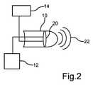
図1は、解析システムを有する自動車16を示す。解析システムは、複数の部品を有している。これらには、超音波センサ10、評価ユニット14、および信号生成ユニット12が含まれる。自動車16は、特に乗用車の形態をとり得る。超音波センサ10は、自動車16の前方領域のみならず、自動車16の後方領域(トランク)にも配置され得る。超音波センサ10は、特に駐車センサの形態をとり得る。このような駐車センサは、好適には自動車16を安全に駐車するために使用される。 FIG. 1 shows an
図2は、超音波センサ10を拡大して概略的に示している。超音波センサ10は、特に超音波22を発信するように設計されている。超音波22は、図2に表示した波線により概略的に示されている。超音波センサ10は、ダイアフラム20を有している。このダイアフラム20は、信号生成ユニット12により励起され得る。つまり、信号生成ユニット12は、ダイアフラム20を振動させることができる。ダイアフラム20の振動により、超音波22が生成され得る。具体的には、信号生成ユニット12は、第1励起信号および第2励起信号を生成することができ、これによりダイアフラム20を励起させることができる。ダイアフラムを励起させるために、アップチャープ信号および/またはダウンチャープ信号が好適に使用される。評価ユニット14は、特にダイアフラム20のたわみを測定するように設計されている。多くの場合、ダイアフラムのたわみは、電圧または電圧信号の形態で記録される。図3は、一例として、第1励起信号29の周波数プロファイル、および第2励起信号31の周波数プロファイルを示している。これら2つの励起信号は、図3において、周波数Fの関数としての電圧プロファイルとして図示されている。本例において、第1電圧プロファイル29は、ダウンチャープ信号により生じたものである。第2励起信号は、これに応じて第2電圧プロファイル31により表される。x軸は周波数Fを表し、y軸は電圧Uを表す。所定の周波数範囲F’について、第1および第2電圧プロファイルの第1最大値M1および第2最大値M2が含まれている。これら2つの最大値M1、M2は、それぞれシフトされている。第1最大値M1は方向R1に沿ってシフトされ、第2最大値M2は方向R2に沿ってシフトされている。それぞれのシフト量は同一である。これは、シフト方向R1がシフト方向R2と同じ長さを有していることを意味する。 FIG. 2 is an enlarged schematic view of an
したがって、2つの最大値M1およびM2は、互いに対して同じ量だけシフトされている。好適には、これら2つの最大値は、一点で合流するようにシフトされる。これにより、好適には、最大値が単一の点で一致するシフトさせた電圧ファイルが得られる。本例において、第1最大値M1は右にシフトされ、第2最大値M2は左にシフトされる。図3の例において、2つの方向R1およびR2は水平である。これらのシフトにより、2つの新しいシフトさせた電圧プロファイル29’、31’がもたらされる。これら2つのシフトさせた電圧プロファイルは、新たな第3電圧プロファイル30に変換することができる。第3電圧プロファイル30は、シフトさせた第1電圧プロファイル29’とシフトさせた第2電圧プロファイル31’との間で延びる。明瞭性を期して、関連するシフトさせた電圧プロファイルは、図3に完全に示していない。具体的には、第3電圧プロファイル30は、これら2つのシフトさせた電圧プロファイルから平均化によって決定される。 Therefore, the two maximum values M1 and M2 are shifted by the same amount with respect to each other. Preferably, these two maximums are shifted to meet at one point. This preferably results in a shifted voltage file where the maximum values match at a single point. In this example, the first maximum value M1 is shifted to the right and the second maximum value M2 is shifted to the left. In the example of FIG. 3, the two directions R1 and R2 are horizontal. These shifts result in two new shifted voltage profiles 29', 31'. These two shifted voltage profiles can be converted into a new
この第3電圧プロファイル30を図4に示す。第3電圧プロファイル30は、周波数Fに対する電圧プロファイルとしてプロットされている。次いで、この第3電圧プロファイル30を使用して、ダイアフラム20の状態を判定する。これには様々な可能性がある。 The
最もシンプルなケースでは、第3電圧プロファイル30の共振周波数が決定される。これは、特に所定の周波数範囲F’における第3電圧プロファイル30の最小値である。この共振周波数を、所定の共振周波数と比較することができる。所定の共振周波数は、ダイアフラム20の予め定義された状態、または定義された状態に関する。ダイアフラム20のこれらの所定の状態には、例えば、ダイアフラム20が氷で覆われていること、または汚れていることが含まれ得る。しかしながら、これらの所定の状態が、ダイアフラム20の温度、またはダイアフラム20の損傷を意味することも可能である。しかしながら、ダイアフラム20の状態を判定するために、共振周波数を決定することに代えて、ダイアフラム20の連続励起モデルを使用することもできる。例えば、式1がこの目的に使用される。式1に記載された電気的パラメータは、第3電圧プロファイル30がシミュレーションされるように、適合または調整される。種々の最適化アルゴリズムがこの目的のために使用され得る。例えば、Nelder-Mead法またはGauss-Newton法を使用して、それぞれの電気的パラメータを決定することができる。電気的パラメータが決定されたら、これらを所定の基準パラメータと比較することができる。この目的のために、厳密に1つの基準パラメータが比較のために選択され得る。原則として、これは、所定の基準パラメータから最大の偏差を呈するパラメータとする。 In the simplest case, the resonant frequency of the
ただし、すべての電気的パラメータとすべての所定の電気的パラメータとの間のユークリッド距離を決定することも想定され得る。具体的には、各ケースについて距離の二乗を計算することが想定され得る。これにより、対向する偏差が合計で0になることを防止することができる。このようにしないと、結果が歪むことがある。理想的には、ダイアフラムの様々な所定の状態に関する複数の基準パラメータを有するデータベースが存在する。データベースが十分に大きければ、ダイアフラムの状態について、単なる状態の判定に加えて、さらに定量的に判定することができる。例えば、ダイアフラム20がどれくらい汚れているか、またはダイアフラム20がどれくらいの氷で覆われているかを判定することができる。超音波センサのダイアフラム20に付着した氷の層の厚さを測定することができる。 However, it can also be envisioned to determine the Euclidean distance between all electrical parameters and all given electrical parameters. Specifically, it can be envisioned to calculate the square of the distance for each case. This makes it possible to prevent the opposite deviations from becoming 0 in total. Otherwise, the results may be distorted. Ideally, there is a database with multiple reference parameters for various predetermined states of the diaphragm. If the database is large enough, the state of the diaphragm can be determined more quantitatively, in addition to simply determining the state. For example, it can be determined how dirty the
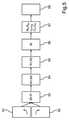
図5は、一例として、本方法のいくつかのステップの概要を示している。ステップS1およびステップS2において、ダイアフラム20は、それぞれアップチャープ信号およびダウンチャープ信号により励起される。アップチャープ信号を、上方に湾曲した矢印で示す。これに対応して、下方に湾曲した矢印は、ダウンチャープ信号を表す。これら2つの励起信号に基づいて、ステップ3において、ダイアフラム20は、励起され振動する。具体的には、第1励起信号が、第2励起信号の前に生成されることが想定され得る。したがって、ダイアフラム20は、好適には2つの励起信号によって同時に励起されない。ダイアフラム20のこれらの励起に基づいて、2つの異なる電圧プロファイルが、ステップS3で測定され得る。 FIG. 5 outlines some steps of the method, as an example. In step S1 and step S2, the
ステップS4において、図3に示すように、2つの最大値M1およびM2の位置が決定され得る。これは、単純で一般的なアルゴリズムを用いて実施され得る。具体的には、これら2つの最大値M1およびM2は、第1電圧プロファイル29および第2電圧プロファイル31の導関数がゼロとなる点である。 In step S4, the positions of the two maximum values M1 and M2 can be determined, as shown in FIG. This can be done using a simple and general algorithm. Specifically, these two maximum values M1 and M2 are points where the derivative of the
ステップS5において、2つの最大値の位置が同一量だけシフトされる。2つのシフト方向は互いに反対である。特に、第1方向R1は、水平で右を向いていてもよい。これに対応して、第2方向Rも水平で左を向いて配向される。 In step S5, the positions of the two maximum values are shifted by the same amount. The two shift directions are opposite to each other. In particular, the first direction R1 may be horizontal and facing right. Correspondingly, the second direction R is also oriented horizontally and facing left.
第3電圧プロファイル30がステップS6で決定される。好適には、これは、シフトさせた電圧プロファイル29’および31’を平均化することにより実施される。平均化は、元の第1電圧プロファイル29および元の第2電圧プロファイル31に関するものではないことに留意されたい。第3電圧プロファイル30は、好適には、シフトさせた第1電圧プロファイル29’およびシフトさせた第2電圧プロファイル31’に基づいて決定される。明瞭性を期して、これら2つの電圧プロファイルは、図3において29’および31’のみでそれぞれ示す。 The
ステップS7において、連続ダイアフラム励起モデルの電気的パラメータが決定され得る。例えば、式1がこの目的のために使用される。それぞれの電気的パラメータは、数学的最適アルゴリズムを使用して決定することができる。これらの決定された電気的パラメータを所定の基準パラメータと比較することにより、ダイアフラム20の状態を正確に判定することができる。こうして、ダイアフラム20のブロック状態が検出され得る。しかしながら、ダイアフラム20の温度や、ダイアフラム20を覆う氷の程度等の他の状態も判定することができる。 In step S7, the electrical parameters of the continuous diaphragm excitation model can be determined. For example,
電気的パラメータを利用することにより、ダイアフラム20の種々の状態を検出することができるだけでなく、ダイアフラム20の連続励起モデルによってセンサの挙動を説明することもできる。このセンサの挙動は、例えば、超音波センサ10のレベル変動を補償するように、あるいは温度補償を可能にするように利用され得る。 Not only can various states of the
Claims (15)
Translated fromJapanesea)所定の第1周波数プロファイルにある第1励起信号(29)を、前記超音波センサ(10)の前記ダイアフラム(20)に印加するステップと、
b)前記第1励起信号により生じた第1電圧プロファイル(29)を、前記第1励起信号の周波数(F)の関数として測定するステップと、
を実施し、
さらに、
c)前記第1周波数プロファイルと異なる所定の第2周波数プロファイルを有する第2励起信号を、前記超音波センサ(10)の前記ダイアフラム(20)に印加するステップと、
d)前記第2励起信号により生じた第2電圧プロファイル(31)を、前記第2励起信号の周波数(F)の関数として測定するステップと、
e)前記第1電圧プロファイル(29)を第1方向(R1)に一定量だけシフトさせるとともに、前記第2電圧プロファイル(31)を第2方向(R2)に同量だけシフトさせることで、2つの前記電圧プロファイルの最大値(M1、M2)のそれぞれの位置を、所定の周波数範囲において互いにマッチさせるステップと、
f)ステップe)からの前記第1電圧プロファイル(29)と前記第2電圧プロファイル(31)との間で延びる第3電圧プロファイル(30)を決定するステップと、
g)前記ダイアフラム(20)の連続励起モデルの少なくとも1つの電気的パラメータを決定し、少なくとも1つのパラメータを少なくとも1つの所定の基準パラメータと比較することにより、前記ダイアフラム(20)の状態を判定するステップと、
を特徴とする方法。A method for determining a state of a diaphragm (20) of an ultrasonic sensor (10) during operation of an ultrasonic sensor (10).
a) A step of applying a first excitation signal (29) in a predetermined first frequency profile to the diaphragm (20) of the ultrasonic sensor (10).
b) A step of measuring the first voltage profile (29) generated by the first excitation signal as a function of the frequency (F) of the first excitation signal.
And carry out
Moreover,
c) A step of applying a second excitation signal having a predetermined second frequency profile different from the first frequency profile to the diaphragm (20) of the ultrasonic sensor (10).
d) A step of measuring the second voltage profile (31) generated by the second excitation signal as a function of the frequency (F) of the second excitation signal.
e) By shifting the first voltage profile (29) in the first direction (R1) by a certain amount and shifting the second voltage profile (31) in the second direction (R2) by the same amount, 2 A step of matching the positions of the maximum values (M1, M2) of the two voltage profiles with each other in a predetermined frequency range.
f) A step of determining a third voltage profile (30) extending between the first voltage profile (29) and the second voltage profile (31) from step e).
g) The state of the diaphragm (20) is determined by determining at least one electrical parameter of the continuous excitation model of the diaphragm (20) and comparing the at least one parameter with at least one predetermined reference parameter. Steps and
A method characterized by.
請求項1に記載の方法。The first excitation signal (29) takes the form of a down chirp signal, and the second excitation signal (31) takes the form of an up chirp signal.
The method according to claim 1.
請求項1または2に記載の方法。The state of the diaphragm (20) is additionally or alternatively compared with the resonant frequency of the third voltage profile (30) as at least one of the parameters and the predetermined resonant frequency as the predetermined reference parameter. Judgment based on,
The method according to claim 1 or 2.
請求項1または2に記載の方法。The continuous excitation model of the diaphragm (20) includes, as the electrical parameters of the model, a first resistance (Rp ), a first inductance (Lp ), and a first capacitance (Cp ) in a parallel circuit. It has a second resistance (Rs ), a second inductance (Ls ), and a second capacitance (Cs ) in a series circuit.
The method according to claim 1 or 2.
前記ダイアフラム(20)の状態を判定するために、前記モデルの厳密に1つの電気的パラメータであって、その対応する基準パラメータから最大の偏差を有する電気的パラメータが、対応する前記基準パラメータと比較される、
請求項1~4の一項に記載の方法。Reference parameters are predefined for a given state of the diaphragm (20).
To determine the state of the diaphragm (20), an electrical parameter that is exactly one electrical parameter of the model and has the largest deviation from its corresponding reference parameter is compared to the corresponding reference parameter. Be done,
The method according to claim 1-4.
請求項5に記載の方法。The predetermined state of the diaphragm (20) means that the diaphragm (20) is covered with ice or contaminants.
The method according to claim 5.
請求項5に記載の方法。The predetermined state of the diaphragm (20) means the temperature of the diaphragm (20).
The method according to claim 5.
請求項1~7の一項に記載の方法。In order to quantitatively determine the state of the diaphragm (20), the degree of coverage and / or the degree of contamination of the diaphragm (20) is measured based on at least one determined electrical parameter. Ru,
The method according to claim 1.
請求項1~8の一項に記載の方法。If the diaphragm (20) is damaged or dirty, a warning signal will be generated.
The method according to claim 1.
請求項1~9の一項に記載の方法。The third voltage profile (30) is determined in step f) by averaging the first and second voltage profiles (29, 31).
The method according to claim 1.
請求項1~10の一項に記載の方法。In step e), when the voltage profile (29, 31) is shifted, the first direction (R1) is opposite to the second direction (R2).
The method according to claim 1-10.
-前記超音波センサ(20)の前記ダイアフラム(20)を励起するための第1励起信号(29)および第2励起信号(31)を生成するための信号生成ユニット(12)と、
-請求項1~11の一項に記載の方法を実施するように設計された評価ユニット(14)と、
を有する自動車(16)用の解析システム。-Ultrasonic sensors (10) with diaphragms (20) and
-A signal generation unit (12) for generating a first excitation signal (29) and a second excitation signal (31) for exciting the diaphragm (20) of the ultrasonic sensor (20).
-The evaluation unit (14) designed to carry out the method according to claim 1-11, and the evaluation unit (14).
Analysis system for automobiles (16).
請求項12に記載の解析システム。The first excitation signal (29) takes the form of a down chirp signal, and the second excitation signal (31) takes the form of an up chirp signal.
The analysis system according to claim 12.
Applications Claiming Priority (3)
| Application Number | Priority Date | Filing Date | Title |
|---|---|---|---|
| DE102018129044.6 | 2018-11-19 | ||
| DE102018129044.6ADE102018129044A1 (en) | 2018-11-19 | 2018-11-19 | Method and analysis system for determining a state of a membrane of an ultrasonic sensor |
| PCT/EP2019/080457WO2020104195A1 (en) | 2018-11-19 | 2019-11-07 | Method and analysis system for determining a state of a diaphragm of an ultrasound sensor |
Publications (2)
| Publication Number | Publication Date |
|---|---|
| JP2022507748Atrue JP2022507748A (en) | 2022-01-18 |
| JP7209834B2 JP7209834B2 (en) | 2023-01-20 |
Family
ID=68536823
Family Applications (1)
| Application Number | Title | Priority Date | Filing Date |
|---|---|---|---|
| JP2021527231AActiveJP7209834B2 (en) | 2018-11-19 | 2019-11-07 | Method and system for determining the state of a diaphragm of an ultrasonic sensor |
Country Status (7)
| Country | Link |
|---|---|
| US (1) | US12000966B2 (en) |
| EP (1) | EP3884296A1 (en) |
| JP (1) | JP7209834B2 (en) |
| KR (1) | KR102568043B1 (en) |
| CN (1) | CN113272680B (en) |
| DE (1) | DE102018129044A1 (en) |
| WO (1) | WO2020104195A1 (en) |
Families Citing this family (1)
| Publication number | Priority date | Publication date | Assignee | Title |
|---|---|---|---|---|
| DE102019101323A1 (en)* | 2019-01-18 | 2020-07-23 | Wabco Gmbh | Air spring |
Citations (6)
| Publication number | Priority date | Publication date | Assignee | Title |
|---|---|---|---|---|
| WO2015025527A1 (en)* | 2013-08-23 | 2015-02-26 | パナソニックIpマネジメント株式会社 | Object detection device for vehicle |
| WO2017148633A1 (en)* | 2016-02-29 | 2017-09-08 | Valeo Schalter Und Sensoren Gmbh | Filter device for filtering a supply voltage of an ultrasonic sensor of a motor vehicle, ultrasonic sensor device, and motor vehicle |
| JP2018054580A (en)* | 2016-09-30 | 2018-04-05 | パナソニックIpマネジメント株式会社 | Detection apparatus, detection method, and detection program |
| WO2018139193A1 (en)* | 2017-01-25 | 2018-08-02 | 株式会社村田製作所 | Ultrasonic device |
| WO2018162659A1 (en)* | 2017-03-09 | 2018-09-13 | Valeo Schalter Und Sensoren Gmbh | Method for determining the functional state of an ultrasonic sensor using a transmission function of the ultrasonic sensor, ultrasonic sensor device, and motor vehicle |
| JPWO2018139192A1 (en)* | 2017-01-25 | 2019-08-08 | 株式会社村田製作所 | Ultrasonic device |
Family Cites Families (32)
| Publication number | Priority date | Publication date | Assignee | Title |
|---|---|---|---|---|
| JPH06232232A (en)* | 1992-01-27 | 1994-08-19 | U C Japan Kk | Method and apparatus for evaluating ultrasonic wire bonding |
| AR016812A1 (en) | 1997-08-14 | 2001-08-01 | Samsung Electronics Co Ltd | METHOD FOR TRANSMITTING COMPRESSED VIDEO INFORMATION, COMPRESSION AND VIDEO RECORDING PROVISIONS AND VIDEO PLAYBACK |
| US6314380B1 (en) | 1999-06-03 | 2001-11-06 | Robert Bosch Corporation Corp Of Delaware | Ultrasound transducer temperature compensation methods, apparatus and programs |
| DE102004016267A1 (en) | 2004-04-02 | 2005-10-20 | Bosch Gmbh Robert | Method for temperature-independent distance measurement |
| DE102005057973B4 (en) | 2005-12-05 | 2017-02-23 | Robert Bosch Gmbh | Method for functional testing of an ultrasonic sensor and distance measuring device |
| DE102007059908A1 (en)* | 2007-12-12 | 2009-06-18 | Robert Bosch Gmbh | Sensor function for controlling with variable transmission frequency for the purpose of detecting soiling |
| DE102009039083B4 (en) | 2009-08-27 | 2020-06-18 | Valeo Schalter Und Sensoren Gmbh | Method and arrangement for determining the ambient temperature of an ultrasonic sensor |
| DE102009040992B4 (en) | 2009-09-10 | 2015-11-26 | Valeo Schalter Und Sensoren Gmbh | Method for icing and contamination detection of ultrasonic sensors |
| ES2656222T3 (en) | 2011-02-17 | 2018-02-26 | Qualcomm Incorporated | A procedure and a system for determining a cardiovascular magnitude of a mammal |
| DE102011075113A1 (en)* | 2011-05-03 | 2012-11-08 | Endress + Hauser Gmbh + Co. Kg | Apparatus and method for operating a device for determining and / or monitoring at least one physical process variable |
| DE102012200716A1 (en)* | 2012-01-19 | 2013-07-25 | Robert Bosch Gmbh | Method for determining the position and / or movement of objects in the vicinity of a movement aid by means of sound signals and device for carrying out the method |
| DE102012000948A1 (en)* | 2012-01-19 | 2013-07-25 | Valeo Schalter Und Sensoren Gmbh | Method for detecting an iced and / or soiled state of an ultrasonic sensor in a motor vehicle, sensor device and motor vehicle |
| DE102012002979A1 (en)* | 2012-02-15 | 2013-08-22 | Valeo Schalter Und Sensoren Gmbh | Driver assistance device with an ultrasonic sensor, motor vehicle and method for operating an ultrasonic sensor |
| US8676438B2 (en) | 2012-07-31 | 2014-03-18 | Ford Global Technologies | Method and system for implementing ultrasonic sensor signal strength calibrations |
| DE102012216968A1 (en)* | 2012-09-21 | 2014-04-17 | Robert Bosch Gmbh | Method for evaluation adaptation and functional testing of an ultrasonic sensor and a corresponding ultrasonic sensor |
| JP6073646B2 (en) | 2012-10-29 | 2017-02-01 | 株式会社デンソー | Correction value setting device and distance detection device |
| KR101611446B1 (en)* | 2013-02-28 | 2016-04-26 | 삼성메디슨 주식회사 | Ultrasonic diagnose apparatus and method using the same |
| US9648432B2 (en)* | 2013-07-23 | 2017-05-09 | Analog Devices Global | Method of controlling sound reproduction of enclosure mounted loudspeakers |
| DE102013015410A1 (en) | 2013-09-17 | 2015-03-19 | Valeo Schalter Und Sensoren Gmbh | Method for detecting a blocked state of an ultrasonic sensor Ultrasonic sensor device and motor vehicle |
| DE102014201482A1 (en)* | 2014-01-28 | 2015-07-30 | Robert Bosch Gmbh | Method and device for detecting a malfunction of an ultrasonic transducer by evaluating an impedance envelope |
| DE102014113601B4 (en)* | 2014-09-19 | 2016-06-30 | Valeo Schalter Und Sensoren Gmbh | A method for detecting a blocked state of an ultrasonic sensor, ultrasonic sensor device and motor vehicle |
| CN104750978A (en)* | 2015-03-12 | 2015-07-01 | 华中科技大学 | Beam member damage recognition method based on antiresonant frequency and particle swarm optimization |
| DE102015224733B3 (en)* | 2015-12-09 | 2016-10-20 | Robert Bosch Gmbh | Method and device for detecting an ice-covered electroacoustic sensor |
| CN105916079B (en)* | 2016-06-07 | 2019-09-13 | 瑞声科技(新加坡)有限公司 | A kind of nonlinear loudspeaker compensation method and device |
| CN206097107U (en)* | 2016-07-08 | 2017-04-12 | 山东威瑞外科医用制品有限公司 | Ultrasonic knife frequency tracking device |
| DE102016222810A1 (en)* | 2016-11-18 | 2018-05-24 | Robert Bosch Gmbh | Method for operating an ultrasound system |
| CN108654967B (en)* | 2017-03-29 | 2020-09-22 | 重庆西山科技股份有限公司 | Ultrasonic transducer resonant frequency detection method and device and ultrasonic transducer |
| CN108007557A (en)* | 2017-11-22 | 2018-05-08 | 锐泰安医疗科技(苏州)有限公司 | A kind of method and apparatus of lookup resonant frequency point for transducer |
| DE102017128837A1 (en)* | 2017-12-05 | 2019-06-06 | Valeo Schalter Und Sensoren Gmbh | Method for determining a functional state of an ultrasound sensor, wherein a voltage is detected, and ultrasound sensor device with an ultrasound sensor |
| CN108307284A (en)* | 2017-12-29 | 2018-07-20 | 青岛海信移动通信技术股份有限公司 | A kind of method, device and mobile terminal of automatic detection loud speaker |
| DE102018119266B3 (en) | 2018-08-08 | 2019-09-12 | Valeo Schalter Und Sensoren Gmbh | Method for operating an ultrasonic sensor by excitation with a frequency-coded signal, computer program product and ultrasound sensor |
| DE102018124024A1 (en)* | 2018-09-28 | 2020-04-02 | Valeo Schalter Und Sensoren Gmbh | Method for operating an ultrasonic sensor of a vehicle with reduced diagnosis in a measuring operation of the ultrasonic sensor, and ultrasonic sensor device |
- 2018
- 2018-11-19DEDE102018129044.6Apatent/DE102018129044A1/enactivePending
- 2019
- 2019-11-07EPEP19801813.7Apatent/EP3884296A1/enactivePending
- 2019-11-07USUS17/294,870patent/US12000966B2/enactiveActive
- 2019-11-07WOPCT/EP2019/080457patent/WO2020104195A1/ennot_activeCeased
- 2019-11-07JPJP2021527231Apatent/JP7209834B2/enactiveActive
- 2019-11-07KRKR1020217018895Apatent/KR102568043B1/enactiveActive
- 2019-11-07CNCN201980087108.XApatent/CN113272680B/enactiveActive
Patent Citations (6)
| Publication number | Priority date | Publication date | Assignee | Title |
|---|---|---|---|---|
| WO2015025527A1 (en)* | 2013-08-23 | 2015-02-26 | パナソニックIpマネジメント株式会社 | Object detection device for vehicle |
| WO2017148633A1 (en)* | 2016-02-29 | 2017-09-08 | Valeo Schalter Und Sensoren Gmbh | Filter device for filtering a supply voltage of an ultrasonic sensor of a motor vehicle, ultrasonic sensor device, and motor vehicle |
| JP2018054580A (en)* | 2016-09-30 | 2018-04-05 | パナソニックIpマネジメント株式会社 | Detection apparatus, detection method, and detection program |
| WO2018139193A1 (en)* | 2017-01-25 | 2018-08-02 | 株式会社村田製作所 | Ultrasonic device |
| JPWO2018139192A1 (en)* | 2017-01-25 | 2019-08-08 | 株式会社村田製作所 | Ultrasonic device |
| WO2018162659A1 (en)* | 2017-03-09 | 2018-09-13 | Valeo Schalter Und Sensoren Gmbh | Method for determining the functional state of an ultrasonic sensor using a transmission function of the ultrasonic sensor, ultrasonic sensor device, and motor vehicle |
Also Published As
| Publication number | Publication date |
|---|---|
| JP7209834B2 (en) | 2023-01-20 |
| KR20210093315A (en) | 2021-07-27 |
| US12000966B2 (en) | 2024-06-04 |
| CN113272680B (en) | 2024-05-03 |
| EP3884296A1 (en) | 2021-09-29 |
| KR102568043B1 (en) | 2023-08-17 |
| WO2020104195A1 (en) | 2020-05-28 |
| US20220011419A1 (en) | 2022-01-13 |
| DE102018129044A1 (en) | 2020-05-20 |
| CN113272680A (en) | 2021-08-17 |
Similar Documents
| Publication | Publication Date | Title |
|---|---|---|
| CN104808195B (en) | Method and apparatus for identifying the failure of ultrasonic transducer by analysis processing impedance envelope | |
| US7487059B2 (en) | Transducer health diagnostics for structural health monitoring (SHM) systems | |
| Raghavan et al. | Guided-wave signal processing using chirplet matching pursuits and mode correlation forstructural health monitoring | |
| US8036836B2 (en) | Dynamic environmental change compensation of sensor data in structural health monitoring systems | |
| JP7439105B2 (en) | Calibration device and method for multi-input-multi-output radar sensor | |
| US7426447B2 (en) | Method and system for monitoring structural damage | |
| US10816436B2 (en) | System for temperature insensitive damage detection | |
| KR102546876B1 (en) | Method for operating an ultrasonic sensor apparatus for a motor vehicle with adaptation of a temporal profile of an amplitude in frequency-modulated excitation signals | |
| JP2010502966A (en) | Method and apparatus for monitoring sensor noise | |
| CN109959519A (en) | Method for noise testing of vehicles on test sections | |
| US20240183753A1 (en) | Method and vehicle system for determining the state of the components of a chassis | |
| JP2022507748A (en) | Methods and systems for determining the state of ultrasonic sensor diaphragms | |
| KR102645272B1 (en) | Method and ultrasonic sensor device for operating an ultrasonic sensor in a vehicle using reduced diagnosis in the measurement mode of the ultrasonic sensor | |
| David et al. | Detection of road pavement quality using statistical clustering methods | |
| Dias et al. | An enhanced approach for damage detection using the electromechanical impedance with temperature effects compensation | |
| US6647324B2 (en) | Method for digitally filtering a signal burdened with noise and a control system for a vehicle | |
| KR102061616B1 (en) | Diagnosis method of structure and diagnosis system using nonlinear spectral correlation | |
| US20240036194A1 (en) | Ultrasonic sensor system for a motor vehicle and method for operating the ultrasonic sensor system | |
| Ma et al. | State-of-the-art of terrain profile characterisation models | |
| Altmann et al. | Theoretical development of localized pseudo damage | |
| JP2022016127A (en) | Object detection device | |
| Jürgens et al. | Can I trust my TPA results? | |
| US20240230869A1 (en) | Method for determining a function state of an ultrasonic sensor for a vehicle | |
| Patil et al. | Experimental observations in tire cavity resonance and interactions with periodic noise components | |
| CN117633466A (en) | Structural local defect diagnosis and growth rate prediction method, device, computing equipment and storage medium |
Legal Events
| Date | Code | Title | Description |
|---|---|---|---|
| A621 | Written request for application examination | Free format text:JAPANESE INTERMEDIATE CODE: A621 Effective date:20210709 | |
| A977 | Report on retrieval | Free format text:JAPANESE INTERMEDIATE CODE: A971007 Effective date:20220531 | |
| A131 | Notification of reasons for refusal | Free format text:JAPANESE INTERMEDIATE CODE: A131 Effective date:20220607 | |
| A521 | Request for written amendment filed | Free format text:JAPANESE INTERMEDIATE CODE: A523 Effective date:20220822 | |
| TRDD | Decision of grant or rejection written | ||
| A01 | Written decision to grant a patent or to grant a registration (utility model) | Free format text:JAPANESE INTERMEDIATE CODE: A01 Effective date:20221209 | |
| A61 | First payment of annual fees (during grant procedure) | Free format text:JAPANESE INTERMEDIATE CODE: A61 Effective date:20230110 | |
| R150 | Certificate of patent or registration of utility model | Ref document number:7209834 Country of ref document:JP Free format text:JAPANESE INTERMEDIATE CODE: R150 |