JP2022505286A - Dispenser and complementary vaporizer - Google Patents
Dispenser and complementary vaporizerDownload PDFInfo
- Publication number
- JP2022505286A JP2022505286AJP2021521255AJP2021521255AJP2022505286AJP 2022505286 AJP2022505286 AJP 2022505286AJP 2021521255 AJP2021521255 AJP 2021521255AJP 2021521255 AJP2021521255 AJP 2021521255AJP 2022505286 AJP2022505286 AJP 2022505286A
- Authority
- JP
- Japan
- Prior art keywords
- solid
- dispenser
- vaporizer
- opening
- lid
- Prior art date
- Legal status (The legal status is an assumption and is not a legal conclusion. Google has not performed a legal analysis and makes no representation as to the accuracy of the status listed.)
- Withdrawn
Links
Images


Classifications
- A—HUMAN NECESSITIES
- A61—MEDICAL OR VETERINARY SCIENCE; HYGIENE
- A61M—DEVICES FOR INTRODUCING MEDIA INTO, OR ONTO, THE BODY; DEVICES FOR TRANSDUCING BODY MEDIA OR FOR TAKING MEDIA FROM THE BODY; DEVICES FOR PRODUCING OR ENDING SLEEP OR STUPOR
- A61M11/00—Sprayers or atomisers specially adapted for therapeutic purposes
- A61M11/04—Sprayers or atomisers specially adapted for therapeutic purposes operated by the vapour pressure of the liquid to be sprayed or atomised
- A61M11/041—Sprayers or atomisers specially adapted for therapeutic purposes operated by the vapour pressure of the liquid to be sprayed or atomised using heaters
- A61M11/042—Sprayers or atomisers specially adapted for therapeutic purposes operated by the vapour pressure of the liquid to be sprayed or atomised using heaters electrical
- A—HUMAN NECESSITIES
- A24—TOBACCO; CIGARS; CIGARETTES; SIMULATED SMOKING DEVICES; SMOKERS' REQUISITES
- A24F—SMOKERS' REQUISITES; MATCH BOXES; SIMULATED SMOKING DEVICES
- A24F15/00—Receptacles or boxes specially adapted for cigars, cigarettes, simulated smoking devices or cigarettes therefor
- A24F15/01—Receptacles or boxes specially adapted for cigars, cigarettes, simulated smoking devices or cigarettes therefor specially adapted for simulated smoking devices or cigarettes therefor
- A—HUMAN NECESSITIES
- A24—TOBACCO; CIGARS; CIGARETTES; SIMULATED SMOKING DEVICES; SMOKERS' REQUISITES
- A24F—SMOKERS' REQUISITES; MATCH BOXES; SIMULATED SMOKING DEVICES
- A24F15/00—Receptacles or boxes specially adapted for cigars, cigarettes, simulated smoking devices or cigarettes therefor
- A24F15/12—Receptacles or boxes specially adapted for cigars, cigarettes, simulated smoking devices or cigarettes therefor for pocket use
- A24F15/14—Receptacles or boxes specially adapted for cigars, cigarettes, simulated smoking devices or cigarettes therefor for pocket use with appliances for releasing a single cigar or cigarette
- A—HUMAN NECESSITIES
- A24—TOBACCO; CIGARS; CIGARETTES; SIMULATED SMOKING DEVICES; SMOKERS' REQUISITES
- A24F—SMOKERS' REQUISITES; MATCH BOXES; SIMULATED SMOKING DEVICES
- A24F15/00—Receptacles or boxes specially adapted for cigars, cigarettes, simulated smoking devices or cigarettes therefor
- A24F15/12—Receptacles or boxes specially adapted for cigars, cigarettes, simulated smoking devices or cigarettes therefor for pocket use
- A24F15/16—Receptacles or boxes specially adapted for cigars, cigarettes, simulated smoking devices or cigarettes therefor for pocket use with means for offering
- A—HUMAN NECESSITIES
- A24—TOBACCO; CIGARS; CIGARETTES; SIMULATED SMOKING DEVICES; SMOKERS' REQUISITES
- A24F—SMOKERS' REQUISITES; MATCH BOXES; SIMULATED SMOKING DEVICES
- A24F40/00—Electrically operated smoking devices; Component parts thereof; Manufacture thereof; Maintenance or testing thereof; Charging means specially adapted therefor
- A24F40/20—Devices using solid inhalable precursors
- A—HUMAN NECESSITIES
- A24—TOBACCO; CIGARS; CIGARETTES; SIMULATED SMOKING DEVICES; SMOKERS' REQUISITES
- A24F—SMOKERS' REQUISITES; MATCH BOXES; SIMULATED SMOKING DEVICES
- A24F40/00—Electrically operated smoking devices; Component parts thereof; Manufacture thereof; Maintenance or testing thereof; Charging means specially adapted therefor
- A24F40/40—Constructional details, e.g. connection of cartridges and battery parts
- A24F40/46—Shape or structure of electric heating means
- A—HUMAN NECESSITIES
- A24—TOBACCO; CIGARS; CIGARETTES; SIMULATED SMOKING DEVICES; SMOKERS' REQUISITES
- A24F—SMOKERS' REQUISITES; MATCH BOXES; SIMULATED SMOKING DEVICES
- A24F40/00—Electrically operated smoking devices; Component parts thereof; Manufacture thereof; Maintenance or testing thereof; Charging means specially adapted therefor
- A24F40/50—Control or monitoring
- A24F40/51—Arrangement of sensors
- A—HUMAN NECESSITIES
- A24—TOBACCO; CIGARS; CIGARETTES; SIMULATED SMOKING DEVICES; SMOKERS' REQUISITES
- A24F—SMOKERS' REQUISITES; MATCH BOXES; SIMULATED SMOKING DEVICES
- A24F40/00—Electrically operated smoking devices; Component parts thereof; Manufacture thereof; Maintenance or testing thereof; Charging means specially adapted therefor
- A24F40/50—Control or monitoring
- A24F40/53—Monitoring, e.g. fault detection
- A—HUMAN NECESSITIES
- A61—MEDICAL OR VETERINARY SCIENCE; HYGIENE
- A61M—DEVICES FOR INTRODUCING MEDIA INTO, OR ONTO, THE BODY; DEVICES FOR TRANSDUCING BODY MEDIA OR FOR TAKING MEDIA FROM THE BODY; DEVICES FOR PRODUCING OR ENDING SLEEP OR STUPOR
- A61M15/00—Inhalators
- A61M15/0028—Inhalators using prepacked dosages, one for each application, e.g. capsules to be perforated or broken-up
- A61M15/0045—Inhalators using prepacked dosages, one for each application, e.g. capsules to be perforated or broken-up using multiple prepacked dosages on a same carrier, e.g. blisters
- A—HUMAN NECESSITIES
- A61—MEDICAL OR VETERINARY SCIENCE; HYGIENE
- A61M—DEVICES FOR INTRODUCING MEDIA INTO, OR ONTO, THE BODY; DEVICES FOR TRANSDUCING BODY MEDIA OR FOR TAKING MEDIA FROM THE BODY; DEVICES FOR PRODUCING OR ENDING SLEEP OR STUPOR
- A61M15/00—Inhalators
- A61M15/0028—Inhalators using prepacked dosages, one for each application, e.g. capsules to be perforated or broken-up
- A61M15/0063—Storages for pre-packed dosages
- A—HUMAN NECESSITIES
- A61—MEDICAL OR VETERINARY SCIENCE; HYGIENE
- A61M—DEVICES FOR INTRODUCING MEDIA INTO, OR ONTO, THE BODY; DEVICES FOR TRANSDUCING BODY MEDIA OR FOR TAKING MEDIA FROM THE BODY; DEVICES FOR PRODUCING OR ENDING SLEEP OR STUPOR
- A61M15/00—Inhalators
- A61M15/06—Inhaling appliances shaped like cigars, cigarettes or pipes
- B—PERFORMING OPERATIONS; TRANSPORTING
- B65—CONVEYING; PACKING; STORING; HANDLING THIN OR FILAMENTARY MATERIAL
- B65D—CONTAINERS FOR STORAGE OR TRANSPORT OF ARTICLES OR MATERIALS, e.g. BAGS, BARRELS, BOTTLES, BOXES, CANS, CARTONS, CRATES, DRUMS, JARS, TANKS, HOPPERS, FORWARDING CONTAINERS; ACCESSORIES, CLOSURES, OR FITTINGS THEREFOR; PACKAGING ELEMENTS; PACKAGES
- B65D83/00—Containers or packages with special means for dispensing contents
- B65D83/04—Containers or packages with special means for dispensing contents for dispensing annular, disc-shaped, spherical or like small articles, e.g. tablets or pills
- B65D83/0409—Containers or packages with special means for dispensing contents for dispensing annular, disc-shaped, spherical or like small articles, e.g. tablets or pills the dispensing means being adapted for delivering one article, or a single dose, upon each actuation
- B65D83/0418—Containers or packages with special means for dispensing contents for dispensing annular, disc-shaped, spherical or like small articles, e.g. tablets or pills the dispensing means being adapted for delivering one article, or a single dose, upon each actuation the articles being substantially flat and stacked one upon the other and the dispensing-closing device sliding the article to be dispensed along the flat side of the next article
- A—HUMAN NECESSITIES
- A61—MEDICAL OR VETERINARY SCIENCE; HYGIENE
- A61M—DEVICES FOR INTRODUCING MEDIA INTO, OR ONTO, THE BODY; DEVICES FOR TRANSDUCING BODY MEDIA OR FOR TAKING MEDIA FROM THE BODY; DEVICES FOR PRODUCING OR ENDING SLEEP OR STUPOR
- A61M15/00—Inhalators
- A61M15/0028—Inhalators using prepacked dosages, one for each application, e.g. capsules to be perforated or broken-up
- A61M15/0045—Inhalators using prepacked dosages, one for each application, e.g. capsules to be perforated or broken-up using multiple prepacked dosages on a same carrier, e.g. blisters
- A61M15/0053—Inhalators using prepacked dosages, one for each application, e.g. capsules to be perforated or broken-up using multiple prepacked dosages on a same carrier, e.g. blisters characterized by the type or way of disposal
- A61M15/006—Inhalators using prepacked dosages, one for each application, e.g. capsules to be perforated or broken-up using multiple prepacked dosages on a same carrier, e.g. blisters characterized by the type or way of disposal the used dosages being discarded out of the inhaler's housing
- A—HUMAN NECESSITIES
- A61—MEDICAL OR VETERINARY SCIENCE; HYGIENE
- A61M—DEVICES FOR INTRODUCING MEDIA INTO, OR ONTO, THE BODY; DEVICES FOR TRANSDUCING BODY MEDIA OR FOR TAKING MEDIA FROM THE BODY; DEVICES FOR PRODUCING OR ENDING SLEEP OR STUPOR
- A61M2205/00—General characteristics of the apparatus
- A61M2205/33—Controlling, regulating or measuring
- A61M2205/3306—Optical measuring means
- A—HUMAN NECESSITIES
- A61—MEDICAL OR VETERINARY SCIENCE; HYGIENE
- A61M—DEVICES FOR INTRODUCING MEDIA INTO, OR ONTO, THE BODY; DEVICES FOR TRANSDUCING BODY MEDIA OR FOR TAKING MEDIA FROM THE BODY; DEVICES FOR PRODUCING OR ENDING SLEEP OR STUPOR
- A61M2205/00—General characteristics of the apparatus
- A61M2205/33—Controlling, regulating or measuring
- A61M2205/3317—Electromagnetic, inductive or dielectric measuring means
Landscapes
- Health & Medical Sciences (AREA)
- Engineering & Computer Science (AREA)
- Public Health (AREA)
- Life Sciences & Earth Sciences (AREA)
- Veterinary Medicine (AREA)
- Anesthesiology (AREA)
- Biomedical Technology (AREA)
- Heart & Thoracic Surgery (AREA)
- Hematology (AREA)
- General Health & Medical Sciences (AREA)
- Animal Behavior & Ethology (AREA)
- Bioinformatics & Cheminformatics (AREA)
- Pulmonology (AREA)
- Mechanical Engineering (AREA)
- Disinfection, Sterilisation Or Deodorisation Of Air (AREA)
- Filling Or Discharging Of Gas Storage Vessels (AREA)
- Catching Or Destruction (AREA)
Abstract
Translated fromJapaneseDescription
Translated fromJapanese本発明は、固体又は半固体の気化可能な消耗品を無料の気化器に分配するためのディスペンサに関する。 The present invention relates to a dispenser for distributing solid or semi-solid vaporizable consumables to a free vaporizer.
電子タバコなどのエアロゾル生成デバイスは、比較的よく知られており、従来の喫煙デバイス及び方法に代わるものとして一層人気が高まっている。物質を燃焼させるのではなく、加熱して、吸入のための蒸気を生成するデバイスは、近年、消費者に人気のあるエアロゾル生成デバイスのサブセットとなっている。 Aerosol-generating devices such as e-cigarettes are relatively well known and are becoming more popular as alternatives to traditional smoking devices and methods. Devices that heat rather than burn a substance to produce vapor for inhalation have become a subset of the aerosol-producing devices that are popular with consumers in recent years.
そのようなデバイスの1つは、ユーザがデバイスを起動する、通常、ボタンを押すと、デバイスのチャンバ内に保持された蒸気生成物質を加熱するように電気エネルギーを利用する加熱システムを採用している。物質が加熱されると蒸気が生成され、デバイスは、ユーザが蒸気を吸入できるように構成されている。 One such device employs a heating system that utilizes electrical energy to heat the vapor product material held in the chamber of the device when the user activates the device, usually at the push of a button. There is. When the substance is heated, vapor is generated and the device is configured to allow the user to inhale the vapor.
気化可能な物質がユーザによって消費される、すなわち物質から蒸気をもはや生成することができなくなると、新しい気化可能な物質を消費のためにデバイスに組み込むために、物質は、デバイスから排出されなければならない。 When a vaporizable substance is consumed by the user, i.e. it can no longer generate vapor from the substance, the substance must be ejected from the device in order to incorporate the new vaporizable substance into the device for consumption. It doesn't become.
通常、エアロゾルデバイス及び気化可能な物質は、ユーザの人に運ばれ、デバイスのロード及びアンロードは、手作業で行われる。気化可能な物質に触れることは、ユーザにとって不快であり、これは、加熱するが、燃えないデバイスで使用される気化可能な物質が、通常、気化可能な物質とのユーザの接触を最小限に抑えるために被覆されていることを意味する。これは、洗練された解決策ではなく、通常、エアロゾルデバイスに導入された消耗品の一部(すなわち被覆)が実際には気化可能でないことを意味する。 Usually, the aerosol device and the vaporizable material are carried to the user, and the loading and unloading of the device is done manually. Touching a vaporizable substance is unpleasant to the user, which is that the vaporizable substance used in a device that heats but does not burn usually minimizes the user's contact with the vaporizable substance. It means that it is covered to suppress it. This is not a sophisticated solution and usually means that some (ie, coatings) of the consumables introduced into the aerosol device are not really vaporizable.
エアロゾル生成デバイスの市場での採用が急拡大しているため、ユーザは、エアロゾルデバイスで使用する気化可能な物質を移送するためのより効率的な方法並びにデバイスのロード及びアンロードのための改善された機構を求めている。 Due to the rapid market adoption of aerosol-generating devices, users have improved methods for transporting vaporizable materials used in aerosol devices as well as improved device loading and unloading. We are looking for a mechanism.
本発明は、上述の課題の少なくともいくつかを軽減しようとするものである。 The present invention seeks to alleviate at least some of the above problems.
本発明の第1の態様によれば、固体又は半固体の気化可能な消耗品を気化器に分配するためのディスペンサであって、第1の貯蔵部であって、その中に少なくとも1つの固体又は半固体の気化可能な消耗品を貯蔵するためのものであり、開口部であって、それを通して固体又は半固体の気化可能な消耗品を分配するための開口部を含む第1の貯蔵部と、第1の蓋であって、閉位置にあるときにそれが第1の貯蔵部の開口部を閉じるように配置される第1の蓋とを含むディスペンサが提供される。更に、本発明の第1の態様による前記ディスペンサは、使用時、気化器をディスペンサと係合させることが、第1の貯蔵部の開口部を加熱チャンバの開口部と整列させることにより、第1の貯蔵部内に貯蔵された固体又は半固体の気化可能な消耗品を気化器の加熱チャンバにロードするように配置される。そのような配置を利用することにより、ユーザは、固体又は半固体の気化可能な消耗品を気化器に手でロードする必要がなく、且つ消耗品を被覆する必要もない。 According to the first aspect of the present invention, it is a dispenser for distributing a solid or semi-solid vaporizable consumable to a vaporizer, a first storage portion, and at least one solid in the dispenser. Or a first storage unit for storing semi-solid vaporizable consumables, the opening comprising an opening for distributing solid or semi-solid vaporizable consumables through it. And a dispenser comprising a first lid, which is arranged to close the opening of the first reservoir when in the closed position. Further, in the dispenser according to the first aspect of the present invention, when in use, the vaporizer can be engaged with the dispenser by aligning the opening of the first storage with the opening of the heating chamber. Solid or semi-solid vaporizable consumables stored in the reservoir of the vaporizer are arranged to be loaded into the heating chamber of the vaporizer. By utilizing such an arrangement, the user does not need to manually load the solid or semi-solid vaporizable consumables into the vaporizer and does not need to cover the consumables.
第1の実施形態では、本発明の第1の態様によるディスペンサは、少なくとも1つの固体又は半固体の気化可能な消耗品を貯蔵するための容量を有する第2の貯蔵部を更に含み、好ましくは、第2の貯蔵部は、第1の貯蔵部と少なくとも同じ数の固体又は半固体の気化可能な消耗品を貯蔵するための容量を有する。この実施形態では、第2の貯蔵部は、開口部であって、それを通して固体又は半固体の気化可能な消耗品を受容するための開口部を含み、及びディスペンサは、使用時、気化器の加熱チャンバ内に貯蔵された固体又は半固体の気化可能な消耗品をアンロードするために気化器をディスペンサと係合させることが、第2の貯蔵部の開口部を加熱チャンバの開口部と整列させるように配置される。そのような配置を利用することにより、ユーザは、前記消耗品に直接触れる必要なしに、1つのデバイスにおいて未使用の固体又は半固体の気化可能な消耗品を貯蔵し、且つ使用済みの消耗品を廃棄することができる。 In a first embodiment, the dispenser according to the first aspect of the invention further comprises a second reservoir having a capacity for storing at least one solid or semi-solid vaporizable consumable, preferably. The second reservoir has the capacity to store at least as many solid or semi-solid vaporizable consumables as the first reservoir. In this embodiment, the second reservoir is an opening through which an opening for receiving solid or semi-solid vaporizable consumables is included, and the dispenser, in use, of the vaporizer. Engaging the vaporizer with the dispenser to unload solid or semi-solid vaporizable consumables stored in the heating chamber aligns the opening of the second reservoir with the opening of the heating chamber. Arranged to let. By utilizing such an arrangement, the user can store unused solid or semi-solid vaporizable consumables in one device without having to touch the consumables directly, and used consumables. Can be discarded.
好ましくは、第1の実施形態の第1の貯蔵部及び第2の貯蔵部は、結合され、それにより、第2の貯蔵部の開口部は、第1の貯蔵部の開口部の遠位の結合された貯蔵部の本体の端部にあるる。更に好ましくは、第1の実施形態の結合された貯蔵部は、第1の貯蔵部が未使用の固体又は半固体の気化可能な消耗品で満たされているとき、第1の貯蔵部が第2の貯蔵部よりも大きく、且つ第1の貯蔵部内に未使用の固体又は半固体の気化可能な消耗品がないとき、第2の貯蔵部が第1の貯蔵部よりも大きいように、第1の貯蔵部及び第2の貯蔵部を画定するための可動の仕切りを含む。なおも更に好ましくは、第1の実施形態の結合された貯蔵部は、第1の貯蔵部が未使用の固体又は半固体の気化可能な消耗品で満たされているとき、可動の仕切りが第2の貯蔵部の開口部を閉じ、且つ第1の貯蔵部内に未使用の固体又は半固体の気化可能な消耗品がないとき、可動の仕切りが第1の貯蔵部の開口部を閉じるように、第1の貯蔵部及び第2の貯蔵部を画定するための可動の仕切りを含む。そのような配置により、ユーザに対してディスペンサのかさばりを低減すると同時に、2つの貯蔵部の利点も提供する。 Preferably, the first and second reservoirs of the first embodiment are coupled so that the opening of the second reservoir is distal to the opening of the first reservoir. Located at the end of the body of the combined reservoir. More preferably, the combined reservoir of the first embodiment has a first reservoir when the first reservoir is filled with an unused solid or semi-solid vaporizable consumable. First, the second reservoir is larger than the first reservoir when it is larger than the second reservoir and there are no unused solid or semi-solid vaporizable consumables in the first reservoir. Includes a movable partition to define one reservoir and a second reservoir. Even more preferably, the combined reservoir of the first embodiment has a movable partition when the first reservoir is filled with an unused solid or semi-solid vaporizable consumable. The movable partition closes the opening of the first storage when the opening of the second storage is closed and there are no unused solid or semi-solid vaporizable consumables in the first storage. , Includes a movable partition to define a first reservoir and a second reservoir. Such an arrangement reduces the bulk of the dispenser to the user while also providing the advantages of two reservoirs.
代替的な好ましいアセンブリでは、第1の実施形態の第1の貯蔵部及び第2の貯蔵部は、第1の蓋によって分離される。そのようなアセンブリにより、必要な蓋の数を低減し、ディスペンサの構造を単純化する。 In an alternative preferred assembly, the first and second reservoirs of the first embodiment are separated by a first lid. Such an assembly reduces the number of lids required and simplifies the structure of the dispenser.
第2の実施形態では、本発明の第1の態様によるディスペンサは、開口部であって、それを通して固体又は半固体の気化可能な消耗品を排出するための開口部を更に含む。この実施形態では、ディスペンサは、使用時、気化器の加熱チャンバ内に貯蔵された固体又は半固体の気化可能な消耗品をアンロードするために気化器をディスペンサと係合させることが、ディスペンサの開口部を加熱チャンバの開口部と整列させるように配置される。そのような配置により、使用済みの固体又は半固体の気化可能な消耗品を、前記消耗品に直接触れる必要なしに廃棄し、且つ貯蔵しないことを可能にする。 In a second embodiment, the dispenser according to the first aspect of the invention further comprises an opening through which a solid or semi-solid vaporizable consumable is discharged. In this embodiment, the dispenser is capable of engaging the vaporizer with the dispenser to unload solid or semi-solid vaporizable consumables stored in the vaporizer's heating chamber during use. The openings are arranged to align with the openings in the heating chamber. Such an arrangement allows used solid or semi-solid vaporizable consumables to be discarded and not stored without the need for direct contact with the consumables.
好ましくは、本発明の第1の態様及び追加的に言及される実施形態によるディスペンサは、第1の空洞を画定するハウジングを含み、前記第1の空洞は、第1の貯蔵部を含む。更に好ましくは、ハウジング、は第2の空洞を画定し、前記第2の空洞は、第2の貯蔵部を含む。ハウジングは、任意の適切な材料、例えばABS(アクリロニトリルブタジエンスチレン)及び/又はPEEK(ポリエーテルエーテルケトン)で作成され得る。 Preferably, the dispenser according to the first aspect of the invention and additionally referred to embodiments comprises a housing defining a first cavity, wherein the first cavity comprises a first reservoir. More preferably, the housing defines a second cavity, said second cavity comprising a second reservoir. The housing can be made of any suitable material, such as ABS (acrylonitrile butadiene styrene) and / or PEEK (polyetheretherketone).
好ましくは、本発明の第1の態様及び追加的に言及される実施形態によるディスペンサの第1の貯蔵部は、未使用の固体又は半固体の気化可能な消耗品を貯蔵するのに適している。更に好ましくは、第1の貯蔵部の本体は、ABS(アクリロニトリルブタジエンスチレン)及び/又はPEEK(ポリエーテルエーテルケトン)で作成される。 Preferably, the first reservoir of the dispenser according to the first aspect of the invention and additionally mentioned embodiments is suitable for storing unused solid or semi-solid vaporizable consumables. .. More preferably, the body of the first reservoir is made of ABS (acrylonitrile butadiene styrene) and / or PEEK (polyetheretherketone).
好ましくは、本発明の追加的に言及される実施形態の第1の態様によるディスペンサの第2の貯蔵部は、使用済みの固体又は半固体の気化可能な消耗品を貯蔵するのに適している。更に好ましくは、第2の貯蔵部の本体は、ABS(アクリロニトリルブタジエンスチレン)及び/又はPEEK(ポリエーテルエーテルケトン)で作成される。 Preferably, the second reservoir of the dispenser according to the first aspect of the additionally mentioned embodiment of the invention is suitable for storing used solid or semi-solid vaporizable consumables. .. More preferably, the body of the second reservoir is made of ABS (acrylonitrile butadiene styrene) and / or PEEK (polyetheretherketone).
好ましくは、本発明の追加的に言及される実施形態の第1の態様によるディスペンサは、第2の蓋を更に含み、第2の蓋は、閉位置にあるときにそれが第2の貯蔵部の開口部又はディスペンサの開口部を閉じるように配置される。 Preferably, the dispenser according to the first aspect of the additionally mentioned embodiment of the present invention further comprises a second lid, which when in the closed position it is the second reservoir. It is arranged so as to close the opening of the dispenser or the opening of the dispenser.
好ましくは、本発明の第1の態様及び追加的に言及される実施形態によるディスペンサの第1の貯蔵部及び/又は第2の貯蔵部は、独立して又は同時のいずれかでディスペンサハウジングから取り外し可能である。これにより、空の第1の貯蔵部を、補充された第1の貯蔵部に置き換え、且つ/又は満たされている第2の貯蔵部を廃棄して、空の貯蔵部に簡単に置き換えることができる。 Preferably, the first and / or second reservoirs of the dispenser according to the first aspect of the invention and additionally mentioned embodiments are removed from the dispenser housing either independently or simultaneously. It is possible. This allows the empty first reservoir to be replaced with a replenished first reservoir and / or the filled second reservoir to be discarded and easily replaced with an empty reservoir. can.
好ましくは、本発明の第1の態様及び追加的に言及される実施形態によるディスペンサは、第1の貯蔵部に貯蔵された固体又は半固体の気化可能な消耗品の数を判定するためのインジケータ又は窓を更に含む。 Preferably, the dispenser according to the first aspect of the invention and additionally referred to embodiments is an indicator for determining the number of solid or semi-solid vaporizable consumables stored in the first reservoir. Or further include windows.
好ましくは、本発明の第1の態様及び追加的に言及される実施形態によるディスペンサの第1の蓋は、気化器をディスペンサと係合させ、且つ気化器をディスペンサに対して第1の相対位置から第2の相対位置に移動させることが第1の蓋を開位置に付勢するように配置される。更に好ましくは、気化器の外部本体を第1の蓋と係合させ、且つ力を加えることにより、第1の蓋が開位置に付勢される。第1の蓋が開位置にあるとき、第1の貯蔵部の開口部は、開いている。 Preferably, the first lid of the dispenser according to the first aspect of the invention and additionally mentioned embodiments engages the vaporizer with the dispenser and the vaporizer is in the first relative position with respect to the dispenser. The movement from to the second relative position is arranged so as to urge the first lid to the open position. More preferably, the outer body of the vaporizer is engaged with the first lid and a force is applied to urge the first lid to the open position. When the first lid is in the open position, the opening of the first reservoir is open.
好ましくは、本発明の第1の態様及び追加的に言及される実施形態によるディスペンサの第1の蓋は、気化器をディスペンサと係合させ、且つ気化器をディスペンサに対して第2の相対位置から第1の相対位置に移動させることが第1の蓋を閉位置に付勢するように配置される。 Preferably, the first lid of the dispenser according to the first aspect of the invention and additionally mentioned embodiments engages the vaporizer with the dispenser and the vaporizer is in a second relative position with respect to the dispenser. The movement from to the first relative position is arranged so as to urge the first lid to the closed position.
好ましくは、追加的に言及される実施形態によるディスペンサの第2の蓋は、気化器をディスペンサと係合させ、且つ気化器をディスペンサに対して第3の相対位置から第4の相対位置に移動させることが第2の蓋を開位置に付勢するように配置される。更に好ましくは、気化器の外部本体を第2の蓋と係合させ、且つ力を加えることにより、第2の蓋が開位置に付勢される。第2の蓋が開位置にあるとき、第2の貯蔵部の開口部は、開いている。 Preferably, the second lid of the dispenser according to the additionally mentioned embodiment engages the vaporizer with the dispenser and moves the vaporizer from a third relative position to a fourth relative position with respect to the dispenser. It is arranged so that the second lid is urged to the open position. More preferably, the outer body of the vaporizer is engaged with the second lid and a force is applied to urge the second lid to the open position. When the second lid is in the open position, the opening of the second reservoir is open.
好ましくは、追加的に言及される実施形態によるディスペンサの第2の蓋は、気化器をディスペンサと係合させ、且つ気化器をディスペンサに対して第4の相対位置から第3の相対位置に移動させることが第1の蓋を閉位置に付勢するように配置される。 Preferably, the second lid of the dispenser according to the additionally mentioned embodiment engages the vaporizer with the dispenser and moves the vaporizer from a fourth relative position to a third relative position with respect to the dispenser. The first lid is arranged to urge the closed position.
好ましくは、ディスペンサは、ディスペンサが固体又は半固体の気化可能な消耗品を気化器の加熱チャンバにロードするときを検出するように構成された1つ以上のセンサを含む。 Preferably, the dispenser comprises one or more sensors configured to detect when the dispenser loads a solid or semi-solid vaporizable consumable into the heating chamber of the vaporizer.
好ましくは、ディスペンサは、気化器がディスペンサと係合されるとき、気化器のセンサによって検出されるように構成された検出可能な要素を含む。 Preferably, the dispenser comprises a detectable element configured to be detected by the vaporizer's sensor when the vaporizer is engaged with the dispenser.
本発明の第2の態様によれば、本発明の第1の態様又は追加的に言及される実施形態のディスペンサと組み合わせて使用するための気化器であって、加熱チャンバであって、それから蒸気を生成するために固体又は半固体の気化可能な消耗品を受容及び加熱するためのものであり、開口部であって、それを通して固体又は半固体の気化可能な消耗品を受容及び排出するための開口部を含む加熱チャンバと、第3の蓋であって、閉位置にあるときにそれが加熱チャンバの開口部を閉じるように配置される第3の蓋とを含む気化器が提供される。更に、本発明の第2の態様による前記気化器は、使用時、気化器をディスペンサと係合させることが、第1の貯蔵部の開口部を加熱チャンバの開口部と整列させて、消耗品を受容することにより、第1の貯蔵部内に貯蔵された固体又は半固体の気化可能な消耗品を加熱チャンバにロードするように配置される。 According to a second aspect of the invention, it is a vaporizer, a heating chamber, and then steam for use in combination with the dispenser of the first aspect of the invention or an additionally mentioned embodiment. To receive and heat solid or semi-solid vaporizable consumables to produce, through which the solid or semi-solid vaporizable consumables are received and discharged. A vaporizer is provided that includes a heating chamber comprising an opening of the heating chamber and a third lid that is arranged to close the opening of the heating chamber when it is in the closed position. .. Further, in the vaporizer according to the second aspect of the present invention, when the vaporizer is used, the vaporizer can be engaged with the dispenser to align the opening of the first storage with the opening of the heating chamber and consumables. By receiving the, solid or semi-solid vaporizable consumables stored in the first reservoir are arranged to load into the heating chamber.
好ましくは、本発明の第2の態様による気化器の第3の蓋は、気化器上の対応するスイッチが起動され、それにより第3の蓋が開くことを可能にするまで、その閉位置にロックされる。好ましくは、スイッチは、押しボタンであるか、又は加熱チャンバの温度が十分に下がるとスイッチをオンにする熱センサに接続される。これにより、加熱チャンバが安全な温度になるまで第3の蓋が開かないことが確実となる。 Preferably, the third lid of the vaporizer according to the second aspect of the invention is in its closed position until the corresponding switch on the vaporizer is activated thereby allowing the third lid to open. Locked. Preferably, the switch is a push button or is connected to a heat sensor that turns on the switch when the temperature of the heating chamber has dropped sufficiently. This ensures that the third lid does not open until the heating chamber reaches a safe temperature.
好ましくは、本発明の第2の態様及び追加的に言及される実施形態による気化器の第3の蓋は、気化器をディスペンサと係合させ、且つ気化器をディスペンサに対して第5の相対位置から第6の相対位置に移動させることが第3の蓋を開位置に付勢するように配置される。更に好ましくは、ディスペンサの外部本体を第3の蓋と係合させ、且つ力を加えることにより、第3の蓋が開位置に付勢される。第3の蓋が開位置にあるとき、加熱チャンバの開口部は、開いている。 Preferably, the third lid of the vaporizer according to the second aspect of the invention and additionally mentioned embodiments engages the vaporizer with the dispenser and the vaporizer is a fifth relative to the dispenser. The movement from the position to the sixth relative position is arranged so as to urge the third lid to the open position. More preferably, the third lid is urged to the open position by engaging the outer body of the dispenser with the third lid and applying force. When the third lid is in the open position, the opening of the heating chamber is open.
好ましくは、本発明の第2の態様及び追加的に言及される実施形態による気化器の第3の蓋は、気化器をディスペンサと係合させ、且つ気化器をディスペンサに対して第6の相対位置から第5の相対位置に移動させることが第3の蓋を閉位置に付勢するように配置される。 Preferably, the third lid of the vaporizer according to the second aspect of the invention and additionally referred to embodiments engages the vaporizer with the dispenser and makes the vaporizer a sixth relative to the dispenser. The movement from the position to the fifth relative position is arranged so as to urge the third lid to the closed position.
好ましくは、気化器は、ディスペンサが固体又は半固体の気化可能な消耗品を気化器の加熱チャンバにロードするときを検出するように構成された1つ以上のセンサを含む。 Preferably, the vaporizer comprises one or more sensors configured to detect when the dispenser loads a solid or semi-solid vaporizable consumable into the vaporizer's heating chamber.
好ましくは、気化器の1つ以上のセンサは、気化器がディスペンサと係合されるとき、ディスペンサの検出可能な要素を検出するように構成された第1のセンサを含む。 Preferably, one or more sensors of the vaporizer include a first sensor configured to detect a detectable element of the dispenser when the vaporizer is engaged with the dispenser.
好ましくは、気化器の1つ以上のセンサは、第3の蓋が閉位置にあることを検出するように構成された第2のセンサを含む。 Preferably, one or more sensors of the vaporizer include a second sensor configured to detect that the third lid is in the closed position.
好ましくは、気化器は、気化器がディスペンサと係合されていることを第1のセンサが検出した後、第2のセンサが、第3の蓋が閉位置にあることを検出することに応じて、ディスペンサが加熱チャンバにロードしたことを検出するように構成された制御回路を含む。 Preferably, the vaporizer responds to the first sensor detecting that the vaporizer is engaged with the dispenser and then the second sensor detecting that the third lid is in the closed position. Includes a control circuit configured to detect that the dispenser has loaded into the heating chamber.
好ましくは、本発明の第1の態様では、気化器がディスペンサに対して第2の相対位置にあるとき、第1の貯蔵部の開口部と加熱チャンバの開口部とが整列する。 Preferably, in a first aspect of the invention, the opening of the first reservoir and the opening of the heating chamber are aligned when the vaporizer is in the second relative position to the dispenser.
好ましくは、本発明の第1の態様の追加的に言及される実施形態では、気化器がディスペンサに対して第4の相対位置にあるとき、第2の貯蔵部の開口部と加熱チャンバの開口部とが整列する。 Preferably, in an additional reference embodiment of the first aspect of the invention, the opening of the second reservoir and the opening of the heating chamber when the vaporizer is in the fourth relative position to the dispenser. Align with the part.
好ましくは、本発明の第2の態様では、気化器がディスペンサに対して第6の相対位置にあるとき、第1の貯蔵部の開口部と加熱チャンバの開口部とが整列する。 Preferably, in a second aspect of the invention, the opening of the first reservoir and the opening of the heating chamber are aligned when the vaporizer is in a sixth relative position to the dispenser.
好ましくは、本発明の第2の態様でのディスペンサに対する気化器の第5の相対位置は、本発明の第1の態様でのディスペンサに対する気化器の第1及び第3の相対位置に対応し、且つ本発明の第2の態様でのディスペンサに対する気化器の第6の相対位置は、本発明の第1の態様でのディスペンサに対する気化器の第2又は第4の相対位置に対応する。 Preferably, the fifth relative position of the vaporizer with respect to the dispenser in the second aspect of the invention corresponds to the first and third relative positions of the vaporizer with respect to the dispenser in the first aspect of the present invention. And the sixth relative position of the vaporizer with respect to the dispenser in the second aspect of the invention corresponds to the second or fourth relative position of the vaporizer with respect to the dispenser in the first aspect of the present invention.
ディスペンサ及び気化器の2つの相対位置間の上述の移動は、インタラクティブな移動に基づくディスペンサ及び気化器の「開閉」機能の概要を示し、そのようなアセンブリにより、ディスペンサ及び気化器のドアを能動的に閉じることを記憶する必要がないように、ユーザの「開閉」アクションを単純化する。 The above-mentioned movement between the two relative positions of the dispenser and the vaporizer outlines the "open / close" function of the dispenser and the vaporizer based on the interactive movement, and such an assembly activates the door of the dispenser and the vaporizer. Simplify the user's "open / close" action so that they don't have to remember to close.
好ましくは、本発明の第1の態様又は追加的に言及される実施形態によるディスペンサにおいて且つ本発明の第2の態様又は追加的に言及される実施形態による気化器において、それぞれの蓋は、外力が前記蓋に加えられていないとき、閉位置に付勢される。更に好ましくは、外力が前記蓋に加えられていないとき、それぞれの蓋を閉位置に付勢するための手段は、圧縮ばね、伸長ばね、ねじりばね、円錐ばね、バレルばね又はマガジンばねなどの機械ばねである。この配置により、本質的に、ユーザに対して加熱チャンバのロード及びアンロードを自動化し、使いやすさを向上させる。 Preferably, in the dispenser according to the first aspect of the invention or the additionally mentioned embodiment and in the vaporizer according to the second aspect or the additionally mentioned embodiment of the present invention, each lid has an external force. Is urged to the closed position when is not added to the lid. More preferably, when no external force is applied to the lids, the means for urging each lid to the closed position is a machine such as a compression spring, an extension spring, a torsion spring, a conical spring, a barrel spring or a magazine spring. It is a spring. This arrangement essentially automates the loading and unloading of the heating chamber for the user and improves usability.
本発明の第3の態様によれば、本発明の第1及び第2の態様又は追加的に言及される実施形態による、気化器及びディスペンサを含む、固体又は半固体の気化可能な消耗品の供給システムであって、気化器及びディスペンサは、使用時、気化器をディスペンサと係合させることが第1の蓋及び第3の蓋をそれらのそれぞれの開位置に付勢し、且つ加熱チャンバの開口部を第1の貯蔵部の開口部と整列させ、それにより、第1の貯蔵部内に貯蔵された固体又は半固体の気化可能な消耗品が、第1の貯蔵部から加熱チャンバに受容されることを可能にするように配置される、固体又は半固体の気化可能な消耗品の供給システムが提供される。好ましくは、第1の蓋及び第3の蓋をそれらのそれぞれの開位置に付勢することは、同時に生じる。 According to a third aspect of the invention, solid or semi-solid vaporizable consumables, including vaporizers and dispensers, according to the first and second aspects of the invention or additionally mentioned embodiments. In the supply system, the vaporizer and the dispenser, in use, engaging the vaporizer with the dispenser urges the first lid and the third lid to their respective open positions, and of the heating chamber. The opening is aligned with the opening of the first reservoir, whereby solid or semi-solid vaporizable consumables stored in the first reservoir are received from the first reservoir into the heating chamber. A solid or semi-solid vaporizable consumables supply system is provided that is arranged to allow this. Preferably, urging the first and third lids to their respective open positions occurs simultaneously.
第1の実施形態では、本発明の第3の態様による気化器及びディスペンサは、使用時、加熱チャンバをアンロードするために気化器をディスペンサと係合させることが、第2の蓋及び第3の蓋をそれらのそれぞれの開位置に付勢し、且つ加熱チャンバの開口部を第2の貯蔵部の開口部と整列させ、それにより、加熱チャンバ内に貯蔵された固体又は半固体の気化可能な消耗品が加熱チャンバから第2の貯蔵部に受容されることを可能にするように配置される。好ましくは、第2の蓋及び第3の蓋をそれらのそれぞれの開位置に付勢することは、同時に生じる。 In a first embodiment, the vaporizer and dispenser according to the third aspect of the invention can engage the vaporizer with the dispenser in order to unload the heating chamber when in use, the second lid and the third. The lids are urged to their respective open positions and the opening of the heating chamber is aligned with the opening of the second storage, whereby the solid or semi-solid stored in the heating chamber can be vaporized. Consumables are arranged to allow them to be received from the heating chamber into the second reservoir. Preferably, urging the second and third lids to their respective open positions occurs simultaneously.
第2の実施形態では、本発明の第3の態様による気化器及びディスペンサは、使用時、加熱チャンバをアンロードするために気化器をディスペンサと係合させることが、第1及び/又は第2の蓋並びに第3の蓋をそれらのそれぞれの開位置に付勢し、且つ加熱チャンバの開口部をディスペンサの開口部と整列させ、それにより、加熱チャンバ内に貯蔵された固体又は半固体の気化可能な消耗品がシステムから排出されることを可能にするように配置される。好ましくは、第1の蓋及び/又は第2の蓋並びに第3の蓋をそれらのそれぞれの開位置に付勢することは、同時に生じる。 In a second embodiment, the vaporizer and dispenser according to the third aspect of the present invention may, in use, engage the vaporizer with the dispenser to unload the heating chamber. The lid and the third lid are urged to their respective open positions and the opening of the heating chamber is aligned with the opening of the dispenser, thereby vaporizing the solid or semi-solid stored in the heating chamber. Arranged to allow possible consumables to be ejected from the system. Preferably, urging the first lid and / or the second and third lids to their respective open positions occurs at the same time.
好ましくは、本発明の第3の態様及び追加的に言及される実施形態による気化器及びディスペンサは、固体又は半固体の気化可能な消耗品が重力によって第1の貯蔵部から加熱チャンバに受容され得るように配置される。 Preferably, the vaporizer and dispenser according to the third aspect of the invention and additionally referred to embodiments are solid or semi-solid vaporizable consumables that are received by gravity from the first reservoir into the heating chamber. Arranged to get.
好ましくは、本発明の第3の態様及び追加的に言及される実施形態による気化器及びディスペンサは、固体又は半固体の気化可能な消耗品が重力によって加熱チャンバから第2の貯蔵部に受容され得るか、又はシステムから排出され得るように配置される。 Preferably, the vaporizer and dispenser according to the third aspect of the invention and additionally referred to embodiments are solid or semi-solid vaporizable consumables that are received by gravity from the heating chamber to the second reservoir. Arranged so that it can be obtained or discharged from the system.
「固体又は半固体の気化可能な消耗品」という用語は、当技術分野でのその通常の意味を有する(すなわち気化及び消費され得る固体又は高粘度の物質)。蒸気生成固体のタイプの例には、粉末、顆粒、ペレット、断片、ストランド、多孔質材料、発泡材料又はシートが含まれる。蒸気生成半固体のタイプの例には、高粘度のスラリーが含まれる。固体又は半固体の気化可能な消耗品には、植物由来の材料、特にタバコが含まれ得る。 The term "solid or semi-solid vaporizable consumable" has its usual meaning in the art (ie, a solid or highly viscous substance that can be vaporized and consumed). Examples of vapor-generated solid types include powders, granules, pellets, fragments, strands, porous materials, foam materials or sheets. Examples of vapor-generated semi-solid types include high-viscosity slurries. Solid or semi-solid vaporizable consumables may include plant-derived materials, especially tobacco.
好ましくは、固体又は半固体の気化可能な消耗品には、エアロゾル形成剤が含まれる。エアロゾル形成剤の例には、グリセリン又はプロピレングリコールなどの多価アルコール及びその混合物が含まれる。通常、固体又は半固体の気化可能な消耗品には、乾燥重量ベースで約5%~約50%のエアロゾル形成剤含有量が含まれる。更に好ましくは、固体又は半固体の気化可能な消耗品には、乾燥重量ベースで約15%のエアロゾル形成剤含有量が含まれる。 Preferably, the solid or semi-solid vaporizable consumables include an aerosol-forming agent. Examples of aerosol forming agents include polyhydric alcohols such as glycerin or propylene glycol and mixtures thereof. Generally, solid or semi-solid vaporizable consumables contain an aerosol-forming agent content of about 5% to about 50% on a dry weight basis. More preferably, solid or semi-solid vaporizable consumables contain an aerosol-forming agent content of about 15% on a dry weight basis.
加熱すると、固体又は半固体の気化可能な消耗品は、揮発性化合物を放出し得る。揮発性化合物は、ニコチン又はタバコ香味料などの香味料化合物を含み得る。 Upon heating, solid or semi-solid vaporizable consumables can release volatile compounds. Volatile compounds may include flavoring compounds such as nicotine or tobacco flavoring.
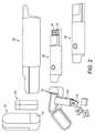
図1は、本発明の第1の態様の一例による、ディスペンサ10を使用する気化器20のロードを概略的に示す。この例では、気化器20は、ディスペンサ10からの未使用の消耗品12をロードされている。 FIG. 1 schematically shows the loading of a
ディスペンサ10は、未使用の消耗品12を貯蔵するための第1の貯蔵部11及び第1の貯蔵部11への開口部を閉じるための第1の蓋13を含む一方、気化器20は、加熱チャンバ22及び加熱チャンバ22への開口部を閉じるための第2の蓋21を含む。 The
第1の蓋13は、第1の蓋13に外力が加えられていないとき(例えば、状態A及びD)、第1の貯蔵部11への開口部が閉じられるように、第1の圧縮ばね14と機械的に連通するように配置されている。 The
第2の蓋21は、第2の蓋21に外力が加えられていないとき(例えば、状態A及びD)、加熱チャンバ22への開口部が閉じられるように、第2の圧縮ばね23と機械的に連通するように配置されている。 The
状態Aでは、ディスペンサ10及び気化器20は、第1/第5の相対位置にある。 In state A, the
状態Aから状態Bに移行すると、気化器20をディスペンサ10と係合させることにより、第1の蓋13及び第2の蓋21がそれらのそれぞれの閉位置から移動できることが分かり得る。 When transitioning from the state A to the state B, it can be seen that the
状態Bから状態Cに移行すると、未使用の消耗品12が重力で第1の貯蔵部11から加熱チャンバ22に移送され得るように、第1の貯蔵部11の開口部は、加熱チャンバ22の開口部と整列することが分かり得る。状態Cでは、ディスペンサ10及び気化器20は、第2/第6の相対位置にある。 The opening of the
状態Cから状態Dに移行すると、気化器20をディスペンサ10から切り離すことにより、第1の蓋13及び第2の蓋21がそれらのそれぞれの閉位置に戻ることができることが分かり得る。状態Dでは、ディスペンサ10及び気化器20は、第1の相対位置に戻り、未使用の消耗品12は、第1の貯蔵部11から加熱チャンバ22に移送される。 After transitioning from state C to state D, it can be seen that by disconnecting the
図2は、図1で使用する気化器及びディスペンサのコンピュータ生成レンダリングを示す。図1で述べた特徴に加えて、取り外された交換のための第1の貯蔵部11bを貯蔵するためのカートリッジ11aも示されている。例えば、未使用の消耗品12で満たされた、取り外された交換のための第1の貯蔵部11bを含むカートリッジ11aは、ユーザが望むときに第1の貯蔵部11がディスペンサ10から取り外され、取り外された交換のための第1の貯蔵部11bと交換されるように、図1のディスペンサ10と共に使用され得る。 FIG. 2 shows a computer-generated rendering of the vaporizer and dispenser used in FIG. In addition to the features described in FIG. 1, a
図3は、本発明の第1の態様の第1の実施形態の好ましいアセンブリの一例による、ディスペンサ30を使用する気化器40のアンロード及びリロードを概略的に示す。この例では、気化器40は、使用済みの消耗品42をディスペンサ30内にアンロードし、同じディスペンサ30から未使用の消耗品35をリロードする。 FIG. 3 schematically illustrates unloading and reloading of a vaporizer 40 using a
ディスペンサ30は、未使用の消耗品35を貯蔵するための第1の貯蔵部36、第1の貯蔵部36への開口部を閉じるための第1の蓋37、使用済みの消耗品42を貯蔵するための第2の貯蔵部33、第2の貯蔵部33への開口部を閉じるための第2の蓋32及び第1の貯蔵部36を第2の貯蔵部33から分離する可動の仕切り34を含む一方、気化器40は、加熱チャンバ43及び加熱チャンバ43への開口部を閉じるための第3の蓋41を含む。 The
第1の蓋37は、第1の蓋37に外力が加えられていないとき(例えば、状態A~D及びG)、第1の貯蔵部36への開口部が閉じられるように、第1の圧縮ばね38と機械的に連通するように配置されている。 The
第2の蓋32は、第2の蓋32に外力が加えられていないとき(例えば、状態A及びD~G)、第2の貯蔵部33への開口部が閉じられるように、第2の圧縮ばね31と機械的に連通するように配置されている。 The
第3の蓋41は、第3の蓋41に外力が加えられていないとき(例えば、状態A、D及びG)、加熱チャンバ43への開口部が閉じられるように、第3の圧縮ばね44と機械的に連通するように配置されている。 The third lid 41 has a
状態Aでは、ディスペンサ30及び気化器40は、第1/第3/第5の相対位置にある。 In state A, the
状態Aから状態Bに移行すると、気化器40をディスペンサ30と係合させることにより、第2の蓋32及び第3の蓋41がそれらのそれぞれの閉位置から移動できることが分かり得る。 When transitioning from the state A to the state B, it can be seen that by engaging the vaporizer 40 with the
状態Bから状態Cに移行すると、使用済みの消耗品42が重力で加熱チャンバ43から第2の貯蔵部33に移送され得るように、加熱チャンバ43の開口部は、第2の貯蔵部33の開口部と整列することが分かり得る。状態Cでは、ディスペンサ30及び気化器40は、第4/第6の相対位置にある。 The opening of the
状態Cから状態Dに移行すると、気化器40をディスペンサ30から切り離すことにより、第2の蓋32及び第3の蓋41がそれらのそれぞれの閉位置に戻ることができることが分かり得る。状態Dでは、ディスペンサ30及び気化器40は、第1/第3/第5の相対位置に戻り、使用済みの消耗品42は、加熱チャンバ43から第2の貯蔵部33に移送される。 After transitioning from state C to state D, it can be seen that by disconnecting the vaporizer 40 from the
状態Dから状態Eに移行すると、気化器40をディスペンサ30と係合させることにより、第1の蓋37及び第3の蓋41がそれらのそれぞれの閉位置から移動できることが分かり得る。 When transitioning from the state D to the state E, it can be seen that by engaging the vaporizer 40 with the
状態Eから状態Fに移行すると、未使用の消耗品35が重力で第1の貯蔵部36から加熱チャンバ43に移送され得るように、第1の貯蔵部36の開口部は、加熱チャンバ43の開口部と整列することが分かり得る。状態Fでは、ディスペンサ30及び気化器40は、第2/第6の相対位置にある。 The opening of the
状態Fから状態Gに移行すると、気化器40をディスペンサ30から切り離すことにより、第1の蓋37及び第3の蓋41がそれらのそれぞれの閉位置に戻ることができることが分かり得る。状態Dでは、ディスペンサ30及び気化器40は、第1/第3/第5の相対位置に戻り、未使用の消耗品35は、第1の貯蔵部35から加熱チャンバ43に移送される。 It can be seen that when transitioning from state F to state G, the
図4は、本発明の第1の態様の第1の実施形態の代替的な好ましいアセンブリの一例による、ディスペンサ50を使用する気化器60のアンロードを概略的に示す。この例では、気化器60は、使用済みの消耗品62をディスペンサ50内にアンロードしている。未使用の消耗品52を気化器60にロードするための機構は、図1の状態A~Dに示されている方法で機能する。 FIG. 4 schematically shows the unloading of a vaporizer 60 using a
ディスペンサ50は、未使用の消耗品52を貯蔵するための第1の貯蔵部51、第1の貯蔵部51への開口部を閉じるための第1の蓋53、使用済みの消耗品62を貯蔵するための第2の貯蔵部56及び第2の貯蔵部56への開口部を閉じるための第2の蓋55を含む一方、気化器60は、加熱チャンバ63及び加熱チャンバ63への開口部を閉じるための第3の蓋61を含む。 The
第1の蓋53及び第2の蓋55は、互いに固定され、第1の蓋53及び第2の蓋55に外力が加えられていないとき(例えば、状態A)、第1の貯蔵部51及び第2の貯蔵部56への開口部が閉じられるように、第1の圧縮ばね54と機械的に連通するように配置されている。 The
第3の蓋61は、第3の蓋61に外力が加えられていないとき(例えば、状態A)、加熱チャンバ63への開口部が閉じられるように、第2の圧縮ばね64と機械的に連通するように配置されている。 The
状態Aでは、ディスペンサ50及び気化器60は、第1/第3/第5の相対位置にある。 In state A, the
状態Aから状態Bに移行すると、気化器60をディスペンサ50と係合させることにより、第1の蓋53、第2の蓋55及び第3の蓋41がそれらのそれぞれの閉位置から移動できることが分かり得る。 When transitioning from the state A to the state B, the
状態Bから状態Cに移行すると、気化器60の向きにより、使用済みの消耗品62が重力で加熱チャンバ63から第2の貯蔵部56に移送され得るように、加熱チャンバ63の開口部は、第2の貯蔵部56の開口部と整列することが分かり得る。状態Cでは、ディスペンサ50及び気化器60は、第4/第6の相対位置にある。気化器60をディスペンサ50から切り離すことにより、図2の状態C~Dに示される方法で機能する。 When transitioning from state B to state C, the opening of the
図5は、本発明の第1の態様の第2の実施形態の好ましいアセンブリの一例による、ディスペンサ70を使用する気化器80のアンロードを概略的に示す。この例では、気化器80は、使用済みの消耗品82をディスペンサ70内にアンロードしている。未使用の消耗品72を気化器80にロードするための機構は、図1の状態A~Dに示されている方法で機能する。 FIG. 5 schematically shows the unloading of a
ディスペンサ70は、未使用の消耗品72を貯蔵するための第1の貯蔵部71、第1の貯蔵部71への開口部を閉じるための第1の蓋73、ディスペンサ開口部76及びディスペンサ開口部76を閉じるための第2の蓋75を含む一方、気化器80は、加熱チャンバ83及び加熱チャンバ83への開口部を閉じるための第3の蓋81を含む。 The
第1の蓋73及び第2の蓋75は、互いに固定され、第1の蓋73及び第2の蓋75に外力が加えられていないとき(例えば、状態A)、第1の貯蔵部71への開口部及びディスペンサ開口部76が閉じられるように、第1の圧縮ばね74と機械的に連通するように配置されている。 The
第3の蓋81は、第3の蓋81に外力が加えられていないとき(例えば、状態A)、加熱チャンバ83への開口部が閉じられるように、第2の圧縮ばね84と機械的に連通するように配置されている。 The
状態Aでは、ディスペンサ70及び気化器80は、第1/第3/第5の相対位置にある。 In state A, the
状態Aから状態Bに移行すると、気化器80をディスペンサ70と係合させることにより、第1の蓋73、第2の蓋75及び第3の蓋81がそれらのそれぞれの閉位置から移動できることが分かり得る。 When transitioning from the state A to the state B, the
状態Bから状態Cに移行すると、気化器80の向きにより、使用済みの消耗品82が重力で加熱チャンバ83から(例えば、ゴミ箱に)排出され得るように、加熱チャンバ83の開口部は、ディスペンサ開口部76と整列することが分かり得る。状態Cでは、ディスペンサ70及び気化器80は、第4/第6の相対位置にある。気化器80をディスペンサ70から切り離すことにより、図2の状態C~Dに示される方法で機能する。 When transitioning from state B to state C, the opening of the
上述のディスペンサ及び/又は気化器は、任意選択的に、システムの現在の状態を検出するための1つ以上のセンサ及び1つ以上のセンサからの入力を解釈するための制御回路も含み得る。そのようなセンサの一例は、図1の修正形態として図6に示されている。 The dispenser and / or vaporizer described above may optionally include one or more sensors for detecting the current state of the system and a control circuit for interpreting inputs from the one or more sensors. An example of such a sensor is shown in FIG. 6 as a modified form of FIG.
例えば、システムは、図6の状態Cを検出するための第1のセンサ24を含み得、ここで、第1の貯蔵部11の開口部は、加熱チャンバ22の開口部と整列される。換言すれば、第1のセンサ24は、気化器20のディスペンサ10との係合を検出するように構成されている。 For example, the system may include a
追加的又は代替的に、気化器20は、加熱チャンバ22への開口部が状態Dのように閉じられるときを検出するための第2のセンサ26を含み得る。第2のセンサからの信号のエッジイベントは、第2の蓋21の閉鎖を検出するために制御回路によって使用され得る。 Additional or alternative, the
気化器20が、状態C及びDの両方のためのセンサ及び状態Cとそれに続く状態Dのシーケンスを検出するように構成された制御回路を備えている場合、気化器は、加熱チャンバ22がロードされたときを検出することができる。これは、例えば、気化器20の起動を制御して、加熱チャンバ22内の消耗品12を加熱するために使用され得る。センサ及び制御回路は、例えば、分配イベントをカウントし、ディスペンサに残っている未使用の消耗品12の数を追跡するために、ディスペンサで等しく使用することができる。 If the
センサのそれぞれは、気化器20及び/又はディスペンサ10の構成要素の特定の相対的位置決めが達成されるときを検出するための近接センサである。例えば、センサのそれぞれは、第1の構成要素に取り付けられ得、第2の構成要素に取り付けられた検出可能な要素を検出するように構成され得る。センサは、例えば、従来のセンサ又は更にスイッチ機構であり得る。しかしながら、システムは、好ましくは、磁石(検出可能要素)とホール効果センサとの1つ以上の対及び/又は反射面(検出可能要素)と光学センサとの対を含む。 Each of the sensors is a proximity sensor for detecting when a particular relative positioning of the components of the
例えば、状態Cを検出するためのセンサは、ディスペンサ10に第1の磁石15を設け、気化器20に第1のホール効果センサ24を設けることによって実装することができる。状態Cに示されるように、ディスペンサ及び気化器が状態Cにあるとき、第1の磁石15は、第1のホール効果センサ24の近くにあり、第1のホール効果センサ24によって検出され得る。 For example, the sensor for detecting the state C can be mounted by providing the
別の例として、状態Dを検出するためのセンサは、気化器20に第2の磁石25及び第2のホール効果センサ26を設けることによって実装され得、第2の磁石25は、第2の蓋21及び加熱チャンバ22の一方に取り付けられ、第2のホール効果センサ26は、第2の蓋21及び加熱チャンバ22の他方に取り付けられる。図1に示されるように、磁石25及び第2のホール効果センサ26は、状態Dのように加熱チャンバ22への開口部が閉じられているときにそれらが互いに接近し、状態Cのように加熱チャンバ22への開口部が開いているときにそれらが更に離れるように配置され得る。したがって、第2の磁石25の磁場がより強くなるときを検出することにより、第2のホール効果センサ26は、加熱チャンバ22への開口部が閉じていることを検出することができる。 As another example, the sensor for detecting the state D can be mounted by providing the
有利には、状態Cで第1及び第2の磁石15、25を互いに接近するように配置することにより、ホール効果センサを使用して、第1及び第2のホール効果センサ24、26を必要とすることなく状態C及びDの両方を検出し、第1及び第2の磁石15、25のいずれが近くにあるかを区別することができる。一実施形態では、第1の磁石を省略し得、ホール効果センサ24、26は、それぞれ第2の蓋21の異なる位置で第2の磁石25を検出することができる。別の実施形態では、第1の磁石15は、第2の磁石25よりも強力であり得、且つ第1のホール効果センサ24は、第2のホール効果センサ26よりも低感度であるように構成され得、それにより、第1のホール効果センサ24は、(気化器20がディスペンサ10と係合していることを示す)第1の磁石15を(加熱チャンバ22への開口部が開いていることのみを示す)第2の磁石25から区別することができる。 Advantageously, the Hall effect sensor is used to require the first and second
Claims (21)
Translated fromJapanese第1の貯蔵部であって、その中に少なくとも1つの固体又は半固体の気化可能な消耗品を貯蔵するためのものであり、開口部であって、それを通して固体又は半固体の気化可能な消耗品を分配するための開口部を含む第1の貯蔵部と、
第1の蓋であって、閉位置にあるときにそれが前記第1の貯蔵部の前記開口部を閉じるように配置される第1の蓋と
を含み、使用時、気化器を前記ディスペンサと係合させることが、前記第1の貯蔵部の前記開口部を加熱チャンバの開口部と整列させることにより、前記第1の貯蔵部内に貯蔵された固体又は半固体の気化可能な消耗品を前記気化器の前記加熱チャンバにロードするように配置される、ディスペンサ。A dispenser for distributing solid or semi-solid vaporizable consumables to a vaporizer.
A first reservoir for storing at least one solid or semi-solid vaporizable consumable in it, an opening through which the solid or semi-solid can be vaporized. A first storage unit containing an opening for distributing consumables,
A first lid, including a first lid that is arranged to close the opening of the first reservoir when in the closed position, the vaporizer with the dispenser in use. Engagement allows the solid or semi-solid vaporizable consumables stored in the first reservoir by aligning the opening of the first reservoir with the opening of the heating chamber. A dispenser arranged to load into the heating chamber of the vaporizer.
加熱チャンバであって、それから蒸気を生成するために固体又は半固体の気化可能な消耗品を受容及び加熱するためのものであり、開口部であって、それを通して固体又は半固体の気化可能な消耗品を受容及び排出するための開口部を含む加熱チャンバと、
第3の蓋であって、閉位置にあるときにそれが前記加熱チャンバの前記開口部を閉じるように配置される第3の蓋と
を含み、使用時、前記気化器を前記ディスペンサと係合させることが、前記第1の貯蔵部の前記開口部を前記加熱チャンバの前記開口部と整列させて、前記消耗品を受容することにより、前記第1の貯蔵部内に貯蔵された固体又は半固体の気化可能な消耗品を前記加熱チャンバにロードするように配置される、気化器。A vaporizer for use in combination with the dispenser according to any one of claims 1 to 10.
A heating chamber for receiving and heating solid or semi-solid vaporizable consumables to generate steam from it, and an opening through which the solid or semi-solid can be vaporized. A heating chamber containing openings for receiving and discharging consumables,
A third lid comprising a third lid that is arranged to close the opening of the heating chamber when in the closed position, engaging the vaporizer with the dispenser in use. By aligning the opening of the first storage with the opening of the heating chamber and receiving the consumables, the solid or semi-solid stored in the first storage. A vaporizer arranged to load the vaporizable consumables into the heating chamber.
前記第2の蓋及び前記第3の蓋をそれらのそれぞれの開位置に付勢し、且つ前記加熱チャンバの前記開口部を前記第2の貯蔵部の前記開口部と整列させ、それにより、前記加熱チャンバ内に貯蔵された固体又は半固体の気化可能な消耗品が前記加熱チャンバから前記第2の貯蔵部に受容されることを可能にするか、又は
前記第1及び/又は第2の蓋並びに前記第3の蓋をそれらのそれぞれの開位置に付勢し、且つ前記加熱チャンバの前記開口部を前記ディスペンサの前記開口部と整列させ、それにより、前記加熱チャンバ内に貯蔵された固体又は半固体の気化可能な消耗品が前記システムから排出されることを可能にするかのいずれかであるように配置される、請求項18に記載の供給システム。The vaporizer and the dispenser may, in use, engage the vaporizer with the dispenser in order to unload the heating chamber.
The second lid and the third lid are urged to their respective open positions and the opening of the heating chamber is aligned with the opening of the second storage, thereby said. Allows solid or semi-solid vaporizable consumables stored in the heating chamber to be received from the heating chamber into the second reservoir, or the first and / or second lid. And the third lid is urged to their respective open positions and the opening of the heating chamber is aligned with the opening of the dispenser, thereby solid or solid stored in the heating chamber. 18. The supply system of claim 18, wherein the semi-solid vaporizable consumables are arranged so as to allow them to be ejected from the system.
Applications Claiming Priority (3)
| Application Number | Priority Date | Filing Date | Title |
|---|---|---|---|
| EP18202523 | 2018-10-25 | ||
| EP18202523.9 | 2018-10-25 | ||
| PCT/EP2019/078612WO2020083852A1 (en) | 2018-10-25 | 2019-10-21 | Dispenser and complementary vaporizer |
Publications (1)
| Publication Number | Publication Date |
|---|---|
| JP2022505286Atrue JP2022505286A (en) | 2022-01-14 |
Family
ID=63998558
Family Applications (1)
| Application Number | Title | Priority Date | Filing Date |
|---|---|---|---|
| JP2021521255AWithdrawnJP2022505286A (en) | 2018-10-25 | 2019-10-21 | Dispenser and complementary vaporizer |
Country Status (7)
| Country | Link |
|---|---|
| US (1) | US20210392952A1 (en) |
| EP (1) | EP3869984A1 (en) |
| JP (1) | JP2022505286A (en) |
| KR (1) | KR20210080360A (en) |
| CN (1) | CN112804898A (en) |
| EA (1) | EA202190764A1 (en) |
| WO (1) | WO2020083852A1 (en) |
Families Citing this family (2)
| Publication number | Priority date | Publication date | Assignee | Title |
|---|---|---|---|---|
| WO2025108935A1 (en)* | 2023-11-20 | 2025-05-30 | Jt International Sa | Consumable holding and feeding unit for an aerosol-generating device |
| US12288439B1 (en) | 2024-04-17 | 2025-04-29 | SkyX IP Holdings | LLC | Apparatus and method for an oral nicotine dispensing system |
Family Cites Families (37)
| Publication number | Priority date | Publication date | Assignee | Title |
|---|---|---|---|---|
| US4223801A (en)* | 1978-01-26 | 1980-09-23 | Carlson Torsten S | Automatic periodic drug dispensing system |
| US5335816A (en)* | 1989-09-29 | 1994-08-09 | Healthtech Services Corporation | Interactive medication delivery system for medication prepackaged in blister packs |
| AU5083096A (en)* | 1995-10-27 | 1997-05-01 | Arthur G. Fuller Jr. | Package container with waste disposal compartment |
| DE19817417A1 (en)* | 1998-04-18 | 1999-10-21 | Pfeiffer Erich Gmbh & Co Kg | Dispenser for media, especially powder |
| DE19854012C2 (en)* | 1998-11-12 | 2001-05-10 | Reemtsma H F & Ph | Inhalable aerosol delivery system |
| DE19919724C2 (en)* | 1999-04-30 | 2002-05-16 | Peter Gutmann | Transportable container for holding the remains of tobacco products, in particular cigarettes or cigars |
| CA2313069C (en)* | 1999-07-01 | 2006-05-09 | Filtertek Inc. | Semisolid product dispensing head |
| US6651809B2 (en)* | 2001-08-13 | 2003-11-25 | Christopher A. Holler | Apparatus and method for cigar storage |
| GB0702894D0 (en)* | 2007-02-14 | 2007-03-28 | British American Tobacco Co | Container for smoking articles |
| WO2008131549A1 (en)* | 2007-04-25 | 2008-11-06 | Grafton Canada Limited | Motor rotating carousel assembly and method for securely dispensing items |
| US20080276948A1 (en)* | 2007-05-09 | 2008-11-13 | Philip Morris Usa Inc. | Chewing article for oral tobacco delivery |
| US8714405B2 (en)* | 2007-08-10 | 2014-05-06 | Parata Systems, Llc | Device for staging and dispensing tablets useful in system and method for dispensing prescriptions |
| GB201109174D0 (en)* | 2011-06-01 | 2011-07-13 | British American Tobacco Co | Smoking article |
| US20130255702A1 (en)* | 2012-03-28 | 2013-10-03 | R.J. Reynolds Tobacco Company | Smoking article incorporating a conductive substrate |
| CN103202539B (en)* | 2013-04-24 | 2015-10-28 | 上海烟草集团有限责任公司 | Cigarette heater and cigarette used thereof |
| EP2837582A1 (en)* | 2013-08-14 | 2015-02-18 | Philip Morris Products S.A. | System and method for transferring material |
| GB201413027D0 (en)* | 2014-02-28 | 2014-09-03 | Beyond Twenty Ltd | Beyond 4 |
| CA2886358A1 (en)* | 2014-03-28 | 2015-09-28 | C.H. & I. Technologies, Inc. | Aerosol refill cartridge |
| US10435201B2 (en)* | 2014-04-29 | 2019-10-08 | Jt International S.A. | Packaging assembly |
| DE102014117985A1 (en)* | 2014-05-28 | 2015-12-03 | Gaudlitz Gmbh | Device for separating shaped bodies consisting of or containing one or more pharmaceutical active ingredients, in particular capsules and tablets |
| WO2016079151A1 (en)* | 2014-11-17 | 2016-05-26 | Mcneil Ab | Child-resistant container for nicotine-containing cartridges |
| US9474304B2 (en)* | 2014-12-30 | 2016-10-25 | Model Row Investments, LLC | Single dose smoking device |
| EP3297711A4 (en)* | 2015-05-22 | 2019-01-16 | Compressed Perforated Puck Technologies Inc. | SPRAY APPARATUS FOR COMPRESSED TABLET AND BULK PLANT SOURCE MATERIALS |
| WO2017020275A1 (en)* | 2015-08-05 | 2017-02-09 | 惠州市吉瑞科技有限公司深圳分公司 | Electronic cigarette |
| US9932166B2 (en)* | 2015-08-11 | 2018-04-03 | Salt Mag LLC | Tablet dispenser for athletes |
| CA2997119C (en)* | 2015-09-01 | 2023-10-24 | Beyond Twenty Limited | Electronic vaporiser system |
| US9498002B1 (en)* | 2015-09-18 | 2016-11-22 | Revolver Pen, Llc | Multi-chamber vaporizer |
| EP3383207B1 (en)* | 2015-12-03 | 2021-02-03 | JT International S.A. | Reservoir assembly for a personal vaporizer device |
| DE102016106283A1 (en)* | 2016-04-06 | 2017-10-12 | Xeo Holding GmbH | smoking device |
| EP3462939B1 (en)* | 2016-05-25 | 2021-05-19 | Philip Morris Products S.A. | Aerosol-generating article comprising a piston and aerosol-generating device |
| KR102523292B1 (en)* | 2016-07-14 | 2023-04-20 | 필립모리스 프로덕츠 에스.에이. | Fluid Permeable Heater Assemblies and Cartomizer Cartridges for Aerosol Generating Systems |
| KR20190028718A (en)* | 2016-07-29 | 2019-03-19 | 필립모리스 프로덕츠 에스.에이. | An aerosol generating system comprising a gel-containing cartridge and an apparatus for heating a cartridge |
| EP3512369B1 (en)* | 2016-09-14 | 2024-03-27 | Altria Client Services LLC | Smoking device |
| US11576424B2 (en)* | 2017-04-05 | 2023-02-14 | Altria Client Services Llc | Susceptor for use with an inductively heated aerosol-generating device or system |
| KR102231228B1 (en)* | 2017-05-26 | 2021-03-24 | 주식회사 케이티앤지 | Apparatus and method for generating aerosol having cigarette insertion detection function |
| CN207476956U (en)* | 2017-09-30 | 2018-06-12 | 深圳市合元科技有限公司 | It can oiling atomizer and electronic cigarette |
| CN107692327B (en)* | 2017-11-10 | 2020-03-27 | 绿烟实业(深圳)有限公司 | Heating non-combustion smoking set and charging base |
- 2019
- 2019-10-21JPJP2021521255Apatent/JP2022505286A/ennot_activeWithdrawn
- 2019-10-21EAEA202190764Apatent/EA202190764A1/enunknown
- 2019-10-21KRKR1020217009421Apatent/KR20210080360A/ennot_activeAbandoned
- 2019-10-21WOPCT/EP2019/078612patent/WO2020083852A1/ennot_activeCeased
- 2019-10-21USUS17/282,913patent/US20210392952A1/ennot_activeAbandoned
- 2019-10-21EPEP19786995.1Apatent/EP3869984A1/ennot_activeWithdrawn
- 2019-10-21CNCN201980066706.9Apatent/CN112804898A/enactivePending
Also Published As
| Publication number | Publication date |
|---|---|
| WO2020083852A1 (en) | 2020-04-30 |
| EA202190764A1 (en) | 2021-07-22 |
| EP3869984A1 (en) | 2021-09-01 |
| US20210392952A1 (en) | 2021-12-23 |
| CN112804898A (en) | 2021-05-14 |
| KR20210080360A (en) | 2021-06-30 |
Similar Documents
| Publication | Publication Date | Title |
|---|---|---|
| JP7291978B2 (en) | nicotine delivery system | |
| JP5768192B2 (en) | Power supply system for portable aerosol generator | |
| CN106455706B (en) | Inhaler | |
| JP2022505286A (en) | Dispenser and complementary vaporizer | |
| JP2022522669A (en) | Articles for use with aerosol generation systems and aerosol generation systems | |
| KR102820240B1 (en) | Case for aerosol generating device with detector | |
| JP2022502014A (en) | Steam generator | |
| WO2017108392A1 (en) | Packaging for at least one electronic smoking device product | |
| JP7553452B2 (en) | Case for an aerosol generating device with a holder for a power supply | |
| KR102492588B1 (en) | smoking device | |
| US20240130441A1 (en) | Charger and aerosol-generating system with improved closing means | |
| JP7465262B2 (en) | Aerosol Generation System | |
| KR20230041757A (en) | Case for aerosol generating device | |
| KR20220083756A (en) | Chargers and aerosol-generating systems with multi-component covers | |
| US20230354910A1 (en) | Aerosol provision system | |
| KR20230129237A (en) | Aerosol-generating set comprising a pair of magnetic elements, and associated method of operation | |
| CN118575995A (en) | Evaporator | |
| KR20230160273A (en) | Aerosol-generating devices and methods of controlling such aerosol-generating devices | |
| JP2025520342A (en) | CHARGING UNIT CONFIGURED TO OPERATE WITH AN AEROSOL GENERATING DEVICE, AND ASSOCIATED AEROSOL GENERATING ASSEMBLY AND METHOD OF OPERATION - Patent application | |
| RU2806271C2 (en) | Aerosol generation system and aerosol generation method | |
| RU2816153C1 (en) | Charging device and aerosol generation system with improved closure means | |
| US20250256872A1 (en) | Apparatus for capactitive liquid sensing of refillable articles for aerosol provision systems | |
| RU2816489C1 (en) | Charging device and aerosol generating system with multicomponent cover | |
| WO2024184652A1 (en) | Refilling unit and refill reservoir | |
| CN118076249A (en) | Refill device |
Legal Events
| Date | Code | Title | Description |
|---|---|---|---|
| A621 | Written request for application examination | Free format text:JAPANESE INTERMEDIATE CODE: A621 Effective date:20220728 | |
| A761 | Written withdrawal of application | Free format text:JAPANESE INTERMEDIATE CODE: A761 Effective date:20230707 |