JP2022505003A - Laminated fluid circuit for fluid cartridges - Google Patents
Laminated fluid circuit for fluid cartridgesDownload PDFInfo
- Publication number
- JP2022505003A JP2022505003AJP2020572661AJP2020572661AJP2022505003AJP 2022505003 AJP2022505003 AJP 2022505003AJP 2020572661 AJP2020572661 AJP 2020572661AJP 2020572661 AJP2020572661 AJP 2020572661AJP 2022505003 AJP2022505003 AJP 2022505003A
- Authority
- JP
- Japan
- Prior art keywords
- substrate
- layer
- fluid
- flexible conduit
- channel
- Prior art date
- Legal status (The legal status is an assumption and is not a legal conclusion. Google has not performed a legal analysis and makes no representation as to the accuracy of the status listed.)
- Granted
Links
Images


Classifications
- B—PERFORMING OPERATIONS; TRANSPORTING
- B01—PHYSICAL OR CHEMICAL PROCESSES OR APPARATUS IN GENERAL
- B01L—CHEMICAL OR PHYSICAL LABORATORY APPARATUS FOR GENERAL USE
- B01L3/00—Containers or dishes for laboratory use, e.g. laboratory glassware; Droppers
- B01L3/50—Containers for the purpose of retaining a material to be analysed, e.g. test tubes
- B01L3/502—Containers for the purpose of retaining a material to be analysed, e.g. test tubes with fluid transport, e.g. in multi-compartment structures
- B01L3/5027—Containers for the purpose of retaining a material to be analysed, e.g. test tubes with fluid transport, e.g. in multi-compartment structures by integrated microfluidic structures, i.e. dimensions of channels and chambers are such that surface tension forces are important, e.g. lab-on-a-chip
- B01L3/502707—Containers for the purpose of retaining a material to be analysed, e.g. test tubes with fluid transport, e.g. in multi-compartment structures by integrated microfluidic structures, i.e. dimensions of channels and chambers are such that surface tension forces are important, e.g. lab-on-a-chip characterised by the manufacture of the container or its components
- B—PERFORMING OPERATIONS; TRANSPORTING
- B01—PHYSICAL OR CHEMICAL PROCESSES OR APPARATUS IN GENERAL
- B01L—CHEMICAL OR PHYSICAL LABORATORY APPARATUS FOR GENERAL USE
- B01L3/00—Containers or dishes for laboratory use, e.g. laboratory glassware; Droppers
- B01L3/50—Containers for the purpose of retaining a material to be analysed, e.g. test tubes
- B01L3/502—Containers for the purpose of retaining a material to be analysed, e.g. test tubes with fluid transport, e.g. in multi-compartment structures
- B01L3/5027—Containers for the purpose of retaining a material to be analysed, e.g. test tubes with fluid transport, e.g. in multi-compartment structures by integrated microfluidic structures, i.e. dimensions of channels and chambers are such that surface tension forces are important, e.g. lab-on-a-chip
- B01L3/502715—Containers for the purpose of retaining a material to be analysed, e.g. test tubes with fluid transport, e.g. in multi-compartment structures by integrated microfluidic structures, i.e. dimensions of channels and chambers are such that surface tension forces are important, e.g. lab-on-a-chip characterised by interfacing components, e.g. fluidic, electrical, optical or mechanical interfaces
- B—PERFORMING OPERATIONS; TRANSPORTING
- B01—PHYSICAL OR CHEMICAL PROCESSES OR APPARATUS IN GENERAL
- B01L—CHEMICAL OR PHYSICAL LABORATORY APPARATUS FOR GENERAL USE
- B01L3/00—Containers or dishes for laboratory use, e.g. laboratory glassware; Droppers
- B—PERFORMING OPERATIONS; TRANSPORTING
- B01—PHYSICAL OR CHEMICAL PROCESSES OR APPARATUS IN GENERAL
- B01L—CHEMICAL OR PHYSICAL LABORATORY APPARATUS FOR GENERAL USE
- B01L3/00—Containers or dishes for laboratory use, e.g. laboratory glassware; Droppers
- B01L3/50—Containers for the purpose of retaining a material to be analysed, e.g. test tubes
- B01L3/502—Containers for the purpose of retaining a material to be analysed, e.g. test tubes with fluid transport, e.g. in multi-compartment structures
- B01L3/5027—Containers for the purpose of retaining a material to be analysed, e.g. test tubes with fluid transport, e.g. in multi-compartment structures by integrated microfluidic structures, i.e. dimensions of channels and chambers are such that surface tension forces are important, e.g. lab-on-a-chip
- B01L3/502738—Containers for the purpose of retaining a material to be analysed, e.g. test tubes with fluid transport, e.g. in multi-compartment structures by integrated microfluidic structures, i.e. dimensions of channels and chambers are such that surface tension forces are important, e.g. lab-on-a-chip characterised by integrated valves
- B—PERFORMING OPERATIONS; TRANSPORTING
- B01—PHYSICAL OR CHEMICAL PROCESSES OR APPARATUS IN GENERAL
- B01L—CHEMICAL OR PHYSICAL LABORATORY APPARATUS FOR GENERAL USE
- B01L3/00—Containers or dishes for laboratory use, e.g. laboratory glassware; Droppers
- B01L3/52—Containers specially adapted for storing or dispensing a reagent
- B01L3/527—Containers specially adapted for storing or dispensing a reagent for a plurality of reagents
- B—PERFORMING OPERATIONS; TRANSPORTING
- B29—WORKING OF PLASTICS; WORKING OF SUBSTANCES IN A PLASTIC STATE IN GENERAL
- B29C—SHAPING OR JOINING OF PLASTICS; SHAPING OF MATERIAL IN A PLASTIC STATE, NOT OTHERWISE PROVIDED FOR; AFTER-TREATMENT OF THE SHAPED PRODUCTS, e.g. REPAIRING
- B29C53/00—Shaping by bending, folding, twisting, straightening or flattening; Apparatus therefor
- B29C53/02—Bending or folding
- B29C53/04—Bending or folding of plates or sheets
- B29C53/06—Forming folding lines by pressing or scoring
- G—PHYSICS
- G01—MEASURING; TESTING
- G01N—INVESTIGATING OR ANALYSING MATERIALS BY DETERMINING THEIR CHEMICAL OR PHYSICAL PROPERTIES
- G01N35/00—Automatic analysis not limited to methods or materials provided for in any single one of groups G01N1/00 - G01N33/00; Handling materials therefor
- G01N35/10—Devices for transferring samples or any liquids to, in, or from, the analysis apparatus, e.g. suction devices, injection devices
- G01N35/1002—Reagent dispensers
- B—PERFORMING OPERATIONS; TRANSPORTING
- B01—PHYSICAL OR CHEMICAL PROCESSES OR APPARATUS IN GENERAL
- B01L—CHEMICAL OR PHYSICAL LABORATORY APPARATUS FOR GENERAL USE
- B01L2200/00—Solutions for specific problems relating to chemical or physical laboratory apparatus
- B01L2200/12—Specific details about manufacturing devices
- B—PERFORMING OPERATIONS; TRANSPORTING
- B01—PHYSICAL OR CHEMICAL PROCESSES OR APPARATUS IN GENERAL
- B01L—CHEMICAL OR PHYSICAL LABORATORY APPARATUS FOR GENERAL USE
- B01L2200/00—Solutions for specific problems relating to chemical or physical laboratory apparatus
- B01L2200/16—Reagents, handling or storing thereof
- B—PERFORMING OPERATIONS; TRANSPORTING
- B01—PHYSICAL OR CHEMICAL PROCESSES OR APPARATUS IN GENERAL
- B01L—CHEMICAL OR PHYSICAL LABORATORY APPARATUS FOR GENERAL USE
- B01L2300/00—Additional constructional details
- B01L2300/04—Closures and closing means
- B01L2300/041—Connecting closures to device or container
- B01L2300/044—Connecting closures to device or container pierceable, e.g. films, membranes
- B—PERFORMING OPERATIONS; TRANSPORTING
- B01—PHYSICAL OR CHEMICAL PROCESSES OR APPARATUS IN GENERAL
- B01L—CHEMICAL OR PHYSICAL LABORATORY APPARATUS FOR GENERAL USE
- B01L2300/00—Additional constructional details
- B01L2300/04—Closures and closing means
- B01L2300/046—Function or devices integrated in the closure
- B01L2300/047—Additional chamber, reservoir
- B—PERFORMING OPERATIONS; TRANSPORTING
- B01—PHYSICAL OR CHEMICAL PROCESSES OR APPARATUS IN GENERAL
- B01L—CHEMICAL OR PHYSICAL LABORATORY APPARATUS FOR GENERAL USE
- B01L2300/00—Additional constructional details
- B01L2300/06—Auxiliary integrated devices, integrated components
- B01L2300/0627—Sensor or part of a sensor is integrated
- B01L2300/0636—Integrated biosensor, microarrays
- B—PERFORMING OPERATIONS; TRANSPORTING
- B01—PHYSICAL OR CHEMICAL PROCESSES OR APPARATUS IN GENERAL
- B01L—CHEMICAL OR PHYSICAL LABORATORY APPARATUS FOR GENERAL USE
- B01L2300/00—Additional constructional details
- B01L2300/06—Auxiliary integrated devices, integrated components
- B01L2300/0627—Sensor or part of a sensor is integrated
- B01L2300/0645—Electrodes
- B—PERFORMING OPERATIONS; TRANSPORTING
- B01—PHYSICAL OR CHEMICAL PROCESSES OR APPARATUS IN GENERAL
- B01L—CHEMICAL OR PHYSICAL LABORATORY APPARATUS FOR GENERAL USE
- B01L2300/00—Additional constructional details
- B01L2300/06—Auxiliary integrated devices, integrated components
- B01L2300/0672—Integrated piercing tool
- B—PERFORMING OPERATIONS; TRANSPORTING
- B01—PHYSICAL OR CHEMICAL PROCESSES OR APPARATUS IN GENERAL
- B01L—CHEMICAL OR PHYSICAL LABORATORY APPARATUS FOR GENERAL USE
- B01L2300/00—Additional constructional details
- B01L2300/08—Geometry, shape and general structure
- B01L2300/0809—Geometry, shape and general structure rectangular shaped
- B01L2300/0816—Cards, e.g. flat sample carriers usually with flow in two horizontal directions
- B—PERFORMING OPERATIONS; TRANSPORTING
- B01—PHYSICAL OR CHEMICAL PROCESSES OR APPARATUS IN GENERAL
- B01L—CHEMICAL OR PHYSICAL LABORATORY APPARATUS FOR GENERAL USE
- B01L2300/00—Additional constructional details
- B01L2300/08—Geometry, shape and general structure
- B01L2300/0861—Configuration of multiple channels and/or chambers in a single devices
- B01L2300/0877—Flow chambers
- B—PERFORMING OPERATIONS; TRANSPORTING
- B01—PHYSICAL OR CHEMICAL PROCESSES OR APPARATUS IN GENERAL
- B01L—CHEMICAL OR PHYSICAL LABORATORY APPARATUS FOR GENERAL USE
- B01L2300/00—Additional constructional details
- B01L2300/08—Geometry, shape and general structure
- B01L2300/0887—Laminated structure
- B—PERFORMING OPERATIONS; TRANSPORTING
- B01—PHYSICAL OR CHEMICAL PROCESSES OR APPARATUS IN GENERAL
- B01L—CHEMICAL OR PHYSICAL LABORATORY APPARATUS FOR GENERAL USE
- B01L2300/00—Additional constructional details
- B01L2300/12—Specific details about materials
- B—PERFORMING OPERATIONS; TRANSPORTING
- B01—PHYSICAL OR CHEMICAL PROCESSES OR APPARATUS IN GENERAL
- B01L—CHEMICAL OR PHYSICAL LABORATORY APPARATUS FOR GENERAL USE
- B01L2300/00—Additional constructional details
- B01L2300/12—Specific details about materials
- B01L2300/123—Flexible; Elastomeric
- B—PERFORMING OPERATIONS; TRANSPORTING
- B01—PHYSICAL OR CHEMICAL PROCESSES OR APPARATUS IN GENERAL
- B01L—CHEMICAL OR PHYSICAL LABORATORY APPARATUS FOR GENERAL USE
- B01L2300/00—Additional constructional details
- B01L2300/18—Means for temperature control
- B01L2300/1805—Conductive heating, heat from thermostatted solids is conducted to receptacles, e.g. heating plates, blocks
- B01L2300/1827—Conductive heating, heat from thermostatted solids is conducted to receptacles, e.g. heating plates, blocks using resistive heater
- B—PERFORMING OPERATIONS; TRANSPORTING
- B01—PHYSICAL OR CHEMICAL PROCESSES OR APPARATUS IN GENERAL
- B01L—CHEMICAL OR PHYSICAL LABORATORY APPARATUS FOR GENERAL USE
- B01L2400/00—Moving or stopping fluids
- B01L2400/06—Valves, specific forms thereof
- B—PERFORMING OPERATIONS; TRANSPORTING
- B01—PHYSICAL OR CHEMICAL PROCESSES OR APPARATUS IN GENERAL
- B01L—CHEMICAL OR PHYSICAL LABORATORY APPARATUS FOR GENERAL USE
- B01L2400/00—Moving or stopping fluids
- B01L2400/06—Valves, specific forms thereof
- B01L2400/0633—Valves, specific forms thereof with moving parts
- B01L2400/0655—Valves, specific forms thereof with moving parts pinch valves
- B—PERFORMING OPERATIONS; TRANSPORTING
- B01—PHYSICAL OR CHEMICAL PROCESSES OR APPARATUS IN GENERAL
- B01L—CHEMICAL OR PHYSICAL LABORATORY APPARATUS FOR GENERAL USE
- B01L2400/00—Moving or stopping fluids
- B01L2400/06—Valves, specific forms thereof
- B01L2400/0677—Valves, specific forms thereof phase change valves; Meltable, freezing, dissolvable plugs; Destructible barriers
- B01L2400/0683—Valves, specific forms thereof phase change valves; Meltable, freezing, dissolvable plugs; Destructible barriers mechanically breaking a wall or membrane within a channel or chamber
Landscapes
- Chemical & Material Sciences (AREA)
- Health & Medical Sciences (AREA)
- Analytical Chemistry (AREA)
- General Health & Medical Sciences (AREA)
- Chemical Kinetics & Catalysis (AREA)
- Clinical Laboratory Science (AREA)
- Hematology (AREA)
- Dispersion Chemistry (AREA)
- Biochemistry (AREA)
- Pathology (AREA)
- Immunology (AREA)
- General Physics & Mathematics (AREA)
- Physics & Mathematics (AREA)
- Life Sciences & Earth Sciences (AREA)
- Engineering & Computer Science (AREA)
- Mechanical Engineering (AREA)
- Medicinal Chemistry (AREA)
- Automatic Analysis And Handling Materials Therefor (AREA)
- Micromachines (AREA)
- Physical Or Chemical Processes And Apparatus (AREA)
- Laminated Bodies (AREA)
Abstract
Translated fromJapaneseDescription
Translated fromJapanese関連出願への相互参照
本出願は、2018年11月16日に出願された米国仮出願第62/768,278の利益を主張し、その開示はその全体が参照により本明細書に組み込まれる。Cross-reference to related applications This application claims the benefit of US Provisional Application No. 62 / 768,278 filed November 16, 2018, the disclosure of which is incorporated herein by reference in its entirety.
臨床及び分子プロセスの様々な分析手順(又は試験手順;assay protcol)は、様々な種類の流体を保持するカートリッジを処理機器(シーケンサー等)にインストール(又は取り付ける;install)することによって実施され、様々な種類の流体が流体デバイスに選択的に送られ、混合、処理、反応、検出のような1つ以上の流体操作を実行する。通常、カートリッジには、ポンプ、チャネル、マニホールド、バルブ等の様々な流体要素を有して成り、処理機器が選択された流体を計量して流体デバイスに送ることができる。カートリッジに必要なすべての流体要素を提供するために、一部のカートリッジは、射出成形されたプラスチック・ボディから形成され、プラスチック・ボディの表面に沿って溝が形成され、プラスチック・ボディの表面上に適用されるプラスチック・フィルム又はホイルによって密閉され、カートリッジ内に流体チャネルを形成する。しかしながら、射出成形プラスチック等の硬質プラスチック本体からカートリッジを形成することは、開発サイクルが長くなる可能性がある。 Various analytical procedures (or assay procedures) for clinical and molecular processes are performed by installing (or installing) cartridges holding various types of fluids in processing equipment (such as sequencers). Various types of fluids are selectively delivered to the fluid device to perform one or more fluid operations such as mixing, processing, reaction and detection. Usually, the cartridge comprises various fluid elements such as pumps, channels, manifolds, valves, etc., and the processing equipment can weigh the selected fluid and send it to the fluid device. To provide all the fluid elements needed for the cartridge, some cartridges are formed from an injection molded plastic body, grooved along the surface of the plastic body and on the surface of the plastic body. It is sealed with a plastic film or foil applied to the cartridge to form a fluid channel within the cartridge. However, forming a cartridge from a hard plastic body such as injection molded plastic can lengthen the development cycle.
以下は、本明細書に記載のいくつかの態様の基本的な理解を提供するために、簡略化された概要を提示する。この概要は、主張された主題の広範な概要ではない。クレームされた主題の重要な又は重大な要素を特定することも、その範囲を説明することも意図されていない。その唯一の目的は、後に提示される、より詳細な説明の手引き(又は前置き;prelude)として、いくつかの概念を簡略化された形式で提示することである。 The following is a simplified overview to provide a basic understanding of some of the aspects described herein. This overview is not an extensive overview of the alleged subject matter. It is not intended to identify or explain the scope of any material or material of the claimed subject matter. Its sole purpose is to present some concepts in a simplified form as a more detailed explanatory guide (or prelude) presented later.
本開示の態様は、流体リザーバー及び、流体リザーバー上に位置づけられた(又は配置された;positioned)積層流体回路を有して成る装置を有して成る。積層流体回路は、実質的に平面の基板を規定するために一体に積層された2つ以上の層、基板内に規定された1つ以上のチャネル、及び基板の残余(又は残余の、又は余剰の;remainder)部分の部分から部分的に分離された又は分離可能な、1つ以上のチャネルの少なくとも1つの領域(又は範囲;extent)を含む(又は包含する;encompass)基板の一部分によって規定された可撓性導管を有して成る。可撓性導管は、基板の一部分及びチャネルの含まれた領域を有して成る。 可撓性導管は、可撓性導管が少なくとも1つのチャネルを流体リザーバー(又は流体貯蔵器;fluid reservoir)に流体接続するように、(又は関して;with respect to)流体リザーバーに向かって平面の基板に対して向きが変更可能となっている(又は屈折可能となっている;deflectable)。 Aspects of the present disclosure comprise a fluid reservoir and a device comprising a laminated fluid circuit positioned (or positioned) on the fluid reservoir. A laminated fluid circuit consists of two or more layers integrally laminated to define a substantially flat substrate, one or more channels defined within the substrate, and a substrate residue (or residue or surplus). Specified by a portion of the substrate that comprises (or embraces; encompass) at least one region (or range; extend) of one or more channels that is partially separated or separable from the portion of the; remainder) portion. It has a flexible conduit. The flexible conduit comprises a portion of the substrate and an area containing the channel. The flexible conduit is planar so that the flexible conduit fluidly connects at least one channel to the fluid reservoir (or with respect to) towards the fluid reservoir. It can be oriented (or refractable) with respect to the substrate.
本開示の態様は、第1の層にチャネルを形成する工程(又はプロセス;process)、1つ以上の層を第1の層に積層し、平面の多層基板を形成し、それによって、チャネルを基板内に規定する工程、及びチャネルの領域を含む基板の一部分を分断し(又は破壊、又は引裂き、又は崩し、又は分裂し;disrupt)、それによって、分断された一部分を基板の残余部分から部分的に分離され又は分離可能とし、基板の一部分及びチャネルの含まれた領域を含む可撓性導管を形成すること、を含み、可撓性導管が平面の基板に対して向きが変更可能となっている工程、を含む方法を含む。 Aspects of the present disclosure are a process of forming a channel in a first layer, laminating one or more layers on the first layer to form a planar multilayer substrate, thereby creating a channel. The process specified within the substrate and a portion of the substrate containing the area of the channel is disrupted (or broken, torn, or broken, or split; thereby disrupting the fragmented portion from the rest of the substrate). The flexible conduit can be oriented with respect to a flat substrate, including forming a flexible conduit containing a portion of the substrate and a region containing channels, which can be separated or separable. Includes methods, including steps.
いくつかの例では、第1の層にチャネルを形成する工程が、第1の層の表面に溝を形成することを含み、第1の層に積層された1つ以上の層が溝を囲む。 いくつかの例では、第1の層にチャネルを形成する工程が、第1の層を介してスロットを形成することを含み、第1の層に積層された1つ以上の層がスロットを囲む。 In some examples, the step of forming a channel in the first layer comprises forming a groove on the surface of the first layer, with one or more layers laminated on the first layer surrounding the groove. .. In some examples, the step of forming a channel in the first layer comprises forming a slot through the first layer, with one or more layers laminated on the first layer surrounding the slot. ..
本開示の態様は、実質的に平面の基板を規定するために一体に積層された2つ以上の層、基板内に規定された1つ以上のチャネル、及び基板の残余部分から部分的に分離された又は分離可能な、1つ以上のチャネルの少なくとも1つの領域を含む基板の一部分によって規定された可撓性導管を有して成る装置を含む。 基板の一部分及びチャネルの含まれた領域を有して成る可撓性導管であって、可撓性導管は、平面の基板に対して向きが変更可能となっている。 Aspects of the present disclosure are partially separated from two or more layers integrally laminated to define a substantially flat substrate, one or more channels defined within the substrate, and the rest of the substrate. Includes a device having a flexible conduit defined by a portion of the substrate comprising at least one region of one or more channels that are separated or separable. A flexible conduit having a portion of the substrate and a region containing channels, the flexible conduit being rotatable with respect to a flat substrate.
本開示の主題の他の特徴(feature)及び特性(又は特徴;characteristic)、ならびに操作方法、構造の関連要素の機能及び部品の組み合わせ、ならびに製造の経済性は、すべて本明細書の一部を形成し、同様の参照番号は、様々な図の対応する部分を示す、以下の説明及び添付の図面を参照して添付の特許請求の範囲を考慮するとより明らかになるであろう。 Other features and characteristics of the subject matter of the present disclosure, as well as the method of operation, the combination of functions and components of related elements of the structure, and the economics of manufacture are all part of this specification. A similar reference number to be formed will become more apparent when the claims of attachment are taken into account with reference to the description below and the accompanying drawings, which show the corresponding parts of the various figures.
本明細書に組み込まれ、明細書の一部を形成する添付の図面は、本開示の主題の様々な例を示している。 図面において、同様の参照番号は、同一又は機能的に類似した要素を示す。 The accompanying drawings incorporated herein and forming part of the specification show various examples of the subject matter of the present disclosure. In the drawings, similar reference numbers indicate the same or functionally similar elements.
本開示の主題の態様は、様々な形態で具体化することができるが、以下の記載及び添付の図面は、主題の特定の例としてこれらの形態のいくつかを開示することを単に意図している。したがって、本開示の主題は、そのように記載及び図示された形式又は例に限定されることを意図するものではない。 Aspects of the subject matter of the present disclosure can be embodied in various forms, but the description and accompanying drawings below are solely intended to disclose some of these forms as specific examples of the subject matter. There is. Accordingly, the subject matter of this disclosure is not intended to be limited to the forms or examples so described and illustrated.
別段の規定がない限り、本明細書で使用されるすべての技術用語、表記法、及び他の技術用語又は用語法は、本開示が属する技術分野の当業者によって一般に理解されるのと同じ意味を有する。本明細書で参照されるすべての特許、出願、公開された出願、及び他の刊行物は、参照によりその全体が組み込まれる。このセクションに記載されている規定が、参照により本明細書に組み込まれる特許、出願、公開された出願、及び他の刊行物に記載されている規定に反するか、さもなければ矛盾する場合、このセクションに記載されている規定は、参照により本明細書に組み込まれている規定よりも優先される。 Unless otherwise specified, all technical terms, notations, and other technical terms or terminology used herein have the same meaning as commonly understood by one of ordinary skill in the art to which this disclosure belongs. Have. All patents, applications, published applications, and other publications referenced herein are incorporated by reference in their entirety. If the provisions contained in this section contradict or otherwise conflict with the provisions contained in patents, applications, published applications, and other publications incorporated herein by reference. The provisions contained in the section supersede the provisions incorporated herein by reference.
本明細書で使用される際、別段の指示がない限り、又は文脈が別の方法で示唆する場合を除き、「一(又は一つ)(a)」又は「一(又は一つ)(an)」は、「少なくとも1つ」又は「1つ以上」を意味する。 As used herein, "one (or one) (a)" or "one (or one) (an), unless otherwise indicated or the context suggests otherwise. ) ”Means“ at least one ”or“ one or more ”.
本記載は、構成要素、装置、位置、特徴、又はその一部分の配置及び/又は向きを説明する際に、相対的な空間及び/又は向きの用語を使用し得る。特に明記されていない限り、又は記載の文脈によって別段の指示がない限り、そのような用語には、上(top)、下(bottom)、上(above)、下(below)、下(under)、上(on top of)、上(upper)、下(lower)、左(left of)、右(right of)、前(in front of)、後ろ(behind)、隣(next to)、隣接(adjacent)、間(between)、水平、垂直、対角、縦、横、放射状、軸等は、図面においてそのような構成要素、装置、位置、特徴、又はその一部を参照する際に便宜上使用され、制限することを意図したものではない。
This description may use relative spatial and / or orientation terms in describing the arrangement and / or orientation of components, devices, positions, features, or portions thereof. Unless otherwise stated, or unless otherwise indicated in the context of the description, such terms include top, bottom, above, below, and under. , Top (on top of), top (upper), bottom (lower), left (left of), right (right of), front (in front of), back (behind), next (next to), adjacent (adjacent) Adjacent), between, horizontal, vertical, diagonal, vertical, horizontal, radial, axis, etc. are used for convenience when referring to such components, devices, positions, features, or parts thereof in the drawings. It is not intended to be restricted.
さらに、特に明記しない限り、本記載で言及される何れの特定の寸法は、本開示の態様を具体化するデバイスの例示的な実施形態を単に代表するものであり、限定することを意図するものではない。 Further, unless otherwise specified, any particular dimension referred to herein is merely representative of, and is intended to be, an exemplary embodiment of a device that embodies aspects of the present disclosure. is not it.
「約」という用語の使用は、明示的に示されているかどうかにかかわらず、本明細書で特定されたすべての数値に適用される。この用語は、一般に、当業者が、本開示の文脈において、列挙された数値に対する妥当な量の偏差と見なす(すなわち、同等の機能又は結果を有する)数の範囲を意味する。例えば、限定することを意図したものではないが、この用語は、与えられた数値の±10パーセントの偏差を含むと解釈することができる。ただし、そのような偏差が最終関数(end function)又は値の結果を変更しない場合に限る。したがって、当業者によって理解されるようないくつかの状況下では、約1%の値は、0.9%から1.1%の範囲であると解釈することができる。 The use of the term "about" applies to all numbers specified herein, whether explicitly stated or not. The term generally means a range of numbers that one of ordinary skill in the art will consider in the context of the present disclosure to be a reasonable amount of deviation from the enumerated numbers (ie, have equivalent function or result). For example, although not intended to be limiting, the term can be construed to include a deviation of ± 10 percent of a given number. Only if such deviations do not change the result of the end function or value. Therefore, under some circumstances as understood by those skilled in the art, a value of about 1% can be interpreted as ranging from 0.9% to 1.1%.
本明細書で使用されるような、「隣接する(adjacent)」という用語は、近く又は隣(又は隣接;adjoining)を意味する。隣接する物体同士は、互いに離隔して配置することも、実際に又は直接接触させることもできる。場合によっては、隣接する物体同士は、互いに結合することができ、又は互いに一体的に形成することができる。 As used herein, the term "adjacent" means near or adjacent (or adjoining). Adjacent objects can be placed apart from each other, or they can be in actual or direct contact with each other. In some cases, adjacent objects can be coupled to each other or formed integrally with each other.
本明細書で使用されるような、「実質的に(substantially)」及び「実質的(substantial)」という用語は、相当な程度又は範囲を意味する。例えば、事象(又はイベント;event)、状況、特性、又は性質(又はプロパティ;property)と組み合わせて使用する場合、これらの用語は、事象、状況、特性、又は性質が正確に発生する例(instance)、及び事象、状況、特性、又は性質が、本明細書に記載の実施例の典型的な許容レベル又は変動性を説明するような、僅差な類似で発生する例を意味することができる。 As used herein, the terms "substantially" and "substantial" mean a considerable degree or scope. For example, when used in combination with an event (or event; event), situation, characteristic, or property (or property), these terms refer to an instance, situation, characteristic, or property in which the event, situation, characteristic, or property occurs exactly. ), And can mean an example in which an event, situation, characteristic, or property occurs with close similarities, such as explaining the typical permissible levels or variability of the embodiments described herein.
本明細書で使用されるような、「任意」及び「任意に」という用語は、後に記載される、構成要素、構造、要素、事象、状況、特性、性質等が含まれ得て、若しくは含まれ得ず、又は発生し得て、若しくは発生し得ず、ということを意味し、その記載が構成要素、構造、要素、事象、状況、特性、性質等が含まれている又は発生している例と、含まれていない、又は発生していない例が含まれることを意味する。 The terms "arbitrary" and "arbitrarily" as used herein may include or include components, structures, elements, events, situations, characteristics, properties, etc. described below. It means that it cannot, can occur, or cannot occur, and the description includes or occurs components, structures, elements, events, situations, characteristics, properties, etc. It means that the example and the example that is not included or does not occur are included.
本明細書の様々な例によれば、本明細書に記載のアセンブリ及びデバイスは、1つ以上の要素、例えば、1つ以上のチャネル、分岐チャネル、バルブ、フロースプリッタ、ベント、ポート、アクセスエリア、ビア、ビーズ、ビーズを有して成る試薬、カバー層、反応成分、及びそれらの任意の組み合わせ等を含む1つ以上の流体処理通路を含み得る流体カートリッジと組み合わせて使用することができる。任意の要素が別の要素と流体連絡し得る。 According to various examples herein, the assemblies and devices described herein are one or more elements, such as one or more channels, branch channels, valves, flow splitters, vents, ports, access areas. Can be used in combination with a fluid cartridge that may include one or more fluid processing passages, including vias, beads, reagents with beads, a cover layer, reaction components, and any combination thereof. Any element may be in fluid contact with another element.
本明細書に記載されているか、又は特許請求の範囲に記載されている要素及び構成要素のすべての可能な組み合わせ意図(又は企図され、又は期待され;comtemplate)され、本開示の一部であると見なされる。上記概念及び以下でより詳細に論じられる追加の概念のすべての組み合わせ(そのような概念が相互に矛盾しないという条件で)は、本明細書に開示される本発明の主題の一部であると考えられることを理解されたい。特に、本開示の終わりに現れるクレームされた主題のすべての組み合わせは、本明細書に開示された本発明の主題の一部であると考えられる。 All possible combinations of elements and components described herein or in the claims are intended (or intended or expected; comtemplate) and are part of this disclosure. Is considered. All combinations of the above concepts and the additional concepts discussed in more detail below (provided that such concepts are consistent with each other) are said to be part of the subject matter of the invention disclosed herein. Please understand what you can think of. In particular, all combinations of claimed subject matter appearing at the end of this disclosure are believed to be part of the subject matter of the invention disclosed herein.
添付の特許請求の範囲において、「含む(including)」という用語は、それぞれの「含む(comprising)」という用語の平易な英語の同等物として使用される。 「含む(comprising)」及び「含む(including)」という用語は、本明細書では、列挙された要素だけでなく、任意の追加の要素をさらに含むする、制限のないもの(又はオープン・エンド;open-end)であることを意図している。さらに、以下の特許請求の範囲において、「第1」、「第2」、及び「第3」等の用語は、単にラベルとして使用され、それらの物体に数値要件を課すことを意図するものではない。 In the appended claims, the term "including" is used as the plain English equivalent of the respective "comprising" terms. The terms "comprising" and "including" are used herein without limitation (or open-ended;) to further include any additional elements in addition to the listed elements. Intended to be open-end). Further, in the following claims, terms such as "first", "second", and "third" are used merely as labels and are not intended to impose numerical requirements on those objects. do not have.
「流体連絡」という用語は、直接流体連絡、例えば2つの領域が2つの領域を接続する遮るものがない流体処理通路を介して互いに流体連絡することができるか、又は流体連絡となる機能を有することができる、例えば2つの領域は流体処理通路の中に配置されたバルブを有して成ることができる流体処理通路を介して接続される際に、2つの領域は互いに流体連絡する機能があり、例えば、溶解可能なバルブ、破裂可能なバルブの破裂、又は流体処理通路に配置されたバルブの開放によってバルブを作動させると、流体連絡が2つの領域間で確立されることができることの、かのいずれかを意味する。 The term "fluid communication" has the function of direct fluid communication, eg, fluid communication to each other through an unobstructed fluid processing passage connecting the two areas, or fluid communication. The two regions are capable of fluid communication with each other, eg, when the two regions are connected via a fluid treatment passage, which can consist of having a valve located within the fluid treatment passage. For example, when a valve is actuated by a meltable valve, a rupture of a ruptureable valve, or the opening of a valve located in a fluid processing passage, fluid communication can be established between the two regions. Means one of.
「凍結乾燥」という用語は、腐りやすい材料を保存するために、及び/又はその輸送を容易にするために典型的に使用される脱水プロセスを指す。凍結乾燥の条件には、液体材料及び/又は液体材料を含む容器を凍結条件に付し、周囲の圧力を下げて、材料内の凍結水を固相から気相に直接昇華させることが含まれ得る。そのような凍結条件は、その固相及び液相が共存することができる最低温度(当技術分野では「三重点」として知られている)未満に材料を冷却することを含み得る。通常、凍結温度は-50℃~-80℃であるが、当業者は、自動生化学的アッセイで使用するための試薬を凍結乾燥するための適切な凍結温度を決定することができる。 The term "lyophilization" refers to a dehydration process typically used to store perishable materials and / or facilitate their transport. Freezing and drying conditions include subjecting the liquid material and / or the container containing the liquid material to freezing conditions and reducing the ambient pressure to sublimate the frozen water in the material directly from the solid phase to the gas phase. obtain. Such freezing conditions may include cooling the material below the minimum temperature at which its solid and liquid phases can coexist (known in the art as the "triple point"). Although the freezing temperature is typically −50 ° C. to −80 ° C., one of ordinary skill in the art can determine an appropriate freezing temperature for lyophilizing the reagents for use in automated biochemical assays.
流体カートリッジ
流体カートリッジの開発サイクルを実質的に延長することなく、流体回路の設計への変更を迅速に実施することを可能にする改良された流体カートリッジ装置が必要である。改良された流体カートリッジは、対応する流体回路の下に試薬リザーバーを有して成り得て、それにより、流体回路上に試薬を貯蔵するカートリッジ設計のために実施され得るバルブを排除する。そのような設計は、試薬リザーバーに対する流体回路の配置が試薬の出口を制限又は停止するので、流体カートリッジが液体形態で試薬を輸送することを可能にすることができる。Fluid Cartridge There is a need for an improved fluid cartridge device that allows rapid implementation of fluid circuit design changes without substantially extending the fluid cartridge development cycle. The improved fluid cartridge can consist of having a reagent reservoir under the corresponding fluid circuit, thereby eliminating the valve that can be implemented for cartridge design to store the reagent on the fluid circuit. Such a design can allow the fluid cartridge to transport the reagent in liquid form, as the placement of the fluid circuit with respect to the reagent reservoir limits or stops the reagent outlet.
様々な例によれば、装置は、様々な種類の流体(例えば、試薬、緩衝液、反応媒体)を保持し、流体カートリッジが貯蔵された流体を1つ以上の流体操作(例えば、混合、処理、反応、検出)を受けるために、関心(又は関連;interest)のある領域に選択的に送達されることを可能にするように、流体処理機器とインターフェース接続する(又は調整する;interface)ようになっている流体カートリッジを有して成る。流体カートリッジは、流体を保持するための少なくとも1つの流体リザーバーと、流体リザーバー上に位置づけられた積層流体回路を有して成る。積層流体回路は、実質的に平面の多層基板、多層基板内に規定された1つ以上のチャネル、及びそれぞれのチャネルの領域を含み、1つ以上のチャネルを流体リザーバーに流体接続するために、可撓性導管が多層基板に対して流体リザーバーに向かって向きが変更可能となるように構成されるように、基板の残余部分から部分的に分離された又は分離可能な多層基板の残部によって規定された可撓性導管を有して成る。したがって、積層流体回路は、流体が多層基板の下に貯蔵されることを可能にする。さらに、積層流体回路は、基板にさらに層を追加し、追加の層からより多くのチャネルを形成することによって、変更を多層基板に容易に適用することを可能にする。 According to various examples, the device holds various types of fluids (eg, reagents, buffers, reaction media) and processes the fluid in which the fluid cartridge is stored with one or more fluid operations (eg, mixing, processing). Interface connection (or coordination) with fluid processing equipment to allow selective delivery to areas of interest (or interest) in order to receive (reaction, detection). Consists of having a fluid cartridge that is interfaced with. The fluid cartridge comprises at least one fluid reservoir for holding the fluid and a laminated fluid circuit located on the fluid reservoir. A laminated fluid circuit comprises a substantially flat multilayer board, one or more channels defined within the multilayer board, and a region of each channel to fluidly connect one or more channels to a fluid reservoir. Defined by the remnants of a multi-layer board that is partially separated or separable from the remnants of the board so that the flexible conduit is configured to be reorientable towards the fluid reservoir with respect to the multi-layer board. It consists of a flexible conduit. Therefore, the laminated fluid circuit allows the fluid to be stored under a multilayer substrate. In addition, the laminated fluid circuit makes it possible to easily apply changes to the multilayer board by adding more layers to the substrate and forming more channels from the additional layers.
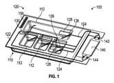
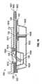
図1に示されるように、例示的な装置は、流体操作のために様々な種類の流体を保持及び方向付ける(又は管理する、又は導く;direct)ための流体カートリッジ100を有して成る。いくつかの例では、流体カートリッジ100は、様々な種類の流体を保持するための1つ以上の流体リザーバーを規定するトレイ110と、トレイ110に操作可能(又は動作可能に;operatively)に取り付けられた積層流体回路120を有して成り、それによって、積層流体回路120がトレイ110中に保持されている様々な種類の流体を1つ以上の流体操作に使用される1つ以上の流体リザーバーから方向付けられる。 As shown in FIG. 1, an exemplary device comprises a
様々な例において、トレイ110は、1つ以上の流体リザーバー112を有して成り、各流体リザーバー112は、指定された流体操作中に使用されることを意図された流体を保持する。いくつかの例では、各流体リザーバー112は、流体リザーバー112が流体を保持するための空間を囲むように、底部及び底部から延在する1つ以上の壁を有して成る。いくつかの例では、リザーバー112は、指定された流体操作に使用される流体の量に応じて可変可能なサイズを有することができる。 In various examples, the
様々な例において、積層流体回路120は、トレイ110上に取り付けられ、流体リザーバー112上に配置されるようになっている実質的に平面の多層基板122を有して成る。様々な例において、積層流体回路120は、基板122内及び積層流体回路120に流体接続された他のデバイスに流体を伝達する多層基板122内に規定された1つ以上のチャネル124を有して成る。様々な例において、積層流体回路120は、流体リザーバー112内へと向きが変更された際に、チャネル124をトレイ110の流体リザーバー112に流体接続する1つ以上の可撓性導管126を有して成る。様々な例において、可撓性導管126は、流体が関連する流体リザーバー112から吸引されることを可能にするようになっており、それによって、流体リザーバー112中に保持された流体は、多層基板122内に配置されたチャネル124に伝達され得る。様々な例において、チャネル124及び可撓性導管126の寸法は、積層流体回路を通る、より効率的な流体の流れを促進するために、高いアスペクト比(例えば、長さ/内径≧5)を有して成り得る。様々な例において、可撓性導管126の長さは、可撓性導管126が流体リザーバー112の底部に到達して、流体リザーバー112中に保持された流体試薬の完全な抽出を確実にするように選択される。いくつかの例において、各可撓性導管126は、その中に1つ以上のチャネル124を有して成ることができる。例えば、各可撓性導管126は、入口チャネル及び出口チャネル等の2つのチャネル124を有して成ることができる。入口チャネルは、別の試薬又は空気等の流体を、対応する流体リザーバー112内に含まれる流体に導入することができる。ある例では、入口チャネルは、混合リザーバーとして流体リザーバー112を利用するために、対応する流体リザーバー112の中へ1つより多い試薬を導入することができる。ある例では、入口チャネルは、対応する流体リザーバー112内に空気を導入することができる。導入された空気は、対応する流体リザーバー112内の流体を泡立たせ、混合し、及び/又は加圧するために使用することができる。ある例では、加熱又は冷却された容積空気を導入して、その中の流体の温度を制御することができる。 In various examples, the
いくつかの例では、可撓性導管126は、多層基板122を通るように形成された1つ以上のカットアウト128によって規定される。各カットアウト128は、それぞれのチャネル124の領域を含む多層基板122の一部分を部分的に取り囲み、その結果、基板122の一部分は、基板122の残余部分から部分的に分離される。各可撓性導管126は、基板122の残余部分から部分的に分離され、それぞれのチャネル124の領域を含む多層基板122の一部分によって規定される。 In some examples, the
積層流体回路120がトレイ110に操作可能に取り付けられる際に、多層基板122は、各カットアウト128及び可撓性導管126を対応する流体リザーバー112上に置くようにトレイ110に整列(又は調整、又は並べる;align)される。様々な例では、可撓性導管126は、多層基板122に対して対応する流体リザーバー112に向かって向きが変更されるように(例えば、手動又は自動装置によって)なっている。対応する流体リザーバー112に向かって向きが変更されると、可撓性導管126は、それぞれのチャネル124をその関連する流体リザーバー112に流体接続する。可撓性導管126の変更された向きは、可撓性導管126内のチャネルが流体リザーバー112内から、可撓性導管126内のチャネルを通って、及び多層基板122の1つ以上のチャネル124中に、流体の流体の流れを可能にするために、手が加えられていない(又は無傷の;intact)ままである間、曲がり(bowing)、屈曲(bending)、湾曲(curving)、又は他の方法で可撓性導管の少なくとも一部分を流体リザーバー112に移動させることを含むことができる。 When the
様々な例において、積層流体回路120は、カットアウト128の1つによって露出されていない流体リザーバー112の1つに流体接続されたポート130を有して成る。いくつかの例において、ポート130は、多層基板122を通るように形成され、及び1つ以上のチャネル124に流体接続された開口部を有して成る。 In various examples, the
様々な例において、流体カートリッジ100は、1つ以上のチャネル124に流体接続された流体デバイス140(例えば、フローセル)を有して成り、その結果、積層流体回路120は、流体が流体リザーバー112と流体デバイス140との間で選択的に伝達されることを可能にする。様々な例において、流体デバイス140は、チャネル124の1つに接続された流体入口142、チャネル124の1つに接続された流体出口144、及び/又は化学的又は生化学的アッセイ又は他の反応等の流体処理が行われることを可能にするために、流体入口142及び流体出口144に流体接続された1つ以上の流体通路(図示せず)を有して成り得る。様々な例において、流体デバイス140は、流体入口142中への様々な種類の流体(例えば、試薬、緩衝液、反応媒体)の導入が、1つ以上の流体通路内で流体処理を受けることを可能にするようになっている。様々な例において、流体デバイス140は、様々な種類の流体が、流体出口144を通る1つ以上の流体通路から洗い流されることを可能にするようにさらになっている。 In various examples, the
流体デバイス140は、積層流体回路120の一体部分であり得て、流体デバイス140は、積層流体回路120に取り外し可能に取り付けられるか、又は結合され得る(例えば、流体入口142と流体出口144を接続する流体コネクタを介して基板122内に規定されたチャネル124へ)、及び/又は流体デバイス140は、積層流体回路120から離隔して位置づけられた別個のデバイスであり得る。 The
いくつかの例では、積層流体回路120は、多層基板122に沿って配置され、動力源から動力を受容するようになっている1つ以上の電気接点150を有して成る。いくつかの例では、積層流体回路120は、可撓性導管126上に配置され、積層流体回路120内及び/又は上に形成された1つ以上の電気経路を介して電気接点150に電気的に接続された1つ以上の電極(図示せず)を有して成る。いくつかの例では、図6~8に示されるように、各可撓性導管126は、開回路の端子として機能する少なくとも2つの電極132a、132bを有して成る。したがって、流体リザーバー112内に可撓性導管126の向きが変更される際に、電極に接触する流体は、流体カートリッジ100に操作可能に関連付けられた処理機器によって、電極が流体レベル(又は流体位、又は流体面、又は流体高さ;flow level)又は流体リザーバー112に保持された流体の存在を検出することを可能にするように、導電体として機能する。例えば、処理機器は、可撓性導管126と電極132a、132bとが液体と接触した際に変化する開回路間の容量信号を検出することによって、液位を容量的に検出することができる。いくつかの例では、可撓性導管126上に配置された電極は、流体リザーバー112内に保持された流体を加熱するための電気ヒーターとして機能する。いくつかの実施形態では、他の電気部品を可撓性導管126内及び/又は上に配置することができる(例えば、センサー、MEMSデバイス等)。 In some examples, the
図2~5は、図1に示された例による積層流体回路120の3層構造を示している。図2に示されるように、積層流体回路120は、互いに重ね合わされた第1の層201、第2の層202、及び第3の層203を有して成る。第1の層201は、第2の層202と第3の層203との間に配置され、第1の層201を通るように形成された1つ以上のスロット204を有して成る。いくつかの例では、第1の層201は、又は1つ以上のスロット204の代わりに、チャネル、くぼみ、又は第1の層201に形成された他の特徴も有して成ることができる。いくつかの例では、部分210、210は、流体デバイス140を形成するために、層201~203のそれぞれの一端でトリミング(又は切り取られる;trimming)される。いくつかの例では、層201~203のそれぞれは、ポリエチレンテレフタレート(PET)、ポリメチルメタクリレート(PMMA)、ポリカーボネート、ポリ塩化ビニル(PVC)、ポリジメチルシロキサン(PDMS)、環状オレフィンコポリマー(COP)等のポリマー材料(例えば、プラスチック)を有して成る。 2 to 5 show a three-layer structure of the
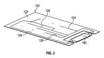
図3を参照すると、第1、第2、及び第3の層201~203は、一体に積層されて、実質的に平面の多層基板122を形成する。いくつかの例では、熱結合(又は熱接合;thermal bonding)、溶剤接合、レーザー溶接、又は層201~203の側面に例えば感圧接着剤を塗布することで層201~203の側面を互いに接着することによって、第1、第2、及び第3の層が一体に積層される。層201~203が一体に積層された後、第2層202及び第3層203は、スロット204及び/又は第1層201に形成された他の特徴を囲み、多層基板122内に規定されたチャネル124を形成する。いくつかの例では、いくつかのチャネル124は、各可撓性導管126のために規定することができる。層201~203が一体に積層されると、トリミングされた部分210、214は、多層基板122の一端に流体デバイス140を形成するように整列される。ある実施形態では、トリミングされた部分210、210は省略され得る。 Referring to FIG. 3, the first, second, and third layers 201-203 are integrally laminated to form a substantially
図4を参照すると、それぞれのチャネル124の領域を含む多層基板122の選択部分は、多層基板122を介してカットアウト128を形成することによって分断される。例示的な例では、カットアウト128は、多層基板122の分断された一部分が多層基板122の残余部分から部分的に分離され、それによって可撓性導管126を形成するように、チャネル124の領域(例えば、端末端(又は末端;terminal end))を部分的に取り囲むように成形(例えば、U字形状)される。各可撓性導管126は、多層基板122の分断された一部分と、そのそれぞれのチャネル124の含まれた領域を有して成る。
図4に示されるように、可撓性導管126は、屈曲のない配置に設定され、可撓性導管126は、多層基板122と実質的に整列したままである(すなわち、同一平面上にある)。いくつかの例では、積層流体回路120がトレイ110からエンド・ユーザーに別々に輸送、又は出荷されている間、可撓性導管126は屈曲のない配置に設定され得る。
いくつかの例では、いくつかのチャネル124は、各可撓性導管126のために規定され得る。Referring to FIG. 4, the selection portion of the
As shown in FIG. 4, the
In some examples, some
図5を参照すると、可撓性導管126は、多層基板122の分断された一部分及びチャネル124の含まれた領域が、残余部分の平面の多層基板122に対して傾斜、湾曲、屈曲(又は曲げ;bent)、又は他の方法で移動するように向きが変更された配置に設定される。積層流体回路120がトレイ110に操作可能に取り付けられて、流体リザーバー112に保持された流体を流体デバイス140に送達すると、可撓性導管126は向きが変更された配置に設定され得る。 Referring to FIG. 5, the
多層基板122内に規定されたチャネル124及び多層基板122の残余部分から部分的に分断された可撓性導管126の詳細が、図6~13に示されている。 Details of the
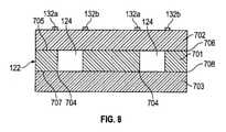
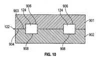
図6は、積層流体回路120の概略部分上面図を示し、可撓性導管126は、多層基板122を通るようにカットアウト128を切断することによって形成される。いくつかの例では、いくつかのチャネル124は、各可撓性導管126のために規定され得る。図7及び図8は、それぞれ、図6の線A-A及びB-Bに沿って取られた多層基板122の3層構造の断面図を示す。図9及び10は、それぞれ、図6の線A-A及びB-Bに沿って取られた多層基板122の2層構造の断面図を示す。 FIG. 6 shows a schematic partial top view of the
図7及び図8に示すように、多層基板122の3層構造の場合、チャネル124は、スロット704を、層701の上面706から第1の下面708まで切断することによって形成される。チャネル124は、第2の層702の合わせ面(又は接着面;mating surface)705を第1の層701の上面706に固定し、第3の層703の合わせ面707を第1の層701の下面708に固定することによって囲まれる。図7を参照すると、各可撓性導管126は、第1、第2、及び第3の層701~703を通るようにカットアウト128を切断することによって形成される。多層基板122の層701~703を通るようにカットアウト128を切断することによって、可撓性導管126の側面712は、多層基板122の残余部分から分離される。いくつかの例では、いくつかのチャネル124は、各可撓性導管126のために規定されることができる。図8を参照すると、チャネル124は、多層基板122の残余部分に沿って可撓性導管126から離隔して延在する。図8に示すように、チャネル124は、第1の層701を通って延在し、第2の層702の合わせ面705及び第3の層703の合わせ面707によって囲まれる、スロット704によって規定される。 As shown in FIGS. 7 and 8, in the case of the three-layer structure of the
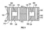
図9及び図10に示すように、多層基板122の2層構造の場合、チャネル124は、第1の層901の合わせ面903に沿って第1の溝906及び第2の層902の合わせ面904に沿って第2の溝908を形成することによって形成される。チャネル124は、チャネル124を規定するために、第1の溝906を第2の溝908と位置合わせする方法で、第1の層901の合わせ面903を第2の層902の合わせ面904に固定することによって囲まれる。いくつかの例では、チャネル124は、第1及び第2の層901、902の合わせ面の一方のみに沿って溝を形成し、溝を他方の層901、902の合わせ面で囲むことによって形成され得る。図9を参照すると、可撓性導管126は、カットアウト128を第1及び第2の層901及び902を通るように切断することによって形成される。カットアウト128を多層基板122の層901、902を通るように切断することによって、可撓性導管126の側面912が、多層基板122の残部から分離される。 いくつかの例では、いくつかのチャネル124は、各可撓性導管126に対して規定されることができる。図10に示されるように、チャネル124は、多層基板122の残余部分に沿って可撓性導管126から離れて延びる。図10に示されるように、チャネル124は、第1及び第2の層901、902の整列された溝906、908によって規定される。 As shown in FIGS. 9 and 10, in the case of the two-layer structure of the
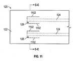
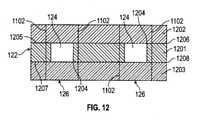
図11は、積層流体回路120の概略部分上面図を示しており、可撓性導管126は、多層基板122内又は多層基板122を介してスコアライン(又は縦溝、又は横溝、又は横線;score line)1102を形成し、チャネル124の領域(例えば、端末端)を部分的に取り囲むことによって形成される。いくつかの実施形態では、スコアライン1102は、積層流体回路120に形成された穿孔又は他の部分的な切り込み、くぼみ等であり得る。いくつかの例では、いくつかのチャネル124は、各可撓性導管126に対して規定されることができる。図12は、図11の線C-Cに沿って取られた多層基板122の3層構造の断面図を示す。図13は、図11の線C-Cに沿って取られた多層基板122の2層構造の断面図を示す。 FIG. 11 shows a schematic partial top view of the
図12に示すように、多層基板122の3層構造の条件下で、チャネル124は、第1の層1201の上面1206から第1の層の下面1208までスロット1204を切断することによって形成される。チャネル124は、第2の層1202の合わせ面1205を第1の層1201の上面1206に固定し、第3の層1203の合わせ面1207を第1の層1201の下面1208に固定することによって囲まれる。可撓性導管126は、多層基板122内にスコアライン1102を形成することによって形成され、スコアライン1102は、一例では、第1、第2、及び第3の層1201~1203のうちの1つ以上を通るように形成される。スコアライン1102は、部分的な溝、穴あきライン、線形インデント、又はライン1102に沿って基板122を局所的に弱くする他の手段を有して成り、スコアライン1102によって部分的に囲まれた多層基板122の一部分が、スコアライン1102が可撓性導管126の側面を規定するように、外力適用時に基板122の残余部分から制御可能に分離されることを可能にする。いくつかの例では、いくつかのチャネル124は、各可撓性導管126のために規定され得る。 As shown in FIG. 12, under the condition of the three-layer structure of the
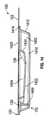
図13に示すように、多層基板122の2層構造の条件下で、チャネル124は、第1の層1301の合わせ面1303に沿って第1の溝1306を形成し、第2の層の合わせ面1304に沿って第2の溝1308を形成することによって形成される。チャネル124は、チャネル124を規定するために、第1の溝1306を第2の溝1308と整列する方法で、第1の層1301の合わせ面1303を第2の層1304の合わせ面1304に固定することによって囲まれる。可撓性導管126は、多層基板122内にスコアライン1102を形成することによって形成され、スコアライン1102は、一例では、第1及び第2の層1301、1302のうちの1つ以上を介して形成される。この場合も、スコアライン1102は、部分的な溝、穴あきライン、線形インデント、又はライン1102に沿って基板122を局所的に弱くする他の手段を有して成り、スコアライン1102によって部分的に囲まれた多層基板122の一部分が、スコアライン1102が可撓性導管126の側面を規定するように、外力適用時に基板122の残余部分から制御可能に分離されることを可能にする。いくつかの例では、いくつかのチャネル124は、各可撓性導管126のために規定され得る。 As shown in FIG. 13, under the condition of the two-layer structure of the
図14及び15に示されるように、いくつかの例では、トレイ110は、第1のリザーバー1402と、第1のリザーバー1402内に配置された1つ以上の第2のリザーバー1404(図示された実施形態では3つ)を有して成る。第1のリザーバー1402は底部1410、底部1410から延在する一組の壁1412、及び壁1412から突出し、第1のリザーバー1402を取り囲むフランジ1414を有して成る。第2のリザーバー1404は、プレート1420を打ち抜くことによって形成され、それによって、各第2のリザーバー1404は、プレート1420の平面から凹んだ底部1422と、底部1422からプレート1420の平面まで延在する一組の壁1424を有して成る。プレート1420は、第1のリザーバー1402の上部に(又は上に;on top of)配置され、フランジ1414によって支持される。それにより、第2のリザーバー1404は、第1のリザーバー1402内に存在する。 As shown in FIGS. 14 and 15, in some examples, the
いくつかの例では、第1のリザーバー1402は、第2のリザーバー1404のそれぞれよりも大量の流体を保持する。いくつかの例では、第1のリザーバー1402は、第2のリザーバーで保持される流体の種類よりもより頻繁に又は広範囲に使用される水和緩衝液又は洗浄溶液等の流体を保持する。いくつかの例では、第2のリザーバー1404は、第1のリザーバー1402に貯蔵された水和緩衝液の導入によって乾燥状態から液体状態に変換されるようになっている凍結乾燥試薬を保持する。いくつかの例では、トレイ110がその目的地に輸送されている間、及びトレイ110が最初に多層基板122に接続されている際、第2のリザーバー1404は空であり得る。いくつかの例では、空の第2の流体リザーバー114が流体操作中に2つ以上の他の流体リザーバーから試薬流体を受容するように、空の第2の流体リザーバー1404が混合ウェル(又は混合穴;mixing well)として使用され得る。いくつかの例では、空の第2の流体リザーバー1404は、空の第2の流体リザーバー114が、流体操作中に別の流体リザーバーに貯蔵される試薬流体の一定分量を保持するように、ステージングウェル(又はステージング穴;staging well)(例えば、キャッシュリザーバー(又は貯蔵リザーバー(cache reservoir)))として使用され得る。いくつかの例では、第2の流体リザーバー1404は、その中に密封された(例えば、貫通可能なホイルによってその中に密封された)液体試薬を有して成ることができる。 In some examples, the
いくつかの例では、第1のリザーバー1402は、可撓性導管126のいずれにも流体接続されていないが、ポート130を介してチャネル124に流体接続されている。いくつかの例では、トレイ110は、導管1406が第1のリザーバー1402をチャネル124に流体接続するように、積層流体回路110のポート130に接続され、第1のリザーバー1402内に延在する導管1406を有して成る。いくつかの例では、各第2のリザーバー1404は、積層流体回路120の基板122を介して形成される対応するカットアウト128の下に配置され、対応する可撓性導管126によってチャネル124に流体接続されている。いくつかの例では、第1のリザーバー1402は、可撓性導管126に流体接続されている。 In some examples, the
図16は、一例による流体カートリッジ100の側面断面図を示す。実例となる例では、積層流体回路120は、第1の層1601、第2の層1602、及び第3の層1603を有して成る。第2の層1602は、第1の層1601と第3の層1603との間に配置される。第2の層1602は、第1の層1601及び第3の層1603によって囲まれる1つ以上のチャネル124を形成する1つ以上のスロットを有して成る。 FIG. 16 shows a side sectional view of the
図2及び図3に示される例と同様に、図16のトレイ110は、第1のリザーバー1402及び第1のリザーバー1402内に配置された第2のリザーバー1404を有して成る。第1のリザーバー1402は、水和緩衝液1622を保持し得て、流体ポート130に接続された導管1406によって積層流体回路120に流体接続される。第2のリザーバー1404は、凍結乾燥試薬1624を乾燥状態で保持し得る。第2のリザーバー1404は、ホイル1620が水分を第2のリザーバー1404に入ることを防ぎ、それによって凍結乾燥試薬1624を乾燥状態に維持するように、第2の流体リザーバー1404の開口部を覆うホイル1620によって密封され得る。いくつかの例では、第2の流体リザーバー1404は、その中に密封された(例えば、貫通可能なホイル1620によってその中に密封された)液体試薬を有して成るができる。 Similar to the example shown in FIGS. 2 and 3, the
様々な例において、図16に示されるように、流体カートリッジ100は、積層流体回路120上に配置され、トレイ110の対向側にある剛性カバー1610を有して成り得る。いくつかの例において、剛性カバー1610は、剛性カバー1610が積層流体回路120の多層基板122に剛性を提供するように、射出成形プラスチック材料から構成される。 In various examples, as shown in FIG. 16, the
いくつかの例では、剛性カバー1610は、カバー1610の平面1611に対して枢動するようになっているパンチ1612を有して成る。カバー1610が積層流体回路120に操作可能に取り付けられている場合、カバー1610は、対応する可撓性導管126の少なくとも一部分の上にパンチ1612を置く方法で多層基板122に整列される。カバー1610が多層基板122上に整列されると、パンチ1612を作動され得る(例えば、手動又は機械によって)、可撓性導管126を多層基板122から離隔して、本例では流体リザーバー1404等の流体リザーバーに向きが変更させる。可撓性導管126の向きを変更させている間、パンチ1612自体は、可撓性導管126が第2の流体リザーバー1404を覆うホイル1620を貫通するか、又は貫通させ、その結果、可撓性導管126は、貫通ホイル1620を通って向きが変更され、チャネル124を流体接続する。いくつかの例では、いくつかのチャネル124は、各可撓性導管126にために規定され得る。 In some examples, the
様々な例において、カバー1610は、第2の流体リザーバー1404とその対応するチャネル124との間の流れを制御するために、チャネル124及び第2の流体リザーバー1404の1つに操作可能に関連付けられたバルブ1614を有して成る。いくつかの例では、バルブ1614は、小さな丸いディップ(又は凹み、又は傾斜;dip)を有して成るピンチバルブであり、対応するチャネル124を密閉するために(例えば、外部ピンチロッドを用いて)圧縮され得る。
流体カートリッジの組み立て方法In various examples, the
How to assemble the fluid cartridge
様々な例によれば、図17は、積層流体回路120及び少なくとも1つの流体リザーバー112を有して成る流体カートリッジ100を組み立てるための方法1700を示している。 According to various examples, FIG. 17 shows a
図17に示されるように、方法1700は、基板材料の層の表面又は基板材料の層を介するスロットに溝を形成する工程1702を含む。図7、8、及び12を参照すると、多層基板122の3層構造の条件下で、工程1702は、スロット704、1204を層701、1201を介して切断することを含む。いくつかの例では、スロット704、1204を形成する工程1702は、レーザーを使用して層701、1201を切り開くことを含む。図9、10、及び13を参照すると、多層基板122の2層構造の条件下で、工程1702は、第1の層901、1301の合わせ面903、1303に第1の溝906、1306を、及び任意で、第2の層902、1302の合わせ面904、1304に第2の溝908、1308形成することを含む。 As shown in FIG. 17,
図17を参照すると、方法1700は、1つ以上の層を、溝又はスロットを有して成る層に積層して実質的に平面の多層基板122を形成し、溝又はスロットを囲んでチャネル124を形成する工程1704を含む。いくつかの例では、層は、ポリマー又はプラスチック材料を有して成り、工程1704は、様々なプラスチック層を一体に接着又は熱的に結合することを含む。 Referring to FIG. 17,
図7、8、及び12を参照すると、多層基板122の3層構造の条件下で、工程1704は、層702、1202(上層)及び層703、1203(下層)を層701、1201(中間層)に積層することを含み 、それによって、層701、1201に形成されたスロット704、1104を取り囲み、層702、1202及び層703、1203は、チャネル124を形成する。 Referring to FIGS. 7, 8 and 12, under the condition of the three-layer structure of the
図9、10、及び13を参照すると、多層基板122の2層構造の条件下で、工程1704は、第1の層901、1301を第2の層902、1302に積層して、それによって、第1の層901、1301の合わせ面903、1303に沿って形成された第1の溝906、1306が、第2の層902、1302の合わせ面904、1304に沿って形成された第2の溝908、1308と整列してチャネル124を形成する。 Referring to FIGS. 9, 10 and 13, under the condition of the two-layer structure of the
図17を参照すると、方法1700は、チャネル124の領域を含む多層基板122の一部分を分断する工程1706を含み、その結果、分断された一部分は、多層基板122の残余部分から部分的に分離された又は分離可能である、可撓性導管126を形成する。 Referring to FIG. 17,
図6-10を参照すると、いくつかの例では、分断工程1706は、多層基板122の1つ以上の層701~703、901~902を通るようにカットアウト128を形成することを含む。図6に示されるように、各カットアウト128は、多層基板122の分断された一部分を部分的に取り囲むように形作られる、可撓性導管126を形成する。いくつかの例では、カットアウト128は、パンチを有して成るダイカッター(図示せず)を使用し、パンチを多層基板122を通るように押すことによって形成され、カットアウト128を形成する、又は多層基板122に溝及びカットアウトを切断するレーザーカッターによってカットアウト128を形成する。 Referring to FIG. 6-10, in some examples, the
図11~13を参照すると、いくつかの例では、分断工程1706は、スコアライン1102を多層基板122に形成することを含む。図11に示されるように、各スコアライン1102は、チャネル124の領域を含む多層基板122の分断された一部分を部分的に囲むように形作られ、それによって、スコアライン1102が、多層基板122の分断された一部分に外力を加えると、多層基板122の分断された一部分が多層基板122の残余部分から部分的に分離することを可能にする。いくつかの実施形態では、ミシン目又は他の部分的な分断は、スコアライン1102の代わりに、又はそれに加えて使用することができる。 Referring to FIGS. 11-13, in some examples, the
図17を参照すると、方法1700は、流体リザーバー112が可撓性導管126の下に配置されるように、多層基板122を流体リザーバー112に接続する工程1708を含む。いくつかの例では、接続の工程1708は、複数の流体リザーバー112を有して成るトレイ110上に多層基板122を取り付けることを含み、及び工程1708は、各可撓性導管126を対応する流体リザーバー112の少なくとも一部分の上に置く方法で、多層基板122をトレイ110に整列することをさらに含む。いくつかの例では、多層基板122は、多層基板122の底面を接着剤又は感圧接着剤でトレイ110の上面に接着する、又は多層基板122をトレイ110の上面にレーザー溶接する等、様々なプロセスによってトレイ110に取り付けられ得る。 Referring to FIG. 17,
図17を参照すると、方法1700は、多層基板を剛性カバー1610に接続する工程1710を含み、可撓性導管126の向きが変更されるようになっているパンチ1612を含み得る。いくつかの例では、工程1710は、可撓性導管126の少なくとも一部分の上にパンチ1612を置くように、多層基板122で整列するカバー1610を覆うことを含む。 Referring to FIG. 17,
図17を参照すると、方法1700は、例えば、可撓性導管126に対してパンチ1612を作動させることによって、多層基板122に対して流体リザーバー112内へと可撓性導管126の向きが変更される工程1712を含む。いくつかの例では、工程1712は、流体リザーバー112を覆うホイル1620を貫通することをさらに含み、それによって、可撓性導管126は、貫通したホイル1620を通って向きが変更され、多層基板122内のチャネル124を流体リザーバー112に流体接続する。リザーバー112が輸送及び保管中に乾燥したままである場合、工程1712が製造プロセス中に行われるか、又は工程1712は流体カートリッジ100を使用する直前に処理機器によって実行され得る。 Referring to FIG. 17,
前述の概念及び以下でより詳細に論じられる追加の概念のすべての組み合わせ(そのような概念が相互に矛盾しないという条件で)は、本明細書に開示される本発明の主題の一部であると考えられることを理解されたい 特に、本開示の終わりに現れるクレームされた主題のすべての組み合わせは、本明細書に開示された本発明の主題の一部であると考えられる。 参照により組み込まれる任意の開示にも現れる可能性のある、本明細書で明示的に使用される用語は、本明細書で開示される特定の概念と最も一致する意味を与えられるべきであることも理解されたい。 All combinations of the above concepts and the additional concepts discussed in more detail below (provided that such concepts are consistent with each other) are part of the subject matter of the invention disclosed herein. It should be understood that, in particular, all combinations of claimed subjects appearing at the end of this disclosure are considered to be part of the subject matter of the invention disclosed herein. The terms explicitly used herein, which may also appear in any disclosure incorporated by reference, should be given the meaning most consistent with the particular concepts disclosed herein. Please also understand.
実施形態 Embodiment
実施形態1.
装置であって、流体リザーバー、及び流体リザーバー上に位置づけられた積層流体回路を有して成り、積層流体回路は、2つ以上の層、1つ以上のチャネル、可撓性導管を有して成り、2つ以上の層は、実質的に平面の基板を規定するために一体に積層され、1つ以上のチャネルは、基板内に規定され、及び可撓性導管は、基板の残余部分から部分的に分離された又は分離可能な、1つ以上のチャネルの少なくとも1つの領域を含む基板の一部分によって規定され、可撓性導管は、基板の一部分及びチャネルの含まれた領域を有して成り、可撓性導管は、可撓性導管が少なくとも1つのチャネルを流体リザーバーに流体接続するように、平面の基板に対して流体リザーバーに向かって向きが変更可能である、
装置。Embodiment 1.
A device consisting of a fluid reservoir and a laminated fluid circuit located on the fluid reservoir, the laminated fluid circuit having two or more layers, one or more channels, flexible conduits. The two or more layers are laminated integrally to define a substantially flat substrate, one or more channels are defined within the substrate, and the flexible conduit is from the rest of the substrate. Defined by a portion of the substrate containing at least one region of one or more channels that is partially separated or separable, the flexible conduit has a portion of the substrate and a region containing the channel. Thus, the flexible conduit can be oriented towards the fluid reservoir with respect to the planar substrate such that the flexible conduit fluidly connects at least one channel to the fluid reservoir.
Device.
実施形態2.
基板が、基板を通るように形成されたカットアウトを有して成り、カットアウトが、チャネルの領域を含む基板の一部分を部分的に取り囲んでいる、実施形態1に記載の装置。Embodiment 2.
The apparatus of embodiment 1, wherein the substrate comprises a cutout formed to pass through the substrate, wherein the cutout partially surrounds a portion of the substrate, including a region of the channel.
実施形態3.
基板が、チャネルの領域を含む基板の一部分を部分的に囲むスコアラインを有して成り、スコアラインは、基板の一部分が、基板の一部分に対する外力の適用時に基板の残余部分から部分的に分離することを可能にする、実施形態1に記載の装置Embodiment 3.
The substrate consists of a scoreline that partially surrounds a portion of the substrate that includes the area of the channel, where the scoreline partially separates the portion of the substrate from the rest of the substrate when an external force is applied to the portion of the substrate. The apparatus according to Embodiment 1, which makes it possible to do so.
実施形態4.
2つ以上の層が、第1の層、第2の層、及び第3の層を有して成り、第1の層が、第2の層と第3の層との間に配置され、及び第2の層と第3の層とによって対向側が覆われた際に1つ以上のチャネルを形成する少なくとも1つのスロットを有して成る、実施形態1に記載の装置。Embodiment 4.
Two or more layers consist of a first layer, a second layer, and a third layer, the first layer being arranged between the second layer and the third layer. And the apparatus according to embodiment 1, comprising at least one slot forming one or more channels when the opposite side is covered by a second layer and a third layer.
実施形態5.
2つ以上の層が、第1の層及び第1の層に積層された第2の層を有して成り、少なくとも第1の層は、その表面に形成された少なくとも1つの溝を有して成り、少なくとも1つの溝は、第2の層によって覆われた際に1つ以上のチャネルを形成する、実施形態1に記載の装置。Embodiment 5.
Two or more layers consist of a first layer and a second layer laminated on the first layer, at least the first layer having at least one groove formed on its surface. The device of embodiment 1, wherein at least one groove forms one or more channels when covered by a second layer.
実施形態6.
基板が、互いに接着又は熱結合された高分子材料の2つ以上の層を有して成る、実施形態1に記載の装置。Embodiment 6.
The apparatus according to embodiment 1, wherein the substrates have two or more layers of a polymeric material bonded or thermally bonded to each other.
実施形態7.
可撓性導管上に配置された1つ以上の電極をさらに有して成る、実施形態1に記載の装置。
The device of embodiment 1, further comprising one or more electrodes disposed on a flexible conduit.
実施形態8.
1つ以上の電極は、流体リザーバーに保持された流体の流体レベルを検出すること、流体リザーバーに保持された流体の存在を検出すること、又は流体リザーバーに保持された流体を加熱することの1つ以上のためのものである、実施形態7に記載の装置。Embodiment 8.
One or more electrodes can detect the fluid level of the fluid held in the fluid reservoir, detect the presence of the fluid held in the fluid reservoir, or heat the fluid held in the fluid reservoir. The device according to
実施形態9.
流体リザーバーと少なくとも1つのチャネルとの間の流れを制御するための、少なくとも1つのチャネル及び流体リザーバーと操作可能に関連付けられたバルブをさらに有して成る、実施形態1に記載の装置。Embodiment 9.
The device of embodiment 1, further comprising at least one channel and a valve operably associated with the fluid reservoir for controlling the flow between the fluid reservoir and the at least one channel.
実施形態10.
流体回路上に配置され、平面の基板から離隔して流体リザーバー内へと可撓性導管の向きを変更させるためのパンチを含む剛性カバーをさらに有して成る、実施形態1に記載の装置。Embodiment 10.
The apparatus of embodiment 1, further comprising a rigid cover that is disposed on the fluid circuit and includes a punch for reorienting the flexible conduit away from the flat substrate and into the fluid reservoir.
実施形態11.
流体リザーバーが密封されるように流体リザーバーの開口部を覆う貫通可能なホイルをさらに有して成り、
パンチは、可撓性導管を流体リザーバーに流体接続するために、ホイルを貫通し、貫通したホイルを通して可撓性導管の向きを変更させる、実施形態10に記載の装置。Embodiment 11.
It further has a penetrating foil covering the opening of the fluid reservoir so that the fluid reservoir is sealed,
The device according to embodiment 10, wherein the punch penetrates a foil and redirects the flexible conduit through the pierced foil in order to fluidly connect the flexible conduit to the fluid reservoir.
実施形態12.
方法であって、第1の層にチャネルを形成し、1つ以上の層を第1の層に積層し、平面の多層基板を形成し、それによって、チャネルを基板内に規定すること、及びチャネルの領域を含む基板の一部分を分断し、それによって、文壇された一部分を基板の残余部分から部分的に分離させ又は分離可能とし、基板の一部分及びチャネルの含まれた領域を含む可撓性導管を形成すること、を含み可撓性導管は、平面の基板に対して向きが変更可能となっている、
方法。Embodiment 12.
The method is to form a channel in the first layer and stack one or more layers on the first layer to form a planar multilayer substrate, thereby defining the channel within the substrate, and A part of the substrate containing the area of the channel is fragmented, thereby allowing the literary part to be partially separated or separable from the rest of the substrate, and the flexibility to include the part of the substrate and the area containing the channel. Flexible conduits are reorientable with respect to a flat substrate, including forming a conduit.
Method.
実施形態13.
第1の層にチャネルを形成する工程が、第1の層の表面に溝を形成することを含み、第1の層に積層された1つ以上の層が溝を囲む、実施形態12に記載の方法。Embodiment 13.
12. The step of forming a channel in the first layer comprises forming a groove on the surface of the first layer, wherein one or more layers laminated on the first layer surround the groove. the method of.
実施形態14.
第1の層にチャネルを形成する工程が、第1の層を介してスロットを形成することを含み、及び第1の層に積層された1つ以上の層がスロットを囲む、実施形態12に記載の方法。Embodiment 14.
In Embodiment 12, the step of forming a channel in the first layer comprises forming a slot through the first layer, and one or more layers laminated on the first layer surround the slot. The method described.
実施形態15.
基板の一部分を分断する工程が、チャネルの領域を含む基板の一部分を部分的に取り囲む基板を通るカットアウトを形成することを含む、実施形態12に記載の方法。Embodiment 15.
12. The method of embodiment 12, wherein the step of dividing a portion of the substrate comprises forming a cutout through the substrate that partially surrounds the portion of the substrate, including the region of the channel.
実施形態16.
基板の一部分を分断する工程が、チャネルの領域を含む基板の一部分を部分的に囲むスコアラインを形成することを含み、
スコアラインが、基板の一部分への外力の適用際に、基板の残余部分から基板の一部分を部分的に分離することを可能にする、実施形態12に記載の方法。Embodiment 16.
The process of dividing a portion of the substrate comprises forming a scoreline that partially surrounds the portion of the substrate, including the area of the channel.
12. The method of embodiment 12, wherein the scoreline allows a portion of the substrate to be partially separated from the rest of the substrate when an external force is applied to the portion of the substrate.
実施形態17.
可撓性導管はその向きが変更されていない配置に設定されている間に、流体リザーバーが多層基板及び可撓性導管の下方に配置されるように、多層基板を流体リザーバーに接続することをさらに含む、実施形態12に記載の方法。Embodiment 17.
Connecting the multilayer board to the fluid reservoir so that the fluid reservoir is located below the multilayer board and the flexible conduit while the flexible conduit is set to its unaltered arrangement. The method according to embodiment 12, further comprising.
実施形態18.
可撓性導管内のチャネルの含まれた領域が、基板内に規定されたチャネルを流体リザーバーに流体接続するように、可撓性導管を流体リザーバーに向かって基板に対して向きを変更させることをさらに含む、実施形態17に記載の方法。Embodiment 18.
Reorienting the flexible conduit towards the fluid reservoir so that the area containing the channel in the flexible conduit fluidly connects the channels defined in the substrate to the fluid reservoir. The method according to embodiment 17, further comprising.
実施形態19.
可撓性導管の向きを変更させる工程の後に、流体リザーバーに保持された流体を、可撓性導管内のチャネルの含まれた領域を通じて、基板に規定されたチャネルに吸引することをさらに含む、実施形態18に記載の方法。Embodiment 19.
After the step of reorienting the flexible conduit, further comprising sucking the fluid held in the fluid reservoir through the included region of the channel in the flexible conduit into the channel defined on the substrate. The method according to embodiment 18.
実施形態20.
可撓性導管の向きを変更させる工程の後に、基板内に規定されたチャネル及び可撓性導管内のチャネルの含まれた領域を通じて、流体リザーバーに流体を導入することをさらに含む、実施形態18に記載の方法。20.
Embodiment 18 further comprises introducing fluid into the fluid reservoir through a defined channel within the substrate and a region containing the channel within the flexible conduit after the step of reorienting the flexible conduit. The method described in.
実施形態21.
多層基板を剛性カバーに接続することをさらに含む、実施形態12に記載の方法。21. Embodiment 21.
12. The method of embodiment 12, further comprising connecting the multilayer board to a rigid cover.
実施形態22.
剛性カバーは、平面の基板に対して可撓性導管の向きを変更させるためのパンチを有して成る、実施形態18に記載の方法。Embodiment 22.
18. The method of embodiment 18, wherein the rigid cover comprises a punch for reorienting the flexible conduit with respect to a flat substrate.
実施形態23.
第1の層及び第1の層に積層された1つ以上の層は、高分子材料の2つ以上を有して成り、1つ以上の層を第1の層に積層する工程は、2つ以上の層を一体に接着又は熱結合することを含む、実施形態16に記載の方法。23.
The first layer and one or more layers laminated on the first layer are composed of two or more polymer materials, and the step of laminating one or more layers on the first layer is 2. 16. The method of embodiment 16, comprising bonding or thermally bonding one or more layers together.
実施形態24.
可撓性導管を形成する基板の一部分に電極を適用することをさらに含む、実施形態12に記載の方法。Embodiment 24.
12. The method of embodiment 12, further comprising applying the electrode to a portion of the substrate forming the flexible conduit.
実施形態25.
装置であって、2つ以上の層、1つ以上のチャネル、及び可撓性導管を有して成り、2つ以上の層は、実質的に平面の基板を規定するために一体に積層され、1つ以上のチャネルは、基板内に規定され、可撓性導管は、基板の残余部分から部分的に分離された又は分離可能な、1つ以上のチャネルの少なくとも1つの領域を含む基板の一部分によって規定され、基板の一部分及びチャネルの含まれる領域を含み、可撓性導管は、平面の基板に対して向きが変更可能となっている、
装置。Embodiment 25.
The device comprises two or more layers, one or more channels, and a flexible conduit, the two or more layers being integrally laminated to define a substantially planar substrate. One or more channels are defined within the substrate and the flexible conduit is a substrate containing at least one region of the one or more channels that is partially separated or separable from the rest of the substrate. Defined by a portion, including a portion of the substrate and the area containing the channel, the flexible conduit is rotatable with respect to the planar substrate.
Device.
実施形態26.
2つ以上の層が、第1の層、第2の層、及び第3の層を有して成り、第1の層が、第2の層と第3の層との間に配置され、第2の層と第3の層とによって対向側が覆われた際に、1つ以上のチャネルを形成する少なくとも1つのスロットを有して成る、実施形態25に記載の装置。Embodiment 26.
Two or more layers consist of a first layer, a second layer, and a third layer, the first layer being arranged between the second layer and the third layer. 25. The apparatus of embodiment 25, comprising at least one slot forming one or more channels when the opposite side is covered by a second layer and a third layer.
実施形態27.
2つ以上の層が、第1の層及び第1の層に積層された第2の層を有して成り、少なくとも第1の層が、その表面に形成され、第2の層で覆われた際に、1つ以上のチャネルを形成する少なくとも1つの溝を有して成る、実施形態25に記載の装置。Embodiment 27.
Two or more layers consist of a first layer and a second layer laminated on the first layer, at least the first layer is formed on its surface and covered with the second layer. 25. The apparatus of embodiment 25, comprising at least one groove forming one or more channels upon occurrence.
実施形態28.
流体リザーバーをさらに有して成り、及び可撓性導管は、基板内に規定された少なくとも1つのチャネルを流体リザーバーに流体接続するために流体リザーバーに向かって向きが変更可能となるように、基板が流体リザーバー上に位置づけられ、可撓性導管は、流体リザーバーに保持された流体を基板で規定されたチャネルに吸引するための第1のチャネル、及び流体を流体リザーバーに導入するための第2のチャネルを有して成る、実施形態25に記載の装置。Embodiment 28.
The substrate further comprises a fluid reservoir, and the flexible conduit is rotatable towards the fluid reservoir to fluidly connect at least one channel defined within the substrate to the fluid reservoir. Is located on the fluid reservoir, the flexible conduit is a first channel for sucking the fluid held in the fluid reservoir into the channel defined by the substrate, and a second channel for introducing the fluid into the fluid reservoir. 25. The apparatus of embodiment 25, comprising a channel of.
実施形態29.
流体リザーバー内に保持された流体の存在を検出するために可撓性導管に配置されたセンサーをさらに有して成る、実施形態28に記載の装置。Embodiment 29.
28. The device of embodiment 28, further comprising a sensor located in a flexible conduit to detect the presence of fluid retained in the fluid reservoir.
実施形態30.
動力源から動力を受容するために多層基板に沿って配置された1つ以上の電気接点、及び
可撓性導管に配置され、1つ以上の電気接点に電気的に接続された1つ以上の電極をさらに有して成る、実施形態25に記載の装置。30.
One or more electrical contacts located along a multilayer substrate to receive power from a power source, and one or more electrical contacts located in a flexible conduit and electrically connected to one or more electrical contacts. 25. The device of embodiment 25, further comprising an electrode.
実施形態31.
可撓性導管が、その向きが変更されていない位置と1つ以上の向きが変更された位置との間で向きが変更可能となっており、
可撓性導管は、向きが変更されていない位置で基板と実質的に同一平面上にあり、可撓性導管は、1つ以上の向きが変更された位置で基板に対して傾斜、湾曲、又は屈曲している、実施形態25に記載の装置。Embodiment 31.
The flexible duct can be reoriented between its unaltered position and one or more reoriented positions.
The flexible conduit is substantially coplanar with the substrate in an unaltered position, and the flexible conduit is tilted, curved, with respect to the substrate in one or more oriented positions. 25. The device according to embodiment 25, which is bent or bent.
本開示の主題は、特徴の様々な組み合わせ及びサブコンビネーションを含む特定の例示的な例を参照してかなり詳細に説明及び示されているが、当業者は、他の例及びその変形及び修正を容易に理解するであろう。本開示の範囲内に含まれるもの。さらに、そのような例、組み合わせ、及びサブコンビネーションの説明は、クレームされた主題が、クレームに明示的に記載されたもの以外の特徴又は特徴の組み合わせを必要とすることを伝えることを意図していない。したがって、本開示の範囲は、以下の添付の特許請求の範囲の精神及び範囲内に含まれるすべての修正及び変形を含むことを意図している。The subject matter of the present disclosure is described and presented in considerable detail with reference to specific exemplary examples, including various combinations and subcombinations of features, although those skilled in the art will make other examples and modifications and modifications thereof. It will be easy to understand. Included within the scope of this disclosure. Further, the description of such examples, combinations, and sub-combinations is intended to convey that the claimed subject matter requires features or combinations of features other than those expressly stated in the claim. do not have. Accordingly, the scope of this disclosure is intended to include all modifications and modifications contained within the spirit and scope of the appended claims below.
Claims (31)
Translated fromJapanese前記流体リザーバー上に位置づけられた積層流体回路を有して成り、
前記積層流体回路は、2つ以上の層、1つ以上のチャネル、及び可撓性導管を有して成り、
前記2つ以上の層は、実質的に平面の基板を規定するために一体に積層され、
前記1つ以上のチャネルは、前記基板内に規定され、
前記可撓性導管は、前記基板の残余部分から部分的に分離された又は分離可能な、前記1つ以上の前記チャネルの少なくとも1つの領域を含む前記基板の一部分によって規定され、前記可撓性導管は、前記基板の前記一部分及び前記チャネルの前記含まれる領域を含み、
前記可撓性導管は、前記可撓性導管が前記少なくとも1つのチャネルを前記流体リザーバーに流体接続するように、前記流体リザーバーに向かって前記平面の基板に対して向きが変更可能となっている、
装置。It consists of a fluid reservoir and a laminated fluid circuit located on the fluid reservoir.
The laminated fluid circuit comprises two or more layers, one or more channels, and a flexible conduit.
The two or more layers are integrally laminated to define a substantially flat substrate.
The one or more channels are defined within the substrate.
The flexible conduit is defined by a portion of the substrate comprising at least one region of the one or more channels that is partially separated or separable from the rest of the substrate. The conduit comprises said portion of the substrate and said included region of the channel.
The flexible conduit is rotatable with respect to the planar substrate towards the fluid reservoir such that the flexible conduit fluidly connects the at least one channel to the fluid reservoir. ,
Device.
前記カットアウトが、前記チャネルの前記領域を含む前記基板の前記一部分を部分的に取り囲んでいる、請求項1に記載の装置。The substrate comprises a cutout formed to pass through the substrate.
The device of claim 1, wherein the cutout partially surrounds said portion of the substrate, including said region of the channel.
前記スコアラインは、前記基板の前記一部分が、前記基板の前記一部分に対する外力の適用時に前記基板の前記残余部分から部分的に分離することを可能にする、請求項1に記載の装置。The substrate comprises a scoreline that partially surrounds the portion of the substrate that includes the region of the channel.
The apparatus of claim 1, wherein the scoreline allows the portion of the substrate to be partially separated from the residual portion of the substrate when an external force is applied to the portion of the substrate.
前記第1の層が、前記第2の層と前記第3の層との間に配置され、及び前記第2の層と前記第3の層とによって対向側が覆われた際に1つ以上のチャネルを形成する少なくとも1つのスロットを有して成る、請求項1に記載の装置。The two or more layers are composed of a first layer, a second layer, and a third layer.
One or more when the first layer is disposed between the second layer and the third layer and the opposite side is covered by the second layer and the third layer. The device of claim 1, comprising at least one slot forming a channel.
少なくとも前記第1の層は、その表面に形成された少なくとも1つの溝を有して成り、
前記少なくとも1つの前記溝は、前記第2の層によって覆われた際に前記1つ以上のチャネルを形成する、請求項1に記載の装置。The two or more layers are composed of a first layer and a second layer laminated on the first layer.
At least the first layer comprises at least one groove formed on its surface.
The device of claim 1, wherein the at least one groove forms the one or more channels when covered by the second layer.
前記パンチは、前記可撓性導管を前記流体リザーバーに流体接続するために、前記ホイルを貫通し、前記貫通されたホイルを通るように前記可撓性導管の向きを変更させる、請求項10に記載の装置。It further comprises a penetrating foil covering the opening of the fluid reservoir so that the fluid reservoir is sealed.
13. The device described.
前記チャネルの領域を含む前記基板の一部分を分断し、それによって、前記分断された一部分が前記基板の残余部分から部分的に分離させ又は分離可能とし、前記基板の前記一部分及び前記チャネルの前記含まれた領域を含む可撓性導管を形成すること、を含み
前記可撓性導管は、前記平面の基板に対して向きが変更可能となっている、
方法。A channel is formed in the first layer, and one or more layers are laminated on the first layer to form a planar multilayer substrate, thereby defining the channel within the substrate, and the region of the channel. A portion of the substrate comprising the Including forming a flexible conduit, said flexible conduit is rotatable with respect to the planar substrate.
Method.
前記スコアラインが、前記基板の前記一部分への外力の適用時に、前記基板の前記残余部分から部分的に分離することを可能にする、請求項12に記載の方法。The step of dividing a portion of the substrate comprises forming a scoreline that partially surrounds the portion of the substrate, including the region of the channel.
12. The method of claim 12, wherein the scoreline is allowed to be partially separated from the residual portion of the substrate when an external force is applied to the portion of the substrate.
2つ以上の層、1つ以上のチャネル、及び可撓性導管を有して成り、
前記2つ以上の層は、実質的に平面の基板を規定するために一体に積層され、
前記1つ以上のチャネルは、前記基板内に規定され、
前記可撓性導管は、前記基板の残余部分から部分的に分離された又は分離可能な、前記1つ以上のチャネルの少なくとも1つの領域を含む前記基板の一部分によって規定され、前記基板の前記一部分及び前記チャネルの前記含まれた領域を含み、前記可撓性導管は、前記平面の基板に対し向きが変更可能となっている、
装置。It ’s a device,
It consists of two or more layers, one or more channels, and a flexible conduit.
The two or more layers are integrally laminated to define a substantially flat substrate.
The one or more channels are defined within the substrate.
The flexible conduit is defined by a portion of the substrate comprising at least one region of the one or more channels, partially separated or separable from the rest of the substrate, said portion of the substrate. And the included region of the channel, the flexible conduit is rotatable with respect to the planar substrate.
Device.
前記第1の層が、前記第2の層と前記第3の層との間に配置され、前記第2の層と前記第3の層とによって対向側が覆われた際に、1つ以上のチャネルを形成する少なくとも1つのスロットを有して成る、請求項25に記載の装置。The two or more layers are composed of a first layer, a second layer, and a third layer.
When the first layer is arranged between the second layer and the third layer and the opposite side is covered by the second layer and the third layer, one or more. 25. The apparatus of claim 25, comprising at least one slot forming a channel.
前記可撓性導管は、前記基板内に規定された少なくとも1つのチャネルを前記流体リザーバーに流体接続するために前記流体リザーバーに向かって向きが変更可能となるように、前記基板が前記流体リザーバー上に位置づけられ、
前記可撓性導管は、前記流体リザーバーに保持された流体を前記基板で規定された前記チャネルに吸引するための第1のチャネル、及び流体を前記流体リザーバーに導入するための第2のチャネルを有して成る、請求項25に記載の装置。It further comprises a fluid reservoir, and the flexible conduit is rotatable towards the fluid reservoir to fluidly connect at least one channel defined within the substrate to the fluid reservoir. As such, the substrate is positioned on the fluid reservoir and
The flexible conduit has a first channel for sucking the fluid held in the fluid reservoir into the channel defined by the substrate and a second channel for introducing the fluid into the fluid reservoir. 25. The apparatus of claim 25.
前記可撓性導管に配置され、前記1つ以上の電気接点に電気的に接続された1つ以上の電極をさらに有して成る、請求項25に記載の装置。One or more electrical contacts arranged along the multilayer substrate to receive power from a power source, and one electrically connected to the flexible conduit and electrically connected to the one or more electrical contacts. 25. The apparatus of claim 25, further comprising one or more electrodes.
前記可撓性導管は、前記向きが変更されていない位置で前記基板と実質的に同一平面上にあり、前記可撓性導管は、前記1つ以上の向きが変更された位置で前記基板に対して傾斜、湾曲、又は屈曲している、
請求項25に記載の装置。The flexible duct can be reoriented between a position in which it has not been reoriented and a position in which one or more have been reoriented.
The flexible conduit is substantially coplanar with the substrate in a position where the orientation has not been changed, and the flexible conduit is attached to the substrate in a position where the one or more orientations have been changed. On the other hand, it is tilted, curved, or bent.
25. The apparatus of claim 25.
Applications Claiming Priority (3)
| Application Number | Priority Date | Filing Date | Title |
|---|---|---|---|
| US201862768278P | 2018-11-16 | 2018-11-16 | |
| US62/768,278 | 2018-11-16 | ||
| PCT/US2019/061461WO2020102521A1 (en) | 2018-11-16 | 2019-11-14 | Laminate fluidic circuit for a fluid cartridge |
Publications (2)
| Publication Number | Publication Date |
|---|---|
| JP2022505003Atrue JP2022505003A (en) | 2022-01-14 |
| JP7449876B2 JP7449876B2 (en) | 2024-03-14 |
Family
ID=70731756
Family Applications (1)
| Application Number | Title | Priority Date | Filing Date |
|---|---|---|---|
| JP2020572661AActiveJP7449876B2 (en) | 2018-11-16 | 2019-11-14 | Laminated fluid circuit for fluid cartridge |
Country Status (14)
| Country | Link |
|---|---|
| US (2) | US11511274B2 (en) |
| EP (1) | EP3880363A4 (en) |
| JP (1) | JP7449876B2 (en) |
| KR (1) | KR20210092676A (en) |
| CN (1) | CN112654427B (en) |
| AU (1) | AU2019378009A1 (en) |
| BR (1) | BR112020026480A2 (en) |
| CA (1) | CA3103828A1 (en) |
| IL (1) | IL279679B2 (en) |
| MX (1) | MX2020014071A (en) |
| SA (1) | SA520420875B1 (en) |
| SG (1) | SG11202012644TA (en) |
| TW (1) | TWI822905B (en) |
| WO (1) | WO2020102521A1 (en) |
Families Citing this family (2)
| Publication number | Priority date | Publication date | Assignee | Title |
|---|---|---|---|---|
| KR20210092676A (en) | 2018-11-16 | 2021-07-26 | 일루미나, 인코포레이티드 | Stacked Fluid Circuits for Fluid Cartridges |
| WO2023121100A1 (en)* | 2021-12-24 | 2023-06-29 | 한국과학기술원 | Sensor cartridge for diagnosis and diagnosis method using same |
Citations (4)
| Publication number | Priority date | Publication date | Assignee | Title |
|---|---|---|---|---|
| US20020117517A1 (en)* | 2000-11-16 | 2002-08-29 | Fluidigm Corporation | Microfluidic devices for introducing and dispensing fluids from microfluidic systems |
| JP2003503715A (en)* | 1999-07-07 | 2003-01-28 | スリーエム イノベイティブ プロパティズ カンパニー | Detection article with fluid control film |
| JP2003534504A (en)* | 2000-05-24 | 2003-11-18 | マイクロニックス、インコーポレーテッド | Microfluidic device valves |
| JP2004106172A (en)* | 2002-08-05 | 2004-04-08 | Xerox Corp | Fluidic conduit, method for forming fluid conduit, microarray system, dpn system, fluid circuit, and manufacturing method of microarray |
Family Cites Families (47)
| Publication number | Priority date | Publication date | Assignee | Title |
|---|---|---|---|---|
| US4848722A (en) | 1987-12-11 | 1989-07-18 | Integrated Fluidics, Inc. | Valve with flexible sheet member |
| US6293012B1 (en) | 1997-07-21 | 2001-09-25 | Ysi Incorporated | Method of making a fluid flow module |
| US6167910B1 (en) | 1998-01-20 | 2001-01-02 | Caliper Technologies Corp. | Multi-layer microfluidic devices |
| US6572830B1 (en) | 1998-10-09 | 2003-06-03 | Motorola, Inc. | Integrated multilayered microfludic devices and methods for making the same |
| DK1065378T3 (en) | 1999-06-28 | 2002-07-29 | California Inst Of Techn | Elastomeric micropump and micro valve systems |
| US7097809B2 (en) | 2000-10-03 | 2006-08-29 | California Institute Of Technology | Combinatorial synthesis system |
| JP4248238B2 (en)* | 2001-01-08 | 2009-04-02 | プレジデント・アンド・フェローズ・オブ・ハーバード・カレッジ | Valves and pumps for microfluidic systems and methods for making microfluidic systems |
| WO2002072264A1 (en) | 2001-03-09 | 2002-09-19 | Biomicro Systems, Inc. | Method and system for microfluidic interfacing to arrays |
| US6814938B2 (en)* | 2001-05-23 | 2004-11-09 | Nanostream, Inc. | Non-planar microfluidic devices and methods for their manufacture |
| US6981522B2 (en) | 2001-06-07 | 2006-01-03 | Nanostream, Inc. | Microfluidic devices with distributing inputs |
| US6729352B2 (en) | 2001-06-07 | 2004-05-04 | Nanostream, Inc. | Microfluidic synthesis devices and methods |
| US7069952B1 (en) | 2001-11-14 | 2006-07-04 | Caliper Life Sciences, Inc. | Microfluidic devices and methods of their manufacture |
| WO2003072255A1 (en) | 2002-02-23 | 2003-09-04 | Nanostream, Inc. | Microfluidic multi-splitter |
| US8080221B2 (en)* | 2002-08-05 | 2011-12-20 | Palo Alto Research Center Incorporated | Capillary-channel probes for liquid pickup, transportation and dispense using stressy metal |
| US7402279B2 (en) | 2002-10-31 | 2008-07-22 | Agilent Technologies, Inc. | Device with integrated microfluidic and electronic components |
| US7390457B2 (en) | 2002-10-31 | 2008-06-24 | Agilent Technologies, Inc. | Integrated microfluidic array device |
| AU2003303594A1 (en) | 2002-12-30 | 2004-07-29 | The Regents Of The University Of California | Methods and apparatus for pathogen detection and analysis |
| US7476363B2 (en) | 2003-04-03 | 2009-01-13 | Fluidigm Corporation | Microfluidic devices and methods of using same |
| WO2005104717A2 (en)* | 2004-04-23 | 2005-11-10 | Research Triangle Institute | Flexible electrostatic actuator |
| US7608160B2 (en) | 2004-10-13 | 2009-10-27 | Rheonix, Inc. | Laminated microfluidic structures and method for making |
| WO2006053588A1 (en)* | 2004-11-17 | 2006-05-26 | Agilent Technologies, Inc. | Supply arrangement with supply reservoir element and fluidic device |
| GB0511132D0 (en) | 2005-06-01 | 2005-07-06 | Plastic Logic Ltd | Layer-selective laser ablation patterning |
| EP1926679A2 (en)* | 2005-09-09 | 2008-06-04 | Koninklijke Philips Electronics N.V. | A method of manufacturing a microsystem, such a microsystem, a stack of foils comprising such a microsystem, an electronic device comprising such a microsystem and use of the electronic device |
| JP2009509134A (en)* | 2005-09-20 | 2009-03-05 | コーニンクレッカ フィリップス エレクトロニクス エヌ ヴィ | Micro fluid regulating device |
| US9056291B2 (en)* | 2005-11-30 | 2015-06-16 | Micronics, Inc. | Microfluidic reactor system |
| US8987808B2 (en) | 2006-03-29 | 2015-03-24 | Cambridge Enterprise Limited | Thin film transistor with accurately aligned electrode patterns and electronic device(s) that include same |
| US8147774B2 (en) | 2006-07-05 | 2012-04-03 | Aida Engineering, Ltd. | Micro passage chip and fluid transferring method |
| US7863035B2 (en) | 2007-02-15 | 2011-01-04 | Osmetech Technology Inc. | Fluidics devices |
| US8506908B2 (en)* | 2007-03-09 | 2013-08-13 | Vantix Holdings Limited | Electrochemical detection system |
| CN102056838B (en) | 2008-04-11 | 2013-07-03 | 弗卢丁公司 | Microfluidic devices and methods |
| US8573259B2 (en) | 2009-03-25 | 2013-11-05 | The Regents Of The University Of Michigan | Modular microfluidic assembly block and system including the same |
| EP2438154A1 (en) | 2009-06-02 | 2012-04-11 | Integenx Inc. | Fluidic devices with diaphragm valves |
| CN102665913B (en)* | 2009-07-31 | 2015-11-25 | 西蒙·斯塔福德 | Improved liquid handling device for use in microplates |
| US8758704B2 (en) | 2009-08-11 | 2014-06-24 | Baril Corporation | Microfluidic diagnostic device |
| US9759718B2 (en) | 2009-11-23 | 2017-09-12 | Cyvek, Inc. | PDMS membrane-confined nucleic acid and antibody/antigen-functionalized microlength tube capture elements, and systems employing them, and methods of their use |
| DE102011015184B4 (en) | 2010-06-02 | 2013-11-21 | Thinxxs Microtechnology Ag | Device for transporting small volumes of a fluid, in particular micropump or microvalve |
| GB2481187B (en) | 2010-06-04 | 2014-10-29 | Plastic Logic Ltd | Processing substrates |
| KR20120015593A (en) | 2010-08-12 | 2012-02-22 | 삼성전자주식회사 | Microfluidic device with micro valve |
| WO2012158997A1 (en)* | 2011-05-18 | 2012-11-22 | 3M Innovative Properties Company | Systems and methods for detecting the presence of a selected volume of material in a sample processing device |
| ITTO20120703A1 (en) | 2012-08-03 | 2014-02-04 | Biomerieux Sa | DISPOSABLE MICROFLUID DEVICE, CARTRIDGE INCLUDING THE MICROFLUID DEVICE, APPARATUS TO PERFORM AN AMPLIFICATION OF NUCLEIC ACID, METHOD OF MANUFACTURING THE MICROFLUIDIC DEVICE, AND METHOD OF USING THE MICROFLUIDIC DEVICE |
| US8961904B2 (en)* | 2013-07-16 | 2015-02-24 | Premium Genetics (Uk) Ltd. | Microfluidic chip |
| CN105408466B (en)* | 2013-08-08 | 2018-04-17 | 伊鲁米那股份有限公司 | Fluidic system for reagent delivery to the flow cell |
| US8951825B1 (en)* | 2013-09-10 | 2015-02-10 | Palo Alto Research Center Incorporated | Solar cell texturing |
| US10286395B2 (en) | 2014-03-20 | 2019-05-14 | Nec Corporation | Microchip, microchip controlling method and microchip controlling apparatus |
| JP6360568B2 (en)* | 2014-06-16 | 2018-07-18 | コーニンクレッカ フィリップス エヌ ヴェKoninklijke Philips N.V. | Cartridge for rapid sample acquisition |
| CN106065391A (en) | 2016-07-20 | 2016-11-02 | 国家纳米科学中心 | For unicellular sorting and the micro-fluidic chip of unicellular whole genome amplification |
| KR20210092676A (en) | 2018-11-16 | 2021-07-26 | 일루미나, 인코포레이티드 | Stacked Fluid Circuits for Fluid Cartridges |
- 2019
- 2019-11-14KRKR1020207037040Apatent/KR20210092676A/enactivePending
- 2019-11-14WOPCT/US2019/061461patent/WO2020102521A1/ennot_activeCeased
- 2019-11-14AUAU2019378009Apatent/AU2019378009A1/ennot_activeAbandoned
- 2019-11-14CACA3103828Apatent/CA3103828A1/enactivePending
- 2019-11-14SGSG11202012644TApatent/SG11202012644TA/enunknown
- 2019-11-14BRBR112020026480-6Apatent/BR112020026480A2/enactiveSearch and Examination
- 2019-11-14MXMX2020014071Apatent/MX2020014071A/enunknown
- 2019-11-14JPJP2020572661Apatent/JP7449876B2/enactiveActive
- 2019-11-14EPEP19884074.6Apatent/EP3880363A4/enactivePending
- 2019-11-14USUS16/641,092patent/US11511274B2/enactiveActive
- 2019-11-14CNCN201980042670.0Apatent/CN112654427B/enactiveActive
- 2019-11-15TWTW108141590Apatent/TWI822905B/enactive
- 2020
- 2020-12-22ILIL279679Apatent/IL279679B2/enunknown
- 2020-12-23SASA520420875Apatent/SA520420875B1/enunknown
- 2022
- 2022-11-04USUS17/981,035patent/US12070750B2/enactiveActive
Patent Citations (4)
| Publication number | Priority date | Publication date | Assignee | Title |
|---|---|---|---|---|
| JP2003503715A (en)* | 1999-07-07 | 2003-01-28 | スリーエム イノベイティブ プロパティズ カンパニー | Detection article with fluid control film |
| JP2003534504A (en)* | 2000-05-24 | 2003-11-18 | マイクロニックス、インコーポレーテッド | Microfluidic device valves |
| US20020117517A1 (en)* | 2000-11-16 | 2002-08-29 | Fluidigm Corporation | Microfluidic devices for introducing and dispensing fluids from microfluidic systems |
| JP2004106172A (en)* | 2002-08-05 | 2004-04-08 | Xerox Corp | Fluidic conduit, method for forming fluid conduit, microarray system, dpn system, fluid circuit, and manufacturing method of microarray |
Also Published As
| Publication number | Publication date |
|---|---|
| TW202024598A (en) | 2020-07-01 |
| AU2019378009A1 (en) | 2021-01-14 |
| IL279679B1 (en) | 2023-04-01 |
| US11511274B2 (en) | 2022-11-29 |
| IL279679A (en) | 2021-03-01 |
| SG11202012644TA (en) | 2021-01-28 |
| BR112020026480A2 (en) | 2021-05-18 |
| US20230048094A1 (en) | 2023-02-16 |
| EP3880363A4 (en) | 2022-08-10 |
| JP7449876B2 (en) | 2024-03-14 |
| WO2020102521A1 (en) | 2020-05-22 |
| CN112654427A (en) | 2021-04-13 |
| EP3880363A1 (en) | 2021-09-22 |
| TWI822905B (en) | 2023-11-21 |
| US20200254450A1 (en) | 2020-08-13 |
| SA520420875B1 (en) | 2023-11-13 |
| CA3103828A1 (en) | 2020-05-22 |
| CN112654427B (en) | 2022-12-27 |
| MX2020014071A (en) | 2021-05-27 |
| US12070750B2 (en) | 2024-08-27 |
| KR20210092676A (en) | 2021-07-26 |
| IL279679B2 (en) | 2023-08-01 |
Similar Documents
| Publication | Publication Date | Title |
|---|---|---|
| US8333499B2 (en) | Cartridge having variable volume reservoirs | |
| US7357898B2 (en) | Microfluidics packages and methods of using same | |
| US12070750B2 (en) | Laminate fluidic circuit for a fluid cartridge | |
| CN110959118A (en) | System and method for sample preparation in GMR-based biomarker detection | |
| CN104066514B (en) | filter unit for cartridge | |
| CA2971921A1 (en) | Heterogeneous membrane electrodes | |
| CN110488026B (en) | Flow cell with flexible connections | |
| CN116490281B (en) | Multichannel microfluidic sample adding device, component and application thereof | |
| CN102171576A (en) | Analytical tool and manufacturing method thereof | |
| CN108295912B (en) | Pre-packaging device for microfluidic chip reagent and opening method thereof | |
| CN210243671U (en) | Instrument, cartridge and flexible connection module | |
| RU2807078C2 (en) | Layered fluid circuit for fluid cartridge | |
| JP7679231B2 (en) | Fluid handling device and fluid handling system including same | |
| MXPA01000691A (en) | Fluidic extraction of microdissected samples. | |
| US10837048B2 (en) | Fluidic card for analysis of biochips | |
| CN108855264A (en) | A kind of multipurpose multi objective micro-fluidic chip | |
| CN211339448U (en) | Microfluidic device and gene sequencer | |
| JP7220441B2 (en) | MICROCHIP MANUFACTURING METHOD AND CHIP MEMBER | |
| US20210299659A1 (en) | Liquid handling device and liquid handling method | |
| CN107076773A (en) | Liquid treatment device | |
| JP2014163773A (en) | Nucleic acid analysis cartridge, method for manufacturing the same, and nucleic acid analyzer | |
| WO2018194648A1 (en) | Coplanar microfluidic manipulation |
Legal Events
| Date | Code | Title | Description |
|---|---|---|---|
| A621 | Written request for application examination | Free format text:JAPANESE INTERMEDIATE CODE: A621 Effective date:20221110 | |
| A131 | Notification of reasons for refusal | Free format text:JAPANESE INTERMEDIATE CODE: A131 Effective date:20230919 | |
| A977 | Report on retrieval | Free format text:JAPANESE INTERMEDIATE CODE: A971007 Effective date:20230922 | |
| A521 | Request for written amendment filed | Free format text:JAPANESE INTERMEDIATE CODE: A523 Effective date:20231218 | |
| TRDD | Decision of grant or rejection written | ||
| A01 | Written decision to grant a patent or to grant a registration (utility model) | Free format text:JAPANESE INTERMEDIATE CODE: A01 Effective date:20240206 | |
| A61 | First payment of annual fees (during grant procedure) | Free format text:JAPANESE INTERMEDIATE CODE: A61 Effective date:20240304 | |
| R150 | Certificate of patent or registration of utility model | Ref document number:7449876 Country of ref document:JP Free format text:JAPANESE INTERMEDIATE CODE: R150 |