JP2022502022A - Dual battery electronic cigarette - Google Patents
Dual battery electronic cigaretteDownload PDFInfo
- Publication number
- JP2022502022A JP2022502022AJP2021516384AJP2021516384AJP2022502022AJP 2022502022 AJP2022502022 AJP 2022502022AJP 2021516384 AJP2021516384 AJP 2021516384AJP 2021516384 AJP2021516384 AJP 2021516384AJP 2022502022 AJP2022502022 AJP 2022502022A
- Authority
- JP
- Japan
- Prior art keywords
- battery
- electronic cigarette
- electric heater
- threshold
- control circuit
- Prior art date
- Legal status (The legal status is an assumption and is not a legal conclusion. Google has not performed a legal analysis and makes no representation as to the accuracy of the status listed.)
- Pending
Links
Images


Classifications
- A—HUMAN NECESSITIES
- A24—TOBACCO; CIGARS; CIGARETTES; SIMULATED SMOKING DEVICES; SMOKERS' REQUISITES
- A24F—SMOKERS' REQUISITES; MATCH BOXES; SIMULATED SMOKING DEVICES
- A24F40/00—Electrically operated smoking devices; Component parts thereof; Manufacture thereof; Maintenance or testing thereof; Charging means specially adapted therefor
- A24F40/90—Arrangements or methods specially adapted for charging batteries thereof
- A—HUMAN NECESSITIES
- A24—TOBACCO; CIGARS; CIGARETTES; SIMULATED SMOKING DEVICES; SMOKERS' REQUISITES
- A24F—SMOKERS' REQUISITES; MATCH BOXES; SIMULATED SMOKING DEVICES
- A24F40/00—Electrically operated smoking devices; Component parts thereof; Manufacture thereof; Maintenance or testing thereof; Charging means specially adapted therefor
- A24F40/40—Constructional details, e.g. connection of cartridges and battery parts
- A24F40/46—Shape or structure of electric heating means
- A—HUMAN NECESSITIES
- A24—TOBACCO; CIGARS; CIGARETTES; SIMULATED SMOKING DEVICES; SMOKERS' REQUISITES
- A24F—SMOKERS' REQUISITES; MATCH BOXES; SIMULATED SMOKING DEVICES
- A24F40/00—Electrically operated smoking devices; Component parts thereof; Manufacture thereof; Maintenance or testing thereof; Charging means specially adapted therefor
- A24F40/50—Control or monitoring
- H—ELECTRICITY
- H02—GENERATION; CONVERSION OR DISTRIBUTION OF ELECTRIC POWER
- H02J—CIRCUIT ARRANGEMENTS OR SYSTEMS FOR SUPPLYING OR DISTRIBUTING ELECTRIC POWER; SYSTEMS FOR STORING ELECTRIC ENERGY
- H02J7/00—Circuit arrangements for charging or depolarising batteries or for supplying loads from batteries
- H02J7/0013—Circuit arrangements for charging or depolarising batteries or for supplying loads from batteries acting upon several batteries simultaneously or sequentially
- A—HUMAN NECESSITIES
- A24—TOBACCO; CIGARS; CIGARETTES; SIMULATED SMOKING DEVICES; SMOKERS' REQUISITES
- A24F—SMOKERS' REQUISITES; MATCH BOXES; SIMULATED SMOKING DEVICES
- A24F40/00—Electrically operated smoking devices; Component parts thereof; Manufacture thereof; Maintenance or testing thereof; Charging means specially adapted therefor
- A24F40/10—Devices using liquid inhalable precursors
- H—ELECTRICITY
- H02—GENERATION; CONVERSION OR DISTRIBUTION OF ELECTRIC POWER
- H02J—CIRCUIT ARRANGEMENTS OR SYSTEMS FOR SUPPLYING OR DISTRIBUTING ELECTRIC POWER; SYSTEMS FOR STORING ELECTRIC ENERGY
- H02J2207/00—Indexing scheme relating to details of circuit arrangements for charging or depolarising batteries or for supplying loads from batteries
- H02J2207/10—Control circuit supply, e.g. means for supplying power to the control circuit
Landscapes
- Engineering & Computer Science (AREA)
- Power Engineering (AREA)
- Secondary Cells (AREA)
- Charge And Discharge Circuits For Batteries Or The Like (AREA)
Abstract
Translated fromJapaneseDescription
Translated fromJapanese本発明は、電子タバコで使用するためのデュアルバッテリーシステムに関する。 The present invention relates to a dual battery system for use in electronic cigarettes.
電子タバコは、一層人気の消費者向けデバイスになっている。一部の電子タバコには、気化可能液体を貯蔵する液体リザーバが設けられる。液体リザーバから、噴霧器と呼ばれることもある気化器への流路が設けられる。多くの場合、噴霧器には、リザーバからの液体を吸収できる芯又は吸収体と、吸収体に受け入れられた液体を気化できる加熱コイルとが設けられる。これらの加熱コイルは、吸収体の周囲に巻き付けられた電気抵抗線として設けられることが多い。 Electronic cigarettes have become an increasingly popular consumer device. Some e-cigarettes are provided with a liquid reservoir to store the vaporizable liquid. A flow path is provided from the liquid reservoir to the vaporizer, sometimes referred to as the atomizer. Often, the atomizer is provided with a core or absorber capable of absorbing the liquid from the reservoir and a heating coil capable of vaporizing the liquid received by the absorber. These heating coils are often provided as electrical resistance wires wound around the absorber.
他の電子タバコには、従来のタバコと、タバコを燃やすことなく加熱できるヒーターとが設けられる。これらの電子タバコは、使用者のための吸入可能な蒸気を生成することもできる。 Other electronic cigarettes are provided with conventional cigarettes and heaters that can heat the cigarette without burning it. These e-cigarettes can also produce inhalable vapors for the user.
通常、電子タバコには、充電式バッテリーが設けられる。バッテリーを完全に充電すると、ある期間の使用が可能になり、その期間後、デバイスを再充電することが必要である。通常、電子タバコは、ヒーターへの電力供給を制御するための制御回路を有する。通常、充電式バッテリーは、制御回路と電気ヒーターとの両方に電力を供給するように設計される。 E-cigarettes are usually equipped with a rechargeable battery. When the battery is fully charged, it can be used for a period of time, after which the device needs to be recharged. Usually, the electronic cigarette has a control circuit for controlling the power supply to the heater. Rechargeable batteries are typically designed to power both the control circuit and the electric heater.
エアロゾル生成デバイスの一例は、米国特許出願公開第2017/0215477A1号明細書に記載されている。この明細書は、電気ヒーターのみに電気エネルギーを供給するように構成された第1の電力供給部と、第1の電力供給部から電気ヒーターへの電気エネルギーの供給を制御するコントローラに電気エネルギーを供給するように構成された第2の電力供給部とを有するエアロゾル生成デバイスについて記載している。この構成では、ヒーター及びコントローラへの電気エネルギーの供給を別々にすることを採用して、エアロゾル形成基質の消費程度の目安として、第1の電力供給部に残っている電気エネルギーの大きさを使用することを容易にする。この種の構成は、必ずしも全てのタイプのバッテリーに対して効果的であるとは限らないことが判明している。 An example of an aerosol-generating device is described in US Patent Application Publication No. 2017/0215477A1. This specification provides electrical energy to a first power supply unit configured to supply electrical energy only to the electric heater and a controller that controls the supply of electrical energy from the first power supply unit to the electric heater. Described is an aerosol generating device having a second power supply configured to supply. In this configuration, the supply of electrical energy to the heater and controller is adopted separately, and the amount of electrical energy remaining in the first power supply unit is used as a guideline for the consumption of the aerosol-forming substrate. Make it easy to do. This type of configuration has proven to be ineffective for all types of batteries.
本発明の1つの目的は、より幅広い種類のバッテリータイプと共に使用することができる電子タバコを提供することである。 One object of the present invention is to provide an electronic cigarette that can be used with a wider variety of battery types.
本発明の一態様によれば、電子タバコであって、エアロゾル形成基質を加熱して、吸入可能エアロゾルを生成するための電気ヒーターと、電気ヒーターへの電力の供給を制御するように構成された制御回路と、第1のバッテリーであって、完全に充電されたとき、第1の閾値を上回る第1の動作電圧を有し、制御回路に電気的に接続され、且つ使用時に制御回路に電力を供給するように構成される第1のバッテリーと、第2のバッテリーであって、完全に充電されたとき、第1の閾値を下回る第2の動作電圧を有し、電気ヒーターに電気的に接続され、且つ使用時に電気ヒーターに電力を供給するように構成される第2のバッテリーとを含む電子タバコが提供される。 According to one aspect of the invention, the electronic cigarette is configured to heat an aerosol-forming substrate to control an electric heater for producing an inhalable aerosol and a power supply to the electric heater. A control circuit and a first battery that, when fully charged, has a first operating voltage that exceeds the first threshold, is electrically connected to the control circuit, and powers the control circuit during use. A first battery configured to supply electricity and a second battery that, when fully charged, have a second operating voltage below the first threshold and electrically to an electric heater. An electronic cigarette is provided that includes a second battery that is connected and configured to power the electric heater during use.
電子タバコは、電子タバコを動作させることができるように制御回路を必要とする。しかしながら、制御回路は、全ての利用可能なバッテリータイプが満たすことはできない電圧要件を有する。本技術は、電子タバコに第2のバッテリーを備えることを可能にし、第2のバッテリーは、電気ヒーターに給電することができるが、制御回路に給電するために必要とされる閾値電圧を下回る動作電圧を有する。従って、第1のバッテリーは、制御回路に給電するために、第1の閾値を上回る動作電圧を備え得、及び第2のバッテリーは、電気ヒーターに給電することができるが、制御回路に給電する必要がないため、より低い動作電圧を備え得る。これにより、より広範なバッテリータイプを用いて電子タバコを製造することが可能になる。 E-cigarettes require a control circuit to be able to operate the e-cigarette. However, the control circuit has voltage requirements that cannot be met by all available battery types. This technology makes it possible to equip an electronic cigarette with a second battery, which can power an electric heater but is below the threshold voltage required to power the control circuit. Has a voltage. Thus, the first battery may have an operating voltage above the first threshold to power the control circuit, and the second battery may power the electric heater but power the control circuit. It may have a lower operating voltage because it is not necessary. This makes it possible to manufacture e-cigarettes with a wider range of battery types.
第1の閾値は、3〜3.3Vの範囲であり得る。第1の閾値は、3.3V付近であることが好ましく、なぜなら、これは、制御回路の効果的な動作に必要とされる閾値電圧であるからである。制御回路は、好ましくは、第1の閾値を上回る最小電圧要件を有するマイクロコントローラなどのプロセッサを含む。 The first threshold can be in the range of 3 to 3.3 V. The first threshold is preferably around 3.3 V, because it is the threshold voltage required for the effective operation of the control circuit. The control circuit preferably includes a processor such as a microcontroller that has a minimum voltage requirement above the first threshold.
第2のバッテリーの第2の動作電圧は、完全に充電されたとき、好ましくは第2の閾値を下回り、及び第2の閾値は、第1の閾値よりも小さい。このようにして、第1の動作電圧と第2の動作電圧とは、互いから離され得る。第2の閾値は、2.5〜3Vの範囲であり得る。第2の動作電圧は、約2.6Vであることが好ましく、なぜなら、これは、チタン酸リチウム酸化物(LTO)バッテリーなどの一部の望ましいバッテリータイプの動作電圧であるからである。 The second operating voltage of the second battery is preferably below the second threshold when fully charged, and the second threshold is less than the first threshold. In this way, the first operating voltage and the second operating voltage can be separated from each other. The second threshold can be in the range of 2.5-3V. The second operating voltage is preferably about 2.6 V, as this is the operating voltage of some desirable battery types, such as lithium-titanium oxide (LTO) batteries.
制御回路は、第2のバッテリーによって電気ヒーターに供給される電圧を変換するように構成された電圧増倍器を含み得る。電圧増倍器は、好ましくは、第1のバッテリーによって給電され、且つ第2のバッテリーから出力された電圧を変換する。電圧増倍器は、第2のバッテリーからの電圧を変換して、電気ヒーターに電力を供給するのに適した電圧に到達させることができる。電気ヒーターが必要とする電圧は、そのヒーターの必要とされる特性に応じて変わり得る。電圧増倍器の好ましい種類の1つは、バックコンバータである。 The control circuit may include a voltage multiplier configured to convert the voltage supplied to the electric heater by the second battery. The voltage multiplier preferably is powered by the first battery and converts the voltage output from the second battery. The voltage multiplier can convert the voltage from the second battery to a voltage suitable for powering the electric heater. The voltage required by an electric heater can vary depending on the required characteristics of the heater. One of the preferred types of voltage multipliers is a back converter.
電圧増倍器は、全ての実施形態で必要とされるわけではないことがある。例えば、電気ヒーターが低抵抗コイルである場合、電圧変換なしで低電圧の入力を使用して効果的な加熱をもたらすことが可能であり得る。 The voltage multiplier may not be required in all embodiments. For example, if the electric heater is a low resistance coil, it may be possible to use a low voltage input without voltage conversion to result in effective heating.
第1のバッテリーは、第1の充電容量を有し、及び第2のバッテリーは、好ましくは、第1の充電容量より大きい第2の充電容量を有する。このようにして、第2のバッテリーの充電容量は、第1のバッテリーの充電容量を超え得る。電気ヒーターの所要電力は、通常、制御回路の所要電力よりも大きく、従って、第2のバッテリーは、一般的に、第1のバッテリーよりも大きくなる。 The first battery has a first charge capacity, and the second battery preferably has a second charge capacity that is greater than the first charge capacity. In this way, the charge capacity of the second battery may exceed the charge capacity of the first battery. The required power of the electric heater is usually greater than the required power of the control circuit, and therefore the second battery is generally greater than the first battery.
電子タバコの通常使用中、第1のバッテリーの第1の充電容量は、第1の動作期間を提供し、及び第2のバッテリーの第2の充電容量は、第2の動作期間を提供する。通常使用時、第2のバッテリーよりも前に第1のバッテリーが消耗することは、望ましくなく、なぜなら、これにより、第2のバッテリーに電荷が残っていたとしても電子タバコが使用できなくなるであろうからである。従って、第1の動作期間は、好ましくは、第2の動作期間と等しいか又はそれを上回る。 During normal use of the e-cigarette, the first charge capacity of the first battery provides the first operating period, and the second charge capacity of the second battery provides the second operating period. During normal use, it is not desirable for the first battery to drain before the second battery, because this would make the e-cigarette unusable even if the second battery still has charge. Because it is a deaf. Therefore, the first operating period is preferably equal to or greater than the second operating period.
第2のバッテリーは、チタン酸リチウム酸化物、LTO、バッテリーなどのリチウムイオンバッテリーであり得る。第1のバッテリーは、第2のバッテリーと異なる化学的性質を有し得る。第1のバッテリーについて、性能、重量、サイズ及びコストの考慮事項に基づいて任意の好都合な化学的性質を選択することができる。 The second battery can be a lithium ion battery such as lithium titanate oxide, LTO, battery. The first battery may have different chemical properties than the second battery. For the first battery, any favorable chemical property can be selected based on performance, weight, size and cost considerations.
第1及び第2のバッテリーは、好ましくは、再充電可能であり、及び電子タバコは、好ましくは、充電回路を含む。充電回路は、好ましくは、それぞれ第1及び第2のバッテリーのための第1及び第2の集積回路を含む。第1及び第2の集積回路は、好ましくは、共通の充電入力にそれぞれ接続される。このようにして、単一の充電ポートを設けることができ、このポートから供給される電力により、第1及び第2の集積回路を介して第1及び第2のバッテリーを充電することができる。 The first and second batteries are preferably rechargeable, and the e-cigarette preferably comprises a charging circuit. The charging circuit preferably includes first and second integrated circuits for the first and second batteries, respectively. The first and second integrated circuits are preferably connected to a common charge input, respectively. In this way, a single charging port can be provided, and the power supplied from this port can be used to charge the first and second batteries via the first and second integrated circuits.
制御回路は、電気ヒーター又は電気ヒーター若しくはエアロゾル形成基質に関連付けられたセンサからのフィードバックを含み得、それにより、電気ヒーターへの電力の供給は、少なくとも部分的にフィードバック信号に依存する。 The control circuit may include feedback from an electric heater or a sensor associated with the electric heater or aerosol forming substrate, whereby the supply of power to the electric heater depends, at least in part, on the feedback signal.
電子タバコは、エアロゾル形成基質を含み得る。例えば、電子タバコは、液体リザーバ内に気化可能な液体を含み得るか、又は電子タバコは、電気ヒーターによって加熱することができるタバコ供給量を含み得る。 E-cigarettes may contain an aerosol-forming substrate. For example, an e-cigarette may contain a vaporizable liquid in a liquid reservoir, or an e-cigarette may contain a tobacco supply that can be heated by an electric heater.
本発明の別の態様によれば、電子タバコを動作させる方法であって、電子タバコは、エアロゾル形成基質を加熱して、吸入可能なエアロゾルを生成するための電気ヒーターと、電気ヒーターへの電力の供給を制御するように構成された制御回路と、第1のバッテリーと、第2のバッテリーとを含み、この方法は、第1のバッテリーから制御回路に電力を供給するステップであって、第1のバッテリーは、完全に充電されたとき、第1の閾値を上回る第1の動作電圧を有する、ステップと、第2のバッテリーから電気ヒーターに電力を供給するステップであって、第2のバッテリーは、完全に充電されたとき、第1の閾値を下回る第2の動作電圧を有する、ステップとを含む、方法が提供される。 According to another aspect of the present invention, there is a method of operating an electronic cigarette, wherein the electronic cigarette is an electric heater for heating an aerosol forming substrate to generate an inhalable aerosol, and electric power to the electric heater. A control circuit configured to control the supply of, a first battery, and a second battery, the method of which is a step of supplying power from the first battery to the control circuit, the first. The first battery is a step of having a first operating voltage above the first threshold when fully charged, and a step of supplying power from the second battery to the electric heater, wherein the second battery Provides a method comprising a step, having a second operating voltage below the first threshold when fully charged.
ここで、図面を参照しながら、本発明の実施形態を例として説明する。 Here, an embodiment of the present invention will be described as an example with reference to the drawings.
本明細書で使用する場合、「吸入器」又は「電子タバコ」という用語は、喫煙のためのエアロゾルを含む、エアロゾルを使用者に送達するように構成された電子タバコを含み得る。喫煙のためのエアロゾルは、0.5〜7マイクロメートルの粒径のエアロゾルを指し得る。粒径は、10又は7マイクロメートル未満であり得る。電子タバコは、携帯可能であり得る。 As used herein, the term "inhaler" or "e-cigarette" may include e-cigarettes configured to deliver an aerosol to a user, including an aerosol for smoking. Aerosols for smoking can refer to aerosols with a particle size of 0.5-7 micrometers. The particle size can be less than 10 or 7 micrometers. Electronic cigarettes can be portable.
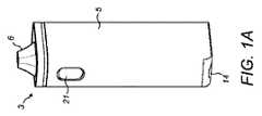
図1A〜図1Cは、本発明の一実施形態における電子タバコ3を示す。電子タバコ3は、刻み煙草を含む従来のタバコの代替品として使用することができる。電子タバコ3は、細長い本体5、マウスピース部6及びタバコのスティック(図示せず)を受け取るためのオーブン8を含む。オーブン8は、タバコのスティックを燃やすことなく加熱し、蒸気を生成することができる電気ヒーター10を含む。 1A-1C show the
蒸気チャネル12が設けられ、オーブン8とマウスピース部6との間に延びる。マウスピース部6は、使用者の口の人間工学に対応した先端形状になっている。電子タバコは、マウスピース部6及び蒸気チャネル12と流体連通している吸気口14を更に含み、それにより、マウスピース部6上で使用者が吸い込むことにより、空気が吸気口14に入って且つオーブン8及び蒸気チャネル12を通してマウスピース部6まで流れるようになる。使用者が電気ヒーター10による蒸気の生成を制御することができる作動ボタン21が設けられている。 A
電子タバコは、制御回路を含むプリント回路基板(PCB)4に電気的に接続された第1のバッテリー1及び第2のバッテリー2を含む。第1のバッテリー1は、PCB4及びPCB4に接続された制御回路に電力を供給するように構成される。第2のバッテリー2は、PCB4内の制御回路の制御下で電気ヒーター10に電力を供給するように構成される。一例では、第1のバッテリー1は、リチウムポリマーバッテリーとしても知られる、ソフトな袋を備えたLCO(リチウムコバルト酸化物)角柱バッテリーである。この例では、第1のバッテリー1は、寸法が約30×15×7mmであり、容量が200〜300mAhであり、完全に充電されたときに約3.7Vの動作電圧を提供する。一例では、第2のバッテリー2は、容量が1100mAhの円筒形の形状をしたLTO(チタン酸リチウム酸化物)バッテリーであり、完全に充電されたときに約2.4Vの動作電圧を提供する。第2のバッテリー2の容量は、第1のバッテリー1の容量よりも大幅に高く、なぜなら、第2のバッテリー2によって給電される電気ヒーター10は、第1のバッテリー1によって給電される制御回路よりも所要電力が大きいからである。 The electronic cigarette includes a first battery 1 and a
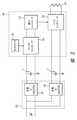
図2は、上述した電子タバコ3内の電気部品を示す概略回路図である。この回路図は、第1のバッテリー1及び第2のバッテリー2を含む。第1のバッテリー1は、制御システム16内のPCB4上のマイクロコントローラ18に電力を供給する。マイクロコントローラ18は、効果的に動作するためには、約3.3Vである第1の閾値を上回る電圧を有する電源によって給電される必要がある。第1のバッテリー1は、マイクロコントローラ18に適切な電力供給を供給することができるように特に選択され、及び第1のバッテリーは、完全に充電されたとき、第1の閾値を上回る約3.7Vの動作電圧を提供する。 FIG. 2 is a schematic circuit diagram showing the electric components in the above-mentioned
制御システム16は、圧力センサ20も含む。圧力センサ20は、電子タバコ3の蒸気チャネル12内の圧力を測定し、信号をマイクロコントローラ18に提供するように構成される。従って、使用者がマウスピース6上で吸い込むのに関連した圧力の低下を圧力センサ20が感知したとき、マイクロコントローラ18は、信号を提供して電気ヒーター10を作動させることができる。圧力センサ20の代替として、使用者がヒーター10を動作させるために押し下げることができる単純な作動押しボタン21が設けられ得る。 The
マイクロコントローラ18は、PCB4上の電力コントローラ22に接続される。電力コントローラ22は、バックジェネレータ24にパルス幅変調制御信号を提供するように構成され、バックジェネレータ24は、第2のバッテリー2と電気ヒーター10との間に配置され、電圧変換器として機能する。 The
第2のバッテリー2は、電気ヒーター10に電力を供給するように構成される。バックジェネレータ24は、第2のバッテリー2と電気ヒーター10との間に配置され、電圧増倍器として機能する。バックジェネレータ24は、約2.4Vである(上述した第1の閾値を下回る)、第2のバッテリーから出力された電圧を、電気ヒーター10の正常動作に必要とされる電圧に変換する。必要とされる正確な電圧は、選択された電気ヒーター10の特性に依存する。一実施形態では、バックジェネレータ24は、テキサス・インスツルメンツ社からのCSD95377回路に基づき得る。代わりに、同期している又は非同期の別個のシステムが設けられ得る。 The
第1及び第2のバッテリー1、2に対して充電システム26も設けられ、これらのバッテリーは、この実施形態では再充電可能である。電力供給ポートがUSBポート28の形態で設けられる。第1のバッテリー1に対して第1の充電集積回路(IC)31が設けられ、第2のバッテリー2に対して第2の充電IC32が設けられる。この例示的な実施形態では、第1及び第2の充電IC31、32は、テキサス・インスツルメンツ社からのbq24725A ICに基づいており、これは、異なる化学的性質を有するバッテリーをサポートすることができる。 Charging
使用時、USBポート28に電力ケーブルが接続され、第1及び第2のバッテリー1、2は、充電システム26によって充電される。完全に充電されたとき、第1のバッテリー1は、約3.7Vの電圧出力を提供し、これは、第1の閾値を上回り、従って制御システム16内のマイクロコントローラ18に給電するのに十分な大きさである。制御システム16は、第1のバッテリー1から適切な電力供給を受け取ると、アクティブになる。アクティブな制御システム16は、圧力センサ20によって適切な圧力低下が検出されると、ヒーター10を作動させる準備が整っている。圧力センサ20によって適切な圧力低下が検出されると、マイクロコントローラ18は、電力コントローラ22に信号を送り、電力コントローラ22は、バックジェネレータ24を介して、第2のバッテリー2から電気ヒーター10への電力の供給を制御することができる。バックジェネレータ24は、第2のバッテリー2から出力された約2.4Vである電圧を、電気ヒーター10によって必要とされるより大きい電圧に変換することができる。 During use, a power cable is connected to the
第2のバッテリー2が約2.4Vの出力電圧を提供することは、注目に値し、この電圧は、マイクロコントローラ18の動作に必要な第1の閾値を下回り、2.6Vの第2の閾値も下回る。第2のバッテリー2から出力された電圧を使用することによって制御システム16を作動させることは、不可能である。同様に、マイクロコントローラ18に信号を供給するために第2のバッテリー2からの電圧を変換することは、不可能であり、なぜなら、そのような変換は、やはり最小の動作電圧を必要とする制御システムを介して実施される必要があるからである。現在の構成は、マイクロコントローラ18の動作に必要とされる閾値を下回る電圧を有する電気ヒーター10のみに電力を供給するために第2のバッテリー2を使用することを可能にする。これは、多くの望ましい特性を有するものの、低電圧出力を提供することが多いLTOバッテリーを含めて、より幅広い種類のバッテリーと共に電子タバコ3を使用することを促進する。 It is noteworthy that the
図3は、本発明の代替的な実施形態における電子タバコ3内の構成要素の概略回路図である。この実施形態では、マイクロコントローラ18は、圧力センサ20及び作動ボタン21からの入力信号を受け取ることができる。従って、前述のように、マイクロコントローラ18は、作動ボタン21の押し下げ又は圧力センサ20による圧力低下の検出に基づいて電気ヒーター10の動作を制御することができる。この例示的な実施形態では、マイクロコントローラ18は、バックジェネレータ24に接続された統合電力コントローラを含む。 FIG. 3 is a schematic circuit diagram of the components in the
制御システム16は、フィードバック制御のために使用することができるセンサ25も含む。センサの例としては、温度センサ、コイル抵抗センサ及び気化可能材料内の水分含量を決定するための水分センサが挙げられる。1つ又は複数のセンサ25からの測定値は、マイクロコントローラ18内の統合PIDコントローラに提供され得る。1つ又は複数のセンサ25からの信号を使用して、第2のバッテリー2により電気ヒーター10に供給される電力を制御することができる。 The
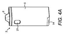
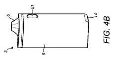
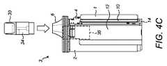
図4A〜図4Cは、本発明の別の実施形態における電子タバコ3を示す。この例示的な実施形態では、気化可能な媒体は、タバコのスティックではなく、液体である。カプセル30は、気化可能な液体を貯蔵するためのリザーバ34を含む。カートリッジ30は、統合電気ヒーター(図示せず)を含み、このヒーターは、使用者が吸入するための気化可能な液体を気化させるための電力を供給され得る。使用時、カートリッジ30は、電子タバコ3の上端にある収容部36内に収容される。気化可能な液体は、目に見える蒸気を生成することができるプロピレングリコール又はグリセリンであり得る。気化可能な液体は、ニコチン及び香料などの他の物質を更に含み得る。カートリッジの代替として、リザーバは、詰め替え可能な「オープンタンク」リザーバとして構成され得る。 4A-4C show the
液体ベースの電子タバコでは、電気ヒーターは、低電圧であっても動作することができる低抵抗コイルとして提供され得る。例えば、おそらく1Ω以下の非常に低い抵抗率を有するチタンコイルが使用され得る。従って、これらの実施形態では、バックコンバータを使用する必要がないことがあり得る。しかしながら、これらの実施形態では、制御システムが依然として必要である。 In liquid-based e-cigarettes, the electric heater can be provided as a low resistance coil that can operate even at low voltages. For example, a titanium coil with a very low resistivity of perhaps 1Ω or less may be used. Therefore, in these embodiments, it may not be necessary to use a back converter. However, in these embodiments, a control system is still required.
Claims (13)
Translated fromJapaneseエアロゾル形成基質を加熱して、吸入可能なエアロゾルを生成するための電気ヒーターと、
前記電気ヒーターへの電力の供給を制御するように構成された制御回路と、
第1のバッテリーであって、完全に充電されたとき、第1の閾値を上回る第1の動作電圧を有し、前記制御回路に電気的に接続され、且つ使用時に前記制御回路に電力を供給するように構成される第1のバッテリーと、
第2のバッテリーであって、完全に充電されたとき、前記第1の閾値を下回る第2の動作電圧を有し、前記電気ヒーターに電気的に接続され、且つ使用時に前記電気ヒーターに電力を供給するように構成される第2のバッテリーと
を含む電子タバコ。It ’s an electronic cigarette,
With an electric heater to heat the aerosol-forming substrate to produce an inhalable aerosol,
A control circuit configured to control the supply of electric power to the electric heater, and
A first battery that, when fully charged, has a first operating voltage that exceeds the first threshold, is electrically connected to the control circuit, and powers the control circuit when in use. With a first battery configured to
A second battery that, when fully charged, has a second operating voltage below the first threshold, is electrically connected to the electric heater, and powers the electric heater when in use. An electronic cigarette including a second battery configured to supply.
前記第1のバッテリーから前記制御回路に電力を供給するステップであって、前記第1のバッテリーは、完全に充電されたとき、第1の閾値を上回る第1の動作電圧を有する、ステップと、
前記第2のバッテリーから前記電気ヒーターに電力を供給するステップであって、前記第2のバッテリーは、完全に充電されたとき、前記第1の閾値を下回る第2の動作電圧を有する、ステップと
を含む、方法。A method of operating an e-cigarette, wherein the e-cigarette is configured to heat an aerosol-forming substrate to produce an electric heater for producing an inhalable aerosol and to control the supply of electric power to the electric heater. The method comprises a control circuit, a first battery, and a second battery.
A step of supplying power from the first battery to the control circuit, wherein the first battery has a first operating voltage that exceeds a first threshold when fully charged.
A step of supplying power from the second battery to the electric heater, wherein the second battery has a second operating voltage below the first threshold when fully charged. Including the method.
Applications Claiming Priority (3)
| Application Number | Priority Date | Filing Date | Title |
|---|---|---|---|
| EP18196169.9 | 2018-09-24 | ||
| EP18196169 | 2018-09-24 | ||
| PCT/EP2019/074330WO2020064347A1 (en) | 2018-09-24 | 2019-09-12 | Dual battery electronic cigarette |
Publications (1)
| Publication Number | Publication Date |
|---|---|
| JP2022502022Atrue JP2022502022A (en) | 2022-01-11 |
Family
ID=63683012
Family Applications (1)
| Application Number | Title | Priority Date | Filing Date |
|---|---|---|---|
| JP2021516384APendingJP2022502022A (en) | 2018-09-24 | 2019-09-12 | Dual battery electronic cigarette |
Country Status (6)
| Country | Link |
|---|---|
| US (1) | US20210169150A1 (en) |
| EP (1) | EP3855951A1 (en) |
| JP (1) | JP2022502022A (en) |
| CN (1) | CN112752521A (en) |
| EA (1) | EA202190571A1 (en) |
| WO (1) | WO2020064347A1 (en) |
Cited By (1)
| Publication number | Priority date | Publication date | Assignee | Title |
|---|---|---|---|---|
| WO2025028948A1 (en)* | 2023-08-01 | 2025-02-06 | 주식회사 케이티앤지 | Aerosol-generating device and operation method thereof |
Families Citing this family (11)
| Publication number | Priority date | Publication date | Assignee | Title |
|---|---|---|---|---|
| CN111869930A (en)* | 2020-06-30 | 2020-11-03 | 上海烟草集团有限责任公司 | Power supply device and aerial fog generating device |
| JP6882585B1 (en) | 2020-09-07 | 2021-06-02 | 日本たばこ産業株式会社 | Controller for aspirator |
| KR102609589B1 (en)* | 2020-09-11 | 2023-12-04 | 주식회사 케이티앤지 | System-in-package and aerosol senerating apparatus comprising the same |
| WO2022130492A1 (en)* | 2020-12-15 | 2022-06-23 | 日本たばこ産業株式会社 | Inhalation device, control method, and program |
| KR102621761B1 (en)* | 2021-04-01 | 2024-01-05 | 주식회사 케이티앤지 | Aerosol generating apparatus determining whether aerosol generating article is over-humid state |
| EP4338610A4 (en)* | 2021-05-10 | 2025-04-02 | Japan Tobacco Inc. | CIRCUIT UNIT FOR AEROSOL GENERATING DEVICE, AND AEROSOL GENERATING DEVICE |
| KR102600665B1 (en)* | 2021-07-22 | 2023-11-09 | 주식회사 케이티앤지 | Aerosol generating apparatus for sensing aerosol generating article and operation method thereof |
| DE102021126845B3 (en)* | 2021-10-15 | 2023-01-12 | Dicodes Gmbh | Energy supply device, e-cigarette and method for generating electrical power |
| JP2025525675A (en)* | 2022-07-29 | 2025-08-05 | フィリップ・モーリス・プロダクツ・ソシエテ・アノニム | Aerosol Generating Device with Multiple Power Supplies |
| CN115399510A (en)* | 2022-09-28 | 2022-11-29 | 爱奇迹(深圳)创新科技有限公司 | Electronic atomizer |
| EP4563018A1 (en)* | 2023-11-30 | 2025-06-04 | JT International SA | Aerosol generating device |
Citations (3)
| Publication number | Priority date | Publication date | Assignee | Title |
|---|---|---|---|---|
| JP2014203108A (en)* | 2013-04-01 | 2014-10-27 | 日本電気硝子株式会社 | Control apparatus, program, and plate glass manufacturing apparatus |
| CN204070568U (en)* | 2014-08-14 | 2015-01-07 | 深圳市合元科技有限公司 | The electronic cigarette of dual power supply |
| US20170215477A1 (en)* | 2016-02-01 | 2017-08-03 | Tony Reevell | Aerosol-generating device having multiple power supplies |
Family Cites Families (12)
| Publication number | Priority date | Publication date | Assignee | Title |
|---|---|---|---|---|
| EP2701268A1 (en)* | 2012-08-24 | 2014-02-26 | Philip Morris Products S.A. | Portable electronic system including charging device and method of charging a secondary battery |
| AU2012388105B2 (en)* | 2012-08-24 | 2017-01-12 | Huizhou Kimree Technology Co., Ltd. | Electronic cigarette apparatus |
| US20150305409A1 (en)* | 2013-11-12 | 2015-10-29 | VMR Products, LLC | Vaporizer |
| US10039321B2 (en)* | 2013-11-12 | 2018-08-07 | Vmr Products Llc | Vaporizer |
| GB2524736B (en)* | 2014-03-31 | 2021-02-24 | Nicoventures Holdings Ltd | Re-charging pack for an e-cigarette |
| CN104116138B (en)* | 2014-06-24 | 2017-10-10 | 深圳麦克韦尔股份有限公司 | Electronic cigarette and its control method |
| CN104489935B (en)* | 2015-01-14 | 2017-08-15 | 东莞市泽迈五金科技有限公司 | Electronic cigarette |
| CN204706897U (en)* | 2015-04-10 | 2015-10-14 | 华健 | A kind of new-type circuit of powering to electronic cigarette |
| GB201515087D0 (en)* | 2015-08-25 | 2015-10-07 | Nicoventures Holdings Ltd | Electronic vapour provision system |
| EP3410876B1 (en)* | 2016-02-01 | 2020-04-01 | Philip Morris Products S.a.s. | Aerosol-generating device having multiple power supplies |
| US10517326B2 (en)* | 2017-01-27 | 2019-12-31 | Rai Strategic Holdings, Inc. | Secondary battery for an aerosol delivery device |
| CN207855034U (en)* | 2017-12-26 | 2018-09-14 | 深圳市舜宝科技有限公司 | Electronic cigarette packet and electronic cigarette system |
- 2019
- 2019-09-12JPJP2021516384Apatent/JP2022502022A/enactivePending
- 2019-09-12EAEA202190571Apatent/EA202190571A1/enunknown
- 2019-09-12USUS17/270,299patent/US20210169150A1/ennot_activeAbandoned
- 2019-09-12EPEP19765501.2Apatent/EP3855951A1/enactivePending
- 2019-09-12CNCN201980061767.6Apatent/CN112752521A/enactivePending
- 2019-09-12WOPCT/EP2019/074330patent/WO2020064347A1/ennot_activeCeased
Patent Citations (3)
| Publication number | Priority date | Publication date | Assignee | Title |
|---|---|---|---|---|
| JP2014203108A (en)* | 2013-04-01 | 2014-10-27 | 日本電気硝子株式会社 | Control apparatus, program, and plate glass manufacturing apparatus |
| CN204070568U (en)* | 2014-08-14 | 2015-01-07 | 深圳市合元科技有限公司 | The electronic cigarette of dual power supply |
| US20170215477A1 (en)* | 2016-02-01 | 2017-08-03 | Tony Reevell | Aerosol-generating device having multiple power supplies |
Cited By (1)
| Publication number | Priority date | Publication date | Assignee | Title |
|---|---|---|---|---|
| WO2025028948A1 (en)* | 2023-08-01 | 2025-02-06 | 주식회사 케이티앤지 | Aerosol-generating device and operation method thereof |
Also Published As
| Publication number | Publication date |
|---|---|
| WO2020064347A1 (en) | 2020-04-02 |
| EA202190571A1 (en) | 2021-07-02 |
| CN112752521A (en) | 2021-05-04 |
| EP3855951A1 (en) | 2021-08-04 |
| US20210169150A1 (en) | 2021-06-10 |
Similar Documents
| Publication | Publication Date | Title |
|---|---|---|
| JP2022502022A (en) | Dual battery electronic cigarette | |
| KR102717481B1 (en) | Intelligent charger for aerosol delivery devices | |
| JP7562726B2 (en) | Aerosol generating system with overheat protection | |
| RU2744675C2 (en) | Boost converter for aerosol delivery device | |
| RU2711461C2 (en) | Supplying power to aerosol delivery device | |
| RU2728771C2 (en) | Aerosol delivery device charging device | |
| RU2745104C2 (en) | Converter of radio frequency into direct current for an aerosol delivery device | |
| RU2753553C2 (en) | Rechargeable lithium-ion battery for aerosol delivery device | |
| EP3410876B1 (en) | Aerosol-generating device having multiple power supplies | |
| EP3547858B1 (en) | Rechargeable lithium-ion capacitor for an aerosol delivery device | |
| EA040566B1 (en) | ELECTRONIC CIGARETTE WITH TWO BATTERIES | |
| RU2775726C2 (en) | Smart battery charger for aerosol delivery device | |
| HK40044493A (en) | Aerosol-generating system with overheating prevention | |
| HK40024518A (en) | Aerosol-generating system with overheating prevention | |
| HK40024518B (en) | Aerosol-generating system with overheating prevention |
Legal Events
| Date | Code | Title | Description |
|---|---|---|---|
| A621 | Written request for application examination | Free format text:JAPANESE INTERMEDIATE CODE: A621 Effective date:20220804 | |
| A131 | Notification of reasons for refusal | Free format text:JAPANESE INTERMEDIATE CODE: A131 Effective date:20230929 | |
| A977 | Report on retrieval | Free format text:JAPANESE INTERMEDIATE CODE: A971007 Effective date:20230929 | |
| A521 | Request for written amendment filed | Free format text:JAPANESE INTERMEDIATE CODE: A523 Effective date:20231228 | |
| A02 | Decision of refusal | Free format text:JAPANESE INTERMEDIATE CODE: A02 Effective date:20240314 | |
| A521 | Request for written amendment filed | Free format text:JAPANESE INTERMEDIATE CODE: A523 Effective date:20240716 | |
| A911 | Transfer to examiner for re-examination before appeal (zenchi) | Free format text:JAPANESE INTERMEDIATE CODE: A911 Effective date:20240724 | |
| A912 | Re-examination (zenchi) completed and case transferred to appeal board | Free format text:JAPANESE INTERMEDIATE CODE: A912 Effective date:20240823 |