Movatterモバイル変換


[0]ホーム

URL:


JP2022184499A - acoustic device - Google Patents

acoustic device
Download PDF

Info

Publication number
JP2022184499A
JP2022184499AJP2021092395AJP2021092395AJP2022184499AJP 2022184499 AJP2022184499 AJP 2022184499AJP 2021092395 AJP2021092395 AJP 2021092395AJP 2021092395 AJP2021092395 AJP 2021092395AJP 2022184499 AJP2022184499 AJP 2022184499A
Authority
JP
Japan
Prior art keywords
pair
acoustic device
support member
support members
main surface
Prior art date
Legal status (The legal status is an assumption and is not a legal conclusion. Google has not performed a legal analysis and makes no representation as to the accuracy of the status listed.)
Granted
Application number
JP2021092395A
Other languages
Japanese (ja)
Other versions
JP7663415B2 (en
Inventor
敦 江澤
Atsushi Ezawa
慧大 永井
Keita Nagai
Current Assignee (The listed assignees may be inaccurate. Google has not performed a legal analysis and makes no representation or warranty as to the accuracy of the list.)
TDK Corp
Original Assignee
TDK Corp
Priority date (The priority date is an assumption and is not a legal conclusion. Google has not performed a legal analysis and makes no representation as to the accuracy of the date listed.)
Filing date
Publication date
Application filed by TDK CorpfiledCriticalTDK Corp
Priority to JP2021092395ApriorityCriticalpatent/JP7663415B2/en
Publication of JP2022184499ApublicationCriticalpatent/JP2022184499A/en
Application grantedgrantedCritical
Publication of JP7663415B2publicationCriticalpatent/JP7663415B2/en
Activelegal-statusCriticalCurrent
Anticipated expirationlegal-statusCritical

Links

Images

Landscapes

Abstract

To provide an acoustic device capable of improving sound pressure characteristics in a wide frequency band.SOLUTION: An acoustic device 1 arranged on a substrate B includes a vibration unit 2 and a plurality of support members 4a, 4b. The vibration unit 2 has a piezoelectric element 10 and a diaphragm 30 to which the piezoelectric element 10 is joined, and vibrates by expansion and contraction of the piezoelectric element 10. The plurality of support members 4a, 4b supports the vibration unit 2 to the substrate B and vibrates by the vibration of the vibration unit 2. The diaphragm 30 includes a first area 31 where the piezoelectric element 10 is joined and a pair of second areas 32, 33 located on both sides of the first area 31. The support member 4a is arranged in a corresponding second area 32 of the pair of second areas 32, 33. The plurality of support members 4b is arranged in a corresponding second area 33 of the pair of second areas 32, 33. The resonance frequency of the vibration unit 2 is different from the resonance frequencies of the plurality of support members 4a, 4b.SELECTED DRAWING: Figure 1

Description

Translated fromJapanese

本発明は、音響デバイスに関する。 The present invention relates to acoustic devices.

知られている音響デバイスは、圧電素子と、圧電素子が接合されている振動板と、を備えている。(たとえば、特許文献1参照)。音響デバイスは、たとえば、基材に配置される。振動板は、圧電素子の伸縮によって振動する。 A known acoustic device comprises a piezoelectric element and a diaphragm to which the piezoelectric element is bonded. (See Patent Document 1, for example). An acoustic device, for example, is placed on the substrate. The diaphragm vibrates due to expansion and contraction of the piezoelectric element.

特開平4-70100号公報JP-A-4-70100

本発明の一つの態様は、幅広い周波数帯域で音圧特性を向上する音響デバイスを提供することを目的とする。 An object of one aspect of the present invention is to provide an acoustic device that improves sound pressure characteristics in a wide frequency band.

本発明の一つの態様に係る音響デバイスは、基材に配置される音響デバイスであって、振動ユニットと、複数の支持部材とを備えている。振動ユニットは、圧電素子と、圧電素子が接合されている振動板とを有しており、圧電素子の伸縮によって振動する。複数の支持部材は、振動ユニットを基材に支持し、振動ユニットの振動によって振動する。振動板は、圧電素子が接合されている第一領域と、第一領域の両側に位置している一対の第二領域とを含む。複数の支持部材は、一対の第二領域のうち対応する第二領域にそれぞれ配置されている。振動ユニットの共振周波数は、複数の支持部材の共振周波数と異なる。 An acoustic device according to one aspect of the present invention is an acoustic device arranged on a substrate, and includes a vibrating unit and a plurality of support members. The vibration unit has a piezoelectric element and a vibration plate to which the piezoelectric element is bonded, and vibrates due to expansion and contraction of the piezoelectric element. The plurality of supporting members support the vibrating unit on the base material and vibrate due to the vibration of the vibrating unit. The diaphragm includes a first region to which the piezoelectric element is bonded and a pair of second regions located on opposite sides of the first region. The plurality of support members are arranged in corresponding second regions of the pair of second regions. The resonant frequency of the vibrating unit is different than the resonant frequencies of the plurality of support members.

上記一つの態様では、振動ユニットの共振周波数と、複数の支持部材の共振周波数とが、異なっている。したがって、振動ユニットの共振周波数と、複数の支持部材の共振周波数とにおいて、音圧が増大する。この結果、上記一つの態様は、幅広い周波数帯域で、音圧特性を向上する。 In the one aspect described above, the resonance frequency of the vibrating unit and the resonance frequencies of the plurality of support members are different. Therefore, the sound pressure increases at the resonance frequency of the vibrating unit and the resonance frequencies of the plurality of support members. As a result, the one aspect described above improves sound pressure characteristics in a wide frequency band.

上記一つの態様では、各支持部材は、振動板に連結されている第一部分と、基材に連結される第二部分と、第一部分と第二部分との間に位置している第三部分とを有していてもよい。第三部分では、断面積が部分的に小さくてもよい。
各支持部材が、断面積が部分的に小さい第三部分を有している構成では、各支持部材の共振周波数は、第三部分の形状、すなわち断面積に応じて変化する。したがって、本構成では、各支持部材の共振周波数が所望の周波数に容易かつ確実に調整され得る。
In the above aspect, each support member has a first portion connected to the diaphragm, a second portion connected to the base, and a third portion located between the first portion and the second portion. and may have The cross-sectional area may be partially reduced in the third portion.
In configurations in which each support member has a third portion with a partially reduced cross-sectional area, the resonant frequency of each support member varies depending on the shape, ie cross-sectional area, of the third portion. Therefore, with this configuration, the resonance frequency of each support member can be easily and reliably adjusted to a desired frequency.

上記一つの態様では、各支持部材は、第四部分を有していてもよい。第四部分は、第一部分と第二部分との間に位置していると共に断面積が部分的に小さくてもよい。
各支持部材が、断面積が部分的に小さい第四部分を有している構成では、各支持部材の共振周波数は、第三部分の形状のほか、第四部分の形状、すなわち断面積に応じても変化する。したがって、本構成では、各支持部材の共振周波数が所望の周波数により一層容易かつ確実に調整され得る。
In one aspect, each support member may have a fourth portion. The fourth portion may be located between the first portion and the second portion and may have a partially reduced cross-sectional area.
In configurations where each support member has a fourth portion with a partially smaller cross-sectional area, the resonant frequency of each support member depends on the shape of the third portion as well as the shape, i.e. cross-sectional area, of the fourth portion. changes even Therefore, with this configuration, the resonance frequency of each support member can be adjusted to a desired frequency more easily and reliably.

上記一つの態様では、振動板は、各支持部材が連結されている主面を含んでいてもよい。各支持部材は、主面を含む仮想平面と交差する方向に延在していてもよい。
各支持部材が主面を含む仮想平面と交差する方向に延在している構成は、主面と直交する方向から見たときの音響デバイスのサイズを低減し得る。
In one aspect, the diaphragm may include a main surface to which the support members are connected. Each support member may extend in a direction intersecting a virtual plane containing the main surface.
A configuration in which each support member extends in a direction that intersects an imaginary plane containing the main surface can reduce the size of the acoustic device when viewed from a direction perpendicular to the main surface.

上記一つの態様では、振動板は、各支持部材が連結されている主面を含んでいてもよい。各支持部材は、主面を含む仮想平面と平行な方向に延在していてもよい。
各支持部材が主面を含む仮想平面と平行な方向に延在している構成は、主面と直交する方向での、音響デバイスのサイズを低減し得る。
In one aspect, the diaphragm may include a main surface to which the support members are connected. Each support member may extend in a direction parallel to an imaginary plane containing the main surface.
A configuration in which each support member extends in a direction parallel to an imaginary plane containing the major surface can reduce the size of the acoustic device in a direction perpendicular to the major surface.

上記一つの態様では、振動板及び各支持部材は、金属からなってもよい。 In the above aspect, the diaphragm and each support member may be made of metal.

本発明の一つの態様は、幅広い周波数帯域で音圧特性を向上する音響デバイスを提供する。 One aspect of the present invention provides an acoustic device that improves sound pressure characteristics over a wide frequency band.

図1は、第一実施形態に係る音響デバイスの断面構成を示す図である。FIG. 1 is a diagram showing a cross-sectional configuration of an acoustic device according to the first embodiment.図2は、本実施形態に係る圧電素子の断面構成を示す図である。FIG. 2 is a diagram showing the cross-sectional configuration of the piezoelectric element according to this embodiment.図3は、第一実施形態に係る音響デバイスの周波数特性を示す図である。FIG. 3 is a diagram showing frequency characteristics of the acoustic device according to the first embodiment.図4は、第二実施形態に係る音響デバイスの断面構成を示す図である。FIG. 4 is a diagram showing a cross-sectional configuration of an acoustic device according to the second embodiment.図5は、第二実施形態に係る音響デバイスの周波数特性を示す図である。FIG. 5 is a diagram showing frequency characteristics of the acoustic device according to the second embodiment.図6は、第三実施形態に係る音響デバイスの断面構成を示す図である。FIG. 6 is a diagram showing a cross-sectional configuration of an acoustic device according to the third embodiment.図7は、第四実施形態に係る音響デバイスの断面構成を示す図である。FIG. 7 is a diagram showing a cross-sectional configuration of an acoustic device according to the fourth embodiment.図8は、変形例に係る各支持部材を示す拡大図である。FIG. 8 is an enlarged view showing each support member according to a modification.

以下では、図面を参照しながら本発明に係る実施形態について説明する。図面の説明において、同一又は相当する要素には同一の符号を付し、重複する説明を適宜省略する。 Embodiments according to the present invention will be described below with reference to the drawings. In the description of the drawings, the same or corresponding elements are denoted by the same reference numerals, and duplicate descriptions are omitted as appropriate.

(第一実施形態)
図1~図3を参照して、第一実施形態に係る音響デバイス1の構成を説明する。図1は、第一実施形態に係る音響デバイス1の断面構成を示す図である。図2は、本実施形態に係る圧電素子10の断面構成を示す図である。図3は、第一実施形態に係る音響デバイス1の周波数特性を示す図である。音響デバイス1の周波数特性とは、音響デバイス1における、周波数と振幅の関係を意味する。
(First embodiment)
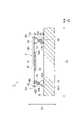
The configuration of an acoustic device 1 according to the first embodiment will be described with reference to FIGS. 1 to 3. FIG. FIG. 1 is a diagram showing a cross-sectional configuration of an acoustic device 1 according to the first embodiment. FIG. 2 is a diagram showing a cross-sectional configuration of thepiezoelectric element 10 according to this embodiment. FIG. 3 is a diagram showing frequency characteristics of the acoustic device 1 according to the first embodiment. The frequency characteristic of the acoustic device 1 means the relationship between frequency and amplitude in the acoustic device 1 .

音響デバイス1は、図1に示されるように、基材Bに配置される。音響デバイス1は、基材Bに対して振動することで、音圧を出力する。音響デバイス1は、たとえば、スピーカ又はブザーに用いられる。音響デバイス1は、振動ユニット2と、振動ユニット2を基材Bに支持する複数の支持部材4a,4bと、を備えている。本実施形態では、音響デバイス1は、一対の支持部材4a,4bを備えている。 Acoustic device 1 is placed on substrate B as shown in FIG. The acoustic device 1 vibrates with respect to the base material B to output sound pressure. Acoustic device 1 is used, for example, as a speaker or a buzzer. The acoustic device 1 includes avibrating unit 2 and a plurality ofsupport members 4a and 4b that support the vibratingunit 2 on the base material B. As shown in FIG. In this embodiment, the acoustic device 1 includes a pair ofsupport members 4a and 4b.

振動ユニット2は、圧電素子10と、圧電素子10が接合されている振動板30と、を有している。圧電素子10は、たとえば、バイモルフ型の圧電素子である。圧電素子10は、図2に示されるように、圧電素体11と、複数の外部電極13,14,15と、を有している。本実施形態では、圧電素子10は、三つの外部電極13,14,15を有している。 Thevibration unit 2 has apiezoelectric element 10 and avibration plate 30 to which thepiezoelectric element 10 is bonded. Thepiezoelectric element 10 is, for example, a bimorph piezoelectric element. Thepiezoelectric element 10 has apiezoelectric body 11 and a plurality ofexternal electrodes 13, 14, 15, as shown in FIG. In this embodiment, thepiezoelectric element 10 has threeexternal electrodes 13 , 14 , 15 .

圧電素体11は、直方体形状を呈している。直方体形状には、たとえば、角部及び稜線部が面取りされている直方体の形状、及び、角部及び稜線部が丸められている直方体の形状が含まれる。圧電素体11は、互いに対向している一対の主面11a,11bと、一対の主面11a,11bを互いに接続している四つの側面11cと、を有している。 Thepiezoelectric element 11 has a rectangular parallelepiped shape. The rectangular parallelepiped shape includes, for example, a rectangular parallelepiped shape with chamfered corners and edges, and a rectangular parallelepiped shape with rounded corners and edges. Thepiezoelectric body 11 has a pair ofmain surfaces 11a and 11b facing each other and fourside surfaces 11c connecting the pair ofmain surfaces 11a and 11b to each other.

各主面11a,11bは、一対の長辺と一対の短辺とを有する長方形状を呈している。主面11aの長辺方向での圧電素体11の長さは、たとえば、10mm以上70mm以下である。主面11aの短辺方向での圧電素体11の長さは、たとえば、10mm以上50mm以下である。一対の主面11a,11bの対向方向での圧電素体11の長さは、たとえば、0.2mm以上1.0mm以下である。 Eachprincipal surface 11a, 11b has a rectangular shape with a pair of long sides and a pair of short sides. The length of thepiezoelectric body 11 in the long side direction of themain surface 11a is, for example, 10 mm or more and 70 mm or less. The length of thepiezoelectric body 11 in the short side direction of themain surface 11a is, for example, 10 mm or more and 50 mm or less. The length of thepiezoelectric body 11 in the direction in which the pair ofmain surfaces 11a and 11b face each other is, for example, 0.2 mm or more and 1.0 mm or less.

圧電素体11は、積層された複数の圧電体層12a,12b,12c,12dを含んでいる。複数の圧電体層12a,12b,12c,12dは、この順に積層されている。複数の圧電体層12a,12b,12c,12dの積層方向は、一対の主面11a,11bの対向方向と一致している。以下では、複数の圧電体層12a,12b,12c,12dの積層方向を、積層方向と称する。圧電体層12aは、主面11aを有している。圧電体層12dは、主面11bを有している。圧電体層12b,12cは、圧電体層12aと圧電体層12dとの間に位置している。本実施形態では、各圧電体層12a,12b,12c,12dの厚みは同等である。同等には、製造誤差の範囲が含まれている。 Thepiezoelectric body 11 includes a plurality of stackedpiezoelectric layers 12a, 12b, 12c, and 12d. A plurality ofpiezoelectric layers 12a, 12b, 12c, and 12d are laminated in this order. The stacking direction of the plurality ofpiezoelectric layers 12a, 12b, 12c, 12d coincides with the facing direction of the pair ofmain surfaces 11a, 11b. Hereinafter, the stacking direction of the plurality ofpiezoelectric layers 12a, 12b, 12c, and 12d will be referred to as the stacking direction. Thepiezoelectric layer 12a has amain surface 11a. Thepiezoelectric layer 12d has amain surface 11b. Thepiezoelectric layers 12b and 12c are located between thepiezoelectric layers 12a and 12d. In this embodiment, thepiezoelectric layers 12a, 12b, 12c, and 12d have the same thickness. Equivalence includes a margin of manufacturing error.

各圧電体層12a,12b,12c,12dは、圧電材料からなる。本実施形態では、各圧電体層12a,12b,12c,12dは、圧電セラミック材料からなる。圧電セラミック材料には、たとえば、PZT[Pb(Zr、Ti)O]、PT(PbTiO)、PLZT[(Pb,La)(Zr、Ti)O]、又はチタン酸バリウム(BaTiO)が用いられる。各圧電体層12a,12b,12c,12dは、たとえば、上述した圧電セラミック材料を含むセラミックグリーンシートの焼結体から構成される。実際の圧電素体11では、各圧電体層12a,12b,12c,12dは、各圧電体層12a,12b,12c,12dの間の境界が認識できない程度に一体化されている。Eachpiezoelectric layer 12a, 12b, 12c, 12d is made of a piezoelectric material. In this embodiment, eachpiezoelectric layer 12a, 12b, 12c, 12d is made of a piezoelectric ceramic material. Piezoelectric ceramic materials include, for example, PZT[Pb(Zr,Ti)O3 ], PT(PbTiO3 ), PLZT[(Pb,La)(Zr,Ti)O3 ], or barium titanate (BaTiO3 ). is used. Each of thepiezoelectric layers 12a, 12b, 12c, and 12d is composed of, for example, a sintered ceramic green sheet containing the piezoelectric ceramic material described above. In the actualpiezoelectric body 11, thepiezoelectric layers 12a, 12b, 12c and 12d are integrated to such an extent that the boundaries between thepiezoelectric layers 12a, 12b, 12c and 12d cannot be recognized.

圧電素子10において、各外部電極13,14,15は、主面11a上に配置されている。外部電極13,14,15は、主面11aの一方の短辺側において、外部電極13、外部電極14、外部電極15の順で当該一方の短辺に沿って並んでいる。外部電極13と外部電極14とは、主面11aの短辺方向で隣り合っている。外部電極14と外部電極15とは、主面11aの短辺方向で隣り合っている。主面11aの短辺方向において、外部電極14と外部電極15との間の距離は、外部電極13と外部電極14との間の距離よりも長い。各外部電極13,14,15は、積層方向から見て、主面11aの全ての縁から離間している。 In thepiezoelectric element 10, eachexternal electrode 13, 14, 15 is arranged on themain surface 11a. Theexternal electrodes 13 , 14 , 15 are arranged along one short side of themain surface 11 a in the order of theexternal electrode 13 , theexternal electrode 14 , and theexternal electrode 15 . Theexternal electrodes 13 and 14 are adjacent to each other in the short side direction of themain surface 11a. Theexternal electrodes 14 and 15 are adjacent to each other in the short side direction of themain surface 11a. The distance between theexternal electrodes 14 and 15 is longer than the distance between theexternal electrodes 13 and 14 in the short side direction of themain surface 11a. Each of theexternal electrodes 13, 14, 15 is separated from all edges of themain surface 11a when viewed in the stacking direction.

各外部電極13,14は、積層方向から見て、長方形状を呈している。本実施形態では、長方形状の各角が丸められている。外部電極15は、積層方向から見て、正方形状を呈している。正方形状には、たとえば、各角が面取りされている形状、及び、各角が丸められている形状が含まれる。本実施形態では、正方形状の各角が丸められている。各外部電極13,14,15は、導電性材料からなる。導電性材料には、たとえば、Ag、Pd、Pt、又はAg-Pd合金が用いられる。各外部電極13,14,15は、たとえば、上記導電性材料を含む導電性ペーストの焼結体として構成されている。 Each of theexternal electrodes 13 and 14 has a rectangular shape when viewed from the stacking direction. In this embodiment, each corner of the rectangular shape is rounded. Theexternal electrodes 15 have a square shape when viewed from the stacking direction. The square shape includes, for example, a shape with chamfered corners and a shape with rounded corners. In this embodiment, each corner of the square is rounded. Eachexternal electrode 13, 14, 15 is made of a conductive material. Ag, Pd, Pt, or Ag--Pd alloys, for example, are used for the conductive material. Each of theexternal electrodes 13, 14, 15 is configured as, for example, a sintered body of a conductive paste containing the conductive material.

圧電素子10は、圧電素体11内に配置されている複数の内部電極16,17,18を備えている。各内部電極16,17,18は、導電性材料からなる。導電性材料には、たとえば、Ag、Pd、Pt、又はAg-Pd合金が用いられる。各内部電極16,17,18は、たとえば、上記導電性材料を含む導電性ペーストの焼結体として構成されている。本実施形態では、各内部電極16,17,18の外形形状は、長方形状を呈している。 Thepiezoelectric element 10 has a plurality ofinternal electrodes 16 , 17 , 18 arranged inside thepiezoelectric body 11 . Eachinternal electrode 16, 17, 18 is made of a conductive material. Ag, Pd, Pt, or Ag--Pd alloys, for example, are used for the conductive material. Each of theinternal electrodes 16, 17, 18 is configured as, for example, a sintered body of a conductive paste containing the conductive material. In this embodiment, the outer shape of eachinternal electrode 16, 17, 18 is rectangular.

各内部電極16,17,18は、この順に積層されている。すなわち、各内部電極16,17,18は、積層方向において、異なる層に配置されている。内部電極16,17,18は、互いに積層方向に間隔を有して対向している。各内部電極16,17,18は、圧電素体11の表面には露出していない。すなわち、各内部電極16,17,18は、各側面11cには露出していない。各内部電極16,17,18は、積層方向から見て、主面11a,11bの全ての縁から離間している。 Eachinternal electrode 16, 17, 18 is laminated in this order. That is, theinternal electrodes 16, 17, 18 are arranged in different layers in the stacking direction. Theinternal electrodes 16, 17, 18 face each other with a gap in the lamination direction. Eachinternal electrode 16 , 17 , 18 is not exposed on the surface of thepiezoelectric body 11 . That is, theinternal electrodes 16, 17, 18 are not exposed on the side surfaces 11c. Each of theinternal electrodes 16, 17, 18 is separated from all the edges of themain surfaces 11a, 11b when viewed in the stacking direction.

内部電極16は、圧電体層12aと圧電体層12bとの間に位置している。内部電極17は、圧電体層12bと圧電体層12cとの間に位置している。内部電極18は、圧電体層12cと圧電体層12dとの間に位置している。 Theinternal electrode 16 is positioned between thepiezoelectric layers 12a and 12b. Theinternal electrode 17 is positioned between thepiezoelectric layer 12b and thepiezoelectric layer 12c. Theinternal electrode 18 is positioned between thepiezoelectric layer 12c and thepiezoelectric layer 12d.

外部電極13は、内部電極16と複数の接続導体21とに複数のビア導体24を通して電気的に接続されている。複数の接続導体21は、それぞれ、内部電極17,18と同じ層に位置している。具体的には、各接続導体21は、各内部電極17,18に形成された開口内に位置している。各開口は、積層方向から見て、外部電極13に対応する位置に形成されている。すなわち、各接続導体21は、積層方向から見て、各内部電極17,18に囲まれている。各接続導体21は、各内部電極17,18から離間している。 Theexternal electrodes 13 are electrically connected to theinternal electrodes 16 and the plurality ofconnection conductors 21 through a plurality of viaconductors 24 . The plurality ofconnection conductors 21 are located on the same layer as theinternal electrodes 17 and 18, respectively. Specifically, eachconnection conductor 21 is positioned within an opening formed in eachinternal electrode 17 , 18 . Each opening is formed at a position corresponding to theexternal electrode 13 when viewed in the stacking direction. That is, eachconnection conductor 21 is surrounded by eachinternal electrode 17, 18 when viewed in the stacking direction. Eachconnection conductor 21 is separated from eachinternal electrode 17 , 18 .

各接続導体21は、積層方向において外部電極13と対向しており、積層方向から見て外部電極13と重なる位置に配置されている。各接続導体21は、積層方向において内部電極16と対向しており、積層方向から見て内部電極16と重なる位置に配置されている。複数のビア導体24は、それぞれ、外部電極13と内部電極16と複数の接続導体21との間に位置しており、積層方向から見て外部電極13と重なる位置に配置されている。複数のビア導体24は、それぞれ、積層方向において、対応する圧電体層12a,12b,12cを貫通している。 Eachconnection conductor 21 faces theexternal electrode 13 in the stacking direction, and is arranged at a position overlapping theexternal electrode 13 when viewed in the stacking direction. Eachconnection conductor 21 faces theinternal electrode 16 in the stacking direction, and is arranged at a position overlapping theinternal electrode 16 when viewed in the stacking direction. The plurality of viaconductors 24 are positioned between theexternal electrodes 13, theinternal electrodes 16, and the plurality ofconnection conductors 21, respectively, and are arranged at positions overlapping theexternal electrodes 13 when viewed in the stacking direction. The plurality of viaconductors 24 respectively penetrate the correspondingpiezoelectric layers 12a, 12b, 12c in the stacking direction.

外部電極14は、内部電極18と複数の接続導体22とに複数のビア導体25を通して電気的に接続されている。複数の接続導体22は、それぞれ、内部電極16,17と同じ層に位置している。具体的には、各接続導体22は、各内部電極16,17に形成された開口内に位置している。各開口は、積層方向から見て、外部電極14に対応する位置に形成されている。すなわち、各接続導体22は、積層方向から見て、各内部電極16,17に囲まれている。各接続導体22は、各内部電極16,17から離間している。内部電極17と同じ層に位置している接続導体21と接続導体22は、同じ開口内に隣り合って配置され、互いに離間している。 Theexternal electrodes 14 are electrically connected to theinternal electrodes 18 and theconnection conductors 22 through a plurality of viaconductors 25 . The plurality ofconnection conductors 22 are located in the same layer as theinternal electrodes 16 and 17, respectively. Specifically, eachconnection conductor 22 is positioned within an opening formed in eachinternal electrode 16 , 17 . Each opening is formed at a position corresponding to theexternal electrode 14 when viewed in the stacking direction. That is, eachconnection conductor 22 is surrounded by eachinternal electrode 16, 17 when viewed from the stacking direction. Eachconnection conductor 22 is spaced apart from eachinternal electrode 16 , 17 . Theconnection conductor 21 and theconnection conductor 22 located in the same layer as theinternal electrode 17 are arranged adjacent to each other in the same opening and separated from each other.

各接続導体22は、積層方向において外部電極14と対向しており、積層方向から見て外部電極14と重なる位置に配置されている。各接続導体22は、積層方向において内部電極18と対向しており、積層方向から見て内部電極18と重なる位置に配置されている。複数のビア導体25は、それぞれ、外部電極14と内部電極18と複数の接続導体22との間に位置しており、積層方向から見て外部電極14と重なる位置に配置されている。複数のビア導体25は、それぞれ、積層方向において、対応する圧電体層12a,12b,12cを貫通している。 Eachconnection conductor 22 faces theexternal electrode 14 in the stacking direction, and is arranged at a position overlapping theexternal electrode 14 when viewed in the stacking direction. Eachconnection conductor 22 faces theinternal electrode 18 in the stacking direction, and is arranged at a position overlapping theinternal electrode 18 when viewed in the stacking direction. The plurality of viaconductors 25 are positioned between theexternal electrodes 14, theinternal electrodes 18, and the plurality ofconnection conductors 22, respectively, and are arranged at positions overlapping theexternal electrodes 14 when viewed in the stacking direction. The plurality of viaconductors 25 respectively penetrate the correspondingpiezoelectric layers 12a, 12b, 12c in the stacking direction.

外部電極15は、内部電極17と複数の接続導体23とに複数のビア導体26を通して電気的に接続されている。複数の接続導体23は、それぞれ、内部電極16,18と同じ層に位置している。具体的には、各接続導体23は、各内部電極16,18に形成された開口内に位置している。各開口は、積層方向から見て、外部電極15に対応する位置に形成されている。すなわち、各接続導体23の全縁は、積層方向から見て、各内部電極16,18に囲まれている。各開口は、積層方向から見て、外部電極15に対応する位置に形成されている。 Theexternal electrode 15 is electrically connected to theinternal electrode 17 and theconnection conductors 23 through a plurality of viaconductors 26 . The plurality ofconnection conductors 23 are located in the same layer as theinternal electrodes 16 and 18, respectively. Specifically, eachconnection conductor 23 is located in an opening formed in eachinternal electrode 16 , 18 . Each opening is formed at a position corresponding to theexternal electrode 15 when viewed in the stacking direction. That is, the entire edge of eachconnection conductor 23 is surrounded by eachinternal electrode 16, 18 when viewed in the stacking direction. Each opening is formed at a position corresponding to theexternal electrode 15 when viewed in the stacking direction.

各接続導体23は、積層方向において外部電極15と対向しており、積層方向から見て外部電極15と重なる位置に配置されている。各接続導体23は、積層方向において内部電極17と対向しており、積層方向から見て内部電極17と重なる位置に配置されている。複数のビア導体26は、それぞれ、外部電極15と内部電極17と複数の接続導体23との間に位置しており、積層方向から見て外部電極15と重なる位置に配置されている。複数のビア導体26は、それぞれ、積層方向において、対応する圧電体層12a,12b,12cを貫通している。 Eachconnection conductor 23 faces theexternal electrode 15 in the stacking direction, and is arranged at a position overlapping theexternal electrode 15 when viewed in the stacking direction. Eachconnection conductor 23 faces theinternal electrode 17 in the stacking direction, and is arranged at a position overlapping theinternal electrode 17 when viewed in the stacking direction. The plurality of viaconductors 26 are positioned between theexternal electrodes 15, theinternal electrodes 17, and the plurality ofconnection conductors 23, respectively, and are arranged at positions overlapping theexternal electrodes 15 when viewed in the stacking direction. The plurality of viaconductors 26 respectively penetrate the correspondingpiezoelectric layers 12a, 12b, 12c in the stacking direction.

各接続導体21,22は、積層方向から見て、長方形状を呈している。本実施形態では、長方形状の各角が丸められている。各接続導体23は、積層方向から見て、正方形状を呈している。本実施形態では、正方形状の各角が丸められている。 Each of theconnection conductors 21 and 22 has a rectangular shape when viewed from the stacking direction. In this embodiment, each corner of the rectangular shape is rounded. Eachconnection conductor 23 has a square shape when viewed from the stacking direction. In this embodiment, each corner of the square is rounded.

接続導体21,22,23及びビア導体24,25,26は、導電性材料からなる。導電性材料には、たとえば、Ag、Pd、Pt、又はAg-Pd合金が用いられる。接続導体21,22,23及びビア導体24,25,26は、たとえば、上記導電性材料を含む導電性ペーストの焼結体として構成されている。ビア導体24,25,26は、対応する圧電体層12a,12b,12cを形成するためのセラミックグリーンシートに形成された貫通孔に充填された導電性ペーストが焼結することにより形成される。 Theconnection conductors 21, 22, 23 and viaconductors 24, 25, 26 are made of a conductive material. Ag, Pd, Pt, or Ag--Pd alloys, for example, are used for the conductive material. Theconnection conductors 21, 22, 23 and the viaconductors 24, 25, 26 are formed as, for example, sintered bodies of conductive paste containing the conductive material. Viaconductors 24, 25 and 26 are formed by sintering conductive paste filled in through-holes formed in ceramic green sheets for forming correspondingpiezoelectric layers 12a, 12b and 12c.

圧電素体11の主面11bには、内部電極16,17,18と電気的に接続されている導体は、配置されていない。本実施形態では、主面11bを積層方向から見たとき、主面11bの全体が露出している。主面11a,11bは、自然面である。自然面とは、焼成により成長した結晶粒の表面により構成される面である。 A conductor electrically connected to theinternal electrodes 16 , 17 , 18 is not arranged on themain surface 11 b of thepiezoelectric element 11 . In this embodiment, themain surface 11b is entirely exposed when viewed from the stacking direction. Themain surfaces 11a and 11b are natural surfaces. A natural surface is a surface formed by the surfaces of crystal grains grown by firing.

圧電素体11の各側面11cにも、内部電極16,17,18と電気的に接続されている導体は、配置されていない。本実施形態では、各側面11cを積層方向に交差する方向から見たとき、各側面11cの全体が露出している。本実施形態では、各側面11cも、自然面である。 Conductors electrically connected to theinternal electrodes 16 , 17 , 18 are also not arranged on the side surfaces 11 c of thepiezoelectric element 11 . In this embodiment, when eachside surface 11c is viewed from a direction intersecting the stacking direction, theentire side surface 11c is exposed. In this embodiment, eachside surface 11c is also a natural surface.

圧電体層12bにおいて、外部電極13に接続されている内部電極16と外部電極15に接続されている内部電極17とに挟まれている領域は、圧電的に活性な第一活性領域19を構成する。圧電体層12cにおいて、外部電極14に接続されている内部電極18と外部電極15に接続されている内部電極17とに挟まれている領域は、圧電的に活性な第二活性領域20を構成する。 In thepiezoelectric layer 12b, a region sandwiched between theinternal electrode 16 connected to theexternal electrode 13 and theinternal electrode 17 connected to theexternal electrode 15 constitutes a piezoelectrically active firstactive region 19. do. In thepiezoelectric layer 12c, a region sandwiched between theinternal electrode 18 connected to theexternal electrode 14 and theinternal electrode 17 connected to theexternal electrode 15 constitutes a piezoelectrically active secondactive region 20. do.

第一活性領域19及び第二活性領域20は、たとえば、外部電極15をグラウンドに接続した状態で、外部電極13及び外部電極14に互いに極性が異なる電圧を印加することにより、互いに同じ向きに分極されている。第一活性領域19は、たとえば内部電極16から内部電極17に向かう方向に分極され、第二活性領域20は、たとえば内部電極17から内部電極18に向かう方向に分極されている。 The firstactive region 19 and the secondactive region 20 are polarized in the same direction by, for example, applying voltages of different polarities to theexternal electrode 13 and theexternal electrode 14 while theexternal electrode 15 is grounded. It is Firstactive region 19 is polarized, for example, in the direction frominternal electrode 16 tointernal electrode 17 , and secondactive region 20 is polarized, for example, in the direction frominternal electrode 17 tointernal electrode 18 .

圧電素子10の駆動時には、たとえば、外部電極13,14には互いに極性が同じ電圧が印加され、外部電極15には外部電極13,14とは互いに極性が異なる電圧が印加される。これにより、第一活性領域19及び第二活性領域20のうちの一方には、分極方向と同じ向きの電圧が印加されて、積層方向と交差する方向に伸長し、他方には分極方向と逆向きの電圧が印加されて、積層方向と交差する方向に収縮する。圧電素子10は、第一活性領域19及び第二活性領域20のうちの一方の伸長と、他方の収縮と、によって、積層方向にたわみ振動する。外部電極13,14と、外部電極15とに交流電圧が印加されると、外部電極13,14に印加される電圧の極性と、外部電極15に印加される電圧の極性とが交互に反転するため、圧電素子10は、積層方向にたわみ振動する。 When thepiezoelectric element 10 is driven, for example, voltages with the same polarity are applied to theexternal electrodes 13 and 14 , and voltages with different polarities are applied to theexternal electrode 15 . As a result, a voltage in the same direction as the polarization direction is applied to one of the firstactive region 19 and the secondactive region 20 to extend in the direction intersecting the stacking direction, and the other is extended in the direction opposite to the polarization direction. A directional voltage is applied to contract in a direction crossing the stacking direction. Thepiezoelectric element 10 is flexurally vibrated in the stacking direction by the expansion of one of the firstactive region 19 and the secondactive region 20 and the contraction of the other. When AC voltage is applied to theexternal electrodes 13, 14 and theexternal electrode 15, the polarity of the voltage applied to theexternal electrodes 13, 14 and the polarity of the voltage applied to theexternal electrode 15 are alternately reversed. Therefore, thepiezoelectric element 10 flexures and vibrates in the stacking direction.

本実施形態では、振動板30は、板形状を呈している。振動板30は、図1に示されるように、互いに対向している一対の主面30a,30bと、一対の主面30a,30bを連結している一対の側面30cとを含んでいる。本実施形態では、主面11bが主面30bに対向するように、圧電素子10が振動板30に接合されている。たとえば、圧電素子10は、接着層を挟んで振動板30に対向していてもよい。接着層は、圧電素子10と振動板30とを互いに接合している。振動板30は、金属又は樹脂からなる。振動板30は、たとえば、アルミニウムからなる。振動板30は、たとえば、ステンレス鋼(一例として、SUS304)、又は、Ni-Fe合金(一例として、42アロイ)からなってもよい。振動板30は、たとえば、ABS樹脂(アクリロニトリル-ブタジエン-スチレン共重合体樹脂)、ポリカーボネイト樹脂、ポリアセタール樹脂、又は、PEEK(ポリエーテルエーテルケトン)樹脂からなってもよい。 In this embodiment, thediaphragm 30 has a plate shape.Diaphragm 30, as shown in FIG. 1, includes a pair ofmain surfaces 30a and 30b facing each other and a pair ofside surfaces 30c connecting the pair ofmain surfaces 30a and 30b. In this embodiment, thepiezoelectric element 10 is joined to thediaphragm 30 so that themain surface 11b faces themain surface 30b. For example, thepiezoelectric element 10 may face thediaphragm 30 with an adhesive layer interposed therebetween. The adhesive layer bonds thepiezoelectric element 10 and thediaphragm 30 to each other. Thediaphragm 30 is made of metal or resin.Diaphragm 30 is made of, for example, aluminum.Diaphragm 30 may be made of, for example, stainless steel (SUS304 as an example) or Ni--Fe alloy (42 alloy as an example).Diaphragm 30 may be made of, for example, ABS resin (acrylonitrile-butadiene-styrene copolymer resin), polycarbonate resin, polyacetal resin, or PEEK (polyetheretherketone) resin.

振動ユニット2は、圧電素子10のたわみ振動に応じて振動する。振動板30は、圧電素子10のたわみ振動によって、主面30bと直交する方向にたわみ振動する。振動ユニット2は、圧電素子10のたわみ振動によって、主面30bと直交する方向にたわみ振動する。以下では、主面30bと直交している方向を第一方向D1と称する。本実施形態では、第一方向D1は、積層方向と一致している。 Thevibration unit 2 vibrates according to the bending vibration of thepiezoelectric element 10 . Due to the bending vibration of thepiezoelectric element 10, thevibration plate 30 bends and vibrates in a direction perpendicular to themain surface 30b. Due to the bending vibration of thepiezoelectric element 10, thevibration unit 2 bends and vibrates in a direction perpendicular to themain surface 30b. Below, the direction orthogonal to themain surface 30b is called the first direction D1. In this embodiment, the first direction D1 matches the stacking direction.

一対の支持部材4a,4bは、振動ユニット2を基材Bに支持している。一対の支持部材4a,4bは、互いに離間している。各支持部材4a,4bが振動ユニット2を基材Bに支持している状態では、主面30bが基材Bと対向している。以下では、一対の支持部材4a,4bが離間している方向を、第二方向D2と称する。各支持部材4a,4bは、たとえば、金属又は樹脂からなる。各支持部材4a,4bは、たとえば、アルミニウムからなる。各支持部材4a,4bは、たとえば、ステンレス鋼(一例として、SUS304)、又は、Ni-Fe合金(一例として、42アロイ)からなってもよい。各支持部材4a,4bは、たとえば、ABS樹脂(アクリロニトリル-ブタジエン-スチレン共重合体樹脂)、ポリカーボネイト樹脂、ポリアセタール樹脂、又は、PEEK(ポリエーテルエーテルケトン)樹脂からなってもよい。 A pair ofsupport members 4a and 4b supports thevibration unit 2 on the base material B. As shown in FIG. The pair ofsupport members 4a and 4b are separated from each other. Themain surface 30b faces the base material B when thesupport members 4a and 4b support thevibration unit 2 on the base material B. As shown in FIG. Below, the direction in which the pair ofsupport members 4a and 4b are separated from each other is referred to as a second direction D2. Eachsupport member 4a, 4b is made of metal or resin, for example. Eachsupport member 4a, 4b is made of, for example, aluminum. Eachsupport member 4a, 4b may be made of, for example, stainless steel (SUS304 as an example) or Ni--Fe alloy (42 alloy as an example). Eachsupport member 4a, 4b may be made of, for example, ABS resin (acrylonitrile-butadiene-styrene copolymer resin), polycarbonate resin, polyacetal resin, or PEEK (polyetheretherketone) resin.

第一方向D1における主面30aと主面30bとの間の距離は、たとえば、0.1mm以上2mm以下である。当該距離は、振動板30の厚みである。第二方向D2における、一対の側面30cの間の距離は、たとえば、30mm以上200mm以下である。第一方向D1から見て、第二方向D2と直交する方向における、一対の主面30a,30bの一方の縁と一対の主面30a,30bの他方の縁との間の距離は、たとえば、10mm以上100mm以下である。以下では、第一方向D1から見て、第二方向D2と直交する方向を、第三方向D3と称する。 The distance betweenmain surface 30a andmain surface 30b in first direction D1 is, for example, 0.1 mm or more and 2 mm or less. The distance is the thickness ofdiaphragm 30 . The distance between the pair ofside surfaces 30c in the second direction D2 is, for example, 30 mm or more and 200 mm or less. The distance between one edge of the pair ofmain surfaces 30a and 30b and the other edge of the pair ofmain surfaces 30a and 30b in the direction perpendicular to the second direction D2 when viewed from the first direction D1 is, for example, It is 10 mm or more and 100 mm or less. Below, the direction perpendicular to the second direction D2 when viewed from the first direction D1 is referred to as a third direction D3.

振動板30は、圧電素子10が接合されている第一領域31と、第一領域の両側に位置している一対の第二領域32,33と、を含んでいる。第二領域32は、たとえば、振動板30の、第二方向D2での一方の端を含んでいる。第二領域33は、たとえば、振動板30の、第二方向D2での他方の端を含んでいる。支持部材4aは、一対の第二領域32,33のうち対応する第二領域32に配置されている。支持部材4bは、一対の第二領域32,33のうち対応する第二領域33に配置されている。 Thevibration plate 30 includes afirst region 31 to which thepiezoelectric element 10 is bonded, and a pair ofsecond regions 32 and 33 located on both sides of the first region. Thesecond region 32 includes, for example, one end of thediaphragm 30 in the second direction D2. Thesecond region 33 includes, for example, the other end of thediaphragm 30 in the second direction D2. Thesupport member 4 a is arranged in the correspondingsecond region 32 of the pair ofsecond regions 32 and 33 . Thesupport member 4b is arranged in the correspondingsecond region 33 of the pair ofsecond regions 32 and 33 .

各支持部材4a,4bは、振動板30に連結されている第一部分41と、基材Bに連結されている第二部分42と、第一部分41と第二部分42との間に位置している第三部分43と、を有している。第一部分41は、第三部分43を挟んで第二部分42と互いに対向している。 Eachsupport member 4a, 4b is positioned between afirst portion 41 connected to thediaphragm 30, asecond portion 42 connected to the base material B, and thefirst portion 41 and thesecond portion 42. and athird portion 43 . Thefirst portion 41 faces thesecond portion 42 with thethird portion 43 interposed therebetween.

本実施形態では、主面30bに各支持部材4a,4bが連結されている。各支持部材4a,4bは、主面30bを含む仮想平面P1と交差する方向に延在している。たとえば、各支持部材4a,4bは、板状を呈しており、第一方向D1に延在している。各支持部材4a,4bは、第二方向D2で互いに対向している一対の主面40aと、第一方向D1で互いに対向している一対の側面40bとを含んでいる。 In this embodiment, eachsupport member 4a, 4b is connected to themain surface 30b. Eachsupport member 4a, 4b extends in a direction intersecting with a virtual plane P1 including themain surface 30b. For example, eachsupport member 4a, 4b has a plate shape and extends in the first direction D1. Eachsupport member 4a, 4b includes a pair ofmain surfaces 40a facing each other in the second direction D2 and a pair ofside surfaces 40b facing each other in the first direction D1.

第一部分41は、一方の側面40bにおいて振動板30に連結されている。第二部分42は、他方の側面40bにおいて基材Bに連結されている。第二方向D2における一方の主面40aと他方の主面40aとの間の距離は、たとえば、5mm以上30mm以下である。当該距離は、各支持部材4a,4bの第一部分41及び第二部分42での厚みである。第一方向D1における、一方の側面40bと他方の側面40bとの間の距離は、たとえば、5mm以上100mm以下である。第三方向D3における、主面40aの一方の縁と主面40aの他方の縁との間の距離は、たとえば、10mm以上100mm以下である。 Thefirst portion 41 is connected to thediaphragm 30 on oneside surface 40b. Thesecond portion 42 is connected to the base material B on theother side surface 40b. The distance between oneprincipal surface 40a and the otherprincipal surface 40a in the second direction D2 is, for example, 5 mm or more and 30 mm or less. The distance is the thickness of thefirst portion 41 and thesecond portion 42 of eachsupport member 4a, 4b. The distance between oneside surface 40b and theother side surface 40b in the first direction D1 is, for example, 5 mm or more and 100 mm or less. The distance between one edge ofmain surface 40a and the other edge ofmain surface 40a in third direction D3 is, for example, 10 mm or more and 100 mm or less.

本実施形態では、各支持部材4a,4bは、それぞれ振動板30の第二方向D2での端に位置している。各側面30c、及び、各主面40aは、それぞれ同一の仮想平面(不図示)に含まれている。 In this embodiment, thesupport members 4a and 4b are positioned at the ends of thediaphragm 30 in the second direction D2. Eachside surface 30c and eachmain surface 40a are included in the same virtual plane (not shown).

本実施形態では、振動板30の第三方向D3の長さと、各支持部材4a,4bの第三方向D3の長さとは、等しい。振動板30は、第三方向D3において互いに対向している一対の側面(不図示)を含んでいる。各支持部材4a,4bは、第三方向D3において互いに対向している一対の側面(不図示)を含んでいる。振動板30の各当該側面、及び、各支持部材4a,4bの各当該側面は、それぞれ同一の仮想平面(不図示)に含まれている。 In this embodiment, the length of thediaphragm 30 in the third direction D3 is equal to the length of thesupport members 4a and 4b in the third direction D3. Thediaphragm 30 includes a pair of side surfaces (not shown) facing each other in the third direction D3. Eachsupport member 4a, 4b includes a pair of side surfaces (not shown) facing each other in the third direction D3. Each side surface of thediaphragm 30 and each side surface of eachsupport member 4a, 4b are included in the same virtual plane (not shown).

第三部分43は、第三方向D3での各支持部材4a,4bの両端を含む一対の溝43aを有している。各主面40aは、溝43aを構成している面を含んでいる。溝43aは、各支持部材4a,4bの第三方向D3において互いに対向している一対の側面の一方から他方まで延在している。一対の溝43aは、一方の主面40a及び他方の主面40aから等距離に位置している仮想平面P2に対して、それぞれ面対称に位置している。支持部材4aにおいて、一対の溝43aは、第一部分41と第二部分42とが互いに対向している方向でのそれぞれの位置が一致するように形成されている。支持部材4bにおいても、一対の溝43aは、第一部分41と第二部分42とが互いに対向している方向でのそれぞれの位置が一致するように形成されている。 Thethird portion 43 has a pair ofgrooves 43a including both ends of eachsupport member 4a, 4b in the third direction D3. Eachmajor surface 40a includessurfaces forming grooves 43a. Thegroove 43a extends from one side to the other side of a pair of side surfaces facing each other in the third direction D3 of eachsupport member 4a, 4b. The pair ofgrooves 43a are positioned symmetrically with respect to onemain surface 40a and a virtual plane P2 positioned equidistant from the othermain surface 40a. In thesupport member 4a, the pair ofgrooves 43a are formed so that their respective positions in the direction in which thefirst portion 41 and thesecond portion 42 face each other are aligned. Also in thesupport member 4b, the pair ofgrooves 43a are formed so that their respective positions in the direction in which thefirst portion 41 and thesecond portion 42 face each other are aligned.

本実施形態では、一対の溝43aを画成している面は、仮想平面P2に対して、それぞれ面対称に位置している。各溝43aは、各支持部材4a,4bの厚さ方向に形成されている。各主面40aは、各溝43aを画成する湾曲面43bを含んでいる。湾曲面43bは、たとえば、第三方向D3から見て、半円状の円弧を呈している。 In this embodiment, the surfaces defining the pair ofgrooves 43a are positioned symmetrically with respect to the virtual plane P2. Eachgroove 43a is formed in the thickness direction of eachsupport member 4a, 4b. Eachmajor surface 40a includescurved surfaces 43b that definerespective grooves 43a. Thecurved surface 43b has, for example, a semicircular arc when viewed from the third direction D3.

第三部分43は、第一部分41と第二部分42とが互いに対向している方向と直交する断面の断面積が部分的に小さい。以下では、第一部分41と第二部分42とが互いに対向している方向と直交する断面を、断面と称する。当該断面の断面積を、断面積と称する。本実施形態では、第一部分41と第二部分42とが互いに対向している方向は、第一方向D1と一致している。第三部分43は、一対の溝43aの位置において、部分的に断面積が小さい。第三部分43の断面積は、溝43aの形状に応じて変化する。第三部分43の断面積は、第一部分41と第二部分42とが互いに対向している方向における断面の位置に応じて変化する。具体的には、第三部分43の断面積は、第二方向D2において、一方の湾曲面43bと他方の湾曲面43bとの間の距離に応じて変化する。当該距離は、第三部分43の厚みである。第三部分43の厚みの最小値は、たとえば、0.1mm以上3mm以下である。第二方向D2における、第三部分43の厚みが最小になる位置は、たとえば、主面30bを基準に、10mm以上50mm以下、離間している。各支持部材4a,4bは、第三部分43においてたわみ変形する。 Thethird portion 43 has a partially small cross-sectional area perpendicular to the direction in which thefirst portion 41 and thesecond portion 42 face each other. Below, a cross section perpendicular to the direction in which thefirst portion 41 and thesecond portion 42 face each other is referred to as a cross section. A cross-sectional area of the cross section is referred to as a cross-sectional area. In this embodiment, the direction in which thefirst portion 41 and thesecond portion 42 face each other coincides with the first direction D1. Thethird portion 43 has a partially small cross-sectional area at the position of the pair ofgrooves 43a. The cross-sectional area of thethird portion 43 changes according to the shape of thegroove 43a. The cross-sectional area of thethird portion 43 changes according to the cross-sectional position in the direction in which thefirst portion 41 and thesecond portion 42 face each other. Specifically, the cross-sectional area of thethird portion 43 changes according to the distance between onecurved surface 43b and the othercurved surface 43b in the second direction D2. The distance is the thickness of thethird portion 43 . The minimum thickness of thethird portion 43 is, for example, 0.1 mm or more and 3 mm or less. The position in the second direction D2 where the thickness of thethird portion 43 is minimum is, for example, 10 mm or more and 50 mm or less away from themain surface 30b. Eachsupport member 4 a , 4 b bends and deforms at thethird portion 43 .

一対の支持部材4a,4bは、振動ユニット2の振動によって振動する。本実施形態では、振動ユニット2のたわみ振動によって、一対の支持部材4a,4bは、第二方向D2でたわみ振動する。振動ユニット2が第一方向D1においてたわみ変形するとき、一対の支持部材4a,4bが、第二方向D2において互いに内側に向かってたわみ変形するように、音響デバイス1は、たわみ振動する。 The pair ofsupport members 4 a and 4 b vibrate due to the vibration of the vibratingunit 2 . In this embodiment, the pair ofsupport members 4a and 4b are flexurally vibrated in the second direction D2 by the flexural vibration of the vibratingunit 2. As shown in FIG. When the vibratingunit 2 is flexurally deformed in the first direction D1, the acoustic device 1 is flexurally vibrated so that the pair ofsupport members 4a and 4b are flexurally deformed toward each other in the second direction D2.

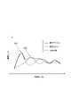
図3を参照して、第一実施形態に係る音響デバイス1の周波数特性について説明する。図3の横軸は振動の周波数(Hz)を示し、縦軸は振動の振幅(μm)を示している。図3は、音響デバイス1の周波数特性と、音響デバイス1を構成している振動ユニット2及び一対の支持部材4a,4bのそれぞれの周波数特性と、を示している。 The frequency characteristics of the acoustic device 1 according to the first embodiment will be described with reference to FIG. The horizontal axis of FIG. 3 indicates the vibration frequency (Hz), and the vertical axis indicates the vibration amplitude (μm). FIG. 3 shows the frequency characteristics of the acoustic device 1 and the frequency characteristics of each of the vibratingunit 2 and the pair ofsupport members 4a and 4b that constitute the acoustic device 1. FIG.

振動ユニット2の共振周波数は、一対の支持部材4a,4bの共振周波数と異なる。振動ユニット2の共振周波数と、一対の支持部材4a,4bの共振周波数とは、それぞれの最低共振周波数によって比較される。振動ユニット2の最低共振周波数は、たとえば、1kHzである。W1は、振動ユニット2の最低共振周波数を中心とする周波数帯域における振幅のピークを示している。W1の周波数帯域において、振動ユニット2の音圧特性が向上する。一対の支持部材4a,4bの最低共振周波数は、たとえば、1.5kHzである。W2は、一対の支持部材4a,4bの最低共振周波数を中心とする周波数帯域における振幅のピークを示している。W2の周波数帯域において、一対の支持部材4a,4bの音圧特性が向上する。 The resonance frequency of the vibratingunit 2 is different from the resonance frequencies of the pair ofsupport members 4a and 4b. The resonance frequency of the vibratingunit 2 and the resonance frequency of the pair ofsupport members 4a and 4b are compared by their lowest resonance frequencies. The lowest resonance frequency ofvibration unit 2 is, for example, 1 kHz. W1 indicates an amplitude peak in a frequency band centered on the lowest resonance frequency of the vibratingunit 2 . The sound pressure characteristics of the vibratingunit 2 are improved in the W1 frequency band. The lowest resonance frequency of the pair ofsupport members 4a and 4b is, for example, 1.5 kHz. W2 indicates an amplitude peak in a frequency band around the lowest resonance frequency of the pair ofsupport members 4a and 4b. In the W2 frequency band, the sound pressure characteristics of the pair ofsupport members 4a and 4b are improved.

図3に示されるように、音響デバイス1の周波数特性は、振動ユニット2の周波数特性と、一対の支持部材4a,4bの周波数特性とが合成されたものである。したがって、音響デバイス1では、振動ユニット2の最低共振周波数を中心とする周波数帯域と、一対の支持部材4a,4bの最低共振周波数を中心とする周波数帯域とにおいて音圧特性が向上する。 As shown in FIG. 3, the frequency characteristics of the acoustic device 1 are obtained by synthesizing the frequency characteristics of the vibratingunit 2 and the frequency characteristics of the pair ofsupport members 4a and 4b. Therefore, in the acoustic device 1, the sound pressure characteristics are improved in the frequency band around the lowest resonance frequency of the vibratingunit 2 and in the frequency band around the lowest resonance frequency of the pair ofsupport members 4a and 4b.

本実施形態に係る音響デバイス1は、振動ユニット2の共振周波数と、一対の支持部材4a,4bの共振周波数とが、異なっている。したがって、振動ユニット2の共振周波数と、一対の支持部材4a,4bの共振周波数とにおいて、音圧が増大する。この結果、音響デバイス1は、幅広い周波数帯域で、音圧特性を向上する。 In the acoustic device 1 according to this embodiment, the resonance frequency of the vibratingunit 2 and the resonance frequencies of the pair ofsupport members 4a and 4b are different. Therefore, the sound pressure increases at the resonance frequency of thevibration unit 2 and the resonance frequency of the pair ofsupport members 4a and 4b. As a result, the acoustic device 1 has improved sound pressure characteristics in a wide frequency band.

本実施形態に係る音響デバイス1では、各支持部材4a,4bは、振動板30に連結されている第一部分41と、基材に連結される第二部分42と、第一部分41と第二部分42との間に位置している第三部分43とを有している。第三部分43では、断面積が部分的に小さい。
各支持部材4a,4bが、断面積が部分的に小さい第三部分43を有している構成では、各支持部材4a,4bの共振周波数は、第三部分43の形状、すなわち断面積に応じて変化する。したがって、音響デバイス1では、各支持部材4a,4bの共振周波数が所望の周波数に容易かつ確実に調整され得る。
In the acoustic device 1 according to this embodiment, each of thesupport members 4a and 4b includes afirst portion 41 connected to thediaphragm 30, asecond portion 42 connected to the substrate, and thefirst portion 41 and the second portion. 42 and athird portion 43 . Thethird portion 43 has a partially smaller cross-sectional area.
In a configuration in which eachsupport member 4a, 4b has athird portion 43 with a partially smaller cross-sectional area, the resonance frequency of eachsupport member 4a, 4b depends on the shape, i.e., cross-sectional area, of thethird portion 43. change by Therefore, in the acoustic device 1, the resonance frequency of eachsupport member 4a, 4b can be easily and reliably adjusted to a desired frequency.

本実施形態に係る音響デバイス1では、振動板30は、各支持部材4a,4bが連結されている主面30bを含んでいる。各支持部材4a,4bは、主面30bを含む仮想平面P1と交差する方向に延在している。
各支持部材4a,4bが主面30bを含む仮想平面P1と交差する方向に延在している構成は、第一方向D1から見たときの、音響デバイス1のサイズを低減し得る。
In the acoustic device 1 according to this embodiment, thediaphragm 30 includes amain surface 30b to which thesupport members 4a and 4b are connected. Eachsupport member 4a, 4b extends in a direction intersecting with a virtual plane P1 including themain surface 30b.
The configuration in which eachsupport member 4a, 4b extends in the direction intersecting the imaginary plane P1 including themain surface 30b can reduce the size of the acoustic device 1 when viewed from the first direction D1.

本実施形態に係る音響デバイス1では、各溝43aは、湾曲面43bによって画成されている。
各溝43aが湾曲面43bによって画成されているため、各支持部材4a,4bが第三部分43においてたわみ変形するとき、第三部分43に発生する応力が分散される。よって、音響デバイス1では、第三部分43は、塑性変形し難い。
In the acoustic device 1 according to this embodiment, eachgroove 43a is defined by acurved surface 43b.
Since eachgroove 43a is defined by thecurved surface 43b, the stress generated in thethird portion 43 is dispersed when eachsupport member 4a, 4b bends in thethird portion 43. As shown in FIG. Therefore, in the acoustic device 1, thethird portion 43 is less likely to be plastically deformed.

(第二実施形態)
図4及び図5を参照して、第二実施形態に係る音響デバイス1の構成を説明する。図4は、第二実施形態に係る音響デバイス1の断面構成を示す図である。図5は、第二実施形態に係る音響デバイス1の周波数特性を示す図である。第二実施形態は、概ね、第一実施形態と類似又は同じである。第二実施形態は、各支持部材4a,4bが第四部分44を有している点において、第一実施形態と相違する。
(Second embodiment)
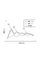
The configuration of the acoustic device 1 according to the second embodiment will be described with reference to FIGS. 4 and 5. FIG. FIG. 4 is a diagram showing a cross-sectional configuration of the acoustic device 1 according to the second embodiment. FIG. 5 is a diagram showing frequency characteristics of the acoustic device 1 according to the second embodiment. The second embodiment is generally similar or the same as the first embodiment. The second embodiment differs from the first embodiment in that eachsupport member 4 a , 4 b has afourth portion 44 .

本実施形態では、各支持部材4a,4bは、第一部分41と第二部分42との間に位置していると共に断面積が部分的に小さい第三部分43と、第一部分41と第二部分42との間に位置している第四部分44と、を有している。 In this embodiment, eachsupport member 4a, 4b includes athird portion 43, which is located between thefirst portion 41 and thesecond portion 42 and has a partially smaller cross-sectional area, and thefirst portion 41 and the second portion. and afourth portion 44 located between 42 .

第四部分44は、第三方向D3での各支持部材4a,4bの両端を含む一対の溝44aを有している。各主面40aは、溝44aを構成している面を含んでいる。溝44aは、各支持部材4a,4bの第三方向D3において互いに対向している一対の側面の一方から他方まで延在している。一対の溝44aは、仮想平面P2に対してそれぞれ面対称に位置している。支持部材4aにおいて、一対の溝44aは、第一部分41と第二部分42とが互いに対向している方向でのそれぞれの位置が一致するように形成されている。支持部材4bにおいても、一対の溝44aは、第一部分41と第二部分42とが互いに対向している方向でのそれぞれの位置が一致するように形成されている。 Thefourth portion 44 has a pair ofgrooves 44a including both ends of eachsupport member 4a, 4b in the third direction D3. Eachmajor surface 40a includessurfaces defining grooves 44a. Thegroove 44a extends from one to the other of a pair of side surfaces facing each other in the third direction D3 of eachsupport member 4a, 4b. The pair ofgrooves 44a are positioned symmetrically with respect to the virtual plane P2. In thesupport member 4a, the pair ofgrooves 44a are formed so that their respective positions in the direction in which thefirst portion 41 and thesecond portion 42 face each other match. Also in thesupport member 4b, the pair ofgrooves 44a are formed so that their respective positions in the direction in which thefirst portion 41 and thesecond portion 42 face each other are aligned.

本実施形態では、一対の溝44aを画成する面は、仮想平面P2に対して、それぞれ面対称に位置している。各溝44aは、各支持部材4a,4bの厚さ方向に形成されている。各主面40aは、各溝44aを画成する湾曲面44bを含んでいる。湾曲面44bは、たとえば、第三方向D3から見て、半円状の円弧を呈している。 In this embodiment, the surfaces defining the pair ofgrooves 44a are positioned symmetrically with respect to the virtual plane P2. Eachgroove 44a is formed in the thickness direction of eachsupport member 4a, 4b. Eachmajor surface 40a includescurved surfaces 44b that definerespective grooves 44a. Thecurved surface 44b has, for example, a semicircular arc when viewed from the third direction D3.

第四部分44は、一対の溝44aの位置において、部分的に断面積が小さい。本実施形態では、第四部分44の断面積は、第三部分43の断面積とは異なる。第四部分44の断面積は、第三部分43の断面積より大きい。第四部分44の断面積は、溝44aの形状に応じて変化する。第四部分44の断面積は、断面の位置に応じて変化する。具体的には、第四部分44の断面積は、第二方向D2において、一方の湾曲面43bと他方の湾曲面43bとの間の距離に応じて変化する。当該距離は、第四部分44の厚みである。第四部分44の厚みの最小値は、たとえば、0.1mm以上3mm以下である。第二方向D2における、第四部分44の厚みが最小になる位置は、たとえば、第三部分43の厚みが最小になる位置を基準に、5mm以上40mm以下、離間している。各支持部材4a,4bは、第三部分43と、第四部分44とにおいて、たわみ変形する。 Thefourth portion 44 has a partially small cross-sectional area at the position of the pair ofgrooves 44a. In this embodiment, the cross-sectional area of thefourth portion 44 is different from the cross-sectional area of thethird portion 43 . The cross-sectional area of thefourth portion 44 is larger than the cross-sectional area of thethird portion 43 . The cross-sectional area of thefourth portion 44 changes according to the shape of thegroove 44a. The cross-sectional area of thefourth portion 44 varies depending on the position of the cross-section. Specifically, the cross-sectional area of thefourth portion 44 changes according to the distance between onecurved surface 43b and the othercurved surface 43b in the second direction D2. The distance is the thickness of thefourth portion 44 . The minimum thickness of thefourth portion 44 is, for example, 0.1 mm or more and 3 mm or less. The position in the second direction D2 where the thickness of thefourth portion 44 is minimum is, for example, 5 mm or more and 40 mm or less away from the position where the thickness of thethird portion 43 is minimum. Eachsupport member 4a, 4b is flexurally deformed at thethird portion 43 and thefourth portion 44. As shown in FIG.

図5を参照して、第二実施形態に係る音響デバイス1の周波数特性について説明する。図5は、第二実施形態に係る音響デバイス1における、周波数と振幅の関係を示している。一対の支持部材4a,4bは、複数の部分においてたわみ変形するため、複数の振幅のピークを示す。W3は、一対の支持部材4a,4bの最低共振周波数とは異なる共振周波数を中心とする周波数帯域における振幅のピークを示している。一対の支持部材4a,4bの最低共振周波数とは異なる共振周波数は、たとえば、1kHzである。W3の周波数帯域において、一対の支持部材4a,4bの周波数特性が向上する。 The frequency characteristics of the acoustic device 1 according to the second embodiment will be described with reference to FIG. FIG. 5 shows the relationship between frequency and amplitude in the acoustic device 1 according to the second embodiment. Since the pair ofsupport members 4a and 4b are flexurally deformed in a plurality of portions, they exhibit a plurality of amplitude peaks. W3 indicates an amplitude peak in a frequency band around a resonance frequency different from the lowest resonance frequency of the pair ofsupport members 4a and 4b. A resonance frequency different from the lowest resonance frequency of the pair ofsupport members 4a and 4b is, for example, 1 kHz. In the W3 frequency band, the frequency characteristics of the pair ofsupport members 4a and 4b are improved.

図5に示されるように、音響デバイス1の周波数特性は、振動ユニット2の周波数特性と、一対の支持部材4a,4bの周波数特性とが合成されたものである。したがって、音響デバイス1では、振動ユニット2の最低共振周波数を中心とする周波数帯域と、一対の支持部材4a,4bの最低共振周波数を中心とする周波数帯域と、一対の支持部材4a,4bの最低共振周波数とは異なる共振周波数を中心とする周波数帯域とにおいて音圧特性が向上する。 As shown in FIG. 5, the frequency characteristics of the acoustic device 1 are obtained by synthesizing the frequency characteristics of the vibratingunit 2 and the frequency characteristics of the pair ofsupport members 4a and 4b. Therefore, in the acoustic device 1, the frequency band centered on the lowest resonance frequency of thevibration unit 2, the frequency band centered on the lowest resonance frequency of the pair ofsupport members 4a and 4b, and the lowest frequency band of the pair ofsupport members 4a and 4b Sound pressure characteristics are improved in a frequency band around a resonance frequency different from the resonance frequency.

本実施形態に係る音響デバイス1は、各支持部材4a,4bは、第四部分44を有している。第四部分44は、第一部分41と第二部分42との間に位置していると共に断面積が部分的に小さい。
各支持部材4a,4bが、断面積が部分的に小さい第四部分44を有している構成では、各支持部材4a,4bの共振周波数は、第三部分43の形状のほか、第四部分44の形状、すなわち断面積に応じても変化する。したがって、音響デバイス1では、各支持部材4a,4bの共振周波数が所望の周波数により一層容易かつ確実に調整され得る。
In the acoustic device 1 according to this embodiment, eachsupport member 4a, 4b has afourth portion 44. As shown in FIG. Thefourth portion 44 is located between thefirst portion 41 and thesecond portion 42 and has a partially small cross-sectional area.
In a configuration in which eachsupport member 4a, 4b has afourth portion 44 with a partially small cross-sectional area, the resonance frequency of eachsupport member 4a, 4b depends on the shape of thethird portion 43 as well as the shape of the fourth portion. It also changes according to the shape of 44, ie the cross-sectional area. Therefore, in the acoustic device 1, the resonance frequency of eachsupport member 4a, 4b can be adjusted to a desired frequency more easily and reliably.

(第三実施形態)
図6を参照して、第三実施形態に係る音響デバイス1の構成を説明する。図6は、第三実施形態に係る音響デバイス1の断面構成を示す図である。第三実施形態は、概ね、第一実施形態と類似又は同じである。第三実施形態は、各支持部材4a,4bが主面30bを含む仮想平面P1と平行な方向に延在している点において、第一実施形態と相違する。
(Third embodiment)
The configuration of the acoustic device 1 according to the third embodiment will be described with reference to FIG. FIG. 6 is a diagram showing a cross-sectional configuration of the acoustic device 1 according to the third embodiment. The third embodiment is generally similar or the same as the first embodiment. The third embodiment differs from the first embodiment in that eachsupport member 4a, 4b extends in a direction parallel to the virtual plane P1 including themain surface 30b.

本実施形態では、振動板30は、各支持部材4a,4bが連結されている主面30bを含んでおり、各支持部材4a,4bは、主面30bを含む仮想平面P1と平行な方向に延在している。たとえば、各支持部材4a,4bは、板状を呈しており、第二方向D2に延在している。各支持部材4a,4bは、第一方向D1で互いに対向している一対の主面40aと、第二方向D2で互いに対向している一対の側面40bとを含んでいる。第一部分41は、一方の主面40aにおいて振動板30に連結されている。一方の側面40bは、第二部分42において基材Bに連結されている。 In this embodiment, thediaphragm 30 includes amain surface 30b to which thesupport members 4a and 4b are connected, and thesupport members 4a and 4b extend in a direction parallel to the virtual plane P1 including themain surface 30b. extended. For example, eachsupport member 4a, 4b has a plate shape and extends in the second direction D2. Eachsupport member 4a, 4b includes a pair ofmain surfaces 40a facing each other in the first direction D1 and a pair ofside surfaces 40b facing each other in the second direction D2. Thefirst portion 41 is connected to thediaphragm 30 on onemain surface 40a. Oneside surface 40 b is connected to the base material B at thesecond portion 42 .

一対の支持部材4a,4bは、振動ユニット2の振動によって振動する。本実施形態では、振動ユニット2のたわみ振動によって、一対の支持部材4a,4bは、第一方向D1でたわみ振動する。本実施形態では、振動ユニット2のたわみ振動によって、一対の支持部材4a,4bは、第一方向D1でたわみ振動する。振動ユニット2が第一方向D1の一方に向かってたわみ変形するとき、一対の支持部材4a,4bが、第一方向D1の一方に向かってたわみ変形するように、音響デバイス1は、たわみ振動する。 The pair ofsupport members 4 a and 4 b vibrate due to the vibration of the vibratingunit 2 . In this embodiment, the pair ofsupport members 4a and 4b are flexurally vibrated in the first direction D1 by the flexural vibration of the vibratingunit 2. As shown in FIG. In this embodiment, the pair ofsupport members 4a and 4b are flexurally vibrated in the first direction D1 by the flexural vibration of the vibratingunit 2. As shown in FIG. When thevibration unit 2 is flexurally deformed in one direction of the first direction D1, the acoustic device 1 is flexurally vibrated so that the pair ofsupport members 4a and 4b are flexurally deformed in one direction of the first direction D1. .

本実施形態に係る音響デバイス1では、振動板30は、各支持部材4a,4bが連結されている主面30bを含んでいる。各支持部材4a,4bは、主面30bを含む仮想平面P1と平行な方向に延在している。
各支持部材4a,4bが主面30bを含む仮想平面P1と平行な方向に延在している構成は、第一方向D1での、音響デバイス1のサイズを低減し得る。
In the acoustic device 1 according to this embodiment, thediaphragm 30 includes amain surface 30b to which thesupport members 4a and 4b are connected. Eachsupport member 4a, 4b extends in a direction parallel to a virtual plane P1 including themain surface 30b.
A configuration in which eachsupport member 4a, 4b extends in a direction parallel to the imaginary plane P1 including themain surface 30b can reduce the size of the acoustic device 1 in the first direction D1.

(第四実施形態)
図7は、第四実施形態に係る音響デバイス1の断面構成を示す図である。第四実施形態は、概ね、第二実施形態及び第三実施形態と類似又は同じである。第四実施形態は、各支持部材4a,4bが主面30bを含む仮想平面P1と平行な方向に延在している点において、第二実施形態と相違する。第四実施形態は、各支持部材4a,4bが第四部分44を有している点において、第三実施形態と相違する。
(Fourth embodiment)
FIG. 7 is a diagram showing a cross-sectional configuration of the acoustic device 1 according to the fourth embodiment. The fourth embodiment is generally similar or the same as the second and third embodiments. The fourth embodiment differs from the second embodiment in that eachsupport member 4a, 4b extends in a direction parallel to a virtual plane P1 including themain surface 30b. The fourth embodiment differs from the third embodiment in that eachsupport member 4 a , 4 b has afourth portion 44 .

以上、本発明の実施形態について説明してきたが、本発明は必ずしも上述した実施形態に限定されるものではなく、その要旨を逸脱しない範囲で様々な変更が可能である。 Although the embodiments of the present invention have been described above, the present invention is not necessarily limited to the above-described embodiments, and various modifications can be made without departing from the scope of the invention.

(変形例)
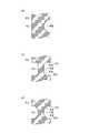
図8は、変形例に係る各支持部材4a,4bの断面構成を示す拡大図である。図8は、第三部分43の拡大図である。
第三部分43は、一対の溝43aを有さなくてもよい。図8の(a)に示される変形例では、第三部分43は、第三方向D3での両端を含む一つの溝43aを有している。図示は省略するが、第四部分44も、第三部分43と同様に、第三方向D3での両端を含む一つの溝44aを有していてもよい。
各主面40aは、第三部分43において、各溝43aを構成する湾曲面43bを含まなくてもよい。図8の(b)に示される変形例では、各主面40aは、第三部分43において、第三方向D3から見て、各溝43aを開口している一対の側面43cと、各溝43aの第二方向D2における底面を構成している底面43dと、一対の側面43cと底面43dとを互いに連結している一対の湾曲面43eと、を含んでいる。図示は省略するが、各主面40aは、第四部分44において、第三方向D3から見て、各溝44aを開口している一対の側面44cと、各溝44aの第二方向D2における底面を構成している底面44dと、一対の側面44cと底面44dとを互いに連結している一対の湾曲面44eと、を含んでいてもよい。
各主面40aは、第三部分43において、一対の側面43cと底面43dとを互いに連結している湾曲面43eを含まなくてもよい。図8の(c)に示される変形例では、各主面40aは、第三部分43において、一対の側面43cと底面43dとを互いに連結している側面43fを含んでいる。図示は省略するが、各主面40aは、第四部分44において、一対の側面44cと底面44dとを互いに連結している側面44fを含んでいてもよい。
一対の溝43aは、第三部分43の第三方向D3での端に達していなくてもよい。一対の溝44aは、第三部分43の第三方向D3での端に達していなくてもよい。
第一部分41と第二部分42とが互いに対向している方向における、一対の溝43aの幅は、互いに異なっていてもよい。各支持部材4a,4bの厚さ方向における、一対の溝43aの深さは、互いに異なっていてもよい。
(Modification)
FIG. 8 is an enlarged view showing a cross-sectional structure of eachsupport member 4a, 4b according to a modification. 8 is an enlarged view of thethird portion 43. FIG.
Thethird portion 43 may not have the pair ofgrooves 43a. In the modification shown in FIG. 8(a), thethird portion 43 has onegroove 43a including both ends in the third direction D3. Although not shown, thefourth portion 44 may also have onegroove 44a including both ends in the third direction D3, like thethird portion 43.
Eachmain surface 40a does not have to include thecurved surface 43b forming eachgroove 43a in thethird portion 43 . In the modification shown in FIG. 8(b), eachmain surface 40a of thethird portion 43 includes a pair of side surfaces 43c opening eachgroove 43a and eachgroove 43a when viewed from the third direction D3. and a pair ofcurved surfaces 43e connecting the pair of side surfaces 43c and thebottom surface 43d. Although not shown, eachmain surface 40a of thefourth portion 44 includes a pair of side surfaces 44c opening eachgroove 44a when viewed from the third direction D3, and a bottom surface of eachgroove 44a in the second direction D2. and a pair of curved surfaces 44e connecting the pair of side surfaces 44c and the bottom surface 44d.
Eachmain surface 40a may not include thecurved surface 43e that connects the pair of side surfaces 43c andbottom surface 43d in thethird portion 43. As shown in FIG. In the modification shown in FIG. 8(c), eachmain surface 40a includes aside surface 43f connecting a pair of side surfaces 43c andbottom surface 43d in thethird portion 43 to each other. Although illustration is omitted, eachmain surface 40a may include a side surface 44f that connects the pair of side surfaces 44c and bottom surface 44d in thefourth portion 44 to each other.
The pair ofgrooves 43a may not reach the end of thethird portion 43 in the third direction D3. The pair ofgrooves 44a may not reach the end of thethird portion 43 in the third direction D3.
The width of the pair ofgrooves 43a in the direction in which thefirst portion 41 and thesecond portion 42 face each other may be different from each other. The depth of the pair ofgrooves 43a in the thickness direction of eachsupport member 4a, 4b may be different from each other.

圧電素子10は、複数の内部電極16,17,18を備えない単板の圧電素子であってもよい。複数の内部電極16,17,18を備えない圧電素子10では、一対の主面11a,11bに外部電極が電気的に接続されてもよい。すなわち、振動ユニット2は、ユニモルフ構造の振動子を構成してもよい。振動ユニット2は、当該圧電素子10の伸縮によって、第一方向D1にたわみ振動してもよい。 Thepiezoelectric element 10 may be a single plate piezoelectric element without the plurality ofinternal electrodes 16 , 17 , 18 . In thepiezoelectric element 10 without a plurality ofinternal electrodes 16, 17, 18, external electrodes may be electrically connected to the pair ofmain surfaces 11a, 11b. That is, thevibration unit 2 may constitute a vibrator with a unimorph structure. Thevibration unit 2 may flexure and vibrate in the first direction D<b>1 due to expansion and contraction of thepiezoelectric element 10 .

第四部分44の断面積は、第三部分43の断面積より小さくてもよい。第四部分44は、断面積が部分的に小さければよい。
第四部分44の断面積は、第三部分43の断面積と等しくてもよい。第四部分44は、断面積が部分的に小さければよい。
The cross-sectional area of thefourth portion 44 may be smaller than the cross-sectional area of thethird portion 43 . Thefourth portion 44 may have a partially small cross-sectional area.
The cross-sectional area offourth portion 44 may be equal to the cross-sectional area ofthird portion 43 . Thefourth portion 44 may have a partially small cross-sectional area.

各支持部材4a,4bは、第三部分43及び第四部分44以外に、さらに、断面積が部分的に小さい部分を有していてもよい。すなわち、各支持部材4a,4bは、三つ以上の断面積が部分的に小さい部分を有していてもよい。
各支持部材4a,4bが、三つ以上の断面積が部分的に小さい部分を有している構成では、各支持部材4a,4bの共振周波数は、三つ以上の断面積が部分的に小さい部分の形状、すなわち断面積に応じても変化する。したがって、本構成では、各支持部材4a,4bの共振周波数が所望の周波数により一層容易かつ確実に調整され得る。
Each of thesupport members 4a, 4b may have a portion with a partially smaller cross-sectional area in addition to thethird portion 43 and thefourth portion 44. As shown in FIG. That is, each of thesupport members 4a and 4b may have three or more portions with partially small cross-sectional areas.
In a configuration in which eachsupport member 4a, 4b has three or more small cross-sectional area portions, the resonance frequency of eachsupport member 4a, 4b is three or more small cross-sectional area portions. It also varies depending on the shape of the part, ie the cross-sectional area. Therefore, in this configuration, the resonance frequency of eachsupport member 4a, 4b can be more easily and reliably adjusted to a desired frequency.

各支持部材4a,4bは、第三方向D3で、複数の部分に分割されていてもよい。たとえば、各支持部材4a,4bは、第三方向D3で互いに離間している複数の柱形状の部分に分割されていてもよい。 Eachsupport member 4a, 4b may be divided into a plurality of parts in the third direction D3. For example, eachsupport member 4a, 4b may be divided into a plurality of pillar-shaped portions spaced apart from each other in the third direction D3.

1…音響デバイス、2…振動ユニット、4a,4b…支持部材、10…圧電素子、30a,30b…主面、30…振動板、31…第一領域、32,33…第二領域、41…第一部分、42…第二部分、43…第三部分、44…第四部分、B…基材、P1,P2…仮想平面。 DESCRIPTION OF SYMBOLS 1...Acoustic device 2...Vibration unit 4a, 4b...Support member 10...Piezoelectric element 30a, 30b...Main surface 30...Diaphragm 31...First region 32, 33...Second region 41...First part 42...Second part 43...Third part 44... Fourth part B... Base material P1, P2... Virtual plane.

Claims (6)

Translated fromJapanese
基材に配置される音響デバイスであって、
圧電素子と、前記圧電素子が接合されている振動板とを有しており、前記圧電素子の伸縮によって振動する振動ユニットと、
前記振動ユニットを前記基材に支持し、前記振動ユニットの振動によって振動する複数の支持部材と、を備え、
前記振動板は、前記圧電素子が接合されている第一領域と、前記第一領域の両側に位置している一対の第二領域とを含み、
前記複数の支持部材は、前記一対の第二領域のうち対応する第二領域にそれぞれ配置されており、
前記振動ユニットの共振周波数は、前記複数の支持部材の共振周波数と異なる、音響デバイス。
An acoustic device disposed on a substrate, comprising:
a vibration unit having a piezoelectric element and a vibration plate to which the piezoelectric element is bonded, and vibrating due to expansion and contraction of the piezoelectric element;
a plurality of support members that support the vibration unit on the base material and vibrate due to vibration of the vibration unit;
The diaphragm includes a first region to which the piezoelectric element is bonded and a pair of second regions located on both sides of the first region,
The plurality of support members are arranged in corresponding second regions of the pair of second regions,
The acoustic device, wherein the resonance frequency of the vibrating unit is different from the resonance frequencies of the plurality of support members.
各前記支持部材は、
前記振動板に連結されている第一部分と、
前記基材に連結される第二部分と、
前記第一部分と前記第二部分との間に位置していると共に断面積が部分的に小さい第三部分と、
を有している、請求項1に記載の音響デバイス。
each said support member,
a first portion coupled to the diaphragm;
a second portion coupled to the substrate;
a third portion located between the first portion and the second portion and having a partially smaller cross-sectional area;
The acoustic device of claim 1, comprising:
各前記支持部材は、前記第一部分と前記第二部分との間に位置していると共に断面積が部分的に小さい第四部分を有している、請求項2に記載の音響デバイス。 3. The acoustic device of claim 2, wherein each support member has a fourth portion of partially reduced cross-sectional area located between the first portion and the second portion. 前記振動板は、各前記支持部材が連結されている主面を含んでおり、
各前記支持部材は、前記主面を含む仮想平面と交差する方向に延在している、請求項1~3何れか一項に記載の音響デバイス。
the diaphragm includes a main surface to which each of the support members is connected;
The acoustic device according to any one of claims 1 to 3, wherein each of said support members extends in a direction intersecting a virtual plane including said main surface.
前記振動板は、各前記支持部材が連結されている主面を含んでおり、
各前記支持部材は、前記主面を含む仮想平面と平行な方向に延在している、請求項1~3何れか一項に記載の音響デバイス。
the diaphragm includes a main surface to which each of the support members is connected;
The acoustic device according to any one of claims 1 to 3, wherein each said support member extends in a direction parallel to a virtual plane including said main surface.
前記振動板及び各前記支持部材は、金属からなる、請求項1~5何れか一項に記載の音響デバイス。 The acoustic device according to any one of claims 1 to 5, wherein said diaphragm and each said support member are made of metal.
JP2021092395A2021-06-012021-06-01 Acoustic DevicesActiveJP7663415B2 (en)

Priority Applications (1)

Application NumberPriority DateFiling DateTitle
JP2021092395AJP7663415B2 (en)2021-06-012021-06-01 Acoustic Devices

Applications Claiming Priority (1)

Application NumberPriority DateFiling DateTitle
JP2021092395AJP7663415B2 (en)2021-06-012021-06-01 Acoustic Devices

Publications (2)

Publication NumberPublication Date
JP2022184499Atrue JP2022184499A (en)2022-12-13
JP7663415B2 JP7663415B2 (en)2025-04-16

Family

ID=84437978

Family Applications (1)

Application NumberTitlePriority DateFiling Date
JP2021092395AActiveJP7663415B2 (en)2021-06-012021-06-01 Acoustic Devices

Country Status (1)

CountryLink
JP (1)JP7663415B2 (en)

Citations (4)

* Cited by examiner, † Cited by third party
Publication numberPriority datePublication dateAssigneeTitle
JPH01176200A (en)*1987-12-291989-07-12Nec CorpPiezoelectric diaphragm
JPH0470100A (en)*1990-07-091992-03-05Sumitomo Special Metals Co LtdTransparent speaker
JP2006245975A (en)*2005-03-032006-09-14Taiyo Yuden Co LtdPiezoelectric sound generator and electronic apparatus
WO2011074579A1 (en)*2009-12-152011-06-23日本電気株式会社Actuator, piezoelectric actuator, electronic device, and method for attenuating vibration and converting vibration direction

Patent Citations (4)

* Cited by examiner, † Cited by third party
Publication numberPriority datePublication dateAssigneeTitle
JPH01176200A (en)*1987-12-291989-07-12Nec CorpPiezoelectric diaphragm
JPH0470100A (en)*1990-07-091992-03-05Sumitomo Special Metals Co LtdTransparent speaker
JP2006245975A (en)*2005-03-032006-09-14Taiyo Yuden Co LtdPiezoelectric sound generator and electronic apparatus
WO2011074579A1 (en)*2009-12-152011-06-23日本電気株式会社Actuator, piezoelectric actuator, electronic device, and method for attenuating vibration and converting vibration direction

Also Published As

Publication numberPublication date
JP7663415B2 (en)2025-04-16

Similar Documents

PublicationPublication DateTitle
JP5594435B2 (en) Ultrasonic transducer
CN101313628B (en)Electroacoustic transducer
CN103444205B (en)Acoustic generator and employ the generating device of this acoustic generator
US8072119B2 (en)Piezoelectric component
US12120483B2 (en)Audio device
US8304962B2 (en)Ultrasonic motor
JP2022186216A (en)acoustic device
JP7663415B2 (en) Acoustic Devices
KR101010738B1 (en) Piezoelectric speaker
JP7354575B2 (en) Piezoelectric elements, vibration devices and electronic equipment
JP2022074823A (en)Vibration device
JPS6412111B2 (en)
JP6965742B2 (en) Piezoelectric element
JP7151517B2 (en) audio equipment and electronic equipment
JP7405042B2 (en) vibration device
JP7706891B2 (en) Vibration Device
JP7550066B2 (en) Vibration Device
JP7671163B2 (en) Acoustic Devices
JP7641083B2 (en) Vibration Device
JP7003741B2 (en) Vibration devices and piezoelectric elements
JP5129184B2 (en) Ultrasonic motor
JP2019118009A (en)Vibration device
JP2022184332A (en)vibration device
JP2022181587A (en)vibration device
JP2000115890A (en)Piezoelectric sounder and its manufacture

Legal Events

DateCodeTitleDescription
A621Written request for application examination

Free format text:JAPANESE INTERMEDIATE CODE: A621

Effective date:20240208

A131Notification of reasons for refusal

Free format text:JAPANESE INTERMEDIATE CODE: A131

Effective date:20241022

A521Request for written amendment filed

Free format text:JAPANESE INTERMEDIATE CODE: A523

Effective date:20241217

TRDDDecision of grant or rejection written
A01Written decision to grant a patent or to grant a registration (utility model)

Free format text:JAPANESE INTERMEDIATE CODE: A01

Effective date:20250401

A61First payment of annual fees (during grant procedure)

Free format text:JAPANESE INTERMEDIATE CODE: A61

Effective date:20250404

R150Certificate of patent or registration of utility model

Ref document number:7663415

Country of ref document:JP

Free format text:JAPANESE INTERMEDIATE CODE: R150


[8]ページ先頭

©2009-2025 Movatter.jp