JP2022174781A - Ultrasonic diagnostic device and diagnosis support method - Google Patents
Ultrasonic diagnostic device and diagnosis support methodDownload PDFInfo
- Publication number
- JP2022174781A JP2022174781AJP2021080736AJP2021080736AJP2022174781AJP 2022174781 AJP2022174781 AJP 2022174781AJP 2021080736 AJP2021080736 AJP 2021080736AJP 2021080736 AJP2021080736 AJP 2021080736AJP 2022174781 AJP2022174781 AJP 2022174781A
- Authority
- JP
- Japan
- Prior art keywords
- mark
- reliability
- lesion
- frame data
- lesion candidate
- Prior art date
- Legal status (The legal status is an assumption and is not a legal conclusion. Google has not performed a legal analysis and makes no representation as to the accuracy of the status listed.)
- Granted
Links
Images


Classifications
- A—HUMAN NECESSITIES
- A61—MEDICAL OR VETERINARY SCIENCE; HYGIENE
- A61B—DIAGNOSIS; SURGERY; IDENTIFICATION
- A61B8/00—Diagnosis using ultrasonic, sonic or infrasonic waves
- A61B8/52—Devices using data or image processing specially adapted for diagnosis using ultrasonic, sonic or infrasonic waves
- A61B8/5292—Devices using data or image processing specially adapted for diagnosis using ultrasonic, sonic or infrasonic waves using additional data, e.g. patient information, image labeling, acquisition parameters
- A—HUMAN NECESSITIES
- A61—MEDICAL OR VETERINARY SCIENCE; HYGIENE
- A61B—DIAGNOSIS; SURGERY; IDENTIFICATION
- A61B8/00—Diagnosis using ultrasonic, sonic or infrasonic waves
- A61B8/44—Constructional features of the ultrasonic, sonic or infrasonic diagnostic device
- A61B8/4411—Device being modular
- A—HUMAN NECESSITIES
- A61—MEDICAL OR VETERINARY SCIENCE; HYGIENE
- A61B—DIAGNOSIS; SURGERY; IDENTIFICATION
- A61B8/00—Diagnosis using ultrasonic, sonic or infrasonic waves
- A61B8/08—Clinical applications
- A61B8/0833—Clinical applications involving detecting or locating foreign bodies or organic structures
- A61B8/085—Clinical applications involving detecting or locating foreign bodies or organic structures for locating body or organic structures, e.g. tumours, calculi, blood vessels, nodules
- A—HUMAN NECESSITIES
- A61—MEDICAL OR VETERINARY SCIENCE; HYGIENE
- A61B—DIAGNOSIS; SURGERY; IDENTIFICATION
- A61B8/00—Diagnosis using ultrasonic, sonic or infrasonic waves
- A61B8/08—Clinical applications
- A61B8/0825—Clinical applications for diagnosis of the breast, e.g. mammography
- A—HUMAN NECESSITIES
- A61—MEDICAL OR VETERINARY SCIENCE; HYGIENE
- A61B—DIAGNOSIS; SURGERY; IDENTIFICATION
- A61B8/00—Diagnosis using ultrasonic, sonic or infrasonic waves
- A61B8/44—Constructional features of the ultrasonic, sonic or infrasonic diagnostic device
- A61B8/4483—Constructional features of the ultrasonic, sonic or infrasonic diagnostic device characterised by features of the ultrasound transducer
- A61B8/4488—Constructional features of the ultrasonic, sonic or infrasonic diagnostic device characterised by features of the ultrasound transducer the transducer being a phased array
- A—HUMAN NECESSITIES
- A61—MEDICAL OR VETERINARY SCIENCE; HYGIENE
- A61B—DIAGNOSIS; SURGERY; IDENTIFICATION
- A61B8/00—Diagnosis using ultrasonic, sonic or infrasonic waves
- A61B8/46—Ultrasonic, sonic or infrasonic diagnostic devices with special arrangements for interfacing with the operator or the patient
- A61B8/461—Displaying means of special interest
- A—HUMAN NECESSITIES
- A61—MEDICAL OR VETERINARY SCIENCE; HYGIENE
- A61B—DIAGNOSIS; SURGERY; IDENTIFICATION
- A61B8/00—Diagnosis using ultrasonic, sonic or infrasonic waves
- A61B8/52—Devices using data or image processing specially adapted for diagnosis using ultrasonic, sonic or infrasonic waves
- A61B8/5207—Devices using data or image processing specially adapted for diagnosis using ultrasonic, sonic or infrasonic waves involving processing of raw data to produce diagnostic data, e.g. for generating an image
- A—HUMAN NECESSITIES
- A61—MEDICAL OR VETERINARY SCIENCE; HYGIENE
- A61B—DIAGNOSIS; SURGERY; IDENTIFICATION
- A61B8/00—Diagnosis using ultrasonic, sonic or infrasonic waves
- A61B8/52—Devices using data or image processing specially adapted for diagnosis using ultrasonic, sonic or infrasonic waves
- A61B8/5215—Devices using data or image processing specially adapted for diagnosis using ultrasonic, sonic or infrasonic waves involving processing of medical diagnostic data
- G—PHYSICS
- G06—COMPUTING OR CALCULATING; COUNTING
- G06T—IMAGE DATA PROCESSING OR GENERATION, IN GENERAL
- G06T7/00—Image analysis
- G06T7/0002—Inspection of images, e.g. flaw detection
- G06T7/0012—Biomedical image inspection
- G—PHYSICS
- G06—COMPUTING OR CALCULATING; COUNTING
- G06T—IMAGE DATA PROCESSING OR GENERATION, IN GENERAL
- G06T2207/00—Indexing scheme for image analysis or image enhancement
- G06T2207/10—Image acquisition modality
- G06T2207/10132—Ultrasound image
- G—PHYSICS
- G06—COMPUTING OR CALCULATING; COUNTING
- G06T—IMAGE DATA PROCESSING OR GENERATION, IN GENERAL
- G06T2207/00—Indexing scheme for image analysis or image enhancement
- G06T2207/20—Special algorithmic details
- G06T2207/20081—Training; Learning
- G—PHYSICS
- G06—COMPUTING OR CALCULATING; COUNTING
- G06T—IMAGE DATA PROCESSING OR GENERATION, IN GENERAL
- G06T2207/00—Indexing scheme for image analysis or image enhancement
- G06T2207/20—Special algorithmic details
- G06T2207/20084—Artificial neural networks [ANN]
- G—PHYSICS
- G06—COMPUTING OR CALCULATING; COUNTING
- G06T—IMAGE DATA PROCESSING OR GENERATION, IN GENERAL
- G06T2207/00—Indexing scheme for image analysis or image enhancement
- G06T2207/30—Subject of image; Context of image processing
- G06T2207/30004—Biomedical image processing
- G06T2207/30096—Tumor; Lesion
Landscapes
- Health & Medical Sciences (AREA)
- Life Sciences & Earth Sciences (AREA)
- Engineering & Computer Science (AREA)
- Physics & Mathematics (AREA)
- General Health & Medical Sciences (AREA)
- Medical Informatics (AREA)
- Nuclear Medicine, Radiotherapy & Molecular Imaging (AREA)
- Radiology & Medical Imaging (AREA)
- Animal Behavior & Ethology (AREA)
- Heart & Thoracic Surgery (AREA)
- Veterinary Medicine (AREA)
- Public Health (AREA)
- Biophysics (AREA)
- Pathology (AREA)
- Biomedical Technology (AREA)
- Surgery (AREA)
- Molecular Biology (AREA)
- Computer Vision & Pattern Recognition (AREA)
- General Physics & Mathematics (AREA)
- Quality & Reliability (AREA)
- Theoretical Computer Science (AREA)
- Vascular Medicine (AREA)
- Gynecology & Obstetrics (AREA)
- Ultra Sonic Daignosis Equipment (AREA)
Abstract
Translated fromJapaneseDescription
Translated fromJapanese本開示は、超音波診断装置及び診断支援方法に関し、特に、検査者に対して病変部候補を通知する技術に関する。 TECHNICAL FIELD The present disclosure relates to an ultrasonic diagnostic apparatus and a diagnostic support method, and more particularly to a technique for notifying an examiner of lesion candidates.
超音波検査においては、被検者の表面に当接されたプローブが被検者の表面に沿って走査される。その走査の過程において、表示器に表示されるリアルタイム断層画像が観察され、その観察を通じて病変部の有無が判断される。病変部が見つかった場合、病変部が詳しく検査される。 In ultrasonic examination, a probe brought into contact with the surface of a subject is scanned along the surface of the subject. During the scanning process, a real-time tomographic image displayed on a display is observed, and the presence or absence of a lesion is determined through the observation. If a lesion is found, the lesion is examined in detail.
動的に変化する断層画像上において、一時的に現れる病変部を視覚的に特定することは容易ではない。病変部の特定を支援する技術として、CADe(Computer Aided Detection)がある。その技術は、例えば、断層画像に含まれる病変部候補を検出し、検出された病変部候補を検査者に通知するものである。例えば、断層画像上に病変部候補を囲むマークが表示される。CADeは、CAD(Computer Aided Diagnosis)と共に利用され又はCADに含まれるものである。CADはCADxとも表記される。 It is not easy to visually identify a temporarily appearing lesion on a dynamically changing tomographic image. CADe (Computer Aided Detection) is available as a technique for assisting identification of lesions. The technique detects, for example, a lesion candidate included in a tomographic image, and notifies the inspector of the detected lesion candidate. For example, a mark surrounding the lesion candidate is displayed on the tomographic image. CADe is used with or included in CAD (Computer Aided Diagnosis). CAD is also written as CADx.
特許文献1には、CAD機能を備えた超音波診断装置が開示されている。特許文献1には、病変部候補を通知するマークの表示態様を変更することについては記載されていない。特許文献2には、CAD機能を備えた超音波診断装置において、病変部候補を通知するマークの表示態様を変更することが記載されている。しかし、その技術は、検査者ごとに病変部候補を見逃す傾向が異なることを前提とし、検査者ごとに病変部候補の見逃しを防止することをその目的とするものである。すなわち、その技術は、病変部候補が病変部である可能性の大小とは無関係である。特許文献3には、CAD機能を備えた超音波診断装置において、病変部候補の検出の信頼度が閾値以上である場合に診断名を表示することが記載されている。
なお、本願明細書において、病変部は、疾患の可能性がある部位又は精査しておく必要性のある部位を意味する。病変部候補は、検査者による病変部の特定及び診断を支援するために検出された部位を意味する。 In the specification of the present application, a lesion means a site that may have a disease or a site that needs to be closely examined. A lesion candidate means a site detected to assist an examiner in identifying and diagnosing a lesion.
病変部候補を通知するマークを表示する場合において、病変部候補の検出の信頼度をマークの形態の変更により表現することが考えられる。その技術を採用した場合、病変部候補の検出初期においては、不安定な検出状態になり易く、信頼度が変化し易い。つまり、マーク表示開始直後においてはマークの形態が変化し易い。そのような形態の変化は、超音波画像の観察の妨げになるものであり、具体的には、超音波画像を観察している検査者にとって目障りとなるものである。 When displaying a mark for notifying a lesion candidate, it is conceivable to express the reliability of detection of the lesion candidate by changing the form of the mark. When this technique is employed, the detection state tends to be unstable and the reliability tends to change in the early stage of detection of lesion candidates. In other words, the shape of the mark is likely to change immediately after the start of mark display. Such a morphological change interferes with observation of the ultrasonic image, and more specifically, it is an eyesore for the examiner who is observing the ultrasonic image.
本開示の目的は、病変部候補を通知するマークの形態の変化により病変部候補の検出の信頼度を表現する場合において、マークの形態の望ましくない変化を制限することにある。 An object of the present disclosure is to limit undesirable changes in the shape of the mark when expressing the reliability of detection of the lesion candidate by changing the shape of the mark that notifies the lesion candidate.
本開示に係る超音波診断装置は、超音波ビームの走査を繰り返すことにより得られたフレームデータ列を受け入れ、フレームデータごとに当該フレームデータに含まれる病変部候補が病変部である可能性を示す信頼度を演算する演算部と、前記フレームデータ列に基づいて形成された超音波画像上に前記病変部候補を通知するマークを表示する表示制御部であって、前記病変部候補の検出が連続している連続検出状態において前記マークを継続的に表示する表示制御部と、を含み、前記表示制御部は、前記連続検出状態において、前記病変部候補が最初に検出された時点から形態不変期間を経過するまで前記マークの形態を固定すると共に前記形態不変期間の経過後に前記信頼度に応じて前記マークの形態を変更する、ことを特徴とする。 An ultrasonic diagnostic apparatus according to the present disclosure accepts a frame data string obtained by repeating scanning of an ultrasonic beam, and indicates the possibility that a lesion candidate included in the frame data is a lesion for each frame data. and a display control unit for displaying a mark notifying the lesion candidate on the ultrasonic image formed based on the frame data string, wherein the detection of the lesion candidate is continuous. a display control unit for continuously displaying the mark in the continuous detection state, wherein the display control unit controls, in the continuous detection state, the morphology unchanged period from the time when the lesion candidate is first detected. and changing the form of the mark according to the reliability after the period of no change in form has passed.
本開示に係る診断支援方法は、超音波ビームの走査を繰り返すことにより得られたフレームデータ列を構成するフレームデータごとに、当該フレームデータに含まれる病変部候補が病変部である可能性を示す信頼度を演算する工程と、前記フレームデータ列に基づいて形成された超音波画像上に前記病変部候補を通知するマークを表示する工程と、を含み、前記病変部候補の検出が連続している連続検出状態において前記マークが継続的に表示され、前記マークの継続的な表示に際して、前記病変部候補が最初に検出された時点から形態不変期間を経過するまで前記マークの形態が固定され、その後、前記信頼度に応じて前記マークの形態が変更される、ことを特徴とする。 A diagnosis support method according to the present disclosure indicates the possibility that a lesion candidate included in the frame data is a lesion for each frame data that constitutes a frame data string obtained by repeating scanning with an ultrasonic beam. and displaying a mark notifying the lesion candidate on the ultrasonic image formed based on the frame data string, wherein the detection of the lesion candidate is continuously performed. the mark is continuously displayed in a continuous detection state, and when the mark is continuously displayed, the shape of the mark is fixed from the time when the lesion candidate is first detected until a shape invariant period elapses; After that, the form of the mark is changed according to the reliability.
本開示によれば、病変部候補を通知するマークの形態の変化により病変部候補の検出の信頼度を表現する場合において、マークの形態の望ましくない変化を制限できる。 Advantageous Effects of Invention According to the present disclosure, it is possible to limit undesirable changes in the form of a mark when expressing the reliability of detection of a lesion candidate by changing the form of the mark that notifies the lesion candidate.
以下、実施形態を図面に基づいて説明する。 Hereinafter, embodiments will be described based on the drawings.
(1)実施形態の概要
実施形態に係る超音波診断装置は、演算部、及び、表示制御部を有する。演算部は、超音波ビームの走査を繰り返すことにより得られたフレームデータ列を受け入れ、フレームデータごとに当該フレームデータに含まれる病変部候補が病変部である可能性を示す信頼度を演算する。表示制御部は、フレームデータ列に基づいて形成された超音波画像上に病変部候補を通知するマークを表示する。病変部候補の検出が連続している連続検出状態においてマークが継続的に表示される。表示制御部は、連続検出状態において、病変部候補が最初に検出された時点から形態不変期間を経過するまでマークの形態を固定すると共に形態不変期間の経過後に信頼度に応じてマークの形態を変更する。(1) Outline of Embodiment An ultrasonic diagnostic apparatus according to an embodiment has an arithmetic unit and a display control unit. The computing unit receives a frame data string obtained by repeating the scanning of the ultrasonic beam, and computes the reliability indicating the possibility that the lesion candidate included in the frame data is a lesion for each frame data. The display control unit displays a mark for notifying a lesion candidate on the ultrasonic image formed based on the frame data string. The mark is continuously displayed in the continuous detection state in which lesion candidates are continuously detected. In the continuous detection state, the display control unit fixes the shape of the mark from the time when the lesion candidate is first detected until the shape constant period elapses, and after the shape constant period elapses, changes the shape of the mark according to the reliability. change.
上記構成によれば、病変部候補が検出された場合、形態不変期間が経過するまで、マークの形態が固定される。病変部候補の検出初期においては、通常、信頼度が不安定となるため、その期間においては信頼度の表示を停止させるものである。これによれば、検出初期におけるマーク形態の変化に起因して生じる問題、例えば、検査者にとってマーク形態の変化が目障りとなることを回避できる。よって、検出初期において、マークで通知された部位の観察に意識を集中させることが可能となる。検出初期を過ぎた場合、つまり形態不変期間が経過した場合、マークの形態が変化しても、通常、その変化はゆっくりとしたものなので、上記問題は生じ難い。なお、典型的には、検出初期はプローブを比較的に速く動かしている期間であり、その後にプローブが停止された上で、プローブの位置や姿勢がゆっくりと調整されつつ、病変部候補が詳しく観察される。 According to the above configuration, when a lesion candidate is detected, the shape of the mark is fixed until the shape invariant period elapses. In the early stage of detection of a lesion candidate, the reliability is usually unstable, so the display of the reliability is stopped during that period. According to this, it is possible to avoid problems caused by a change in the shape of the mark at the initial stage of detection, for example, the change in the shape of the mark being an eyesore for the inspector. Therefore, at the initial stage of detection, it is possible to concentrate on observing the site notified by the mark. When the initial stage of detection has passed, that is, when the shape invariant period has passed, even if the shape of the mark changes, the change is usually slow, so the above problem is unlikely to occur. Typically, the initial stage of detection is a period in which the probe is moved relatively quickly. Observed.
実施形態において、表示制御部は、連続検出状態において、形態不変期間の経過後に信頼度が高くなるに従ってマークの形態を段階的に変更する。マークの形態を連続的に変化させてもよいが、マークの形態を段階的に変化させれば信頼度の変化を認識し易くなる。 In the embodiment, in the continuous detection state, the display control unit changes the form of the mark step by step as the reliability increases after the morphology invariant period has elapsed. The form of the mark may be changed continuously, but if the form of the mark is changed stepwise, it becomes easier to recognize the change in reliability.
実施形態においては、信頼度軸上に非表示範囲及び表示範囲が定められる。表示範囲は最下位区間を含む複数の区間に分けられる。形態不変期間においてマークの形態は初期形態である。形態不変期間の経過後においてマークの形態は複数の区間に対応する複数の形態の中のいずれかである。複数の形態には最下位区間に対応する初期形態が含まれる。形態不変期間において表示されるマーク形態と最下位区間に対応するマーク形態とを同じにすれば、形態不変期間の経過時点での形態変化の頻度を少なくできる。 In embodiments, a hidden range and a visible range are defined on the confidence axis. The display range is divided into multiple intervals including the lowest interval. The shape of the mark is the initial shape in the shape-invariant period. After the morphology invariant period has elapsed, the mark morphology is one of a plurality of morphologies corresponding to a plurality of sections. The multiple forms include an initial form corresponding to the lowest interval. If the form of the mark displayed during the non-changing form period and the form of the mark corresponding to the lowest section are the same, the frequency of change in form after the period of non-changing form has elapsed can be reduced.
実施形態において、マークの形態の段階的な変更には、マークの太さの段階的な変更、マークの色の段階的な変更、マークの透明度の段階的な変更、及び、マークを構成する線の種類の段階的な変更、の内の少なくとも1つが含まれる。マークが病変部位候補を包含するエリアの4隅を特定する4つの表示要素により構成されてもよい。マークがペイントされたエリアであってもよい。 In the embodiment, the gradual change of the form of the mark includes gradual change of the thickness of the mark, gradual change of the color of the mark, gradual change of the transparency of the mark, and gradual change of the line that constitutes the mark. a gradual change of the type of The mark may consist of four display elements that identify the four corners of the area containing the candidate lesion site. It may be an area with painted marks.
実施形態において、表示制御部は、信頼度が閾値よりも大きくなった場合にマークを表示し、信頼度が閾値よりも小さくなった場合にマークを消去する。形態不変期間の経過前に信頼度が閾値よりも小さくなった場合に、超音波画像上のマークが消去される。この構成によれば、一時的検出の事実を通知でき、同時に、マークが超音波画像の観察上の妨げとなることを防止できる。 In the embodiment, the display control unit displays the mark when the reliability is greater than the threshold, and erases the mark when the reliability is less than the threshold. The mark on the ultrasound image is erased if the reliability becomes smaller than the threshold before the morphology invariant period elapses. According to this configuration, the fact of temporary detection can be notified, and at the same time, the mark can be prevented from interfering with observation of the ultrasonic image.
実施形態において、演算部は、フレームデータごとに、当該フレームデータに含まれる病変部候補の属性を判定する。表示制御部は、連続検出状態において、形態不変期間を経過後に、信頼度及び属性の組み合わせに応じてマークの形態を変更する。この構成によれば、マークの形態を通じて、信頼度の大小を認識でき且つ病変部候補の属性を認識できる。属性の概念には、例えば、病名、病態、悪性度、等が含まれる。 In the embodiment, the calculation unit determines attributes of candidate lesions included in the frame data for each frame data. In the continuous detection state, the display control unit changes the form of the mark according to the combination of the reliability and the attribute after the form invariant period elapses. According to this configuration, it is possible to recognize the degree of reliability and the attribute of the lesion candidate through the shape of the mark. The concept of attributes includes, for example, disease name, disease state, malignancy, and the like.
実施形態において、演算部は、フレームデータごとに、当該フレームデータに含まれる病変部候補の属性として重要属性及び非重要属性のいずれかを判定する。表示制御部は、重要属性が判定された場合に、連続検出状態において、形態不変期間の経過後に、信頼度に応じてマークの形態を変更する。一方、表示制御部は、非重要属性が判定された場合に、連続検出状態において、形態不変期間の経過後に、マークを消去する。この構成によれば、精査不要な特定の組織について過度な通知が行われることを防止できる。 In the embodiment, the calculation unit determines, for each frame data, whether the attribute of the candidate lesion included in the frame data is an important attribute or a non-important attribute. When the important attribute is determined, the display control unit changes the form of the mark according to the reliability after the morphological invariant period has elapsed in the continuous detection state. On the other hand, when the non-important attribute is determined, the display control unit erases the mark after the morphological invariant period has elapsed in the continuous detection state. According to this configuration, it is possible to prevent excessive notification of a specific organization that does not require scrutiny.
実施形態に係る診断支援方法は、演算工程、及び、表示工程を有する。演算工程では、超音波ビームの走査を繰り返すことにより得られたフレームデータ列を構成するフレームデータごとに、当該フレームデータに含まれる病変部候補が病変部である可能性を示す信頼度が演算される。表示工程では、フレームデータ列に基づいて形成された超音波画像上に病変部候補を通知するマークが表示される。病変部候補の検出が連続している連続検出状態においてマークが継続的に表示される。マークの継続的な表示に際して、病変部候補が最初に検出された時点から形態不変期間を経過するまでマークの形態が固定され、その後、信頼度に応じてマークの形態が変更される。 A diagnosis support method according to an embodiment has a calculation process and a display process. In the calculation step, for each frame data constituting a frame data string obtained by repeating scanning with an ultrasonic beam, a reliability indicating the possibility that a lesion candidate included in the frame data is a lesion is calculated. be. In the display step, a mark indicating a lesion candidate is displayed on the ultrasonic image formed based on the frame data string. The mark is continuously displayed in the continuous detection state in which lesion candidates are continuously detected. When the mark is continuously displayed, the form of the mark is fixed from the time when the lesion candidate is first detected until the form invariant period elapses, and then the form of the mark is changed according to the degree of reliability.
(2)実施形態の詳細
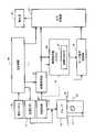
図1には、実施形態に係る超音波診断装置の構成がブロック図として示されている。超音波診断装置は、病院等の医療機関に設置され、生体(被検者)に対する超音波の送受波により得られた受信信号に基づいて、超音波画像を形成する医療用の装置である。超音波診断対象となる臓器は、例えば、乳房である。(2) Details of Embodiment FIG. 1 shows a block diagram of the configuration of an ultrasonic diagnostic apparatus according to an embodiment. 2. Description of the Related Art An ultrasonic diagnostic apparatus is a medical apparatus that is installed in a medical institution such as a hospital and forms an ultrasonic image based on a received signal obtained by transmitting and receiving ultrasonic waves to and from a living body (subject). An organ to be subjected to ultrasonic diagnosis is, for example, a breast.
乳房の集団健診においては、短時間にしかも見落としなく病変部を特定する必要がある。実施形態に係る超音波診断装置は、検査者による病変部の特定を支援するために、超音波画像に含まれる病変部候補(例えば腫瘤である可能性が認められる低輝度部分)を自動的に検出するCADe機能を備えている。これについては後に詳述する。 In mass breast examinations, it is necessary to identify lesions in a short period of time without overlooking them. The ultrasonic diagnostic apparatus according to the embodiment automatically detects a lesion candidate (for example, a low-brightness part that may be a tumor) included in an ultrasound image in order to assist the examiner in identifying the lesion. It has a CADe function to detect. This will be detailed later.
プローブ10は、超音波を送受波する手段として機能するものである。具体的には、プローブ10は、可搬型送受波器であり、それはユーザーである検査者(医師、検査技師等)によって保持及び操作される。乳房の超音波診断に際しては、プローブ10の送受波面(具体的には音響レンズ表面)が被検者の胸部表面に当接される。リアルタイムで表示される断層画像を観察しながら、胸部表面に沿ってプローブ10がマニュアルで走査される。断層画像上において病変部候補が特定された場合、プローブ10の位置及び姿勢がゆっくり調整され、その後、プローブ10の位置及び姿勢を固定したまま、断層画像がじっくり観察される。 The
プローブ10は、図示された構成例において、一次元配列された複数の振動素子からなる振動素子アレイを備えている。振動素子アレイによって超音波ビーム(送信ビーム及び受信ビーム)12が形成され、超音波ビーム12の電子的な走査により走査面14が形成される。走査面14は観察面であり、すなわち二次元データ取込領域である。超音波ビーム12の電子走査方式として、電子セクタ走査方式、電子リニア走査方式等が知られている。超音波ビーム12のコンベックス走査が行われてもよい。プローブ10内に2D振動素子アレイを設け、超音波ビームの二次元走査により、生体内からボリュームデータが取得されてもよい。 The
プローブ10の位置情報を求める測位システムを設けてもよい。測位システムは、例えば、磁気センサ及び磁場発生器により構成される。プローブ(正確にはプローブヘッド)に磁気センサが装着される。磁気センサによって磁場発生器により生成された磁場が検出される。これにより、磁気センサの三次元座標情報が得られる。三次元座標情報に基づいてプローブ10の位置及び姿勢を特定し得る。測位システムから出力された情報に基づいてプローブ10の運動情報を求め、その運動情報を後述するマーク表示制御で利用してもよい。 A positioning system may be provided to determine the location of
送信回路22は送信ビームフォーマーとして機能する。具体的には、送信時において、送信回路22は、振動素子アレイに対して複数の送信信号を並列的に供給する。これにより送信ビームが形成される。受信時において、生体内からの反射波が振動素子アレイに到達すると、複数の振動素子から複数の受信信号が並列的に出力される。受信回路24は受信ビームフォーマーとして機能し、複数の受信信号の整相加算(遅延加算ともいう。)により、ビームデータを生成する。 The transmit
1回の電子走査当たり、電子走査方向に並ぶ複数のビームデータが生成され、それらが走査面14に対応する受信フレームデータを構成する。個々のビームデータは深さ方向に並ぶ複数のエコーデータにより構成される。受信回路24の後段にはビームデータ処理部が設けられているが、その図示が省略されている。 A plurality of beam data arranged in the electronic scanning direction are generated per one electronic scanning, and they constitute reception frame data corresponding to the
画像形成部26は、受信フレームデータに基づいて断層画像(Bモード断層画像)を生成する電子回路である。それはDSC(Digital Scan Converter)を有している。DSCは、座標変換機能、画素補間機能、フレームレート変換機能等を有している。より詳しくは、画像形成部26により、受信フレームデータ列に基づいて表示フレームデータ列が生成される。表示フレームデータ列を構成する各表示フレームデータは、断層画像データである。複数の断層画像データによりリアルタイム動画像が構成される。断層画像以外の超音波画像が生成されてもよい。例えば、カラーフローマッピング画像が形成されてもよいし、組織を立体的に表現した三次元画像が形成されてもよい。図示の構成例では、表示フレームデータ列は、表示処理部32及び画像解析部28に送られている。 The
画像解析部28は、CADe機能を発揮するモジュールである。画像解析部28は、フレームデータごとに、つまり断層画像ごとに、病変部候補を検出する処理を実行する。具体的には、断層画像に対する、二値化処理、エッジ検出等により、低輝度の閉領域として病変部候補が検出される。病変部候補が検出された場合、画像解析部28から病変部候補情報が出力される。 The
病変部候補情報には、病変部候補の位置情報、及び、病変部候補のサイズ情報が含まれる。病変部候補情報には、更に、信頼度が含まれる。信頼度は、病変部候補が実際に病変部である可能性を示す数値である。図1においては、信頼度を演算する信頼度演算部29が示されている。病変部候補情報に、病変部候補の属性(病名、病態、悪性度、)が含まれてもよい。 The lesion candidate information includes location information of the lesion candidate and size information of the lesion candidate. The lesion candidate information further includes reliability. The reliability is a numerical value indicating the possibility that the lesion candidate is actually the lesion. FIG. 1 shows a
病変部候補の位置情報は、例えば、病変部候補それ自体の中心点の座標を示す情報であり、あるいは、病変部候補に接しつつそれを囲む図形の中心点の座標を示す情報である。中心点は代表点である。中心点として、図形の幾何学的な中心点や図形の重心点を採用し得る。病変部候補のサイズ情報は、例えば、病変部候補それ自体のサイズを示す情報であり、あるいは、病変部候補に接しつつそれを囲む図形のサイズを示す情報である。例えば、図形の中心点の座標と図形の左上隅点の座標から、病変部候補のサイズが特定される。中心点の座標が特定されている前提の下、左上隅点の座標を病変部候補のサイズ情報とみなしてもよい。病変部候補のサイズ情報として、病変部候補の面積が求められてもよい。複数の病変部候補が並列的に検出されてもよい。 The positional information of the lesion candidate is, for example, information indicating the coordinates of the central point of the lesion candidate itself, or information indicating the coordinates of the central point of a graphic surrounding and in contact with the lesion candidate. The center point is the representative point. As the center point, the geometric center point of the figure or the center of gravity of the figure can be adopted. The size information of the lesion candidate is, for example, information indicating the size of the lesion candidate itself, or information indicating the size of a graphic surrounding the lesion candidate while being in contact with it. For example, the size of the lesion candidate is identified from the coordinates of the center point of the graphic and the coordinates of the upper left corner point of the graphic. Under the premise that the coordinates of the center point are specified, the coordinates of the upper left corner point may be regarded as the size information of the lesion candidate. As the size information of the lesion candidate, the area of the lesion candidate may be obtained. Multiple lesion candidates may be detected in parallel.
マーク表示制御部30は、検出された病変部候補を通知するマークを超音波画像上に重畳表示するものである。マーク表示制御部30は、信頼度が所定の閾値よりも大きい場合に病変部候補が検出されたとみなし、病変部候補を囲むマークを生成する。マーク表示制御部30は、信頼度の大小をマークの形態の段階的な変化によって表現する。但し、検出開始から一定期間(検出初期)は形態不変期間とされており、形態不変期間内ではマークの形態が初期形態に固定される。形態不変期間の経過後においては信頼度に応じてマークの形態が変更される。マークの形態の変更として、線の太さの変更、線の色の変更、線の透明度の変更、線種の変更、マークの形状の変更、等が挙げられる。 The mark
初期形態は、その後に表示される強調形態群に比べて、目立たないものであり、つまり控えめなものである。逆に言えば、強調形態群は、初期形態に比べて、識別性又は顕現性の高いものであり、つまり目立つものである。 The initial form is unobtrusive or understated compared to the subsequently displayed enhanced forms. Conversely, the emphasized morphology group is more distinguishable or conspicuous than the initial morphology, that is, it stands out.
形態変更について幾つかの具体例をあげておく。信頼度が低い場合に寒色系の色でマークを表示し、信頼度が高い場合に暖色系の色でマークを表示してもよい。信頼度が低い場合に低輝度でマークを表示し、信頼度が高い場合に高輝度でマークを表示してもよい。信頼度が低い場合に高い透明度でマークを表示し、信頼度が高い場合に低い透明度でマークを表示してもよい。信頼度が低い場合に細い線幅でマークを表示し、信頼度が高い場合に太い線幅でマークを表示してもよい。信頼度が低い場合に破線でマークを表示し、信頼度が高い場合に実線でマークを表示してもよい。マーク自体の種類を切り替えてもよい。例えば、4つの角を示す4つの表示要素の表示と矩形の図形の表示とを切り替えてもよい。幾つかの手法を同時に適用してもよい。 Here are some specific examples of the form change. If the reliability is low, the mark may be displayed in a cool color, and if the reliability is high, the mark may be displayed in a warm color. If the reliability is low, the mark may be displayed with low brightness, and if the reliability is high, the mark may be displayed with high brightness. If the confidence is low, the mark may be displayed with high transparency, and if the confidence is high, the mark may be displayed with low transparency. A mark with a thin line width may be displayed when the reliability is low, and a mark with a thick line width may be displayed when the reliability is high. If the reliability is low, the mark may be displayed with a dashed line, and if the reliability is high, the mark may be displayed with a solid line. The type of mark itself may be switched. For example, the display of four display elements indicating four corners and the display of a rectangular figure may be switched. Several techniques may be applied simultaneously.
検出初期においては、病変部候補の検出が不安定であり、信頼度も不安定である。検出初期にけるマーク形態の変化を制限することにより、マーク表示の応答性を良好にしつつも、検出初期においてマークが必要以上に目立って目障りとなることを防止できる。 In the initial stage of detection, the detection of lesion candidates is unstable, and the reliability is also unstable. By limiting the change in the form of the mark at the initial stage of detection, it is possible to improve the responsiveness of the mark display and prevent the mark from becoming unnecessarily conspicuous and an eyesore at the initial stage of detection.
画像形成部26、画像解析部28及びマーク表示制御部30は、それぞれ、プロセッサにより構成され得る。単一のプロセッサが、画像形成部26、画像解析部28及びマーク表示制御部30として機能してもよい。後述するCPUが、画像形成部26、画像解析部28及びマーク表示制御部30として機能してもよい。 The
表示処理部32は、グラフィック画像生成機能、カラー演算機能、画像合成機能等を有する。表示処理部32には、画像形成部26の出力及びマーク表示制御部30の出力が与えられている。病変部候補を囲むマークは、グラフィック画像を構成する1つの要素である。実施形態においては、マーク表示制御部30がマークを生成しているが、主制御部38、表示処理部32、等がマークを生成するようにしてもよい。 The
表示器36は、LCD、有機EL表示デバイス等によって構成される。表示器36には、動画像としての断層画像がリアルタイムで表示され、また、グラフィック画像の一部としてマークが表示される。表示処理部32は、例えば、プロセッサにより構成される。 The
主制御部38は、図1に示された各構成要素の動作を制御するものである。主制御部38は、実施形態において、プログラムを実行するCPUによって構成される。主制御部38には、操作パネル40が接続されている。操作パネル40は入力デバイスであり、それは、複数のスイッチ、複数のボタン、トラックボール、キーボード等を有する。 The
操作パネル40を利用してマーク表示条件を設定又は変更し得る。マーク表示条件には、形態固定期間、複数の閾値、等が含まれる。例えば、プローブ10の移動速度、フレームデータの安定度、信頼度のばらつき、等に基づいて、形態固定期間が適応的に定められてもよい。 The
実施形態においては、表示フレームデータ列が画像解析部28に与えられているが、受信フレームデータ列が画像解析部28に与えられてもよい(符号42を参照)。その場合、画像形成部26とは別に、画像形成を簡易且つ迅速に実行する他の画像形成部が設けられる。 In the embodiment, the display frame data string is given to the
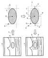
図2には、マーク生成方法が示されている。断層画像44には病変部候補46が含まれる。断層画像44の二値化47により二値化画像が生成される。二値化画像に対するエッジ検出又は領域検出により、二値化された病変部候補46Aが抽出される。例えば、病変部候補46Aにおける水平方向の両端座標、及び、病変部候補46Aにおける垂直方向の両端座標により、病変部候補46Aに外接する矩形52が定義される。実際には、矩形52の中心点48の座標及び矩形の左上隅点50の座標が特定される。 FIG. 2 shows the mark generation method. A
矩形52の外側に、水平方向及び垂直方向に一定のマージン56,58をおいた図形として、矩形54が定義される。その矩形54が断層画像44上にマーク64として表示される。マーク64は、病変部候補46及びその周囲を囲む図形である。図示の例では、マーク64は、破線で構成されている。4つの隅部分のみを表す4つの要素からなるマークが表示されてもよい。円形や楕円のマークが表示されてもよい。 A
実施形態においては、フレームデータ単位で病変部候補46の検出が実行される。病変部候補46が検出された場合に、それを含むフレームデータに対応する断層画像44上にマーク64が表示される。マーク64の表示により、検査者に対して病変部候補46の存在を知覚させることが可能となり、病変部候補46の見落としを防止できる。 In the embodiment, the
病変部候補46の検出が連続している連続検出状態において、病変部候補の検出開始時点から形態不変期間が経過するまで、マーク64の形態が固定され、形態不変期間の経過後に、信頼度に応じてマーク64の形態が変更される。つまり、マーク64の形態により信頼度の大小が表現される。病変部候補46が検出されなくなった時点で、マーク64が消去される。実際には、信頼度が後述する第1閾値と比較されており、第1閾値よりも信頼度が低い場合には病変部候補が非検出であるとみなされ、第1閾値よりも信頼度が高い場合には病変部候補が検出されたとみなされる。病変部候補46の検出が1又は数フレーム途絶えた場合、病変部候補46の検出が連続しているとみなしてもよい。 In the continuous detection state in which the
図3には、図1に示したマーク表示制御部の動作がフローチャートとして示されている。S10では、病変部候補が検出されたか否かが判定される。上記のように、フレームデータごとに病変部候補の有無が検査され、また、フレームデータごとに信頼度が参照される。なお、図示の例では、S10においてマーク表示終了も判定される。 FIG. 3 shows the operation of the mark display control section shown in FIG. 1 as a flow chart. In S10, it is determined whether or not a lesion candidate has been detected. As described above, the presence or absence of lesion candidates is checked for each frame data, and the reliability is referred to for each frame data. In the illustrated example, the end of mark display is also determined in S10.
S12では、マーク表示が開始される。マークの形態として初期形態が選択される。S14において、マークが最初に検出された時点から形態不変期間を経過しているか否かが判定される。S16では、病変部候補の検出が現時点でも連続しているか否かが判定される。病変部候補の検出が連続している場合、つまり連続検出状態が判定された場合、S14が繰り返し実行される。その過程で、形態不変期間が経過した時点で、S18が実行される。S16において病変部候補の検出が途絶えたと判定された場合、つまり連続検出状態が終了した場合、S17でマークが消去された上で、S10以降の各工程が実行される。なお、図示の例では、S16においてマーク表示終了も判定される。 In S12, mark display is started. An initial shape is selected as the shape of the mark. In S14, it is determined whether or not the morphology invariant period has elapsed since the mark was first detected. In S16, it is determined whether or not detection of lesion candidates continues at the present time. If lesion candidates are continuously detected, that is, if a continuous detection state is determined, S14 is repeatedly executed. In the process, S18 is executed when the form invariant period has passed. If it is determined in S16 that the detection of lesion candidates has ceased, that is, if the continuous detection state has ended, the mark is erased in S17, and then the steps from S10 onward are executed. In the illustrated example, the end of mark display is also determined in S16.
S18では、信頼度に従ってマークの形態が変更される。後述する第1例では、信頼度軸上に定められるマーク表示範囲が3つの区間に分割されており、3つの区間に対して3つのマーク形態が割り当てられている。S18では、信頼度の大きさに従って3つの形態の中から特定の形態が選択され、その形態を有するマークが表示される。3つの形態には、最下位区分に対応する形態としての初期形態が含まれる。形態不変期間の経過直後において信頼度が最下位区分に属する場合、結果として、マークの形態が維持されることになる。これによりマーク形態の変更の頻度を低減して、信頼度情報の提供と画像観察の便宜とを両立させることが可能となる。 At S18, the form of the mark is changed according to the reliability. In the first example described later, the mark display range defined on the reliability axis is divided into three sections, and three mark forms are assigned to the three sections. At S18, a specific form is selected from among the three forms according to the degree of reliability, and a mark having that form is displayed. The three forms include the initial form as the form corresponding to the lowest partition. If the reliability belongs to the lowest category immediately after the morphology invariant period has elapsed, the result is that the morphology of the mark is preserved. As a result, the frequency of changing the mark form can be reduced, and both the provision of reliability information and the convenience of image observation can be achieved.
S20では、上記S16と同様、病変部候補の検出が連続しているか否かが判定される。病変部候補の検出が連続している場合、つまり連続検出状態においては、S18が繰り返し実行される。S20において病変部候補の検出が途絶えたと判定された場合、つまり連続検出状態が終了した場合、S17でマークが消去された上で、S10以降の各工程が実行される。なお、図示の例では、S20においてマーク表示終了も判定される。 In S20, similarly to S16 above, it is determined whether or not lesion candidates are continuously detected. When lesion candidates are continuously detected, that is, in a continuous detection state, S18 is repeatedly executed. If it is determined in S20 that the detection of lesion candidates has ceased, that is, if the continuous detection state has ended, the mark is erased in S17, and then the steps from S10 onward are executed. In the illustrated example, the end of mark display is also determined in S20.
図4には、マーク表示制御の第1例が示されている。図4の下部には、信頼度Rの大小を表す信頼度軸が示されている。信頼度軸上には、マーク表示範囲200及びそれ以下のマーク非表示範囲202が定められている。マーク表示範囲200の下限は第1閾値th1で規定される。マーク表示範囲200は、低区間200A、中区間200B、高区間200Cに分割されている。低区間200Aが最下位区間である。なお、信頼度は0から100の間の数値をとる。あるタイミングtでの信頼度がRtと表現されている。 FIG. 4 shows a first example of mark display control. At the bottom of FIG. 4, a reliability axis indicating the magnitude of the reliability R is shown. A
検出初期(符号72を参照)においては、形態(初期形態)Aをもったマークが表示される。検出初期は形態不変期間に相当し、その期間内においては信頼度Rtの大きさにかかわらず形態Aをもったマークが表示される。検出初期後つまり形態不変期間の経過後においては(符号74を参照)、符号76,78,80で示されているように、形態A,形態B及び形態Cの内で、信頼度Rtが属する区間に対応する形態が選択され、その形態をもったマークが表示される。 At the beginning of detection (see reference numeral 72), a mark with morphology (initial morphology) A is displayed. The initial stage of detection corresponds to a morphological invariant period, during which a mark having morphology A is displayed regardless of the magnitude of the reliability Rt. After the initial stage of detection, that is, after the morphology invariant period has elapsed (see reference numeral 74), as indicated by
形態Aは上述した初期形態である。各形態の顕現性又は顕著性(つまり目立つ度合い)を不等号で表現すると、形態A<形態B<形態Cの関係が成立している。形態Aは信頼度Rtが第1閾値th1以上且つ第2閾値th2未満の場合に選択される。形態Bは信頼度Rtが第2閾値th2以上且つ第3閾値th3未満の場合に選択される。形態Cは信頼度Rtが第3閾値th3以上の場合に選択される。th1は例えば60であり、th2は例えば75であり、th3は例えば90である。 Form A is the initial form described above. Expressing the conspicuity or conspicuity (that is, the degree of conspicuousness) of each form with an inequality sign, the relationship of form A<form B<form C is established. Mode A is selected when the reliability Rt is greater than or equal to the first threshold th1 and less than the second threshold th2. Mode B is selected when the reliability Rt is greater than or equal to the second threshold th2 and less than the third threshold th3. Mode C is selected when the reliability Rt is greater than or equal to the third threshold th3. th1 is, for example, 60, th2 is, for example, 75, and th3 is, for example, 90.
以上のように、病変部候補の検出が連続している連続検出状態においては、病変部候補の検出開始から一定の期間が経過するまで、信頼度が変化してもマークの形態は変化しない。その期間においては信頼度が不安定であることも多く、信頼度に応じてマークの形態を変化させると、マークが超音波画像の観察の妨げとなり易い。実施形態によれば、そのような問題が生じることを回避できる。また、実施形態によれば、一定の期間の経過後においては、マークの形態の変化を通じて信頼度の変化を把握又は認識することが可能となる。これにより、信頼度を考慮しつつ、マークによって通知された病変部候補を精査することが可能となる。一定の期間の経過後においては通常、プローブの動きはゆっくりとなり又はプローブが事実上静止した状態となるので、マークの形態が激しく変化することもない。 As described above, in the continuous detection state in which lesion candidates are continuously detected, the form of the mark does not change even if the reliability changes until a certain period of time has elapsed since the detection of the lesion candidate began. During that period, the reliability is often unstable, and if the form of the mark is changed according to the reliability, the mark tends to interfere with the observation of the ultrasonic image. According to the embodiment, such problems can be avoided. Further, according to the embodiment, after a certain period of time has passed, it is possible to grasp or recognize the change in reliability through the change in the shape of the mark. As a result, it is possible to closely examine the lesion candidate notified by the mark while taking into consideration the degree of reliability. After a certain period of time, the movement of the probe usually slows down or the probe is virtually stationary, so that the morphology of the mark does not change drastically.
図5を用いて、図4に示した第1例をより詳しく説明する。符号82は信頼度の時間変化を表すグラフを示している。横軸は時間軸であり、縦軸は信頼度軸である。信頼度軸上に第1閾値th1、第2閾値th2及び第3閾値th3が設定されており、それによって3つの区間が設定されている。符号84は、各時刻で表示されるマークを示している。 The first example shown in FIG. 4 will be described in more detail with reference to FIG. A
時刻t1において、信頼度Rtが第1閾値th1を超えており、これにより初期形態Aを有するマークが表示されている。時刻t2では信頼度Rtが第1閾値th1を下回っている。時刻t1から時刻t2までの期間は形態不変期間86に達していない。 At time t1, the reliability Rt exceeds the first threshold th1, and thus the mark having the initial form A is displayed. At time t2, the reliability Rt is below the first threshold th1. The period from time t1 to time t2 has not reached the morphological
時刻t3において、信頼度Rtが再び第1閾値th1を超えており、更に、第2閾値th2も超えている。その場合、初期形態Aを有するマークが表示される。時刻t4において、形態不変期間88を経過しており、時刻t4以降からマーク形態の変化が許容される。形態不変期間88として数秒が定められてもよい。 At time t3, the reliability Rt again exceeds the first threshold th1 and also exceeds the second threshold th2. In that case, a mark with initial form A is displayed. At time t4, the shape
時刻t4においては、信頼度Rtは第1区間に属しており、初期形態Aが維持されている。その後、時刻t5におおいて信頼度Rtが第2閾値を超えており、時刻t5では形態Bを有するマークに変更される。更に、時刻t6では、信頼度Rtが第3閾値を超えており、形態Cを有するマークに変更される。その後、時刻t7で信頼度Rtが第1区間に復帰しており、その時点で初期形態Aを有するマークに変更される。時刻t8では、信頼度Rtが第1閾値を下回っており、その時点でマークが消去される。 At time t4, the reliability Rt belongs to the first interval, and the initial form A is maintained. After that, the reliability Rt exceeds the second threshold at time t5, and the mark is changed to form B at time t5. Further, at time t6, the reliability Rt exceeds the third threshold, and the mark is changed to have the form C. After that, at time t7, the reliability Rt returns to the first interval, and the mark is changed to the initial form A at that time. At time t8, the reliability Rt is below the first threshold, and the mark is erased at that point.
その後、時刻t9において、信頼度Rtが第1閾値th1を超えており、実際には第3閾値th3に達しているが、その時点で表示されるものは初期形態Aを有するマークである。時刻t10では、信頼度Rtが第1閾値th1を下回っている。マークは瞬時的に又は短期間のみ表示されたことになる。時刻t11では再び信頼度Rtが第1閾値を超えており、時刻t12において、形態不変期間が経過し、マークの形態の変化が許容されている。 After that, at time t9, the reliability Rt exceeds the first threshold th1 and actually reaches the third threshold th3, but the mark having the initial form A is displayed at that time. At time t10, the reliability Rt is below the first threshold th1. The mark would have been displayed momentarily or only for a short period of time. At time t11, the reliability Rt exceeds the first threshold value again, and at time t12, the morphological invariant period has passed, and changes in the morphology of the mark are permitted.
ユーザーにより形態不変期間が指定されてもよいし、状況に応じて形態不変期間が適応的に自動設定されてもよい。例えば、フレームデータの安定度、フレーム全体の信頼度分布の変化率、等に基づいて形態不変期間が定められてもよい。 The user may specify the morphological invariant period, or the morphological invariant period may be adaptively and automatically set according to the situation. For example, the shape invariant period may be determined based on the stability of frame data, the rate of change in the reliability distribution of the entire frame, and the like.
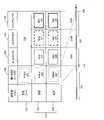
図6には、マーク表示制御の第2例が示されている。マークがとり得る形態92~98の内で、形態92が初期形態であり、他の3つの形態94,96,98がそれぞれ信頼度表現形態である。形態不変期間の経過後、信頼度が第1区間に属する場合に形態94が選択され、信頼度が第2区間に属する場合に形態96が選択され、信頼度が第3区間に属する場合に形態98が選択される。初期形態92には、矩形のマーク本体100が含まれる。エリア102にはバーグラフは含まれない。 FIG. 6 shows a second example of mark display control. Of the forms 92-98 that the mark can take,
形態94,96,98は、それぞれ、矩形のマーク本体100を有し、また、バーグラフ102A,102B,102Cを有する。バーグラフ102A,102B,102Cにおけるバーの長さ(水平方向の大きさ)が信頼度の大きさを表している。第2例によれば、形態不変期間の経過後に表示されるマークの形態を観察することにより、信頼度を直感的に認識することが可能である。バーグラフ102A,102B,102Cの表示に当たっては、それが超音波画像を完全に隠さないように、それを半透明で表示してもよい。
図7には、図1に示した一部の構成の変形例が示されている。画像解析部28Aは、信頼度演算部29Aの他、評価部104を有している。評価部104は、図示の例では、腫瘍の属性として3つのクラスを識別する機能を備えている。具体的には、嚢胞に相当する良性腫瘍1、それ以外の良性腫瘍2、及び、悪性腫瘍を識別する機能を備えている。それらの内で、例えば、良性腫瘍が非重要属性とされ、良性腫瘍2及び悪性腫瘍が重要属性とされる。 FIG. 7 shows a modification of part of the configuration shown in FIG. The
マーク表示制御部30Aは、候補検出状況において、検出開始から形態不変期間が経過するまで、マークの形態として初期形態を選択し、その後においては、良性腫瘍1についてはマークを非表示にし、良性腫瘍2及び悪性腫瘍については信頼度に応じてマークの形態を変更する。すなわち、非重要属性を有する病変部候補については、マークを短時間表示してその存在を検査者に通知した上で、表示内容簡素化の観点からマークを消去するものである。重要属性を有する病変部候補については、図3等に示した手順に従ってマーク表示制御が実行される。 In the candidate detection situation, the mark
図8には、マーク表示制御の第3例が示されている。これは図7に示した構成を前提とするものである。なお、図8において、図4に示した要素と同様の要素には同一符号を付しその説明を省略する。 FIG. 8 shows a third example of mark display control. This assumes the configuration shown in FIG. In FIG. 8, elements similar to those shown in FIG. 4 are denoted by the same reference numerals, and descriptions thereof are omitted.
図8において、検出初期(形態不変期間)106においては、マークの形態として、属性(クラス)にかかわらず初期形態120が選択される。初期検出期間後においては、良性腫瘍116及び悪性腫瘍118についてはマークの形態が変更されるが、良性腫瘍114についてはマークが消去される(符号134を参照)。符号115は重要属性を示しており、それは腫瘍116及び悪性腫瘍118に相当する。良性腫瘍114は非重要属性に相当する。重要属性115については、検出初期の経過後、信頼度Rtに応じてマークの形態が変更される。 In FIG. 8, in the initial stage of detection (morphological invariant period) 106, an
具体的には、図示の例において、良性腫瘍116については青色を有するマークが表示され、その形態(線種)が信頼度Rtに応じて符号122,124,126で示すように変更される。悪性腫瘍118については赤色を有するマークが表示され、その形態(線種)が信頼度Rtに応じて符号128,130,132で示すように変更される。信頼度Rtが高くなるに従って、より目立つようにマークの形態が段階的に選択される。なお、図8に示した第3例では、最下位区間に対応する形態122,128は初期形態120に一致していない。一方、属性の違いによらず初期形態120は同一である。 Specifically, in the illustrated example, a blue mark is displayed for the
実施形態において、超音波画像上に複数の病変部候補が含まれる場合、病変部候補ごとに上記のマーク表示制御が実行される。画像解析部は機械学習型解析器で構成され得る。それは例えばCNNで構成される。 In the embodiment, when a plurality of lesion candidates are included on an ultrasound image, the above mark display control is performed for each lesion candidate. The image analysis unit can be configured with a machine learning type analyzer. It consists of, for example, a CNN.
10 プローブ、26 画像形成部、28 画像解析部、29 信頼度演算部、30 マーク表示制御部、32 表示処理部。
10 probe, 26 image formation unit, 28 image analysis unit, 29 reliability calculation unit, 30 mark display control unit, 32 display processing unit.
Claims (8)
Translated fromJapanese前記フレームデータ列に基づいて形成された超音波画像上に前記病変部候補を通知するマークを表示する表示制御部であって、前記病変部候補の検出が連続している連続検出状態において前記マークを継続的に表示する表示制御部と、
を含み、
前記表示制御部は、前記連続検出状態において、前記病変部候補が最初に検出された時点から形態不変期間を経過するまで前記マークの形態を固定すると共に前記形態不変期間の経過後に前記信頼度に応じて前記マークの形態を変更する、
ことを特徴とする超音波診断装置。a computing unit that receives a frame data string obtained by repeating scanning of an ultrasonic beam and computes a reliability indicating the possibility that a lesion candidate included in the frame data is a lesion for each frame data;
A display control unit for displaying a mark for notifying the lesion candidate on the ultrasonic image formed based on the frame data string, wherein the mark is displayed in a continuous detection state in which the lesion candidate is continuously detected. a display control unit that continuously displays the
including
In the continuous detection state, the display control unit fixes the shape of the mark from when the lesion candidate is first detected until a shape constant period elapses, and after the shape constant period elapses, sets the reliability to the mark. changing the form of the mark accordingly;
An ultrasonic diagnostic apparatus characterized by:
前記表示制御部は、前記連続検出状態において、前記形態不変期間の経過後に前記信頼度が高くなるに従って前記マークの形態を段階的に変更する、
ことを特徴とする超音波診断装置。The ultrasonic diagnostic apparatus according to claim 1,
In the continuous detection state, the display control unit changes the form of the mark step by step as the reliability increases after the form invariant period elapses.
An ultrasonic diagnostic apparatus characterized by:
信頼度軸上に非表示範囲及び表示範囲が定められ、
前記表示範囲は最下位区間を含む複数の区間に分けられ、
前記形態不変期間において前記マークの形態は初期形態であり、
前記形態不変期間の経過後において前記マークの形態は前記複数の区間に対応する複数の形態の中のいずれかであり、
前記複数の形態には前記最下位区間に対応する前記初期形態が含まれる、
ことを特徴とする超音波診断装置。In the ultrasonic diagnostic apparatus according to claim 2,
A non-display range and a display range are defined on the reliability axis,
The display range is divided into a plurality of sections including the lowest section,
the form of the mark is the initial form in the form-invariant period;
After the morphology unchanged period has elapsed, the morphology of the mark is any one of a plurality of morphologies corresponding to the plurality of sections,
wherein the plurality of morphologies includes the initial morphology corresponding to the lowest interval;
An ultrasonic diagnostic apparatus characterized by:
前記マークの形態の段階的な変更には、前記マークの太さの段階的な変更、前記マークの色の段階的な変更、前記マークの透明度の段階的な変更、及び、前記マークを構成する線の種類の段階的な変更、の内の少なくとも1つが含まれる、
ことを特徴とする超音波診断装置。In the ultrasonic diagnostic apparatus according to claim 2,
The gradual change of the shape of the mark includes gradual change of the thickness of the mark, gradual change of the color of the mark, gradual change of the transparency of the mark, and gradual change of the mark. a gradual change in line type, including at least one of
An ultrasonic diagnostic apparatus characterized by:
前記表示制御部は、前記信頼度が閾値よりも大きくなった場合に前記マークを表示し、前記信頼度が前記閾値よりも小さくなった場合に前記マークを消去し、
前記形態不変期間の経過前に前記信頼度が前記閾値よりも小さくなった場合に、前記超音波画像上の前記マークが消去される、
ことを特徴とする超音波診断装置。The ultrasonic diagnostic apparatus according to claim 1,
The display control unit displays the mark when the reliability is greater than a threshold, and erases the mark when the reliability is less than the threshold;
The mark on the ultrasonic image is erased when the reliability becomes smaller than the threshold value before the morphology invariant period elapses.
An ultrasonic diagnostic apparatus characterized by:
前記演算部は、前記フレームデータごとに、当該フレームデータに含まれる病変部候補の属性を判定し、
前記表示制御部は、前記連続検出状態において、前記形態不変期間の経過後に、前記信頼度及び前記属性の組み合わせに応じて前記マークの形態を変更する、
ことを特徴とする超音波診断装置。The ultrasonic diagnostic apparatus according to claim 1,
The computing unit determines, for each frame data, an attribute of a lesion candidate included in the frame data,
In the continuous detection state, the display control unit changes the form of the mark according to the combination of the reliability and the attribute after the form invariant period has elapsed.
An ultrasonic diagnostic apparatus characterized by:
前記演算部は、前記フレームデータごとに、当該フレームデータに含まれる病変部候補の属性として重要属性及び非重要属性のいずれかを判定し、
前記表示制御部は、前記重要属性が判定された場合に、前記連続検出状態において、前記形態不変期間の経過後に、前記信頼度に応じて前記マークの形態を変更し、
前記表示制御部は、前記非重要属性が判定された場合に、前記連続検出状態において、前記形態不変期間の経過後に、前記マークを消去する、
ことを特徴とする超音波診断装置。The ultrasonic diagnostic apparatus according to claim 1,
The calculation unit determines, for each frame data, whether an attribute of a candidate lesion included in the frame data is an important attribute or a non-important attribute,
When the important attribute is determined, the display control unit changes the form of the mark according to the reliability after the form unchanged period has elapsed in the continuous detection state,
When the non-important attribute is determined, the display control unit erases the mark after the morphological invariant period has elapsed in the continuous detection state.
An ultrasonic diagnostic apparatus characterized by:
前記フレームデータ列に基づいて形成された超音波画像上に前記病変部候補を通知するマークを表示する工程と、
を含み、
前記病変部候補の検出が連続している連続検出状態において前記マークが継続的に表示され、
前記マークの継続的な表示に際して、前記病変部候補が最初に検出された時点から形態不変期間を経過するまで前記マークの形態が固定され、その後、前記信頼度に応じて前記マークの形態が変更される、
ことを特徴とする診断支援方法。
a step of calculating a reliability indicating the possibility that a lesion candidate included in the frame data is a lesion for each frame data constituting a frame data string obtained by repeating scanning with an ultrasonic beam;
displaying a mark for notifying the lesion candidate on the ultrasonic image formed based on the frame data sequence;
including
the mark is continuously displayed in a continuous detection state in which the detection of the lesion candidate is continuous;
When the mark is continuously displayed, the shape of the mark is fixed from the time when the lesion candidate is first detected until a shape invariant period elapses, and then the shape of the mark is changed according to the reliability. to be
A diagnosis support method characterized by:
Priority Applications (3)
| Application Number | Priority Date | Filing Date | Title |
|---|---|---|---|
| JP2021080736AJP7488789B2 (en) | 2021-05-12 | 2021-05-12 | Ultrasound diagnostic device and diagnostic support method |
| US17/726,628US20220361852A1 (en) | 2021-05-12 | 2022-04-22 | Ultrasonic diagnostic apparatus and diagnosis assisting method |
| CN202210436211.4ACN115337038A (en) | 2021-05-12 | 2022-04-24 | Ultrasonic diagnostic apparatus and diagnostic support method |
Applications Claiming Priority (1)
| Application Number | Priority Date | Filing Date | Title |
|---|---|---|---|
| JP2021080736AJP7488789B2 (en) | 2021-05-12 | 2021-05-12 | Ultrasound diagnostic device and diagnostic support method |
Publications (2)
| Publication Number | Publication Date |
|---|---|
| JP2022174781Atrue JP2022174781A (en) | 2022-11-25 |
| JP7488789B2 JP7488789B2 (en) | 2024-05-22 |
Family
ID=83948008
Family Applications (1)
| Application Number | Title | Priority Date | Filing Date |
|---|---|---|---|
| JP2021080736AActiveJP7488789B2 (en) | 2021-05-12 | 2021-05-12 | Ultrasound diagnostic device and diagnostic support method |
Country Status (3)
| Country | Link |
|---|---|
| US (1) | US20220361852A1 (en) |
| JP (1) | JP7488789B2 (en) |
| CN (1) | CN115337038A (en) |
Families Citing this family (1)
| Publication number | Priority date | Publication date | Assignee | Title |
|---|---|---|---|---|
| WO2020206069A1 (en)* | 2019-04-03 | 2020-10-08 | Butterfly Network, Inc. | Methods and apparatuses for guiding collection of ultrasound images |
Citations (3)
| Publication number | Priority date | Publication date | Assignee | Title |
|---|---|---|---|---|
| JP2004159739A (en)* | 2002-11-11 | 2004-06-10 | Ge Medical Systems Global Technology Co Llc | Method and apparatus for image processing |
| WO2011155168A1 (en)* | 2010-06-07 | 2011-12-15 | パナソニック株式会社 | Malignant tissue tumor detection method and malignant tissue tumor detection device |
| WO2017081976A1 (en)* | 2015-11-10 | 2017-05-18 | オリンパス株式会社 | Endoscope device |
Family Cites Families (7)
| Publication number | Priority date | Publication date | Assignee | Title |
|---|---|---|---|---|
| JP5566299B2 (en)* | 2008-10-20 | 2014-08-06 | 株式会社日立メディコ | Medical image processing apparatus and medical image processing method |
| KR20160012758A (en)* | 2014-07-25 | 2016-02-03 | 삼성전자주식회사 | Apparatus and Method for aiding image diagnosis |
| US10140710B2 (en)* | 2017-03-09 | 2018-11-27 | Kevin Augustus Kreeger | Automatic key frame detection |
| WO2018198161A1 (en)* | 2017-04-24 | 2018-11-01 | オリンパス株式会社 | Endoscope image processing apparatus and endoscope image processing method |
| WO2019187049A1 (en)* | 2018-03-30 | 2019-10-03 | オリンパス株式会社 | Diagnosis support device, diagnosis support method, and diagnosis support program |
| US11375984B2 (en)* | 2018-08-31 | 2022-07-05 | Seno Medical Instruments, Inc. | Method and system for managing feature reading and scoring in ultrasound and/or optoacoustic images |
| CN113168699B (en)* | 2019-07-18 | 2023-07-25 | Hoya株式会社 | Computer program, information processing method, and endoscope processor |
- 2021
- 2021-05-12JPJP2021080736Apatent/JP7488789B2/enactiveActive
- 2022
- 2022-04-22USUS17/726,628patent/US20220361852A1/ennot_activeAbandoned
- 2022-04-24CNCN202210436211.4Apatent/CN115337038A/enactivePending
Patent Citations (3)
| Publication number | Priority date | Publication date | Assignee | Title |
|---|---|---|---|---|
| JP2004159739A (en)* | 2002-11-11 | 2004-06-10 | Ge Medical Systems Global Technology Co Llc | Method and apparatus for image processing |
| WO2011155168A1 (en)* | 2010-06-07 | 2011-12-15 | パナソニック株式会社 | Malignant tissue tumor detection method and malignant tissue tumor detection device |
| WO2017081976A1 (en)* | 2015-11-10 | 2017-05-18 | オリンパス株式会社 | Endoscope device |
Also Published As
| Publication number | Publication date |
|---|---|
| CN115337038A (en) | 2022-11-15 |
| JP7488789B2 (en) | 2024-05-22 |
| US20220361852A1 (en) | 2022-11-17 |
Similar Documents
| Publication | Publication Date | Title |
|---|---|---|
| JP5454844B2 (en) | Ultrasonic diagnostic apparatus, ultrasonic image display apparatus, and ultrasonic image display program | |
| JP5872216B2 (en) | Ultrasonic diagnostic apparatus and ultrasonic image processing apparatus | |
| US11403778B2 (en) | Fetal development monitoring | |
| JP5002181B2 (en) | Ultrasonic diagnostic apparatus and ultrasonic diagnostic apparatus control method | |
| JP2014121594A (en) | Ultrasonic diagnostic apparatus, image processing apparatus, and image processing method | |
| CN110446466B (en) | Volume rendered ultrasound imaging | |
| JP2006187594A (en) | Ultrasonic diagnostic system and its method | |
| JP2023160986A (en) | Ultrasonic diagnostic device and analysis device | |
| JP2020501713A (en) | Fetal ultrasound imaging | |
| JP2022174781A (en) | Ultrasonic diagnostic device and diagnosis support method | |
| US12048588B2 (en) | Ultrasound diagnostic apparatus and diagnosis assistance method | |
| JP7438038B2 (en) | Ultrasonic diagnostic device and diagnostic support method | |
| CN113679415B (en) | Ultrasonic diagnostic apparatus and diagnostic support method | |
| JP7631179B2 (en) | Ultrasound diagnostic device and ultrasound image processing method | |
| EP3456265A1 (en) | Fetal development monitoring | |
| JP2012143356A (en) | Ultrasonic diagnostic equipment and program | |
| JP2013052131A (en) | Ultrasonic diagnostic system and vasoconstriction improvement display program | |
| CN115337039B (en) | Ultrasonic diagnostic device, diagnostic assistance method, and computer program product | |
| US10426444B2 (en) | Ultrasonic diagnosis apparatus, medical image processing apparatus and medical image processing method | |
| CN117547307A (en) | Peristaltic wave detection method and ultrasonic imaging device |
Legal Events
| Date | Code | Title | Description |
|---|---|---|---|
| A711 | Notification of change in applicant | Free format text:JAPANESE INTERMEDIATE CODE: A711 Effective date:20211109 | |
| A621 | Written request for application examination | Free format text:JAPANESE INTERMEDIATE CODE: A621 Effective date:20231027 | |
| A871 | Explanation of circumstances concerning accelerated examination | Free format text:JAPANESE INTERMEDIATE CODE: A871 Effective date:20231027 | |
| A131 | Notification of reasons for refusal | Free format text:JAPANESE INTERMEDIATE CODE: A131 Effective date:20240109 | |
| A521 | Request for written amendment filed | Free format text:JAPANESE INTERMEDIATE CODE: A523 Effective date:20240229 | |
| TRDD | Decision of grant or rejection written | ||
| A01 | Written decision to grant a patent or to grant a registration (utility model) | Free format text:JAPANESE INTERMEDIATE CODE: A01 Effective date:20240416 | |
| A61 | First payment of annual fees (during grant procedure) | Free format text:JAPANESE INTERMEDIATE CODE: A61 Effective date:20240510 | |
| R150 | Certificate of patent or registration of utility model | Ref document number:7488789 Country of ref document:JP Free format text:JAPANESE INTERMEDIATE CODE: R150 | |
| S111 | Request for change of ownership or part of ownership | Free format text:JAPANESE INTERMEDIATE CODE: R313111 | |
| R350 | Written notification of registration of transfer | Free format text:JAPANESE INTERMEDIATE CODE: R350 |