JP2022173852A - Coupling system and check valve - Google Patents
Coupling system and check valveDownload PDFInfo
- Publication number
- JP2022173852A JP2022173852AJP2021079828AJP2021079828AJP2022173852AJP 2022173852 AJP2022173852 AJP 2022173852AJP 2021079828 AJP2021079828 AJP 2021079828AJP 2021079828 AJP2021079828 AJP 2021079828AJP 2022173852 AJP2022173852 AJP 2022173852A
- Authority
- JP
- Japan
- Prior art keywords
- check valve
- female member
- fluid
- male member
- elastic body
- Prior art date
- Legal status (The legal status is an assumption and is not a legal conclusion. Google has not performed a legal analysis and makes no representation as to the accuracy of the status listed.)
- Granted
Links
Images


Classifications
- B—PERFORMING OPERATIONS; TRANSPORTING
- B65—CONVEYING; PACKING; STORING; HANDLING THIN OR FILAMENTARY MATERIAL
- B65D—CONTAINERS FOR STORAGE OR TRANSPORT OF ARTICLES OR MATERIALS, e.g. BAGS, BARRELS, BOTTLES, BOXES, CANS, CARTONS, CRATES, DRUMS, JARS, TANKS, HOPPERS, FORWARDING CONTAINERS; ACCESSORIES, CLOSURES, OR FITTINGS THEREFOR; PACKAGING ELEMENTS; PACKAGES
- B65D25/00—Details of other kinds or types of rigid or semi-rigid containers
- B65D25/38—Devices for discharging contents
- B65D25/40—Nozzles or spouts
- B65D25/42—Integral or attached nozzles or spouts
- F—MECHANICAL ENGINEERING; LIGHTING; HEATING; WEAPONS; BLASTING
- F16—ENGINEERING ELEMENTS AND UNITS; GENERAL MEASURES FOR PRODUCING AND MAINTAINING EFFECTIVE FUNCTIONING OF MACHINES OR INSTALLATIONS; THERMAL INSULATION IN GENERAL
- F16K—VALVES; TAPS; COCKS; ACTUATING-FLOATS; DEVICES FOR VENTING OR AERATING
- F16K15/00—Check valves
- F16K15/18—Check valves with actuating mechanism; Combined check valves and actuated valves
Landscapes
- Engineering & Computer Science (AREA)
- Mechanical Engineering (AREA)
- General Engineering & Computer Science (AREA)
- Check Valves (AREA)
- Details Of Rigid Or Semi-Rigid Containers (AREA)
Abstract
Description
Translated fromJapanese本発明は、包装容器等に流体を充填または吐出する際に用いられる連結システムおよび逆止弁に関するものである。 TECHNICAL FIELD The present invention relates to a connection system and a check valve used when filling or discharging a fluid into a packaging container or the like.
従来、インクなどの液体、複写機のトナーなどの粉体、あるいは何らかの気体などの流体を充填または吐出するための逆止弁の機能を有する様々な連結システムが知られている。このうち、本出願人は、2ピース構成にすることにより着脱が容易でしかも比較的安価なものにできるとともに、流体の漏れが少ない連結システムを提案している(特許文献1参照)。 Various coupling systems are known in the prior art that function as check valves for filling or dispensing fluids such as liquids such as ink, powders such as copier toner, or any gas. Among these, the applicant of the present application has proposed a connection system that has a two-piece structure, which is easy to attach and detach, can be made relatively inexpensive, and has less fluid leakage (see Patent Document 1).
具体的には、この連結システムは、流体が流れる流通路を内部に有する雄部材と、雄部材が挿入される導通路を内部に有する雌部材と、雌部材の前記導通路の開口部に設けられる逆止弁とを備える。そして、この逆止弁は、雌部材の開口部を閉鎖する栓部と、該栓部の周囲に一体的に設けられ、流体が通過する通過孔を有する膜状弾性体と、膜状弾性体の周囲に一体的に設けられ、前記雌部材に取り付けられる取付部とを備え、該栓部には雄部材の先端部を受けるための受け部としての平面視十字状の凸部が設けられている(特許文献1の図3参照)。 Specifically, this connection system includes a male member having a flow passage for fluid flow therein, a female member having a conducting passage into which the male member is inserted, and an opening of the conducting passage provided in the female member. and a non-return valve. The check valve comprises a plug for closing the opening of the female member, a film-like elastic body provided integrally around the plug and having a passage hole through which the fluid passes, and a film-like elastic body. and a mounting portion that is integrally provided on the periphery of the female member and attached to the female member, and the plug portion is provided with a cross-shaped convex portion as a receiving portion for receiving the distal end portion of the male member. (See FIG. 3 of Patent Document 1).
これによれば、雄部材が雌部材に挿入される際の逆止弁の開放時において、雄部材により受け部が雌部材の開口部から押し出されることにより栓部が雌部材の開口部を開放することによって、雄部材の流通路と、逆止弁の膜状弾性体と雌部材の間の空間とが栓部の十字状凸部の間の扇状空間を介して連通状態になって、流体が逆止弁を介して流通することができる。このため、本連結システムを包装容器に適用した場合、流体を逆止弁を介して包装容器に充填したり、あるいは包装容器に充填された流体を逆止弁を介して外部に吐出することができる。 According to this, when the check valve is opened when the male member is inserted into the female member, the receiving portion is pushed out from the opening of the female member by the male member, so that the stopper opens the opening of the female member. As a result, the flow path of the male member and the space between the membrane-like elastic body of the check valve and the female member are brought into communication with each other through the fan-shaped space between the cross-shaped projections of the plug portion, thereby allowing the fluid to flow. can flow through the check valve. Therefore, when this connection system is applied to a packaging container, the fluid can be filled into the packaging container through the check valve, or the fluid filled in the packaging container can be discharged to the outside through the check valve. can.
しかしながら、連結システムにおいて雄部材により受け部の十字状凸部を押すことを何度も繰り返していると、該十字状凸部が次第に軸方向に潰れた状態となっていき、最終的には雄部材の先端部と栓部との間の隙間がなくなったり、あるいは極めて狭くなることによって、流体が受け部の十字状凸部の間の扇状空間を流通しにくくなり、結果として、包装容器における流体の充填不良や吐出不良を生じるという問題があった。 However, if the cross-shaped projection of the receiving portion is repeatedly pushed by the male member in the connection system, the cross-shaped projection gradually collapses in the axial direction, and finally the male member is pushed. If the gap between the tip portion of the member and the plug portion disappears or becomes extremely narrow, it becomes difficult for the fluid to flow through the fan-shaped space between the cross-shaped projections of the receiving portion. However, there is a problem of insufficient filling and ejection of the ink.
なお、この問題に対しては、従来、雄部材の先端部に流体が通過し得る切り欠き状の隙間を形成する対策を施してきたが、切り欠き状の隙間を形成した雄部材の先端部がかえって鋭い形状となって、逆止弁の栓部や受け部に損傷を与えるという新たな問題が生じていた。 In order to solve this problem, conventionally, a notch-shaped gap through which the fluid can pass has been formed at the tip of the male member. On the contrary, it has a sharp shape, causing a new problem of damaging the stopper and receiving portion of the check valve.
本発明は、流体が雄部材の流通路と雌部材の外部との間を確実に流通することができるとともに、雄部材による受け部の潰れや損傷を軽減または防止することができ、ひいては包装容器等における流体の充填や吐出を安定的に繰り返して行うことが可能な連結システムを提供することを目的とする。 INDUSTRIAL APPLICABILITY According to the present invention, the fluid can reliably flow between the flow path of the male member and the outside of the female member, and the crushing or damage of the receiving portion by the male member can be reduced or prevented. It is an object of the present invention to provide a connection system capable of stably and repeatedly filling and discharging a fluid in, for example, a device.
本発明は、上記目的を達成するために、流体が流れる流通路を内部に有する雄部材と、前記雄部材が挿入される導通路を内部に有する雌部材と、前記雌部材の前記導通路の開口部に設けられる逆止弁とを備える連結システムであって、前記逆止弁は、前記雌部材の開口部を閉鎖または開放する栓部と、前記栓部の周囲に一体的に設けられ、流体が通過する通過孔を有する膜状弾性体と、前記膜状弾性体の周囲に一体的に設けられ、前記雌部材に取り付けられる取付部とを備え、前記栓部は、前記雄部材の先端部を受けるための受け部が一体的に設けられ、該受け部に流体が流通するための一ないし複数の流通部が中央部から周端部に延びる態様で形成されており、前記雄部材が前記雌部材に挿入される前の前記逆止弁の閉鎖時において、前記膜状弾性体が有する弾性力により前記栓部が前記雌部材の前記開口部を閉鎖する一方、前記雄部材が前記雌部材に挿入される際の前記逆止弁の開放時において、前記雄部材により前記受け部が押されることにより、前記栓部が前記雌部材の前記開口部を開放するとともに、前記膜状弾性体が前記雌部材との間において流体が流入するための所定の大きさの流入空間を形成することを特徴とする。 In order to achieve the above object, the present invention provides a male member having therein a flow passage through which a fluid flows, a female member having therein a conducting passage into which the male member is inserted, and the conducting passage of the female member. A connection system comprising a check valve provided in an opening, wherein the check valve is integrally provided around a plug for closing or opening the opening of the female member and the plug, an elastic membrane body having a passage hole through which a fluid passes; and an attachment section integrally provided around the elastic membrane body and attached to the female member, wherein the plug section is a distal end of the male member. A receiving portion for receiving a portion is integrally provided, and one or a plurality of flow-through portions for circulating fluid in the receiving portion are formed in a manner extending from a central portion to a peripheral end portion, and the male member When the check valve is closed before it is inserted into the female member, the plug closes the opening of the female member due to the elastic force of the membrane-like elastic body, while the male member causes the female member to close. When the check valve is opened when it is inserted into the member, the receiving portion is pushed by the male member, so that the stopper opens the opening of the female member, and the membrane-like elastic body is opened. and the female member form an inflow space of a predetermined size for the inflow of fluid.
これによれば、逆止弁の開放時において、雄部材の流通路と、逆止弁と雌部材の間の流入空間とが逆止弁の受け部の流通部を介して連通するとともに、逆止弁と雌部材の間の流入空間と、雌部材の外部とが逆止弁の膜状弾性体の通過孔を介して連通するため、流体は雄部材の流通路と雌部材の外部との間を逆止弁を介して確実に流通することができる。 According to this, when the check valve is opened, the flow passage of the male member and the inflow space between the check valve and the female member communicate with each other through the flow portion of the receiving portion of the check valve. Since the inflow space between the stop valve and the female member communicates with the outside of the female member through the passage hole of the membrane-like elastic body of the check valve, the fluid flows between the flow path of the male member and the outside of the female member. can reliably flow between them via the check valve.
また、逆止弁の受け部は、従来の逆止弁の受け部に比べて、雄部材の先端部との接触面積が大きくなって、雄部材の先端部を全体的に広く受ける構造であるため、雄部材による受け部の潰れや損傷を軽減または防止することができる。 In addition, the receiving portion of the check valve has a larger contact area with the tip of the male member than the receiving portion of the conventional check valve, and has a structure that widely receives the tip of the male member as a whole. Therefore, it is possible to reduce or prevent the receiving portion from being crushed or damaged by the male member.
また、前記流通部は、前記受け部の上面の中央部から周端部に延びる溝状に形成されているのが好ましい。これによれば、逆止弁の開放時において、流体が、雄部材の流通路と流入空間の間を逆止弁の受け部の流通部を介して、スムーズに流通することができる。 Moreover, it is preferable that the circulation portion is formed in a groove shape extending from the center portion to the peripheral end portion of the upper surface of the receiving portion. According to this, when the check valve is opened, the fluid can smoothly flow between the flow passage of the male member and the inflow space through the flow portion of the receiving portion of the check valve.
また、前記流通部は、前記受け部の中央部から周端部に延びる放射状に形成されているのが好ましい。これによれば、逆止弁の開放時において、流体が、雄部材の流通路と流入空間の間を逆止弁の受け部の流通部を介して、よりスムーズに流通することができる。 Moreover, it is preferable that the circulation portion is formed radially extending from the central portion of the receiving portion to the peripheral end portion thereof. According to this, when the check valve is opened, the fluid can more smoothly flow between the flow passage of the male member and the inflow space through the flow portion of the receiving portion of the check valve.
また、前記流通部は、前記受け部の中央部において互いに繋がった状態に形成されているのが好ましい。これによれば、逆止弁の開放時において、流体が、雄部材の流通路と流入空間の間を逆止弁の受け部の流通部を介して、より一層スムーズに流通することができる。 Moreover, it is preferable that the circulation portions are formed in a state of being connected to each other at the central portion of the receiving portion. According to this, when the check valve is opened, the fluid can more smoothly flow between the flow passage of the male member and the inflow space through the flow portion of the receiving portion of the check valve.
また、前記流通部は、前記受け部の中央部から周端部に延びる線状に形成されているのが好ましい。これによれば、逆止弁の開放時において、流体が、雄部材の流通路と流入空間の間を逆止弁の受け部の流通部を介して、より一層スムーズに流通することができる。 Moreover, it is preferable that the circulation portion is formed in a linear shape extending from the central portion of the receiving portion to the peripheral end portion thereof. According to this, when the check valve is opened, the fluid can more smoothly flow between the flow passage of the male member and the inflow space through the flow portion of the receiving portion of the check valve.
前記膜状弾性体は、前記流通部の延長方向の位置に前記通過孔が形成されているのが好ましい。これによれば、逆止弁の開放時において、流体が、雄部材の流通路と流入空間の間を逆止弁の受け部の流通部を介して、より一層スムーズに流通することができる。 It is preferable that the film-like elastic body is formed with the passage hole at a position in the extending direction of the circulation portion. According to this, when the check valve is opened, the fluid can more smoothly flow between the flow passage of the male member and the inflow space through the flow portion of the receiving portion of the check valve.
また、本発明は、上記の連結システムに用いられる逆止弁であって、前記逆止弁は、前記雌部材の開口部を閉鎖する栓部と、前記栓部の周囲に一体的に設けられ、流体が通過する通過孔を有する膜状弾性体と、前記膜状弾性体の周囲に一体的に設けられ、前記雌部材に取り付けられる取付部とを備え、前記栓部は、前記雄部材の先端部を受けるための受け部が一体的に設けられ、該受け部に流体が流通するための一ないし複数の流通部が中央部から周端部に延びる態様で形成されていることを特徴とする。 The present invention also provides a check valve for use in the connection system described above, wherein the check valve includes a plug portion that closes the opening of the female member, and is integrally provided around the plug portion. a film-like elastic body having a passage hole through which a fluid passes; and an attachment portion integrally provided around the film-like elastic body and attached to the female member, wherein the plug portion is attached to the male member. A receiving portion for receiving the tip end portion is integrally provided, and one or a plurality of circulating portions for circulating the fluid to the receiving portion are formed so as to extend from the central portion to the peripheral end portion. do.
本発明によれば、逆止弁の開放時において、雄部材の流通路と、逆止弁と雌部材の間の流入空間とが逆止弁の受け部の流通部を介して連通するとともに、逆止弁と雌部材の間の流入空間と、雌部材の外部とが逆止弁の膜状弾性体の通過孔を介して連通するため、流体は雄部材の流通路と雌部材の外部との間を逆止弁を介して確実に流通することができる。 According to the present invention, when the check valve is opened, the flow passage of the male member and the inflow space between the check valve and the female member communicate with each other through the flow portion of the receiving portion of the check valve, Since the inflow space between the check valve and the female member and the outside of the female member communicate with each other through the passage hole of the membrane-like elastic body of the check valve, the fluid flows between the flow path of the male member and the outside of the female member. can be reliably circulated through the check valve.
また、逆止弁の受け部は、従来の逆止弁の受け部に比べて、雄部材の先端部との接触面積が大きくなって、雄部材の先端部を全体的に広く受ける構造であるため、雄部材による受け部の潰れや損傷を軽減または防止することができる。 In addition, the receiving portion of the check valve has a larger contact area with the tip of the male member than the receiving portion of the conventional check valve, and has a structure that widely receives the tip of the male member as a whole. Therefore, it is possible to reduce or prevent the receiving portion from being crushed or damaged by the male member.
よって、例えば本連結システムを包装容器に適用した場合、本連結システムにより包装容器における流体の充填や吐出を安定的に繰り返して行うことが可能となる。 Therefore, for example, when the present connection system is applied to a packaging container, the present connection system makes it possible to stably and repeatedly fill and discharge the fluid in the packaging container.
次に、本発明に係る連結システムを包装容器に用いた一の実施形態について図1~図6を参照しつつ説明する。 Next, an embodiment using a connection system according to the present invention for a packaging container will be described with reference to FIGS. 1 to 6. FIG.
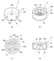
本連結システムは、図1~図3に示すように、ノズル状の雄部材1と、雄部材1が挿入される導通路20を有する雌部材2と、雌部材2の導通路20の開口部20bに設けられる弾性力を有する逆止弁3とを備える。 As shown in FIGS. 1 to 3, this connection system includes a nozzle-
前記雄部材1は、図3に示すように、流体が軸方向に流通して先端部から流出する流通路10を有し、円筒状の径大の第1の雄本体部11と、円筒状の径小の第2の雄本体部12と、第1の雄本体部11と第2の雄本体部12の間に設けられたテーパ状のショルダー部13とを備える。 As shown in FIG. 3, the
前記雌部材2は、図1および図2に示すように、内部を軸方向に貫通する導通路20を有し、軸方向に延びる雌本体部21と、雌本体部21の下方に設けられた環状の座部22と、雌本体部21と座部22の間に設けられたショルダー部23とを備える。この雌部材2は、後述するように包装容器の合成樹脂製のシート材に溶着される。 As shown in FIGS. 1 and 2, the
前記導通路20は、雌部材2の上方端に設けられた挿入口20aから、雌部材2の下方端に設けられた開口部20bまで雌部材2の内部を軸方向に貫通するとともに、雌本体部21、ショルダー部23、座部22の内径に応じて次第に径小となるように形成されており、雄部材1が挿入された際に雄部材1(主に第1の雄本体部11およびショルダー部13)の外面に当接するものとなされている。 The conducting
前記雌本体部21は、下部に平面視ひし形状の溶着部21aが設けられており、該溶着部21aの両側面において包装容器の合成樹脂製のシート材が溶着されることにより、雌本体部21の下方が包装袋の内部となされている。また、雌本体部21は、基端部に2個の環状のリブ21bが形成されており、流体の充填時においてリブ21bの間に治具が掛けられるようになっている。 The female
前記座部22は、雌部材2の開口部20bの周囲に設けられた環状の壁部材であって、基端部に径方向内側に窪んだ凹部22aが形成されている。この凹部22aは、後述するように逆止弁3の取付部33が取り付けられる。 The
前記ショルダー部23は、全体としてテーパ状に形成されており、前記雄部材1が雌部材2の導通路20に挿入された際、雄部材1のショルダー部13が当接することにより雄部材1の挿入時のストッパーとして機能する。 The
前記逆止弁3は、ゴムやエラストマーなどの弾性体から構成されており、図4に示すように、雌部材2の開口部20bを閉鎖または開放する栓部31と、栓部31の周囲に一体的に設けられた膜状弾性体32と、膜状弾性体32の周囲に一体的に設けられた取付部33とを備える。 The
前記栓部31は、逆止弁3の内側に膨らんだ半球面状に形成された弾性体であり、直径が雌部材2の開口部20bの内径よりもやや大きくなるように形成されている。これにより、逆止弁3の閉鎖時において、図2に示すように、栓部31が雌部材2の開口部20bに嵌り込んだ状態となって、雌部材2の開口部20bを完全に閉鎖する一方、逆止弁3の開放時において、図3に示すように、栓部31が雄部材1により押し出された状態となって、雌部材2の開口部20bを開放する。 The
また、前記栓部31は、頂上部において受け部34が段階的に設けられている。この受け部34は、雌部材2の開口部20bの内径よりもやや小さい直径の平面視円形台であって、流体が流通するための4本の線状の流通部34aが形成されている。本実施形態では、この流通部34aは、受け部34の上面の中央部から周端部にかけて放射状に延びる溝状に形成されている。 Further, the
これにより、逆止弁3の閉鎖時において、図2に示すように、受け部34が雌部材2の開口部20bの内部に配置された状態となる一方、逆止弁3の開放時において、図3に示すように、受け部34が雌部材2の開口部20bの下方に配置される。このため、逆止弁3が開放時において、雄部材1の流通路10と、膜状弾性体32と雌部材2の座部22の間の所定の流入空間35とが受け部34の流通部34aを介して連通するため、流体は雄部材1の流通路10と流入空間35の間を流通することができる。 As a result, when the
また、逆止弁3の受け部34は、従来の逆止弁3の受け部34に比べて、雄部材1の先端部との接触面積が大きくなって、雄部材1の先端部を全体的に広く受ける構造であるため、連結システムを繰り返して使用した場合であっても、雄部材1により軸方向に潰れることを軽減または防止することができる。 Further, the receiving
なお、本実施形態では、前記各流通部34aは、栓部31の上面に達する深さに形成されているため、流体が流通部34aをより一層スムーズに流通することができる。 In this embodiment, each of the
前記膜状弾性体32は、栓部31の周囲に一体的に設けられた薄い環状の弾性体であって、流体が通過するための4個の通過孔32aが等間隔に形成されている。この膜状弾性体32は、逆止弁3が雌部材2の座部22に取り付けられた際、自己の有する弾性力に抗してやや伸長状態に変形している。これにより、逆止弁3の閉鎖時において、図2に示すように、膜状弾性体32と雌部材2の座部22が接近した状態となる一方、逆止弁3の開放時において、図3に示すように、栓部31が雄部材1により押し出されるのに伴って下方にさらに伸長状態に変形することにより膜状弾性体32と雌部材2の座部22が離間した状態となり、膜状弾性体32と雌部材2の座部22の間に流体が流入するための所定の大きさの流入空間35が形成される。 The membrane-like
なお、膜状弾性体32の厚みは、流体や粉体の性状や圧力などに応じて適宜設計される。また、通過孔32aの形状や大きさも設計事項であるが、通過孔32aを大きくすると膜状弾性体32が変形した際に生じる応力も小さくなる。 The thickness of the film-like
前記取付部33は、逆止弁3を雌部材2の座部22に取り付けるための弾性体であって、膜状弾性体32の周囲から上方に立設する円筒状の側面部33aと、側面部33aの上端部から径方向内側に屈曲する平面視環状の引掛部33bとを備える。 The
また、取付部33は、側面部33aの内径が雌部材2の座部22の外径よりもやや小さく形成され、かつ側面部33aの内面高さが雌部材2の座部22の先端部から凹部22aの下面までの高さよりもやや低くなるように形成されている。これにより、逆止弁3が雌部材2の座部22に取り付けられた際、引掛部33bが雌部材2の座部22の凹部22aに嵌りこむ態様で掛止されるとともに、側面部33aが弾性力に抗して伸長状態に変形しながら座部22の外周面に密着状態に当接するため、逆止弁3を雌部材2の座部22に抱きかかえる態様で確実に取り付けることができる。 The mounting
次に、本連結システムにおける流体の充填時および吐出時の動作について、図5および図6を参照しつつ説明する。 Next, the operation of this connection system during filling and discharging of fluid will be described with reference to FIGS. 5 and 6. FIG.
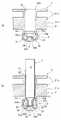
流体の充填時または吐出時において、図5に示すように、雄部材1を雌部材2の導通路20の挿入口20aから開口部20bまで挿入していくと、雄部材1の先端部が逆止弁3の受け部34に到達する。そして、雄部材1の先端部が逆止弁3の受け部34に当接した状態で雄部材1をさらに挿入していくと、逆止弁3の栓部31が雌部材2の開口部20bを開放する。 When the fluid is filled or discharged, as shown in FIG. 5, when the
このとき、図5(b)に示すように、逆止弁3の膜状弾性体32が下方に伸長状態に変形することにより、膜状弾性体32と雌部材2の座部22が離間した状態となり、膜状弾性体32と雌部材2の座部22の間に流体が流入するための所定の大きさの流入空間35が形成される。 At this time, as shown in FIG. 5(b), the membrane
また、同じく図5(b)に示すように、逆止弁3の栓部31が雌部材2の開口部20bを開放することにより、受け部34が雌部材2の開口部20bの下方で露出した状態となり、雄部材1の流通路10と流入空間35が受け部34の流通部34aを介して連通するとともに、流入空間35と雌部材2の外部(包装容器の内部)が膜状弾性体32の通過孔32aを介して連通する。 Also, as shown in FIG. 5B, the
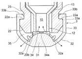
而して、雌部材2が設けられた包装容器に流体を充填する際、逆止弁3の開放時において、図6(下方に向いた矢印)に示すように、雄部材1の流通路10を流れてきた流体が逆止弁3の受け部34の流通部34aを流通して、逆止弁3の膜状弾性体32と雌部材2の間の流入空間35に流入したあと、逆止弁3の膜状弾性体32の通過孔32aから包装容器の内部に流出するため、流体を包装容器の内部に確実に充填することができる。 When the packaging container provided with the
また、雌部材2が設けられた収容容器から流体を吐出する際、逆止弁3の開放時において、図6(上方に向いた矢印)に示すように、包装容器の内部の流体が逆止弁3の膜状弾性体32の通過孔32aから逆止弁3の膜状弾性体32と雌部材2の間の流入空間35に流入したあと、逆止弁3の受け部34の流通部34aを流通して、雄部材1の流通路10に流出するため、包装容器内の流体を外部に吐出することができる。 Further, when the fluid is discharged from the container provided with the
このように、本連結システムによれば、流体が雄部材1の流通路10と雌部材2の外部との間を確実に流通することができるとともに、雄部材1による受け部34の潰れや損傷を軽減または防止することができるため、本連結システムを包装容器に適用した場合、包装容器における流体の充填や吐出を安定的に繰り返して行うことが可能となる。 Thus, according to this connection system, the fluid can reliably flow between the
なお、本実施形態では、前記流通部34aは、4本に形成したが、図7(a)(b)に示すように、その他の本数に形成してもよい。 In this embodiment, four
また、前記流通部34aは、受け部34の中央部から周端部に延びる線状に形成したが、図7(c)(d)(e)に示すように、線状以外の形状に形成してもよい。 Further, the flow-through
また、前記流通部34aは、受け部34の中央部から周端部に延びる放射状に形成したが、放射状に形成しなくてもよい。 Further, although the
また、前記流通部34aは、受け部34の中央部において互いに繋がった状態に形成したが、図7(f)に示すように、互いに繋がっていない状態に形成してもよい。但し、この場合、流体が流通部34aを流通するためには、流通部34aの中央部側の端部が雄部材1の流通路10の内側に配置される必要がある。 Further, although the
また、前記流通部34aは、受け部34の上面において溝状に形成したが、図7(g)に示すように、受け部34の内部を通過する孔状に形成してもよい。この場合、受け部34の中央部に流通部34aに連通する連通孔34bが形成される。 Further, although the
また、前記膜状弾性体32は、図7(h)に示すように、流通部の延長方向の位置に前記通過孔32aが形成されてもよい。 In addition, as shown in FIG. 7(h), the film-like
また、各流通部34aは、受け部34の上面に少なくとも到達する深さに形成したが、所望の流体の流量によっては受け部34の上面に到達しない深さに形成してもよい。 Moreover, although each
また、前記栓部31は、逆止弁3の内側に膨らんだ半球面状に形成したが、その他の形状に形成してもよいし、逆止弁3の内側に膨らまずに膜状弾性体32の厚さ程度に薄く形成してもよい。 Further, although the
また、前記栓部31と受け部34は、段階的な輪郭形状に形成したが、曲線的または直線的に連続する輪郭形状に形成してもよい。要は、逆止弁3が、その輪郭形状にかかわらず、雄部材1の先端部を受けるための受け部34と、雌部材2の開口部20bを閉鎖または開放する栓部31として機能する構造を有していればよい。 Further, although the
また、前記受け部34は、雌部材2の開口部20bの下方で露出するまで雄部材1に押されるものとしたが、逆止弁3の栓部31が雌部材2の開口部20bを開放した場合に流体が流通可能であれば、必ずしも雌部材2の開口部20bから露出しなくてもよい。 Further, although the receiving
また、前記雄部材1の流通路10を流れてきた流体を逆止弁3を介して包装容器内に充填するものとしたが、流体を包装容器のその他の箇所から直接充填してもよい。 Also, although the fluid flowing through the
また、本連結システムを包装容器に適用した場合について説明したが、その他の装置や器具などに適用してもよい。 Moreover, although the case where this connection system is applied to a packaging container has been described, it may be applied to other devices and instruments.
以上、図面を参照して本発明の実施形態を説明したが、本発明は、図示した実施形態のものに限定されない。図示された実施形態に対して、本発明と同一の範囲内において、あるいは均等の範囲内において、種々の修正や変形を加えることが可能である。 Although the embodiments of the present invention have been described above with reference to the drawings, the present invention is not limited to the illustrated embodiments. Various modifications and variations can be added to the illustrated embodiment within the same scope as the present invention or within an equivalent scope.
1…雄部材
10…流通路
11…第1の雄本体部
12…第2の雄本体部
13…ショルダー部
2…雌部材
20…導通路
20a…挿入口
20b…開口部
21…雌本体部
21a…溶着部
21b…リブ
22…座部
22a…凹部
23…ショルダー部
3…逆止弁
31…栓部
32…膜状弾性体
32a…通過孔
33…取付部
33a…側面部
33b…引掛部
34…受け部
34a…流通部
35…流入空間DESCRIPTION OF
Claims (7)
Translated fromJapanese前記逆止弁は、前記雌部材の開口部を閉鎖または開放する栓部と、前記栓部の周囲に一体的に設けられ、流体が通過する通過孔を有する膜状弾性体と、前記膜状弾性体の周囲に一体的に設けられ、前記雌部材に取り付けられる取付部とを備え、
前記栓部は、前記雄部材の先端部を受けるための受け部が一体的に設けられ、該受け部に流体が流通するための一ないし複数の流通部が中央部から周端部に延びる態様で形成されており、
前記雄部材が前記雌部材に挿入される前の前記逆止弁の閉鎖時において、前記膜状弾性体が有する弾性力により前記栓部が前記雌部材の前記開口部を閉鎖する一方、
前記雄部材が前記雌部材に挿入される際の前記逆止弁の開放時において、前記雄部材により前記受け部が押されることにより、前記栓部が前記雌部材の前記開口部を開放するとともに、前記膜状弾性体が前記雌部材との間において流体が流入するための所定の大きさの流入空間を形成することを特徴とする連結システム。A connection comprising: a male member having a flow passage through which fluid flows; a female member having a conducting passage into which the male member is inserted; and a check valve provided at an opening of the conducting passage of the female member a system,
The check valve includes a plug portion for closing or opening the opening of the female member, a film-like elastic body integrally provided around the plug portion and having a passage hole through which a fluid passes, and the film-like elastic body. a mounting portion integrally provided around the elastic body and mounted to the female member;
The plug part is integrally provided with a receiving part for receiving the distal end part of the male member, and one or more circulation parts for circulating the fluid to the receiving part extend from the central part to the peripheral end part. is formed of
When the check valve is closed before the male member is inserted into the female member, the elastic force of the membrane-like elastic body causes the plug to close the opening of the female member,
When the check valve is opened when the male member is inserted into the female member, the receiving portion is pushed by the male member so that the stopper opens the opening of the female member. 1. A connecting system, wherein said membrane-like elastic body and said female member form an inflow space of a predetermined size for inflow of fluid.
前記逆止弁は、前記雌部材の開口部を閉鎖する栓部と、前記栓部の周囲に一体的に設けられ、流体が通過する通過孔を有する膜状弾性体と、前記膜状弾性体の周囲に一体的に設けられ、前記雌部材に取り付けられる取付部とを備え、
前記栓部は、前記雄部材の先端部を受けるための受け部が一体的に設けられ、該受け部に流体が流通するための一ないし複数の流通部が中央部から周端部に延びる態様で形成されていることを特徴とする逆止弁。
A check valve used in the connection system according to any one of claims 1 to 6,
The check valve includes a plug portion that closes the opening of the female member, a film-like elastic body that is integrally provided around the plug portion and has a passage hole through which a fluid passes, and the film-like elastic body. and a mounting portion integrally provided around the periphery of the and attached to the female member,
The plug part is integrally provided with a receiving part for receiving the distal end part of the male member, and one or more circulation parts for circulating the fluid to the receiving part extend from the central part to the peripheral end part. A check valve characterized by being formed of
Priority Applications (2)
| Application Number | Priority Date | Filing Date | Title |
|---|---|---|---|
| JP2021079828AJP7122034B1 (en) | 2021-05-10 | 2021-05-10 | Connection system and check valve |
| PCT/JP2022/014275WO2022239524A1 (en) | 2021-05-10 | 2022-03-25 | Coupling system and check valve |
Applications Claiming Priority (1)
| Application Number | Priority Date | Filing Date | Title |
|---|---|---|---|
| JP2021079828AJP7122034B1 (en) | 2021-05-10 | 2021-05-10 | Connection system and check valve |
Publications (2)
| Publication Number | Publication Date |
|---|---|
| JP7122034B1 JP7122034B1 (en) | 2022-08-19 |
| JP2022173852Atrue JP2022173852A (en) | 2022-11-22 |
Family
ID=82929861
Family Applications (1)
| Application Number | Title | Priority Date | Filing Date |
|---|---|---|---|
| JP2021079828AActiveJP7122034B1 (en) | 2021-05-10 | 2021-05-10 | Connection system and check valve |
Country Status (2)
| Country | Link |
|---|---|
| JP (1) | JP7122034B1 (en) |
| WO (1) | WO2022239524A1 (en) |
Family Cites Families (3)
| Publication number | Priority date | Publication date | Assignee | Title |
|---|---|---|---|---|
| JPH0614578U (en)* | 1992-07-29 | 1994-02-25 | 株式会社ショーワ | Gas filling device for reservoir |
| JP4110315B2 (en)* | 2001-12-25 | 2008-07-02 | 株式会社昭和丸筒 | Connection system with check valve and backflow prevention function |
| US20090267011A1 (en)* | 2008-04-23 | 2009-10-29 | Jason Hatton | Dispensing valve assembly |
- 2021
- 2021-05-10JPJP2021079828Apatent/JP7122034B1/enactiveActive
- 2022
- 2022-03-25WOPCT/JP2022/014275patent/WO2022239524A1/ennot_activeCeased
Also Published As
| Publication number | Publication date |
|---|---|
| JP7122034B1 (en) | 2022-08-19 |
| WO2022239524A1 (en) | 2022-11-17 |
Similar Documents
| Publication | Publication Date | Title |
|---|---|---|
| RU2546411C2 (en) | Double seal system for use with probe | |
| US8402999B2 (en) | Liquid dispensing tap, in particular for liquids with higher density | |
| KR102110129B1 (en) | Cap | |
| US9580214B2 (en) | Port closure system for use with a probe/feed/drain tool | |
| US8083332B2 (en) | Dual seating quick connect valve | |
| JP5138375B2 (en) | Dome check valve and manufacturing method thereof | |
| US20180021560A1 (en) | Medical connector | |
| CN107073254B (en) | Medical connector | |
| KR101932925B1 (en) | cap | |
| KR200490671Y1 (en) | Cosmetic container using eco pump | |
| BRPI0907849B1 (en) | MOUNTING SYSTEM FOR MOUNTING A VALVE TO ACCOMMODATE FLOW OF A SUBSTANCE FROM A SUPPLY OF THE SUBSTANCE | |
| CN102216166B (en) | Port closure system with hydraulic hammer resistance | |
| CN107585428A (en) | Suitable for the locking device for the container for storing liquid | |
| EP3190323A1 (en) | Flow control valve | |
| CN110337333A (en) | distribution device | |
| JP7122034B1 (en) | Connection system and check valve | |
| JP7116970B2 (en) | cap | |
| EP3684708B1 (en) | Valve for a container, corresponding method and use | |
| JP4110315B2 (en) | Connection system with check valve and backflow prevention function | |
| JP2018203369A (en) | cap | |
| EP4052799A1 (en) | Pump container | |
| JP7386530B2 (en) | connection system | |
| JP5836065B2 (en) | Discharge pump | |
| KR20020022571A (en) | Cap | |
| EP1095900A1 (en) | Fluid connector with check-valve |
Legal Events
| Date | Code | Title | Description |
|---|---|---|---|
| A521 | Request for written amendment filed | Free format text:JAPANESE INTERMEDIATE CODE: A523 Effective date:20220629 | |
| A621 | Written request for application examination | Free format text:JAPANESE INTERMEDIATE CODE: A621 Effective date:20220629 | |
| A871 | Explanation of circumstances concerning accelerated examination | Free format text:JAPANESE INTERMEDIATE CODE: A871 Effective date:20220629 | |
| TRDD | Decision of grant or rejection written | ||
| A01 | Written decision to grant a patent or to grant a registration (utility model) | Free format text:JAPANESE INTERMEDIATE CODE: A01 Effective date:20220726 | |
| A61 | First payment of annual fees (during grant procedure) | Free format text:JAPANESE INTERMEDIATE CODE: A61 Effective date:20220801 | |
| R150 | Certificate of patent or registration of utility model | Ref document number:7122034 Country of ref document:JP Free format text:JAPANESE INTERMEDIATE CODE: R150 | |
| R250 | Receipt of annual fees | Free format text:JAPANESE INTERMEDIATE CODE: R250 |