JP2022172603A - Image processing apparatus, image forming apparatus, image processing method, and program - Google Patents
Image processing apparatus, image forming apparatus, image processing method, and programDownload PDFInfo
- Publication number
- JP2022172603A JP2022172603AJP2021078550AJP2021078550AJP2022172603AJP 2022172603 AJP2022172603 AJP 2022172603AJP 2021078550 AJP2021078550 AJP 2021078550AJP 2021078550 AJP2021078550 AJP 2021078550AJP 2022172603 AJP2022172603 AJP 2022172603A
- Authority
- JP
- Japan
- Prior art keywords
- image
- read
- paper
- reading
- code
- Prior art date
- Legal status (The legal status is an assumption and is not a legal conclusion. Google has not performed a legal analysis and makes no representation as to the accuracy of the status listed.)
- Pending
Links
Images


Classifications
- H—ELECTRICITY
- H04—ELECTRIC COMMUNICATION TECHNIQUE
- H04N—PICTORIAL COMMUNICATION, e.g. TELEVISION
- H04N1/00—Scanning, transmission or reproduction of documents or the like, e.g. facsimile transmission; Details thereof
- H04N1/00002—Diagnosis, testing or measuring; Detecting, analysing or monitoring not otherwise provided for
- H04N1/00071—Diagnosis, testing or measuring; Detecting, analysing or monitoring not otherwise provided for characterised by the action taken
- H04N1/00074—Indicating or reporting
- H—ELECTRICITY
- H04—ELECTRIC COMMUNICATION TECHNIQUE
- H04N—PICTORIAL COMMUNICATION, e.g. TELEVISION
- H04N1/00—Scanning, transmission or reproduction of documents or the like, e.g. facsimile transmission; Details thereof
- H04N1/00002—Diagnosis, testing or measuring; Detecting, analysing or monitoring not otherwise provided for
- H04N1/00005—Diagnosis, testing or measuring; Detecting, analysing or monitoring not otherwise provided for relating to image data
- H—ELECTRICITY
- H04—ELECTRIC COMMUNICATION TECHNIQUE
- H04N—PICTORIAL COMMUNICATION, e.g. TELEVISION
- H04N1/00—Scanning, transmission or reproduction of documents or the like, e.g. facsimile transmission; Details thereof
- H04N1/00002—Diagnosis, testing or measuring; Detecting, analysing or monitoring not otherwise provided for
- H04N1/00071—Diagnosis, testing or measuring; Detecting, analysing or monitoring not otherwise provided for characterised by the action taken
- H04N1/00082—Adjusting or controlling
- H—ELECTRICITY
- H04—ELECTRIC COMMUNICATION TECHNIQUE
- H04N—PICTORIAL COMMUNICATION, e.g. TELEVISION
- H04N1/00—Scanning, transmission or reproduction of documents or the like, e.g. facsimile transmission; Details thereof
- H04N1/04—Scanning arrangements, i.e. arrangements for the displacement of active reading or reproducing elements relative to the original or reproducing medium, or vice versa
- H04N1/19—Scanning arrangements, i.e. arrangements for the displacement of active reading or reproducing elements relative to the original or reproducing medium, or vice versa using multi-element arrays
- H04N1/191—Scanning arrangements, i.e. arrangements for the displacement of active reading or reproducing elements relative to the original or reproducing medium, or vice versa using multi-element arrays the array comprising a one-dimensional array, or a combination of one-dimensional arrays, or a substantially one-dimensional array, e.g. an array of staggered elements
- H04N1/1911—Simultaneously or substantially simultaneously scanning picture elements on more than one main scanning line, e.g. scanning in swaths
- H04N1/1916—Simultaneously or substantially simultaneously scanning picture elements on more than one main scanning line, e.g. scanning in swaths using an array of elements displaced from one another in the main scan direction, e.g. a diagonally arranged array
- H04N1/1917—Staggered element array, e.g. arrays with elements arranged in a zigzag
- H—ELECTRICITY
- H04—ELECTRIC COMMUNICATION TECHNIQUE
- H04N—PICTORIAL COMMUNICATION, e.g. TELEVISION
- H04N1/00—Scanning, transmission or reproduction of documents or the like, e.g. facsimile transmission; Details thereof
- H04N1/04—Scanning arrangements, i.e. arrangements for the displacement of active reading or reproducing elements relative to the original or reproducing medium, or vice versa
- H04N1/19—Scanning arrangements, i.e. arrangements for the displacement of active reading or reproducing elements relative to the original or reproducing medium, or vice versa using multi-element arrays
- H04N1/191—Scanning arrangements, i.e. arrangements for the displacement of active reading or reproducing elements relative to the original or reproducing medium, or vice versa using multi-element arrays the array comprising a one-dimensional array, or a combination of one-dimensional arrays, or a substantially one-dimensional array, e.g. an array of staggered elements
- H04N1/192—Simultaneously or substantially simultaneously scanning picture elements on one main scanning line
- H04N1/193—Simultaneously or substantially simultaneously scanning picture elements on one main scanning line using electrically scanned linear arrays, e.g. linear CCD arrays
- H04N1/1932—Simultaneously or substantially simultaneously scanning picture elements on one main scanning line using electrically scanned linear arrays, e.g. linear CCD arrays using an array of elements displaced from one another in the sub scan direction, e.g. a diagonally arranged array
- H04N1/1933—Staggered element arrays, e.g. arrays with elements arranged in a zigzag
- H—ELECTRICITY
- H04—ELECTRIC COMMUNICATION TECHNIQUE
- H04N—PICTORIAL COMMUNICATION, e.g. TELEVISION
- H04N1/00—Scanning, transmission or reproduction of documents or the like, e.g. facsimile transmission; Details thereof
- H04N1/32—Circuits or arrangements for control or supervision between transmitter and receiver or between image input and image output device, e.g. between a still-image camera and its memory or between a still-image camera and a printer device
- H04N1/32101—Display, printing, storage or transmission of additional information, e.g. ID code, date and time or title
- H04N1/32128—Display, printing, storage or transmission of additional information, e.g. ID code, date and time or title attached to the image data, e.g. file header, transmitted message header, information on the same page or in the same computer file as the image
- H04N1/32133—Display, printing, storage or transmission of additional information, e.g. ID code, date and time or title attached to the image data, e.g. file header, transmitted message header, information on the same page or in the same computer file as the image on the same paper sheet, e.g. a facsimile page header
- H—ELECTRICITY
- H04—ELECTRIC COMMUNICATION TECHNIQUE
- H04N—PICTORIAL COMMUNICATION, e.g. TELEVISION
- H04N1/00—Scanning, transmission or reproduction of documents or the like, e.g. facsimile transmission; Details thereof
- H04N1/387—Composing, repositioning or otherwise geometrically modifying originals
- H04N1/3876—Recombination of partial images to recreate the original image
- H—ELECTRICITY
- H04—ELECTRIC COMMUNICATION TECHNIQUE
- H04N—PICTORIAL COMMUNICATION, e.g. TELEVISION
- H04N2201/00—Indexing scheme relating to scanning, transmission or reproduction of documents or the like, and to details thereof
- H04N2201/32—Circuits or arrangements for control or supervision between transmitter and receiver or between image input and image output device, e.g. between a still-image camera and its memory or between a still-image camera and a printer device
- H04N2201/3201—Display, printing, storage or transmission of additional information, e.g. ID code, date and time or title
- H04N2201/3269—Display, printing, storage or transmission of additional information, e.g. ID code, date and time or title of machine readable codes or marks, e.g. bar codes or glyphs
Landscapes
- Engineering & Computer Science (AREA)
- Multimedia (AREA)
- Signal Processing (AREA)
- Health & Medical Sciences (AREA)
- General Health & Medical Sciences (AREA)
- Biomedical Technology (AREA)
- General Engineering & Computer Science (AREA)
- Physics & Mathematics (AREA)
- Editing Of Facsimile Originals (AREA)
- Electromagnetism (AREA)
- Image Processing (AREA)
- Facsimile Image Signal Circuits (AREA)
- Image Analysis (AREA)
- Accessory Devices And Overall Control Thereof (AREA)
- Record Information Processing For Printing (AREA)
- Facsimile Scanning Arrangements (AREA)
- Toxicology (AREA)
- Artificial Intelligence (AREA)
- Computer Vision & Pattern Recognition (AREA)
- General Physics & Mathematics (AREA)
- Theoretical Computer Science (AREA)
- Facsimiles In General (AREA)
Abstract
Description
Translated fromJapanese本開示の技術は、印刷処理された用紙を検査する技術に関する。The technology of the present disclosure relates to technology for inspecting printed paper.
バーコード等のコード画像が印刷された用紙を読み取ることで得られた読取画像から当該コード画像を読み取って、コード画像に埋め込まれた所定の情報を抽出する方法がある。所定の情報に基づき用紙に印刷された内容を取得することで、印刷処理された用紙に対して、その用紙に印刷された内容に応じた検査をすることができる。 There is a method of extracting predetermined information embedded in the code image by reading the code image from a read image obtained by reading a sheet on which a code image such as a bar code is printed. By acquiring the content printed on the paper based on the predetermined information, it is possible to inspect the printed paper according to the content printed on the paper.
所定の情報を抽出するための読取画像を取得する方法として、画像を印刷する印刷装置で搬送できる用紙の最大幅未満の読取範囲である読取センサを複数組み合わせて、最大用紙幅の印刷用紙の読取画像を取得する方法がある。 As a method of acquiring a read image for extracting predetermined information, a combination of multiple reading sensors whose reading range is less than the maximum width of the paper that can be conveyed by the printing device that prints the image is used to read the print paper with the maximum paper width. There is a way to get the image.
特許文献1には、2つの読取ラインセンサが原稿を読み取ることで得られた夫々の画像を合成することで読取ラインセンサの読取範囲の幅よりも大きな幅の原稿を読み取る方法が記載されている。 Japanese Patent Application Laid-Open No. 2002-200001 describes a method of reading a document having a width larger than the width of the reading range of the reading line sensors by synthesizing respective images obtained by reading the document with two reading line sensors. .
特許文献1の方法のように、2つの読取センサが用紙を読み取ることで得られた2つの画像を合成して合成画像を生成する場合、合成画像の境界部で画素ずれが発生することがある。バーコードのようなコード画像のある領域に画素ずれが発生すると、合成画像から正しくバーコードを読み取ることができない虞がある。正しくバーコードを読み取ることができないと、バーコードに埋め込まれた所定の情報の抽出に失敗してしまうことがある。 When two images obtained by reading paper with two reading sensors are combined to generate a composite image, as in the method of
本開示の画像処理装置は、所定の情報を符号化したコード画像が印刷された用紙の検査を行うための画像処理装置であって、前記用紙内における前記コード画像の位置および大きさを表す位置情報を取得する第1の取得手段と、前記用紙内の異なる部分を複数の読取手段がそれぞれ読み取ることで得られた複数の読取画像であって、合成することで前記用紙の全体を表す画像となる複数の読取画像を取得する第2の取得手段と、前記複数の読取画像のいずれかが、前記コード画像の全体が含まれる読取画像であるかを、前記位置情報に基づき決定する決定手段と、前記コード画像の全体が含まれる読取画像がある場合、当該読取画像における前記コード画像を読み取って、前記所定の情報を抽出する抽出手段と、を有することを特徴とする。 An image processing apparatus according to the present disclosure is an image processing apparatus for inspecting a sheet on which a code image encoding predetermined information is printed, wherein the position and size of the code image in the sheet are a first obtaining means for obtaining information; and a plurality of read images obtained by reading different portions of the paper by a plurality of reading means, and combining the images to represent the entire paper. a second obtaining means for obtaining a plurality of read images, and a determining means for determining whether any one of the plurality of read images is a read image including the entire code image based on the position information; and extracting means for extracting the predetermined information by reading the code image in the read image when there is a read image including the entire code image.
本開示の技術によれば、コード画像が印刷された用紙を複数の読取装置で読み取る場合であっても、コード画像に埋め込まれた所定の情報を抽出することができる。 According to the technique of the present disclosure, it is possible to extract predetermined information embedded in the code image even when a sheet on which the code image is printed is read by a plurality of reading devices.
以下、本開示の技術を実施するための形態について図面を用いて説明する。以下の説明において、外部コントローラは、画像処理コントローラ、デジタルフロントエンド、プリントサーバ、DFEなどと呼ばれることもある。画像形成装置は、複合機、マルチファンクションペリフェラル、MFPと呼ばれることもある。 Embodiments for implementing the technology of the present disclosure will be described below with reference to the drawings. In the following description, an external controller may also be referred to as an image processing controller, digital front end, print server, DFE, or the like. An image forming apparatus is also called a multifunction peripheral, a multifunction peripheral, or an MFP.
<実施形態1>
[システム構成]
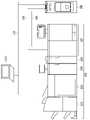
図1は、本実施形態に係る印刷システムの構成を説明するための全体図である。印刷システムは、画像形成装置101と外部コントローラ102とを備える。画像形成装置101および外部コントローラ102は内部LAN105とビデオケーブル106を介して通信可能に接続されている。外部コントローラ102は外部LAN104を介してクライアント端末であるPC(personal computer)103と通信可能に接続されており、PC103から外部コントローラ102に対して印刷指示が行われる。<
[System configuration]
FIG. 1 is an overall view for explaining the configuration of a printing system according to this embodiment. The printing system includes an
PC103には、外部コントローラ102で処理可能な印刷記述言語に印刷データを変換する機能を有するプリンタドライバがインストールされている。印刷を指示するユーザは各種アプリケーションからプリンタドライバを介して印刷指示を行うことができる。プリンタドライバはユーザからの印刷指示に基づいて外部コントローラ102に対して印刷データを送信する。外部コントローラ102はPC103から印刷指示を受け取ると、印刷データに対してデータ解析およびラスタライズ処理を行い、画像形成装置101に対して印刷データを投入し印刷指示を行う。 The PC 103 is installed with a printer driver having a function of converting print data into a print description language that can be processed by the
次に画像形成装置101について説明する。画像形成装置101は、印刷装置107、インサータ108、検査装置109、大容量スタッカ110およびフィニッシャ111を有する。本実施形態の画像形成装置101は、複数の異なる機能を持つ装置で構成され、製本などの複雑な印刷処理が可能に構成されている。 Next, the
印刷装置107は、印刷装置107の下部にある給紙部230(図2参照)から搬送される用紙に対してトナーを用いて画像を形成する装置である。 The
インサータ108は、用紙を挿入するための装置であり、印刷装置107で印刷され搬送された用紙群に対して、任意の位置で用紙を挿入することができる。 The
検査装置109は、印刷装置107で印刷処理された用紙を読み取り、印刷された画像が正常かどうか等の検査をするための装置である。検査装置109における検査の詳細は後述する。 The
大容量スタッカ110は、大容量の用紙を積載することが可能なスタッカである。フィニッシャ111は、搬送された用紙に対してフィニッシング処理を加える装置である。フィニッシャ111は、ステイプルやパンチ、中綴じ製本などのフィニッシング処理を行うことが可能であり、フィニッシング処理された用紙は排紙トレイに排紙される。 The large-
図1で説明した印刷システムは画像形成装置101に外部コントローラ102が接続された構成であるが、印刷システムは図1の構成に限定されない。例えば、画像形成装置101を外部LAN104に接続し、クライアントPC103から、画像形成装置101が処理可能な印刷データを直接送信する構成でもよい。この場合、画像形成装置101において、データ解析やラスタライズ処理が行われ、印刷処理が実行される。 Although the printing system described with reference to FIG. 1 has a configuration in which an
[印刷システムに係る各装置の構成について]
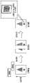
図2は、画像形成装置101、外部コントローラ102、及びクライアントPC103のそれぞれに含まれる各部の構成を説明するためのブロック図である。[Regarding the configuration of each device related to the printing system]
FIG. 2 is a block diagram for explaining the configuration of each unit included in each of the
まず画像形成装置101の印刷装置107の構成について説明する。印刷装置107は、通信I/F217、LANI/F218、ビデオI/F220、HDD221、CPU222、メモリ223、操作部224、ディスプレイ225を有する。さらに印刷装置107は、原稿読取部226、レーザ露光部227、作像部228、定着部229、給紙部230を有する。それぞれの構成要素はシステムバス231を介して接続される。 First, the configuration of the
通信I/F217は通信ケーブル270を介してインサータ108、検査装置109、大容量スタッカ110、及びフィニッシャ111と接続され、それぞれの装置の制御のための通信が行われる。LANI/F218は内部LAN105を介して外部コントローラ102と接続され、印刷データなどの通信が行われる。ビデオI/F220はビデオケーブル106を介して外部コントローラ102と接続され、画像データなどの通信が行われる。 The communication I/
HDD221は、プログラムやデータが保存された記憶装置である。CPU222はHDD221に保存されたプログラム等に基づいて、画像処理の制御および印刷の制御を包括的に行う。メモリ223は、CPU222が各種処理を行う際に必要となるプログラム、画像データ等を記憶しており、ワークエリアとして動作する。操作部224は、ユーザからの各種設定の入力および指示を受け付ける。ディスプレイ225は、画像処理の設定情報、印刷状況、設定のための情報、および印刷ジョブの処理状況等を表示する。 The HDD 221 is a storage device that stores programs and data. The
原稿読取部226は、コピー機能およびスキャン機能を使用する際に原稿を読み取る処理を行う。載置された用紙に対して露光ランプを照らしながらCCDカメラで画像を撮影することで原稿を読み取る。 The
レーザ露光部227は、トナー像を転写するために感光ドラムにレーザ光を照射するための一次帯電、およびレーザ露光を行う。レーザ露光部227では、まず感光ドラム表面を均一なマイナス電位に帯電させる一次帯電が行われる。次に、レーザドライバーがレーザ光を、ポリゴンミラーで反射角度を調節しながら感光ドラムに照射する。これにより照射した部分のマイナス電荷が中和され、静電潜像が形成される。 The
作像部228は、用紙に対してトナーを転写するためのユニットである。作像部228は、現像ユニット、転写ユニット、トナー補給部等を有し、感光ドラム上のトナーを用紙に転写する。現像ユニットにおいては、現像シリンダーからマイナスに帯電したトナーを感光ドラム表面の静電潜像に付着させ、可視像化する。転写ユニットにおいては、一次転写ローラーにプラス電位を印可し感光ドラム表面のトナーを転写ベルトに転写する一次転写、二次転写外ローラーにプラス電位を印可し転写ベルト上のトナーを用紙に転写する二次転写が行われる。 The
定着部229は、用紙上のトナーを熱と圧力で用紙に溶解固着するためのユニットであり、ハロゲンヒータなどを熱源とする加熱ヒーター、定着ベルト、加圧ベルト等を有する。給紙部230は用紙を給紙するユニットであり、ローラーおよび各種センサにより用紙の給紙動作、搬送動作を制御する。 The fixing
上述した各部によって行われる印刷装置107の印刷動作の原理は次のとおりである。レーザ露光部227は、画像データに応じて変調された、レーザ光などの光線をポリゴンミラー等の回転多面鏡により反射して走査光として感光ドラムに照射する。このレーザ光により感光ドラム上に形成された静電潜像はトナーによって現像される。作像部228は、転写ドラムに貼り付けられた用紙に、そのトナー像を転写する。この一連の画像形成プロセスをイエロー(Y)、マゼンタ(M)、シアン(C)、ブラック(K)のトナーに対して順次実行することにより、用紙上にフルカラー画像が形成される。フルカラー画像が形成された転写ドラム上の用紙は定着部229へ搬送される。定着部229は、トナー像が転写された用紙上のトナーを、熱と圧力によって溶解して用紙に定着させる。 The principle of the printing operation of the
次にインサータ108の構成について説明する。インサータ108は、通信I/F232、CPU233、メモリ234、および給紙制御部235を有する。それぞれの構成要素はシステムバス236を介して接続される。 Next, the configuration of the
通信I/F232は通信ケーブル270を介して印刷装置107と接続され、インサータ108の制御に必要な通信が行われる。CPU233は、メモリ234に格納された制御プログラムに応じて、給紙に必要な各種制御を行う。メモリ234は、制御プログラムが保存された記憶装置である。給紙制御部235は、CPU218の指示に基づき、後述する搬送パスを構成するローラーとセンサを制御しながら、インサータトレイ321(図3参照)、または印刷装置107から搬送された用紙の給紙または搬送を制御する。 The communication I/
次に、検査装置109の構成について説明する。検査装置109は、通信I/F237、CPU238、メモリ239、読取部240、読取部241、表示部242、および操作部243を有する。それぞれの構成要素はシステムバス244を介して接続される。 Next, the configuration of the
通信I/F237は通信ケーブル270を介して印刷装置107と接続され、検査装置109の制御に必要な通信が行われる。CPU238は、メモリ239に格納された制御プログラムに応じて、後述する検査に必要な各種制御を行う。メモリ239は、制御プログラムが保存された記憶装置である。表示部242は、検査装置109によって行われた検査の結果、または設定画面などを表示する。操作部243は、ユーザによって操作され、検査装置109の設定変更、後述する正解画像等の登録の指示を受け付ける。 The communication I/
読取部240および読取部241は、CPU238の指示に基づき、搬送された印刷用紙を読み取ることが可能な装置である。読取部240は用紙の左側を読み取る装置であり、読取部241は用紙の右側を読み取る装置である。なお、用紙のサイズによっては、一方の読取部のみでも用紙の全体を読み取ることができる。読取部240および読取部241が印刷用紙を読み取ることで得られたそれぞれの読取画像は、後述する検査で用いられる。 The
なお、印刷用紙を読み取るための読取部240、241は、検査装置109よりも上流の装置、例えば、印刷装置107に含まれていてもよい。その場合、検査装置109は、読取部240、241が読み取ることで得られた読取画像を取得して検査をすればよい。読取部240、241および検査処理の詳細は後述する。 Note that the reading
次に大容量スタッカ110の構成について説明する。大容量スタッカ110は、通信I/F245、CPU246、メモリ247、排紙制御部248を有する。それぞれの構成要素はシステムバス249を介して接続される。通信I/F245は通信ケーブル270を介して印刷装置107と接続され、大容量スタッカ110の制御に必要な通信が行われる。CPU246は、メモリ247に格納された制御プログラムに応じて、排紙に必要な各種制御を行う。メモリ247は、制御プログラムが保存された記憶装置である。排紙制御部248は、CPU246からの指示に基づき、搬送された用紙をスタックトレイ341(図3参照)、エスケープトレイ346(図3参照)、または後続のフィニッシャ111の何れかに搬送するための制御を行う。 Next, the configuration of the large-
次にフィニッシャ111の構成について説明する。フィニッシャ111は、通信I/F250、CPU251、メモリ252、排紙制御部253、フィニッシング処理部254を有する。それぞれの構成要素はシステムバス255を介して接続される。通信I/F250は通信ケーブル270を介して印刷装置107と接続され、フィニッシャ111の制御に必要な通信が行われる。CPU251は、メモリ252に格納された制御プログラムに応じて、フィニッシングや排紙に必要な各種制御を行う。メモリ252は、制御プログラムが保存された記憶装置である。排紙制御部253は、CPU251からの指示に基づき、用紙の搬送、排紙を制御する。フィニッシング処理部254は、CPU251からの指示に基づき、後述するフィニッシング処理を制御する。 Next, the configuration of the
次に、外部コントローラ102の構成について説明する。外部コントローラ102は、CPU208、メモリ209、HDD210、キーボード211、ディスプレイ212、LANI/F213,LANI/F214、ビデオI/F215を有する。それぞれの構成要素はシステムバス216を介して接続されている。CPU208は、HDD210に保存されたプログラムまたはデータに基づいて、PC103から印刷データの受信、RIP処理、画像形成装置101への印刷データの送信などの処理を包括的に実行する。メモリ209は、CPU208が各種処理を行う際に必要なプログラムおよびデータを記憶し、ワークエリアとして動作する。HDD230は、印刷処理などの動作に必要なプログラムおよびデータを記憶する。キーボード211は、外部コントローラ102の操作指示をユーザが入力するための装置である。ディスプレイ212は、外部コントローラ102の実行アプリケーション等の情報を映像信号に基づき静止画や動画として表示する。LANI/F213は、外部LAN104を介してPC103と接続され、印刷指示などの通信が行われる。LANI/F214は、内部LAN105を介して画像形成装置101と接続され、印刷指示などの通信が行われる。ビデオI/F215は、ビデオケーブル106を介して画像形成装置101と接続され、印刷データなどの通信が行われる。 Next, the configuration of the
次に、PC103の構成について説明する。PC103は、CPU201、メモリ202、HDD203、キーボード204、ディスプレイ205、LANI/F206を有する。それぞれの構成要素はシステムバス207を介して接続されている。CPU201は、HDD203に保存された文書処理プログラム等に基づいて印刷データの生成または印刷指示を実行する。またCPU201は、システムバス207に接続される各構成要素を包括的に制御する。メモリ202は、CPU201が各種処理を行う際に必要となるプログラムおよびデータを記憶しており、ワークエリアとして動作する。HDD203は、印刷処理などの動作に必要なプログラムおよびデータを記憶する。キーボード204はユーザの入力および指示を受け付ける装置である。ディスプレイ205は、PC103の実行アプリケーション等の情報を映像信号により静止画や動画として表示する。LANI/F206は、外部LAN104と接続されており、印刷指示などの通信を行う。 Next, the configuration of the
図2では、外部コントローラ102と画像形成装置101とは内部LAN105とビデオケーブル106とによって接続されているが、印刷に必要なデータの送受信が行える構成であればよい。例えば、外部コントローラ102と画像形成装置101とはビデオケーブル106のみで接続されてもよい。 In FIG. 2, the
また、上述したメモリ202、209、223、234、239、247、252はそれぞれ、データやプログラムを保持するための記憶装置でよい。たとえば、揮発性のRAM、不揮発性のROM、内蔵HDD、外付けHDD、USBメモリなどで代替した構成でもよい。 Also, the
[印刷動作時の用紙の搬送について]
図3は、画像形成装置101の概略構成を表すメカ断面図である。図3を用いて、印刷動作時の用紙の搬送について説明する。[Conveying paper during printing]
FIG. 3 is a mechanical cross-sectional view showing a schematic configuration of the
はじめに、印刷装置107における用紙の搬送について説明する。給紙デッキ301、302は、各種用紙が収容可能に構成されており、収容された用紙の最上位の用紙一枚のみが分離され、用紙搬送パス303へ搬送することが可能に構成されている。給紙デッキ301、302は給紙部230に含まれる。 First, the conveyance of paper in the
作像部228における用紙の搬送を説明する。現像ステーション304~307は、カラー画像を形成するために、それぞれY、M、C、Kの有色トナーを用いてトナー像を形成する。ここで形成されたトナー像は中間転写ベルト308に一次転写される。中間転写ベルト308は図3での時計回りに回転し、二次転写位置309で用紙搬送パス303から搬送されてきた用紙へとトナー像が転写される。 Conveyance of paper in the
定着部229における用紙の搬送を説明する。第1定着ユニット311はトナー像を用紙へ定着させるための装置である。第1定着ユニット311は加圧ローラーと加熱ローラーとを備え、各ローラーの間を用紙が通過することにより、トナーを溶融・圧着することで用紙にトナー像を定着させる。第1定着ユニット311を抜けた用紙は用紙搬送パス312を通って、インサータ108と接続する用紙搬送パス315へと搬送される。用紙の種類によって定着のためにさらに溶融・圧着が必要な場合は、第1定着ユニット311を通過した後、上の用紙搬送パス314を使って第2定着ユニット313へと搬送される。その場合、用紙は第2定着ユニット313で追加の溶融・圧着が施された後、用紙搬送パス315へと搬送される。画像形成モードが両面の場合、用紙は、用紙反転パス316へと搬送される。その後、用紙反転パス316で反転した後、用紙は両面搬送パス317へと搬送され、二次転写位置309によって用紙裏面へ画像転写が行われる。 Conveyance of paper in the
インサータ108は、インサータトレイ321を備え、用紙搬送パス322を通じてインサータトレイ321に給紙された用紙を搬送パス323へ合流可能に構成されている。この構成により、印刷装置107から搬送される一連の用紙群の任意の位置で用紙を挿入させ、用紙を後続装置へ搬送させることが可能となる。インサータ108を通過した用紙は検査装置109へ搬送される。 The
検査装置109では、カメラ331およびカメラ334と、カメラ332およびカメラ335とが対向する形で配置されている。カメラ331およびカメラ334は用紙の上面(表面)を、カメラ332と335は用紙の下面(裏面)を読み取るための読取部である。カメラ331およびカメラ332は、読取部240に対応し用紙の左側を読み取るための装置である。カメラ334およびカメラ335は読取部241に対応し用紙の右側を読み取るための装置である。 In the
用紙搬送パス333に搬送された用紙がカメラの撮影範囲に到達したタイミングで、カメラ331、334、またはカメラ332、335が用紙を撮影することで印刷用紙を読み取る。印刷用紙を読み取ることによって得られた読取画像を解析することで、印刷用紙に含まれる画像が正常に印刷されているかを判定することができる。検査装置109を通過した用紙は大容量スタッカ110に搬送される。 At the timing when the paper conveyed to the
大容量スタッカ110は、用紙を積載するトレイであるスタックトレイ341を有する。検査装置109を通過した用紙は用紙搬送パス344へ搬送される。用紙は用紙搬送パス344から用紙搬送パス345を経由して、スタックトレイ341に積載される。さらに大容量スタッカ110は、排紙トレイとしてエスケープトレイ346を有する。エスケープトレイ346は、検査装置109によって不良用紙と判定された印刷用紙を排紙するために使用される排紙トレイである。エスケープトレイ346に用紙を排紙する場合、用紙搬送パス344から用紙搬送パス347を経由してエスケープトレイ346へ用紙が搬送される。 The large-
フィニッシャ111へ用紙を搬送する場合には、用紙搬送パス348を経由して用紙が搬送される。反転部349は用紙を反転する際に機能する。搬入された用紙の向きと搬出時点での用紙の向きが同一となるようにスタックトレイ341に用紙を積載する場合、反転部349が用紙を反転することができる。エスケープトレイ346、またはフィニッシャ111へ搬送する場合は、積載時にフリップせずにそのまま用紙を排紙するため、反転部349へ用紙は搬送されない。 When conveying a sheet to the
フィニッシャ111はユーザの指示に応じて、搬送された印刷用紙に対してフィニッシング処理を行う装置である。フィニッシャ111は、例えば、ステイプル(1個所・2箇所綴じ)、パンチ(2穴・3穴)、または中とじ製本等のフィニッシング処理を行う機能を実現するための装置を有する。 A
また、フィニッシャ111は、2つの排紙トレイ351、352を備える。排紙トレイ351へは用紙搬送パス353を経由して用紙が排紙される。用紙搬送パス353ではフィニッシング処理を行うことはできない。ステイプルまたはパンチのフィニッシング処理を行う場合は、用紙搬送パス354を経由して処理部355に搬送される。処理部355はユーザが指定したフィニッシング処理を実行する。フィニッシング処理された印刷用紙は排紙トレイ352へ排紙される。排紙トレイ351、352はそれぞれ昇降することが可能であり、排紙トレイ351を下降させ、処理部355でフィニッシング処理された印刷用紙を排紙トレイ351へ積載するように動作することも可能である。 The
中とじ製本のフィニッシング処理が指定された場合、中とじ処理部356へ用紙が搬送される。中とじ処理部356は用紙中央にステイプル処理をした後、用紙を二つ折りにする中とじ製本処理を行うことができる。中とじ製本処理された印刷用紙は、用紙搬送パス357を経由して中とじ製本トレイ358へ排紙される。中とじ製本トレイ358はベルトコンベア構成になっており、中とじ製本トレイ358上に積載された中とじ製本束は左側へ搬送される構成となっている。 When finishing processing for saddle stitch binding is specified, the sheets are conveyed to the saddle
[検査処理の概要について]
検査装置109は、例えば、印刷装置107によって画像が印刷された用紙(印刷用紙または印刷物と称する)が不良用紙であるかを決定することができる。不良用紙とは、用紙に形成された画像が、本来に形成されるべき画像とは異なり、罫線の欠け、画像抜け、印刷不良、および色ずれのある画像となった用紙、または一部が折れ曲がった用紙をいう。例えば、後述するIDが符号化されて埋め込まれた画像(例えば、バーコード)の一部が欠落した用紙、本来用紙に形成されるべき画像の順序とは異なる順序で画像が形成された用紙も不良用紙に含まれる。印刷用紙が不良用紙であると判定された場合、前述したように不良用紙は不良用紙と判定されなかった印刷用紙(正常用紙)とは別の排紙先に排紙される。このため、不良用紙が正常用紙に混入することが抑制され、オペレータが不良用紙を廃棄することが可能となる。[Overview of inspection process]
The
検査装置109による検査処理では、事前に印刷して得られた十分な品位のある印刷用紙を読み取り、その結果得られた画像が「正解画像(マスタ画像、またはリファレンス画像ともよぶ)」として登録される。検査装置109の読取部240、241が検査対象の印刷用紙を読み取って得られた読取画像と、正解画像とを比較し、差分を検出することによって印刷用紙が不良用紙であるかを判定することができる。この検査を画像検査とよぶ。 In the inspection process by the
また、検査装置109は、用紙内のID(識別子)を表す画像(コード画像とも称する)を読み取ることでIDを抽出することが可能に構成されている。コード画像は、例えば、一次元または二次元のバーコードである。本実施形態の検査装置109は、「データ検査」が実行可能に構成されており、抽出されたIDは、例えば、データ検査の処理において用いられる。他にも、IDが正しく抽出された場合、その印刷用紙は正常用紙と判定するようにコード画像が用いられてもよい。 Also, the
「データ検査」では、宛名や請求金額等のような印刷用紙ごとに異なる個別情報が印刷された印刷用紙において、個別情報を示す画像(文字列)が正しく印刷されているかが検査される。各印刷用紙には個別情報を示す文字列とともに、印刷されるべき個別情報を示す文字列を取得するためのIDが埋め込まれたコード画像が印刷される。 In the "data inspection", it is inspected whether or not the image (character string) indicating the individual information is correctly printed on the printing paper on which the individual information such as the address and the billing amount, which differ for each printing paper, is printed. A code image in which an ID for acquiring a character string indicating the individual information to be printed is embedded is printed on each printing sheet together with the character string indicating the individual information.
例えば、請求書を用紙に印刷する場合、データ検査における検査項目は請求額の合計金額を示す文字列であるとする。正解画像の領域のうち、データ検査における検査項目のある領域をデータ検査領域とよぶ。メモリ239には、例えば、請求先を示すIDと請求先へ請求額の合計金額の数値とが対応付けられたデータベースが予め生成されている。検査装置109は、読取画像からIDを抽出することで、そのデータベースから、抽出したIDに対応付けられた請求額合計を示す数値を取得する。データ検査における検査項目(例えば、請求額の合計金額)の文字列が印刷される領域であるデータ検査領域の位置情報は予め登録されている。このため、IDに基づき取得した数値を示す文字列と、印刷用紙のデータ検査領域から検出された文字列と、を比較することで、印刷用紙に個別情報が正しく印刷されているかを検査できる。なお、コード画像に、検査項目の文字列を埋め込んで、コード画像から文字列を抽出して検査を行ってもよい。データ検査の詳細は後述する。 For example, when printing a bill on paper, the inspection item in the data inspection is a character string indicating the total billed amount. Among the regions of the correct image, a region having inspection items in the data inspection is called a data inspection region. In the
[データ検査処理の比較例について]
本実施形態の検査装置109は、印刷用紙を、読取部240と読取部241との2つの読取部で読み取ることが可能に構成されている。例えば、印刷用紙の表面を読み取る読取部240、241は、カメラ331、334であり、カメラ331、334が並んで配置されている。印刷用紙の表面を読み取る場合、読取部240に対応するカメラ331が印刷用紙の左側を撮影することで印刷用紙の左側を読み取り、読取部241に対応するカメラ334が印刷用紙の右側を撮影することで印刷用紙の右側を読み取る。以下、読取部240、241が、印刷用紙の表面のみを読み取る場合について説明する。[Comparison example of data inspection processing]
The
本実施形態の読取部240、241のうちの夫々の読取範囲(読取領域)の幅は、画像形成装置101が搬送することが可能な用紙の最大用紙幅未満であるものとして説明する。このため、読取部を複数配置して、夫々の読取部から得られた読取画像を合成することで最大用紙幅の印刷用紙の読取画像が生成可能に構成されている。このような読取部を複数配置する構成とすることで、最大用紙幅の印刷用紙を読み取ることが可能な1つの読取部を配置するよりも、コストを低減することができる。 The width of each reading range (reading area) of the reading
図4は、2つの読取部240、241が読み取ることで得られた2つの読取画像に基づき、データ検査をする方法の比較例を説明するため図である。図4では、コード画像が二次元バーコードである例を示している。 FIG. 4 is a diagram for explaining a comparative example of a method of inspecting data based on two read images obtained by reading by the two reading
比較例は、2つの読取画像からIDを抽出するには、各読取部で読み取った2つの読取画像を合成して得られた合成画像から二次元バーコードを読み取ることでIDを抽出する例である。しかしながら、合成画像のつなぎ目ではズレが生じてしまうことがある。このため、合成画像のつなぎ目に二次元バーコードが存在する場合、合成によるズレが生じすると、比較例では正しい二次元バーコードを読み取ることができなくなることがある。このため比較例では、IDの抽出に失敗してしまうことがある。 A comparative example is an example in which an ID is extracted from two read images by reading a two-dimensional barcode from a composite image obtained by combining two read images read by each reading unit. be. However, there may be a gap at the joint of the synthesized image. For this reason, when a two-dimensional barcode exists at the joint of the composite image, if a shift occurs due to composition, it may not be possible to read the correct two-dimensional barcode in the comparative example. Therefore, in the comparative example, ID extraction may fail.
そこで本実施形態では、2つの読取部によって読み取られた2つの読取画像からIDを適切に抽出する方法を説明する。なお、本実施形態では、印刷用紙を読み取る手段である読取部は、カメラであるものとして説明するが、本実施形態の読取部は、スキャナでもよい。つまりカメラの代わりにカメラの読取範囲である撮影範囲の幅方向のサイズがスキャナの幅方向のサイズであるラインスキャナが配置されていてもよい。また、本実施形態では、2つの読取部で印刷用紙の全体を読み取るものとして説明するが、本実施形態は、3つ以上の読取部で印刷用紙の全体を読み取る構成でもよい。 Therefore, in this embodiment, a method for appropriately extracting an ID from two read images read by two reading units will be described. In this embodiment, the reading unit, which is means for reading printing paper, is described as being a camera, but the reading unit in this embodiment may be a scanner. In other words, instead of the camera, a line scanner may be arranged in which the size in the width direction of the photographing range, which is the reading range of the camera, is the size in the width direction of the scanner. Also, in the present embodiment, two reading units read the entire printed paper, but the present embodiment may be configured to read the entire printed paper using three or more reading units.
[検査装置の機能構成]
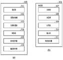
図5は、検査装置109の機能構成を示すブロック図である。検査装置109は、登録部501、読取制御部502、画像処理部503、検査部504、表示制御部505、および搬送制御部506を有する。本実施形態の検査装置109は、検査を行うための処理を行う画像処理装置としても機能する。[Functional configuration of inspection device]
FIG. 5 is a block diagram showing the functional configuration of the
登録部501は、正解画像、データ検査領域等を登録する処理を行う。読取制御部502は、読取部240、241に検査装置109に搬送された用紙の読み取りを実行させて、読取画像の画像データを生成する。画像処理部503は、画像内の特徴点の算出、画像内の座標の変換等の処理を行う。検査部504は、印刷用紙が不良用紙であるかを判定する処理等を行う。表示制御部505は、表示部242等に画面を表示するための制御を行う。搬送制御部506は、検査の結果に応じたトレイに印刷用紙が排紙されるように印刷用紙の搬送を制御する処理を行う。これらの機能の詳細については後述する。 A
また、検査部504は、取得部507、決定部508、合成部509、抽出部510、および検査処理部511を有する。これらの各部の機能の詳細は、後述するフローチャートの説明と合わせて説明する。 The
図5の各部の機能は、検査装置109のCPU238がメモリ239に記憶されているプログラムコードをワークメモリに展開し実行することにより実現される。または、図5の各部の一部または全部の機能をASICや電子回路等のハードウェアで実現してもよい。 5 are implemented by the
[正解画像の登録処理について]
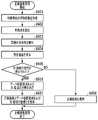
図6は、正解画像の登録の処理の流れを示すフローチャートである。図6のフローチャートで示される一連の処理は、検査装置109のCPUがメモリに記憶されているプログラムコードをワークメモリに展開し実行することにより行われる。また、図6におけるステップの一部または全部の機能をASICや電子回路等のハードウェアで実現してもよい。なお、各処理の説明における記号「S」は、当該フローチャートにおけるステップであることを意味し、以後のフローチャートにおいても同様とする。[Regarding correct image registration processing]
FIG. 6 is a flow chart showing the flow of processing for registering a correct image. A series of processes shown in the flowchart of FIG. 6 are performed by the CPU of the
本フローチャートの開始時において正解画像を生成するための印刷用紙の搬送が実行されたものとして説明する。また、その印刷用紙は、読取部240、241のうちの一方の読取部のみでは印刷用紙の全体を読み取ることができないサイズであるものとして説明する。 A description will be given assuming that the printing paper has been conveyed to generate the correct image at the start of this flowchart. Also, the printing paper will be described as being of a size that cannot be read entirely by only one of the reading
S601において読取制御部502は、読取部240、241に対して検査装置109に搬送された正解画像を生成するための印刷用紙の読み取りを実行させる。本ステップの処理の結果、読取制御部502は、読取部240が印刷用紙の左側を読み取ることで得られた左側の読取画像と、読取部240が印刷用紙の右側を読み取ることで得られた右側の読取画像と、を取得する。2つの読取画像は、メモリ239に保存される。 In step S<b>601 , the
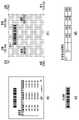
図7は、印刷用紙を読み取ることで生成される正解画像と正解画像内のIDが埋め込まれたコード画像(バーコード)が存在する領域であるID領域とを説明するための図である。図7(a)は、2つの読取画像を合成して得られた合成画像の例を示す図であり、図7(a)の画像が示す印刷用紙が、本ステップで読み取られる。なお、説明の便宜上、本明細書の図では、コード画像であるバーコードを大きく表現しているが、実際は本明細書の図で示した大きさよりも小さい画像となることがある。図7(b)~(d)については後述する。 FIG. 7 is a diagram for explaining a correct image generated by reading a print sheet and an ID area in which a code image (barcode) in which an ID is embedded in the correct image exists. FIG. 7(a) is a diagram showing an example of a composite image obtained by combining two read images, and the printing paper indicated by the image of FIG. 7(a) is read in this step. For convenience of explanation, the drawings in this specification show the bar code, which is a code image, in a large size, but the actual image may be smaller than the size shown in the drawings in this specification. 7B to 7D will be described later.
S602において画像処理部503は、S601の処理の結果得られた2つの読取画像に対して特徴点算出処理を行う。特徴点算出処理では、各種特徴量算出アルゴリズム(Harris Corner DetectionやFast Corner Detection, AKAZE等)に基づいて特徴点を算出する。 In S602, the
S603において合成部509は、S601の処理の結果得られた2つの読取画像を一枚の画像へと合成する合成処理を実行する。 In S<b>603 , the synthesizing
S604において表示制御部505は、表示部242に設定画面を表示する。 In S<b>604 , the
図8は、S604で表示される設定画面の一例を示す図である。図8(a)は、合成画像の生成が完了した後に検査装置109の表示部242に表示される設定画面の一例である。表示領域801は、S603で生成された合成画像を表示する領域である。ボタン802は、データ検査領域の位置情報を設定するための画面に遷移するためのボタンである。データ検査領域とは、前述したように、データ検査の対象となる個別情報が印刷される領域である。 FIG. 8 is a diagram showing an example of the setting screen displayed in S604. FIG. 8A is an example of a setting screen displayed on the
登録ボタン803は、ユーザが表示領域801に表示されている画像を確認した後、正解画像の登録を指示するためのボタンである。登録ボタン803が押下された場合、登録部501は、データ検査領域およびID領域の登録は行わないで、合成画像を正解画像として登録する処理のみを実行する。即ち、データ検査の実行を指示しない場合、ユーザは登録ボタン803を押下する。 A
キャンセルボタン804は、登録処理をキャンセルするためのボタンである。キャンセルボタン804が押下された場合、登録部501は正解画像の登録を行わずに登録処理を終了する。図6のフローチャートでは、キャンセルボタン804は押下されなかった場合について説明する。 A cancel
図8(b)は、ボタン802が押下された後に表示される、データ検査領域を設定するための設定画面の一例を示す図である。位置変更ボタン806は、データ検査領域805の位置を指示するためのボタンである。サイズ変更ボタン807のデータ検査領域805の大きさを指示するためのボタンである。ユーザは、位置変更ボタン806およびサイズ変更ボタン807を操作することで、用紙内のデータ検査領域805の位置およびデータ検査領域805の大きさを指示することができる。 FIG. 8B is a diagram showing an example of a setting screen for setting the data inspection area displayed after the button 802 is pressed. A
ボタン808は、ID領域を設定するための設定画面に遷移するためのボタンである。ID領域とは、前述したように、一次元バーコードまたは二次元バーコード等のコード画像が印刷される領域である。以下の説明では、IDが埋め込まれたコード画像は一次元バーコードであるものとして説明する。 A button 808 is a button for transitioning to a setting screen for setting an ID area. The ID area is an area in which a code image such as a one-dimensional bar code or a two-dimensional bar code is printed, as described above. In the following description, it is assumed that the code image embedded with the ID is a one-dimensional barcode.
図8(c)は、ボタン808が押された後に表示される、ID領域を設定するための設定画面の一例を示す図である。図8(c)の設定画面では、位置変更ボタン806は、ID領域809の位置を指示するため用いられる。また、サイズ変更ボタン807のID領域809の大きさを指示するために用いられる。図8(b)の設定画面と同様に、図8(c)の設定画面では、用紙内のID領域の位置およびID領域の大きさを指定することができる。 FIG. 8(c) is a diagram showing an example of a setting screen for setting the ID area displayed after the button 808 is pressed. In the setting screen of FIG. 8C, a
登録ボタン810は、ユーザが確認した後、ユーザが指定したデータ検査領域およびID領域の位置およびサイズの登録を指示するためのボタンである。登録ボタン810が押下された場合、登録部501は、合成画像を正解画像として登録する。さらに、データ検査領域、およびID領域の登録を行う。 A
なお、用紙に印刷されるIDが埋め込まれたコード画像は一つに限定されないため、ユーザが指定するID領域は一か所に限定されない。データ検査領域も同様である。ボタン811は、複数のデータ検査領域および複数のID領域を指定する場合、未登録のデータ検査領域またはID領域の設定するため設定画面に遷移するためのボタンである。ボタン811が押された場合には、図8(b)の設定画面へ遷移し、ユーザは、未登録のデータ検査領域を設定することができる。さらにボタン808を押下すると未登録のID領域を設定することができる。 Since the number of code images embedded with an ID printed on paper is not limited to one, the ID area specified by the user is not limited to one. The same applies to the data inspection area. A button 811 is a button for transitioning to a setting screen for setting an unregistered data inspection area or ID area when specifying a plurality of data inspection areas and a plurality of ID areas. When the button 811 is pressed, the screen transitions to the setting screen shown in FIG. 8B, and the user can set an unregistered data inspection area. Further, by pressing a button 808, an unregistered ID area can be set.
なお、正解画像を生成するための印刷用紙には実際にコード画像が印刷されていなくてもよいし、仮のコード画像が印刷されていてもよい。全ての用紙に対して共通のコード画像が印刷される場合には、そのコード画像が印刷されていてもよい。 Note that the code image may not actually be printed on the printing paper for generating the correct image, or a temporary code image may be printed. If a code image common to all sheets is printed, the code image may be printed.
図6に戻って登録処理の説明を続ける。S605において登録部501は、ID領域の登録が指示されたかを判定する。即ち、図8(c)の設定画面で登録ボタン810が押下されたかが判定されることになる。ID領域の登録が指示された場合(S605がYES)、S606へ遷移する。 Returning to FIG. 6, the description of the registration process is continued. In S605, the
S606において登録部501は、データ検査領域およびID領域の座標の決定を行う。具体的には、登録部501は、図8(b)および図8(c)の設定画面を介して指定されたデータ検査領域805およびID領域809の位置および大きさに基づき、データ検査領域およびID領域の位置情報である座標を導出する。 In S606, the
図7(a)の画像は、1ページ分の正解画像として登録される合成画像の例である。図7(b)は、図8(c)の設定画面を介して指定された、正解画像内のID領域の位置を示す図である。図7(b)では、灰色下地の領域以外の領域P1―1がID領域として登録されることを表している。領域P1―1は、登録ボタン810またはボタン811が押下された際の図8(c)の表示領域801の正解画像に重畳されたID領域809の位置およびサイズに基づき決定される。図7(c)は、ID領域を正解画像から切り出した有効画像データである。 The image in FIG. 7A is an example of a composite image registered as a correct image for one page. FIG. 7(b) is a diagram showing the position of the ID area in the correct image specified via the setting screen of FIG. 8(c). FIG. 7B shows that the area P1-1 other than the gray background area is registered as the ID area. Area P1-1 is determined based on the position and size of
図7(d)はID領域の位置および大きさを示す位置情報のデータであり、位置情報は、図7(b)の領域P1-1の4隅(左上、右上、左下、右下)の座標の情報である。登録部501は、図8(c)の設定画面で指定されたID領域の位置および大きさを表す4隅の座標を決定する。登録部501は、同様の処理をデータ検査領域についても行う。 FIG. 7(d) shows positional information data indicating the position and size of the ID area. This is coordinate information. The
S607において登録部501は、S606で決定されたデータ検査領域およびID領域の位置情報をメモリ239に保存する。また、S603で生成された合成画像を正解画像としてメモリ239に保存する。複数のID領域の登録が指示された場合、ID領域の個数分、ID領域の位置情報が保存される。 In S<b>607 , the
一方、ID領域の登録が指示されない場合(S605がNO)、S608に遷移する。即ち、図8(a)の設定画面で登録ボタン803が押下された場合、S608に遷移する。S608において登録部501は、合成画像を正解画像としてメモリ239に保存する。 On the other hand, if registration of the ID area is not instructed (NO in S605), the process proceeds to S608. That is, when the
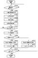
[検査処理について]
図9は検査装置109における検査処理の流れを示すフローチャートである。本フローチャートの説明では、検査対象の印刷用紙は、読取部240、241のうちの一方の読取部のみでは印刷用紙の全体を読み取ることができないサイズであるものとして説明する。また、印刷用紙は、登録済みの正解画像に基づく画像が印刷された用紙であるものとして説明する。[About inspection processing]
FIG. 9 is a flow chart showing the flow of inspection processing in the
検査装置109の読取制御部502は、検査装置109に印刷用紙が搬送されたかを監視しており、S901において読取制御部502は、用紙が搬送されたか判定する。用紙の搬送が検知されると用紙が搬送されたと判定してS902に遷移する。本ステップで検知された用紙を検査対象の用紙とよぶ。 The
S902において読取制御部502は、読取部240、241に対して検査装置109に搬送された検査対象の印刷用紙の読み取りを実行させる。取得部507は、読取部240が検査対象の用紙の左側を読み取ることで得られた左側の読取画像と、読取部240が検査対象の用紙の右側を読み取ることで得られた右側の読取画像と、を取得する。2つの読取画像は、メモリ239に保存される。 In S<b>902 , the
S903では、S902で取得された夫々の読取画像内の座標を正解画像内の座標に合わせる位置合わせ処理を実行する。 In S903, alignment processing is performed to align the coordinates in each read image acquired in S902 with the coordinates in the correct image.
図10は、位置合わせ処理の流れを示すフローチャートである。図10を用いて、S903の処理の詳細を説明する。 FIG. 10 is a flowchart showing the flow of alignment processing. Details of the processing of S903 will be described with reference to FIG.
S1001において画像処理部503は、S902で得られた夫々の読取画像に対して特徴点算出処理を行う。特徴点算出処理では、各種特徴量算出アルゴリズム(Harris Corner DetectionやFast Corner Detection, AKAZE等)に基づいて特徴点を算出する。 In S1001, the
S1002において画像処理部503は、S1001で算出された読取画像の特徴点座標と、S602で算出された正解画像の特徴点座標と、に基づき、読取画像内の座標を正解画像内の座標に合わせるための座標変換用パラメータを算出する。 In S1002, the
S1003において画像処理部503は、S1002で算出された座標変換用パラメータを用いて、読取画像に対して座標変換処理を行う。座標変換処理を行うことで、それぞれの読取画像内の座標は、正解画像に対応する座標に変換される。なお、画像内の座標は、原点が左上で、縦方向がY方向、横方向がX方向に延びる座標系が用いられるものとして説明する。 In S1003, the
図9に戻って検査処理の説明を続ける。S904において検査処理部511は、印刷用紙が不良用紙であるかを決定するための画像検査を行う。本実施形態では、S902で得られた読取画像であって、S903で座標が変換されたそれぞれの読取画像を本ステップの検査のための検査画像として検査を実行するものとして説明する。本ステップで実行される画像検査は、後述するデータ検査とは別の検査である。 Returning to FIG. 9, the description of the inspection process is continued. In S904, the
本ステップの画像検査の方法を説明する。はじめに、画素毎に正解画像と検査画像との画素値の差分値を算出する。そして、差分値の最大値に基づき検査結果の判断を行う。例えば、差分値の最大値が閾値以上であれば検査対象の印刷用紙は不良用紙であると決定する。または、差分値が閾値以上の画素が所定数を超えた場合、不良用紙と決定してもよい。複数の読取部から得られた夫々の読取画像と、正解画像と比較を行う場合は、複数の読取部から得られた全ての読取画像が正解画像と一致するかが判定される。 The image inspection method of this step will be described. First, the difference value between the pixel values of the correct image and the inspection image is calculated for each pixel. Then, the inspection result is determined based on the maximum difference value. For example, if the maximum value of the difference values is equal to or greater than a threshold value, the printing paper to be inspected is determined to be defective paper. Alternatively, when the number of pixels whose difference value is equal to or greater than the threshold exceeds a predetermined number, the paper may be determined as defective. When each read image obtained from a plurality of reading units is compared with the correct image, it is determined whether all the read images obtained from the plurality of reading units match the correct image.
なお、データ検査領域が設定されている場合、本ステップの画像検査では、当該データ検査領域以外の領域の画素の差分値に基づき不良用紙であるかを決定してもよい。または、データ検査領域が設定されている場合は、請求書のようにデータ領域以外にも印刷用紙ごとに異なる文字列が含まれている可能性がある。このためデータ検査領域が設定されている場合、本ステップの画像検査はスキップして、後続のデータ検査処理のみが実行されてもよい。 Note that if a data inspection area is set, in the image inspection of this step, it may be determined whether the sheet is defective based on the difference value of pixels in areas other than the data inspection area. Alternatively, if a data inspection area is set, there is a possibility that different character strings may be included for each print sheet in addition to the data area, such as an invoice. Therefore, when the data inspection area is set, the image inspection in this step may be skipped and only the subsequent data inspection process may be executed.
S905では、S607の処理によってデータ検査領域の位置情報が保存されたかを判定する。データ検査領域が保存されている場合(S905がYES)、S906へ遷移してデータ検査処理が実行される。データ検査領域が保存されていない場合(S905がNO)は、データ検査処理はスキップしてS907へ進む。 In S905, it is determined whether the position information of the data inspection area has been saved by the processing in S607. If the data inspection area is saved (YES in S905), the process proceeds to S906 and data inspection processing is executed. If the data inspection area is not stored (NO in S905), the data inspection process is skipped and the process proceeds to S907.
図11はデータ検査処理の流れを示すフローチャートである。図11を用いてS906で実行されるデータ検査処理の詳細を説明する。 FIG. 11 is a flow chart showing the flow of data inspection processing. Details of the data inspection process executed in S906 will be described with reference to FIG.
S1101において取得部507は、S607の処理の結果、メモリ239に保存された用紙内のデータ画像の位置を表す、ID領域の位置情報(座標)を取得する。 In S<b>1101 , the
S1102において決定部508は、ID領域の位置を示す座標と、S903で位置合わせされた読取画像の座標と、を比較する。そして、決定部508は、比較の結果に基づき、読取部240から得られた読取画像および読取部241から得られた読取画像の何れかが、ID領域の全体が含まれている読取画像であるかを決定する。 In S1102, the
図12は、読取部240、241から得られた読取画像を説明するための図である。図12(a)における読取部240、241の位置はそれぞれの読取部240、241の読取範囲のある位置を示している。即ち、読取部240は印刷用紙の左側を読み取り、読取部241は印刷用紙の右側を読み取るよう配置されていることを示す。また、図12(a)における読取部240、241の幅は、夫々の読取部240、241が読み取ることが可能な最大幅を示している。 12A and 12B are diagrams for explaining read images obtained from the reading
また、読取部240、241は、読取部240の読取範囲と読取部241の読取範囲の重複する領域が存在するように配置されている。読取部240および読取部241の何れもが読み取ることが可能な領域をオーバーラップ領域260とよぶ。オーバーラップ領域260は、読取部241の左端と読取部240右端の間の領域であり、用紙の搬送ずれを考慮して設定されている。 Further, the reading
図12(b)は、読取部240、241によって読み取られる検査対象の印刷用紙1201を示す図である。図12(b)は、印刷用紙1201の左端が、読取部240の読取範囲の左端と一致するように印刷用紙が読み取られることを示している。印刷用紙1201およびID領域の位置および大きさは、図7(b)で示した正解画像の座標と同じであるものとして説明する。 FIG. 12B is a diagram showing a
図12(c)は、読取部240が印刷用紙1201を読み取ることで得られた読取画像1202を示す図である。読取画像1202はID領域であるバーコードのある領域以外の領域の画像は省略して記載している。印刷用紙1201の用紙幅は、読取部240の読取範囲よりも大きな用紙幅をもつ用紙である。このため、印刷用紙1201の左端が、読取部240の読取範囲の左端と一致するように読み取られたが、印刷用紙1201の右側の一部は読み取られないで読取画像1202が生成されたことを示している。読取画像1202の4隅(左上、右上、左下、右下)の座標は、S903の位置合わせ処理の結果得られた正解画像に対応する座標である。 FIG. 12C is a diagram showing a
図12(d)は、読取部241が印刷用紙1201を読み取ることで得られた読取画像1203示す図である。読取画像1203はバーコード以外の画像は省略して記載している。印刷用紙1201の右側が読み取られて読取画像1203が得られたことを示している。読取画像1203の4隅の座標は、S903の位置合わせ処理の結果得られた正解画像に対応する座標である。図12(e)は、読取画像1202、1203のそれぞれの画像内の、左上、右上、左下、右下の4隅の座標値をまとめた表である。 FIG. 12D shows a
図12の場合、読取部240から得られた読取画像1202には、ID領域(バーコード)の全体が含まれている。この場合、S1102において決定部508は、ID領域の全体が含まれている読取画像があると決定する。ID領域の全体が何れかの読取画像内に含まれる場合(S1102がYES)、S1105へ遷移する。 In the case of FIG. 12, the
S1105において抽出部510は、ID領域の全体が含まれる読取画像のID領域から、IDが埋め込まれたコード画像であるバーコードを読み取る。図12の場合、図12(c)の読取画像1202からバーコードを読み取る。このため本実施形態では、合成による画素ズレが発生していない画像から正しいバーコードを読み取ることができる。このため、検査対象の印刷用紙のIDが正しく抽出される。本ステップの処理が完了後、S1106に進む。 In S1105, the
図13は、読取部240、241から得られた読取画像を説明するための図である。図13(a)は、図12(a)と同じ図である。図13(b)は、読取部240、241によって読み取られる印刷用紙1301を示す図である。図13(b)では、搬送の過程で、印刷用紙1301の左端が、読取部240の読取範囲の左端と一致するようには搬送されずに、印刷用紙1301が読み取られることを示している。 13A and 13B are diagrams for explaining read images obtained from the reading
図13(c)は、読取部240が印刷用紙1301を読み取ることで得られた読取画像1302を示す図である。読取画像1302の4隅の座標は、S903の位置合わせ処理の結果得られた正解画像に対応する座標である。図13(d)は、読取部241が印刷用紙1301を読み取ることで得られた読取画像1302を示す図である。印刷用紙1301の右側が読み取られて読取画像1303が得られたことを示している。読取画像1303の4隅の座標は、S903の位置合わせ処理の結果得られた正解画像に対応する座標である。なお、読取画像1302、1303はバーコード以外の画像は省略して記載している。図13(e)は、読取画像1302、1303のそれぞれの4隅の座標値をまとめた表である。 FIG. 13C is a diagram showing a
図13の場合、読取部240から得られた読取画像1302、読取部241から得られた読取画像1303、の何れにもID領域の全体が含まれていない。この場合、S1102において決定部508は、ID領域の全体が含まれている読取画像がないと決定する。ID領域全体が含まれる読取画像が無い場合(S1102がNO)、S1103へ遷移する。 In the case of FIG. 13, neither the
S1103において合成部509は、読取部240から得られた読取画像と読取部241から得られた読取画像を合成して一枚の画像(合成画像)を生成する処理を実行する。 In S1103, the synthesizing
S1104において抽出部510は、S1103で生成された合成画像内のID領域からIDを表すバーコードを読み取る処理を行う。バーコードを読み取ることで検査対象の印刷用紙のIDを抽出する。IDの抽出が完了したらS1106に進む。 In S1104, the
S1106において取得部507は、読取画像のデータ検査領域に印刷されるべき画像(文字列)のデータを取得する。具体的には、初めに印刷用紙を示すIDと個別情報とが対応付けられたデータベースから、検査対象の印刷用紙のIDに対応付けられた個別情報を示す画像(文字列)を取得する。 In S1106, the
図12、図13の印刷用紙のように、例えば、請求書を用紙に印刷する場合であって、個別情報が請求書内の請求額の合計金額を示す文字列である場合、検査対象の印刷用紙に対応した合計金額を示す文字列が取得される。 12 and 13, for example, when an invoice is printed on paper and the individual information is a character string indicating the total billed amount in the invoice, the print to be inspected A character string indicating the total amount corresponding to the paper is obtained.
S1107において検査処理部511は、S1106で取得した個別情報のデータと、読取画像内のデータ検査領域の画像と、を比較する。データ検査領域は、印刷用紙において個別情報が印刷される領域であり、S607の処理によって位置情報が保存されている。例えば、個別情報が文字列である場合は、データ検査領域を文字認識処理して得られた文字列と、S1106で取得した個別情報を示す文字列とを比較する。また、個別情報として画像を取得した場合は、読取画像のデータ検査領域内の画素と、個別情報として取得された画像の画素とを、画素毎に画素値差分を算出してもよい。また、2つの読取画像を合成した合成画像のデータ検査領域のデータと、個別情報のデータを比較して、検査を行ってもよい。 In S1107, the
S1108において検査処理部511は、データ検査の結果、検査対象の印刷用紙が不良用紙か、不良用紙ではない正常用紙か、を決定する。例えば、S1107で文字列を比較した場合、一致しない文字列があれば検査対象の印刷用紙は不良用紙と決定する。または、S1107で画素値を比較した場合、画素値の最大差分値が閾値以上であれば検査対象の印刷用紙は、不良用紙と決定する。不良用紙でない場合、検査処理部511は、検査対象の印刷用紙を正常用紙と決定する。 In S1108, the
図9に戻って検査処理の全体の説明を続ける。S907において検査処理部511は、S904の画像検査およびS906のデータ検査の結果に基づき、検査対象の印刷用紙は正常であるかを判定する。 Returning to FIG. 9, the overall description of the inspection process continues. In S907, the
S904の画像検査およびS906のデータ検査の何れの検査においても不良用紙と決定されなかった場合、本ステップでは正常と判定される。正常の場合はS908へ遷移する。一方、S904の画像検査またはS906のデータ検査の何れかで不良用紙と決定された場合、本ステップでは正常と判定されないで、S910へ遷移する。 If neither the image inspection in S904 nor the data inspection in S906 determines that the sheet is defective, it is determined to be normal in this step. If normal, the process proceeds to S908. On the other hand, if the paper is determined to be defective in either the image inspection in S904 or the data inspection in S906, it is not determined to be normal in this step, and the process proceeds to S910.
正常の場合(S907がYES)、S908において表示制御部505は、検査装置109の表示部242に検査結果がOKであることを表示する。そして、S909に進み、S909において搬送制御部506は、検査対象の印刷用紙が大容量スタッカ110のスタックトレイ341に排紙されるように制御を行う。 If normal (YES in S907), the
正常ではない場合(S907がNO)、S910において表示制御部505は、検査装置109の表示部242に検査結果がNGであることを表示する。そして、S911に進み、S911において搬送制御部506は、検査対象の印刷用紙が大容量スタッカ110のエスケープトレイ346に排紙されるように制御を行う。 If it is not normal (NO in S907), the
なお、S908およびS910において、表示制御部505は、検査結果を、検査装置109の表示部242以外の表示部に表示するように制御をしてもよい。例えば、PC103のディスプレイ205に検査結果が表示されるようにしてよい。 In S908 and S910, the
S912では全ページの検査が完了したかが判定される。全ページの検査が完了していなければ、次ページを検査対象とするためにS901に遷移する。最終ページまで検査が完了していれば処理を終了する。 In S912, it is determined whether inspection of all pages has been completed. If the inspection of all pages has not been completed, the process proceeds to S901 to set the next page to be inspected. If inspection has been completed up to the final page, the process is terminated.
以上説明したように、本実施形態によれば、複数の読取部が印刷用紙を読み取ることで得られた複数の読取画像からIDを抽出する場合でも、正しいIDが抽出できなくなることを抑制することができる。このため、本実施形態によれば印刷用紙の検査の精度を向上させることができる。 As described above, according to the present embodiment, even when extracting IDs from a plurality of read images obtained by reading a printing paper by a plurality of reading units, it is possible to prevent the correct ID from being extracted. can be done. Therefore, according to the present embodiment, it is possible to improve the accuracy of inspection of printing paper.
<実施形態2>
実施形態1における検査処理では、読取部240および読取部241で読み取ることで得られた夫々の読取画像と正解画像とそれぞれ比較する方法を説明した。実施形態2では、読取部240および読取部241で読み取ることで得られた夫々の読取画像を合成して、合成して得られた合成画像と正解画像と比較することで検査をする方法について説明する。<Embodiment 2>
In the inspection process according to the first embodiment, a method of comparing each read image obtained by reading by the
本実施形態では、実施形態1からの差分を中心に説明する。特に明記しない部分については実施形態1と同じ構成および処理である。 In this embodiment, differences from the first embodiment will be mainly described. Parts not specified are the same in configuration and processing as in the first embodiment.
図14は本実施形態の検査処理の流れを示すフローチャートである。S1401~S1402の処理は、S901~S902と同一の処理であるため説明を省略する。また、S1408~S1413の処理は、実施形態1のS907~S912と同一であるため説明を省略する。 FIG. 14 is a flow chart showing the flow of inspection processing in this embodiment. Since the processes of S1401 and S1402 are the same as those of S901 and S902, description thereof will be omitted. Further, since the processing of S1408 to S1413 is the same as that of S907 to S912 of the first embodiment, description thereof is omitted.
本実施形態の検査処理では、位置合わせ処理(S1403)の後、画像検査処理(S1405)およびデータ検査処理(S1407)の前に、S1404では、読取画像を合成する処理が行われる。即ち、S1404では、読取部240および読取部241が検査対象の印刷用紙をそれぞれ読み取って得られた読取画像を一枚の画像へと合成する処理が実行される。 In the inspection process of the present embodiment, after the alignment process (S1403) and before the image inspection process (S1405) and data inspection process (S1407), in S1404, a process of synthesizing the read image is performed. That is, in S1404, a process of synthesizing the read images obtained by reading the printing paper to be inspected by the
図15は画像合成処理の流れを示すフローチャートである。図15を用いてS1404の処理の詳細を説明する。 FIG. 15 is a flow chart showing the flow of image synthesizing processing. Details of the processing of S1404 will be described with reference to FIG.
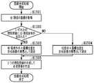
S1501において取得部507は、S607の処理の結果、メモリ239に保存されたID領域の位置情報を取得する。 In S<b>1501 , the
S1502は、実施形態1のデータ検査処理におけるS1102の処理と同様の処理であり、決定部508は、ID領域の全体が含まれている読取画像があるか決定する。ID領域の全体が何れかの読取画像内にある場合(S1502がYES)、S1503へ遷移する。 S1502 is the same processing as S1102 in the data inspection processing of the first embodiment, and the
S1503において合成部509は、読取画像におけるオーバーラップ領域260に対応する領域内で、かつID領域外のX座標位置を、画像合成時の読取画像の境界として設定する。 In S1503, the
図16は、読取部240、241から得られた読取画像を説明するための図である。図16(a)は、図12(a)と同じ図であり読取部240、241の読取範囲を示す図である。図16(b)は、読取部240、241によって読み取られる検査対象の印刷用紙を示す図である。 16A and 16B are diagrams for explaining read images obtained from the reading
図16(c)は、読取部240が印刷用紙を読み取ることで得られた読取画像のサイズを示す図である。図16(d)は、読取部241が印刷用紙を読み取ることで得られた読取画像のサイズを示す図である。図16(c)および(d)の座標値は、S1403の位置合わせ処理の結果、算出された座標値の例である。 FIG. 16(c) is a diagram showing the size of the read image obtained by the
図16(c)の読取画像は、点線の矩形で示したID領域(バーコード)の全体が、画像内に位置している。一方、図16(d)の読取画像は、ID領域(バーコード)の一部のみが、画像内に位置している。このため、図16(b)の印刷用紙を読み取った場合、S1502では、いずれかの読取画像においてID領域の全体が含まれる読取画像があると決定される。 In the read image of FIG. 16(c), the entire ID area (barcode) indicated by a dotted-line rectangle is located within the image. On the other hand, in the read image of FIG. 16(d), only part of the ID area (barcode) is located within the image. Therefore, when the printing paper in FIG. 16B is read, in S1502, it is determined that there is a read image including the entire ID area in any of the read images.
図16(c)~(e)における2点鎖線が示す境界1601は、S1503において設定された境界の例である。読取画像のうちID領域の全体が含まれる読取画像がある場合、S1503では、オーバーラップ領域260内かつID領域外に境界1601のX座標が位置するように境界が設定される。すなわちバーコードの右端のX座標(6000)から読取部240の読取画像の右端のX座標(6500)の間に境界が設定される。このように境界を設定することにより、合成画像におけるID領域内に境界が位置しないように、合成画像が生成される。 A
一方、ID領域の全体が含まれる読取画像が無い場合(S1502がNO)、S1504へ遷移する。S1504において合成部509は、オーバーラップ領域260に対応する画像内のX座標位置を、画像合成時の画像の境界として設定する。 On the other hand, if there is no read image that includes the entire ID area (NO in S1502), the process advances to S1504. In S1504, the
S1505において合成部509は、S1503またはS1504で設定された境界で2つの読取画像がつながるように、読取部240から得られた読取画像と読取部241から得られた読取画像を合成して、一枚の合成画像を生成する。 In S1505, the synthesizing
図16(e)は、図16(c)の読取画像と図16(d)の読取画像とを、境界1601でつながるように合成した結果得られた合成画像を示す図である。このように、境界1601がバーコードのあるID領域に含まれないように合成画像を生成することで、合成による画素ズレが、合成画像におけるID領域で発生することを抑制することができる。 FIG. 16E is a diagram showing a composite image obtained by combining the read image of FIG. 16C and the read image of FIG. In this way, by generating a composite image so that the
図14に戻って、本実施形態の検査処理の説明を続ける。S1405において検査処理部511は、画像検査を実行する。本実施形態の画像検査では、S1404で生成された合成画像を検査画像として、検査画像とメモリ239に記憶されている正解画像と比較することで実行される。 Returning to FIG. 14, the description of the inspection process of this embodiment is continued. In S1405, the
S1406ではS905と同様に、データ検査領域が保存されているか判定する。データ検査領域が保存されている場合、データ検査を実行するためにS1407に進む。 In S1406, similarly to S905, it is determined whether the data inspection area is saved. If the data inspection area is saved, go to S1407 to perform data inspection.
図17は本実施形態のデータ検査処理の流れを示すフローチャートである。図17を用いてS1407の詳細を説明する。なお、本実施形態では、データ検査前に合成画像が生成されているため、データ検査処理において、実施形態1で説明したS1102の決定、S1103の合成画像の生成処理は行われない。 FIG. 17 is a flow chart showing the flow of data inspection processing in this embodiment. Details of S1407 will be described with reference to FIG. Note that in the present embodiment, since the composite image is generated before data inspection, the determination in S1102 and the generation processing of the composite image in S1103 described in the first embodiment are not performed in the data inspection processing.
S1701において抽出部510は、S1404で生成された合成画像内のID領域からIDを抽出する処理を行う。IDの抽出が完了したらS1702に進む。本実施形態の合成画像は、ID領域の全体が含まれている読取画像がある場合、合成画像の境界がID領域に含まれないように合成画像が生成されている。このため、ID領域の全体が含まれている読取画像がある場合、合成画像のID領域には、ID領域の全体が含まれている読取画像におけるID領域の画像が存在することになる。このため、合成画像から正しいIDを抽出することができる。 In S1701, the
S1702~S1704は、S1106~S1108と同様であるため説明を省略する。 Since S1702 to S1704 are the same as S1106 to S1108, description thereof is omitted.
なお、S1703では、抽出されたIDに基づき得られた個別情報のデータと、合成画像のデータ検査領域のデータとが比較される。例えば、個別情報が文字列である場合は、合成画像のデータ検査領域を文字認識処理して得られた文字列と、S1702で取得した個別情報を示す文字列とが比較される。 In S1703, the data of the individual information obtained based on the extracted ID is compared with the data of the data inspection area of the composite image. For example, if the individual information is a character string, the character string obtained by performing character recognition processing on the data inspection area of the synthesized image is compared with the character string representing the individual information acquired in S1702.
以上説明したように、本実施形態によれば、合成時の境界がID領域に位置しないように、読取画像を合成して合成画像を生成することが可能となる。これにより、IDの抽出精度を向上することができる。 As described above, according to the present embodiment, it is possible to generate a composite image by combining read images so that the boundary at the time of composition is not located in the ID area. As a result, the ID extraction accuracy can be improved.
<その他の実施形態>
上記の説明では、コード画像であるバーコードが含まれるID領域が、用紙内に1つ印刷される例を説明したが、印刷用紙には複数のID領域が含まれていてもよい。<Other embodiments>
In the above description, an example was described in which one ID area containing a barcode, which is a code image, is printed on a sheet of paper. However, a plurality of ID areas may be contained on a printing sheet.
図18は、複数のID領域が存在する印刷用紙の例を示す図である。複数のID領域が含まれる印刷用紙の例として、複数の一次元バーコードが存在する場合について説明する。 FIG. 18 is a diagram showing an example of a print sheet having multiple ID areas. A case where a plurality of one-dimensional barcodes are present will be described as an example of printing paper containing a plurality of ID areas.
複数のバーコードが存在する場合、S1404における合成処理において設定される境界は、図18(a)の境界1801ように直線でなくてもよい。即ち、読取部240、241のオーバーラップ領域260内であり、かつバーコードのあるID領域外に境界を設定できればよい。境界は、矩形、または曲線状であってもよい。 If there are multiple barcodes, the boundary set in the synthesizing process in S1404 does not have to be a straight line like the
また、境界をY方向(縦方向)に直線に設定する必要がある場合、図18(b)のように、バーコードの、面積、X座標方向の幅、またはY座標方向の幅等のサイズが小さいバーコード上には境界1802が位置しないように、境界を設定してもよい。例えば、バーコードのパターン幅が小さいほど、画像合成時に発生する画素ズレによってバーコードが適切に読み取ることができなくなることが多くなる。このため、サイズが最も小さいバーコード(ID領域)には境界が含まれないように境界を設定することで、合成画像からバーコード等のコード画像を読み取る精度を向上することができる。 In addition, when the boundary needs to be set straight in the Y direction (vertical direction), as shown in FIG. Boundaries may be set so that the
他にも、複数のコード画像が存在する場合、図18(c)の境界1803ように、境界が重なるバーコードの数が最も少なくなるように境界を設定してもよい。境界が重なるバーコード(ID領域)の個数を減らすことで、画素ズレが発生する可能性があるバーコードの個数を少なくすることができるため、バーコードを読み取る精度を向上することができる。 Alternatively, if there are a plurality of code images, boundaries may be set such that the number of barcodes overlapping the boundaries is minimized, as in the
本発明は、上述の実施形態の1以上の機能を実現するプログラムを、ネットワーク又は記憶媒体を介してシステム又は装置に供給し、そのシステム又は装置のコンピュータにおける1つ以上のプロセッサーがプログラムを読出し実行する処理でも実現可能である。また、1以上の機能を実現する回路(例えば、ASIC)によっても実現可能である。 The present invention supplies a program that implements one or more functions of the above-described embodiments to a system or device via a network or a storage medium, and one or more processors in the computer of the system or device reads and executes the program. It can also be realized by processing to It can also be implemented by a circuit (for example, ASIC) that implements one or more functions.
109 検査装置
238 CPU109
Claims (15)
Translated fromJapanese前記用紙内における前記コード画像の位置および大きさを表す位置情報を取得する第1の取得手段と、
前記用紙内の異なる部分を複数の読取手段がそれぞれ読み取ることで得られた複数の読取画像であって、合成することで前記用紙の全体を表す画像となる複数の読取画像を取得する第2の取得手段と、
前記複数の読取画像のいずれかが、前記コード画像の全体が含まれる読取画像であるかを、前記位置情報に基づき決定する決定手段と、
前記コード画像の全体が含まれる読取画像がある場合、当該読取画像における前記コード画像を読み取って、前記所定の情報を抽出する抽出手段と、
を有することを特徴とする画像処理装置。An image processing device for inspecting a sheet on which a code image encoded with predetermined information is printed,
a first acquisition means for acquiring position information representing the position and size of the code image within the paper;
A second method for obtaining a plurality of read images obtained by reading different portions of the paper by a plurality of reading means, and combining the plurality of read images to form an image representing the entire paper. acquisition means;
determining means for determining, based on the position information, whether any one of the plurality of read images is a read image including the entire code image;
extracting means for extracting the predetermined information by reading the code image in the read image when there is a read image including the entire code image;
An image processing device comprising:
ことを特徴とする請求項1に記載の画像処理装置。2. The image processing apparatus according to claim 1, further comprising synthesizing means for synthesizing the plurality of read images to generate a synthetic image representing the entire sheet.
前記合成手段は前記合成画像を生成し、
前記抽出手段は前記合成画像における前記コード画像を読み取ることで前記所定の情報を抽出する
ことを特徴とする請求項2に記載の画像処理装置。When the determining means determines that there is no read image including the entire code image,
The synthesizing means generates the synthetic image,
3. The image processing apparatus according to claim 2, wherein said extraction means extracts said predetermined information by reading said code image in said synthesized image.
前記設定手段は、前記決定手段が前記コード画像の全体が含まれる読取画像があると決定した場合、前記コード画像に前記境界が含まれないように前記境界を設定し、
前記合成手段は、前記複数の読取画像を前記境界でつながるように合成して、前記合成画像を生成し、
前記抽出手段は、前記合成画像における前記コード画像を読み取ることで前記所定の情報を抽出する
ことを特徴とする請求項2に記載の画像処理装置。further comprising setting means for setting a boundary for generating the composite image;
the setting means sets the boundary such that the code image does not include the boundary when the determining means determines that the read image includes the entire code image;
the synthesizing means synthesizes the plurality of read images so as to connect them at the boundary to generate the synthetic image;
3. The image processing apparatus according to claim 2, wherein said extraction means extracts said predetermined information by reading said code image in said synthesized image.
前記コード画像が前記用紙に複数、含まれる場合、複数の前記コード画像のうち、サイズが最も小さい前記コード画像に前記境界が含まれないように前記境界を設定する
ことを特徴とする請求項4に記載の画像処理装置。The setting means
5. When a plurality of the code images are included in the paper, the boundary is set so that the code image having the smallest size among the plurality of code images does not include the boundary. The image processing device according to .
前記コード画像が前記用紙に複数、含まれる場合、前記境界が含まれる前記コード画像の数が少なくなるように前記境界を設定する
ことを特徴とする請求項4に記載の画像処理装置。The setting means
5. The image processing apparatus according to claim 4, wherein when a plurality of code images are included in the sheet, the boundaries are set so that the number of code images including the boundaries is reduced.
前記読取画像における位置を、前記マスタ画像に対応するように変換する処理をする処理手段と、をさらに有し、
前記決定手段は、
前記読取画像における前記変換された位置に基づき、前記コード画像の全体が含まれる読取画像があるかを決定する
ことを特徴とする請求項1から6のいずれか1項に記載の画像処理装置。registration means for registering a master image as an image corresponding to the sheet to be inspected, and registering the position and size of the code image in the master image as the position information;
further comprising processing means for converting a position in the read image so as to correspond to the master image;
The determining means is
7. The image processing apparatus according to any one of claims 1 to 6, wherein it is determined whether there is a read image including the entire code image based on the converted position in the read image.
前記抽出手段によって抽出された前記所定の情報に基づき前記データ検査領域に対応するデータを取得して、前記データ検査領域に印刷された画像の検査を実行する検査処理手段をさらに有する
ことを特徴とする請求項7に記載の画像処理装置。The registration means registers a data inspection area, which is an area to be inspected in the master image,
The printing apparatus further comprises inspection processing means for acquiring data corresponding to the data inspection area based on the predetermined information extracted by the extraction means, and inspecting the image printed in the data inspection area. 8. The image processing apparatus according to claim 7.
ことを特徴とする請求項1から8のいずれか1項に記載の画像処理装置。9. The method according to any one of claims 1 to 8, further comprising a transport control unit that controls transport of the paper so as to change the destination of the inspected paper based on the result of the inspection. 10. The image processing device according to claim 1.
ことを特徴とする請求項1から9のいずれか1項に記載の画像処理装置。The image processing apparatus according to any one of claims 1 to 9, further comprising display control means for displaying the inspection result on the screen of the display unit.
ことを特徴とする請求項1から10のいずれか1項に記載の画像処理装置。The image processing apparatus according to any one of claims 1 to 10, wherein the code image is a bar code.
ことを特徴とする請求項1から11のいずれか1項に記載の画像処理装置。12. The image processing according to any one of claims 1 to 11, wherein the plurality of reading units are arranged such that there is an area where the reading ranges of the plurality of reading units overlap each other. Device.
請求項1から12のいずれか1項に記載の画像処理装置と、
複数の読取手段と、を有し、
前記印刷装置によって印刷処理された用紙が前記複数の読取手段によって読み取られるように構成されている
ことを特徴とする画像形成装置。a printing device that performs print processing on paper;
an image processing device according to any one of claims 1 to 12;
a plurality of reading means,
An image forming apparatus, wherein a sheet printed by the printing apparatus is read by the plurality of reading units.
前記用紙内における前記コード画像の位置および大きさを表す位置情報を取得する第1の取得ステップと、
前記用紙内の異なる部分を複数の読取手段がそれぞれ読み取ることで得られた複数の読取画像であって、合成することで前記用紙の全体を表す画像となる複数の読取画像を取得する第2の取得ステップと、
前記複数の読取画像のいずれかが、前記コード画像の全体が含まれる読取画像であるかを、前記位置情報に基づき決定する決定ステップと、
前記コード画像の全体が含まれる読取画像がある場合、当該読取画像における前記コード画像を読み取って、前記所定の情報を抽出する抽出ステップと、
を有することを特徴とする画像処理方法。An image processing method for inspecting a sheet on which a code image encoded with predetermined information is printed, comprising:
a first acquisition step of acquiring position information representing the position and size of the code image within the paper;
A second method for obtaining a plurality of read images obtained by reading different portions of the paper by a plurality of reading means, and combining the plurality of read images to form an image representing the entire paper. an acquisition step;
a determination step of determining, based on the position information, whether any one of the plurality of read images is a read image including the entire code image;
an extracting step of, when there is a read image including the entire code image, reading the code image in the read image and extracting the predetermined information;
An image processing method characterized by comprising:
Priority Applications (2)
| Application Number | Priority Date | Filing Date | Title |
|---|---|---|---|
| JP2021078550AJP2022172603A (en) | 2021-05-06 | 2021-05-06 | Image processing apparatus, image forming apparatus, image processing method, and program |
| US17/734,386US11637945B2 (en) | 2021-05-06 | 2022-05-02 | Image processing apparatus, method, and product for identifying and extracting an entire code from a pluraility of read portions of a sheet |
Applications Claiming Priority (1)
| Application Number | Priority Date | Filing Date | Title |
|---|---|---|---|
| JP2021078550AJP2022172603A (en) | 2021-05-06 | 2021-05-06 | Image processing apparatus, image forming apparatus, image processing method, and program |
Publications (1)
| Publication Number | Publication Date |
|---|---|
| JP2022172603Atrue JP2022172603A (en) | 2022-11-17 |
Family
ID=83901805
Family Applications (1)
| Application Number | Title | Priority Date | Filing Date |
|---|---|---|---|
| JP2021078550APendingJP2022172603A (en) | 2021-05-06 | 2021-05-06 | Image processing apparatus, image forming apparatus, image processing method, and program |
Country Status (2)
| Country | Link |
|---|---|
| US (1) | US11637945B2 (en) |
| JP (1) | JP2022172603A (en) |
Family Cites Families (4)
| Publication number | Priority date | Publication date | Assignee | Title |
|---|---|---|---|---|
| JP4113387B2 (en)* | 2002-07-24 | 2008-07-09 | シャープ株式会社 | Portable terminal device, information reading program, and recording medium recording the program |
| JP5310305B2 (en) | 2009-06-26 | 2013-10-09 | 株式会社リコー | Image reading apparatus and image forming apparatus |
| JP2012191252A (en)* | 2011-03-08 | 2012-10-04 | Canon Inc | Apparatus capable of detecting two-dimensional code |
| JP6651837B2 (en)* | 2015-12-22 | 2020-02-19 | 富士ゼロックス株式会社 | Image scanning device, image reading device, and program |
- 2021
- 2021-05-06JPJP2021078550Apatent/JP2022172603A/enactivePending
- 2022
- 2022-05-02USUS17/734,386patent/US11637945B2/enactiveActive
Also Published As
| Publication number | Publication date |
|---|---|
| US20220360683A1 (en) | 2022-11-10 |
| US11637945B2 (en) | 2023-04-25 |
Similar Documents
| Publication | Publication Date | Title |
|---|---|---|
| JP7434020B2 (en) | Inspection device, its control method, and its program | |
| JP7510260B2 (en) | Inspection device, control method thereof, printing system, and program | |
| JP7661550B2 (en) | Image forming apparatus, image forming method, and program | |
| JP7418081B2 (en) | Image forming device, image forming method, and program | |
| JP2021043036A (en) | Inspection device, information processing method and program | |
| JP2023070747A (en) | Image forming device, image forming device control method and program | |
| JP2022011816A (en) | Inspection system, information processing device, control method therefor, and program | |
| JP2024016934A (en) | Image processing device, image processing method and program | |
| JP2021049744A (en) | Image formation device, information processing method and program | |
| JP7471841B2 (en) | Inspection system and method | |
| JP2021182725A (en) | Image processing system and print inspection method and program | |
| JP2021102322A (en) | Image formation apparatus, image formation method, and program | |
| JP2022172603A (en) | Image processing apparatus, image forming apparatus, image processing method, and program | |
| JP7721284B2 (en) | Image processing device and image processing system | |
| JP2023093914A (en) | Image processing device and image processing system | |
| JP2023108683A (en) | Inspection system, printing device, control method of inspection system | |
| JP2023040343A (en) | Printing system, image forming apparatus, control method | |
| JP2023047137A (en) | PRINTING SYSTEM, PRINTING DEVICE, CONTROL METHOD THEREOF, AND PROGRAM | |
| JP2022148533A (en) | Printing system, control method and program thereof | |
| JP2021077937A (en) | Image forming apparatus, information processing method, and program | |
| JP2021115756A (en) | Image forming device, information processing method and program | |
| JP2021123070A (en) | Image formation system | |
| JP7511357B2 (en) | Inspection device, inspection system, inspection system control method, information processing device, and information processing device control method | |
| US11822279B2 (en) | Image forming apparatus, information processing method, printing system, and storage medium for performing reprinting | |
| JP2022161685A (en) | Image forming apparatus and image forming system |