JP2022172132A - Aerosol delivery device including movable cartridge and assembly method related thereto - Google Patents
Aerosol delivery device including movable cartridge and assembly method related theretoDownload PDFInfo
- Publication number
- JP2022172132A JP2022172132AJP2022127723AJP2022127723AJP2022172132AJP 2022172132 AJP2022172132 AJP 2022172132AJP 2022127723 AJP2022127723 AJP 2022127723AJP 2022127723 AJP2022127723 AJP 2022127723AJP 2022172132 AJP2022172132 AJP 2022172132A
- Authority
- JP
- Japan
- Prior art keywords
- cartridge
- housing
- delivery device
- aerosol delivery
- connector
- Prior art date
- Legal status (The legal status is an assumption and is not a legal conclusion. Google has not performed a legal analysis and makes no representation as to the accuracy of the status listed.)
- Pending
Links
Images


Classifications
- A—HUMAN NECESSITIES
- A24—TOBACCO; CIGARS; CIGARETTES; SIMULATED SMOKING DEVICES; SMOKERS' REQUISITES
- A24F—SMOKERS' REQUISITES; MATCH BOXES; SIMULATED SMOKING DEVICES
- A24F40/00—Electrically operated smoking devices; Component parts thereof; Manufacture thereof; Maintenance or testing thereof; Charging means specially adapted therefor
- A24F40/40—Constructional details, e.g. connection of cartridges and battery parts
- A24F40/42—Cartridges or containers for inhalable precursors
- A—HUMAN NECESSITIES
- A24—TOBACCO; CIGARS; CIGARETTES; SIMULATED SMOKING DEVICES; SMOKERS' REQUISITES
- A24F—SMOKERS' REQUISITES; MATCH BOXES; SIMULATED SMOKING DEVICES
- A24F47/00—Smokers' requisites not otherwise provided for
- A—HUMAN NECESSITIES
- A24—TOBACCO; CIGARS; CIGARETTES; SIMULATED SMOKING DEVICES; SMOKERS' REQUISITES
- A24F—SMOKERS' REQUISITES; MATCH BOXES; SIMULATED SMOKING DEVICES
- A24F40/00—Electrically operated smoking devices; Component parts thereof; Manufacture thereof; Maintenance or testing thereof; Charging means specially adapted therefor
- A24F40/90—Arrangements or methods specially adapted for charging batteries thereof
- A24F40/95—Arrangements or methods specially adapted for charging batteries thereof structurally associated with cases
- A—HUMAN NECESSITIES
- A24—TOBACCO; CIGARS; CIGARETTES; SIMULATED SMOKING DEVICES; SMOKERS' REQUISITES
- A24B—MANUFACTURE OR PREPARATION OF TOBACCO FOR SMOKING OR CHEWING; TOBACCO; SNUFF
- A24B15/00—Chemical features or treatment of tobacco; Tobacco substitutes, e.g. in liquid form
- A24B15/10—Chemical features of tobacco products or tobacco substitutes
- A24B15/16—Chemical features of tobacco products or tobacco substitutes of tobacco substitutes
- A24B15/167—Chemical features of tobacco products or tobacco substitutes of tobacco substitutes in liquid or vaporisable form, e.g. liquid compositions for electronic cigarettes
- A—HUMAN NECESSITIES
- A24—TOBACCO; CIGARS; CIGARETTES; SIMULATED SMOKING DEVICES; SMOKERS' REQUISITES
- A24B—MANUFACTURE OR PREPARATION OF TOBACCO FOR SMOKING OR CHEWING; TOBACCO; SNUFF
- A24B15/00—Chemical features or treatment of tobacco; Tobacco substitutes, e.g. in liquid form
- A24B15/18—Treatment of tobacco products or tobacco substitutes
- A24B15/24—Treatment of tobacco products or tobacco substitutes by extraction; Tobacco extracts
- A24B15/241—Extraction of specific substances
- A24B15/243—Nicotine
- A—HUMAN NECESSITIES
- A24—TOBACCO; CIGARS; CIGARETTES; SIMULATED SMOKING DEVICES; SMOKERS' REQUISITES
- A24B—MANUFACTURE OR PREPARATION OF TOBACCO FOR SMOKING OR CHEWING; TOBACCO; SNUFF
- A24B15/00—Chemical features or treatment of tobacco; Tobacco substitutes, e.g. in liquid form
- A24B15/18—Treatment of tobacco products or tobacco substitutes
- A24B15/28—Treatment of tobacco products or tobacco substitutes by chemical substances
- A24B15/30—Treatment of tobacco products or tobacco substitutes by chemical substances by organic substances
- A24B15/32—Treatment of tobacco products or tobacco substitutes by chemical substances by organic substances by acyclic compounds
- A—HUMAN NECESSITIES
- A24—TOBACCO; CIGARS; CIGARETTES; SIMULATED SMOKING DEVICES; SMOKERS' REQUISITES
- A24F—SMOKERS' REQUISITES; MATCH BOXES; SIMULATED SMOKING DEVICES
- A24F15/00—Receptacles or boxes specially adapted for cigars, cigarettes, simulated smoking devices or cigarettes therefor
- A24F15/01—Receptacles or boxes specially adapted for cigars, cigarettes, simulated smoking devices or cigarettes therefor specially adapted for simulated smoking devices or cigarettes therefor
- A—HUMAN NECESSITIES
- A24—TOBACCO; CIGARS; CIGARETTES; SIMULATED SMOKING DEVICES; SMOKERS' REQUISITES
- A24F—SMOKERS' REQUISITES; MATCH BOXES; SIMULATED SMOKING DEVICES
- A24F40/00—Electrically operated smoking devices; Component parts thereof; Manufacture thereof; Maintenance or testing thereof; Charging means specially adapted therefor
- A24F40/20—Devices using solid inhalable precursors
- A—HUMAN NECESSITIES
- A24—TOBACCO; CIGARS; CIGARETTES; SIMULATED SMOKING DEVICES; SMOKERS' REQUISITES
- A24F—SMOKERS' REQUISITES; MATCH BOXES; SIMULATED SMOKING DEVICES
- A24F40/00—Electrically operated smoking devices; Component parts thereof; Manufacture thereof; Maintenance or testing thereof; Charging means specially adapted therefor
- A24F40/40—Constructional details, e.g. connection of cartridges and battery parts
- A24F40/46—Shape or structure of electric heating means
- A—HUMAN NECESSITIES
- A24—TOBACCO; CIGARS; CIGARETTES; SIMULATED SMOKING DEVICES; SMOKERS' REQUISITES
- A24F—SMOKERS' REQUISITES; MATCH BOXES; SIMULATED SMOKING DEVICES
- A24F40/00—Electrically operated smoking devices; Component parts thereof; Manufacture thereof; Maintenance or testing thereof; Charging means specially adapted therefor
- A24F40/40—Constructional details, e.g. connection of cartridges and battery parts
- A24F40/48—Fluid transfer means, e.g. pumps
- A—HUMAN NECESSITIES
- A24—TOBACCO; CIGARS; CIGARETTES; SIMULATED SMOKING DEVICES; SMOKERS' REQUISITES
- A24F—SMOKERS' REQUISITES; MATCH BOXES; SIMULATED SMOKING DEVICES
- A24F40/00—Electrically operated smoking devices; Component parts thereof; Manufacture thereof; Maintenance or testing thereof; Charging means specially adapted therefor
- A24F40/50—Control or monitoring
- A24F40/51—Arrangement of sensors
- A—HUMAN NECESSITIES
- A24—TOBACCO; CIGARS; CIGARETTES; SIMULATED SMOKING DEVICES; SMOKERS' REQUISITES
- A24F—SMOKERS' REQUISITES; MATCH BOXES; SIMULATED SMOKING DEVICES
- A24F40/00—Electrically operated smoking devices; Component parts thereof; Manufacture thereof; Maintenance or testing thereof; Charging means specially adapted therefor
- A24F40/60—Devices with integrated user interfaces
- A—HUMAN NECESSITIES
- A24—TOBACCO; CIGARS; CIGARETTES; SIMULATED SMOKING DEVICES; SMOKERS' REQUISITES
- A24F—SMOKERS' REQUISITES; MATCH BOXES; SIMULATED SMOKING DEVICES
- A24F40/00—Electrically operated smoking devices; Component parts thereof; Manufacture thereof; Maintenance or testing thereof; Charging means specially adapted therefor
- A24F40/65—Devices with integrated communication means, e.g. wireless communication means
- A—HUMAN NECESSITIES
- A24—TOBACCO; CIGARS; CIGARETTES; SIMULATED SMOKING DEVICES; SMOKERS' REQUISITES
- A24F—SMOKERS' REQUISITES; MATCH BOXES; SIMULATED SMOKING DEVICES
- A24F7/00—Mouthpieces for pipes; Mouthpieces for cigar or cigarette holders
- A24F7/02—Mouthpieces for pipes; Mouthpieces for cigar or cigarette holders with detachable connecting members
- A—HUMAN NECESSITIES
- A45—HAND OR TRAVELLING ARTICLES
- A45C—PURSES; LUGGAGE; HAND CARRIED BAGS
- A45C13/00—Details; Accessories
- A45C13/16—Closures of the roller-blind type
- A—HUMAN NECESSITIES
- A61—MEDICAL OR VETERINARY SCIENCE; HYGIENE
- A61M—DEVICES FOR INTRODUCING MEDIA INTO, OR ONTO, THE BODY; DEVICES FOR TRANSDUCING BODY MEDIA OR FOR TAKING MEDIA FROM THE BODY; DEVICES FOR PRODUCING OR ENDING SLEEP OR STUPOR
- A61M15/00—Inhalators
- A61M15/06—Inhaling appliances shaped like cigars, cigarettes or pipes
- H—ELECTRICITY
- H05—ELECTRIC TECHNIQUES NOT OTHERWISE PROVIDED FOR
- H05B—ELECTRIC HEATING; ELECTRIC LIGHT SOURCES NOT OTHERWISE PROVIDED FOR; CIRCUIT ARRANGEMENTS FOR ELECTRIC LIGHT SOURCES, IN GENERAL
- H05B3/00—Ohmic-resistance heating
- H05B3/68—Heating arrangements specially adapted for cooking plates or analogous hot-plates
- H05B3/74—Non-metallic plates, e.g. vitroceramic, ceramic or glassceramic hobs, also including power or control circuits
- H05B3/748—Resistive heating elements, i.e. heating elements exposed to the air, e.g. coil wire heater
- A—HUMAN NECESSITIES
- A24—TOBACCO; CIGARS; CIGARETTES; SIMULATED SMOKING DEVICES; SMOKERS' REQUISITES
- A24F—SMOKERS' REQUISITES; MATCH BOXES; SIMULATED SMOKING DEVICES
- A24F40/00—Electrically operated smoking devices; Component parts thereof; Manufacture thereof; Maintenance or testing thereof; Charging means specially adapted therefor
- A24F40/10—Devices using liquid inhalable precursors
Landscapes
- Engineering & Computer Science (AREA)
- Health & Medical Sciences (AREA)
- Chemical & Material Sciences (AREA)
- General Chemical & Material Sciences (AREA)
- Chemical Kinetics & Catalysis (AREA)
- General Health & Medical Sciences (AREA)
- Veterinary Medicine (AREA)
- Anesthesiology (AREA)
- Life Sciences & Earth Sciences (AREA)
- Animal Behavior & Ethology (AREA)
- Biomedical Technology (AREA)
- Public Health (AREA)
- Hematology (AREA)
- Pulmonology (AREA)
- Heart & Thoracic Surgery (AREA)
- Bioinformatics & Cheminformatics (AREA)
- Human Computer Interaction (AREA)
- Computer Networks & Wireless Communication (AREA)
- Toxicology (AREA)
- Ceramic Engineering (AREA)
- Containers And Packaging Bodies Having A Special Means To Remove Contents (AREA)
Abstract
Description
Translated fromJapanese本開示は、エアロゾル送達デバイスに関し、より具体的には、分離した筐体に対して、複数の構成間を可動であるカートリッジを含むエアロゾル送達デバイスに関する。本エアロゾル送達デバイスは、エアロゾル前駆体を加熱するように構成された加熱要素を備える噴霧器を含む。タバコから作製される、またはそれに由来する、あるいはタバコを組み込む構成要素を含み得るエアロゾル前駆体組成物は、噴霧器によって加熱され、ヒトによる消費のための吸入可能な物質を生み出す。 FIELD OF THE DISCLOSURE The present disclosure relates to aerosol delivery devices and, more particularly, to aerosol delivery devices that include cartridges movable between multiple configurations relative to separate housings. The aerosol delivery device includes a nebulizer with a heating element configured to heat the aerosol precursor. The aerosol precursor composition, which may be made from or derived from tobacco or contain tobacco-incorporating components, is heated by a nebulizer to produce an inhalable substance for human consumption.
多くの喫煙デバイスが、使用のためにタバコの燃焼を必要とする喫煙製品に対する改良案または代替案として、長年にわたり提案されてきた。これらのデバイスの多くは、紙巻きタバコ、葉巻、またはパイプ喫煙に関連する知覚を、タバコの燃焼に起因する相当量の不完全燃焼及び熱分解生成物を送達することなく、提供するように意図的に設計されてきた。このために、電気エネルギーを利用して、揮発性材料を蒸発させるかまたは加熱する、あるいはタバコをかなりの程度燃焼させることなく、紙巻きタバコ、葉巻、またはパイプ喫煙の知覚を提供することを試みる、多数の喫煙製品、風味生成器、及び医療用吸入器が提案されてきた。例えば、参照によりその全体が本明細書に組み込まれる、Griffith Jr.らの米国特許出願公開第2013/0255702号、Sebastianらの米国特許出願公開第2014/0000638号、Collettらの米国特許出願公開第2014/0060554号、Searsらの米国特許出願公開第2014/0096781号、2013年3月14日出願のAmpoliniらの米国特許出願第13/826,929号、2013年8月28日出願のDavisらの米国特許出願第14/011,992号に記載される背景技術において示される、様々な代替の喫煙物品、エアロゾル送達デバイス、及び熱生成源を参照されたい。また、例えば、参照によりその全体が本明細書に組み込まれる、Countsらの米国特許第5,388,594号、及びRobinsonらの同第8,079,371号の背景技術項に記載される、製品及び加熱構成の様々な実施形態も参照されたい。 Many smoking devices have been proposed over the years as improvements or alternatives to smoking products that require the combustion of tobacco for use. Many of these devices are designed to provide the sensation associated with cigarette, cigar, or pipe smoking without delivering appreciable amounts of incomplete combustion and thermal decomposition products resulting from tobacco combustion. has been designed to To this end, attempts are made to utilize electrical energy to vaporize or heat volatile materials, or to provide the perception of cigarettes, cigars, or pipe smoking without burning the tobacco to any appreciable extent. A number of smoking products, flavor generators and medical inhalers have been proposed. For example, Griffith Jr., incorporated herein by reference in its entirety. U.S. Patent Application Publication No. 2013/0255702 to Sebastian et al., U.S. Patent Application Publication No. 2014/0000638 to Collett et al., U.S. Patent Application Publication No. 2014/0060554 to Collett et al. , U.S. Patent Application No. 13/826,929 to Ampolini et al., filed March 14, 2013, and U.S. Patent Application No. 14/011,992 to Davis et al. See various alternative smoking articles, aerosol delivery devices, and heat generating sources presented in. Also, for example, in the background section of Counts et al., U.S. Pat. No. 5,388,594 and Robinson et al., U.S. Pat. See also various embodiments of products and heating configurations.
エアロゾル送達デバイスの特定の既存の実施形態は、制御体とカートリッジとを含む。電源(例えば、電池)は制御体内に位置付けられ得、エアロゾル前駆体組成物はカートリッジ内に位置付けられ得る。カートリッジ及び制御体は互いに係合し、細長い管状構成を画定し得る。しかしながら、特定の他のエアロゾル送達デバイスの形状要素が望ましい場合もある。 Certain existing embodiments of aerosol delivery devices include a control body and a cartridge. A power source (eg, a battery) can be positioned within the control body and the aerosol precursor composition can be positioned within the cartridge. The cartridge and control body may engage each other to define an elongated tubular configuration. However, certain other aerosol delivery device form factors may be desirable.
本開示は、特定の実施形態では、電子タバコとして特徴づけられ得るエアロゾル送達デバイスに関する。 The present disclosure relates, in certain embodiments, to aerosol delivery devices that can be characterized as electronic cigarettes.
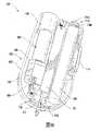
一態様において、エアロゾル送達デバイスが提供される。エアロゾル送達デバイスは、噴霧器と、エアロゾル前駆体組成物を収容するように構成された貯蔵器と、筐体と、吸い口を備えるカートリッジとを含み得る。筐体は、制御体とも称され得、いくつかの実施形態では、カートリッジは筐体に解放可能に連結され得る。カートリッジは、筐体の少なくとも一部分に対して、吸い口が露出する延出した構成と、吸い口が延出した構成よりも筐体と相対的に近い後退した構成との間で可動であり得る。 In one aspect, an aerosol delivery device is provided. An aerosol delivery device may include a nebulizer, a reservoir configured to contain an aerosol precursor composition, a housing, and a cartridge with a mouthpiece. The housing may also be referred to as a control, and in some embodiments the cartridge may be releasably coupled to the housing. The cartridge may be movable with respect to at least a portion of the housing between an extended configuration in which the mouthpiece is exposed and a retracted configuration in which the mouthpiece is relatively closer to the housing than in the extended configuration. .
いくつかの実施形態では、カートリッジは貯蔵器を含み得る。さらに、カートリッジは噴霧器を含み得る。カートリッジは交換可能であり得る。エアロゾル送達デバイスは、カートリッジに連結され、延出した構成と後退した構成との間でカートリッジを移動させるように構成された作動装置を追加で含み得る。 In some embodiments, a cartridge can include a reservoir. Additionally, the cartridge may include a nebulizer. Cartridges may be replaceable. The aerosol delivery device may additionally include an actuator coupled to the cartridge and configured to move the cartridge between an extended configuration and a retracted configuration.
いくつかの実施形態では、作動装置は滑動部を含み得る。滑動部は、カートリッジが後退した構成にあるとき、筐体内に画定される開口部を覆い、それによりカートリッジが筐体内に実質的に封入されるように構成され得、延出した構成において、開口部の少なくとも一部分から後退し、カートリッジが開口部を通って延出することを可能にするようにさらに構成され得る。作動装置は、ばねとボタンとを含み得る。ばねは、ボタンの作動に際し、後退した構成から延出した構成へカートリッジを移動させるように構成され得る。 In some embodiments, the actuator can include a slide. The sled may be configured to cover an opening defined within the housing when the cartridge is in the retracted configuration, thereby substantially enclosing the cartridge within the housing; It may be further configured to be recessed from at least a portion of the portion to allow the cartridge to extend through the opening. The actuator may include a spring and button. The spring may be configured to move the cartridge from the retracted configuration to the extended configuration upon actuation of the button.
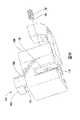
筐体は、主本体部分と枢動可能に接続された可動部分を含み得る。作動装置は、可動部分が開く間に、後退した構成から延出した構成へカートリッジを移動させるように構成され、可動部分が閉じる間に、延出した構成から後退した構成へカートリッジを移動させるように構成された接続機構を含み得る。カートリッジは、筐体に対して枢動するように構成され得る。カートリッジは、筐体の主本体部分に対して静止したままであるように構成され得る。吸い口は、後退した構成において筐体の内側に位置付けられ得る。 The housing may include a movable portion pivotally connected with the main body portion. The actuator is configured to move the cartridge from the retracted configuration to the extended configuration during opening of the movable portion and to move the cartridge from the extended configuration to the retracted configuration during closing of the movable portion. may include a connection mechanism configured to . The cartridge may be configured to pivot with respect to the housing. The cartridge may be configured to remain stationary with respect to the main body portion of the housing. The mouthpiece may be positioned inside the housing in a retracted configuration.
追加の態様において、エアロゾル送達デバイスを組み立てる方法が提供される。本方法は、噴霧器と、エアロゾル前駆体組成物を収容するように構成された貯蔵器と、筐体と、吸い口を備えるカートリッジとを提供することと、噴霧器をカートリッジまたは筐体内に位置付けることと、貯蔵器をカートリッジまたは筐体内に位置付けることと、カートリッジが、筐体の少なくとも一部分に対して、吸い口が露出する延出した構成と、吸い口が延出した構成よりも筐体と相対的に近い後退した構成との間で可動であるようにカートリッジを筐体に動作的に係合することとを含み得る。 In an additional aspect, a method of assembling an aerosol delivery device is provided. The method comprises providing a nebulizer, a reservoir configured to contain an aerosol precursor composition, a housing, a cartridge comprising a mouthpiece, and positioning the nebulizer within the cartridge or housing. positioning the reservoir within the cartridge or housing; and the cartridge relative to at least a portion of the housing in an extended configuration with the mouthpiece exposed and relative to the housing rather than the mouthpiece extended configuration. operably engaging the cartridge with the housing so as to be moveable between a retracted configuration near the .
いくつかの実施形態では、貯蔵器をカートリッジまたは筐体内に位置付けることは、貯蔵器をカートリッジ内に位置付けることを含み得る。噴霧器をカートリッジまたは筐体内に位置付けることは、噴霧器をカートリッジ内に位置付けることを含み得る。カートリッジを筐体に動作的に係合することは、カートリッジを作動装置と連結することを含み得る。作動装置は、延出した構成と後退した構成との間でカートリッジを移動させるように構成され得る。カートリッジを作動装置と連結することは、滑動部を筐体内に少なくとも部分的に挿入することを含み得る。滑動部は、後退した構成において筐体内の開口部を覆い、それによりカートリッジが筐体内に実質的に封入されるように構成され得、延出した構成において開口部の少なくとも一部分から後退し、カートリッジが開口部を通って延出することを可能にするようにさらに構成され得る。本方法は、筐体の主本体部分を筐体の可動部分に枢動可能に連結することを追加で含み得る。カートリッジを筐体に動作的に係合することは、カートリッジを筐体に枢動可能に連結することを含み得る。 In some embodiments, positioning the reservoir within the cartridge or housing may include positioning the reservoir within the cartridge. Positioning the nebulizer within the cartridge or housing may include positioning the nebulizer within the cartridge. Operationally engaging the cartridge with the housing may include coupling the cartridge with an actuator. The actuator may be configured to move the cartridge between an extended configuration and a retracted configuration. Coupling the cartridge with the actuator may include inserting the sled at least partially into the housing. The sled may be configured to cover the opening in the housing in a retracted configuration, thereby substantially enclosing the cartridge within the housing, and retracted from at least a portion of the opening in the extended configuration, the cartridge extend through the opening. The method may additionally include pivotally coupling the main body portion of the housing to the movable portion of the housing. Operationally engaging the cartridge with the housing may include pivotally coupling the cartridge to the housing.
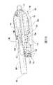
追加の態様において、エアロゾル送達デバイスが提供される。エアロゾル送達デバイスは、筐体と、噴霧器及びエアロゾル前駆体組成物を収容する貯蔵器を備えるカートリッジに係合するように構成された連結器を備える接続器と、筐体内に少なくとも部分的に受容され接続器に係合した作動装置とを含み得、作動装置は、筐体の少なくとも一部分に対して、延出した構成と後退した構成との間でカートリッジを移動させるように構成される。 In an additional aspect, an aerosol delivery device is provided. The aerosol delivery device comprises a housing, a connector comprising a connector configured to engage a cartridge comprising a nebulizer and a reservoir containing an aerosol precursor composition, and at least partially received within the housing. an actuator engaged with the connector, the actuator configured to move the cartridge between an extended configuration and a retracted configuration relative to at least a portion of the housing.
いくつかの実施形態では、エアロゾル送達デバイスは電源を追加で含み得る。エアロゾル送達デバイスは、制御器をさらに含み得る。制御器は、電力を電源からカートリッジへと向け、噴霧器を用いて貯蔵器に保持されたエアロゾル前駆体組成物を加熱し、エアロゾルを生み出すように構成され得る。作動装置は、トラック上を滑動するように構成された滑動部を含み得る。作動装置は、滑動部を移動させるためのユーザによる係合のために構成された外部係合部材を追加で含み得る。 In some embodiments, the aerosol delivery device can additionally include a power source. The aerosol delivery device can further include a controller. The controller can be configured to direct power from the power source to the cartridge to heat the aerosol precursor composition held in the reservoir with the nebulizer to produce an aerosol. The actuator may include a slide configured to slide on the track. The actuator may additionally include an external engagement member configured for engagement by a user to move the slide.
追加の態様において、エアロゾル送達デバイスを組み立てる方法が提供される。本方法は、筐体と、作動装置と、噴霧器及びエアロゾル前駆体組成物を収容する貯蔵器を備えるカートリッジに係合するように構成された連結器を備える接続器とを提供することと、接続器を作動装置と連結することと、作動装置が筐体の少なくとも一部分に対して延出した構成と後退した構成との間でカートリッジを移動させるように構成されるように接続器及び作動装置を筐体内に少なくとも部分的に挿入することとを含み得る。 In an additional aspect, a method of assembling an aerosol delivery device is provided. The method includes providing a housing, an actuator, and a connector comprising a connector configured to engage a cartridge comprising a nebulizer and a reservoir containing an aerosol precursor composition; and connecting the connector and actuator such that the actuator is configured to move the cartridge between an extended configuration and a retracted configuration relative to at least a portion of the housing. and inserting at least partially within the housing.
いくつかの実施形態では、本方法は、電源を筐体内に挿入することを追加で含み得る。さらに、本方法は、制御器を筐体内に挿入することを含み得る。制御器は、電力を電源からカートリッジへと向け、噴霧器を用いて貯蔵器に保持されたエアロゾル前駆体組成物を加熱し、エアロゾルを生み出すように構成され得る。本方法は、作動装置を組み立てることを追加で含み得る。作動装置を組み立てることは、滑動部をトラックに係合することを含み得る。作動装置を組み立てることは、外部係合部材を滑動部と連結することをさらに含み得る。外部係合部材は、滑動部を移動させるためのユーザによる係合のために構成され得る。 In some embodiments, the method may additionally include inserting the power source into the housing. Additionally, the method may include inserting the controller into the housing. The controller can be configured to direct power from the power source to the cartridge to heat the aerosol precursor composition held in the reservoir with the nebulizer to produce an aerosol. The method may additionally include assembling the actuator. Assembling the actuator may include engaging the slide with the track. Assembling the actuator may further include coupling the external engagement member with the slide. The external engagement member may be configured for engagement by a user to move the slide.
追加の実施形態では、エアロゾル送達デバイスが提供される。エアロゾル送達デバイスは、筐体と、筐体内の電源と、筐体に可動に取り付けられた接続器と、吸い口を有する外側本体を備えカートリッジとを含み得、吸い口はそれを通したエアロゾルの通過のために構成される。カートリッジは、筐体の少なくとも一部分に対して可動であるように、接続器に係合し得る。 In additional embodiments, an aerosol delivery device is provided. The aerosol delivery device may include a housing, a power source within the housing, a connector movably attached to the housing, and a cartridge with an outer body having a mouthpiece, the mouthpiece for directing the aerosol therethrough. Configured for transit. The cartridge may engage the connector so as to be movable relative to at least a portion of the housing.
いくつかの実施形態では、カートリッジは、エアロゾル前駆体組成物を保持するように構成された貯蔵器を含み得る。カートリッジは噴霧器を含み得る。カートリッジは、接続器に取り外し可能に係合され得、かつ交換可能であり得る。 In some embodiments, a cartridge can include a reservoir configured to hold an aerosol precursor composition. The cartridge may contain an atomizer. The cartridge can be removably engaged with the connector and can be replaceable.
いくつかの実施形態では、エアロゾル送達デバイスは、接続器に連結され、吸い口が露出する延出した構成と、吸い口が延出した構成よりも筐体と相対的に近い後退した構成との間でカートリッジを移動させるように構成された作動装置を追加で含み得る。作動装置は滑動部を含み得る。滑動部は、カートリッジが後退した構成にあるとき、筐体内に画定される開口部を覆い、それによりカートリッジが筐体内に実質的に封入されるように構成され得、延出した構成において、開口部の少なくとも一部分から後退し、カートリッジが開口部を通って延出することを可能にするようにさらに構成され得る。作動装置は、ばねとボタンとを含み得る。ばねは、ボタンの作動に際し、後退した構成から延出した構成へカートリッジを移動させるように構成され得る。 In some embodiments, the aerosol delivery device is coupled to the connector and has an extended configuration with the mouthpiece exposed and a retracted configuration with the mouthpiece relatively closer to the housing than the extended configuration. An actuator configured to move the cartridge therebetween may additionally be included. The actuator may include a slide. The sled may be configured to cover an opening defined within the housing when the cartridge is in the retracted configuration, thereby substantially enclosing the cartridge within the housing; It may be further configured to be recessed from at least a portion of the portion to allow the cartridge to extend through the opening. The actuator may include a spring and button. The spring may be configured to move the cartridge from the retracted configuration to the extended configuration upon actuation of the button.
いくつかの実施形態では、筐体は、主本体部分と枢動可能に接続された可動部分を含み得る。作動装置は、可動部分が開く間に、後退した構成から延出した構成へカートリッジを移動させるように構成され、可動部分が閉じる間に、延出した構成から後退した構成へカートリッジを移動させるように構成された接続機構を含み得る。カートリッジは、筐体に対して枢動するように構成され得る。吸い口は、後退した構成において筐体の内側に位置付けられ得る。 In some embodiments, the housing can include a movable portion pivotally connected to the main body portion. The actuator is configured to move the cartridge from the retracted configuration to the extended configuration during opening of the movable portion and to move the cartridge from the extended configuration to the retracted configuration during closing of the movable portion. may include a connection mechanism configured to The cartridge may be configured to pivot with respect to the housing. The mouthpiece may be positioned inside the housing in a retracted configuration.
追加の実施形態では、エアロゾル送達デバイスが提供される。エアロゾル送達デバイスは、吸い口を有する外側本体を含むカートリッジであって、吸い口がそれを通したエアロゾルの通過のために構成されているカートリッジと、主本体部分及び可動部分を含む筐体と、筐体内の電源とを含み得る。筐体の可動部分は、筐体の主本体部分に対して、カートリッジの吸い口が露出する第1の位置と、吸い口が筐体の可動部分内に少なくとも部分的に受容される第2の位置との間で移動するように構成され得る。 In additional embodiments, an aerosol delivery device is provided. The aerosol delivery device is a cartridge including an outer body having a mouthpiece, the mouthpiece configured for passage of an aerosol therethrough; a housing including a main body portion and a movable portion; and a power source within the enclosure. The movable portion of the housing is positioned relative to the main body portion of the housing in a first position in which the mouthpiece of the cartridge is exposed and in a second position in which the mouthpiece is at least partially received within the movable portion of the housing. can be configured to move between positions.
いくつかの実施形態では、カートリッジは、筐体の主本体部分に対して静止したままであるように構成され得る。筐体の可動部分は、筐体の主本体部分に向かって及びそこから離れて平行移動するように構成され得る。筐体の可動部分は、筐体の主本体部分に対して枢動するように構成され得る。 In some embodiments, the cartridge may be configured to remain stationary with respect to the main body portion of the housing. The movable portion of the housing may be configured to translate toward and away from the main body portion of the housing. The movable portion of the housing may be configured to pivot with respect to the main body portion of the housing.
いくつかの実施形態では、エアロゾル送達デバイスは、筐体に取り付けられ、カートリッジに係合した接続器をさらに含み得る。接続器は、筐体の主本体部分に固定して取り付けられ得る。カートリッジは、接続器に取り外し可能に係合され得、かつ交換可能であり得る。カートリッジは噴霧器を含み得る。 In some embodiments, the aerosol delivery device can further include a connector attached to the housing and engaged with the cartridge. The connector may be fixedly attached to the main body portion of the housing. The cartridge can be removably engaged with the connector and can be replaceable. The cartridge may contain an atomizer.
追加の実施形態では、エアロゾル送達デバイスを組み立てる方法が提供される。本方法は、筐体と、電源と、吸い口を有する外側本体を備えるカートリッジに係合するように構成された接続器とを提供することを含み得、吸い口はそれを通したエアロゾルの通過のために構成される。本方法は、電源を筐体内に位置付けることと、接続器が筐体の少なくとも一部分に対してカートリッジを移動させるように構成されるように接続器を筐体に可動に取り付けることとを追加で含み得る。 In additional embodiments, methods of assembling an aerosol delivery device are provided. The method may include providing a housing, a power source, and a connector configured to engage a cartridge comprising an outer body having a mouthpiece, the mouthpiece for the passage of an aerosol therethrough. configured for The method additionally includes positioning the power source within the housing and movably mounting the connector to the housing such that the connector is configured to move the cartridge relative to at least a portion of the housing. obtain.
いくつかの実施形態では、本方法は、カートリッジを接続器に係合することを追加で含み得る。本方法は、接続器を作動装置と連結することをさらに含み得る。作動装置は、延出した構成と後退した構成との間でカートリッジを移動させるように構成され得る。加えて、本方法は、作動装置を組み立てることを含み得る。作動装置を組み立てることは、滑動部をトラックに係合することを含み得る。作動装置を組み立てることは、外部係合部材を滑動部と連結することを追加で含み得る。外部係合部材は、滑動部を移動させるためのユーザによる係合のために構成され得る。 In some embodiments, the method can additionally include engaging the cartridge with the connector. The method may further include coupling the connector with the actuator. The actuator may be configured to move the cartridge between an extended configuration and a retracted configuration. Additionally, the method may include assembling the actuator. Assembling the actuator may include engaging the slide with the track. Assembling the actuator may additionally include coupling the external engagement member with the slide. The external engagement member may be configured for engagement by a user to move the slide.
本発明は、以下の実施形態を含むが、これらに限定されない。 The invention includes, but is not limited to, the following embodiments.
実施形態1:エアロゾル送達デバイスであって、
筐体と、
筐体内の電源と、
筐体に可動に取り付けられた接続器と、
吸い口を有する外側本体を備えるカートリッジと、を備え、吸い口がそれを通したエアロゾルの通過のために構成され、カートリッジが筐体の少なくとも一部分に対して可動であるように接続器に係合されている、エアロゾル送達デバイス。Embodiment 1: An aerosol delivery device comprising
a housing;
a power supply inside the enclosure;
a connector movably attached to the housing;
a cartridge comprising an outer body having a mouthpiece configured for passage of an aerosol therethrough and engaging the connector such that the cartridge is movable relative to at least a portion of the housing. an aerosol delivery device.
実施形態2:カートリッジが、エアロゾル前駆体組成物を保持するように構成された貯蔵器を備える、前述または後述の実施形態のいずれかに記載のエアロゾル送達デバイス。 Embodiment 2: The aerosol delivery device of any preceding or following embodiment, wherein the cartridge comprises a reservoir configured to hold an aerosol precursor composition.
実施形態3:カートリッジが噴霧器を備える、前述または後述の実施形態のいずれかに記載のエアロゾル送達デバイス。 Embodiment 3: An aerosol delivery device according to any preceding or subsequent embodiment, wherein the cartridge comprises a nebulizer.
実施形態4:カートリッジが、接続器に取り外し可能に係合し、かつ交換可能である、前述または後述の実施形態のいずれかに記載のエアロゾル送達デバイス。 Embodiment 4: An aerosol delivery device according to any preceding or subsequent embodiment, wherein the cartridge is removably engageable with the connector and is replaceable.
実施形態5:接続器に連結され、吸い口が露出する延出した構成と、吸い口が延出した構成よりも筐体と相対的に近い後退した構成との間でカートリッジを移動させるように構成された作動装置をさらに備える、前述または後述の実施形態のいずれかに記載のエアロゾル送達デバイス。 Embodiment 5: Connected to a connector to move the cartridge between an extended configuration with the mouthpiece exposed and a retracted configuration where the mouthpiece is closer relative to the housing than the extended configuration An aerosol delivery device according to any preceding or subsequent embodiment, further comprising a configured actuator.
実施形態6:作動装置が滑動部を備える、前述または後述の実施形態のいずれかに記載のエアロゾル送達デバイス。 Embodiment 6: An aerosol delivery device according to any preceding or subsequent embodiment, wherein the actuator comprises a slide.
実施形態7:滑動部が、カートリッジが後退した構成にあるとき、筐体内に画定される開口部を覆い、それによりカートリッジが筐体内に実質的に封入されるように構成され、延出した構成において開口部の少なくとも一部分から後退し、カートリッジが開口部を通って延出することを可能にするようにさらに構成されている、前述または後述の実施形態のいずれかに記載のエアロゾル送達デバイス。 Embodiment 7: An extended configuration configured such that the sled covers an opening defined within the housing when the cartridge is in the retracted configuration, thereby substantially enclosing the cartridge within the housing An aerosol delivery device according to any of the preceding or following embodiments, further configured to be retracted from at least a portion of the opening in at to allow the cartridge to extend through the opening.
実施形態8:作動装置が、ばねとボタンとを備え、ばねが、ボタンの作動に際し、後退した構成から延出した構成へカートリッジを移動させるように構成されている、前述または後述の実施形態のいずれかに記載のエアロゾル送達デバイス。 Embodiment 8: Of any preceding or following embodiment, wherein the actuator comprises a spring and a button, the spring configured to move the cartridge from a retracted configuration to an extended configuration upon actuation of the button. An aerosol delivery device according to any one.
実施形態9:筐体が、主本体部分と枢動可能に接続される可動部分を備え、
作動装置が、可動部分が開く間に、後退した構成から延出した構成へカートリッジを移動させるように構成され、可動部分が閉じる間に、延出した構成から後退した構成へカートリッジを移動させるように構成された接続機構を備える、前述または後述の実施形態のいずれかに記載のエアロゾル送達デバイス。Embodiment 9: The housing comprises a movable portion pivotally connected to the main body portion,
The actuator is configured to move the cartridge from the retracted configuration to the extended configuration during opening of the movable portion and to move the cartridge from the extended configuration to the retracted configuration during closing of the movable portion. An aerosol delivery device according to any preceding or following embodiment, comprising a connection mechanism configured to:
実施形態10:カートリッジが筐体に対して枢動するように構成されている、前述または後述の実施形態のいずれかに記載のエアロゾル送達デバイス。 Embodiment 10: The aerosol delivery device of any preceding or subsequent embodiment, wherein the cartridge is configured to pivot with respect to the housing.
実施形態11:吸い口が、後退した構成において筐体の内側に位置付けられる、前述または後述の実施形態のいずれかに記載のエアロゾル送達デバイス。 Embodiment 11: An aerosol delivery device according to any preceding or subsequent embodiment, wherein the mouthpiece is positioned inside the housing in a retracted configuration.
実施形態12:エアロゾル送達デバイスであって、
吸い口を有する外側本体を備え、吸い口がそれを通したエアロゾルの通過のために構成されている、カートリッジと、
主本体部分と可動部分とを備える筐体と、
筐体内の電源と、を備え、
筐体の可動部分が、筐体の主本体部分に対して、カートリッジの吸い口が露出する第1の位置と、吸い口が筐体の可動部分内に少なくとも部分的に受容される第2の位置との間で移動するように構成されている、エアロゾル送達デバイス。Embodiment 12: An aerosol delivery device comprising
a cartridge comprising an outer body having a mouthpiece, the mouthpiece configured for passage of an aerosol therethrough;
a housing comprising a main body portion and a movable portion;
a power source within the enclosure;
The movable portion of the housing is positioned relative to the main body portion of the housing in a first position in which the mouthpiece of the cartridge is exposed and in a second position in which the mouthpiece is at least partially received within the movable portion of the housing. An aerosol delivery device configured to move between positions.
実施形態13:カートリッジが、筐体の主本体部分に対して静止したままであるように構成されている、前述または後述の実施形態のいずれかに記載のエアロゾル送達デバイス。 Embodiment 13: An aerosol delivery device according to any preceding or subsequent embodiment, wherein the cartridge is configured to remain stationary with respect to the main body portion of the housing.
実施形態14:筐体の可動部分が、筐体の主本体部分に向かって及びそこから離れて平行移動するように構成されている、前述または後述の実施形態のいずれかに記載のエアロゾル送達デバイス。 Embodiment 14: An aerosol delivery device according to any preceding or subsequent embodiment, wherein the movable portion of the housing is configured to translate toward and away from the main body portion of the housing. .
実施形態15:筐体の可動部分が、筐体の主本体部分に対して枢動するように構成されている、前述または後述の実施形態のいずれかに記載のエアロゾル送達デバイス。 Embodiment 15: An aerosol delivery device according to any preceding or subsequent embodiment, wherein the movable portion of the housing is configured to pivot with respect to the main body portion of the housing.
実施形態16:筐体に取り付けられ、カートリッジに係合される接続器をさらに備える、前述または後述の実施形態のいずれかに記載のエアロゾル送達デバイス。 Embodiment 16: The aerosol delivery device of any preceding or following embodiment, further comprising a connector attached to the housing and engaged with the cartridge.
実施形態17:接続器が、筐体の主本体部分に固定して取り付けられている、前述または後述の実施形態のいずれかに記載のエアロゾル送達デバイス。 Embodiment 17: An aerosol delivery device according to any preceding or subsequent embodiment, wherein the connector is fixedly attached to the main body portion of the housing.
実施形態18:カートリッジが、接続器に取り外し可能に係合し、かつ交換可能である、前述または後述の実施形態のいずれかに記載のエアロゾル送達デバイス。 Embodiment 18: An aerosol delivery device according to any preceding or subsequent embodiment, wherein the cartridge is removably engaged with the connector and is replaceable.
実施形態19:カートリッジが噴霧器を備える、前述または後述の実施形態のいずれかに記載のエアロゾル送達デバイス。 Embodiment 19: An aerosol delivery device according to any preceding or subsequent embodiment, wherein the cartridge comprises a nebulizer.
実施形態20: エアロゾル送達デバイスであって、
筐体と、
噴霧器及びエアロゾル前駆体組成物を収容する貯蔵器を備えるカートリッジに係合するように構成された連結器を備える接続器と、
筐体内に少なくとも部分的に受容され、接続器に係合した作動装置と、を備え、作動装置が、筐体の少なくとも一部分に対して、延出した構成と後退した構成との間でカートリッジを移動させるように構成されている、エアロゾル送達デバイス。Embodiment 20: An aerosol delivery device comprising
a housing;
a connector comprising a connector configured to engage a nebulizer and a cartridge comprising a reservoir containing an aerosol precursor composition;
an actuator at least partially received within the housing and engaged with the connector, the actuator moving the cartridge between an extended configuration and a retracted configuration with respect to at least a portion of the housing. An aerosol delivery device configured for locomotion.
実施形態21:電源をさらに備える、前述または後述の実施形態のいずれかに記載のエアロゾル送達デバイス。 Embodiment 21: The aerosol delivery device of any preceding or following embodiment, further comprising a power source.
実施形態22:制御器をさらに備え、
制御器が、電力を電源からカートリッジへと向け、噴霧器を用いて貯蔵器に保持されたエアロゾル前駆体組成物を加熱し、エアロゾルを生み出すように構成されている、前述または後述の実施形態のいずれかに記載のエアロゾル送達デバイス。Embodiment 22: Further comprising a controller,
Any of the preceding or following embodiments, wherein the controller is configured to direct power from the power source to the cartridge to heat the aerosol precursor composition held in the reservoir with the nebulizer to produce the aerosol. an aerosol delivery device according to any one of the preceding paragraphs.
実施形態23:作動装置が、トラック上を滑動するように構成された滑動部を備える、前述または後述の実施形態のいずれかに記載のエアロゾル送達デバイス。 Embodiment 23: An aerosol delivery device according to any preceding or subsequent embodiment, wherein the actuator comprises a slide configured to slide on a track.
実施形態24:作動装置が、滑動部を移動させるためのユーザによる係合のために構成された外部係合部材をさらに備える、前述または後述の実施形態のいずれかに記載のエアロゾル送達デバイス。 Embodiment 24: An aerosol delivery device according to any preceding or subsequent embodiment, wherein the actuator further comprises an external engagement member configured for engagement by a user to move the slide.
実施形態25:エアロゾル送達デバイスを組み立てる方法であって、
筐体と、電源と、吸い口を有する外側本体を備えるカートリッジに係合するように構成された接続器であって、吸い口がそれを通したエアロゾルの通過のために構成されている、接続器とを提供することと、
電源を筐体内に位置付けることと、
接続器が筐体の少なくとも一部分に対してカートリッジを移動させるように構成されるように接続器を筐体に可動に取り付けることと、を含む方法。Embodiment 25: A method of assembling an aerosol delivery device, comprising:
A connector configured to engage a cartridge comprising a housing, a power source, and an outer body having a mouthpiece, the mouthpiece configured for passage of an aerosol therethrough. providing a vessel;
positioning the power supply within the enclosure;
movably mounting the connector to the housing such that the connector is configured to move the cartridge relative to at least a portion of the housing.
実施形態26:カートリッジを接続器に係合することをさらに含む、前述または後述の実施形態のいずれかに記載の方法。 Embodiment 26: The method of any preceding or following embodiment, further comprising engaging the cartridge with the connector.
実施形態27:接続器を作動装置と連結することをさらに含み、作動装置が、延出した構成と後退した構成との間でカートリッジを移動させるように構成されている、前述または後述の実施形態のいずれかに記載の方法。 Embodiment 27: Any preceding or following embodiment further comprising coupling a connector with an actuator, wherein the actuator is configured to move the cartridge between an extended configuration and a retracted configuration The method according to any one of
実施形態28:作動装置を組み立てることをさらに含み、作動装置を組み立てることが、滑動部をトラックに係合することを含む、前述または後述の実施形態のいずれかに記載の方法。 Embodiment 28: The method of any preceding or following embodiment, further comprising assembling the actuator, wherein assembling the actuator comprises engaging the slide with the track.
実施形態29:作動装置を組み立てることが、外部係合部材を滑動部と連結することをさらに含み、外部係合部材が、滑動部を移動させるためのユーザによる係合のために構成されている、前述または後述の実施形態のいずれかに記載の方法。 Embodiment 29: Assembling the actuator further comprises coupling an external engagement member with the slide, the external engagement member configured for engagement by a user to move the slide , a method according to any of the preceding or following embodiments.
実施形態30:エアロゾル送達デバイスであって、
筐体と、
電源と、
筐体の少なくとも一部分に対して可動である接続器と、を備え、
接続器が、筐体の少なくとも一部分に対して可動であるように、吸い口を有する外側本体を備えるカートリッジに係合するように構成され、吸い口が、それを通したエアロゾルの通過のために構成されている、エアロゾル送達デバイス。Embodiment 30: An aerosol delivery device comprising
a housing;
a power supply;
a connector movable relative to at least a portion of the housing;
A connector is configured to engage a cartridge comprising an outer body having a mouthpiece so as to be movable relative to at least a portion of the housing, the mouthpiece for passage of an aerosol therethrough. an aerosol delivery device, comprising:
実施形態31:カートリッジをさらに備える、前述または後述の実施形態のいずれかに記載のエアロゾル送達デバイス。 Embodiment 31: The aerosol delivery device of any preceding or following embodiment, further comprising a cartridge.
実施形態32:カートリッジが、エアロゾル前駆体組成物を保持するように構成された貯蔵器を備える、前述または後述の実施形態のいずれかに記載のエアロゾル送達デバイス。 Embodiment 32: An aerosol delivery device according to any preceding or subsequent embodiment, wherein the cartridge comprises a reservoir configured to hold an aerosol precursor composition.
実施形態33:カートリッジが噴霧器を備える、前述または後述の実施形態のいずれかに記載のエアロゾル送達デバイス。 Embodiment 33: An aerosol delivery device according to any preceding or subsequent embodiment, wherein the cartridge comprises a nebulizer.
実施形態34:カートリッジが、接続器に取り外し可能に係合し、かつ交換可能である、前述または後述の実施形態のいずれかに記載のエアロゾル送達デバイス。 Embodiment 34: An aerosol delivery device according to any preceding or subsequent embodiment, wherein the cartridge is removably engageable with the connector and is replaceable.
実施形態35:制御器をさらに備え、
制御器が、電力を電源からカートリッジへと向け、噴霧器を用いて貯蔵器に保持されたエアロゾル前駆体組成物を加熱し、エアロゾルを生み出すように構成されている、前述または後述の実施形態のいずれかに記載のエアロゾル送達デバイス。Embodiment 35: Further comprising a controller,
Any of the preceding or following embodiments, wherein the controller is configured to direct power from the power source to the cartridge to heat the aerosol precursor composition held in the reservoir with the nebulizer to produce the aerosol. an aerosol delivery device according to any one of the preceding paragraphs.
実施形態36:電源が筐体内に位置付けられている、前述または後述の実施形態のいずれかに記載のエアロゾル送達デバイス。 Embodiment 36: An aerosol delivery device according to any preceding or subsequent embodiment, wherein the power source is located within the housing.
実施形態37:接続器に連結され、吸い口が露出する延出した構成と、吸い口が延出した構成よりも筐体と相対的に近い後退した構成との間でカートリッジを移動させるように構成された作動装置をさらに備える、請求項1~7のいずれか一項に記載のエアロゾル送達デバイス。 Embodiment 37: Coupled to a connector to move the cartridge between an extended configuration with the mouthpiece exposed and a retracted configuration where the mouthpiece is closer relative to the housing than the extended configuration The aerosol delivery device of any one of claims 1-7, further comprising a configured actuator.
実施形態38:作動装置が滑動部を備える、前述または後述の実施形態のいずれかに記載のエアロゾル送達デバイス。 Embodiment 38: An aerosol delivery device according to any preceding or subsequent embodiment, wherein the actuator comprises a slide.
実施形態39:滑動部が、カートリッジが後退した構成にあるとき、筐体内に画定された開口部を覆い、それによりカートリッジが筐体内に実質的に封入されるように構成され、延出した構成において開口部の少なくとも一部分から後退し、カートリッジが開口部を通って延出することを可能にするようにさらに構成されている、前述または後述の実施形態のいずれかに記載のエアロゾル送達デバイス。 Embodiment 39: An extended configuration configured such that the sled covers an opening defined within the housing when the cartridge is in the retracted configuration, thereby substantially enclosing the cartridge within the housing An aerosol delivery device according to any of the preceding or following embodiments, further configured to be retracted from at least a portion of the opening in at to allow the cartridge to extend through the opening.
実施形態40:作動装置が、ばねとボタンとを備え、ばねが、ボタンの作動に際し、後退した構成から延出した構成へカートリッジを移動させるように構成されている、前述または後述の実施形態のいずれかに記載のエアロゾル送達デバイス。 Embodiment 40: Of any preceding or following embodiment, wherein the actuator comprises a spring and a button, the spring configured to move the cartridge from a retracted configuration to an extended configuration upon actuation of the button. An aerosol delivery device according to any one.
実施形態41:筐体が、主本体部分と枢動可能に接続される可動部分を備え、
作動装置が、可動部分が開く間に、後退した構成から延出した構成へカートリッジを移動させるように構成され、可動部分が閉じる間に、延出した構成から後退した構成へカートリッジを移動させるように構成された接続機構を備える、前述または後述の実施形態のいずれかに記載のエアロゾル送達デバイス。Embodiment 41: The housing comprises a movable portion pivotally connected to the main body portion,
The actuator is configured to move the cartridge from the retracted configuration to the extended configuration during opening of the movable portion and to move the cartridge from the extended configuration to the retracted configuration during closing of the movable portion. An aerosol delivery device according to any preceding or following embodiment, comprising a connection mechanism configured to:
実施形態42:吸い口が、後退した構成において筐体の内側に位置付けられる、前述または後述の実施形態のいずれかに記載のエアロゾル送達デバイス。 Embodiment 42: An aerosol delivery device according to any preceding or subsequent embodiment, wherein the mouthpiece is positioned inside the housing in a retracted configuration.
実施形態43:カートリッジが、筐体に対して枢動するように構成されている、前述または後述の実施形態のいずれかのうちの1つに記載のエアロゾル送達デバイス。 Embodiment 43: An aerosol delivery device according to any one of the preceding or following embodiments, wherein the cartridge is configured to pivot with respect to the housing.
実施形態44:筐体が、主本体部分と可動部分とを備え、
筐体の可動部分が、筐体の主本体部分に対して、カートリッジの吸い口が露出する第1の位置と、吸い口が筐体の可動部分内に少なくとも部分的に受容される第2の位置との間で移動するように構成されている、前述または後述の実施形態のいずれかのうちの1つに記載のエアロゾル送達デバイス。Embodiment 44: The housing comprises a main body portion and a movable portion,
The movable portion of the housing is positioned relative to the main body portion of the housing in a first position in which the mouthpiece of the cartridge is exposed and in a second position in which the mouthpiece is at least partially received within the movable portion of the housing. An aerosol delivery device according to any one of the preceding or following embodiments, configured to move between positions.
実施形態45:カートリッジが、筐体の主本体部分に対して静止したままであるように構成されている、前述または後述の実施形態のいずれかに記載のエアロゾル送達デバイス。 Embodiment 45: An aerosol delivery device according to any preceding or subsequent embodiment, wherein the cartridge is configured to remain stationary with respect to the main body portion of the housing.
実施形態46:筐体の可動部分が、筐体の主本体部分に向かって及びそこから離れて平行移動するように構成されている、前述または後述の実施形態のいずれかに記載のエアロゾル送達デバイス。 Embodiment 46: An aerosol delivery device according to any preceding or subsequent embodiment, wherein the movable portion of the housing is configured to translate toward and away from the main body portion of the housing. .
実施形態47:筐体の可動部分が、筐体の主本体部分に対して枢動するように構成されている、前述または後述の実施形態のいずれかに記載のエアロゾル送達デバイス。 Embodiment 47: An aerosol delivery device according to any preceding or subsequent embodiment, wherein the movable portion of the housing is configured to pivot with respect to the main body portion of the housing.
実施形態48:接続器が、筐体の主本体部分に固定して取り付けられている、前述または後述の実施形態のいずれかに記載のエアロゾル送達デバイス。 Embodiment 48: An aerosol delivery device according to any preceding or subsequent embodiment, wherein the connector is fixedly attached to the main body portion of the housing.
実施形態49:筐体内に少なくとも部分的に受容され、接続器に係合した作動装置をさらに備え、作動装置が、筐体の少なくとも一部分に対して、延出した構成と後退した構成との間でカートリッジを移動させるように構成され、
接続器が、カートリッジに係合するように構成された連結器を備える、前述または後述の実施形態のいずれかのうちの1つに記載のエアロゾル送達デバイス。Embodiment 49: Further comprising an actuator at least partially received within the housing and engaged with the connector, the actuator being between an extended configuration and a retracted configuration with respect to at least a portion of the housing is configured to move the cartridge with
An aerosol delivery device according to any one of the preceding or following embodiments, wherein the connector comprises a connector configured to engage the cartridge.
実施形態50:作動装置が、トラック上を滑動するように構成された滑動部を備える、前述または後述の実施形態のいずれかに記載のエアロゾル送達デバイス。 Embodiment 50: An aerosol delivery device according to any preceding or subsequent embodiment, wherein the actuator comprises a slide configured to slide on a track.
実施形態51:作動装置が、滑動部を移動させるためのユーザによる係合のために構成された外部係合部材をさらに備える、前述または後述の実施形態のいずれかに記載のエアロゾル送達デバイス。 Embodiment 51: An aerosol delivery device according to any preceding or subsequent embodiment, wherein the actuator further comprises an external engagement member configured for engagement by a user to move the slide.
実施形態52: エアロゾル送達デバイスを組み立てる方法であって、
筐体と、電源と、吸い口を有する外側本体を備えるカートリッジに係合するように構成された接続器であって、吸い口がそれを通したエアロゾルの通過のために構成されている、接続器とを提供することと、
電源を筐体内に位置付けることと、
接続器が筐体の少なくとも一部分に対してカートリッジを移動させるように構成されるように接続器を筐体に可動に取り付けることと、を含む方法。Embodiment 52: A method of assembling an aerosol delivery device comprising:
A connector configured to engage a cartridge comprising a housing, a power source, and an outer body having a mouthpiece, the mouthpiece configured for passage of an aerosol therethrough. providing a vessel;
positioning the power supply within the enclosure;
movably mounting the connector to the housing such that the connector is configured to move the cartridge relative to at least a portion of the housing.
実施形態53:カートリッジを接続器に係合することをさらに含む、前述または後述の実施形態のいずれかに記載の方法。 Embodiment 53: The method of any preceding or following embodiment, further comprising engaging the cartridge with the connector.
実施形態54:接続器を作動装置と連結することをさらに含み、作動装置が、延出した構成と後退した構成との間でカートリッジを移動させるように構成されている、前述または後述の実施形態のいずれかに記載の方法。 Embodiment 54: Any preceding or following embodiment further comprising coupling a connector with an actuator, the actuator configured to move the cartridge between an extended configuration and a retracted configuration The method according to any one of
実施形態55:作動装置を組み立てることをさらに含み、作動装置を組み立てることが、滑動部をトラックに係合することを含む、前述または後述の実施形態のいずれかに記載の方法。 Embodiment 55: The method of any preceding or following embodiment, further comprising assembling the actuator, wherein assembling the actuator comprises engaging the slide with the track.
実施形態56:作動装置を組み立てることが、外部係合部材を滑動部と連結することをさらに含み、外部係合部材が、滑動部を移動させるためのユーザによる係合のために構成されている、前述または後述の実施形態のいずれかに記載の方法。 Embodiment 56: Assembling the actuator further comprises coupling an external engagement member with the slide, the external engagement member configured for engagement by a user to move the slide , a method according to any of the preceding or following embodiments.
本開示のこれら及び他の特徴、態様、及び利点は、以下で簡単に説明する添付の図面と併せて以下の発明を実施するための形態を読むことから明らかとなるであろう。本発明は、上述の実施形態のうちの2つ、3つ、4つ、またはそれ以上の任意の組み合わせ、及び本開示に示す任意の2つ、3つ、4つ、またはそれ以上の特徴または要素の組み合わせを含み、これは、かかる特徴または要素が、本明細書の特定の実施形態の説明において明示的に組み合わされるか否かにかかわらない。この開示は、開示される発明のいずれの分離可能な特徴または要素も、その様々な態様及び実施形態のいずれにおいても、文脈上そうではないことが明確に示されない限り、組み合わせ可能であることが意図されるものとして見られるべきであるように、総合的に読まれることが意図される。 These and other features, aspects, and advantages of the present disclosure will become apparent from a reading of the following detailed description in conjunction with the accompanying drawings, which are briefly described below. The present invention includes any combination of any two, three, four or more of the above embodiments and any two, three, four or more features or features shown in this disclosure. It includes combinations of elements, regardless of whether such features or elements are explicitly combined in the description of a particular embodiment herein. This disclosure indicates that any separable feature or element of the disclosed invention, in any of its various aspects and embodiments, is combinable unless the context clearly dictates otherwise. It is intended to be read comprehensively as it should be viewed as intended.
本開示を上述の一般用語で説明しているが、必ずしも原寸に比例して描写されていない添付の図面をこれから参照する。 Having described the present disclosure in the foregoing general terms, reference is now made to the accompanying drawings, which are not necessarily drawn to scale.
本開示は、これからその例示的な実施形態を参照しながら以下でより完全に説明される。これらの例示的な実施形態は、本開示が徹底的及び完全であるように、また当業者に本開示の範囲を十分に伝えるように説明する。実際に、本開示は、多くの異なる形態で具現化され得、本明細書に示される実施形態に限定されるものと解釈されるべきではなく、むしろ、これらの実施形態は、本開示が適用される法的要件を満たすように提供される。本明細書及び添付の特許請求の範囲で使用する場合、単数形「1つの(a)」、「1つの(an)」、「その(the)」は、文脈がそうではないことを明確に示さない限り、複数形変形を含む。 The disclosure will now be described more fully below with reference to exemplary embodiments thereof. These exemplary embodiments are provided so that this disclosure will be thorough and complete, and will fully convey the scope of the disclosure to those skilled in the art. Indeed, this disclosure may be embodied in many different forms and should not be construed as limited to the embodiments set forth herein, but rather those embodiments may be applied to the present disclosure. provided to meet legal requirements. As used in this specification and the appended claims, the singular forms "a," "an," and "the" clearly dispense with the context. Including plural variations unless indicated.
本開示に従うエアロゾル送達デバイスは、材料を加熱して(好ましくは、材料をかなりの程度燃焼させることなく)、吸入可能な物質を形成するために、電気エネルギーを使用し得、かかる物品は、「手持ち式」デバイスと見なすのに十分に小型であることが最も好ましい。エアロゾル送達デバイスは、その物品またはデバイスのいかなる構成要素のいかなる相当程度の燃焼もなく紙巻きタバコ、葉巻、またはパイプを喫煙することの知覚(例えば、吸入及び発散習慣、味または風味の種類、感覚刺激性効果、身体的感覚、使用習慣、可視のエアロゾルによって提供されるものなどの視覚的刺激、ならびに同様のもの)の一部または全てを提供し得る。エアロゾル送達デバイスは、タバコの燃焼または熱分解の副生成物に起因するエアロゾルという意味の煙を生み出すのではなく、むしろ、物品またはデバイスは、他の実施形態ではエアロゾルは可視でない場合もあるが、物品またはデバイスのある特定の構成要素の揮発または気化に起因する蒸気(煙様として説明されると見なされてもよい可視のエアロゾルと見なされ得るエアロゾル中の蒸気を含む)を最も好ましくもたらし得る。極めて好ましい実施形態では、エアロゾル送達デバイスは、タバコ及び/またはタバコ由来の構成要素を組み込み得る。このように、エアロゾル送達デバイスは、電子タバコなどの電子喫煙物品として特徴づけることができる。 An aerosol delivery device according to the present disclosure may use electrical energy to heat a material (preferably without burning the material to any appreciable extent) to form an inhalable substance; Most preferably, it is small enough to be considered a "hand-held" device. Aerosol delivery devices can reduce the perception of smoking a cigarette, cigar, or pipe without any appreciable burning of any component of the article or device (e.g., inhalation and exhalation habits, taste or flavor type, sensory stimulation). sexual effects, physical sensations, habits of use, visual stimuli such as those provided by visible aerosols, and the like). The aerosol delivery device does not produce smoke in the sense of an aerosol resulting from tobacco combustion or pyrolysis by-products; Most preferably, it may result in vapors (including vapors in aerosols, which may be considered visible aerosols, which may be described as smoke-like) resulting from volatilization or vaporization of certain components of the article or device. In highly preferred embodiments, the aerosol delivery device may incorporate tobacco and/or tobacco-derived components. As such, the aerosol delivery device can be characterized as an electronic smoking article, such as an electronic cigarette.
本開示のエアロゾル送達デバイスはまた、蒸気産出物品または薬剤送達物品であることを特徴とし得る。故に、かかる物品またはデバイスは、1つ以上の物質(例えば、風味及び/または薬学的活性成分)を吸入可能な形態または状態で提供するように適合させることができる。例えば、吸入可能な物質は、実質的に蒸気の形態(すなわち、その臨界点より低い温度での気相中にある物質)であり得る。あるいは、吸入可能な物質は、エアロゾルの形態(すなわち、ガス中の固体微粒子または液滴の浮遊物)であり得る。簡潔性を目的として、用語「エアロゾル」は、本明細書で使用する場合、可視であるか否か、かつ煙様と見なされ得る形態であるか否かにかかわらず、ヒトの吸入に好適な形態または種類の蒸気、ガス、及びエアロゾルを含むことを意味する。 Aerosol delivery devices of the present disclosure can also be characterized as vapor producing articles or drug delivery articles. Such articles or devices may thus be adapted to provide one or more substances (eg, flavors and/or pharmaceutically active ingredients) in inhalable form or condition. For example, the inhalable substance may be substantially in vapor form (ie, the substance in the gas phase at a temperature below its critical point). Alternatively, the inhalable substance may be in the form of an aerosol (ie, a suspension of solid particles or droplets in a gas). For the sake of brevity, the term "aerosol", as used herein, is suitable for human inhalation, whether visible or not and in a form that can be considered smoke-like. It is meant to include forms or types of vapors, gases, and aerosols.
使用中、本開示のエアロゾル送達デバイスは、伝統的な種類の喫煙物品(例えば、タバコに点火し吸入することによって用いられる紙巻きタバコ、葉巻、またはパイプ)の使用において個人が用いる物理的行為の多くに供され得る。例えば、本開示のエアロゾル送達デバイスは、ユーザによって手持ちされること、ユーザがその物品によって生み出されるエアロゾルを吸引するためにその物品の一部分を吸うこと、ユーザが選択された間隔で吹かすこと、及び同様のことなどが可能である。 In use, the aerosol delivery device of the present disclosure replaces many of the physical actions individuals employ in using traditional types of smoking articles (e.g., cigarettes, cigars, or pipes used by lighting and inhaling tobacco). can be served to For example, the aerosol delivery device of the present disclosure can be handheld by a user, the user sucks on a portion of the article to inhale the aerosol produced by the article, the user blows on at selected intervals, and the like. etc. is possible.
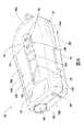
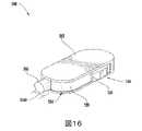
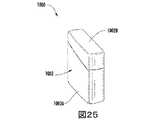
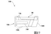
本開示の喫煙物品は、概して、筐体、ならびに筐体に連結され及び/または筐体内に位置付けられた複数の追加の構成要素を含み、構成要素のいくつかは筐体に対して可動である。筐体の全体的設計は様々であり得、筐体の全体的なサイズ及び形状は様々であり得る。喫煙物品は、外側本体またはシェル、例えば紙巻タバコまたは葉巻の形状の一部分に似た細長い本体によって画定され得るカートリッジを含んでもよい。例えば、カートリッジの外側シェルまたは本体は、実質的に管形状であるために従来の紙巻きタバコまたは葉巻の形状に似ている場合がある。いくつかの実施形態では、筐体は、1つ以上の再利用可能な構成要素(例えば、充電式電池、及びその物品の動作を制御するための様々な電子部品)を含み得、カートリッジは取り外し可能、補充可能、及び/または使い捨てであってもよい。 Smoking articles of the present disclosure generally include a housing and a plurality of additional components coupled to and/or positioned within the housing, some of the components being movable relative to the housing. . The overall design of the housing may vary, and the overall size and shape of the housing may vary. The smoking article may comprise a cartridge which may be defined by an outer body or shell, for example an elongated body resembling a portion of the shape of a cigarette or cigar. For example, the outer shell or body of the cartridge may be substantially tubular in shape to resemble the shape of a conventional cigarette or cigar. In some embodiments, the housing may contain one or more reusable components (e.g., rechargeable batteries and various electronic components for controlling the operation of the article), and the cartridge is removable. It may be disposable, refillable, and/or disposable.
本開示のエアロゾル送達デバイスは、電源(すなわち、電力源)、少なくとも1つの制御構成要素(例えば、電源からエアロゾル送達デバイスの他の構成要素への電流を制御することなどによる、熱生成のための作動、制御、調節、及び/または停止電力のための手段)、加熱器または熱生成構成要素(例えば、「噴霧器」の一部と一般に称される電気抵抗加熱要素または構成要素)、及びエアロゾル前駆体組成物(例えば、一般的には、「スモークジュース(smoke juice)」、「Eリキッド(e-liquid)」、及び「Eジュース(e-juice)」と一般に称される成分などの、十分な熱が加えられるとエアロゾルを生む能力のある液体)、及びエアロゾル吸入のためにエアロゾル送達デバイスを吸うことを可能にする吸い口領域または先端(例えば、吸う際に、生成されたエアロゾルがそこから引き出されるような、物品を通る画定された気流の通路)のある組み合わせを備えることが最も好ましい。加熱要素がエアロゾル前駆体組成物を加熱すると、消費者による吸入に好適な物理的形態でエアロゾルが形成、放出、または生成される。前述の用語は、放出する(release)、放出している(releasing)、放出する(releases)、または放出された(released)への言及が、形成する(form)または生成する(generate)、形成している(forming)または生成している(generating)、形成する(forms)または生成する(generates)、及び放出された(formed)または生成された(generated)を含むように、置き換え可能であることを意味することに留意すべきである。具体的には、吸入可能な物質は、蒸気もしくはエアロゾルまたはこれらの混合物の形態で放出される。 The aerosol delivery device of the present disclosure includes a power source (i.e., power source), at least one control component (e.g., for heat generation, such as by controlling current from the power source to other components of the aerosol delivery device). means for actuation, control, regulation, and/or stopping power), heaters or heat generating components (e.g., electrical resistance heating elements or components commonly referred to as part of a "nebulizer"), and aerosol precursors. enough body composition (e.g., ingredients commonly referred to as "smoke juice," "e-liquid," and "e-juice"); a liquid capable of forming an aerosol upon the application of sufficient heat), and a mouthpiece region or tip that allows the aerosol delivery device to be sucked for aerosol inhalation (e.g., from which the aerosol produced upon sucking It is most preferred to have some combination of defined airflow passageways through the article as they are withdrawn. When the heating element heats the aerosol precursor composition, an aerosol is formed, emitted or produced in a physical form suitable for inhalation by the consumer. The foregoing terms are used when reference to release, releasing, releases, or released forms or generates, forms interchangeable to include forming or generating, forms or generates, and formed or generated It should be noted that Specifically, inhalable substances are released in the form of vapors or aerosols or mixtures thereof.
上述のように、エアロゾル送達デバイスは、加熱器への電力供給、制御システムへの電力供給、インジケータへの電力供給、及び同様のものなど、エアロゾル送達デバイスに様々な機能性を提供するのに十分な電流を提供するための電池または他の電力源(例えば、蓄電器)を組み込み得る。電源は様々な実施形態を呈し得る。好ましくは、電源は、加熱要素を迅速に加熱してエアロゾル形成を提供し、所望の期間の使用を介してエアロゾル送達デバイスに電力供給するのに十分な電力を送達することができる。電源は、エアロゾル送達デバイスを容易に取り扱うことができるように、エアロゾル送達デバイス内に簡便に収まるようなサイズ決定されることが好ましい。加えて、好ましい電源は、望ましい喫煙体験を損なうことがないように、十分に軽量なものである。本デバイスで使用するための電池は、交換可能及び/または充電可能であり得、故に、典型的な交流電気コンセントへの接続、車の充電器(すなわち、シガーソケットレセプタクル)への接続、及びユニバーサルシリアルバス(USB)ケーブルまたは接続器などを介したコンピュータへの接続を含む、任意の種類の再充電技術と組み合わせてもよい。電力源の例は、Peckerarらの米国特許出願公開第2010/0028766号に記載されており、この開示はその全体が参照により本明細書に組み込まれる。 As described above, the aerosol delivery device is sufficient to provide various functionalities to the aerosol delivery device, such as powering heaters, powering control systems, powering indicators, and the like. A battery or other power source (eg, capacitor) may be incorporated to provide sufficient current. The power supply may take on various embodiments. Preferably, the power source is capable of delivering sufficient power to rapidly heat the heating element to provide aerosol formation and to power the aerosol delivery device over a desired period of use. The power source is preferably sized to conveniently fit within the aerosol delivery device so that the aerosol delivery device can be easily handled. Additionally, the preferred power source is sufficiently lightweight so as not to detract from the desired smoking experience. Batteries for use in the device may be replaceable and/or rechargeable, thus connecting to a typical AC electrical outlet, connecting to a car charger (i.e., cigarette lighter receptacle), and universal It may be combined with any kind of recharging technology, including connection to a computer via a serial bus (USB) cable or connector or the like. Examples of power sources are described in US Patent Application Publication No. 2010/0028766 to Peckerar et al., the disclosure of which is incorporated herein by reference in its entirety.
本開示に従うエアロゾル送達デバイスは、エアロゾル生成が所望されるとき(例えば、使用中に吸引する際)に、熱生成構成要素への電力供給の制御のためのセンサまたは検知器を好ましく組み込む。例えば、このように、使用中にエアロゾル生成部品が吸われないときに、熱生成構成要素への電力供給を停止し、吸う際に、熱生成構成要素による熱生成を作動するまたは誘発するために電力供給を開始するための様式または方法が提供される。例えば、フローセンサに対して、エアロゾル送達デバイスのための様々なマイクロコントローラ、センサ、及びスイッチを含む、代表的な電流調整構成要素及び他の電流制御構成要素は、Gerthらの米国特許第4,735,217号、Brooksらの同第4,947,874、McCaffertyらの同第5,372,148号、Fleischhauerらの同第6,040,560号、Nguyenらの同第7,040,314号、及びPanらの同第8,205,622、Fernandoらの米国特許出願公開第2009/0230117号、及びColletらの同第2014/0060554、ならびに2013年3月15日出願のAmpoliniらの米国特許出願第13/837,542号、2014年3月13日出願のHenryらの同第14/209,191号に記載され、これらの全てはその全体が参照により本明細書に組み込まれる。追加の代表的な種類の感知または検知機構、構造、構成要素、構成、及びこれらの一般的な動作方法は、Sprinkel,Jr.の米国特許第5,261,424号、McCaffertyらの同第5,372,148号、及びFlickのPCT国際公開第2010/003480に記載され、これらの全てはその全体が参照により本明細書に組み込まれる。 Aerosol delivery devices according to the present disclosure preferably incorporate sensors or detectors for control of power delivery to heat-producing components when aerosol production is desired (eg, when inhaled during use). For example, in this way, when the aerosol-generating component is not inhaled during use, power is removed from the heat-producing component, and upon inhalation, to activate or induce heat production by the heat-producing component. A modality or method is provided for initiating power delivery. For example, for flow sensors, representative current regulation and other current control components, including various microcontrollers, sensors, and switches for aerosol delivery devices, are described in Gerth et al., US Pat. 735,217, Brooks et al. 4,947,874, McCafferty et al. 5,372,148, Fleischhauer et al. 6,040,560, Nguyen et al. and U.S. Patent Application Publication Nos. 2009/0230117 to Fernando et al., and 2014/0060554 to Collet et al., and Ampolini et al. No. 13/837,542 to Henry et al., No. 14/209,191 filed March 13, 2014, all of which are incorporated herein by reference in their entireties. Additional representative types of sensing or detection mechanisms, structures, components, configurations, and their general methods of operation are described in Sprinkel, Jr.; US Pat. No. 5,261,424 to McCafferty et al., US Pat. incorporated.
いくつかの実施形態では、エアロゾル送達デバイスは、1つ以上の発光ダイオードを含み得るインジケータを含んでもよい。インジケータは、接続器回路を介して制御構成要素と通信し、例えば、フローセンサによって検知されるように、ユーザが吸い口を吸う間に、照明することができる。 In some embodiments, an aerosol delivery device may include an indicator, which may include one or more light emitting diodes. The indicator communicates with the control component via a connector circuit and can illuminate while the user puffs, as sensed by a flow sensor, for example.
筐体に含まれ得る様々な要素は、全体が参照により本明細書に組み込まれる、2014年2月28日出願のWormらの米国特許出願第14/193,961号に記載されている。またさらなる構成要素を本開示のエアロゾル送達デバイス内で利用することができる。例えば、Sprinkelらの米国特許第5,154,192号は喫煙物品のためのインジケータを開示し、Sprinkel,Jr.の米国特許第5,261,424号はデバイスの吸い口と関連付けられ、一吸いすることと関連付けられたユーザの唇の働きを検出し、次いで加熱を誘発し得る圧電センサを開示し、McCaffertyらの米国特許第5,372,148号は、吸い口を介した圧力降下に応答して加熱負荷アレイへのエネルギー流を制御するための吸入センサを開示し、Harrisらの米国特許第5,967,148号は、挿入された構成要素の赤外線透過率の非均一性を検出する識別装置、及び構成要素がレセプタクルに挿入されると検出ルーチンを実行する制御器を含む喫煙デバイス内のレセプタクルを開示し、Fleischhauerらの米国特許第6,040,560号は、複数の差動移相を持つ規定の実行可能な電力サイクルを記載し、Watkinsらの米国特許第5,934,289号は、フォトニックオプトロニック構成要素を開示し、Countsらの米国特許第5,954,979号は、喫煙デバイスを通る吸引抵抗を改変するための手段を開示し、Blakeらの米国特許第6,803,545号は、喫煙デバイス内で使用するための特定の電池構成を開示し、Griffenらの米国特許第7,293,565号は、喫煙デバイスと共に使用するための様々な充電システムを開示し、Fernandoらの米国特許第8,402,976号は、充電を促進し、デバイスのコンピュータ制御を可能にする喫煙デバイスのためのコンピュータインターフェーシング手段を開示し、Fernandoらの米国特許第8,689,804号は、喫煙デバイスのための識別システムを開示し、Flickの国際公開第2010/003480号は、エアロゾル生成システム内での吸入を示す流体流感知システムを開示し、以上の開示の全ては、その全体が参照により本明細書に組み込まれる。電子エアロゾル送達物品に関連する構成要素、及び本物品に使用され得る開示される材料または構成要素のさらなる例としては、Gerthらの米国特許第4,735,217号、Morganらの米国特許第5,249,586号、Higginsらの米国特許第5,666,977号、Adamsらの米国特許第6,053,176号、Whiteの米国第6,164,287号、Vogesの米国特許第6,196,218号、Felterらの米国特許第6,810,883号、Nicholsの米国特許第6,854,461号、Honの米国特許第7,832,410号、Kobayashiの米国特許第7,513,253号、Hamanoの米国特許第7,896,006号、Shayanの米国特許第6,772,756号、Honの米国特許第8,156,944号及び同第8,375,957号、Honの米国特許出願公開第2006/0196518号及び同第2009/0188490号、Thorensらの米国特許出願公開第2009/0272379号、Monseesらの米国特許出願公開第2009/0260641号及び同第2009/0260642号、Oglesbyらの米国特許出願公開第2008/0149118号及び同第2010/0024834号、Wangの米国特許出願公開第2010/0307518号、Honの国際公開第2010/091593号、Fooの国際公開第2013/089551号、ならびに2013年3月15日出願のDePianoらの米国特許出願第13/841,233号が挙げられ、これらの各々は、その全体が参照により本明細書に組み込まれる。 Various elements that can be included in the housing are described in US Patent Application No. 14/193,961 to Worm et al., filed February 28, 2014, which is incorporated herein by reference in its entirety. Further components can also be utilized within the aerosol delivery devices of the present disclosure. For example, Sprinkel et al., US Pat. No. 5,154,192, disclose indicators for smoking articles; U.S. Pat. No. 5,261,424 to McCafferty et al. discloses a piezoelectric sensor associated with the mouthpiece of the device that can detect the action of the user's lips associated with sucking and then induce heating, McCafferty et al. U.S. Pat. No. 5,372,148 to Harris et al. discloses an inhalation sensor for controlling energy flow to a heating load array in response to a pressure drop across the mouthpiece; , 148 discloses a receptacle in a smoking device that includes an identification device for detecting non-uniformity in infrared transmission of an inserted component, and a controller that executes a detection routine when the component is inserted into the receptacle. US Pat. No. 6,040,560 to Fleischhauer et al. describes a defined viable power cycle with multiple differential phase shifts, and US Pat. No. 5,934,289 to Watkins et al. US Pat. No. 5,954,979 to Counts et al. discloses a means for modifying the resistance to draw through a smoking device, US Pat. No. 6,803,545 to Blake et al. disclose certain battery configurations for use in smoking devices; Griffen et al., U.S. Pat. No. 7,293,565, disclose various charging systems for use with smoking devices; U.S. Pat. No. 8,402,976 to Fernando et al. discloses computer interfacing means for a smoking device that facilitates charging and allows computer control of the device; discloses an identification system for a smoking device, Flick WO 2010/003480 discloses a fluid flow sensing system indicating inhalation within an aerosol generating system, all of the above disclosures in their entirety. is incorporated herein by reference. Additional examples of components associated with electronic aerosol delivery articles, and of the disclosed materials or components that can be used in such articles, include US Pat. No. 4,735,217 to Gerth et al. Higgins et al., U.S. Patent No. 5,666,977; Adams et al., U.S. Patent No. 6,053,176; White, U.S. Patent No. 6,164,287; 196,218, Felter et al. U.S. Pat. No. 6,810,883, Nichols U.S. Pat. No. 6,854,461, Hon U.S. Pat. No. 7,832,410, Kobayashi U.S. Pat. , 253, Hamano U.S. Pat. No. 7,896,006, Shayan U.S. Pat. No. 6,772,756, Hon U.S. Pat. U.S. Patent Application Publication Nos. 2006/0196518 and 2009/0188490 to Thorens et al., U.S. Patent Application Publication Nos. 2009/0272379 to Thorens et al. , Oglesby et al., U.S. Patent Application Publication Nos. 2008/0149118 and 2010/0024834; Wang, U.S. Patent Application Publication No. 2010/0307518; Hon, WO2010/091593; 089551, and US Patent Application No. 13/841,233 to DePiano et al., filed March 15, 2013, each of which is incorporated herein by reference in its entirety.
蒸気前駆体組成物とも称されるエアロゾル前駆体組成物は、例として、多価アルコール(例えば、グリセリン、プロピレングリコール、またはこれらの混合物)のいずれか、ニコチン、タバコ、タバコ抽出物、及び/または風味剤を含む、種々の成分を含んでもよい。エアロゾル前駆体組成物に含まれ得る様々な成分は、全体が参照により本明細書に組み込まれる、Robinsonらの米国特許第7,726,320号に記載されている。さらなる代表的な種類のエアロゾル前駆体組成物は、Sensabaugh,Jr.らの米国特許第4,793,365号、Jakobらの米国特許第5,101,839号、BiggsらのPCT国際公開第98/57556号、及びChemical and Biological Studies on New Cigarette Prototypes that Heat Instead of Burn Tobacco,R.J.Reynolds Tobacco Company Monograph(1988)に示され、これらの開示は参照により本明細書に組み込まれる。本開示のエアロゾル送達デバイスに用いられ得る他のエアロゾル前駆体としては、R. J. Reynolds Vapor CompanyのVUSE(登録商標)製品、Lorillard TechnologiesのBLU(商標)製品、Mistic EcigsのMistic Menthol製品、及びCN Creative Ltd.のVype製品に含まれるエアロゾル前駆体が挙げられる。Johnson Creek Enterprises LLCから入手可能な、電子タバコのためのいわゆる「スモークジュース(Smoke Juices)」もまた望ましい。本開示に従って使用し得るエアロゾル前駆体材料のための追加の例示的な配合は、Zhengらの米国特許公開第2013/0008457号及びChongらの米国特許公開第2013/0213417号に記載され、これらの開示は全体が参照により本明細書に組み込まれる。 Aerosol precursor compositions, also referred to as vapor precursor compositions, include, by way of example, any polyhydric alcohol (e.g., glycerin, propylene glycol, or mixtures thereof), nicotine, tobacco, tobacco extract, and/or Various ingredients may be included, including flavoring agents. Various components that can be included in the aerosol precursor composition are described in US Pat. No. 7,726,320 to Robinson et al., which is incorporated herein by reference in its entirety. A further representative type of aerosol precursor composition is described by Sensabaugh, Jr. U.S. Pat. No. 4,793,365 to Jakob et al., U.S. Pat. No. 5,101,839 to Jakob et al., PCT International Publication No. 98/57556 to Biggs et al., and Chemical and Biological Studies on New Cigarette Prototypes that Heat Install of Burn Tobacco, R.; J. Reynolds Tobacco Company Monograph (1988), the disclosures of which are incorporated herein by reference. Other aerosol precursors that can be used in the aerosol delivery device of the present disclosure include R.I. J. VUSE® products from Reynolds Vapor Company, BLU™ products from Lorillard Technologies, Mystic Menthol products from Mystic Ecigs, and CN Creative Ltd. Aerosol Precursors included in the Vype products of . Also desirable are so-called "Smoke Juices" for electronic cigarettes available from Johnson Creek Enterprises LLC. Additional exemplary formulations for aerosol precursor materials that may be used in accordance with the present disclosure are described in US Patent Publication No. 2013/0008457 to Zheng et al. and US Patent Publication No. 2013/0213417 to Chong et al. The disclosure is incorporated herein by reference in its entirety.
エアロゾル送達デバイスは、好ましくは貯蔵器を含む。いくつかの実施形態では、貯蔵器は、液体エアロゾル前駆体を収容するための容器、繊維基材、または繊維基材と容器との組み合わせを備えてもよい。貯蔵器としての使用に好適な繊維基材は、不織繊維の複数の層を備えてもよく、実質的に管の形状に形成されてもよい。例えば、形成された管は、エアロゾル送達デバイスでの使用のためのカートリッジの外側本体またはシェル内の位置付けのために成形及びサイズ決定されてもよい。例えば、液体構成要素は、繊維基材によって吸着的に保持されてもよく、かつ/または貯蔵容器内に保持されてもよい。貯蔵器は、好ましくは液体輸送要素と流体連通している。故に、液体輸送要素は、毛管作用、及び/または例えばポンプもしくは弁を用いた制御された移動などの能動輸送などを介して、貯蔵器から加熱要素へ液体を輸送するように構成され得る。基材、貯蔵器、またはエアロゾル前駆体を支持する他の構成要素の代表的な種類は、Newtonの米国特許第8,528,569号、ならびに2013年3月15日出願のChapmanらの米国特許出願第13/802,950、2013年8月28日出願のDavisらの同第14/011,192号、及び2014年2月3日出願のBlessらの同第14/170,838号に記載され、これらの開示は全体が参照により本明細書に組み込まれる。 Aerosol delivery devices preferably include a reservoir. In some embodiments, the reservoir may comprise a container, a fibrous substrate, or a combination of a fibrous substrate and a container for containing the liquid aerosol precursor. A fibrous substrate suitable for use as a reservoir may comprise multiple layers of nonwoven fibers and may be formed into a substantially tubular shape. For example, a formed tube may be shaped and sized for positioning within the outer body or shell of a cartridge for use in an aerosol delivery device. For example, the liquid component may be adsorbably retained by the fibrous substrate and/or retained within a reservoir. The reservoir is preferably in fluid communication with the liquid transport element. Thus, the liquid transport element may be configured to transport liquid from the reservoir to the heating element, such as via capillary action and/or active transport, such as controlled movement using a pump or valve. Representative types of substrates, reservoirs, or other components that support aerosol precursors are described in US Pat. No. 8,528,569 to Newton and US Pat. No. 13/802,950, Davis et al. No. 14/011,192 filed Aug. 28, 2013, and Bless et al. No. 14/170,838 filed Feb. 3, 2014. and the disclosures of which are incorporated herein by reference in their entirety.
液体輸送要素は、加熱要素と直接接触してもよい。様々なウィッキング材料、ならびに特定の種類のエアロゾル送達デバイスにおけるそれらのウィッキング材料の構成及び動作は、全体が参照により本明細書に組み込まれる、2013年1月30日出願のSearsらの米国特許出願第13/754,324に示されている。上述の文書により開示された種々の材料は、様々な実施形態での本デバイスに組み込まれ得、上述の開示の全てはそれらの全体が参照により本明細書に組み込まれる。 The liquid transport element may be in direct contact with the heating element. Various wicking materials, and the construction and operation of those wicking materials in certain types of aerosol delivery devices, are incorporated herein by reference in their entirety. No. 13/754,324. Various materials disclosed by the above documents can be incorporated into the present device in various embodiments, all of the above disclosures being incorporated herein by reference in their entireties.
加熱要素は、液体輸送要素の周りに巻き付けられた複数のコイルを画定するワイヤを備えてもよい。いくつかの実施形態では、加熱要素は、全体が参照により本明細書に組み込まれる、Wardらの米国特許出願公開第2014/0157583号に記載されているように、液体輸送要素の周りにワイヤを巻き付けることによって形成され得る。さらに、いくつかの実施形態では、ワイヤは、全体が参照により本明細書に組み込まれる、2013年3月14日出願のDePianoらの米国特許出願第13/827,994号に記載されているように、可変のコイル間隔を画定し得る。電流がそれを通して印加されるときに熱を生み出すように構成された材料の様々な実施形態を用いて、加熱要素を形成することができる。ワイヤコイルを形成し得る例示的な材料としては、Kanthal(FeCrAl)、Nichrome、二珪化モリブデン(MoSi2)、珪化モリブデン(MoSi)、アルミニウムでドープした二珪化モリブデン(Mo(Si,Al)2)、黒煙及び黒煙系材料、ならびにセラミック(例えば、正または負の温度係数を有するセラミック)が挙げられる。いくつかの実施形態では、全体が参照により本明細書に組み込まれる、2013年3月15日出願のDePianoらの米国特許出願第13/842,125号に記載されているように、型打ちした加熱要素を噴霧器内で用いてもよい。上記に加えて、さらなる代表的な加熱要素、及びそれらの内部で使用するための材料は、Countsらの米国特許第5,060,671号、Deeviらの米国特許第5,093,894号、Deeviらの米国特許第5,224,498号、Sprinkel Jr.らの米国特許第5,228,460号、Deeviらの米国特許第5,322,075号、Deeviらの米国特許第5,353,813号、Deeviらの米国特許第5,468,936号、Dasの米国特許第5,498,850号、Dasの米国特許第5,659,656号、Deeviらの米国特許第5,498,855号、Hajaligolの米国特許第5,530,225号、Hajaligolの米国特許第5,665,262号、Dasらの米国特許第5,573,692号、及びFleischhauerらの米国特許第5,591,368号に記載され、これらの開示は、その全体が参照により本明細書に組み込まれる。さらに、他の実施形態では、化学的加熱を用いてもよい。加熱器及び加熱器の形成に用いられる材料の様々な追加の例は、上述のように、全体が参照により本明細書に組み込まれる、Collettらの米国特許出願公開第2014/0060554に記載されている。The heating element may comprise a wire defining a plurality of coils wrapped around the liquid transport element. In some embodiments, the heating element comprises a wire around the liquid transport element, as described in US Patent Application Publication No. 2014/0157583 to Ward et al., which is incorporated herein by reference in its entirety. It can be formed by winding. Further, in some embodiments, the wire is a Additionally, variable coil spacing can be defined. Various embodiments of materials configured to generate heat when an electrical current is applied through them can be used to form the heating element. Exemplary materials from which the wire coil may be formed include Kanthal (FeCrAl), Nichrome, molybdenum disilicide (MoSi2 ), molybdenum silicide (MoSi), aluminum-doped molybdenum disilicide (Mo(Si,Al)2 ). , black smoke and black smoke-based materials, and ceramics (eg, ceramics with positive or negative temperature coefficients). In some embodiments, stamped as described in US Patent Application Serial No. 13/842,125 to DePiano et al., filed March 15, 2013, which is incorporated herein by reference in its entirety. A heating element may be used within the nebulizer. In addition to the above, additional exemplary heating elements and materials for use therein are described in Counts et al., US Pat. No. 5,060,671; U.S. Pat. No. 5,224,498 to Deevi et al., Sprinkel Jr.; US Patent No. 5,228,460 to Deevi et al., US Patent No. 5,322,075 to Deevi et al., US Patent No. 5,353,813 to Deevi et al., US Patent No. 5,468,936 to Deevi et al. , Das U.S. Patent No. 5,498,850; Das U.S. Patent No. 5,659,656; Deevi et al. U.S. Patent No. 5,498,855; Hajaligol, U.S. Pat. No. 5,665,262, Das et al., U.S. Pat. No. 5,573,692, and Fleischhauer et al., U.S. Pat. incorporated herein by reference. Additionally, in other embodiments, chemical heating may be used. Various additional examples of heaters and materials used to form the heaters are described in US Patent Application Publication No. 2014/0060554 to Collett et al., which is incorporated herein by reference in its entirety, as noted above. there is
種々の加熱構成要素が、本エアロゾル送達デバイスに使用され得る。様々な実施形態では、1つ以上のマイクロヒータまたは同様の固体状の加熱器が使用され得る。本開示のデバイスの使用に好適なマイクロヒータ及びマイクロヒータを組み込む噴霧器の実施形態は、全体が参照により本明細書に組み込まれる、Collettらの米国特許出願公開第2014/0060554号に記載されている。 Various heating components can be used in the present aerosol delivery device. In various embodiments, one or more microheaters or similar solid state heaters may be used. Embodiments of microheaters and nebulizers incorporating microheaters suitable for use with the devices of the present disclosure are described in US Patent Application Publication No. 2014/0060554 to Collett et al., which is incorporated herein by reference in its entirety. .
1つ以上の加熱端子(例えば、正及び負の端子)は、電源との電気接続を形成するように加熱要素と接続し得、かつ/または端子は、エアロゾル送達デバイスの1つ以上の制御要素と接続し得る。さらに、電子制御構成要素及びそれによって行われる機能の様々な例は、全体が参照により本明細書に組み込まれる、Searsらの米国特許出願公開第2014/0096781号に記載されている。 One or more heating terminals (e.g., positive and negative terminals) may connect with the heating element to form an electrical connection with a power source, and/or the terminals may be connected to one or more control elements of the aerosol delivery device. can connect with Additionally, various examples of electronic control components and functions performed thereby are described in US Patent Application Publication No. 2014/0096781 to Sears et al., which is incorporated herein by reference in its entirety.
本開示に従うエアロゾル送達デバイスの様々な構成要素は、当該技術分野で説明され、市販されている構成要素から選択することができる。例えば、全体が参照により本明細書に組み込まれる、Sebastianらの米国特許出願公開第2014/0000638号に開示されている、電子喫煙物品内の複数のエアロゾル化可能な材料の制御可能な送達のための貯蔵器及び加熱器システムを参照する。 Various components of aerosol delivery devices according to the present disclosure can be selected from components described in the art and commercially available. For the controllable delivery of multiple aerosolizable materials within an electronic smoking article, for example, as disclosed in US Patent Application Publication No. 2014/0000638 to Sebastian et al., which is incorporated herein by reference in its entirety. See the reservoir and heater system of
さらなる実施形態では、エアロゾル送達デバイスの1つ以上の構成要素は、1つ以上の炭素材料から形成されてもよく、このことは、生分解性及びワイヤの欠如という観点で利点を提供し得る。これに関連して、加熱要素は泡状炭素を含んでもよく、貯蔵器は炭素化布帛を含んでもよく、また黒鉛を用いて電池及び制御器と電気接続を形成してもよい。炭素系カートリッジの例示的な実施形態は、全体が参照により本明細書に組み込まれる、Griffithらの米国特許出願公開第2013/0255702号において提供されている。 In further embodiments, one or more components of the aerosol delivery device may be formed from one or more carbon materials, which may offer advantages in terms of biodegradability and lack of wires. In this regard, the heating element may comprise foam carbon, the reservoir may comprise carbonized fabric, and graphite may be used to form electrical connections with the battery and controller. Exemplary embodiments of carbon-based cartridges are provided in US Patent Application Publication No. 2013/0255702 to Griffith et al., which is incorporated herein by reference in its entirety.
エアロゾル送達デバイスは、多くの場合、紙巻きタバコまたは葉巻などの特定の伝統的な喫煙デバイスの態様を模擬した様式で構成される。これに関連して、エアロゾル送達デバイスは、典型的に、実質的に円筒形の構成を画定する。例えば、エアロゾル送達デバイスは、多くの場合、実質的に円筒形の構成を画定するために端部同士の関係で取り付けられる制御体及びカートリッジを含む。かかる構成は伝統的な喫煙物品と類似した外見及び感覚を提供し得る一方で、これらの構成は特定の損傷を被り得る。例えば、円筒形の構成のエアロゾル送達デバイスは、使用しない際に、エアロゾル送達デバイスを所望の位置で保持するのに使用可能な付着点を画定しない場合がある。さらに、円筒形の構成は、吸い口が周囲の環境に露出し、それにより汚染の影響を受けやすくなることをもたらし得る。したがって、伝統的な喫煙物品に関連する形状とは異なる構成を有するエアロゾル送達デバイスを提供することが望ましい。 Aerosol delivery devices are often configured in a manner that mimics aspects of certain traditional smoking devices, such as cigarettes or cigars. In this regard, aerosol delivery devices typically define a substantially cylindrical configuration. For example, aerosol delivery devices often include a control body and a cartridge mounted in end-to-end relationship to define a substantially cylindrical configuration. While such constructions may provide a similar look and feel to traditional smoking articles, these constructions may suffer certain injuries. For example, an aerosol delivery device with a cylindrical configuration may not define attachment points that can be used to hold the aerosol delivery device in a desired position when not in use. Additionally, the cylindrical configuration can result in the mouthpiece being exposed to the surrounding environment, making it susceptible to contamination. Accordingly, it is desirable to provide an aerosol delivery device having a configuration that differs from the shapes associated with traditional smoking articles.
これに関連して、図1は、本開示の例示的な実施形態に従う、エアロゾル送達デバイス100を通した改訂された断面図を概略的に示す。以下に説明されるように、エアロゾル送達デバイス100は、エアロゾル送達デバイスの様々な実施形態に対して上述されている構成要素の一部または全てを含み得る。 In this regard, FIG. 1 schematically shows a revised cross-sectional view through an
示されるように、一実施形態では、エアロゾル送達デバイス100は、筐体102とカートリッジ200とを含み得る。いくつかの実施形態では、カートリッジ200は、筐体102の少なくとも一部分、またはその全体に対して可動であり得る。具体的には、カートリッジ200は、筐体102の少なくとも一部分に対して、図1に示される後退した構成と図2に示される延出した構成との間で可動である。筐体102に関するカートリッジ200の移動に関連する機構及び様式についての詳細が以下に説明される。 As shown, in one embodiment,
いくつかの実施形態では、筐体102及びカートリッジ200の一方または両方は、使い捨てまたは再利用可能と称され得る。エアロゾル送達デバイス100は、筐体102またはカートリッジ200内に配置された、または他の様式でそれらに連結された様々な他の構成要素を含み得る。これらの構成要素は、様々な様式のいずれかにおいて、筐体102とカートリッジ200との間に配置され得る。したがって、記載される実施形態は、例示的な目的でのみ提供されることは理解されたい。 In some embodiments, one or both of
カートリッジ200の1つの例示的な実施形態は、図3に示される。示されるように、カートリッジ200は、本開示の例示的な実施形態に従う、基部シッピングプラグ202、基部204、制御構成要素端子206、電子制御構成要素208、流管210、噴霧器212、貯蔵器基材214、外側本体216、ラベル218、吸い口220、及び吸い口シッピングプラグ222を備え得る。基部204は、外側本体216の第1の端部に連結し、吸い口220は、外側本体の反対側の第2の端部に連結して、ラベル218、吸い口シッピングプラグ222、及び基部シッピングプラグ202を除く、カートリッジ200の残りの構成要素をその内部に少なくとも部分的に封入し得る。基部204は、電源を含む関連デバイスに係合するように構成され得る。いくつかの実施形態では、基部204は、全体が参照により本明細書に組み込まれる、2013年3月15日出願のNovakらの米国特許出願第13/840,264号に開示されるような、カートリッジと電源を含む関連デバイスとの間の相対的回転を実質的に防ぐ回転防止特徴を備えてもよい。 One exemplary embodiment of
基部シッピングプラグ202は、カートリッジ200の使用前に基部204に係合しそれを保護するように構成され得る。同様に、吸い口シッピングプラグ222は、カートリッジ200の使用前に吸い口220に係合しそれを保護するように構成され得る。制御構成要素端子206、電子制御構成要素208、流管210、噴霧器212、及び貯蔵器基材214は、外側本体216内に保持され得る。ラベル218は、外側本体216を少なくとも部分的に取り囲み、製品識別物などの情報をその上に含んでもよい。
噴霧器212は、第1の加熱端子234a及び第2の加熱端子234b、液体輸送要素238、ならびに加熱要素240を備え得る。これに関連して、貯蔵器基材214は、エアロゾル前駆体組成物を保持するように構成され得る。貯蔵器基材214は、貯蔵器基材214から加熱要素240へ液体を輸送するように(例えば、毛管作用を介して、液体輸送要素238と流体連通している。
カートリッジ200内に含まれ得る構成要素に関する様々な他の詳細は、例えば、全体が参照により本明細書に組み込まれる、2013年3月15日出願のNovakらの米国特許出願第13/840,264号において提供されている。これに関連して、その図7は、基部及び制御構成要素端子の拡大分解図を示し、その図8は、組立構成にある基部及び制御構成要素端子の拡大斜視図を示し、その図9は、組立構成にある、基部、制御構成要素端子、電子制御構成要素、及び噴霧器の加熱端子の拡大斜視図を示し、その図10は、組立構成にある、基部、噴霧器、及び制御構成要素の拡大斜視図を示し、その図11は、その図10の組立体の反対側の斜視図を示し、その図12は、組立構成にある、基部、噴霧器、流管、及び貯蔵器基材の拡大斜視図を示し、その図13は、組立構成にある基部及び外側本体の斜視図を示し、その図14は、組立構成にあるカートリッジの斜視図を示し、その図15は、その図14のカートリッジ及び制御体のための連結器の第1の部分斜視図を示し、その図16は、その図14のカートリッジ及びその図11の連結器の反対側の第2の部分斜視図を示し、その図17は、回転防止機構を持つ基部を含むカートリッジの斜視図を示し、その図18は、回転防止機構を持つ連結器を含む制御体の斜視図を示し、その図19は、図18の制御体を持つ図17のカートリッジの整列を示し、その図20は、その図17のカートリッジ及びその図18の制御体を備えるエアロゾル送達デバイスを示し、これには、カートリッジの回転防止機構の接続器本体の回転防止機構との係合を示す、エアロゾル送達デバイスを通した改訂図が伴い、その図21は、回転防止機構を持つ基部の斜視図を示し、その図22は、回転防止機構を持つ連結器の斜視図を示し、その図23は、係合した構成にあるその図21の基部及びその図22の連結器を通した断面図を示す。 Various other details regarding components that may be included within
別の実施形態では、カートリッジ200は、全体が参照により本明細書に組み込まれる、2014年5月23日出願のBrinkleyらの米国特許出願第14/286,552号に開示されるカートリッジと実質的に類似する、または同一であってもよい。故に、例えば、カートリッジは、非管状の構成を画定するフローディレクタ、貯蔵器区画に対して密封された電子部品区画、及び/または本明細書に開示される様々な他の特徴及び構成要素のいずれかを含み得る。したがって、本明細書に記載されるカートリッジ200の特定の実施形態は、例示的な目的でのみ提供されることは理解されたい。これに関連して、カートリッジ200は、それに含まれ得る様々な代替的及び追加的な構成要素を踏まえ、外側本体216、吸い口220、噴霧器212、貯蔵器214、及び基部204のみを含むものとして図1に概略的に示される。 In another embodiment,
同様に、一実施形態では、筐体102は、その内部に位置付けられた、または他の様式でそこに連結された上述のカートリッジ200に係合するように構成された制御体の既存の実施形態の構成要素の一部または全てを含み得る。例えば、筐体402は、それぞれの全体が参照により本明細書に組み込まれる、2013年3月15日出願のNovakらの米国特許出願第13/840,264号、2014年5月23日出願のBrinkleyらの同第14/286,552号、及び2014年2月28日出願のWormらの同第14/193,961に開示される制御体に構成要素の一部または全てを含み得る。しかしながら、理解されるように、カートリッジ200は、他の実施形態ではこれらの構成要素の一部または全てを含み得る。 Similarly, in one embodiment,
例として、示される実施形態では(例えば、図1参照)、エアロゾル送達デバイス100は、筐体102内に位置付けられた電源104(例えば、電池)を含む。さらに、接続器106は、筐体102に可動に取り付けられ得る。カートリッジ200は、筐体102の少なくとも一部分に対して可動であるように、接続器106に係合され得る。いくつかの実施形態では、カートリッジ200は、接続器106に取り外し可能に係合され得、かつ交換可能であり得る。エアロゾル送達デバイス100は、そこに受容される制御器108を追加で含み得る。制御器108は、電力を電源104からカートリッジ200へと向け、噴霧器212を用いて貯蔵器214に保持されたエアロゾル前駆体組成物を加熱して蒸気を生み出すように構成され得、これはユーザが吸い口220を吸う間に発生し得る。 By way of example, in the embodiment shown (see, eg, FIG. 1),
カートリッジ200の1つ以上の構成要素は、接続器106との電気接続を形成するように構成され得る。例えば、図3のカートリッジ実施形態に関して、加熱要素240の両端にある第1の加熱端子234a及び第2の加熱端子234b(例えば、正及び負の端子)は、接続器106との電気接続を形成するように構成されている。さらに、電子制御構成要素208(図3参照)は、制御構成要素端子206(図3参照)を通した接続器106との電気接続を形成し得る。筐体102内の構成要素(例えば、制御器108)は、故に、電子制御構成要素208を用いて、カートリッジ200が本物であるか、及び/または他の機能を行うかを決定し得る。しかしながら、他の実施形態では、接続器106とカートリッジ200との間の接続は、電気的でない場合もある。換言すれば、接続器106とカートリッジ300との間の接続は、単純に機械的である場合もある。これらの実施形態では、噴霧はカートリッジ外で発生し得る、または噴霧はカートリッジと筐体との間の電気接続を必要としない、圧電または無線周波数噴霧などの他の方法を介して発生し得る。あるいは、電源はカートリッジ内に位置付けられてもよく、それにより接続器との電気接続は必要とされない。 One or more components of
使用中、ユーザは、エアロゾル送達デバイス100のカートリッジ200の吸い口220を吸い得る。これは、接続器106内またはカートリッジ200内の開口部を通して空気を吸い入れ得る。しかしながら、空気の流れは、他の実施形態では、エアロゾル送達デバイス100の他の部分を通して受容されてもよい。上述のように、いくつかの実施形態では、カートリッジ200は流管210(図3参照)を含んでもよい。流管210は、空気の流れを噴霧器212の加熱要素240(図3参照)に向けるように構成され得る。 During use, a user may suck on
以下に説明されるように、エアロゾル送達デバイス100内のセンサは、吸引を感知し得る。吸引が感知されると、制御器108は、第1の加熱端子234a及び第2の加熱端子234b(図3参照)を含む回路を通して電流を加熱要素240に向け得る。したがって、加熱要素240は、液体輸送要素238(図3参照)によって貯蔵器基材214からエアロゾル化ゾーンへ向けられたエアロゾル前駆体組成物を蒸発させ得る。故に、吸い口220は、それを吸う消費者への、それを通したエアロゾル(すなわち、吸引可能な形態の、エアロゾル前駆体組成物の成分)の通過を可能にする。 As described below, sensors within the
上述のように、カートリッジ200は、筐体102に対して可動であり得る。これに関連して、エアロゾル送達デバイス100は、作動装置110をさらに備え得る。具体的には、作動装置110は接続器106と連結され得る。それにより、作動装置110は、カートリッジ200に動作的に係合し得、かつ延出した構成と後退した構成との間でカートリッジを移動させるように構成され得る。 As noted above,
図2に示されるように、カートリッジ200が延出した構成にあるとき、吸い口220は露出し得る。換言すれば、カートリッジ200が延出した構成にあるとき、ユーザは吸い口をその唇に係合することができるように、吸い口220は筐体102外に位置付けられ得る。故に、カートリッジ200の延出した構成は、エアロゾル送達デバイス100が吸い口220上に吸引を受容するように構成された構成であり、それによりエアロゾル送達デバイスは、上述の様式でエアロゾルを生み出しユーザに送達し得る。 As shown in FIG. 2,
逆に、図1に示されるように、後退した構成において、吸い口220は延出した構成(図2参照)よりも筐体102と相対的に近い。後退した構成において、吸い口220は筐体102に対して平らであり得る。換言すれば、吸い口220の外表面は、筐体102の外表面と実質的に整列し得る。別の実施形態では、吸い口220は筐体102に対して窪みを有し得る。換言すれば、吸い口220の外表面と筐体102の外表面との間に間隙が提供され得る。 Conversely, in the retracted configuration, as shown in FIG. 1,
したがって、一実施形態では、カートリッジ200の吸い口220は、後退した構成において筐体102内に少なくとも部分的に受容され得る。別の実施形態では、後退した構成において、吸い口220を含むカートリッジ200の全体が、筐体102内に受容され得る。したがって、吸い口220を筐体102と相対的に近く位置付けることにより(例えば、部分的または全体をその内部に受容される)、吸い口は損傷から保護され得る。さらに、吸い口220は、後退した構成にあるとき、さもなければユーザの唇に移る、または加熱要素に接触しその性能に悪影響を及ぼし得る、汚染(例えば、リント、塵、または泥から)がより生じにくくなる。加えて、後退した構成において、カートリッジ200の吸い口220からの液体漏出(例えば、水滴)が、筐体102によって捕捉され得る。例えば、吸い口220からの液体漏出は、筐体102の周囲の部分に排水され、液体は保持され蒸発し得る。対照的に、伝統的な喫煙物品に似た構成を画定するエアロゾル送達デバイスは、典型的に、固定して位置付けされた吸い口を含み、吸い口はその周囲に露出し得、それにより、ユーザによって適切に保管されない場合に損傷または汚染の影響を受けやすく、特定の場合においてその周囲に液体(例えば、水滴)を漏出し得る。 Thus, in one embodiment,
上述のように、本開示の実施形態は、筐体の少なくとも一部分に対して、後退した構成と延出した構成との間で可動であるカートリッジを含むエアロゾル送達デバイスに関する。さらに上述のように、かかるエアロゾル送達デバイスは、本明細書の他の箇所に説明されているような幅広い種類の構成要素のいずれを含んでもよい。しかしながら、構成要素の例示的な構成を含むエアロゾル送達デバイスの実施形態が、以下に説明される。しかしながら、重ねて、示される構成要素は例示的な目的でのみ提供されることは理解されたい。したがって、カートリッジと筐体との間に同一または異なる様式で配置され得る、より多いもしくはより少ない数の構成要素、及び/または同一もしくは異なる構成要素は、本開示のエアロゾル送達デバイスの実施形態に含まれ得る。さらなる例として、一実施形態では、貯蔵器及び/または加熱器は、カートリッジ内ではなく筐体内に位置付けられてもよい。この実施形態では、カートリッジは、形成されたエアロゾルを生み出すのではなく、筐体で形成されたエアロゾルをユーザに送達し得る。したがって、いくつかの実施形態では、カートリッジは、ユーザが吸うストロー、管または同様のものを実質的に画定し得る。 As noted above, embodiments of the present disclosure relate to aerosol delivery devices that include cartridges movable between retracted and extended configurations with respect to at least a portion of the housing. Further, as noted above, such aerosol delivery devices may include any of a wide variety of components as described elsewhere herein. However, embodiments of aerosol delivery devices including exemplary configurations of components are described below. Again, however, it should be understood that the components shown are provided for illustrative purposes only. Thus, a greater or lesser number of components and/or the same or different components that may be arranged in the same or different manner between the cartridge and the housing are included in embodiments of the aerosol delivery device of the present disclosure. can be As a further example, in one embodiment the reservoir and/or heater may be located within the housing rather than within the cartridge. In this embodiment, the cartridge may deliver an aerosol formed in the housing to the user rather than generate a formed aerosol. Thus, in some embodiments, the cartridge may substantially define a straw, tube, or the like that is sucked by the user.
しかしながら、例として、図4~13は、本開示の例示的な実施形態に従う、追加の構成要素を含む、図4及び5のエアロゾル送達デバイス100の図を示す。具体的には、図4は、閉じた構成にあるエアロゾル送達デバイス100の斜視図を示し、図5は、延出した構成にあるエアロゾル送達デバイスの斜視図を示す。示されるように、筐体102は、ユーザの手の中に快適に収まるように構成された人間工学的な形状を画定し得る。これに関連して、筐体102は、互いに向き合って配置された底部102A及び上部102B、互いに向き合って配置された第1及び第2の側部102C、102D、ならびに互いに向き合って配置された前面102E及び背面102Fを画定し得る。ユーザの手の平におけるエアロゾル送達デバイス100のグリップを容易にするために、底部102Aは湾曲してもよく、側部102C、102Dは上部102Bに向かって勾配がつけられてもよい。しかしながら、筐体102の形状は限定されず、本明細書に記載される様々な要素に適応する、いかなる形状であってもよい。 By way of example, however, FIGS. 4-13 show views of the
加えて、いくつかの実施形態では、筐体102は、前面カバー102G及び背面カバー102Hを含み得る。前面カバー102Gは、筐体102の前面102Eを画定し得る。逆に、背面カバー102Hは、筐体102の背面102Fを画定し得る。 Additionally, in some embodiments, the
さらに、筐体102は、側部102C、102D間に延在する約20mm~約60mmの幅、前面102Eと背面102Fとの間に延在する約10mm~約50mmの厚さ、及び底部102Aと上部102Bとの間に延在する約40mm~約120mmの長さを画定し得る。いくつかの実施形態では、筐体は、明確に非円筒形であり得る。対照的に、伝統的な喫煙物品(例えば紙巻きタバコ)に似るように構成された典型的なエアロゾル送達デバイスは、実質的に円筒形の形状であり、約8mm~約15mmの直径、及び約80mm~約120mmの長手方向の長さを画定し得る。したがって、本開示のエアロゾル送達デバイスの幅は、快適性のレベル及び本開示のエアロゾル送達デバイスを掴むことに関連するグリップの安定性を改良するために、伝統的なエアロゾル送達デバイスの直径よりも実質的に大きい場合がある。逆に、本開示の(後退した構成にある)エアロゾル送達デバイスの長さは、本開示のエアロゾル送達デバイスの携帯性を改良するために、伝統的なエアロゾル送達デバイスの長さよりも小さい場合がある。 Further,
図5でさらに示されるように、エアロゾル送達デバイス100は、取り付け機構112を追加で含み得る。取り付け機構112は、別のデバイスに取り付けるように構成された、ループ、クリップ、リング、もしくはキーホルダー、カラビナ、または吊り紐などの他の機構を備え得る。したがって、エアロゾル送達デバイス100は、所望の位置に保持され得る。故に、例えば、ユーザはエアロゾル送達デバイス100を、エアロゾル送達デバイスの損傷または置き忘れが生じにくい、所望の位置により容易に安定させることができる。取り付け機構112は、使用中、カートリッジを吸うユーザへの干渉を回避するため、カートリッジ200がそこから延出する筐体102の端部(例えば、上部102B)から実質的に反対側に位置付けられ得る。 As further shown in FIG. 5,
エアロゾル送達デバイス100は、入力機構114を追加で含み得る。入力機構114は、ユーザからの入力を受容するように構成されたボタンまたはスイッチを備え得る。入力機構114が作動されると、エアロゾル送達デバイス100は、エアロゾル送達デバイスの状態に対応する出力を生み出し得る。例えば、エアロゾル送達デバイスは、音、振動、または光を出力し得る。図4に示されるように、エアロゾル送達デバイス100は、インジケータ116をさらに備え得る。インジケータ116は、光送信器116A(例えば、プラスチックまたはガラスであり、これらは所望の色に色付けされてもよい)を備え得る。さらに、インジケータ116は、白熱電球または発光ダイオード(LED)を備え得る、発光器116B(例えば、図6参照)を含み得る。それにより、発光器116Bは、光送信器116Aを照明し得、光送信器116Aは、それを通して外向きに光を向け、エアロゾル送達デバイス100の状態を出力し得る。
これに関連して、インジケータ116は、電源104または貯蔵器214(例えば、図1参照)の容量の残っているまたは使用済みの部分を示すために、点滅または他の様式で照明し得る。例えば、入力機構114の作動に際し、比較的多い数のインジケータ116の点滅は、電源104または貯蔵器214(例えば、図1参照)の比較的多い残容量に対応し得る。逆に、入力機構114の作動に際し、比較的少ない数のインジケータ116の点滅は、電源104または貯蔵器214(例えば、図1参照)の比較的少ない残容量に対応し得る。しかしながら、インジケータ116及び/または他の出力機構は、様々な他の情報を出力する、かつ/または様々な他の様式で情報を出力するためにも用いられ得る。出力され得る他の情報の例としては、エラーメッセージ、動作モード、使用履歴情報などが挙げられる。 In this regard,
さらに、いくつかの実施形態では、図5に示されるように、エアロゾル送達デバイス100は、ディスプレー118を含み得る。ディスプレー118は、インジケータ116に加えて、またはその代替として提供され得る。これに関連して、ディスプレー118は、エアロゾル送達デバイス100の状態に関する情報、エアロゾル送達デバイスの状態に無関係な情報(例えば、現在時刻)、及び/または情報を有さないグラフィックアート(例えば、ユーザの娯楽目的に提供されたグラフィックアート)を含む、様々な情報を出力するように構成され得る。それにより、ディスプレー118は、上述の情報(例えば、電源104または貯蔵器214の容量の残っているまたは使用済みの部分)のいずれかまたは全てを、図表形態及び/または数的形態などの任意の形態で出力するように構成され得る。さらに、いくつかの実施形態では、動作またはディスプレーは、入力機構114または分離した入力機構によって制御され得る。ディスプレー118は、例えば、タッチスクリーンであってもよく、故に、ユーザによる入力のために構成され得る。いくつかの実施形態では、ディスプレー118は、ユーザによるエアロゾル送達デバイス100の機能に関する制御選択、デバイスの特定の状態の確認、または同様のことを可能にするように構成された、アイコン、メニュー、または同様のものを提供し得る。ディスプレー118は前面カバー102Gの比較的小さい部分のみを包含するように示されているが、ディスプレーは、前面カバー及び/または背面カバー102Hの著しく大きい部分を覆い得ることが理解される。 Additionally, in some embodiments, the
図6は、例示目的で背面カバー102H(図6及び7参照)が取り外され、カートリッジ200が後退した構成にある、エアロゾル送達デバイス100の背面斜視図を示す。図7は、例示目的で前面カバー102G(図6及び7参照)が取り外され、カートリッジ200が延出した構成にある、エアロゾル送達デバイス100の前面斜視図を示す。したがって、エアロゾル送達デバイス100の様々な内部構成要素が、図8及び9に示される。 FIG. 6 shows a rear perspective view of the
前述のように、作動装置110は、カートリッジ200に動作的に係合し得、延出した構成と後退した構成との間でカートリッジを移動させるように構成され得る。作動装置110の様々な実施形態が用いられ得る。しかしながら、一実施形態では、図8及び9に示されるように、作動装置110は、滑動部120を備える。滑動部120は、カートリッジ200が延出した構成にある第1の位置(例えば、図7参照)と、カートリッジが後退した構成にある第2の位置(例えば、図6参照)との間で平行移動するまたは他の様式で移動するように構成され得る。 As previously mentioned,
滑動部120は、第1の位置と第2の位置との間で、トラック122上を滑動するように構成され得る。これに関連して、ユーザは、第1の位置と第2の位置との間で、それとの直接的または間接的係合を介して滑動部120を滑動させてもよい。例えば、示される実施形態では、作動装置110は、ユーザが滑動部120を移動させることを可能にするために、滑動部120に連結されユーザによる係合のために構成された(例えば、ユーザの親指による係合のために構成された)外部係合部材124(例えば、図7参照)を含む。これに関連して、外部係合部材124は、筐体102の外側に位置付けられ、または延出し得る。示される実施形態では、外部係合部材124は、筐体102(図7参照)の前面102Eから外に延出している。しかしながら、外部係合部材124は、他の実施形態では、筐体102の任意の他の部分から外に延出し得る。例えば、作動装置110は、筐体102の側部102C、102Dのいずれか1つから外に延出するように構成され得る。さらに、隠蔽部材126(例えば、図7参照)は、以下に詳細に説明されるように、エアロゾル送達デバイス100の内部構成要素の外部環境への露出を制限し得る。
トラック122は、その上での滑動部120の移動を導き得る。トラック122は、滑動部が、トラックの長手方向の長さに沿った第1及び第2の方向にのみ移動し得るように、滑動部120の動きを抑制し得る。トラック122及び滑動部120の様々な実施形態が、この様式での移動を可能にするために用いられ得る。しかしながら、トラック122及び滑動部120の例示的な一実施形態に関する詳細は、図8に示され、この中で、カートリッジ200、前面カバー102G(図6及び7参照)、外部係合部材124(例えば、図7参照)、及び隠蔽部材126(例えば、図7参照)を含む様々な構成要素は、例示目的のために図示されていない。
示されるように、トラック122は、長手方向延出部128を画定し得、滑動部120は、スロット130を画定し得、これは、そこに長手方向延出部を受容するように構成される。したがって、滑動部のその長手方向に沿った移動を可能にする一方、滑動部120の、長手方向延出部128の長手方向の長さに対して垂直な横方向の動きは実質的に回避され得る。さらに、滑動部120の長手方向の移動は制限され得る。 As shown, the
図6及び7に示されるように、一実施形態では、滑動部120の長手方向の動きは、外部係合部材124と、前面カバー102Gを通して画定された開口部132の第1及び第2の長手方向端部との間の接触によって制限される。しかしながら、他の実施形態では、滑動部120の動きは、他の様式で制限され得る。例えば、トラック122はその一端または両端でストップを画定し得、筐体102はトラックの一端または両端でストップを画定し得、あるいは任意の様々な他の構成要素は、滑動部120及び/または外部係合部材124に係合し、トラックに沿った作動装置の動きを制限するように構成されたストップを画定し得る。 As shown in FIGS. 6 and 7, in one embodiment, longitudinal movement of the
カートリッジ200の移動を導くために、いくつかの実施形態では、図6に示されるように、エアロゾル送達デバイス100は、ガイド部材134をさらに備え得る。ガイド部材134は、カートリッジ200に、筐体102内における追加の安定性を提供し、カートリッジ200の延出及び後退中の、その長手方向に沿った軸移動を保証し得る。さらに、いくつかの実施形態では、ガイド部材134は、例えば、以下に説明される、接続器106とガイド部材との接触によるカートリッジの延出を制限するストップを画定し得る。一実施形態では、ガイド部材134は、筐体102によって画定され得る。しかしながら、他の実施形態では、ガイド部材は、筐体に連結した分離した構成要素を備え得る。 To guide movement of the
いくつかの実施形態では、作動装置110は、トラック122の長手方向の長さに沿った選択された位置で滑動部120を保持するように構成された特徴を画定し得る。例えば、図8に示されるように、一実施形態では、トラック122は、長手方向延出部128の側部にディテントまたは窪み136を画定し得る。さらに、図9に示されるように、一実施形態では、滑動部120は、突出部138を含み得る。示される実施形態では、突出部は、滑動部120を通してかつトラック122(例えば、図8参照)の長手方向延出部128の側部に対して止めねじ142によって画定された孔140の内側で定位置に保持されたボールベアリングを備える。丸い構成を有する突出部138を提供することにより、突出部は、窪み136に、そこに損傷をもたらすことなく解放可能に係合し得る。 In some embodiments, the
窪み136(図8参照)の位置は、突出部138(図9参照)が窪みに係合するときに、カートリッジ200が筐体102に対して選択された位置にあるように、選択され得る。例えば、示される実施形態では、突出部138が窪み136に係合するとき、カートリッジ200が延出した構成(例えば、図7参照)にある。逆に、トラック122は、後退した構成(例えば、図6参照)においてカートリッジを解放可能に保持するように構成された窪みを追加または代替として含み得る。延出した構成及び/または後退した構成においてカートリッジ200を解放可能に保持することにより、カートリッジ200の予期しない延出または後退が回避され得る。さらに、止めねじ142を用いた実施形態は、トラック122に沿って滑動部120を移動させるのに必要とされる力の量の調整を可能にする。これに関連して、止めねじ142を、滑動部120を移動させるのに必要とされる力を増大するために締めてもよく、滑動部を移動させるのに必要とされる力の量を低減するために緩めてもよい。他の実施形態では、窪み及び突出部の構成は、トラックが突出部を画定し、滑動部が窪みを含むように、逆転し得ることに留意されたい。さらに、様々な他の機構が、トラックの長さに沿った1つ以上の位置で滑動部を解放可能に保持するように構成され得る。例えば、トラックに沿った1つ以上の位置で滑動部を保持するために、磁石を用いてもよい。 The location of recess 136 (see FIG. 8) may be selected such that
他の実施形態では、窪み136及び突出部138は含まれない場合があり、選択された位置での滑動部120の保持は、滑動部120とトラック122との間の摩擦係合によって引き起こされ得る。例えば、滑動部120によって画定されたスロット130は、トラック122(例えば、図8参照)の長手方向延出部128上にぴったり収まるように寸法付けられ得る。これに関連して、延出した構成または後退した構成へカートリッジ200を移動させるためにユーザがトラック122上で滑動部120を移動させるとき、滑動部とトラックとの間の摩擦係合は、ユーザが滑動部を別の位置に移動させるまで、トラックに沿った選択された位置に滑動部を留まらせ得る。したがって、カートリッジ200の予期しない延出または後退は、他の様式で回避され得る。しかしながら、窪み136及び突出部138の使用は、選択された位置での滑動部のより安定した保持に加えて、ユーザが使用中により満足感を得られるであろう、滑動部120を移動させることに関連した様々な程度の抵抗を提供し得る。 In other embodiments,
上述のように、いくつかの実施形態では、作動装置112は、隠蔽部材126(例えば、図5参照)を含み得る。隠蔽部材126は、エアロゾル送達デバイス100の内部構成要素の汚染物質への露出を制限するように構成され得る。さらに、隠蔽部材126は、エアロゾル送達デバイス100の内部構成要素の可視性、及びそれらへのアクセスを制限するように構成され得る。 As noted above, in some embodiments, the
これに関連して、図5に示されるように、隠蔽部材126は、前面カバー102Gを通して画定された開口部132の少なくとも一部分を塞ぐ(例えば、それと重なる)ように構成され得る。隠蔽部材126は、上述のように、後退した構成(例えば、図4参照)と延出した構成(例えば、図5参照)との間でカートリッジ200を移動させるように、外部係合部材124を介した滑動部120の移動を可能にする開口部144を画定し得る。しかしながら、隠蔽部材126を通る開口部144は、前面カバー102Gを通る開口部132よりも比較的小さい場合がある。 In this regard, as shown in FIG. 5, the obscuring
これに関連して、図7に示されるように、作動装置110は、外部係合部材を滑動部に係合するように、外部係合部材124と、隠蔽部材126を通る開口部144とを通って、滑動部120内に延在する1つ以上の締結具146(例えば、ねじまたはリベット)をさらに備え得る。それにより、隠蔽部材126を通る開口部144は、その長手方向の長さを横断する幅を画定し得、この幅は、隠蔽部材を通る開口部内での締結具146の滑動移動を可能にするように、締結具146の幅よりもわずかに大きい。したがって、隠蔽部材126を通る開口部144は、前面カバー102G(例えば、図5参照)を通る開口部132よりも比較的狭い場合があり、これは、外部係合部材124の幅よりもわずかに幅広い場合がある。しかしながら、理解されるように、他の実施形態では、滑動部120及び外部係合部材124の一方または両方が、隠蔽部材126を通る開口部132を通って延出するように構成された比較的狭い部分を画定し得る。加えて、いくつかの実施形態では、滑動部120及び外部係合部材124は、締結具によって互いに連結された分離した部品ではなく、一元的な構成要素を画定し得る。 In this regard, as shown in FIG. 7,
図5に示されるように、延出した構成において、隠蔽部材126を通る開口部144によって画定された開いた領域は、比較的小さい場合があり、特に、筐体102を通る開口部132によって画定された領域よりも小さい場合がある。さらに、図4に示されるように、後退した構成において、隠蔽部材126を通る開口部144(例えば、図5参照)は、外部係合部材124によって実質的に完全に覆われ得る。これに関連して、エアロゾル送達デバイス100は後退した構成で保管され得、故に、後退した構成にある間に、塵、破片、及び他の汚染物質により露出されやすくなる。故に、後退した構成において隠蔽部材126を通る開口部144を実質的にまたは完全に閉じることにより、隠蔽部材126を通る開口部144を通った汚染物質の侵入を実質的に回避することができる。 5, in the extended configuration, the open area defined by opening 144 through obscuring
これに関連して、図10及び11に示されるように、滑動部120は、主要部分120A、延出部120B、及び接続器部分120Cを含み得る。滑動部120の接続器部分120Cは、延出部120Bを主要部分120Aと接続し得る。具体的には、滑動部120の接続器部分120Cは、延出部120Bの遠位端部に位置付けられ得、それにより延出部は、主要部分と延出部との間に開いた間隙148を生み出すように、そこから延出して主要部分120Aに一方向に突き出し得る。 In this regard, as shown in Figures 10 and 11, the
開いた間隙148は、カートリッジ200の延出した構成への移動中、隠蔽部材126(例えば、図7参照)内の開口部144の長手方向の長さの対応する増大を必要とすることなく、トラック122に沿った滑動部120の増大した動きを可能にし得る。これに関連して、図10に示されるように、延出部120Bは、延出した構成において隠蔽部材126の一部分と重なり得る。隠蔽部材126内の比較的小さい開口部144と併せた、滑動部120の延出部120Bと主要部分120Aとの間に画定された開いた間隙148(例えば、図8参照)の使用は、エアロゾル送達デバイス100の内部構成要素をよりよく隠蔽し、比較的大きい開口部の使用と比べて、それを通した汚染物質の侵入の可能性を低減し得る。 The open gap 148 can be used during movement of the
加えて、いくつかの実施形態では、隠蔽部材126は、第1及び第2の両方向の長手方向に滑動するように構成され得る。これに関連して、滑動部120が、カートリッジ200を延出した構成に移動させるように第1の方向に滑動すると、滑動部の第1の側部接続器部分120Cが、開口部132の端部でそれを通って隠蔽部材と接触するとき、隠蔽部材126もまた第1の方向(例えば、図10に示される配置の観点で概して左向き)に滑動し得る。逆に、滑動部120が、カートリッジ200を図11に示される後退した構成に移動させるように、第1の方向と反対である反対の第2の方向に移動すると、滑動部の接続器部分120Cの反対の第2の側部が、開口部132の反対の端部でそれを通って隠蔽部材126に係合し得る。したがって、隠蔽部材126は、反対の第2の方向(例えば、図11に示される配置の観点で概して右向き)に移動し得る。この様式で隠蔽部材126が滑動することを可能にすることにより、カートリッジ200の完全な延出及び後退を可能にするために必要とされる、それを通る開口部132の長手方向の長さが低減され得る。前面カバー102G(例えば、図5参照)を通って画定された開口部132を実質的に塞ぎつつ、隠蔽部材126の移動を可能にするために、隠蔽部材126は、前面カバーを通る開口部の長手方向の長さよりも大きい長手方向の長さを画定し得ることに留意されたい。具体的には、隠蔽部材126の長手方向の長さは、前面カバー102Gを通って画定された開口部132の長手方向の長さに、後退した構成と延出した構成との間のカートリッジ200の移動中の隠蔽部材のストロークの長さを加えた長さと少なくとも等しい。 Additionally, in some embodiments, the concealing
上述のように、後退した構成(例えば、図4参照)において、隠蔽部材126を通る開口部144(例えば、図5参照)は、外部係合部材124によって実質的に完全に覆われ得る。これに関連して、図4に示されるように、いくつかの実施形態では、外部係合部材124は、タブ124Aを画定し得る。タブ124Aは、隠蔽部材126を通る開口部144(例えば、図5参照)の、外部係合部材124の本体部分124Bによって覆われていない、あらゆる残りの部分を覆うように構成され得る。タブ124Aは、カートリッジ200の延出した構成(例えば、図5参照)への移動中、筐体102の内側の前面カバー102Gの下を滑動するように構成され得る。一実施形態では、タブ124Aは、チャイルドロックとして機能し得る。これに関連して、カートリッジ200を完全に延出するためには、いくつかの実施形態ではエアロゾル送達デバイス100の動作のために求められ得る、それとの隣接する接触ではなく、ユーザは、タブ124Aが筐体102の前面102Eの下を滑動することができるように、外部係合部材を滑動しながら、外部係合部材124を内向きに押すことを求められ得る。しかしながら、理解され得るように、作動装置110は、子供によるエアロゾル送達デバイスの使用、及び/または予期しないカートリッジの延出もしくはエアロゾル送達デバイスの作動を防ぐように構成された、使用中の作動装置の押下、または他の複雑なもしくは強い力を要する作動装置及び/もしくは分離した部材(例えば、ロックアウトスイッチ)の操作を必要とし得る、様々な他の安全機構を伴うように構成され得る。 As described above, in the retracted configuration (see, eg, FIG. 4), the opening 144 (see, eg, FIG. 5) through the concealing
上述のように、エアロゾル送達デバイス100は、作動装置110がずらされているときにカートリッジ200の移動を引き起こすように、接続器106を用いてもよい。図7に示されるように、接続器106は、ユーザが外部係合部材124を移動させるとき、ずらされている作動装置110の一部分と連結してもよい。例えば、図6に示されるように、接続器106は滑動部120と連結してもよい。それにより、外部係合部材124が滑動部120をずらすとき、滑動部は接続器106をずらしてもよく、同様に接続器106はカートリッジ200をずらす。 As described above,
これに関連して、接続器106は、カートリッジがそれと固く連結するように、カートリッジ200に機械的に係合するように構成され得る。様々な機構が、カートリッジ200を接続器106と、ねじ式係合、圧入係合、締まりばめ、磁気係合、または同様のものをもたらすように接続し得る。さらに、接続器106は、カートリッジ200と制御器108との間の電気接続を形成するように構成され得る。それにより、例えば、カートリッジ200内に電子制御構成要素が含まれる(例えば、カートリッジの認証確認目的のため)実施形態では、噴霧器212及び電子制御構成要素208(例えば、図3参照)へ電流が送達され得る。制御器108が、滑動部120及び接続器106と連結され、故に、それらと共に移動するように構成されているように示されているが、他の実施形態では、制御器は、筐体102に対して固定して位置付けられ得、相互接続部材が接続器106を通してカートリッジ200を制御器108に電気的に連結し得ることに留意されたい。例として、相互接続部材は、フレキシブル回路板、リボンケーブル、1つ以上のワイヤ、被覆材料を有するもしくは有さないワイヤループもしくはワイヤ束、または移動または滑動接触、ブラシ、ばね(例えば、板ばね)、スプリングピン(例えば、コンピュータ電源コネクタに用いられるようなもの)、及び/またはトレースを備え得、これらは、カートリッジと制御器との間の電気接続を形成するために用いられ得る。故に、例えば、いくつかの実施形態では、カートリッジ200は、後退した構成において制御器108との電気接続が部分的にまたは完全に断たれ、延出した構成において制御器と電気的に接続され得る。この構成は、後退した構成におけるカートリッジの意図しない作動が不可能であることを保証する。かかる構成は、上述の解放可能な保持機構と併せて有利に用いられ得る。しかしながら、他の実施形態では、相互接続部材は、後退した構成及び延出した構成の両方において、カートリッジと制御器との間の電気接続を維持し得る。 In this regard,
接続器106は、上述の様式でのカートリッジ200との係合を促進するように構成された連結器150(図8参照)を含み得る。いくつかの実施形態では、連結器150は、カートリッジ200に恒久的に係合するように構成され得る。例えば、連結器150とカートリッジ200との間の恒久的連結は、エアロゾル送達デバイス100が使い捨てである実施形態において用いられ得る。故に、さらなる例として、連結器150は、全体が参照により本明細書に組み込まれる、2014年2月3日出願のBlessらの米国特許出願第14/170,838号に開示されるような、カートリッジとの恒久的連結のために構成された連結器を備え得る。
逆に、他の実施形態では、連結器150は、カートリッジがそこから取り外され得るように、カートリッジ200に解放可能に係合するように構成され得る。故に、例えば、カートリッジ200は、エアロゾル前駆体組成が切れたときに、交換される、または取り外されて補充されてもよい。連結器150は、カートリッジ200の基部214(例えば、図3参照)に係合するように構成され得る。故に、例えば、連結器150は、全体が参照により本明細書に組み込まれる、2013年3月15日出願のNovakらの米国特許出願第13/840,264に開示されるような、カートリッジ200と連結器との間の相対的回転を実質的に防ぐ回転防止特徴、ならびに端子及び電気接触などの関連する構成要素を含み得る。 Conversely, in other embodiments,
カートリッジ200が接続器106と連結することで、上述のように、ユーザは作動装置110を用いて、カートリッジを延出した構成(例えば、図5参照)へ移動させることができる。それにより、ユーザが吸い口220を吸うことで、エアロゾル送達デバイス100に、吸い口を通してユーザに送達されるエアロゾルを生み出させ得る。これに関連して、上述のように、制御器108(例えば、図6参照)は、電力を電源104からカートリッジ200へと向け、エアロゾル前駆体組成物を加熱し、エアロゾルを生み出すように構成され得る。図12に示されるように、制御器108は、フローセンサ152を含み得る。フローセンサ152は、ユーザがカートリッジ200を吸うことに関連した圧力降下または空気の流れを検知するように構成され得る。例えば、図13に示されるように、接続器106は、フローセンサ152と通信する連結器150を通って延在する1つ以上の孔153を含み得る。それにより、ユーザがカートリッジ200を吸うと、結果として生じる接続器106での圧力降下がフローセンサ152によって検知される。したがって、制御器108は、上述の様式でエアロゾルを生み出すように、カートリッジ200に電流を向け得る。一実施形態では、フローセンサ152は、全体が参照により本明細書に組み込まれる、2013年3月15日出願のNovakらの米国特許出願第13/840,264号に開示されるフローセンサと実質的に類似する場合がある。
上述のように、本開示の実施形態は、カートリッジと筐体とを含むエアロゾル送達デバイスに関し、カートリッジは、筐体の少なくとも一部分に対して、延出した構成と後退した構成との間で可動である。それにより、後退した構成においてカートリッジは保護され得、エアロゾル送達デバイスは比較的より小型な構成を画定し得、かつ/または上述のように様々な他の利益が提供され得る。逆に、カートリッジの延出した構成は、その上で吸うこと、及び実質的に従来の様式でのエアロゾルの生成を可能にし得る。 As noted above, embodiments of the present disclosure relate to aerosol delivery devices that include a cartridge and a housing, wherein the cartridge is movable between an extended configuration and a retracted configuration relative to at least a portion of the housing. be. Thereby, the cartridge may be protected in the retracted configuration, the aerosol delivery device may define a relatively more compact configuration, and/or various other benefits may be provided as described above. Conversely, the extended configuration of the cartridge may allow for puffing thereon and generation of aerosol in a substantially conventional manner.
エアロゾル送達デバイス100の例示的な実施形態が上述され、図4~15に示されているが、筐体に対して、後退した構成と延出した構成との間で移動するように構成されたカートリッジを含むエアロゾル送達デバイスは、多くの他の形態で具現化され得る。故に、筐体に対して、後退した構成と延出した構成との間で可動であるカートリッジを含むエアロゾル送達の追加の例示的な実施形態を、以下に考察する。これらのエアロゾル送達デバイスに関する詳細は、簡潔さの目的において、上述のエアロゾル送達デバイス100との差異に限定される。しかしながら、以下に説明されるエアロゾル送達デバイスは、上述の構成要素の一部または全てを含み得ることを理解されたい。さらに、例示的な目的において、以下に説明されるエアロゾル送達デバイスは、筐体と、外側本体、及びエアロゾル前駆体組成物を収容するように構成された貯蔵器基板、及び噴霧器を含むカートリッジとを含むものとして参照される。これに関連して、エアロゾル送達デバイスはカートリッジ200を含むものとして説明される。この構成は、例えば、エアロゾル前躯体組成物が尽きたときに、カートリッジの交換を可能にし得る。しかしながら、エアロゾル送達デバイスの様々な構成要素は、任意の様式でカートリッジと筐体との間に配置され得、かつカートリッジ200の使用は例示的な目的のみにおいて説明されることを理解されたい。 Exemplary embodiments of the
例として、図14は、筐体302とカートリッジ200とを含むエアロゾル送達デバイス300を示す。作動装置310は、作動装置が第1及び第2の両方向に滑動するときに、カートリッジ200の延出または後退を可能にするように、筐体302の側部から外に延出する。これに関連して、接続器306は、筐体302に可動に取り付けられ(例えば、作動装置310を介して)、カートリッジ200は、筐体に対して可動であるように接続器に係合する。それにより、カートリッジが延出した構成にあるとき、ユーザがカートリッジ200の吸い口220を吸うことで、そこを通ったユーザへのエアロゾルの通過を引き起こし得る。インジケータ316は、筐体302の前面に位置付けられる。さらに、取り付け機構312は、筐体302の底部によって画定される。 By way of example, FIG. 14 shows an
図15は、筐体402とカートリッジ200とを含むエアロゾル送達デバイス400を示す。作動装置410は、作動装置が第1及び第2の両方向に滑動するときに、カートリッジ200の延出または後退を引き起こすように、筐体402の前面から外に延出する。これに関連して、接続器406は、筐体402に可動に取り付けられ(例えば、作動装置410を介して)、カートリッジ200は、筐体に対して可動であるように接続器に係合する。それにより、カートリッジが延出した構成にあるとき、ユーザがカートリッジ200の吸い口220を吸うことで、そこを通ったユーザへのエアロゾルの通過を引き起こし得る。インジケータ416は、筐体402の上部に位置付けられる。さらに、取り付け機構412は、筐体402の角によって画定される。 FIG. 15 shows an
図18~20は、筐体502とカートリッジ200とを含むエアロゾル送達デバイス500を示す。作動装置506は、滑動部520と外部係合部材524とを含む。図19及び20に示されるように、滑動部520は、カートリッジ200に動作的に係合し得る。これに関連して、接続器506は、筐体502に可動に取り付けられ(例えば、作動装置510を介して)、カートリッジ200は、筐体に対して可動であるように接続器に係合する。それにより、カートリッジが延出した構成にあるとき、ユーザがカートリッジ200の吸い口220を吸うことで、そこを通ったユーザへのエアロゾルの通過を引き起こし得る。 18-20 show an
一実施形態では、滑動部520は柔軟であり得る。例えば、滑動部520は、柔軟膜、またはロールトップデスクのカバー部分と類似した様式で互いに連続的に枢動可能に接続された複数の実質的に剛性部材を備え得る。したがって、ユーザによって外部係合部材524が移動されるとき、滑動部の移動を導く周囲の構造の形状に基づき、滑動部520は形状を変更し得る。例えば、一実施形態では、滑動部520の移動及び対応するその形状の変更は、筐体502によって導かれ得る。 In one embodiment, slide 520 may be flexible. For example, the
図17に示されるように、滑動部520は、カートリッジ200が後退した構成にあるとき、筐体502内に画定される開口部554を覆うように構成され得る。例えば、示されるように、開口部554は、筐体502の1つ以上の側部に位置付けられ得、滑動部520は、開口部が塞がれるように開口部に沿って延出し得る。それにより、後退した構成において、滑動部520及び筐体が協同的にカートリッジ200を包囲し、結果として、カートリッジ200は筐体502内に実質的に封入され得る。故に、後退した構成において、カートリッジ200の吸い口220は、吸い口が損傷及び/または汚染から保護されるように筐体502の内側に位置付けられ得る。 As shown in FIG. 17, the
しかしながら、ユーザがカートリッジ200を後退した構成から移動させるように外部係合部材524を滑動するとき(例えば、図19及び20に示される配置の観点で下向きに)、図18及び20に示されるように、滑動部520は開口部554の少なくとも一部分554Aから後退し得る。さらに、滑動部520は、図18及び20に示されるように延出した構成においてカートリッジが開口部を通って延出するように、カートリッジ200を開口部554の一部分554Aに向かって押し得る。これに関連して、滑動部520が、開口部554の開閉に加えてカートリッジ200の移動を提供することに起因して、滑動部は、開口部を開きながら、同時にカートリッジ200を開口部に向かって及びそこを通して向け得る。故に、この構成は、後退した構成と延出した構成との間のシームレスな移行を提供し、それにより、複数のユーザ入力を必要とせずに、開口部を望ましく開いてカートリッジを延出し、または開口部を閉じてカートリッジを後退し得る。 However, when the user slides the
後退した構成から延出した構成への移行中に、開口部を開くのと同時に、それを通ってカートリッジを延出するように構成されたエアロゾル送達デバイスの追加の実施形態もまた提供される。例えば、図19は、筐体602とカートリッジ200とを含むエアロゾル送達デバイス600の実施形態を示す。筐体602は、主本体部分602Aと、ふたを画定する可動部分602Bとを含み得る。可動部分602Bは、ヒンジ656によって主本体部分602Aに枢動可能に接続され得る。 Additional embodiments of aerosol delivery devices configured to simultaneously open an opening and extend a cartridge therethrough during transition from a retracted configuration to an extended configuration are also provided. For example, FIG. 19 shows an embodiment of an
故に、図20に示されるように、可動部分602Bは、主本体部分602Aに対して枢動し、筐体602の主本体部分によって画定された開口部654を開き得る。筐体602の枢動中、カートリッジ200は、後退した構成(図19参照)から延出した構成(図20参照)へ移動し得、カートリッジは開口部654を通って延出する。この様式でのカートリッジ200の移動は、カートリッジを筐体602の可動部分602Bと連結する接続機構658(結合部として概略的に示されている)を備える作動装置610によって引き起こされる場合がある。同様に、接続機構658は、筐体602の可動部分602Bが閉じる間に、延出した構成から開口部654を通って後退した構成へ戻るようにカートリッジ200を移動させ得る。これに関連して、接続器606は、筐体602に可動に取り付けられ、カートリッジ200は、筐体に対して可動であるように接続器に係合される。それにより、カートリッジが延出した構成にあるとき、ユーザがカートリッジ200の吸い口220を吸うことで、そこを通ったユーザへのエアロゾルの通過を引き起こし得る。 20,
さらに、図21は、筐体702とカートリッジ200とを含むエアロゾル送達デバイス700の実施形態を示す。筐体702は、主本体部分702Aと、ふたを画定する可動部分702Bとを含む。可動部分702Bは、筐体702の主本体部分702Aに対して枢動(例えば、回転)し、開口部754を開き得る。カートリッジ200は、可動部分702Bが回転するのと同時に、開口部754を通って延出し得る。それにより、カートリッジ200は延出した構成へ移動し、可動部分702Bの回転に続く使用のための準備を整え得る。 Additionally, FIG. 21 shows an embodiment of an
逆に、カートリッジ200は、可動部分702Bが閉じた位置に回転すると、開口部754を通って後退した構成へ後退して戻り得る。この様式でのカートリッジ200の移動は、カートリッジを筐体702の可動部分702Bと接続する接続機構(例えば、結合部、示されない)によって引き起こされ得る。したがって、滑動部または接続機構を備え得る作動装置の使用は、図18~23を参照して種々の様式で上述したように、開口部を開くのと同時にそれを通ってカートリッジを延出し、開口部を閉じるのと同時にそれを通ってカートリッジを後退するために用いられてもよい。これに関連して、接続器706は、筐体702に可動に取り付けられ、カートリッジ200は、筐体に対して可動であるように接続器に係合される。それにより、カートリッジが延出した構成にあるとき、ユーザがカートリッジ200の吸い口220を吸うことで、そこを通ったユーザへのエアロゾルの通過を引き起こし得る。 Conversely,
作動装置の追加の実施形態が他の実施形態では用いられる。例えば、図22は、筐体802とカートリッジ200とを含むエアロゾル送達デバイス800の実施形態を示す。作動装置810は、後退した構成と、図22に示される延出した構成との間でカートリッジ200を移動させるように構成され得る。示されるように、作動装置810は、筐体802の部分的切り取りを介して示されるばね860とボタン862とを含み得る。ばね860は、ボタン862の作動に際し、後退した構成から延出した構成へカートリッジ200を移動させるように構成され得る。カートリッジ200は、カートリッジを筐体802の内側に向けて戻すように、カートリッジの長手方向軸上を押すことで後退した構成に戻され得る。これに関連して、接続器806は、筐体802に可動に取り付けられ(例えば、作動装置810を介して)、カートリッジ200は、筐体に対して可動であるように接続器に係合される。それにより、カートリッジが延出した構成にあるとき、ユーザがカートリッジ200の吸い口220を吸うことで、そこを通ったユーザへのエアロゾルの通過を引き起こし得る。 Additional embodiments of actuators are used in other embodiments. For example, FIG. 22 shows an embodiment of an
図23は、筐体902とカートリッジ200とを含むエアロゾル送達デバイス900の追加の実施形態を示す。具体的には、図23は、後退した構成にあるカートリッジ200を示し、カートリッジ200の吸い口220は、カートリッジが損傷及び汚染から少なくとも部分的に保護されるように、任意で筐体902内に少なくとも部分的に受容される。 FIG. 23 shows an additional embodiment of an
図24に示されるように、カートリッジ200は、筐体902に対して枢動するように構成され得る。これに関連して、エアロゾル送達デバイス900は、ヒンジ956をさらに備え得る。加えて、接続器906は、ヒンジ956を介して筐体902に可動に取り付けられ、カートリッジ200は、筐体に対して可動であるように接続器に係合される。したがって、カートリッジ200は、折り畳み式ポケットナイフに用いられるのと類似する様式で、後退した構成と延出した構成との間で枢動し得る。これに関連して、例として、いくつかの実施形態では、カートリッジは、延出した及び/または後退した構成において解放可能に係止し得る。ユーザは、カートリッジが延出した構成にあるとき、カートリッジ200の吸い口220を吸うことで、そこを通ったユーザへのエアロゾルの通過を引き起こし得る。 As shown in FIG. 24,
エアロゾル送達デバイス1000の代替的な実施形態が、図25に示される。示されるように、エアロゾル送達デバイス1000は、筐体1002とカートリッジ200とを含み得る。図26に示されるように、接続器1006は、筐体1002に取り付けられ得、カートリッジ200は、筐体と連結するように接続器に係合され得る。カートリッジ200は、接続器1006に取り外し可能に係合され得、かつ交換可能であり得る。 An alternative embodiment of an
筐体1002は、主本体部分1002Aと、ふたを画定する可動部分1002Bとを含み得る。可動部分1002Bは、ヒンジ1056を介して主本体部分1002Aに対して枢動するように構成され得る。カートリッジ200は、筐体1002の主本体部分1002Aに対して静止したままであるように構成され得る。これに関連して、接続器1006は、筐体1002の主本体部分1002Aに固定して取り付けられ得る。
より具体的には、筐体1002の可動部分1002Bは、筐体の主本体部分1002Aに対して、カートリッジ200の吸い口220が露出する第1の位置(図26参照)と、吸い口が筐体の可動部分内に少なくとも部分的に受容される第2の位置(図25参照)との間で移動するように構成される。例えば、示される実施形態では、可動部分が第2の位置(図25参照)にあるとき、カートリッジ200の吸い口220は、筐体1002の可動部分1002B内に完全に受容されている。故に、可動部分1002Bが第2の位置(図26参照)にあるとき、カートリッジ200は、その吸い口220が露出し、その上での吸引の受容のために構成されている、延出した構成を画定し得る。逆に、可動部分1002Bが第1の位置(図25参照)にあるとき、カートリッジ200は、吸い口220が延出した構成よりも筐体1002と相対的に近い(例えば、筐体の可動部分1002Bと相対的に近い)後退した構成を画定し得る。 More specifically, the
可動部分1002Bの移動中、カートリッジ200は、カートリッジの、吸い口220がそれぞれ覆われる及び露出する、後退した構成と延出した構成との間の移行を可能にしつつ、筐体1002の主本体部分1002Aに対して静止したままであるように構成され得る。ユーザは、筐体1002の可動部分1002Bが第2の位置(図26参照)にあるとき、カートリッジ200の吸い口220を吸うことで、そこを通ったユーザへのエアロゾルの通過を引き起こし得る。これに関連して、筐体1002内(例えば、主本体部分1002A内)に位置付けられた電源1004によって供給される電力は、カートリッジ200に電力を供給し得る。 During movement of
図27は、エアロゾル送達デバイス1100の追加の実施形態を示す。示されるように、エアロゾル送達デバイスは、筐体1102とカートリッジ200とを含み得る。接続器1106は、筐体1102に取り付けられ得、カートリッジ200は、筐体と連結するように接続器に係合され得る。カートリッジ200は、接続器1206に取り外し可能に係合され得、かつ交換可能であり得る。 FIG. 27 shows an additional embodiment of an
筐体1102は、主本体部分1102Aと、ふたを画定する可動部分1102Bとを含み得る。筐体1102の可動部分1102Bは、筐体の主本体部分1102Aに向かって及びそこから離れて平行移動するように構成され得る。カートリッジ200は、筐体1102の主本体部分1102Aに対して静止したままであるように構成され得る。これに関連して、接続器1106は、筐体1102の主本体部分1102Aに固定して取り付けられ得る。
より具体的には、筐体1102の可動部分1102Bは、筐体の主本体部分1102Aに対して、カートリッジ200の吸い口220が露出する第1の位置(図28参照)と、吸い口が筐体の可動部分内に少なくとも部分的に受容される第2の位置(図27参照)との間で移動するように構成される。例えば、示される実施形態では、可動部分が第2の位置(図25参照)にあるとき、カートリッジ200の吸い口220は、筐体1102の可動部分1102B内に完全に受容されている。故に、可動部分1102Bが第2の位置(図26参照)にあるとき、カートリッジ200は、その吸い口220が露出し、その上での吸引の受容のために構成されている、延出した構成を画定し得る。逆に、可動部分1102Bが第1の位置(図25参照)にあるとき、カートリッジ200は、吸い口220が延出した構成よりも筐体1002と相対的に近い(例えば、筐体の可動部分1102Bと相対的に近い)後退した構成を画定し得る。 More specifically, the
可動部分1102Bの移動中、カートリッジ200は、カートリッジの、吸い口220がそれぞれ覆われる及び露出する、後退した構成と延出した構成との間の移行を可能にしつつ、筐体1102の主本体部分1102Aに対して静止したままであるように構成され得る。ユーザは、筐体1102の可動部分1102Bが第2の位置(図26参照)にあるとき、カートリッジ200の吸い口220を吸うことで、そこを通ったユーザへのエアロゾルの通過を引き起こし得る。これに関連して、筐体1102内(例えば、主本体部分1102A内)に位置付けられた電源1104によって供給される電力は、カートリッジ200に電力を供給し得る。図25~28に示されるエアロゾル送達デバイスの実施形態は、例えば、伝統的な喫煙物品に点火するのに用いられるライターと類似するように構成されることに留意されたい。 During movement of
カートリッジの後退した構成と延出した構成との間の移行を可能にするように構成されたエアロゾル送達デバイスの実施形態の様々な例示的な形状や構成が上述される。しかしながら、幅広い種類のエアロゾル送達デバイスの実施形態は、上述のように後退した構成と延出した構成との間で移動するように構成されたカートリッジを含み得ることを理解されたい。これに関連して、本明細書に記載される特定の実施形態は、例示的な目的でのみ提供されることは理解されたい。形状、設計及びスタイルの様々な他の実施形態が、筐体の少なくとも一部分に対して、後退した構成と延出した構成との間で移動するように構成されたカートリッジを含むエアロゾル送達デバイスに用いられ得る。これに関連して、本開示の実施形態に従って用いられ得る様々な他の形状、スタイル及び設計の例としては、それぞれの全体が参照により本明細書に組み込まれる、Luoらの米国特許第8,225,633号、Hamblinらの米国特許第8,341,989号、Johnsonの米国特許第6,902,392号、及びRourkeらの同第8,342,986号に開示されるものが挙げられる。 Various exemplary shapes and configurations of embodiments of aerosol delivery devices configured to allow transition between retracted and extended configurations of the cartridge are described above. It should be understood, however, that a wide variety of aerosol delivery device embodiments may include cartridges configured to move between retracted and extended configurations as described above. In this regard, it should be understood that the specific embodiments described herein are provided for illustrative purposes only. Various other embodiments of shapes, designs and styles are used for aerosol delivery devices that include cartridges configured to move between retracted and extended configurations with respect to at least a portion of the housing. can be In this regard, examples of various other shapes, styles and designs that may be used in accordance with embodiments of the present disclosure include US Pat. No. 8, Luo et al., each of which is incorporated herein by reference in its entirety. 225,633, Hamblin et al., U.S. Pat. No. 8,341,989, Johnson, U.S. Pat. No. 6,902,392, and Rourke et al., U.S. Pat. No. 8,342,986. .
さらに、エアロゾル送達デバイスは、追加の機能性を画定するように構成され得る。例えば、エアロゾル送達デバイスの筐体は、鍵、リモコン、または自動車の遠隔始動装置、車庫扉開閉装置、または他のデバイスを画定し得る。これに関連して、いくつかの実施形態では、エアロゾル送達デバイスは、かかるデバイス(例えば、キーフォブ)の伝統的な形状を模擬した形状を画定し得る。いくつかの実施形態では、噴霧及び/または関連する機能を制御する、デバイス内の制御器は、エアロゾル送達デバイスによって提供される任意の他の機能(例えば、遠隔操作機能性など)を追加で制御し得る。いくつかの実施形態では、筐体は、非管状または非円筒形であってもよく、1つ以上の実質的に平らな表面及び/または2つ以上の実質的に平行な表面を画定するものとして説明され得る。さらに、いくつかの実施形態では、エアロゾル送達デバイスまたはその一部分(例えば、筐体)は、例えば、参照により本明細書に組み込まれる、2014年2月3日出願のBlessらの米国特許出願第14/170,838号に開示されるような第1及び第2の外側本体を備え得る。 Additionally, the aerosol delivery device may be configured to define additional functionality. For example, the housing of the aerosol delivery device may define a key, remote control or remote starter for an automobile, garage door opener, or other device. In this regard, in some embodiments, an aerosol delivery device may define a shape that mimics the traditional shape of such devices (eg, key fobs). In some embodiments, the controller within the device that controls nebulization and/or related functionality additionally controls any other functionality provided by the aerosol delivery device (e.g., remote control functionality, etc.). can. In some embodiments, the housing may be non-tubular or non-cylindrical and define one or more substantially flat surfaces and/or two or more substantially parallel surfaces. can be described as Further, in some embodiments, the aerosol delivery device or a portion thereof (e.g., housing) is, for example, US Patent Application No. 14 of Bless et al., filed Feb. 3, 2014, which is incorporated herein by reference. 170,838, may comprise first and second outer bodies.
上述のエアロゾル送達デバイスの様々な実施形態では、カートリッジの少なくとも一部分(例えば、吸い口)は、後退した構成において筐体内に受容され得る。この構成は、エアロゾル送達デバイスが使用されていないときに、汚染物質への露出から吸い口を保護し得る。いくつかの実施形態では、本開示のエアロゾル送達デバイスは、その使用に関連する清潔性を改良するように構成された追加の特徴を含み得る。これに関連して、一実施形態では、エアロゾル送達デバイスは、カートリッジまたはその一部分(例えば、吸い口)を殺菌するように構成され得る。例えば、エアロゾル送達デバイスは、病原体、ウイルス及びかびなどの微生物を死滅させることのできる紫外線を放出するように構成された紫外線放出器(例えば、紫外線発光ダイオード)を含み得る。 In various embodiments of the aerosol delivery devices described above, at least a portion of the cartridge (eg, mouthpiece) can be received within the housing in a retracted configuration. This configuration may protect the mouthpiece from exposure to contaminants when the aerosol delivery device is not in use. In some embodiments, the aerosol delivery device of the present disclosure can include additional features configured to improve cleanliness associated with its use. In this regard, in one embodiment, the aerosol delivery device may be configured to sterilize the cartridge or a portion thereof (eg, mouthpiece). For example, an aerosol delivery device may include an ultraviolet emitter (eg, an ultraviolet light emitting diode) configured to emit ultraviolet light capable of killing microorganisms such as pathogens, viruses and mold.
これに関連して、図1に示されるエアロゾル送達デバイス100は、紫外線を放出するように構成された紫外線放出器196を含む。例として、示されるように、紫外線放出器196は、カートリッジが後退した構成にあるときに、カートリッジ200の吸い口220の紫外線を向けるように構成され、位置付けられ得る。紫外線放出器196は、吸い口220の外表面及び/またはその内表面の実質的に全体に、それを通って延出する気流の通路に沿って紫外線を向けるように構成され得る。これに関連して、いくつかの実施形態では、エアロゾル送達デバイスは、カートリッジ200が筐体内に後退しているときに吸い口220を取り囲み、それにより吸い口の周辺の周囲で及びそこに対して紫外線を反射するように、複数の紫外線放出器及び/または紫外線反射器を含んでもよく、あるいは反射コーティングが筐体102内に位置付けられてもよい。 In this regard, the
一実施形態では、紫外線放出器196は、カートリッジ200が後退した構成に移動されたときに、吸い口220に紫外線照射を自動的に放出するように構成され得る。例えば、紫外線放出器196は、カートリッジ200が後退するたび、選択された回数のカートリッジの後退の発生に際して、所定の時間の経過に際して、所定の量のエアロゾル前駆体組成物の使用に際して、または任意の他の要因に基づいて、紫外線を放出し得る。あるいは、または加えて、紫外線放出器196は、ユーザによって手動で作動されてもよい。理解されるように、上述の紫外線放出器は、本明細書に開示されるエアロゾル送達デバイスのいずれにも含まれ得る。紫外線放出器の例示的な実施形態は、Thief River Falls, MN.のDigi-Key Corp.から入手可能である。 In one embodiment,
上述のように、いくつかの実施形態では、エアロゾル送達デバイスは、筐体内へのカートリッジの後退に際し、紫外線放出器を作動するように構成され得る。これに関連して、いくつかの実施形態では、エアロゾル送達デバイスは、カートリッジが後退したときに検知するように構成されたカートリッジ位置センサ(例えば、スイッチ)を含み得る。あるいは、または加えて、カートリッジ位置センサは、カートリッジが延出したときに検知するように構成され得る。カートリッジ位置センサは、カートリッジが後退しているか延出しているかを示す信号を制御器に送信するように構成され得る。それにより、制御器は、カートリッジ位置センサからの信号を用いて、いつ上述のようにカートリッジを殺菌するか、またはカートリッジが延出しているときに加熱器を予熱するなど様々な他の機能をいつ行うかを決定し得る。 As noted above, in some embodiments the aerosol delivery device may be configured to activate the ultraviolet emitter upon retraction of the cartridge into the housing. In this regard, in some embodiments, the aerosol delivery device may include a cartridge position sensor (eg, switch) configured to detect when the cartridge is retracted. Alternatively or additionally, the cartridge position sensor may be configured to detect when the cartridge is extended. A cartridge position sensor may be configured to send a signal to the controller indicating whether the cartridge is retracted or extended. The controller thereby uses the signal from the cartridge position sensor to determine when to sterilize the cartridge as described above, or to perform various other functions such as preheating the heater when the cartridge is extended. You can decide to do it.
加えて、上述の実施形態におけるカートリッジの移動は、1つ以上の様式で制御され得る。これに関連して、カートリッジの延出または後退は、1つ以上の様式で抵抗または補助され得る。例えば、図22に示されるエアロゾル送達デバイス800は、カートリッジ200の延出を補助するように構成されたばね860を含む。ばね860はまた、後退中、カートリッジ200の移動に抵抗し得る。さらに、いくつかの実施形態では、エアロゾル送達デバイスは、カートリッジの移動を緩衝する(例えば、ばねによって引き起こされる緩衝動作によって)ように構成された緩衝機構を含み得る。 Additionally, movement of the cartridges in the embodiments described above may be controlled in one or more ways. In this regard, extension or retraction of the cartridge may be resisted or assisted in one or more ways. For example, the
これに関連して、緩衝機構は、接続器に連結され、その動作を緩衝するように構成され得る(例えば、カートリッジが作動装置によって延出される、エアロゾル送達デバイスの実施形態におけるカートリッジの延出中)。例えば、緩衝機構は、ふた702の可動部分702Bが開いた後に、カートリッジ200が緩徐に延出する(例えば、ばねによって引き起こされるように)ように、図21のエアロゾル送達デバイスで用いられ得る。緩衝機構の使用は、緩徐な制御されたカートリッジの動作を提供することにより、満足感のあるユーザ体験を提供し得る。緩衝機構の例示的な実施形態は、全体が参照により本明細書に組み込まれる、Staibの米国特許第7,959,201号に開示されるようなギア緩衝機構である。 In this regard, a dampening mechanism may be coupled to the connector and configured to dampen its operation (e.g., during extension of the cartridge in embodiments of the aerosol delivery device in which the cartridge is extended by the actuator). ). For example, a cushioning mechanism can be used in the aerosol delivery device of FIG. 21 such that the
作動装置の様々な自動化された実施形態を含む、作動装置の様々な他の実施形態は、本明細書に開示されるエアロゾル送達デバイスの実施形態に用いられ得る。例えば、一実施形態では、カートリッジを延出及び後退させるために、モータ及びリードスクリューを用いてもよい。さらに、いくつかの実施形態では、エアロゾル送達デバイスは、カートリッジの延出を選択的に可能にする係止機構を含み得る。例えば、係止機構は、作動時にのみカートリッジが移動することを可能にするソレノイドを備え得る。さらに、制御器は、カートリッジを解放するようにソレノイドを作動する前に、コードまたは他の情報(例えば、指紋または他の生体識別情報)の入力を要し得る。さらに、カートリッジを延出するように構成された自動化された作動装置を含む実施形態において、制御器は、類似する様式で、例えば、コードまたは他の同様の情報の入力前に、モータ及びドライブスクリューの動作を許可しないことで、延出を防止し得る。それにより、例えば、エアロゾル送達デバイスは、チャイルドロック機能を含み得、かつ/または他の様式で無許可の使用を防止することができる。 Various other embodiments of actuators, including various automated embodiments of actuators, can be used with the aerosol delivery device embodiments disclosed herein. For example, in one embodiment, a motor and lead screw may be used to extend and retract the cartridge. Additionally, in some embodiments, the aerosol delivery device may include a locking mechanism that selectively allows extension of the cartridge. For example, the locking mechanism may comprise a solenoid that allows the cartridge to move only when activated. Additionally, the controller may require entry of a code or other information (eg, fingerprint or other biometric information) before activating the solenoid to release the cartridge. Further, in embodiments that include an automated actuator configured to extend the cartridge, the controller controls the motor and drive screw in a similar fashion, e.g., prior to entry of a code or other similar information. Extending can be prevented by disallowing the operation of Thereby, for example, the aerosol delivery device may include a child-lock feature and/or otherwise prevent unauthorized use.
本開示のエアロゾル送達デバイスにおいて、様々な材料が用いられ得る。例として、一実施形態では、作動装置110(例えば、図8参照)に頑丈かつ丈夫な構成を提供するために、滑動部120は真鍮を備え得、トラック122は鋼鉄を備え得る。しかしながら、本明細書にそうではないことが述べられない限り、本明細書に記載される様々な構成要素のいずれにおいても、金属(例えば、鋼鉄、アルミニウム、またはチタン)、プラスチック、セラミック、合成物、及び他の材料を用いてもよい。さらに、筐体は、例えば金属及び/またはプラスチックなどの様々な材料のいずれから形成されてもよい。 Various materials may be used in the aerosol delivery devices of the present disclosure. By way of example, in one embodiment, slide 120 may comprise brass and track 122 may comprise steel to provide a sturdy and durable construction for actuator 110 (see, eg, FIG. 8). However, unless stated otherwise herein, any of the various components described herein may include metals (e.g., steel, aluminum, or titanium), plastics, ceramics, composites, , and other materials may be used. Additionally, the housing may be formed from any of a variety of materials, such as metal and/or plastic.
エアロゾル送達デバイスのためのカートリッジを組み立てる方法もまた提供される。図29に示されるように、本方法は、動作1202において、噴霧器と、エアロゾル前駆体組成物を収容するように構成された貯蔵器と、筐体と、吸い口を備えるカートリッジとを提供することを含み得る。さらに、本方法は、動作1204において、噴霧器をカートリッジまたは筐体内に位置付けることを含み得る。本方法は、動作1206において、貯蔵器をカートリッジまたは筐体内に位置付けることを追加で含み得る。本方法は、動作1208において、カートリッジが、筐体の少なくとも一部分に対して、吸い口が露出する延出した構成と、吸い口が延出した構成よりも筐体と相対的に近い後退した構成との間で可動であるように、カートリッジを筐体に動作的に係合することをさらに含み得る。 A method of assembling a cartridge for an aerosol delivery device is also provided. As shown in FIG. 29, at
いくつかの実施形態では、動作1206において、貯蔵器をカートリッジまたは筐体内に位置付けることは、貯蔵器をカートリッジ内に位置付けることを含み得る。さらに、動作1204において、噴霧器をカートリッジまたは筐体内に位置付けることは、噴霧器をカートリッジ内に位置付けることを含み得る。動作1408において、カートリッジを筐体に動作可能に係合することは、カートリッジを作動装置と連結することを含み得、作動装置は、延出した構成と後退した構成との間でカートリッジを移動させるように構成されている。カートリッジを作動装置と連結することは、滑動部を筐体内に少なくとも部分的に挿入することを含み得、滑動部は、後退した構成において筐体内の開口部を覆い、それによりカートリッジが筐体内に実質的に封入されるように構成され、延出した構成において開口部の少なくとも一部分から後退し、カートリッジが開口部を通って延出することを可能にするようにさらに構成されている。本方法は、筐体の主本体部分を筐体の可動部分に枢動可能に連結することを追加で含み得る。さらに、動作1208において、カートリッジを筐体に動作可能に係合することは、カートリッジを筐体と枢動可能に連結することを含み得る。 In some embodiments, positioning the reservoir within the cartridge or housing in
追加の実施形態では、図30は、エアロゾル送達を組み立てる方法を示す。示されるように、本方法は、動作1302において、筐体と、作動装置と、噴霧器及びエアロゾル前駆体組成物を収容する貯蔵器を備えるカートリッジに係合するように構成された連結器を備える接続器とを提供することを含み得る。さらに、本方法は、動作1304において、接続器を作動装置と連結することを含み得る。本方法は、動作1306において、作動装置が、筐体の少なくとも一部分に対して、延出した構成と後退した構成との間でカートリッジを移動させるように構成されるように、接続器及び作動装置を筐体内に少なくとも部分的に挿入することを追加で含み得る。 In an additional embodiment, FIG. 30 shows a method of assembling an aerosol delivery. As shown, at
いくつかの実施形態では、本方法は、電源を筐体内に挿入することをさらに含み得る。加えて、本方法は、制御器を筐体内に挿入することを含み得る。制御器は、電力を電源からカートリッジへと向け、噴霧器を用いて貯蔵器に保持されたエアロゾル前駆体組成物を加熱し、エアロゾルを生み出すように構成され得る。本方法は、作動装置を組み立てることをさらに含み得、作動装置を組み立てることは、滑動部をトラックに係合することを含む。作動装置を組み立てることは、外部係合部材を滑動部と連結することをさらに含み得る。外部係合部材は、滑動部を移動させるためのユーザによる係合のために構成され得る。 In some embodiments, the method may further include inserting the power source into the housing. Additionally, the method may include inserting the controller into the housing. The controller can be configured to direct power from the power source to the cartridge to heat the aerosol precursor composition held in the reservoir with the nebulizer to produce an aerosol. The method may further include assembling the actuator, wherein assembling the actuator includes engaging the slide with the track. Assembling the actuator may further include coupling the external engagement member with the slide. The external engagement member may be configured for engagement by a user to move the slide.
エアロゾル送達デバイスを組み立てる方法のさらなる実施形態は、図31に示される。示されるように、本方法は、動作1402において、筐体と、電源と、吸い口を有する外側本体を備えるカートリッジに係合するように構成された接続器であって、吸い口がそれを通したエアロゾルの通過のために構成されている、接続器とを提供することを含み得る。本方法は、動作1404において、電源を筐体内に位置付けることを追加で含み得る。さらに、本方法は、動作1406において、接続器が筐体の少なくとも一部分に対してカートリッジを移動させるように構成されるように、接続器を筐体に可動に取り付けることとを含み得る。
いくつかの実施形態では、本方法は、カートリッジを接続器に係合することを追加で含み得る。さらに、本方法は、接続器を作動装置に連結することを含み得る。作動装置は、延出した構成と後退した構成との間でカートリッジを移動させるように構成され得る。加えて、本方法は、作動装置を組み立てることを含み得る。作動装置を組み立てることは、滑動部をトラックに係合することを含み得る。作動装置を組み立てることは、外部係合部材を滑動部と連結することをさらに含み得る。外部係合部材は、滑動部を移動させるためのユーザによる係合のために構成され得る。A further embodiment of a method of assembling an aerosol delivery device is shown in FIG. As shown, at
In some embodiments, the method can additionally include engaging the cartridge with the connector. Additionally, the method may include coupling the connector to the actuator. The actuator may be configured to move the cartridge between an extended configuration and a retracted configuration. Additionally, the method may include assembling the actuator. Assembling the actuator may include engaging the slide with the track. Assembling the actuator may further include coupling the external engagement member with the slide. The external engagement member may be configured for engagement by a user to move the slide.
別の実施形態では、図32に示されるように、制御器1500が提供される。制御器は、本明細書に記載される動作を行うためのコンピュータコードを実行するように構成され得る。これに関連して、図32に示されるように、制御器1500は、その全体的動作を制御するためのマイクロプロセッサまたは制御器であり得るプロセッサ1502を備え得る。一実施形態では、プロセッサ1502は、とりわけ、本開示のエアロゾル送達デバイスまたはその一部分を組み立てるための動作を含む、本明細書に記載される機能に関連するプログラムコード命令を実行するように構成され得る。制御器1500はまた、メモリデバイス1504を含み得る。メモリデバイス1504は、例えば、揮発性及び/または非揮発性メモリであり得る、非一次的及び有形メモリを含んでもよい。メモリデバイス1504は、情報、データ、ファイル、アプリケーション、命令、または同様のものを記憶するように構成され得る。例えば、メモリデバイス1504は、プロセッサ1502による処理のために入力データをバッファリングするように構成され得る。加えて、またはあるいは、メモリデバイス1504は、プロセッサ1502による実行のために命令を記憶するように構成され得る。 In another embodiment, as shown in Figure 32, a
制御器1500はまた、ユーザがそこで相互作用することを可能にするユーザインターフェース1506を含み得る。例えば、ユーザインターフェース1506は、ボタン、キーパッド、ダイアル式、タッチスクリーン、音声入力インターフェース、視覚的/画像取得入力インターフェース、センサデータの形態での入力など、種々の形態をなすことができる。またさらに、ユーザインターフェース1506は、ディスプレー、スピーカー、または他の出力デバイスを通してユーザへ情報を出力するように構成され得る。図5に関して、ディスプレー118は、ユーザインターフェース1506を備え得る。通信インターフェース1508は、例えば、ローカルエリアネットワーク(LAN)、メトロポリタンエリアネットワーク(MAN)、及び/または、例えばインターネットなどのワイドエリアネットワーク(WAN)などの有線または無線ネットワーク1510を通してデータを送信すること及び受信することを可能にする。通信インターフェース1508は、制御器1500が1つ以上のさらなるコンピューティングデバイスと直接的にまたはネットワーク1510を介して通信することを可能にし得る。これに関連して、通信インターフェース1508は、他のデバイス及び/またはネットワークとの通信を可能にするための1つ以上のインターフェース機構を含み得る。したがって、通信インターフェース1508は、無線通信技術(例えば、セル方式技術、通信技術、Wi-fi及び/もしくは他のIEEE802.11技術、Bluetooth(登録商標)、Zigbee、無線USB、NFC、RF-ID、WiMAX及び/もしくは他のIEEE802.16技術、ならびに/または他の無線通信技術)を介した通信を可能にするアンテナ(または複数のアンテナ)及び支援ハードウェア及び/もしくはソフトウェア、ならびに/またはケーブル、デジタル加入者回線(DSL)、USB、FireWire、Ethernet、1つ以上の光送信技術、及び/もしくは他の有線ネットワーク方法を介して通信を支援するための通信モデムもしくは他のハードウェア/ソフトウェアなどの1つ以上のインターフェース機構を含み得る。さらに、制御器1500は、組み立てモジュール1512を含み得る。組み立てモジュール1512は、プロセッサ1502と併せて、本明細書に記載されるように、エアロゾル送達デバイスまたはその一部分を組み立てるための動作を指示するように構成され得る。本開示に従って使用され得る通信プロトコルの非限定的な例は、全体が参照により本明細書に組み込まれる、2014年7月10日出願のAmpoliniらの米国特許出願第14/327,776号に記載されている。
記載される実施形態の特徴の様々な態様、実施形態、実装例は、単独で使用されても任意の組み合わせで使用されてもよい。記載される実施形態の様々な態様は、ソフトウェア、ハードウェア、またはハードウェア及びソフトウェアの組み合わせによって実装され得る。記載される実施形態はまた、上述の動作を制御するためのコンピュータ可読媒体上のコンピュータ可読コードとして具現化され得る。具体的には、コンピュータ可読コードは、本明細書に記載される方法の動作のそれぞれを行うように構成され得、上述の動作を制御するためのコンピュータ可読媒体上のコンピュータ可読コードとして具現化され得る。これに関連して、本明細書で使用する場合、コンピュータ可読記憶媒体は、非一次的、物理的記憶媒体を指す(例えば、コンピュータシステムによって可読である、揮発性または非揮発性メモリデバイス。コンピュータ可読媒体の例としては、読み取り専用メモリ、ランダムアクセスメモリ、CD-ROM、DVD、磁気テープ、及び光データ記憶デバイスが挙げられる。コンピュータ可読媒体はまた、コンピュータ可読コードが分散した方式で記憶され、実行されるように、ネットワーク結合されたコンピュータシステム上に分散されてもよい。 Various aspects, embodiments and implementations of the features of the described embodiments may be used singly or in any combination. Various aspects of the described embodiments may be implemented by software, hardware, or a combination of hardware and software. The described embodiments can also be embodied as computer readable code on a computer readable medium for controlling the operations described above. Specifically, the computer readable code may be configured to perform each of the acts of the methods described herein, embodied as computer readable code on a computer readable medium for controlling the acts described above. obtain. In this context, computer-readable storage media, as used herein, refers to non-primary, physical storage media (e.g., volatile or non-volatile memory devices that are readable by a computer system). Examples of readable media include read-only memories, random-access memories, CD-ROMs, DVDs, magnetic tapes, and optical data storage devices Computer-readable media also store computer-readable code in a distributed manner, The execution may be distributed over network-coupled computer systems.
上述のように、制御器1500は、上述の組み立て動作を行うためのコンピュータコードを実行するように構成され得る。これに関連して、エアロゾル送達デバイスを組み立てるように構成された、制御器(例えば、制御器1500)内のプロセッサによって実行されるコンピュータ命令を記憶するための非一次的コンピュータ可読媒体の実施形態が提供される。非一次的コンピュータ可読媒体は、噴霧器と、エアロゾル前駆体組成物を収容するように構成された貯蔵器と、筐体と、吸い口を備えるカートリッジとを提供するためのプログラムコード命令と、噴霧器をカートリッジまたは筐体内に位置付けるためのプログラムコード命令と、貯蔵器をカートリッジまたは筐体内に位置付けるためのプログラムコード命令と、カートリッジが筐体の少なくとも一部分に対して、吸い口が露出する延出した構成と、吸い口が延出した構成よりも筐体と相対的に近い後退した構成との間で可動であるようにカートリッジを筐体に動作的に係合するためのプログラムコード命令とを備え得る。 As noted above,
いくつかの実施形態では、貯蔵器をカートリッジまたは筐体内に位置付けるためのプログラムコード命令は、貯蔵器をカートリッジ内に位置付けるためのプログラムコード命令を備え得る。噴霧器をカートリッジまたは筐体内に位置付けるためのプログラムコード命令は、噴霧器をカートリッジ内に位置付けるためのプログラムコード命令を備え得る。カートリッジを筐体に動作的に係合するためのプログラムコード命令は、カートリッジを作動装置と連結するためのプログラムコード命令を備え得、作動装置は延出した構成と後退した構成との間でカートリッジを移動させるように構成されている。さらに、カートリッジを作動装置と連結するためのプログラムコード命令は、滑動部を筐体内に少なくとも部分的に挿入するためのプログラムコード命令を備え得、滑動部は、後退した構成において筐体内の開口部を覆い、それによりカートリッジが筐体内に実質的に封入されるように構成され、延出した構成において開口部の少なくとも一部分から後退し、カートリッジが開口部を通って延出することを可能にするようにさらに構成されている。非一次的コンピュータ可読媒体は、筐体の主本体部分を筐体の可動部分と枢動可能に連結するためのプログラムコード命令をさらに備え得る。カートリッジを筐体に動作的に係合するためのプログラムコード命令は、カートリッジを筐体と枢動可能に連結するためのプログラムコード命令を備え得る。 In some embodiments, program code instructions for positioning a reservoir within a cartridge or housing may comprise program code instructions for positioning a reservoir within a cartridge. Program code instructions for positioning the nebulizer within the cartridge or housing may comprise program code instructions for positioning the nebulizer within the cartridge. Program code instructions for operatively engaging the cartridge with the housing may comprise program code instructions for coupling the cartridge with an actuator, the actuator moving the cartridge between the extended configuration and the retracted configuration. is configured to move Further, the program code instructions for coupling the cartridge with the actuator may comprise program code instructions for at least partially inserting the sled into the housing, the sled opening into the housing in the retracted configuration. so that the cartridge is substantially enclosed within the housing and is recessed from at least a portion of the opening in an extended configuration to allow the cartridge to extend through the opening. It is further configured as The non-primary computer readable medium may further comprise program code instructions for pivotally coupling the main body portion of the housing with the movable portion of the housing. Program code instructions for operatively engaging the cartridge with the housing may comprise program code instructions for pivotally coupling the cartridge with the housing.
追加の実施形態では、エアロゾル送達デバイスを組み立てるように構成された、制御器(例えば、制御器1500)内のプロセッサによって実行されるコンピュータ命令を記憶するための非一次的コンピュータ可読媒体が提供される。非一次的コンピュータ可読媒体は、筐体と、作動装置と、噴霧器及びエアロゾル前駆体組成物を収容する貯蔵器を備えるカートリッジに係合するように構成された連結器を備える接続器とを提供するためのプログラムコード命令と、接続器を作動装置と連結するためのプログラムコード命令と、作動装置が筐体の少なくとも一部分に対して延出した構成と後退した構成との間でカートリッジを移動させるように構成されるように接続器及び作動装置を筐体内に少なくとも部分的に挿入するためのプログラムコード命令とを備え得る。 In additional embodiments, a non-transitory computer-readable medium is provided for storing computer instructions executed by a processor within a controller (eg, controller 1500) configured to assemble an aerosol delivery device. . The non-primary computer-readable medium provides a housing, an actuator, and a connector comprising a connector configured to engage a nebulizer and a cartridge comprising a reservoir containing an aerosol precursor composition. program code instructions for coupling the connector with the actuator, and the actuator for moving the cartridge between an extended configuration and a retracted configuration with respect to at least a portion of the housing; and program code instructions for at least partially inserting the connector and actuator into the housing so as to be configured to:
いくつかの実施形態では、非一次的コンピュータ可読媒体は、電源を筐体内に挿入するためのプログラムコード命令をさらに備え得る。非一次的コンピュータ可読媒体は、制御器を筐体内に挿入するためのプログラムコード命令をさらに備え得る。制御器は、電力を電源からカートリッジへと向け、噴霧器を用いて貯蔵器に保持されたエアロゾル前駆体組成物を加熱し、エアロゾルを生み出すように構成され得る。非一次的コンピュータ可読媒体は、作動装置を組み立てるためのプログラムコード命令をさらに備え得、作動装置を組み立てることは、滑動部をトラックに係合することを含む。作動装置を組み立てるためのコンピュータプログラム命令は、外部係合部材を滑動部に係合するためのプログラムコード命令をさらに備え得、外部係合部材は、滑動部を移動させるためのユーザによる係合のために構成されている。 In some embodiments, the non-primary computer-readable medium may further comprise program code instructions for inserting the power source into the housing. The non-primary computer-readable medium may further comprise program code instructions for inserting the controller into the housing. The controller can be configured to direct power from the power source to the cartridge to heat the aerosol precursor composition held in the reservoir with the nebulizer to produce an aerosol. The non-primary computer readable medium may further comprise program code instructions for assembling the actuator, wherein assembling the actuator includes engaging the slide with the track. The computer program instructions for assembling the actuator may further comprise program code instructions for engaging an external engagement member with the slide, the external engagement member being subject to engagement by a user to move the slide. is configured for
追加の実施形態では、エアロゾル送達デバイスを組み立てるように構成された、制御器(例えば、制御器1500)内のプロセッサによって実行されるコンピュータ命令を記憶するための非一次的コンピュータ可読媒体が提供される。非一次的コンピュータ可読媒体は、筐体と、電源と吸い口を有する外側本体を備えるカートリッジに係合するように構成された接続器とを提供するためのプログラムコード命令を備え得、吸い口はそれを通したエアロゾルの通過のために構成される。加えて、非一次的コンピュータ可読媒体は、電源を筐体内に位置付けるためのプログラムコード命令を備え得る。さらに、非一次的コンピュータ可読媒体は、接続器が筐体の少なくとも一部分に対してカートリッジを移動させるように構成されるように接続器を筐体に可動に取り付けるためのプログラムコード命令を備え得る。 In additional embodiments, a non-transitory computer-readable medium is provided for storing computer instructions executed by a processor within a controller (eg, controller 1500) configured to assemble an aerosol delivery device. . The non-primary computer-readable medium may comprise program code instructions for providing a housing and a connector configured to engage a power source and a cartridge comprising an outer body having a tip, the tip being configured for the passage of an aerosol therethrough; Additionally, a non-primary computer-readable medium may comprise program code instructions for positioning a power source within a housing. Additionally, the non-primary computer-readable medium may comprise program code instructions for movably mounting the connector to the housing such that the connector is configured to move the cartridge relative to at least a portion of the housing.
いくつかの実施形態では、非一次的コンピュータ可読媒体は、カートリッジを接続器に係合するためのプログラムコード命令をさらに備え得る。加えて、非一次的コンピュータ可読媒体は、接続器を作動装置と連結するためのプログラムコード命令を備え得、作動装置は、延出した構成と後退した構成との間でカートリッジを移動させるように構成されている。さらに、非一次的コンピュータ可読媒体は、作動装置を組み立てるためのプログラムコード命令を備え得、作動装置を組み立てるためのプログラムコード命令は、滑動部をトラックに係合するためのプログラムコード命令を備え得る。作動装置を組み立てるためのプログラムコード命令は、外部係合部材を滑動部に係合するためのプログラムコード命令をさらに備え得、外部係合部材は、滑動部を移動させるためのユーザによる係合のために構成されている。 In some embodiments, the non-primary computer-readable medium may further comprise program code instructions for engaging the cartridge with the connector. Additionally, the non-primary computer readable medium may comprise program code instructions for coupling the connector with an actuator, the actuator moving the cartridge between the extended configuration and the retracted configuration. It is configured. Additionally, the non-primary computer readable medium may comprise program code instructions for assembling the actuator, which may comprise program code instructions for engaging the slide with the track. . The program code instructions for assembling the actuator may further comprise program code instructions for engaging an external engagement member with the slide, the external engagement member being subject to engagement by the user to move the slide. is configured for
理解され得るように、本開示のエアロゾル送達デバイスは、様々な様式で構成され得る。これに関連して、図33は、本開示の追加の例示的な実施形態に従う、エアロゾル送達デバイス1600の分解図を示す。エアロゾル送達デバイス1600は、上述のエアロゾル送達デバイスの構成要素と同一、類似する、または実質的に類似するいくつかの構成要素を含み得る。 As can be appreciated, the aerosol delivery devices of the present disclosure can be configured in a variety of ways. In this regard, FIG. 33 shows an exploded view of an
例えば、示されるように、エアロゾル送達デバイス1600は、第1の筐体部分1602Aと第2の筐体部分1602Bとを含む筐体を含み得る。エアロゾル送達デバイス1600は、滑動部1620と外部係合部材1624とを含む作動装置1610をさらに含み得る。第2の筐体部分1602Bは、開口部1632を画定し得、滑動部1620及び外部係合部材1624の一方または両方がそれを通って延出し、それらの間の連結を可能にし得る。 For example, as shown,
エアロゾル送達デバイス1600は、カートリッジ(例えば、図3に示されるカートリッジ200)に係合するように構成され得る連結器1650を追加で含み得る。エアロゾル送達デバイス1600は、長手方向延出部1628を含むトラック1622と、電源1604と、ディスプレー1618(例えば、有機発光ダイオードディスプレー)と、フローセンサ1652を含む制御器1608と、入力機構1614とを追加で含み得る。入力機構1614は、ディスプレーカバー1601に係合し得、制御器1608上のボタン1603を作動させるように、それに対して可動であり得る。これに関連して、ディスプレー1618は、制御器1608に係合し得る。さらに、ディスプレーカバー1601及び入力機構1614は、ディスプレー1618がそれらの間に位置付けられるように、制御器1608上に設置され得る。
トラック1622の長手方向延出部1628は、円筒状であり得るロッドを備え得る。トラック1622は、支持フレーム1605をさらに備え得る。支持フレーム1605は、長手方向延出部1628に係合し、定位置に固定し得る。さらに、支持フレーム1605は、締結具1607A、1607Bを介して制御器1608に係合するように構成され得る。 A
図34は、エアロゾル送達デバイス1600の、改訂された部分的組み立て図を示す。示されるように、エアロゾル送達デバイス1600は、圧力センサシール1609をさらに備え得る。圧力センサシール1609は、圧力センサ1652(図33参照)に対して密封するように構成され得る。さらに、管1611は、圧力センサシール1609に係合し得、連結器1650(図33参照)と流体連通し得る。例えば、管1611は、連結器1650または連結器と流体連通し得る滑動部1620と直接的に連結してもよい。したがって、カートリッジ(例えば、図3のカートリッジ200)が連結器1650に係合され、その上をユーザが吸うとき、管1611及び圧力センサシール1609を通るその伝送を介して、圧力センサ1652(図33参照)が圧力降下を検知し得る。 FIG. 34 shows a revised, partially assembled view of
滑動部1620は、カートリッジの吸い口(例えば、図3のカートリッジ200の吸い口220)が露出する延出した構成と、吸い口が延出した構成よりも筐体(例えば、第1の筐体部分1602A-図33参照)と相対的に近い後退した構成との間で、長手方向延出部1628上を滑動するように構成され得る。それにより、カートリッジ200は、ユーザがエアロゾルを受容するためにその上を吸う延出した構成と、エアロゾル送達デバイス1600がより小型であり、より容易に持ち運びができる後退した構成との間で移動され得る。図33にさらに示されるように、エアロゾル送達デバイス1600は、鋼製ねじまたは他の強磁性材料を備え得る、磁石1613と1つ以上のストップ1615A、1615Bとを備え得る。代替的な実施形態では、ストップ1615A、1615Bは、磁石を備え得、磁石1613は、鋼鉄または他の強磁性材料を備え得る。磁石1613は、滑動部1620に係合し得、ストップ1615A、1615Bは、支持フレーム1605に係合し得る。それにより、磁石1613とストップ1615A、1615Bとの間の磁力は、滑動部1620を延出した構成または後退した構成で解放可能に保持し得る。例えば、延出した構成は図34に示される。 Sliding
本開示が関連する当業者であれば、これまでの説明及び関連する図面に提示された教示の助けを借りて、本開示の多数の改変及び他の実施形態を思いつくことになるであろう。したがって、本開示は、本明細書に開示した特定の実施形態に限定されず、改変及び他の実施形態が添付の特許請求の範囲の適用範囲内に含まれるように意図される。本明細書において特定の用語が用いられるが、それらは単に一般的かつ説明的な意味において使用され、制限を目的としない。 Numerous modifications and other embodiments of the disclosure will come to mind to one skilled in the art to which the disclosure pertains, given the assistance of the teachings presented in the foregoing descriptions and the associated drawings. Therefore, the present disclosure is not limited to the particular embodiments disclosed herein, but modifications and other embodiments are intended to be included within the scope of the appended claims. Although specific terms are employed herein, they are used in a generic and descriptive sense only and not for purposes of limitation.
Claims (27)
Translated fromJapanese筐体と、
電源と、
前記筐体の少なくとも一部分に対して可動である接続器と、を備え、
前記接続器が、前記筐体の前記少なくとも一部分に対して可動であるように、吸い口を有する外側本体を備えるカートリッジに係合するように構成され、前記吸い口が、それを通したエアロゾルの通過のために構成されている、エアロゾル送達デバイス。An aerosol delivery device comprising:
a housing;
a power supply;
a connector movable relative to at least a portion of the housing;
The connector is configured to engage a cartridge comprising an outer body having a mouthpiece so as to be movable with respect to the at least a portion of the housing, the mouthpiece passing an aerosol therethrough. An aerosol delivery device configured for passage.
前記制御器が、電力を前記電源から前記カートリッジへと向け、噴霧器を用いて貯蔵器に保持された前記エアロゾル前駆体組成物を加熱し、エアロゾルを生み出すように構成されている、請求項1に記載のエアロゾル送達デバイス。further comprising a controller,
2. The controller of claim 1, wherein the controller is configured to direct electrical power from the power source to the cartridge to heat the aerosol precursor composition held in a reservoir using a nebulizer to produce an aerosol. An aerosol delivery device as described.
前記作動装置が、前記可動部分が開く間に、前記後退した構成から前記延出した構成へ前記カートリッジを移動させるように構成され、前記可動部分が閉じる間に、前記延出した構成から前記後退した構成へ前記カートリッジを移動させるように構成された接続機構を備える、請求項8に記載のエアロゾル送達デバイス。the housing comprises a movable portion pivotally connected to the main body portion;
The actuator is configured to move the cartridge from the retracted configuration to the extended configuration while the movable portion is open, and from the extended configuration to the retracted configuration while the movable portion is closed. 9. The aerosol delivery device of claim 8, comprising a connection mechanism configured to move the cartridge to a closed configuration.
前記筐体の前記可動部分が、前記筐体の前記主本体部分に対して、前記カートリッジの前記吸い口が露出する第1の位置と、前記吸い口が前記筐体の前記可動部分内に少なくとも部分的に受容される第2の位置との間で移動するように構成されている、請求項1~7のいずれか一項に記載のエアロゾル送達デバイス。the housing comprises a main body portion and a movable portion;
wherein the movable portion of the housing is positioned relative to the main body portion of the housing in a first position exposing the mouthpiece of the cartridge; An aerosol delivery device according to any one of claims 1 to 7, configured to move to and from a second partially received position.
前記接続器が、前記カートリッジに係合するように構成された連結器を備える、請求項1~7のいずれか一項に記載のエアロゾル送達デバイス。and an actuator at least partially received within the housing and engaged with the connector, the actuator having an extended configuration and a retracted configuration with respect to at least a portion of the housing. configured to move the cartridge between
The aerosol delivery device of any one of claims 1-7, wherein the connector comprises a coupler configured to engage the cartridge.
筐体と、電源と、吸い口を有する外側本体を備えるカートリッジに係合するように構成された接続器であって、前記吸い口がそれを通したエアロゾルの通過のために構成されている、接続器とを提供することと、
前記電源を前記筐体内に位置付けることと、
前記接続器が前記筐体の少なくとも一部分に対して前記カートリッジを移動させるように構成されるように、前記接続器を前記筐体に可動に取り付けることと、を含む、方法。A method of assembling an aerosol delivery device comprising:
A connector configured to engage a cartridge comprising a housing, a power supply, and an outer body having a mouthpiece, the mouthpiece configured for passage of an aerosol therethrough. providing a connector;
positioning the power source within the enclosure;
and movably mounting the connector to the housing such that the connector is configured to move the cartridge relative to at least a portion of the housing.
Priority Applications (1)
| Application Number | Priority Date | Filing Date | Title |
|---|---|---|---|
| JP2024078457AJP2024116132A (en) | 2014-08-21 | 2024-05-14 | Aerosol delivery device including a movable cartridge and related methods of assembly - Patents.com |
Applications Claiming Priority (3)
| Application Number | Priority Date | Filing Date | Title |
|---|---|---|---|
| US14/465,167 | 2014-08-21 | ||
| US14/465,167US9913493B2 (en) | 2014-08-21 | 2014-08-21 | Aerosol delivery device including a moveable cartridge and related assembly method |
| JP2020125030AJP7383580B2 (en) | 2014-08-21 | 2020-07-22 | Aerosol delivery device including moveable cartridge and related assembly method |
Related Parent Applications (1)
| Application Number | Title | Priority Date | Filing Date |
|---|---|---|---|
| JP2020125030ADivisionJP7383580B2 (en) | 2014-08-21 | 2020-07-22 | Aerosol delivery device including moveable cartridge and related assembly method |
Related Child Applications (1)
| Application Number | Title | Priority Date | Filing Date |
|---|---|---|---|
| JP2024078457ADivisionJP2024116132A (en) | 2014-08-21 | 2024-05-14 | Aerosol delivery device including a movable cartridge and related methods of assembly - Patents.com |
Publications (1)
| Publication Number | Publication Date |
|---|---|
| JP2022172132Atrue JP2022172132A (en) | 2022-11-15 |
Family
ID=53872191
Family Applications (4)
| Application Number | Title | Priority Date | Filing Date |
|---|---|---|---|
| JP2017510339APendingJP2017532009A (en) | 2014-08-21 | 2015-08-11 | Aerosol delivery device including a movable cartridge and associated assembly method |
| JP2020125030AActiveJP7383580B2 (en) | 2014-08-21 | 2020-07-22 | Aerosol delivery device including moveable cartridge and related assembly method |
| JP2022127723APendingJP2022172132A (en) | 2014-08-21 | 2022-08-10 | Aerosol delivery device including movable cartridge and assembly method related thereto |
| JP2024078457APendingJP2024116132A (en) | 2014-08-21 | 2024-05-14 | Aerosol delivery device including a movable cartridge and related methods of assembly - Patents.com |
Family Applications Before (2)
| Application Number | Title | Priority Date | Filing Date |
|---|---|---|---|
| JP2017510339APendingJP2017532009A (en) | 2014-08-21 | 2015-08-11 | Aerosol delivery device including a movable cartridge and associated assembly method |
| JP2020125030AActiveJP7383580B2 (en) | 2014-08-21 | 2020-07-22 | Aerosol delivery device including moveable cartridge and related assembly method |
Family Applications After (1)
| Application Number | Title | Priority Date | Filing Date |
|---|---|---|---|
| JP2024078457APendingJP2024116132A (en) | 2014-08-21 | 2024-05-14 | Aerosol delivery device including a movable cartridge and related methods of assembly - Patents.com |
Country Status (10)
| Country | Link |
|---|---|
| US (5) | US9913493B2 (en) |
| EP (2) | EP3403518B1 (en) |
| JP (4) | JP2017532009A (en) |
| KR (2) | KR102605778B1 (en) |
| CN (1) | CN107105777B (en) |
| ES (2) | ES2795285T3 (en) |
| HU (2) | HUE049537T2 (en) |
| PL (2) | PL3403518T3 (en) |
| RU (1) | RU2693705C2 (en) |
| WO (1) | WO2016028544A1 (en) |
Families Citing this family (185)
| Publication number | Priority date | Publication date | Assignee | Title |
|---|---|---|---|---|
| US20160345631A1 (en) | 2005-07-19 | 2016-12-01 | James Monsees | Portable devices for generating an inhalable vapor |
| US10058122B2 (en)* | 2012-10-25 | 2018-08-28 | Matthew Steingraber | Electronic cigarette |
| US10279934B2 (en) | 2013-03-15 | 2019-05-07 | Juul Labs, Inc. | Fillable vaporizer cartridge and method of filling |
| US10039321B2 (en) | 2013-11-12 | 2018-08-07 | Vmr Products Llc | Vaporizer |
| DE202014011260U1 (en) | 2013-12-23 | 2018-11-13 | Juul Labs Uk Holdco Limited | Systems for an evaporation device |
| USD825102S1 (en) | 2016-07-28 | 2018-08-07 | Juul Labs, Inc. | Vaporizer device with cartridge |
| US20160366947A1 (en) | 2013-12-23 | 2016-12-22 | James Monsees | Vaporizer apparatus |
| US10159282B2 (en) | 2013-12-23 | 2018-12-25 | Juul Labs, Inc. | Cartridge for use with a vaporizer device |
| US10076139B2 (en) | 2013-12-23 | 2018-09-18 | Juul Labs, Inc. | Vaporizer apparatus |
| US10058129B2 (en) | 2013-12-23 | 2018-08-28 | Juul Labs, Inc. | Vaporization device systems and methods |
| USD842536S1 (en) | 2016-07-28 | 2019-03-05 | Juul Labs, Inc. | Vaporizer cartridge |
| ES2991819T3 (en) | 2014-06-27 | 2024-12-05 | Fontem Ventures Bv | Electronic smoking device and capsule system |
| US10765144B2 (en) | 2014-08-21 | 2020-09-08 | Rai Strategic Holdings, Inc. | Aerosol delivery device including a moveable cartridge and related assembly method |
| US9913493B2 (en)* | 2014-08-21 | 2018-03-13 | Rai Strategic Holdings, Inc. | Aerosol delivery device including a moveable cartridge and related assembly method |
| PL3750583T3 (en)* | 2014-10-14 | 2022-06-27 | Fontem Holdings 1 B.V. | Electronic smoking device and cartridge |
| CN204316683U (en)* | 2014-10-23 | 2015-05-06 | 中兴通讯股份有限公司 | A kind of loudspeaker dustproof construction of mobile terminal |
| WO2016075028A1 (en)* | 2014-11-14 | 2016-05-19 | Jt International Sa | Container for an aerosol generating device |
| MX394125B (en) | 2014-12-05 | 2025-03-24 | Juul Labs Inc | CALIBRATED DOSE CONTROL |
| KR101696363B1 (en)* | 2014-12-16 | 2017-01-13 | 신종수 | Electronic Cigarette |
| US10321711B2 (en) | 2015-01-29 | 2019-06-18 | Rai Strategic Holdings, Inc. | Proximity detection for an aerosol delivery device |
| USD775414S1 (en)* | 2015-02-19 | 2016-12-27 | Rai Strategic Holdings, Inc. | Charge and carry case |
| US10136679B1 (en) | 2015-05-04 | 2018-11-27 | Skapa Holdings, LLC | Electronic cigarette |
| US9936735B1 (en)* | 2015-05-04 | 2018-04-10 | Bonvi Water, Inc. | Electronic cigarette |
| US10251425B2 (en)* | 2015-07-06 | 2019-04-09 | Njoy, Llc | Vaporizing device with power component |
| KR20170006253A (en)* | 2015-07-07 | 2017-01-17 | 주식회사 케이티앤지 | Electronic cigarette |
| US20170020188A1 (en)* | 2015-07-21 | 2017-01-26 | Lunatech, Llc | Skinning For Electronic Vapor Devices |
| US9877520B2 (en)* | 2015-07-29 | 2018-01-30 | Nitesh Rastogi | Hinged vaping system |
| GB2559535A (en)* | 2015-09-22 | 2018-08-15 | Nicoventures Holdings Ltd | Aerosol provision system with remote air inlet |
| US10058125B2 (en) | 2015-10-13 | 2018-08-28 | Rai Strategic Holdings, Inc. | Method for assembling an aerosol delivery device |
| CN105342010A (en)* | 2015-11-05 | 2016-02-24 | 深圳市施美乐科技股份有限公司 | Ceramic atomization element and smoke cartridge |
| US10772358B2 (en)* | 2015-12-07 | 2020-09-15 | Indose Inc | Inhalation device having security features |
| US10092036B2 (en) | 2015-12-28 | 2018-10-09 | Rai Strategic Holdings, Inc. | Aerosol delivery device including a housing and a coupler |
| CA173518S (en) | 2016-02-08 | 2017-09-01 | Nicoventures Holdings Ltd | Cartridge for an electronic cigarette |
| EP3413960B1 (en) | 2016-02-11 | 2021-03-31 | Juul Labs, Inc. | Fillable vaporizer cartridge and method of filling |
| CO2018009342A2 (en) | 2016-02-11 | 2018-09-20 | Juul Labs Inc | Secure fixing cartridges for vaporizing devices |
| US20170251724A1 (en)* | 2016-03-04 | 2017-09-07 | Rai Strategic Holdings, Inc. | Flexible display for an aerosol delivery device |
| US9936733B2 (en) | 2016-03-09 | 2018-04-10 | Rai Strategic Holdings, Inc. | Accessory configured to charge an aerosol delivery device and related method |
| US10405582B2 (en) | 2016-03-10 | 2019-09-10 | Pax Labs, Inc. | Vaporization device with lip sensing |
| GB2551466A (en)* | 2016-03-24 | 2017-12-27 | Nicoventures Holdings Ltd | Electronic vapour provision system |
| GB201605101D0 (en) | 2016-03-24 | 2016-05-11 | Nicoventures Holdings Ltd | Electronic vapour provision system |
| GB201605102D0 (en) | 2016-03-24 | 2016-05-11 | Nicoventures Holdings Ltd | Mechanical connector for electronic vapour provision system |
| GB201605100D0 (en) | 2016-03-24 | 2016-05-11 | Nicoventures Holdings Ltd | Vapour provision system |
| GB201605105D0 (en) | 2016-03-24 | 2016-05-11 | Nicoventures Holdings Ltd | Vapour provision apparatus |
| USD801507S1 (en)* | 2016-03-29 | 2017-10-31 | Kelnhofer Enterprises Iii | Handheld vaporizer |
| WO2017185051A1 (en) | 2016-04-22 | 2017-10-26 | Pax Labs, Inc. | Aerosol devices having compartmentalized materials |
| US10292427B2 (en)* | 2016-04-25 | 2019-05-21 | Lunatech, Llc | Electronic vaporizing device having lighting control functionality |
| US10405579B2 (en) | 2016-04-29 | 2019-09-10 | Rai Strategic Holdings, Inc. | Methods for assembling a cartridge for an aerosol delivery device, and associated systems and apparatuses |
| US11038360B2 (en)* | 2016-05-18 | 2021-06-15 | Gsw Creative Corporation | Vaporization device, method of using the device, a charging case, a kit, and a vibration assembly |
| US10179690B2 (en) | 2016-05-26 | 2019-01-15 | Rai Strategic Holdings, Inc. | Aerosol precursor composition mixing system for an aerosol delivery device |
| USD849996S1 (en) | 2016-06-16 | 2019-05-28 | Pax Labs, Inc. | Vaporizer cartridge |
| US10959458B2 (en) | 2016-06-20 | 2021-03-30 | Rai Strategic Holdings, Inc. | Aerosol delivery device including an electrical generator assembly |
| JP2017228019A (en)* | 2016-06-21 | 2017-12-28 | ホーチキ株式会社 | Smoking tester |
| USD836541S1 (en) | 2016-06-23 | 2018-12-25 | Pax Labs, Inc. | Charging device |
| USD851830S1 (en) | 2016-06-23 | 2019-06-18 | Pax Labs, Inc. | Combined vaporizer tamp and pick tool |
| US10405580B2 (en)* | 2016-07-07 | 2019-09-10 | Altria Client Services Llc | Mechanically-adjustable e-vaping device flavor assembly |
| RU2741664C2 (en) | 2016-07-22 | 2021-01-28 | Никовенчерс Трейдинг Лимитед | Case for device for providing vapour |
| US11019847B2 (en)* | 2016-07-28 | 2021-06-01 | Rai Strategic Holdings, Inc. | Aerosol delivery devices including a selector and related methods |
| CN205865984U (en)* | 2016-08-01 | 2017-01-11 | 卓尔悦欧洲控股有限公司 | Retractable cigarette holder and electron cigarette thereof |
| US10080387B2 (en)* | 2016-09-23 | 2018-09-25 | Rai Strategic Holdings, Inc. | Aerosol delivery device with replaceable wick and heater assembly |
| CN206227718U (en)* | 2016-09-26 | 2017-06-09 | 深圳市合元科技有限公司 | A kind of electronic cigarette |
| WO2018102696A1 (en) | 2016-12-02 | 2018-06-07 | Vmr Products Llc | Vaporizer |
| CN110198641B (en)* | 2016-12-15 | 2022-04-12 | 富特姆2有限公司 | electronic cigarette storage box |
| KR102065072B1 (en)* | 2016-12-16 | 2020-01-10 | 주식회사 케이티앤지 | Apparatus for generating aerosols |
| RU2750465C2 (en) | 2016-12-16 | 2021-06-28 | Кей Ти Энд Джи Корпорейшн | Aerosol-generating apparatus |
| US10765148B2 (en)* | 2016-12-27 | 2020-09-08 | Altria Client Services Llc | E-vaping device including e-vaping case with sliding mechanism for initiating vapor generation |
| US9999245B1 (en)* | 2017-03-13 | 2018-06-19 | Shenzhen Kanger Technology Co., Ltd. | Electronic cigarettes having concealable mouthpieces and methods of using the same |
| RU2737855C1 (en) | 2017-03-30 | 2020-12-03 | Кей Ти Энд Джи Корпорейшн | Aerosol generation device and holder to accommodate device thereof |
| US11432593B2 (en) | 2017-04-11 | 2022-09-06 | Kt&G Corporation | Device for cleaning smoking member, and smoking member system |
| US12102131B2 (en) | 2017-04-11 | 2024-10-01 | Kt&G Corporation | Aerosol generating device and method for providing adaptive feedback through puff recognition |
| JP6930687B2 (en) | 2017-04-11 | 2021-09-01 | ケーティー・アンド・ジー・コーポレーション | Aerosol generator |
| JP7180947B2 (en) | 2017-04-11 | 2022-11-30 | ケーティー アンド ジー コーポレイション | AEROSOL GENERATING DEVICES AND METHODS OF PROVIDING SMOKING RESTRICTION FEATURES IN AEROSOL GENERATING DEVICES |
| CN115024512B (en) | 2017-04-11 | 2025-09-19 | 韩国烟草人参公社 | Aerosol generating device |
| US11622582B2 (en) | 2017-04-11 | 2023-04-11 | Kt&G Corporation | Aerosol generating device and method for providing adaptive feedback through puff recognition |
| CN115708600A (en) | 2017-04-11 | 2023-02-24 | 韩国烟草人参公社 | Aerosol generating device |
| US10285444B2 (en) | 2017-04-27 | 2019-05-14 | Rai Strategic Holdings, Inc. | Aerosol delivery device including a ceramic wicking element |
| TWI778054B (en) | 2017-05-02 | 2022-09-21 | 瑞士商菲利浦莫里斯製品股份有限公司 | Aerosol-generating system with case |
| KR102035313B1 (en) | 2017-05-26 | 2019-10-22 | 주식회사 케이티앤지 | Heater assembly and aerosol generating apparatus having the same |
| US10939705B2 (en)* | 2017-06-19 | 2021-03-09 | Tma Labs Llc | Portable aerosol devices and methods thereof |
| CN107319640B (en)* | 2017-07-20 | 2023-08-01 | 深圳市博迪科技开发有限公司 | Pushing bullet type baking electronic cigarette |
| WO2019031871A1 (en) | 2017-08-09 | 2019-02-14 | 주식회사 케이티앤지 | Electronic cigarette control method and device |
| CN116172276A (en) | 2017-08-09 | 2023-05-30 | 韩国烟草人参公社 | Aerosol generating device and aerosol generating device control method |
| JP6959429B2 (en) | 2017-09-06 | 2021-11-02 | ケーティー・アンド・ジー・コーポレーション | Aerosol generator |
| WO2019050132A1 (en)* | 2017-09-06 | 2019-03-14 | 주식회사 케이티앤지 | Aerosol generation device |
| USD887632S1 (en) | 2017-09-14 | 2020-06-16 | Pax Labs, Inc. | Vaporizer cartridge |
| CA3076853A1 (en)* | 2017-09-25 | 2019-03-28 | Jt International Sa | Consumable cartridge for an aerosol generation device |
| US10772356B2 (en) | 2017-10-11 | 2020-09-15 | Altria Client Services Llc | Electronic vaping device including transfer pad with oriented fibers |
| US12396482B2 (en) | 2017-10-11 | 2025-08-26 | Altria Client Services Llc | Electronic vaping device including transfer pad with oriented fibers |
| GB201717486D0 (en) | 2017-10-24 | 2017-12-06 | Nicoventures Holdings Ltd | Mechanism for hatch of electronic aerosol provision device |
| GB201717479D0 (en)* | 2017-10-24 | 2017-12-06 | Nicoventures Holdings Ltd | Hatch section for an electronic aerosol provision device |
| GB201717489D0 (en) | 2017-10-24 | 2017-12-06 | Nicoventures Holdings Ltd | Electronic aerosol provision device |
| GB201717484D0 (en) | 2017-10-24 | 2017-12-06 | Nicoventures Holdings Ltd | Electronic aerosol provision device |
| GB201717480D0 (en) | 2017-10-24 | 2017-12-06 | Nicoventures Holdings Ltd | Electronic aerosol provision device with seal |
| US10306796B2 (en)* | 2017-11-01 | 2019-05-28 | Dell Products L.P. | Information handling system rail clip automatic clamping |
| US10359814B2 (en)* | 2017-11-03 | 2019-07-23 | International Business Machines Corporation | Extendable structure for protecting electrical connectors |
| CN207733664U (en)* | 2017-12-21 | 2018-08-17 | 深圳市信捷隆科技有限公司 | The plug-type electronic cigarette that can be refueled |
| GB201721765D0 (en) | 2017-12-22 | 2018-02-07 | Nicoventures Holdings Ltd | Vapour provisions systems |
| CN109965349B (en)* | 2017-12-27 | 2024-05-28 | 上海新型烟草制品研究院有限公司 | An electronic cigarette |
| US11020544B2 (en)* | 2017-12-29 | 2021-06-01 | Shenzhen Jianan Technology Co., Limited | Composite heating type flue-curing device and composite heating method for cigarettes |
| US10687557B2 (en) | 2017-12-29 | 2020-06-23 | Altria Client Services Llc | Electronic vaping device with outlet-end illumination |
| GB201803024D0 (en)* | 2018-02-26 | 2018-04-11 | Nerudia Ltd | Smoking substitute device |
| US10945465B2 (en)* | 2018-03-15 | 2021-03-16 | Rai Strategic Holdings, Inc. | Induction heated susceptor and aerosol delivery device |
| US11382356B2 (en)* | 2018-03-20 | 2022-07-12 | Rai Strategic Holdings, Inc. | Aerosol delivery device with indexing movement |
| WO2019221989A1 (en)* | 2018-05-15 | 2019-11-21 | Indose, Inc | Inhalation device having security features |
| US12029237B2 (en) | 2018-05-29 | 2024-07-09 | Pax Labs, Inc. | Identification of a cartridge for a vaporizer device |
| KR102096065B1 (en)* | 2018-06-05 | 2020-04-01 | 주식회사 케이티앤지 | Apparatus for generating aerosols |
| WO2019237052A1 (en) | 2018-06-07 | 2019-12-12 | Juul Labs, Inc. | Cartridges for vaporizer devices |
| RU2753909C1 (en) | 2018-06-14 | 2021-08-24 | Филип Моррис Продактс С.А. | Performed with the possibility of draining heater for aerosol generating device |
| US10888125B2 (en) | 2018-06-27 | 2021-01-12 | Juul Labs, Inc. | Vaporizer device with subassemblies |
| CN110754696A (en) | 2018-07-23 | 2020-02-07 | 尤尔实验室有限公司 | Airflow management for evaporator units |
| US12431568B2 (en) | 2018-07-30 | 2025-09-30 | Altria Client Services Llc | Electronic vaping device |
| EP4115757A1 (en)* | 2018-09-28 | 2023-01-11 | Philip Morris Products S.A. | Aerosol generating system with substrate advance |
| US11502466B2 (en)* | 2018-10-12 | 2022-11-15 | Rai Strategic Holdings, Inc. | Aerosol delivery device with improved connectivity, airflow, and aerosol paths |
| US12256784B2 (en) | 2018-10-17 | 2025-03-25 | Juul Labs, Inc. | Cartridge for a vaporizer device |
| USD892267S1 (en)* | 2018-10-19 | 2020-08-04 | Tomi Environmental Solutions, Inc. | Surface-mounted applicator device |
| US11910839B2 (en)* | 2018-10-22 | 2024-02-27 | Philip Morris Products S.A. | Case for aerosol-generating device with detector |
| CN109303355A (en) | 2018-11-02 | 2019-02-05 | 深圳市合元科技有限公司 | Atomizer and electronic cigarette with detachable atomizing core |
| CA3118713A1 (en) | 2018-11-05 | 2020-05-14 | Juul Labs, Inc. | Cartridges for vaporizer devices |
| JP7502015B2 (en) | 2018-11-08 | 2024-06-18 | ジュール・ラブズ・インコーポレイテッド | Vaporizer device with one or more heating elements |
| US11156766B2 (en) | 2018-11-19 | 2021-10-26 | Rai Strategic Holdings, Inc. | Aerosol delivery device |
| CN113453569A (en)* | 2018-11-22 | 2021-09-28 | 无烟世界有限公司 | Electronic cigarette with nicotine delivery certification |
| JP7553452B2 (en)* | 2018-12-31 | 2024-09-18 | フィリップ・モーリス・プロダクツ・ソシエテ・アノニム | Case for an aerosol generating device with a holder for a power supply |
| KR102224748B1 (en) | 2019-02-13 | 2021-03-08 | 주식회사 케이티앤지 | Aerosol generating device including magnetic sensor and method of operating same |
| UA128433C2 (en) | 2019-03-08 | 2024-07-10 | Раі Стретеджік Холдінгс, Інк. | METHOD OF OBTAINING AEROSOL PRECURSOR |
| ES2969612T3 (en)* | 2019-03-11 | 2024-05-21 | Nicoventures Trading Ltd | Aerosol dispensing device |
| US11602164B2 (en)* | 2019-03-14 | 2023-03-14 | Rai Strategic Holdings, Inc. | Aerosol delivery device with graded porosity from inner to outer wall surfaces |
| US20200297944A1 (en)* | 2019-03-21 | 2020-09-24 | Robert Lachance | Personal measured dosing device and method |
| US12029257B2 (en) | 2019-03-22 | 2024-07-09 | Philip Morris Products S.A. | Case with a rotatable holder for an aerosol-generating device |
| EP3711523A1 (en)* | 2019-03-22 | 2020-09-23 | Nerudia Limited | Smoking substitute system |
| WO2020193173A1 (en)* | 2019-03-22 | 2020-10-01 | Nerudia Limited | Smoking substitute system |
| US12329201B2 (en) | 2019-03-22 | 2025-06-17 | Imperial Tobacco Limited | Smoking substitute system |
| KR102281295B1 (en)* | 2019-04-30 | 2021-07-23 | 주식회사 케이티앤지 | Cartridge for aerosol generating device, aerosol generating device comprising the same, and method of connecting heating element with terminal |
| CN110150754A (en)* | 2019-05-13 | 2019-08-23 | 刘团芳 | A kind of small cigarette of non smoke |
| US11819605B2 (en)* | 2019-06-12 | 2023-11-21 | Yushui Chen | Electronic cigarette with dust-proof and anti-leaking arrangement |
| CN110179165B (en)* | 2019-06-12 | 2024-01-30 | 陈玉水 | Electronic cigarette with pushing device |
| US20200390160A1 (en)* | 2019-06-12 | 2020-12-17 | Yushui Chen | Electronic Cigarette with Push Actuating Arrangement |
| KR102213838B1 (en)* | 2019-06-14 | 2021-02-08 | 주식회사 케이티앤지 | Optical Module and Aerosol generating comprising thereof |
| WO2021013477A1 (en) | 2019-07-19 | 2021-01-28 | Philip Morris Products S.A. | An aerosol-generating system and method using dielectric heating |
| JP7454815B2 (en)* | 2019-08-29 | 2024-03-25 | ロート製薬株式会社 | Volatile component supply device, volatile component supply method, and volatile component evaluation method |
| GB201912834D0 (en)* | 2019-09-06 | 2019-10-23 | Nicoventures Trading Ltd | Aerosol delivery system |
| WO2021042359A1 (en)* | 2019-09-06 | 2021-03-11 | Central Victory Limited Hk | Heat-not-burn cartridge with tobacco paper |
| WO2021074434A1 (en) | 2019-10-17 | 2021-04-22 | Philip Morris Products S.A. | Charger and aerosol-generating system with rotatable cover |
| CN110731540B (en)* | 2019-10-24 | 2025-06-27 | 深圳市惟雾科技有限公司 | Electronic cigarettes |
| KR102423896B1 (en) | 2019-11-22 | 2022-07-21 | 주식회사 케이티앤지 | Aerosol generating device |
| US11528939B2 (en) | 2019-11-26 | 2022-12-20 | Altria Client Services Llc | Non-nicotine pod assemblies and non-nicotine e-vaping devices |
| US11576432B2 (en) | 2019-11-26 | 2023-02-14 | Altria Client Services Llc | Nicotine pod assemblies and nicotine e-vaping devices |
| US11490656B2 (en) | 2019-11-26 | 2022-11-08 | Altria Client Services Llc | Nicotine pod assemblies and nicotine e-vaping devices |
| US11528937B2 (en) | 2019-11-26 | 2022-12-20 | Altria Client Services Llc | Nicotine pod assemblies and nicotine e-vaping devices |
| US11564416B2 (en) | 2019-11-26 | 2023-01-31 | Altria Client Services Llc | Non-nicotine pod assemblies and non-nicotine e-vaping devices |
| US11528938B2 (en) | 2019-11-26 | 2022-12-20 | Altria Client Services Llc | Non-nicotine pod assemblies and non-nicotine e-vaping devices |
| US11484062B2 (en) | 2019-11-26 | 2022-11-01 | Altria Client Services Llc | Nicotine pod assemblies and nicotine e-vaping devices |
| US11596172B2 (en) | 2019-11-26 | 2023-03-07 | Altria Client Services Llc | Non-nicotine pod assemblies and non-nicotine e-vaping devices |
| USD1083215S1 (en)* | 2019-12-18 | 2025-07-08 | Justin Tidwell | Pre-rolled cigarette case |
| WO2021160803A1 (en)* | 2020-02-14 | 2021-08-19 | Nerudia Limited | Smoking substitute system |
| CN111067148A (en)* | 2020-03-03 | 2020-04-28 | 泰州亚泽塑胶有限公司 | Electron cigarette holder propelling movement assembly |
| EP4156995A1 (en)* | 2020-05-28 | 2023-04-05 | JT International SA | A reusable electronic cigarette capsule having a closable liquid outlet port |
| KR102482017B1 (en)* | 2020-06-12 | 2022-12-27 | 주식회사 케이티앤지 | Cover assembly |
| US20230225414A1 (en)* | 2020-06-25 | 2023-07-20 | Philip Morris Products S.A. | Aerosol-generating device with illuminated proximal end |
| JP7413536B2 (en)* | 2020-07-09 | 2024-01-15 | 日本たばこ産業株式会社 | Main unit of aerosol generation device, aerosol generation device, and non-combustion type suction device |
| US12185752B2 (en)* | 2020-07-21 | 2025-01-07 | Rai Strategic Holdings, Inc. | Case for aerosol generation device |
| GB202012175D0 (en)* | 2020-08-05 | 2020-09-16 | Nicoventures Holdings Ltd | Apparatus for generating an inhalable medium |
| GB202012180D0 (en)* | 2020-08-05 | 2020-09-16 | Nicoventures Trading Ltd | Aerosol provision device |
| CA3188875A1 (en)* | 2020-08-10 | 2022-02-17 | Jt International S.A. | Aerosol generation apparatus having a chassis comprising a flexible part, and corresponding assembling method |
| US11707088B2 (en) | 2020-09-25 | 2023-07-25 | Rai Strategic Holdings, Inc. | Aroma delivery system for aerosol delivery device |
| EP3981268B1 (en)* | 2020-10-06 | 2023-08-23 | JT International SA | Aerosol generation device |
| US11856986B2 (en) | 2020-10-19 | 2024-01-02 | Rai Strategic Holdings, Inc. | Customizable panel for aerosol delivery device |
| JP2022067748A (en)* | 2020-10-21 | 2022-05-09 | Future Technology株式会社 | Heater for smoking cartridge |
| KR20230122056A (en)* | 2020-12-17 | 2023-08-22 | 필립모리스 프로덕츠 에스.에이. | Hybrid aerosol generator |
| US20220225669A1 (en)* | 2021-01-18 | 2022-07-21 | Altria Client Services Llc | Heat-not-burn (hnb) aerosol generating devices and capsules |
| KR102533271B1 (en)* | 2021-03-16 | 2023-05-15 | 주식회사 케이티앤지 | Device for generating aerosol |
| EP4265133A1 (en)* | 2021-04-26 | 2023-10-25 | Japan Tobacco Inc. | Aerosol generation system |
| JP7534442B2 (en)* | 2021-08-12 | 2024-08-14 | ケーティー アンド ジー コーポレイション | Aerosol generating device including a cartridge |
| WO2023041450A1 (en)* | 2021-09-15 | 2023-03-23 | Nerudia Limited | Aerosol delivery device/system |
| US20230107943A1 (en) | 2021-10-01 | 2023-04-06 | Rai Strategic Holdings, Inc. | Mouthpiece for aerosol delivery device |
| US12144377B2 (en) | 2021-10-01 | 2024-11-19 | Rai Strategic Holdings, Inc. | Absorbent containing mouthpiece for aerosol delivery device |
| US12279648B2 (en) | 2021-12-20 | 2025-04-22 | Rai Strategic Holdings, Inc. | Aerosol delivery device with improved sealing arrangement |
| KR102693384B1 (en)* | 2022-02-14 | 2024-08-12 | 주식회사 케이티앤지 | Wearable device |
| FR3133136B1 (en)* | 2022-03-03 | 2024-04-12 | Hopitaux Paris Assist Publique | Medical device for secure drug administration in fluid form |
| WO2023208842A1 (en)* | 2022-04-25 | 2023-11-02 | Jt International S.A. | Aerosol generating device and assembly, and packaging enabling easy grabbing of a consumable article |
| US20240057691A1 (en) | 2022-08-19 | 2024-02-22 | Rai Strategic Holdings, Inc. | Pressurized aerosol delivery device |
| CN218605081U (en)* | 2022-09-28 | 2023-03-14 | 深圳麦克韦尔科技有限公司 | Cigarette cartridge tube |
| CN120282724A (en)* | 2022-12-12 | 2025-07-08 | 日本烟草产业株式会社 | Electronic device and aerosol generating device |
| WO2025056454A1 (en)* | 2023-09-14 | 2025-03-20 | Philip Morris Products S.A. | Aerosol-generating device with plug extraction |
| US12409279B1 (en) | 2024-03-08 | 2025-09-09 | Aspargo Laboratories, Inc. | Handheld oral medication dispensing device with activator mechanism |
| US12106836B1 (en) | 2024-03-15 | 2024-10-01 | Aspargo Laboratories, Inc. | Biometrcially controlled handheld oral medication dispensing device |
| US12347541B1 (en) | 2024-03-22 | 2025-07-01 | Aspargo Laboratories, Inc. | Caregiver system and method for interfacing with and controlling a medication dispensing device |
Citations (6)
| Publication number | Priority date | Publication date | Assignee | Title |
|---|---|---|---|---|
| JPH0590161U (en)* | 1992-05-02 | 1993-12-07 | 剛志 原田 | Toxic substance reducer for tobacco |
| US20130037041A1 (en)* | 2011-08-09 | 2013-02-14 | R. J. Reynolds Tobacco Company | Smoking articles and use thereof for yielding inhalation materials |
| WO2013098405A2 (en)* | 2011-12-30 | 2013-07-04 | Philip Morris Products S.A. | Aerosol-generating article for use with an aerosol-generating device |
| US20130167854A1 (en)* | 2010-12-13 | 2013-07-04 | Jong-Soo Shin | Electronic cigarette |
| JP2014500017A (en)* | 2010-11-19 | 2014-01-09 | フィリップ・モーリス・プロダクツ・ソシエテ・アノニム | Electric heating smoking system with at least two units |
| JP2017532009A (en)* | 2014-08-21 | 2017-11-02 | アール・エイ・アイ・ストラテジック・ホールディングス・インコーポレイテッド | Aerosol delivery device including a movable cartridge and associated assembly method |
Family Cites Families (245)
| Publication number | Priority date | Publication date | Assignee | Title |
|---|---|---|---|---|
| US2057353A (en) | 1936-10-13 | Vaporizing unit fob therapeutic | ||
| US1514682A (en) | 1923-05-03 | 1924-11-11 | Wilson Harold | Electric vaporizer |
| US1771366A (en) | 1926-10-30 | 1930-07-22 | R W Cramer & Company Inc | Medicating apparatus |
| US2104266A (en) | 1935-09-23 | 1938-01-04 | William J Mccormick | Means for the production and inhalation of tobacco fumes |
| US3200819A (en) | 1963-04-17 | 1965-08-17 | Herbert A Gilbert | Smokeless non-tobacco cigarette |
| US3479561A (en) | 1967-09-25 | 1969-11-18 | John L Janning | Breath operated device |
| US4284089A (en) | 1978-10-02 | 1981-08-18 | Ray Jon P | Simulated smoking device |
| US4303083A (en) | 1980-10-10 | 1981-12-01 | Burruss Jr Robert P | Device for evaporation and inhalation of volatile compounds and medications |
| US4793365A (en) | 1984-09-14 | 1988-12-27 | R. J. Reynolds Tobacco Company | Smoking article |
| SE8405479D0 (en) | 1984-11-01 | 1984-11-01 | Nilsson Sven Erik | WANT TO ADMINISTER VOCABULARY, PHYSIOLOGY, ACTIVE SUBJECTS AND DEVICE FOR THIS |
| US4735217A (en) | 1986-08-21 | 1988-04-05 | The Procter & Gamble Company | Dosing device to provide vaporized medicament to the lungs as a fine aerosol |
| GB8713645D0 (en) | 1987-06-11 | 1987-07-15 | Imp Tobacco Ltd | Smoking device |
| US5019122A (en) | 1987-08-21 | 1991-05-28 | R. J. Reynolds Tobacco Company | Smoking article with an enclosed heat conductive capsule containing an aerosol forming substance |
| US4947875A (en) | 1988-09-08 | 1990-08-14 | R. J. Reynolds Tobacco Company | Flavor delivery articles utilizing electrical energy |
| EP0358114A3 (en)* | 1988-09-08 | 1990-11-14 | R.J. Reynolds Tobacco Company | Aerosol delivery articles utilizing electrical energy |
| US4922901A (en) | 1988-09-08 | 1990-05-08 | R. J. Reynolds Tobacco Company | Drug delivery articles utilizing electrical energy |
| US4947874A (en) | 1988-09-08 | 1990-08-14 | R. J. Reynolds Tobacco Company | Smoking articles utilizing electrical energy |
| US4986286A (en) | 1989-05-02 | 1991-01-22 | R. J. Reynolds Tobacco Company | Tobacco treatment process |
| US4945931A (en) | 1989-07-14 | 1990-08-07 | Brown & Williamson Tobacco Corporation | Simulated smoking device |
| US5154192A (en) | 1989-07-18 | 1992-10-13 | Philip Morris Incorporated | Thermal indicators for smoking articles and the method of application of the thermal indicators to the smoking article |
| US5101839A (en) | 1990-08-15 | 1992-04-07 | R. J. Reynolds Tobacco Company | Cigarette and smokable filler material therefor |
| US5408574A (en) | 1989-12-01 | 1995-04-18 | Philip Morris Incorporated | Flat ceramic heater having discrete heating zones |
| US5224498A (en) | 1989-12-01 | 1993-07-06 | Philip Morris Incorporated | Electrically-powered heating element |
| US5144962A (en) | 1989-12-01 | 1992-09-08 | Philip Morris Incorporated | Flavor-delivery article |
| US5093894A (en) | 1989-12-01 | 1992-03-03 | Philip Morris Incorporated | Electrically-powered linear heating element |
| US5060671A (en) | 1989-12-01 | 1991-10-29 | Philip Morris Incorporated | Flavor generating article |
| US5042510A (en) | 1990-01-08 | 1991-08-27 | Curtiss Philip F | Simulated cigarette |
| US5249586A (en) | 1991-03-11 | 1993-10-05 | Philip Morris Incorporated | Electrical smoking |
| US5573692A (en) | 1991-03-11 | 1996-11-12 | Philip Morris Incorporated | Platinum heater for electrical smoking article having ohmic contact |
| US5530225A (en) | 1991-03-11 | 1996-06-25 | Philip Morris Incorporated | Interdigitated cylindrical heater for use in an electrical smoking article |
| US5505214A (en) | 1991-03-11 | 1996-04-09 | Philip Morris Incorporated | Electrical smoking article and method for making same |
| US5726421A (en) | 1991-03-11 | 1998-03-10 | Philip Morris Incorporated | Protective and cigarette ejection system for an electrical smoking system |
| US5388594A (en) | 1991-03-11 | 1995-02-14 | Philip Morris Incorporated | Electrical smoking system for delivering flavors and method for making same |
| US5591368A (en) | 1991-03-11 | 1997-01-07 | Philip Morris Incorporated | Heater for use in an electrical smoking system |
| US5665262A (en) | 1991-03-11 | 1997-09-09 | Philip Morris Incorporated | Tubular heater for use in an electrical smoking article |
| US5261424A (en) | 1991-05-31 | 1993-11-16 | Philip Morris Incorporated | Control device for flavor-generating article |
| US5228460A (en) | 1991-12-12 | 1993-07-20 | Philip Morris Incorporated | Low mass radial array heater for electrical smoking article |
| IL104930A (en) | 1992-03-25 | 1995-12-31 | Reynolds Tobacco Co R | Components for smoking articles and their manufacture |
| US5353813A (en) | 1992-08-19 | 1994-10-11 | Philip Morris Incorporated | Reinforced carbon heater with discrete heating zones |
| US5322075A (en) | 1992-09-10 | 1994-06-21 | Philip Morris Incorporated | Heater for an electric flavor-generating article |
| US5498855A (en) | 1992-09-11 | 1996-03-12 | Philip Morris Incorporated | Electrically powered ceramic composite heater |
| US5498850A (en) | 1992-09-11 | 1996-03-12 | Philip Morris Incorporated | Semiconductor electrical heater and method for making same |
| US5369723A (en) | 1992-09-11 | 1994-11-29 | Philip Morris Incorporated | Tobacco flavor unit for electrical smoking article comprising fibrous mat |
| US5441060A (en) | 1993-02-08 | 1995-08-15 | Duke University | Dry powder delivery system |
| US5372148A (en) | 1993-02-24 | 1994-12-13 | Philip Morris Incorporated | Method and apparatus for controlling the supply of energy to a heating load in a smoking article |
| US5468936A (en) | 1993-03-23 | 1995-11-21 | Philip Morris Incorporated | Heater having a multiple-layer ceramic substrate and method of fabrication |
| US5666977A (en) | 1993-06-10 | 1997-09-16 | Philip Morris Incorporated | Electrical smoking article using liquid tobacco flavor medium delivery system |
| DK0706352T3 (en) | 1993-06-29 | 2002-07-15 | Ponwell Entpr Ltd | Dispenser |
| US5388574A (en) | 1993-07-29 | 1995-02-14 | Ingebrethsen; Bradley J. | Aerosol delivery article |
| CH686872A5 (en) | 1993-08-09 | 1996-07-31 | Disetronic Ag | Medical Inhalationsgeraet. |
| DE4328243C1 (en) | 1993-08-19 | 1995-03-09 | Sven Mielordt | Smoke or inhalation device |
| IE72523B1 (en) | 1994-03-10 | 1997-04-23 | Elan Med Tech | Nicotine oral delivery device |
| US5649554A (en) | 1995-10-16 | 1997-07-22 | Philip Morris Incorporated | Electrical lighter with a rotatable tobacco supply |
| US5564442A (en) | 1995-11-22 | 1996-10-15 | Angus Collingwood MacDonald | Battery powered nicotine vaporizer |
| US5743251A (en) | 1996-05-15 | 1998-04-28 | Philip Morris Incorporated | Aerosol and a method and apparatus for generating an aerosol |
| US6125853A (en) | 1996-06-17 | 2000-10-03 | Japan Tobacco, Inc. | Flavor generation device |
| DE69724559T2 (en) | 1996-06-17 | 2004-07-15 | Japan Tobacco Inc. | FLAVORED ARTICLE |
| US6089857A (en) | 1996-06-21 | 2000-07-18 | Japan Tobacco, Inc. | Heater for generating flavor and flavor generation appliance |
| US5934289A (en) | 1996-10-22 | 1999-08-10 | Philip Morris Incorporated | Electronic smoking system |
| US6040560A (en) | 1996-10-22 | 2000-03-21 | Philip Morris Incorporated | Power controller and method of operating an electrical smoking system |
| US5878752A (en) | 1996-11-25 | 1999-03-09 | Philip Morris Incorporated | Method and apparatus for using, cleaning, and maintaining electrical heat sources and lighters useful in smoking systems and other apparatuses |
| US5865186A (en) | 1997-05-21 | 1999-02-02 | Volsey, Ii; Jack J | Simulated heated cigarette |
| GB9712815D0 (en) | 1997-06-19 | 1997-08-20 | British American Tobacco Co | Smoking article and smoking material therefor |
| KR100289448B1 (en) | 1997-07-23 | 2001-05-02 | 미즈노 마사루 | Flavor generator |
| JP2984657B2 (en)* | 1997-07-23 | 1999-11-29 | 日本たばこ産業株式会社 | Flavor generator |
| US5954979A (en) | 1997-10-16 | 1999-09-21 | Philip Morris Incorporated | Heater fixture of an electrical smoking system |
| US5967148A (en) | 1997-10-16 | 1999-10-19 | Philip Morris Incorporated | Lighter actuation system |
| DE1149602T1 (en) | 1997-11-19 | 2002-04-04 | Microflow Engineering S.A., Neuenburg/Neuchatel | Spray device for an inhaler suitable for respiratory therapy |
| CN1044314C (en) | 1997-12-01 | 1999-07-28 | 蒲邯名 | Healthy cigarette |
| US6164287A (en) | 1998-06-10 | 2000-12-26 | R. J. Reynolds Tobacco Company | Smoking method |
| US6095153A (en) | 1998-06-19 | 2000-08-01 | Kessler; Stephen B. | Vaporization of volatile materials |
| GB9820938D0 (en) | 1998-09-26 | 1998-11-18 | Glaxo Group Ltd | Inhalation device |
| US6234167B1 (en) | 1998-10-14 | 2001-05-22 | Chrysalis Technologies, Incorporated | Aerosol generator and methods of making and using an aerosol generator |
| US6053176A (en) | 1999-02-23 | 2000-04-25 | Philip Morris Incorporated | Heater and method for efficiently generating an aerosol from an indexing substrate |
| US6196218B1 (en) | 1999-02-24 | 2001-03-06 | Ponwell Enterprises Ltd | Piezo inhaler |
| CA2385324C (en) | 1999-09-22 | 2008-03-25 | Miodrag Oljaca | Liquid atomization methods and devices |
| CA2403378C (en) | 2000-03-23 | 2010-01-05 | Philip Morris Products Inc. | Electrical smoking system and method |
| US7559324B2 (en) | 2000-06-21 | 2009-07-14 | Fisher & Paykel Healthcare Limited | Conduit with heated wick |
| CN2437632Y (en)* | 2000-08-17 | 2001-07-04 | 余武华 | Cigarette case capable of automatic ejecting cigarette |
| US6536442B2 (en) | 2000-12-11 | 2003-03-25 | Brown & Williamson Tobacco Corporation | Lighter integral with a smoking article |
| EP1247447B1 (en) | 2001-04-05 | 2004-09-15 | C.T.R., Consultoria, Técnica e Representaçoes Lda | Device for vaporising fluids, particularly insecticides and/or perfumes |
| US7077130B2 (en)* | 2000-12-22 | 2006-07-18 | Chrysalis Technologies Incorporated | Disposable inhaler system |
| US6598607B2 (en) | 2001-10-24 | 2003-07-29 | Brown & Williamson Tobacco Corporation | Non-combustible smoking device and fuel element |
| AU2002357599A1 (en) | 2001-12-28 | 2003-07-24 | Japan Tobacco Inc. | Smoking implement |
| US6772756B2 (en) | 2002-02-09 | 2004-08-10 | Advanced Inhalation Revolutions Inc. | Method and system for vaporization of a substance |
| US6615840B1 (en) | 2002-02-15 | 2003-09-09 | Philip Morris Incorporated | Electrical smoking system and method |
| AU2003222642A1 (en) | 2002-05-10 | 2003-11-11 | Chrysalis Technologies Incorporated | Aerosol generator for drug formulation and methods of generating aerosol |
| US6803545B2 (en) | 2002-06-05 | 2004-10-12 | Philip Morris Incorporated | Electrically heated smoking system and methods for supplying electrical power from a lithium ion power source |
| CN1700934B (en) | 2002-09-06 | 2011-08-03 | 菲利普莫里斯美国公司 | Liquid aerosol preparation and aerosol generating device and method for preparing aerosol |
| CA2502171C (en) | 2002-10-31 | 2013-01-15 | Philip Morris Products S.A. | Electrically heated cigarette including controlled-release flavoring |
| US6810883B2 (en) | 2002-11-08 | 2004-11-02 | Philip Morris Usa Inc. | Electrically heated cigarette smoking system with internal manifolding for puff detection |
| US6803550B2 (en) | 2003-01-30 | 2004-10-12 | Philip Morris Usa Inc. | Inductive cleaning system for removing condensates from electronic smoking systems |
| US6902392B2 (en) | 2003-02-27 | 2005-06-07 | Zippo Manufacturing Company | Interference-free cam for hinged-lid lighters |
| CN100381082C (en) | 2003-03-14 | 2008-04-16 | 韩力 | Non-combustible electronic atomized cigarette |
| CN100381083C (en) | 2003-04-29 | 2008-04-16 | 韩力 | Non-combustible electronic spray cigarette |
| US7293565B2 (en) | 2003-06-30 | 2007-11-13 | Philip Morris Usa Inc. | Electrically heated cigarette smoking system |
| JP2005034021A (en) | 2003-07-17 | 2005-02-10 | Seiko Epson Corp | Electronic Cigarette |
| CN2719043Y (en) | 2004-04-14 | 2005-08-24 | 韩力 | Atomized electronic cigarette |
| US7540286B2 (en) | 2004-06-03 | 2009-06-02 | Alexza Pharmaceuticals, Inc. | Multiple dose condensation aerosol devices and methods of forming condensation aerosols |
| US7775459B2 (en) | 2004-06-17 | 2010-08-17 | S.C. Johnson & Son, Inc. | Liquid atomizing device with reduced settling of atomized liquid droplets |
| US20060016453A1 (en) | 2004-07-22 | 2006-01-26 | Kim In Y | Cigarette substitute device |
| US7513253B2 (en) | 2004-08-02 | 2009-04-07 | Canon Kabushiki Kaisha | Liquid medication cartridge and inhaler using the cartridge |
| DE102004061883A1 (en) | 2004-12-22 | 2006-07-06 | Vishay Electronic Gmbh | Heating device for inhalation device, inhaler and heating method |
| MX2007009065A (en) | 2005-02-02 | 2007-10-02 | Oglesby & Butler Res & Dev Ltd | A device for vaporising vaporisable matter. |
| US9675109B2 (en) | 2005-07-19 | 2017-06-13 | J. T. International Sa | Method and system for vaporization of a substance |
| DE102005034169B4 (en) | 2005-07-21 | 2008-05-29 | NjoyNic Ltd., Glen Parva | Smoke-free cigarette |
| US20070215167A1 (en) | 2006-03-16 | 2007-09-20 | Evon Llewellyn Crooks | Smoking article |
| US20070102013A1 (en) | 2005-09-30 | 2007-05-10 | Philip Morris Usa Inc. | Electrical smoking system |
| US20070074734A1 (en) | 2005-09-30 | 2007-04-05 | Philip Morris Usa Inc. | Smokeless cigarette system |
| US7665460B2 (en)* | 2005-10-11 | 2010-02-23 | Kimberly-Clark Worldwide, Inc. | Micro powered gas-forming device |
| CN2839165Y (en)* | 2005-11-25 | 2006-11-22 | 刘震 | Automatic cigarette ejecting case |
| WO2007078273A1 (en) | 2005-12-22 | 2007-07-12 | Augite Incorporation | No-tar electronic smoking utensils |
| FR2895644B1 (en) | 2006-01-03 | 2008-05-16 | Didier Gerard Martzel | SUBSTITUTE OF CIGARETTE |
| DE102006004484A1 (en) | 2006-01-29 | 2007-08-09 | Karsten Schmidt | Re-usable part for smoke-free cigarette, has filament preheated by attaching filter, where filament is brought to operating temperature, when pulling on entire construction of cigarette |
| US8371310B2 (en) | 2006-02-17 | 2013-02-12 | Jake Brenneise | Portable vaporizing device and method for inhalation and/or aromatherapy without combustion |
| CN2872875Y (en)* | 2006-03-30 | 2007-02-28 | 上海市延安中学 | Cigarette box |
| CN201067079Y (en) | 2006-05-16 | 2008-06-04 | 韩力 | Simulated aerosol inhaler |
| JP4895388B2 (en) | 2006-07-25 | 2012-03-14 | キヤノン株式会社 | Drug delivery device |
| US7734159B2 (en) | 2006-08-31 | 2010-06-08 | S.C. Johnson & Son, Inc. | Dispersion device for dispersing multiple volatile materials |
| DE102006041042B4 (en) | 2006-09-01 | 2009-06-25 | W + S Wagner + Söhne Mess- und Informationstechnik GmbH & Co.KG | Device for dispensing a nicotine-containing aerosol |
| IES20070633A2 (en) | 2006-09-05 | 2008-09-17 | Oglesby & Butler Res & Dev Ltd | A container comprising vaporisable matter for use in a vaporising device for vaporising a vaporisable constituent thereof |
| DE102007026979A1 (en) | 2006-10-06 | 2008-04-10 | Friedrich Siller | inhalator |
| US7726320B2 (en) | 2006-10-18 | 2010-06-01 | R. J. Reynolds Tobacco Company | Tobacco-containing smoking article |
| EP2083642A4 (en) | 2006-11-06 | 2013-02-20 | Rock Sci Intellectual Llc | Mechanically regulated vaporization pipe |
| CN200966824Y (en) | 2006-11-10 | 2007-10-31 | 韩力 | Inhalation atomizing device |
| CN100536951C (en) | 2006-11-11 | 2009-09-09 | 达福堡国际有限公司 | Intrapulmonary administration device |
| CN200997909Y (en) | 2006-12-15 | 2008-01-02 | 王玉民 | Disposable electric purified cigarette |
| US7845359B2 (en) | 2007-03-22 | 2010-12-07 | Pierre Denain | Artificial smoke cigarette |
| US20080257367A1 (en) | 2007-04-23 | 2008-10-23 | Greg Paterno | Electronic evaporable substance delivery device and method |
| EP1989946A1 (en)* | 2007-05-11 | 2008-11-12 | Rauchless Inc. | Smoking device, charging means and method of using it |
| EP2162025B1 (en) | 2007-06-25 | 2014-06-25 | Kind Consumer Limited | A simulated cigarette device |
| CN100593982C (en) | 2007-09-07 | 2010-03-17 | 中国科学院理化技术研究所 | Electronic cigarette with nanoscale ultra-fine space heating atomization function |
| US8123082B2 (en) | 2008-01-22 | 2012-02-28 | McNeil-AB | Hand-held dispensing device |
| ES2706326T3 (en) | 2008-02-29 | 2019-03-28 | Yunqiang Xiu | Electronic simulated cigarette and smoking equipment comprising said electronic simulated cigarette |
| US8225633B2 (en) | 2008-03-03 | 2012-07-24 | Lear Corporation | Rotation mechanism for key blade |
| EP2100525A1 (en) | 2008-03-14 | 2009-09-16 | Philip Morris Products S.A. | Electrically heated aerosol generating system and method |
| EP2110034A1 (en) | 2008-04-17 | 2009-10-21 | Philip Morris Products S.A. | An electrically heated smoking system |
| RU2360583C1 (en) | 2008-04-28 | 2009-07-10 | Владимир Николаевич Урцев | Tobacco pipe for smokeless smoking |
| EP2113178A1 (en) | 2008-04-30 | 2009-11-04 | Philip Morris Products S.A. | An electrically heated smoking system having a liquid storage portion |
| US20090283103A1 (en) | 2008-05-13 | 2009-11-19 | Nielsen Michael D | Electronic vaporizing devices and docking stations |
| CN202197836U (en) | 2008-06-27 | 2012-04-25 | 马斯·伯纳德 | alternative to cigarettes |
| EP2143346A1 (en) | 2008-07-08 | 2010-01-13 | Philip Morris Products S.A. | A flow sensor system |
| WO2010009469A2 (en) | 2008-07-18 | 2010-01-21 | Peckerar Martin C | Thin flexible rechargeable electrochemical energy cell and method of fabrication |
| US8342986B2 (en) | 2008-07-28 | 2013-01-01 | James Rourke | Multi-purpose spring-loaded divot repair tool |
| US7959201B2 (en) | 2008-07-29 | 2011-06-14 | Honda Motor Co., Ltd. | Gear damper |
| AT507187B1 (en) | 2008-10-23 | 2010-03-15 | Helmut Dr Buchberger | INHALER |
| CA2641869A1 (en) | 2008-11-06 | 2010-05-06 | Hao Ran Xia | Environmental friendly, non-combustible, atomizing electronic cigarette having the function of a cigarette substitute |
| EP2201850A1 (en) | 2008-12-24 | 2010-06-30 | Philip Morris Products S.A. | An article including identification information for use in an electrically heated smoking system |
| CN201379072Y (en) | 2009-02-11 | 2010-01-13 | 韩力 | An improved atomized electronic cigarette |
| CN101518361B (en) | 2009-03-24 | 2010-10-06 | 北京格林世界科技发展有限公司 | High-simulation electronic cigarette |
| CN201683029U (en) | 2009-04-15 | 2010-12-29 | 中国科学院理化技术研究所 | Heating atomization electronic cigarette adopting capacitor for power supply |
| GB2469850A (en) | 2009-04-30 | 2010-11-03 | British American Tobacco Co | Volatilization device |
| EP2253233A1 (en) | 2009-05-21 | 2010-11-24 | Philip Morris Products S.A. | An electrically heated smoking system |
| CN101606758B (en) | 2009-07-14 | 2011-04-13 | 方晓林 | Electronic cigarette |
| ITNA20090023U1 (en) | 2009-07-21 | 2011-01-22 | Rml S R L | ELECTRONIC CIGARETTE WITH ATOMISER INCORPORATED IN THE FAILED FILTER. |
| DE202009010400U1 (en) | 2009-07-31 | 2009-11-12 | Asch, Werner, Dipl.-Biol. | Control and control of electronic inhalation smoke machines |
| US9254002B2 (en) | 2009-08-17 | 2016-02-09 | Chong Corporation | Tobacco solution for vaporized inhalation |
| WO2011022431A1 (en) | 2009-08-17 | 2011-02-24 | Chong Corporation | Vaporized tobacco product and methods of use |
| MX344758B (en) | 2009-10-09 | 2017-01-05 | Philip Morris Products Sa | Aerosol generator including multi-component wick. |
| EP2319334A1 (en) | 2009-10-27 | 2011-05-11 | Philip Morris Products S.A. | A smoking system having a liquid storage portion |
| EP2316286A1 (en) | 2009-10-29 | 2011-05-04 | Philip Morris Products S.A. | An electrically heated smoking system with improved heater |
| EP2327318A1 (en) | 2009-11-27 | 2011-06-01 | Philip Morris Products S.A. | An electrically heated smoking system with internal or external heater |
| EP2340729A1 (en) | 2009-12-30 | 2011-07-06 | Philip Morris Products S.A. | An improved heater for an electrically heated aerosol generating system |
| EP2340730A1 (en) | 2009-12-30 | 2011-07-06 | Philip Morris Products S.A. | A shaped heater for an aerosol generating system |
| US8341989B1 (en) | 2010-04-28 | 2013-01-01 | M.C.M. Technologies | Key fob with retractable key blank |
| US9439455B2 (en) | 2010-04-30 | 2016-09-13 | Fontem Holdings 4 B.V. | Electronic smoking device |
| US20120042885A1 (en) | 2010-08-19 | 2012-02-23 | James Richard Stone | Segmented smoking article with monolithic substrate |
| US9259035B2 (en) | 2010-05-15 | 2016-02-16 | R. J. Reynolds Tobacco Company | Solderless personal vaporizing inhaler |
| US8757147B2 (en) | 2010-05-15 | 2014-06-24 | Minusa Holdings Llc | Personal vaporizing inhaler with internal light source |
| US8314591B2 (en) | 2010-05-15 | 2012-11-20 | Nathan Andrew Terry | Charging case for a personal vaporizing inhaler |
| SMT202000393T1 (en) | 2010-08-24 | 2020-09-10 | Jt Int Sa | Inhalation device including substance usage controls |
| US8499766B1 (en) | 2010-09-15 | 2013-08-06 | Kyle D. Newton | Electronic cigarette with function illuminator |
| WO2012065310A1 (en) | 2010-11-19 | 2012-05-24 | Liu Qiuming | Electronic cigarette, electronic cigarette flare and atomizer thereof |
| KR20120058138A (en) | 2010-11-29 | 2012-06-07 | 삼성전자주식회사 | Micro heater and micro heater array |
| EP2460424A1 (en) | 2010-12-03 | 2012-06-06 | Philip Morris Products S.A. | An aerosol generating system with leakage prevention |
| EP2460423A1 (en) | 2010-12-03 | 2012-06-06 | Philip Morris Products S.A. | An electrically heated aerosol generating system having improved heater control |
| EP2468118A1 (en) | 2010-12-24 | 2012-06-27 | Philip Morris Products S.A. | An aerosol generating system with means for disabling a consumable |
| WO2012100523A1 (en) | 2011-01-27 | 2012-08-02 | Tu Martin | Multi-functional inhalation type electronic smoke generator with memory device |
| AT510837B1 (en) | 2011-07-27 | 2012-07-15 | Helmut Dr Buchberger | INHALATORKOMPONENTE |
| WO2012114322A1 (en) | 2011-02-24 | 2012-08-30 | Oglesby & Butler Research & Development Limited | A vaporising device |
| US20120231464A1 (en) | 2011-03-10 | 2012-09-13 | Instrument Technology Research Center, National Applied Research Laboratories | Heatable Droplet Device |
| WO2012142190A1 (en) | 2011-04-11 | 2012-10-18 | Visionary Road | Portable vaporizer |
| US20120318882A1 (en) | 2011-06-16 | 2012-12-20 | Vapor Corp. | Vapor delivery devices |
| US8528569B1 (en) | 2011-06-28 | 2013-09-10 | Kyle D. Newton | Electronic cigarette with liquid reservoir |
| CN102349699B (en) | 2011-07-04 | 2013-07-03 | 郑俊祥 | Preparation method for electronic cigarette liquid |
| KR101285225B1 (en) | 2011-07-21 | 2013-07-11 | 신종수 | Electronic cigarette |
| US20160262459A1 (en) | 2011-08-16 | 2016-09-15 | James Monsees | Electronic vaporization device |
| US9351522B2 (en) | 2011-09-29 | 2016-05-31 | Robert Safari | Cartomizer e-cigarette |
| US9205220B2 (en) | 2011-09-30 | 2015-12-08 | Carefusion 207, Inc. | Fluted heater wire |
| KR102166921B1 (en)* | 2011-12-08 | 2020-10-19 | 필립모리스 프로덕츠 에스.에이. | An aerosol generating device with adjustable airflow |
| MY154105A (en) | 2011-12-15 | 2015-04-30 | Foo Kit Seng | An electronic vaporisation cigarette |
| AR089607A1 (en) | 2012-01-03 | 2014-09-03 | Philip Morris Products Sa | ENERGY SUPPLY SYSTEM FOR A PORTABLE AEROSOL GENERATOR DEVICE |
| US9854839B2 (en) | 2012-01-31 | 2018-01-02 | Altria Client Services Llc | Electronic vaping device and method |
| US20130255702A1 (en) | 2012-03-28 | 2013-10-03 | R.J. Reynolds Tobacco Company | Smoking article incorporating a conductive substrate |
| RU2597540C2 (en) | 2012-04-18 | 2016-09-10 | Фонтем Холдингз 1 Б.В. | Electronic cigarette |
| US20130340775A1 (en) | 2012-04-25 | 2013-12-26 | Bernard Juster | Application development for a network with an electronic cigarette |
| US11517042B2 (en) | 2012-04-25 | 2022-12-06 | Altria Client Services Llc | Digital marketing applications for electronic cigarette users |
| GB2502053B (en) | 2012-05-14 | 2014-09-24 | Nicoventures Holdings Ltd | Electronic smoking device |
| CN203087527U (en)* | 2012-06-20 | 2013-07-31 | 刘秋明 | Electronic cigarette and electronic cigarette device thereof |
| US9271527B2 (en)* | 2012-06-20 | 2016-03-01 | Huizhou Kimree Technology Co., Ltd., Shenzhen Branch | Electronic cigarette and electronic cigarette device |
| US10004259B2 (en) | 2012-06-28 | 2018-06-26 | Rai Strategic Holdings, Inc. | Reservoir and heater system for controllable delivery of multiple aerosolizable materials in an electronic smoking article |
| EP2701268A1 (en) | 2012-08-24 | 2014-02-26 | Philip Morris Products S.A. | Portable electronic system including charging device and method of charging a secondary battery |
| US8881737B2 (en) | 2012-09-04 | 2014-11-11 | R.J. Reynolds Tobacco Company | Electronic smoking article comprising one or more microheaters |
| US8910639B2 (en) | 2012-09-05 | 2014-12-16 | R. J. Reynolds Tobacco Company | Single-use connector and cartridge for a smoking article and related method |
| CN102835737B (en) | 2012-09-28 | 2015-07-01 | 深圳市合元科技有限公司 | Electronic cigarette case |
| CN103960781A (en) | 2013-09-29 | 2014-08-06 | 深圳市麦克韦尔科技有限公司 | Electronic cigarette |
| US10117460B2 (en) | 2012-10-08 | 2018-11-06 | Rai Strategic Holdings, Inc. | Electronic smoking article and associated method |
| US9854841B2 (en) | 2012-10-08 | 2018-01-02 | Rai Strategic Holdings, Inc. | Electronic smoking article and associated method |
| US10058122B2 (en) | 2012-10-25 | 2018-08-28 | Matthew Steingraber | Electronic cigarette |
| US9210738B2 (en) | 2012-12-07 | 2015-12-08 | R.J. Reynolds Tobacco Company | Apparatus and method for winding a substantially continuous heating element about a substantially continuous wick |
| US8910640B2 (en) | 2013-01-30 | 2014-12-16 | R.J. Reynolds Tobacco Company | Wick suitable for use in an electronic smoking article |
| CN104026742A (en) | 2013-03-05 | 2014-09-10 | 向智勇 | Heating control method and device for electronic cigarette |
| US10031183B2 (en) | 2013-03-07 | 2018-07-24 | Rai Strategic Holdings, Inc. | Spent cartridge detection method and system for an electronic smoking article |
| US20140261486A1 (en) | 2013-03-12 | 2014-09-18 | R.J. Reynolds Tobacco Company | Electronic smoking article having a vapor-enhancing apparatus and associated method |
| US20140261487A1 (en) | 2013-03-14 | 2014-09-18 | R. J. Reynolds Tobacco Company | Electronic smoking article with improved storage and transport of aerosol precursor compositions |
| US9277770B2 (en) | 2013-03-14 | 2016-03-08 | R. J. Reynolds Tobacco Company | Atomizer for an aerosol delivery device formed from a continuously extending wire and related input, cartridge, and method |
| US9423152B2 (en) | 2013-03-15 | 2016-08-23 | R. J. Reynolds Tobacco Company | Heating control arrangement for an electronic smoking article and associated system and method |
| US9220302B2 (en) | 2013-03-15 | 2015-12-29 | R.J. Reynolds Tobacco Company | Cartridge for an aerosol delivery device and method for assembling a cartridge for a smoking article |
| US9609893B2 (en) | 2013-03-15 | 2017-04-04 | Rai Strategic Holdings, Inc. | Cartridge and control body of an aerosol delivery device including anti-rotation mechanism and related method |
| US9491974B2 (en) | 2013-03-15 | 2016-11-15 | Rai Strategic Holdings, Inc. | Heating elements formed from a sheet of a material and inputs and methods for the production of atomizers |
| GB2514758B (en) | 2013-03-26 | 2015-06-24 | Kind Consumer Ltd | A Pressurised Refill Canister with an Outlet Valve |
| RU132318U1 (en)* | 2013-04-29 | 2013-09-20 | Андрей Олегович Козулин | VEYPOR (ELECTRONIC INHALER) |
| CN105263345A (en) | 2013-05-06 | 2016-01-20 | 派克斯实验公司 | Nicotine salt formulations for aerosol devices and methods thereof |
| CN104010540B (en)* | 2013-05-28 | 2016-06-08 | 惠州市吉瑞科技有限公司 | electronic cigarette case |
| WO2014195687A1 (en) | 2013-06-04 | 2014-12-11 | Nicoventures Holdings Limited | Container |
| EP3003074B1 (en) | 2013-06-04 | 2020-05-27 | Nicoventures Holdings Limited | Container |
| GB2514893B (en) | 2013-06-04 | 2017-12-06 | Nicoventures Holdings Ltd | Container |
| CN105592736B (en) | 2013-09-30 | 2018-10-16 | 日本烟草产业株式会社 | Non-combustible aroma inhaler |
| US9806549B2 (en)* | 2013-10-04 | 2017-10-31 | Rai Strategic Holdings, Inc. | Accessory for an aerosol delivery device and related method and computer program product |
| US9820509B2 (en) | 2013-10-10 | 2017-11-21 | Kyle D. Newton | Electronic cigarette with encoded cartridge |
| US10292424B2 (en) | 2013-10-31 | 2019-05-21 | Rai Strategic Holdings, Inc. | Aerosol delivery device including a pressure-based aerosol delivery mechanism |
| KR102343546B1 (en) | 2013-12-03 | 2021-12-28 | 필립모리스 프로덕츠 에스.에이. | Aerosol-generating article and electrically operated system incorporating a taggant |
| KR101656061B1 (en) | 2013-12-18 | 2016-09-22 | 신종수 | Electronic cigarette |
| US9197726B2 (en) | 2014-01-29 | 2015-11-24 | Vaportronix, LLC | Combination mobile phone case and electronic cigarette |
| GB201413027D0 (en)* | 2014-02-28 | 2014-09-03 | Beyond Twenty Ltd | Beyond 4 |
| US10130119B2 (en) | 2014-02-28 | 2018-11-20 | Beyond Twenty Ltd. | Electronic vaporiser system |
| GB2524295B (en) | 2014-03-19 | 2018-10-24 | Kind Consumer Ltd | An inhaler |
| WO2015149332A1 (en) | 2014-04-03 | 2015-10-08 | 吉瑞高新科技股份有限公司 | Electronic cigarette |
| US20150305464A1 (en)* | 2014-04-25 | 2015-10-29 | John R. NELSON, JR. | Handheld electronic device protective case for holding an e-vaping article |
| US20150313282A1 (en) | 2014-05-01 | 2015-11-05 | R.J. Reynolds Tobacco Company | Electronic smoking article |
| KR101837885B1 (en) | 2014-05-02 | 2018-03-12 | 니뽄 다바코 산교 가부시키가이샤 | Non-combustion-type flavor inhaler and computer-readable medium |
| CN103989251B (en)* | 2014-06-06 | 2017-06-09 | 王光建 | A kind of cigarette holder |
| KR101696363B1 (en) | 2014-12-16 | 2017-01-13 | 신종수 | Electronic Cigarette |
| US9936733B2 (en) | 2016-03-09 | 2018-04-10 | Rai Strategic Holdings, Inc. | Accessory configured to charge an aerosol delivery device and related method |
| JP7502015B2 (en)* | 2018-11-08 | 2024-06-18 | ジュール・ラブズ・インコーポレイテッド | Vaporizer device with one or more heating elements |
- 2014
- 2014-08-21USUS14/465,167patent/US9913493B2/enactiveActive
- 2015
- 2015-08-11PLPL18177684Tpatent/PL3403518T3/enunknown
- 2015-08-11KRKR1020177007383Apatent/KR102605778B1/enactiveActive
- 2015-08-11HUHUE18177684Apatent/HUE049537T2/enunknown
- 2015-08-11ESES18177684Tpatent/ES2795285T3/enactiveActive
- 2015-08-11WOPCT/US2015/044600patent/WO2016028544A1/enactiveApplication Filing
- 2015-08-11EPEP18177684.0Apatent/EP3403518B1/enactiveActive
- 2015-08-11CNCN201580057844.2Apatent/CN107105777B/enactiveActive
- 2015-08-11KRKR1020237039871Apatent/KR20230162144A/enactivePending
- 2015-08-11RURU2017107113Apatent/RU2693705C2/enactive
- 2015-08-11ESES15750906.8Tpatent/ES2689086T3/enactiveActive
- 2015-08-11EPEP15750906.8Apatent/EP3182845B1/enactiveActive
- 2015-08-11PLPL15750906Tpatent/PL3182845T3/enunknown
- 2015-08-11HUHUE15750906Apatent/HUE039919T2/enunknown
- 2015-08-11JPJP2017510339Apatent/JP2017532009A/enactivePending
- 2018
- 2018-01-29USUS15/882,744patent/US10750778B2/enactiveActive
- 2020
- 2020-07-22JPJP2020125030Apatent/JP7383580B2/enactiveActive
- 2020-08-06USUS16/986,867patent/US11291254B2/enactiveActive
- 2022
- 2022-03-02USUS17/685,093patent/US20220183395A1/enactivePending
- 2022-08-10JPJP2022127723Apatent/JP2022172132A/enactivePending
- 2023
- 2023-08-31USUS18/240,905patent/US12419360B2/enactiveActive
- 2024
- 2024-05-14JPJP2024078457Apatent/JP2024116132A/enactivePending
Patent Citations (6)
| Publication number | Priority date | Publication date | Assignee | Title |
|---|---|---|---|---|
| JPH0590161U (en)* | 1992-05-02 | 1993-12-07 | 剛志 原田 | Toxic substance reducer for tobacco |
| JP2014500017A (en)* | 2010-11-19 | 2014-01-09 | フィリップ・モーリス・プロダクツ・ソシエテ・アノニム | Electric heating smoking system with at least two units |
| US20130167854A1 (en)* | 2010-12-13 | 2013-07-04 | Jong-Soo Shin | Electronic cigarette |
| US20130037041A1 (en)* | 2011-08-09 | 2013-02-14 | R. J. Reynolds Tobacco Company | Smoking articles and use thereof for yielding inhalation materials |
| WO2013098405A2 (en)* | 2011-12-30 | 2013-07-04 | Philip Morris Products S.A. | Aerosol-generating article for use with an aerosol-generating device |
| JP2017532009A (en)* | 2014-08-21 | 2017-11-02 | アール・エイ・アイ・ストラテジック・ホールディングス・インコーポレイテッド | Aerosol delivery device including a movable cartridge and associated assembly method |
Also Published As
| Publication number | Publication date |
|---|---|
| US11291254B2 (en) | 2022-04-05 |
| US20160050975A1 (en) | 2016-02-25 |
| US12419360B2 (en) | 2025-09-23 |
| US20230404172A1 (en) | 2023-12-21 |
| EP3403518A1 (en) | 2018-11-21 |
| ES2795285T3 (en) | 2020-11-23 |
| CN107105777B (en) | 2022-02-25 |
| US9913493B2 (en) | 2018-03-13 |
| PL3182845T3 (en) | 2018-11-30 |
| JP2024116132A (en) | 2024-08-27 |
| KR20170044158A (en) | 2017-04-24 |
| CN107105777A (en) | 2017-08-29 |
| US10750778B2 (en) | 2020-08-25 |
| PL3403518T3 (en) | 2020-08-10 |
| JP7383580B2 (en) | 2023-11-20 |
| EP3182845A1 (en) | 2017-06-28 |
| KR102605778B1 (en) | 2023-11-24 |
| US20220183395A1 (en) | 2022-06-16 |
| RU2017107113A3 (en) | 2018-10-30 |
| HUE049537T2 (en) | 2020-10-28 |
| RU2017107113A (en) | 2018-09-21 |
| EP3403518B1 (en) | 2020-03-18 |
| ES2689086T3 (en) | 2018-11-08 |
| JP2020191884A (en) | 2020-12-03 |
| US20200359680A1 (en) | 2020-11-19 |
| KR20230162144A (en) | 2023-11-28 |
| JP2017532009A (en) | 2017-11-02 |
| US20180160741A1 (en) | 2018-06-14 |
| WO2016028544A1 (en) | 2016-02-25 |
| EP3182845B1 (en) | 2018-06-27 |
| RU2693705C2 (en) | 2019-07-04 |
| HUE039919T2 (en) | 2019-02-28 |
Similar Documents
| Publication | Publication Date | Title |
|---|---|---|
| JP7383580B2 (en) | Aerosol delivery device including moveable cartridge and related assembly method | |
| US10765144B2 (en) | Aerosol delivery device including a moveable cartridge and related assembly method | |
| US11992607B2 (en) | Aerosol delivery device including a moveable cartridge and related assembly method | |
| CN109068757B (en) | Accessory and associated method configured to charge an aerosol delivery device | |
| HK40000926B (en) | Aerosol delivery device including a moveable cartridge and related assembly method | |
| HK40000926A (en) | Aerosol delivery device including a moveable cartridge and related assembly method | |
| HK1238501B (en) | Aerosol delivery device including a moveable cartridge and related assembly method | |
| HK1238501A1 (en) | Aerosol delivery device including a moveable cartridge and related assembly method |
Legal Events
| Date | Code | Title | Description |
|---|---|---|---|
| A521 | Request for written amendment filed | Free format text:JAPANESE INTERMEDIATE CODE: A523 Effective date:20220908 | |
| A621 | Written request for application examination | Free format text:JAPANESE INTERMEDIATE CODE: A621 Effective date:20220908 | |
| A131 | Notification of reasons for refusal | Free format text:JAPANESE INTERMEDIATE CODE: A131 Effective date:20230815 | |
| A521 | Request for written amendment filed | Free format text:JAPANESE INTERMEDIATE CODE: A523 Effective date:20231114 | |
| A02 | Decision of refusal | Free format text:JAPANESE INTERMEDIATE CODE: A02 Effective date:20240123 | |
| A521 | Request for written amendment filed | Free format text:JAPANESE INTERMEDIATE CODE: A523 Effective date:20240514 | |
| A911 | Transfer to examiner for re-examination before appeal (zenchi) | Free format text:JAPANESE INTERMEDIATE CODE: A911 Effective date:20240530 | |
| A912 | Re-examination (zenchi) completed and case transferred to appeal board | Free format text:JAPANESE INTERMEDIATE CODE: A912 Effective date:20240809 |