JP2022166150A - Systems and methods for delivering intravascular implants - Google Patents
Systems and methods for delivering intravascular implantsDownload PDFInfo
- Publication number
- JP2022166150A JP2022166150AJP2022127706AJP2022127706AJP2022166150AJP 2022166150 AJP2022166150 AJP 2022166150AJP 2022127706 AJP2022127706 AJP 2022127706AJP 2022127706 AJP2022127706 AJP 2022127706AJP 2022166150 AJP2022166150 AJP 2022166150A
- Authority
- JP
- Japan
- Prior art keywords
- tab
- radiopaque marker
- primary member
- conduit
- embolic coil
- Prior art date
- Legal status (The legal status is an assumption and is not a legal conclusion. Google has not performed a legal analysis and makes no representation as to the accuracy of the status listed.)
- Pending
Links
Images


Classifications
- A—HUMAN NECESSITIES
- A61—MEDICAL OR VETERINARY SCIENCE; HYGIENE
- A61B—DIAGNOSIS; SURGERY; IDENTIFICATION
- A61B17/00—Surgical instruments, devices or methods
- A61B17/12—Surgical instruments, devices or methods for ligaturing or otherwise compressing tubular parts of the body, e.g. blood vessels or umbilical cord
- A61B17/12022—Occluding by internal devices, e.g. balloons or releasable wires
- A61B17/12027—Type of occlusion
- A61B17/12031—Type of occlusion complete occlusion
- A—HUMAN NECESSITIES
- A61—MEDICAL OR VETERINARY SCIENCE; HYGIENE
- A61B—DIAGNOSIS; SURGERY; IDENTIFICATION
- A61B17/00—Surgical instruments, devices or methods
- A61B17/12—Surgical instruments, devices or methods for ligaturing or otherwise compressing tubular parts of the body, e.g. blood vessels or umbilical cord
- A61B17/12022—Occluding by internal devices, e.g. balloons or releasable wires
- A61B17/12099—Occluding by internal devices, e.g. balloons or releasable wires characterised by the location of the occluder
- A61B17/12109—Occluding by internal devices, e.g. balloons or releasable wires characterised by the location of the occluder in a blood vessel
- A61B17/12113—Occluding by internal devices, e.g. balloons or releasable wires characterised by the location of the occluder in a blood vessel within an aneurysm
- A—HUMAN NECESSITIES
- A61—MEDICAL OR VETERINARY SCIENCE; HYGIENE
- A61B—DIAGNOSIS; SURGERY; IDENTIFICATION
- A61B17/00—Surgical instruments, devices or methods
- A61B17/12—Surgical instruments, devices or methods for ligaturing or otherwise compressing tubular parts of the body, e.g. blood vessels or umbilical cord
- A61B17/12022—Occluding by internal devices, e.g. balloons or releasable wires
- A61B17/12131—Occluding by internal devices, e.g. balloons or releasable wires characterised by the type of occluding device
- A61B17/1214—Coils or wires
- A61B17/12145—Coils or wires having a pre-set deployed three-dimensional shape
- A—HUMAN NECESSITIES
- A61—MEDICAL OR VETERINARY SCIENCE; HYGIENE
- A61B—DIAGNOSIS; SURGERY; IDENTIFICATION
- A61B90/00—Instruments, implements or accessories specially adapted for surgery or diagnosis and not covered by any of the groups A61B1/00 - A61B50/00, e.g. for luxation treatment or for protecting wound edges
- A61B90/39—Markers, e.g. radio-opaque or breast lesions markers
- A—HUMAN NECESSITIES
- A61—MEDICAL OR VETERINARY SCIENCE; HYGIENE
- A61B—DIAGNOSIS; SURGERY; IDENTIFICATION
- A61B17/00—Surgical instruments, devices or methods
- A61B2017/00477—Coupling
- A—HUMAN NECESSITIES
- A61—MEDICAL OR VETERINARY SCIENCE; HYGIENE
- A61B—DIAGNOSIS; SURGERY; IDENTIFICATION
- A61B17/00—Surgical instruments, devices or methods
- A61B2017/00831—Material properties
- A61B2017/00867—Material properties shape memory effect
- A—HUMAN NECESSITIES
- A61—MEDICAL OR VETERINARY SCIENCE; HYGIENE
- A61B—DIAGNOSIS; SURGERY; IDENTIFICATION
- A61B17/00—Surgical instruments, devices or methods
- A61B17/12—Surgical instruments, devices or methods for ligaturing or otherwise compressing tubular parts of the body, e.g. blood vessels or umbilical cord
- A61B17/12022—Occluding by internal devices, e.g. balloons or releasable wires
- A61B2017/1205—Introduction devices
- A61B2017/12054—Details concerning the detachment of the occluding device from the introduction device
- A—HUMAN NECESSITIES
- A61—MEDICAL OR VETERINARY SCIENCE; HYGIENE
- A61B—DIAGNOSIS; SURGERY; IDENTIFICATION
- A61B90/00—Instruments, implements or accessories specially adapted for surgery or diagnosis and not covered by any of the groups A61B1/00 - A61B50/00, e.g. for luxation treatment or for protecting wound edges
- A61B90/08—Accessories or related features not otherwise provided for
- A61B2090/0807—Indication means
- A61B2090/0811—Indication means for the position of a particular part of an instrument with respect to the rest of the instrument, e.g. position of the anvil of a stapling instrument
- A—HUMAN NECESSITIES
- A61—MEDICAL OR VETERINARY SCIENCE; HYGIENE
- A61B—DIAGNOSIS; SURGERY; IDENTIFICATION
- A61B90/00—Instruments, implements or accessories specially adapted for surgery or diagnosis and not covered by any of the groups A61B1/00 - A61B50/00, e.g. for luxation treatment or for protecting wound edges
- A61B90/39—Markers, e.g. radio-opaque or breast lesions markers
- A61B2090/3966—Radiopaque markers visible in an X-ray image
Landscapes
- Health & Medical Sciences (AREA)
- Surgery (AREA)
- Life Sciences & Earth Sciences (AREA)
- Biomedical Technology (AREA)
- Medical Informatics (AREA)
- Veterinary Medicine (AREA)
- Public Health (AREA)
- Engineering & Computer Science (AREA)
- General Health & Medical Sciences (AREA)
- Heart & Thoracic Surgery (AREA)
- Nuclear Medicine, Radiotherapy & Molecular Imaging (AREA)
- Molecular Biology (AREA)
- Animal Behavior & Ethology (AREA)
- Reproductive Health (AREA)
- Vascular Medicine (AREA)
- Neurosurgery (AREA)
- Oral & Maxillofacial Surgery (AREA)
- Pathology (AREA)
- Surgical Instruments (AREA)
Abstract
Translated fromJapanese
Description
Translated fromJapanese 本出願は、2016年5月31日に出願された米国特許仮出願第62/343,528
号、2016年5月31日に出願された同第62/343,542号の利益を主張してい
るが、これはまた2017年1月19日に出願された米国特許出願第15/410,63This application is based on U.S. Provisional Patent Application Serial No.
No. 62/343,542, filed May 31, 2016, which is also U.S. Patent Application Serial No. 15/410, filed Jan. 19, 2017. 63
多くの血管障害は、個人の身体の血管内部に位置付けられるか又は配置されるかのいず
れかであるインプラントの血管内送達によって処置される。例えば、末梢動脈疾患の処置
に用いられる血管内ステントは、血管内の狭窄を通過する血流を改善するために血管の狭
窄部内に配置され得る。更に例えば、塞栓用コイルは、動脈瘤を閉塞するために、脳内動
脈瘤内部に定置又は配置されて、したがって動脈瘤の中への血流を防ぎ、及びしたがって
動脈瘤の破裂を防ぐことができる。Many vascular disorders are treated by intravascular delivery of implants that are either positioned or placed inside blood vessels of an individual's body. For example, intravascular stents used in the treatment of peripheral artery disease may be placed within a narrowed portion of a blood vessel to improve blood flow through the narrowed portion of the blood vessel. Further for example, embolic coils can be placed or positioned within an intracerebral aneurysm to occlude the aneurysm, thus preventing blood flow into the aneurysm and thus preventing rupture of the aneurysm. can.
血管内インプラントを送達するためのシステム及び方法が本明細書に記載される。本明
細書に記載のシステム及び方法は、患者の血管内システムの中にインプラントを送達する
ための血管内アプローチを使用する。本明細書に記載のシステム及び方法のいくつかの実
施形態では、システム及び方法は、塞栓用コイルなどの血管内インプラントを、ユーザー
が手動で配置する際に、患者の脈管系内の標的位置に配置するように構成されている機械
的分離システム。Systems and methods for delivering intravascular implants are described herein. The systems and methods described herein use an endovascular approach to deliver an implant into a patient's endovascular system. In some embodiments of the systems and methods described herein, the systems and methods provide a target location within a patient's vasculature upon manual placement by a user of an endovascular implant, such as an embolic coil. A mechanical isolation system configured to be placed in a
本明細書に記載のシステム及び方法のいくつかの実施形態では、システム及び方法は、
頭蓋内動脈瘤に塞栓用コイルを送達するために使用され、頭蓋内動脈瘤内の塞栓用コイル
の手動によりトリガされる配置を提供するように構成されている。In some embodiments of the systems and methods described herein, the systems and methods include:
It is used to deliver an embolic coil to an intracranial aneurysm and is configured to provide manually triggered placement of the embolic coil within the intracranial aneurysm.
本明細書に記載のシステム及び方法は、例えば、塞栓用コイル分離システムなどの従来
のインプラント分離システムを多くの方法で改善する。The systems and methods described herein improve, for example, conventional implant detachment systems, such as embolic coil detachment systems, in many ways.
望ましくない血栓事象の予防 Prevention of unwanted thrombotic events
本明細書に記載のシステム及び方法が、塞栓用コイルを送達するための従来のシステム
及び方法をどのように改善するかの一例は、望ましくない血栓事象を予防することによる
。One example of how the systems and methods described herein improve upon conventional systems and methods for delivering embolic coils is by preventing unwanted thrombotic events.
脳動脈瘤に塞栓用コイルを送達するための多くの従来のシステム及び方法は、電解分離
機構を使用し、これは分離領域で気泡の発生の原因となることが示されてきた。血管内の
気泡の形成は、血餅の形成につながり、これは血栓塞栓性合併症につながり得る。更に、
血餅がマイクロカテーテル先端部又は塞栓用コイルの末端部に付着したままである場合、
繰り返される塞栓用コイル分離手順の間に血餅が大きくなる及び/又は塞栓を生じさせる
リスクが存在する。このことは、小血管へ移動し、これらの血管を閉塞し、酸素欠乏障害
につながる恐れがある血餅の発生のリスクの増大を示す。Many conventional systems and methods for delivering embolic coils to brain aneurysms use electrolytic detachment mechanisms, which have been shown to cause the generation of air bubbles in the detachment region. The formation of air bubbles within blood vessels leads to the formation of blood clots, which can lead to thromboembolic complications. Furthermore,
If the clot remains attached to the microcatheter tip or the distal end of the embolic coil,
There is a risk of the clot growing and/or embolizing during repeated embolic coil detachment procedures. This presents an increased risk of developing blood clots that can migrate into and occlude these vessels and lead to anoxic disorders.
分離時間の減少 Reduced separation time
本明細書に記載のシステム及び方法が、塞栓用コイルを送達するための従来のシステム
及び方法をどのように改善するかの別の例は、塞栓用コイル総数を分離する時間を減少さ
せることによる。Another example of how the systems and methods described herein improve upon conventional systems and methods for delivering embolic coils is by reducing the time to separate the total number of embolic coils. .
本明細書に記載のシステム及び方法は、塞栓用コイルを分離し配置するのに、従来の電
解システムと比べてはるかに時間がかからない。本明細書に記載のシステム及び方法が、
迅速な配置を作動させる機械的コンポーネントを含むのに対して、電解システムは、コイ
ルを分離し配置するために塞栓用コイルシステムを加熱する時間を必要とする。ほとんど
の場合、1つの脳動脈瘤の中への複数の塞栓用コイルの送達が必要であることが多いので
、本明細書に記載のシステム及び方法による処置時間の減少は、多大な利点を示す。The systems and methods described herein take much less time to separate and deploy the embolic coil than conventional electrolysis systems. The systems and methods described herein are
Electrolytic systems require time to heat up the embolic coil system to detach and deploy the coils, whereas they involve mechanical components to actuate rapid deployment. Since delivery of multiple embolic coils into a single cerebral aneurysm is often necessary in most cases, the reduction in procedure time by the systems and methods described herein represents a significant advantage. .
分離失敗の予防 Prevention of separation failure
本明細書に記載のシステム及び方法が、塞栓用コイルを送達する従来のシステム及び方
法をどのように改善するかの更に別の例は、塞栓用コイルの失敗した分離を予防すること
による。Yet another example of how the systems and methods described herein improve upon conventional systems and methods of delivering embolic coils is by preventing unsuccessful detachment of the embolic coils.
従来の電解質分離システム及び方法は、有意な分離失敗率を有することを示してきた。
分離失敗は、電気機器の故障並びに/又は装置及び患者を通して適切に電流を誘導できな
かったことにより起こり得る。本明細書に記載のシステム及び方法は、電気的コンポーネ
ントではなく機械的コンポーネントを使用するので、失敗率は、従来の電解配置システム
より著しく低い。Conventional electrolyte separation systems and methods have been shown to have significant separation failure rates.
Separation failure can occur due to electrical equipment failure and/or failure to properly induce current through the device and patient. Because the systems and methods described herein use mechanical rather than electrical components, failure rates are significantly lower than conventional electrolytic placement systems.
動脈瘤に塞栓用コイルを送達し配置するための塞栓用コイル送達システムであって、
i.塞栓用コイルが配置される配置場所及び第1の放射線不透過性マーカーを有する導
管と、
ii.導管内部に収まり、かつ導管内部で摺動自在に前進及び後退するように構成され
ている分離システムであって、
a.
1)記憶材料を含み、第1の位置及び第2の位置を有するタブであって、記憶材料
が、第1の位置から第2の位置までタブを移動させるように構成されているタブと、
2)タブが、主要部材に係合されるとき第1の位置にあり、主要部材がタブにもは
や係合されなくなったとき記憶材料によって第2の位置まで移動するように、タブと係合
するよう構成され位置付けられている主要部材と、
3)塞栓用コイルと連結され、かつタブが第1の位置にあるとき塞栓用コイルが分
離システムと連結されるように、第1の位置でタブと係合するよう構成され位置付けられ
ているアンカー要素であって、アンカー機構は、タブが第2の位置にあるとき塞栓用コイ
ルが配置されるように第2の位置でタブと係合しないよう構成され位置付けられている、
アンカー要素と、
4)放射線不透過性マーカーカプラーと、を含む分離機構と、
b.放射線不透過性マーカーカプラーと機械的に連結され、分離機構が配置場所に位
置付けられるとき第1の放射線不透過性マーカーと整列するように位置付けられている第
2の放射線不透過性マーカーと、を含む分離システムと、を含む塞栓用コイル送達システ
ムが本明細書に記載される。An embolic coil delivery system for delivering and positioning an embolic coil in an aneurysm, comprising:
i. a conduit having a placement location in which an embolic coil is placed and a first radiopaque marker;
ii. A separation system configured to fit within the conduit and to be slidably advanced and retracted within the conduit, comprising:
a.
1) a tab comprising a memory material and having a first position and a second position, wherein the memory material is configured to move the tab from the first position to the second position;
2) the tab engages the tab such that it is in a first position when engaged with the primary member and is moved to a second position by the memory material when the primary member is no longer engaged with the tab; a primary member configured and positioned to
3) an anchor coupled with the embolic coil and configured and positioned to engage the tab at the first position such that the embolic coil is coupled with the detachment system when the tab is in the first position; an element, wherein the anchoring mechanism is constructed and positioned so as not to engage the tab in the second position such that the embolic coil is positioned when the tab is in the second position;
an anchor element;
4) a detachment mechanism comprising a radiopaque marker coupler;
b. a second radiopaque marker mechanically coupled to the radiopaque marker coupler and positioned to align with the first radiopaque marker when the detachment mechanism is positioned at the deployment location; An embolic coil delivery system, including a detachment system, and an embolic coil delivery system, are described herein.
送達システムのいくつかの実施形態では、分離システムは、分離システムを取り巻き、
放射線不透過性マーカーカプラー及び放射線不透過性マーカーを固定して連結する可撓性
管を含む。送達システムのいくつかの実施形態では、第1の放射線不透過性マーカーは、
分離機構が導管内部で前進し、第1の放射線不透過性マーカーが第2の放射線不透過性マ
ーカーと整列するように、導管を部分的に取り巻き、第2の放射線不透過性マーカーは、
X線撮影で視認できる。送達システムのいくつかの実施形態では、タブは、記憶金属材料
を含む。送達システムのいくつかの実施形態では、分離機構は、主要部材及びタブが連結
されているとき、タブが第1の位置にあり、主要部材及びタブが分離されているとき、タ
ブが第2の位置まで移動するように、タブに取り外し可能に連結する主要部材を更に含む
。送達システムのいくつかの実施形態では、タブは、主要部材がタブから引き離されると
き第2の位置まで移動する。送達システムのいくつかの実施形態では、分離システムは、
分離システムから手動で分離するように構成されているセグメントを含み、主要部材は、
セグメントと連結され、その結果、セグメントが手動で分離システムから分離され、かつ
離れる方向に後退するとき、主要部材はタブから引き離され、その結果、タブは第2の位
置まで移動し、コイルを配置する。送達システムのいくつかの実施形態では、セグメント
は、曲げ力がセグメントに加えられるとセグメントを破砕するように構成されている楕円
形の切り込みを外径の周囲に含む。送達システムのいくつかの実施形態では、主要部材は
、把持部が導管から引き離されるとき主要部材がタブから引き離されるように、主要部材
をクランプするように構成されている手持ち式分離装置と連結され、把持部は、主要部材
がタブから引き離されるときにそれを示す視界窓を含む。In some embodiments of the delivery system, the separation system surrounds the separation system;
It includes a radiopaque marker coupler and a flexible tube fixedly connecting the radiopaque marker. In some embodiments of the delivery system, the first radiopaque marker is
A separation mechanism is advanced within the conduit and partially surrounds the conduit such that the first radiopaque marker is aligned with the second radiopaque marker, the second radiopaque marker comprising:
Visible on X-ray. In some embodiments of the delivery system, the tab comprises a memory metal material. In some embodiments of the delivery system, the separation mechanism is such that the tab is in a first position when the primary member and tab are coupled and the tab is in a second position when the primary member and tab are separated. It further includes a primary member removably coupled to the tab for movement into position. In some embodiments of the delivery system, the tab moves to the second position when the primary member is pulled away from the tab. In some embodiments of the delivery system, the separation system comprises:
including a segment configured for manual separation from the separation system, the primary member comprising:
When coupled with the segment so that the segment is manually separated from the separation system and retracted away, the primary member is pulled away from the tab so that the tab moves to a second position and deploys the coil. do. In some embodiments of the delivery system, the segment includes an elliptical cut around its outer diameter that is configured to fracture the segment when a bending force is applied to the segment. In some embodiments of the delivery system, the primary member is coupled with a handheld disconnect device configured to clamp the primary member such that the primary member is pulled away from the tab when the grip is pulled away from the conduit. , the gripping portion includes a viewing window that indicates when the primary member is pulled away from the tab.
頭蓋内動脈瘤に塞栓用コイルを配置するための方法であって、患者の1つ以上の血管を
通して動脈瘤まで導管を導くことであって、導管が、第1の放射線不透過性マーカー及び
配置場所を含む、ことと、導管が血管内部にある間に導管を通して分離システムを前進さ
せることであって、分離システムが、放射線不透過性マーカーカプラーと、第2の放射線
不透過性マーカーと、第1の位置及び第2の位置を有するタブを含む分離機構と、を含む
ことと、分離システムを使用して動脈瘤内に塞栓用コイルを配置することと、を含み、放
射線不透過性マーカーカプラー及び第2の放射線不透過性マーカーは、機械的に連結し、
分離機構が配置場所に位置付けられているとき、第1の放射線不透過性マーカー及び第2
の放射線不透過性マーカーが整列し、塞栓用コイルがアンカー要素と連結され、タブが第
1の位置にあるとき、アンカー要素は、タブに係合し、したがって塞栓用コイルを分離シ
ステムに連結し、アンカー要素は、第2の位置でタブに係合せず、したがって塞栓用コイ
ルを分離システムから分離し、結果として塞栓用コイルを頭蓋内動脈瘤に配置する、方法
も本明細書に記載される。本方法のいくつかの実施形態では、分離システムは、分離シス
テムを取り巻き、放射線不透過性マーカーカプラー及び放射線不透過性マーカーを固定し
て連結する可撓性管を含む。本方法のいくつかの実施形態では、第1の放射線不透過性マ
ーカーは、分離システムが導管内部で前進し、第1の放射線不透過性マーカーが第2の放
射線不透過性マーカーと整列するように、導管を部分的に取り巻き、第2の放射線不透過
性マーカーは、X線撮影で視認できる。本方法のいくつかの実施形態では、タブは、記憶
金属材料を含む。本方法のいくつかの実施形態では、分離機構は、主要部材及びタブが連
結されているとき、タブが第1の位置にあり、主要部材及びタブが分離されているとき、
タブが第2の位置まで移動するように、タブに取り外し可能に連結する主要部材を更に含
む。本方法のいくつかの実施形態では、配置する工程は、主要部材をタブから引き離すこ
とによって主要部材をタブから分離することを含む。本方法のいくつかの実施形態では、
導管は、導管から手動で分離するように構成されているセグメントを含み、主要部材は、
セグメントと連結され、その結果、セグメントが手動で導管から分離され、かつ離れる方
向に後退するとき、主要部材はタブから引き離され、その結果、タブは第2の位置まで移
動し、塞栓用コイルを配置する。本方法のいくつかの実施形態では、セグメントは、曲げ
力がセグメントに加えられるとセグメントを破砕するように構成されている楕円形の切り
込みを外径の周囲に含む。本方法のいくつかの実施形態では、主要部材は、把持部が導管
から引き離されるとき主要部材がタブから引き離されるように、主要部材をクランプする
ように構成されている手持ち式分離装置と連結され、把持部は、主要部材がタブから引き
離されるときにそれを示す視界窓を含む。A method for placing an embolic coil in an intracranial aneurysm comprising guiding a conduit through one or more vessels of a patient to the aneurysm, the conduit passing through a first radiopaque marker and placement. and advancing a separation system through the conduit while the conduit is inside the blood vessel, the separation system comprising a radiopaque marker coupler, a second radiopaque marker, and a second radiopaque marker. a detachment mechanism including a tab having a first position and a second position; and positioning an embolic coil within the aneurysm using the detachment system; and the second radiopaque marker are mechanically linked;
When the detachment mechanism is positioned at the deployment location, the first radiopaque marker and the second
are aligned, the embolic coil is coupled with the anchor element, and the tab is in the first position, the anchor element engages the tab, thus coupling the embolic coil to the detachment system. Also described herein are methods wherein the anchor element does not engage the tab in the second position, thus separating the embolic coil from the separation system, resulting in placement of the embolic coil in the intracranial aneurysm. . In some embodiments of the method, the separation system includes a flexible tube surrounding the separation system and fixedly connecting the radiopaque marker coupler and the radiopaque marker. In some embodiments of the method, the first radiopaque marker is positioned such that the separation system is advanced within the conduit and the first radiopaque marker is aligned with the second radiopaque marker. Additionally, a second radiopaque marker partially surrounding the conduit is radiographically visible. In some embodiments of the method, the tab comprises a memory metal material. In some embodiments of the method, the separation mechanism comprises: when the primary member and tab are coupled, the tab is in the first position; when the primary member and tab are separated;
Further includes a primary member removably coupled to the tab for movement of the tab to the second position. In some embodiments of the method, the placing step includes separating the primary member from the tab by pulling the primary member away from the tab. In some embodiments of the method,
The conduit includes a segment configured for manual separation from the conduit, the primary member comprising:
When coupled with the segment so that the segment is manually separated from the conduit and retracted away, the main member is pulled away from the tab so that the tab moves to a second position and disengages the embolic coil. Deploy. In some embodiments of the method, the segment includes an elliptical cut around its outer diameter configured to fracture the segment when a bending force is applied to the segment. In some embodiments of the method, the primary member is coupled with a hand-held separating device configured to clamp the primary member such that the primary member is pulled away from the tab when the grip is pulled away from the conduit. , the gripping portion includes a viewing window that indicates when the primary member is pulled away from the tab.
本明細書に開示された主題の新しい特徴は、添付の「特許請求の範囲」に詳細に説明さ
れる。本明細書に開示された主題の特徴及び利点について、本明細書に開示された主題の
原理が利用されている例示的な実施形態を説明する以下の「発明を実施するための形態」
及びその添付画面を参照することにより、より良好な理解が得られるであろう。
and its accompanying screen shots will provide a better understanding.
例えば、1つ以上の塞栓用コイルを頭蓋内動脈瘤に送達すること及び1つ以上の塞栓用
コイルを動脈瘤内部に配置することなど、血管内インプラントを血管内の標的に送達し配
置するためのシステム及び方法が、本明細書に記載される。For delivery and placement of endovascular implants to intravascular targets, such as, for example, delivering one or more embolic coils to an intracranial aneurysm and placing one or more embolic coils within an aneurysm Systems and methods for are described herein.
本明細書に記載される送達システムは、従来のカテーテル又はマイクロカテーテルなど
の導管及びカテーテル内に摺動自在に前進するように構成されている分離システムを含む
。本明細書に記載される送達システムのカテーテルは、患者の血管を通って標的位置まで
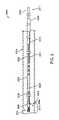
前進するように構成されている。例えば、図1は、カテーテル1014の移動の解剖学的
経路の図を示す。カテーテル1014は、患者の大腿動脈の中に挿入され(例えば、セル
ディンガー法を使用して)、患者の大動脈1050を通って上に前進してもよく、そこか
ら、カテーテルは、頭蓋内動脈瘤などの頭蓋内の標的位置まで頸動脈1060を通って上
に前進してもよく、そこで血管内インプラントは、例えば、動脈瘤を閉塞し、したがって
動脈瘤破裂を予防するために配置されてもよい。送達システムの導管は、このようにして
、本明細書に記載される分離システムを標的位置まで送達するように構成される。いくつ
かの実施形態では、本明細書に記載される送達システムは、導管を含まず、むしろ分離シ
ステムは、標的位置まで直接送達される。The delivery systems described herein include a conduit, such as a conventional catheter or microcatheter, and a detachment system configured to be slidably advanced within the catheter. The catheters of the delivery systems described herein are configured to be advanced through the patient's blood vessels to a target location. For example, FIG. 1 shows a diagram of the anatomical path of travel for
送達システム delivery system
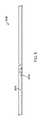
図2は、塞栓用コイルなどの血管内インプラント(図示せず)を送達し配置するための
送達システム2000の例示の実施形態の図を示す。本明細書に記載されるシステム、装
置、及び方法で使用するのに好適なインプラントの他の非限定例としては、例えば、閉塞
コイル及び血管内ステントが挙げられる。FIG. 2 shows a diagram of an exemplary embodiment of a
送達システム2000は、標準カテーテル2014又はマイクロカテーテル(又は他の
導管)などの導管及び分離システム2004を含む。図2に示される例示の実施形態では
、送達システム2000の導管は、カテーテル2014を含む。分離システム2004は
、カテーテル2014内部で摺動自在に位置付けられる(すなわち、前進及び後退する)
ように構成されている細長い本体を含み、いくつかの実施形態では、分離システム200
4は、カテーテル2014を介して、例えば、頭蓋内動脈瘤などの標的位置まで送達され
る。つまり、カテーテル2014を含む送達システムの実施形態では、内部に分離システ
ム2004を有するカテーテル2014は、典型的にはユーザーによって標的位置まで送
達され、標的位置は、例えば頭蓋内動脈瘤、又は例えばアテローム性動脈硬化性の病変を
含み得る。他の実施形態では、分離システム2004は、標的位置まで直接送達される。
In some embodiments, separation system 200 includes an elongated body configured to
4 is delivered via a
分離システム Separation system
分離システム2004は、分離システム2004の異なる機能性エレメントを含むよう
にそれぞれ構成されている近位端2017及び遠位端2016を含む。広くは、分離シス
テム2004の近位端2017は、送達システム2000の使用中、患者の外側にとどま
り、及び分離システム2004の近位端2017は、概してユーザーが手動で分離システ
ム2004を導き、インプラントの配置を制御することができるようにする特徴を含む。
分離システム2004の近位端2017は、送達システム2000のユーザーによって手
動でインプラントを標的位置に配置する機構を提供するように構成されている。広くは、
遠位端2016は、標的位置で血管内インプラントを解放する又は配置するように構成さ
れている分離機構2005、及び分離システム2004がインプラント配置のためにカテ
ーテル2014に対して正しい位置にあるとき、カテーテル2014の遠位端上の放射線
不透過性マーカーと整列するように位置付けられている放射線不透過性マーカー2006
を含む。
A
including.
分離システム2004は、その遠位端2016に分離機構2005を備える。送達シス
テム2000のいくつかの実施形態では、分離システム2004は分離機構を備え、任意
の収縮管2002、任意の接続管2010、任意の膨張管2026、及び任意の握り管2
012を含む一連のそれぞれ任意の相互連結した管を備える細長い本体を形成する。任意
の相互連結した管2002、2010、及び2026、及び2012は、分離システム2
004に異なる品質又は特徴を提供するようにそれぞれ構成されている。収縮管2002
は、ポリマーなどの可撓性材料を含み、血管構造系内の曲がりを通して操作する可撓性を
提供しながら、分離システム2000の遠位端2016の少なくとも一部を覆うかつ/又
は取り巻くように構成されている。収縮管2002はまた、放射線不透過性マーカー20
06と放射線不透過性マーカーカプラー2008との間の機械的連結を介して、放射線不
透過性マーカー2006と分離機構2005との間の密な連結を維持する。接続管201
0は、任意追加的に収縮管2002に接続されてもよく、分離システム2004がカテー
テル2014内部でより容易に前進及び後退するように、遠位端2016(distal 2016
end)及び/又は近位端2017の部分に剛性を提供する比較的剛性の材料(収縮管20
02と比較して)を含む。膨張管2026は、任意追加的に接続管2010に接続され、
セグメントに比較的小さい直径の任意の収縮管2002及び接続管2010と比べて取扱
い易さを提供する拡径(任意の収縮管2002及び接続管2010と比較して)を提供す
る。分離システム2004のいくつかの実施形態では、また膨張管2026は、主要部材
2018の手動後退を容易にすることによって分離機構2005からのインプラントの配
置を容易にする。任意の握り管2012は、ユーザーにハンドグリップを提供し、また分
離システム2004のいくつかの実施形態では、手持ち式分離装置によって置き換えられ
る。接続ワイヤ2011は、分離システムの遠位部分を接続する。
012, forming an elongated body with each optional interconnected tube. Optional
004, each configured to provide different qualities or characteristics. Shrink
comprises a flexible material, such as a polymer, and is configured to cover and/or surround at least a portion of the
06 and the
0 may optionally be connected to shrink
end) and/or a relatively stiff material that provides stiffness to portions of the proximal end 2017 (shrink tube 20
02).
The segment is provided with an enlarged diameter (compared to
送達システム2000のいくつかの実施形態では、分離機構2005は、全体的に例え
ば、ニチノールなどの記憶金属材料を含む。分離システム2004のいくつかの実施形態
では、分離機構2005だけがニチノールなどの記憶金属材料を含む。分離機構2005
のいくつかの実施形態では、(異なる材料を含む)主要部材2018を含まない分離機構
2005は、ニチノールなどの記憶材料を含む。分離機構2005のいくつかの実施形態
では、(異なる材料を含む)放射線不透過性マーカー2006を含まない分離機構200
5は、ニチノールなどの記憶材料を含む。分離機構2005のいくつかの実施形態では、
(異なる材料を含む)主要部材2018及び放射線不透過性マーカー2006を含まない
分離機構2005は、ニチノールなどの記憶材料を含む。In some embodiments of
In some embodiments of ,
5 contains a memory material such as Nitinol. In some embodiments of
分離システム2004の遠位端は、放射線不透過性マーカー2008を含み、カテーテ
ル2014の遠位端は、放射線不透過性マーカー(図示せず)を含む。分離システム20
04の放射線不透過性マーカー2008又はカテーテル上の放射線不透過性マーカーのど
ちらかとして使用するのに好適な金属の非限定例としては、プラチナ、プラチナ-タング
ステン、プラチナイリジウム、銀、又は金などの貴金属又は合金が挙げられる。送達シス
テム2000のいくつかの実施形態では、分離システム2004の放射線不透過性マーカ
ー2008及びカテーテル2014上の放射線不透過性マーカーは、分離機構2005が
配置場所2009に位置付けられるとき互いに整列するように位置付けられる。送達シス
テム2000のいくつかの実施形態では、分離システム2004の放射線不透過性マーカ
ー2008及びカテーテル2014上の放射線不透過性マーカーは、配置場所2009の
約30mm近位の位置で整列するように位置付けられる。The distal end of
Non-limiting examples of metals suitable for use as either the 04
送達システム2000のいくつかの実施形態では、分離システム2004は、放射線不
透過性マーカーの位置で放射線不透過性マーカーカプラー2008を含む。放射線不透過
性マーカーカプラー2008は、放射線不透過性マーカー2006と連結されるように構
成されている分離システム2004の一部である。つまり、分離システム2004の放射
線不透過性マーカー2008は、典型的には例えば、プラチナ、プラチナ-タングステン
、プラチナイリジウム、銀、又は金などの金属を含む。分離機構2005の残りの部分(
いくつかの実施形態以外で主要部材2018ではない)は、ニチノールなどの記憶材料を
含むので、放射線不透過性マーカー2008の分離機構2005への連結は、材料間(す
なわち、放射線不透過性マーカー2008と分離機構2005の記憶材料との間)の違い
のために、溶接などの典型的な方法で容易に達成することができない。そのため、放射線
不透過性マーカーカプラー2008は、放射線不透過性マーカー2006と、2つのエレ
メントを溶接する又は同様に融合する必要なしに機械的に連結するように構成されている
。分離システム2004のいくつかの実施形態では、放射線不透過性マーカーカプラー2
008は、図2に示されるように2つのコンポーネントが嵌合しあって連結するように構
成されている相補的な(complimentary)形状をしている。つまり、分離システム200
4のいくつかの実施形態では、放射線不透過性マーカーカプラー2008は、隆起及び陥
凹あるいは、例えば、鋸歯のパターンによる交互の歯のパターン(示されるように)を有
する分離機構2005のコンポーネントであり、同様に放射線不透過性マーカー2009
は、隆起及び陥凹あるいは、1つのコンポーネントの隆起が相補的コンポーネントの陥凹
に嵌合する、例えば、2つのコンポーネント、放射線不透過性マーカーカプラー2008
及び放射線不透過性マーカーカプラー2009が嵌合しあうような鋸歯のパターンによる
相補的な交互の歯のパターン(示されるように)を有する。分離システム2004のいく
つかの実施形態では、可撓性収縮管2002は、これら2つの結合したコンポーネント、
放射線不透過性マーカーカプラー2008及び放射線不透過性マーカーカプラー2009
を、それらが一緒に固定結合されるように密に取り巻く。In some embodiments of
Since the
008 has a complementary shape configured to mate and connect two components as shown in FIG. That is, separation system 200
4, the
is a ridge and recess, or a ridge of one component fits into a recess of a complementary component, e.g., a two component,
and
, so that they are rigidly bound together.
分離システム2004が塞栓用コイルなどのインプラントを動脈瘤(すなわち、標的)
内に適切に配置するために、分離機構2005をカテーテル2014に沿って配置場所2
013まで前進させる必要がある。配置場所2013は、配置されるインプラントのタイ
プに応じてカテーテル2014に沿った異なる場所であってもよい。例えば、送達システ
ム2000のいくつかの実施形態では、動脈瘤又は他の標的位置内での塞栓用コイル又は
他のインプラントの適切な配置のために、塞栓用コイル又は他のインプラントは、カテー
テル2014の開口部2009から外に完全に前進する。例えば、送達システム2000
のいくつかの実施形態では、動脈瘤又は他の標的位置内での塞栓用コイル又は他のインプ
ラントの適切な配置のために、塞栓用コイルは、カテーテル2014の開口部2009か
ら外に部分的に前進する。例えば、送達システム2000のいくつかの実施形態では、動
脈瘤又は他の標的位置内での塞栓用コイル又は他のインプラントの適切な配置のために、
分離機構は、カテーテル2014の開口部2009から外に完全に前進する。送達システ
ム2000のいくつかの実施形態では、動脈瘤又は他の標的位置内での塞栓用コイル又は
他のインプラントの適切な配置のために、分離機構2005は、カテーテルの開口部20
09から外に部分的に前進する。図2に示される例示の実施形態に示されるように、例示
した実施形態における分離機構2005は、インプラントの適切な配置のためにカテーテ
ル2014の遠位部分内部に位置付けられ、したがって図2に示される実施形態において
配置場所2013は、カテーテル2014の遠位端に位置する。A
It must advance to 013.
In some embodiments of , the embolic coil is partially out of the
The detachment mechanism is fully advanced out of opening 2009 of
Partially advance out of 09. As shown in the exemplary embodiment shown in FIG. 2, the
つまり、図2に示されるように、カテーテルの遠位端2016は、インプラントの良好
な配置を実現するために分離システム2004(及びしたがって分離システムの遠位端に
おける分離機構2005)が前進する必要がある位置又は領域である配置場所2013を
画定する。例えば、インプラントの適切な配置を実現するために、分離システム2004
がカテーテル2014の遠位端内部に全体的に残る送達システムの実施形態において、配
置場所2013は、分離システム2004がカテーテルの遠位端2016内部に位置付け
られている位置にある。例えば、インプラントの適切な配置を実現するために、分離シス
テム2004がカテーテルの遠位端2016で部分的に開口部2009の外にあり、部分
的にカテーテルの遠位端2016内部にある送達システムの実施形態において、分離シス
テム2004が位置付けられている配置場所は、部分的に開口部2009の外側、かつ部
分的にカテーテル内部に位置する。例えば、インプラントの適切な配置を実現するために
、分離システム2004が完全に開口部2009の外にある送達システムの実施形態にお
いて、配置場所は、分離システム2004がカテーテルの外側に位置付けられている位置
にある。That is, as shown in FIG. 2, the
remains entirely within the distal end of the
広くは、カテーテル2002の近位端2017は、標的までのインプラントの前進及び
標的での又は標的内のインプラントの配置に対する手動操作をユーザーにもたらす1つ以
上の特徴部と結合されている。送達システム2000のいくつかの実施形態では、カテー
テル2002の近位端2017は、膨張管2026と結合されている。膨張管2026は
、マイクロカテーテル2002の比較的小さな直径より大きな直径を有するように構成さ
れている。膨張管2026は、通常、送達システム2000を他のエレメントに結合でき
るように構成されている。例えば、送達システム2000のいくつかの実施形態では、膨
張管2026は、握り管2012に送達システム2000の最近位端2017で結合する
。握り管2012は、患者の血管構造を通して分離システムをガイドするために分離シス
テムを前進及び/又は後退させる手動把持部を、ユーザーに提供する。送達システム20
00のいくつかの実施形態では、膨張管2026は、膨張管2026を分割するように、
膨張管2026の手動破壊を容易にするためにその材料内に1つ以上の楕円形の切り込み
又は破断部を含む。膨張管2026を手動で分割することは、膨張管2026の破砕部分
を分離システムから離れて近位の方向に後退させるための機構を提供し、その機構は送達
システム2000のいくつかの実施形態で使用されてインプラントの配置を手動によりト
リガする。送達システム2000のいくつかの実施形態では、膨張管2026は、分離シ
ステム2004を使用してインプラントの配置を手動でトリガするように構成されている
外部分離装置と結合する。In general,
00, the
Including one or more elliptical cuts or breaks in the material to facilitate manual breaking of the
分離機構 Separation mechanism
本明細書に記載のシステム、装置、及び方法のいくつかの実施形態では、分離機構20
05は、分離システム2004の遠位端2016に位置付けられ、分離システム2004
は、カテーテル2014と共に送達システム2000を形成する。In some embodiments of the systems, devices, and methods described herein, separation mechanism 20
05 is positioned at the
いくつかの実施形態では、分離機構2005は、主要部材2018、アンカー部材、及
びタブを含み、これらは血管内インプラントの解放及び/又は配置をもたらす分離機構2
005を作動させるように構成され位置付けられている。In some embodiments, the
005.
図2に示されるように主要部材2018は、いくつかの実施形態において機構2005
の配置が配置場所2009にあるとき、送達システム2000の長さにわたり延在するの
に十分な長さであるように構成されている。
is configured to be of sufficient length to extend the length of
分離機構2005の実施形態の多く追加の特徴部は、ここで図3を追加参照するととも
に、図2を更に参照して説明される。Many additional features of an embodiment of
図3は、分離機構3005と取り外し可能に結合されている塞栓用コイル3022(又
は他のインプラント)を含む分離機構3005の例示の実施形態の図を示す。FIG. 3 shows a view of an exemplary embodiment of a
分離機構3005は、血管内インプラント3022の配置をもたらすように構成されて
いるエレメントを含む。いくつかの実施形態では、分離機構3005は、タブ3016、
任意の主要部材3018、及び任意のアンカー要素3020を含む。
Optional
分離機構3005のタブ3016は、少なくとも2つの構成又は位置、少なくとも第1
の構成又は位置及び第2の構成又は位置を有するように構成される。タブ3016の第1
の構成又は位置において、塞栓用コイル3022は、タブ3016によって保持される又
はタブ3016と結合され、タブ3016の第2の構成又は位置において、塞栓用コイル
3022を解放するか又は塞栓用コイル3022から分離する。分離システムのいくつか
の実施形態では、タブ3016は、ハウジング3024の一部又はハウジング3024と
一体のどちらかである。送達システム3000のいくつかの実施形態では、タブ3016
は、記憶金属又はニチノールなどの他の記憶材料を含む。ハウジング3024は、塞栓用
コイル3022、及びいくつかの実施形態では塞栓用コイル3022と結合されるアンカ
ー要素3020の少なくとも一部を含むように構成されている。
and a second configuration or position. The first of
In a second configuration or position of
includes memory metals or other memory materials such as nitinol.
分離機構3005のいくつかの実施形態では、分離機構3005のタブ3016は、主
要部材3018の遠位部分と取り外し可能に結合する。これらの実施形態では、主要部材
3018と結合された状態で、タブ3016は、第1の位置にあり、タブ3016は、ハ
ウジング3024の内側に向かって押圧されるか又は曲がっている。タブ3016は、第
1の位置でハウジング3024の内側に向かって曲がっているとき、少なくとも部分的に
ハウジング3024内部にある塞栓用コイル3022と直接結合するか、又はいくつかの
実施形態では、いくつかの実施形態で塞栓用コイル3022と結合されるアンカー要素3
020と結合することにより塞栓用コイル3022と間接的に結合するかのどちらかであ
るように位置付けられる。第1の位置にあるタブ3016に結合することにより、塞栓用
コイル3022は、分離システム3016のハウジング3024内部に保持される。In some embodiments of
020 to indirectly couple with the
分離機構3005のいくつかの実施形態では、塞栓用コイル3022(又は他の血管内
インプラント)は、タブ3016と結合されるように構成されているアンカー要素302
0と結合される。これらの実施形態において、アンカー要素は、タブ3016が第1の位
置にあってハウジングの内側に向かって曲がっているとき、タブ3016に取り外し可能
に結合するように構成されている。例えば、送達システム3000のいくつかの実施形態
では、図3に示されるように、アンカー要素3020は、球体又はボールを含み、またタ
ブ3016が第1の位置にあるとき、ボール3020がハウジング3024内部に保持さ
れて、したがって塞栓用コイル3022が分離機構3014によって保持されるようにボ
ール3020を引っかける又は留め具で留める。In some embodiments of
Combined with 0. In these embodiments, the anchor element is configured to removably couple to
主要部材3018を含む分離機構3005の実施形態では、主要部材は、タブ3016
と結合されるとき、タブ3016がハウジング3024の内側に向かって曲がるように、
タブ3016の第1の位置にタブ3016を保持する。これらの実施形態において、例え
ば、近位の方向に後退することによって主要部材3018がタブから分離されるとき、タ
ブ3016は、ハウジング3024の内側から離れる方向に移動して第2の位置まで移動
する。タブ3016が記憶材料を含む実施形態において、タブ3016の材料は、主要部
材3018から分離されるとき、ハウジング3024の内側から離れる方向へのタブ30
16の移動を容易にする。システム3000のいくつかの実施形態では、主要部材は、分
離システムが例えば、頭蓋内動脈瘤などの標的位置の近くに位置付けられたとき、ユーザ
ーにより近位に後退する。主要部材3018は、例えば、カテーテル3002の近位端3
017から外に、ユーザーがワイヤを近位に引っ張り、したがって主要部材3018及び
タブ3016を分離することができる位置まで延在するワイヤを含んでもよい。In embodiments of
so that
Facilitates 16 movement. In some embodiments of system 3000, the primary member is proximally retracted by the user when the isolation system is positioned near a target location, such as an intracranial aneurysm. The
There may be a wire extending out from 017 to a position where the user can pull the wire proximally, thus separating
分離システム3004のいくつかの実施形態では、膨張管3026は、膨張管3026
の少なくとも一部が分離システムの残りから離れる近位の方向に後退し得るように、破砕
するように構成されている。これらの実施形態のいくつかにおいて、主要部材3018は
、膨張管3026と結合され、その結果膨張管3026が破砕され、近位の方向に後退す
るとき、主要部材3018は、タブ3016から分離され、その結果タブ3016は、第
1の位置から第2の位置まで移動し、塞栓用コイル3022の解放をもたらす。送達シス
テム3000のいくつかの実施形態では、主要部材3018は、分離システムの長さにわ
たり、手持ち式分離装置の方へ延在するワイヤを含む。これらの実施形態において、手持
ち式分離装置は、主要部材3018を把持し、近位の方向に後退させて、したがって主要
部材3018をタブ3016から分離するように構成されている手動で操作されるクラン
プを含み、その結果タブ3016は、第1の位置から第2の位置まで移動し、塞栓用コイ
ル3022の解放をもたらす。In some embodiments of isolation system 3004, expansion tube 3026 is
is configured to fracture such that at least a portion of the can be retracted in a proximal direction away from the remainder of the isolation system. In some of these embodiments, the
図4は、どのように血管内インプラントが分離システム4014から配置されるかを示
す分離機構4005の遠位端の実施形態の図を示す。図2を参照して説明されるように、
タブ4016は、少なくとも第1の位置及び第2の位置を有する。タブ4016の第2の
位置において、図4に示されるようにタブ4016は、ハウジング4024の内側に向か
って曲がるのではなく、むしろハウジング4024の内側から離れる方向に位置するよう
に位置付けられている。主要部材4018は、タブ4016から離れる方向に後退して、
したがって分離されている状態で示される。そのため、アンカー要素4020は、分離シ
ステム4014によってもはや保持されず、塞栓用コイル(図4に図示せず)は、標的位
置に解放又は配置される。FIG. 4 shows a view of a distal end embodiment of
They are therefore shown in isolation. As such, the
膨張管 expansion tube
図5は、膨張管5026の実施形態の例示の図を示す。図1及び図2を参照して説明さ
れるように、分離システムのいくつかの実施形態は、システムの近位端2017に膨張管
5026を含む。これらの実施形態のいくつかにおいて、膨張管5026は、切り込み5
030が、ユーザーにより膨張管5026に曲げが加えられたとき膨張管5026の破砕
を容易にするように位置付けられかつ/又は構成されるように、膨張管5026の直径を
少なくとも部分的に取り巻く1つ以上の切り込み5030を含む。膨張管5026内部の
主要部材5018もまた図5に示される。送達システム2000のいくつかの実施形態で
は、膨張管5026は、その近位端2017で、ユーザーがカテーテルの前進及び後退を
制御するとともにインプラントの手動配置を制御することを可能にするように構成されて
いるハンドグリップ(図5には図示せず)に更に結合され得る。図1~図2を参照して説
明されるように、主要部材5018は、分離システムのいくつかの実施形態において、膨
張管5026又はハンドグリップのどちらかに接続されている。膨張管5026が破砕さ
れると、膨張管5026の破砕された部分(及びハンドグリップを伴ういくつかの実施形
態)は、カテーテルから離れて近位の方向に後退することができる。分離システムのいく
つかの実施形態では、分離システムを互いから引き離すことができる遠位部分と近位部分
とに分けるように膨張管5026が破砕されると、主要部材5016はもはやタブ201
6に保持されず、その結果、タブは、(記憶材料によって容易にされた)第2の位置まで
移動し、力を主要部材5016に及ぼして主要部材5016を近位に押し出す。FIG. 5 shows an exemplary view of an embodiment of an
030 at least partially surrounds the diameter of
6, so that the tab moves to a second position (facilitated by the memory material) and exerts a force on primary member 5016 to push primary member 5016 proximally.
手持ち式分離装置 handheld separator
図6A~図6Bは、手持ち式分離装置6032を使用して血管内インプラントを手動で
配置するための代替の機構の図を示す。図6Aは、ハウジング6034及びアクチュエー
タスイッチ6036を含む手持ち式分離装置6032の斜視図を示す。例示の実施形態に
おいて、手持ち式分離装置6032の内側に入るワイヤを含む、主要部材6018もまた
示されている。図6A~図6Bには示されないが、分離システムの近位端2017に位置
する手持ち式分離装置6032は、ユーザーが手動で主要部材6018を近位の方向に後
退させ、したがって説明したようにインプラントを配置することができるように構成され
ている。図6Bは、バネ6040と共にカムクランプ6038a及び6038bを含む手
持ち式分離装置6032の断面図を示す。手術中、ユーザーは、クランピングカム603
8a及び6038bを近位の方向に後退させるアクチュエータ6036を係合する。送達
システム2000のいくつかの実施形態では、クランピングカムは、これらの実施形態に
おいて主要部材に接続されている送達装置2000の遠位端2016で握り管を把持し、
その結果、クランピングカム6038a及び6038bが近位の方向に後退するとき、主
要部材も同様に近位の方向に後退し、説明されたように第1の位置から第2の位置へのタ
ブの変化をもたらす。バネ6040は、クランピングカム6038a及び6038bの不
用意な作動、及びしたがって血管内インプラントの不用意な配置を防ぐための抵抗を提供
する。FIGS. 6A-6B show views of an alternative mechanism for manually placing an endovascular implant using a
As a result, when the
図7は、送達システム7000の握り管7012を把持するクランピングカム7038
a及び7038bを示す手持ち式分離装置6032の断面図のクローズアップの図を示す
。クランピングカム7038a及び7038bは、アクチュエータスイッチ7036によ
って作動され、このことは、例えば、ユーザーにより近位の方向に摺動されることによっ
てクランピングカム(clamping camps)7038a及び7038bの近位の移動をもたら
す。手持ち式分離装置7032のいくつかの実施形態では、アクチュエータスイッチ70
36は、クランピングカム7038a及び7038bに、握り管7012の把持及び近位
の移動の両方を行わせる。これらの実施形態において、アクチュエータスイッチ7036
が主要部材の不用意な後退を防ぐための安全機能として係合されるとき、クランピングカ
ム7038a及び7038bは、握り管7012の把持のみを行う。FIG. 7 shows the clamping cam 7038 gripping the
7038b shows a close-up view of a cross-sectional view of the
36
Clamping
図8a~図8Bは、視界窓8042内にユーザーが見るものの図を示し、視界窓804
2は、記載される手持ち式分離装置のいくつかの実施形態の特徴部である。視界窓804
2は、ユーザーに、握り管8012が手持ち式分離装置によって近位に後退したという目
視確認を表示するように構成されている。図8Aでは、視界窓8042は、握り管801
2が近位の方向に後退していないこと、及び主要部材がしたがって分離システムのタブと
結合されていることを示す膨張管8024及び握り管8012を表示する。図8Bでは、
視界窓8042は、握り管8012が近位の方向に後退したこと、及び主要部材が分離シ
ステムのタブから分離されていることを示す膨張管8024のみを表示する。8a-8b show views of what the user sees in
2 is a feature of some embodiments of the handheld separation device described. view window 804
2 is configured to display to the user a visual confirmation that the
2 are not retracted in the proximal direction, and the inflation tube 8024 and
A
本明細書に記載のシステムの実施形態のいずれかを使用して、血管内インプラントを標
的位置に配置するための例示の方法の工程は、次のとおりである:ユーザーに、カテーテ
ル2002及び分離システム2004を含む図2に示される送達システム2000を提供
すること。Exemplary method steps for placing an endovascular implant at a target location using any of the system embodiments described herein are as follows: User instructs
本明細書に記載のシステムの実施形態のいずれかを使用して、血管内インプラントを標
的位置に配置するための例示の方法の工程は、次のとおりである:カテーテル2002及
び分離システム2004を含む図2に示される送達システム2000を受容すること。頭
蓋内動脈瘤などの解剖学的標的位置まで送達システム2000を前進させること。カテー
テル2002内部で分離システム2014を前進させ、その結果インプラントが標的位置
の中に前進すること(すなわち、塞栓用コイルが動脈瘤内部に前進する)。カテーテル上
の第1の放射線不透過性マーカー及び分離システム2014の第2の放射線不透過性マー
カーの配置をX線撮影で可視化することによって、分離システム2014が分離場所にあ
ることを判定すること。代替的に又は追加的に、カテーテル2002及び分離システム2
014を第1の放射線不透過性マーカーの場所で連結する連動システムによってもたらさ
れる分離システム2014の更なる前進に対する抵抗を検知することによって、分離シス
テム2014が分離場所にあることを判定すること。代替的に又は追加的に、手持ち式分
離装置の視界窓内に可視の握り管がないことを見て分離システム2014が分離場所にあ
ることを判定すること。Exemplary method steps for placing an endovascular implant at a target location using any of the system embodiments described herein are as follows:
Determining that the
本明細書に記載のシステムの実施形態のいずれかを使用して、血管内インプラントを標
的位置に配置するための例示の方法の工程は、次のとおりである:分離システムのタブか
らの主要部材の後退によって、塞栓用コイル又は塞栓用コイルと連結されたアンカー要素
に連結される第1の位置から、タブが塞栓用コイル又はアンカー要素のどちらかから分離
することによって塞栓用コイルを配置する第2の位置まで、タブを移動させること。Exemplary method steps for placing an endovascular implant at a target location using any of the system embodiments described herein are as follows: Primary member from tab of detachment system deploying the embolic coil by separating the tab from either the embolic coil or the anchor element from the first position where it is connected to the embolic coil or the anchor element connected to the embolic coil by retraction of the Move the tab to position 2.
本発明の上記の説明は、例示及び説明の目的のために示されている。本発明を開示され
た正確な形態で網羅すること又は限定することは意図されておらず、上述の教示を考慮す
れば他の改変及び変更例が可能であり得る。本実施形態は、それによって当業者が想到さ
れる特定の用途に適するように様々な実施形態及び様々な改変で本発明を最も良く利用で
きるようにするため、本発明の原理及びその実用的応用を最も良く説明するように選択し
、記述した。添付の「特許請求の範囲」が、先行技術によって限定される場合を除いて本
発明の他の代替の実施形態を含むように解釈されることが意図されている。The foregoing description of the invention has been presented for purposes of illustration and description. It is not intended to be exhaustive or to limit the invention to the precise forms disclosed, and other modifications and variations are possible in light of the above teachings. The present embodiments are intended to illustrate the principles of the invention and its practical applications, thereby enabling the invention to best be utilized in various embodiments and various modifications as are suitable for the particular applications contemplated by those skilled in the art. selected and described to best illustrate the It is intended that the appended claims be interpreted to include other alternative embodiments of the invention except as limited by the prior art.
Claims (18)
Translated fromJapanesei.前記塞栓用コイルが配置される配置場所及び第1の放射線不透過性マーカーを有す
る導管と、
ii.前記導管内部に収まり、かつ前記導管内部で摺動自在に前進及び後退するように
構成されている分離システムであって、
c.
1.記憶材料を含み、第1の位置及び第2の位置を有するタブであって、前記記憶
材料が、前記第1の位置から前記第2の位置まで前記タブを移動させるように構成されて
いるタブと、
2.前記タブが、主要部材に係合されるとき前記第1の位置にあり、前記主要部材
が前記タブにもはや係合されなくなったとき前記記憶材料によって前記第2の位置まで移
動するように、前記タブと係合するよう構成され位置付けられている主要部材と、
3.前記塞栓用コイルと連結され、かつ前記タブが前記第1の位置にあるとき前記
塞栓用コイルが前記分離システムと連結されるように、前記第1の位置で前記タブと係合
するよう構成され位置付けられているアンカー要素であって、前記アンカー機構は、前記
タブが前記第2の位置にあるとき前記塞栓用コイルが配置されるように前記第2の位置で
前記タブと係合しないよう構成され位置付けられている、アンカー要素と、
4.放射線不透過性マーカーカプラーと、を含む分離機構と、
d.前記放射線不透過性マーカーカプラーと機械的に連結され、前記分離機構が配置
場所に位置付けられるとき前記第1の放射線不透過性マーカーと整列するように位置付け
られている第2の放射線不透過性マーカーと、を含む分離システムと、を含む塞栓用コイ
ル送達システム。An embolic coil delivery system for delivering and positioning an embolic coil in an aneurysm, comprising:
i. a conduit having a placement site in which the embolic coil is placed and a first radiopaque marker;
ii. a separation system configured to fit within said conduit and to be slidably advanced and retracted within said conduit, comprising:
c.
1. A tab comprising a memory material and having a first position and a second position, wherein the memory material is configured to move the tab from the first position to the second position. When,
2. said tab being in said first position when engaged with a primary member and moved by said storage material to said second position when said primary member is no longer engaged with said tab; a primary member configured and positioned to engage the tab;
3. coupled with the embolic coil and configured to engage the tab at the first position such that the embolic coil is coupled with the separation system when the tab is in the first position; A positioned anchor element, wherein the anchor mechanism is configured not to engage the tab in the second position such that the embolic coil is positioned when the tab is in the second position. an anchor element positioned at the
4. a detachment mechanism comprising a radiopaque marker coupler;
d. A second radiopaque marker mechanically coupled to the radiopaque marker coupler and positioned to align with the first radiopaque marker when the detachment mechanism is positioned at the deployment location. and a detachment system, and an embolic coil delivery system.
ラー及び前記放射線不透過性マーカーを固定連結する可撓性管を含む、請求項1に記載の
システム。2. The system of claim 1, wherein the detachment system comprises a flexible tube surrounding the detachment system and fixedly connecting the radiopaque marker coupler and the radiopaque marker.
1の放射線不透過性マーカーが前記第2の放射線不透過性マーカーと整列するように、前
記導管を部分的に取り巻き、前記第2の放射線不透過性マーカーは、X線撮影で視認でき
る、請求項1に記載のシステム。The first radiopaque marker advances the conduit such that the separation mechanism is advanced within the conduit and the first radiopaque marker is aligned with the second radiopaque marker. 2. The system of claim 1, wherein the partially encircling second radiopaque marker is radiographically visible.
前記主要部材及び前記タブが連結されているとき、前記タブが前記第1の位置にあり、前
記主要部材及び前記タブが分離されているとき、前記タブが前記第2の位置まで移動する
、請求項4に記載のシステム。the decoupling mechanism further includes a primary member that removably couples to the tab, so that:
wherein said tab is in said first position when said main member and said tab are connected, and said tab moves to said second position when said main member and said tab are separated. Item 5. The system according to item 4.
る、請求項5に記載のシステム。6. The system of claim 5, wherein the tab moves to the second position when the primary member is pulled away from the tab.
メントを含み、前記主要部材は、前記セグメントと連結され、その結果、前記セグメント
が手動で前記分離システムから分離され、かつ離れる方向に後退するとき、前記主要部材
は前記タブから引き離され、その結果、前記タブは前記第2の位置まで移動し、前記コイ
ルを配置する、請求項6に記載のシステム。wherein the separation system includes a segment configured to be manually separated from the separation system, the primary member is coupled with the segment such that the segment is manually separated from the separation system, and 7. The system of claim 6, wherein when retracting away, the primary member is pulled away from the tab so that the tab moves to the second position and deploys the coil.
ように構成されている楕円形の切り込みを、その外径の周囲に含む、請求項7に記載のシ
ステム。8. The system of claim 7, wherein the segment includes an elliptical cut around its outer diameter configured to fracture the segment when a bending force is applied to the segment.
引き離されるように、前記主要部材をクランプするように構成されている手持ち式分離装
置と連結され、前記把持部は、前記主要部材が前記タブから引き離されるときにそれを示
す視界窓を含む、請求項7に記載のシステム。The primary member is coupled to a hand-held detachment device configured to clamp the primary member such that the primary member is pulled away from the tab when the gripper is pulled away from the conduit, the gripping portion 8. The system of claim 7, including a viewing window to indicate when the primary member is pulled away from the tab.
患者の1つ以上の血管を通して前記動脈瘤まで導管を導くことであって、前記導管が、
第1の放射線不透過性マーカーと、配置場所とを含む、ことと、
前記導管が前記血管内部にある間に前記導管を通して分離システムを前進させることで
あって、前記分離システムが、放射線不透過性マーカーカプラーと、第2の放射線不透過
性マーカーと、第1の位置及び第2の位置を有するタブを含む分離機構と、を含むことと
、
前記分離システムを使用して前記動脈瘤内に前記塞栓用コイルを配置することと、を含
み、
前記放射線不透過性マーカーカプラー及び前記第2の放射線不透過性マーカーは、機械
的に連結し、
前記分離機構が前記配置場所に位置付けられているとき、前記第1の放射線不透過性マ
ーカー及び前記第2の放射線不透過性マーカーが整列し、
前記塞栓用コイルがアンカー要素と連結され、
前記タブが前記第1の位置にあるとき、前記アンカー要素は、前記タブに係合し、した
がって前記塞栓用コイルを前記分離システムに連結し、
前記アンカー要素は、前記第2の位置で前記タブに係合せず、したがって前記塞栓用コ
イルを前記分離システムから分離し、結果として前記塞栓用コイルを前記頭蓋内動脈瘤に
配置する、方法。A method for placing an embolic coil in an intracranial aneurysm comprising:
guiding a conduit through one or more vessels of a patient to the aneurysm, the conduit comprising:
including a first radiopaque marker and a placement location;
advancing a separation system through the conduit while the conduit is inside the blood vessel, the separation system including a radiopaque marker coupler, a second radiopaque marker, and a first position; and a separation mechanism including a tab having a second position;
positioning the embolic coil within the aneurysm using the isolation system;
the radiopaque marker coupler and the second radiopaque marker are mechanically coupled;
the first radiopaque marker and the second radiopaque marker are aligned when the separation mechanism is positioned at the deployment location;
the embolic coil is coupled with an anchor element;
when the tab is in the first position, the anchor element engages the tab, thus coupling the embolic coil to the detachment system;
The method wherein the anchor element does not engage the tab in the second position, thus separating the embolic coil from the separation system, resulting in placement of the embolic coil in the intracranial aneurysm.
ラー及び前記放射線不透過性マーカーを固定連結する可撓性管を含む、請求項10に記載
の方法。11. The method of claim 10, wherein the separation system comprises a flexible tube surrounding the separation system and fixedly connecting the radiopaque marker coupler and the radiopaque marker.
記第1の放射線不透過性マーカーが前記第2の放射線不透過性マーカーと整列するように
、前記導管を部分的に取り巻き、前記第2の放射線不透過性マーカーは、X線撮影で視認
できる、請求項10に記載の方法。The first radiopaque marker advances the conduit such that the separation system is advanced within the conduit and the first radiopaque marker is aligned with the second radiopaque marker. 11. The method of claim 10, wherein the partially encircling second radiopaque marker is radiographically visible.
前記主要部材及び前記タブが連結されているとき、前記タブが前記第1の位置にあり、前
記主要部材及び前記タブが分離されているとき、前記タブが前記第2の位置まで移動する
、請求項13に記載の方法。the decoupling mechanism further includes a primary member that removably couples to the tab, so that:
wherein said tab is in said first position when said main member and said tab are connected, and said tab moves to said second position when said main member and said tab are separated. Item 14. The method according to item 13.
を前記タブから分離することを含む、請求項14に記載の方法。15. The method of claim 14, wherein the disposing step includes separating the primary member from the tab by pulling the primary member away from the tab.
記主要部材は、前記セグメントと連結され、その結果、前記セグメントが手動で前記導管
から分離され、かつ離れる方向に後退するとき、前記主要部材は前記タブから引き離され
、その結果、前記タブは前記第2の位置まで移動し、前記塞栓用コイルを配置する、請求
項15に記載の方法。The conduit includes a segment configured for manual separation from the conduit, the primary member being coupled with the segment such that the segment is manually separated from the conduit and moved away from the conduit. 16. The method of claim 15, wherein when retracted, the primary member is pulled away from the tab such that the tab moves to the second position and deploys the embolic coil.
ように構成されている楕円形の切り込みを、その外径の周囲に含む、請求項16に記載の
方法。17. The method of claim 16, wherein the segment includes an elliptical cut around its outer diameter configured to fracture the segment when a bending force is applied to the segment.
から引き離されるように、前記主要部材をクランプするように構成されている手持ち式分
離装置と連結され、前記把持部は、前記主要部材が前記タブから引き離されるときにそれ
を示す視界窓を含む、請求項16に記載の方法。said primary member coupled to a hand-held disconnect device configured to clamp said primary member such that said primary member is pulled away from said tab when said gripper is pulled away from said conduit; 17. The method of claim 16, wherein includes a viewing window that indicates when the primary member is pulled away from the tab.
Applications Claiming Priority (6)
| Application Number | Priority Date | Filing Date | Title |
|---|---|---|---|
| US201662343542P | 2016-05-31 | 2016-05-31 | |
| US201662343528P | 2016-05-31 | 2016-05-31 | |
| US15/410,639 | 2017-01-19 | ||
| US15/410,639US10531876B2 (en) | 2016-05-31 | 2017-01-19 | Systems and methods for delivering intravascular implants |
| PCT/US2017/040425WO2017210705A1 (en) | 2016-05-31 | 2017-06-30 | Systems and methods for delivering intravascular implants |
| JP2018560453AJP7123811B2 (en) | 2016-05-31 | 2017-06-30 | Systems and methods for delivering intravascular implants |
Related Parent Applications (1)
| Application Number | Title | Priority Date | Filing Date |
|---|---|---|---|
| JP2018560453ADivisionJP7123811B2 (en) | 2016-05-31 | 2017-06-30 | Systems and methods for delivering intravascular implants |
Publications (1)
| Publication Number | Publication Date |
|---|---|
| JP2022166150Atrue JP2022166150A (en) | 2022-11-01 |
Family
ID=60420781
Family Applications (2)
| Application Number | Title | Priority Date | Filing Date |
|---|---|---|---|
| JP2018560453AActiveJP7123811B2 (en) | 2016-05-31 | 2017-06-30 | Systems and methods for delivering intravascular implants |
| JP2022127706APendingJP2022166150A (en) | 2016-05-31 | 2022-08-10 | Systems and methods for delivering intravascular implants |
Family Applications Before (1)
| Application Number | Title | Priority Date | Filing Date |
|---|---|---|---|
| JP2018560453AActiveJP7123811B2 (en) | 2016-05-31 | 2017-06-30 | Systems and methods for delivering intravascular implants |
Country Status (5)
| Country | Link |
|---|---|
| US (1) | US10531876B2 (en) |
| EP (1) | EP3463544A4 (en) |
| JP (2) | JP7123811B2 (en) |
| CN (1) | CN109195657B (en) |
| WO (1) | WO2017210705A1 (en) |
Families Citing this family (7)
| Publication number | Priority date | Publication date | Assignee | Title |
|---|---|---|---|---|
| US10531876B2 (en) | 2016-05-31 | 2020-01-14 | Spartan Micro, Inc. | Systems and methods for delivering intravascular implants |
| US9968360B2 (en)* | 2016-05-31 | 2018-05-15 | Spartan Micro, Inc. | Systems and methods for delivering intravascular implants |
| US10390982B1 (en) | 2018-11-13 | 2019-08-27 | Icad Endovascular Llc | Systems and methods for delivery retrievable stents |
| US12090072B2 (en) | 2018-11-13 | 2024-09-17 | Icad Endovascular Llc | Systems and methods for delivery retrievable stents |
| CN110840650B (en)* | 2019-11-14 | 2022-08-26 | 镇江市第一人民医院 | Lacrimal duct embolism introducer |
| CN111888062B (en)* | 2020-08-24 | 2021-06-25 | 北京泰杰伟业科技有限公司 | Blood flow guiding device conveying system capable of visually tracking and positioning and tracking and positioning method |
| CN119112274B (en)* | 2023-11-28 | 2025-03-14 | 无锡市第二人民医院 | Embolic microcatheter with releasable head end and method |
Citations (15)
| Publication number | Priority date | Publication date | Assignee | Title |
|---|---|---|---|---|
| JPH08289934A (en)* | 1995-04-20 | 1996-11-05 | Kanegafuchi Chem Ind Co Ltd | Catheter for expanding medical balloon |
| JP2006521161A (en)* | 2003-03-26 | 2006-09-21 | カーディオマインド インコーポレイティッド | Implant delivery technology |
| US20060276823A1 (en)* | 2005-06-02 | 2006-12-07 | Vladimir Mitelberg | Embolic coil delivery system with mechanical release mechanism |
| JP2007160111A (en)* | 2005-12-14 | 2007-06-28 | Cordis Neurovascular Inc | Stretch-resistant embolic coil delivery system with mechanical release mechanism |
| US20070239196A1 (en)* | 2006-04-06 | 2007-10-11 | Pomeranz Mark L | Heat Detachable Coil |
| US20080045997A1 (en)* | 2005-06-02 | 2008-02-21 | Keith Balgobin | Stretch resistant embolic coil delivery system with mechanical release mechanism |
| US20080269675A1 (en)* | 2007-04-27 | 2008-10-30 | Keith Balgobin | Interventional medical device system having a slotted section and radiopaque marker and method of making the same |
| JP2009533202A (en)* | 2006-04-17 | 2009-09-17 | マイクロ セラピューティクス, インコーポレイテッド | System and method for mechanically positioning an endovascular implant |
| US20090312748A1 (en)* | 2008-06-11 | 2009-12-17 | Johnson Kirk L | Rotational detachment mechanism |
| JP2010521232A (en)* | 2007-03-13 | 2010-06-24 | マイクロ セラピューティクス, インコーポレイテッド | Implant, mandrel, and implant formation method |
| JP2011000469A (en)* | 2002-12-03 | 2011-01-06 | Boston Scientific Ltd | Composite medical instrument with marker |
| JP2015518752A (en)* | 2012-05-31 | 2015-07-06 | ベイリス メディカル カンパニー インコーポレイテッドBaylis Medical Company Inc. | Radio frequency punching device |
| US20160228126A1 (en)* | 2015-02-06 | 2016-08-11 | Boston Scientific Scimed, Inc. | Occlusion device |
| JP2016174709A (en)* | 2015-03-19 | 2016-10-06 | テルモ株式会社 | Balloon catheter |
| JP2016179029A (en)* | 2015-03-24 | 2016-10-13 | テルモ株式会社 | catheter |
Family Cites Families (29)
| Publication number | Priority date | Publication date | Assignee | Title |
|---|---|---|---|---|
| US6296622B1 (en) | 1998-12-21 | 2001-10-02 | Micrus Corporation | Endoluminal device delivery system using axially recovering shape memory material |
| US6277125B1 (en) | 1998-10-05 | 2001-08-21 | Cordis Neurovascular, Inc. | Embolic coil deployment system with retaining jaws |
| US20040193179A1 (en) | 2003-03-26 | 2004-09-30 | Cardiomind, Inc. | Balloon catheter lumen based stent delivery systems |
| US7799052B2 (en) | 2005-06-02 | 2010-09-21 | Codman & Shurtleff, Inc. | Stretch resistant embolic coil delivery system with mechanical release mechanism |
| US7367987B2 (en) | 2005-06-02 | 2008-05-06 | Cordis Neurovascular, Inc. | Stretch resistant embolic coil delivery system with mechanical release mechanism |
| US7819891B2 (en) | 2005-06-02 | 2010-10-26 | Codman & Shurtleff, Inc. | Stretch resistant embolic coil delivery system with spring release mechanism |
| US20060276833A1 (en) | 2005-06-02 | 2006-12-07 | Keith Balgobin | Stretch resistant embolic coil delivery system with spring assisted release mechanism |
| US7819892B2 (en) | 2005-06-02 | 2010-10-26 | Codman & Shurtleff, Inc. | Embolic coil delivery system with spring wire release mechanism |
| US7371251B2 (en) | 2005-06-02 | 2008-05-13 | Cordis Neurovascular, Inc. | Stretch resistant embolic coil delivery system with mechanical release mechanism |
| US7985238B2 (en) | 2005-06-02 | 2011-07-26 | Codman & Shurtleff, Inc. | Embolic coil delivery system with spring wire release mechanism |
| US7371252B2 (en) | 2005-06-02 | 2008-05-13 | Cordis Neurovascular, Inc. | Stretch resistant embolic coil delivery system with mechanical release mechanism |
| US7811305B2 (en) | 2005-06-02 | 2010-10-12 | Codman & Shurtleff, Inc. | Stretch resistant embolic coil delivery system with spring release mechanism |
| US7553321B2 (en) | 2006-03-31 | 2009-06-30 | Cordis Development Corporation | Chemically based vascular occlusion device deployment |
| US8721701B2 (en) | 2006-05-18 | 2014-05-13 | DePuy Synthes Products, LLC | Vascular occlusion device deployment system with gripping feature opened by a collapsible reaction chamber |
| US8062325B2 (en)* | 2006-07-31 | 2011-11-22 | Codman & Shurtleff, Inc. | Implantable medical device detachment system and methods of using the same |
| US7901444B2 (en) | 2006-09-29 | 2011-03-08 | Codman & Shurtleff, Inc. | Embolic coil delivery system with mechanical release mechanism |
| US20090036768A1 (en) | 2006-11-17 | 2009-02-05 | Boston Scientific Scimed, Inc. | Medical devices |
| US8956381B2 (en) | 2006-11-20 | 2015-02-17 | Boston Scientific Scimed, Inc. | Mechanically detachable vaso-occlusive device |
| US8333796B2 (en) | 2008-07-15 | 2012-12-18 | Penumbra, Inc. | Embolic coil implant system and implantation method |
| TWI516244B (en) | 2009-04-20 | 2016-01-11 | 大塚醫療器材股份有限公司 | Delivery assembly for occlusion device using mechanical interlocking coupling mechanism |
| US9579104B2 (en) | 2011-11-30 | 2017-02-28 | Covidien Lp | Positioning and detaching implants |
| US10603043B2 (en)* | 2012-01-17 | 2020-03-31 | Endoshape, Inc. | Occlusion device for a vascular or biological lumen |
| US20140058434A1 (en) | 2012-08-21 | 2014-02-27 | Donald K. Jones | Releasable device system |
| US9943313B2 (en)* | 2013-01-03 | 2018-04-17 | Empirilon Technology Llc | Detachable coil release system and handle assembly |
| GB201318403D0 (en) | 2013-10-17 | 2013-12-04 | Cook Medical Technologies Llc | Release mechanism |
| US20150327868A1 (en) | 2014-05-13 | 2015-11-19 | Ndi Tip Teknolojileri Anonim Sirketi | Retractable and rapid disconnect, floating diameter embolic coil product and delivery system |
| US9700322B2 (en) | 2015-10-14 | 2017-07-11 | Three Rivers Medical Inc. | Mechanical embolization delivery apparatus and methods |
| US10531876B2 (en) | 2016-05-31 | 2020-01-14 | Spartan Micro, Inc. | Systems and methods for delivering intravascular implants |
| US9968360B2 (en)* | 2016-05-31 | 2018-05-15 | Spartan Micro, Inc. | Systems and methods for delivering intravascular implants |
- 2017
- 2017-01-19USUS15/410,639patent/US10531876B2/enactiveActive
- 2017-06-30WOPCT/US2017/040425patent/WO2017210705A1/ennot_activeCeased
- 2017-06-30EPEP17807681.6Apatent/EP3463544A4/ennot_activeWithdrawn
- 2017-06-30CNCN201780032463.8Apatent/CN109195657B/enactiveActive
- 2017-06-30JPJP2018560453Apatent/JP7123811B2/enactiveActive
- 2022
- 2022-08-10JPJP2022127706Apatent/JP2022166150A/enactivePending
Patent Citations (16)
| Publication number | Priority date | Publication date | Assignee | Title |
|---|---|---|---|---|
| JPH08289934A (en)* | 1995-04-20 | 1996-11-05 | Kanegafuchi Chem Ind Co Ltd | Catheter for expanding medical balloon |
| JP2011000469A (en)* | 2002-12-03 | 2011-01-06 | Boston Scientific Ltd | Composite medical instrument with marker |
| JP2006521161A (en)* | 2003-03-26 | 2006-09-21 | カーディオマインド インコーポレイティッド | Implant delivery technology |
| US20060276823A1 (en)* | 2005-06-02 | 2006-12-07 | Vladimir Mitelberg | Embolic coil delivery system with mechanical release mechanism |
| JP2006334407A (en)* | 2005-06-02 | 2006-12-14 | Cordis Neurovascular Inc | Embolization coil delivery system with mechanical release mechanism |
| US20080045997A1 (en)* | 2005-06-02 | 2008-02-21 | Keith Balgobin | Stretch resistant embolic coil delivery system with mechanical release mechanism |
| JP2007160111A (en)* | 2005-12-14 | 2007-06-28 | Cordis Neurovascular Inc | Stretch-resistant embolic coil delivery system with mechanical release mechanism |
| US20070239196A1 (en)* | 2006-04-06 | 2007-10-11 | Pomeranz Mark L | Heat Detachable Coil |
| JP2009533202A (en)* | 2006-04-17 | 2009-09-17 | マイクロ セラピューティクス, インコーポレイテッド | System and method for mechanically positioning an endovascular implant |
| JP2010521232A (en)* | 2007-03-13 | 2010-06-24 | マイクロ セラピューティクス, インコーポレイテッド | Implant, mandrel, and implant formation method |
| US20080269675A1 (en)* | 2007-04-27 | 2008-10-30 | Keith Balgobin | Interventional medical device system having a slotted section and radiopaque marker and method of making the same |
| US20090312748A1 (en)* | 2008-06-11 | 2009-12-17 | Johnson Kirk L | Rotational detachment mechanism |
| JP2015518752A (en)* | 2012-05-31 | 2015-07-06 | ベイリス メディカル カンパニー インコーポレイテッドBaylis Medical Company Inc. | Radio frequency punching device |
| US20160228126A1 (en)* | 2015-02-06 | 2016-08-11 | Boston Scientific Scimed, Inc. | Occlusion device |
| JP2016174709A (en)* | 2015-03-19 | 2016-10-06 | テルモ株式会社 | Balloon catheter |
| JP2016179029A (en)* | 2015-03-24 | 2016-10-13 | テルモ株式会社 | catheter |
Non-Patent Citations (1)
| Title |
|---|
| トゥルフィルDCSオービット, vol. 第2版, JPN7021001975, 9 January 2009 (2009-01-09), JP, ISSN: 0005276047* |
Also Published As
| Publication number | Publication date |
|---|---|
| CN109195657B (en) | 2021-06-08 |
| CN109195657A (en) | 2019-01-11 |
| WO2017210705A1 (en) | 2017-12-07 |
| EP3463544A1 (en) | 2019-04-10 |
| US10531876B2 (en) | 2020-01-14 |
| EP3463544A4 (en) | 2019-11-06 |
| JP7123811B2 (en) | 2022-08-23 |
| US20170340330A1 (en) | 2017-11-30 |
| JP2019518522A (en) | 2019-07-04 |
Similar Documents
| Publication | Publication Date | Title |
|---|---|---|
| US10856878B2 (en) | Systems and methods for delivering intravascular implants | |
| JP2022166150A (en) | Systems and methods for delivering intravascular implants | |
| JP4926683B2 (en) | Stretch-resistant embolic coil delivery system with mechanical release mechanism | |
| EP1985240B1 (en) | Implantable medical device delivery system with a frangible portion and methods of making the same | |
| JP4990570B2 (en) | Stretch-resistant embolic coil delivery system with mechanical release mechanism | |
| US9700322B2 (en) | Mechanical embolization delivery apparatus and methods | |
| EP1621149B1 (en) | Embolic coil delivery system with u-shaped fiber release mechanism | |
| JP4990561B2 (en) | Embolization coil delivery system with mechanical release mechanism | |
| JP5020556B2 (en) | Stretch-resistant embolic coil delivery system with mechanical release mechanism | |
| JP4990571B2 (en) | Stretch-resistant embolic coil delivery system with mechanical release mechanism | |
| JP4926686B2 (en) | Stretch-resistant embolic coil delivery system with mechanical release mechanism | |
| JP5253719B2 (en) | Stretch-resistant embolic coil delivery system with mechanical release mechanism | |
| US20100121350A1 (en) | Instantaneous mechanical detachment mechanism for vaso-occlusive devices | |
| JP2007160097A (en) | Stretch-resistant embolic coil delivery system with mechanical release mechanism | |
| JP2007152098A (en) | Delivery system for occlusive device provided with torque rupture property | |
| CN109998618B (en) | System for delivering endovascular implants | |
| US20230140095A1 (en) | Detachment mechanism with a tab for delivering intravascular implants |
Legal Events
| Date | Code | Title | Description |
|---|---|---|---|
| A521 | Request for written amendment filed | Free format text:JAPANESE INTERMEDIATE CODE: A523 Effective date:20220902 | |
| A621 | Written request for application examination | Free format text:JAPANESE INTERMEDIATE CODE: A621 Effective date:20220902 | |
| A131 | Notification of reasons for refusal | Free format text:JAPANESE INTERMEDIATE CODE: A131 Effective date:20230808 | |
| A02 | Decision of refusal | Free format text:JAPANESE INTERMEDIATE CODE: A02 Effective date:20240305 |