JP2022163142A - personal vaporizer device - Google Patents
personal vaporizer deviceDownload PDFInfo
- Publication number
- JP2022163142A JP2022163142AJP2022126535AJP2022126535AJP2022163142AJP 2022163142 AJP2022163142 AJP 2022163142AJP 2022126535 AJP2022126535 AJP 2022126535AJP 2022126535 AJP2022126535 AJP 2022126535AJP 2022163142 AJP2022163142 AJP 2022163142A
- Authority
- JP
- Japan
- Prior art keywords
- cartridge
- body portion
- cover member
- elongated body
- vaporizer device
- Prior art date
- Legal status (The legal status is an assumption and is not a legal conclusion. Google has not performed a legal analysis and makes no representation as to the accuracy of the status listed.)
- Pending
Links
Images


Classifications
- A—HUMAN NECESSITIES
- A24—TOBACCO; CIGARS; CIGARETTES; SIMULATED SMOKING DEVICES; SMOKERS' REQUISITES
- A24F—SMOKERS' REQUISITES; MATCH BOXES; SIMULATED SMOKING DEVICES
- A24F47/00—Smokers' requisites not otherwise provided for
- A—HUMAN NECESSITIES
- A61—MEDICAL OR VETERINARY SCIENCE; HYGIENE
- A61M—DEVICES FOR INTRODUCING MEDIA INTO, OR ONTO, THE BODY; DEVICES FOR TRANSDUCING BODY MEDIA OR FOR TAKING MEDIA FROM THE BODY; DEVICES FOR PRODUCING OR ENDING SLEEP OR STUPOR
- A61M15/00—Inhalators
- A61M15/0028—Inhalators using prepacked dosages, one for each application, e.g. capsules to be perforated or broken-up
- A61M15/003—Inhalators using prepacked dosages, one for each application, e.g. capsules to be perforated or broken-up using capsules, e.g. to be perforated or broken-up
- A—HUMAN NECESSITIES
- A24—TOBACCO; CIGARS; CIGARETTES; SIMULATED SMOKING DEVICES; SMOKERS' REQUISITES
- A24B—MANUFACTURE OR PREPARATION OF TOBACCO FOR SMOKING OR CHEWING; TOBACCO; SNUFF
- A24B15/00—Chemical features or treatment of tobacco; Tobacco substitutes, e.g. in liquid form
- A24B15/10—Chemical features of tobacco products or tobacco substitutes
- A24B15/16—Chemical features of tobacco products or tobacco substitutes of tobacco substitutes
- A24B15/167—Chemical features of tobacco products or tobacco substitutes of tobacco substitutes in liquid or vaporisable form, e.g. liquid compositions for electronic cigarettes
- A—HUMAN NECESSITIES
- A24—TOBACCO; CIGARS; CIGARETTES; SIMULATED SMOKING DEVICES; SMOKERS' REQUISITES
- A24F—SMOKERS' REQUISITES; MATCH BOXES; SIMULATED SMOKING DEVICES
- A24F40/00—Electrically operated smoking devices; Component parts thereof; Manufacture thereof; Maintenance or testing thereof; Charging means specially adapted therefor
- A24F40/10—Devices using liquid inhalable precursors
- A—HUMAN NECESSITIES
- A24—TOBACCO; CIGARS; CIGARETTES; SIMULATED SMOKING DEVICES; SMOKERS' REQUISITES
- A24F—SMOKERS' REQUISITES; MATCH BOXES; SIMULATED SMOKING DEVICES
- A24F40/00—Electrically operated smoking devices; Component parts thereof; Manufacture thereof; Maintenance or testing thereof; Charging means specially adapted therefor
- A24F40/40—Constructional details, e.g. connection of cartridges and battery parts
- A—HUMAN NECESSITIES
- A24—TOBACCO; CIGARS; CIGARETTES; SIMULATED SMOKING DEVICES; SMOKERS' REQUISITES
- A24F—SMOKERS' REQUISITES; MATCH BOXES; SIMULATED SMOKING DEVICES
- A24F40/00—Electrically operated smoking devices; Component parts thereof; Manufacture thereof; Maintenance or testing thereof; Charging means specially adapted therefor
- A24F40/60—Devices with integrated user interfaces
- A—HUMAN NECESSITIES
- A61—MEDICAL OR VETERINARY SCIENCE; HYGIENE
- A61M—DEVICES FOR INTRODUCING MEDIA INTO, OR ONTO, THE BODY; DEVICES FOR TRANSDUCING BODY MEDIA OR FOR TAKING MEDIA FROM THE BODY; DEVICES FOR PRODUCING OR ENDING SLEEP OR STUPOR
- A61M11/00—Sprayers or atomisers specially adapted for therapeutic purposes
- A61M11/04—Sprayers or atomisers specially adapted for therapeutic purposes operated by the vapour pressure of the liquid to be sprayed or atomised
- A61M11/041—Sprayers or atomisers specially adapted for therapeutic purposes operated by the vapour pressure of the liquid to be sprayed or atomised using heaters
- A61M11/042—Sprayers or atomisers specially adapted for therapeutic purposes operated by the vapour pressure of the liquid to be sprayed or atomised using heaters electrical
- A—HUMAN NECESSITIES
- A61—MEDICAL OR VETERINARY SCIENCE; HYGIENE
- A61M—DEVICES FOR INTRODUCING MEDIA INTO, OR ONTO, THE BODY; DEVICES FOR TRANSDUCING BODY MEDIA OR FOR TAKING MEDIA FROM THE BODY; DEVICES FOR PRODUCING OR ENDING SLEEP OR STUPOR
- A61M15/00—Inhalators
- A—HUMAN NECESSITIES
- A61—MEDICAL OR VETERINARY SCIENCE; HYGIENE
- A61M—DEVICES FOR INTRODUCING MEDIA INTO, OR ONTO, THE BODY; DEVICES FOR TRANSDUCING BODY MEDIA OR FOR TAKING MEDIA FROM THE BODY; DEVICES FOR PRODUCING OR ENDING SLEEP OR STUPOR
- A61M15/00—Inhalators
- A61M15/0001—Details of inhalators; Constructional features thereof
- A61M15/0021—Mouthpieces therefor
- A61M15/0023—Mouthpieces therefor retractable
- A—HUMAN NECESSITIES
- A61—MEDICAL OR VETERINARY SCIENCE; HYGIENE
- A61M—DEVICES FOR INTRODUCING MEDIA INTO, OR ONTO, THE BODY; DEVICES FOR TRANSDUCING BODY MEDIA OR FOR TAKING MEDIA FROM THE BODY; DEVICES FOR PRODUCING OR ENDING SLEEP OR STUPOR
- A61M15/00—Inhalators
- A61M15/06—Inhaling appliances shaped like cigars, cigarettes or pipes
- A—HUMAN NECESSITIES
- A24—TOBACCO; CIGARS; CIGARETTES; SIMULATED SMOKING DEVICES; SMOKERS' REQUISITES
- A24F—SMOKERS' REQUISITES; MATCH BOXES; SIMULATED SMOKING DEVICES
- A24F40/00—Electrically operated smoking devices; Component parts thereof; Manufacture thereof; Maintenance or testing thereof; Charging means specially adapted therefor
- A24F40/40—Constructional details, e.g. connection of cartridges and battery parts
- A24F40/42—Cartridges or containers for inhalable precursors
- A—HUMAN NECESSITIES
- A61—MEDICAL OR VETERINARY SCIENCE; HYGIENE
- A61M—DEVICES FOR INTRODUCING MEDIA INTO, OR ONTO, THE BODY; DEVICES FOR TRANSDUCING BODY MEDIA OR FOR TAKING MEDIA FROM THE BODY; DEVICES FOR PRODUCING OR ENDING SLEEP OR STUPOR
- A61M16/00—Devices for influencing the respiratory system of patients by gas treatment, e.g. ventilators; Tracheal tubes
- A61M16/0003—Accessories therefor, e.g. sensors, vibrators, negative pressure
- A61M2016/0015—Accessories therefor, e.g. sensors, vibrators, negative pressure inhalation detectors
- A61M2016/0018—Accessories therefor, e.g. sensors, vibrators, negative pressure inhalation detectors electrical
- A61M2016/0024—Accessories therefor, e.g. sensors, vibrators, negative pressure inhalation detectors electrical with an on-off output signal, e.g. from a switch
- A—HUMAN NECESSITIES
- A61—MEDICAL OR VETERINARY SCIENCE; HYGIENE
- A61M—DEVICES FOR INTRODUCING MEDIA INTO, OR ONTO, THE BODY; DEVICES FOR TRANSDUCING BODY MEDIA OR FOR TAKING MEDIA FROM THE BODY; DEVICES FOR PRODUCING OR ENDING SLEEP OR STUPOR
- A61M2205/00—General characteristics of the apparatus
- A61M2205/33—Controlling, regulating or measuring
- A61M2205/332—Force measuring means
- A—HUMAN NECESSITIES
- A61—MEDICAL OR VETERINARY SCIENCE; HYGIENE
- A61M—DEVICES FOR INTRODUCING MEDIA INTO, OR ONTO, THE BODY; DEVICES FOR TRANSDUCING BODY MEDIA OR FOR TAKING MEDIA FROM THE BODY; DEVICES FOR PRODUCING OR ENDING SLEEP OR STUPOR
- A61M2205/00—General characteristics of the apparatus
- A61M2205/33—Controlling, regulating or measuring
- A61M2205/3368—Temperature
- A—HUMAN NECESSITIES
- A61—MEDICAL OR VETERINARY SCIENCE; HYGIENE
- A61M—DEVICES FOR INTRODUCING MEDIA INTO, OR ONTO, THE BODY; DEVICES FOR TRANSDUCING BODY MEDIA OR FOR TAKING MEDIA FROM THE BODY; DEVICES FOR PRODUCING OR ENDING SLEEP OR STUPOR
- A61M2205/00—General characteristics of the apparatus
- A61M2205/33—Controlling, regulating or measuring
- A61M2205/3379—Masses, volumes, levels of fluids in reservoirs, flow rates
- A—HUMAN NECESSITIES
- A61—MEDICAL OR VETERINARY SCIENCE; HYGIENE
- A61M—DEVICES FOR INTRODUCING MEDIA INTO, OR ONTO, THE BODY; DEVICES FOR TRANSDUCING BODY MEDIA OR FOR TAKING MEDIA FROM THE BODY; DEVICES FOR PRODUCING OR ENDING SLEEP OR STUPOR
- A61M2205/00—General characteristics of the apparatus
- A61M2205/50—General characteristics of the apparatus with microprocessors or computers
- A61M2205/502—User interfaces, e.g. screens or keyboards
- A—HUMAN NECESSITIES
- A61—MEDICAL OR VETERINARY SCIENCE; HYGIENE
- A61M—DEVICES FOR INTRODUCING MEDIA INTO, OR ONTO, THE BODY; DEVICES FOR TRANSDUCING BODY MEDIA OR FOR TAKING MEDIA FROM THE BODY; DEVICES FOR PRODUCING OR ENDING SLEEP OR STUPOR
- A61M2205/00—General characteristics of the apparatus
- A61M2205/58—Means for facilitating use, e.g. by people with impaired vision
- A61M2205/583—Means for facilitating use, e.g. by people with impaired vision by visual feedback
- A—HUMAN NECESSITIES
- A61—MEDICAL OR VETERINARY SCIENCE; HYGIENE
- A61M—DEVICES FOR INTRODUCING MEDIA INTO, OR ONTO, THE BODY; DEVICES FOR TRANSDUCING BODY MEDIA OR FOR TAKING MEDIA FROM THE BODY; DEVICES FOR PRODUCING OR ENDING SLEEP OR STUPOR
- A61M2205/00—General characteristics of the apparatus
- A61M2205/82—Internal energy supply devices
- A61M2205/8206—Internal energy supply devices battery-operated
Landscapes
- Health & Medical Sciences (AREA)
- Engineering & Computer Science (AREA)
- Veterinary Medicine (AREA)
- Anesthesiology (AREA)
- Biomedical Technology (AREA)
- Heart & Thoracic Surgery (AREA)
- Hematology (AREA)
- Life Sciences & Earth Sciences (AREA)
- Animal Behavior & Ethology (AREA)
- General Health & Medical Sciences (AREA)
- Public Health (AREA)
- Bioinformatics & Cheminformatics (AREA)
- Pulmonology (AREA)
- Human Computer Interaction (AREA)
- Chemical & Material Sciences (AREA)
- Chemical Kinetics & Catalysis (AREA)
- General Chemical & Material Sciences (AREA)
- Catching Or Destruction (AREA)
- Feeding And Controlling Fuel (AREA)
- Disinfection, Sterilisation Or Deodorisation Of Air (AREA)
- Packaging Of Annular Or Rod-Shaped Articles, Wearing Apparel, Cassettes, Or The Like (AREA)
- Filling Or Discharging Of Gas Storage Vessels (AREA)
- Harvesting Machines For Specific Crops (AREA)
- Containers And Packaging Bodies Having A Special Means To Remove Contents (AREA)
Abstract
Translated fromJapanese
Description
Translated fromJapanese本発明は、電子喫煙具などの個人用ヴェポライザ・デバイスに関する。 The present invention relates to personal vaporizer devices such as electronic smoking articles.
過去十数年に亘って、たばこ、葉巻たばこ、およびシガリロのような従来の喫煙具の代替として、電子たばこまたは「eシガレット」としても知られるような個人用ヴェポライザ・デバイスの人気が高まってきている。しかしながら、個人用ヴェポライザ・デバイスで利用されている技術は依然としてごく新興のものであるため、これらの性能および信頼性ならびに使い易さ、製造のし易さ、およびこれらの製造コストを改善するために、このようなデバイスの設計および構造の開発は進行中である。 Over the past decade or so, personal vaporizer devices, also known as electronic cigarettes or "e-cigarettes," have grown in popularity as an alternative to traditional smoking devices such as cigarettes, cigars, and cigarillos. there is However, the technology utilized in personal vaporizer devices is still very emerging, and in order to improve their performance and reliability as well as their ease of use, manufacturability, and their cost of manufacture, , the development of the design and construction of such devices is ongoing.
上記を考慮して、本発明の目的は、新規の改善された個人用ヴェポライザ・デバイス、特に、改善された電子喫煙具を提供することである。詳細には、より人間工学的な、ユーザにとってより使い易い個人用ヴェポライザ・デバイスを提供することが望ましい。また、気化される液体を保持するカートリッジまたはカプセル、特に、使い捨てカートリッジまたは詰替え可能なカートリッジなどのデバイスの繊細なもしくは交換可能な部品または構成要素を保護する個人用ヴェポライザ・デバイスを提供することが有用である。 In view of the above, it is an object of the present invention to provide new and improved personal vaporizer devices, and in particular improved electronic smoking articles. In particular, it is desirable to provide a personal vaporizer device that is more ergonomic and user-friendly. It is also possible to provide a personal vaporizer device that protects the cartridges or capsules that hold the liquid to be vaporized, particularly sensitive or replaceable parts or components of such devices as disposable or refillable cartridges. Useful.
本発明によれば、請求項1に記載されている個人用ヴェポライザ・デバイス、特に、電子喫煙具が提供される。本発明の様々な好適なかつ/または有利な特徴が従属請求項に記載されている。 According to the present invention there is provided a personal vaporizer device, in particular an electronic smoking article, as claimed in
したがって、一態様によれば、本発明は、気化される液体を貯蔵するリザーバを含む、取外し可能なカートリッジを受け入れるように構成されている個人用ヴェポライザ・デバイス、特に電子喫煙具を提供し、該ヴェポライザ・デバイスは、カートリッジが接続されるように構成されている細長い本体部分を含む。該細長い本体部分は、第1の位置と第2の位置との間で本体部分の長手方向に移動可能なカバー部材を含み、該カバー部材は、第1の位置では、少なくとも部分的にカートリッジを覆うかまたは遮るように構成され、配置されている。このようにして、第1の位置にある時、カバー部材は、外的影響、特に物理的な力または物理的な衝撃から、カートリッジを保護することができる。 Accordingly, according to one aspect, the present invention provides a personal vaporizer device, particularly an electronic smoking article, configured to receive a removable cartridge containing a reservoir for storing liquid to be vaporized, The vaporizer device includes an elongated body portion configured to connect with the cartridge. The elongated body portion includes a cover member longitudinally moveable along the body portion between first and second positions, the cover member at least partially covering the cartridge in the first position. Constructed and arranged to cover or block. In this way, when in the first position, the cover member can protect the cartridge from external influences, in particular physical forces or physical shocks.
別の態様によれば、本発明は、気化される液体を貯蔵するリザーバを含むカートリッジと、カートリッジが接続される細長い本体部分とを含む、個人用ヴェポライザ・デバイス、特に電子喫煙具を提供する。細長い本体部分は、第1の位置と第2の位置との間で本体部分の長手方向に移動可能なカバー部材を含み、第1の位置では、カートリッジは、少なくとも部分的に、任意で実質的に全体的に、カバー部材により覆われるかまたは遮られる。上記の通り、第1の位置では、カバー部材は、カートリッジを保護する物理的障壁をもたらす。 According to another aspect, the present invention provides a personal vaporizer device, particularly an electronic smoking article, including a cartridge containing a reservoir for storing liquid to be vaporized, and an elongated body portion to which the cartridge is connected. The elongated body portion includes a cover member longitudinally moveable along the body portion between first and second positions, in which the cartridge is at least partially and optionally substantially generally covered or blocked by a cover member. As noted above, in the first position the cover member provides a physical barrier to protect the cartridge.
第1の位置においてカバー部材により少なくとも部分的に覆われるかまたは遮られるカートリッジに関して、カバー部材は、通常、第1の位置では、カートリッジの外面の少なくとも50%、より好ましくは第1の位置では、カートリッジの外面の少なくとも80%を覆うかまたは遮ることに留意されたい。好適な実施形態では、カバー部材は、第1の位置では、カートリッジの80%から100%までの範囲を覆うかまたは遮る。 For cartridges that are at least partially covered or blocked by a cover member in the first position, the cover member typically covers at least 50% of the outer surface of the cartridge in the first position, more preferably in the first position: Note that at least 80% of the outer surface of the cartridge is covered or blocked. In a preferred embodiment, the cover member covers or blocks from 80% to 100% of the cartridge in the first position.
好適な実施形態では、カバー部材は、第1の位置では、個人用ヴェポライザ・デバイスのマウスピースを実質的に覆うかまたは遮ってもよい。このようにして、第1の位置は、ヴェポライザ・デバイスの不使用状態位置または非作動状態位置を形成するように明確に設計されているかまたは意図されていてもよい。マウスピースは、例えば、カートリッジ上に設けられていてもよい。この場合、カバー部材の第1の位置は実質的な延出状態位置であってもよく、該延出状態位置では、カバー部材は本体部分の長手方向に延出して、個人用ヴェポライザ・デバイスのカートリッジおよび/またはマウスピースを覆う。 In preferred embodiments, the cover member may substantially cover or block the mouthpiece of the personal vaporizer device in the first position. Thus, the first position may be specifically designed or intended to form a non-use or non-actuated position of the vaporizer device. A mouthpiece may, for example, be provided on the cartridge. In this case, the first position of the cover member may be a substantially extended position, in which the cover member extends longitudinally of the body portion to provide the personal vaporizer device with a Cover the cartridge and/or mouthpiece.
好適な実施形態では、カートリッジは細長い本体部分の端部領域に接続されるように構成されており、カバー部材は、細長い本体部分の前面を覆って延在する前面カバーパネルおよび細長い本体部分の後面を覆って延在する後面カバーパネルのうちの少なくとも1つを含む。このようにして、カバー部材は、細長い本体部分の外側ケーシングの一部を形成する。 In a preferred embodiment, the cartridge is configured to be connected to an end region of the elongated body portion and the cover member comprises a front cover panel extending over the front surface of the elongated body portion and a rear surface of the elongated body portion. at least one of the rear cover panels extending over the The cover member thus forms part of the outer casing of the elongated body portion.
好適な実施形態では、カバー部材が第1の位置にある時、カートリッジのリザーバ内の液体量が可視または視認される。すなわち、カートリッジは、この位置では、カバー部材により大部分覆われているかまたは遮られているにも関わらず、ユーザは、どのくらいの量の液体がカートリッジのリザーバ内にあるかを確認し、見ることができる。これに関連して、窓がカバー部材に設けられることとしてもよい。代替案として、または追加として、カバー部材はカートリッジを完全に封入するかまたは包み込む必要がなく、これにより、どのくらいの量の液体がリザーバ内に残存しているかをユーザが視覚的に判断するために、ある領域を覆われていないままにすることとしてもよい。例えば、任意で、カートリッジの側面領域が、カバー部材により覆われていないままとしてもよい。 In a preferred embodiment, the amount of liquid in the reservoir of the cartridge is visible or visible when the cover member is in the first position. That is, even though the cartridge is in this position largely covered or blocked by the cover member, the user is still able to see and see how much liquid is in the reservoir of the cartridge. can be done. In this connection, a window may be provided in the cover member. Alternatively or additionally, the cover member need not completely enclose or encase the cartridge, thereby allowing the user to visually determine how much liquid remains in the reservoir. , may leave some areas uncovered. For example, optionally, side areas of the cartridge may remain uncovered by the cover member.
好適な実施形態では、カバー部材の第2の位置は、実質的な後退状態位置を取ってもよく、カバー部材は、第2の位置では、カートリッジを実質的に覆われていないかまたは遮られていないままにするように構成され、配置されている。したがって、カバー部材は、カートリッジから長手方向に第2の位置へ後退することができる。したがって、この第2の位置は、ヴェポライザ・デバイスの使用状態位置または作動状態位置を形成するように設計されるか、または意図されている。さらに、第2の位置は、個人用ヴェポライザ・デバイスの本体部分にカートリッジを接続するためにかつ/または本体部分からカートリッジを取り外すために特に適している可能性がある。 In preferred embodiments, the second position of the cover member may assume a substantially retracted position, wherein the cover member substantially uncovers or obstructs the cartridge in the second position. constructed and arranged to be left untouched. Accordingly, the cover member can be longitudinally retracted from the cartridge to the second position. This second position is thus designed or intended to form the in-use or activated position of the vaporizer device. Additionally, the second position may be particularly suitable for connecting and/or removing the cartridge from the body portion of the personal vaporizer device.
好適な実施形態では、個人用ヴェポライザ・デバイスは、第1の位置と第2の位置とのの間での長手方向のカバー部材の移動を案内するガイド手段を含む。これに関連して、カバー部材は、例えば、第1の位置と第2の位置との間において長手方向にカバー部材を移動するために、本体部分内にもしくは上に設けられた1つもしくは複数の軌道またはレール上に取り付けられてもよい。すなわち、該1つもしくは複数の軌道またはレールは、第1の位置と第2の位置との間のカバー部材の移動経路を画定する。したがって、カバー部材は、第1の位置と第2の位置との間の所定の移動経路に沿って各軌道またはレールを辿るために各軌道またはレールに係合するように構成されている1つまたは複数の相補的従動要素を含むことが好ましい。長手方向のカバー部材の移動は滑り運動であってもよいが、回転運動または他の並進運動も考えられる。 In a preferred embodiment, the personal vaporizer device includes guide means for guiding movement of the longitudinal cover member between the first position and the second position. In this regard, the cover member may include one or more actuators provided within or on the body portion, for example, to move the cover member longitudinally between a first position and a second position. may be mounted on tracks or rails of That is, the one or more tracks or rails define a path of travel for the cover member between the first position and the second position. Accordingly, the cover member is one configured to engage each track or rail to follow each track or rail along a predetermined path of movement between the first position and the second position. or preferably include a plurality of complementary driven elements. Movement of the cover member in the longitudinal direction may be a sliding movement, but rotational or other translational movements are also conceivable.
好適な実施形態では、細長い本体部分は、個人用ヴェポライザ・デバイスの1つまたは複数の機能を作動させるように構成されているスイッチを含む。これに関連して、該スイッチは、移動可能なカバー部材上に設けられるか、またはカバー部材と動作的に接続されるかのどちらかで設けられることが好ましい。このようにして、デバイスの1つまたは複数の機能は、例えば、カバー部材が第1の位置および/または第2の位置へ移動した場合
にスイッチにより作動してもよい。例えば、デバイスは、カバー部材の移動により作動する2つの別個の機能を含んでいてもよく、1つの機能は、カバー部材が第1の位置にある時に作動し、別の機能は、カバー部材が第2の位置にある時に作動する。代替として、または追加として、複数の機能が第1の位置および/または第2の位置の各々において作動することとしてもよい。In preferred embodiments, the elongate body portion includes a switch configured to activate one or more functions of the personal vaporizer device. In this connection, the switch is preferably provided either on the movable cover member or operatively connected to the cover member. In this way, one or more functions of the device may be activated by a switch, for example when the cover member is moved to the first position and/or the second position. For example, the device may include two separate functions activated by movement of the cover member, one function activated when the cover member is in the first position and another function activated when the cover member is in the first position. Active when in the second position. Alternatively or additionally, multiple functions may operate at each of the first position and/or the second position.
好適な実施形態では、細長い本体部分は、デバイスに電力を供給する電源ユニット、特にバッテリ・ユニットを含む。これに関連して、個人用ヴェポライザ・デバイスは、通常、ユーザにより吸引される、リザーバからの液体を気化するヴェポライザ・ユニットを含む。さらに、ヴェポライザ・デバイスは任意で、デバイスの動作を制御する制御ユニットを含み得る。したがって、電源ユニットは、ヴェポライザ・ユニットおよび/または制御ユニットに電力を供給するように設計されていることが望ましい。特に好適な実施形態では、ヴェポライザ・ユニットおよび/または制御ユニットは、デバイスの細長い本体部分に接続されるように構成されているカートリッジ内に組み込まれていてもよい。したがって、好適な実施形態では、カートリッジは、気化される液体を貯蔵するリザーバを封入するハウジングを含む。ヴェポライザ・ユニットは、気化される液体を加熱して、吸引される蒸気を生成するヒータと、気化のために液体をリザーバからヒータへ運ぶように構成されている液体送達手段とを含む。 In a preferred embodiment, the elongated body portion contains a power supply unit, in particular a battery unit, for powering the device. In this regard, personal vaporizer devices typically include a vaporizer unit that vaporizes liquid from a reservoir that is inhaled by a user. Additionally, the vaporizer device may optionally include a control unit that controls the operation of the device. The power supply unit is therefore preferably designed to power the vaporizer unit and/or the control unit. In particularly preferred embodiments, the vaporizer unit and/or the control unit may be incorporated within a cartridge configured to be connected to the elongated body portion of the device. Accordingly, in a preferred embodiment, the cartridge includes a housing enclosing a reservoir for storing the liquid to be vaporized. The vaporizer unit includes a heater for heating the liquid to be vaporized to produce the vapor to be inhaled, and liquid delivery means configured to convey the liquid from the reservoir to the heater for vaporization.
上記の通り、カートリッジは、ヴェポライザ・デバイス内で細長い本体部分の端部領域に接続されるように構成されていることが好ましい。したがって、細長い本体部分の端部領域は、カートリッジに設けられている1つまたは複数の相補的電気コネクタと電気的に接続する1つまたは複数の電気コネクタを含むことが好ましい。 As noted above, the cartridge is preferably configured to be connected to an end region of the elongated body portion within the vaporizer device. Accordingly, the end regions of the elongated body portion preferably include one or more electrical connectors that electrically connect with one or more complementary electrical connectors provided on the cartridge.
さらに、好適な実施形態では、本体部分は、デバイスの動作状態を指示するかつ/または細長い本体部分の電源ユニット内の利用可能な電源を指示する、LEDなどの1つまたは複数のインジケータ、特に照明インジケータを有する。 Furthermore, in a preferred embodiment the body portion comprises one or more indicators, in particular lighting, such as LEDs, to indicate the operating state of the device and/or to indicate the available power supply within the power supply unit of the elongated body portion. have an indicator.
さらなる態様によれば、本発明は、気化される液体を保持するリザーバを備えた取外し可能なカートリッジを受け入れるように構成されている個人用ヴェポライザ・デバイス、特に電子喫煙具を提供する。該ヴェポライザ・デバイスは、カートリッジが接続されるように構成されている細長い本体部分を含む。該細長い本体部分は、デバイスに電力を供給する電源ユニット、特にバッテリ・ユニットと、デバイスの動作を制御するコントローラまたは制御ユニットの少なくとも1つの部分とを含む。制御ユニットまたはコントローラ用のユーザインターフェースが細長い本体部分の外側カバー部材上に設けられており、細長い本体部分の長手方向範囲に亘って1つまたは複数のユーザインターフェース要素を含む。 According to a further aspect, the present invention provides a personal vaporizer device, particularly an electronic smoking article, configured to receive a removable cartridge with a reservoir holding liquid to be vaporized. The vaporizer device includes an elongated body portion configured to have a cartridge connected thereto. The elongated body portion includes a power supply unit, in particular a battery unit, for powering the device and at least one part of a controller or control unit for controlling the operation of the device. A user interface for a control unit or controller is provided on the outer cover member of the elongated body portion and includes one or more user interface elements over the longitudinal extent of the elongated body portion.
好適な実施形態では、制御ユニットまたはコントローラは、デバイスのヒータまたは加熱機能、デバイスの電源機能、およびデバイスのカプセル認識機能のうちの1つまたは複数を管理するように構成されている。制御ユニットまたはコントローラは、通常、デバイス用のユーザインターフェースを含む。1つまたは複数のLEDが設けられており、デバイスの動作状態を指示するかつ/または電源ユニット内の利用可能な電源を指示する照明インジケータ要素としての働きまたは機能を果たすことが好ましい。 In preferred embodiments, the control unit or controller is configured to manage one or more of the heater or heating function of the device, the power function of the device, and the capsule recognition function of the device. A control unit or controller typically includes the user interface for the device. One or more LEDs are provided and preferably serve or function as an illuminated indicator element to indicate the operating state of the device and/or to indicate available power within the power supply unit.
好適な実施形態では、個人用ヴェポライザ・デバイスは、該デバイスの1つまたは複数の動作状況を判定する1つまたは複数のセンサを含む。該センサ(単数または複数)は、デバイスのカートリッジおよび/または本体部分内に組み込まれていてもよい。センサは、例えば、温度センサ、液体量センサ、吸煙センサ(puff sensor)、および/またはジャイロセンサを含んでいてもよい。 In preferred embodiments, the personal vaporizer device includes one or more sensors that determine one or more operating conditions of the device. The sensor(s) may be incorporated within the cartridge and/or body portion of the device. The sensors may include, for example, temperature sensors, liquid level sensors, puff sensors, and/or gyroscopic sensors.
さらなる態様によれば、本発明は、個人用ヴェポライザ・デバイスの中にカートリッジを設置する方法を提供し、
取外し可能な、気化される液体を貯蔵するリザーバを含むカートリッジが接続されるように構成されている細長い本体部分を有する個人用ヴェポライザ・デバイスを用意するステップと、
第1の延出状態位置と第2の後退状態位置との間で本体部分の長手方向に移動可能なカバー部材を細長い本体部分上に設けるステップと、
該カバー部材を第2の位置へ移動させて、本体部分の端部領域にアクセスするステップと、
取外し可能なカートリッジを、個人用ヴェポライザ・デバイスの本体部分のアクセスされた端部領域に取り付けるステップと、を含む。According to a further aspect, the invention provides a method of installing a cartridge in a personal vaporizer device, comprising:
providing a personal vaporizer device having an elongated body portion configured to be connected to a removable cartridge containing a reservoir for storing a liquid to be vaporized;
providing a cover member on the elongated body portion longitudinally movable between a first extended position and a second retracted position;
moving the cover member to a second position to access an end region of the body portion;
attaching the removable cartridge to the accessed end region of the body portion of the personal vaporizer device.
本方法の実施形態では、カートリッジを本体部分の端部領域に取り付けるステップの後、カバー部材は第1の位置へ移動して、カートリッジを実質的に覆う。上記の通り、これは、設置されたカートリッジを外的影響から保護する効果を有する。 In an embodiment of the method, after the step of attaching the cartridge to the end region of the body portion, the cover member is moved to the first position to substantially cover the cartridge. As mentioned above, this has the effect of protecting the installed cartridge from external influences.
本方法の実施形態では、カートリッジを本体部分の端部領域に取り付けるステップの後、第1の位置と第2の位置との間のカバー部材の移動は、個人用ヴェポライザ・デバイスを作動状態と非作動状態との間で切り替えるように作用してもよい。 In an embodiment of the method, after the step of attaching the cartridge to the end region of the body portion, movement of the cover member between the first position and the second position causes the personal vaporizer device to be activated and deactivated. It may act to switch between active states.
本発明およびその利点のより完全な理解のために、本発明の例示的実施形態を、添付図面を参照して後続の記載においてより詳細に説明する。添付図面では、同様の参照文字が同様の部分を指定する。 For a more complete understanding of the invention and its advantages, exemplary embodiments of the invention are described in more detail in the following description with reference to the accompanying drawings. In the accompanying drawings, like reference characters designate like parts.
添付図面は本発明のさらなる理解のために含まれており、本明細書に組み込まれており、明細書の一部を成している。該図面は本発明の特定の実施形態を例示しており、説明と共に、本発明の原理を説明するのに役立つ。以下の詳細な説明を参照してよりよく理解されると、本発明の他の実施形態および本発明の付随する利点の多くが容易に理解されるであろう。 The accompanying drawings are included to provide a further understanding of the invention, and are incorporated in and constitute a part of this specification. The drawings illustrate specific embodiments of the invention and, together with the description, serve to explain the principles of the invention. Other embodiments of the present invention and many of its attendant advantages will be readily appreciated upon better understanding with reference to the following detailed description.
実施形態のより要約された見解を促進するために、商業的に実現可能な実施形態において有用であるかまたは必要な、一般的なかつ/またはよく理解されている要素は必ずしも示されているとは限らないことが認識されよう。図面の要素は、必ずしも互いに縮尺通りに示されているとは限らない。方法の実施形態におけるある動作および/またはステップが、特定の発生順に記載されているかまたは示されていてもよいことがさらに認識されよ
う。一方、当業者は順序に関するこのような特異性が実際は必要とされないことが理解される。また、本明細書において用いられている用語および表現は、本明細書において特定の意味が別段に定められている場合を除き、これらの対応する各調査研究の領域に関するこのような用語および表現に与えられる通常の意味を有することが理解されよう。Common and/or well-understood elements useful or necessary in commercially viable embodiments are not necessarily shown to facilitate a more condensed view of the embodiments. Recognize that there is no limit. Elements in the drawings are not necessarily shown to scale with each other. It will further be appreciated that certain acts and/or steps in method embodiments may be listed or presented in a particular order of occurrence. On the other hand, those skilled in the art will appreciate that such specificity of order is not actually required. Also, the terms and phrases used herein are such terms and phrases with respect to their respective respective areas of research, unless a specific meaning is provided herein to the contrary. will be understood to have the ordinary meanings given.
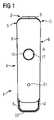
図面の図1および図2を最初に参照すると、電子たばこまたは「eシガレット」の形の個人用ヴェポライザ・デバイス1が、異なる位置で、部分断面図で示されている。該デバイス1は、細長い本体部分4の一方の端部領域3の所に取り付けられている交換可能なカートリッジ2を含む。細長い本体部分4は、デバイス1に電力を供給するバッテリ・ユニットDの形の電源ユニットを封入するケーシング5を含む。細長い本体4の該ケーシング5は、第1の位置A(すなわち図1に示されている)と第2の位置B(すなわち図2に示されている)との間で本体4の長手方向に移動可能なカバー部材6を含む。これに関連して、カバー部材6は、本体4の前面を覆って延在する前面パネル6’と、本体4の後面を覆って延在する後面カバーパネル6”とを含む。 Referring first to Figures 1 and 2 of the drawings, a
図面の図2に認められる通り、カートリッジ2は、気化される液体を貯蔵するリザーバ8を封入するハウジング7を含む。ハウジング7は、平坦な基部7’と、湾曲した上部肩領域7’”で移行してカートリッジ2の最上部のマウスピース9において生じるかまたは終端する略垂直に延在する側面7”とを有する。このようにして、ハウジング7の外殻構造は、リザーバ8を封入して、eシガレットのユーザによる吸引のために気化される液体(すなわち当該技術分野において既知の種類の)を貯蔵する小タンクを形成する。さらに、カートリッジ2は、基部7’から最上部までハウジング7の中央を通って延在し、ユーザによる吸引のために蒸気をマウスピース9へ案内するように構成されている空気流チャネルCを含む。空気流チャネルCは略円形の断面を有し、リザーバ8により取り囲まれている。蒸気を生成するために、カートリッジ2は、気化される液体を加熱して、吸引される蒸気を生成する、空気流チャネルCの内部には、コイル状に巻かれて設けられている発熱体またはワイヤを備えた電気ヒータを有するヴェポライザ・ユニットを組み込んでいる。ヴェポライザ・ユニット(図示せず)は、気化のために液体をリザーバ8から加熱ワイヤへ運ぶように構成されている液体送達手段をさらに含む。 As can be seen in Figure 2 of the drawings, the
図面の図1および図2を参照すると、前面パネル部材6’と後面パネル部材6”とで構成されているカバー部材6は、図1に示されている第1の位置Aと図2に示されている第2の位置Bとの間で、例えば摺動によりまたは並進で、デバイス本体4の長手方向に移動可能である。第1の延出状態位置Aでは、リザーバ8とヴェポライザ・ユニット10とを含む交換可能なカートリッジ2は、カバー部材6により、実質的に覆われているかまたは遮られている。このようにして、第1の位置Aでは、カバー部材6は、カートリッジ2を保護する物理的障壁を実現する。これにも関わらず、カバー部材6が第1の位置Aにある時であっても、カートリッジ2のリザーバ8内の液体の体積または量は視認することができる。すなわち、この位置では、カートリッジ2はカバー部材6により大部分覆われているかまたは遮られているが、カバー部材6に窓が設けられていてもよくかつ/またはカートリッジ2の側面領域Sがカバー部材6により覆われていないままとして、どのくらいの量の液体がリザーバ8内に残存しているかをユーザが視覚的に判断するための窓Wを含んでいてもよい。 1 and 2 of the drawings, the
第1の位置Aと第2の位置Bとの間で、ケーシング5の残部に対してカバー部材6を摺動させるかまたは移動させるために、前面パネル部材6’および後面パネル部材6”の少なくとも一方または両方が、ユーザの親指と指との間で保持され係合されていてもよい。第2の位置Bでは、カバー部材6は、カートリッジ2を部分的にもしくは実質的に覆われていないかまたは遮られていないままにするように後退する。すなわち、第2の位置Bでは、カバー部材6は、長手方向に、eシガレットもしくはヴェポライザ・デバイス1の使用状態位置または作動状態位置まで、カートリッジ2から後退する。この目的のために、本体4は、カバー部材6の開口部18の内部に設置されている丸いボタンの形で設けられているスイッチ17を含む。スイッチまたはボタン17はデバイス1を作動させるように構成されており、スイッチ17は、カバー部材6の下で、コントローラまたは制御ユニットの一部と動作的に接続している。これに関連して、デバイス1は、前面パネル6’および後面パネル6”が第1の位置Aから第2の位置Bへ移動した場合のみに、スイッチ17により作動され得るように設計されてもよい。スイッチ17は、デバイス1の動作状態を指示するために前面パネル6’上で照明するリング形インジケータ19により取り囲まれている。ヴェポライザ・デバイス1のこれらの要素はより詳細に後述される。 In order to slide or move the
さらに、カバー部材6の第2の位置Bは、個人用ヴェポライザ・デバイスまたはeシガレット1の本体部分4からカートリッジ2を取り外すために、かつ/または本体部分4にカートリッジ2を接続するために設計されている。上記の通り、カートリッジ2は、本体部分4の端部領域3に接続されるように構成されている。したがって、細長い本体4の端部領域3は、カートリッジ2の内部のヴェポライザ・ユニットのヒータに電力を接続するためにカートリッジ2に設けられている1つまたは複数の相補的電気コネクタと電気的に接続するための1つまたは複数の電気接点14を含むことが好ましい。 Further, the second position B of the
図3は、前述されているものと同様の実施形態によるカートリッジ2の斜視図を示す。前述されている通り、このカートリッジ2は、通常、気化される液体を貯蔵しかつハウジング7の中央を通ってカートリッジ2の最上部のマウスピース9まで延在する空気流チャネルCを画定するリザーバ8を封入するハウジング7を含む。さらに、カートリッジ2は、気化される液体を加熱して、吸入される蒸気を生成する、空気流チャネルCの内部にコイル状に巻かれて設けられている発熱体を備えた電気ヒータを有するヴェポライザ・ユニット(図示せず)を含む。ヴェポライザ・ユニットは、毛管現象または他の既知の機構によりリザーバ8から液体を運ぶように構成されている液体送達手段を含む。 Figure 3 shows a perspective view of a
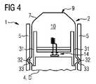
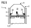
ここで図面の図4から図6までを参照すると、個人用ヴェポライザ・デバイス1の本体4の端部領域3を介した、カートリッジ2と電源(例えば、バッテリ・ユニットD)との間の3つの異なるタイプの機械的接続および電気的接続が概略的に示されている。各々の場合に、カートリッジ2は、デバイスのケーシング5の開いた上端部領域3内へのプッシュオン/プルオフ式接続のために構成されている。図4では、カートリッジ・ハウジング7の側面7”は、ケーシング5の内面上に形成されている相補的陥凹部33内での受け入れまたは係合のための突起部32を有する弾性部材または可撓性部材31(例えば、板ばねもしくは片持ち梁として形成されている)を含む。電気接点要素14が、カートリッジ2の下に設けられている電気接点を介したコントローラ13およびヒータへの電力供給のために、別個に設けられている。図5の実施形態では、カートリッジ・ハウジング7の側面7”は、ケーシング5の開いた上端部領域3に受け入れられ、弾性電気接点要素14が電源から上方に延在しており、カートリッジ・ハウジング7の側面7”に設けられている電気接点34に係合する。図6の実施形態では、対照的に、端部領域3において、個人用ヴェポライザ・デバイス1のカートリッジ2および本体部4の両方に設けられている磁気コネクタ要素35により、機械的接続が達成されている。カートリッジ・ハウジング7の基部7’の下方で、電気接点14により、電気的接続が再度別個に起こる。 4 to 6 of the drawings, three vaporizers between the
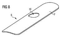
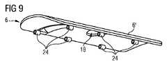
ここで図面の図7から図9までを参照すると、カバー部材6の幾何学的形状および構造がより明瞭に認められる。詳細には、カバー部材の前面パネル6’は、これの凸外形、これの厚さおよび可撓性により機能的にされている。詳細には、パネル6’は、第1の位置Aと第2の位置Bとの間で移動するように構成されているのみならず、撓むこともでき、デバイス1の動作に関するユーザインターフェースを形成することもできる。これに関連して、既に上記の通り、カバー部材6の前面パネル6’は、カバー部材6の開口部18の内部に設置されて、デバイス1の動作状態を指示するために前面パネル6’を照明するリング形インジケータ19により取り囲まれている、ボタンの形のスイッチ17などのユーザインターフェース要素を含む。スイッチまたはボタン17は、カバー部材6が第2の位置もしくは「使用中」状態位置Bへ移動させられた後、蒸気生成のためにデバイス1を作動させるように構成されている。また、前面パネル6’は、動作モードを設定するなど、さらなる機能を作動させるために、(例えば、個別にまたは明確に)この表面上に配置される1つまたは複数のさらなるスイッチまたはボタン21を含んでいてもよい。ボタン17、21の各々は、カバー部材6の下で、デバイス1のコントローラまたは制御ユニット13の一部と動作的に接続しており、これについては後述する。カバー部材6が第2の位置Bへ移動されると、インジケータ17は、デバイス1が作動しかつ/または動作の準備ができていることを通知するために照明してもよい。さらに、インジケータ20は、異なる色でかつ/または異なる方法(例えば、明滅または脈動)で照明して、ユーザに、バッテリ・ユニットD内の利用可能な電源が少ない(例えば、バッテリ・ユニットDを再充電すべきである)という信号を送ってもよい。この目的のために、eシガレット1の本体4の反対側端部領域22は、通常、再充電ドックもしくは再充電ステーションへの接続のためのかつ/または再充電ケーブルの接続のためのコネクタ23を含む。 7 to 9 of the drawings, the geometry and construction of
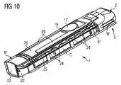
図面の図9から明らかであるように、前面パネル6’の裏面は、第1の位置Aと第2の位置Bとの間での長手方向移動中、本体部分4上の平行なレール部材25(図10に示されている)との滑り係合するためのスリーブ要素24を含む。このようにして、レール部材25は、カバー部材6の長手方向移動を案内するガイド手段としての機能を果たし、スリーブ要素24は、レールにより画定されている経路を辿る従動要素を形成する。さらに、図面の図10を参照すると、デバイス1の細長い本体部分4は、eシガレットのコントローラまたは制御ユニット13の一部を成す、前面パネル6’の下に取り付けられている回路基板(図示せず)を含む。 As is apparent from Figure 9 of the drawings, the rear surface of the front panel 6' is supported by
最後に、図面の図11を参照すると、図1から図10に関して前述されている、本発明の実施形態による個人用ヴェポライザ・デバイス1、特に電子喫煙具の中にカートリッジを設置する方法のステップを概略的に示す流れ図が示されている。これに関連して、図11の第1の枠iは、取外し可能な、気化される液体を貯蔵するリザーバ8を含むカートリッジ2が接続されるように構成されている細長い本体部分4を有する個人用ヴェポライザ・デバイス1を設けるステップを示す。第2の枠iiは、第1の延出状態位置Aと第2の後退状態位置Bとの間で本体部分4の長手方向に移動可能なカバー部材6を細長い本体部分4上に設けるステップを示す。第3の枠iiiは、カバー部材6を第2の後退状態位置Bへ移動させて、本体部分4の端部領域3にアクセスするステップを示す。図面の図11の最後の枠ivは、カートリッジ2を、個人用ヴェポライザ・デバイス1の本体部分4のアクセスされた端部領域3に取り付けるステップを示す。 Finally, referring to Figure 11 of the drawings, the method steps for installing a cartridge in a
本発明の特定の実施形態が本明細書に図示され、記載されているが、当業者には、様々な代替的なかつ/または等価の実施が存在することが認識されよう。例示的実施形態(単数または複数)が例に過ぎず、範囲、適用性または構造を限定することが全く意図されていないことが認識されるべきである。むしろ、上述の要約および詳細な説明は、当業者に、少なくとも1つの例示的実施形態を実施するための重宝な手引きをもたらし、添付の特許請求の範囲およびこれらの法的均等物に記載されている範囲から逸脱することなく、例示的実施形態に記載されている要素の機能および配置に様々な変更が施されてもよいことが理解される。全般的に、本願は、本明細書において検討されている特定の実施形態のいかなる適応形態または変形形態も包含することが意図されている。 While specific embodiments of the invention have been illustrated and described herein, those skilled in the art will recognize that various alternative and/or equivalent implementations exist. It should be appreciated that the exemplary embodiment(s) are examples only and are in no way intended to limit scope, applicability, or structure. Rather, the foregoing summary and detailed description will provide those skilled in the art with useful guidance for implementing at least one exemplary embodiment, as defined in the appended claims and their legal equivalents. It is understood that various changes may be made in the function and arrangement of elements described in the illustrative embodiments without departing from the scope. Generally, this application is intended to cover any adaptations or variations of the specific embodiments discussed herein.
また、本文献において、用語「comprise(含む)」、「comprising(含む)」、「include(含む)」、「including(含む)」、「contain(含有する)」、「containing(含有する)」、「have(有する)」、「having(有する)」およびこれらの任意の変形は、本明細書に記載されている工程、方法、デバイス、装置またはシステムが、記載されている特徴または部分または要素またはステップに限定されず、明示的に列挙されていないかまたはこのような工程、方法、物品もしくは装置に固有の他の要素、特徴、部分あるいはステップを含み得るように、包括的な(すなわち非排他的な)意味で理解されることが意図されていることが認識されよう。さらに、本明細書において用いられている用語「a」および「an」は、特に明記されていない限り、「1つまたは複数の」の意味で理解されることが意図されている。さらに、用語「第1の」、「第2の」、「第3の」等は単に標示として用いられているに過ぎず、数的要件を課すことまたはこれらの対象の重要性の一定の序列を確立することは意図されていない。 Also, in this document, the terms “comprise”, “comprising”, “include”, “including”, “contain”, “containing” , "have," "have," and any variations thereof, are used to describe the processes, methods, devices, apparatus, or systems described herein that are used to or is not limited to steps, but is generic (i.e., non- are intended to be understood in an exclusive) sense. Additionally, as used herein, the terms "a" and "an" are intended to be understood in the sense of "one or more," unless otherwise specified. Furthermore, the terms "first", "second", "third", etc. are used merely as indicators and do not impose numerical requirements or a certain hierarchy of importance of these objects. is not intended to establish
1 個人用ヴェポライザ・デバイスまたはeシガレット
2 カートリッジ
3 細長い本体の端部領域
4 細長い本体
5 ケーシング
6 カバー部材
6’ 前面パネル
6” 後面パネル
7 ハウジング
7’ ハウジングの基部
7” ハウジングの側面
7’” ハウジングの肩領域
8 リザーバ
9 マウスピース
10 ヴェポライザ・ユニット
14 電気接点
15 導体要素
17 スイッチまたはボタン
18 カバー部材の開口部
19 リング形インジケータ
21 モードのスイッチまたはボタン
22 本体部分の反対側端部領域
23 充電コネクタ
24 スリーブ要素
25 レール部材
26 回路基板
29 導光要素
31 弾性部材または可撓性部材
32 突起部
33 陥凹部
34 電気接点
35 磁気コネクタ要素
A カバー部材の第1の位置
B カバー部材の第2の位置
D バッテリ・ユニット
C 空気流チャネル
S ケーシングの側面
W 窓1 personal vaporizer device or
Claims (14)
Translated fromJapanese該カートリッジ(2)が接続され、第1の位置(A)と第2の位置(B)との間でその長手方向に移動可能なカバー部材(6)を含む、細長い本体部分(4)と、を含み、
前記カートリッジ(2)は、前記第1の位置(A)において、前記カバー部材(6)により、少なくとも部分的に覆われるかまたは遮られる、特に電子喫煙具である、個人用ヴェポライザ・デバイス(1)。a cartridge (2) containing a reservoir (8) for storing the liquid to be vaporized;
an elongated body portion (4) including a cover member (6) to which the cartridge (2) is connected and which is longitudinally movable between a first position (A) and a second position (B); , including
A personal vaporizer device (1), in particular an electronic smoking article, wherein said cartridge (2) is at least partially covered or blocked by said cover member (6) in said first position (A). ).
イス(1)。Personal vaporizer device according to claim 1, wherein the amount of liquid in the reservoir (8) of the cartridge (2) is visible when the cover member (6) is in the first position (A). (1).
前記カバー部材(6)は、前記細長い本体部分(4)の前面を覆って延在する前面カバーパネル(6’)および前記細長い本体部分(4)の後面を覆って延在する後面カバーパネル(6”)のうちの少なくとも1つを含む、請求項5に記載の個人用ヴェポライザ・デバイス(1)。said cartridge (2) is adapted to be connected to an end region (3) of said elongated body portion (4),
The cover member (6) comprises a front cover panel (6') extending over the front surface of the elongate body portion (4) and a rear cover panel (6') extending over the rear surface of the elongate body portion (4). 6'').
前記カートリッジ(2)が接続されるように構成され、第1の位置(A)と第2の位置(B)との間でその長手方向に移動可能なカバー部材(6)を含む、細長い本体部分(4)を含み、
前記カバー部材(6)は、前記第1の位置(A)において、前記カートリッジ(2)を少なくとも部分的に覆うかまたは遮るように構成され、配置されている、個人用ヴェポライザ・デバイス(1)。A personal vaporizer device (1), in particular an electronic smoking article, configured to receive a removable cartridge (2) containing a reservoir (8) for storing liquid to be vaporized, comprising:
an elongate body comprising a cover member (6) configured to be connected to said cartridge (2) and movable longitudinally thereof between a first position (A) and a second position (B); comprising part (4),
A personal vaporizer device (1), wherein said cover member (6) is constructed and arranged to at least partially cover or block said cartridge (2) in said first position (A). .
前記細長い本体部分(4)の前記端部領域(3)は、前記カートリッジ(2)に設けられた相補的電気コネクタと電気的に接続するための電気コネクタ(14)を含む、請求項9に記載の個人用ヴェポライザ・デバイス(1)。said cartridge (2) is configured to be connected to an end region (3) of said elongated body portion (4);
10. According to claim 9, wherein said end region (3) of said elongated body portion (4) comprises an electrical connector (14) for electrically connecting with a complementary electrical connector provided on said cartridge (2). A personal vaporizer device (1) as described.
前記デバイス(1)の前記1つまたは複数の機能は、前記カバー部材(6)が前記第2の位置(B)にある時に作動する、請求項1から11のいずれか一項に記載の個人用ヴェポライザ・デバイス(1)。Said elongated body portion (4) comprises a switch for activating one or more functions of said device (1), which switch is provided on or on said cover member (6). ) and preferably operatively connected to
12. The individual according to any one of the preceding claims, wherein said one or more functions of said device (1) are activated when said cover member (6) is in said second position (B). vaporizer device (1) for
取外し可能な、気化される液体を貯蔵するリザーバ(8)を含むカートリッジ(2)が接続されるように構成されている細長い本体部分(4)を有する個人用ヴェポライザ・デバイス(1)を用意するステップと、
第1の延出状態位置(A)と第2の後退状態位置(B)との間で前記本体部分(4)の長手方向に移動可能なカバー部材(6)を前記細長い本体部分(4)上に設けるステップと、
カバー部材(6)を前記第2の位置(B)へ移動させて、前記本体部分(4)の端部領域(3)にアクセスするステップと、
前記取外し可能なカートリッジ(2)を個人用ヴェポライザ・デバイス(1)の前記本体部分(4)の前記アクセスされた端部領域(3)に取り付けるステップと、を含む、方法。A method of installing a cartridge (2) in a personal vaporizer device (1), particularly an electronic smoking article, comprising:
Providing a personal vaporizer device (1) having an elongated body portion (4) configured to be connected to a removable cartridge (2) containing a reservoir (8) for storing a liquid to be vaporized. a step;
A cover member (6) movable longitudinally of said body portion (4) between a first extended position (A) and a second retracted position (B) on said elongated body portion (4). a step provided above;
moving a cover member (6) to said second position (B) to access an end region (3) of said body portion (4);
attaching said removable cartridge (2) to said accessed end region (3) of said body portion (4) of a personal vaporizer device (1).
Applications Claiming Priority (4)
| Application Number | Priority Date | Filing Date | Title |
|---|---|---|---|
| EP15201281 | 2015-12-18 | ||
| EP15201281.1 | 2015-12-18 | ||
| JP2018532155AJP6857658B2 (en) | 2015-12-18 | 2016-12-15 | Personal vaporizer device |
| JP2021042687AJP7122425B2 (en) | 2015-12-18 | 2021-03-16 | Personal vaporizer devices and cartridges |
Related Parent Applications (1)
| Application Number | Title | Priority Date | Filing Date |
|---|---|---|---|
| JP2021042687ADivisionJP7122425B2 (en) | 2015-12-18 | 2021-03-16 | Personal vaporizer devices and cartridges |
Publications (1)
| Publication Number | Publication Date |
|---|---|
| JP2022163142Atrue JP2022163142A (en) | 2022-10-25 |
Family
ID=54979479
Family Applications (3)
| Application Number | Title | Priority Date | Filing Date |
|---|---|---|---|
| JP2018532155AExpired - Fee RelatedJP6857658B2 (en) | 2015-12-18 | 2016-12-15 | Personal vaporizer device |
| JP2021042687AActiveJP7122425B2 (en) | 2015-12-18 | 2021-03-16 | Personal vaporizer devices and cartridges |
| JP2022126535APendingJP2022163142A (en) | 2015-12-18 | 2022-08-08 | personal vaporizer device |
Family Applications Before (2)
| Application Number | Title | Priority Date | Filing Date |
|---|---|---|---|
| JP2018532155AExpired - Fee RelatedJP6857658B2 (en) | 2015-12-18 | 2016-12-15 | Personal vaporizer device |
| JP2021042687AActiveJP7122425B2 (en) | 2015-12-18 | 2021-03-16 | Personal vaporizer devices and cartridges |
Country Status (20)
| Country | Link |
|---|---|
| US (2) | US20180360125A1 (en) |
| EP (3) | EP3386323B1 (en) |
| JP (3) | JP6857658B2 (en) |
| KR (1) | KR102738815B1 (en) |
| CN (3) | CN115474718A (en) |
| CA (1) | CA3008383A1 (en) |
| CY (1) | CY1124235T1 (en) |
| DK (1) | DK3386323T3 (en) |
| EA (2) | EA202092986A3 (en) |
| ES (2) | ES2863570T3 (en) |
| HR (1) | HRP20210404T1 (en) |
| HU (1) | HUE053803T2 (en) |
| LT (1) | LT3386323T (en) |
| PL (2) | PL3386323T3 (en) |
| PT (1) | PT3386323T (en) |
| RS (1) | RS61567B1 (en) |
| SI (1) | SI3386323T1 (en) |
| TW (1) | TWI631908B (en) |
| WO (1) | WO2017102969A1 (en) |
| ZA (1) | ZA201804154B (en) |
Cited By (1)
| Publication number | Priority date | Publication date | Assignee | Title |
|---|---|---|---|---|
| WO2024080211A1 (en) | 2022-10-11 | 2024-04-18 | 株式会社日本製鋼所 | Injection molding machine hopper, injection device, and injection molding machine |
Families Citing this family (66)
| Publication number | Priority date | Publication date | Assignee | Title |
|---|---|---|---|---|
| US20160345631A1 (en) | 2005-07-19 | 2016-12-01 | James Monsees | Portable devices for generating an inhalable vapor |
| US10279934B2 (en) | 2013-03-15 | 2019-05-07 | Juul Labs, Inc. | Fillable vaporizer cartridge and method of filling |
| US20160366947A1 (en) | 2013-12-23 | 2016-12-22 | James Monsees | Vaporizer apparatus |
| USD842536S1 (en) | 2016-07-28 | 2019-03-05 | Juul Labs, Inc. | Vaporizer cartridge |
| USD825102S1 (en) | 2016-07-28 | 2018-08-07 | Juul Labs, Inc. | Vaporizer device with cartridge |
| US10076139B2 (en) | 2013-12-23 | 2018-09-18 | Juul Labs, Inc. | Vaporizer apparatus |
| US10058129B2 (en) | 2013-12-23 | 2018-08-28 | Juul Labs, Inc. | Vaporization device systems and methods |
| DE202014011260U1 (en) | 2013-12-23 | 2018-11-13 | Juul Labs Uk Holdco Limited | Systems for an evaporation device |
| US10159282B2 (en) | 2013-12-23 | 2018-12-25 | Juul Labs, Inc. | Cartridge for use with a vaporizer device |
| MX394125B (en) | 2014-12-05 | 2025-03-24 | Juul Labs Inc | CALIBRATED DOSE CONTROL |
| EP3386323B1 (en) | 2015-12-18 | 2021-02-03 | JT International S.A. | Personal vaporizer device |
| EP3413960B1 (en) | 2016-02-11 | 2021-03-31 | Juul Labs, Inc. | Fillable vaporizer cartridge and method of filling |
| CO2018009342A2 (en) | 2016-02-11 | 2018-09-20 | Juul Labs Inc | Secure fixing cartridges for vaporizing devices |
| US10405582B2 (en) | 2016-03-10 | 2019-09-10 | Pax Labs, Inc. | Vaporization device with lip sensing |
| USD849996S1 (en) | 2016-06-16 | 2019-05-28 | Pax Labs, Inc. | Vaporizer cartridge |
| USD836541S1 (en) | 2016-06-23 | 2018-12-25 | Pax Labs, Inc. | Charging device |
| USD851830S1 (en) | 2016-06-23 | 2019-06-18 | Pax Labs, Inc. | Combined vaporizer tamp and pick tool |
| USD885656S1 (en)* | 2016-12-01 | 2020-05-26 | Jt International S.A. | Electronic cigarette |
| JP2020500664A (en) | 2016-12-12 | 2020-01-16 | ブイエムアール・プロダクツ・リミテッド・ライアビリティ・カンパニーVmr Products Llc | Vaporizer |
| USD887632S1 (en) | 2017-09-14 | 2020-06-16 | Pax Labs, Inc. | Vaporizer cartridge |
| CN111050582B (en) | 2017-10-03 | 2023-11-24 | 菲利普莫里斯生产公司 | Heater for aerosol-generating device with connector |
| US11184954B2 (en)* | 2017-10-03 | 2021-11-23 | Altria Client Services Llc | Heater for aerosol-generating device with connectors |
| GB201718570D0 (en)* | 2017-11-09 | 2017-12-27 | Eweidah Fadi | Compact sized vaping device |
| KR200493437Y1 (en)* | 2017-12-25 | 2021-03-29 | 상하이 뉴 토바코 프로덕트 리서치 인스티튜트 컴퍼니 리미티드 | Aerosol-generating device and electronic cigarette |
| USD865278S1 (en)* | 2018-02-05 | 2019-10-29 | Shenzhen Transpring Enterprise Ltd. | Vape part |
| EP3560362A1 (en)* | 2018-04-24 | 2019-10-30 | JT International SA | Electronic cigarette with protective cover |
| WO2019206943A1 (en) | 2018-04-24 | 2019-10-31 | Jt International Sa | Electronic cigarette with protective cover |
| US10888125B2 (en) | 2018-06-27 | 2021-01-12 | Juul Labs, Inc. | Vaporizer device with subassemblies |
| TW202011845A (en)* | 2018-07-24 | 2020-04-01 | 瑞士商傑太日煙國際股份有限公司 | Side-by-side terminal for personal vaporizing device |
| AU2019420129B2 (en) | 2018-08-10 | 2024-08-22 | Furna Inc. | Vaporizer apparatuses having a movable head and related methods |
| USD951535S1 (en)* | 2018-09-26 | 2022-05-10 | Philip Morris Products S.A. | Aerosol generating device |
| AR116722A1 (en)* | 2018-10-08 | 2021-06-09 | Juul Labs Inc | ASSEMBLY OF CHARGE ADAPTER OF A VAPORIZER |
| US12232526B2 (en) | 2018-10-12 | 2025-02-25 | Rai Strategic Holdings, Inc. | Connectors for forming electrical and mechanical connections between interchangeable units in an aerosol delivery system |
| US11678700B2 (en) | 2018-10-12 | 2023-06-20 | Rai Strategic Holdings, Inc. | Aerosol delivery device with visible indicator |
| US10939702B2 (en) | 2018-10-12 | 2021-03-09 | Rai Strategic Holdings, Inc. | Connectors for forming electrical and mechanical connections between interchangeable units in an aerosol delivery system |
| US10791767B2 (en)* | 2018-10-12 | 2020-10-06 | Rai Strategic Holdings, Inc. | Connectors for forming electrical and mechanical connections between interchangeable units in an aerosol delivery system |
| US11974603B2 (en) | 2018-10-12 | 2024-05-07 | Rai Strategic Holdings, Inc. | Aerosol delivery device with visible indicator |
| EP3876761A1 (en) | 2018-11-05 | 2021-09-15 | Juul Labs, Inc. | Cartridges for vaporizer devices |
| USD928400S1 (en)* | 2018-11-05 | 2021-08-17 | Philip Morris Products S.A. | Device for generating nicotine containing aerosol for inhalation |
| JP1652040S (en)* | 2019-01-29 | 2020-02-03 | Electronic Cigarette | |
| KR102253048B1 (en)* | 2019-04-25 | 2021-05-17 | 주식회사 케이티앤지 | Recharging system for aerosol generating apparatus |
| JP7569332B2 (en)* | 2019-05-16 | 2024-10-17 | フィリップ・モーリス・プロダクツ・ソシエテ・アノニム | DEVICE ASSEMBLY METHOD AND DEVICES MADE ACCORDING TO SUCH METHOD - Patent application |
| CN110179164B (en)* | 2019-06-12 | 2024-05-24 | 陈玉水 | Electronic cigarette component |
| CN112205673B (en)* | 2019-07-12 | 2025-06-13 | 深圳市卓力能技术有限公司 | An aerosol generating device |
| CN112273721B (en)* | 2019-07-12 | 2025-06-13 | 深圳市卓力能技术有限公司 | An aerosol generating device |
| US12185762B2 (en)* | 2019-08-30 | 2025-01-07 | Jt International S.A. | Mouthpiece portion for an electronic cigarette preventing any undesired loss of liquid |
| EP4021220B1 (en)* | 2019-08-30 | 2025-04-09 | JT International SA | Mouthpiece portion for an electronic cigarette |
| KR102390421B1 (en)* | 2019-10-11 | 2022-04-25 | 주식회사 케이티앤지 | Aerosol generating device and method for showing the remaining amount of liquid composition using light source |
| US11490656B2 (en) | 2019-11-26 | 2022-11-08 | Altria Client Services Llc | Nicotine pod assemblies and nicotine e-vaping devices |
| US11484062B2 (en) | 2019-11-26 | 2022-11-01 | Altria Client Services Llc | Nicotine pod assemblies and nicotine e-vaping devices |
| US11564416B2 (en) | 2019-11-26 | 2023-01-31 | Altria Client Services Llc | Non-nicotine pod assemblies and non-nicotine e-vaping devices |
| US11528939B2 (en) | 2019-11-26 | 2022-12-20 | Altria Client Services Llc | Non-nicotine pod assemblies and non-nicotine e-vaping devices |
| US11596172B2 (en) | 2019-11-26 | 2023-03-07 | Altria Client Services Llc | Non-nicotine pod assemblies and non-nicotine e-vaping devices |
| US11528938B2 (en) | 2019-11-26 | 2022-12-20 | Altria Client Services Llc | Non-nicotine pod assemblies and non-nicotine e-vaping devices |
| US11528937B2 (en) | 2019-11-26 | 2022-12-20 | Altria Client Services Llc | Nicotine pod assemblies and nicotine e-vaping devices |
| US11576432B2 (en) | 2019-11-26 | 2023-02-14 | Altria Client Services Llc | Nicotine pod assemblies and nicotine e-vaping devices |
| WO2021119821A1 (en)* | 2019-12-20 | 2021-06-24 | Furna Inc. | Vaporizer apparatus having reversible head and related methods |
| CN111067148A (en)* | 2020-03-03 | 2020-04-28 | 泰州亚泽塑胶有限公司 | Electron cigarette holder propelling movement assembly |
| WO2021185530A1 (en)* | 2020-03-18 | 2021-09-23 | Jt International S.A. | Aerosol generation device with a movable panel for hiding interfaces |
| US11856986B2 (en)* | 2020-10-19 | 2024-01-02 | Rai Strategic Holdings, Inc. | Customizable panel for aerosol delivery device |
| US20230404168A1 (en)* | 2020-11-06 | 2023-12-21 | Jt International S.A. | Aerosol Generation Device |
| WO2022230086A1 (en)* | 2021-04-28 | 2022-11-03 | 日本たばこ産業株式会社 | Flavor inhaler, and method for manufacturing flavor inhaler |
| KR102715289B1 (en)* | 2021-05-28 | 2024-10-11 | 신종수 | Electronic Cigarette |
| US12127587B2 (en)* | 2021-11-16 | 2024-10-29 | Ivision Tech Inc. | Dual vaporizer |
| US20240164454A1 (en)* | 2022-11-18 | 2024-05-23 | Pangea Proper LLC | Vapor inhalation device including a pivot for rotating |
| WO2024188728A1 (en)* | 2023-03-10 | 2024-09-19 | Nicoventures Trading Limited | User interface for an aerosol provision device |
Citations (6)
| Publication number | Priority date | Publication date | Assignee | Title |
|---|---|---|---|---|
| CN204157645U (en)* | 2014-04-14 | 2015-02-18 | 惠州市吉瑞科技有限公司 | Electronic cigarette |
| US20150059779A1 (en)* | 2010-04-30 | 2015-03-05 | Loec, Inc. | Dosing control for an electronic smoking device |
| WO2015082560A1 (en)* | 2013-12-03 | 2015-06-11 | Philip Morris Products S.A. | Aerosol-generating article and electrically operated system incorporating a taggant |
| WO2015117704A1 (en)* | 2014-02-10 | 2015-08-13 | Philip Morris Products S.A. | An aerosol-generating system having a heater assembly and a cartridge for an aerosol-generating system having a fluid permeable heater assembly |
| US20150258289A1 (en)* | 2014-03-12 | 2015-09-17 | R.J. Reynolds Tobacco Company | Aerosol Delivery System and Related Method, Apparatus, and Computer Program Product for Providing Control Information to an Aerosol Delivery Device Via a Cartridge |
| WO2015165812A1 (en)* | 2014-04-30 | 2015-11-05 | Philip Morris Products S.A. | A container having a heater for an aerosol-generating device, and aerosol-generating device |
Family Cites Families (58)
| Publication number | Priority date | Publication date | Assignee | Title |
|---|---|---|---|---|
| GB531704A (en) | 1939-07-29 | 1941-01-09 | John Cartner | Improvements in and relating to containers for inhalants |
| CN1131676C (en)* | 1994-02-25 | 2003-12-24 | 菲利普莫里斯生产公司 | Electric smoking system and cigarette for delivering cigarette aroma |
| US6606992B1 (en)* | 1999-06-30 | 2003-08-19 | Nektar Therapeutics | Systems and methods for aerosolizing pharmaceutical formulations |
| UA80123C2 (en) | 2002-04-09 | 2007-08-27 | Boehringer Ingelheim Pharma | Inhalation kit comprising inhalable powder of tiotropium |
| US7726320B2 (en) | 2006-10-18 | 2010-06-01 | R. J. Reynolds Tobacco Company | Tobacco-containing smoking article |
| EP2044967A1 (en) | 2007-10-01 | 2009-04-08 | Boehringer Ingelheim Pharma GmbH & Co. KG | Atomiser |
| AT507187B1 (en) | 2008-10-23 | 2010-03-15 | Helmut Dr Buchberger | INHALER |
| US8851068B2 (en)* | 2009-04-21 | 2014-10-07 | Aj Marketing Llc | Personal inhalation devices |
| KR200465795Y1 (en)* | 2011-01-07 | 2013-03-11 | 이영인 | Electronic smoking device |
| WO2014198157A1 (en) | 2013-06-13 | 2014-12-18 | Shenzhen Kanger Technology Co., Ltd. | Ceramic heating elements for electronic cigarettes |
| KR20120008751U (en) | 2011-06-13 | 2012-12-24 | 이영찬 | an electronic cigarette |
| US8528569B1 (en)* | 2011-06-28 | 2013-09-10 | Kyle D. Newton | Electronic cigarette with liquid reservoir |
| KR200460784Y1 (en)* | 2011-10-17 | 2012-06-11 | 주식회사 시그닛코리아 | Electronic cigarette |
| CN202385728U (en) | 2011-11-25 | 2012-08-22 | 周学武 | Electronic cigarette with built-in atomizer |
| BR112014016425B1 (en) | 2012-01-03 | 2020-12-15 | Philip Morris Products S.A | AEROSOL GENERATION SYSTEM |
| WO2013174001A1 (en) | 2012-05-24 | 2013-11-28 | 深圳葆威道科技有限公司 | Constant-temperature atomizer with no tar leakage and liquid cigarette tar repeatedly added |
| CN202635604U (en) | 2012-06-18 | 2013-01-02 | 刘团芳 | Oval electronic cigarette |
| US9271527B2 (en) | 2012-06-20 | 2016-03-01 | Huizhou Kimree Technology Co., Ltd., Shenzhen Branch | Electronic cigarette and electronic cigarette device |
| US9427023B2 (en) | 2012-06-20 | 2016-08-30 | Huizhou Kimree Technology Co., Ltd., Shenzhen Branch | Electronic cigarette and electronic cigarette device |
| KR101802616B1 (en) | 2012-07-09 | 2017-11-28 | 킴르 하이테크 인코퍼레이티드 | Electronic cigarette |
| WO2014085999A1 (en)* | 2012-12-05 | 2014-06-12 | Liu Qiuming | Magnetic connection electronic cigarette with connector |
| US9993023B2 (en)* | 2013-02-22 | 2018-06-12 | Altria Client Services Llc | Electronic smoking article |
| TWI568370B (en)* | 2013-03-26 | 2017-02-01 | 富特姆控股第一有限公司 | Electronic cigarette and method of vaporizing a liquid in an electronic cigarette |
| CN105473012B (en)* | 2013-06-14 | 2020-06-19 | 尤尔实验室有限公司 | Multiple heating elements with separate vaporizable materials in electronic vaporization equipment |
| US20140373857A1 (en)* | 2013-06-20 | 2014-12-25 | Dan Steinberg | Herbal Vaporizing Device |
| GB2515562B (en)* | 2013-06-28 | 2016-04-06 | Totally Wicked Ltd | Vaporiser unit and fluid reservoir for an atomiser |
| CN203388269U (en) | 2013-07-25 | 2014-01-15 | 刘秋明 | Electronic cigarette |
| EP2835063B1 (en)* | 2013-08-06 | 2019-04-10 | Fontem Holdings 1 B.V. | Electronic smoking device and process of manufacturing thereof |
| CN203466247U (en)* | 2013-08-27 | 2014-03-05 | 深圳市合元科技有限公司 | Electronic cigarette power supply device and electronic cigarette |
| WO2015027470A1 (en) | 2013-08-30 | 2015-03-05 | Liu Shuigen | Atomizer and electronic cigarette comprised of atomizer |
| US10039321B2 (en)* | 2013-11-12 | 2018-08-07 | Vmr Products Llc | Vaporizer |
| US20150216237A1 (en) | 2014-01-22 | 2015-08-06 | E-Nicotine Technology, Inc. | Methods and devices for smoking urge relief |
| CN203789137U (en) | 2014-01-26 | 2014-08-27 | 深圳市合元科技有限公司 | Baking type smoke generating device and smoke sucking-in device |
| KR20230167768A (en)* | 2014-02-10 | 2023-12-11 | 필립모리스 프로덕츠 에스.에이. | Cartridge with a heater assembly for an aerosol-generating system |
| US11696604B2 (en)* | 2014-03-13 | 2023-07-11 | Rai Strategic Holdings, Inc. | Aerosol delivery device and related method and computer program product for controlling an aerosol delivery device based on input characteristics |
| CN103948174B (en) | 2014-03-27 | 2017-08-08 | 深圳麦克韦尔股份有限公司 | Electronic cigarette |
| EP2929903B1 (en) | 2014-04-08 | 2018-05-09 | Shenzhen First Union Technology Co., Ltd. | Atomizer and electronic cigarette |
| CN104114050B (en) | 2014-05-30 | 2019-01-18 | 深圳麦克韦尔股份有限公司 | Electronic cigarette and its atomizer |
| WO2016005530A1 (en)* | 2014-07-11 | 2016-01-14 | Philip Morris Products S.A. | Aerosol-forming cartridge comprising a liquid nicotine source |
| CN203986131U (en)* | 2014-07-31 | 2014-12-10 | 张银虎 | The electronic cigarette that a kind of atomizer is built-in |
| GB2529201A (en)* | 2014-08-13 | 2016-02-17 | Batmark Ltd | Device and method |
| CN204335831U (en) | 2014-08-14 | 2015-05-20 | 惠州市吉瑞科技有限公司 | A kind of atomizer and electronic cigarette |
| PL3750583T3 (en)* | 2014-10-14 | 2022-06-27 | Fontem Holdings 1 B.V. | Electronic smoking device and cartridge |
| BR112017010106A2 (en) | 2014-11-17 | 2018-01-02 | Mcneil Ab | disposable cartridge for use in an electronic nicotine release system |
| WO2016090037A1 (en)* | 2014-12-02 | 2016-06-09 | Goldstein Gabriel Marc | Vaporizing reservoir |
| CN104544570B (en) | 2014-12-31 | 2017-12-08 | 深圳麦克韦尔股份有限公司 | Inhalator and its atomizing component |
| CN104738816B (en)* | 2015-02-04 | 2024-08-02 | 深圳市合元科技有限公司 | Atomizer, electronic cigarette and liquid storage device suitable for replacement |
| CN204444258U (en) | 2015-02-13 | 2015-07-08 | 林光榕 | Electronic smoke atomizer |
| CA2977246C (en)* | 2015-02-25 | 2019-08-27 | Robert Schneider | Handheld apparatus for vaporization of plant-based or synthetic compounds by laser |
| US10064432B2 (en)* | 2015-04-22 | 2018-09-04 | Altria Client Services Llc | Pod assembly, dispensing body, and E-vapor apparatus including the same |
| CN204670386U (en) | 2015-04-29 | 2015-09-30 | 深圳市合元科技有限公司 | Atomizer and use the electronic cigarette of this atomizer |
| CN204682533U (en) | 2015-05-22 | 2015-10-07 | 深圳市腾烟科技有限公司 | A kind of electronic smoke atomizer with lock functional oil |
| EP3103355A1 (en) | 2015-06-08 | 2016-12-14 | Shenzhen Smaco Technology Limited | Electronic cigarette and an atomizing device thereof |
| GB201511349D0 (en)* | 2015-06-29 | 2015-08-12 | Nicoventures Holdings Ltd | Electronic aerosol provision systems |
| GB201511359D0 (en)* | 2015-06-29 | 2015-08-12 | Nicoventures Holdings Ltd | Electronic vapour provision system |
| KR20170006253A (en)* | 2015-07-07 | 2017-01-17 | 주식회사 케이티앤지 | Electronic cigarette |
| GB2542838B (en)* | 2015-10-01 | 2022-01-12 | Nicoventures Trading Ltd | Aerosol provision system |
| EP3386323B1 (en) | 2015-12-18 | 2021-02-03 | JT International S.A. | Personal vaporizer device |
- 2016
- 2016-12-15EPEP16809444.9Apatent/EP3386323B1/enactiveActive
- 2016-12-15ESES16809444Tpatent/ES2863570T3/enactiveActive
- 2016-12-15KRKR1020187019999Apatent/KR102738815B1/enactiveActive
- 2016-12-15EAEA202092986Apatent/EA202092986A3/enunknown
- 2016-12-15CNCN202211347496.0Apatent/CN115474718A/enactivePending
- 2016-12-15USUS16/061,973patent/US20180360125A1/ennot_activeAbandoned
- 2016-12-15PLPL16809444Tpatent/PL3386323T3/enunknown
- 2016-12-15EPEP21154281.6Apatent/EP3871519A1/ennot_activeWithdrawn
- 2016-12-15HRHRP20210404TTpatent/HRP20210404T1/enunknown
- 2016-12-15RSRS20210310Apatent/RS61567B1/enunknown
- 2016-12-15SISI201631125Tpatent/SI3386323T1/enunknown
- 2016-12-15CACA3008383Apatent/CA3008383A1/enactivePending
- 2016-12-15ESES20214564Tpatent/ES2952570T3/enactiveActive
- 2016-12-15LTLTEP16809444.9Tpatent/LT3386323T/enunknown
- 2016-12-15WOPCT/EP2016/081231patent/WO2017102969A1/ennot_activeCeased
- 2016-12-15CNCN201680073881.7Apatent/CN108601400A/enactivePending
- 2016-12-15PLPL20214564.5Tpatent/PL3821724T3/enunknown
- 2016-12-15HUHUE16809444Apatent/HUE053803T2/enunknown
- 2016-12-15CNCN202211347849.7Apatent/CN115474719A/enactivePending
- 2016-12-15JPJP2018532155Apatent/JP6857658B2/ennot_activeExpired - Fee Related
- 2016-12-15PTPT168094449Tpatent/PT3386323T/enunknown
- 2016-12-15EAEA201891382Apatent/EA037265B1/enunknown
- 2016-12-15DKDK16809444.9Tpatent/DK3386323T3/enactive
- 2016-12-15EPEP20214564.5Apatent/EP3821724B1/enactiveActive
- 2016-12-16TWTW105141954Apatent/TWI631908B/ennot_activeIP Right Cessation
- 2018
- 2018-06-21ZAZA2018/04154Apatent/ZA201804154B/enunknown
- 2021
- 2021-03-16JPJP2021042687Apatent/JP7122425B2/enactiveActive
- 2021-04-21CYCY20211100345Tpatent/CY1124235T1/enunknown
- 2022
- 2022-08-08JPJP2022126535Apatent/JP2022163142A/enactivePending
- 2022-11-21USUS17/991,434patent/US20230082657A1/enactivePending
Patent Citations (6)
| Publication number | Priority date | Publication date | Assignee | Title |
|---|---|---|---|---|
| US20150059779A1 (en)* | 2010-04-30 | 2015-03-05 | Loec, Inc. | Dosing control for an electronic smoking device |
| WO2015082560A1 (en)* | 2013-12-03 | 2015-06-11 | Philip Morris Products S.A. | Aerosol-generating article and electrically operated system incorporating a taggant |
| WO2015117704A1 (en)* | 2014-02-10 | 2015-08-13 | Philip Morris Products S.A. | An aerosol-generating system having a heater assembly and a cartridge for an aerosol-generating system having a fluid permeable heater assembly |
| US20150258289A1 (en)* | 2014-03-12 | 2015-09-17 | R.J. Reynolds Tobacco Company | Aerosol Delivery System and Related Method, Apparatus, and Computer Program Product for Providing Control Information to an Aerosol Delivery Device Via a Cartridge |
| CN204157645U (en)* | 2014-04-14 | 2015-02-18 | 惠州市吉瑞科技有限公司 | Electronic cigarette |
| WO2015165812A1 (en)* | 2014-04-30 | 2015-11-05 | Philip Morris Products S.A. | A container having a heater for an aerosol-generating device, and aerosol-generating device |
Cited By (1)
| Publication number | Priority date | Publication date | Assignee | Title |
|---|---|---|---|---|
| WO2024080211A1 (en) | 2022-10-11 | 2024-04-18 | 株式会社日本製鋼所 | Injection molding machine hopper, injection device, and injection molding machine |
Also Published As
Similar Documents
| Publication | Publication Date | Title |
|---|---|---|
| JP7122425B2 (en) | Personal vaporizer devices and cartridges | |
| CN112004426B (en) | Electronic cigarette with protective cover | |
| CN112004428B (en) | Electronic cigarette | |
| JP7131610B2 (en) | electronic aerosol delivery device | |
| EP3389422A1 (en) | Inhaler device and method of operating same | |
| JP7044455B2 (en) | Mechanism for hatching electronic aerosol supply devices | |
| JP2021500884A (en) | Electronic aerosol supply system | |
| EA040701B1 (en) | PERSONAL EVAPORATION DEVICE | |
| RU2779475C2 (en) | Electronic cigarette with protective covering element |
Legal Events
| Date | Code | Title | Description |
|---|---|---|---|
| A521 | Request for written amendment filed | Free format text:JAPANESE INTERMEDIATE CODE: A523 Effective date:20220808 | |
| A621 | Written request for application examination | Free format text:JAPANESE INTERMEDIATE CODE: A621 Effective date:20220808 | |
| A131 | Notification of reasons for refusal | Free format text:JAPANESE INTERMEDIATE CODE: A131 Effective date:20230616 | |
| A02 | Decision of refusal | Free format text:JAPANESE INTERMEDIATE CODE: A02 Effective date:20240126 |