JP2022162997A - Pulse generator for irreversible electroporation with switchable pulse application - Google Patents
Pulse generator for irreversible electroporation with switchable pulse applicationDownload PDFInfo
- Publication number
- JP2022162997A JP2022162997AJP2022065571AJP2022065571AJP2022162997AJP 2022162997 AJP2022162997 AJP 2022162997AJP 2022065571 AJP2022065571 AJP 2022065571AJP 2022065571 AJP2022065571 AJP 2022065571AJP 2022162997 AJP2022162997 AJP 2022162997A
- Authority
- JP
- Japan
- Prior art keywords
- electrode
- electrodes
- ire
- signal generator
- electrical signal
- Prior art date
- Legal status (The legal status is an assumption and is not a legal conclusion. Google has not performed a legal analysis and makes no representation as to the accuracy of the status listed.)
- Pending
Links
Images


Classifications
- A—HUMAN NECESSITIES
- A61—MEDICAL OR VETERINARY SCIENCE; HYGIENE
- A61B—DIAGNOSIS; SURGERY; IDENTIFICATION
- A61B18/00—Surgical instruments, devices or methods for transferring non-mechanical forms of energy to or from the body
- A61B18/04—Surgical instruments, devices or methods for transferring non-mechanical forms of energy to or from the body by heating
- A61B18/12—Surgical instruments, devices or methods for transferring non-mechanical forms of energy to or from the body by heating by passing a current through the tissue to be heated, e.g. high-frequency current
- A61B18/1206—Generators therefor
- A—HUMAN NECESSITIES
- A61—MEDICAL OR VETERINARY SCIENCE; HYGIENE
- A61B—DIAGNOSIS; SURGERY; IDENTIFICATION
- A61B18/00—Surgical instruments, devices or methods for transferring non-mechanical forms of energy to or from the body
- A61B18/04—Surgical instruments, devices or methods for transferring non-mechanical forms of energy to or from the body by heating
- A61B18/12—Surgical instruments, devices or methods for transferring non-mechanical forms of energy to or from the body by heating by passing a current through the tissue to be heated, e.g. high-frequency current
- A61B18/14—Probes or electrodes therefor
- A61B18/1492—Probes or electrodes therefor having a flexible, catheter-like structure, e.g. for heart ablation
- A—HUMAN NECESSITIES
- A61—MEDICAL OR VETERINARY SCIENCE; HYGIENE
- A61B—DIAGNOSIS; SURGERY; IDENTIFICATION
- A61B34/00—Computer-aided surgery; Manipulators or robots specially adapted for use in surgery
- A61B34/20—Surgical navigation systems; Devices for tracking or guiding surgical instruments, e.g. for frameless stereotaxis
- A—HUMAN NECESSITIES
- A61—MEDICAL OR VETERINARY SCIENCE; HYGIENE
- A61B—DIAGNOSIS; SURGERY; IDENTIFICATION
- A61B18/00—Surgical instruments, devices or methods for transferring non-mechanical forms of energy to or from the body
- A61B2018/00315—Surgical instruments, devices or methods for transferring non-mechanical forms of energy to or from the body for treatment of particular body parts
- A61B2018/00345—Vascular system
- A61B2018/00351—Heart
- A—HUMAN NECESSITIES
- A61—MEDICAL OR VETERINARY SCIENCE; HYGIENE
- A61B—DIAGNOSIS; SURGERY; IDENTIFICATION
- A61B18/00—Surgical instruments, devices or methods for transferring non-mechanical forms of energy to or from the body
- A61B2018/00571—Surgical instruments, devices or methods for transferring non-mechanical forms of energy to or from the body for achieving a particular surgical effect
- A61B2018/00577—Ablation
- A—HUMAN NECESSITIES
- A61—MEDICAL OR VETERINARY SCIENCE; HYGIENE
- A61B—DIAGNOSIS; SURGERY; IDENTIFICATION
- A61B18/00—Surgical instruments, devices or methods for transferring non-mechanical forms of energy to or from the body
- A61B2018/00571—Surgical instruments, devices or methods for transferring non-mechanical forms of energy to or from the body for achieving a particular surgical effect
- A61B2018/00613—Irreversible electroporation
- A—HUMAN NECESSITIES
- A61—MEDICAL OR VETERINARY SCIENCE; HYGIENE
- A61B—DIAGNOSIS; SURGERY; IDENTIFICATION
- A61B18/00—Surgical instruments, devices or methods for transferring non-mechanical forms of energy to or from the body
- A61B2018/00636—Sensing and controlling the application of energy
- A61B2018/00642—Sensing and controlling the application of energy with feedback, i.e. closed loop control
- A—HUMAN NECESSITIES
- A61—MEDICAL OR VETERINARY SCIENCE; HYGIENE
- A61B—DIAGNOSIS; SURGERY; IDENTIFICATION
- A61B18/00—Surgical instruments, devices or methods for transferring non-mechanical forms of energy to or from the body
- A61B2018/00636—Sensing and controlling the application of energy
- A61B2018/00696—Controlled or regulated parameters
- A61B2018/00714—Temperature
- A—HUMAN NECESSITIES
- A61—MEDICAL OR VETERINARY SCIENCE; HYGIENE
- A61B—DIAGNOSIS; SURGERY; IDENTIFICATION
- A61B18/00—Surgical instruments, devices or methods for transferring non-mechanical forms of energy to or from the body
- A61B2018/00636—Sensing and controlling the application of energy
- A61B2018/00696—Controlled or regulated parameters
- A61B2018/00761—Duration
- A—HUMAN NECESSITIES
- A61—MEDICAL OR VETERINARY SCIENCE; HYGIENE
- A61B—DIAGNOSIS; SURGERY; IDENTIFICATION
- A61B18/00—Surgical instruments, devices or methods for transferring non-mechanical forms of energy to or from the body
- A61B2018/00636—Sensing and controlling the application of energy
- A61B2018/00696—Controlled or regulated parameters
- A61B2018/00767—Voltage
- A—HUMAN NECESSITIES
- A61—MEDICAL OR VETERINARY SCIENCE; HYGIENE
- A61B—DIAGNOSIS; SURGERY; IDENTIFICATION
- A61B18/00—Surgical instruments, devices or methods for transferring non-mechanical forms of energy to or from the body
- A61B2018/00636—Sensing and controlling the application of energy
- A61B2018/00773—Sensed parameters
- A61B2018/00791—Temperature
- A61B2018/00821—Temperature measured by a thermocouple
- A—HUMAN NECESSITIES
- A61—MEDICAL OR VETERINARY SCIENCE; HYGIENE
- A61B—DIAGNOSIS; SURGERY; IDENTIFICATION
- A61B18/00—Surgical instruments, devices or methods for transferring non-mechanical forms of energy to or from the body
- A61B2018/00636—Sensing and controlling the application of energy
- A61B2018/00773—Sensed parameters
- A61B2018/00839—Bioelectrical parameters, e.g. ECG, EEG
- A—HUMAN NECESSITIES
- A61—MEDICAL OR VETERINARY SCIENCE; HYGIENE
- A61B—DIAGNOSIS; SURGERY; IDENTIFICATION
- A61B18/00—Surgical instruments, devices or methods for transferring non-mechanical forms of energy to or from the body
- A61B2018/0091—Handpieces of the surgical instrument or device
- A61B2018/00916—Handpieces of the surgical instrument or device with means for switching or controlling the main function of the instrument or device
- A61B2018/00958—Handpieces of the surgical instrument or device with means for switching or controlling the main function of the instrument or device for switching between different working modes of the main function
- A—HUMAN NECESSITIES
- A61—MEDICAL OR VETERINARY SCIENCE; HYGIENE
- A61B—DIAGNOSIS; SURGERY; IDENTIFICATION
- A61B18/00—Surgical instruments, devices or methods for transferring non-mechanical forms of energy to or from the body
- A61B18/04—Surgical instruments, devices or methods for transferring non-mechanical forms of energy to or from the body by heating
- A61B18/12—Surgical instruments, devices or methods for transferring non-mechanical forms of energy to or from the body by heating by passing a current through the tissue to be heated, e.g. high-frequency current
- A61B18/1206—Generators therefor
- A61B2018/124—Generators therefor switching the output to different electrodes, e.g. sequentially
- A—HUMAN NECESSITIES
- A61—MEDICAL OR VETERINARY SCIENCE; HYGIENE
- A61B—DIAGNOSIS; SURGERY; IDENTIFICATION
- A61B18/00—Surgical instruments, devices or methods for transferring non-mechanical forms of energy to or from the body
- A61B18/04—Surgical instruments, devices or methods for transferring non-mechanical forms of energy to or from the body by heating
- A61B18/12—Surgical instruments, devices or methods for transferring non-mechanical forms of energy to or from the body by heating by passing a current through the tissue to be heated, e.g. high-frequency current
- A61B18/1206—Generators therefor
- A61B2018/1246—Generators therefor characterised by the output polarity
- A61B2018/126—Generators therefor characterised by the output polarity bipolar
- A—HUMAN NECESSITIES
- A61—MEDICAL OR VETERINARY SCIENCE; HYGIENE
- A61B—DIAGNOSIS; SURGERY; IDENTIFICATION
- A61B18/00—Surgical instruments, devices or methods for transferring non-mechanical forms of energy to or from the body
- A61B18/04—Surgical instruments, devices or methods for transferring non-mechanical forms of energy to or from the body by heating
- A61B18/12—Surgical instruments, devices or methods for transferring non-mechanical forms of energy to or from the body by heating by passing a current through the tissue to be heated, e.g. high-frequency current
- A61B18/14—Probes or electrodes therefor
- A61B2018/1467—Probes or electrodes therefor using more than two electrodes on a single probe
- A—HUMAN NECESSITIES
- A61—MEDICAL OR VETERINARY SCIENCE; HYGIENE
- A61B—DIAGNOSIS; SURGERY; IDENTIFICATION
- A61B34/00—Computer-aided surgery; Manipulators or robots specially adapted for use in surgery
- A61B34/20—Surgical navigation systems; Devices for tracking or guiding surgical instruments, e.g. for frameless stereotaxis
- A61B2034/2046—Tracking techniques
- A61B2034/2051—Electromagnetic tracking systems
Landscapes
- Health & Medical Sciences (AREA)
- Surgery (AREA)
- Engineering & Computer Science (AREA)
- Life Sciences & Earth Sciences (AREA)
- Veterinary Medicine (AREA)
- General Health & Medical Sciences (AREA)
- Nuclear Medicine, Radiotherapy & Molecular Imaging (AREA)
- Public Health (AREA)
- Biomedical Technology (AREA)
- Heart & Thoracic Surgery (AREA)
- Medical Informatics (AREA)
- Molecular Biology (AREA)
- Animal Behavior & Ethology (AREA)
- Otolaryngology (AREA)
- Plasma & Fusion (AREA)
- Physics & Mathematics (AREA)
- Cardiology (AREA)
- Robotics (AREA)
- Surgical Instruments (AREA)
- Electrotherapy Devices (AREA)
- Electrostatic Separation (AREA)
Abstract
Translated fromJapanese
Description
Translated fromJapanese (関連出願の相互参照)
本出願は、2019年12月3日出願の米国特許出願第16/701,989号の一部継続出願である。(Cross reference to related applications)
This application is a continuation-in-part of US patent application Ser. No. 16/701,989, filed Dec. 3, 2019.
(発明の分野)
本発明は、全般的には医療機器に関し、特に不可逆的エレクトロポレーション(irreversible electroporation、IRE)のための装置及び方法に関する。(Field of Invention)
The present invention relates generally to medical devices, and more particularly to devices and methods for irreversible electroporation (IRE).
不可逆的エレクトロポレーション(IRE)は、強い電界の短パルスを印加して細胞膜内に永久的、それゆえ致死的なナノ細孔を形成し、それにより細胞恒常性(内部の物理的条件及び化学的条件)を崩壊させる軟組織アブレーション技術である。IRE後の細胞死は、アポトーシス(プログラムされた細胞死)に起因し、全ての他の熱又は放射線ベースのアブレーション技術におけるような壊死(細胞自体の酵素の作用を通じて細胞の破壊をもたらす細胞傷害)に起因しない。IREは普通、正確さ、並びに細胞外マトリックス、血流、及び神経の保全が重要な領域における腫瘍のアブレーションで使用される。 Irreversible electroporation (IRE) applies short pulses of intense electric fields to form permanent and therefore lethal nanopores in cell membranes, thereby altering cellular homeostasis (internal physical and chemical conditions). It is a soft tissue ablation technique that disrupts the physical condition). Cell death after IRE results from apoptosis (programmed cell death) and necrosis (cytotoxicity resulting in destruction of the cell through the action of the cell's own enzymes) as in all other heat- or radiation-based ablation techniques. not attributed to IRE is commonly used in tumor ablation in areas where accuracy and preservation of extracellular matrix, blood flow, and nerves are critical.
下記に記載される本発明の実施形態は、不可逆的エレクトロポレーションのための改良されたシステム及び方法を提供する。 Embodiments of the invention described below provide improved systems and methods for irreversible electroporation.
したがって、本発明の一実施形態によれば、患者の身体内への挿入のために構成されたプローブであって、身体内の組織に接触するように構成された複数の電極を含む、プローブと、第1の種類の信号及び第2の種類の信号を1つ以上の電極対の間に交互に印加するように構成された電気信号発生器と、を含む、医療装置が提供される。第1の種類の信号は、電極によって接触された組織内に不可逆的電気泳動(irreversible electrophoresis、IRE)を引き起こすのに十分な振幅を有する双極性パルスのシーケンスを含み、第2の種類の信号は、電極によって接触された組織を熱アブレーションするのに十分な電力を有する高周波(radio-frequency、RF)信号を含む。 Thus, according to one embodiment of the present invention, a probe configured for insertion into the body of a patient, the probe including a plurality of electrodes configured to contact tissue within the body. , an electrical signal generator configured to alternately apply a first type signal and a second type signal across one or more electrode pairs. A first type of signal comprises a sequence of bipolar pulses having sufficient amplitude to cause irreversible electrophoresis (IRE) in tissue contacted by the electrodes, and a second type of signal comprises , contains a radio-frequency (RF) signal with sufficient power to thermally ablate the tissue contacted by the electrodes.
開示される実施形態では、電気信号発生器は、第2の種類の信号と交互とならずに、第1の種類の信号を印加するように更に構成されている。追加的に又は代替的に、電気信号発生器は、第1の種類の信号と交互とならずに、第2の種類の信号を印加するように構成される。 In disclosed embodiments, the electrical signal generator is further configured to apply the first type of signal without alternating with the second type of signal. Additionally or alternatively, the electrical signal generator is configured to apply the second type of signal without alternating with the first type of signal.
いくつかの実施形態では、双極性パルスのシーケンスは、少なくとも200Vの振幅を有するパルスを含み、双極性パルスの各々の持続時間は20μs未満である。追加的に又は代替的に、RF信号は、350~500kHzの周波数、及び10~200Vの振幅を有する。 In some embodiments, the sequence of bipolar pulses includes pulses having an amplitude of at least 200V and each bipolar pulse has a duration of less than 20 μs. Additionally or alternatively, the RF signal has a frequency of 350-500 kHz and an amplitude of 10-200V.
いくつかの実施形態では、医療装置は、制御信号を電気信号発生器に送信するように構成されたコントローラを含む。電気信号発生器は、制御信号をコントローラから受信し、制御信号に対応する振幅及び持続時間を有する双極性パルスのシーケンスを送信するように構成されたパルス発生アセンブリを含む。電気信号発生器は、複数の互いに接続された高速スイッチ及び低速リレーの構成可能なネットワークを含む、パルスルーティング及び計測アセンブリを更に含み、これらは、コントローラから制御信号を受信し、パルス生成アセンブリから双極性パルスのシーケンスを受信し、受信された制御信号に応答して、双極性パルスのシーケンスを複数の電極に送信するように構成されている。開示される実施形態では、電気信号発生器はローパスフィルタを含み、ローパスフィルタは、パルス発生アセンブリからパルス列を受信してフィルタリングし、パルス列をRF信号に変換し、それによって第2の種類の信号を生成するように構成されている。 In some embodiments, the medical device includes a controller configured to send a control signal to the electrical signal generator. The electrical signal generator includes a pulse generation assembly configured to receive a control signal from the controller and to transmit a sequence of bipolar pulses having amplitudes and durations corresponding to the control signal. The electrical signal generator further includes a pulse routing and measurement assembly that includes a configurable network of a plurality of interconnected high speed switches and low speed relays that receive control signals from the controller and bipolar relays from the pulse generation assembly. configured to receive a sequence of bipolar pulses and to transmit a sequence of bipolar pulses to the plurality of electrodes in response to the received control signal. In disclosed embodiments, the electrical signal generator includes a low-pass filter that receives and filters the pulse train from the pulse generation assembly and converts the pulse train to an RF signal, thereby generating a signal of the second type. configured to generate
開示される実施形態では、第1の種類の信号は、対のパルスを含み、各対は正のパルス及び負のパルスを含み、第2の種類の信号は、対の正のパルスと負のパルスとの間にインターリーブされる。あるいは、第2の種類の信号は、連続するパルス対の間でインターリーブされる。 In disclosed embodiments, the first type of signal includes pairs of pulses, each pair including a positive pulse and a negative pulse, and the second type of signal includes a pair of positive and negative pulses. interleaved between pulses. Alternatively, the second type of signal is interleaved between successive pulse pairs.
いくつかの実施形態では、電気信号発生器は、複数のパルス列を発生させるように構成されており、各パルス列は、第1の種類の信号及び第2の種類の信号を含み、パルス列は、信号が印加されない間隔によって分離される。 In some embodiments, the electrical signal generator is configured to generate a plurality of pulse trains, each pulse train comprising a first type signal and a second type signal, the pulse train comprising a signal are separated by an interval where .
更なる実施形態によれば、プローブは、電極に隣接する複数の温度センサを含み、電気信号発生器は、温度センサによって測定された温度に応答して信号を印加するように構成されている。 According to a further embodiment, the probe includes a plurality of temperature sensors adjacent to the electrodes, and the electrical signal generator is configured to apply signals in response to temperatures measured by the temperature sensors.
開示される実施形態によれば、プローブは、患者の心臓内の組織に接触し、心臓内の組織をアブレーションするために信号を印加するように構成されている。一実施形態では、電気信号発生器は、心臓の拍動に対して非同期的に信号を印加するように構成されている。あるいは、電気信号発生器は、心臓の拍動に対して同期的に信号を印加するように構成されている。 According to disclosed embodiments, the probe is configured to contact tissue within the patient's heart and apply a signal to ablate the tissue within the heart. In one embodiment, the electrical signal generator is configured to apply the signal asynchronously to heart beats. Alternatively, the electrical signal generator is configured to apply the signal synchronously with the heartbeat.
別の実施形態では、電気信号発生器は、プローブが組織内の軌跡と接触している第1の期間中に、各電極と、配列内の電極の第1の側の隣接する第1の電極との間に双極性パルスの第1のシーケンスを印加するように構成され、双極性パルスの第1のシーケンスは、各電極と隣接する第1の電極との間の組織に不可逆的電気泳動(IRE)を引き起こすのに十分な振幅を有する。電気信号発生器は、プローブが組織内の軌跡と接触している第2の期間中に、各電極と、配列内の第1の側の反対側の電極の第2の側の隣接する第2の電極との間に双極性パルスの第2のシーケンスを印加するように更に構成され、双極性パルスの第2のシーケンスは、電極と隣接する第2の電極との間の組織にIREを引き起こすことができる。 In another embodiment, the electrical signal generator energizes each electrode and an adjacent first electrode on a first side of the electrodes in the array during a first period of time when the probe is in contact with the trajectory in tissue. wherein the first sequence of bipolar pulses applies irreversible electrophoresis ( have sufficient amplitude to cause an IRE). The electrical signal generator generates an electrical signal for each electrode and an adjacent second electrode on a second side of the electrode opposite the first side in the array during a second period in which the probe is in contact with the trajectory in tissue. The second sequence of bipolar pulses induces an IRE in tissue between the electrode and the adjacent second electrode. be able to.
本発明の一実施形態によれば、患者の身体内への挿入のために構成されたプローブを含む医療装置も提供され、プローブは、プローブに沿って配設され、身体内の組織に接触するように構成された電極の配列を含む。電気信号発生器は、プローブが組織内の軌跡と接触している第1の期間中に、各電極と、アレイ内の電極の第1の側の隣接する第1の電極との間に双極性パルスの第1のシーケンスを印加するように構成され、双極性パルスの第1のシーケンスは、各電極と隣接する第1の電極との間の組織に不可逆的電気泳動(IRE)を引き起こすのに十分な振幅を有する。電気信号発生器は、プローブが組織内の軌跡と接触している第2の期間中に、各電極と、アレイ内の第1の側の反対側の電極の第2の側の隣接する第2の電極との間に双極性パルスの第2のシーケンスを印加するように更に構成され、双極性パルスの第2のシーケンスは、電極と隣接する第2の電極との間の組織にIREを引き起こすことができる。 According to one embodiment of the invention, a medical device is also provided that includes a probe configured for insertion into the body of a patient, the probe being disposed along the probe to contact tissue within the body. including an array of electrodes configured to: An electrical signal generator is provided between each electrode and an adjacent first electrode on a first side of the electrodes in the array during a first period of time when the probe is in contact with the trajectory in tissue. configured to apply a first sequence of pulses, the first sequence of bipolar pulses to induce irreversible electrophoresis (IRE) in tissue between each electrode and an adjacent first electrode; have sufficient amplitude. The electrical signal generator generates an electrical signal for each electrode and a second adjacent electrode on a second side of the electrode opposite the first side in the array during a second period in which the probe is in contact with the trajectory in tissue. The second sequence of bipolar pulses induces an IRE in tissue between the electrode and the adjacent second electrode. be able to.
開示される実施形態では、電気信号発生器は、配列内の少なくとも1つの他の電極によって分離された電極の対の間に、対の電極間の組織に不可逆的電気泳動(IRE)を引き起こすのに十分な振幅を有する双極性パルスのシーケンスを印加するように更に構成されている。 In disclosed embodiments, the electrical signal generator induces irreversible electrophoresis (IRE) in tissue between pairs of electrodes separated by at least one other electrode in the array. is further configured to apply a sequence of bipolar pulses having an amplitude sufficient for .
本発明の一実施形態によれば、患者の身体内の組織をアブレーションするための方法が更に提供される。本方法は、プローブを身体内に挿入することを含み、プローブは、組織に接触するように構成された複数の電極を含む。本方法は、第1の種類の信号及び第2の種類の信号を、複数の電極のうちの1つ以上の対の間に交互に印加することを更に含む。第1の種類の信号は、電極によって接触された組織内に不可逆的電気泳動(IRE)を引き起こすのに十分な振幅を有する双極性パルスのシーケンスを含み、第2の種類の信号は、電極によって接触された組織を熱アブレーションするのに十分な電力を有する高周波(RF)信号を含む。 According to one embodiment of the invention, there is further provided a method for ablating tissue within a patient's body. The method includes inserting a probe into the body, the probe including a plurality of electrodes configured to contact tissue. The method further includes alternately applying the first type signal and the second type signal across one or more pairs of the plurality of electrodes. A first type of signal comprises a sequence of bipolar pulses having sufficient amplitude to cause irreversible electrophoresis (IRE) in tissue contacted by the electrodes, and a second type of signal is generated by the electrodes. It contains a radio frequency (RF) signal with sufficient power to thermally ablate contacted tissue.
本発明の一実施形態によれば、患者の身体内の組織をアブレーションするための方法が更に提供される。本方法は、プローブを身体内に挿入することを含み、プローブは、プローブに沿って配設され、組織に接触するように構成された複数の電極を含む。本方法は、プローブが組織内の軌跡と接触している第1の期間中に、各電極と、アレイ内の電極の第1の側の隣接する第1の電極との間に双極性パルスの第1のシーケンスを印加することを更に含み、双極性パルスの第1のシーケンスは、各電極と隣接する第1の電極との間の組織に不可逆的電気泳動(IRE)を引き起こすのに十分な振幅を有する。プローブが組織内の軌跡と接触している第2の期間中に、各電極と、アレイ内の第1の側の反対側の電極の第2の側の隣接する第2の電極との間に、双極性パルスの第2のシーケンスを印加し、双極性パルスの第2のシーケンスは、組織にIREを引き起こすことができる。 According to one embodiment of the invention, there is further provided a method for ablating tissue within a patient's body. The method includes inserting a probe into the body, the probe including a plurality of electrodes disposed along the probe and configured to contact tissue. The method comprises applying a bipolar pulse between each electrode and an adjacent first electrode on a first side of the electrodes in the array during a first period in which the probe is in contact with the trajectory in tissue. further comprising applying a first sequence, wherein the first sequence of bipolar pulses is sufficient to induce irreversible electrophoresis (IRE) in tissue between each electrode and an adjacent first electrode; have an amplitude. between each electrode and an adjacent second electrode on a second side of the electrode opposite the first side in the array during a second period in which the probe is in contact with the trajectory in the tissue. , applying a second sequence of bipolar pulses, the second sequence of bipolar pulses being capable of inducing an IRE in tissue.
本発明は、以下の「発明を実施するための形態」を図面と併せて考慮することで、より完全に理解されよう。
概論
IREは、主に非熱プロセスであり、組織温度を数ミリ秒間、高くても数度上昇させる。したがって、IREは、組織温度を20~70℃上昇させ、加熱により細胞を破壊するRF(高周波)アブレーションとは異なる。IREは、DC電圧による筋収縮を回避するために、双極性パルス、すなわち、正のパルス及び負のパルスの組み合わせを利用する。パルスは、例えば、カテーテルの2つの双極電極間に印加される。General remarks IRE is primarily a non-thermal process, raising tissue temperature for a few milliseconds and at most a few degrees. IRE therefore differs from RF (radio frequency) ablation, which raises tissue temperature by 20-70° C. and destroys cells by heating. IRE utilizes bipolar pulses, ie, a combination of positive and negative pulses, to avoid muscle contraction due to DC voltages. A pulse is applied, for example, between two bipolar electrodes of a catheter.
IREパルスが組織内に必要なナノ細孔を生成するためには、パルスの電界強度Eが、組織依存閾値Ethを超えなければならない。したがって、例えば、心臓細胞については閾値が約500V/cmであり、骨については3000V/cmである。閾値電界強度のこの差が、IREが異なる組織に選択的に適用されることを可能にする。必要な電界強度を達成するために、一対の電極に印加される電圧は、標的組織及び電極間の分離の両方に依存する。印加される電圧は最大2000Vに達することがあり、これは、熱RFアブレーションにおける10~200Vの典型的な電圧よりもはるかに高い。In order for an IRE pulse to generate the required nanopores in tissue, the electric field strength E of the pulse must exceed a tissue-dependent threshold Eth . Thus, for example, the threshold is about 500 V/cm for heart cells and 3000 V/cm for bone. This difference in threshold electric field strength allows the IRE to be selectively applied to different tissues. The voltage applied to a pair of electrodes to achieve the required field strength depends on both the target tissue and the separation between the electrodes. The applied voltage can reach up to 2000V, which is much higher than the typical voltages of 10-200V in thermal RF ablation.
双極性IREパルスは、0.5~5μsのパルス幅、及び0.1~5μsの正のパルスと負のパルスとの間の分離を有する、2つの電極間に印加される正パルス及び負パルスを含む。本明細書において、「正」及び「負」という用語は、2つの電極間の任意選択的に選択された極性を指す。双極性パルスはパルス列にまとめられ、各列は、1~20μsのパルス間周期を有する、1~100個の双極性パルスを含む。所与の位置でIREアブレーションを実施するために、1~100個のパルス列が、その位置における一対の電極間に、0.3~1000msの連続するパルス列間の間隔をおいて印加される。1つのIREアブレーションで送達されるチャネル(電極対)当たりの総エネルギーは、典型的には60J未満であり、アブレーションは、最大10秒持続し得る。 Bipolar IRE pulses are positive and negative pulses applied between two electrodes with a pulse width of 0.5-5 μs and a separation between the positive and negative pulses of 0.1-5 μs. including. As used herein, the terms "positive" and "negative" refer to arbitrarily selected polarities between two electrodes. The bipolar pulses are grouped into pulse trains, each train containing 1-100 bipolar pulses with an interpulse period of 1-20 μs. To perform IRE ablation at a given location, 1-100 pulse trains are applied between a pair of electrodes at that location with a spacing between successive pulse trains of 0.3-1000 ms. The total energy delivered per channel (electrode pair) in one IRE ablation is typically less than 60 J, and ablation can last up to 10 seconds.
多電極カテーテルがIRE処置で使用される場合、電極の連続する対は、処置の間を通じて循環され得る。10電極カテーテルを例に挙げると、電極対は、隣接する様式(1-2、2-3、...9-10)、又はインターリーブ様式(1-3、2-4、...8-10)で通電され得る。しかしながら、例えば、隣接する対の通電は2段階で行われなければならず、最初に奇数-偶数の電極1-2、3-4、5-6、7-8、及び9-10に通電し、次いで偶数-奇数の電極2-3、4-5、6-7、及び8-9に通電する。電極を駆動するために、信号発生器又は除細動器などの一般的に利用可能な供給源を使用すると、電極のあるセット(奇数-偶数)から電極の別のセット(偶数-奇数)への必要な切り替えは、手動で又は低速スイッチを使用して行われる。 When a multi-electrode catheter is used in an IRE procedure, successive pairs of electrodes can be cycled throughout the procedure. Taking the example of a 10-electrode catheter, the electrode pairs may be arranged in an adjacent fashion (1-2, 2-3,...9-10) or an interleaved fashion (1-3, 2-4,...8- 10) can be energized. However, for example, energization of adjacent pairs must be done in two stages, first energizing odd-even electrodes 1-2, 3-4, 5-6, 7-8, and 9-10. , and then the even-odd electrodes 2-3, 4-5, 6-7 and 8-9 are energized. Using commonly available sources such as signal generators or defibrillators to drive the electrodes, from one set of electrodes (odd-even) to another set of electrodes (even-odd) The required switching of is done manually or using low speed switches.
本明細書に記載される本発明の実施形態は、高速切り替え及び様々な治療信号発生の能力を有する、IREのための汎用の電気信号発生器を含む医療装置を提供することによって、電極のセット間の切り替え要件に対処する。信号発生器は、カテーテルに沿って配列された複数の電極を有するカテーテルを含むプローブと共に動作し、カテーテルは、電極が身体内の組織と接触するように患者の身体内に挿入される。 Embodiments of the invention described herein provide a medical device that includes a general purpose electrical signal generator for the IRE, with the capability of fast switching and generation of various therapeutic signals, thereby enabling a set of electrodes to be address switching requirements between The signal generator operates with a probe that includes a catheter having a plurality of electrodes arranged along the catheter, the catheter being inserted into the patient's body such that the electrodes are in contact with tissue within the body.
カテーテルに沿った各電極(配列内の第1の電極及び最後の電極を除く)は、両側に隣接する電極を有する。いくつかの実施形態では、第1の期間中、信号発生器は、各電極と、その2つの隣接電極のうちの第1の電極との間に、例えば、1-2、3-4、...9-10の対の間に、IREパルスを印加する。次いで、第2の期間中、信号発生器は、各電極と、その第2の隣接電極との間に、例えば、2-3、4-5、...8-9の対の間に、IREパルスを印加する。言い換えると、「第1の隣接電極」及び「第2の隣接電極」というラベルを適切に定義することによって、上記のIREパルスの印加は、第1の期間中、奇数-偶数の電極に通電し、第2の期間中、偶数-奇数の電極に通電する。 Each electrode along the catheter (except the first and last electrode in the array) has adjacent electrodes on either side. In some embodiments, during the first time period, the signal generator provides, for example, 1-2, 3-4, . . . An IRE pulse is applied between pairs 9-10. Then, during a second period of time, the signal generator provides, for example, 2-3, 4-5, . . . An IRE pulse is applied between pairs 8-9. In other words, by appropriately defining the labels "first adjacent electrode" and "second adjacent electrode", the application of the IRE pulse described above energizes the odd-even electrodes during the first period. , energizing the even-odd electrodes during the second period.
開示される実施形態では、IRE発生器として構成された信号発生器は、高速スイッチのネットワークを含み、数ミリ秒のうちに奇数-偶数の電極と偶数-奇数の電極との切り替えを可能にする。ネットワーク内に追加のリレーを組み込むことによって、例えばインターリーブされた電極などの、電極の他の構成にIREパルスを、インターリーブされた電極のセットの間の同時(concomitant)高速切り替えを伴って印加するように、信号発生器を構成することができる。 In the disclosed embodiment, the signal generator, configured as an IRE generator, includes a network of fast switches, allowing switching between odd-even and even-odd electrodes in a few milliseconds. . By incorporating additional relays in the network to apply IRE pulses to other configurations of electrodes, such as interleaved electrodes, with concomitant fast switching between sets of interleaved electrodes. , a signal generator can be configured.
先に述べたように、2つの一般に使用されるアブレーション法であるIREアブレーション及びRFアブレーションは、異なるモダリティを実施し、IREアブレーションは、細胞膜に穴を穿孔することによって細胞を破壊する一方、RFアブレーションは、加熱によって細胞を破壊する。同じ組織を治療する際に、これらの2つの方法を組み合わせることが有利である場合がある。 As mentioned earlier, two commonly used ablation methods, IRE ablation and RF ablation, implement different modalities, IRE ablation destroying cells by drilling holes in the cell membrane, while RF ablation destroys cells by heating. It may be advantageous to combine these two methods when treating the same tissue.
したがって、本明細書に記載される本発明のいくつかの実施形態では、電気信号発生器は、IREアブレーション及びRFアブレーションの2つのモダリティを迅速に切り替えることができる。したがって、電気信号発生器は、電極の1つ以上の対間に、IREパルスとRFパルスとの交互シーケンスを印加する。 Thus, in some embodiments of the invention described herein, the electrical signal generator can rapidly switch between the two modalities of IRE ablation and RF ablation. Thus, the electrical signal generator applies alternating sequences of IRE and RF pulses across one or more pairs of electrodes.
開示される実施形態では、IRE発生器として構成された信号発生器は、2つの迅速に切り替え可能なモダリティで機能し、IREモダリティでは、IREアブレーションのためのIREパルスを発生させ、RFモダリティでは、信号発生器は、RFアブレーションに好適な周波数で、IREパルスよりも低い振幅を有するパルス列を発生させる。このパルス列は、低域フィルタを通してパルス列をフィルタリングすることによって、正弦波RFアブレーション信号に変換される。IREアブレーション信号及びRFアブレーション信号の両方を同じ電極に結合しながら、これら2つのモダリティ間で迅速な切り替えを行うことは、低域フィルタと並列にバイパススイッチを交互に閉鎖及び開放することによって達成される。RFアブレーション信号は、2つの連続する双極性IREパルス間、又は単一の双極性IREパルスの正パルスと負パルスとの間に挿入され得る。後者の場合、正パルスと負のパルスとの間隔は、1~10msに伸張される。 In disclosed embodiments, a signal generator configured as an IRE generator functions in two rapidly switchable modalities, the IRE modality generating IRE pulses for IRE ablation and the RF modality: A signal generator produces a pulse train having a lower amplitude than the IRE pulses at a frequency suitable for RF ablation. This pulse train is converted to a sinusoidal RF ablation signal by filtering the pulse train through a low pass filter. Rapid switching between these two modalities while coupling both the IRE and RF ablation signals to the same electrode was accomplished by alternately closing and opening the bypass switch in parallel with the low-pass filter. be. The RF ablation signal can be inserted between two consecutive bipolar IRE pulses or between positive and negative pulses of a single bipolar IRE pulse. In the latter case, the interval between positive and negative pulses is stretched to 1-10 ms.
IRE発生器は、アブレーションプロトコルを実装するIREコントローラによって制御される。プロトコルは、標的組織及びカテーテルの電極構成に適合するために、場合によっては、追加的に組み込まれたRFアブレーションを含む、IREアブレーションのパラメータの全てに対する値を定義する。これらのパラメータ値は、医師などの医療専門家によるIRE処置の開始時に設定され、処置を制御する。医師は、必要な組織体積、電界強度、カテーテル構成、及びパルス又はパルス列当たりのエネルギー、並びに処置全体にわたって送達されるエネルギーに基づいてパラメータを設定する。 The IRE generator is controlled by an IRE controller that implements an ablation protocol. The protocol defines values for all of the IRE ablation parameters, possibly including additionally incorporated RF ablation, to match the target tissue and catheter electrode configuration. These parameter values are set at the beginning of an IRE treatment by a medical professional, such as a physician, and control the treatment. The physician sets the parameters based on the required tissue volume, field strength, catheter configuration, and energy per pulse or pulse train and energy delivered throughout the procedure.
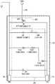
IREアブレーションシステム及びIREパルス
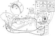
図1は、本発明の実施形態による、IREアブレーション処置で使用されるマルチチャネルIREシステム20の概略的な絵図である。以下の説明では、IREアブレーション処置は、「IREアブレーション」又は「IRE処置」とも呼ばれる。示された実施形態では、医師22は、IREシステム20を使用して、マルチチャネルIREアブレーション処置を実施している。医師22は、遠位端28が、カテーテルの長さに沿って配列された複数のアブレーション電極30を含むアブレーションカテーテル26を使用して、被験者24に対して処置を実施している。IRE Ablation System and IRE Pulses FIG. 1 is a schematic pictorial diagram of a
IREシステム20は、プロセッサ32及びIREモジュール34を含み、IREモジュールは、IRE発生器36及びIREコントローラ38を含む。以下で更に詳述するように、IRE発生器36は、IRE処置を実行するための選択された電極30に指向された電気パルスの列を発生させる。電気パルスの列の波形(タイミング及び振幅)は、IREコントローラ38によって制御される。プロセッサ32は、以下に詳述するように、IREシステム20と医師22との間の入力及び出力インターフェースを処理する。
プロセッサ32及びIREコントローラ38はそれぞれ、典型的には、プログラマブルプロセッサを含み、プログラマブルプロセッサは、本明細書に記載される機能を実行するために、ソフトウェア及び/又はファームウェアでプログラムされている。代替的に又は追加的に、それらのそれぞれ、これらの機能の少なくとも一部を実行する、ハードワイヤード及び/又はプログラム可能なハードウェア論理回路を含んでもよい。プロセッサ32及びIREコントローラ38は、単純化のために、別個のモノリシックな機能ブロックとして図に示されているが、実際には、これらの機能の一部は、図に示され、テキストに記載されている信号を受信及び出力するための好適なインターフェースを有する単一の処理及び制御ユニット内で組み合わされてもよい。いくつかの実施形態では、IREコントローラ38は、高速制御信号がIREコントローラからIRE発生器36に送信されるので、IREモジュール34内に常駐する。しかしながら、十分に高速の信号がプロセッサ32からIRE発生器36に送信され得るならば、IREコントローラ38は、プロセッサ内に常駐してもよい。
プロセッサ32及びIREモジュール34は典型的には、コンソール40内に常駐する。コンソール40は、キーボード及びマウスなどの入力装置42を含む。ディスプレイスクリーン44は、コンソール40に近接して(又はそれと一体で)位置する。ディスプレイスクリーン44は、任意選択的にタッチスクリーンを含んでもよく、それにより別の入力装置を提供することができる。
IREシステム20は、システム20内の好適なインターフェース及びデバイスに接続された、以下のモジュール(典型的には、コンソール40内に常駐する)のうちの1つ以上を更に含んでもよい。
・心電図(electrocardiogram、ECG)モジュール46は、被験者24に取り付けられたECG電極50に、ケーブル48を介して結合されている。ECGモジュール46は、被験者24の心臓52の電気活動を測定するように構成されている。
・温度モジュール54は、カテーテル26の遠位端28上の各電極30に隣接して位置する、熱電対56などの任意の温度センサに結合され、隣接する組織58の温度を測定するように構成されている。
・追跡モジュール60は、遠位端28内の1つ以上の電磁位置センサ(図示せず)に結合されている。1つ以上の磁場発生器62によって発生された外部磁場の存在下で、電磁位置センサは、センサの位置と共に変化する信号を出力する。これらの信号に基づいて、追跡モジュール60は、心臓52内の電極30の位置を確認し得る。
• An electrocardiogram (ECG)
- The
•
上記のモジュール46、54、及び60は、典型的には、アナログ構成要素及びデジタル構成要素の両方を含み、アナログ信号を受信し、デジタル信号を送信するように構成されている。各モジュールは、モジュールの機能の少なくとも一部を実行する、ハードワイヤード及び/又はプログラム可能なハードウェア論理回路を更に含んでもよい。 The
カテーテル26は、ポート又はソケットなどの電気的インターフェース64を介してコンソール40に連結されている。したがって、IRE信号は、インターフェース64を介して遠位端28に搬送される。同様に、遠位端28の位置を追跡するための信号、及び/又は組織58の温度を追跡するための信号は、インターフェース64を介してプロセッサ32によって受信され、IRE発生器36によって発生されたパルスを制御する際に、IREコントローラ38によって印加され得る。
外部電極65、すなわち「リターンパッチ」は、被験者24、典型的には被験者の胴体の皮膚上、と、IRE発生器36との間の外部に追加的に結合されてもよい。 An
プロセッサ32は、IRE処置の前、及び/又は処置中に、医師22から(又は他のユーザーから)、処置のためのセットアップパラメータ66を受信する。1つ以上の好適な入力装置42を使用して、図2~図4及び表1を参照して以下に説明するように、医師22は、IREパルス列のパラメータを設定する。医師22は更に、(IREパルス列を受信するために)活性化させるアブレーション電極30の対、及びそれらが活性化される順序を選択する。
IREアブレーションをセットアップする際、医師22はまた、心臓52のサイクルに対するIREパルスのバーストの同期のモードを選択することができる。「同期モード」と呼ばれる第1のオプションは、心臓が再充電しており、外部電気パルスに応答しない場合に、IREパルスバーストを、心臓52の不応状態の間に起こるように同期させることである。バーストは、心臓52のQRS群後に起こるように時間が合わせられるが、この遅延は、P波の前に、心臓52のT波の間にバーストが起こるように、心臓のサイクル時間の約50%である。同期モードを実施するために、IREコントローラ38は、以下の図5に示すECGモジュール46からのECG信号414に基づいて、IREパルスのバースト(単数)又はバースト(複数)の時間を合わせる。 When setting up IRE ablation,
第2の同期のオプションは非同期モードであり、IREパルスのバーストは、心臓52のタイミングとは独立して発射される。最大長さ500msを有し、典型的には200msの長さのIREバーストは、心臓が反応しない1つの短パルスとして心臓によって感じられるため、このオプションは可能である。この種の非同期的な動作は、IRE処置の簡略化及び合理化に有用であり得る。 A second synchronous option is the asynchronous mode, in which bursts of IRE pulses are fired independently of
セットアップパラメータ66を受信したことに応答して、プロセッサ32は、IREコントローラ38にこれらのパラメータを伝達し、IREコントローラ38は、医師22によって要求されたセットアップに従ってIRE信号を発生させるよう、IRE発生器36に命ずる。更に、プロセッサ32は、ディスプレイスクリーン44上にセットアップパラメータ66を表示することができる。 In response to receiving
いくつかの実施形態では、プロセッサ32は、追跡モジュール60から受信された信号に基づいて、例えば、遠位端28の現在の位置及び向きを示すように注釈付けされた、被験者の解剖学的構造の関連画像68をディスプレイ44上に表示する。代替的に又は追加的に、温度モジュール54及びECGモジュール46から受信した信号に基づいて、プロセッサ32は、各電極30における組織58の温度及び心臓52の電気活動をディスプレイスクリーン44に表示してもよい。 In some embodiments,
処置を開始するために、医師22は、カテーテル26を被験者24に挿入し、次いで、カテーテルを、制御ハンドル70を用いて、心臓52の内部又は外部の適切な部位までナビゲートする。続いて、医師22は、遠位端28を、心臓52の心筋又は心外膜組織などの組織58と接触させる。次に、IRE発生器36は、図3を参照して以下に説明されるように、複数のIRE信号を発生させる。IRE信号は、IREパルスによって発生された電流72が、各対の電極の間を流れ(双極アブレーション)、要求された不可逆的エレクトロポレーションを組織58上で7実行するように、異なるそれぞれのチャネルを介して、アブレーション電極30の対までカテーテル26を通して搬送される。 To begin treatment,
図2は、本発明の一実施形態による、双極性IREパルス100の概略図である。 FIG. 2 is a schematic diagram of a
曲線102は、IREアブレーション処置における時間tの関数としての双極性IREパルス100の電圧Vを示す。双極性IREパルスは、正のパルス104及び負のパルス106を含むが、用語「正」及び「負」は、双極性パルスが印加される2つの電極30(図1)の任意に選択された極性を指す。正のパルス104の振幅はV+と表記され、パルスの時間幅は、t+と表記される。同様に、負のパルス106の振幅はV-と表記され、パルスの時間幅は、t-と表記される。正のパルス104と負のパルス106との間の時間幅は、t間隔と表記される。双極性パルス100のパラメータの典型的な値を、以下の表1に示す。
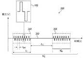
図3は、本発明の一実施形態による、双極性パルスのバースト200の概略図である。 FIG. 3 is a schematic diagram of a
IRE処置において、IRE信号は、曲線202によって示される1つ以上のバースト200として電極30にもたらされる。バースト200は、各列がNP個の双極性パルス100を含む、NT個のパルス列204を含む。パルス列204の長さはtTと表記される。パルス列204内の双極性パルス100の周期はtPPと表記され、連続する列間の間隔はΔTと表記され、その間、信号は印加されない。バースト200のパラメータの典型的な値を、以下の表1に示す。In an IRE procedure, an IRE signal is delivered to
図4A及び図4Bは、本発明の実施形態による、組み込まれたRF信号を有するIRE信号302及び304の概略図である。図4A及び図4Bに示される実施形態では、これらのアブレーションモダリティの両方から利益を得るために、RFアブレーションがIREアブレーションと組み合わされる。 4A and 4B are schematic diagrams of IRE signals 302 and 304 with embedded RF signals according to embodiments of the present invention. In the embodiment shown in Figures 4A and 4B, RF ablation is combined with IRE ablation to benefit from both of these ablation modalities.
図4Aでは、曲線306は、図2の双極性パルス100と同様に、2つの双極性パルス310と312との間のRF信号308の、時間tの関数としての電圧Vを示す。RF信号308の振幅はVRFと表記され、その周波数はfRFと表記され、双極性パルス310と312との間の分離はΔRFと表記される。典型的には、周波数fRFは350~500kHzであり、振幅VRFは10~200Vであるが、より高い又はより低い周波数及び振幅が代替的に使用されてもよい。In FIG. 4A,
図4Bでは、曲線314は、正のIREパルス318と負のIREパルス320との間のRF信号316の、時間tの関数としての電圧Vを示す。IREパルス318及び320は、図2のパルス104及び106と同様である。この実施形態では、正のパルス318と負のパルス320との間隔t間隔は、表1に示されるように伸張されている。In FIG. 4B,
RF信号308及び316の振幅及び周波数の典型的な値を表1に示す。RF信号がIRE信号に挿入されると、図4A又は図4Bのいずれかに示されるように、2つの信号の組み合わせがアブレーション処置の終了まで繰り返される。 Typical values for the amplitude and frequency of RF signals 308 and 316 are shown in Table 1. Once the RF signal is inserted into the IRE signal, the combination of the two signals is repeated until the end of the ablation procedure, as shown in either Figure 4A or Figure 4B.

IREモジュール
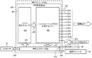
図5は、本発明の一実施形態による、IREモジュール34、及びIREモジュール34とシステム20内の他のモジュールとの接続の詳細を概略的に示すブロック図である。IRE Module FIG. 5 is a block diagram that schematically illustrates details of
図1を参照すると、IREモジュール34は、IRE発生器36及びIREコントローラ38を含む。図5では、IREモジュール34は、外側の破線のフレーム402によって描かれている。フレーム402内で、IRE発生器36は、内側の破線のフレーム404によって描かれている。IRE発生器36は、パルス発生アセンブリ406と、パルスルーティング及び計測アセンブリ408と、を含み、これらは両方とも以下の図6~図9に更に詳述される。 Referring to FIG. 1,
IREコントローラ38は、双方向信号410を介してプロセッサ32と通信し、プロセッサは、セットアップパラメータ66を反映するコマンドをIREコントローラに伝達する。IREコントローラ38は更に、パルスルーティング及び計測アセンブリ408からデジタル電圧及び電流信号412、ECGモジュール46からデジタルECG信号414、並びに温度モジュール54からデジタル温度信号416を受信し、これらの信号を双方向信号410を介してプロセッサ32に伝達する。
IREコントローラ38は、上記の図3~図5に示されるものなどのIREパルスを発生させるために、IRE発生器36に命令するセットアップパラメータ66から導出されたデジタルコマンド信号418をパルス発生アセンブリ406に伝達する。これらのIREパルスは、アナログパルス信号420として、パルスルーティング及び計測アセンブリ408に送信される。パルスルーティング及び計測アセンブリ408は、出力チャネル422を介して電極30に結合され、接続部424を介してリターンパッチ65に結合される。図5は、CH1~CH10と表記された10個の出力チャネル422を示している。以下の説明において、特定の電極は、それに結合された特定のチャネルの名前で呼ばれる。例えば、電極CH5は、チャネル422のCH5に結合された電極を指す。図5は、10個のチャネル422を示しているが、IRE発生器36は代替的に、例えば、8個、16個、若しくは20個のチャネル、又は任意の他の好適な数のチャネルなど、異なる数のチャネルを含んでもよい。
図6Aは、図示の一実施形態による、図5のパルスルーティング及び計測アセンブリ408の電気概略図である。分かりやすくするために、電流及び電圧の測定に関与する回路は省略されている。これらの回路は、以下の図7で詳述される。出力チャネル422及び接続部424は、図5と同じ表記を使用して図6Aに示されている。 FIG. 6A is an electrical schematic diagram of the pulse routing and
パルスルーティング及び計測アセンブリ408は、各出力チャネル422のための1つのモジュールを有するモジュール502を含む。隣接するモジュール502の対504が、以下の図7に詳細に示されている。 Pulse routing and
各モジュール502は、i番目のモジュールについてFOi、SOi、Ni、及びBPiと表記されたスイッチを含む。スイッチFOiは全て、IREアブレーションをチャネル間で切り替えるための高速スイッチである一方、スイッチSOi、Ni、及びBPiは、より低速のリレーであり、所与のモードのIREアブレーションのためにパルスルーティング及び計測アセンブリ408をセットアップするのに使用される。高速スイッチFOiの典型的な切替時間は、0.3μsよりも短い一方、低速リレーSOi、Ni、及びBPiは、単に3msの切替時間を要する。以下に示す実施例は、スイッチ及びリレーの使用を示す。Each
実施例1は、奇数-偶数スキームCH1-CH2、CH3-CH4、CH5-CH6、CH7-CH8、及びCH9-CH10に従った、電極の対の間のIREアブレーションのためのスイッチ及びリレーの使用を示す。ここで、双極性パルスは、各電極と第1の隣接電極との間に印加される。スイッチ及びリレーの設定を以下の表2に示す。 Example 1 demonstrates the use of switches and relays for IRE ablation between pairs of electrodes according to odd-even schemes CH1-CH2, CH3-CH4, CH5-CH6, CH7-CH8, and CH9-CH10. show. Here, a bipolar pulse is applied between each electrode and the first adjacent electrode. The switch and relay settings are shown in Table 2 below.

実施例2は、偶数-奇数スキームCH2-CH3、CH4-CH5、CH6-CH7、及びCH8-CH9に従った、電極の対の間のIREアブレーションのためのスイッチ及びリレーの使用を示す(ここで、双極性パルスは、各電極とその第2の隣接電極との間に印加される)。第1の電極と最後の電極とが隣り合って位置する円形カテーテル26では、対CH10-CH1が偶数-奇数の対に追加されてもよい。スイッチ及びリレーの設定を以下の表3に示す。 Example 2 demonstrates the use of switches and relays for IRE ablation between pairs of electrodes according to even-odd schemes CH2-CH3, CH4-CH5, CH6-CH7, and CH8-CH9 (where , a bipolar pulse is applied between each electrode and its second adjacent electrode). In a

実施例1及び実施例2を組み合わせると、実施例1の奇数-偶数スキームで最初にアブレーションを行い、次いで各高速スイッチFOiを反対の状態に(オンからオフ、及びオフからオンへ)切り替え、その後、実施例2の奇数-偶数スキームでアブレーションを行うことによって、電極30の全ての対間の高速IREアブレーションが遂行され得る。低速リレーSOi、Ni、及びBPiは、それらの状態を切り替える必要がないため、切り替えはFOiスイッチの速度で起こる。Combining Example 1 and Example 2, ablation is performed first in the odd-even scheme of Example 1, then switching each fast switch FOi to the opposite state (on to off and off to on), Fast IRE ablation between all pairs of
実施例3は、非隣接電極30間、この実施例ではCH1-CH3、CH4-CH6、及びCH7-CH9間のIREアブレーションを示す。このような構成は、組織58内により深い損傷を引き起こすために利用され得る。スイッチ及びリレーの設定を以下の表4に示す。 Example 3 shows IRE ablation between

更に、スイッチFOiを再構成することによって、電極の他の対を迅速に選択することができる。Furthermore, by reconfiguring the switches FOi , other pairs of electrodes can be quickly selected.
実施例4は、チャネルCH1とCH3との間でアブレーションを行うための代替的な方法を示す。この実施例では、アブレーション回路を閉じるためにBPライン506が利用される。スイッチ及びリレーの設定を以下の表5に示す。 Example 4 shows an alternative method for ablating between channels CH1 and CH3. In this embodiment,

実施例4では、パルスルーティング及び計測アセンブリ408内の電気経路は、変圧器二次側508及び510を直列に結合する。電極CH1とCH3との間の距離は、隣接する電極(例えば、CH1とCH2との)間の距離の2倍であるため、それぞれの電極間に同じ電界強度を有するためには、CH1とCH3との間の電圧は、隣接する電極間の電圧の2倍でなければならない。これは、これら2つの二次側に対する一次側を反対の相で駆動することによって達成される。低速スイッチSOiは全て、電極の別の対の間、例えば、CH2とCH4との間の次のアブレーションの準備の間、ON状態のままとされる。In Example 4, an electrical path in pulse routing and
上記の実施例に示されるように、リレー及び高速スイッチを使用するパルスルーティング及び計測アセンブリ408の実装により、電極30へのIREパルスのフレキシブルで高速の分配、並びに印加されるIREパルス振幅のフレキシブルな再構成が可能になる。 As shown in the examples above, the implementation of the pulse routing and
図6Bは、本発明の一実施形態による、電極30a、30b及び30cのトリオ520の間を流れるIRE電流72a、72b及び72cを示す、カテーテル26の遠位端28の概略詳細図である。電流72a、72b及び72cは、上記の表2、3及び4に示される設定を交互に使用して、パルスルーティング及び計測アセンブリ408におけるスイッチの適切な設定によって印加される。典型的には(必ずしもそうではないが)、遠位端28上の電極30のそれぞれは、この種の少なくとも1つのトリオに割り当てられる。 FIG. 6B is a schematic detail view of
この実施形態では、スイッチは、電極30a、30b及び30cなどの隣接する、第1の電極、第2の電極、及び第3の電極をそれぞれ含む電極30の1つ以上のトリオ520にわたってアブレーションが行われるように設定される。第1の電極30a及び第2の電極30bは、第1の時間間隔又は間隔のセット中に電流72aが流れる1つの隣接する電極対を形成する。第2の電極30b及び第3の電極30cは、第2の時間間隔又は間隔のセットの間に電流72bが流れる、第2の隣接する電極対を形成し、第1の電極30a及び第3の電極30cは、第3の時間間隔又は間隔の間に電流72cが流れる交互の隣接しない電極対を形成する。第1の時間間隔、第2の時間間隔、及び第3の時間間隔は、互いに分離されている。すなわち、第1の時間間隔、第2の時間間隔、及び第3の時間間隔は、互いに重ならず、第1の時間間隔、第2の時間間隔、及び第3の時間間隔のシーケンスを交互に繰り返すことができる。この種のトリオ520内の電極30の配置は、各トリオが接触する組織内に浅い病変及び深い損傷の両方を形成するのに有利であり、したがって、完全な電気ブロックの形成を容易にする。 In this embodiment, the switch allows ablation to occur over one or
典型的には、パルスルーティング及び計測アセンブリ408は、この種の複数のトリオ520にわたって同時に並行してアブレーションを可能にするように設定される。複数のトリオが選択される場合、IREパルス列は、第1の隣接する電極対及び第2の隣接する電極対に、及び全てのトリオ内の隣接しない電極に、同時に又は異なる時間に印加されてもよい。電極のトリオへのグループ化はまた、遠位端28が接触する組織の全範囲が確実にアブレーションされるようにするために、異なる期間にわたって交互に行うことができる。したがって、例えば、遠位端28が10個の電極30を含む場合、アブレーションは、それぞれがその隣接するトリオと重なる8つの異なるトリオにわたって加えられ得る。トリオの重ならないグループは、同時に作動されてもよく、重なるトリオは、異なる時間に順次作動される。 Typically, the pulse routing and
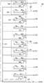
図7は、本発明の一実施形態による、パルスルーティング及び計測アセンブリ408の2つの隣接するモジュール601及びモジュール602の電気概略図である。 FIG. 7 is an electrical schematic diagram of two
モジュール601及びモジュール602が、同じ表記(504)を有する一点鎖線のフレームによって示されるように図6Aのペア504を構成する。モジュール601及びモジュール602はそれぞれ、図5に関するパルス発生アセンブリ406の一部分を含むパルス発生回路603及びパルス発生回路604によって供給される。次いで、モジュール601及びモジュール602は、図6Aのペア504のモジュール502と同様に、それぞれチャネルCH1及びチャネルCH2に供給する。図7には、モジュール間の接続605を示すために、2つのモジュール601及びモジュール602が示されている。2つのモジュールは同一である(並びにパルスルーティング及び計測アセンブリ408内の追加のモジュールと同一である)ため、モジュール601についてのみ以下に詳細に説明する。
パルス発生回路603及びパルス発生回路604の更なる詳細を以下の図8及び図9に示す。パルス発生アセンブリ406は、IRE発生器36の各チャネルのための回路603及び回路604と同様の1つのパルス発生回路を含む。パルス発生アセンブリ406は、図8に詳述される高電圧電源607を更に含む。 Further details of
パルス発生回路603は、変圧器606によってモジュール601に結合される。高速スイッチFO1並びに低速リレーSO1、N1、及びBP1は、図6Aと同様に表記される。低域フィルタ608は、パルス発生回路603によって送信されたパルス列を、変圧器606及びスイッチFO1を介して正弦波信号に変換し、CH1をRFアブレーションに使用することを可能にする。(同様に、IRE発生器36の各チャネルは、RFアブレーションに独立して使用され得る。)フィルタ608の係合はリレー610によって制御される。所与の周波数fRF及び振幅VRFを有するRF信号は、双極性パルスの列を周波数fRFで低域フィルタ608を介して放出するパルス発生回路603によって生成され、低域フィルタ608がこのパルス列を、周波数fRFを有する正弦波信号に変換する。双極性パルスの列の振幅は、正弦波信号の振幅がVRFとなるように調整される。
CH1に結合された電圧V1及び電流I1は、チャネルCH1とCH2との間の電圧、及びCH1へと流れてCH2から戻る電流として、図7に示されている。The voltage V1 and current I1 coupled toCH1 are shown in FIG. 7 as the voltage between channels CH1 and CH2 and the current flowing into CH1 and back out of CH2.
V1及びI1は、電圧を測定するための演算増幅器614と、電流検知抵抗器618にわたる電流を測定する差動増幅器616と、を含む計測モジュール612によって測定される。電圧V1は、抵抗器R1、R2、及びR3並びにアナログマルチプレクサ622を含む分圧器620から測定される。アナログマルチプレクサ622は、抵抗器R1又はR2のいずれかに結合するため、その結果、分圧器620の電圧分割比は、R1/R3又はR2/R3のいずれか一方である。計測モジュール612は、測定されたアナログ電圧V1及び電流I1をデジタル信号DV1及びDI1に変換するためのアナログデジタル変換器(analog-to-digital converter、ADC)624を更に含む。これらのデジタル信号は、デジタルアイソレータ626を介して、信号412(図5)としてIREコントローラ38に送信される。デジタルアイソレータ626は、被験者24(図1)を不必要な電圧及び電流から保護する。V1 and I1 are measured by a
スイッチFO1、リレーSO1、BP1、N1及び610、並びにアナログマルチプレクサ622は、IREコントローラ38によって駆動される。単純化のために、それぞれの制御線は、図7には示されていない。Switch FO1 , relay SO1 , BP1 , N1 and 610 and
図8は、本発明の一実施形態による、パルス発生回路603、変圧器606、及び高電圧電源607の電気概略図である。 FIG. 8 is an electrical schematic diagram of
パルス発生回路603(図7)は、内部の詳細が以下の図9に更に示される2つのスイッチ702及びスイッチ704を含む。スイッチ702は、コマンド入力706、ソース708、及びドレイン710を含む。スイッチ704は、コマンド入力712、ソース714、及びドレイン716を含む。スイッチ702及びスイッチ704は共にHブリッジの半分を形成し(当該技術分野において既知であるように)、「ハーフブリッジ」とも呼ばれる。 Pulse generator circuit 603 (FIG. 7) includes two
高電圧電源607は、IREコントローラ38からの高電圧コマンド入力724によって受信された信号に応答して、±(10~2000)Vのそれぞれ正及び負の範囲内で調整可能な正電圧V+及び負電圧V-を、それぞれの出力720及び722に供給する。高電圧電源607は、接地接続723も提供する。単一の高電圧電源607が、パルス発生アセンブリ406の全てのパルス発生回路に結合されている。代替的に、各パルス発生回路が、別個の高電圧電源に結合されてもよい。 High
スイッチ702のドレイン710は正電圧出力720に結合され、スイッチのソース708は、変圧器606の入力726に結合される。コマンド入力706がコマンド信号CMD+を受信すると、正電圧V+が、正電圧出力720からスイッチ702を介して変圧器入力726に結合される。スイッチ704のソース714は、負電圧出力722に結合され、スイッチのドレイン716は、変圧器入力726に結合される。コマンド入力712がコマンド信号CMD-を受信すると、負電圧V-が、負電圧出力722からスイッチ704を介して変圧器入力726に結合される。したがって、2つのコマンド信号CMD+及びCMD-を交互にアクティブ化することにより、正及び負のパルスがそれぞれ変圧器入力726に結合され、次いで変圧器606によってその出力728に伝送される。パルスのタイミング(パルスの幅及び分離)は、コマンド信号CMD+及びCMD-によって制御され、パルスの振幅は、高電圧コマンド入力724への高電圧コマンド信号CMDHVによって制御される。3つのコマンド信号CMD+、CMD-、及びCMDHVは全て、IREコントローラ38から受信され、IREコントローラ38は、これにより、パルスルーティング及び計測アセンブリ408のそれぞれのチャネルに供給されるパルスを制御する。The
代替の一実施形態(図示せず)では、フルHブリッジが、単極性高電圧電源を用いて使用される。この構成はまた、フルHブリッジを制御する信号に応答して、単極性源から正のパルス及び負のパルスの両方を発生させるために使用することができる。この実施形態の利点は、より単純な高電圧電源を使用することができることである一方、ハーフブリッジ及びデュアル高電圧電源の利点は、固定された接地電位、並びに独立して調整可能な正電圧及び負電圧を提供することである。 In an alternative embodiment (not shown), a full H-bridge is used with a unipolar high voltage power supply. This configuration can also be used to generate both positive and negative pulses from a unipolar source in response to signals controlling a full H-bridge. The advantage of this embodiment is that a simpler high voltage power supply can be used, while the advantage of the half-bridge and dual high voltage power supply is the fixed ground potential and the independently adjustable positive and to provide a negative voltage.
図9は、本発明の一実施形態による、スイッチ702の電気概略図である。スイッチ704は、スイッチ702と同様の様式で実装される。 FIG. 9 is an electrical schematic diagram of
スイッチ702の切り替え機能は、ゲート804、ソース708、及びドレイン710を含む電界効果トランジスタ(field-effect transistor、FET)802によって実装される。コマンド入力706は、図8に示すように結合されたソース708及びドレイン710を有するゲート804に結合される。ツェナーダイオード、ダイオード、抵抗器、及びコンデンサを含む追加の構成要素806は、回路保護器として機能する。 The switching function of
上に記載される実施形態は例として挙げたものであり、本発明は本明細書の上記で具体的に図示及び説明されるものに限定されない点が理解されよう。むしろ、本発明の範囲は、前述の本明細書に記載される様々な特徴の組み合わせ及び部分的組み合わせの両方、並びに前述の記載を読むと当業者に着想されるであろう、先行技術に開示されていないその変形及び修正を含む。 It will be appreciated that the above-described embodiments are provided by way of example, and that the invention is not limited to those specifically shown and described hereinabove. Rather, the scope of the present invention is determined by both combinations and subcombinations of the various features described herein above, as well as those disclosed in the prior art, as would occur to one of ordinary skill in the art upon reading the foregoing description. including variations and modifications thereof that have not been
〔実施の態様〕
(1) 不可逆的エレクトロポレーションのための医療装置であって、前記装置は、
患者の身体内への挿入のために構成されたプローブであって、前記プローブに沿って配設され、かつ前記身体内の組織に接触するように構成された電極の配列を含む、プローブと、
前記電極の1つ以上のトリオにわたって双極性パルスのシーケンスを印加するように構成された電気信号発生器であって、各トリオは、隣接する、第1の電極、第2の電極、及び第3の電極を含み、前記第2の電極は、前記第1の電極と前記第3の電極との間に、前記第1の電極と前記第3の電極とに隣接して配設されている、電気信号発生器と、を備え、
前記プローブが前記組織に接触している間に、前記電気信号発生器は、1つ以上の第1の時間間隔の間に前記第1の電極と前記第2の電極との間に、かつ1つ以上の第2の時間間隔の間に前記第2の電極と前記第3の電極との間に、かつ1つ以上の第3の時間間隔の間に前記第1の電極と前記第3の電極との間に、前記双極性パルスの前記シーケンスを印加し、前記第1の時間間隔、前記第2の時間間隔、及び前記第3の時間間隔が、互いに分離されている、装置。
(2) 前記電気信号発生器は、前記第1の時間間隔、前記第2の時間間隔、及び前記第3の時間間隔の間に前記双極性パルスの前記シーケンスを交互に印加するように構成されている、実施態様1に記載の装置。
(3) 前記1つ以上のトリオは、前記電極の複数のトリオを含む、実施態様1に記載の装置。
(4) 前記複数のトリオのうちの少なくともいくつかは、互いに重ならず、前記電気信号発生器は、前記双極性パルスの前記シーケンスを互いに重ならない前記トリオに同時に印加するように構成されている、実施態様3に記載の装置。
(5) 前記複数のトリオのうちの少なくともいくつかは、互いに重なり合い、前記電気信号発生器は、前記双極性パルスの前記シーケンスを互いに重なり合う前記トリオに順次印加するように構成されている、実施態様3に記載の装置。[Mode of implementation]
(1) A medical device for irreversible electroporation, said device comprising:
a probe configured for insertion into the body of a patient, the probe comprising an array of electrodes disposed along the probe and configured to contact tissue within the body;
an electrical signal generator configured to apply a sequence of bipolar pulses across one or more trios of said electrodes, each trio being adjacent a first electrode, a second electrode and a third electrode; wherein the second electrode is disposed between the first electrode and the third electrode and adjacent to the first electrode and the third electrode; an electrical signal generator;
While the probe is in contact with the tissue, the electrical signal generator is placed between the first electrode and the second electrode for one or more first time intervals, and one between said second electrode and said third electrode during one or more second time intervals and between said first electrode and said third electrode during one or more third time intervals; applying said sequence of said bipolar pulses between electrodes, wherein said first time interval, said second time interval and said third time interval are separated from each other.
(2) the electrical signal generator is configured to alternately apply the sequence of the bipolar pulses during the first time interval, the second time interval and the third time interval; 2. The apparatus of embodiment 1, wherein the apparatus is
Aspect 3. The apparatus of aspect 1, wherein the one or more trios comprises a plurality of trios of the electrodes.
(4) at least some of the plurality of trios are non-overlapping, and the electrical signal generator is configured to simultaneously apply the sequence of the bipolar pulses to the non-overlapping trios; A device according to claim 3.
(5) Embodiment wherein at least some of said plurality of trios overlap each other and said electrical signal generator is configured to sequentially apply said sequence of said bipolar pulses to said mutually overlapping trios. 3. The device according to 3.
(6) 前記双極性パルスは、前記組織内に不可逆的電気泳動(IRE)を引き起こすのに十分な振幅を有する、実施態様1に記載の装置。
(7) 前記シーケンスにおける前記双極性パルスの各々の前記振幅は、少なくとも200Vであり、前記双極性パルスの各々の持続時間は、20μs未満である、実施態様6に記載の装置。
(8) 前記電気信号発生器は、前記電極によって接触された前記組織を熱アブレーションするのに十分な電力を有する高周波(RF)信号を前記電極に印加するように更に構成されている、実施態様6に記載の装置。
(9) 前記電気信号発生器は、双極性パルスの前記シーケンスを含む複数のパルス列を発生させるように構成されており、前記パルス列は、前記双極性パルスが印加されない間隔によって分離されている、実施態様1に記載の装置。
(10) 前記プローブは、前記患者の心臓内の前記組織に接触し、前記心臓内の前記組織をアブレーションするために前記双極性パルスの前記シーケンスを印加するように構成されている、実施態様1に記載の装置。Aspect 6. The apparatus of Aspect 1, wherein the bipolar pulse has an amplitude sufficient to induce irreversible electrophoresis (IRE) in the tissue.
7. The apparatus of claim 6, wherein the amplitude of each of the bipolar pulses in the sequence is at least 200V and the duration of each of the bipolar pulses is less than 20 μs.
(8) Embodiment wherein the electrical signal generator is further configured to apply a radio frequency (RF) signal to the electrodes having sufficient power to thermally ablate the tissue contacted by the electrodes. 7. Apparatus according to 6.
(9) wherein the electrical signal generator is configured to generate a plurality of pulse trains comprising the sequence of bipolar pulses, the pulse trains being separated by intervals during which the bipolar pulses are not applied; A device according to aspect 1.
Embodiment 1, wherein the probe is configured to contact the tissue within the patient's heart and apply the sequence of the bipolar pulses to ablate the tissue within the heart. The apparatus described in .
(11) 前記電気信号発生器は、前記心臓の拍動に対して非同期的に前記信号を印加するように構成されている、実施態様10に記載の装置。
(12) 前記電気信号発生器は、前記心臓の拍動に対して同期的に前記信号を印加するように構成されている、実施態様10に記載の装置。
(13) 前記プローブは、前記電極に隣接する複数の温度センサを含み、前記電気信号発生器は、前記温度センサによって測定された温度に応答して前記双極性パルスを印加するように構成されている、実施態様1に記載の装置。
(14) 前記電気信号発生器は、前記双極性パルスの前記第1のシーケンスの印加と、前記第2のシーケンスの印加とを3ミリ秒以内に切り替えるように構成されたスイッチのネットワークを含む、実施態様1に記載の装置。
(15) 前記電気信号発生器は、前記双極性パルスを発生させるパルス発生アセンブリと、前記双極性パルスを、複数の出力チャネルを介して前記電極に送るように構成されたパルスルーティング及び計測アセンブリと、を含む、実施態様1に記載の装置。
Clause 12. The apparatus of Clause 10, wherein the electrical signal generator is configured to apply the signal synchronously with the beat of the heart.
(13) the probe includes a plurality of temperature sensors adjacent to the electrodes, and the electrical signal generator is configured to apply the bipolar pulses in response to temperatures measured by the temperature sensors; 2. The apparatus of embodiment 1, wherein the apparatus is
(14) the electrical signal generator includes a network of switches configured to switch between application of the first sequence of bipolar pulses and application of the second sequence of bipolar pulses within 3 milliseconds; A device according to embodiment 1.
(15) the electrical signal generator comprises a pulse generation assembly for generating the bipolar pulses; and a pulse routing and measurement assembly configured to deliver the bipolar pulses to the electrodes via a plurality of output channels. 3. The apparatus of embodiment 1, comprising:
(16) 患者の身体内の組織をアブレーションするための方法であって、前記方法は、
プローブを前記身体内に挿入することであって、前記プローブは、前記プローブに沿って配設され、かつ前記組織に接触するように構成された複数の電極を含む、挿入することと、
前記電極の1つ以上のトリオにわたって前記組織に双極性パルスのシーケンスを印加することであって、各トリオは、隣接する、第1の電極、第2の電極、及び第3の電極を含み、前記第2の電極は、前記第1の電極と前記第3の電極との間に、前記第1の電極と前記第3の電極とに隣接して配設され、前記双極性パルスの前記シーケンスは、1つ以上の第1の時間間隔の間に前記第1の電極と前記第2の電極との間に、かつ1つ以上の第2の時間間隔の間に前記第2の電極と前記第3の電極との間に、かつ1つ以上の第3の時間間隔の間に前記第1の電極と前記第3の電極との間に印加され、前記第1の時間間隔、前記第2の時間間隔、及び前記第3の時間間隔は、互いに分離されている、印加することと、を含む、方法。
(17) 前記シーケンスを印加することは、前記第1の時間間隔、前記第2の時間間隔、及び前記第3の時間間隔の間に前記双極性パルスの前記シーケンスを交互に印加することを含む、実施態様16に記載の方法。
(18) 前記1つ以上のトリオは、前記電極の複数のトリオを含む、実施態様16に記載の方法。
(19) 前記複数のトリオのうちの少なくともいくつかは、互いに重ならず、前記シーケンスを印加することは、前記双極性パルスの前記シーケンスを互いに重ならない前記トリオに同時に印加することを含む、実施態様18に記載の方法。
(20) 前記複数のトリオのうちの少なくともいくつかは、互いに重なり合い、前記シーケンスを印加することは、前記双極性パルスの前記シーケンスを互いに重なり合う前記トリオに順次印加することを含む、実施態様18に記載の装置。(16) A method for ablating tissue within a patient's body, the method comprising:
inserting a probe into the body, the probe including a plurality of electrodes disposed along the probe and configured to contact the tissue;
applying a sequence of bipolar pulses to the tissue over one or more trios of the electrodes, each trio comprising adjacent first, second, and third electrodes; said second electrode disposed between said first electrode and said third electrode and adjacent said first electrode and said third electrode; and said sequence of said bipolar pulses is between said first electrode and said second electrode during one or more first time intervals and between said second electrode and said applied between said first electrode and said third electrode for one or more third time intervals, said first time interval, said second and said third time interval are separated from each other.
(17) applying the sequence includes alternately applying the sequence of the bipolar pulses during the first time interval, the second time interval and the third time interval; 17. The method of claim 16.
18. The method of embodiment 16, wherein said one or more trios comprises a plurality of trios of said electrodes.
(19) wherein at least some of said plurality of trios are non-overlapping, and said applying said sequence comprises simultaneously applying said sequence of said bipolar pulses to said non-overlapping trios; 19. The method of aspect 18.
20. According to embodiment 18, at least some of said plurality of trios overlap each other, and said applying said sequence comprises sequentially applying said sequence of said bipolar pulses to said trios that overlap each other. Apparatus as described.
(21) 前記双極性パルスは、前記組織内に不可逆的電気泳動(IRE)を引き起こすのに十分な振幅を有する、実施態様16に記載の方法。
(22) 前記シーケンス内の前記双極性パルスの各々の前記振幅は、少なくとも200Vであり、前記双極性パルスの各々の持続時間は、20μs未満である、実施態様21に記載の方法。
(23) 前記プローブを挿入することは、前記患者の心臓内の前記組織に接触することを含み、前記双極性パルスの前記シーケンスを印加することで、前記心臓内の前記組織をアブレーションする、実施態様16に記載の方法。(21) The method of embodiment 16, wherein said bipolar pulse has an amplitude sufficient to induce irreversible electrophoresis (IRE) in said tissue.
22. The method of embodiment 21, wherein the amplitude of each of the bipolar pulses in the sequence is at least 200V and the duration of each of the bipolar pulses is less than 20 μs.
(23) inserting the probe comprises contacting the tissue within the patient's heart, and applying the sequence of the bipolar pulses to ablate the tissue within the heart; 17. The method of aspect 16.
Claims (15)
Translated fromJapanese患者の身体内への挿入のために構成されたプローブであって、前記プローブに沿って配設され、かつ前記身体内の組織に接触するように構成された電極の配列を含む、プローブと、
前記電極の1つ以上のトリオにわたって双極性パルスのシーケンスを印加するように構成された電気信号発生器であって、各トリオは、隣接する、第1の電極、第2の電極、及び第3の電極を含み、前記第2の電極は、前記第1の電極と前記第3の電極との間に、前記第1の電極と前記第3の電極とに隣接して配設されている、電気信号発生器と、を備え、
前記プローブが前記組織に接触している間に、前記電気信号発生器は、1つ以上の第1の時間間隔の間に前記第1の電極と前記第2の電極との間に、かつ1つ以上の第2の時間間隔の間に前記第2の電極と前記第3の電極との間に、かつ1つ以上の第3の時間間隔の間に前記第1の電極と前記第3の電極との間に、前記双極性パルスの前記シーケンスを印加し、前記第1の時間間隔、前記第2の時間間隔、及び前記第3の時間間隔が、互いに分離されている、装置。A medical device for irreversible electroporation, said device comprising:
a probe configured for insertion into the body of a patient, the probe comprising an array of electrodes disposed along the probe and configured to contact tissue within the body;
an electrical signal generator configured to apply a sequence of bipolar pulses across one or more trios of said electrodes, each trio being adjacent a first electrode, a second electrode and a third electrode; wherein the second electrode is disposed between the first electrode and the third electrode and adjacent to the first electrode and the third electrode; an electrical signal generator;
While the probe is in contact with the tissue, the electrical signal generator is placed between the first electrode and the second electrode for one or more first time intervals, and one between said second electrode and said third electrode during one or more second time intervals and between said first electrode and said third electrode during one or more third time intervals; applying said sequence of said bipolar pulses between electrodes, wherein said first time interval, said second time interval and said third time interval are separated from each other.
Applications Claiming Priority (2)
| Application Number | Priority Date | Filing Date | Title |
|---|---|---|---|
| US17/229,498US12102374B2 (en) | 2019-12-03 | 2021-04-13 | Pulse generator for irreversible electroporation with switchable pulse application |
| US17/229,498 | 2021-04-13 |
Publications (1)
| Publication Number | Publication Date |
|---|---|
| JP2022162997Atrue JP2022162997A (en) | 2022-10-25 |
Family
ID=81307299
Family Applications (1)
| Application Number | Title | Priority Date | Filing Date |
|---|---|---|---|
| JP2022065571APendingJP2022162997A (en) | 2021-04-13 | 2022-04-12 | Pulse generator for irreversible electroporation with switchable pulse application |
Country Status (4)
| Country | Link |
|---|---|
| EP (1) | EP4074272B1 (en) |
| JP (1) | JP2022162997A (en) |
| CN (1) | CN115192177A (en) |
| IL (1) | IL291970B2 (en) |
Families Citing this family (4)
| Publication number | Priority date | Publication date | Assignee | Title |
|---|---|---|---|---|
| US12076071B2 (en) | 2020-08-14 | 2024-09-03 | Kardium Inc. | Systems and methods for treating tissue with pulsed field ablation |
| WO2022176202A1 (en)* | 2021-02-22 | 2022-08-25 | 日本ライフライン株式会社 | Power supply device and ablation system |
| CN116196081B (en)* | 2023-02-07 | 2024-02-23 | 上海玮启医疗器械有限公司 | Circuit switching system and method for pulse ablation catheter |
| CN116158838A (en)* | 2023-03-16 | 2023-05-26 | 上海圣达济医疗科技有限公司 | A pulse generating system for irreversible electroporation |
Citations (4)
| Publication number | Priority date | Publication date | Assignee | Title |
|---|---|---|---|---|
| JP2012521863A (en)* | 2009-03-31 | 2012-09-20 | アンジオダイナミツクス・インコーポレイテツド | System and method for treatment area estimation and interactive patient treatment planning of treatment devices |
| US20140066913A1 (en)* | 2012-09-06 | 2014-03-06 | Medtronic Ablation Frontiers Llc | Ablation device and method for electroporating tissue cells |
| US20210052325A1 (en)* | 2018-05-07 | 2021-02-25 | Farapulse, Inc. | Epicardial ablation catheter |
| CN112568989A (en)* | 2019-12-03 | 2021-03-30 | 伯恩森斯韦伯斯特(以色列)有限责任公司 | Pulse generator for irreversible electroporation |
Family Cites Families (3)
| Publication number | Priority date | Publication date | Assignee | Title |
|---|---|---|---|---|
| EP3030185B1 (en)* | 2013-08-06 | 2023-05-10 | Memorial Sloan Kettering Cancer Center | System and computer-accessible medium for in-vivo tissue ablation and/or damage |
| US11364072B2 (en)* | 2017-01-27 | 2022-06-21 | Medtronic, Inc. | Catheter electrodes for energy management |
| WO2019217433A1 (en)* | 2018-05-07 | 2019-11-14 | Farapulse, Inc. | Systems, apparatuses and methods for delivery of ablative energy to tissue |
- 2022
- 2022-04-05ILIL291970Apatent/IL291970B2/enunknown
- 2022-04-12JPJP2022065571Apatent/JP2022162997A/enactivePending
- 2022-04-12EPEP22167786.7Apatent/EP4074272B1/enactiveActive
- 2022-04-13CNCN202210384305.1Apatent/CN115192177A/enactivePending
Patent Citations (4)
| Publication number | Priority date | Publication date | Assignee | Title |
|---|---|---|---|---|
| JP2012521863A (en)* | 2009-03-31 | 2012-09-20 | アンジオダイナミツクス・インコーポレイテツド | System and method for treatment area estimation and interactive patient treatment planning of treatment devices |
| US20140066913A1 (en)* | 2012-09-06 | 2014-03-06 | Medtronic Ablation Frontiers Llc | Ablation device and method for electroporating tissue cells |
| US20210052325A1 (en)* | 2018-05-07 | 2021-02-25 | Farapulse, Inc. | Epicardial ablation catheter |
| CN112568989A (en)* | 2019-12-03 | 2021-03-30 | 伯恩森斯韦伯斯特(以色列)有限责任公司 | Pulse generator for irreversible electroporation |
Also Published As
| Publication number | Publication date |
|---|---|
| CN115192177A (en) | 2022-10-18 |
| IL291970B2 (en) | 2025-09-01 |
| EP4074272B1 (en) | 2023-08-23 |
| EP4074272A1 (en) | 2022-10-19 |
| IL291970A (en) | 2022-11-01 |
| IL291970B1 (en) | 2025-05-01 |
Similar Documents
| Publication | Publication Date | Title |
|---|---|---|
| JP7562670B2 (en) | Pulse generator for irreversible electroporation | |
| JP7430794B2 (en) | Adjust the delivery of irreversible electroporation pulses depending on the transferred energy | |
| JP7562394B2 (en) | Pulse generator for irreversible electroporation | |
| US12137968B2 (en) | Methods and apparatus for multi-catheter tissue ablation | |
| JP2022162997A (en) | Pulse generator for irreversible electroporation with switchable pulse application | |
| JP7658522B2 (en) | IRE temperature control | |
| US12102374B2 (en) | Pulse generator for irreversible electroporation with switchable pulse application |
Legal Events
| Date | Code | Title | Description |
|---|---|---|---|
| RD04 | Notification of resignation of power of attorney | Free format text:JAPANESE INTERMEDIATE CODE: A7424 Effective date:20250130 | |
| A621 | Written request for application examination | Free format text:JAPANESE INTERMEDIATE CODE: A621 Effective date:20250204 | |
| A131 | Notification of reasons for refusal | Free format text:JAPANESE INTERMEDIATE CODE: A131 Effective date:20250916 | |
| A977 | Report on retrieval | Free format text:JAPANESE INTERMEDIATE CODE: A971007 Effective date:20250917 |