JP2022162167A - Illumination system - Google Patents
Illumination systemDownload PDFInfo
- Publication number
- JP2022162167A JP2022162167AJP2022136130AJP2022136130AJP2022162167AJP 2022162167 AJP2022162167 AJP 2022162167AJP 2022136130 AJP2022136130 AJP 2022136130AJP 2022136130 AJP2022136130 AJP 2022136130AJP 2022162167 AJP2022162167 AJP 2022162167A
- Authority
- JP
- Japan
- Prior art keywords
- lighting
- control
- image
- led
- identification information
- Prior art date
- Legal status (The legal status is an assumption and is not a legal conclusion. Google has not performed a legal analysis and makes no representation as to the accuracy of the status listed.)
- Granted
Links
Images


Classifications
- H—ELECTRICITY
- H05—ELECTRIC TECHNIQUES NOT OTHERWISE PROVIDED FOR
- H05B—ELECTRIC HEATING; ELECTRIC LIGHT SOURCES NOT OTHERWISE PROVIDED FOR; CIRCUIT ARRANGEMENTS FOR ELECTRIC LIGHT SOURCES, IN GENERAL
- H05B47/00—Circuit arrangements for operating light sources in general, i.e. where the type of light source is not relevant
- H05B47/10—Controlling the light source
- H05B47/175—Controlling the light source by remote control
- H05B47/19—Controlling the light source by remote control via wireless transmission
- H—ELECTRICITY
- H05—ELECTRIC TECHNIQUES NOT OTHERWISE PROVIDED FOR
- H05B—ELECTRIC HEATING; ELECTRIC LIGHT SOURCES NOT OTHERWISE PROVIDED FOR; CIRCUIT ARRANGEMENTS FOR ELECTRIC LIGHT SOURCES, IN GENERAL
- H05B47/00—Circuit arrangements for operating light sources in general, i.e. where the type of light source is not relevant
- H05B47/10—Controlling the light source
- H05B47/175—Controlling the light source by remote control
- H05B47/196—Controlling the light source by remote control characterised by user interface arrangements
- H—ELECTRICITY
- H05—ELECTRIC TECHNIQUES NOT OTHERWISE PROVIDED FOR
- H05B—ELECTRIC HEATING; ELECTRIC LIGHT SOURCES NOT OTHERWISE PROVIDED FOR; CIRCUIT ARRANGEMENTS FOR ELECTRIC LIGHT SOURCES, IN GENERAL
- H05B47/00—Circuit arrangements for operating light sources in general, i.e. where the type of light source is not relevant
- H05B47/10—Controlling the light source
- H05B47/175—Controlling the light source by remote control
- H05B47/198—Grouping of control procedures or address assignation to light sources
- H05B47/199—Commissioning of light sources
- Y—GENERAL TAGGING OF NEW TECHNOLOGICAL DEVELOPMENTS; GENERAL TAGGING OF CROSS-SECTIONAL TECHNOLOGIES SPANNING OVER SEVERAL SECTIONS OF THE IPC; TECHNICAL SUBJECTS COVERED BY FORMER USPC CROSS-REFERENCE ART COLLECTIONS [XRACs] AND DIGESTS
- Y02—TECHNOLOGIES OR APPLICATIONS FOR MITIGATION OR ADAPTATION AGAINST CLIMATE CHANGE
- Y02B—CLIMATE CHANGE MITIGATION TECHNOLOGIES RELATED TO BUILDINGS, e.g. HOUSING, HOUSE APPLIANCES OR RELATED END-USER APPLICATIONS
- Y02B20/00—Energy efficient lighting technologies, e.g. halogen lamps or gas discharge lamps
- Y02B20/40—Control techniques providing energy savings, e.g. smart controller or presence detection
Landscapes
- Engineering & Computer Science (AREA)
- Computer Networks & Wireless Communication (AREA)
- Circuit Arrangement For Electric Light Sources In General (AREA)
- Selective Calling Equipment (AREA)
- Remote Monitoring And Control Of Power-Distribution Networks (AREA)
Abstract
Translated fromJapaneseDescription
Translated fromJapanese本発明は、照明システムに関し、特に無線通信により照明装置を制御する技術に関する。 The present invention relates to a lighting system, and more particularly to technology for controlling a lighting device by wireless communication.
従来の無線式照明システムでは、1つの照明装置を、これに対応する1つの照明制御装置を用いて無線通信により制御する技術が多く用いられている(例えば、特許文献1参照)。具体的には、照明制御装置は、送信部、入力部、及び第1制御部を有し、第1制御部は、入力部から入力される指令に基づいて、点灯信号、消灯信号、及び調光信号の少なくとも何れか1つの信号を含んだ制御信号を生成すると共に、その制御信号を、送信部を通じて照明装置へ送信する。照明装置は、受信部、LED(Light Emitting Diode)等の発光部、及び第2制御部を有し、照明制御装置の送信部から送信される制御信号を受信部が受信したとき、第2制御部は、受信部が受信した制御信号に応じた照明制御(点灯、消灯、調光等)を発光部に対して行う。 In conventional wireless lighting systems, a technique of controlling one lighting device by wireless communication using one corresponding lighting control device is often used (see
オフィス等の広い空間では、複数の照明装置が必要となる。複数の照明装置を無線通信により個別に制御しようとした場合、従来の無線式照明システムでは、照明装置の各々に対して1つの照明制御装置が必要となる。このため、照明装置の数が多くなると、全ての照明装置を個別に制御することは実質的に不可能となる。 A large space such as an office requires a plurality of lighting devices. When attempting to individually control a plurality of lighting devices by wireless communication, a conventional wireless lighting system requires one lighting control device for each of the lighting devices. Therefore, when the number of lighting devices increases, it becomes substantially impossible to control all the lighting devices individually.
例えば、1つの照明制御装置により、オフィス等の空間に設置されている全ての照明装置に対して同じ照明制御を行うことは可能である。しかし、この様な制御では、照明装置が配置されている位置や照明の時間帯によっては、照明装置の照度が適切でなく、電力が無駄に消費されることになる。 For example, one lighting control device can perform the same lighting control for all lighting devices installed in a space such as an office. However, in such control, the illuminance of the lighting device is not appropriate depending on the position where the lighting device is arranged and the lighting time zone, and power is wasted.
そこで本発明の目的は、複数の照明装置を個別に制御すると共にそれらの制御を一括して管理することが可能な照明システムを提供することである。 SUMMARY OF THE INVENTION Accordingly, an object of the present invention is to provide a lighting system capable of individually controlling a plurality of lighting devices and collectively managing the control thereof.
本発明に係る照明システムは、第1識別情報を備え、無線通信により制御される複数の照明装置と、前記照明装置を無線通信により制御するための照明制御情報を送信する照明制御装置と、を備えた照明システムであって、前記照明制御装置は、画面が表示される表示部を備え、ユーザは、前記表示部において、複数の照明装置の配置位置が示された配灯画像を表示させずに、前記第1識別情報が関連付けられる照明装置の象徴画像を作成し、前記照明制御装置は、前記象徴画像に関連付けられた前記照明制御情報に基づいて、制御信号を送信する。 A lighting system according to the present invention includes a plurality of lighting devices that are provided with first identification information and controlled by wireless communication, and a lighting control device that transmits lighting control information for controlling the lighting devices by wireless communication. wherein the lighting control device includes a display unit on which a screen is displayed, and the user does not display a lighting arrangement image showing the arrangement positions of the plurality of lighting devices on the display unit. Then, a symbolic image of the lighting device associated with the first identification information is created, and the lighting control device transmits a control signal based on the lighting control information associated with the symbolic image.
本発明に係る照明システムによれば、複数の照明装置を個別に制御すると共にそれらの制御を一括して管理することが出来る。 According to the lighting system of the present invention, it is possible to individually control a plurality of lighting devices and collectively manage the control thereof.
本発明の新規な特徴を添付の請求の範囲に記述するが、本発明は、構成及び内容の両方に関し、本発明の他の目的及び特徴と併せ、図面を参照した以下の詳細な説明により更によく理解されるであろう。 While the novel features of the invention are set forth in the appended claims, the invention, both as to construction and content, together with other objects and features of the invention, will be further developed by the following detailed description with reference to the drawings. will be well understood.
先ず、本発明の実施形態を列記して説明する。 First, embodiments of the present invention will be listed and described.
本発明の実施形態に係る照明制御装置は、無線通信により複数の照明装置を制御する装置であって、送信部と、制御部と、表示部と、入力部と、記憶部とを有する。送信部は、点灯信号、消灯信号、及び調光信号の少なくとも何れか1つの信号を含んだ制御信号を送信する。ここで、制御対象である複数の照明装置は、それぞれの識別を可能にする第1識別情報を持っている。 A lighting control device according to an embodiment of the present invention is a device that controls a plurality of lighting devices by wireless communication, and includes a transmission section, a control section, a display section, an input section, and a storage section. The transmitter transmits a control signal including at least one of a lighting signal, a lighting-out signal, and a dimming signal. Here, the plurality of lighting devices to be controlled have first identification information that enables their identification.
そして、制御部は、制御(i)~(v)を実行する。制御(i)において、制御部は、少なくとも1つの照明装置と対応付けられることになる象徴画像を、表示部に表示させる。制御(ii)において、制御部は、第1識別情報を取得すると共に、取得した第1識別情報を表示部に表示させる。制御(iii)において、制御部は、表示部に表示された第1識別情報が、入力部からの操作により象徴画像と重なる位置にドラッグされたとき、ドラッグされた第1識別情報を、その第1識別情報が重ねられた象徴画像に関連付けて記憶部に記憶させ、これにより、その第1識別情報を持つ照明装置と象徴画像とが互いに対応付けられる。制御(iv)において、制御部は、象徴画像に関連付けて、その象徴画像に制御(iii)にて対応付けられた照明装置の制御に関する照明制御情報を、記憶部に記憶させる。制御(v)において、制御部は、象徴画像に関連付けられた第1識別情報及び照明制御情報に基づいて制御信号を生成すると共に、生成した制御信号を、送信部を通じて、象徴画像に対応付けられた照明装置に送信する。 The control unit then executes controls (i) to (v). In control (i), the control unit causes the display unit to display a symbolic image to be associated with at least one lighting device. In control (ii), the control unit acquires the first identification information and causes the display unit to display the acquired first identification information. In control (iii), when the first identification information displayed on the display unit is dragged to a position overlapping the symbolic image by an operation from the input unit, the control unit changes the dragged first identification information to its first identification information. 1 identification information is stored in the storage unit in association with the superimposed symbolic image, whereby the lighting device having the first identification information and the symbolic image are associated with each other. In control (iv), the control unit associates with the symbolic image and causes the storage unit to store lighting control information regarding control of the lighting device associated with the symbolic image in control (iii). In control (v), the control unit generates a control signal based on the first identification information and the lighting control information associated with the symbolic image, and transmits the generated control signal to the symbolic image through the transmission unit. sent to the lighting device.
上記照明制御装置によれば、ユーザによる入力部からの簡単な操作により、照明制御情報に対して、少なくとも1つの第1識別情報が象徴画像を介して関連付けられる。従って、複数の照明装置を、照明制御情報との所望の関連態様で制御することが可能になる。ここで、所望の関連態様には、照明装置の各々に照明制御情報が関連付けられた態様、照明装置のグループに照明制御情報が関連付けられた態様、及びこれらを組み合わせた態様が含まれる。この様に、上記照明制御装置によれば、複数の照明装置を個別に制御すると共に、それらの制御を1つの照明制御装置で一括して管理することが可能になる。又、上記照明制御装置においては、象徴画像の変更(例えば、同じ照明制御を行いたいエリアの変更)等、照明制御に関する設定の変更が容易である。更には、複数の照明装置が無線通信により制御されるため、有線式のシステムで構築されていた回路(配線)が不要となる。 According to the lighting control device described above, at least one piece of first identification information is associated with the lighting control information through the symbolic image by a simple operation from the input unit by the user. Therefore, it becomes possible to control a plurality of lighting devices in a desired related manner with the lighting control information. Here, the desired association mode includes a mode in which lighting control information is associated with each lighting device, a mode in which lighting control information is associated with a group of lighting devices, and a mode in which these are combined. As described above, according to the lighting control device, it is possible to individually control a plurality of lighting devices and collectively manage the control of the lighting devices by one lighting control device. In addition, in the lighting control device, it is easy to change the settings related to the lighting control, such as changing the symbolic image (for example, changing the area where the same lighting control is desired). Furthermore, since a plurality of lighting devices are controlled by wireless communication, the circuit (wiring) constructed in a wired system becomes unnecessary.
好ましくは、複数の照明装置の配置が示された配灯画像上において、象徴画像は、その象徴画像と重なる位置に配された少なくとも1つの照明装置に対応していることを象徴する画像であり、制御(i)の前に、制御部は、配灯画像を表示部に表示させる制御(vi)を更に実行する。そして、制御(i)において、制御部は、表示部に、象徴画像を配灯画像に重ねて表示させる。 Preferably, the symbolic image is an image that symbolizes that the symbolic image corresponds to at least one lighting device arranged at a position overlapping with the symbolic image on the lighting arrangement image showing the arrangement of the plurality of lighting devices. , Prior to control (i), the control unit further executes control (vi) for displaying the lighting image on the display unit. Then, in control (i), the control unit causes the display unit to display the symbolic image superimposed on the light distribution image.
好ましくは、制御(ii)において、制御部は、取得した第1識別情報に対応させて、その第1識別情報を持った照明装置を点灯させるための点灯信号を発生させる第1スイッチを、表示部に表示させる。 Preferably, in control (ii), the control unit displays a first switch for generating a lighting signal for lighting the lighting device having the first identification information in correspondence with the acquired first identification information. displayed in the department.
この様な構成によれば、ユーザは、入力部からの第1スイッチの操作により、照明装置を点灯させて、操作した第1スイッチに対応する照明装置の実際の位置を確認することが可能になる。従って、ユーザは、操作した第1スイッチに対応させて表示されている第1識別情報を、確認した実際の位置に基づいて、関連付けんとする象徴画像にドラッグすることが出来る。この様なユーザのドラッグ操作が実行されたとき、制御部は制御(iii)を実行する。よって、第1識別情報が、象徴画像に対して正確に関連付けられる。 According to such a configuration, the user can turn on the lighting device by operating the first switch from the input section and confirm the actual position of the lighting device corresponding to the operated first switch. Become. Therefore, the user can drag the first identification information displayed in association with the operated first switch to the symbolic image to be associated based on the confirmed actual position. When such a user's drag operation is performed, the control unit executes control (iii). Thus, the first identification information is accurately associated with the symbolic image.
上記照明制御装置において、象徴画像は、同じ照明制御が実行される照明装置のエリアを表すエリア画像であってもよい。この場合、制御(iii)において、制御部は、エリア画像で表されるエリア内の全ての照明装置の第1識別情報を、エリア画像に関連付けて記憶部に記憶させる。又、制御(v)において、制御部は、エリア画像で表されるエリア内の全ての照明装置に対して、送信部を通じて制御信号を送信する。 In the lighting control device described above, the symbolic image may be an area image representing an area of the lighting device in which the same lighting control is performed. In this case, in control (iii), the control unit causes the storage unit to store the first identification information of all lighting devices in the area represented by the area image in association with the area image. Also, in control (v), the control unit transmits control signals through the transmission unit to all lighting devices within the area represented by the area image.
この様な構成によれば、ユーザによる入力部からの簡単な操作により、所望のエリア内で全ての照明装置に対して同じ照明制御を行うための設定が遂行される。 According to such a configuration, the setting for performing the same lighting control for all the lighting devices in the desired area is performed by a simple operation from the input unit by the user.
上記照明制御装置の好ましい具体的構成において、照明制御装置は、無線通信中の照明装置から送信される信号であって第1識別情報を含んだ情報信号を受信する、受信部を更に有する。そして、制御(ii)において、制御部は、受信部に情報信号を受信させることにより、情報信号に含まれる第1識別情報を取得し、取得した第1識別情報を表示部に表示させる。 In a preferred specific configuration of the lighting control device, the lighting control device further includes a receiving section that receives an information signal including the first identification information, which is a signal transmitted from the lighting device during wireless communication. Then, in control (ii), the control unit acquires the first identification information included in the information signal by causing the receiving unit to receive the information signal, and causes the display unit to display the acquired first identification information.
上記照明制御装置の好ましい他の具体的構成において、照明制御装置は、QRコード(登録商標)を読み込む読込み部を更に有し、照明装置の各々には、第1識別情報に対応するQRコード(登録商標)が設けられ、記憶部には、第1識別情報とQRコード(登録商標)との対応関係を表すテーブルが記憶されている。そして、制御(ii)において、制御部は、テーブルに基づいて、読込み部により読み込まれたQRコード(登録商標)に対応する第1識別情報を取得し、取得した第1識別情報を表示部に表示させる。 In another preferred specific configuration of the lighting control device, the lighting control device further has a reading unit for reading a QR code (registered trademark), and each of the lighting devices has a QR code ( A registered trademark) is provided, and the storage unit stores a table representing the correspondence relationship between the first identification information and the QR code (registered trademark). Then, in control (ii), the control unit acquires the first identification information corresponding to the QR code (registered trademark) read by the reading unit based on the table, and displays the acquired first identification information on the display unit. display.
この様な構成によれば、この構成を持った照明制御装置と複数の照明装置とを備えた照明システムが、例えば隣接する複数の店舗の各々に採用された場合でも、照明制御装置の各々の表示部には、この照明制御装置と共に同じ照明システムを構成している照明装置が持つ第1識別情報のみが表示されることになる。よって、ユーザであるシステム管理者が、自身が所有する照明システムとは別の照明システムから第1識別情報を取得し、その第1識別情報を象徴画像に誤って関連付けてしまうといった不具合が、上記具体的構成によれば防止される。 According to such a configuration, even if a lighting system including a lighting control device having this configuration and a plurality of lighting devices is employed in, for example, each of a plurality of adjacent stores, each of the lighting control devices Only the first identification information possessed by the lighting devices that form the same lighting system together with this lighting control device is displayed on the display unit. Therefore, the problem that the system administrator who is the user acquires the first identification information from a lighting system different from the lighting system owned by the user, and associates the first identification information with the symbolic image by mistake is caused by the problem described above. A specific configuration prevents this.
本発明の実施形態に係る照明システムは、複数の照明装置と、これらの照明装置を無線通信により制御する上記照明制御装置とを備える。 A lighting system according to an embodiment of the present invention includes a plurality of lighting devices and the lighting control device that controls these lighting devices by wireless communication.
上記照明システムの好ましい具体的構成において、照明システムは、複数の通信中継器を更に備え、これらの通信中継器は、照明装置及び照明制御装置との間で無線通信を行うと共に、互いに有線接続されている。そして、照明制御装置は、少なくとも1つの通信中継器を介して照明装置との通信を行う。この様な構成において、通信中継器は、それぞれの識別を可能にする第2識別情報を持ち、且つ、照明制御装置の制御部は、制御(ii)の前に制御(vii)を更に実行することが好ましい。具体的には、制御(vii)において、制御部は、照明制御装置との無線通信が可能な範囲に存在する通信中継器の第2識別情報を取得すると共に、取得した第2識別情報を表示部に表示させる。そして、制御(ii)では、制御部は、表示部に表示された第2識別情報のうち、入力部からの操作により選択された第2識別情報に対応する通信中継器を通じて、この通信中継器との直接的な無線通信が可能な照明装置が持つ第1識別情報を取得すると共に、取得した第1識別情報を表示部に表示させる。 In a preferred specific configuration of the above lighting system, the lighting system further includes a plurality of communication repeaters, which communicate wirelessly with the lighting device and the lighting control device, and are wired to each other. ing. The lighting control device then communicates with the lighting device via at least one communication repeater. In such a configuration, the communication repeaters have a second identification to enable their identification, and the controller of the lighting control device further performs control (vii) before control (ii). is preferred. Specifically, in control (vii), the control unit acquires the second identification information of the communication repeater existing within a range where wireless communication with the lighting control device is possible, and displays the acquired second identification information. displayed in the department. Then, in control (ii), the control unit transmits the communication relay through the communication relay corresponding to the second identification information selected by the operation from the input unit from among the second identification information displayed on the display unit. acquires the first identification information possessed by the lighting device capable of direct wireless communication with the lighting device, and displays the acquired first identification information on the display unit.
この様な構成によれば、選択された通信中継器との直接的な無線通信が可能な範囲に存在する照明装置の第1識別情報のみが、表示部に表示される。よって、ドラッグ操作による第1識別情報と象徴画像との関連付けが容易になる。 According to such a configuration, only the first identification information of lighting devices existing within a range where direct wireless communication with the selected communication repeater is possible is displayed on the display unit. Therefore, it becomes easy to associate the first identification information with the symbolic image by a drag operation.
より好ましい具体的構成において、通信中継器の各々は、外部に光を放つ発光部を有する。そして、制御(vii)において、制御部は、取得した第2識別情報に対応させて、その第2識別情報を持った通信中継器の発光部を点灯させるための点灯信号を発生させる第2スイッチを、表示部に表示させる。 In a more preferred specific configuration, each of the communication repeaters has a light emitting section that emits light to the outside. Then, in control (vii), the control unit causes the second switch to generate a lighting signal for lighting the light emitting unit of the communication repeater having the second identification information in correspondence with the acquired second identification information. is displayed on the display.
この様な構成によれば、ユーザは、入力部からの第2スイッチの操作により、通信中継器の発光部を点灯させて通信中継器の実際の位置を確認することが出来る。従って、ユーザは、通信中継器の選定と、第1識別情報と象徴画像との関連付けとを、選定する通信中継器を変更しながら繰り返し実行することにより、設置されている全ての照明装置についての第1識別情報と象徴画像との関連付けを、容易に行うことが出来る。 According to such a configuration, the user can confirm the actual position of the communication repeater by turning on the light emitting unit of the communication repeater by operating the second switch from the input unit. Therefore, the user repeatedly selects the communication repeater and associates the first identification information with the symbolic image while changing the communication repeater to be selected. It is possible to easily associate the first identification information with the symbolic image.
上記照明システムの好ましい他の具体的構成において、照明システムは、複数の照明装置が配置されている空間に設けられた照度センサと、照度センサと一体的又は別個に設けられた人感センサとを更に備える。そして、制御(v)において、制御部は、象徴画像に関連付けられた第1識別情報及び照明制御情報に加えて、照度センサ及び人感センサから出力される検出信号にも基づいて、制御信号を生成する。 In another preferred specific configuration of the lighting system, the lighting system includes an illuminance sensor provided in a space in which a plurality of lighting devices are arranged, and a human sensor provided integrally with or separately from the illuminance sensor. Prepare more. Then, in control (v), the control unit generates a control signal based on detection signals output from the illuminance sensor and the motion sensor in addition to the first identification information and the lighting control information associated with the symbolic image. Generate.
次に、本発明の実施形態の詳細について説明する。 Next, details of embodiments of the present invention will be described.
[1]LED照明システムの構成
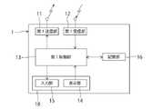
図1は、本発明の一実施形態に係るLED照明システムの構成を概念的に示したブロック図である。図1に示す様に、LED照明システムは、複数のLED照明装置2と、これらのLED照明装置2を無線通信により制御する照明制御装置1と、有線式のネットワーク3と、センサ4とを備えている。[1] Configuration of LED lighting system FIG. 1 is a block diagram conceptually showing the configuration of an LED lighting system according to an embodiment of the present invention. As shown in FIG. 1, the LED lighting system includes a plurality of
ネットワーク3は、ハブ(HUB)を通じて互いに有線接続された複数のゲートウェイGWを有している。ゲートウェイGWの各々は、無線通信により、LED照明装置2及び照明制御装置1との間で情報を伝達し合う。そして、照明制御装置1は、ネットワーク3内の少なくとも1つのゲートウェイGWを介して、LED照明装置2との通信を行う。ゲートウェイGWは、通信プロトコルの変換を行う通信中継器と、照明制御装置1から出力される制御信号に応じてLED照明装置2の照明制御を行う制御器とを有している。 A
本実施形態のLED照明システムによれば、照明制御装置1と複数のLED照明装置2との無線通信が、ネットワーク3(ゲートウェイGW)で中継される。従って、オフィス等の広い空間に複数のLED照明装置2が設置されている場合でも、照明制御装置1とLED照明装置2との間での無線通信を確実に行うことが可能となる。 According to the LED lighting system of this embodiment, wireless communication between the
更に、本実施形態のLED照明システムにおいては、複数のゲートウェイGWが有線接続されている。従って、複数の部屋や複数の階に亘って複数のLED照明装置2が設置されている場合でも、各部屋又は各階にゲートウェイGWが設置されることにより、全てのLED照明装置2の照明制御を、1つの照明制御装置1で一括して管理することが可能になる。 Furthermore, in the LED lighting system of this embodiment, a plurality of gateways GW are wired. Therefore, even when a plurality of
センサ4は、照度センサと人感センサとが一体的に形成されたものであり、複数のLED照明装置2が配置されている空間に設けられている。センサ4は、無線通信により、ゲートウェイGWとの間で情報を伝達し合う。そして、照明制御装置1は、ネットワーク3を通じて、センサ4から出力された検出信号を取得する。尚、LED照明装置2が配置されている空間には、照明センサと人感センサとが別個に設けられていてもよい。 The
図2は、照明制御装置1の構成を概念的に示したブロック図である。図2に示す様に、照明制御装置1は、第1送信部11と、第1受信部12と、第1制御部13と、表示部14と、入力部15と、記憶部16とを有している。本実施形態において、表示部14及び入力部15は、これらが一体的に形成されたタッチパネル18である。 FIG. 2 is a block diagram conceptually showing the configuration of the
第1送信部11は、第1制御部13によって生成された信号を、ネットワーク3を通じてLED照明装置2やセンサ4へ送信する。第1制御部13が生成する信号には、点灯信号、消灯信号、及び調光信号の少なくとも何れか1つの信号を持った制御信号が含まれる。第1受信部12は、LED照明装置2やセンサ4から出力された信号を、ネットワーク3を通じて受信する。尚、第1制御部13が実行する制御の詳細については、後述する。 The
図3は、LED照明装置2の各々が持つ構成を概念的に示したブロック図である。図3に示す様に、LED照明装置2は、第2送信部21と、第2受信部22と、第2制御部23と、LED24とを有している。又、LED照明装置2は、他のLED照明装置2との識別を可能にする第1識別情報ILEDを有している。FIG. 3 is a block diagram conceptually showing the configuration of each of the
第2送信部21は、第2制御部23によって生成された信号を、ネットワーク3を通じて照明制御装置1へ送信する。第2制御部23が生成する信号には、第1識別情報ILEDを持った情報信号が含まれる。本実施形態において、第2送信部21及び第2受信部22は、これらが一体的に形成されたワイヤレスモジュールであり、第1識別情報ILEDは、そのワイヤレスモジュールを、他のLED照明装置2に設けられたワイヤレスモジュールと識別するためのものである。第2送信部21からの信号の送信は、例えば、照明制御装置1からの指令に応じて実行される。The
第2受信部22は、照明制御装置1から出力された制御信号、又はこの制御信号に応じてゲートウェイGWの制御器から出力される制御信号を、ネットワーク3を通じて受信する。第2制御部23は、第2受信部22にて受信される制御信号に基づいて、LED24の照明制御(点灯、消灯、調光等)を行う。 The
[2]LED照明システムの制御
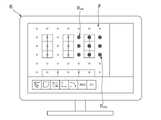
図4は、照明制御装置1の第1制御部13が実行する制御及びユーザが行う操作を示したフローチャートである。先ず、ステップS20において、ユーザが、パーソナルコンピュータ(以下、「PC」と称す。)を用いて事前準備を行う。図5~12は、この事前準備に関連する画面が表示されたPCモニタ6の平面図である。[2] Control of LED Lighting System FIG. 4 is a flowchart showing the control performed by the
ステップS20では、ユーザは先ず、複数のLED照明装置2の配置が示された配灯画像PをPCのハードディスクに読み込み、読み込んだ配灯画像PをPCモニタ6に表示する(図5参照)。図5では、LED照明装置2の配置が複数の丸印によって示されている。尚、配灯画像Pには、内装や設備等に関する画像が含まれていてもよい。又、配灯画像Pは、透視図法により作成された画像であってもよい。更に、ユーザは、配灯画像Pを生成するために必要な、複数のLED照明装置2の配置に関する配置情報を、PCのハードディスクに読み込んでもよい。この場合、ユーザは、PCに、ハードディスクから配置情報を読み出させると共に、その配置情報に基づいて配灯画像Pを生成させる。 In step S20, the user first reads the light distribution image P showing the arrangement of the plurality of
配灯画像Pが表示された画面において、ユーザは、PCモニタ6に表示された配灯画像P上に、マウス等の操作により象徴画像を作成又は配置する(ステップS20)。ここで、象徴画像は、少なくとも1つの第1識別情報ILEDが関連付けられることにより、その第1識別情報ILEDを持つLED照明装置2と対応付けられることになる画像である。本実施形態において、象徴画像は、PCモニタ6や照明制御装置1において配灯画像Pに重ねて表示されることにより、配灯画像P上において象徴画像と重なる位置に配された少なくとも1つのLED照明装置2に対応していることを、ユーザに認識させることが出来る。即ち、配灯画像P上において、象徴画像は、その象徴画像と重なる位置に配された少なくとも1つのLED照明装置2に対応していることを象徴する画像である。尚、象徴画像は、少なくとも1つの第1識別情報ILEDが関連付けられる箱の様なものとして、配灯画像Pを表示させずに作成されてもよい。On the screen displaying the light arrangement image P, the user creates or places a symbolic image on the light arrangement image P displayed on the
象徴画像には、配灯画像P上において、同じ照明制御が実行されるLED照明装置2のエリアを表し、そのエリア内の複数のLED照明装置2と対応付けられることになる画像(図7参照)が含まれる。以下では、この画像を「エリア画像」と称す。更に、象徴画像には、1つのLED照明装置2とだけ対応付けられることになる画像(図12参照)が含まれる。以下では、特に断らない限り、この画像に対して「象徴画像」という用語を用いる。 The symbolic image represents an area of the
図5に示す様に、配灯画像Pが表示された画面には、配灯画像Pに加えて、ボタンB1~B7及びEG1~EG10が表示される。ボタンB1は、ユーザが象徴画像の配置操作を行うための配置操作画面(図9参照)をPCモニタ6に表示させるボタンである。ボタンB2は、ユーザがエリア画像の作成操作を行うための作成操作画面(図5参照)をPCモニタ6に表示させるボタンである。ボタンB6は、PCモニタ6に表示されている画面に移る前の画面を再びPCモニタ6に表示させるボタンである。ボタンB7は、象徴画像の配置操作やエリア画像の作成操作を完了させるためのボタンである。 As shown in FIG. 5, on the screen displaying the lighting image P, in addition to the lighting image P, buttons B1 to B7 and EG1 to EG10 are displayed. The button B1 is a button for displaying on the PC monitor 6 a layout operation screen (see FIG. 9) for the user to perform a layout operation of symbolic images. The button B2 is a button for displaying on the PC monitor 6 a creation operation screen (see FIG. 5) for the user to create an area image. The button B6 is a button for redisplaying on the
作成操作画面(図5参照)において、ボタンB3~B5は、ユーザがエリア画像を作成する際に選択されるボタンである。ここで、ボタンB3は、長方形のエリア画像を作成する際に選択される(図6参照)。具体的には、ユーザは、マウス等の操作により、ボタンB3を選択した後、PCモニタ6に表示された画面において互いに異なる2つの位置を指定する。これにより、その2つの位置を結んだ直線を対角線とする長方形のエリア画像が作成される。ボタンB4は、長方形に限定されない様々な形状を持ったエリア画像について、そのエリア画像の外縁のうち直線部分を作成する際に選択される。具体的には、ユーザは、マウス等の操作により、ボタンB4を選択した後、PCモニタ6に表示された画面において複数の位置を指定する。これにより、その複数の位置が指定順に結ばれた線画像が作成される。ボタンB5は、エリア画像の外縁のうち円弧状の曲線部分を作成する際に選択される。具体的には、ユーザは、マウス等の操作により、ボタンB5を選択した後、PCモニタ6に表示された画面において1つの位置を指定する。次に、別の位置を指定した後、その位置を、先に指定した位置を中心としてスライドさせる。これにより、先に指定された位置を中心とする円弧状の曲線画像が作成される。 On the creation operation screen (see FIG. 5), buttons B3 to B5 are buttons selected when the user creates an area image. Here, button B3 is selected when creating a rectangular area image (see FIG. 6). Specifically, the user designates two different positions on the screen displayed on the
ユーザは、作成操作画面において上述した作成操作を行うことにより、配灯画像P上にエリア画像を作成することが出来る。図7には、配灯画像P上に4つのエリア画像PAREA(1)~PAREA(4)が作成され、配灯画像Pに示された全てのLED照明装置2に、4つのエリア画像PAREA(1)~PAREA(4)の何れかが対応している場合が示されている。尚、配灯画像Pに示されたLED照明装置2のうち、照明制御装置1により制御せんとする幾つかのLED照明装置2にのみ、エリア画像を対応させてもよい。或いは、照明制御装置1により制御せんとする幾つかのLED照明装置2に、エリア画像を対応させ、残りのLED照明装置2には、後述する配置操作により象徴画像を対応させてもよい。The user can create an area image on the light distribution image P by performing the creation operation described above on the creation operation screen. In FIG. 7, four area images PAREA (1) to PAREA (4) are created on the light distribution image P, and four area images P AREA (1) to P AREA (4) are created on all the
エリア画像の作成操作は、上述した操作に限られるものではない。例えば、PCモニタ6に様々な形状を持った図形が表示され、ユーザが、マウス等の操作により、PCモニタ6に表示されている複数の図形から幾つかの図形を選択すると共に、選択した図形を組み合わせて1つのエリア画像を作成してもよい。又、エリア画像の作成操作は、PCに限らず、照明制御装置1にて行われてもよい。 The area image creation operation is not limited to the operation described above. For example, figures having various shapes are displayed on the
図5に示された画面において、ユーザによるマウス等の操作によりボタンB1が選択された場合、象徴画像の配置操作を行うための画面が表示される(図9参照)。このとき、PCモニタ6には、ボタンB3~B5に代えてボタンB11~B14が表示される。これにより、図9に示す様に、PCモニタ6には、配灯画像Pと、ボタンB1、B2、B11~B14、B6、及びB7とが表示される。 In the screen shown in FIG. 5, when the button B1 is selected by the user's operation of the mouse or the like, a screen for arranging the symbolic image is displayed (see FIG. 9). At this time, buttons B11 to B14 are displayed on the
配置操作画面(図9参照)において、ボタンB11~B13は、ユーザが象徴画像を配置する際に選択されるボタンである。又、ボタンB14は、配置された象徴画像をユーザが消去する際に選択されるボタンである。 On the placement operation screen (see FIG. 9), buttons B11 to B13 are buttons selected when the user places symbolic images. A button B14 is a button selected when the user deletes the arranged symbolic image.
ボタンB11は、象徴画像を1つだけ配置する際に選択される。具体的には、ユーザは、マウス等の操作により、ボタンB11を選択した後、PCモニタ6に表示された画面において1つの位置を指定する。位置の指定が完了すると、PCモニタ6には、象徴画像の種類を選択するための選択画面が表示される(図10参照)。そして、ユーザは、マウス等の操作により、選択画面において象徴画像の種類を選択する。これにより、指定された位置に、選択された種類の象徴画像が配置される。 The button B11 is selected when arranging only one symbolic image. Specifically, the user designates one position on the screen displayed on the
ボタンB12は、同じ種類の複数の象徴画像を一列に配置する際に選択される。具体的には、ユーザは、マウス等の操作により、ボタンB12を選択した後、PCモニタ6に表示された画面において2つの位置を指定する。2つの位置の指定が完了すると、PCモニタ6には、象徴画像の種類を選択するための選択画面が表示される(図10参照)。そして、ユーザは、マウス等の操作により、選択画面において象徴画像の種類を選択する。象徴画像の種類の選択が完了すると、PCモニタ6には、象徴画像の配置数を入力するための入力画面が表示される(図11参照)。そして、ユーザは、マウスやキーボード等の操作により、入力画面において数値を入力する。これにより、指定された2つの位置を結んだ直線上に、入力された数の象徴画像が等間隔で配置される。 The button B12 is selected when arranging a plurality of symbolic images of the same type in a line. Specifically, the user designates two positions on the screen displayed on the
ボタンB13は、同じ種類の複数の象徴画像をマトリックス状に配置する際に選択される。具体的には、ユーザによるマウス等の操作によりボタンB13が選択されると、PCモニタ6には、ボタンB11~B14に代えてボタンB3~B5が表示される(図10参照)。そして、ユーザは、マウス等の操作により、ボタンB3を選択した後、図10に示す様に、PCモニタ6に表示された画面において互いに異なる2つの位置を指定する。これにより、その2つの位置を結んだ直線を対角線とする長方形の領域Rが指定される。2つの位置の指定が完了すると、PCモニタ6には、象徴画像の種類を選択するための選択画面が表示される(図10参照)。そして、ユーザは、マウス等の操作により、選択画面において象徴画像の種類を選択する。象徴画像の種類の選択が完了すると、PCモニタ6には、象徴画像の配置数(行数及び列数)を入力するための入力画面が表示される(図11参照)。そして、ユーザは、マウスやキーボード等の操作により、入力画面において数値を入力する。これにより、指定された長方形の領域上に、入力された数の象徴画像がマトリックス状に配置される(図12参照)。 The button B13 is selected when arranging a plurality of symbolic images of the same type in a matrix. Specifically, when the user selects the button B13 by operating the mouse or the like, the buttons B3 to B5 are displayed on the
ユーザは、配置操作画面において上述した配置操作を行うことにより、配灯画像P上に象徴画像を配置することが出来る。図12には、配灯画像P上に同じ種類の9つの象徴画像PSMBLを配置した場合が示されている。この様な配置操作を繰り返し実行することにより、配灯画像Pに示された全てのLED照明装置2に、象徴画像を対応させることが出来る。尚、配灯画像Pに示されたLED照明装置2のうち、照明制御装置1により制御せんとする幾つかのLED照明装置2にのみ、象徴画像を対応させてもよい。或いは、照明制御装置1により制御せんとする幾つかのLED照明装置2に、象徴画像を対応させ、残りのLED照明装置2には、上述した作成操作によりエリア画像を対応させてもよい。更には、象徴画像は、エリア画像によって表されるエリア内に配置されてもよい。又、象徴画像の配置操作は、PCに限らず、照明制御装置1にて行われてもよい。The user can arrange the symbolic image on the light distribution image P by performing the above-described arrangement operation on the arrangement operation screen. FIG. 12 shows a case where nine symbolic images PSMBL of the same type are arranged on the light distribution image P. As shown in FIG. By repeatedly performing such an arrangement operation, all the
ステップS20において、ユーザによりエリア画像PAREA(1)~PAREA(4)が作成された場合、作成されたエリア画像PAREA(1)~PAREA(4)はPCのハードディスクに記憶される。このとき、エリア画像PAREA(1)~PAREA(4)は、各々がボタンEG1~EG10の何れかと1対1対応で関連付けられてハードディスクに記憶されることにより、リスト化されてもよい。エリア画像PAREA(1)~PAREA(4)とボタンEG1~EG10との関連付けは、例えば、これらがPCモニタ6に表示されている画面において、マウス等を用いたユーザによるドラッグ操作により行われる(図8参照)。In step S20, when the user creates the area images PAREA (1) to PAREA (4), the created area images PAREA (1) to PAREA (4) are stored in the hard disk of the PC. At this time, the area images PAREA (1) to PAREA (4) may be listed by being associated with one of the buttons EG1 to EG10 in a one-to-one correspondence and stored in the hard disk. The area images PAREA (1) to PAREA (4) and the buttons EG1 to EG10 are associated with each other by, for example, a drag operation by the user using a mouse or the like on the screen where these are displayed on the
又、ステップS20において、ユーザにより象徴画像PSMBLが配置された場合、配置された象徴画像PSMBLはPCのハードディスクに記憶される。Also, in step S20, when the symbolic image PSMBL is arranged by the user, the arranged symbolic image PSMBL is stored in the hard disk of the PC.
事前準備が完了すると、ステップS21において、ユーザは、PCのハードディスクに記憶されている、配灯画像P、エリア画像PAREA(1)~PAREA(4)、及び象徴画像PSMBLを、例えばネットワーク3を介して、照明制御装置1に転送する。When the advance preparation is completed, in step S21, the user transmits the light distribution image P, the area images PAREA (1) to PAREA (4), and the symbol image PSMBL stored in the hard disk of the PC to, for example, a
これにより、ステップS11において、照明制御装置1の第1制御部13は、第1受信部12を通じて、配灯画像P、エリア画像PAREA(1)~PAREA(4)、及び象徴画像PSMBLを読み込むと共に、これらの画像を記憶部16に記憶させる。Accordingly, in step S11, the
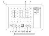
次に、ステップS12において、第1制御部13は、記憶部16から配灯画像Pを読み出すと共に、読み出した配灯画像Pをタッチパネル18に表示させる。又、第1制御部13は、記憶部16からエリア画像PAREA(1)~PAREA(4)及び象徴画像PSMBLの少なくとも何れか一方を読み出すと共に、読み出した画像を配灯画像Pに重ねてタッチパネル18に表示させる。図13は、エリア画像及び象徴画像のうち、エリア画像PAREA(1)~PAREA(4)のみがタッチパネル18に表示されている照明制御装置1の平面図である。又、図14は、エリア画像PAREA(1)~PAREA(4)及び象徴画像PSMBLの何れもがタッチパネル18に表示されている照明制御装置1の平面図である。尚、ステップS12では、第1制御部13は、タッチパネル18に、配灯画像Pは表示させずに、エリア画像PAREA(1)~PAREA(4)及び象徴画像PSMBLの少なくとも何れか一方のみを表示させてもよい。又、象徴画像が、少なくとも1つの第1識別情報ILEDが関連付けられる箱の様なものである場合、その象徴画像のみがタッチパネル18に表示されてもよい。Next, in step S<b>12 , the
次に、ステップS13において、第1制御部13は、第1識別情報ILEDを含んだ情報信号を第1受信部12に受信させることにより、ネットワーク3を通じて、複数のLED照明装置2から第1識別情報ILEDを取得する。そして、第1制御部13は、取得した第1識別情報ILEDをタッチパネル18に表示させる(図13及び図14参照)。このとき、第1制御部13は、取得した第1識別情報ILEDの各々について、その第1識別情報ILEDを持ったLED照明装置2を点灯させるための点灯信号を発生させる第1スイッチS1を生成する。そして、第1制御部13は、生成した第1スイッチS1を、第1識別情報ILEDに対応させてタッチパネル18に表示させる。本実施形態では、第1スイッチS1は、第1識別情報ILEDに重ねて表示されている。尚、第1スイッチS1は、点灯信号及び消灯信号を選択的に発生させるものであってもよい。又、第1スイッチS1は、記憶部16に記憶されていてもよく、第1制御部13は、取得した第1識別情報ILEDの各々に対応する第1スイッチS1を記憶部16から読み出すと共に、読み出した第1スイッチS1をタッチパネル18に表示させてもよい。Next, in step S13, the
次に、ユーザは、LED照明装置2と、タッチパネル18に表示されたエリア画像PAREA(1)~PAREA(4)又は象徴画像PSMBLとを互いに関連付ける(ステップS22)。具体的には、第1識別情報ILED及び第1スイッチS1が表示された画面において、ユーザは、タッチパネル18上で第1スイッチS1を操作することにより、LED照明装置2を点灯させる。この様にして、ユーザは、操作した第1スイッチS1に対応するLED照明装置2の実際の位置を確認する。その後、ユーザは、操作した第1スイッチS1に重なって表示されている第1識別情報ILEDを、確認した実際の位置に基づいて、配灯画像P上の対応する位置に表示されているエリア画像PAREA(1)~PAREA(4)又は象徴画像PSMBLと重なる位置にドラッグする。Next, the user associates the
上述したユーザのドラッグ操作が実行されたとき、ステップS14において、第1制御部13は、ドラッグされた第1識別情報ILEDを、その第1識別情報ILEDが重ねられたエリア画像又は象徴画像に関連付けて記憶部16に記憶させる。図13に示す様に、第1識別情報ILEDがエリア画像PAREA(1)に関連付けられる場合、ユーザのドラッグ操作とステップS14での第1制御部13の制御とにより、エリア画像PAREA(1)で表されるエリア内の全てのLED照明装置2の第1識別情報ILEDが、エリア画像PAREA(1)に関連付けて記憶部16に記憶される。When the above-described user's drag operation is performed, in step S14, the
尚、図14に示す様に、エリア画像PAREA(1)によって表されるエリア内に象徴画像PSMBLが配置されている場合において、第1識別情報ILEDが、象徴画像PSMBLと重なる位置にドラッグされたとき、第1制御部13は、ドラッグされた第1識別情報ILEDを、象徴画像PSMBLにのみ関連付けて記憶部16に記憶させてもよいし、エリア画像PAREA(1)及び象徴画像PSMBLの何れとも関連付けて記憶部16に記憶させてもよい。As shown in FIG. 14, in the case where the symbolic image PSMBL is arranged in the area represented by the area image PAREA (1), the first identification information ILED overlaps the symbolic image PSMBL . , the
この様なLED照明装置2の位置確認に基づくユーザのドラッグ操作(ステップS22)と、第1制御部13の制御(ステップS14)とによれば、第1識別情報ILEDが、エリア画像PAREA(1)~PAREA(4)又は象徴画像PSMBLに対して正確に関連付けられる。According to the user's drag operation (step S22) based on such position confirmation of the
次に、ステップS15において、第1制御部13は、エリア画像に関連付けて、そのエリア画像に対応する複数のLED照明装置2の制御に関する照明制御情報を、記憶部16に記憶させる。又、第1制御部13は、象徴画像に関連付けて、その象徴画像に対応する1つのLED照明装置2の制御に関する照明制御情報を、記憶部16に記憶させる。尚、照明制御情報は、ユーザによるタッチパネル18の操作により入力される(ステップS23)。又、照明制御情報には、照度やタイムスケジュール等の情報が含まれる。 Next, in step S<b>15 , the
ステップS11~S15の第1制御部13の制御、及びステップS21~S23のユーザの操作によれば、タッチパネル18の簡単な操作により、所望のエリア内で全てのLED照明装置2に対して同じ照明制御を行うための設定、並びにLED照明装置2に対して個別に照明制御を行うための設定が遂行される。 According to the control of the
設定の完了後、ステップS16において、第1制御部13は、エリア画像に関連付けられた第1識別情報ILED及び照明制御情報に基づいて、制御信号を生成する。そして、第1制御部13は、生成した制御信号を、第1送信部11を通じて、エリア画像で表されるエリア内の全てのLED照明装置2に送信する。これにより、所望のエリア内で、全てのLED照明装置2に対して同じ照明制御が実行される。After completing the setting, in step S16, the
又、第1制御部13は、象徴画像に関連付けられた第1識別情報ILED及び照明制御情報に基づいて、制御信号を生成する。そして、第1制御部13は、生成した制御信号を、第1送信部11を通じて、象徴画像に対応するLED照明装置2に送信する。これにより、LED照明装置2に対して個別に照明制御が実行される。Also, the
尚、ステップS16では、第1制御部13は、第1識別情報ILED及び照明制御情報に加えて、センサ4から出力される検出信号にも基づいて、制御信号を生成してもよい。In step S16, the
本実施形態の照明制御装置1によれば、ユーザによるタッチパネル18の簡単な操作により、照明制御情報に対して、少なくとも1つの第1識別情報ILEDが、エリア画像PAREA(1)~PAREA(4)又は象徴画像PSMBLを介して関連付けられる。従って、複数のLED照明装置2を、照明制御情報との所望の関連態様で制御することが可能になる。ここで、所望の関連態様には、LED照明装置2の各々に照明制御情報が関連付けられた態様、LED照明装置2のグループに照明制御情報が関連付けられた態様、及びこれらを組み合わせた態様が含まれる。この様に、本実施形態の照明制御装置1によれば、複数のLED照明装置2を個別に制御すると共に、それらの制御を1つの照明制御装置1で一括して管理することが可能になる。又、本実施形態の照明制御装置1においては、エリア画像や象徴画像の変更等、照明制御に関する設定の変更が容易である。更には、複数のLED照明装置2が無線通信により制御されるため、有線式のシステムで構築されていた回路(配線)が不要となる。According to the
尚、照明制御装置1によるLED照明装置2の一括管理が可能であることを利用して、例えば、LED照明装置2のそれぞれの使用時間を、照明制御装置1に一括して管理させてもよい。一例として、LED照明装置2にそれぞれ設けられたタイマを、照明制御装置1に一括して管理させる。尚、タイマは、通常、ワイヤレスモジュールに設けられている。 By utilizing the fact that the
蛍光灯などの照明装置の場合、点灯不能になることで、ユーザは、その照明装置の寿命を認識することが出来る。しかし、LED照明装置2は、半永久的な使用が可能であり、機能が徐々に低下するものである。このため、ユーザにとっては、その寿命(照度不足の状態)を認識することが困難である。 In the case of a lighting device such as a fluorescent lamp, the user can recognize the end of the life of the lighting device by not being able to turn on the lighting device. However, the
そこで、照明制御装置1によるLED照明装置2の一括管理が可能であることを利用して、LED照明装置2が寿命(照度不足の状態)に達した場合、その寿命を、例えば照明制御装置1のタッチパネル18に表示させてもよい。これにより、ユーザは、LED照明装置2の寿命を認識することが出来る。 Therefore, by utilizing the fact that the
[3]LED照明システムに関する変形例
LED照明システムに関する2つの変形例(第1変形例及び第2変形例)について説明する。[3] Modifications Regarding LED Lighting System Two modifications (first modification and second modification) regarding the LED lighting system will be described.
[3-1]第1変形例
LED照明システムの第1変形例では、上記実施形態の構成に加えて、LED照明装置2の各々に、第1識別情報ILEDに対応するQRコード(登録商標)が設けられ、記憶部16には、第1識別情報ILEDとQRコード(登録商標)との対応関係を表すテーブルが記憶されている。又、図15に示す様に、照明制御装置1は、QRコード(登録商標)を読み込むQRコード(登録商標)リーダである読込み部17を更に有している。[3-1] First Modification In the first modification of the LED lighting system, in addition to the configuration of the above embodiment, each of the
この様なLED照明システムでは、上述したステップS13において、第1制御部13は、テーブルに基づいて、読込み部17により読み込まれたQRコード(登録商標)に対応する第1識別情報ILEDを取得する。そして、第1制御部13は、取得した第1識別情報ILEDをタッチパネル18に表示させる。読込み部17によるQRコード(登録商標)の読込みは、例えば、LED照明装置2を設置する段階で、その設置前にユーザにより実行される。In such an LED lighting system, in step S13 described above, the
LED照明システムの第1変形例によれば、このLED照明システムが、例えば隣接する複数の店舗の各々に採用された場合でも、照明制御装置1の各々のタッチパネル18には、この照明制御装置1と共に同じLED照明システムを構成しているLED照明装置2が持つ第1識別情報ILEDのみが表示されることになる。よって、ユーザであるシステム管理者が、自身が所有するLED照明システムとは別のLED照明システムから第1識別情報ILEDを取得し、その第1識別情報ILEDをエリア画像や象徴画像に誤って関連付けてしまうといった不具合が、LED照明システムの第1変形例によれば防止される。According to the first modified example of the LED lighting system, even if this LED lighting system is adopted in each of a plurality of adjacent stores, for example, the
[3-2]第2変形例
LED照明システムの第2変形例では、上記実施形態の構成に加えて、ゲートウェイGWが、それぞれの識別を可能にする第2識別情報IGWを持っている。又、図16に示す様に、ゲートウェイGWの各々には、外部に光を放つ発光部5が設けられている。発光部5として、例えばLEDが用いられる。[3-2] Second Modification In the second modification of the LED lighting system, in addition to the configuration of the above embodiment, the gatewayGW has second identification information IGW that enables identification of each. Further, as shown in FIG. 16, each gateway GW is provided with a
図17は、LED照明システムの第2変形例について、照明制御装置1の第1制御部13が実行する制御及びユーザが行う操作を示したフローチャートである。又、図18は、タッチパネル18に第2識別情報IGWが表示された照明制御装置1の平面図である。図17に示す様に、第1制御部13は、図4に示される制御に加えて、ステップS13の制御の前にステップS17の制御を実行する。ステップS17では、第1制御部13は、照明制御装置1との無線通信が可能な範囲に存在するゲートウェイGWの第2識別情報IGWを取得する。そして、第1制御部13は、取得した第2識別情報IGWをタッチパネル18に表示させる(図18参照)。一例として、第2識別情報IGWは、対応するゲートウェイGWと照明制御装置1との間の距離が小さい順に、タッチパネル18に表示される。FIG. 17 is a flowchart showing the control performed by the
このとき、第1制御部13は、取得した第2識別情報IGWの各々について、その第2識別情報IGWを持ったゲートウェイGWの発光部5を点灯させるための点灯信号を発生させる第2スイッチS2を生成する。そして、第1制御部13は、生成した第2スイッチS2を、第2識別情報IGWに対応させてタッチパネル18に表示させる。本実施形態では、第2スイッチS2は、第2識別情報IGWに重ねて表示されている。尚、第2スイッチS2は、点灯信号及び消灯信号を選択的に発生させるものであってもよい。又、第2スイッチS2は、記憶部16に記憶されていてもよく、第1制御部13は、取得した第2識別情報IGWの各々に対応する第2スイッチS2を記憶部16から読み出すと共に、読み出した第2スイッチS2をタッチパネル18に表示させてもよい。At this time, the
次に、ユーザは、ゲートウェイGWを選定する(ステップS24)。具体的には、第2識別情報IGW及び第2スイッチS2が表示された画面において、ユーザは、タッチパネル18上で第2スイッチS2を操作することにより、ゲートウェイGWの発光部5を点灯させる。この様にして、ユーザは、操作した第2スイッチS2に対応するゲートウェイGWの実際の位置を確認する。そして、ユーザは、照明制御装置1との無線通信が可能な範囲に存在するゲートウェイGWの中から、ゲートウェイGWを1つ選定する。Next, the user selects a gateway GW (step S24). Specifically, on the screen on which the second identification informationIGW and the second switch S2 are displayed, the user operates the second switch S2 on the
ゲートウェイGWが選定されると、ステップS13において、第1制御部13は、選定されたゲートウェイGWを通じて、このゲートウェイGWとの直接的な無線通信が可能なLED照明装置2が持つ第1識別情報ILEDを取得する。そして、第1制御部13は、取得した第1識別情報ILEDをタッチパネル18に表示させる。以降、上記実施形態と同様の制御が実行される。When the gateway GW is selected, in step S13, the
LED照明システムの第2変形例によれば、選択されたゲートウェイGWとの直接的な無線通信が可能な範囲に存在するLED照明装置2の第1識別情報ILEDのみが、タッチパネル18に表示される。よって、ドラッグ操作による第1識別情報ILEDとエリア画像又は象徴画像との関連付けが容易になる。According to the second modification of the LED lighting system, only the first identification information ILED of the
又、ユーザは、第2スイッチS2の操作により、ゲートウェイGWを点灯させてゲートウェイGWの実際の位置を確認することが出来る。従って、ユーザは、ゲートウェイGWの選定(ステップS24)と、第1識別情報ILEDとエリア画像又は象徴画像との関連付け(ステップS22)とを、選定するゲートウェイGWを変更しながら繰り返し実行することにより、設置されている全てのLED照明装置2についての第1識別情報ILEDとエリア画像又は象徴画像との関連付けを、容易に行うことが出来る。Also, the user can confirm the actual position of the gateway GW by turning on the gateway GW by operating the second switch S2. Therefore, the user repeatedly selects the gateway GW (step S24) and associates the first identification information ILED with the area image or the symbolic image (step S22) while changing the selected gateway GW. , it is possible to easily associate the first identification information ILED for all the installed
[4]LED照明システムに対するデマンド制御
次に、デマンド制御について説明する。ここで、デマンド制御とは、オフィスや店舗等で使用される総電力量を監視し、その総電力量が所定の閾値を超えない様に、負荷(照明装置や空調機など)で消費される電力量(以下、「電力消費量」と称す。)を制御することである。そして、本実施形態では、デマンド制御を実現するためのデマンド制御システムが構築されている。このデマンド制御システムでは、使用される総電力量が監視され、その総電力量が所定の閾値を超えない様に、LED照明システムや空調システムなどに含まれる負荷の電力消費量が制御される。以下では、主にLED照明システムに対してデマンド制御を実行する場合について説明する。[4] Demand Control for LED Lighting System Next, demand control will be described. Here, demand control refers to monitoring the total amount of power used in offices, stores, etc., and controlling the amount of power consumed by loads (lighting equipment, air conditioners, etc.) so that the total power does not exceed a predetermined threshold It is to control the amount of power (hereinafter referred to as "power consumption"). In addition, in this embodiment, a demand control system for realizing demand control is constructed. In this demand control system, the total power consumption is monitored, and the power consumption of loads included in LED lighting systems, air conditioning systems, etc. is controlled so that the total power consumption does not exceed a predetermined threshold. Below, the case where demand control is mainly performed with respect to an LED lighting system is demonstrated.
[4-1]デマンド制御システム
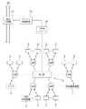
図19は、LED照明システムを含むデマンド制御システムの構成を概念的に示したブロック図である。図19に示す様に、デマンド制御システムは、電力線70に接続された電力計測器71と、デマンド制御装置72と、接点コンバータ73とを含んでいる。図19では図示されていないが、電力線70には、LED照明システムに含まれるLED照明装置2やセンサ4などが接続されている。尚、電力線70には、空調システムに含まれる空調機など、他の負荷が接続されていてもよい。[4-1] Demand Control System FIG. 19 is a block diagram conceptually showing the configuration of a demand control system including an LED lighting system. As shown in FIG. 19, the demand control system includes a
電力計測器71は、使用される総電力量を計測する。電力計測器71は、デマンド制御装置72に接続されており、デマンド制御装置72は、電力計測器71による計測結果(総電力量)に基づいて、デマンド制御を実行するか否かを判断する。具体的には、デマンド制御装置72は、計測された総電力量が、予め設定されている所定の閾値を超えたか否かを判定する。総電力量が所定の閾値を超えていると判定された場合、デマンド制御装置72は、デマンド制御を実行するためのデマンド制御信号を出力する。本実施形態において、デマンド制御信号は、リレー接点等の実接点を用いて出力される接点信号、又はトランジスタ等を用いて出力される無接点信号である。一方、総電力量が所定の閾値を超えていないと判定された場合、デマンド制御装置72は、デマンド制御信号を出力せずに待機する。 A
デマンド制御装置72は、接点コンバータ73を介して、LED照明システムを構成するネットワーク3に接続されている。図19には、特に、ハブ(HUB)にデマンド制御装置72が接続された形態が示されている。デマンド制御装置72から出力されたデマンド制御信号は、接点コンバータ73に入力される。接点コンバータ73は、入力されたデマンド制御信号を、デジタル信号に変換する。このデジタル信号は、ハブ(HUB)を介してネットワーク3内のゲートウェイGWに送信される。或いは、デジタル信号は、ネットワーク3を通じてLED照明装置2に送信される。 The
ゲートウェイGWの各々が持つ制御器、又はLED照明装置2の各々が持つ第2制御部23には、これらがデジタル信号を受信したときにLED照明装置2のLED24に対して実行する照明制御に関する情報が予め設定されている。具体的には、このときの照明制御に関する情報として、LED照明装置2での電力消費量を低下させることを目的としたものが採用される。照明制御の一例として、LED照明装置2の全ての照度を、一様に、予め設定された所定の照度まで低下させる制御が挙げられる。照明制御の他の例として、LED照明装置2の照度を、領域ごとに、予め設定された所定の照度まで低下させる制御が挙げられる。 The controller possessed by each gateway GW or the
上記デマンド制御システムによれば、LED照明システムに対してデマンド制御を実行することにより、電力の過剰な消費を抑制することが出来る。ここで、重要な点は、本実施形態のLED照明システムが、複数のLED照明装置2を個別に制御すると共にそれらの制御を一括して管理することが出来るものであり、この様なLED照明システムに対してデマンド制御が実行されるという点である。即ち、デマンド制御時に実行されるLED照明装置2の制御(照明制御)を、照明制御装置1やPCなどでの一括管理下で個別に設定することが出来るが故に、デマンド制御時にLED照明システムへ送信するデマンド制御信号には照明制御に関する情報を含ませる必要がなく、従ってデマンド制御信号として、接点信号又は無接点信号を用いることが可能となっている。よって、デマンド制御システムの構築が容易である。 According to the demand control system, excessive power consumption can be suppressed by executing demand control for the LED lighting system. Here, the important point is that the LED lighting system of the present embodiment can individually control a plurality of
[4-2]デマンド制御システムに関する変形例
図20は、デマンド制御システムの第1変形例について、そのデマンド制御システムの構成を概念的に示したブロック図である。図20に示す様に、ネットワーク3を構成する複数のゲートウェイGWのうちの何れか1つが、接点コンバータ73と一体に構成されていてもよい。これにより、デマンド制御システムの構築が簡略化される。[4-2] Modification of Demand Control System FIG. 20 is a block diagram conceptually showing the configuration of the demand control system of the first modification of the demand control system. As shown in FIG. 20 , any one of the plurality of gateways GW that constitute the
図21は、デマンド制御システムの第2変形例について、そのデマンド制御システムの構成を概念的に示したブロック図である。図21に示す様に、デマンド制御システムにおいて、PWM(Pulse Width Modulation)コンバータ74が、接点コンバータ73に代えて設けられていてもよい。この場合、デマンド制御は、以下の様に実行される。 FIG. 21 is a block diagram conceptually showing the configuration of the demand control system of the second modification of the demand control system. As shown in FIG. 21 , a PWM (Pulse Width Modulation)
デマンド制御装置72は、電力計測器71の計測結果(総電力量)に基づいてデマンド制御を実行すると判定したとき、デマンド制御を実行するためのデマンド制御信号として、PWM信号を出力する。デマンド制御装置72から出力されたデマンド制御信号は、PWMコンバータ74に入力される。PWMコンバータ74は、入力されたデマンド制御信号を、デジタル信号に変換する。このデジタル信号は、ハブ(HUB)を介してネットワーク3内のゲートウェイGWに送信される。或いは、デジタル信号は、ネットワーク3を通じてLED照明装置2に送信される。そして、LED照明装置2の第2制御部23は、PWMコンバータ74から出力されるデジタル信号(制御信号)、又はこのデジタル信号に応じてゲートウェイGWの制御器から出力される制御信号に基づいて、LED24の照明制御(点灯、消灯、調光等)を行う。この場合、デマンド制御時の照明制御に関する情報は、デマンド制御装置72側で設定されることになる。尚、デマンド制御システムには、接点コンバータ73及びPWMコンバータ74の何れか一方が設けられた構成に限らず、それらの両方が設けられた構成が採用されてもよい。 When the
図22は、デマンド制御システムの第3変形例について、そのデマンド制御システムの構成を概念的に示したブロック図である。図22に示す様に、ネットワーク3を構成する複数のゲートウェイGWのうちの何れか1つが、PWMコンバータ74と一体に構成されていてもよい。これにより、デマンド制御システムの構築が簡略化される。 FIG. 22 is a block diagram conceptually showing the configuration of the demand control system of the third modification of the demand control system. As shown in FIG. 22 , any one of the plurality of gateways GW that make up the
尚、本発明の各部構成は上記実施形態に限らず、請求の範囲に記載の技術的範囲内で種々の変形が可能である。例えば、上記LED照明システムの各部構成は、LED照明装置に限定されてない様々な照明装置を備えた照明システムに適用することが出来る。 The configuration of each part of the present invention is not limited to the above embodiment, and various modifications are possible within the technical scope described in the claims. For example, the configuration of each part of the LED lighting system described above can be applied to a lighting system including various lighting devices that are not limited to LED lighting devices.
現時点での本発明の好ましい実施態様に関して説明したが、そのような開示を限定的に解釈してはならない。種々の変形および改変は、本発明に属する技術分野における当業者により、上記の開示から間違いなく明らかになるであろう。したがって、添付の請求の範囲は、本発明の真の精神および範囲から逸脱することなく、すべての変形及び改変を包含する、と解釈されるべきものである。 While described in terms of the presently preferred embodiments of the invention, such disclosure should not be construed as limiting. Various alterations and modifications will no doubt become apparent from the above disclosure to those skilled in the art to which the invention pertains. Therefore, the appended claims are to be interpreted as covering all variations and modifications without departing from the true spirit and scope of the invention.
1 照明制御装置
11 第1送信部
12 第1受信部
13 第1制御部
14 表示部
15 入力部
16 記憶部
17 読込み部
18 タッチパネル
2 LED照明装置
21 第2送信部
22 第2受信部
23 第2制御部
24 LED
3 ネットワーク
4 センサ
5 発光部
6 PCモニタ
70 電力線
71 電力計測器
72 デマンド制御装置
73 接点コンバータ
74 PWMコンバータ
GW ゲートウェイ
ILED 第1識別情報
IGW 第2識別情報
P 配灯画像
PAREA(1)~PAREA(4) エリア画像
PSMBL 象徴画像
B1~B7、B11~B14 ボタン
EG1~EG10 ボタン
R 領域
S1 第1スイッチ
S2 第2スイッチ1
3
Claims (3)
Translated fromJapanese前記照明装置を無線通信により制御するための照明制御情報を送信する照明制御装置と、
を備えた照明システムであって、
前記照明制御装置は、画面が表示される表示部を備え、
ユーザは、前記表示部において、複数の照明装置の配置位置が示された配灯画像を表示させずに、前記第1識別情報が関連付けられる照明装置の象徴画像を作成し、
前記照明制御装置は、前記象徴画像に関連付けられた前記照明制御情報に基づいて、制御信号を送信する
照明システム。a plurality of lighting devices having first identification information and controlled by wireless communication;
a lighting control device that transmits lighting control information for controlling the lighting device by wireless communication;
A lighting system comprising
The lighting control device includes a display unit on which a screen is displayed,
The user creates a symbolic image of the lighting device associated with the first identification information without displaying the lighting arrangement image showing the arrangement positions of the plurality of lighting devices on the display unit,
The lighting system, wherein the lighting control device transmits a control signal based on the lighting control information associated with the symbolic image.
前記照明装置を無線通信により制御するための照明制御情報を送信する照明制御装置と、
を備えた照明システムであって、
前記照明制御装置は、画面が表示される表示部を備え、
ユーザは、前記表示部において、複数の照明装置の配置位置が示された配灯画像を表示させずに、同じ照明制御をする複数の前記照明装置に関連づけられるエリア画像を作成することができ、
前記照明制御装置は、前記エリア画像に関連付けられた前記照明制御情報に基づいて、制御信号を送信する
照明システム。a plurality of lighting devices having first identification information and controlled by wireless communication;
a lighting control device that transmits lighting control information for controlling the lighting device by wireless communication;
A lighting system comprising
The lighting control device includes a display unit on which a screen is displayed,
The user can create an area image associated with the plurality of lighting devices that perform the same lighting control without displaying a light arrangement image showing the arrangement positions of the plurality of lighting devices on the display unit,
The lighting system, wherein the lighting control device transmits a control signal based on the lighting control information associated with the area image.
請求項1又は2記載の照明システム。
照明システム。The user can select display or non-display of the light distribution image on the display unit.
3. A lighting system according to claim 1 or 2.
lighting system.
Priority Applications (1)
| Application Number | Priority Date | Filing Date | Title |
|---|---|---|---|
| JP2023060769AJP7631401B2 (en) | 2013-06-20 | 2023-04-04 | Lighting system and lighting control device |
Applications Claiming Priority (4)
| Application Number | Priority Date | Filing Date | Title |
|---|---|---|---|
| JP2013130016 | 2013-06-20 | ||
| JP2013130016 | 2013-06-20 | ||
| JP2020114321AJP6887047B2 (en) | 2013-06-20 | 2020-07-01 | Lighting system |
| JP2021083043AJP7133682B2 (en) | 2013-06-20 | 2021-05-17 | lighting system |
Related Parent Applications (1)
| Application Number | Title | Priority Date | Filing Date |
|---|---|---|---|
| JP2021083043ADivisionJP7133682B2 (en) | 2013-06-20 | 2021-05-17 | lighting system |
Related Child Applications (1)
| Application Number | Title | Priority Date | Filing Date |
|---|---|---|---|
| JP2023060769ADivisionJP7631401B2 (en) | 2013-06-20 | 2023-04-04 | Lighting system and lighting control device |
Publications (2)
| Publication Number | Publication Date |
|---|---|
| JP2022162167Atrue JP2022162167A (en) | 2022-10-21 |
| JP7258207B2 JP7258207B2 (en) | 2023-04-14 |
Family
ID=52104288
Family Applications (9)
| Application Number | Title | Priority Date | Filing Date |
|---|---|---|---|
| JP2015522563AActiveJP6034967B2 (en) | 2013-06-20 | 2014-06-19 | Lighting control apparatus and lighting system |
| JP2016210147AActiveJP6254242B2 (en) | 2013-06-20 | 2016-10-27 | Lighting system |
| JP2017227394AActiveJP6502465B2 (en) | 2013-06-20 | 2017-11-28 | Lighting system |
| JP2019052084AActiveJP6728432B2 (en) | 2013-06-20 | 2019-03-20 | Lighting system |
| JP2020114321AActiveJP6887047B2 (en) | 2013-06-20 | 2020-07-01 | Lighting system |
| JP2021083043AActiveJP7133682B2 (en) | 2013-06-20 | 2021-05-17 | lighting system |
| JP2021122931AActiveJP7464570B2 (en) | 2013-06-20 | 2021-07-28 | Lighting System |
| JP2022136130AActiveJP7258207B2 (en) | 2013-06-20 | 2022-08-29 | lighting system |
| JP2023060769AActiveJP7631401B2 (en) | 2013-06-20 | 2023-04-04 | Lighting system and lighting control device |
Family Applications Before (7)
| Application Number | Title | Priority Date | Filing Date |
|---|---|---|---|
| JP2015522563AActiveJP6034967B2 (en) | 2013-06-20 | 2014-06-19 | Lighting control apparatus and lighting system |
| JP2016210147AActiveJP6254242B2 (en) | 2013-06-20 | 2016-10-27 | Lighting system |
| JP2017227394AActiveJP6502465B2 (en) | 2013-06-20 | 2017-11-28 | Lighting system |
| JP2019052084AActiveJP6728432B2 (en) | 2013-06-20 | 2019-03-20 | Lighting system |
| JP2020114321AActiveJP6887047B2 (en) | 2013-06-20 | 2020-07-01 | Lighting system |
| JP2021083043AActiveJP7133682B2 (en) | 2013-06-20 | 2021-05-17 | lighting system |
| JP2021122931AActiveJP7464570B2 (en) | 2013-06-20 | 2021-07-28 | Lighting System |
Family Applications After (1)
| Application Number | Title | Priority Date | Filing Date |
|---|---|---|---|
| JP2023060769AActiveJP7631401B2 (en) | 2013-06-20 | 2023-04-04 | Lighting system and lighting control device |
Country Status (4)
| Country | Link |
|---|---|
| JP (9) | JP6034967B2 (en) |
| PH (1) | PH12015502826B1 (en) |
| SG (1) | SG11201510146XA (en) |
| WO (1) | WO2014203537A1 (en) |
Families Citing this family (13)
| Publication number | Priority date | Publication date | Assignee | Title |
|---|---|---|---|---|
| WO2016114331A1 (en)* | 2015-01-15 | 2016-07-21 | 株式会社遠藤照明 | Illumination system, and illumination control device |
| JP6651761B2 (en) | 2015-09-18 | 2020-02-19 | 東芝ライテック株式会社 | Lighting control device, lighting control system and lighting control method |
| JP6614550B2 (en)* | 2015-11-09 | 2019-12-04 | パナソニックIpマネジメント株式会社 | Illumination control system, illumination device, illumination control device, operation terminal, and illumination control method |
| JP2018147880A (en)* | 2017-03-08 | 2018-09-20 | コイズミ照明株式会社 | Signal conversion unit, lighting controller, and lighting system |
| KR20180122199A (en)* | 2017-05-02 | 2018-11-12 | 김성용 | LIGHT DEVICE FOR RELAYING THINGS, IoT SYSTEM INCLUDING THE SAME |
| JP6895648B2 (en) | 2017-05-31 | 2021-06-30 | パナソニックIpマネジメント株式会社 | How to register a device, a program that executes that method, and a device system |
| JP6691523B2 (en)* | 2017-10-04 | 2020-04-28 | 株式会社遠藤照明 | Lighting system |
| JP7016055B2 (en)* | 2018-01-30 | 2022-02-04 | パナソニックIpマネジメント株式会社 | Pairing method and pairing device |
| JP7142101B2 (en)* | 2018-11-27 | 2022-09-26 | 京セラ株式会社 | lighting equipment |
| JP7237038B2 (en)* | 2020-03-26 | 2023-03-10 | 株式会社遠藤照明 | Information setting device and lighting system |
| JP7743457B2 (en)* | 2021-11-05 | 2025-09-24 | 株式会社遠藤照明 | lighting equipment |
| JP2023109476A (en)* | 2022-01-27 | 2023-08-08 | パナソニックIpマネジメント株式会社 | LIGHTING CONTROL SYSTEM, DIMENSION PANEL, LIGHTING CONTROL METHOD, AND PROGRAM |
| JP2024158029A (en)* | 2023-04-27 | 2024-11-08 | 大光電機株式会社 | gateway |
Citations (2)
| Publication number | Priority date | Publication date | Assignee | Title |
|---|---|---|---|---|
| JP2009521090A (en)* | 2005-12-22 | 2009-05-28 | コーニンクレッカ フィリップス エレクトロニクス エヌ ヴィ | User interface and method for controlling a lighting system |
| JP2012104449A (en)* | 2010-11-12 | 2012-05-31 | Toshiba Lighting & Technology Corp | Lighting control system |
Family Cites Families (19)
| Publication number | Priority date | Publication date | Assignee | Title |
|---|---|---|---|---|
| JP2905495B2 (en)* | 1989-04-27 | 1999-06-14 | 三菱電機株式会社 | Load control system |
| JPH11135269A (en)* | 1997-10-31 | 1999-05-21 | Toshiba Lighting & Technology Corp | Remote control device and remote control monitoring device |
| JP2003284161A (en)* | 2002-03-20 | 2003-10-03 | Sanyo Electric Co Ltd | Motion control device |
| US7167777B2 (en)* | 2003-11-04 | 2007-01-23 | Powerweb Technologies | Wireless internet lighting control system |
| JP2005183050A (en)* | 2003-12-16 | 2005-07-07 | Toshiba Lighting & Technology Corp | Light control system |
| CN101199237A (en)* | 2005-06-02 | 2008-06-11 | 皇家飞利浦电子股份有限公司 | Lighting system and method for controlling the lighting system |
| JP2009115392A (en)* | 2007-11-07 | 2009-05-28 | Electric Power Dev Co Ltd | Energy saving control system |
| JP5054590B2 (en)* | 2008-03-26 | 2012-10-24 | パナソニック株式会社 | Demand control system and demand control method |
| JP2009266654A (en)* | 2008-04-25 | 2009-11-12 | Toshiba Lighting & Technology Corp | Illumination control system |
| US8731689B2 (en)* | 2008-05-06 | 2014-05-20 | Abl Ip Holding, Llc | Networked, wireless lighting control system with distributed intelligence |
| JP2010204964A (en) | 2009-03-03 | 2010-09-16 | Panasonic Electric Works Co Ltd | Touch panel device |
| JP4605486B2 (en)* | 2009-03-31 | 2011-01-05 | 八洲電業株式会社 | LED lighting control system |
| JP2011058722A (en)* | 2009-09-09 | 2011-03-24 | Mitsubishi Electric Corp | Equipment control system |
| JP5457804B2 (en)* | 2009-11-25 | 2014-04-02 | パナソニック株式会社 | Lighting control system |
| JP2011153759A (en) | 2010-01-27 | 2011-08-11 | Omron Corp | Control device, control device cooperation system, control method and control program |
| JP5516871B2 (en)* | 2010-03-26 | 2014-06-11 | 東芝ライテック株式会社 | Lighting control system |
| JP2012130176A (en)* | 2010-12-16 | 2012-07-05 | Shimizu Corp | Equipment control system, equipment control method, and equipment control program |
| JP5764387B2 (en)* | 2011-05-27 | 2015-08-19 | 京セラ株式会社 | Remote control device, remote control system and control program |
| JP5777454B2 (en)* | 2011-09-01 | 2015-09-09 | 京セラ株式会社 | Lighting control system, lighting control device, and lighting control method |
- 2014
- 2014-06-19WOPCT/JP2014/003290patent/WO2014203537A1/enactiveApplication Filing
- 2014-06-19JPJP2015522563Apatent/JP6034967B2/enactiveActive
- 2014-06-19SGSG11201510146XApatent/SG11201510146XA/enunknown
- 2015
- 2015-12-18PHPH12015502826Apatent/PH12015502826B1/enunknown
- 2016
- 2016-10-27JPJP2016210147Apatent/JP6254242B2/enactiveActive
- 2017
- 2017-11-28JPJP2017227394Apatent/JP6502465B2/enactiveActive
- 2019
- 2019-03-20JPJP2019052084Apatent/JP6728432B2/enactiveActive
- 2020
- 2020-07-01JPJP2020114321Apatent/JP6887047B2/enactiveActive
- 2021
- 2021-05-17JPJP2021083043Apatent/JP7133682B2/enactiveActive
- 2021-07-28JPJP2021122931Apatent/JP7464570B2/enactiveActive
- 2022
- 2022-08-29JPJP2022136130Apatent/JP7258207B2/enactiveActive
- 2023
- 2023-04-04JPJP2023060769Apatent/JP7631401B2/enactiveActive
Patent Citations (2)
| Publication number | Priority date | Publication date | Assignee | Title |
|---|---|---|---|---|
| JP2009521090A (en)* | 2005-12-22 | 2009-05-28 | コーニンクレッカ フィリップス エレクトロニクス エヌ ヴィ | User interface and method for controlling a lighting system |
| JP2012104449A (en)* | 2010-11-12 | 2012-05-31 | Toshiba Lighting & Technology Corp | Lighting control system |
Also Published As
| Publication number | Publication date |
|---|---|
| PH12015502826A1 (en) | 2016-03-21 |
| JPWO2014203537A1 (en) | 2017-02-23 |
| JP6034967B2 (en) | 2016-11-30 |
| SG11201510146XA (en) | 2016-01-28 |
| JP7464570B2 (en) | 2024-04-09 |
| JP2019114550A (en) | 2019-07-11 |
| PH12015502826B1 (en) | 2019-08-09 |
| JP2017027960A (en) | 2017-02-02 |
| JP2020167177A (en) | 2020-10-08 |
| JP2023082166A (en) | 2023-06-13 |
| WO2014203537A1 (en) | 2014-12-24 |
| JP7631401B2 (en) | 2025-02-18 |
| JP6502465B2 (en) | 2019-04-17 |
| JP7133682B2 (en) | 2022-09-08 |
| JP2021119573A (en) | 2021-08-12 |
| JP2021168309A (en) | 2021-10-21 |
| JP6887047B2 (en) | 2021-06-16 |
| JP2018037417A (en) | 2018-03-08 |
| JP6728432B2 (en) | 2020-07-22 |
| JP6254242B2 (en) | 2017-12-27 |
| JP7258207B2 (en) | 2023-04-14 |
Similar Documents
| Publication | Publication Date | Title |
|---|---|---|
| JP7258207B2 (en) | lighting system | |
| JP6745473B2 (en) | Lighting system, terminal device and lighting system setting method | |
| JP7575625B2 (en) | Information setting device and lighting system | |
| JP6400735B2 (en) | Lighting system | |
| JP2017010892A (en) | Indoor environment management device, indoor environment control system, and program | |
| EP3379904A1 (en) | Configuration of lighting systems | |
| JP6069864B2 (en) | Monitoring terminal and lighting control system using the monitoring terminal | |
| KR101111682B1 (en) | Lighting Control System with Infrared Transceiver Communication Module | |
| JP6883781B2 (en) | Lighting control device and lighting system | |
| KR102034094B1 (en) | Apparatus and method thereof for registrating lighting at a display unit of lighting controlling system | |
| KR101292123B1 (en) | Smart lighting device with distribution data and lighting control system for using the same | |
| KR101985851B1 (en) | Wireless control system for controlling cheer lights | |
| JP6369728B2 (en) | Monitoring terminal and lighting control system using the monitoring terminal | |
| JP2014060136A (en) | Lighting control system | |
| KR20140046778A (en) | LED lighting controller | |
| KR101934262B1 (en) | Interoperability system of electronic switch and device using wireless communication control methods | |
| JP7594809B2 (en) | Lighting System | |
| JP7637916B2 (en) | Lighting control system, lighting control method, and program | |
| KR20160043335A (en) | System for controlling load |
Legal Events
| Date | Code | Title | Description |
|---|---|---|---|
| A621 | Written request for application examination | Free format text:JAPANESE INTERMEDIATE CODE: A621 Effective date:20220914 | |
| A871 | Explanation of circumstances concerning accelerated examination | Free format text:JAPANESE INTERMEDIATE CODE: A871 Effective date:20220914 | |
| A131 | Notification of reasons for refusal | Free format text:JAPANESE INTERMEDIATE CODE: A131 Effective date:20221121 | |
| A521 | Request for written amendment filed | Free format text:JAPANESE INTERMEDIATE CODE: A523 Effective date:20221220 | |
| A521 | Request for written amendment filed | Free format text:JAPANESE INTERMEDIATE CODE: A523 Effective date:20221223 | |
| TRDD | Decision of grant or rejection written | ||
| A01 | Written decision to grant a patent or to grant a registration (utility model) | Free format text:JAPANESE INTERMEDIATE CODE: A01 Effective date:20230307 | |
| A61 | First payment of annual fees (during grant procedure) | Free format text:JAPANESE INTERMEDIATE CODE: A61 Effective date:20230404 | |
| R150 | Certificate of patent or registration of utility model | Ref document number:7258207 Country of ref document:JP Free format text:JAPANESE INTERMEDIATE CODE: R150 |