JP2022159914A - Brain wave signal processing method, device, program, and vehicle seat - Google Patents
Brain wave signal processing method, device, program, and vehicle seatDownload PDFInfo
- Publication number
- JP2022159914A JP2022159914AJP2021064384AJP2021064384AJP2022159914AJP 2022159914 AJP2022159914 AJP 2022159914AJP 2021064384 AJP2021064384 AJP 2021064384AJP 2021064384 AJP2021064384 AJP 2021064384AJP 2022159914 AJP2022159914 AJP 2022159914A
- Authority
- JP
- Japan
- Prior art keywords
- electroencephalogram signal
- filter
- electroencephalogram
- processing
- abnormal value
- Prior art date
- Legal status (The legal status is an assumption and is not a legal conclusion. Google has not performed a legal analysis and makes no representation as to the accuracy of the status listed.)
- Granted
Links
Images


Landscapes
- Measurement And Recording Of Electrical Phenomena And Electrical Characteristics Of The Living Body (AREA)
Abstract
Translated fromJapaneseDescription
Translated fromJapanese本開示は脳波信号処理方法、脳波信号処理装置、脳波信号処理プログラムおよび車両用シートに関する。 The present disclosure relates to an electroencephalogram signal processing method, an electroencephalogram signal processing device, an electroencephalogram signal processing program, and a vehicle seat.
特許文献1に記載の技術では、車両の走行中に運転者が発する脳波信号が、脳波計測器によって取得される。また、運転者が例えば首振り運動をすることに伴う生体アーチファクト(体動によるアーチファクト)の発生を、例えばカメラや異常に大きな脳波電圧の検出によって検出する。また、検出された生体アーチファクトに対応したフィルタが、例えばコントローラのメモリから選択される。そして、選択されたフィルタを用いて、脳波計測器で取得された脳波信号から生体アーチファクトの影響が除去された真性の脳波信号を取得する。 In the technique described in
しかしながら、特許文献1に記載の技術は、体動を検出するためのカメラなどが必要となるので、構成が複雑化するという欠点がある。また、特許文献1に記載の技術は、脳波信号に含まれる各種のアーチファクトのうち、予め想定した生体アーチファクト(対応するフィルタを予め作成してメモリに記憶したアーチファクト)しか低減できない、という欠点がある。 However, the technique described in
例えば、特許文献1に記載の技術は、瞬きと欠伸と首振りが同時に発生したなどのように、予め想定しない体動が発生した場合、当該体動によるアーチファクトに対応するフィルタが記憶されていないために、前記体動によるアーチファクトを低減することができない。また例えば、特許文献1に記載の技術は、脳波信号に含まれる環境に起因するアーチファクトや通信時のアーチファクトについて考慮されておらず、環境に起因するアーチファクトや通信時のアーチファクトを低減することもできない。 For example, in the technique described in
本開示は上記事実を考慮して成されたもので、構成の複雑化を招くことなく、脳波信号に含まれる各種のアーチファクトを低減できる脳波信号処理方法、脳波信号処理装置、脳波信号処理プログラムおよび車両用シートを得ることが目的である。 The present disclosure has been made in consideration of the above facts, and includes an electroencephalogram signal processing method, an electroencephalogram signal processing apparatus, an electroencephalogram signal processing program, and an electroencephalogram signal processing program capable of reducing various artifacts contained in an electroencephalogram signal without complicating the configuration. The object is to obtain a vehicle seat.
第1の態様に係る脳波信号処理方法は、被験者の脳波信号を取得し、取得した脳波信号に対し振幅が閾値以上の異常値を低減する異常値低減処理を行い、前記異常値低減処理を経た脳波信号に対し平滑化フィルタを掛ける第1フィルタ処理を行い、前記第1フィルタ処理を経た脳波信号に対しDCオフセット成分を低減するDCオフセット低減処理を行い、前記DCオフセット低減処理を経た脳波信号に対しハイパスフィルタおよびローパスフィルタを掛ける第2フィルタ処理を行う。 An electroencephalogram signal processing method according to a first aspect acquires an electroencephalogram signal of a subject, performs anomalous value reduction processing for reducing an anomalous value having an amplitude equal to or greater than a threshold value for the acquired electroencephalogram signal, and undergoes the anomaly value reduction processing. Performing a first filtering process of applying a smoothing filter to the electroencephalogram signal, performing a DC offset reduction process of reducing a DC offset component on the electroencephalogram signal that has undergone the first filtering process, and performing the electroencephalogram signal that has undergone the DC offset reduction process A second filtering process of applying a high-pass filter and a low-pass filter is performed.
第1の態様では、被験者の脳波信号に対して、異常値低減処理、第1フィルタ処理、DCオフセット低減処理および第2フィルタ処理を順に行う。これにより、本願発明者等が実施した実験の結果(後述)からも明らかなように、脳波信号に含まれる各種のアーチファクトを低減することができる。また、第1の態様は、被験者の体動を検出するためのカメラなどを必要としないので、構成の複雑化を招くこともない。 In the first mode, an abnormal value reduction process, a first filter process, a DC offset reduction process, and a second filter process are sequentially performed on an electroencephalogram signal of a subject. As a result, various artifacts contained in the electroencephalogram signal can be reduced, as is clear from the results of experiments conducted by the inventors of the present application (described later). Moreover, since the first mode does not require a camera or the like for detecting the subject's body movement, the configuration is not complicated.
第2の態様は、第1の態様において、前記異常値低減処理として、振幅が閾値以上を示すデータの値を、その前後のデータの中間値に置き換える処理を行う。 According to a second aspect, in the first aspect, as the abnormal value reduction process, a process of replacing a data value whose amplitude is equal to or greater than a threshold value with an intermediate value of data before and after that value is performed.
第2の態様によれば、振幅が閾値以上の異常値を低減する異常値低減処理を簡易な処理で実現することができる。 According to the second aspect, the abnormal value reduction process for reducing abnormal values whose amplitude is equal to or greater than the threshold can be realized with a simple process.
第3の態様は、第1の態様または第2の態様において、前記第2フィルタ処理を経た脳波信号のパワースペクトルにおける有意な周波数帯域を判定し、判定した前記有意な周波数帯域から前記被験者の意識状態を判定する。 A third aspect is, in the first aspect or the second aspect, determining a significant frequency band in the power spectrum of the electroencephalogram signal that has undergone the second filtering process, and determining the subject's consciousness from the determined significant frequency band. determine the state.
本開示によれば、脳波信号に含まれる各種のアーチファクトを低減できるので、第3の態様によれば、各種のアーチファクトが低減された脳波信号から有意な周波数帯域を正確に判定することができ、被験者の意識状態を正確に判定することができる。 According to the present disclosure, various artifacts included in the electroencephalogram signal can be reduced. Therefore, according to the third aspect, a significant frequency band can be accurately determined from the electroencephalogram signal with the various artifacts reduced, The subject's state of consciousness can be accurately determined.
第4の態様は、第1の態様~第3の態様の何れかにおいて、非安静状態の被験者の脳波信号を取得する。 A fourth aspect acquires an electroencephalogram signal of the subject in a non-resting state in any one of the first to third aspects.
第4の態様によれば、被験者が非安静状態であっても、各種のアーチファクトが低減された被験者の脳波信号を得ることができる。 According to the fourth aspect, even if the subject is in a non-resting state, it is possible to obtain an electroencephalogram signal of the subject in which various artifacts are reduced.
第5の態様は、第1の態様~第4の態様の何れかにおいて、車両の運転を行っている被験者の脳波信号を取得する。 A fifth aspect acquires an electroencephalogram signal of a subject driving a vehicle in any one of the first to fourth aspects.
第5の態様によれば、被験者が車両の運転を行っている場合にも、各種のアーチファクトが低減された被験者の脳波信号を得ることができる。 According to the fifth aspect, even when the subject is driving a vehicle, it is possible to obtain the electroencephalogram signal of the subject in which various artifacts are reduced.
第6の態様は、第1の態様~第5の態様の何れかにおいて、前記異常値低減処理における前記閾値は、150μVまたはそれを超える値である。 According to a sixth aspect, in any one of the first to fifth aspects, the threshold value in the abnormal value reduction process is 150 μV or more.
被験者が非安静状態である場合、体動によるアーチファクトの大きさは150μVまたはそれを超える値である。第6の態様では、異常値低減処理における閾値を、150μVまたはそれを超える値とすることで、被験者が非安静状態である場合に、体動によるアーチファクトを適切に低減することができる。 When the subject is non-resting, the magnitude of the motion artifact is 150 μV or more. In the sixth aspect, by setting the threshold in the abnormal value reduction process to a value of 150 μV or more, artifacts due to body movement can be appropriately reduced when the subject is in a non-resting state.
第7の態様は、第1の態様~第6の態様の何れかにおいて、前記被験者の脳波信号に含まれる前記被験者の体動によるアーチファクトに関連する第1情報を取得し、取得した第1情報に基づいて、少なくとも前記異常値低減処理の処理パラメータを設定する。 A seventh aspect is, in any one of the first to sixth aspects, acquiring the first information related to the artifact due to the body movement of the subject included in the electroencephalogram signal of the subject, and acquiring the acquired first information At least the processing parameters for the abnormal value reduction processing are set based on.
被験者の脳波信号に含まれる被験者の体動によるアーチファクトの大きさは、被験者個人の体質(例えば汗の掻き易さなど)によって変化する。第7の態様では、被験者の体動によるアーチファクトに関連する第1情報(例えば被験者の体質情報など)を取得し、取得した第1情報に基づいて、少なくとも前記異常値低減処理の処理パラメータを設定するので、体動によるアーチファクトを適切に低減することができる。 The magnitude of the subject's body motion artifact contained in the subject's electroencephalogram signal varies depending on the subject's individual constitution (for example, how easily he/she sweats). In the seventh aspect, first information related to artifacts due to body movement of the subject (for example, physical constitution information of the subject) is acquired, and at least processing parameters for the abnormal value reduction processing are set based on the acquired first information. Therefore, artifacts due to body motion can be appropriately reduced.
第8の態様は、第1の態様~第7の態様の何れかにおいて、前記被験者の脳波信号に含まれる環境に起因するアーチファクトに関連する第2情報を取得し、取得した第2情報に基づいて前記第2フィルタ処理の処理パラメータを設定する。 An eighth aspect is, in any one of the first aspect to the seventh aspect, acquiring second information related to artifacts caused by the environment contained in the electroencephalogram signal of the subject, and based on the acquired second information to set the processing parameters of the second filter processing.
被験者の脳波信号に含まれる環境に起因するアーチファクトは、周辺に存在する電磁波源の配置などの環境によって変化する。第8の態様では、環境に起因するアーチファクトに関連する第2情報(例えば周囲環境のID)を取得し、取得した第2情報に基づいて第2フィルタ処理の処理パラメータを設定するので、環境に起因するアーチファクトを適切に低減することができる。 Environmental artifacts contained in the subject's electroencephalogram signal change depending on the environment such as the placement of the electromagnetic wave sources present in the vicinity. In the eighth aspect, the second information related to the artifact caused by the environment (for example, the ID of the surrounding environment) is acquired, and the processing parameter of the second filtering process is set based on the acquired second information. The resulting artifacts can be appropriately reduced.
第9の態様に係る脳波信号処理装置は、被験者の脳波信号を取得する取得部と、前記取得部によって取得された脳波信号に対し振幅が閾値以上の異常値を低減する異常値低減処理を行う異常値低減部と、前記異常値低減部による前記異常値低減処理を経た脳波信号に対し平滑化フィルタを掛ける第1フィルタ処理を行う第1フィルタ部と、前記第1フィルタ部による前記第1フィルタ処理を経た脳波信号に対しDCオフセット成分を低減するDCオフセット低減処理を行うDCオフセット低減部と、前記DCオフセット低減部による前記DCオフセット低減処理を経た脳波信号に対しハイパスフィルタおよびローパスフィルタを掛ける第2フィルタ処理を行う第2フィルタ部と、を含んでいる。 An electroencephalogram signal processing apparatus according to a ninth aspect includes an acquisition unit that acquires an electroencephalogram signal of a subject, and performs anomalous value reduction processing that reduces anomalous values of the electroencephalogram signal acquired by the acquirer whose amplitude is equal to or greater than a threshold. an abnormal value reduction unit; a first filter unit that performs a first filtering process of applying a smoothing filter to an electroencephalogram signal that has undergone the abnormal value reduction process by the abnormal value reduction unit; and the first filter by the first filter unit. A DC offset reduction unit that performs a DC offset reduction process for reducing a DC offset component on the electroencephalogram signal that has undergone processing; and a second filter unit for performing 2 filter processing.
第9の態様によれば、第1の態様と同様に、構成の複雑化を招くことなく、脳波信号に含まれる各種のアーチファクトを低減できる。 According to the ninth aspect, as in the first aspect, various artifacts contained in the electroencephalogram signal can be reduced without complicating the configuration.
第10の態様に係る車両用シートは、車両の運転者が着座するシート本体と、前記シート本体に着座した車両の運転者の脳波を計測し、脳波信号を出力する脳波計測部と、被験者の脳波信号として前記脳波計測部から出力された脳波信号を取得する第9の態様に係る脳波信号処理装置と、を含んでいる。 A vehicle seat according to a tenth aspect includes a seat body on which a vehicle driver sits, an electroencephalogram measurement unit that measures an electroencephalogram of the vehicle driver seated on the seat body and outputs an electroencephalogram signal, and a subject. and an electroencephalogram signal processing device according to the ninth aspect that acquires an electroencephalogram signal output from the electroencephalogram measurement unit as an electroencephalogram signal.
第10の態様によれば、第1の態様と同様に、構成の複雑化を招くことなく、各種のアーチファクトを低減した脳波信号を得ることができる。 According to the tenth aspect, similarly to the first aspect, electroencephalogram signals with reduced various artifacts can be obtained without complicating the configuration.
第11の態様に係る脳波信号処理プログラムは、コンピュータに、被験者の脳波信号を取得し、取得した脳波信号に対し振幅が閾値以上の異常値を低減する異常値低減処理を行い、前記異常値低減処理を経た脳波信号に対し平滑化フィルタを掛ける第1フィルタ処理を行い、前記第1フィルタ処理を経た脳波信号に対しDCオフセット成分を低減するDCオフセット低減処理を行い、前記DCオフセット低減処理を経た脳波信号に対しハイパスフィルタおよびローパスフィルタを掛ける第2フィルタ処理を行うことを含む処理を実行させる。 An electroencephalogram signal processing program according to an eleventh aspect provides a computer with an electroencephalogram signal of a subject, performing anomalous value reduction processing for reducing anomalous values having an amplitude equal to or greater than a threshold for the electroencephalogram signal obtained, and performing anomalous value reduction. Performing a first filtering process of applying a smoothing filter to the electroencephalogram signal that has undergone the processing, performing a DC offset reduction process of reducing a DC offset component on the electroencephalogram signal that has undergone the first filtering process, and performing the DC offset reduction process Processing is performed including performing a second filtering process of applying a high pass filter and a low pass filter to the electroencephalogram signal.
第11の態様によれば、第1の態様と同様に、構成の複雑化を招くことなく、脳波信号に含まれる各種のアーチファクトを低減できる。 According to the eleventh aspect, as in the first aspect, various artifacts contained in the electroencephalogram signal can be reduced without complicating the configuration.
本開示は、構成の複雑化を招くことなく、脳波信号に含まれる各種のアーチファクトを低減できる、という効果を有する。 The present disclosure has the effect of being able to reduce various artifacts contained in electroencephalogram signals without complicating the configuration.
以下、図面を参照して本開示の実施形態の一例を詳細に説明する。 An example of an embodiment of the present disclosure will be described in detail below with reference to the drawings.
〔第1実施形態〕
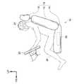
図1に示す車両用シート10はシート本体12を含んでいる。シート本体12は車両の運転席に設けられており、被験者の一例である車両の運転者20によって着座される。シート本体12に着座した運転者20は、車両の走行時に、ステアリングホイール22やペダル(図示省略)を操作して車両を運転する。なお、第1実施形態において、車両用シート10は特定の車種の車両に設けられる。[First Embodiment]
A
シート本体12はシートクッション部14、シートバック部16およびヘッドレスト部18を含んでいる。ヘッドレスト部18は、シートバック部16の車両上下方向上端部に、シートバック部16の長さ方向に沿ってスライド移動可能に取り付けられている。シートバック部16は、車両上下方向下端部が、シートクッション部14の車両前後方向後端部に、図示しない回動機構を介して取り付けられており、シートクッション部14に対し、車両幅方向に沿った軸回りに回動可能とされている。 The
また、車両用シート10は脳波計測装置24および脳波信号処理ECU(Electronic Control Unit)26を含んでいる。脳波計測装置24は、ヘルメット型で、シート本体12に着座した車両の運転者20の頭部に装着される。脳波計測装置24は、運転者20の頭部に装着された状態で、運転者20の脳波を計測し、計測した脳波を表す脳波信号を脳波信号処理ECU26へ無線通信により出力する。脳波計測装置24は脳波計測部の一例である。 The
脳波信号処理ECU26はシートクッション部14内に収納されている。図2に示すように、脳波信号処理ECU26は、CPU(Central Processing Unit)28と、ROM(Read Only Memory)、RAM(Random Access Memory)などのメモリ30と、HDD(Hard Disk Drive)、SSD(Solid State Drive)などの不揮発性の記憶部32と、を含んでいる。また脳波信号処理ECU26は、脳波計測装置24と無線通信を行うための無線通信部34と、音声出力機能および振動発生機能を備えた報知部36と、を含んでいる。CPU28、メモリ30、記憶部32、無線通信部34および報知部36は内部バス38を介して相互に通信可能に接続されている。 The electroencephalogram
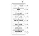
記憶部32は、脳波信号処理プログラム40を記憶している。脳波信号処理ECU26は、脳波信号処理プログラム40が記憶部32から読み出されてメモリ30に展開され、メモリ30に展開された脳波信号処理プログラム40がCPU28によって実行されることで、図3に示す各機能部として各々機能する。すなわち、脳波信号処理ECU26は、取得部60、異常値低減部62、第1フィルタ部64、DCオフセット低減部66、第2フィルタ部68、有意帯域判定部70および意識状態判定部72として各々機能する。なお、脳波信号処理ECU26は脳波信号処理装置の一例である。 The
取得部60は、脳波計測装置24から車両の運転者20の脳波信号を取得する。異常値低減部62は、取得部60によって取得された脳波信号に対し、振幅が閾値以上の異常値を低減する異常値低減処理を行う。第1フィルタ部64は、異常値低減部62による異常値低減処理を経た脳波信号に対し移動平均フィルタを掛ける第1フィルタ処理を行う。なお、移動平均フィルタは平滑化フィルタの一例である。DCオフセット低減部66は、第1フィルタ部64による第1フィルタ処理を経た脳波信号に対し、DCオフセット成分を低減するDCオフセット低減処理を行う。 The
第2フィルタ部68は、DCオフセット低減部66によるDCオフセット低減処理を経た脳波信号に対し、ハイパスフィルタおよびローパスフィルタを掛ける第2フィルタ処理を行う。有意帯域判定部70は、第2フィルタ部68による第2フィルタ処理を経た脳波信号のパワースペクトルにおける有意な周波数帯域を判定する。意識状態判定部72は、有意帯域判定部70によって判定された有意な周波数帯域から車両の運転者20の意識状態を判定する。 The
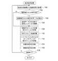
次に本第1実施形態の作用として、運転者20が車両の運転操作を行っている間、第1実施形態に係る脳波信号処理ECU26によって実行される脳波信号処理について、図4を参照して説明する。 Next, as an operation of the first embodiment, the electroencephalogram signal processing executed by the electroencephalogram
ステップ100において、取得部60は、運転者20の所定時間分の脳波を表す脳波信号を脳波計測装置24から無線通信により取得する。この脳波信号は、運転者20に瞬きや首振りなどの体動が発生した場合に、当該体動によるアーチファクトが加わる。また、車両の運転席に設けられる車両用シート10の周囲には電磁波源(例えばハーネスやカーナビ装置など)が存在しており、上記の脳波信号には、周囲に存在する電磁波源の配置などに応じて、環境に起因するアーチファクトが加わっている。また、脳波計測装置24と脳波信号処理ECU26との無線通信が行われた際には、上記の脳波信号に通信時のアーチファクトも加わる。 At
ステップ102において、異常値低減部62は、取得部60によって取得された脳波信号の中に、振幅が閾値電圧以上の部分が有るか否か判定する。このステップ102では、脳波信号に体動によるアーチファクトが加わっている部分が有るか否かを判定している。本実施形態では、非安静状態、より詳しくは車両の運転操作を行っている運転者20の脳波を取得するため、脳波信号に加わる体動によるアーチファクトの大きさが、被験者が安静状態の場合に比べて大きくなる。このため、第1実施形態では、上記の閾値電圧として150μV、或いはそれ以上の値(一例としては200μV)が予め設定されている。 At
ステップ102の判定が肯定された場合はステップ104へ移行する。ステップ104において、異常値低減部62は、取得部60によって取得された脳波信号のうち、振幅が閾値電圧以上の部分のデータを除去する。そして、ステップ106において、異常値低減部62は、ステップ104で除去したデータを、当該除去したデータの前後に存在するデータの中央値で補間し(中央値以外の中間値を用いてもよい)、ステップ108へ移行する。体動によるアーチファクトは振幅が大きいため、上記のようにステップ102~106(異常値低減部62による異常値低減処理の一例)では体動によるアーチファクトを先に低減している。なお、ステップ102の判定が否定された場合はステップ104,106をスキップしてステップ108へ移行する。 If the determination in
ステップ108において、第1フィルタ部64は、異常値低減部62による異常値低減処理を経た脳波信号に対し移動平均フィルタを掛ける第1フィルタ処理を行う。第1フィルタ処理では、脳波信号の変化を滑らかにすることで高周波成分を抑制している。なお、移動平均フィルタの区間は、車両用シート10が設けられる特定の車種の車両において、脳波信号に加わる体動によるアーチファクトに応じて予め設定されている。 In
ステップ110において、DCオフセット低減部66は、第1フィルタ部64による第1フィルタ処理を経た脳波信号に対し、DCオフセット成分を低減するDCオフセット低減処理を行う。DCオフセット低減処理では、通信時のアーチファクトを低減するために、主に低周波成分を抑制している。 At
ステップ112において、第2フィルタ部68は、DCオフセット低減部66によるDCオフセット低減処理を経た脳波信号に対し、ハイパスフィルタおよびローパスフィルタを掛ける第2フィルタ処理を行う。なお、ハイパスフィルタの遮断周波数およびローパスフィルタの遮断周波数は、車両用シート10が設けられる特定の車種の車両において、脳波信号に加わる環境に起因するアーチファクトの周波数帯域などに応じて予め設定されている。 At
第2フィルタ処理におけるフィルタ波形は山型であり、第2フィルタ処理を行ったとしても、フィルタの遮断周波数付近では除去しきれないアーチファクトが残ってしまう。本実施形態では、前記除去しきれないアーチファクトを最小限にするために、第1フィルタ部64による第1フィルタ処理、DCオフセット低減部66によるDCオフセット低減処理を予め行っている。 The filter waveform in the second filtering process is mountain-shaped, and even if the second filtering process is performed, artifacts that cannot be completely removed remain in the vicinity of the cut-off frequency of the filter. In this embodiment, the first filter processing by the
このように、本実施形態では、運転者20の脳波信号に対し、異常値低減部62による異常値低減処理、第1フィルタ部64による第1フィルタ処理、DCオフセット低減部66によるDCオフセット低減処理および第2フィルタ部68による第2フィルタ処理を順に行っている。これにより、例として図25にも示すような、各種のアーチファクトが低減された脳波信号を得ることができる。 As described above, in the present embodiment, the abnormal value reduction process by the abnormal
ステップ114において、有意帯域判定部70は、各種のアーチファクトが低減された脳波信号に対し、FFT(Fast Fourier Transform:高速フーリエ変換)を行ってパワースペクトルを求め、求めたパワースペクトルにおける有意な周波数帯域を判定する有意帯域判定処理を行う。この有意帯域判定処理には、脳波信号のパワースペクトル上で最大のピークが生じている周波数帯域を有意と判定する手法と、脳波信号のパワースペクトルをα波、β波、δ波、θ波などの周波数帯域毎に積分し、積分結果が最大値を示す周波数帯域を有意と判定する手法とがある。ステップ114では何れの手法を適用してもよい。 In
ステップ116において、意識状態判定部72は、有意帯域判定部70によって判定された有意な周波数帯域から車両の運転者20の意識状態を判定し、必要に応じて運転者20に警告する意識状態判定処理を行う。具体的には、例えば、有意帯域判定部70によって判定された有意な周波数帯域がθ波に相当する周波数帯域であった場合、意識状態判定部72は、運転者20が眠気を催している意識状態と判定し、報知部36から警告音や警告メッセージを出力させると共に報知部36で振動を発生させる。これにより、運転者20を覚醒させることができる。 In
ステップ118において、脳波信号処理ECU26は、運転者20による運転操作が終了したか否か判定する。ステップ118の判定が否定された場合はステップ100に戻り、ステップ118の判定が肯定される迄、ステップ100~ステップ118を繰り返す。運転者20による運転操作が終了すると、ステップ118の判定が肯定されて脳波信号処理を終了する。 At
以上説明したように、第1実施形態では、被験者の脳波信号を取得し、取得した脳波信号に対し振幅が閾値以上の異常値を低減する異常値低減処理を行う。また、異常値低減処理を経た脳波信号に対し平滑化フィルタを掛ける第1フィルタ処理を行う。また、第1フィルタ処理を経た脳波信号に対しDCオフセット成分を低減するDCオフセット低減処理を行う。そして、DCオフセット低減処理を経た脳波信号に対しハイパスフィルタおよびローパスフィルタを掛ける第2フィルタ処理を行う。これにより、構成の複雑化を招くことなく、脳波信号に含まれる各種のアーチファクトを低減することができる。 As described above, in the first embodiment, an electroencephalogram signal of a subject is acquired, and abnormal value reduction processing is performed to reduce anomalous values whose amplitude is equal to or greater than a threshold for the acquired electroencephalogram signal. Also, a first filter process is performed to apply a smoothing filter to the electroencephalogram signal that has undergone the abnormal value reduction process. Also, a DC offset reduction process is performed to reduce a DC offset component on the electroencephalogram signal that has undergone the first filter process. Then, a second filtering process is performed to apply a high-pass filter and a low-pass filter to the electroencephalogram signal that has undergone the DC offset reduction process. As a result, various artifacts contained in the electroencephalogram signal can be reduced without complicating the configuration.
また、第1実施形態では、異常値低減処理として、振幅が閾値以上を示すデータの値を、その前後のデータの中間値に置き換える処理を行う。これにより、振幅が閾値以上の異常値を低減する異常値低減処理を簡易な処理で実現することができる。 Further, in the first embodiment, as the abnormal value reduction process, a process of replacing a value of data whose amplitude is equal to or greater than a threshold value with an intermediate value of data before and after that value is performed. As a result, the abnormal value reduction process for reducing the abnormal value whose amplitude is equal to or greater than the threshold can be realized with a simple process.
また、第1実施形態では、第2フィルタ処理を経た脳波信号のパワースペクトルにおける有意な周波数帯域を判定し、判定した有意な周波数帯域から被験者の意識状態を判定する。これにより、各種のアーチファクトが低減された脳波信号から有意な周波数帯域を正確に判定することができ、被験者の意識状態を正確に判定することができる。 Further, in the first embodiment, the significant frequency band in the power spectrum of the electroencephalogram signal that has undergone the second filtering process is determined, and the state of consciousness of the subject is determined from the determined significant frequency band. Thereby, a significant frequency band can be accurately determined from the electroencephalogram signal with various artifacts reduced, and the state of consciousness of the subject can be accurately determined.
また、第1実施形態では、非安静状態の被験者の脳波信号を取得する。これにより、被験者が非安静状態であっても、各種のアーチファクトが低減された被験者の脳波信号を得ることができる。 Further, in the first embodiment, an electroencephalogram signal of a non-resting subject is acquired. As a result, even if the subject is in a non-resting state, it is possible to obtain an electroencephalogram signal of the subject in which various artifacts are reduced.
また、第1実施形態では、車両の運転を行っている被験者(運転者20)の脳波信号を取得する。これにより、被験者が車両の運転を行っている場合にも、各種のアーチファクトが低減された被験者の脳波信号を得ることができる。 Further, in the first embodiment, an electroencephalogram signal of a subject (driver 20) who is driving a vehicle is acquired. As a result, even when the subject is driving a vehicle, it is possible to obtain electroencephalogram signals of the subject in which various artifacts are reduced.
また、第1実施形態では、異常値低減処理における閾値は、150μVまたはそれを超える値としている。これにより、被験者が非安静状態である場合に、体動によるアーチファクトを適切に低減することができる。 Further, in the first embodiment, the threshold in the abnormal value reduction process is set to 150 μV or a value exceeding it. As a result, when the subject is in a non-resting state, artifacts due to body motion can be appropriately reduced.
〔第2実施形態〕
次に本開示の第2実施形態について説明する。なお、第1実施形態と同一の部分には同一の符号を付し、説明を省略する。[Second embodiment]
Next, a second embodiment of the present disclosure will be described. In addition, the same code|symbol is attached|subjected to the part same as 1st Embodiment, and description is abbreviate|omitted.
第2実施形態において、車両用シート10は、複数の車種のうち何れかの車種の車両に設けられる。図5に示すように、第2実施形態に係る脳波信号処理ECU26は、車両用シート10が設けられた車両(以下、「特定車両」という)に搭載されている車両側ECU50と通信線を介して接続されている。車両側ECU50は、脳波信号処理ECU26と同様に、CPU、メモリ、記憶部などを含んでおり、車両側ECU50の記憶部には特定車両の車種を表す車種IDが記憶されている。脳波信号処理ECU26は車両側ECU50から特定車両の車種IDを取得する。 In the second embodiment, the
脳波信号処理ECU26の記憶部32には処理パラメータDB42が記憶されている。本第2実施形態では、車両の車種毎に、脳波信号に加わる環境起因のアーチファクトが予め計測され、アーチファクトの計測結果に応じて、車両の車種毎に処理パラメータが予め定められている。ここで、処理パラメータは、第2フィルタ部68による第2フィルタ処理におけるハイパスフィルタの遮断周波数およびローパスフィルタの遮断周波数を含む。図6に示すように、処理パラメータDB42には、車両の車種毎に定められた処理パラメータが、車種IDと対応付けて登録されている。 A
また、第2実施形態において、無線通信部34は、運転者20に装着されるスマートウォッチなどのウェアラブル端末52と無線通信を行うことが可能とされている。ウェアラブル端末52は、運転者20の汗の掻き易さのレベルなどの体質を検知する機能を有しており、当該機能によって検知した運転者20の汗の掻き易さのレベルを含む体質を、運転者20の体質情報として脳波信号処理ECU26へ送信する。 Further, in the second embodiment, the
脳波信号処理ECU26の記憶部32には閾値DB44が記憶されている。本第2実施形態では、運転者20の体質(例えば汗の掻き易さのレベルなど)毎に、異常値低減部62による異常値低減処理における閾値が予め定められている。図7に示すように、閾値DB44には、運転者20の体質(例えば汗の掻き易さのレベルなど)毎に定められた前記閾値が、運転者20の体質情報と対応付けて登録されている。 A
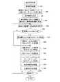
第2実施形態において、脳波信号処理ECU26は、車両側ECU50と通信を行うための通信部46(図5参照)を含んでいる。また脳波信号処理ECU26は、図8に示すパラメータ設定部74としても機能する。パラメータ設定部74は、第2実施形態に係る脳波信号処理(図9参照)のうち、ステップ90~ステップ96の処理を行う。 In the second embodiment, the electroencephalogram
すなわち、ステップ90において、パラメータ設定部74は、車両側ECU50から特定車両の車種IDを取得する。ステップ92において、パラメータ設定部74は、ステップ90で取得した車種IDと対応付けて処理パラメータDB42に登録されている処理パラメータを読み出す。そして、読み出した処理パラメータのうち、第2フィルタ処理におけるハイパスフィルタの遮断周波数およびローパスフィルタの遮断周波数を第2フィルタ部68に設定する。なお、上記の車種IDは第2情報の一例である。 That is, at
また、ステップ94において、パラメータ設定部74は、ウェアラブル端末52から運転者20の体質情報を取得する。ステップ96において、パラメータ設定部74は、ステップ94で取得した体質情報と対応付けて閾値DB44に登録されている閾値を読み出し、読み出した閾値を異常値低減部62に設定する。なお、上記の体質情報は第1情報の一例である。また、第2実施形態に係る脳波信号処理(図9)において、ステップ94、95はステップ90、92よりも先に実行してもよい。また、ステップ90、92はステップ112よりも先に実行すればよく、脳波信号処理(図9)の最初に実行しなくても構わない。 Also, at
上記のように、第2実施形態では、被験者の脳波信号に含まれる被験者の体動によるアーチファクトに関連する第1情報(運転者の体質情報)を取得し、取得した第1情報に基づいて、少なくとも異常値低減処理の処理パラメータを設定する。これにより体動によるアーチファクトを適切に低減することができる。 As described above, in the second embodiment, the first information (driver's constitution information) related to the artifact due to the subject's body movement included in the subject's electroencephalogram signal is acquired, and based on the acquired first information, At least the processing parameters for the abnormal value reduction processing are set. As a result, artifacts due to body motion can be appropriately reduced.
また、第2実施形態では、被験者の脳波信号に含まれる環境に起因するアーチファクトに関連する第2情報(車種ID)を取得し、取得した第2情報に基づいて第2フィルタ処理のハイパスフィルタおよびローパスフィルタの処理パラメータを設定する。これにより、環境に起因するアーチファクトを適切に低減することができる。 Further, in the second embodiment, the second information (vehicle type ID) related to the artifacts caused by the environment contained in the electroencephalogram signal of the subject is acquired, and based on the acquired second information, the high-pass filter and the Sets the processing parameters for the low-pass filter. As a result, artifacts caused by the environment can be appropriately reduced.
なお、第2実施形態では、被験者の体動によるアーチファクトに関連する第1情報(運転者の体質情報)を取得し、取得した第1情報に基づいて異常値低減処理の処理パラメータ(閾値)を設定する態様を説明した。しかし、本開示はこれに限定されるものではなく、取得した第1情報に基づき、異常値低減処理の処理パラメータに加えて第1フィルタ処理の処理パラメータ(例えば移動平均フィルタの区間)も設定するようにしてもよい。但し、移動平均フィルタの区間は、値を長くし過ぎると(例えば30秒以上にすると)、後段の意識状態判定処理に悪影響を及ぼす可能性があるので、概ね5~10秒の範囲内の値を設定することが好ましい。 Note that in the second embodiment, the first information (driver's constitution information) related to artifacts due to the subject's body movement is acquired, and the processing parameter (threshold value) for the abnormal value reduction processing is set based on the acquired first information. The setting mode has been described. However, the present disclosure is not limited to this, and based on the acquired first information, in addition to the processing parameters for the abnormal value reduction processing, the processing parameters for the first filter processing (for example, the interval of the moving average filter) are also set. You may do so. However, if the interval of the moving average filter is set too long (for example, 30 seconds or more), it may adversely affect the subsequent consciousness state determination processing, so a value within the range of 5 to 10 seconds is preferably set.
また、第2実施形態では、運転者20の汗の掻き易さのレベルなどの体質をウェアラブル端末52が検知する態様を説明したが、本開示はこれに限定されるものではない。例えば、車両用シート10のシート本体12に生体センサを内蔵させておき、当該生体センサによって運転者20の汗の掻き易さのレベルなどの体質を検知するようにしてもよい。 Further, in the second embodiment, a mode in which the
また、上記では平滑化フィルタの一例として移動平均フィルタを適用した態様を説明したが、本開示はこれに限定されるものではなく、例えば加重平均フィルタ、重み付けされた移動平均フィルタ、指数移動平均フィルタなどの他の平滑化フィルタを適用してもよい。 In addition, although the above describes a mode in which a moving average filter is applied as an example of a smoothing filter, the present disclosure is not limited to this, for example, a weighted average filter, a weighted moving average filter, an exponential moving average filter Other smoothing filters such as
また、上記では車両用シート10の脳波信号処理ECU26が、有意帯域判定処理および意識状態判定処理も行う態様を説明したが、本開示はこれに限定されるものではない。例えば、車両用シート10の脳波信号処理ECU26は、各種のアーチファクトが低減された脳波信号を外部装置(例えば車両側ECU50)へ出力し、外部装置で有意帯域判定処理および意識状態判定処理を行うようにしてもよい。 In the above description, the electroencephalogram
さらに、上記では本開示に係る脳波信号処理装置の一例である脳波信号処理ECU26が車両用シート10に組み込まれており、車両の運転操作を行う運転者20の脳波信号を処理する態様を説明したが、本開示はこれに限定されるものではない。本開示によれば、被験者が非安静状態であっても各種のアーチファクトが低減された脳波信号を得ることができるので、本開示は様々な脳波応用技術へ適用可能である。 Furthermore, in the above description, the electroencephalogram
また、上記では本開示に係る脳波信号処理プログラム40が記憶部32に予め記憶(インストール)されている態様を説明したが、本開示に係る脳波信号処理プログラムは、HDD、SSD、DVD等の非一時的記録媒体に記録されている形態で提供することも可能である。 In the above description, the electroencephalogram
次に、本開示に係る脳波信号処理方法の有効性を検証するために、本願発明者等が実施した実験について説明する。 Next, experiments conducted by the inventors of the present application to verify the effectiveness of the electroencephalogram signal processing method according to the present disclosure will be described.
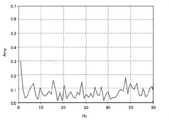
この実験では、真性脳波信号を模擬する信号として15Hzのsin波(図10参照)を用いた。この15Hzのsin波に対してFFTを行って求めたパワースペクトルを図11に示す。また、脳波信号に重畳される各種のアーチファクトを模擬するために、15Hzのsin波に、通信時のアーチファクトを模擬する1Hzのsin波および環境に起因するアーチファクトを模擬する50Hzのsin波を掛け合わせ、さらに、体動によるアーチファクトを模擬するランダムノイズを付加した疑似脳波信号を作成した(図12)。この疑似脳波信号に対してFFTを行って求めたパワースペクトルを図13に示す。なお、体動によるアーチファクトをランダムノイズによって模擬しているのは、体動によるアーチファクトを、想定外の体動によるアーチファクトであっても低減できるか否かを確認するためである。 In this experiment, sin waves of 15 Hz (see FIG. 10) were used as signals simulating true electroencephalogram signals. FIG. 11 shows the power spectrum obtained by performing FFT on this 15 Hz sine wave. In addition, in order to simulate various artifacts superimposed on the electroencephalogram signal, the 15 Hz sine wave is multiplied by a 1 Hz sine wave that simulates communication artifacts and a 50 Hz sine wave that simulates environmental artifacts. Furthermore, a pseudo electroencephalogram signal was created by adding random noise to simulate artifacts due to body movement (Fig. 12). FIG. 13 shows the power spectrum obtained by performing FFT on this pseudo electroencephalogram signal. The reason why the artifact due to body movement is simulated with random noise is to confirm whether or not the artifact due to body movement can be reduced even if it is an artifact due to unexpected body movement.
図13に示す疑似脳波信号のパワースペクトルでは、通信時のアーチファクトに対応する周波数成分が1Hz付近に現れており、環境に起因するアーチファクトに対応する周波数成分が50Hz付近に現れている。また、体動によるアーチファクトに対応するランダムなノイズ成分が全ての周波数帯域に現れており、真性脳波信号に相当する15Hzの周波数成分はノイズに隠れてしまっている。 In the power spectrum of the pseudo electroencephalogram signal shown in FIG. 13, frequency components corresponding to communication artifacts appear around 1 Hz, and frequency components corresponding to environmental artifacts appear around 50 Hz. Also, random noise components corresponding to artifacts due to body motion appear in all frequency bands, and the 15 Hz frequency component corresponding to the true electroencephalogram signal is hidden by the noise.
本開示に係る脳波信号処理方法を適用した脳波信号処理は、図4にも示すように、脳波信号を取得した後、(1)異常値低減処理(ステップ102~106)、(2)第1フィルタ処理(移動平均フィルタ)(ステップ108)、(3)DCオフセット低減処理(ステップ110)、(4)第2フィルタ処理(ハイパスフィルタおよびローパスフィルタ)(ステップ112)、の各処理を番号順に行っている。まずは前述の疑似脳波信号に対し、(1)~(4)の各処理を単独で行った実験の結果を説明する。 As shown in FIG. 4, electroencephalogram signal processing to which the electroencephalogram signal processing method according to the present disclosure is applied includes (1) abnormal value reduction processing (
疑似脳波信号に対して(1)異常値低減処理のみを行った場合の脳波信号のパワースペクトルを図14に示す。(1)異常値低減処理のみを行った場合、真性脳波信号に相当する15Hzの周波数成分が減衰してしまっている。また、1Hzのピークが高く、50Hzにも15Hzと同程度のパワーを持つピークが存在している。このため、後段における運転者の意識状態の判定で誤判定が発生する虞がある。 FIG. 14 shows the power spectrum of the electroencephalogram signal when only (1) outlier reduction processing is performed on the pseudo electroencephalogram signal. (1) When only the abnormal value reduction processing is performed, the frequency component of 15 Hz corresponding to the true electroencephalogram signal is attenuated. Also, the peak at 1 Hz is high, and there is a peak at 50 Hz that has power similar to that at 15 Hz. For this reason, there is a possibility that an erroneous determination may occur in determining the state of consciousness of the driver in the subsequent stage.
また、疑似脳波信号に対して(2)第1フィルタ処理(移動平均フィルタ)のみを行った場合の脳波信号のパワースペクトルを図15に示す。(2)第1フィルタ処理(移動平均フィルタ)のみを行った場合、真性脳波信号に相当する15Hzの周波数成分の減衰は見られないものの、1Hzのピークが高く、50Hzにも15Hzと同程度のパワーを持つピークが存在している。このため、後段における運転者の意識状態の判定で誤判定が発生する虞がある。 FIG. 15 shows the power spectrum of the electroencephalogram signal when only the (2) first filtering process (moving average filter) is performed on the pseudo electroencephalogram signal. (2) When only the first filtering process (moving average filter) is performed, although there is no attenuation of the 15 Hz frequency component corresponding to the true electroencephalogram signal, the peak at 1 Hz is high, and the peak at 50 Hz is similar to that at 15 Hz. There is a peak with power. For this reason, there is a possibility that an erroneous determination may occur in determining the state of consciousness of the driver in the subsequent stage.
また疑似脳波信号に対して(3)DCオフセット低減処理のみを行った場合の脳波信号のパワースペクトルを図16に示す。(3)DCオフセット低減処理のみを行った場合、1Hzのピークをカットすることができるものの、50Hzに15Hzと同程度のパワーを持つピークが存在している。このため、後段における運転者の意識状態の判定で誤判定が発生する虞がある。 FIG. 16 shows the power spectrum of the electroencephalogram signal when only the (3) DC offset reduction process is performed on the pseudo electroencephalogram signal. (3) When only the DC offset reduction process is performed, the peak at 1 Hz can be cut, but there is a peak at 50 Hz that has the same power as that at 15 Hz. For this reason, there is a possibility that an erroneous determination may occur in determining the state of consciousness of the driver in the subsequent stage.
また、疑似脳波信号に対して(4)第2フィルタ処理(ハイパスフィルタおよびローパスフィルタ)のみを行った場合の脳波信号のパワースペクトルを図17に示す。(4)第2フィルタ処理(ハイパスフィルタおよびローパスフィルタ)のみを行った場合、およそ10Hz付近にピークが現れており、真性脳波信号に相当する15Hzの周波数成分が減衰して他の周波数成分に隠れてしまっている。このため、後段における運転者の意識状態の判定で誤判定が発生する。 FIG. 17 shows the power spectrum of the electroencephalogram signal when only (4) second filtering (high-pass filter and low-pass filter) is performed on the pseudo electroencephalogram signal. (4) When only the second filtering process (high-pass filter and low-pass filter) is performed, a peak appears around 10 Hz, and the 15 Hz frequency component corresponding to the intrinsic electroencephalogram signal is attenuated and hidden behind other frequency components. It's gone. Therefore, an erroneous determination occurs in the determination of the state of consciousness of the driver in the latter stage.
上述したように、(1)~(4)の各処理を単独で行った場合の脳波信号のパワースペクトル(図14~図17)は、何れも、真性脳波信号を模擬する15Hzの周波数成分がその他の周波数帯域の成分に対して顕著に大きくはなっておらず、アーチファクトを低減する性能が不十分であることが明らかである。 As described above, the power spectrum of the electroencephalogram signal (FIGS. 14 to 17) when each of the processes (1) to (4) is performed alone shows that the 15 Hz frequency component that simulates the true electroencephalogram signal is It is clear that the performance of reducing artifacts is insufficient because it does not become significantly larger than the components of other frequency bands.
続いて、疑似脳波信号に対し、(1)~(4)の各処理を番号順に行った場合(本開示に係る脳波信号処理方法に則った順序で行った場合)の結果を説明する。 Subsequently, the results when the processes (1) to (4) are performed on the pseudo electroencephalogram signal in numerical order (when performed in the order according to the electroencephalogram signal processing method according to the present disclosure) will be described.
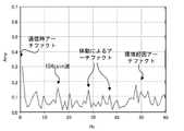
まず、疑似脳波信号に対して(1)異常値低減処理を行った場合、脳波信号の波形は図12から図18に示すように変化し、そのパワースペクトルは図13から図19に示すように変化する。図19に示すパワースペクトルでは、50Hzの周波数成分が低下し、15Hzの周波数成分が少し目立ってきているが、各アーチファクトは十分には低減されていないので不完全な状態と言える。このため、後段における運転者の意識状態の判定において、どの周波数帯域が有意なのかについて誤判定が発生する虞がある。 First, when (1) abnormal value reduction processing is performed on the pseudo electroencephalogram signal, the waveform of the electroencephalogram signal changes as shown in FIGS. 12 to 18, and its power spectrum changes as shown in FIGS. Change. In the power spectrum shown in FIG. 19, the frequency component of 50 Hz has decreased and the frequency component of 15 Hz has become somewhat conspicuous. For this reason, there is a possibility that an erroneous determination as to which frequency band is significant may occur in determining the state of consciousness of the driver in the subsequent stage.
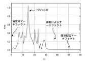
次に(1)異常値低減処理を経た脳波信号に対して(2)第1フィルタ処理(移動平均フィルタ)を行った場合、脳波信号の波形は図18から図20に示すように変化し、そのパワースペクトルは図19から図21に示すように変化する。図21に示すパワースペクトルでは、15Hzの周波数成分が少し目立ってきているが、各アーチファクトは十分には低減されていないので不完全な状態と言える。このため、後段における運転者の意識状態の判定において、どの周波数帯域が有意なのかについて誤判定が発生する虞がある。 Next, when (2) first filtering (moving average filter) is performed on the electroencephalogram signal that has undergone (1) abnormal value reduction processing, the waveform of the electroencephalogram signal changes as shown in FIGS. 18 to 20, The power spectrum changes as shown in FIGS. 19-21. In the power spectrum shown in FIG. 21, the frequency component of 15 Hz is becoming more noticeable, but each artifact is not sufficiently reduced, so it can be said that the state is incomplete. For this reason, there is a possibility that an erroneous determination as to which frequency band is significant may occur in determining the state of consciousness of the driver in the subsequent stage.
次に(1)異常値低減処理→(2)第1フィルタ処理(移動平均フィルタ)を経た脳波信号に対して(3)DCオフセット低減処理を行った場合、脳波信号の波形は図20から図22に示すように変化し、そのパワースペクトルは図21から図23に示すように変化する。図22を図20と比較しても明らかなように、DCオフセット低減処理を経た脳波信号は、振幅の中心が0付近へ変化している。図23に示すパワースペクトルでは、1Hz付近の周波数成分(通信時のアーチファクト)が半分程度まで抑えられてはいるものの、各アーチファクトは十分には低減されていないので不完全な状態と言える。このため、後段における運転者の意識状態の判定において、どの周波数帯域が有意なのかについて誤判定が発生する虞がある。 Next, when (3) DC offset reduction processing is performed on the electroencephalogram signal that has undergone (1) abnormal value reduction processing → (2) first filter processing (moving average filter), the waveform of the electroencephalogram signal is shown in FIGS. 22, and its power spectrum changes as shown in FIGS. 21 to 23. FIG. As is clear from comparing FIG. 22 with FIG. 20, the center of the amplitude of the electroencephalogram signal that has undergone the DC offset reduction process changes to near zero. In the power spectrum shown in FIG. 23, the frequency components around 1 Hz (artifacts during communication) are suppressed by about half, but each artifact is not sufficiently reduced, so it can be said that the state is incomplete. For this reason, there is a possibility that an erroneous determination as to which frequency band is significant may occur in determining the state of consciousness of the driver in the subsequent stage.
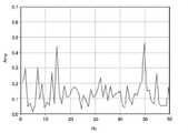
さらに(1)異常値低減処理→(2)第1フィルタ処理(移動平均フィルタ)→(3)DCオフセット低減処理を経た脳波信号に対して(4)第2フィルタ処理(ハイパスフィルタおよびローパスフィルタ)を行った場合、脳波信号の波形は図22から図24に示すように変化し、そのパワースペクトルは図23から図25に示すように変化する。図25に示すパワースペクトルでは、各アーチファクトが十分に低減され、真性脳波信号に相当する15Hzの周波数成分が顕著なピークを示している。このため、後段における運転者の意識状態の判定において、15Hz付近の周波数帯域が有意であると間違いなく判定することができる。 Further, (1) Abnormal value reduction processing→(2) First filter processing (moving average filter)→(3) DC offset reduction processing (4) Second filter processing (high-pass filter and low-pass filter) , the waveform of the electroencephalogram signal changes as shown in FIGS. 22 to 24, and the power spectrum changes as shown in FIGS. In the power spectrum shown in FIG. 25, each artifact is sufficiently reduced, and the 15 Hz frequency component corresponding to the true electroencephalogram signal shows a prominent peak. Therefore, it can be definitely determined that the frequency band around 15 Hz is significant in determining the state of consciousness of the driver in the subsequent stage.
さらに、本願発明者等は(1)~(4)の各処理を番号順に行う(本開示に係る脳波信号処理方法に則った順序で行う)ことの有効性を検証するために、各処理の実行順序を変えて各処理を行い、パワースペクトルを確認する実験を行った。この実験の結果を説明する。 Furthermore, the inventors of the present application conducted the processing in order to verify the effectiveness of performing each processing (1) to (4) in numerical order (performing in the order according to the electroencephalogram signal processing method according to the present disclosure). An experiment was conducted to confirm the power spectrum by performing each process by changing the order of execution. The results of this experiment will be described.
第1の実行順序は、DCオフセット低減処理を最初に行うものである。すなわち、疑似脳波信号に対して、(3)DCオフセット低減処理→(1)異常値低減処理→(2)第1フィルタ処理(移動平均フィルタ)→(4)第2フィルタ処理(ハイパスフィルタおよびローパスフィルタ)、の順序で各処理を行うものである。第1の実行順序で各処理を行って得られた脳波信号のパワースペクトルを図26に示す。 The first execution order is to perform the DC offset reduction process first. That is, for the pseudo electroencephalogram signal, (3) DC offset reduction processing → (1) abnormal value reduction processing → (2) first filter processing (moving average filter) → (4) second filter processing (high-pass filter and low-pass filter). FIG. 26 shows the power spectrum of the electroencephalogram signal obtained by performing each process in the first execution order.
図26に示すパワースペクトルでは、真性脳波信号に相当する15Hzの周波数成分が最大のピークになってはいるものの、25Hz付近の周波数成分のピークもそれに劣らず高い。このため、図26に示すパワースペクトルに対し、最大のピークが生じている周波数帯域を有意と判定する有意帯域判定処理を行った場合、有意な周波数帯域を誤判定する虞がある。また、図26に示すパワースペクトルは、5Hz付近~28Hz付近の周波数帯域について、平均的にレベルが高くなっている。このため、図26に示すパワースペクトルに対し、周波数帯域毎に積分した結果が最大値を示す周波数帯域を有意と判定する有意帯域判定処理を行った場合にも、有意な周波数帯域を誤判定する虞がある。 In the power spectrum shown in FIG. 26, the frequency component at 15 Hz, which corresponds to the true electroencephalogram signal, has the maximum peak, but the peaks of the frequency components near 25 Hz are equally high. For this reason, when the significant band determination process for determining the frequency band in which the maximum peak occurs is significant with respect to the power spectrum shown in FIG. 26, there is a possibility that the significant frequency band is erroneously determined. Also, the power spectrum shown in FIG. 26 has a high level on average in the frequency band from around 5 Hz to around 28 Hz. For this reason, even when performing the significant band determination process for determining that the frequency band in which the result of integration for each frequency band shows the maximum value is performed on the power spectrum shown in FIG. 26, the significant frequency band is erroneously determined. There is fear.
第2の実行順序は、第2フィルタ処理(ハイパスフィルタおよびローパスフィルタ)を最初に行うものである。すなわち、疑似脳波信号に対して、(4)第2フィルタ処理(ハイパスフィルタおよびローパスフィルタ)→(1)異常値低減処理→(2)第1フィルタ処理(移動平均フィルタ)→(3)DCオフセット低減処理、の順序で各処理を行うものである。第2の実行順序で各処理を行って得られた脳波信号のパワースペクトルを図27に示す。 A second execution order is to perform the second filtering (high-pass filtering and low-pass filtering) first. That is, for the pseudo electroencephalogram signal, (4) second filtering (high-pass filter and low-pass filter) → (1) abnormal value reduction → (2) first filtering (moving average filter) → (3) DC offset reduction processing. FIG. 27 shows the power spectrum of the electroencephalogram signal obtained by performing each process in the second execution order.
図27に示すパワースペクトルでは、7Hz付近に最大のピークがあり、真性脳波信号に相当する15Hz付近のピークは減衰してしまっている。このため、図27に示すパワースペクトルに対し、最大のピークが生じている周波数帯域を有意と判定する有意帯域判定処理を行った場合、有意な周波数帯の誤判定が発生する。また、図27に示すパワースペクトルは、7Hz付近~28Hz付近の周波数帯域に幾つかのピークが存在している。このため、図27に示すパワースペクトルに対し、周波数帯域毎に積分した結果が最大値を示す周波数帯域を有意と判定する有意帯域判定処理を行った場合にも、有意な周波数帯域を誤判定する虞がある。 In the power spectrum shown in FIG. 27, there is a maximum peak near 7 Hz, and the peak near 15 Hz corresponding to the true electroencephalogram signal is attenuated. For this reason, when the significant band determination process for determining the frequency band in which the maximum peak occurs is significant with respect to the power spectrum shown in FIG. 27, erroneous determination of the significant frequency band occurs. Also, the power spectrum shown in FIG. 27 has several peaks in the frequency band from around 7 Hz to around 28 Hz. For this reason, even when the significant band determination process is performed to determine that the frequency band in which the result of integration for each frequency band shows the maximum value is performed on the power spectrum shown in FIG. 27, the significant frequency band is erroneously determined. There is fear.
第3の実行順序は、第1フィルタ処理(移動平均フィルタ)を最初に行うものである。すなわち、疑似脳波信号に対して、(2)第1フィルタ処理(移動平均フィルタ)→(1)異常値低減処理→(3)DCオフセット低減処理→(4)第2フィルタ処理(ハイパスフィルタおよびローパスフィルタ)、の順序で各処理を行うものである。第3の実行順序で各処理を行って得られた脳波信号のパワースペクトルを図28に示す。 The third execution order is to perform the first filter process (moving average filter) first. That is, for the pseudo electroencephalogram signal, (2) first filtering (moving average filter) → (1) abnormal value reduction → (3) DC offset reduction → (4) second filtering (high-pass filter and low-pass filter). FIG. 28 shows the power spectrum of the electroencephalogram signal obtained by performing each process in the third execution order.
図28に示すパワースペクトルでは、真性脳波信号に相当する15Hz付近のピークがカットされて無くなってしまっており、8Hz付近および23Hz付近に高いピークがある。このため、図28に示すパワースペクトルに対し、最大のピークが生じている周波数帯域を有意と判定する有意帯域判定処理を行った場合、有意な周波数帯の誤判定が発生する。また、周波数帯域毎に積分した結果が最大値を示す周波数帯域を有意と判定する有意帯域判定処理を行った場合にも、有意な周波数帯域を誤判定する虞がある。 In the power spectrum shown in FIG. 28, the peak near 15 Hz corresponding to the true electroencephalogram signal is cut off, and there are high peaks near 8 Hz and 23 Hz. For this reason, when the significant band determination process for determining the frequency band in which the maximum peak occurs is significant with respect to the power spectrum shown in FIG. 28, erroneous determination of the significant frequency band occurs. Further, even when the significant band determination process is performed to determine that the frequency band in which the result of integration for each frequency band exhibits the maximum value is significant, there is a possibility that the significant frequency band is erroneously determined.
第4の実行順序は、DCオフセット低減処理を最後に行うものである。すなわち、疑似脳波信号に対して、(1)異常値低減処理→(2)第1フィルタ処理(移動平均フィルタ)→(4)第2フィルタ処理(ハイパスフィルタおよびローパスフィルタ)→(3)DCオフセット低減処理、の順序で各処理を行うものである。第4の実行順序で各処理を行って得られた脳波信号のパワースペクトルを図29に示す。 The fourth execution order is to perform the DC offset reduction process last. That is, for the pseudo electroencephalogram signal, (1) abnormal value reduction processing → (2) first filtering processing (moving average filter) → (4) second filtering processing (high-pass filter and low-pass filter) → (3) DC offset reduction processing. FIG. 29 shows the power spectrum of the electroencephalogram signal obtained by performing each process in the fourth execution order.
図29に示すパワースペクトルでは、5Hz付近および7Hz付近に高いピークがあり、真性脳波信号に相当する15Hz付近には明瞭なピークが存在していない。このため、図29に示すパワースペクトルに対し、最大のピークが生じている周波数帯域を有意と判定する有意帯域判定処理を行った場合、有意な周波数帯の誤判定が発生する。また、周波数帯域毎に積分した結果が最大値を示す周波数帯域を有意と判定する有意帯域判定処理を行った場合にも、有意な周波数帯域を誤判定する虞がある。 The power spectrum shown in FIG. 29 has high peaks near 5 Hz and 7 Hz, and does not have a clear peak near 15 Hz, which corresponds to the true electroencephalogram signal. Therefore, when the significant band determination process for determining the frequency band in which the maximum peak occurs is significant with respect to the power spectrum shown in FIG. 29, erroneous determination of the significant frequency band occurs. Further, even when the significant band determination process is performed to determine that the frequency band in which the result of integration for each frequency band exhibits the maximum value is significant, there is a possibility that the significant frequency band is erroneously determined.
第5の実行順序は、異常値低減処理を最後に行うものである。すなわち、疑似脳波信号に対して、(2)第1フィルタ処理(移動平均フィルタ)→(3)DCオフセット低減処理→(4)第2フィルタ処理(ハイパスフィルタおよびローパスフィルタ)→(1)異常値低減処理、の順序で各処理を行うものである。第5の実行順序で各処理を行って得られた脳波信号のパワースペクトルを図30に示す。 In the fifth execution order, the abnormal value reduction process is performed last. That is, for the pseudo electroencephalogram signal, (2) first filtering (moving average filter) → (3) DC offset reduction processing → (4) second filtering (high-pass filter and low-pass filter) → (1) abnormal value reduction processing. FIG. 30 shows the power spectrum of the electroencephalogram signal obtained by performing each process in the fifth execution order.
図30に示すパワースペクトルでは、11Hz付近に高いピークがあり、真性脳波信号に相当する15Hz付近にはピークは存在するもの、その高さは比較的低い。このため、図30に示すパワースペクトルに対し、最大のピークが生じている周波数帯域を有意と判定する有意帯域判定処理を行った場合、有意な周波数帯の誤判定が発生する。また、周波数帯域毎に積分した結果が最大値を示す周波数帯域を有意と判定する有意帯域判定処理を行った場合にも、有意な周波数帯域を誤判定する虞がある。 The power spectrum shown in FIG. 30 has a high peak near 11 Hz and a peak near 15 Hz corresponding to the true brain wave signal, but the height is relatively low. Therefore, when the significant band determination process for determining the frequency band in which the maximum peak occurs is significant for the power spectrum shown in FIG. 30, erroneous determination of the significant frequency band occurs. Further, even when the significant band determination process is performed to determine that the frequency band in which the result of integration for each frequency band exhibits the maximum value is significant, there is a possibility that the significant frequency band is erroneously determined.
第6の実行順序は、第1フィルタ処理(移動平均フィルタ)を最後に行うものである。すなわち、疑似脳波信号に対して、(1)異常値低減処理→(3)DCオフセット低減処理→(4)第2フィルタ処理(ハイパスフィルタおよびローパスフィルタ)→(2)第1フィルタ処理(移動平均フィルタ)、の順序で各処理を行うものである。第6の実行順序で各処理を行って得られた脳波信号のパワースペクトルを図31に示す。 The sixth execution order is to perform the first filtering (moving average filtering) last. That is, for the pseudo electroencephalogram signal, (1) abnormal value reduction processing → (3) DC offset reduction processing → (4) second filter processing (high-pass filter and low-pass filter) → (2) first filter processing (moving average filter). FIG. 31 shows the power spectrum of the electroencephalogram signal obtained by performing each process in the sixth execution order.
図31に示すパワースペクトルでは、27Hz付近に高いピークがあり、次に高いピークは20Hz付近である。そして真性脳波信号に相当する15Hz付近には明瞭なピークは存在していない。このため、図31に示すパワースペクトルに対し、最大のピークが生じている周波数帯域を有意と判定する有意帯域判定処理を行った場合、有意な周波数帯の誤判定が発生する。また、周波数帯域毎に積分した結果が最大値を示す周波数帯域を有意と判定する有意帯域判定処理を行った場合にも、有意な周波数帯域を誤判定する虞がある。 In the power spectrum shown in FIG. 31, there is a high peak around 27 Hz, and the next highest peak is around 20 Hz. There is no clear peak near 15 Hz, which corresponds to the true electroencephalogram signal. For this reason, when the significant band determination process for determining the frequency band in which the maximum peak occurs is significant with respect to the power spectrum shown in FIG. 31, erroneous determination of the significant frequency band occurs. Further, even when the significant band determination process is performed to determine that the frequency band in which the result of integration for each frequency band exhibits the maximum value is significant, there is a possibility that the significant frequency band is erroneously determined.
第7の実行順序は、DCオフセット低減処理と第1フィルタ処理(移動平均フィルタ)の実行順序を入れ替えたものである。すなわち、疑似脳波信号に対して、(1)異常値低減処理→(3)DCオフセット低減処理→(2)第1フィルタ処理(移動平均フィルタ)→(4)第2フィルタ処理(ハイパスフィルタおよびローパスフィルタ)、の順序で各処理を行うものである。第7の実行順序で各処理を行って得られた脳波信号のパワースペクトルを図32に示す。 The seventh execution order is obtained by switching the execution order of the DC offset reduction process and the first filter process (moving average filter). That is, for the pseudo electroencephalogram signal, (1) abnormal value reduction processing → (3) DC offset reduction processing → (2) first filter processing (moving average filter) → (4) second filter processing (high-pass filter and low-pass filter). FIG. 32 shows the power spectrum of the electroencephalogram signal obtained by performing each process in the seventh execution order.
図32に示すパワースペクトルでは、22Hz付近に高いピークがあり、次に高いピークは19Hz付近である。そして真性脳波信号に相当する15Hz付近には多少のピークは存在しているもの、その高さは低い。このため、図32に示すパワースペクトルに対し、最大のピークが生じている周波数帯域を有意と判定する有意帯域判定処理を行った場合、有意な周波数帯の誤判定が発生する。また、周波数帯域毎に積分した結果が最大値を示す周波数帯域を有意と判定する有意帯域判定処理を行った場合にも、有意な周波数帯域を誤判定する虞がある。 In the power spectrum shown in FIG. 32, there is a high peak around 22 Hz and the next highest peak is around 19 Hz. Although there are some peaks around 15 Hz corresponding to the true electroencephalogram signal, the height is low. Therefore, when the significant band determination process for determining the frequency band in which the maximum peak occurs is significant for the power spectrum shown in FIG. 32, erroneous determination of the significant frequency band occurs. Further, even when the significant band determination process is performed to determine that the frequency band in which the result of integration for each frequency band exhibits the maximum value is significant, there is a possibility that the significant frequency band is erroneously determined.
以上の結果から、脳波信号に対しては、(1)~(4)の各処理を番号順に行う(本開示に係る脳波信号処理方法に則った順序で行う)ことが、各種のアーチファクトを低減した、真性脳波信号に近い脳波信号を得る上で非常に有効であることが確認できた。 From the above results, it can be seen that performing each of the processes (1) to (4) on the electroencephalogram signal in numerical order (performing in the order according to the electroencephalogram signal processing method according to the present disclosure) reduces various artifacts. It was confirmed that this method is very effective in obtaining electroencephalogram signals close to true electroencephalogram signals.
10 車両用シート
12 シート本体
24 脳波計測装置
26 脳波信号処理ECU
40 脳波信号処理プログラム
60 取得部
62 異常値低減部
64 第1フィルタ部
66 DCオフセット低減部
68 第2フィルタ部
70 有意帯域判定部
72 意識状態判定部
74 パラメータ設定部10
40 electroencephalogram
Claims (11)
Translated fromJapanese取得した脳波信号に対し振幅が閾値以上の異常値を低減する異常値低減処理を行い、
前記異常値低減処理を経た脳波信号に対し平滑化フィルタを掛ける第1フィルタ処理を行い、
前記第1フィルタ処理を経た脳波信号に対しDCオフセット成分を低減するDCオフセット低減処理を行い、
前記DCオフセット低減処理を経た脳波信号に対しハイパスフィルタおよびローパスフィルタを掛ける第2フィルタ処理を行う
脳波信号処理方法。Acquiring the subject's electroencephalogram signal,
Performing abnormal value reduction processing to reduce abnormal values whose amplitude is equal to or greater than a threshold for the acquired electroencephalogram signal,
Performing a first filtering process for applying a smoothing filter to the electroencephalogram signal that has undergone the abnormal value reduction process,
performing DC offset reduction processing for reducing a DC offset component on the electroencephalogram signal that has undergone the first filtering;
An electroencephalogram signal processing method, wherein the electroencephalogram signal subjected to the DC offset reduction process is subjected to a second filtering process of applying a high-pass filter and a low-pass filter.
判定した前記有意な周波数帯域から前記被験者の意識状態を判定する請求項1または請求項2記載の脳波信号処理方法。determining a significant frequency band in the power spectrum of the electroencephalogram signal that has undergone the second filtering;
3. The electroencephalogram signal processing method according to claim 1, wherein the subject's state of consciousness is determined from the determined significant frequency band.
取得した第1情報に基づいて、少なくとも前記異常値低減処理の処理パラメータを設定する請求項1~請求項6の何れか1項記載の脳波信号処理方法。obtaining first information related to an artifact due to body motion of the subject included in the electroencephalogram signal of the subject;
The electroencephalogram signal processing method according to any one of claims 1 to 6, wherein at least a processing parameter for said abnormal value reduction processing is set based on the obtained first information.
取得した第2情報に基づいて前記第2フィルタ処理の処理パラメータを設定する請求項1~請求項7の何れか1項記載の脳波信号処理方法。obtaining second information related to environmental artifacts in the electroencephalogram signal of the subject;
The electroencephalogram signal processing method according to any one of claims 1 to 7, wherein a processing parameter for said second filtering is set based on the obtained second information.
前記取得部によって取得された脳波信号に対し振幅が閾値以上の異常値を低減する異常値低減処理を行う異常値低減部と、
前記異常値低減部による前記異常値低減処理を経た脳波信号に対し平滑化フィルタを掛ける第1フィルタ処理を行う第1フィルタ部と、
前記第1フィルタ部による前記第1フィルタ処理を経た脳波信号に対しDCオフセット成分を低減するDCオフセット低減処理を行うDCオフセット低減部と、
前記DCオフセット低減部による前記DCオフセット低減処理を経た脳波信号に対しハイパスフィルタおよびローパスフィルタを掛ける第2フィルタ処理を行う第2フィルタ部と、
を含む脳波信号処理装置。an acquisition unit that acquires an electroencephalogram signal of a subject;
an abnormal value reduction unit that performs an abnormal value reduction process for reducing abnormal values having an amplitude equal to or greater than a threshold for the electroencephalogram signal acquired by the acquisition unit;
a first filter unit that performs a first filter process of applying a smoothing filter to the electroencephalogram signal that has undergone the abnormal value reduction process by the abnormal value reduction unit;
a DC offset reduction unit that performs DC offset reduction processing for reducing a DC offset component on the electroencephalogram signal that has undergone the first filter processing by the first filter unit;
a second filter unit that performs a second filtering process of applying a high-pass filter and a low-pass filter to the electroencephalogram signal that has undergone the DC offset reduction process by the DC offset reduction unit;
electroencephalogram signal processor including
前記シート本体に着座した車両の運転者の脳波を計測し、脳波信号を出力する脳波計測部と、
被験者の脳波信号として前記脳波計測部から出力された脳波信号を取得する請求項9記載の脳波信号処理装置と、
を含む車両用シート。a seat body on which the driver of the vehicle sits;
an electroencephalogram measurement unit that measures an electroencephalogram of a vehicle driver seated on the seat body and outputs an electroencephalogram signal;
The electroencephalogram signal processing device according to claim 9, which acquires an electroencephalogram signal output from the electroencephalogram measurement unit as the electroencephalogram signal of the subject;
vehicle seats, including
被験者の脳波信号を取得し、
取得した脳波信号に対し振幅が閾値以上の異常値を低減する異常値低減処理を行い、
前記異常値低減処理を経た脳波信号に対し平滑化フィルタを掛ける第1フィルタ処理を行い、
前記第1フィルタ処理を経た脳波信号に対しDCオフセット成分を低減するDCオフセット低減処理を行い、
前記DCオフセット低減処理を経た脳波信号に対しハイパスフィルタおよびローパスフィルタを掛ける第2フィルタ処理を行う
ことを含む処理を実行させるための脳波信号処理プログラム。to the computer,
Acquiring the subject's electroencephalogram signal,
Performing abnormal value reduction processing to reduce abnormal values whose amplitude is equal to or greater than a threshold for the acquired electroencephalogram signal,
Performing a first filtering process for applying a smoothing filter to the electroencephalogram signal that has undergone the abnormal value reduction process,
performing DC offset reduction processing for reducing a DC offset component on the electroencephalogram signal that has undergone the first filtering;
An electroencephalogram signal processing program for executing a process including performing a second filtering process of applying a high-pass filter and a low-pass filter to the electroencephalogram signal that has undergone the DC offset reduction process.
Priority Applications (1)
| Application Number | Priority Date | Filing Date | Title |
|---|---|---|---|
| JP2021064384AJP7660416B2 (en) | 2021-04-05 | 2021-04-05 | Electroencephalogram signal processing method, device, program, and vehicle seat |
Applications Claiming Priority (1)
| Application Number | Priority Date | Filing Date | Title |
|---|---|---|---|
| JP2021064384AJP7660416B2 (en) | 2021-04-05 | 2021-04-05 | Electroencephalogram signal processing method, device, program, and vehicle seat |
Publications (2)
| Publication Number | Publication Date |
|---|---|
| JP2022159914Atrue JP2022159914A (en) | 2022-10-18 |
| JP7660416B2 JP7660416B2 (en) | 2025-04-11 |
Family
ID=83641468
Family Applications (1)
| Application Number | Title | Priority Date | Filing Date |
|---|---|---|---|
| JP2021064384AActiveJP7660416B2 (en) | 2021-04-05 | 2021-04-05 | Electroencephalogram signal processing method, device, program, and vehicle seat |
Country Status (1)
| Country | Link |
|---|---|
| JP (1) | JP7660416B2 (en) |
Citations (7)
| Publication number | Priority date | Publication date | Assignee | Title |
|---|---|---|---|---|
| US20030023183A1 (en)* | 1997-09-23 | 2003-01-30 | Williams Christopher Edward | Processing EEG signals to predict brain damage |
| JP2008544772A (en)* | 2005-05-10 | 2008-12-11 | ザ サルク インスティテュート フォー バイオロジカル スタディーズ | Automatic detection of sleep and wakefulness |
| JP2009506829A (en)* | 2005-09-02 | 2009-02-19 | エムセンス コーポレイション | Apparatus and method for detecting electrical activity in an organization |
| JP2012085746A (en)* | 2010-10-18 | 2012-05-10 | Panasonic Corp | Attentional state determination system, method, computer program, and attentional state determination device |
| JP2017042261A (en)* | 2015-08-25 | 2017-03-02 | マツダ株式会社 | Electroencephalogram acquisition method and electroencephalogram acquisition device |
| JP2017119109A (en)* | 2015-12-28 | 2017-07-06 | 小林 洋平 | Stress determination apparatus and method |
| JP2017209267A (en)* | 2016-05-25 | 2017-11-30 | 国立大学法人鳥取大学 | Apparatus, program, and method for diagnosis support of convulsion invagination type acute encephalopathy |
- 2021
- 2021-04-05JPJP2021064384Apatent/JP7660416B2/enactiveActive
Patent Citations (7)
| Publication number | Priority date | Publication date | Assignee | Title |
|---|---|---|---|---|
| US20030023183A1 (en)* | 1997-09-23 | 2003-01-30 | Williams Christopher Edward | Processing EEG signals to predict brain damage |
| JP2008544772A (en)* | 2005-05-10 | 2008-12-11 | ザ サルク インスティテュート フォー バイオロジカル スタディーズ | Automatic detection of sleep and wakefulness |
| JP2009506829A (en)* | 2005-09-02 | 2009-02-19 | エムセンス コーポレイション | Apparatus and method for detecting electrical activity in an organization |
| JP2012085746A (en)* | 2010-10-18 | 2012-05-10 | Panasonic Corp | Attentional state determination system, method, computer program, and attentional state determination device |
| JP2017042261A (en)* | 2015-08-25 | 2017-03-02 | マツダ株式会社 | Electroencephalogram acquisition method and electroencephalogram acquisition device |
| JP2017119109A (en)* | 2015-12-28 | 2017-07-06 | 小林 洋平 | Stress determination apparatus and method |
| JP2017209267A (en)* | 2016-05-25 | 2017-11-30 | 国立大学法人鳥取大学 | Apparatus, program, and method for diagnosis support of convulsion invagination type acute encephalopathy |
Also Published As
| Publication number | Publication date |
|---|---|
| JP7660416B2 (en) | 2025-04-11 |
Similar Documents
| Publication | Publication Date | Title |
|---|---|---|
| US10864918B2 (en) | Vehicle and method for supporting driving safety thereof | |
| JP2019164106A (en) | Abnormal noise detection device and detection metho | |
| DE102015109067A1 (en) | Systems and methods for improving the driver experience | |
| CN104340142B (en) | Road noise masking in a vehicle | |
| KR101446845B1 (en) | Method and apparatus for moving object control using brain signal and record media recorded program for realizing the same | |
| US20120197138A1 (en) | Biological parameter monitoring method, computer-readable storage medium and biological parameter monitoring device | |
| JP4134989B2 (en) | Automotive audio equipment | |
| EP2409640A1 (en) | Biological parameter monitoring method, computer program, and biological parameter monitoring device | |
| EP2409639A1 (en) | Biological parameter monitoring method, computer program, and biological parameter monitoring device | |
| DE50106646D1 (en) | METHOD AND DEVICE FOR DIAGNOSIS OF THE DRIVING IN A MOTOR VEHICLE | |
| CN114088422B (en) | Vehicle fault diagnosis method and device and electronic equipment | |
| JP5804409B2 (en) | Method and apparatus for performing vibration analysis and identification of vibration source of in-vehicle device | |
| CN109204307A (en) | Obtain method, storage medium and the system of adaptive anticollision early warning distance | |
| CN113081002B (en) | Electroencephalogram signal artifact removing method and device and electronic equipment | |
| CN114435373B (en) | Fatigue driving detection method, device, computer equipment and storage medium | |
| JP2009219541A (en) | Drunk state detector | |
| CN114954483A (en) | Vehicle and control method thereof | |
| JP6754228B2 (en) | Methods and devices for supplying reference levels for eye opening | |
| JP2022159914A (en) | Brain wave signal processing method, device, program, and vehicle seat | |
| KR102389553B1 (en) | Apparatus for error detection of vehicle using complex sensor module and method thereof | |
| CN111345799A (en) | Vital sign measuring method and device | |
| CN118078253A (en) | A breathing detection method based on WiFi signal and related equipment | |
| Nakatani et al. | Auditory spatial saliency and its effects on perceptual noisiness | |
| CN115153475B (en) | Vehicle-mounted heartbeat interval detection method and device and vehicle | |
| Dumitrescu et al. | Developing a multi sensors system to detect sleepiness to drivers from transport systems |
Legal Events
| Date | Code | Title | Description |
|---|---|---|---|
| A621 | Written request for application examination | Free format text:JAPANESE INTERMEDIATE CODE: A621 Effective date:20240202 | |
| A977 | Report on retrieval | Free format text:JAPANESE INTERMEDIATE CODE: A971007 Effective date:20240918 | |
| A131 | Notification of reasons for refusal | Free format text:JAPANESE INTERMEDIATE CODE: A131 Effective date:20241001 | |
| A521 | Request for written amendment filed | Free format text:JAPANESE INTERMEDIATE CODE: A523 Effective date:20241119 | |
| A02 | Decision of refusal | Free format text:JAPANESE INTERMEDIATE CODE: A02 Effective date:20241217 | |
| A521 | Request for written amendment filed | Free format text:JAPANESE INTERMEDIATE CODE: A523 Effective date:20250204 | |
| TRDD | Decision of grant or rejection written | ||
| A01 | Written decision to grant a patent or to grant a registration (utility model) | Free format text:JAPANESE INTERMEDIATE CODE: A01 Effective date:20250318 | |
| A61 | First payment of annual fees (during grant procedure) | Free format text:JAPANESE INTERMEDIATE CODE: A61 Effective date:20250401 | |
| R150 | Certificate of patent or registration of utility model | Ref document number:7660416 Country of ref document:JP Free format text:JAPANESE INTERMEDIATE CODE: R150 |