JP2022157595A - Uniform temperature heat exchange type catalytic reactor - Google Patents
Uniform temperature heat exchange type catalytic reactorDownload PDFInfo
- Publication number
- JP2022157595A JP2022157595AJP2021061906AJP2021061906AJP2022157595AJP 2022157595 AJP2022157595 AJP 2022157595AJP 2021061906 AJP2021061906 AJP 2021061906AJP 2021061906 AJP2021061906 AJP 2021061906AJP 2022157595 AJP2022157595 AJP 2022157595A
- Authority
- JP
- Japan
- Prior art keywords
- heat transfer
- fluid
- transfer medium
- porous layer
- reaction
- Prior art date
- Legal status (The legal status is an assumption and is not a legal conclusion. Google has not performed a legal analysis and makes no representation as to the accuracy of the status listed.)
- Granted
Links
Images


Classifications
- C—CHEMISTRY; METALLURGY
- C07—ORGANIC CHEMISTRY
- C07C—ACYCLIC OR CARBOCYCLIC COMPOUNDS
- C07C1/00—Preparation of hydrocarbons from one or more compounds, none of them being a hydrocarbon
- C07C1/02—Preparation of hydrocarbons from one or more compounds, none of them being a hydrocarbon from oxides of a carbon
- C07C1/12—Preparation of hydrocarbons from one or more compounds, none of them being a hydrocarbon from oxides of a carbon from carbon dioxide with hydrogen
- B—PERFORMING OPERATIONS; TRANSPORTING
- B01—PHYSICAL OR CHEMICAL PROCESSES OR APPARATUS IN GENERAL
- B01J—CHEMICAL OR PHYSICAL PROCESSES, e.g. CATALYSIS OR COLLOID CHEMISTRY; THEIR RELEVANT APPARATUS
- B01J19/00—Chemical, physical or physico-chemical processes in general; Their relevant apparatus
- B01J19/24—Stationary reactors without moving elements inside
- B01J19/2415—Tubular reactors
- B01J19/2425—Tubular reactors in parallel
- B—PERFORMING OPERATIONS; TRANSPORTING
- B01—PHYSICAL OR CHEMICAL PROCESSES OR APPARATUS IN GENERAL
- B01J—CHEMICAL OR PHYSICAL PROCESSES, e.g. CATALYSIS OR COLLOID CHEMISTRY; THEIR RELEVANT APPARATUS
- B01J12/00—Chemical processes in general for reacting gaseous media with gaseous media; Apparatus specially adapted therefor
- B01J12/007—Chemical processes in general for reacting gaseous media with gaseous media; Apparatus specially adapted therefor in the presence of catalytically active bodies, e.g. porous plates
- B—PERFORMING OPERATIONS; TRANSPORTING
- B01—PHYSICAL OR CHEMICAL PROCESSES OR APPARATUS IN GENERAL
- B01J—CHEMICAL OR PHYSICAL PROCESSES, e.g. CATALYSIS OR COLLOID CHEMISTRY; THEIR RELEVANT APPARATUS
- B01J15/00—Chemical processes in general for reacting gaseous media with non-particulate solids, e.g. sheet material; Apparatus specially adapted therefor
- B01J15/005—Chemical processes in general for reacting gaseous media with non-particulate solids, e.g. sheet material; Apparatus specially adapted therefor in the presence of catalytically active bodies, e.g. porous plates
- B—PERFORMING OPERATIONS; TRANSPORTING
- B01—PHYSICAL OR CHEMICAL PROCESSES OR APPARATUS IN GENERAL
- B01J—CHEMICAL OR PHYSICAL PROCESSES, e.g. CATALYSIS OR COLLOID CHEMISTRY; THEIR RELEVANT APPARATUS
- B01J19/00—Chemical, physical or physico-chemical processes in general; Their relevant apparatus
- B01J19/0006—Controlling or regulating processes
- B01J19/0013—Controlling the temperature of the process
- C—CHEMISTRY; METALLURGY
- C07—ORGANIC CHEMISTRY
- C07C—ACYCLIC OR CARBOCYCLIC COMPOUNDS
- C07C29/00—Preparation of compounds having hydroxy or O-metal groups bound to a carbon atom not belonging to a six-membered aromatic ring
- C07C29/15—Preparation of compounds having hydroxy or O-metal groups bound to a carbon atom not belonging to a six-membered aromatic ring by reduction of oxides of carbon exclusively
- C07C29/151—Preparation of compounds having hydroxy or O-metal groups bound to a carbon atom not belonging to a six-membered aromatic ring by reduction of oxides of carbon exclusively with hydrogen or hydrogen-containing gases
- C07C29/152—Preparation of compounds having hydroxy or O-metal groups bound to a carbon atom not belonging to a six-membered aromatic ring by reduction of oxides of carbon exclusively with hydrogen or hydrogen-containing gases characterised by the reactor used
- B—PERFORMING OPERATIONS; TRANSPORTING
- B01—PHYSICAL OR CHEMICAL PROCESSES OR APPARATUS IN GENERAL
- B01J—CHEMICAL OR PHYSICAL PROCESSES, e.g. CATALYSIS OR COLLOID CHEMISTRY; THEIR RELEVANT APPARATUS
- B01J19/00—Chemical, physical or physico-chemical processes in general; Their relevant apparatus
- B01J19/24—Stationary reactors without moving elements inside
- B01J19/248—Reactors comprising multiple separated flow channels
- B01J19/2485—Monolithic reactors
- B—PERFORMING OPERATIONS; TRANSPORTING
- B01—PHYSICAL OR CHEMICAL PROCESSES OR APPARATUS IN GENERAL
- B01J—CHEMICAL OR PHYSICAL PROCESSES, e.g. CATALYSIS OR COLLOID CHEMISTRY; THEIR RELEVANT APPARATUS
- B01J2208/00—Processes carried out in the presence of solid particles; Reactors therefor
- B01J2208/00008—Controlling the process
- B01J2208/00017—Controlling the temperature
- B01J2208/00106—Controlling the temperature by indirect heat exchange
- B01J2208/00168—Controlling the temperature by indirect heat exchange with heat exchange elements outside the bed of solid particles
- B01J2208/00212—Plates; Jackets; Cylinders
- B—PERFORMING OPERATIONS; TRANSPORTING
- B01—PHYSICAL OR CHEMICAL PROCESSES OR APPARATUS IN GENERAL
- B01J—CHEMICAL OR PHYSICAL PROCESSES, e.g. CATALYSIS OR COLLOID CHEMISTRY; THEIR RELEVANT APPARATUS
- B01J2219/00—Chemical, physical or physico-chemical processes in general; Their relevant apparatus
- B01J2219/00049—Controlling or regulating processes
- B01J2219/00051—Controlling the temperature
- B01J2219/00074—Controlling the temperature by indirect heating or cooling employing heat exchange fluids
- B01J2219/00076—Controlling the temperature by indirect heating or cooling employing heat exchange fluids with heat exchange elements inside the reactor
- B01J2219/00085—Plates; Jackets; Cylinders
- B—PERFORMING OPERATIONS; TRANSPORTING
- B01—PHYSICAL OR CHEMICAL PROCESSES OR APPARATUS IN GENERAL
- B01J—CHEMICAL OR PHYSICAL PROCESSES, e.g. CATALYSIS OR COLLOID CHEMISTRY; THEIR RELEVANT APPARATUS
- B01J2219/00—Chemical, physical or physico-chemical processes in general; Their relevant apparatus
- B01J2219/00049—Controlling or regulating processes
- B01J2219/00051—Controlling the temperature
- B01J2219/00074—Controlling the temperature by indirect heating or cooling employing heat exchange fluids
- B01J2219/00087—Controlling the temperature by indirect heating or cooling employing heat exchange fluids with heat exchange elements outside the reactor
- B01J2219/00099—Controlling the temperature by indirect heating or cooling employing heat exchange fluids with heat exchange elements outside the reactor the reactor being immersed in the heat exchange medium
- B—PERFORMING OPERATIONS; TRANSPORTING
- B01—PHYSICAL OR CHEMICAL PROCESSES OR APPARATUS IN GENERAL
- B01J—CHEMICAL OR PHYSICAL PROCESSES, e.g. CATALYSIS OR COLLOID CHEMISTRY; THEIR RELEVANT APPARATUS
- B01J2219/00—Chemical, physical or physico-chemical processes in general; Their relevant apparatus
- B01J2219/24—Stationary reactors without moving elements inside
- B01J2219/2401—Reactors comprising multiple separate flow channels
- B01J2219/2402—Monolithic-type reactors
- B01J2219/2409—Heat exchange aspects
- B01J2219/2411—The reactant being in indirect heat exchange with a non reacting heat exchange medium
- B—PERFORMING OPERATIONS; TRANSPORTING
- B01—PHYSICAL OR CHEMICAL PROCESSES OR APPARATUS IN GENERAL
- B01J—CHEMICAL OR PHYSICAL PROCESSES, e.g. CATALYSIS OR COLLOID CHEMISTRY; THEIR RELEVANT APPARATUS
- B01J2219/00—Chemical, physical or physico-chemical processes in general; Their relevant apparatus
- B01J2219/24—Stationary reactors without moving elements inside
- B01J2219/2401—Reactors comprising multiple separate flow channels
- B01J2219/2402—Monolithic-type reactors
- B01J2219/2425—Construction materials
- B01J2219/2427—Catalysts
- B01J2219/2432—Monoliths having catalytic activity on its own
- B—PERFORMING OPERATIONS; TRANSPORTING
- B01—PHYSICAL OR CHEMICAL PROCESSES OR APPARATUS IN GENERAL
- B01J—CHEMICAL OR PHYSICAL PROCESSES, e.g. CATALYSIS OR COLLOID CHEMISTRY; THEIR RELEVANT APPARATUS
- B01J35/00—Catalysts, in general, characterised by their form or physical properties
- B01J35/30—Catalysts, in general, characterised by their form or physical properties characterised by their physical properties
- B—PERFORMING OPERATIONS; TRANSPORTING
- B01—PHYSICAL OR CHEMICAL PROCESSES OR APPARATUS IN GENERAL
- B01J—CHEMICAL OR PHYSICAL PROCESSES, e.g. CATALYSIS OR COLLOID CHEMISTRY; THEIR RELEVANT APPARATUS
- B01J8/00—Chemical or physical processes in general, conducted in the presence of fluids and solid particles; Apparatus for such processes
- B01J8/02—Chemical or physical processes in general, conducted in the presence of fluids and solid particles; Apparatus for such processes with stationary particles, e.g. in fixed beds
- B01J8/06—Chemical or physical processes in general, conducted in the presence of fluids and solid particles; Apparatus for such processes with stationary particles, e.g. in fixed beds in tube reactors; the solid particles being arranged in tubes
- B01J8/067—Heating or cooling the reactor
Landscapes
- Chemical & Material Sciences (AREA)
- Organic Chemistry (AREA)
- Chemical Kinetics & Catalysis (AREA)
- Engineering & Computer Science (AREA)
- General Chemical & Material Sciences (AREA)
- Oil, Petroleum & Natural Gas (AREA)
- Physical Or Chemical Processes And Apparatus (AREA)
- Catalysts (AREA)
- Organic Low-Molecular-Weight Compounds And Preparation Thereof (AREA)
- Low-Molecular Organic Synthesis Reactions Using Catalysts (AREA)
Abstract
Translated fromJapaneseDescription
Translated fromJapanese本発明は、触媒反応装置に関する。より詳細に、本発明は、長手方向において過度な温度差が生じないように、反応熱の除去に優れる管型の触媒反応装置に関する。 The present invention relates to catalytic reactors. More particularly, the present invention relates to a tubular catalytic reactor that excels in removing heat of reaction so as to prevent excessive temperature differences in the longitudinal direction.
流体状生成物を得るための触媒反応装置として種々の提案がなされている。
例えば、特許文献1は、反応管内に充填して用いられる接触気相反応用の触媒であって、該触媒の形状が柱状であり、その長手方向の長さが反応管の内径よりも長く、かつ、長手方向に少なくとも1つ以上の貫通孔を有することを特徴とする接触気相反応用の柱状触媒を反応管内の触媒層入口端部に設置した後、該触媒の周囲および/または後方に該触媒とは異なる形状を有する粒状触媒を充填して反応を行うことを特徴とする接触気相反応方法を開示している。Various proposals have been made for catalytic reactors for obtaining fluid products.
For example,
特許文献2は、円筒状成形触媒反応管を収容してなる気相反応のための触媒反応器であって、前記円筒状成形触媒反応管には、前記触媒反応器の原料気体の入口から出口の方向に触媒活性の傾斜が設けられていることを特徴とする触媒反応器を開示している。
特許文献3は、多孔質合金溶射膜を内側としてこれと多孔質セラミック溶射膜とを積層したことを特徴とする混成型多孔質管体を開示している。
特許文献4は、炭化水素、分子酸素および水とを原料として水素含有改質ガスを生成するハニカムモノリス形状の改質触媒であって、前記触媒の原料入口から改質ガス出口に向かって空隙率が増加することを特徴とする、ハニカムモノリス改質触媒を開示している。
特許文献5は、排ガス浄化触媒が担持された多孔質波板と多孔質平板の対を基本単位とし、該多孔質波板の波板稜線が交互に直交するように積層された成形体を有し、該成形体の前記波板稜線と直交する側面が閉止され、前記多孔質平板を介して前記多孔質波板との間にそれぞれ排ガスの流入経路と流出経路が形成される排ガス処理装置であって、前記多孔質波板における空隙率を、前記多孔質平板における空隙率よりも小さくしたことを特徴とするディーゼル排ガス処理装置を開示している。
特許文献6は、1以上の反応物をマイクロチャネル中で段階的触媒の存在下で反応させて1以上の生成物を形成する方法を開示している。ここで段階的触媒は、1以上の反応物が触媒の一部の領域中で、その触媒の別の領域中よりもより高い濃度の触媒的活性材料へ曝されるような触媒的活性材料の分布を有するようである。 US Pat. No. 6,300,009 discloses a method of reacting one or more reactants in microchannels in the presence of a graded catalyst to form one or more products. Here, a graded catalyst is a catalytically active material in which one or more reactants are exposed to a higher concentration of the catalytically active material in some regions of the catalyst than in other regions of the catalyst. seems to have a distribution.
本発明の課題は、長手方向において過度な温度差が生じないように、反応熱の除去に優れる管型の触媒反応装置を提供することである。 SUMMARY OF THE INVENTION An object of the present invention is to provide a tubular catalytic reactor that is excellent in removing heat of reaction so as to prevent an excessive temperature difference in the longitudinal direction.
上記課題を解決するために以下の形態を包含する本発明を完成するに至った。 In order to solve the above problems, the present invention including the following aspects has been completed.
〔1〕 筒状の非多孔質層およびその内側に積層されてなる筒状の多孔質層からなり、流体流入口と流体流出口とを有し、流体流入口から流体流出口までを連通する反応管内腔を有し、流体流入口側から流体流出口側までの範囲において多孔質層の厚さに分布を有する、多層構造管と、
多孔質層に担持された触媒とを、
具備してなる、反応管。
〔2〕 多孔質層の厚さは、流体流入口側よりも流体流出口側の方が厚い、若しくは流体流出口側よりも流体流入口側の方が厚い、〔1〕に記載の反応管。
〔3〕 多孔質層の厚さと非多孔質層の厚さとの合計は、流体流入口側から流体流出口側までの範囲において、実質的に一定である、〔1〕または〔2〕に記載の反応管。[1] Composed of a cylindrical non-porous layer and a cylindrical porous layer laminated inside thereof, having a fluid inlet and a fluid outlet, and communicating from the fluid inlet to the fluid outlet a multi-layer structure tube having a reaction tube lumen and having a porous layer thickness distribution in a range from the fluid inlet side to the fluid outlet side;
a catalyst supported on the porous layer,
A reaction tube.
[2] The reaction tube according to [1], wherein the porous layer is thicker on the fluid outlet side than on the fluid inlet side, or thicker on the fluid inlet side than on the fluid outlet side. .
[3] The sum of the thickness of the porous layer and the thickness of the non-porous layer is substantially constant in the range from the fluid inlet side to the fluid outlet side, according to [1] or [2]. reaction tube.
〔4〕 2以上の反応短管からなり、
各反応短管は、筒状の非多孔質層およびその内側に積層されてなる筒状の多孔質層からなり、流体流入口と流体流出口とを有し、且つ流体流入口から流体流出口までを連通する反応短管内腔を有する、多層構造管と、多孔質層に担持された触媒とを、具備してなり、
一つの反応短管の流体流出口が他の一つの反応短管の流体流入口にそれぞれの反応短管内腔が連通するように直列に接続されており、
1つの反応短管の多孔質層の厚さが、別の一つの反応短管の多孔質層の厚さと、実質的に相違する、反応管。
〔5〕 筒状の多孔質層の内面から反応管内腔(若しくは反応短管内腔)に向かって凸に設けられた板状の多孔質層をさらに有する、〔1〕~〔4〕のいずれかひとつに記載の反応管。[4] consisting of two or more reaction short tubes,
Each short reaction tube is composed of a cylindrical non-porous layer and a cylindrical porous layer laminated inside thereof, and has a fluid inlet and a fluid outlet, and from the fluid inlet to the fluid outlet. comprising a multi-layer structure tube having a short reaction tube lumen that communicates with and a catalyst supported on a porous layer,
the fluid outlet of one reaction short tube is connected in series with the fluid inlet of another reaction short tube so that the lumen of each reaction short tube communicates;
A reaction tube, wherein the thickness of the porous layer of one reaction tube is substantially different from the thickness of the porous layer of another reaction tube.
[5] Any one of [1] to [4], further comprising a plate-like porous layer protruding from the inner surface of the cylindrical porous layer toward the inner wall of the reaction tube (or the inner wall of the reaction short tube). Reaction tube according to one.
〔6〕 〔1〕~〔5〕のいずれかひとつに記載の反応管と、
伝熱媒体流入口と伝熱媒体流出口とを有し且つ伝熱媒体流入口から伝熱媒体流出口までを連通する伝熱媒体管内腔を有する伝熱媒体管とを含有し、
流体流入口にて流体状原料が反応管内腔に流入し、反応管内腔にて流体状原料を触媒と接触させて化学反応させ、流体流出口にて反応管内腔から前記化学反応で得られる流体状生成物を含む流体混合物が流出する、機構、
伝熱媒体流入口にて伝熱媒体が伝熱媒体管内腔に流入し、伝熱媒体流出口にて第一伝熱媒体管内腔から伝熱媒体が流出する、機構、および
反応管が伝熱媒体管内腔に挿通されていて、伝熱媒体管内腔内の伝熱媒体が反応管壁を介して反応管内腔内のものとの間で熱交換する、機構を有する、
反応器を具備する、
触媒反応装置。[6] the reaction tube according to any one of [1] to [5];
a heat transfer medium tube having a heat transfer medium inlet and a heat transfer medium outlet and having a heat transfer medium tube lumen communicating from the heat transfer medium inlet to the heat transfer medium outlet;
The fluid raw material flows into the reaction tube lumen through the fluid inlet, the fluid raw material is brought into contact with the catalyst in the reaction tube lumen and undergoes a chemical reaction, and the fluid obtained by the chemical reaction flows out of the reaction tube lumen through the fluid outlet. a mechanism, through which a fluid mixture containing the product flows out;
A mechanism in which a heat transfer medium flows into a heat transfer medium tube lumen at a heat transfer medium inlet and a heat transfer medium flows out from a first heat transfer medium tube lumen at a heat transfer medium outlet, and a mechanism inserted through the medium tube lumen, wherein the heat transfer medium in the heat transfer medium tube lumen exchanges heat with that in the reaction tube lumen through the reaction tube wall;
comprising a reactor,
Catalytic reactor.
〔7〕 多層構造管の外面から外側に向かって凸に設けられたプレートフィンを有する反応管が複数あり、各反応管は、伝熱媒体管の長手方向に平行になるように配置されており且つ隣接する別の反応管とプレートフィンを介して相互に連結されている、〔6〕に記載の触媒反応装置。[7] There are a plurality of reaction tubes having plate fins projecting outward from the outer surface of the multilayer structure tube, and each reaction tube is arranged parallel to the longitudinal direction of the heat transfer medium tube. And the catalytic reaction device according to [6], which is interconnected with another adjacent reaction tube via plate fins.
〔8〕 〔6〕または〔7〕に記載の触媒反応装置において、
流体状原料を流体流入口にて反応管内腔に供給すること、
伝熱媒体を伝熱媒体流入口にて伝熱媒体管内腔に供給し、伝熱媒体管内腔に流し且つ伝熱媒体管内腔から伝熱媒体流出口にて排出することによって、反応管内腔内のものの温度を制御しながら化学反応を行うこと、
反応管内腔から流体流出口にて前記化学反応で得られる流体状生成物を含む流体混合物を排出すること
を含む、
流体状生成物を得るための方法。[8] In the catalytic reaction device according to [6] or [7],
supplying a fluid raw material into the reaction tube lumen at the fluid inlet;
By supplying the heat transfer medium to the heat transfer medium tube lumen at the heat transfer medium inlet, flowing it into the heat transfer medium tube lumen, and discharging it from the heat transfer medium tube lumen at the heat transfer medium outlet, conducting a chemical reaction while controlling the temperature of
discharging a fluid mixture containing a fluid product obtained by the chemical reaction from the reaction tube lumen at a fluid outlet;
A method for obtaining a fluid product.
〔9〕 流体状原料が水素および二酸化炭素を含むものであり、流体状生成物が一酸化炭素、メタノールまたはメタンを含むものである、〔8〕に記載の方法。[9] The method of [8], wherein the fluid raw material contains hydrogen and carbon dioxide, and the fluid product contains carbon monoxide, methanol or methane.
〔10〕 敷き詰めた材料粉末に、多孔質層に対応する部分への照射よりも非多孔質層に対応する部分への照射が強くなるように、レーザまたは電子ビームを照射して焼結させることによって、環状の非多孔質層と、その内側に積層されてなる環状の多孔質層とからなる多層構造板を形成することを繰り返して、筒状の非多孔質層およびその内側に積層されてなる筒状の多孔質層からなり、流体流入口と流体流出口とを有し、且つ流体流入口から流体流出口までを連通する反応管内腔を有する、多層構造管を得ること、および
多孔質層に、触媒を担持させることを含む、
〔1〕~〔5〕のいずれかひとつに記載の反応管の製造方法。[10] Sintering by irradiating the spread material powder with a laser or an electron beam so that the irradiation of the portion corresponding to the non-porous layer is stronger than the irradiation of the portion corresponding to the porous layer. By repeating the formation of a multilayer structure plate composed of an annular non-porous layer and an annular porous layer laminated on the inner side thereof, the cylindrical non-porous layer and the inner side are laminated obtaining a multilayer structure tube comprising a tubular porous layer consisting of including supporting a catalyst on the layer;
[1] A method for manufacturing a reaction tube according to any one of [5].
粒状触媒を充填した反応管においては、粒状触媒が管壁よりも熱伝導率が低く、管壁から離れた位置にある粒状触媒からの熱の伝達効率が低い。また、内径の小さい管においては粒状触媒の充填が容易でない。
一方、本発明の反応管は、触媒の担持された多孔質層に積層された非多孔質層に反応熱を直に伝達できるので、熱の除去に優れており、長手方向において過度な温度差(ホットスポット)が生じにくい。また、対象の化学反応速度と空間速度との関係から、化学反応によって生じる温度分布を推測し、推測された温度分布において高温と成りやすい部分の多孔質層の厚さを薄くすることで、その部分に担持される触媒の量を、減らしその部分での反応率を抑制することができる。その結果、ホットスポットでの触媒劣化などの不具合の発生を防ぐことができる。
本発明の反応管の製造方法によれば、粒状触媒などの充填が困難な、内径の小さい管であっても、化学反応のために必要且つ十分な量の触媒を、簡単に、均一に担持できる。本発明の反応管の製造方法によれば、伝熱を高めるために管壁を薄くし且つ軽量化しても、耐圧性を十分に確保できる。
本発明の触媒反応装置および触媒反応方法は、反応管内の温度分布を所定範囲内に均一に制御でき、長期間にわたって安定的に流体状原料を触媒の存在下で所望の圧力下で化学反応させて流体状生成物を得ることができる。
本発明は、CO2を利用してメタンガスおよび水を生成する化学反応などにおいて好ましく用いることができる。In a reaction tube filled with a granular catalyst, the granular catalyst has a lower thermal conductivity than the tube wall, and the efficiency of heat transfer from the granular catalyst located away from the tube wall is low. In addition, it is not easy to fill a tube with a small inner diameter with a particulate catalyst.
On the other hand, the reaction tube of the present invention can directly transmit the reaction heat to the non-porous layer laminated on the catalyst-supported porous layer, so that it is excellent in heat removal and prevents excessive temperature difference in the longitudinal direction. (hot spots) are less likely to occur. In addition, by estimating the temperature distribution caused by the chemical reaction from the relationship between the chemical reaction rate and the space velocity of the target, and reducing the thickness of the porous layer in the portion that is likely to become high temperature in the estimated temperature distribution, The amount of catalyst supported on the part can be reduced to suppress the reaction rate at that part. As a result, it is possible to prevent the occurrence of problems such as catalyst deterioration at hot spots.
According to the method for manufacturing a reaction tube of the present invention, even in a tube with a small inner diameter, which is difficult to fill with a granular catalyst, a necessary and sufficient amount of catalyst for a chemical reaction can be easily and uniformly supported. can. According to the method for manufacturing a reaction tube of the present invention, sufficient pressure resistance can be ensured even if the tube wall is made thinner and lighter in order to increase heat transfer.
The catalytic reaction apparatus and the catalytic reaction method of the present invention can uniformly control the temperature distribution in the reaction tube within a predetermined range, and can stably chemically react the fluid raw materials in the presence of the catalyst for a long period of time under a desired pressure. to obtain a fluid product.
INDUSTRIAL APPLICABILITY The present invention can be preferably used in chemical reactions using CO2 to produce methane gas and water.
図面を参照しながら本発明を説明する。ただし、本発明は図面に示した態様のものに限定されない。 The present invention will be described with reference to the drawings. However, the present invention is not limited to the embodiments shown in the drawings.
本発明の反応管は、多層構造管と、触媒とを、具備してなるものである。 The reaction tube of the present invention comprises a multilayer structure tube and a catalyst.
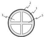
多層構造管は、筒状の非多孔質層2と、その内側に積層されてなる筒状の多孔質層1とからなる。多層構造管は、流体流入口と流体流出口とを有し、且つ流体流入口から流体流出口までを連通する反応管内腔3を有する。多層構造管の長手方向に直角に切断した面(横断面)は、例えば、円形、卵形、楕円形、長円形、角丸四角形、四角形などであることができ、耐圧性と軽量化との観点から、好ましくは円形である(例えば、図1参照)。多層構造管の内径および外径は、反応規模、強度、耐圧力などに応じて適宜設計できる。なお、内径および外径は、長手方向に直角な断面において、流体が流れている部分の面積をA、流体が管路と接している周の長さ(浸辺長)をLとするとき、4A/Lにて定義される値(相当径)である。なお、流体は、液体、気体または気液混合体、好ましくは気体である。 The multi-layer structure tube consists of a cylindrical
多孔質層は、多数の細孔の空いた構造の層である。多孔質層は、流体が一方から他方に通り抜けることができる細孔(連通孔)を有することが好ましい。多孔質層は、全てが連通孔である必要は無く、流体が入り込める細孔容積を有するものであれば、行き止まりの細孔であってもよい。多孔質層は、触媒の担体となる部分であるので、反応管において行う化学反応に応じて、金属製のもの、セラミックス製のものなどから、適宜、選定することができる。熱伝導性の観点から、多孔質層は、金属製が好ましい。 A porous layer is a layer having a structure with a large number of pores. The porous layer preferably has pores (communicating pores) through which fluid can pass from one side to the other. The porous layer does not need to have continuous pores, and may have dead-end pores as long as it has a pore volume into which a fluid can enter. Since the porous layer serves as a carrier for the catalyst, it can be appropriately selected from metals, ceramics, etc., depending on the chemical reaction to be performed in the reaction tube. From the viewpoint of thermal conductivity, the porous layer is preferably made of metal.
流体流入口側から流体流出口側までの範囲において多孔質層の厚さに分布を有する。厚さの分布は、例えば、対象の化学反応速度と空間速度との関係から、化学反応によって生じる温度分布を推測し、推測された温度分布において高温となりやすい部分の多孔質層の厚さを薄くすることが好ましい。より具体的に、流体流入口側よりも流体流出口側の方が高温になりやすい反応においては、流体流出口側よりも流体流入口側の方が厚くなるような分布にする。逆に、流体流出口側よりも流体流入口側の方が高温になりやすい反応においては、流体流入口側よりも流体流出口側の方が厚くなるような分布にする。多孔質層の厚さの分布は、連続的に変化する分布であってもよいし、段階的に変化する分布であってもよい。多孔質層の厚さの範囲は、特に制限されないが、例えば、0.1~2.0mmである。 The thickness of the porous layer has a distribution in the range from the fluid inlet side to the fluid outlet side. For the thickness distribution, for example, the temperature distribution caused by the chemical reaction is estimated from the relationship between the target chemical reaction rate and the space velocity, and the thickness of the porous layer is reduced in areas where the temperature is likely to become high in the estimated temperature distribution. preferably. More specifically, in a reaction in which the fluid outlet side tends to be hotter than the fluid inlet side, the distribution is such that the fluid inlet side is thicker than the fluid outlet side. Conversely, in a reaction in which the fluid inlet side tends to be hotter than the fluid outlet side, the distribution is such that the fluid outlet side is thicker than the fluid inlet side. The thickness distribution of the porous layer may be a continuously changing distribution or a stepwise changing distribution. Although the range of thickness of the porous layer is not particularly limited, it is, for example, 0.1 to 2.0 mm.
多孔質層における、相対密度、空隙率、開放気孔率、有効孔隙率、細孔径分布などは、反応管において行う化学反応に応じて、適宜、設定できる。例えば、多孔質層は、相対密度が、好ましくは20%~80%である。なお、相対密度(密度指数)は、次式にて定義される。
相対密度[%]=見かけ密度/真密度×100
なお、真密度は、固体自身が占める体積だけを密度算定用の体積とした場合の密度であり、金属バルクの密度を真密度として用いるか、又はピクノメーター法に基づいて算出できる。見かけ密度は、固体自身と内部空隙を体積とした場合の密度であり、アルキメデス法に基づいて算出できる。嵩密度は、固体自身、細孔および内部空隙を体積とした場合の密度のことであり、ノギスやマイクロメータなどを用いる寸法法に基づいて算出できる。The relative density, porosity, open porosity, effective porosity, pore size distribution, etc. of the porous layer can be appropriately set according to the chemical reaction to be performed in the reaction tube. For example, the porous layer preferably has a relative density of 20% to 80%. The relative density (density index) is defined by the following formula.
Relative density [%] = apparent density / true density x 100
The true density is the density when only the volume occupied by the solid itself is used as the volume for density calculation, and can be calculated using the density of the metal bulk as the true density or based on the pycnometer method. The apparent density is the density when the volume of the solid itself and internal voids is taken as the volume, and can be calculated based on the Archimedes method. Bulk density is the density of the solid itself, pores and internal voids as a volume, and can be calculated based on a dimensional method using a vernier caliper, micrometer, or the like.
非多孔質層は、連通孔を実質的に有しない、稠密な若しくは緻密な構造の層である。非多孔質層は、流体を実質的に遮断し、流体が漏れ出ないようにする。非多孔質層は、本発明の効果を奏する限り、層内部に封じ込められた空隙(内部空隙)を有していてもよい。例えば、非多孔質層は、相対密度が、好ましくは99%以上、最も好ましくは100%である。非多孔質層は、金属製のもの、セラミックス製のものなどから、適宜、選定することができる。熱伝導性の観点から、非多孔質層は、金属製が好ましい。
非多孔質層の厚さの範囲は、特に制限されないが、例えば、0.1~2.0mmである。非多孔質層の厚さに分布を持たせてもよい。例えば、多孔質層の厚さと非多孔質層の厚さとの合計が、流体流入口側から流体流出口側までの範囲において、実質的に一定であるようにすることができる。
また、熱膨張などの観点から、多孔質層と非多孔質層は、同じ材質のもので作製することが好ましい。A non-porous layer is a layer with a dense or dense structure that has substantially no communicating pores. The non-porous layer is substantially impervious to fluid and prevents fluid from escaping. The non-porous layer may have voids (internal voids) enclosed within the layer as long as the effects of the present invention are exhibited. For example, the non-porous layer preferably has a relative density of 99% or greater, most preferably 100%. The non-porous layer can be appropriately selected from metals, ceramics, and the like. From the viewpoint of thermal conductivity, the non-porous layer is preferably made of metal.
The thickness range of the non-porous layer is not particularly limited, but is, for example, 0.1 to 2.0 mm. The thickness of the non-porous layer may be distributed. For example, the sum of the thickness of the porous layer and the thickness of the non-porous layer can be made substantially constant in the range from the fluid inlet side to the fluid outlet side.
From the viewpoint of thermal expansion, etc., it is preferable that the porous layer and the non-porous layer are made of the same material.
多孔質層から非多孔質層までの細孔の割合の遷移は、ステップワイズであってもよいし、グラデーションであってもよい。また、非多孔質層の厚さに対する多孔質層の厚さの比は、好ましくは1/50~50/1、より好ましくは1/30~10/1、さらに好ましくは1/10~2/1である。 The pore ratio transition from the porous layer to the non-porous layer may be stepwise or gradational. The ratio of the thickness of the porous layer to the thickness of the non-porous layer is preferably 1/50 to 50/1, more preferably 1/30 to 10/1, and still more preferably 1/10 to 2/1. 1.
触媒は、前記の多孔質層に担持されている。触媒は、反応管において行う化学反応に応じて、適宜、選定することができる。例えば、二酸化炭素若しくは一酸化炭素のメタン化反応(メタネーション)においては、Ni系触媒、白金族金属系触媒、その他の貴金属系触媒等などを用いることができる。メタネーション触媒の具体例としては、ニッケルアルミネート(NiAlxOy)、Ru/NiAlxOy、Ru/Al2O3、Ru/TiO2、Ni/TiO2、Ru-Ni/TiO2などを挙げることができる。CO選択酸化触媒の具体例としては、Ru/Al2O3、Ru/C、Rhポルフィリン/C、Cox-Fe2O、Co3O4、Cu/CeO2-ZrO2、Ni/CeO2-ZrO2、Co/CeO2-ZrO2、Fe/CeO2-ZrO2、Pt/Al2O3、CuMn2O4、CuZnO、Pt/SiO2,Pd/Al2O3、Pt/SnO2、Pd/CeO2、Pt/TiO2、PdCl2-CuCl2/C、Au/TiO2、Au/Fe2O3などを挙げることができる。A catalyst is supported on the porous layer. A catalyst can be appropriately selected according to the chemical reaction to be performed in the reaction tube. For example, in the methanation reaction (methanation) of carbon dioxide or carbon monoxide, Ni-based catalysts, platinum group metal-based catalysts, other noble metal-based catalysts, and the like can be used. Specific examples of methanation catalysts include nickel aluminate (NiAlx Oy ), Ru/NiAlx Oy , Ru/Al2 O3 , Ru/TiO2 , Ni/TiO2 , Ru—Ni/TiO2 and the like. can be mentioned. Specific examples of CO selective oxidation catalysts include Ru/Al2 O3 , Ru/C, Rh porphyrin/C, Cox —Fe2 O, Co3 O4 , Cu/CeO2 —ZrO2 and Ni/CeO2 .-ZrO2 , Co/CeO2- ZrO2, Fe/CeO2- ZrO2, Pt/Al2O3,CuMn2O4 ,CuZnO , Pt/SiO2 , Pd/Al2O3,Pt /SnO2 , Pd/CeO2 , Pt/TiO2 , PdCl2 —CuCl2 /C, Au/TiO2 , Au/Fe2 O3 and the like.
多孔質層への触媒の担持は、その手法において、特に制限されない。例えば、触媒を構成する成分(触媒成分)の水溶液または分散液を多孔質層に接触させることによって、担持することができる。触媒成分の水溶液または分散液の多孔質層への接触は、触媒成分の水溶液または分散液に多孔質層を具備する反応管を浸漬する方法、多孔質層を具備する反応管に触媒成分の水溶液または分散液を流す方法、などによって行うことができる。接触させた後に、必要に応じて、熱処理(例えば、乾燥、焼成など)を施すことができる。 There are no particular restrictions on the method of supporting the catalyst on the porous layer. For example, the catalyst can be supported by contacting the porous layer with an aqueous solution or dispersion of the component that constitutes the catalyst (catalyst component). Contacting the porous layer with the aqueous solution or dispersion of the catalyst component can be done by immersing the reaction tube having the porous layer in the aqueous solution or dispersion of the catalyst component, or by immersing the reaction tube with the porous layer in the aqueous solution of the catalyst component. Alternatively, it can be carried out by a method of flowing a dispersion liquid, or the like. After contacting, a heat treatment (eg, drying, baking, etc.) can be applied, if desired.
本発明の反応管の他の一態様は、筒状の多孔質層の内面から反応管内腔に向かって凸に設けられた板状の多孔質層4をさらに有する(例えば、図4)。板状の多孔質層の形状は、特に制限されない。例えば、本発明の反応管の他の一の態様は、板状の多孔質層5が、十字状の形を成している(例えば、図5)。本発明の反応管の他の一の態様は、板状の多孔質層が、らせん状の形を成している。板状の多孔質層は、流体の流れの制御、触媒の担持量の増加、流体と多孔質層との接触面積の増加などに寄与する。 Another embodiment of the reaction tube of the present invention further has a plate-like
本発明の反応管の他の一の態様は、多層構造管の外面から外側に向かって凸に設けられたプレートフィン11をさらに有する。プレートフィンは、多層構造管の長手方向に対して板面が平行になるように設けてもよいし、板面がらせん状になるように設けてもよいし、多層構造管の長手方向に対して板面が非平行(例えば、直角など)になるように設けてもよい。 Another embodiment of the reaction tube of the present invention further has
本発明の反応管の他の一の態様は、多層構造管の外面から外側に向かって凸に設けられたプレートフィンの端が隣接する別の多層構造管の外面に繋がっている。例えば、図8に示すように、多層構造管(反応管10)の長手方向に対して板面が平行になるようにプレートフィン11を設け、そのプレートフィン11の端が隣接する別の多層構造管(反応管10)の外面に繋がっている。これによって、反応管の振動の抑制、伝熱媒体の流れ制御、反応熱の放出促進などを行うことができる。プレートフィン11による連結の態様は、特に限定されず、図8に示すような同心円状としてもよいし、放射状としてもよいし、格子状としてもよい。
反応管10が伝熱媒体管12の内面に隣接している場合は、多層構造管(反応管10)の外面から外側に向かって凸に設けられたプレートフィンの端が伝熱媒体管の内面に繋がっていてもよい。また、熱膨張などの観点から、プレートフィンは、反応管と同じ材質のもので作製することが好ましい。In another aspect of the reaction tube of the present invention, the ends of plate fins projecting outward from the outer surface of the multilayer structure tube are connected to the outer surface of another adjacent multilayer structure tube. For example, as shown in FIG. 8,
When the
プレートフィンは、穴の無い板状のものであってもよいし、穴の開いた板状のものであってもよい。穴の開いた板状のものは、当該穴によって伝熱媒体の流れの制御、デッドスペースの低減、伝熱媒体との接触面積の増加などに寄与することができる。穴は、楕円形に限らず、様々な形状とすることができ、目的に応じて適宜な場所に設けることができる。また、プレートフィンは、非多孔質のもので作製してもよいし、多孔質のもので作製してもよい。 The plate fins may be plate-like without holes or plate-like with holes. A perforated plate can contribute to controlling the flow of the heat transfer medium, reducing dead space, and increasing the contact area with the heat transfer medium. The hole is not limited to an elliptical shape, and can be formed in various shapes, and can be provided at an appropriate location depending on the purpose. Also, the plate fins may be made of non-porous material or may be made of porous material.
本発明の触媒反応装置若しくは気相触媒反応装置は、本発明の反応管と伝熱媒体管とを含有する反応器、を具備する。 The catalytic reactor or gas-phase catalytic reactor of the present invention comprises a reactor containing the reaction tube of the present invention and a heat transfer medium tube.
本発明に用いられる反応器の一態様は、反応管を複数有することが好ましい。各反応管は、その長手方向が、伝熱媒体管の長手方向に平行になるように配置されていることが好ましい。また、各反応管は、隣接する別の反応管とプレートフィンを介して相互に連結されていてもよい。複数の反応管は、すべてが本発明の反応管であってもよいし、一部が本発明の反応管であってもよいが、すべてが本発明の反応管であることが好ましい。 One aspect of the reactor used in the present invention preferably has a plurality of reaction tubes. Each reaction tube is preferably arranged such that its longitudinal direction is parallel to the longitudinal direction of the heat transfer medium tube. Also, each reaction tube may be interconnected with another adjacent reaction tube via plate fins. The plurality of reaction tubes may all be the reaction tubes of the present invention, or some of them may be the reaction tubes of the present invention, but all are preferably the reaction tubes of the present invention.
伝熱媒体管12は、伝熱媒体流入口16と伝熱媒体流出口17とを有し且つ伝熱媒体流入口から伝熱媒体流出口までを連通する伝熱媒体管内腔13を有する管である。伝熱媒体管の長手方向に直角に切断した面は、例えば、円形、卵形、楕円形、長円形、角丸四角形、四角形などであることができる。耐圧性と軽量化との観点から、円形が好ましい。 The heat
そして、本発明に用いられる反応器は、流体流入口にて流体状原料が反応管内腔に流入し、反応管内腔にて流体状原料を触媒と接触させて化学反応させ、流体流出口にて反応管内腔から前記化学反応で得られる流体状生成物を含む流体混合物が流出する、機構、および伝熱媒体流入口にて伝熱媒体が伝熱媒体管内腔に流入し、伝熱媒体流出口にて第一伝熱媒体管内腔から伝熱媒体が流出する、機構を有し、且つ反応管が伝熱媒体管内腔に挿通されていて、伝熱媒体管内腔内の伝熱媒体が反応管壁を介して反応管内腔内のものとの間で熱交換する、機構を有する。 In the reactor used in the present invention, the fluid raw material flows into the reaction tube lumen at the fluid inlet, the fluid raw material is brought into contact with the catalyst in the reaction tube lumen and chemically reacts, and at the fluid outlet a mechanism through which a fluid mixture containing a fluid product obtained by the chemical reaction flows out from the reaction tube lumen, and a heat transfer medium inlet at which the heat transfer medium flows into the heat transfer medium tube lumen, and a heat transfer medium outlet at the heat transfer medium inlet; The heat transfer medium flows out from the first heat transfer medium tube lumen at and the reaction tube is inserted into the heat transfer medium tube lumen, and the heat transfer medium in the heat transfer medium tube lumen is the reaction tube It has a mechanism for exchanging heat through the wall with that within the reactor tube lumen.
流体流入口10aは伝熱媒体流入口16または伝熱媒体流出口17と区別されており、流体流入口にて流体状原料が反応管内腔に流入する。流体流入口と伝熱媒体流入口または伝熱媒体流出口との区別は、例えば、反応管の流体流入口側の端部を保持する板25によって行うことができる。 The
反応器の上流には、流体状原料を調製するための装置、例えば、流体状原料を構成する各成分を所定の割合で混ぜ合わせるための混合機構や、流体状原料を構成する各成分を貯蔵するためのタンクや、コンプレッサ31、熱交換器32などを設置することができる。原料が、液化二酸化炭素のように液体となっている場合には、安全に気化させるなどのために、気化器34などを設けることができる。流体状原料を構成する成分は反応器で行う化学反応に応じて適宜選択でき、例えば、二酸化炭素のメタン化反応に用いられる流体状原料は、水素ガスと二酸化炭素ガスとを少なくとも含むものである。反応管内腔への流体状原料の流入量は、反応器で行う化学反応に応じて適宜設定できる。 Upstream of the reactor, a device for preparing the fluid raw material, for example, a mixing mechanism for mixing each component constituting the fluid raw material at a predetermined ratio, and a storage of each component constituting the fluid raw material A tank for heating, a
伝熱媒体流入口にて伝熱媒体が伝熱媒体管内腔13に流入する。伝熱媒体は、所望の化学反応を行うための温度範囲において変質せず、流動性を維持できるものであれば、特に限定されない。伝熱媒体の具体例としては、グリセリン、ポリグリコールなどの多価アルコール類; アニソール、ジフェニルエーテル、フェノールなどのフェノ-ルおよびフェノール性エーテル; ターフェニルなどのポリフェニル類、o-ジクロルベンゼン、ポリクロルポリフェニルなどの塩素化ベンゼンおよびポリフェニル; テトラアリルケイ酸塩などのケイ酸エステル類; ナフタレン誘導体、鉱油などの分留タールおよび石油類; 硝酸ナトリウム、亜硝酸ナトリウム、硝酸カリウムなどの硝酸塩および亜硝酸塩(Heat Transfer Salt); シリコーン類; フッ素化合物; グリコール類; Na金属、K金属、Pb金属、Pb-Bi共融混合物、Na-K合金などの融解金属および合金; などを挙げることができる。
伝熱媒体管内腔13を流れる伝熱媒体の圧力、および反応管内腔3を流れるものの圧力は、特に制限されないが、熱伝達性の観点から非多孔質層の厚さを薄くするために、両圧力の差が、非多孔質層の耐圧強度を下回るようにすることが好ましい。The heat transfer medium flows into the heat transfer
The pressure of the heat transfer medium flowing through the heat transfer
伝熱媒体流入口と伝熱媒体流出口とは、その配置において、特に制限されないが、伝熱媒体が反応管の長手方向に対して直角な方向で流れやすくするように、配置することが好ましい。伝熱媒体管の内面の左右から交互に仕切板を設けて、伝熱媒体の流れを蛇行させることができる。また、伝熱媒体管の内面に沿ってらせん状に仕切板を設けて、伝熱媒体の流れを旋回させることができる。なお、仕切板は、反応管の中間部を保持するように反応管が貫通可能な穴を有してもよい。 The heat transfer medium inlet and the heat transfer medium outlet are not particularly limited in their arrangement, but are preferably arranged so that the heat transfer medium can easily flow in a direction perpendicular to the longitudinal direction of the reaction tube. . Partition plates can be provided alternately from the left and right sides of the inner surface of the heat transfer medium tube to cause the flow of the heat transfer medium to meander. Further, a spiral partition plate can be provided along the inner surface of the heat transfer medium tube to swirl the flow of the heat transfer medium. The partition plate may have a hole through which the reaction tube can pass so as to hold the intermediate portion of the reaction tube.
流体流出口10bは伝熱媒体流入口16または伝熱媒体流出口17と区別されており、流体流出口にて流体状生成物を含む流体混合物が反応管内腔3から流出する。流体流出口と伝熱媒体流入口または伝熱媒体流出口との区別は、例えば、反応管の流体流出口側の端部を保持する板26によって行うことができる。伝熱媒体流出口にて伝熱媒体が伝熱媒体管内腔から流出する。流出した伝熱媒体はリサイクルすることができる。 The
流体流出口にて流出する流体混合物は、流体状生成物以外に、未反応の流体状原料、流体状副生物などを含むことがある。例えば、二酸化炭素のメタン化反応で得られる、流体状生成物はメタンであり、流体状副生成物は水である。 The fluid mixture discharged from the fluid outlet may contain unreacted fluid raw materials, fluid by-products, etc. in addition to the fluid product. For example, the fluid product obtained in the methanation reaction of carbon dioxide is methane, and the fluid by-product is water.
反応管10は伝熱媒体管内腔13に挿通されていて、伝熱媒体管内腔内の伝熱媒体が反応管の非多孔質層および多孔質層を介して反応管内腔3内の流体との間で熱交換することができる。熱交換の効率の観点から、反応管は、反応管壁の内側面から内に向かって突き出した板状の多孔質層を有することが好ましい。また、反応管は、反応管壁の外側面から外に向かって突き出したプレートフィンを有することが好ましい。 The
一般に、管型反応器においては、反応管の流れ方向の温度分布が不均一になりやい。発熱量の多い化学反応においてはホットスポットが発生することもある。ホットスポットの発生を抑制し、反応管の流れ方向の温度分布を均一化することが望まれる。
伝熱媒体流入口をホットスポットが発生するおそれのある部分に近い位置に設置したり、仕切板によって伝熱媒体管内腔を分割し、分割されたそれぞれに伝熱媒体流入口および伝熱媒体流出口を設け、分割された伝熱媒体管内腔に流す伝熱媒体のそれぞれの温度を、ホットスポットが発生するおそれのある部分に近い側において、相対的に低くしたりすることができる。また、プレートフィンをホットスポットが発生するおそれのある部分の近辺に多めに設け、その部分における熱移動量を増やすことによって、反応管の流れ方向の温度分布を均一化することができる。プレートフィンは、触媒の置かれた範囲のうち流体流入口に近い側の部分だけに設けられていてもよいし、触媒の置かれた範囲のうち流体流出口に近い側の部分だけに設けられていてもよいし、触媒の置かれた範囲の全部に設けられていてもよい。Generally, in a tubular reactor, the temperature distribution in the flow direction of the reaction tube tends to be uneven. Hot spots can also occur in highly exothermic chemical reactions. It is desired to suppress the generation of hot spots and to uniform the temperature distribution in the flow direction of the reaction tube.
Place the heat transfer medium inlet close to the part where hot spots may occur, or divide the heat transfer medium tube lumen with a partition plate and separate the heat transfer medium inlet and the heat transfer medium flow into each of the divided sections. An outlet may be provided to lower the temperature of each of the heat transfer medium flowing through the split heat transfer medium tube lumens closer to where hot spots may occur. In addition, by providing a large number of plate fins in the vicinity of a portion where hot spots are likely to occur and increasing the amount of heat transfer in that portion, the temperature distribution in the flow direction of the reaction tube can be made uniform. The plate fins may be provided only in a portion of the area where the catalyst is placed, which is closer to the fluid inlet, or provided only in a portion of the area where the catalyst is placed, which is closer to the fluid outlet. It may be provided over the entire area where the catalyst is placed.
本発明の触媒反応装置若しくは気相触媒反応装置は、それの製造方法によって特に限定されない。たとえば、反応管および伝熱媒体管ならびに付属物をそれぞれ用意し、それらを溶接、螺合などによって組み立てることで、製造することができる。 The catalytic reactor or gas-phase catalytic reactor of the present invention is not particularly limited by its manufacturing method. For example, it can be manufactured by preparing a reaction tube, a heat transfer medium tube, and accessories, respectively, and assembling them by welding, screwing, or the like.
複雑な形状を有する反応管、伝熱媒体管、付属物または反応器は、それらの3Dデータに基づいて、その断面形状を積層していくことでひと塊の立体物として形成することを含む方法で、製造することができる。 A method for forming a reaction tube, a heat transfer medium tube, an appendage or a reactor having a complicated shape as a single three-dimensional object by layering the cross-sectional shape based on 3D data thereof. and can be manufactured.
3Dデータは、目的部品の3D形状データであってもよい。3DCADにて3D形状データを設計することができる。3Dデータは、3D形状データを変換して得られる、例えば、STL(Stereolithography)データであってもよい。STLデータは、3次元の立体形状を小さな三角形(ポリゴン)の集合体で表現するものである。 The 3D data may be 3D shape data of the target part. 3D shape data can be designed with 3D CAD. The 3D data may be, for example, STL (Stereolithography) data obtained by converting 3D shape data. The STL data expresses a three-dimensional solid shape with an aggregate of small triangles (polygons).
断面形状の積層による立体物の形成(造形)は、パウダーベッドフュージョン(PBF)法、メタルデポジッション法、材料押出堆積(FDM)法、液体金属インクジェット法、バインダージェット法、PBFによる積層造形中に切削を行うハイブリッド法などで行うことができる。これらのうち、パウダーベッドフュージョン(PBF)法、またはメタルデポジッション法が好ましい。 Formation (modeling) of a three-dimensional object by lamination of cross-sectional shapes is performed by the powder bed fusion (PBF) method, metal deposition method, material extrusion deposition (FDM) method, liquid metal inkjet method, binder jet method, and laminate molding by PBF. It can be performed by a hybrid method of cutting. Among these, the powder bed fusion (PBF) method and the metal deposition method are preferred.
パウダーベッドフュージョン法は、材料粉末を敷き詰め、熱源となるレーザや電子ビームで造形する部分を溶融・凝固させる方法である。材料粉末を敷き詰め、溶融・凝固を繰り返すことで造形する。造形終了後には、固化していない粉末を取り除いて造形物を取り出す。 The powder bed fusion method is a method in which material powder is spread and the part to be shaped is melted and solidified by a laser or electron beam as a heat source. It is shaped by spreading material powder and repeating melting and solidification. After the molding is finished, the unsolidified powder is removed and the molded object is taken out.
パウダーベッドフュージョン法には、レーザビーム熱源方式、電子ビーム熱源方式などがある。 The powder bed fusion method includes a laser beam heat source method, an electron beam heat source method, and the like.
パウダーベッド・レーザビーム熱源方式は、敷き詰められた材料粉末にレーザビームを照射して、溶融・凝固または焼結させて積層造形する。レーザビーム熱源方式は、通常、窒素などの不活性雰囲気中で溶融凝固がなされる。レーザビーム熱源方式はレーザを照射する際の位置決めをミラーの角度を変えて行う。 In the powder bed/laser beam heat source method, a laser beam is applied to a spread material powder to melt, solidify, or sinter the material for lamination molding. In the laser beam heat source method, melting and solidification are usually performed in an inert atmosphere such as nitrogen. In the laser beam heat source method, positioning is performed by changing the angle of the mirror when irradiating the laser.
パウダーベッド・電子ビーム熱源方式は、敷き詰められた材料粉末に電子ビームを高真空中で照射し衝突させることで、運動エネルギーを熱に変換し粉末を溶融させる電子ビーム熱源方式は、通常、真空中で溶融凝固がなされる。電子ビーム熱源方式は、磁界によるレンズを用いて電子ビームの向きを変える。その結果、電子ビーム熱源方式は、高速な位置決めが可能である。 The powder bed/electron beam heat source method irradiates and collides an electron beam in a high vacuum with the powder bed and electron beam heat source method, which converts the kinetic energy into heat and melts the powder. Melt and solidify at The electron beam heat source method uses a lens with a magnetic field to change the direction of the electron beam. As a result, the electron beam heat source system is capable of high-speed positioning.
メタルデポジッション法は、溶融した金属材料を所定の場所に積層・凝固させて造形する方法である。メタルデポジッション方法は、造形終了後のパウダー除去の作業を要しない。 The metal deposition method is a method of forming a model by layering and solidifying a molten metal material at a predetermined location. The metal deposition method does not require powder removal work after completion of modeling.
メタルデポジッション法には、金属粉末を材料とするレーザビーム熱源方式、合金ワイヤを材料とするアーク放電方式などがある。 The metal deposition method includes a laser beam heat source method using metal powder as a material, an arc discharge method using an alloy wire as a material, and the like.
メタルデポジッション・レーザビーム熱源方式は、ノズルから金属粉末を噴射すると同時にレーザ光を照射することで金属粉末を溶融池に供給、凝固させて造形を行う。溶融ノズルまたはステージを移動させることによって立体形状を描く。金属粉の供給経路を切り替えることで、異種金属の造形ができる。レーザ出力が大きいので、高速造形に適する。 In the metal deposition/laser beam heat source method, metal powder is injected from a nozzle and irradiated with a laser beam at the same time to supply the metal powder to the molten pool and solidify it for modeling. Three-dimensional shapes are drawn by moving the melt nozzle or stage. Different metals can be shaped by switching the supply route of the metal powder. The laser output is large, so it is suitable for high-speed molding.
メタルデポジッション・アーク放電方式は、金属ワイヤ先端のアーク放電により金属ワイヤを溶融し、これを積層することによって造形する。装置価格や材料費が比較的安く、高速造形ができる。 In the metal deposition/arc discharge method, the metal wire is melted by arc discharge at the tip of the metal wire, and the metal wire is laminated to form a model. Equipment and material costs are relatively low, and high-speed modeling is possible.
造形の後、応力緩和、強度向上などのために、熱処理することができる。熱処理における、温度、時間、雰囲気などの条件は、使用する金属材料などに応じて適宜設定できる。 After shaping, heat treatment can be performed for stress relaxation, strength improvement, and the like. Conditions such as temperature, time and atmosphere in the heat treatment can be appropriately set according to the metal material to be used.
本発明の反応管の製造方法の具体的な一形態は、敷き詰めた材料粉末に、多孔質層に対応する部分への照射よりも非多孔質層に対応する部分への照射が強くなるように、レーザまたは電子ビームを照射して焼結させることによって、環状の非多孔質層と、その内側に積層されてなる環状の多孔質層とからなる多層構造板を形成することを繰り返して、筒状の非多孔質層と、その内側に積層されてなる筒状の多孔質層とからなり、流体流入口と流体流出口とを有し、且つ流体流入口から流体流出口までを連通する反応管内腔を有する、多層構造管を得ること、および多孔質層に、触媒を担持させることを含む。材料粉末としては、金属の粉末;酸化物、炭化物、窒化物、ホウ化物などの無機化合物の粉末などを用いることができる。 In one specific embodiment of the method for manufacturing a reaction tube of the present invention, the material powder spread is arranged so that the portion corresponding to the non-porous layer is irradiated more strongly than the portion corresponding to the porous layer. , by sintering by irradiating with a laser or an electron beam, a multilayer structure plate composed of an annular non-porous layer and an annular porous layer laminated inside thereof is repeatedly formed. A non-porous layer having a non-porous shape and a cylindrical porous layer laminated inside thereof, having a fluid inlet and a fluid outlet, and communicating from the fluid inlet to the fluid outlet It includes obtaining a multi-layer structure tube having a tube lumen and supporting a catalyst on the porous layer. As material powders, metal powders; powders of inorganic compounds such as oxides, carbides, nitrides and borides can be used.
本発明の流体状生成物を得るための方法は、本発明の触媒反応装置において、流体状原料を流体流入口にて反応管内腔に供給すること、伝熱媒体を伝熱媒体流入口にて伝熱媒体管内腔に供給し、伝熱媒体管内腔に流し且つ伝熱媒体管内腔から伝熱媒体流出口にて排出することによって、反応管内腔内のものの温度を制御しながら化学反応を行うこと、反応管内腔から流体流出口にて前記化学反応で得られる流体状生成物を含む流体混合物を排出すること、を含む。 The method for obtaining the fluid product of the present invention comprises, in the catalytic reaction apparatus of the present invention, supplying a fluid raw material into the reaction tube lumen at the fluid inlet, and supplying a heat transfer medium at the heat transfer medium inlet. A chemical reaction is carried out while controlling the temperature of things in the reaction tube lumen by supplying the heat transfer medium tube lumen, flowing it into the heat transfer medium tube lumen, and discharging the heat transfer medium tube lumen from the heat transfer medium tube lumen at the heat transfer medium outlet. and discharging a fluid mixture containing fluid products obtained from the chemical reaction from the reaction tube lumen at a fluid outlet.
CO(一酸化炭素)、メタノールまたはメタンの製造方法においては、流体状原料として、CO2(二酸化炭素)とH2(水素)を含むガスを使用し、CO2の還元反応を行う。
流入させるCO2とH2を含むガスの量は、反応速度、反応管内腔の容量などに応じて、適宜設定できる。
CO2とH2との比率によって、CO2の還元反応は次のように進行する。
CO2 + H2 → CO + H2O
CO2 + 3H2 → CH3OH + H2O
CO2 + 4H2 → CH4 + 2H2OIn a method for producing CO (carbon monoxide), methanol, or methane, a gas containing CO2 (carbon dioxide) and H2 (hydrogen) is used as a fluid raw material, and CO2 is reduced.
The amount of gas containing CO2 and H2 to be introduced can be appropriately set according to the reaction rate, the capacity of the reaction tube lumen, and the like.
Dependingon the ratio ofCO2 and H2, the reduction reaction ofCO2 proceeds as follows.
CO2 +H2→CO+H2O
CO2 + 3H2 ->CH3OH+H2O
CO2 +4H2 -> CH4+2H2O
本発明の触媒反応装置および流体状生成物を得るための方法は、CO2(二酸化炭素)とH2(水素)を含むガスからCO(一酸化炭素)、メタノールまたはメタンを製造する方法以外のC1化学合成法などにも好ましく用いることができる。C1化学合成法として、例えば、メタンと水(水蒸気)との反応で一酸化炭素と水素とを製造する方法、メタンと二酸化炭素との反応で一酸化炭素と水素とを製造する方法、一酸化炭素と水との反応で二酸化炭素と水素とを製造する方法、メタンと水との反応で二酸化炭素と水素とを製造する方法、一酸化炭素と水素との反応でメタンと二酸化炭素を製造する方法、一酸化炭素と水素との反応でメタノールを製造する方法、一酸化炭素と水素との反応でアセトンと水を製造する方法、メタンと酸素との反応で一酸化炭素と水素、エチレンと水、またはメタノールを製造する方法などを挙げることができる。The catalytic reactor and the method for obtaining fluid products of the present invention are other than the method of producing CO (carbon monoxide), methanol or methane from a gas containing CO2 (carbon dioxide) and H2 (hydrogen). It can also be preferably used for the C1 chemical synthesis method and the like. Examples of C1 chemical synthesis methods include a method of producing carbon monoxide and hydrogen by reacting methane and water (steam), a method of producing carbon monoxide and hydrogen by reacting methane and carbon dioxide, and a method of producing carbon monoxide and hydrogen by reacting methane and carbon dioxide. A method for producing carbon dioxide and hydrogen by reacting carbon and water, a method for producing carbon dioxide and hydrogen by reacting methane and water, and a method for producing methane and carbon dioxide by reacting carbon monoxide and hydrogen a method for producing methanol by reacting carbon monoxide and hydrogen; a method for producing acetone and water by reacting carbon monoxide and hydrogen; a method for producing acetone and water by reacting carbon monoxide and hydrogen; , or a method for producing methanol.
本発明においては、CO2の還元反応により得られる生成物(CO(一酸化炭素)、メタノールまたはメタン)ならびに未反応物(主にCO2)を、分離精製することができる。分離精製法としては、膜分離法、吸着分離法、吸収分離法、蒸留分離法、深冷分離法等を挙げることができる。メタンの分離精製においては、膜分離法が、分離選択性、分離速度、安価でコンパクトな設備という観点から好ましい。メタンの分離精製において得られる未反応物(主にCO2)と低濃度のメタンは、上記メタンの製造方法における流体状原料として使用することができる。一酸化炭素は人体に対し有毒であるので、一酸化炭素濃度が30ppm以下となるように、処理することが好ましい。一酸化炭素濃度を下げる方法としては、例えば、COメタネーション反応で一酸化炭素をメタンに転化する、CO選択酸化反応で一酸化炭素を二酸化炭素に転化する、吸着剤や吸収剤などによって二酸化炭素を吸着または吸収する、などを挙げることができる。In the present invention, products (CO (carbon monoxide), methanol or methane) obtained by reduction reaction of CO2 and unreacted substances (mainly CO2 ) can be separated and purified. Examples of separation and purification methods include a membrane separation method, an adsorption separation method, an absorption separation method, a distillation separation method, a cryogenic separation method, and the like. In the separation and purification of methane, the membrane separation method is preferable from the viewpoint of separation selectivity, separation speed, and inexpensive and compact equipment. Unreacted substances (mainly CO2 ) and low-concentration methane obtained in the separation and purification of methane can be used as fluid raw materials in the above-described method for producing methane. Since carbon monoxide is toxic to the human body, it is preferable to treat it so that the concentration of carbon monoxide is 30 ppm or less. Methods for reducing the concentration of carbon monoxide include, for example, converting carbon monoxide into methane by a CO methanation reaction, converting carbon monoxide into carbon dioxide by a CO selective oxidation reaction, and using an adsorbent or absorbent to convert carbon monoxide into carbon dioxide. can be exemplified by adsorbing or absorbing the
また、分離精製によって得られるメタンを燃料としてガスタービンに供給することができる。このガスタービンにより発電することができる。
ガスタービンからの燃焼排ガスは、通常、二酸化炭素を含むので、これを上記メタンの製造方法における流体状原料として使用することができる。In addition, methane obtained by separation and refinement can be supplied to gas turbines as fuel. Electric power can be generated by this gas turbine.
Since flue gas from gas turbines usually contains carbon dioxide, it can be used as a fluid feedstock in the methane production process described above.
本発明は、各種の化学反応において使用することができる。本発明は、水の電気分解などにて生成する水素の活用、人や動物の呼吸によって若しくは燃料などの燃焼によって生成する二酸化炭素の活用、水の製造、または燃料などとしてのメタンの製造において、有用である。本発明は、宇宙ステーション、宇宙船、ロケットなどにおいても、利用できる。 The present invention can be used in various chemical reactions. The present invention utilizes hydrogen produced by electrolysis of water, etc., utilizes carbon dioxide produced by breathing of humans and animals or by burning fuel, produces water, or produces methane as fuel. Useful. The invention can also be used in space stations, spacecraft, rockets, and the like.
本発明は、上述のような特徴を具備するものであれば、計装、管、槽、塔などの化学工学上の各種機器を具備することができる。また、本発明の主旨を逸脱しない限り、変更、置換、追加、省略をしたものも、本発明の権利範囲に包含されることが、当業者において理解される。 The present invention can be provided with various chemical engineering devices such as instrumentation, pipes, tanks, towers, etc., as long as they have the features described above. In addition, those skilled in the art will understand that changes, replacements, additions, and omissions are included in the scope of the present invention as long as they do not depart from the gist of the present invention.
1:筒状の多孔質層
2:筒状の非多孔質層
3:反応管内腔
4,5,6,:板状の多孔質層
10:反応管
10a:反応管流体流入口
10b:反応管流体流出口
11:プレートフィン
12:伝熱媒体管
16:伝熱媒体流入口
17:伝熱媒体流出口
13:伝熱媒体管内腔
20:反応器
9a:反応器流体流入口
9b:反応器流体流出口
25:流体流入口側保持板
26:流体流出口側保持板
30:触媒反応装置
31:圧縮機
32:熱交換器
34:気化器
35:熱交換器
38:気液分離器
21:液体流出管
39:気体流出管1: Cylindrical porous layer
2: Cylindrical non-porous layer
3: reaction tube lumen
4,5,6,: Plate-like porous layer
10: reaction tube
10a: Reactor tube fluid inlet
10b: Reactor tube fluid outlet
11: Plate fin
12: Heat transfer medium tube
16: Heat transfer medium inlet
17: heat transfer medium outlet
13: heat transfer medium tube lumen
20: Reactor
9a: Reactor fluid inlet
9b: reactor fluid outlet
25: Retaining plate on fluid inlet side
26: Retaining plate on fluid outlet side
30: Catalytic reactor
31: Compressor
32: Heat Exchanger
34: Vaporizer
35: Heat Exchanger
38: Gas-liquid separator
21: liquid outflow tube
39: gas outflow pipe
Claims (10)
Translated fromJapanese多孔質層に担持された触媒とを、
具備してなる、反応管。A reaction tube lumen comprising a cylindrical non-porous layer and a cylindrical porous layer laminated inside thereof, having a fluid inlet and a fluid outlet, and communicating from the fluid inlet to the fluid outlet. and having a distribution of the thickness of the porous layer in the range from the fluid inlet side to the fluid outlet side;
a catalyst supported on the porous layer,
A reaction tube.
各反応短管は、筒状の非多孔質層およびその内側に積層されてなる筒状の多孔質層からなり、流体流入口と流体流出口とを有し、且つ流体流入口から流体流出口までを連通する反応短管内腔を有する、多層構造管と、多孔質層に担持された触媒とを、具備してなり、
一つの反応短管の流体流出口が他の一つの反応短管の流体流入口にそれぞれの反応短管内腔が連通するように直列に接続されており、
1つの反応短管の多孔質層の厚さが、別の一つの反応短管の多孔質層の厚さと、実質的に相違する、
反応管。Consisting of two or more reaction short tubes,
Each short reaction tube is composed of a cylindrical non-porous layer and a cylindrical porous layer laminated inside thereof, and has a fluid inlet and a fluid outlet, and from the fluid inlet to the fluid outlet. comprising a multi-layer structure tube having a short reaction tube lumen that communicates with and a catalyst supported on a porous layer,
the fluid outlet of one reaction short tube is connected in series with the fluid inlet of another reaction short tube so that the lumen of each reaction short tube communicates;
the thickness of the porous layer of one reaction short tube is substantially different from the thickness of the porous layer of another reaction short tube;
reaction tube.
伝熱媒体流入口と伝熱媒体流出口とを有し且つ伝熱媒体流入口から伝熱媒体流出口までを連通する伝熱媒体管内腔を有する伝熱媒体管とを含有し、
流体流入口にて流体状原料が反応管内腔に流入し、反応管内腔にて流体状原料を触媒と接触させて化学反応させ、流体流出口にて反応管内腔から前記化学反応で得られる流体状生成物を含む流体混合物が流出する、機構、
伝熱媒体流入口にて伝熱媒体が伝熱媒体管内腔に流入し、伝熱媒体流出口にて第一伝熱媒体管内腔から伝熱媒体が流出する、機構、および
反応管が伝熱媒体管内腔に挿通されていて、伝熱媒体管内腔内の伝熱媒体が反応管壁を介して反応管内腔内のものとの間で熱交換する、機構を有する、
反応器を具備する、
触媒反応装置。a reaction tube according to any one of claims 1 to 5;
a heat transfer medium tube having a heat transfer medium inlet and a heat transfer medium outlet and having a heat transfer medium tube lumen communicating from the heat transfer medium inlet to the heat transfer medium outlet;
The fluid raw material flows into the reaction tube lumen through the fluid inlet, the fluid raw material is brought into contact with the catalyst in the reaction tube lumen and undergoes a chemical reaction, and the fluid obtained by the chemical reaction flows out of the reaction tube lumen through the fluid outlet. a mechanism, through which a fluid mixture containing the product flows out;
A mechanism in which a heat transfer medium flows into a heat transfer medium tube lumen at a heat transfer medium inlet and a heat transfer medium flows out from a first heat transfer medium tube lumen at a heat transfer medium outlet, and a mechanism inserted through the medium tube lumen, wherein the heat transfer medium in the heat transfer medium tube lumen exchanges heat with that in the reaction tube lumen through the reaction tube wall;
comprising a reactor,
Catalytic reactor.
流体状原料を流体流入口にて反応管内腔に供給すること、
伝熱媒体を伝熱媒体流入口にて伝熱媒体管内腔に供給し、伝熱媒体管内腔に流し且つ伝熱媒体管内腔から伝熱媒体流出口にて排出することによって、反応管内腔内のものの温度を制御しながら化学反応を行うこと、
反応管内腔から流体流出口にて前記化学反応で得られる流体状生成物を含む流体混合物を排出すること
を含む、
流体状生成物を得るための方法。In the catalytic reaction device according to claim 6 or 7,
supplying a fluid raw material into the reaction tube lumen at the fluid inlet;
By supplying the heat transfer medium to the heat transfer medium tube lumen at the heat transfer medium inlet, flowing it into the heat transfer medium tube lumen, and discharging it from the heat transfer medium tube lumen at the heat transfer medium outlet, conducting a chemical reaction while controlling the temperature of
discharging a fluid mixture containing a fluid product obtained by the chemical reaction from the reaction tube lumen at a fluid outlet;
A method for obtaining a fluid product.
多孔質層に、触媒を担持させることを含む、
請求項1~5のいずれかひとつに記載の反応管の製造方法。The spread material powder is irradiated with a laser or an electron beam so that the portion corresponding to the non-porous layer is irradiated more strongly than the portion corresponding to the porous layer, thereby sintering to form an annular shape. and a circular porous layer laminated on the inner side of the non-porous layer, and a cylindrical non-porous layer laminated on the inner side of the cylindrical non-porous layer and having a fluid inlet, a fluid outlet, and a reaction tube lumen communicating from the fluid inlet to the fluid outlet; including supporting a catalyst;
A method for manufacturing a reaction tube according to any one of claims 1 to 5.
Priority Applications (4)
| Application Number | Priority Date | Filing Date | Title |
|---|---|---|---|
| JP2021061906AJP7599367B2 (en) | 2021-03-31 | 2021-03-31 | Catalytic reactor, method for obtaining a fluid product in said catalytic reactor, and method for producing said catalytic reactor |
| PCT/JP2022/014811WO2022210469A1 (en) | 2021-03-31 | 2022-03-28 | Temperature uniformized heat-exchange-type catalyst reactor |
| EP22780680.9AEP4316658A4 (en) | 2021-03-31 | 2022-03-28 | TEMPERATURE-UNIFORMIZED HEAT EXCHANGE TYPE CATALYTIC REACTOR |
| US18/550,138US20240165576A1 (en) | 2021-03-31 | 2022-03-28 | Temperature uniformized heat-exchange-type catalyst reactor |
Applications Claiming Priority (1)
| Application Number | Priority Date | Filing Date | Title |
|---|---|---|---|
| JP2021061906AJP7599367B2 (en) | 2021-03-31 | 2021-03-31 | Catalytic reactor, method for obtaining a fluid product in said catalytic reactor, and method for producing said catalytic reactor |
Publications (2)
| Publication Number | Publication Date |
|---|---|
| JP2022157595Atrue JP2022157595A (en) | 2022-10-14 |
| JP7599367B2 JP7599367B2 (en) | 2024-12-13 |
Family
ID=83459065
Family Applications (1)
| Application Number | Title | Priority Date | Filing Date |
|---|---|---|---|
| JP2021061906AActiveJP7599367B2 (en) | 2021-03-31 | 2021-03-31 | Catalytic reactor, method for obtaining a fluid product in said catalytic reactor, and method for producing said catalytic reactor |
Country Status (4)
| Country | Link |
|---|---|
| US (1) | US20240165576A1 (en) |
| EP (1) | EP4316658A4 (en) |
| JP (1) | JP7599367B2 (en) |
| WO (1) | WO2022210469A1 (en) |
Families Citing this family (2)
| Publication number | Priority date | Publication date | Assignee | Title |
|---|---|---|---|---|
| CN116251541A (en)* | 2023-03-28 | 2023-06-13 | 华东理工大学 | Tube type fixed bed reactor with inner member introduced in tube side |
| WO2024248149A1 (en)* | 2023-06-02 | 2024-12-05 | 国立大学法人静岡大学 | Structure catalyst, method for producing compound, and reaction device |
Citations (9)
| Publication number | Priority date | Publication date | Assignee | Title |
|---|---|---|---|---|
| US3147084A (en)* | 1962-03-08 | 1964-09-01 | Shell Oil Co | Tubular catalytic reactor with cooler |
| JPS5419480A (en)* | 1977-07-14 | 1979-02-14 | Nippon Shokubai Kagaku Kogyo Co Ltd | Pultipass reactor |
| JPH05186203A (en)* | 1992-01-07 | 1993-07-27 | Toshiba Corp | Catalytic element for steam reforming |
| JP2002143675A (en)* | 2000-09-04 | 2002-05-21 | Kawasaki Heavy Ind Ltd | Reactor, catalyst used in the reactor and method for producing the same |
| JP2007503570A (en)* | 2003-05-06 | 2007-02-22 | エイチ2ジーイーエヌ・イノベーションズ・インコーポレイテッド | Heat exchanger and method of performing chemical treatment |
| JP2007533605A (en)* | 2003-09-01 | 2007-11-22 | エルジー・ケム・リミテッド | Process for producing unsaturated aldehydes and unsaturated acids with improved thermal control system in fixed bed catalytic partial oxidation reactor |
| WO2011083332A1 (en)* | 2010-01-07 | 2011-07-14 | Gas2 Limited | Apparatus and method for adiabatic methane conversion |
| JP2016526523A (en)* | 2013-06-11 | 2016-09-05 | エボニック デグサ ゲーエムベーハーEvonik Degussa GmbH | Reaction tube and method for producing hydrogen cyanide |
| JP2019005907A (en)* | 2017-06-20 | 2019-01-17 | パナソニックIpマネジメント株式会社 | Filter and method for producing the same |
Family Cites Families (6)
| Publication number | Priority date | Publication date | Assignee | Title |
|---|---|---|---|---|
| GB2372462A (en)* | 2001-02-21 | 2002-08-28 | Univ Newcastle | Reactor for conducting endothermic reactions |
| JP2005177624A (en) | 2003-12-19 | 2005-07-07 | Nissan Motor Co Ltd | Reforming catalyst |
| JP2006198533A (en) | 2005-01-21 | 2006-08-03 | Babcock Hitachi Kk | Diesel exhaust emission treatment apparatus and its manufacturing method |
| JP4093321B2 (en) | 2007-07-20 | 2008-06-04 | 独立行政法人産業技術総合研究所 | Hybrid porous tube |
| JP6653621B2 (en) | 2016-05-26 | 2020-02-26 | 株式会社日本触媒 | Catalyst for catalytic gas phase reaction and reaction method using the catalyst |
| JP7246072B2 (en) | 2019-02-04 | 2023-03-27 | 国立研究開発法人産業技術総合研究所 | Catalytic reactor for gas phase reaction and catalytic reaction method |
- 2021
- 2021-03-31JPJP2021061906Apatent/JP7599367B2/enactiveActive
- 2022
- 2022-03-28USUS18/550,138patent/US20240165576A1/enactivePending
- 2022-03-28WOPCT/JP2022/014811patent/WO2022210469A1/ennot_activeCeased
- 2022-03-28EPEP22780680.9Apatent/EP4316658A4/enactivePending
Patent Citations (9)
| Publication number | Priority date | Publication date | Assignee | Title |
|---|---|---|---|---|
| US3147084A (en)* | 1962-03-08 | 1964-09-01 | Shell Oil Co | Tubular catalytic reactor with cooler |
| JPS5419480A (en)* | 1977-07-14 | 1979-02-14 | Nippon Shokubai Kagaku Kogyo Co Ltd | Pultipass reactor |
| JPH05186203A (en)* | 1992-01-07 | 1993-07-27 | Toshiba Corp | Catalytic element for steam reforming |
| JP2002143675A (en)* | 2000-09-04 | 2002-05-21 | Kawasaki Heavy Ind Ltd | Reactor, catalyst used in the reactor and method for producing the same |
| JP2007503570A (en)* | 2003-05-06 | 2007-02-22 | エイチ2ジーイーエヌ・イノベーションズ・インコーポレイテッド | Heat exchanger and method of performing chemical treatment |
| JP2007533605A (en)* | 2003-09-01 | 2007-11-22 | エルジー・ケム・リミテッド | Process for producing unsaturated aldehydes and unsaturated acids with improved thermal control system in fixed bed catalytic partial oxidation reactor |
| WO2011083332A1 (en)* | 2010-01-07 | 2011-07-14 | Gas2 Limited | Apparatus and method for adiabatic methane conversion |
| JP2016526523A (en)* | 2013-06-11 | 2016-09-05 | エボニック デグサ ゲーエムベーハーEvonik Degussa GmbH | Reaction tube and method for producing hydrogen cyanide |
| JP2019005907A (en)* | 2017-06-20 | 2019-01-17 | パナソニックIpマネジメント株式会社 | Filter and method for producing the same |
Also Published As
| Publication number | Publication date |
|---|---|
| WO2022210469A1 (en) | 2022-10-06 |
| EP4316658A4 (en) | 2025-04-09 |
| JP7599367B2 (en) | 2024-12-13 |
| US20240165576A1 (en) | 2024-05-23 |
| EP4316658A1 (en) | 2024-02-07 |
Similar Documents
| Publication | Publication Date | Title |
|---|---|---|
| KR102778663B1 (en) | Steam reforming heated by resistance heating | |
| WO2022210469A1 (en) | Temperature uniformized heat-exchange-type catalyst reactor | |
| CA2575165C (en) | Process for converting ethylene to ethylene oxide using microchannel process technology | |
| EP1885492B1 (en) | Selective oxidation catalyst containing platinum, copper and iron to remove carbon monoxide from a hydrogen-rich gas | |
| CN101657524B (en) | Process and apparatus for converting natural gas to higher molecular weight hydrocarbons using microchannel process technology | |
| CN112203757A (en) | Heated endothermic reaction by resistive heating | |
| JP2025019091A (en) | Apparatus for obtaining a gaseous product and method for obtaining a gaseous product | |
| KR20220075234A (en) | Custom Syngas from Methanol | |
| US20200164333A1 (en) | Propulsion element including a catalyzing reactor | |
| JP2022550814A (en) | Hydrogen on demand from methanol | |
| WO2023286803A1 (en) | Isothermalized reaction device | |
| JP2022095370A (en) | Catalytic reactor | |
| US20240416310A1 (en) | Reactor with electrically heated thermo-conductive structure for endothermic catalytic processes | |
| JP2021120147A (en) | Gaseous product acquisition apparatus and gaseous product acquisition method | |
| JP7467192B2 (en) | Apparatus for obtaining a gaseous product and method for obtaining a gaseous product | |
| JP7389686B2 (en) | Device capable of heat exchange between fluids and its manufacturing method | |
| JP3251766U (en) | Apparatus for obtaining a gaseous product | |
| JP3251766U6 (en) | Apparatus for obtaining a gaseous product | |
| JP3251744U (en) | Apparatus for obtaining a gaseous product | |
| EP2938430B1 (en) | Multi-structured reactor made of monolithic adjacent thermoconductive bodies for chemical processes with a high heat exchange | |
| Danaci | Optimisation and integration of catalytic porous structures into structured reactors for CO₂ conversion to methane | |
| Palma et al. | Design of structured catalysts for inorganic membrane reactors | |
| Chen et al. | Heat and mass transport characteristics of microchannel steam reforming reactor systems for hydrogen production | |
| GB2589890A (en) | Catalytic converters |
Legal Events
| Date | Code | Title | Description |
|---|---|---|---|
| A711 | Notification of change in applicant | Free format text:JAPANESE INTERMEDIATE CODE: A712 Effective date:20220121 | |
| A621 | Written request for application examination | Free format text:JAPANESE INTERMEDIATE CODE: A621 Effective date:20230608 | |
| RD02 | Notification of acceptance of power of attorney | Free format text:JAPANESE INTERMEDIATE CODE: A7422 Effective date:20240327 | |
| A131 | Notification of reasons for refusal | Free format text:JAPANESE INTERMEDIATE CODE: A131 Effective date:20240813 | |
| A521 | Request for written amendment filed | Free format text:JAPANESE INTERMEDIATE CODE: A523 Effective date:20241003 | |
| TRDD | Decision of grant or rejection written | ||
| A01 | Written decision to grant a patent or to grant a registration (utility model) | Free format text:JAPANESE INTERMEDIATE CODE: A01 Effective date:20241105 | |
| A61 | First payment of annual fees (during grant procedure) | Free format text:JAPANESE INTERMEDIATE CODE: A61 Effective date:20241203 | |
| R150 | Certificate of patent or registration of utility model | Ref document number:7599367 Country of ref document:JP Free format text:JAPANESE INTERMEDIATE CODE: R150 |