JP2022152469A - Cauterization device - Google Patents
Cauterization deviceDownload PDFInfo
- Publication number
- JP2022152469A JP2022152469AJP2021055255AJP2021055255AJP2022152469AJP 2022152469 AJP2022152469 AJP 2022152469AJP 2021055255 AJP2021055255 AJP 2021055255AJP 2021055255 AJP2021055255 AJP 2021055255AJP 2022152469 AJP2022152469 AJP 2022152469A
- Authority
- JP
- Japan
- Prior art keywords
- living tissue
- cauterization
- electrodes
- unit
- output
- Prior art date
- Legal status (The legal status is an assumption and is not a legal conclusion. Google has not performed a legal analysis and makes no representation as to the accuracy of the status listed.)
- Pending
Links
Images

Landscapes
- Surgical Instruments (AREA)
Abstract
Translated fromJapanese
Description
Translated fromJapanese本発明は、焼灼装置に関し、より詳しくは、生体組織を焼灼して止血等を行う焼灼装置に関する。 TECHNICAL FIELD The present invention relates to a cauterization device, and more particularly to a cauterization device that cauterizes living tissue to stop bleeding and the like.
脳外科手術における止血等を行うための焼灼装置として、例えば、特許文献1に開示されたバイポーラ処置具が知られている。このバイポーラ処置具は、保持具の先端に突出するフレキシブル芯線の一対の突出部(電極)を出血部に当てて、制御部で制御された高周波電流を電極間に印加することにより、止血されて術野が確保される。 BACKGROUND ART For example, a bipolar treatment instrument disclosed in
ところが、従来の焼灼装置は、止血が完了するまでは内視鏡等の視界が出血により遮られ易いため、電極が生体組織に接触したか否かを正確に把握することが困難であった。また、電極の形状や長さによっては、生体組織を想定よりも深く穿刺してしまい、不要な深部焼灼が行われるおそれがあった。 However, in the conventional cautery device, it is difficult to accurately determine whether or not the electrode has come into contact with the living tissue, because the vision of the endoscope or the like is likely to be blocked by the bleeding until hemostasis is completed. In addition, depending on the shape and length of the electrode, there is a possibility that the living tissue may be punctured deeper than expected, resulting in unnecessary deep cauterization.
そこで、本発明は、生体組織の焼灼を容易且つ正確に行うことができる焼灼装置の提供を目的とする。 SUMMARY OF THE INVENTION Accordingly, an object of the present invention is to provide a cauterization apparatus capable of cauterizing living tissue easily and accurately.
本発明の前記目的は、先端部が生体組織に接触する電極と、前記電極に接続された電源装置とを備え、前記電源装置から前記電極に電力を供給することにより、生体組織を焼灼する焼灼装置であって、前記電源装置は、動作モードを入力可能な操作部と、入力された動作モードに基づき前記電極に供給する電力を制御する制御部と、前記電極の通電電流を検出する検出部と、前記電極の通電状態を出力する出力部とを備え、前記制御部は、前記操作部から焼灼モードが入力されると、前記電極に対して生体組織を焼灼可能な焼灼電力を供給する一方、前記操作部から探索モードが入力されると、前記電極に対して生体組織を焼灼しない探索電力を供給し、前記検出部が検出した通電電流の変化に基づき前記出力部の出力を制御する焼灼装置により達成される。 The above-described object of the present invention is a cauterizing apparatus that includes an electrode whose tip portion is in contact with living tissue, and a power supply device connected to the electrode, and that cauterizes the living tissue by supplying power from the power supply device to the electrode. A device, wherein the power supply device includes an operation unit that can input an operation mode, a control unit that controls power supplied to the electrode based on the input operation mode, and a detection unit that detects the current flowing through the electrode. and an output section for outputting an energized state of the electrodes, wherein the control section supplies cauterizing power capable of cauterizing living tissue to the electrodes when a cauterization mode is input from the operation section. a cauterizing apparatus that, when a search mode is input from the operation unit, supplies search power that does not cauterize the living tissue to the electrodes, and controls the output of the output unit based on a change in the current detected by the detection unit; achieved by the device.
この焼灼装置において、前記制御部は、前記検出部の検出に基づき前記電極が所望の生体組織に到達したか否かを判別し、判別結果を前記出力部から出力することが好ましい。前記出力部は、断続音または点滅光の少なくとも一方を出力することが好ましく、前記制御部は、断続音の断続周期または点滅光の点滅周期の少なくとも一方を変化させることにより、前記判別結果を出力することができる。 In this cauterization apparatus, it is preferable that the control unit determines whether or not the electrode has reached a desired living tissue based on the detection by the detection unit, and outputs the determination result from the output unit. The output unit preferably outputs at least one of an intermittent sound and a flashing light, and the control unit outputs the determination result by changing at least one of the intermittent sound intermittent period and the flashing light flashing period. can do.
本発明によれば、生体組織の焼灼を容易且つ正確に行うことができる焼灼装置を提供することができる。 ADVANTAGE OF THE INVENTION According to this invention, the cauterization apparatus which can cauterize a biological tissue easily and correctly can be provided.
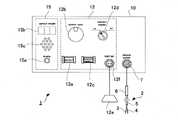
以下、本発明の実施の形態について、添付図面を参照して説明する。図1は、本発明の一実施形態に係る焼灼装置の概略構成図である。図1に示すように、焼灼装置1は、施術者が把持して操作するハンドピース2と、電源装置10とを備えている。 BEST MODE FOR CARRYING OUT THE INVENTION Hereinafter, embodiments of the present invention will be described with reference to the accompanying drawings. FIG. 1 is a schematic configuration diagram of a cautery device according to one embodiment of the present invention. As shown in FIG. 1 , the
ハンドピース2は、細長棒状の一対の電極3,4を備えている。電極3,4は可撓性のシース5により被覆されており、シース5の基端側に把持部6を備えている。電極3,4の先端部は、生体組織100に接触可能となるようにシース5から露出しており、生体組織100に接触した状態で、電極3,4間に高周波電流を印加することにより、接触部近傍の生体組織100を焼灼することができる。一対の電極3,4は、生体組織100との接触面が、球面などの湾曲面により形成されてもよい。 The
図2は、図1に示す焼灼装置の要部正面図である。図1および図2に示すように、電源装置10は、筐体状に構成されており、電源部11、操作部12、制御部13、検出部14および出力部15を備えている。一対の電極3,4は、電源装置10の筐体表面に設けられた接続部7に、配線を介して着脱可能に接続される。 FIG. 2 is a front view of a main portion of the cautery device shown in FIG. 1; As shown in FIGS. 1 and 2 , the
電源部11は、一対の電極3,4に供給する高周波電力を発生する。電源部11は、外部の商用電源等を使用してもよい。 The
操作部12は、図2に示すように、動作モードを入力可能な2つのボタン12a,12cを備えている。「output」と表示された一方のボタン12aは、焼灼モードを選択するための焼灼モード選択スイッチである。焼灼モードは、一対の電極3,4により生体組織100を焼灼するモードであり、電極3,4に印加される焼灼電力の大きさは、調整ダイヤル12bの操作により調整することができる。また、「contact output」と表示された他方のボタン12cは、探索モードを選択するための探索モード選択スイッチである。探索モードは、一対の電極3,4が生体組織に到達したか否かを探索するモードであり、電極3,4に、生体組織100を焼灼しない探索電力が印加される。 The
操作部12は、アラーム切替スイッチ12dおよびフットスイッチ12eを更に備えている。アラーム切替スイッチ12dは、出力部15からの音による通知のオンオフを切り替えるためのスイッチである。また、フットスイッチ12eは、施術者が足による操作で焼灼モードを選択可能なスイッチであり、配線を介して、電源装置10の筐体表面に設けられた接続部12fに着脱可能に接続されている。 The
制御部13は、CPU等からなり、操作部12の操作により入力された動作モードに基づき、電源部11から電極3,4に供給する電力を制御する。また、制御部13は、出力部15の出力制御を行う。 The
検出部14は、電源部11から電極3,4に高周波電力を供給したときの通電電流を検出する。電極3,4の通電電流は、電極3,4間のインピーダンスに応じて変化するため、検出部14は、電流値として出力する構成以外に、インピーダンスとして出力する構成であってもよい。 The
出力部15は、図2に示すように、焼灼装置1のオンオフ状態を示す電源ランプ15aと、電極3,4の通電状態を示す出力ランプ15bと、上記のアラーム切替スイッチ12dがオンの状態で音を出力するスピーカ15cとを備えており、電極3,4の通電状態を出力する。電源ランプ15aおよび出力ランプ15bは、例えばLEDからなる。 As shown in FIG. 2, the
次に、上記の構成を備える焼灼装置1の作動を説明する。例えば、脳外科手術等において生体組織の出血箇所を焼灼する場合、施術者は、探索モード選択スイッチ12cを押圧して探索モードを選択した後、ハンドピース2を操作して、電極3,4の先端を所望の生体組織に向けて移動させる。 Next, the operation of the
探索モードにおいては、制御部13は、電源部11から電極3,4に高周波電力である探索電力を供給する。印加される探索電力の大きさは、生体組織を焼灼しない程度の微弱電力であり、例えば約0.5Wである。探索モードにおいて、電極3,4の先端部が所望の生体組織に到達すると、電極3,4間のインピーダンスが変化することにより、検出部14が検出する電流値が変化する(例えば、0.04Arms)。所望の生体組織のインピーダンスは予め把握することができるため、制御部13は、検出部14の検出に基づいて、電極3,4が所望の生体組織に到達したか否かを判別することができる。 In the search mode, the
制御部13は、電極3,4の通電状態に基づく上記の判別結果を出力部15から出力する。すなわち、電極3,4が所望の生体組織に到達するまでは、出力ランプ15bから出力される点滅光の点滅周期、および、スピーカ15cから出力される断続音の断続周期を、到達前であることを示す周期(例えば、毎分48回程度)となるように制御する。一方、電極3,4が所望の生体組織に到達すると、上記の点滅光の点滅周期および断続音の断続周期を変化させて、到達後であることを示す周期(例えば、毎分120回程度)となるように制御する。出力部15の出力変化は、特に限定されるものではなく、例えば、生体組織への到達前後で音の大きさや光の輝度が変化する構成であってもよい。出力部15は、電源装置10の筐体に設ける代わりに、焼灼ヒータ1に設けてもよい。 The
探索モードにおいて、このような出力部15の制御が行われることにより、施術者は、電極3,4が所望の生体組織に到達したか否かを、視覚または聴覚により容易且つ正確に判別することができる。施術者は、断続音による判別が不要な場合には、アラーム切替スイッチ12dをオフにすることで、出力部15から点滅光のみを出力させることができる。なお、出力部15は、出力ランプ15bを備えずに、音のみが出力される構成にすることもできる。 By controlling the
施術者は、電極3,4が所望の生体組織に到達したことを出力部15の出力により確認した後、焼灼モード選択スイッチ12aまたはフットスイッチ12eの操作により焼灼モードを選択し、調整ダイヤル12bの操作により、所望の生体組織の焼灼に適した焼灼電力を電極3,4に印加する。このように、探索モードで所望の生体組織への到達を確認した後、焼灼モードで生体組織の焼灼を迅速に開始して、出血箇所の止血等を行うことができる。 After confirming that the
本実施形態の焼灼装置1は、一対の電極3,4を備えるバイポーラ式の構成としているが、単一の電極と対極板との間で通電を行うモノポーラ式の構成であってもよい。また、高周波通電による焼灼以外に、マイクロ波などを利用した焼灼にも本発明を適用することができる。 The
1 焼灼装置
3,4 電極
10 電源装置
11 電源部
12 操作部
13 制御部
14 検出部
15 出力部
100 生体組織1
Claims (3)
Translated fromJapanese前記電源装置は、動作モードを入力可能な操作部と、入力された動作モードに基づき前記電極に供給する電力を制御する制御部と、前記電極の通電電流を検出する検出部と、前記電極の通電状態を出力する出力部とを備え、
前記制御部は、前記操作部から焼灼モードが入力されると、前記電極に対して生体組織を焼灼可能な焼灼電力を供給する一方、前記操作部から探索モードが入力されると、前記電極に対して生体組織を焼灼しない探索電力を供給し、前記検出部が検出した通電電流の変化に基づき前記出力部の出力を制御する焼灼装置。An ablation device that includes an electrode whose tip portion contacts a living tissue and a power supply device that is connected to the electrode, and that cauterizes the living tissue by supplying power from the power supply device to the electrode,
The power supply device includes an operation unit that can input an operation mode, a control unit that controls power supplied to the electrode based on the input operation mode, a detection unit that detects the current flowing through the electrode, and and an output unit that outputs an energized state,
When a cauterization mode is input from the operation unit, the control unit supplies cauterization power capable of cauterizing living tissue to the electrodes. A cauterization device that supplies search power that does not cauterize living tissue, and controls the output of the output section based on changes in the energized current detected by the detection section.
前記制御部は、断続音の断続周期または点滅光の点滅周期の少なくとも一方を変化させることにより、前記判別結果を出力する請求項2に記載の焼灼装置。The output unit outputs at least one of intermittent sound and flashing light,
The cauterization apparatus according to claim 2, wherein the control unit outputs the determination result by changing at least one of an intermittent period of the intermittent sound and a blinking period of the blinking light.
Priority Applications (1)
| Application Number | Priority Date | Filing Date | Title |
|---|---|---|---|
| JP2021055255AJP2022152469A (en) | 2021-03-29 | 2021-03-29 | Cauterization device |
Applications Claiming Priority (1)
| Application Number | Priority Date | Filing Date | Title |
|---|---|---|---|
| JP2021055255AJP2022152469A (en) | 2021-03-29 | 2021-03-29 | Cauterization device |
Publications (1)
| Publication Number | Publication Date |
|---|---|
| JP2022152469Atrue JP2022152469A (en) | 2022-10-12 |
Family
ID=83555690
Family Applications (1)
| Application Number | Title | Priority Date | Filing Date |
|---|---|---|---|
| JP2021055255APendingJP2022152469A (en) | 2021-03-29 | 2021-03-29 | Cauterization device |
Country Status (1)
| Country | Link |
|---|---|
| JP (1) | JP2022152469A (en) |
Citations (6)
| Publication number | Priority date | Publication date | Assignee | Title |
|---|---|---|---|---|
| JPH10146344A (en)* | 1996-11-20 | 1998-06-02 | Olympus Optical Co Ltd | Electric operating device |
| US20080275465A1 (en)* | 2005-12-06 | 2008-11-06 | Saurav Paul | Design of Handle Set for Ablation Catheter with Indicators of Catheter and Tissue Parameters |
| JP2013111332A (en)* | 2011-11-30 | 2013-06-10 | Fukuda Denshi Co Ltd | Cauterization condition notification device |
| JP2014516723A (en)* | 2011-06-01 | 2014-07-17 | ボストン サイエンティフィック サイムド,インコーポレイテッド | Ablation probe with ultrasound imaging capability |
| WO2016153561A1 (en)* | 2015-03-25 | 2016-09-29 | Advanced Cardiac Therapeutics, Inc. | Contact sensing systems and methods |
| WO2016170897A1 (en)* | 2015-04-21 | 2016-10-27 | オリンパス株式会社 | Medical device and operating method for medical device |
- 2021
- 2021-03-29JPJP2021055255Apatent/JP2022152469A/enactivePending
Patent Citations (9)
| Publication number | Priority date | Publication date | Assignee | Title |
|---|---|---|---|---|
| JPH10146344A (en)* | 1996-11-20 | 1998-06-02 | Olympus Optical Co Ltd | Electric operating device |
| US20080275465A1 (en)* | 2005-12-06 | 2008-11-06 | Saurav Paul | Design of Handle Set for Ablation Catheter with Indicators of Catheter and Tissue Parameters |
| JP2009518150A (en)* | 2005-12-06 | 2009-05-07 | セント・ジュード・メディカル・エイトリアル・フィブリレーション・ディヴィジョン・インコーポレーテッド | Method for displaying catheter electrode-tissue contact in an electroanatomical mapping and navigation system |
| JP2009518130A (en)* | 2005-12-06 | 2009-05-07 | セント・ジュード・メディカル・エイトリアル・フィブリレーション・ディヴィジョン・インコーポレーテッド | Evaluation of electrode coupling for tissue ablation |
| JP2014516723A (en)* | 2011-06-01 | 2014-07-17 | ボストン サイエンティフィック サイムド,インコーポレイテッド | Ablation probe with ultrasound imaging capability |
| JP2013111332A (en)* | 2011-11-30 | 2013-06-10 | Fukuda Denshi Co Ltd | Cauterization condition notification device |
| WO2016153561A1 (en)* | 2015-03-25 | 2016-09-29 | Advanced Cardiac Therapeutics, Inc. | Contact sensing systems and methods |
| JP2018510709A (en)* | 2015-03-25 | 2018-04-19 | アドバンスド カーディアク セラピューティクス,インコーポレイテッド | Contact detection system and method |
| WO2016170897A1 (en)* | 2015-04-21 | 2016-10-27 | オリンパス株式会社 | Medical device and operating method for medical device |
Similar Documents
| Publication | Publication Date | Title |
|---|---|---|
| US8945122B2 (en) | Power glove | |
| KR101805115B1 (en) | Fixed position rf electrode | |
| EP2531132B1 (en) | Electrosurgical instrument and system | |
| JP4656755B2 (en) | Electrosurgical equipment | |
| US8128622B2 (en) | Electrosurgical pencil having a single button variable control | |
| JP2003116871A (en) | Surgical tool | |
| JP2012081266A (en) | Electrosurgical cobb elevator instrument | |
| JP2011527612A5 (en) | ||
| JP2011529761A (en) | Electrosurgical instrument and electrosurgical system | |
| JP2006187668A (en) | Operation system | |
| JPH10225462A (en) | Electric operating device | |
| CN103596514B (en) | Electrosurgical system | |
| JPWO2006038646A1 (en) | High frequency treatment device | |
| JP2007509646A (en) | Oxygen detection during surgical procedures | |
| JP2002306507A (en) | Surgical apparatus and method for preventing foreign matter from adhering to surgical apparatus | |
| JP2022152469A (en) | Cauterization device | |
| JP2001170070A (en) | Medical treatment instrument | |
| JPH08308851A (en) | Electrosurgical device | |
| JP2009125344A (en) | Endoscopic high-frequency snare device, endoscopic high-frequency snare device and driving device thereof | |
| WO2003105708A1 (en) | Resectoscope | |
| CN215306445U (en) | Wireless nerve monitoring shear type ultrasonic knife | |
| JP3938707B2 (en) | Electrosurgical equipment | |
| JPH08294494A (en) | Electrical operation device | |
| JP2022152470A (en) | Cauterization heater | |
| WO2003105707A1 (en) | Resectoscope |
Legal Events
| Date | Code | Title | Description |
|---|---|---|---|
| A621 | Written request for application examination | Free format text:JAPANESE INTERMEDIATE CODE: A621 Effective date:20240126 | |
| A131 | Notification of reasons for refusal | Free format text:JAPANESE INTERMEDIATE CODE: A131 Effective date:20240913 | |
| A977 | Report on retrieval | Free format text:JAPANESE INTERMEDIATE CODE: A971007 Effective date:20240913 | |
| A02 | Decision of refusal | Free format text:JAPANESE INTERMEDIATE CODE: A02 Effective date:20250207 |