JP2022150958A - Biomass combustion equipment and combustion ash treatment method - Google Patents
Biomass combustion equipment and combustion ash treatment methodDownload PDFInfo
- Publication number
- JP2022150958A JP2022150958AJP2021053799AJP2021053799AJP2022150958AJP 2022150958 AJP2022150958 AJP 2022150958AJP 2021053799 AJP2021053799 AJP 2021053799AJP 2021053799 AJP2021053799 AJP 2021053799AJP 2022150958 AJP2022150958 AJP 2022150958A
- Authority
- JP
- Japan
- Prior art keywords
- ash
- combustion
- biomass
- exhaust gas
- chemical
- Prior art date
- Legal status (The legal status is an assumption and is not a legal conclusion. Google has not performed a legal analysis and makes no representation as to the accuracy of the status listed.)
- Granted
Links
Images


Classifications
- Y—GENERAL TAGGING OF NEW TECHNOLOGICAL DEVELOPMENTS; GENERAL TAGGING OF CROSS-SECTIONAL TECHNOLOGIES SPANNING OVER SEVERAL SECTIONS OF THE IPC; TECHNICAL SUBJECTS COVERED BY FORMER USPC CROSS-REFERENCE ART COLLECTIONS [XRACs] AND DIGESTS
- Y02—TECHNOLOGIES OR APPLICATIONS FOR MITIGATION OR ADAPTATION AGAINST CLIMATE CHANGE
- Y02W—CLIMATE CHANGE MITIGATION TECHNOLOGIES RELATED TO WASTEWATER TREATMENT OR WASTE MANAGEMENT
- Y02W30/00—Technologies for solid waste management
- Y02W30/20—Waste processing or separation
Landscapes
- Solid-Fuel Combustion (AREA)
- Incineration Of Waste (AREA)
- Gasification And Melting Of Waste (AREA)
Abstract
Translated fromJapaneseDescription
Translated fromJapanese本発明は、バイオマス燃料を燃焼するバイオマス燃焼設備、及び燃焼灰処理方法に関する。 TECHNICAL FIELD The present invention relates to a biomass combustion facility for burning biomass fuel and a method for treating combustion ash.
バイオマス燃料として、例えば、木質バイオマス燃料は、再生可能エネルギー資源の一つとして注目されている。木質バイオマス燃料を発電用燃料として利用することによって、化石燃料を用いる場合よりも二酸化炭素の排出量を削減することができるとともに、山林の保全性を高め、林業の活性化も図ることができる。 As a biomass fuel, for example, woody biomass fuel is attracting attention as one of renewable energy resources. By using woody biomass fuel as a fuel for power generation, it is possible to reduce carbon dioxide emissions compared to using fossil fuels, improve the conservation of forests, and revitalize the forestry industry.
木質バイオマス燃料の燃焼に伴い発生する燃焼灰は、その再利用がなければ循環型社会に組み込めず、廃棄処分するしかない。燃焼灰の再利用に関し、木質バイオマス燃料には、肥料成分としてカリウムが多く含まれていることに着目し、燃焼灰に含まれるカリウムを肥料の原料等として再利用するようにした燃焼装置が提案されている(例えば、特許文献1を参照)。 The combustion ash generated by the combustion of woody biomass fuel cannot be incorporated into a recycling-oriented society without its reuse, and must be disposed of. Concerning the reuse of combustion ash, focusing on the fact that woody biomass fuel contains a large amount of potassium as a fertilizer component, we proposed a combustion device that reuses the potassium contained in combustion ash as a raw material for fertilizer. (See
特許文献1で開示された燃焼装置は、木質バイオマス燃料を燃焼する燃焼炉からの排ガスに含まれる燃焼灰をバグフィルタによって集塵し、集塵した燃焼灰を、分級機を用いて粗粉と微粉とに分級し、カリウム成分濃度が比較的高い微粉を取り出すように構成されている。 The combustion apparatus disclosed in
特許文献1の燃焼装置では、分級した燃焼灰のうち、カリウム成分濃度が比較的高い微粉については肥料の原料等として再利用されるものの、カリウム成分濃度が低い粗粉については再利用されずに廃棄されており、燃焼灰の全体が肥料として十分に有効利用されていない。再利用されずに廃棄される粗粉は、産業廃棄物として処分されるため、処分費が嵩み、それが燃焼灰を肥料として普及させる上での阻害要因となっている。 In the combustion apparatus of
本発明は、上記の課題に鑑みてなされたものであり、バイオマス燃料の燃焼によって生じた燃焼灰の粒径にかかわらず肥料成分を燃焼灰全体に含ませることができ、これによって、燃焼灰を肥料として十分に有効利用することができるバイオマス燃焼設備、及び燃焼灰処理方法を提供することを目的とする。 The present invention has been made in view of the above problems, and the fertilizer component can be included in the entire combustion ash regardless of the particle size of the combustion ash generated by the combustion of biomass fuel. An object of the present invention is to provide a biomass combustion facility and a method for treating combustion ash that can be sufficiently effectively used as fertilizer.
上記課題を解決するための本発明に係るバイオマス燃焼設備の特徴構成は、
バイオマス燃料を燃焼する燃焼炉と、
前記燃焼炉から排出される排ガスに含まれる燃焼灰を回収可能な排ガス処理装置と、
前記燃焼灰に肥料成分を含む薬剤を添加する添加装置と、
を備えることにある。The characteristic configuration of the biomass combustion equipment according to the present invention for solving the above problems is
a combustion furnace for burning biomass fuel;
an exhaust gas treatment device capable of recovering combustion ash contained in exhaust gas discharged from the combustion furnace;
an adding device for adding a chemical containing a fertilizer component to the combustion ash;
It is to prepare
本構成のバイオマス燃焼設備によれば、バイオマス燃料の燃焼によって生じた燃焼灰の粒径にかかわらず肥料成分を燃焼灰全体に含ませることができるので、燃焼灰を肥料として十分に有効利用することができる。 According to the biomass combustion equipment of this configuration, the fertilizer component can be included in the entire combustion ash regardless of the particle size of the combustion ash generated by the combustion of biomass fuel, so the combustion ash can be sufficiently and effectively used as fertilizer. can be done.
本発明に係るバイオマス燃焼設備において、
前記添加装置は、
前記燃焼灰に含まれる肥料成分濃度を測定する灰用測定部と、
前記灰用測定部の測定結果に基づいて前記薬剤の添加量を制御する制御部と、
を含むことが好ましい。In the biomass combustion equipment according to the present invention,
The addition device is
an ash measurement unit that measures the concentration of fertilizer components contained in the combustion ash;
a control unit that controls the amount of the chemical to be added based on the measurement result of the ash measuring unit;
is preferably included.
本構成のバイオマス燃焼設備によれば、薬剤を過不足なく添加することができ、目標とする肥料成分濃度の燃焼灰を得ることができる。従って、燃焼灰を肥料として再利用する上での品質を安定化させることができる。 According to the biomass combustion equipment of this configuration, the chemicals can be added in just the right amount, and combustion ash with the target fertilizer component concentration can be obtained. Therefore, the quality can be stabilized when the combustion ash is reused as fertilizer.
本発明に係るバイオマス燃焼設備において、
前記添加装置は、
前記バイオマス燃料に含まれる肥料成分濃度を測定する燃料用測定部と、
前記燃料用測定部の測定結果に基づいて前記薬剤の添加量を制御する制御部と、
を含むことが好ましい。In the biomass combustion equipment according to the present invention,
The addition device is
a fuel measurement unit that measures the concentration of fertilizer components contained in the biomass fuel;
a control unit that controls the addition amount of the chemical based on the measurement result of the fuel measurement unit;
is preferably included.
本構成のバイオマス燃焼設備によれば、バイオマス燃料に含まれる肥料成分濃度が一定でなくても、肥料成分濃度の変動に追従し、薬剤の添加量を速やかに変更して適正な量の薬剤を添加することができる。従って、燃焼灰を肥料として再利用する上での歩留まりを向上させることができる。 According to the biomass combustion equipment of this configuration, even if the concentration of the fertilizer component contained in the biomass fuel is not constant, it follows the fluctuation of the concentration of the fertilizer component and quickly changes the amount of chemical added to provide an appropriate amount of chemical. can be added. Therefore, it is possible to improve the yield in reusing the combustion ash as fertilizer.
本発明に係るバイオマス燃焼設備において、
前記添加装置は、
前記燃焼灰に含まれる肥料成分濃度を測定する灰用測定部と、
前記バイオマス燃料に含まれる肥料成分濃度を測定する燃料用測定部と、
前記灰用測定部及び前記燃料用測定部の測定結果に基づいて前記薬剤の添加量を制御する制御部と、
を含むことが好ましい。In the biomass combustion equipment according to the present invention,
The addition device is
an ash measurement unit that measures the concentration of fertilizer components contained in the combustion ash;
a fuel measurement unit that measures the concentration of fertilizer components contained in the biomass fuel;
a control unit that controls the addition amount of the chemical based on the measurement results of the ash measuring unit and the fuel measuring unit;
is preferably included.
本構成のバイオマス燃焼設備によれば、バイオマス燃料に含まれる肥料成分濃度が一定でなくても、肥料成分濃度の変動に追従し、薬剤の添加量を速やかに変更して適正な量の薬剤を過不足なく添加することができ、しかも目標とする肥料成分濃度の燃焼灰を確実に得ることができる。従って、燃焼灰を肥料として再利用する上での品質を安定化させることができるとともに、歩留まりを向上させることができる。 According to the biomass combustion equipment of this configuration, even if the concentration of the fertilizer component contained in the biomass fuel is not constant, it follows the fluctuation of the concentration of the fertilizer component and quickly changes the amount of chemical added to provide an appropriate amount of chemical. It can be added in just the right amount, and moreover, combustion ash with a target concentration of fertilizer components can be reliably obtained. Therefore, it is possible to stabilize the quality in reusing the combustion ash as fertilizer and improve the yield.
本発明に係るバイオマス燃焼設備において、
前記排ガス処理装置は、前記排ガスの流路に沿って配される複数の排ガス処理部を含み、
前記灰用測定部は、前記複数の排ガス処理部のうちの少なくとも二基の排ガス処理部から回収される前記燃焼灰が集合した集合灰の肥料成分濃度を測定することが好ましい。In the biomass combustion equipment according to the present invention,
The exhaust gas treatment device includes a plurality of exhaust gas treatment units arranged along the flow path of the exhaust gas,
It is preferable that the ash measurement unit measures the concentration of fertilizer components in aggregated ash in which the combustion ash collected from at least two of the plurality of exhaust gas treatment units are aggregated.
本構成のバイオマス燃焼設備によれば、複数の排ガス処理部のうちの少なくとも二基の排ガス処理部から回収される燃焼灰が集合した集合灰の肥料成分濃度を測定するようにされているので、肥料成分濃度を効率良く正確に測定することができる。 According to the biomass combustion equipment of this configuration, the fertilizer component concentration of aggregated ash collected from at least two exhaust gas processing units out of the plurality of exhaust gas processing units is measured. Fertilizer component concentration can be measured efficiently and accurately.
本発明に係るバイオマス燃焼設備において、
前記添加装置は、前記集合灰に前記薬剤を添加することが好ましい。In the biomass combustion equipment according to the present invention,
Preferably, the adding device adds the chemical agent to the aggregated ash.
本構成のバイオマス燃焼設備によれば、肥料成分を効率良く添加することができる。 According to the biomass combustion equipment of this configuration, fertilizer components can be efficiently added.
本発明に係るバイオマス燃焼設備において、
前記複数の排ガス処理部は、前記排ガスと熱交換する少なくとも一つの熱交換装置と、前記熱交換装置の排ガス流れ下流側に配される集塵装置とを含み、
前記添加装置は、前記熱交換装置と前記集塵装置との間の排ガス流路に前記薬剤を添加することが好ましい。In the biomass combustion equipment according to the present invention,
The plurality of exhaust gas processing units include at least one heat exchange device that exchanges heat with the exhaust gas, and a dust collector arranged downstream of the heat exchange device in the flow of the exhaust gas,
Preferably, the addition device adds the chemical to an exhaust gas flow path between the heat exchange device and the dust collector.
本構成のバイオマス燃焼設備によれば、熱交換装置において熱交換がなされた後の比較的温度が低い排ガスが流通される、熱交換装置と集塵装置との間の排ガス流路に薬剤が添加されることになる。このため、薬剤の肥料成分が排ガスの熱から受ける影響を低く抑えることができる。従って、薬剤の肥料成分が排ガスの熱によって揮散したり溶融したりした後に、排ガス流路の構成面に接触して固化し、付着・堆積することを防ぐことができ、薬剤の肥料成分に起因する排ガス流路の閉塞等の不具合を防止しつつ、排ガス流れを利用して燃焼灰に薬剤を均一に添加することができる。また、肥料成分を含む薬剤自体の高温場での分解を防ぐことができ、燃焼灰を肥料として再利用する上での品質を安定化させることができる。 According to the biomass combustion equipment of this configuration, the chemical is added to the exhaust gas flow path between the heat exchanger and the dust collector, through which the exhaust gas having a relatively low temperature after heat exchange in the heat exchanger is circulated. will be Therefore, the influence of the heat of the exhaust gas on the fertilizer component of the chemical can be kept low. Therefore, after the fertilizer component of the chemical volatilizes or melts due to the heat of the exhaust gas, it can be prevented from solidifying, adhering and depositing in contact with the surface constituting the exhaust gas flow path, and It is possible to uniformly add the chemical to the combustion ash using the exhaust gas flow while preventing problems such as clogging of the exhaust gas flow path. In addition, it is possible to prevent decomposition of the chemicals themselves containing fertilizer components in a high-temperature field, and stabilize the quality when recycling combustion ash as fertilizer.
本発明に係るバイオマス燃焼設備において、
別のバイオマス燃焼設備から発生する燃焼灰を前記薬剤として用いることが好ましい。In the biomass combustion equipment according to the present invention,
It is preferable to use combustion ash generated from another biomass combustion facility as the agent.
本構成のバイオマス燃焼設備によれば、例えば、別のバイオマス燃焼設備から発生する燃焼灰にカリウム等の肥料成分が比較的高濃度で含まれている場合において、別のバイオマス燃焼設備から発生する燃焼灰を薬剤として用いることにより、実際の薬剤の使用量を削減することができ、別のバイオマス燃焼設備を含むバイオマス燃焼設備全体で総合的に経済性を高めることができる。 According to the biomass combustion equipment of this configuration, for example, when combustion ash generated from another biomass combustion equipment contains fertilizer components such as potassium at a relatively high concentration, combustion generated from another biomass combustion equipment By using ash as a chemical, the amount of actual chemical used can be reduced, and the overall economic efficiency of the entire biomass combustion facility including other biomass combustion facilities can be improved.
次に、上記課題を解決するための本発明に係る燃焼灰処理方法の特徴構成は、
バイオマス燃料を燃焼する燃焼炉から排出される排ガスに含まれる燃焼灰を回収する回収工程と、
前記燃焼灰に肥料成分を含む薬剤を添加する添加工程と、
を包含することにある。Next, the characteristic configuration of the combustion ash disposal method according to the present invention for solving the above problems is as follows:
a recovery step of recovering combustion ash contained in exhaust gas discharged from a combustion furnace that burns biomass fuel;
an adding step of adding a chemical containing a fertilizer component to the combustion ash;
to include
本構成の燃焼灰処理方法によれば、バイオマス燃料の燃焼によって生じた燃焼灰の粒径にかかわらず肥料成分を燃焼灰全体に含ませることができるので、燃焼灰を肥料として十分に有効利用することができる。 According to the combustion ash treatment method of this configuration, the fertilizer component can be included in the entire combustion ash regardless of the particle size of the combustion ash generated by the combustion of biomass fuel, so the combustion ash can be sufficiently and effectively used as fertilizer. be able to.
本発明に係る燃焼灰処理方法において、
前記添加工程において、前記燃焼灰に含まれる肥料成分濃度の測定結果に基づいて前記薬剤の添加量を制御する制御工程を含むことが好ましい。In the method for treating combustion ash according to the present invention,
It is preferable that the adding step includes a controlling step of controlling the amount of the chemical to be added based on the measurement result of the concentration of the fertilizer component contained in the combustion ash.
本構成の燃焼灰処理方法によれば、薬剤を過不足なく添加することができ、目標とする肥料成分濃度の燃焼灰を得ることができる。従って、燃焼灰を肥料として再利用する上での品質を安定化させることができる。 According to the combusted ash disposal method of this configuration, the chemicals can be added just enough to obtain combusted ash having a target concentration of fertilizer components. Therefore, the quality can be stabilized when the combustion ash is reused as fertilizer.
本発明に係る燃焼灰処理方法において、
前記添加工程において、前記バイオマス燃料に含まれる肥料成分濃度の測定結果に基づいて前記薬剤の添加量を制御する制御工程を含むことが好ましい。In the method for treating combustion ash according to the present invention,
It is preferable that the addition step includes a control step of controlling the addition amount of the chemical agent based on the measurement result of the concentration of the fertilizer component contained in the biomass fuel.
本構成の燃焼灰処理方法によれば、バイオマス燃料に含まれる肥料成分濃度が一定でなくても、肥料成分濃度の変動に追従し薬剤の添加量を速やかに変更して適正な量の薬剤を添加することができる。従って、燃焼灰を肥料として再利用する上での歩留まりを向上させることができる。 According to the combusted ash treatment method of this configuration, even if the concentration of the fertilizer component contained in the biomass fuel is not constant, the amount of the chemical to be added is quickly changed in accordance with the fluctuation of the concentration of the fertilizer component, and an appropriate amount of the chemical is supplied. can be added. Therefore, it is possible to improve the yield in reusing the combustion ash as fertilizer.
以下、本発明について、図面を参照しながら説明する。本発明のバイオマス燃焼設備において燃焼させるバイオマス燃料とは、化石燃料以外の植物や農産物等の自然界の有機性資源から抽出した生物由来の燃料である。バイオマス燃料としては、例えば、廃棄木材、間伐材、流木、草類、生活廃棄物、汚泥、家畜の糞尿、エネルギー作物(農作物)、これらを原料としたリサイクル燃料(ペレットやチップ)等が挙げられるが、以下の実施形態では、木質バイオマス燃料(廃棄木材、間伐材、木質チップ、木質ペレット等)や、PKS(Palm Kernel Shell)をはじめとした農作物残渣等の生物由来の有機性資源を含む燃料(植物系燃料)を燃焼するバイオマス燃焼設備、及び当該バイオマス燃料を燃焼したときに発生する燃焼灰の有効利用を図る燃焼灰処理方法を例に挙げて説明する。ただし、本発明は、以下に説明する実施形態や図面に記載される構成に限定されることは意図しない。 The present invention will be described below with reference to the drawings. The biomass fuel to be burned in the biomass combustion equipment of the present invention is a biological fuel extracted from natural organic resources such as plants and agricultural products other than fossil fuels. Examples of biomass fuels include waste wood, thinned wood, driftwood, grasses, household waste, sludge, livestock manure, energy crops (crops), and recycled fuels (pellets and chips) made from these raw materials. However, in the following embodiments, woody biomass fuels (waste wood, thinned wood, wood chips, wood pellets, etc.) and agricultural residue such as PKS (Palm Kernel Shell) Fuels containing biologically derived organic resources A biomass combustion facility that burns (plant-based fuel) and a combustion ash treatment method for effectively utilizing combustion ash generated when the biomass fuel is burned will be described as examples. However, the present invention is not intended to be limited to the embodiments described below or the configurations described in the drawings.
〔第一実施形態〕
図1は、本発明の第一実施形態に係るバイオマス燃焼設備の概略構成を示すブロック図である。[First Embodiment]
FIG. 1 is a block diagram showing a schematic configuration of biomass combustion equipment according to the first embodiment of the present invention.
<全体構成>
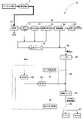
図1に示すバイオマス燃焼設備1Aは、搬送装置5によって搬送されるバイオマス燃料を燃焼する燃焼炉10と、燃焼炉10から排出される排ガスに含まれる燃焼灰を回収可能な排ガス処理装置30と、燃焼灰に肥料成分を含む薬剤を添加する添加装置60Aとを備えている。<Overall composition>
The
<燃焼炉>
燃焼炉10としては、バイオマス燃料を燃焼することができれば炉の形式は限定されるものではないが、例えば、ストーカ式燃焼炉や流動床式燃焼炉等を挙げることができる。<Combustion Furnace>
As the
ストーカ式燃焼炉は、炉内に配置されたストーカを動かし、ストーカ下部より燃焼空気を送り、バイオマス燃料を乾燥・燃焼・後燃焼させる形式の燃焼炉である。ここで、ストーカとしては、例えば、階段式ストーカとトラベリングストーカとがある。階段式ストーカは、可動火格子と固定火格子とが交互に階段状に配列されたものであり、乾燥段を形成する乾燥ストーカ、燃焼段を形成する燃焼ストーカ、及び後燃焼段を形成する後燃焼ストーカが、バイオマス燃料送り方向の上流側から下流側に向けて順に区分けされている。一方、トラベリングストーカは、炉内においてバイオマス燃料を移動させる方向に所定間隔を存して配される駆動輪及び従動輪に、複数の火格子を互いに回動自在に環状に連結してなる環状火格子体を巻き掛け装着して構成されている。トラベリングストーカにおいては、環状火格子体が周回運動するように駆動され、環状火格子体で受け止めた燃料投入機からのバイオマス燃料を移動させながら環状火格子体上で燃焼させるように構成されている。流動床式燃焼炉は、けい砂等の粒子層の下部から加圧された空気を分散供給して、蓄熱したけい砂等を流動させながら、その中でバイオマス燃料を燃焼させる形式の燃焼炉である。 A stoker-type combustion furnace is a combustion furnace in which a stoker arranged in the furnace is moved, combustion air is sent from the bottom of the stoker, and biomass fuel is dried, burned, and post-burned. Here, the stoker includes, for example, a stepped stoker and a traveling stoker. A stepped stoker is a structure in which movable grates and fixed grates are alternately arranged in a stepped manner, and includes a drying stoker forming a drying stage, a combustion stoker forming a combustion stage, and a post combustion stage forming a post-combustion stage. Combustion stokers are divided in order from the upstream side toward the downstream side in the biomass fuel feeding direction. On the other hand, a traveling stoker is an annular fire in which a plurality of fire grates are rotatably and annularly connected to a driving wheel and a driven wheel which are arranged at a predetermined interval in the direction in which the biomass fuel is moved in the furnace. It is constructed by winding a grid body around it. In the traveling stoker, the ring-shaped grate body is driven to revolve, and the biomass fuel received by the ring-shaped grate body from the fuel injector is moved and burned on the ring-shaped grate body. . A fluidized bed combustion furnace is a combustion furnace that burns biomass fuel while dispersing and supplying pressurized air from the lower part of a particle layer of silica sand, etc., to fluidize the silica sand, etc. that has accumulated heat. be.
<排ガス処理装置>
排ガス処理装置30は、燃焼炉10から排出される排ガスの流路に沿って配される複数の排ガス処理部として、例えば、蒸気発生器31、節炭器32、空気予熱器33、集塵装置34、及び排気塔35を備えている。蒸気発生器31、節炭器32、空気予熱器33、集塵装置34、及び排気塔35は、相互間がダクトによって接続されている。排ガス処理装置30においては、燃焼炉10での燃焼に伴い発生した排ガスが、集塵装置34と排気塔35との間に配設される図示されない誘引送風機の誘引作用により、蒸気発生器31、節炭器32、空気予熱器33、及び集塵装置34にそれぞれこの記載順に送り込まれ、集塵装置34で除塵処理された後の排ガスが排気塔35を通して大気中に放出されるように構成されている。<Exhaust gas treatment device>
The exhaust
<蒸気発生器>
蒸気発生器31は、燃焼炉10の排ガス流れ下流側に配設される熱交換装置である。蒸気発生器31は、燃焼炉10から排出される排ガスが導入されるケーシング内に、熱交換用の多数の伝熱管が配設されてなるものであり、排ガスと伝熱管内を流通する水との間での熱交換により、蒸気を発生させるように構成されている。なお、発生させた蒸気を利用して発電機を駆動するように構成してもよい。<Steam generator>
The
<節炭器>
節炭器32は、蒸気発生器31の排ガス流れ下流側に配設される熱交換装置である。節炭器32は、蒸気発生器31から排出される排ガスが導入されるケーシング内に、熱交換用の多数の伝熱管が配設されてなるものであり、伝熱管内を流通する蒸気発生器31への供給水と排ガスとの間での熱交換により、蒸気発生器31への供給水を加熱するように構成されている。<Coal saver>
The
<空気予熱器>
空気予熱器33は、節炭器32の排ガス流れ下流側に配設される熱交換装置である。空気予熱器33は、節炭器32から排出される排ガスが導入されるケーシング内に、熱交換用の多数の伝熱管が配設されてなるものであり、伝熱管内を流通する図示されないごみピットからの空気と排ガスとの間での熱交換により、ごみピットからの空気を加熱し、加熱したごみピットからの空気を燃焼炉10の一次燃焼用空気として供給するように構成されている。<Air preheater>
The
<集塵装置>
集塵装置34は、図示による詳細説明は省略するが、ケーシングに所要のろ布が組み込まれるとともに、払落し装置が装備されて構成されている。ケーシングの内部は、ケージプレートによって上下に仕切られており、ケーシングの内部には、ケージプレートの下側にろ過処理前排ガス室が、ケージプレートの上側にろ過処理後排ガス室が、それぞれ区画形成されている。ろ過処理前排ガス室は、ダクトを介して空気予熱器33に接続されている。ろ過処理後排ガス室は、ダクトを介して図示されない誘引送風機に接続されている。ケージプレートには、ろ布の吊り下げ用の開口部が所要個数設けられており、各開口部からは、ろ布がろ過処理前排ガス室内に配されるように吊り下げ支持されている。ろ布は、円筒状の袋体であり、閉鎖された一端側(下端側)がろ過処理前排ガス室内に差し込まれる一方で、開放された他端側(上端側)がろ過処理後排ガス室に臨ませて配され、該ろ布の内部には、その円筒形状を維持するための骨材が組み込まれている。払落し装置は、集塵装置34における排ガス流路の上流側と下流側との差圧が所定値以上となったときや、当該差圧の値に関わらず一定期間毎に、エアコンプレッサからの圧縮空気を、配管類を介して所要の噴射ノズルから払落し対象(逆洗対象)のろ布の内表面側へと噴射することにより、ろ布の外表面側に付着堆積した燃焼灰等を吹き飛ばすことができるように構成されている。<Dust collector>
The
<排気塔>
排気塔35は、燃焼の過程で排出される排ガスが持つ上昇気流を風による外乱から保護し、燃焼を促進させる筒状の構造物(煙突)である。<exhaust tower>
The
蒸気発生器31、節炭器32及び空気予熱器33の各熱交換装置において、伝熱管の表面には、排ガスに含まれる燃焼灰が付着・堆積する。このため、各熱交換装置においては、例えば、蒸気や圧縮空気、圧力波等を利用して伝熱管の表面に付着した燃焼灰を吹き飛ばして除去するようにされている。除去された燃焼灰は、各熱交換装置におけるケーシングの下部に形成されたホッパ部を通して外部に排出される。排出された燃焼灰は、振動スクリーン41によって異物が除去された後、灰搬送ライン42を介して燃焼灰の一時貯留装置であるバンカー43に送り込まれる。 In each heat exchange device of the
集塵装置34において、払落し装置によりろ布の外表面から除去された燃焼灰は、集塵装置34のケーシングの下部に形成されたホッパ部を通して外部に排出される。排出された燃焼灰は、振動スクリーン41から送り出される燃焼灰と合流して灰搬送ライン42を介してバンカー43に送り込まれる。 In the
バンカー43には、蒸気発生器31、節炭器32、空気予熱器33、及び集塵装置34の各排ガス処理部から回収された燃焼灰が集められる。バンカー43に集められた燃焼灰(以下、「集合灰」と称する。)は、灰搬送ライン44を介して混練フィーダ45へと送られる。灰搬送ライン44には、添加装置60Aから肥料成分を含む薬剤が添加される。混練フィーダ45には、バンカー43からの集合灰と添加装置60Aからの薬剤とが送り込まれる。混練フィーダ45は、集合灰と薬剤とが均一に混ざった状態となるようにそれらを混練する。これにより、肥料成分濃度が調整された肥料成分濃度調整灰が得られる。肥料成分濃度調整灰は、混練フィーダ45から灰搬送ライン46を介して複数のサイロ47,48に肥料成分の濃度に応じて振り分けられて貯蔵される。 In the
次に、肥料成分を含む薬剤を添加する添加装置60Aについて詳述する。添加装置60Aは、灰搬送ライン44上の集合灰に含まれる肥料成分濃度を測定する第一灰用測定部61と、灰搬送ライン46上の肥料成分濃度調整灰に含まれる肥料成分濃度を測定する第二灰用測定部62と、灰搬送ライン44上の集合灰に肥料成分を含む薬剤を添加する添加部63と、灰用測定部61,62の測定結果に基づいて集合灰に対し添加すべき薬剤の添加量を算出し、算出した添加量となるように添加部63を制御する制御部65とを備えている。 Next, the adding
ここで、薬剤に含まれる肥料成分としては、例えば、カリウム、窒素、リン、カルシウム、マグネシウム、硫黄等が挙げられる。そして、カリウムを含有する化合物、窒素を含有する化合物、リンを含有する化合物、カルシウムを含有する化合物、マグネシウムを含有する化合物、硫黄を含有する化合物等を含む薬剤が添加部63によって灰搬送ライン44上の集合灰に添加される。なお、添加される薬剤に含まれる肥料成分は、単独の肥料成分を含むものであってもよいし、複数種類の肥料成分を含むものであってもよい。 Here, examples of fertilizer components contained in the chemical include potassium, nitrogen, phosphorus, calcium, magnesium, sulfur and the like. Chemicals containing potassium-containing compounds, nitrogen-containing compounds, phosphorus-containing compounds, calcium-containing compounds, magnesium-containing compounds, sulfur-containing compounds, etc. Added to the upper aggregated ash. In addition, the fertilizer component contained in the chemical|medical agent to add may contain a single fertilizer component, and may contain a multiple types of fertilizer component.
<灰用測定部>
灰用測定部61,62としては、例えば、灰搬送ライン44,46上で測定対象(集合灰、肥料成分濃度調整灰)に対し直接的にX線を照射し、測定対象中の元素から放射される特有のエネルギーを有する蛍光X線に基づいて肥料成分の濃度を測定する蛍光X線分析装置が挙げられる。ここで、第一灰用測定部61は、複数の排ガス処理部、すなわち蒸気発生器31、節炭器32、空気予熱器33、及び集塵装置34から回収された集合灰の肥料成分濃度を測定するように構成されている。これにより、肥料成分濃度を効率よく正確に測定することができる。<Measuring unit for ash>
The
なお、測定対象(集合灰、肥料成分濃度調整灰)の肥料成分濃度を測定する手段としては、上記のような、蛍光X線分析装置を用いて直接的にオンライン測定するものに限定されず、例えば、図示されないサンプリング装置によって灰搬送ライン44,46上の測定対象(集合灰、肥料成分濃度調整灰)の一部を取り出し、それを加圧して平坦な表面を有する肥料成分濃度測定用の試料を作成し、その試料を蛍光X線分析装置によって肥料成分濃度を求めるサンプリング測定法によるものが挙げられる。 In addition, the means for measuring the fertilizer component concentration of the measurement target (aggregate ash, fertilizer component concentration adjustment ash) is not limited to direct online measurement using a fluorescent X-ray analyzer as described above, For example, a part of the object to be measured (collected ash, fertilizer component concentration adjustment ash) on the
<添加部>
添加部63としては、例えば、肥料成分を含む薬剤を貯留する薬剤タンクと、薬剤タンクに付設されるフィーダとを備え、薬剤タンクに貯留されている薬剤をフィーダで送り出し、送り出した薬剤を灰搬送ライン44上に供給することができるように構成されるものが挙げられる。なお、複数種類の肥料成分を含む薬剤を灰搬送ライン44上の集合灰に添加する場合、複数種類の肥料成分を混合した薬剤を一つの添加部63を用いて灰搬送ライン44上に供給する態様と、複数種類の肥料成分の種類毎に添加部63を設け、複数の添加部63を用いて灰搬送ライン44上に供給する態様とがある。<Addition part>
The adding
<制御部>
制御部65は、添加部63を含む装置全体を制御可能なコンピュータを主体に構成されるものであり、添加部63におけるフィーダの薬剤送り出し量を制御することにより、薬剤の添加量を制御する。<Control unit>
The
次に、上記のように構成されるバイオマス燃焼設備1Aを用いた燃焼灰処理方法について説明する。 Next, a combustion ash treatment method using the
<回収工程>
バイオマス燃焼設備1Aにおいては、蒸気発生器31、節炭器32及び空気予熱器33の各熱交換装置から排出・合流された燃焼灰を、振動スクリーン41によって異物を除去した後、灰搬送ライン42を介してバンカー43に送り込んで回収する。また、バイオマス燃焼設備1Aにおいては、集塵装置34から排出された燃焼灰を、振動スクリーン41から送り出される燃焼灰と合流させて灰搬送ライン42を介してバンカー43に送り込んで回収する。<Recovery process>
In the
<添加工程>
バンカー43に集められた集合灰を、灰搬送ライン44を介して混練フィーダ45へと送る途中において、添加装置60Aから肥料成分を含む薬剤を集合灰に添加する。こうして、集合灰に薬剤を添加することにより、肥料成分を効率よく添加することができる。<Addition process>
While the collective ash collected in the
<制御工程>
添加工程において、第一灰用測定部61、及び第二灰用測定部62によって測定される、又は上述のサンプリング測定法によって測定される、集合灰に含まれる肥料成分濃度に基づいて、薬剤の添加量を制御する。すなわち、制御部65は、目標とする肥料成分濃度と第一灰用測定部61の測定結果(サンプリング測定法による測定結果)との差分に応じたフィードフォワード制御により添加すべき薬剤の添加量となるように添加部63におけるフィーダの薬剤送り出し量を制御するとともに、目標とする肥料成分濃度と第二灰用測定部62の測定結果(サンプリング測定法による測定結果)との差分に応じたフィードバック制御により添加すべき薬剤の添加量となるように添加部63におけるフィーダの薬剤送り出し量を制御する。これにより、目標とする肥料成分濃度で肥料成分が含有された肥料成分濃度調整灰を確実に得ることができる。<Control process>
In the addition step, based on the fertilizer component concentration contained in the collective ash measured by the first
第一実施形態によれば、バイオマス燃料を燃焼する燃焼炉10から排出される排ガスに含まれる燃焼灰を回収する回収工程と、燃焼灰に肥料成分を含む薬剤を添加する添加工程とを行うことにより、バイオマス燃料の燃焼によって生じた燃焼灰の粒径にかかわらず肥料成分を集合灰全体に含ませることができるので、燃焼灰を肥料として十分に有効利用することができる。また、添加工程において、集合灰に含まれる肥料成分濃度の測定結果に基づいて薬剤の添加量を制御する制御工程を行うことにより、薬剤を過不足なく添加することができ、目標とする肥料成分濃度の肥料成分濃度調整灰を確実に得ることができる。従って、燃焼灰を肥料として再利用する上での品質を安定化させることができる。 According to the first embodiment, the recovery step of recovering the combustion ash contained in the exhaust gas discharged from the
〔第二実施形態〕
図2は、本発明の第二実施形態に係るバイオマス燃焼設備の概略構成を示すブロック図である。本実施形態において、先の実施形態と同一又は同様のものについては図に同一符号を付すに留めてその詳細な説明を省略することとし、以下においては本実施形態に特有の部分を中心に説明することとする(後述する第三実施形態~第六実施形態においても同様)。[Second embodiment]
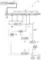
FIG. 2 is a block diagram showing a schematic configuration of biomass combustion equipment according to the second embodiment of the present invention. In this embodiment, the same or similar parts as those in the previous embodiment are denoted by the same reference numerals in the drawings, and the detailed description thereof will be omitted. (The same applies to third to sixth embodiments described later).
図2に示すバイオマス燃焼設備1Bにおいては、第一実施形態のバイオマス燃焼設備1Aにおいて設けられていた第一灰用測定部61、及び第二灰用測定部62が省略され、それらに代えて、バイオマス燃料に含まれる肥料成分濃度を測定する燃料用測定部68を備えている。バイオマス燃焼設備1Bにおいて、添加装置60Bは、主として、添加部63、制御部65及び燃料用測定部68により構成されている。添加装置60Bにおいて、制御部65は、燃料用測定部68の測定結果に基づいて集合灰に対し添加すべき薬剤の添加量を算出し、算出した添加量となるように添加部63を制御する。 In the
<燃料用測定部>
燃料用測定部68としては、例えば、燃料貯蔵塔に貯蔵されているバイオマス燃料に対し直接的にX線を照射し、バイオマス燃料中の元素から放射される特有のエネルギーを有する蛍光X線に基づいて肥料成分の濃度を測定する蛍光X線分析装置が挙げられる。なお、バイオマス燃料の肥料成分濃度を測定する手段としては、蛍光X線分析装置を用いて直接的に測定するものに限定されず、例えば、図示されないサンプリング装置によって燃料貯蔵塔に貯蔵されているバイオマス燃料の一部を取り出し、それを加圧して平坦な表面を有する肥料成分濃度測定用の試料を作成し、その試料を蛍光X線分析装置によって肥料成分濃度を求めるサンプリング測定法によるものが挙げられる。<Measurement part for fuel>
As the
次に、上記のように構成されるバイオマス燃焼設備1Bを用いた燃焼灰処理方法について説明する。回収工程、及び添加工程については、第一実施形態のバイオマス燃焼設備1Aを用いた燃焼灰処理方法と同様であるため、これらの工程についての説明を省略する。第二実施形態で行われる制御工程については、以下の通りである。 Next, a combustion ash treatment method using the
<制御工程>
添加工程において、燃料用測定部68によって測定される、又は上述のサンプリング測定法によって測定される、バイオマス燃料に含まれる肥料成分濃度に基づいて、薬剤の添加量を制御する。すなわち、制御部65は、目標とする肥料成分濃度と燃料用測定部68の測定結果(サンプリング測定法による測定結果)との差分に応じたフィードフォワード制御により添加すべき薬剤の添加量となるように添加部63におけるフィーダの薬剤送り出し量を制御する。これにより、目標とする肥料成分濃度で肥料成分が含有された肥料成分濃度調整灰を得ることができる。<Control process>
In the addition step, the amount of chemical added is controlled based on the concentration of the fertilizer component contained in the biomass fuel measured by the
第二実施形態によれば、燃料用測定部68の測定結果に基づいて薬剤の添加量を制御するように構成されている。このような構成により、バイオマス燃料に含まれる肥料成分濃度が一定でなくても、肥料成分濃度の変動に追従し、薬剤の添加量を速やかに変更して適正な量の薬剤を添加することができる。従って、燃焼灰を肥料として再利用する上での歩留まりを向上させることができる。 According to the second embodiment, the addition amount of the chemical is controlled based on the measurement result of the
〔第三実施形態〕
図3は、本発明の第三実施形態に係るバイオマス燃焼設備の概略構成を示すブロック図である。[Third embodiment]
FIG. 3 is a block diagram showing a schematic configuration of biomass combustion equipment according to a third embodiment of the present invention.
図3に示すバイオマス燃焼設備1Cにおいて、蒸気発生器31、節炭器32及び空気予熱器33の各熱交換装置のケーシングの下部に形成されたホッパ部を通して外部に排出された燃焼灰は、振動スクリーン41によって異物が除去された後、灰搬送ライン51を介して混練フィーダ45に送り込まれる。 In the
第一実施形態のバイオマス燃焼設備1A(図1参照)では、バンカー43に集められた集合灰を、灰搬送ライン44を介して混練フィーダ45へと送る途中において、肥料成分を含む薬剤を集合灰に添加するようにされているのに対し、図3に示す第三実施形態のバイオマス燃焼設備1Cでは、空気予熱器33と、空気予熱器33の排ガス流れ下流側に配される集塵装置34との間の排ガス流路に肥料成分を含む薬剤を添加部63により添加するように構成されている。添加された薬剤は、集塵装置34のケーシング内に導入され、払落し装置によりろ布の外表面から除去された燃焼灰と共に、集塵装置34のケーシングの下部に形成されたホッパ部を通して外部に排出される。集塵装置34から排出された薬剤含有燃焼灰と、振動スクリーン41から送り出される燃焼灰とは、合流して、薬剤と燃焼灰とを含有する集合灰となる。当該集合灰は、灰搬送ライン51を介して混練フィーダ45に送り込まれる。混練フィーダ45は、薬剤と燃焼灰とが均一に混ざった状態となるように集合灰を混練する。これにより、肥料成分濃度が調整された肥料成分濃度調整灰が得られる。 In the
混練フィーダ45からは、肥料成分濃度調整灰が送り出される。混練フィーダ45から送り出される肥料成分濃度調整灰は、灰搬送ライン53を介して複数のサイロ47,48に肥料成分の濃度に応じて振り分けられて貯蔵される。 From the kneading
バイオマス燃焼設備1Cにおいて、添加装置60Cは、主として、第一灰用測定部61、第二灰用測定部62、添加部63、及び制御部65を備えている。第一灰用測定部61は、燃焼灰に含まれる肥料成分濃度を測定する。ここで、第一灰用測定部61の測定対象の燃焼灰は、複数の排ガス処理部(本例では、蒸気発生器31、節炭器32、空気予熱器33、集塵装置34、及び排気塔35の五基)のうちの少なくとも二基の排ガス処理部(本例では、蒸気発生器31、節炭器32、及び空気予熱器33の各熱交換装置)から排出・合流されて振動スクリーン41に導入され、振動スクリーン41によって異物が除去された後、振動スクリーン41から送り出される、灰搬送ライン51上の燃焼灰であって、且つ集塵装置34からの薬剤含有燃焼灰と合流する前の燃焼灰である(以下、この燃焼灰を「振動スクリーン送出燃焼灰」と称する。)。第二灰用測定部62は、灰搬送ライン53上の肥料成分濃度調整灰に含まれる肥料成分濃度を測定する。添加部63は、空気予熱器33と集塵装置34との間の排ガス流路に肥料成分を含む薬剤を添加する。制御部65は、灰用測定部61,62の測定結果に基づいて空気予熱器33と集塵装置34との間の排ガス流路に対し添加すべき薬剤の添加量を算出し、算出した添加量となるように添加部63を制御する。なお、第三実施形態のバイオマス燃焼設備1Cにおいて用いられる添加部63としては、例えば、次のような構成のものが挙げられる(後述する第四実施形態、及び第六実施形態においても同様)。すなわち、添加部63は、集塵装置34の入口側ダクトに接続される薬剤輸送管内にその入口側ダクトに向かう押込み気流を発生させる圧送ブロワと、肥料成分を含む薬剤を貯留する薬剤タンクと、薬剤タンクに貯留されている薬剤を薬剤輸送管内へと供給可能に薬剤タンクと薬剤輸送管との間に介設されるフィーダとを備え、圧送ブロワの作動によって押込み気流を薬剤輸送管内に発生させながら薬剤タンク内に貯留されている薬剤をフィーダによって薬剤輸送管内へと供給することにより、薬剤輸送管内の押込み気流によって薬剤を集塵装置34の入口側ダクトに吹き込むように構成される。 In the
灰用測定部61,62としては、例えば、灰搬送ライン51,53上で測定対象(振動スクリーン送出燃焼灰、肥料成分濃度調整灰)に対し直接的にX線を照射し、測定対象中の元素から放射される特有のエネルギーを有する蛍光X線に基づいて肥料成分の濃度を測定する蛍光X線分析装置が挙げられる。また、蛍光X線分析装置を用いて直接的にオンライン測定する以外に、例えば、図示されないサンプリング装置によって灰搬送ライン51,53上の測定対象(振動スクリーン送出燃焼灰、肥料成分濃度調整灰)の一部を取り出し、それを加圧して平坦な表面を有する肥料成分濃度測定用の試料を作成し、その試料を蛍光X線分析装置によって肥料成分濃度を求めるサンプリング測定法によるものが挙げられる。 The
次に、上記のように構成されるバイオマス燃焼設備1Cを用いた燃焼灰処理方法について説明する。 Next, a combustion ash treatment method using the
<回収工程>
バイオマス燃焼設備1Cにおいては、蒸気発生器31、節炭器32及び空気予熱器33の各熱交換装置から排出・合流された燃焼灰を、振動スクリーン41によって異物を除去した後、灰搬送ライン51を介して混練フィーダ45に送り込んで回収する。また、バイオマス燃焼設備1Cにおいては、集塵装置34から排出された薬剤含有燃焼灰を、振動スクリーン41から送り出される振動スクリーン送出燃焼灰と合流させて灰搬送ライン51を介して混練フィーダ45に送り込んで回収する。<Recovery process>
In the
<添加工程>
添加装置60Cは、空気予熱器33と集塵装置34との間の排ガス流路に肥料成分を含む薬剤を添加する。<Addition process>
The addition device 60</b>C adds a chemical containing a fertilizer component to the exhaust gas flow path between the
<制御工程>
添加工程においては、第一灰用測定部61、及び第二灰用測定部62によって測定される、又は上述のサンプリング測定法によって測定される、振動スクリーン送出燃焼灰、及び肥料成分濃度調整灰に含まれる肥料成分濃度に基づいて、薬剤の添加量を制御する。すなわち、制御部65は、目標とする肥料成分濃度と第一灰用測定部61の測定結果(サンプリング測定法による測定結果)との差分に応じたフィードフォワード制御により添加すべき薬剤の添加量となるように添加部63におけるフィーダの薬剤送り出し量、及び/又は圧送ブロワの薬剤圧送量を制御するとともに、目標とする肥料成分濃度と第二灰用測定部62の測定結果(サンプリング測定法による測定結果)との差分に応じたフィードバック制御により添加すべき薬剤の添加量となるように添加部63におけるフィーダの薬剤送り出し量、及び/又は圧送ブロワの薬剤圧送量を制御する。これにより、目標とする肥料成分濃度で肥料成分が含有された肥料成分濃度調整灰を確実に得ることができる。<Control process>
In the addition step, the vibration screen sent combustion ash and the fertilizer component concentration adjustment ash measured by the first
第三実施形態によれば、蒸気発生器31、節炭器32及び空気予熱器33の各熱交換装置での熱交換がなされた後の比較的温度が低い排ガスが流通される、空気予熱器33と集塵装置34との間の排ガス流路に薬剤が添加されるので、薬剤の肥料成分が排ガスの熱から受ける影響を低く抑えることができる。従って、薬剤の肥料成分が排ガスの熱によって揮散したり溶融したりした後に、排ガス流路の構成面に接触して固化し、付着・堆積することを防ぐことができ、薬剤の肥料成分に起因する排ガス流路の閉塞等の不具合を防止しつつ、排ガス流れを利用して燃焼灰に薬剤を均一に添加することができる。また、肥料成分を含む薬剤自体の高温場での分解を防ぐことができ、燃焼灰を肥料として再利用する上での品質を安定化させることができる。 According to the third embodiment, the air preheater through which the exhaust gas having a relatively low temperature after heat exchange in each heat exchange device of the
〔第四実施形態〕
図4は、本発明の第四実施形態に係るバイオマス燃焼設備の概略構成を示すブロック図である。図4に示すバイオマス燃焼設備1Dにおいては、第三実施形態において設けられていた第一灰用測定部61、及び第二灰用測定部62が省略され、それらに代えて、バイオマス燃料に含まれる肥料成分濃度を測定する燃料用測定部68を備えている。バイオマス燃焼設備1Dにおいて、添加装置60Dは、主として、添加部63、制御部65及び燃料用測定部68により構成されている。添加装置60Dにおいて、制御部65は、燃料用測定部68の測定結果に基づいて、空気予熱器33と集塵装置34との間の排ガス流路に対し添加すべき薬剤の添加量を算出し、算出した添加量となるように添加部63を制御する。[Fourth embodiment]
FIG. 4 is a block diagram showing a schematic configuration of biomass combustion equipment according to a fourth embodiment of the present invention. In the
第四実施形態によれば、燃料用測定部68の測定結果に基づいて薬剤の添加量を制御するように構成されている。このような構成により、バイオマス燃料に含まれる肥料成分濃度が一定でなくても、肥料成分濃度の変動に追従し、薬剤の添加量を速やかに変更して適正な量の薬剤を添加することができる。従って、燃焼灰を肥料として再利用する上での歩留まりを向上させることができる。 According to the fourth embodiment, the addition amount of the chemical is controlled based on the measurement result of the
〔第五実施形態〕
図5は、本発明の第五実施形態に係るバイオマス燃焼設備の概略構成を示すブロック図である。図5に示す第五実施形態のバイオマス燃焼設備1Eは、第一実施形態のバイオマス燃焼設備1A(図1参照)、及び第二実施形態のバイオマス燃焼設備1B(図2参照)の構成を組み合わせた態様例に関するものである。バイオマス燃焼設備1Eにおいて、添加装置60Eは、主として、第一灰用測定部61、第二灰用測定部62、添加部63、制御部65及び燃料用測定部68により構成されている。バイオマス燃焼設備1Eでは、第一灰用測定部61、及び第二灰用測定部62によって集合灰、及び肥料成分濃度調整灰に含まれる肥料成分濃度を測定するとともに、燃料用測定部68によってバイオマス燃料に含まれる肥料成分濃度を測定し、それらの測定結果に基づいて添加部63が集合灰に添加する薬剤の添加量を制御部65が制御するように構成したものであり、第一実施形態、及び第二実施形態で奏する作用効果を併せ持つものである。[Fifth embodiment]
FIG. 5 is a block diagram showing a schematic configuration of biomass combustion equipment according to a fifth embodiment of the present invention. The
〔第六実施形態〕
図6は、本発明の第六実施形態に係るバイオマス燃焼設備の概略構成を示すブロック図である。図6に示す第六実施形態のバイオマス燃焼設備1Fは、第三実施形態のバイオマス燃焼設備1C(図3参照)、及び第四実施形態のバイオマス燃焼設備1D(図4参照)の構成を組み合わせた態様例に関するものである。バイオマス燃焼設備1Fにおいて、添加装置60Fは、主として、第一灰用測定部61、第二灰用測定部62、添加部63、制御部65及び燃料用測定部68により構成されている。バイオマス燃焼設備1Fでは、第一灰用測定部61、及び第二灰用測定部62によって、振動スクリーン送出燃焼灰、及び肥料成分濃度調整灰に含まれる肥料成分濃度を測定するとともに、燃料用測定部68によってバイオマス燃料に含まれる肥料成分濃度を測定し、それらの測定結果に基づいて添加部63が空気予熱器33と集塵装置34との間の排ガス流路に添加する薬剤の添加量を制御部65が制御するように構成したものであり、第三実施形態、及び第四実施形態で奏する作用効果を併せ持つものである。[Sixth Embodiment]
FIG. 6 is a block diagram showing a schematic configuration of biomass combustion equipment according to the sixth embodiment of the present invention. The
〔第七実施形態〕
図7は、本発明の第七実施形態に係るバイオマス燃焼設備の要部の概略構成を示すブロック図である。図7(a)~(c)に示す第七実施形態のバイオマス燃焼設備1Gは、第三実施形態のバイオマス燃焼設備1C(図3参照)をベースとして、蒸気発生器31、節炭器32、及び空気予熱器33の何れか一基から回収される燃焼灰に含まれる肥料成分濃度を第一灰用測定部61で測定し、その測定結果に基づいて薬剤添加量を制御するようにしたものである。[Seventh embodiment]
FIG. 7 is a block diagram showing a schematic configuration of main parts of biomass combustion equipment according to a seventh embodiment of the present invention. The
図7(a)に示すバイオマス燃焼設備1Gにおいて、第一灰用測定部61の測定対象の燃焼灰は、蒸気発生器31から排出される燃焼灰であって、節炭器32、及び空気予熱器33のそれぞれから排出される燃焼灰と合流する前の燃焼灰である。 In the
図7(b)に示すバイオマス燃焼設備1Gにおいて、第一灰用測定部61の測定対象の燃焼灰は、節炭器32から排出される燃焼灰であって、空気予熱器33から排出される燃焼灰と合流する前の燃焼灰である。 In the
図7(c)に示すバイオマス燃焼設備1Gにおいて、第一灰用測定部61の測定対象の燃焼灰は、空気予熱器33から排出される燃焼灰であって、節炭器32から排出される燃焼灰と合流する前の燃焼灰である。 In the
図7(a)~(c)に示す何れのバイオマス燃焼設備1Gにおいても、制御部65は、目標とする肥料成分濃度と第一灰用測定部61の測定結果(サンプリング測定法による測定結果)との差分に応じたフィードフォワード制御により添加すべき薬剤の添加量となるように添加部63におけるフィーダの薬剤送り出し量、及び/又は圧送ブロワの薬剤圧送量を制御する。 In any of the
以上、本発明のバイオマス燃焼設備、及び燃焼灰処理方法について、複数の実施形態に基づいて説明したが、本発明は上記実施形態に記載した構成に限定されるものではなく、その趣旨を逸脱しない範囲において適宜その構成を変更することができる。 As described above, the biomass combustion equipment and combustion ash processing method of the present invention have been described based on a plurality of embodiments, but the present invention is not limited to the configurations described in the above embodiments, and does not depart from the gist thereof. The configuration can be appropriately changed within the range.
(別実施形態1)
添加装置60A~60Fによって添加する薬剤としては、バイオマス燃焼設備1A~1Fとは別のバイオマス燃焼設備からの燃焼灰を用いてもよい。例えば、別のバイオマス燃焼設備において生じた燃焼灰にカリウム等の肥料成分が比較的高濃度で含まれている場合において、別のバイオマス燃焼設備からの燃焼灰を薬剤として用いることにより、バイオマス燃焼設備1A~1Fで使用する実際の薬剤の使用量を削減することができ、バイオマス燃焼設備1A~1Fと別のバイオマス燃焼設備とを含むバイオマス燃焼設備全体で総合的に経済性を高めることができる。(Another embodiment 1)
Combustion ash from a biomass combustion facility different from the
(別実施形態2)
上記各実施形態では、集塵装置34として、ろ過式集塵装置を例示したが、これに限定されるものではく、例えば、遠心力式集塵装置や、重力式集塵装置、電気式集塵装置、湿式集塵装置等を採用することができる。(Another embodiment 2)
In each of the above-described embodiments, the
(別実施形態3)
第一実施形態のバイオマス燃焼設備1A(図1参照)、及び第三実施形態のバイオマス燃焼設備1C(図3参照)においては、第一灰用測定部61の測定結果(集合灰、振動スクリーン送出燃焼灰に対するサンプリング測定法による測定結果)と、第二灰用測定部62の測定結果(肥料成分濃度調整灰に対するサンプリング測定法による測定結果)との両方の測定結果に基づいて薬剤の添加量を制御する態様例を示したが、灰用測定部の設置個数の削減(サンプリング測定法の工程を削減)による低コスト化を目的に、第一灰用測定部61を省略(集合灰、振動スクリーン送出燃焼灰に対するサンプリング測定法の工程を省略)し、第二灰用測定部62の測定結果(肥料成分濃度調整灰に対するサンプリング測定法による測定結果)のみに基づいて薬剤の添加量を制御するようにしてもよい。(Another embodiment 3)
In the
本発明のバイオマス燃焼設備、及び燃焼灰処理方法は、例えば、廃棄木材、間伐材、流木、草類、生活廃棄物、汚泥、家畜の糞尿、エネルギー作物(農作物)、これらを原料としたリサイクル燃料(ペレットやチップ)等のバイオマス燃料、特に、木質バイオマス燃料を燃焼するバイオマス燃焼設備で生じた燃焼灰を肥料として有効利用する用途において利用可能である。 The biomass combustion equipment and combustion ash treatment method of the present invention include, for example, waste wood, thinned wood, driftwood, grass, household waste, sludge, livestock manure, energy crops (crops), and recycled fuels made from these raw materials. Biomass fuels such as (pellets and chips), in particular, combustion ash generated in biomass combustion equipment that burns woody biomass fuel can be used effectively as fertilizer.
1A~1F バイオマス燃焼設備
10 燃焼炉
30 排ガス処理装置
31 蒸気発生器(排ガス処理部、熱交換装置)
32 節炭器(排ガス処理部、熱交換装置)
33 空気予熱器(排ガス処理部、熱交換装置)
34 集塵装置(排ガス処理部)
35 排気塔(排ガス処理部)
60A~60F 添加装置
61 第一灰用測定部
62 第二灰用測定部
63 添加部
65 制御部
68 燃料用測定部1A to 1F
32 economizer (exhaust gas treatment unit, heat exchange device)
33 Air preheater (exhaust gas treatment unit, heat exchange device)
34 dust collector (exhaust gas treatment unit)
35 exhaust tower (exhaust gas treatment unit)
60A to 60F
Claims (11)
Translated fromJapanese前記燃焼炉から排出される排ガスに含まれる燃焼灰を回収可能な排ガス処理装置と、
前記燃焼灰に肥料成分を含む薬剤を添加する添加装置と、
を備えるバイオマス燃焼設備。a combustion furnace for burning biomass fuel;
an exhaust gas treatment device capable of recovering combustion ash contained in exhaust gas discharged from the combustion furnace;
an adding device for adding a chemical containing a fertilizer component to the combustion ash;
Biomass combustion facility with.
前記燃焼灰に含まれる肥料成分濃度を測定する灰用測定部と、
前記灰用測定部の測定結果に基づいて前記薬剤の添加量を制御する制御部と、
を含む請求項1に記載のバイオマス燃焼設備。The addition device is
an ash measurement unit that measures the concentration of fertilizer components contained in the combustion ash;
a control unit that controls the amount of the chemical to be added based on the measurement result of the ash measuring unit;
The biomass combustion facility of claim 1, comprising:
前記バイオマス燃料に含まれる肥料成分濃度を測定する燃料用測定部と、
前記燃料用測定部の測定結果に基づいて前記薬剤の添加量を制御する制御部と、
を含む請求項1に記載のバイオマス燃焼設備。The addition device is
a fuel measurement unit that measures the concentration of fertilizer components contained in the biomass fuel;
a control unit that controls the addition amount of the chemical based on the measurement result of the fuel measurement unit;
The biomass combustion facility of claim 1, comprising:
前記燃焼灰に含まれる肥料成分濃度を測定する灰用測定部と、
前記バイオマス燃料に含まれる肥料成分濃度を測定する燃料用測定部と、
前記灰用測定部及び前記燃料用測定部の測定結果に基づいて前記薬剤の添加量を制御する制御部と、
を含む請求項1に記載のバイオマス燃焼設備。The addition device is
an ash measurement unit that measures the concentration of fertilizer components contained in the combustion ash;
a fuel measurement unit that measures the concentration of fertilizer components contained in the biomass fuel;
a control unit that controls the addition amount of the chemical based on the measurement results of the ash measuring unit and the fuel measuring unit;
The biomass combustion facility of claim 1, comprising:
前記灰用測定部は、前記複数の排ガス処理部のうちの少なくとも二基の排ガス処理部から回収される前記燃焼灰が集合した集合灰の肥料成分濃度を測定する請求項2又は4に記載のバイオマス燃焼設備。The exhaust gas treatment device includes a plurality of exhaust gas treatment units arranged along the flow path of the exhaust gas,
5. The ash measuring unit according to claim 2 or 4, wherein the ash measuring unit measures the concentration of fertilizer components in collective ash in which the combustion ash collected from at least two exhaust gas processing units out of the plurality of exhaust gas processing units is aggregated. Biomass combustion facility.
前記添加装置は、前記熱交換装置と前記集塵装置との間の排ガス流路に前記薬剤を添加する請求項5に記載のバイオマス燃焼設備。The plurality of exhaust gas processing units include at least one heat exchange device that exchanges heat with the exhaust gas, and a dust collector arranged downstream of the heat exchange device in the flow of the exhaust gas,
6. The biomass combustion equipment according to claim 5, wherein the addition device adds the chemical to an exhaust gas flow path between the heat exchanger and the dust collector.
前記燃焼灰に肥料成分を含む薬剤を添加する添加工程と、
を包含する燃焼灰処理方法。a recovery step of recovering combustion ash contained in exhaust gas discharged from a combustion furnace that burns biomass fuel;
an adding step of adding a chemical containing a fertilizer component to the combustion ash;
Combustion ash treatment method comprising
Priority Applications (1)
| Application Number | Priority Date | Filing Date | Title |
|---|---|---|---|
| JP2021053799AJP7574127B2 (en) | 2021-03-26 | 2021-03-26 | Biomass combustion equipment and combustion ash processing method |
Applications Claiming Priority (1)
| Application Number | Priority Date | Filing Date | Title |
|---|---|---|---|
| JP2021053799AJP7574127B2 (en) | 2021-03-26 | 2021-03-26 | Biomass combustion equipment and combustion ash processing method |
Publications (2)
| Publication Number | Publication Date |
|---|---|
| JP2022150958Atrue JP2022150958A (en) | 2022-10-07 |
| JP7574127B2 JP7574127B2 (en) | 2024-10-28 |
Family
ID=83464603
Family Applications (1)
| Application Number | Title | Priority Date | Filing Date |
|---|---|---|---|
| JP2021053799AActiveJP7574127B2 (en) | 2021-03-26 | 2021-03-26 | Biomass combustion equipment and combustion ash processing method |
Country Status (1)
| Country | Link |
|---|---|
| JP (1) | JP7574127B2 (en) |
Citations (7)
| Publication number | Priority date | Publication date | Assignee | Title |
|---|---|---|---|---|
| JPH1078209A (en)* | 1996-09-03 | 1998-03-24 | Fudo Eng Kk | Incinerator for sewage dehydrated sludge |
| US20030126899A1 (en)* | 2002-01-07 | 2003-07-10 | Wolken Myron B. | Process and apparatus for generating power, producing fertilizer, and sequestering, carbon dioxide using renewable biomass |
| JP2015120104A (en)* | 2013-12-20 | 2015-07-02 | 月島テクノメンテサービス株式会社 | Sewage sludge incineration treatment method, sewage treatment method, and sewage treatment equipment |
| EP2955217A1 (en)* | 2014-06-10 | 2015-12-16 | Biomass Center BVBA | Method and system for processing biomass |
| JP2017171515A (en)* | 2016-03-22 | 2017-09-28 | 株式会社日立製作所 | Biomass modification system and biomass modification method |
| JP2018009067A (en)* | 2016-07-11 | 2018-01-18 | 一三 東新 | Plant-based biomass fuel, plant-based biomass fertilizer, soil improvement material and manufacturing method of plant-based biomass fuel |
| WO2020158497A1 (en)* | 2019-02-01 | 2020-08-06 | 住友重機械工業株式会社 | Corrosion prevention device and corrosion prevention method |
- 2021
- 2021-03-26JPJP2021053799Apatent/JP7574127B2/enactiveActive
Patent Citations (7)
| Publication number | Priority date | Publication date | Assignee | Title |
|---|---|---|---|---|
| JPH1078209A (en)* | 1996-09-03 | 1998-03-24 | Fudo Eng Kk | Incinerator for sewage dehydrated sludge |
| US20030126899A1 (en)* | 2002-01-07 | 2003-07-10 | Wolken Myron B. | Process and apparatus for generating power, producing fertilizer, and sequestering, carbon dioxide using renewable biomass |
| JP2015120104A (en)* | 2013-12-20 | 2015-07-02 | 月島テクノメンテサービス株式会社 | Sewage sludge incineration treatment method, sewage treatment method, and sewage treatment equipment |
| EP2955217A1 (en)* | 2014-06-10 | 2015-12-16 | Biomass Center BVBA | Method and system for processing biomass |
| JP2017171515A (en)* | 2016-03-22 | 2017-09-28 | 株式会社日立製作所 | Biomass modification system and biomass modification method |
| JP2018009067A (en)* | 2016-07-11 | 2018-01-18 | 一三 東新 | Plant-based biomass fuel, plant-based biomass fertilizer, soil improvement material and manufacturing method of plant-based biomass fuel |
| WO2020158497A1 (en)* | 2019-02-01 | 2020-08-06 | 住友重機械工業株式会社 | Corrosion prevention device and corrosion prevention method |
Also Published As
| Publication number | Publication date |
|---|---|
| JP7574127B2 (en) | 2024-10-28 |
Similar Documents
| Publication | Publication Date | Title |
|---|---|---|
| US9638414B2 (en) | Systems and methods for processing municipal wastewater treatment sewage sludge | |
| CN111637465B (en) | Treatment system and method for combustible industrial solid waste | |
| CN102165255A (en) | Method for incinerating waste by two-stage swirling flow fluidized bed incinerator | |
| CN110469857B (en) | Waste incineration and hazardous waste plasma gasification parallel coupling treatment system and process | |
| JP4478441B2 (en) | Production facilities for dry matter and carbonized manure | |
| JP5053279B2 (en) | Boiler generating steam from flue gas with high electrical efficiency and improved slag quality | |
| RU2455567C1 (en) | Production system for municipal solid waste disposal | |
| KR102429348B1 (en) | Combustible material treatment method and treatment device | |
| CN110043909A (en) | A kind of chemical engineering sludge burning process | |
| JP2022150958A (en) | Biomass combustion equipment and combustion ash treatment method | |
| KR100837203B1 (en) | Fluidized Bed Boiler Power Generation Plant | |
| CA2568029C (en) | Improved gasifier | |
| CN109563991B (en) | Staged combustion | |
| KR100933437B1 (en) | High water content organic waste free device | |
| US20130087085A1 (en) | System and Method for Cleaning Coal and Biomass in Efficient Integration with Fuel Delivery to a Boiler | |
| CN109210546A (en) | A kind of incineration plants material hole refuse processing method | |
| JP4562633B2 (en) | Aggregate drying and heating device for asphalt plant, asphalt plant using the same, and method for drying and heating aggregate in asphalt plant | |
| US20050211143A1 (en) | System and method of generating electricity | |
| JP2005308281A (en) | Waste thermal decomposition installation | |
| KR100933438B1 (en) | Carbonization Equipment of High Water Content Organic Waste | |
| CN103939922B (en) | Wet-type short flue high-pressure air inducing incinerator | |
| JP2007284478A (en) | Biomass recycling method and recycling apparatus | |
| US20240240788A1 (en) | A Biochar Production Plant, A Combustion Chamber and a Method of Operating the Combustion Chamber | |
| RU2775844C1 (en) | Unit for fire disposal of waste | |
| EP0763179A4 (en) | System for manufacturing ash products and energy from refuse waste |
Legal Events
| Date | Code | Title | Description |
|---|---|---|---|
| A621 | Written request for application examination | Free format text:JAPANESE INTERMEDIATE CODE: A621 Effective date:20231115 | |
| A977 | Report on retrieval | Free format text:JAPANESE INTERMEDIATE CODE: A971007 Effective date:20240626 | |
| A131 | Notification of reasons for refusal | Free format text:JAPANESE INTERMEDIATE CODE: A131 Effective date:20240702 | |
| A521 | Request for written amendment filed | Free format text:JAPANESE INTERMEDIATE CODE: A523 Effective date:20240827 | |
| TRDD | Decision of grant or rejection written | ||
| A01 | Written decision to grant a patent or to grant a registration (utility model) | Free format text:JAPANESE INTERMEDIATE CODE: A01 Effective date:20241001 | |
| A61 | First payment of annual fees (during grant procedure) | Free format text:JAPANESE INTERMEDIATE CODE: A61 Effective date:20241016 | |
| R150 | Certificate of patent or registration of utility model | Ref document number:7574127 Country of ref document:JP Free format text:JAPANESE INTERMEDIATE CODE: R150 |