JP2022150714A - Heat exchanger and manufacturing method therefor - Google Patents
Heat exchanger and manufacturing method thereforDownload PDFInfo
- Publication number
- JP2022150714A JP2022150714AJP2021053434AJP2021053434AJP2022150714AJP 2022150714 AJP2022150714 AJP 2022150714AJP 2021053434 AJP2021053434 AJP 2021053434AJP 2021053434 AJP2021053434 AJP 2021053434AJP 2022150714 AJP2022150714 AJP 2022150714A
- Authority
- JP
- Japan
- Prior art keywords
- fins
- heat exchanger
- partition wall
- heat transfer
- fin
- Prior art date
- Legal status (The legal status is an assumption and is not a legal conclusion. Google has not performed a legal analysis and makes no representation as to the accuracy of the status listed.)
- Granted
Links
Images


Classifications
- F—MECHANICAL ENGINEERING; LIGHTING; HEATING; WEAPONS; BLASTING
- F28—HEAT EXCHANGE IN GENERAL
- F28D—HEAT-EXCHANGE APPARATUS, NOT PROVIDED FOR IN ANOTHER SUBCLASS, IN WHICH THE HEAT-EXCHANGE MEDIA DO NOT COME INTO DIRECT CONTACT
- F28D1/00—Heat-exchange apparatus having stationary conduit assemblies for one heat-exchange medium only, the media being in contact with different sides of the conduit wall, in which the other heat-exchange medium is a large body of fluid, e.g. domestic or motor car radiators
- F28D1/02—Heat-exchange apparatus having stationary conduit assemblies for one heat-exchange medium only, the media being in contact with different sides of the conduit wall, in which the other heat-exchange medium is a large body of fluid, e.g. domestic or motor car radiators with heat-exchange conduits immersed in the body of fluid
- F—MECHANICAL ENGINEERING; LIGHTING; HEATING; WEAPONS; BLASTING
- F28—HEAT EXCHANGE IN GENERAL
- F28F—DETAILS OF HEAT-EXCHANGE AND HEAT-TRANSFER APPARATUS, OF GENERAL APPLICATION
- F28F1/00—Tubular elements; Assemblies of tubular elements
- F28F1/10—Tubular elements and assemblies thereof with means for increasing heat-transfer area, e.g. with fins, with projections, with recesses
- F28F1/40—Tubular elements and assemblies thereof with means for increasing heat-transfer area, e.g. with fins, with projections, with recesses the means being only inside the tubular element
- B—PERFORMING OPERATIONS; TRANSPORTING
- B22—CASTING; POWDER METALLURGY
- B22F—WORKING METALLIC POWDER; MANUFACTURE OF ARTICLES FROM METALLIC POWDER; MAKING METALLIC POWDER; APPARATUS OR DEVICES SPECIALLY ADAPTED FOR METALLIC POWDER
- B22F10/00—Additive manufacturing of workpieces or articles from metallic powder
- B22F10/20—Direct sintering or melting
- B22F10/28—Powder bed fusion, e.g. selective laser melting [SLM] or electron beam melting [EBM]
- B—PERFORMING OPERATIONS; TRANSPORTING
- B22—CASTING; POWDER METALLURGY
- B22F—WORKING METALLIC POWDER; MANUFACTURE OF ARTICLES FROM METALLIC POWDER; MAKING METALLIC POWDER; APPARATUS OR DEVICES SPECIALLY ADAPTED FOR METALLIC POWDER
- B22F5/00—Manufacture of workpieces or articles from metallic powder characterised by the special shape of the product
- B—PERFORMING OPERATIONS; TRANSPORTING
- B33—ADDITIVE MANUFACTURING TECHNOLOGY
- B33Y—ADDITIVE MANUFACTURING, i.e. MANUFACTURING OF THREE-DIMENSIONAL [3-D] OBJECTS BY ADDITIVE DEPOSITION, ADDITIVE AGGLOMERATION OR ADDITIVE LAYERING, e.g. BY 3-D PRINTING, STEREOLITHOGRAPHY OR SELECTIVE LASER SINTERING
- B33Y10/00—Processes of additive manufacturing
- B—PERFORMING OPERATIONS; TRANSPORTING
- B33—ADDITIVE MANUFACTURING TECHNOLOGY
- B33Y—ADDITIVE MANUFACTURING, i.e. MANUFACTURING OF THREE-DIMENSIONAL [3-D] OBJECTS BY ADDITIVE DEPOSITION, ADDITIVE AGGLOMERATION OR ADDITIVE LAYERING, e.g. BY 3-D PRINTING, STEREOLITHOGRAPHY OR SELECTIVE LASER SINTERING
- B33Y80/00—Products made by additive manufacturing
- F—MECHANICAL ENGINEERING; LIGHTING; HEATING; WEAPONS; BLASTING
- F28—HEAT EXCHANGE IN GENERAL
- F28D—HEAT-EXCHANGE APPARATUS, NOT PROVIDED FOR IN ANOTHER SUBCLASS, IN WHICH THE HEAT-EXCHANGE MEDIA DO NOT COME INTO DIRECT CONTACT
- F28D1/00—Heat-exchange apparatus having stationary conduit assemblies for one heat-exchange medium only, the media being in contact with different sides of the conduit wall, in which the other heat-exchange medium is a large body of fluid, e.g. domestic or motor car radiators
- F28D1/06—Heat-exchange apparatus having stationary conduit assemblies for one heat-exchange medium only, the media being in contact with different sides of the conduit wall, in which the other heat-exchange medium is a large body of fluid, e.g. domestic or motor car radiators with the heat-exchange conduits forming part of, or being attached to, the tank containing the body of fluid
- F—MECHANICAL ENGINEERING; LIGHTING; HEATING; WEAPONS; BLASTING
- F28—HEAT EXCHANGE IN GENERAL
- F28D—HEAT-EXCHANGE APPARATUS, NOT PROVIDED FOR IN ANOTHER SUBCLASS, IN WHICH THE HEAT-EXCHANGE MEDIA DO NOT COME INTO DIRECT CONTACT
- F28D21/00—Heat-exchange apparatus not covered by any of the groups F28D1/00 - F28D20/00
- F—MECHANICAL ENGINEERING; LIGHTING; HEATING; WEAPONS; BLASTING
- F28—HEAT EXCHANGE IN GENERAL
- F28D—HEAT-EXCHANGE APPARATUS, NOT PROVIDED FOR IN ANOTHER SUBCLASS, IN WHICH THE HEAT-EXCHANGE MEDIA DO NOT COME INTO DIRECT CONTACT
- F28D7/00—Heat-exchange apparatus having stationary tubular conduit assemblies for both heat-exchange media, the media being in contact with different sides of a conduit wall
- F28D7/10—Heat-exchange apparatus having stationary tubular conduit assemblies for both heat-exchange media, the media being in contact with different sides of a conduit wall the conduits being arranged one within the other, e.g. concentrically
- F28D7/106—Heat-exchange apparatus having stationary tubular conduit assemblies for both heat-exchange media, the media being in contact with different sides of a conduit wall the conduits being arranged one within the other, e.g. concentrically consisting of two coaxial conduits or modules of two coaxial conduits
- F—MECHANICAL ENGINEERING; LIGHTING; HEATING; WEAPONS; BLASTING
- F28—HEAT EXCHANGE IN GENERAL
- F28F—DETAILS OF HEAT-EXCHANGE AND HEAT-TRANSFER APPARATUS, OF GENERAL APPLICATION
- F28F1/00—Tubular elements; Assemblies of tubular elements
- F28F1/10—Tubular elements and assemblies thereof with means for increasing heat-transfer area, e.g. with fins, with projections, with recesses
- F28F1/12—Tubular elements and assemblies thereof with means for increasing heat-transfer area, e.g. with fins, with projections, with recesses the means being only outside the tubular element
- F28F1/124—Tubular elements and assemblies thereof with means for increasing heat-transfer area, e.g. with fins, with projections, with recesses the means being only outside the tubular element and being formed of pins
- F—MECHANICAL ENGINEERING; LIGHTING; HEATING; WEAPONS; BLASTING
- F28—HEAT EXCHANGE IN GENERAL
- F28F—DETAILS OF HEAT-EXCHANGE AND HEAT-TRANSFER APPARATUS, OF GENERAL APPLICATION
- F28F1/00—Tubular elements; Assemblies of tubular elements
- F28F1/10—Tubular elements and assemblies thereof with means for increasing heat-transfer area, e.g. with fins, with projections, with recesses
- F28F1/12—Tubular elements and assemblies thereof with means for increasing heat-transfer area, e.g. with fins, with projections, with recesses the means being only outside the tubular element
- F28F1/14—Tubular elements and assemblies thereof with means for increasing heat-transfer area, e.g. with fins, with projections, with recesses the means being only outside the tubular element and extending longitudinally
- F28F1/16—Tubular elements and assemblies thereof with means for increasing heat-transfer area, e.g. with fins, with projections, with recesses the means being only outside the tubular element and extending longitudinally the means being integral with the element, e.g. formed by extrusion
- F—MECHANICAL ENGINEERING; LIGHTING; HEATING; WEAPONS; BLASTING
- F28—HEAT EXCHANGE IN GENERAL
- F28F—DETAILS OF HEAT-EXCHANGE AND HEAT-TRANSFER APPARATUS, OF GENERAL APPLICATION
- F28F1/00—Tubular elements; Assemblies of tubular elements
- F28F1/10—Tubular elements and assemblies thereof with means for increasing heat-transfer area, e.g. with fins, with projections, with recesses
- F28F1/12—Tubular elements and assemblies thereof with means for increasing heat-transfer area, e.g. with fins, with projections, with recesses the means being only outside the tubular element
- F28F1/34—Tubular elements and assemblies thereof with means for increasing heat-transfer area, e.g. with fins, with projections, with recesses the means being only outside the tubular element and extending obliquely
- F—MECHANICAL ENGINEERING; LIGHTING; HEATING; WEAPONS; BLASTING
- F28—HEAT EXCHANGE IN GENERAL
- F28F—DETAILS OF HEAT-EXCHANGE AND HEAT-TRANSFER APPARATUS, OF GENERAL APPLICATION
- F28F13/00—Arrangements for modifying heat-transfer, e.g. increasing, decreasing
- F28F13/18—Arrangements for modifying heat-transfer, e.g. increasing, decreasing by applying coatings, e.g. radiation-absorbing, radiation-reflecting; by surface treatment, e.g. polishing
- F28F13/185—Heat-exchange surfaces provided with microstructures or with porous coatings
- F—MECHANICAL ENGINEERING; LIGHTING; HEATING; WEAPONS; BLASTING
- F28—HEAT EXCHANGE IN GENERAL
- F28F—DETAILS OF HEAT-EXCHANGE AND HEAT-TRANSFER APPARATUS, OF GENERAL APPLICATION
- F28F3/00—Plate-like or laminated elements; Assemblies of plate-like or laminated elements
- F28F3/02—Elements or assemblies thereof with means for increasing heat-transfer area, e.g. with fins, with recesses, with corrugations
- F28F3/04—Elements or assemblies thereof with means for increasing heat-transfer area, e.g. with fins, with recesses, with corrugations the means being integral with the element
- F28F3/042—Elements or assemblies thereof with means for increasing heat-transfer area, e.g. with fins, with recesses, with corrugations the means being integral with the element in the form of local deformations of the element
- F28F3/046—Elements or assemblies thereof with means for increasing heat-transfer area, e.g. with fins, with recesses, with corrugations the means being integral with the element in the form of local deformations of the element the deformations being linear, e.g. corrugations
- B—PERFORMING OPERATIONS; TRANSPORTING
- B22—CASTING; POWDER METALLURGY
- B22F—WORKING METALLIC POWDER; MANUFACTURE OF ARTICLES FROM METALLIC POWDER; MAKING METALLIC POWDER; APPARATUS OR DEVICES SPECIALLY ADAPTED FOR METALLIC POWDER
- B22F10/00—Additive manufacturing of workpieces or articles from metallic powder
- B—PERFORMING OPERATIONS; TRANSPORTING
- B23—MACHINE TOOLS; METAL-WORKING NOT OTHERWISE PROVIDED FOR
- B23P—METAL-WORKING NOT OTHERWISE PROVIDED FOR; COMBINED OPERATIONS; UNIVERSAL MACHINE TOOLS
- B23P15/00—Making specific metal objects by operations not covered by a single other subclass or a group in this subclass
- B23P15/26—Making specific metal objects by operations not covered by a single other subclass or a group in this subclass heat exchangers or the like
- F—MECHANICAL ENGINEERING; LIGHTING; HEATING; WEAPONS; BLASTING
- F24—HEATING; RANGES; VENTILATING
- F24H—FLUID HEATERS, e.g. WATER OR AIR HEATERS, HAVING HEAT-GENERATING MEANS, e.g. HEAT PUMPS, IN GENERAL
- F24H1/00—Water heaters, e.g. boilers, continuous-flow heaters or water-storage heaters
- F24H1/18—Water-storage heaters
- F—MECHANICAL ENGINEERING; LIGHTING; HEATING; WEAPONS; BLASTING
- F28—HEAT EXCHANGE IN GENERAL
- F28D—HEAT-EXCHANGE APPARATUS, NOT PROVIDED FOR IN ANOTHER SUBCLASS, IN WHICH THE HEAT-EXCHANGE MEDIA DO NOT COME INTO DIRECT CONTACT
- F28D1/00—Heat-exchange apparatus having stationary conduit assemblies for one heat-exchange medium only, the media being in contact with different sides of the conduit wall, in which the other heat-exchange medium is a large body of fluid, e.g. domestic or motor car radiators
- F28D1/02—Heat-exchange apparatus having stationary conduit assemblies for one heat-exchange medium only, the media being in contact with different sides of the conduit wall, in which the other heat-exchange medium is a large body of fluid, e.g. domestic or motor car radiators with heat-exchange conduits immersed in the body of fluid
- F28D2001/0253—Particular components
- F—MECHANICAL ENGINEERING; LIGHTING; HEATING; WEAPONS; BLASTING
- F28—HEAT EXCHANGE IN GENERAL
- F28D—HEAT-EXCHANGE APPARATUS, NOT PROVIDED FOR IN ANOTHER SUBCLASS, IN WHICH THE HEAT-EXCHANGE MEDIA DO NOT COME INTO DIRECT CONTACT
- F28D21/00—Heat-exchange apparatus not covered by any of the groups F28D1/00 - F28D20/00
- F28D2021/0019—Other heat exchangers for particular applications; Heat exchange systems not otherwise provided for
- F28D2021/0024—Other heat exchangers for particular applications; Heat exchange systems not otherwise provided for for combustion apparatus, e.g. for boilers
- F—MECHANICAL ENGINEERING; LIGHTING; HEATING; WEAPONS; BLASTING
- F28—HEAT EXCHANGE IN GENERAL
- F28F—DETAILS OF HEAT-EXCHANGE AND HEAT-TRANSFER APPARATUS, OF GENERAL APPLICATION
- F28F1/00—Tubular elements; Assemblies of tubular elements
- F28F1/10—Tubular elements and assemblies thereof with means for increasing heat-transfer area, e.g. with fins, with projections, with recesses
- F28F1/12—Tubular elements and assemblies thereof with means for increasing heat-transfer area, e.g. with fins, with projections, with recesses the means being only outside the tubular element
- F28F1/34—Tubular elements and assemblies thereof with means for increasing heat-transfer area, e.g. with fins, with projections, with recesses the means being only outside the tubular element and extending obliquely
- F28F1/36—Tubular elements and assemblies thereof with means for increasing heat-transfer area, e.g. with fins, with projections, with recesses the means being only outside the tubular element and extending obliquely the means being helically wound fins or wire spirals
- F—MECHANICAL ENGINEERING; LIGHTING; HEATING; WEAPONS; BLASTING
- F28—HEAT EXCHANGE IN GENERAL
- F28F—DETAILS OF HEAT-EXCHANGE AND HEAT-TRANSFER APPARATUS, OF GENERAL APPLICATION
- F28F2215/00—Fins
- F28F2215/10—Secondary fins, e.g. projections or recesses on main fins
- F—MECHANICAL ENGINEERING; LIGHTING; HEATING; WEAPONS; BLASTING
- F28—HEAT EXCHANGE IN GENERAL
- F28F—DETAILS OF HEAT-EXCHANGE AND HEAT-TRANSFER APPARATUS, OF GENERAL APPLICATION
- F28F2255/00—Heat exchanger elements made of materials having special features or resulting from particular manufacturing processes
- F28F2255/14—Heat exchanger elements made of materials having special features or resulting from particular manufacturing processes molded
Landscapes
- Engineering & Computer Science (AREA)
- Physics & Mathematics (AREA)
- Mechanical Engineering (AREA)
- Thermal Sciences (AREA)
- General Engineering & Computer Science (AREA)
- Chemical & Material Sciences (AREA)
- Geometry (AREA)
- Manufacturing & Machinery (AREA)
- Materials Engineering (AREA)
- Crystallography & Structural Chemistry (AREA)
- Plasma & Fusion (AREA)
- Heat-Exchange Devices With Radiators And Conduit Assemblies (AREA)
Abstract
Translated fromJapaneseDescription
Translated fromJapanese本発明は、温度の異なる二流体を隔てる隔壁およびその隔壁に形成されたフィンを備える熱交換器及びその製造方法に関する。 TECHNICAL FIELD The present invention relates to a heat exchanger provided with a partition separating two fluids having different temperatures and fins formed on the partition, and a method of manufacturing the same.
従来、温度の異なる二流体の間で熱を受け渡す装置として、種々の伝熱方式を用いた熱交換器が普及している。表面式(隔壁式)の熱交換器では、隔壁で仕切られた2つの空間を二流体がそれぞれ流動し、隔壁を介した伝熱等によって二流体間の熱交換がなされる。熱交換器では、伝熱面積を増大させる(延いては熱交換効率を向上させる)ことを目的として、隔壁にフィンが設けられた構成や、隔壁の伝熱面に細孔が設けられた構成などが採用されている。 2. Description of the Related Art Conventionally, heat exchangers using various heat transfer methods have been widely used as devices for transferring heat between two fluids having different temperatures. In a surface type (partition wall type) heat exchanger, two fluids flow in two spaces partitioned by a partition wall, and heat is exchanged between the two fluids by heat transfer or the like via the partition wall. In the heat exchanger, for the purpose of increasing the heat transfer area (and thus improving the heat exchange efficiency), a configuration in which fins are provided on the partition wall or a configuration in which the heat transfer surface of the partition wall is provided with pores etc. have been adopted.
例えば、冷媒が循環する伝熱管と、その伝熱管と接触するフィンとを備え、当該フィンが、表面に微細な溝を有するフィン本体を備える熱交換器が知られている(特許文献1参照)。 For example, a known heat exchanger includes a heat transfer tube through which a refrigerant circulates and fins in contact with the heat transfer tube, and the fins include a fin body having fine grooves on its surface (see Patent Document 1). .
また例えば、アルミニウム又はアルミニウム合金からなる熱交換器であって、表面にアルミニウム陽極酸化皮膜が形成された金属フィンを備えるものが知られている(特許文献2参照)。 Further, for example, there is known a heat exchanger made of aluminum or an aluminum alloy, which includes metal fins having aluminum anodized films formed on their surfaces (see Patent Document 2).
本願発明者らは、熱交換器の熱交換効率を向上させるべく鋭意検討した結果、隔壁とフィンとが接触する界面における熱抵抗(すなわち、熱伝導のロス)を低減し、また、フィンの伝熱面積を増大(すなわち、表面構造を微細化)させつつ、フィンの表面近傍における流体の流れを円滑にする(延いては流速の増大により温度境界層の厚みを低減する)ことが特に有効であることを見出した。 The inventors of the present application have made intensive studies to improve the heat exchange efficiency of a heat exchanger. It is particularly effective to increase the thermal area (that is, to refine the surface structure) while facilitating fluid flow in the vicinity of the surface of the fins (further increasing the flow velocity to reduce the thickness of the thermal boundary layer). I found something.
これに対し、特許文献1、2に記載された従来技術では、隔壁とフィンとの界面における熱伝導のロスや、フィンの表面近傍に形成される温度境界層の厚みの低減について特段の配慮はなされていない。特許文献1に記載された従来技術では、熱交換器のフィン本体に設けられた溝は、フィン表面に撥水膜を形成するためのものである。また、特許文献2に記載された従来技術では、熱交換器の金属フィンに形成されたアルミニウム陽極酸化皮膜は、偏着霜を抑制するためのものである。 On the other hand, in the conventional techniques described in
本発明は、以上の背景を鑑み、隔壁とフィンとの界面における熱抵抗を低減し、また、フィンの伝熱面積を増大させつつ、フィンの表面近傍における流体の流れを円滑にする熱交換器及びその製造方法を提供することを目的とする。 In view of the above background, the present invention provides a heat exchanger that reduces the thermal resistance at the interface between the partition wall and the fins, increases the heat transfer area of the fins, and smoothes the flow of fluid in the vicinity of the surface of the fins. and a manufacturing method thereof.
上記課題を解決するために本発明のある態様は、熱交換器(1)であって、温度の異なる二流体(14、15)を隔てる隔壁(3)と、前記隔壁の少なくとも一方の面(3A)に形成され、対をなす伝熱面(21、21)を有する板状の複数のフィン(5)と、を備え、前記隔壁および前記複数のフィンは、同一の金属材料からなる一体成形品であり、前記複数のフィンは、湾曲した部位(17)を有すると共に、前記対をなす伝熱面に交差する方向に互いに間隔をおいて配列され、前記対をなす伝熱面には、前記各フィンの厚み方向に100μm~400μmの深さの複数の溝(25)が形成された構成とする。 In order to solve the above problems, one aspect of the present invention is a heat exchanger (1), comprising a partition (3) separating two fluids (14, 15) having different temperatures, and at least one surface of the partition ( 3A) and a plurality of plate-like fins (5) having paired heat transfer surfaces (21, 21), wherein the partition wall and the plurality of fins are integrally formed of the same metal material wherein said plurality of fins have curved portions (17) and are spaced apart from each other in a direction transverse to said pair of heat transfer surfaces, said pair of heat transfer surfaces comprising: A plurality of grooves (25) having a depth of 100 μm to 400 μm are formed in the thickness direction of each fin.
この態様によれば、隔壁および複数のフィンを一体成形することにより、隔壁とフィンとの界面における熱抵抗を低減し、また、湾曲した部位を有する複数のフィンに適切な深さの溝を形成することにより、フィンの伝熱面積を増大させつつ、フィンの表面近傍における流体の流れを円滑にすることができる。その結果、熱交換器の熱交換効率を向上させることが可能となる。 According to this aspect, by integrally molding the partition wall and the plurality of fins, the thermal resistance at the interface between the partition wall and the fins is reduced, and grooves of appropriate depth are formed in the plurality of fins having curved portions. By doing so, it is possible to increase the heat transfer area of the fins while smoothing the flow of the fluid in the vicinity of the surfaces of the fins. As a result, it is possible to improve the heat exchange efficiency of the heat exchanger.
上記の態様において、前記金属材料よりも高い放射率を有する他の金属材料からなり、互いに隣接する前記複数のフィンの間においてそれぞれ前記隔壁に連なる板状部材(35)を更に備えるとよい。 In the above aspect, it is preferable to further include a plate-like member (35) made of another metal material having a higher emissivity than the metal material and connected to the partition wall between the plurality of fins adjacent to each other.
この態様によれば、隔壁と一体成形されるフィンに用いられる金属材料に制約がある場合でも、より高い放射率を有する板状部材によって熱放射(輻射伝熱)を高めることにより、熱交換器における流体温度の均一性を向上させ、また、熱交換効率を向上させることができる。 According to this aspect, even if there are restrictions on the metal material used for the fins that are integrally formed with the partition wall, the plate-like member having a higher emissivity enhances heat radiation (radiant heat transfer). It is possible to improve the uniformity of the fluid temperature in and also improve the heat exchange efficiency.
上記の態様において、前記隔壁において、前記フィンが形成されていない前記隔壁の他方の面(3B)に、10nm~30nmの孔径をそれぞれ有する複数の細孔が形成されるとよい。 In the above aspect, in the partition wall, it is preferable that a plurality of pores each having a pore size of 10 nm to 30 nm are formed on the other surface (3B) of the partition wall on which the fins are not formed.
この態様によれば、隔壁の一方の面に形成されたフィンによって、二流体のうちの一方の流体(例えば、気体)と隔壁との熱伝達を促進しつつ、隔壁の他方の面に形成された細孔によって、二流体のうちの他方の流体(例えば、液体)と隔壁との熱伝達を促進することができる。 According to this aspect, the fins formed on one surface of the partition promote heat transfer between one of the two fluids (for example, gas) and the partition, while the fins formed on the other surface of the partition The pores can promote heat transfer between the other fluid (eg, liquid) of the two fluids and the partition wall.
上記の態様において、前記隔壁は、有底筒体を構成し、前記複数のフィンは、前記有底筒体の外面を構成する底面および側周面にそれぞれ接続され、前記有底筒体の前記底面に接続された前記各フィンの第1の部分(17)では、前記複数の溝は、前記底面に向けてそれぞれ延在し、前記有底筒体の前記側周面に接続された前記各フィンの第2の部分(19)では、前記複数の溝は、前記側周面に沿うようにそれぞれ延在するとよい。 In the above aspect, the partition wall constitutes a bottomed cylinder, the plurality of fins are connected to a bottom surface and side peripheral surfaces constituting an outer surface of the bottomed cylinder, respectively, and the bottomed cylinder is connected to the bottom surface and side peripheral surfaces of the bottomed cylinder. In the first portion (17) of each of the fins connected to the bottom surface, the plurality of grooves extend toward the bottom surface and each of the grooves connected to the side peripheral surface of the bottomed cylinder. In the second portion (19) of the fin, said plurality of grooves may each extend along said side perimeter.
この態様によれば、有底筒体の底面付近の流体を、複数の溝によってその底面に向けて流れるように導くことにより、有底筒体の底部での熱伝達を促進し、また、有底筒体の側周面付近の流体を、複数の溝によって側周面に沿って流れるように導くことにより、有底筒体の側周部での熱伝達を促進できる。 According to this aspect, by guiding the fluid in the vicinity of the bottom surface of the bottomed cylinder toward the bottom surface by means of the plurality of grooves, heat transfer at the bottom of the bottomed cylinder is facilitated, and By guiding the fluid in the vicinity of the side peripheral surface of the bottom cylinder so as to flow along the side peripheral surface by means of the plurality of grooves, heat transfer in the side peripheral part of the bottomed cylinder can be promoted.
上記の態様において、前記複数のフィンの外側を覆うように設けられ、前記複数のフィンにおける前記隔壁とは反対側の外縁部がそれぞれ接続されたシェル(9)を更に備えるとよい。 In the above aspect, it is preferable to further include a shell (9) provided so as to cover the outside of the plurality of fins, and to which the outer edge portions of the plurality of fins on the side opposite to the partition wall are connected to each other.
この態様によれば、複数のフィンの外側を覆うシェルにより、有底筒体に設けられたフィンに対して流体を効率的に導くことが可能となる。 According to this aspect, it is possible to efficiently guide the fluid to the fins provided on the bottomed cylinder by the shell that covers the outside of the plurality of fins.
上記の態様において、前記有底筒体の前記底面における前記複数のフィンが形成されていない領域において、それぞれ外側に向けて突設された複数のピン状フィン(7)を更に備えるとよい。 In the above aspect, it is preferable to further include a plurality of pin-like fins (7) protruding outward in a region of the bottom surface of the bottomed cylindrical body where the plurality of fins are not formed.
この態様によれば、ピン状フィンにより、有底筒体の底部での熱伝達を効果的に促進することができる。 According to this aspect, the pin-shaped fins can effectively promote heat transfer at the bottom portion of the bottomed cylinder.
上記の態様において、前記複数のフィンにおける前記湾曲した部位は、らせん状をなすように形成されるとよい。 In the above aspect, the curved portions of the plurality of fins are preferably formed in a spiral shape.
この態様によれば、複数のフィンの表面近傍における流体の流れをより円滑にする(流体の流速を増大させる)ことができる。 According to this aspect, it is possible to make the fluid flow smoother (increase the flow velocity of the fluid) in the vicinity of the surfaces of the plurality of fins.
上記の態様において、前記各フィンは、前記隔壁から離れる方向に向けて先細り状をなす断面を有するとよい。 In the above aspect, each fin may have a cross section that tapers away from the partition wall.
この態様によれば、隣接するフィンの間における流体のよどみを抑制することができる。 According to this aspect, stagnation of fluid between adjacent fins can be suppressed.
上記課題を解決するために本発明のある態様は、熱交換器(1)の製造方法であって、温度の異なる二流体(14、15)を隔てる隔壁(3)と、前記隔壁の少なくとも一方の面(3A)に形成され、対をなす伝熱面(21、21)を有する板状の複数のフィン(5)と、を積層造形に基づき同一の金属材料によって一体成形し、前記複数のフィンは、湾曲した部位(17)を有すると共に、前記対をなす伝熱面に交差する方向に互いに間隔をおいて配列され、前記対をなす伝熱面には、前記各フィンの厚み方向に100μm~400μmの深さの複数の溝(25)が形成された構成を有する。 One aspect of the present invention for solving the above problems is a method for manufacturing a heat exchanger (1), comprising: a partition (3) separating two fluids (14, 15) having different temperatures; and at least one of the partitions A plurality of plate-shaped fins (5) formed on the surface (3A) and having paired heat transfer surfaces (21, 21) are integrally molded from the same metal material based on lamination molding, and the plurality of The fins have curved portions (17) and are spaced apart from each other in a direction crossing the pair of heat transfer surfaces, and the pair of heat transfer surfaces has a fin extending in the thickness direction of each fin. It has a configuration in which a plurality of grooves (25) with a depth of 100 μm to 400 μm are formed.
この態様によれば、隔壁および複数のフィンを積層造形に基づき一体成形することにより、隔壁とフィンとの界面における熱抵抗を低減し、また、湾曲した部位を有する複数のフィンに適切な深さの溝を形成することにより、フィンの伝熱面積を増大させつつ、フィンの表面近傍における流体の流れを円滑にすることができる。その結果、熱交換器の熱交換効率を向上させることが可能となる。 According to this aspect, by integrally forming the partition and the plurality of fins based on layered manufacturing, the thermal resistance at the interface between the partition and the fins can be reduced, and the depth of the plurality of fins having curved portions can be adjusted appropriately. By forming these grooves, it is possible to increase the heat transfer area of the fins while smoothing the flow of fluid in the vicinity of the surfaces of the fins. As a result, it is possible to improve the heat exchange efficiency of the heat exchanger.
以上の構成によれば、隔壁とフィンとの界面における熱抵抗を低減し、また、フィンの伝熱面積を増大させつつ、フィンの表面近傍における流体の流れを円滑にすることができる。 According to the above configuration, it is possible to reduce the thermal resistance at the interface between the partition wall and the fins, increase the heat transfer area of the fins, and make the fluid flow smoothly in the vicinity of the surfaces of the fins.
以下、図面を参照して、実施形態に係る熱交換器及びその製造方法について説明する。 Hereinafter, a heat exchanger according to an embodiment and a method for manufacturing the same will be described with reference to the drawings.
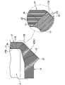
図1に示すように、熱交換器1は、隔壁3、板状の複数のフィン5、ピン状の複数のフィン7(以下、ピン状フィン7という。)、及びシェル9を主として備える。熱交換器1は、隔壁3によって仕切られた温度の異なる二流体(第1流体、第2流体)の間接的な接触によりそれらの熱交換を行う。 As shown in FIG. 1 , the
隔壁3は、有底筒体として熱交換器1の胴体を構成する。隔壁3は、略円筒状をなす側周部11と、その側周部11の一方(ここでは、下側)の開口を閉鎖するように設けられた底部13と、を有する。隔壁3の内側には、加熱対象となる比較的低温の液体を含む第1流体14(例えば、常温の水)が注入される。また、隔壁3の外側には、第1流体よりも高温の気体を含む第2流体15(ここでは、図示しない燃焼器からの高温の燃焼ガス)が流れる。 The
隔壁3は、フィン5及びピン状フィン7と一体をなす一体成形品である。隔壁3、フィン5、及びピン状フィン7は、同一の金属材料(ここでは、アルミニウム)からなる。 The
隔壁3の外面(一方の面)3Aには、複数のフィン5が形成されている。各フィン5は、図2にも示すように、その長手方向において隔壁3の側周部11から底部13に渡って延在する。各フィン5は、側周部11の外面に接続された内縁を有する側部(第1の部分)17と、底部13の外面に接続された内縁を有する基部(第2の部分)19とを含む。 A plurality of
本実施形態では、複数のフィン5は、2種類のフィンからなる。より詳細には、図1に示すように、複数のフィン5には、基部19が比較的長いフィンおよび基部19が比較的短いフィンが含まれる。以下、それらの区別が必要な場合には、それぞれ長フィン5Lおよび短フィン5Sと称する。また、長フィン5Lおよび短フィン5Sをそれぞれ構成する部分についても、必要に応じて符号に「L」及び「S」を付加して区別する。 In this embodiment, the plurality of
各フィン5は、側周部11の周方向に対して交差または略直交するように配置される対をなす伝熱面21、21(主伝熱面)を有する。複数のフィン5は、図3にも示すように、側周部11の全周に渡ってその周方向(すなわち、対をなす伝熱面21、21に交差する方向)に互いに間隔をおいて配列される。長フィン5Lおよび短フィン5Sは、周方向に交互に配置される。 Each
図4に示すように、各フィン5における側部17は、隔壁3の側周部11に沿うように、基部19の上縁から斜め上方に向かって(すなわち、長手方向において)らせん状に湾曲した部位を構成する。このように、各フィン5の少なくとも一部を湾曲させることにより、複数のフィン5の表面近傍における流体の流れをより円滑にする(流体の流速を増大させる)ことができる。 As shown in FIG. 4 , the
各フィン5の側部17の幅(外縁17Aと内縁17Bとの距離)は、長手方向における略全域に渡って略同一である(図1参照)。ただし、側部17の上縁17Cは、側面視において隔壁3の外面3Aと鋭角をなすように形成される。なお、側部17は、その少なくとも一部が湾曲した部位(すなわち、伝熱面としての曲面が形成された部位)を構成すればよい。また、湾曲した部位は、らせん状に限らず、少なくとも曲面を有するものであればよい。 The width of the
図5に示すように、各フィン5の側部17は、長手方向に直交する断面(図2中のV-V線断面)において、その内縁17Bから外縁17Aに向けて先細り状をなすように構成される。隣接するフィン5の間のスペース(すなわち、隣接する伝熱面21の間のスペース)は、内側(隔壁3側)から外側に向けて徐々に拡大する。これにより、隣接するフィン5の間における流体のよどみを抑制することができる。 As shown in FIG. 5, the
側部17における対をなす伝熱面21、21には、内縁17Bから外縁17Aに向けて所定の間隔で配列された複数の溝25が形成されている。熱交換効率を向上させる観点から、複数の溝25の深さD(伝熱面21、21に略直交する各フィン5の厚み方向の深さ)は、100μm~400μmに設定されるとよい。同様に、複数の溝25の幅Wは、深さDの2倍程度(200μm~800μm)に設定されるとよい。同様に、隣接する溝25の間隔Lは、100μm~300μmに設定されるとよい。なお、溝25は、少なくとも一方の伝熱面21に形成されればよい。 A plurality of
各フィン5の基部19は、その長手方向に(底面視において)略直線状をなす。基部19は、側部17の下縁17D(図6参照)から隔壁3の底部13に沿うように延在する。基部19は、側面視において、下方に突設されかつ略直角の頂部を有する突部31を有する。図示は省略するが、基部19は、側部17と同様に、その内縁から外縁に向けて先細り状をなすように構成される。 The
基部19における対をなす伝熱面21、21には、側部17と同様に複数の溝125が形成されるが、それらの溝125の延在方向は、側部17の溝25とは異なる。より詳細には、図6に示すように、側部17の溝25は、隔壁3の側周部11における外面3A(側周面)に沿うように長手方向(ここでは、略上下方向)にそれぞれ延在する。一方、基部19の溝125は、隔壁3の底部13における外面3A(底面)に向けて(ここでは、上方に向けて左側に傾いた方向に)それぞれ延在する。なお、各溝125の深さ、幅、及び間隔については、側部17の溝25と同様に設定され得る。 A plurality of
このように、有底筒体の底面付近の第2流体を、複数の溝125によってその底面に向けて流れるように導くことにより、有底筒体の底部13での熱伝達を促進し、また、有底筒体の側周面付近の第2流体を、複数の溝25によって側周面に沿って流れるように導くことにより、有底筒体の側周11部での熱伝達を促進できる。 In this way, by guiding the second fluid near the bottom surface of the bottomed cylinder toward the bottom surface by means of the plurality of
なお、本実施形態では、隔壁3が有底筒体を構成するため、各フィン5が基部19を有する例を示すが、隔壁3が他の構造(例えば、管状体)を構成する場合には、基部19は省略され得る。 In this embodiment, since the
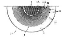
図7に示すように、隔壁3の底部13では、周方向に隣接する長フィン5Lの間にそれぞれ配置された複数の板状部材35が設けられている。各板状部材35は、略矩形状をなす(図1参照)。各板状部材35は、底面視において、短フィン5Sにおける短い基部19Bの終端(内縁)の延長線上(すなわち、径方向)に延在する。したがって、複数の板状部材35は、短フィン5Sと同数設けられる。 As shown in FIG. 7, the
各板状部材35の内縁は、周方向において長フィン5Lの基部19Aの内縁と略同一の位置にある。これにより、隔壁3の底部13では、複数の長フィン5Lの基部19Aおよび複数の板状部材35の内縁によって、複数のピン状フィン7が配置される略円形の領域が画定される。なお、長フィン5Lの基部19Aは、底面視において(または水平断面で見た場合に)、径方向内側に向けて先細り状をなすように形成されるとよい。 The inner edge of each plate-
各板状部材35は、フィン5を構成する金属材料(ここでは、アルミニウム)よりも高い放射率を有する他の金属材料(ここでは、ステンレス)からなる。図1に示すように、複数の板状部材35は、隔壁3の底部13における外面3Aに形成された複数の取付け溝37にそれぞれ嵌め込まれる。なお、板状部材35を構成する材料については、ステンレスに限らず、少なくともフィン5を構成する金属材料よりも高い放射率を有するものであればよい。 Each
図8に示すように、各ピン状フィン7は、先細り状をなす円柱状(または円錐状)状をなす。各ピン状フィン7の周面には、長手方向(突出方向)に延びる複数の突条41が形成されている。複数の突条41は、周方向に所定の間隔をおいて配置されている。 As shown in FIG. 8, each pin-
そのような複数の突条41により各ピン状フィン7の表面積が増大する。また、複数の突条41が、先細り状をなすピン状フィン7に形成されることにより、ピン状フィン7の表面付近に形成される温度境界層の厚みを低減する効果も得られる。その結果、隔壁3の内側の第1流体14への熱抵抗が減少し、また、第1流体の対流伝熱が促進される。 The surface area of each pin-
隔壁3の内面(他方の面)3Bには、未封孔のアルマイト皮膜が形成されている。アルマイト皮膜には、10nm~30nmの孔径をそれぞれ有する複数の細孔が形成されている。これにより、熱交換器1では、隔壁3の外面3Aに形成されたフィン5によって、第2の流体と隔壁3との熱伝達を促進しつつ、隔壁3の内面3Bに形成された細孔によって、第1の流体と隔壁3との熱伝達を促進することができる。ただし、そのようなアルマイト皮膜は省略されてもよい。また、アルマイト皮膜は、隔壁3の内面3Bの一部(例えば、底部13の内面13B)にのみ形成されてもよい。 An unsealed alumite film is formed on the inner surface (the other surface) 3B of the
シェル9は、略筒状をなし、図1に示すように複数のフィン5の外側を覆うように設けられる。これにより、シェル9の内面9Aと隔壁3の外面3Aとによって第2流体15の流路が画定され、その流路内に内複数のフィン5が位置する。 The
シェル9は、複数のフィン5において隔壁3とは反対側に位置する外縁部に接続される上部51と、上部51の下縁に接続され、下方に延在する下部53とを有する。上部51の下縁51Aは、各フィン5の基部19における突部31の角に接続される。下部53は、ピン状フィン7の更に外方(ここでは、下方)に位置し、略円形状をなす開口55を有している。開口55は、第2流体15の入口を構成する。このようなシェル9により、有底筒体に設けられたフィン5に対して第2流体を効率的に導くことが可能となる。 The
上述のような構成を有する熱交換器1の製造では、隔壁3、複数のフィン5、及び複数のピン状フィン7は、公知の3Dプリンティング技術による積層造形(Additive Manufacturing)に基づき一体成形される。積層造形に用いられる加工方式については、上述のような構造を実現可能な限りにおいて特に限定されない。例えば、熱交換器1は、金属粉末およびレーザ(または電子ビーム)を造形部位に同時に照射し、溶融した金属粉末を上述のような形状に積層することによって成形される。 In manufacturing the
シェル9は、隔壁3等と共に一体成形されてもよい。或いは、シェル9は、隔壁3を構成する金属材料とは異なる他の金属材料によって形成された後に、複数のフィン5の外側を覆うように溶接等によって取り付けられてもよい。 The
隔壁3の内面3Bにおける未封孔のアルマイト皮膜は、公知のアルマイト加工(アルミニウムの陽極酸化処理)によって形成される。アルマイト皮膜における複数の細孔の構造(孔径等)については、例えば、電界放出型走査電子顕微鏡(FE-SEM)を用いて確認することができる。 The unsealed alumite film on the
ユーザは、熱交換器1の使用時には、例えば、隔壁3の内側に第1流体としての水を注入した後、熱交換器1の下方に配置されて燃焼器(例えば、ガスバーナー)を稼働させる。これにより、第2流体としての燃焼器の燃焼ガスがシェル9の開口55から導入される。燃焼ガスは、隔壁3とシェル9との間に位置する複数のフィン5の間を流れ、開放されたシェル9の上部から排出される。このとき、燃焼ガスの熱が、隔壁3、フィン5、及びピン状フィン7に伝達され、隔壁3の内面3Bを介して第1流体に伝達される。このような燃焼ガスと水との熱交換により、隔壁3内の水の温度を上昇させる(最終的に沸騰させる)ことができる。 When using the
このように、熱交換器1では、隔壁3および複数のフィン5を一体成形することにより、隔壁3とフィン5との界面における熱抵抗を低減し、また、湾曲した部位(ここでは、側部17)を有する複数のフィン5に適切な深さの溝を形成することにより、フィン5の伝熱面積を増大させつつ、フィン5の表面近傍における第2流体の流れを円滑にすることができる。その結果、熱交換器1の熱交換効率を向上させることが可能となる。 Thus, in the
以上で具体的実施形態の説明を終えるが、本発明は上記実施形態に限定されることなく幅広く変形実施することができる。 Although the specific embodiments have been described above, the present invention is not limited to the above embodiments and can be widely modified.
熱交換器1の隔壁3については、有底筒体に限定されず、公知の熱交換器に用いられる種々の形状が採用され得る。例えば、隔壁3は、第1流体および第2流体を仕切る管状体を構成してもよい。その場合、第1流体は、隔壁3の内側を所定の方向に流れる。また、熱交換器1においてフィン5は、隔壁3の外面3Aおよび内面3Bの少なくとも一方に形成されればよい。 The
また、第1流体及び第2流体は、液体及び気体の組み合わせである必要はなく、任意の流体の組み合わせ(例えば、液体同士または気体同士の組み合わせ)が採用されうる。また、熱交換器1は、少なくとも二流体を用いるものであればよく、三流体以上を用いて熱交換が行われてもよい。 Also, the first fluid and the second fluid need not be a combination of liquid and gas, and any combination of fluids (for example, a combination of liquids or gases) may be employed. Moreover, the
また、熱交換器1では、隔壁3と一体成形されるフィン5に用いられる金属材料に制約がある(例えば、積層造形に用いることが可能な金属材料が限られる)場合でも、より高い放射率を有する板状部材35によって熱放射(輻射伝熱)を高めることにより、熱交換器1における流体温度の均一性を向上させ、また、熱交換効率を向上させることができる。 In addition, in the
熱交換器1の用途としては、例えば、冷蔵庫及び産業用熱交換器や、プレート型熱交換器、パイプ状通路式熱交換器が挙げられる。また、熱交換器1は、隔壁及びフィンを有することにより熱交換器として機能する装置や機械の一部としても用いられ得る。そのような熱交換器1の用途としては、例えば、空冷エンジンヘッド、ラジエター、オイルクーラー、湯沸かし器、空調設備、EGRクーラー、及びスターリングエンジンなどの流体通路構造などが挙げられる。 Applications of the
1 :熱交換器
3 :隔壁
3A :外面
3B :内面
5 :フィン
5L :長フィン
5S :短フィン
7 :ピン状フィン
9 :シェル
9A :内面
11 :側周部
13 :底部
13B:内面
14 :第1流体
15 :第2流体
17 :側部(第1の部分)
17A:外縁
17B:内縁
17C:上縁
17D:下縁
19 :基部(第2の部分)
19A:基部
19B:基部
21 :伝熱面
25、125:溝
31 :突部
35 :板状部材
37 :取付け溝
41 :突条
51 :上部
51A:下縁
53 :下部
55 :開口1: heat exchanger 3:
17A:
19A: Base 19B: Base 21:
Claims (9)
Translated fromJapanese温度の異なる二流体を隔てる隔壁と、
前記隔壁の少なくとも一方の面に形成され、対をなす伝熱面を有する板状の複数のフィンと、を備え、
前記隔壁および前記複数のフィンは、同一の金属材料からなる一体成形品であり、
前記複数のフィンは、湾曲した部位を有すると共に、前記対をなす伝熱面に交差する方向に互いに間隔をおいて配列され、
前記対をなす伝熱面には、前記各フィンの厚み方向に100μm~400μmの深さの複数の溝が形成された、熱交換器。a heat exchanger,
a partition separating two fluids with different temperatures;
a plurality of plate-shaped fins formed on at least one surface of the partition wall and having paired heat transfer surfaces;
The partition wall and the plurality of fins are integrally molded products made of the same metal material,
the plurality of fins have curved portions and are arranged at intervals in a direction intersecting the pair of heat transfer surfaces;
A heat exchanger in which a plurality of grooves having a depth of 100 μm to 400 μm are formed in the pair of heat transfer surfaces in the thickness direction of each fin.
前記複数のフィンは、前記有底筒体の外面を構成する底面および側周面にそれぞれ接続され、
前記有底筒体の前記底面に接続された前記各フィンの第1の部分では、前記複数の溝は、前記底面に向けてそれぞれ延在し、
前記有底筒体の前記側周面に接続された前記各フィンの第2の部分では、前記複数の溝は、前記側周面に沿うようにそれぞれ延在する、請求項1から請求項3のいずれか1項に記載の熱交換器。The partition constitutes a cylinder with a bottom,
the plurality of fins are respectively connected to a bottom surface and a side peripheral surface forming an outer surface of the bottomed cylindrical body,
in a first portion of each fin connected to the bottom surface of the bottomed cylinder, the plurality of grooves each extend toward the bottom surface;
Claims 1 to 3, wherein in the second portion of each of the fins connected to the side peripheral surface of the bottomed cylinder, the plurality of grooves extend along the side peripheral surface. The heat exchanger according to any one of .
温度の異なる二流体を隔てる隔壁と、前記隔壁の少なくとも一方の面に形成され、対をなす伝熱面を有する板状の複数のフィンと、を積層造形に基づき同一の金属材料によって一体成形し、
前記複数のフィンは、湾曲した部位を有すると共に、前記対をなす伝熱面に交差する方向に互いに間隔をおいて配列され、
前記対をなす伝熱面には、前記各フィンの厚み方向に100μm~400μmの深さの複数の溝が形成された熱交換器の製造方法。A method for manufacturing a heat exchanger,
A partition wall separating two fluids having different temperatures and a plurality of plate-shaped fins having heat transfer surfaces that are formed on at least one surface of the partition wall and have paired heat transfer surfaces are integrally molded from the same metal material based on layered manufacturing. ,
the plurality of fins have curved portions and are arranged at intervals in a direction intersecting the pair of heat transfer surfaces;
A method for manufacturing a heat exchanger, wherein a plurality of grooves having a depth of 100 μm to 400 μm are formed in the pair of heat transfer surfaces in the thickness direction of each fin.
Priority Applications (3)
| Application Number | Priority Date | Filing Date | Title |
|---|---|---|---|
| JP2021053434AJP7229292B2 (en) | 2021-03-26 | 2021-03-26 | Heat exchanger and manufacturing method thereof |
| CN202210137303.2ACN115127366A (en) | 2021-03-26 | 2022-02-15 | Heat exchanger and method for manufacturing heat exchanger |
| US17/673,963US11774188B2 (en) | 2021-03-26 | 2022-02-17 | Heat exchanger and manufacturing method thereof |
Applications Claiming Priority (1)
| Application Number | Priority Date | Filing Date | Title |
|---|---|---|---|
| JP2021053434AJP7229292B2 (en) | 2021-03-26 | 2021-03-26 | Heat exchanger and manufacturing method thereof |
Publications (2)
| Publication Number | Publication Date |
|---|---|
| JP2022150714Atrue JP2022150714A (en) | 2022-10-07 |
| JP7229292B2 JP7229292B2 (en) | 2023-02-27 |
Family
ID=83364455
Family Applications (1)
| Application Number | Title | Priority Date | Filing Date |
|---|---|---|---|
| JP2021053434AActiveJP7229292B2 (en) | 2021-03-26 | 2021-03-26 | Heat exchanger and manufacturing method thereof |
Country Status (3)
| Country | Link |
|---|---|
| US (1) | US11774188B2 (en) |
| JP (1) | JP7229292B2 (en) |
| CN (1) | CN115127366A (en) |
Cited By (1)
| Publication number | Priority date | Publication date | Assignee | Title |
|---|---|---|---|---|
| JP2024057210A (en)* | 2022-10-12 | 2024-04-24 | 本田技研工業株式会社 | Laminated object assembly |
Citations (5)
| Publication number | Priority date | Publication date | Assignee | Title |
|---|---|---|---|---|
| JPS57175887A (en)* | 1981-04-24 | 1982-10-28 | Toshiba Corp | Heat exchanger |
| JPH0741268U (en)* | 1993-12-06 | 1995-07-21 | 株式会社神戸製鋼所 | Open rack type liquefied low temperature gas vaporizer heat transfer tube |
| JP2006132839A (en)* | 2004-11-05 | 2006-05-25 | Mitsubishi Electric Corp | Heat exchanger and manufacturing method thereof |
| JP2011054778A (en)* | 2009-09-02 | 2011-03-17 | Furukawa-Sky Aluminum Corp | Heat exchanger using comb-type radiation unit |
| JP2012097920A (en)* | 2010-10-29 | 2012-05-24 | Mitsubishi Electric Corp | Heat exchanger |
Family Cites Families (15)
| Publication number | Priority date | Publication date | Assignee | Title |
|---|---|---|---|---|
| GB375472A (en)* | 1931-04-20 | 1932-06-30 | Gas Light & Coke Co | Improvements in or relating to cooking and like pans |
| DE955355C (en)* | 1954-10-30 | 1957-01-03 | Strebelwerk G M B H | Cast iron convector with ribs and fins for collective heating systems |
| FR2491202B1 (en)* | 1980-10-01 | 1986-02-28 | Air Liquide | ATMOSPHERIC HEATER |
| FR2493125A1 (en)* | 1980-11-05 | 1982-05-07 | Faurie Bernard | Cooking vessel with increased heat exchange area - has radial fins on base extending vertically along cylindrical side walls |
| SE8303189L (en)* | 1983-06-07 | 1984-12-08 | Alutherm Ab | HEAD EXCHANGER OF STRESSED PROFILE |
| US5564589A (en)* | 1995-02-07 | 1996-10-15 | Fu; Hseuh-Chien | Pot or pan |
| JP2005204819A (en)* | 2004-01-21 | 2005-08-04 | Seiko Kikai Kk | Cooking vessel |
| CN100547339C (en)* | 2008-03-12 | 2009-10-07 | 江苏萃隆精密铜管股份有限公司 | A kind of enhanced heat transfer tube and its manufacturing method |
| US8701927B2 (en)* | 2009-02-11 | 2014-04-22 | Massachusetts Institute Of Technology | Nanoparticle thin-film coatings for enhancement of boiling heat transfer |
| US8037602B2 (en)* | 2009-03-27 | 2011-10-18 | Eneron, Inc. | Methods of making energy efficient cookware |
| CN201500001U (en)* | 2009-08-04 | 2010-06-09 | 万广明 | energy saving pot |
| JP5534951B2 (en) | 2010-06-01 | 2014-07-02 | 三菱電機株式会社 | Heat exchanger processing method and heat exchanger |
| GB201212283D0 (en)* | 2012-07-10 | 2012-08-22 | Isis Innovation | Heating vessel |
| JP2017150756A (en) | 2016-02-25 | 2017-08-31 | パナソニックIpマネジメント株式会社 | Heat exchanger and manufacturing method of fin |
| CN207600274U (en)* | 2017-12-11 | 2018-07-10 | 珠海格力电器股份有限公司 | Heat exchange tube, heat exchanger and air conditioner |
- 2021
- 2021-03-26JPJP2021053434Apatent/JP7229292B2/enactiveActive
- 2022
- 2022-02-15CNCN202210137303.2Apatent/CN115127366A/enactivePending
- 2022-02-17USUS17/673,963patent/US11774188B2/enactiveActive
Patent Citations (5)
| Publication number | Priority date | Publication date | Assignee | Title |
|---|---|---|---|---|
| JPS57175887A (en)* | 1981-04-24 | 1982-10-28 | Toshiba Corp | Heat exchanger |
| JPH0741268U (en)* | 1993-12-06 | 1995-07-21 | 株式会社神戸製鋼所 | Open rack type liquefied low temperature gas vaporizer heat transfer tube |
| JP2006132839A (en)* | 2004-11-05 | 2006-05-25 | Mitsubishi Electric Corp | Heat exchanger and manufacturing method thereof |
| JP2011054778A (en)* | 2009-09-02 | 2011-03-17 | Furukawa-Sky Aluminum Corp | Heat exchanger using comb-type radiation unit |
| JP2012097920A (en)* | 2010-10-29 | 2012-05-24 | Mitsubishi Electric Corp | Heat exchanger |
Cited By (1)
| Publication number | Priority date | Publication date | Assignee | Title |
|---|---|---|---|---|
| JP2024057210A (en)* | 2022-10-12 | 2024-04-24 | 本田技研工業株式会社 | Laminated object assembly |
Also Published As
| Publication number | Publication date |
|---|---|
| CN115127366A (en) | 2022-09-30 |
| JP7229292B2 (en) | 2023-02-27 |
| US20220307775A1 (en) | 2022-09-29 |
| US11774188B2 (en) | 2023-10-03 |
Similar Documents
| Publication | Publication Date | Title |
|---|---|---|
| RU2742365C2 (en) | Heat exchanger | |
| US20200189046A1 (en) | Locomotive heat exchanger apparatus and method of manufacturing a heat exchanger apparatus | |
| TWI455461B (en) | Cooling jacket | |
| JP6290415B2 (en) | Heat exchanger and method for manufacturing the heat exchanger | |
| CN1158409A (en) | heat exchanger | |
| CN102713491A (en) | Heat exchanger, a food handler including the heat exchanger, and a manufacturing method of the heat exchanger | |
| KR20170063543A (en) | Corrugated fins for heat exchanger | |
| JP7229292B2 (en) | Heat exchanger and manufacturing method thereof | |
| JP2008261566A (en) | Double tube heat exchanger | |
| JP2008145024A (en) | Manufacturing method of flat heat transfer tube, flat heat transfer tube obtained by method, and gas cooling device incorporating flat heat transfer tube | |
| CN104482792B (en) | A kind of axial symmetry type intersection inner fin thermoexcell | |
| JP2016524122A (en) | Heat transfer tube | |
| US20080078534A1 (en) | Heat exchanger tube with enhanced heat transfer co-efficient and related method | |
| JP7739249B2 (en) | Heat exchanger and manufacturing method thereof | |
| US12352508B2 (en) | Heat exchanger and method for manufacturing same | |
| US12287158B2 (en) | Heat exchanger and method for manufacturing same | |
| JP7229986B2 (en) | heat exchanger tank structure | |
| CN106949770A (en) | Radiator and its efficient cooling tube | |
| CN111895842A (en) | Heat Exchanger Tubes, Air Conditioning Heat Exchangers and Air Conditioning Equipment of Air Conditioning Heat Exchangers | |
| JP2010255864A (en) | Flat tube and heat exchanger | |
| JP2023152617A (en) | Heat exchanger and method for manufacturing the same | |
| JP2013088010A (en) | U-turn heat exchanger | |
| RU181284U1 (en) | Pipe arrangement for heat exchangers | |
| EP3521746A1 (en) | A flat tube for a heat exchanger | |
| JP6764765B2 (en) | Heat transfer member |
Legal Events
| Date | Code | Title | Description |
|---|---|---|---|
| A621 | Written request for application examination | Free format text:JAPANESE INTERMEDIATE CODE: A621 Effective date:20211129 | |
| A131 | Notification of reasons for refusal | Free format text:JAPANESE INTERMEDIATE CODE: A131 Effective date:20230110 | |
| A521 | Request for written amendment filed | Free format text:JAPANESE INTERMEDIATE CODE: A523 Effective date:20230124 | |
| TRDD | Decision of grant or rejection written | ||
| A01 | Written decision to grant a patent or to grant a registration (utility model) | Free format text:JAPANESE INTERMEDIATE CODE: A01 Effective date:20230207 | |
| A61 | First payment of annual fees (during grant procedure) | Free format text:JAPANESE INTERMEDIATE CODE: A61 Effective date:20230214 | |
| R150 | Certificate of patent or registration of utility model | Ref document number:7229292 Country of ref document:JP Free format text:JAPANESE INTERMEDIATE CODE: R150 |