JP2022150289A - Obstacle information providing device - Google Patents
Obstacle information providing deviceDownload PDFInfo
- Publication number
- JP2022150289A JP2022150289AJP2021052836AJP2021052836AJP2022150289AJP 2022150289 AJP2022150289 AJP 2022150289AJP 2021052836 AJP2021052836 AJP 2021052836AJP 2021052836 AJP2021052836 AJP 2021052836AJP 2022150289 AJP2022150289 AJP 2022150289A
- Authority
- JP
- Japan
- Prior art keywords
- vehicle
- information
- obstacle information
- obstacle
- load
- Prior art date
- Legal status (The legal status is an assumption and is not a legal conclusion. Google has not performed a legal analysis and makes no representation as to the accuracy of the status listed.)
- Pending
Links
Images


Landscapes
- Fittings On The Vehicle Exterior For Carrying Loads, And Devices For Holding Or Mounting Articles (AREA)
- Traffic Control Systems (AREA)
Abstract
Translated fromJapaneseDescription
Translated fromJapanese本発明は、車両に搭載される障害物情報提供装置に関する。 The present invention relates to an obstacle information providing device mounted on a vehicle.
従来、車両に搭載される装置として、例えば、特開平08-238976号公報に記載されるように、車両に搭載された荷物の落下を監視する装置が知られている。この装置は、荷物室に積まれた荷物を撮像するカメラを備え、カメラの画像の変化に応じ荷物の落下などを検出し警報を発するものである。 2. Description of the Related Art Conventionally, as a device mounted on a vehicle, there has been known a device for monitoring the fall of luggage mounted on the vehicle, as described in Japanese Patent Application Laid-Open No. 08-238976, for example. This device is equipped with a camera for picking up images of luggage stacked in the luggage compartment, and detects the falling of the luggage according to changes in the image of the camera and issues an alarm.
ところで、車両から荷物が落下すると、この荷物は走行路上の障害物となる可能性がある。このため、走行路上の荷物が他の車両の走行の支障となり、車両の走行安全性が損なわれるおそれがある。 By the way, if a load falls from a vehicle, this load may become an obstacle on the road. As a result, the luggage on the road may hinder the travel of other vehicles, and the travel safety of the vehicle may be impaired.
そこで、本発明は、車両走行の安全性を高めることができる障害物情報提供装置を提供することを目的とする。 SUMMARY OF THE INVENTION Accordingly, it is an object of the present invention to provide an obstacle information providing apparatus capable of enhancing the safety of vehicle travel.
すなわち、本発明に係る障害物情報提供装置は、車両に搭載され車両の荷台に積まれる積荷の落下を検出する落下検出部と、車両に搭載され落下検出部により前記積荷の落下が検出された場合に積荷の落下情報を障害物情報として情報提供する情報提供部とを備えて構成される。この障害物情報提供装置によれば、車両の荷台に積まれる積荷の落下を検出し、積荷の落下情報を障害物情報として情報提供する。このため、障害物が発生した時から障害物情報を早期に提供することができる。従って、この障害物情報を用いることにより車両走行の安全性を高めることができる。 That is, the obstacle information providing apparatus according to the present invention includes a drop detection unit mounted on a vehicle for detecting a drop of a load loaded on the vehicle bed, and a drop detection unit mounted on the vehicle for detecting the drop of the load. and an information providing unit that provides information on the falling of the cargo as obstacle information in the event of a failure. According to this obstacle information providing device, the fall of the cargo loaded on the platform of the vehicle is detected, and information on the fall of the cargo is provided as obstacle information. Therefore, obstacle information can be provided early from the time when an obstacle occurs. Therefore, by using this obstacle information, the safety of vehicle travel can be enhanced.
また、本発明に係る障害物情報提供装置において、車両はダンプトラックであり、情報提供部は車両が走行する工事現場において車両の走行制御を行う制御機器に対し情報提供を行ってもよい。この場合、工事現場において積荷の落下による障害物情報を早期に情報提供することができる。このため、工事現場を走行する車両の走行安全性を高めることができる。 Further, in the obstacle information providing apparatus according to the present invention, the vehicle may be a dump truck, and the information providing section may provide information to a control device that controls travel of the vehicle at a construction site where the vehicle travels. In this case, it is possible to promptly provide information on obstacles due to falling loads at the construction site. Therefore, it is possible to improve the running safety of the vehicle running on the construction site.
本発明によれば、車両走行の安全性を高めることができる障害物情報提供装置を提供することができる。 ADVANTAGE OF THE INVENTION According to this invention, the obstacle information provision apparatus which can improve the safety of vehicle driving|running|working can be provided.
以下、図面を参照して、本発明の実施形態について説明する。なお、以下の説明において、同一又は相当要素には同一符号を付し、重複する説明を省略する。 Hereinafter, embodiments of the present invention will be described with reference to the drawings. In the following description, the same or corresponding elements are denoted by the same reference numerals, and overlapping descriptions are omitted.
図1は、本発明の実施形態に係る障害物情報提供装置1が搭載される車両9の説明図である。図2は、本実施形態に係る障害物情報提供装置1の電気的な構成概要を示すブロック図である。図1に示すように、障害物情報提供装置1は、車両9に搭載され、車両9の走行路における障害物情報を提供する装置である。車両9は、運搬車両であり、例えばダンプトラックである。車両9は、キャビン92の後方に荷台91を備えており、荷台91に対し積荷93を積み込むことができる。車両9としては、無人走行を行える車両が用いられる。例えば、車両9は、工事現場で積荷93を運搬して走行する無人走行ダンプとして用いられる。この車両9は、予め設定された経路に沿って自動走行する車両であってもよいし、遠隔操作により走行する車両であってもよい。また、車両9は、遠隔操作又は自動制御によって荷台91を傾斜させて荷下ろし行う車両であってもよい。 FIG. 1 is an explanatory diagram of a
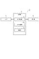
図2に示すように、障害物情報提供装置1は、センサ2、制御部3及び通信部4を備えている。センサ2、制御部3及び通信部4は、それぞれ車両9に搭載されている。例えば、センサ2及び通信部4はキャビン92の上部に設置され、制御部3は、キャビン92の内部又はその下方に設置される。センサ2は、荷台91から積荷93の落下を検知するセンサである。センサ2は、積荷93の落下を検知できるものであればいずれのタイプのセンサであってもよい。例えば、センサ2として、荷台91及び車両9の後方を撮像可能なカメラ、レーザ光を用い荷台91及び車両9の後方を検知するライダ(LiDAR)、又は荷台91の積載重量を検知する重量検知センサなどが用いられる。 As shown in FIG. 2, the obstacle
センサ2としてカメラを用いる場合、図1に示すように、センサ2によって荷台91及び車両9の後方が撮像される。そして、撮像画像の画像処理することによって荷台91上の積荷93の変化が検出され、走行路上における積荷93が検出される。これにより、積荷93の落下を検出することができる。 When a camera is used as the
センサ2としてライダを用いる場合、図1に示すように、センサ2によって荷台91及び車両9の後方の領域にレーザ光が照射される。そして、レーザ光の反射光を検出解析することよって荷台91上の積荷93の変化が検出され、走行路上における積荷93が検出される。これにより、積荷93の落下を検出することができる。 When a lidar is used as the
センサ2として重量検知センサを用いる場合、センサ2によって荷台91の積載重量が検知される。そして、積載重量の変化の検出により積荷93の落下を検出することができる。なお、センサ2は、カメラ、ライダ及び重量検知センサ以外のものを用いてもよい。センサ2は、制御部3に電気的に接続されており、検知信号を制御部3へ出力する。 When a weight detection sensor is used as the
制御部3は、障害物情報提供装置1の制御を行う電子制御ユニットであり、CPU[Central Processing Unit]、ROM[Read Only Memory]、RAM[Random Access Memory]を含むコンピュータにより構成されている。制御部3の詳細については、後述する。 The
通信部4は、障害物情報提供装置1の外部と無線通信するための通信機器であり、積荷93の落下情報を障害物情報として情報提供する情報提供部として機能する。すなわち、通信部4は、積荷93の落下が検出された場合に積荷93の落下情報を含む障害物情報信号を送信する。図3に示すように、通信部4は、例えば遠隔操作機器8との通信を行う。遠隔操作機器8は、車両9を遠隔操作するための機器であって通信機能を有し、操作者によって操作される。例えば、遠隔操作機器8は、工事現場又は工事現場から離れた場所に設けられる管理施設81に設置され、車両9の走行制御を行う制御機器として機能する。すなわち、遠隔操作機器8は、車両9が走行する経路を設定し、その経路に沿って車両9が走行するように指令を出して車両9の走行制御を行う。 The
図2に示すように、通信部4は、制御部3と電気的に接続しており、障害物情報を含む障害物情報信号を入力し、遠隔操作機器8へこの障害物情報信号を送信する。障害物情報は、積荷93の落下情報を障害物の情報としたものである。落下情報は、積荷93の落下があったという情報を含む。また、落下情報は、積荷93の落下位置情報、積荷93の種類情報及び積荷93の落下量情報のうち、その一部又は全部を含んでもよい。積荷93の落下位置情報は、積荷93の落下の位置を示す情報であり、例えば車両9の位置情報(例えばGPS機器の検出情報)に基づいて取得される。積荷93の種類情報は、落下した積荷93の種類を示す情報であり、例えば遠隔操作機器8における入力情報に基づいて取得される。落下量情報は、落下した積荷93の量又は数を示す情報であり、例えばセンサ2の検出情報に基づいて取得される。また、障害物情報は、落下情報そのままの情報であってもよいし、障害物の情報に変換したものであってもよい。例えば、障害物情報は、障害物が発生したという情報、障害物位置情報、障害物の種類の情報及び障害物の大きさの情報という形式で送信されてもよい。障害物が発生したという情報は積荷93の落下があったという情報に対応しており、障害物位置情報は積荷93の落下位置情報に対応しており、障害物の種類の情報は積荷93の種類情報に対応しており、障害物の大きさの情報は積荷93の落下量情報に対応している。遠隔操作機器8は、障害物情報信号を受信し、障害物情報を用いて車両9やその他の車両の走行経路を生成又は修正して車両走行制御を行う。 As shown in FIG. 2, the
制御部3は、落下検出部31、出力制御部32及び記録部33を備えている。落下検出部31及び出力制御部32は、それぞれの機能を実行するソフトウェア又はプログラムを制御部3に導入することによって構成すればよい。また、落下検出部31及び出力制御部32のうち全部又は一部を個別の制御器として設置してもよい。また、制御部3は、車両9の制御を行う走行制御部としての機能を備えていてもよい。 The
落下検出部31は、センサ2の検知信号に基づいて荷台91の積荷93の落下の検出を行う。すなわち、落下検出部31は、センサ2の検知信号に基づいて荷台91から積荷93が落下したか否かの判定を行って積荷93の落下の検出を行う。例えば、センサ2としてカメラが用いられる場合、センサ2により撮像された荷台91及び車両9の後方の画像情報が所定時間ごとに取得され、画像の変化に基づいて積荷93の落下が検出される。また、センサ2としてライダが用いられる場合、センサ2により荷台91及び車両9の後方の領域にレーザ光を照射し、その反射光を検出解析することよって荷台91上の積荷93の形状の変化、車両9の後方の走行路の形状の変化により積荷93の落下が検出される。センサ2として重量検知センサが用いられる場合、センサ2による荷台91の積載重量値の変化により積荷93の落下が検出される。なお、落下検出部31において、積荷93が落下した場合であっても車両走行に支障を来さない程度の落下量である場合、積荷93は落下していないと判定してもよい。言い換えれば、落下検出部31において、車両走行に支障を来す程度に積荷93が落下した場合に、積荷93が落下したと判定してもよい。 The
出力制御部32は、落下検出部31により積荷93が落下したと判定された場合に障害物情報を出力する。すなわち、出力制御部32は、通信部4に対し障害物情報を含む障害物情報信号を出力する。記録部33は、障害物情報提供の制御に関するデータなどを記録する。 The
次に本実施形態に係る障害物情報提供装置1の動作について説明する。 Next, the operation of the obstacle
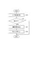
図4は、本実施形態に係る障害物情報提供装置1の動作を示すフローチャートである。このフローチャートは、例えば、車両9に電源が投入されることにより開始され、制御部3によって繰り返し実行される。 FIG. 4 is a flow chart showing the operation of the obstacle
まず、図4のステップS10(以下、単に「S10」という。それ以外のステップSについても同様とする。)に示すように、センサ2の検出値の読み込み処理が行われる。すなわち、制御部3に対しセンサ2の検知信号が入力され記録される。そして、S12に処理が移行し、積荷93が落下したか否かが判定される。すなわち、落下検出部31は、センサ2の検知信号に基づいて荷台91から積荷93が落下したか否かを判定する。例えば、センサ2としてカメラが用いられる場合、センサ2により撮像された荷台91及び車両9の後方の走行路85の画像に基づいて荷台91から積荷93が落下したか否かが判定される。また、センサ2としてライダが用いられる場合、センサ2により検出された荷台91及び車両9の後方の領域の形状に基づいて荷台91から積荷93が落下したか否かが判定される。また、センサ2として重量検知センサが用いられる場合、センサ2により検出される積載重量値に基づいて荷台91から積荷93が落下したか否かが判定される。このS12にて積荷93が落下していないと判定された場合、図4の一連の制御処理を終了する。この場合、再度、図4の一連の制御処理がS10から実行されることとなる。 First, as shown in step S10 of FIG. 4 (hereinafter simply referred to as "S10"; the same applies to the other steps S), the process of reading the detected value of the
一方、S12にて積荷93が落下したと判定された場合、障害物情報の記録処理(S14)、障害物情報の出力処理(S16)が実行される。障害物情報の記録処理は、積荷93の落下情報を障害物情報として記録する処理である。障害物情報は、記録部33に記録される。障害物情報は、例えば落下情報をそのまま障害物情報として記録されてもよいし、障害物の情報として変換されて記録されてもよい。例えば、積荷93の落下があったという情報を障害物が発生したという情報とし、落下位置情報を障害物位置情報とし、積荷93の種類情報を障害物の種類情報とし、積荷93の落下量情報を障害物の大きさ情報として記録されてもよい。 On the other hand, when it is determined in S12 that the
障害物情報の出力処理は、障害物情報を含む障害物情報信号を通信部4に出力する処理である。通信部4は、入力された障害物情報信号を遠隔操作機器8に向けて送信する。これにより、遠隔操作機器8は、障害物情報を受信し、障害物情報を用いて車両9の走行制御を実行する。例えば、図5に示すように、遠隔操作機器8は、車両9の走行路85上の障害物位置Pを認識し、障害物位置Pを回避するように車両の走行経路95を設定し、この走行経路95に沿って車両9およびその他の車両を走行させる。これにより、車両が障害物の影響を受けずに走行することが可能となる。図4のS16の障害物情報の出力処理を終えたら、図4の一連の制御処理を終了する。 The obstacle information output process is a process of outputting an obstacle information signal including obstacle information to the
以上説明したように、本実施形態に係る障害物情報提供装置1によれば、車両9の荷台91に積まれる積荷93の落下を検出し、積荷93の落下情報を障害物情報として情報提供する。このため、障害物が発生した時から障害物情報を早期に提供することができる。従って、この障害物情報を用いることにより車両走行の安全性を高めることができる。 As described above, according to the obstacle
例えば、車両9から積荷93が落下し、その後に落下位置を通過する他の車両が落下した積荷93を発見し障害物情報を提供することが考えられる。この場合、他の車両の走行安全性が損なわれる。また、障害物の発生時から障害物情報の提供までに時間がかかり、障害物情報を早期に提供することができない。これに対し、本実施形態に係る障害物情報提供装置1では、車両9が積荷93の落下を検出した時に障害物情報を情報提供するため、障害物情報を早期に提供することができ、車両走行の安全性を高めることができるのである。 For example, it is conceivable that a
また、本実施形態に係る障害物情報提供装置1において、車両9はダンプトラックであり、通信部4は車両9が走行する工事現場において車両9の走行制御を行う制御機器に対し情報提供を行ってもよい。この場合、工事現場において積荷93の落下による障害物情報を早期に情報提供することができる。このため、工事現場を走行する車両の走行安全性を高めることができる。 Further, in the obstacle
以上のように、本発明の実施形態について説明したが、この実施形態は、本発明に係る障害物情報提供装置の実施形態の一部を説明したものであり、本発明に係る障害物情報提供装置は上記実施形態に記載されたものに限定されない。本発明に係る障害物情報提供装置は、各請求項に記載した要旨を変更しないように上記実施形態に係る障害物情報提供装置を変形し、又は他のものに適用したものであってもよい。 As described above, the embodiment of the present invention has been described, but this embodiment describes a part of the embodiment of the obstacle information providing device according to the present invention. Devices are not limited to those described in the above embodiments. The obstacle information providing device according to the present invention may be modified from the obstacle information providing device according to the above embodiment or applied to other devices without changing the gist of each claim. .
例えば、上述した実施形態に係る障害物情報提供装置1では無人走行する車両9に搭載される場合について説明したが、障害物情報提供装置が搭載される車両は運転者により手動運転される車両であってもよい。また、車両9はダンプトラック以外の車両であってもよい。これらの障害物情報提供装置であっても、上述した障害物情報提供装置1と同様な作用効果を得ることができる。 For example, the obstacle
また、上述した実施形態に係る障害物情報提供装置1では工事現場を走行する車両9に搭載される場合について説明したが、工事現場以外の場所を走行する車両に搭載されていてもよい。例えば、高速道路、自動車専用道路、一般道路などを走行する車両に搭載されてもよい。このような障害物情報提供装置であっても、上述した障害物情報提供装置1と同様な作用効果を得ることができる。 Further, although the obstacle
1…障害物情報提供装置、2…センサ、3…制御部、4…通信部(情報提供部)、8…遠隔操作機器、9…車両、31…落下検出部、32…出力制御部、33…記録部、81…管理施設、85…走行路、91…荷台、92…キャビン、93…積荷、95…走行経路。 DESCRIPTION OF
Claims (2)
Translated fromJapanese前記車両に搭載され、前記落下検出部により前記積荷の落下が検出された場合に前記積荷の落下情報を障害物情報として情報提供する情報提供部と、を備える、
障害物情報提供装置。a drop detection unit mounted on a vehicle for detecting a drop of a cargo loaded on the platform of the vehicle;
an information providing unit mounted on the vehicle for providing information on the fall of the load as obstacle information when the fall of the load is detected by the drop detection unit;
Obstacle information providing device.
前記情報提供部は、前記車両が走行する工事現場において前記車両の走行制御を行う制御機器に対し情報提供を行う、
請求項1に記載の障害物情報提供装置。the vehicle is a dump truck,
The information providing unit provides information to a control device that controls travel of the vehicle at a construction site where the vehicle travels.
The obstacle information providing device according to claim 1.
Priority Applications (1)
| Application Number | Priority Date | Filing Date | Title |
|---|---|---|---|
| JP2021052836AJP2022150289A (en) | 2021-03-26 | 2021-03-26 | Obstacle information providing device |
Applications Claiming Priority (1)
| Application Number | Priority Date | Filing Date | Title |
|---|---|---|---|
| JP2021052836AJP2022150289A (en) | 2021-03-26 | 2021-03-26 | Obstacle information providing device |
Publications (1)
| Publication Number | Publication Date |
|---|---|
| JP2022150289Atrue JP2022150289A (en) | 2022-10-07 |
Family
ID=83464715
Family Applications (1)
| Application Number | Title | Priority Date | Filing Date |
|---|---|---|---|
| JP2021052836APendingJP2022150289A (en) | 2021-03-26 | 2021-03-26 | Obstacle information providing device |
Country Status (1)
| Country | Link |
|---|---|
| JP (1) | JP2022150289A (en) |
Citations (8)
| Publication number | Priority date | Publication date | Assignee | Title |
|---|---|---|---|---|
| WO2014045398A1 (en)* | 2012-09-21 | 2014-03-27 | 日立建機株式会社 | Travel management device of transport vehicle |
| JP2016071566A (en)* | 2014-09-29 | 2016-05-09 | 日立建機株式会社 | Obstacle avoidance system |
| JP2016218576A (en)* | 2015-05-15 | 2016-12-22 | 日立建機株式会社 | Control server and road traffic control system |
| JP2017097482A (en)* | 2015-11-19 | 2017-06-01 | 日立建機株式会社 | Vehicle controller and work machine |
| JP2017116466A (en)* | 2015-12-25 | 2017-06-29 | 日立建機株式会社 | Off-road dump truck and obstacle discrimination device |
| WO2017159639A1 (en)* | 2016-03-14 | 2017-09-21 | 日立建機株式会社 | Mine working machine |
| JP2018043599A (en)* | 2016-09-13 | 2018-03-22 | 日立建機株式会社 | Mine work machine and method of monitoring backward thereof |
| JP2019162893A (en)* | 2018-03-19 | 2019-09-26 | 株式会社デンソー | Control device |
- 2021
- 2021-03-26JPJP2021052836Apatent/JP2022150289A/enactivePending
Patent Citations (8)
| Publication number | Priority date | Publication date | Assignee | Title |
|---|---|---|---|---|
| WO2014045398A1 (en)* | 2012-09-21 | 2014-03-27 | 日立建機株式会社 | Travel management device of transport vehicle |
| JP2016071566A (en)* | 2014-09-29 | 2016-05-09 | 日立建機株式会社 | Obstacle avoidance system |
| JP2016218576A (en)* | 2015-05-15 | 2016-12-22 | 日立建機株式会社 | Control server and road traffic control system |
| JP2017097482A (en)* | 2015-11-19 | 2017-06-01 | 日立建機株式会社 | Vehicle controller and work machine |
| JP2017116466A (en)* | 2015-12-25 | 2017-06-29 | 日立建機株式会社 | Off-road dump truck and obstacle discrimination device |
| WO2017159639A1 (en)* | 2016-03-14 | 2017-09-21 | 日立建機株式会社 | Mine working machine |
| JP2018043599A (en)* | 2016-09-13 | 2018-03-22 | 日立建機株式会社 | Mine work machine and method of monitoring backward thereof |
| JP2019162893A (en)* | 2018-03-19 | 2019-09-26 | 株式会社デンソー | Control device |
Similar Documents
| Publication | Publication Date | Title |
|---|---|---|
| CN108447302B (en) | Information processing device and recording medium | |
| CN113829978A (en) | Cargo inspection, monitoring and securing in autonomous trucks | |
| US20220356052A1 (en) | System and method for remotely controlling vehicle | |
| US12128890B2 (en) | Method for operating an autonomous driving function of a vehicle | |
| CN110533795B (en) | data recording device | |
| JP2020194475A (en) | Vehicle control device and vehicle control system | |
| EP4131203A1 (en) | Information processing device, and information processing method | |
| JP2021015378A (en) | Remote driving request processing device | |
| JP2012224270A (en) | Cargo collapse prediction device | |
| CN116830174A (en) | Method for infrastructure-supported assistance of a motor vehicle | |
| JP2021042028A (en) | System and program for delivery assistance | |
| US20220357738A1 (en) | Remote assistance management system, remote assistance management method, and non-transitory computer-readable storage medium | |
| CN119283857B (en) | Vehicle control method, electronic device and vehicle | |
| US11568509B2 (en) | Transport request processing device, method and storage medium | |
| CN110402369B (en) | Method and apparatus for updating digital map for vehicle navigation | |
| JP2022150289A (en) | Obstacle information providing device | |
| JP7177968B1 (en) | VEHICLE CONTROL DEVICE, VEHICLE CONTROL METHOD, AND PROGRAM | |
| US20250022326A1 (en) | Automated driving system | |
| CN112384958B (en) | Notification device and notification method | |
| US12340591B2 (en) | Autonomous driving system, autonomous driving method, and autonomous driving program | |
| US20240059284A1 (en) | Lane-based vehicle control | |
| JP7099116B2 (en) | Vehicle management system, on-board unit, and center equipment | |
| CN113538959A (en) | Containment area management device | |
| US20250022325A1 (en) | Autonomous driving system | |
| CN114248760B (en) | Automatic travelling trolley |
Legal Events
| Date | Code | Title | Description |
|---|---|---|---|
| A621 | Written request for application examination | Free format text:JAPANESE INTERMEDIATE CODE: A621 Effective date:20240318 | |
| A131 | Notification of reasons for refusal | Free format text:JAPANESE INTERMEDIATE CODE: A131 Effective date:20240709 | |
| A521 | Request for written amendment filed | Free format text:JAPANESE INTERMEDIATE CODE: A523 Effective date:20240902 | |
| A131 | Notification of reasons for refusal | Free format text:JAPANESE INTERMEDIATE CODE: A131 Effective date:20241224 | |
| A131 | Notification of reasons for refusal | Free format text:JAPANESE INTERMEDIATE CODE: A131 Effective date:20250408 | |
| A02 | Decision of refusal | Free format text:JAPANESE INTERMEDIATE CODE: A02 Effective date:20250902 |