JP2022149446A - Vehicle lighting appliance - Google Patents
Vehicle lighting applianceDownload PDFInfo
- Publication number
- JP2022149446A JP2022149446AJP2021051614AJP2021051614AJP2022149446AJP 2022149446 AJP2022149446 AJP 2022149446AJP 2021051614 AJP2021051614 AJP 2021051614AJP 2021051614 AJP2021051614 AJP 2021051614AJP 2022149446 AJP2022149446 AJP 2022149446A
- Authority
- JP
- Japan
- Prior art keywords
- lamp
- light
- transmission control
- light emitting
- reflecting
- Prior art date
- Legal status (The legal status is an assumption and is not a legal conclusion. Google has not performed a legal analysis and makes no representation as to the accuracy of the status listed.)
- Granted
Links
Images


Classifications
- F—MECHANICAL ENGINEERING; LIGHTING; HEATING; WEAPONS; BLASTING
- F21—LIGHTING
- F21S—NON-PORTABLE LIGHTING DEVICES; SYSTEMS THEREOF; VEHICLE LIGHTING DEVICES SPECIALLY ADAPTED FOR VEHICLE EXTERIORS
- F21S41/00—Illuminating devices specially adapted for vehicle exteriors, e.g. headlamps
- F21S41/20—Illuminating devices specially adapted for vehicle exteriors, e.g. headlamps characterised by refractors, transparent cover plates, light guides or filters
- F21S41/25—Projection lenses
- F—MECHANICAL ENGINEERING; LIGHTING; HEATING; WEAPONS; BLASTING
- F21—LIGHTING
- F21V—FUNCTIONAL FEATURES OR DETAILS OF LIGHTING DEVICES OR SYSTEMS THEREOF; STRUCTURAL COMBINATIONS OF LIGHTING DEVICES WITH OTHER ARTICLES, NOT OTHERWISE PROVIDED FOR
- F21V5/00—Refractors for light sources
- F21V5/04—Refractors for light sources of lens shape
- F21V5/046—Refractors for light sources of lens shape the lens having a rotationally symmetrical shape about an axis for transmitting light in a direction mainly perpendicular to this axis, e.g. ring or annular lens with light source disposed inside the ring
- F—MECHANICAL ENGINEERING; LIGHTING; HEATING; WEAPONS; BLASTING
- F21—LIGHTING
- F21W—INDEXING SCHEME ASSOCIATED WITH SUBCLASSES F21K, F21L, F21S and F21V, RELATING TO USES OR APPLICATIONS OF LIGHTING DEVICES OR SYSTEMS
- F21W2102/00—Exterior vehicle lighting devices for illuminating purposes
- F—MECHANICAL ENGINEERING; LIGHTING; HEATING; WEAPONS; BLASTING
- F21—LIGHTING
- F21W—INDEXING SCHEME ASSOCIATED WITH SUBCLASSES F21K, F21L, F21S and F21V, RELATING TO USES OR APPLICATIONS OF LIGHTING DEVICES OR SYSTEMS
- F21W2107/00—Use or application of lighting devices on or in particular types of vehicles
- F21W2107/10—Use or application of lighting devices on or in particular types of vehicles for land vehicles
- F—MECHANICAL ENGINEERING; LIGHTING; HEATING; WEAPONS; BLASTING
- F21—LIGHTING
- F21Y—INDEXING SCHEME ASSOCIATED WITH SUBCLASSES F21K, F21L, F21S and F21V, RELATING TO THE FORM OR THE KIND OF THE LIGHT SOURCES OR OF THE COLOUR OF THE LIGHT EMITTED
- F21Y2115/00—Light-generating elements of semiconductor light sources
- F21Y2115/10—Light-emitting diodes [LED]
- F—MECHANICAL ENGINEERING; LIGHTING; HEATING; WEAPONS; BLASTING
- F21—LIGHTING
- F21Y—INDEXING SCHEME ASSOCIATED WITH SUBCLASSES F21K, F21L, F21S and F21V, RELATING TO THE FORM OR THE KIND OF THE LIGHT SOURCES OR OF THE COLOUR OF THE LIGHT EMITTED
- F21Y2115/00—Light-generating elements of semiconductor light sources
- F21Y2115/30—Semiconductor lasers
Landscapes
- Engineering & Computer Science (AREA)
- General Engineering & Computer Science (AREA)
- Non-Portable Lighting Devices Or Systems Thereof (AREA)
Abstract
Translated fromJapaneseDescription
Translated fromJapanese本願発明は、複数の発光素子と透光部材とを備えた車両用灯具に関するものである。 TECHNICAL FIELD The present invention relates to a vehicle lamp including a plurality of light emitting elements and a translucent member.
従来より、複数の発光素子からの出射光を透光部材によって透過制御するように構成された車両用灯具として、発光面を灯具前方へ向けた状態で配置された複数の発光素子の灯具前方側に、複数の透過制御部を備えた透光部材が配置されたものが知られている。 Conventionally, as a vehicular lamp configured to control the transmission of light emitted from a plurality of light emitting elements by a translucent member, the front side of the lamp has a plurality of light emitting elements arranged with the light emitting surface facing the front of the lamp. [0003] 2, a light-transmitting member having a plurality of transmission control portions is arranged.
「特許文献1」や「特許文献2」には、このような車両用灯具の構成として、複数の発光素子が灯具前後方向と交差する第1の方向に互いに間隔をおいて配置されるとともに、複数の透過制御部が上記第1の方向に並んだ状態で配置されたものが記載されている。 Patent Literature 1 and Patent Literature 2 disclose a configuration of such a vehicle lamp, in which a plurality of light emitting elements are arranged at intervals in a first direction intersecting the longitudinal direction of the lamp. It describes that a plurality of transmission control units are arranged in a row in the first direction.
上記透光部材は、各透過制御部の構成として、各発光素子の灯具前方に位置する中心領域とその周囲に位置する周辺領域とを備えた構成となっている。その際、中心領域は、発光素子からの出射光を偏向制御するレンズ部として構成されており、周辺領域は、発光素子からの出射光を入射させる入射面と、その入射光を灯具前方へ向けて全反射させる全反射面と、その全反射光を灯具前方へ向けて出射させる出射面とを備えた構成となっている。 In the translucent member, each transmission control unit is configured to have a central region positioned in front of the lamp of each light emitting element and a peripheral region positioned around the central region. In this case, the central area is configured as a lens portion that controls the deflection of the light emitted from the light emitting element, and the peripheral area includes an incident surface on which the emitted light from the light emitting element is incident and the incident light that is directed forward of the lamp. and a total reflection surface for total reflection, and an emission surface for emitting the total reflected light toward the front of the lamp.
さらに「特許文献2」には、各透過制御部の周辺領域の構成として、上記第1の方向に位置する第1領域およびこれと直交する第2の方向に位置する第2領域に対して、これらの間に位置する第3領域が外周側に変位した状態で配置されたものが記載されている。 Furthermore, in "Patent Document 2", as the configuration of the peripheral region of each transmission control unit, for the first region positioned in the first direction and the second region positioned in the second direction orthogonal thereto, It is described that the third region positioned between them is arranged in a state of being displaced to the outer peripheral side.
上記「特許文献2」に記載された透光部材を採用することにより、複数の発光素子を点灯させたとき、各透過制御部の周辺領域がその全域にわたって光って見えるようにすることが可能となる。 By adopting the translucent member described in the above-mentioned "Patent Document 2", when a plurality of light-emitting elements are turned on, it is possible to make the peripheral area of each transmission control part appear to shine over its entire area. Become.
しかしながら、上記「特許文献2」に記載された透光部材における各透過制御部の周辺領域は、第3領域の全反射面が第1および第2領域の全反射面に対して外周側に変位しているだけではなく、第3領域の入射面も第1および第2領域の入射面に対して外周側に変位しており、このため第1および第2領域の入射面と第3領域の入射面との間に段差部が形成された構成となっている。 However, in the peripheral region of each transmission control part in the translucent member described in "Patent Document 2", the total reflection surface of the third region is displaced to the outer peripheral side with respect to the total reflection surfaces of the first and second regions. In addition, the incident surface of the third region is also displaced to the outer peripheral side with respect to the incident surfaces of the first and second regions. It has a configuration in which a stepped portion is formed between it and the incident surface.
このような透光部材を成形するための金型を加工する際、上記段差部に対応する部分にはコーナーRが不可避的に形成されてしまうので、成形された透光部材において発光素子からの出射光を周辺領域に効率良く入射させることが困難となる。したがって透光部材として、複数の透過制御部の各々がその全周にわたって外周縁部まで明るく光って見えるようにすることが困難となる。 When processing a mold for molding such a light-transmitting member, a corner R is inevitably formed at the portion corresponding to the stepped portion. It becomes difficult to efficiently enter the emitted light into the peripheral area. Therefore, it is difficult to make each of the plurality of transmission control portions as a translucent member appear to shine brightly over its entire circumference to the outer peripheral edge.
本願発明は、このような事情に鑑みてなされたものであって、複数の発光素子からの出射光を透光部材によって透過制御するように構成された車両用灯具において、透光部材を構成する複数の透過制御部の各々がその全周にわたって外周縁部まで明るく光って見えるようにすることができる車両用灯具を提供することを目的とするものである。 The present invention has been made in view of such circumstances, and provides a vehicle lamp configured to control transmission of light emitted from a plurality of light emitting elements by means of a translucent member. It is an object of the present invention to provide a vehicular lamp capable of making each of a plurality of transmission control parts appear to shine brightly over its entire circumference up to the outer peripheral edge.
本願発明は、透光部材の構成に工夫を施すことにより、上記目的達成を図るようにしたものである。 The present invention is intended to achieve the above object by devising the configuration of the translucent member.
すなわち、本願発明に係る車両用灯具は、
複数の発光素子と、上記複数の発光素子の灯具前方側に配置された透光部材と、を備えた車両用灯具において、
上記複数の発光素子は、発光面を灯具前方へ向けた状態で灯具前後方向と交差する第1の方向に互いに間隔をおいて配置されており、
上記透光部材は、上記複数の発光素子の各々からの出射光を透過制御するための複数の透過制御部を備えており、
上記複数の透過制御部は、上記第1の方向に並んだ状態で配置されており、
上記各透過制御部は、上記各発光素子の灯具前方に位置する中心領域と、上記中心領域の周囲に位置する周辺領域とを備えており、
上記中心領域は、上記発光素子からの出射光を偏向制御するレンズ部として構成されており、
上記周辺領域は、上記発光素子からの出射光を入射させる入射面と、上記入射面から入射した光を灯具前方へ向けて全反射させる全反射面と、上記全反射面で全反射した光を灯具前方へ向けて出射させる出射面とを備えており、
上記全反射面は、上記第1の方向に位置する第1反射部と、上記第1の方向と直交する第2の方向に位置する第2反射部と、上記第1反射部と上記第2反射部との間に位置する第3反射部とを備えており、
上記第3反射部は、上記第1および第2反射部に対して外周側に変位した状態で配置されており、
上記入射面は単一の環状面で構成されている、ことを特徴とするものである。That is, the vehicle lamp according to the present invention is
A vehicle lamp comprising a plurality of light emitting elements and a translucent member arranged in front of the plurality of light emitting elements,
The plurality of light-emitting elements are arranged at intervals in a first direction intersecting the front-rear direction of the lamp with the light-emitting surfaces facing forward of the lamp, and
The translucent member includes a plurality of transmission control units for controlling transmission of light emitted from each of the plurality of light emitting elements,
The plurality of transmission control units are arranged in a row in the first direction,
each of the transmission control units includes a central region positioned in front of the lamp of each light emitting element and a peripheral region positioned around the central region,
The central region is configured as a lens portion that controls the deflection of light emitted from the light emitting element,
The peripheral area includes an incident surface for incident light emitted from the light emitting element, a total reflection surface for totally reflecting the light incident from the incident surface toward the front of the lamp, and the light totally reflected by the total reflection surface. and an emission surface for emitting light toward the front of the lamp,
The total reflection surface includes a first reflection portion positioned in the first direction, a second reflection portion positioned in a second direction orthogonal to the first direction, and a and a third reflecting portion located between the reflecting portion,
The third reflecting portion is arranged in a state of being displaced to the outer peripheral side with respect to the first and second reflecting portions,
It is characterized in that the incident surface is composed of a single annular surface.
上記「車両用灯具」の種類は特に限定されるものではなく、例えばハイマウントストップランプやウェルカムランプあるいは自動運転状態や充電状態の表示を行うインジケータランプ等が採用可能である。 The type of the "vehicle lamp" is not particularly limited, and for example, a high-mounted stop lamp, a welcome lamp, or an indicator lamp for displaying the state of automatic operation and the state of charging can be adopted.
上記「発光素子」の種類は特に限定されるものではなく、例えば発光ダイオードやレーザダイオード等が採用可能である。 The type of the "light-emitting element" is not particularly limited, and for example, a light-emitting diode, a laser diode, or the like can be used.
上記「発光素子」は、発光面を灯具前方へ向けた状態で配置されていれば、必ずしも灯具正面方向へ向けた状態で配置されていなくてもよい。 As long as the "light emitting element" is arranged with the light emitting surface facing the front of the lamp, it does not necessarily have to be arranged so as to face the front of the lamp.
上記「透過制御部」の外形形状は特に限定されるものではなく、また、中心領域と周辺領域との占有比率についても特に限定されるものではない。 The outer shape of the above-mentioned "transmission control section" is not particularly limited, nor is the occupation ratio of the central region and the peripheral region particularly limited.
上記「全反射面」は、第3反射部が第1および第2反射部に対して外周側に変位した状態で配置されていれば、その具体的な形状は特に限定されるものではない。 The specific shape of the above-mentioned "total reflection surface" is not particularly limited as long as the third reflection portion is displaced to the outer peripheral side with respect to the first and second reflection portions.
上記「入射面」は、単一の環状面で構成されていれば、その具体的な形状は特に限定されるものではなく、例えば灯具正面視において円環状や楕円環状や矩形環状に延びるように形成されたもの等が採用可能である。 The specific shape of the above-mentioned "incidence surface" is not particularly limited as long as it is composed of a single annular surface. A formed one or the like can be adopted.
本願発明に係る車両用灯具は、発光面を灯具前方へ向けて配置された複数の発光素子を備えており、その出射光を透光部材における複数の透過制御部によって透過制御する構成となっているが、各透過制御部は各発光素子の灯具前方に位置する中心領域とその周囲に位置する周辺領域とを備えており、かつ、周辺領域は発光素子からの出射光を入射させる入射面とその入射光を灯具前方へ向けて全反射させる全反射面とその全反射光を灯具前方へ向けて出射させる出射面とを備えているので、発光素子が点灯したとき中心領域のみならず周辺領域も光って見えるようにすることができる。 A vehicular lamp according to the present invention includes a plurality of light-emitting elements arranged with their light-emitting surfaces facing forward, and is configured such that transmission of emitted light from the elements is controlled by a plurality of transmission control units in a translucent member. However, each transmission control unit has a central region located in front of the lamp fixture of each light emitting element and a peripheral region located around it, and the peripheral region serves as an incident surface for incident light emitted from the light emitting element. Since it has a total reflection surface that totally reflects the incident light toward the front of the lamp and an emission surface that emits the totally reflected light toward the front of the lamp, when the light emitting element is lit, the light is reflected not only in the central area but also in the peripheral area. can also be made to appear shiny.
その際、各透過制御部における周辺領域の全反射面は、灯具前後方向と交差する第1の方向に位置する第1反射部と、第1の方向と直交する第2の方向に位置する第2反射部と、これらの間に位置する第3反射部とを備えており、かつ、第3反射部は第1および第2反射部に対して外周側に変位した状態で配置されているので、複数の発光素子が点灯したとき複数の透過制御部の各々の周辺領域がその全域にわたって光って見えるようにすることができる。 At this time, the total reflection surface of the peripheral region in each transmission control portion is composed of a first reflection portion positioned in a first direction intersecting the longitudinal direction of the lamp and a second reflection portion positioned in a second direction perpendicular to the first direction. Two reflecting portions and a third reflecting portion located between them are provided, and the third reflecting portion is arranged in a state of being displaced to the outer peripheral side with respect to the first and second reflecting portions. Also, when the plurality of light emitting elements are turned on, the peripheral region of each of the plurality of transmission control portions can be made to appear to shine over its entire area.
その上で、各透過制御部の周辺領域は、その入射面が単一の環状面で構成されているので、発光素子からの出射光を入射面から効率良く入射させて第1、第2および第3反射部の各々に到達させることができる。したがって透光部材として、複数の透過制御部の各々がその全周にわたって外周縁部まで明るく光って見えるようにすることができる。 In addition, since the incident surface of the peripheral region of each transmission control unit is composed of a single annular surface, the emitted light from the light-emitting element is efficiently incident from the incident surface to form the first, second, and It can reach each of the third reflectors. Therefore, as a light-transmitting member, each of the plurality of transmission control portions can be made to appear brightly shining all the way up to the outer peripheral edge.
このように本願発明によれば、複数の発光素子からの出射光を透光部材によって透過制御するように構成された車両用灯具において、透光部材を構成する複数の透過制御部の各々がその全周にわたって外周縁部まで明るく光って見えるようにすることができる。 As described above, according to the present invention, in a vehicle lamp configured to control the transmission of light emitted from a plurality of light-emitting elements by a light-transmitting member, each of the plurality of transmission control units constituting the light-transmitting member It is possible to make the entire periphery appear brightly shining even to the outer peripheral edge.
上記構成において、さらに、各透過制御部の周辺領域における全反射面の構成として、第3反射部の後端縁が第1および/または第2反射部の後端縁よりも灯具後方側に位置するように形成されたものとすれば、次のような作用効果を得ることができる。 In the above configuration, the rear edge of the third reflector is located on the rear side of the lamp relative to the rear edges of the first and/or second reflectors, as the configuration of the total reflection surface in the peripheral region of each transmission control section. If it is formed to do so, the following effects can be obtained.
すなわち、第3反射部が第1および第2反射部に対して外周側に変位した状態で配置されているにもかかわらず、第3反射部での反射光量を第1および/または第2反射部での反射光量に近づけることができ、これにより各透過制御部の周辺領域の明るさの均一性を向上させることができる。 That is, even though the third reflecting portion is displaced toward the outer periphery with respect to the first and second reflecting portions, the amount of light reflected by the third reflecting portion is The amount of light reflected by each transmission control unit can be brought close to the amount of light reflected by each transmission control unit.
その際、各透過制御部の周辺領域における全反射面の構成として、第3反射部の後端縁に面取りが施された構成とすれば、透光部材の成形するための金型構造を成立させることが容易に可能となる。 At that time, if the rear edge of the third reflecting portion is chamfered as the configuration of the total reflection surface in the peripheral region of each transmission control portion, a mold structure for molding the translucent member is established. It is easily possible to
上記構成において、さらに、各透過制御部の周辺領域における全反射面の構成として、第2反射部の後端縁が第1反射部の後端縁よりも灯具後方側に位置する構成とすれば、発光素子からの出射光のうち、第2の方向に関して周辺領域の入射面から外れた方向へ向かう光を少なくすることができる。そしてこれにより、各透過制御部からの漏光が不用意に発生してしまうのを効果的に抑制することができる。 In the above configuration, if the total reflection surface in the peripheral region of each transmission control section is configured such that the rear edge of the second reflection section is located on the rear side of the lamp with respect to the rear edge of the first reflection section. , among the emitted light from the light emitting element, the light traveling in the direction deviating from the incident surface of the peripheral region can be reduced with respect to the second direction. As a result, it is possible to effectively suppress the inadvertent occurrence of light leakage from each transmission control unit.
上記構成において、さらに、各透過制御部の周辺領域における出射面の構成として、第3反射部の灯具前方に位置する領域が他の領域に対して灯具後方側に変位した状態で配置されたものとすれば、周辺領域の肉厚の均一化を図ることが可能となる。そしてこれにより、透光部材を射出成形によって製造する際の成形性を高めることができる。 In the above configuration, further, as a configuration of the emission surface in the peripheral region of each transmission control portion, the region of the third reflecting portion located in front of the lamp is arranged in a state of being displaced to the rear side of the lamp with respect to the other regions. Then, it becomes possible to achieve uniform thickness in the peripheral region. Thereby, it is possible to improve the moldability when manufacturing the translucent member by injection molding.
以下、図面を用いて、本願発明の実施の形態について説明する。 Embodiments of the present invention will be described below with reference to the drawings.
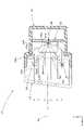
図1は、本願発明の一実施形態に係る車両用灯具10を示す正面図である。また、図2は、図1のII-II線断面図である。 FIG. 1 is a front view showing a
これらの図において、Xで示す方向が「灯具前方」(車両としては「後方」)であり、Yで示す方向が「灯具前方」と直交する「右方向」(車両としても「右方向」)であり、Zで示す方向が「上方向」である。なお、図1、2以外の図においても同様である。 In these drawings, the direction indicated by X is the "front of the lamp" ("rear" in terms of the vehicle), and the direction indicated by Y is the "right direction" orthogonal to the "front of the lamp" (also the "right direction" in the case of the vehicle). , and the direction indicated by Z is the "upward direction". The same applies to figures other than FIGS. 1 and 2. FIG.
図1、2に示すように、本実施形態に係る車両用灯具10は、車両後部に配置されるハイマウントストップランプであって、ランプボディ12とその前端開口部に取り付けられた素通し状の透光カバー14とで形成される灯室内に、複数の(具体的には12個の)発光素子20と透光部材30とが組み込まれた構成となっている。 As shown in FIGS. 1 and 2, a
複数の発光素子20は、その発光面20aを灯具前方(具体的には灯具正面方向)へ向けた状態で左右方向に互いに間隔をおいて(具体的には等間隔をおいて)配置されている。各発光素子20は赤色発光ダイオードであって、その発光面20aは矩形状(具体的には1×1mm程度の正方形)の外形形状を有している。 The plurality of light-emitting
複数の発光素子20は共通の基板22に搭載されており、この基板22はランプボディ12に支持されている。 A plurality of
透光部材30は、灯具正面視において横長矩形状の外形形状を有しており、複数の発光素子20の灯具前方側に配置されている。この透光部材30は、複数の発光素子20の各々からの出射光を透過制御するための複数の(具体的には12個の)透過制御部40が左右方向に並んだ状態で配置された構成となっている。各透過制御部40は、灯具正面視において同一サイズの矩形状(具体的には10×10mm程度の正方形)の外形形状を有している。 The
透光部材30は、無色透明の合成樹脂製(例えばアクリル樹脂製)の射出成形品として構成されている。この透光部材30には、複数の透過制御部40の周囲に平板状の外周フランジ部30aが形成されており、この外周フランジ部30aにおいてランプボディ12に支持されている。 The
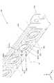
図3は、透光部材30の一部分を発光素子20と共に示す、図1のIII部詳細図である。また、図4は透光部材30の一部分を示す背面図であり、図5は図3のV-V線断面図である。さらに、図6は透光部材30の一部分を斜め前方から見て示す斜視図であり、図7は透光部材30の一部分を斜め後方から見て示す斜視図である。 FIG. 3 is a detailed view of part III of FIG. 4 is a rear view showing part of the
図3~7にも示すように、各透過制御部40は、灯具前後方向に延びる光軸Axを有している。そして各発光素子20は、その発光面20aの中心が各透過制御部40の光軸Ax上に位置するようにした状態で配置されている。 As also shown in FIGS. 3 to 7, each
各透過制御部40は、各発光素子20の灯具前方に位置する中心領域42と、この中心領域42の周囲に位置する周辺領域44とを備えている。 Each
中心領域42は、発光素子20からの出射光を偏向制御するレンズ部として構成されている。 The
具体的には、中心領域42は、前面42aが略凸曲面状に形成されるとともに後面42bが平面状に形成されており、灯具正面視において光軸Axを中心とする円形の外形形状を有している。その際、中心領域42の前面42aは、光軸Axを中心とする単一の凸曲面部42a1と、この凸曲面部42a1を囲む環状凸曲面部42a2とが同心円状に形成された構成となっている。 Specifically, the
環状凸曲面部42a2には、複数の拡散レンズ素子42a2sが形成されている。これら複数の拡散レンズ素子42a2sは、光軸Axを中心にして放射状に延びる境界線によって複数の扇形形状に区分けされたセグメントの各々に割り付けられており、いずれも魚眼レンズ状に形成されている。 A plurality of diffusion lens elements 42a2s are formed on the annular convex curved surface portion 42a2. These plurality of diffusing lens elements 42a2s are assigned to each of a plurality of sector-shaped segments divided by boundary lines radially extending around the optical axis Ax, and all of them are formed in the shape of a fisheye lens.
一方、周辺領域44は、発光素子20からの出射光を入射させる入射面44Aと、この入射面44Aから入射した光を灯具前方へ向けて全反射させる全反射面44Bと、この全反射面44Bで全反射した光を灯具前方へ向けて出射させる出射面44Cとを備えている。 On the other hand, the
入射面44Aおよび全反射面44Bは、中心領域42の後面42bから灯具後方側に突出するようにして形成されている。 The incident surface 44A and the
入射面44Aは、光軸Axを中心とする単一の環状面で構成されている。具体的には、この入射面44Aは、光軸Axを中心にして灯具後方側へ拡がる円錐面に略沿った環状面で構成されている。 The
全反射面44Bは、光軸Axに関して左右方向の両側に位置する1対の第1反射部44B1と、光軸Axに関して上下方向の両側に位置する1対の第2反射部44B2と、これら第1および第2反射部44B1、44B2の間に位置する4箇所の第3反射部44B3とを備えている。 The
各第1~第3反射部44B1~44B3は、入射面44Aから入射した発光素子20からの出射光を光軸Axと略平行な光として全反射させるようにその反射面形状が設定されている。 Each of the first to third reflecting portions 44B1 to 44B3 has a reflecting surface shape set so as to totally reflect the emitted light from the
その際、第2反射部44B2は、第1反射部44B1に対して外周側に変位した状態で(すなわち光軸Axからより遠い位置に)配置されており、その後端縁44B2aは第1反射部44B1の後端縁44B1aよりも灯具後方側に位置している。 At that time, the second reflecting portion 44B2 is arranged in a state of being displaced to the outer peripheral side with respect to the first reflecting portion 44B1 (that is, at a position farther from the optical axis Ax), and the rear edge 44B2a It is located on the rear side of the lamp from the rear edge 44B1a of 44B1.
また第3反射部44B3は、第2反射部44B2に対して外周側に変位した状態で配置されており、その後端縁44B3aは第2反射部44B2の後端縁44B2aよりも灯具後方側に位置している。 Further, the third reflecting portion 44B3 is arranged in a state of being displaced to the outer peripheral side with respect to the second reflecting portion 44B2, and the rear edge 44B3a is located on the rear side of the lamp from the rear edge 44B2a of the second reflecting portion 44B2. is doing.
なお全反射面44Bは、その上下両端部が水平面に沿ってカットされているので、第3反射部44B3が第2反射部44B2に対して外周側に変位しているにもかかわらず、第2および第3反射部44B2、44B3の上端縁は同一水平面上に位置している。 Since the
第1および第2反射部44B1、44B2の後端縁44B1a、44B2aは、入射面44Aと滑らかに繋がる凸曲線状の断面形状で、光軸Axを中心にして周方向に円弧状に延びるように形成されている。一方、第3反射部44B3の後端縁44B3aは、光軸Axと直交する鉛直面に沿って周方向に平面状に延びるように形成されている。 The rear edges 44B1a and 44B2a of the first and second reflecting portions 44B1 and 44B2 have a convex curved cross-sectional shape that smoothly connects to the
第3反射部44B3には、その後端縁44B3aにおける第1反射部44B1側の端部に面取りが施されており、これにより面取り部44B3bが形成されている。 The rear edge 44B3a of the third reflecting portion 44B3 is chamfered at the end on the first reflecting portion 44B1 side to form a chamfered portion 44B3b.
出射面44Cは、中心領域42の前面42aよりも灯具前方側の位置において光軸Axと直交する鉛直面上に複数の拡散レンズ素子44Csが形成された構成となっている。 The
複数の拡散レンズ素子44Csは、光軸Axを中心にして放射状および同心円状に延びる境界線によって複数の扇形形状に区分けされたセグメントの各々に割り付けられており、いずれも魚眼レンズ状に形成されている。 A plurality of diffusing lens elements 44Cs are assigned to each of a plurality of segments divided into a plurality of fan-shaped segments by boundary lines extending radially and concentrically around the optical axis Ax. .
図2、3、7に示すように、透光部材30における外周フランジ部30aの左右両端部には、灯具後方へ向けて延びる1対の鉛直リブ30bが形成されている。また、図2、4、7に示すように、複数の透過制御部40のうちいくつかの透過制御部40における周辺領域44には、上下1対の突起部30cが形成されている。 As shown in FIGS. 2, 3 and 7, a pair of
透光部材30は、ランプボディ12に支持される際、その外周フランジ部30aが灯具前方側からランプボディ12に押し当てられた状態で、左右1対の鉛直リブ30bおよび上下複数対の突起部30cにおいてランプボディ12の内周面と係合するように構成されており、これによりランプボディ12に対する位置決めが確実に行われるようになっている。 When the
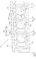
図8は、車両用灯具10を点灯状態で示す正面図である。 FIG. 8 is a front view showing the
図8に示すように、複数の発光素子20が同時に点灯すると、透光部材30を構成する複数の透過制御部40の各々が光って見える。 As shown in FIG. 8, when the plurality of
その際、各透過制御部40は、中心領域42のみならず周辺領域44もその全域にわたって光って見え、全体として略矩形状の輪郭で光って見える。これは、第3反射部44B3が第1および第2反射部44B1、44B2に対して外周側に変位した状態で配置されていることによるものである。 At that time, each
しかも、各透過制御部40は、その全周にわたって外周縁部まで明るく光って見える。これは、周辺領域44の入射面44Aが単一の環状面で構成されており、これにより各発光素子20からの出射光が入射面44Aから効率良く入射して第1、第2および第3反射部44B3の各々に到達することによるものである。 In addition, each
なお、各透過制御部40の中心領域42は、凸曲面部42a1が円形状に光って見えるとともに環状凸曲面部42a2が各拡散レンズ素子42a2s毎に光って見える。また、各透過制御部40の周辺領域44は、各拡散レンズ素子42a2sが散点的に光って見える。 In the
次に、本実施形態の作用効果について説明する。 Next, the effects of this embodiment will be described.
本実施形態に係る車両用灯具10は、発光面20aを灯具前方へ向けて配置された複数の発光素子20を備えており、その出射光を透光部材30における複数の透過制御部40によって透過制御する構成となっているが、各透過制御部40は、各発光素子20の灯具前方に位置する中心領域42とその周囲に位置する周辺領域44とを備えており、かつ、周辺領域44は発光素子20からの出射光を入射させる入射面44Aとその入射光を灯具前方へ向けて全反射させる全反射面44Bとその全反射光を灯具前方へ向けて出射させる出射面44Cとを備えているので、発光素子20が点灯したとき中心領域42のみならず周辺領域44も光って見えるようにすることができる。 A
その際、各透過制御部40における周辺領域44の全反射面44Bは、左右方向(灯具前後方向と交差する第1の方向)に位置する1対の第1反射部44B1と、上下方向(第1の方向と直交する第2の方向)に位置する1対の第2反射部44B2と、これらの間に位置する4箇所の第3反射部44B3とを備えており、かつ、第3反射部44B3は第1および第2反射部44B1、44B2に対して外周側に変位した状態で配置されているので、複数の発光素子20が点灯したとき複数の透過制御部40の各々の周辺領域44がその全域にわたって光って見えるようにすることができる。 At that time, the
その上で、各透過制御部40の周辺領域44は、その入射面44Aが単一の環状面で構成されているので、発光素子20からの出射光を入射面44Aから効率良く入射させて第1、第2および第3反射部44B1、44B2、44B3の各々に到達させることができる。したがって透光部材30として、複数の透過制御部40の各々がその全周にわたって外周縁部まで明るく光って見えるようにすることができる。 In addition, since the
このように本実施形態によれば、複数の発光素子20からの出射光を透光部材30によって透過制御するように構成された車両用灯具10において、透光部材30を構成する複数の透過制御部40の各々がその全周にわたって外周縁部まで明るく光って見えるようにすることができる。 As described above, according to the present embodiment, in the
しかも本実施形態においては、各透過制御部40の周辺領域44における全反射面44Bの構成として、第3反射部44B3の後端縁44B3aが第1および第2反射部44B1、44B2の後端縁44B1a、44B2aよりも灯具後方側に位置するように形成されているので、次のような作用効果を得ることができる。 Moreover, in this embodiment, as the configuration of the
すなわち、第3反射部44B3が第1および第2反射部44B1、44B2に対して外周側に変位した状態で配置されているにもかかわらず、第3反射部44B3での反射光量を第1および第2反射部44B1、44B2の各々での反射光量に近づけることができ、これにより各透過制御部40の周辺領域44の明るさの均一性を向上させることができる。 That is, even though the third reflecting portion 44B3 is displaced to the outer peripheral side with respect to the first and second reflecting portions 44B1 and 44B2, the amount of light reflected by the third reflecting portion 44B3 is The amount of light reflected by each of the second reflection portions 44B1 and 44B2 can be approximated, thereby improving the uniformity of the brightness of the
さらに本実施形態においては、第2反射部44B2が第1反射部44B1に対して外周側に変位した状態で配置されており、これに伴い第2反射部44B2の後端縁44B2aは第2反射部44B1の後端縁44B1aよりも灯具後方側に位置するように形成されているので、発光素子20からの出射光のうち、上下方向に関して周辺領域44の入射面44Aから外れた方向へ向かう光を少なくすることができる。そしてこれにより、各透過制御部40からの漏光が不用意に発生してしまうのを効果的に抑制することができる。 Furthermore, in the present embodiment, the second reflecting portion 44B2 is arranged in a state of being displaced to the outer peripheral side with respect to the first reflecting portion 44B1. Since the rear end edge 44B1a of the portion 44B1 is formed so as to be located on the rear side of the lamp, among the emitted light from the
また本実施形態においては、第3反射部44B3の後端縁44B3aに面取りが施されているので、透光部材30の成形するための金型構造を成立させることが容易に可能となる。その際、この面取りによって形成された面取り部44B3bは、第3反射部44B3の後端縁44B3aにおける第1反射部44B1側の端部(すなわち、第1および第3反射部44B1、44B3の後端縁44B1a、44B3a相互間に大きな段差が生じている部分)に位置しているので、金型構造の容易化を効果的に高めることができる。 Further, in this embodiment, since the rear edge 44B3a of the third reflecting portion 44B3 is chamfered, a mold structure for molding the
上記実施形態においては、各透過制御部40の周辺領域44の構成として、入射面44Aから入射した発光素子20からの出射光を全反射面44Bにおいて光軸Axと略平行な光として灯具前方へ向けて全反射させる構成となっているものとして説明したが、光軸Axと略平行な光ではない光(例えば径方向や周方向に多少拡散する光)として灯具前方へ向けて全反射させる構成とすることも可能である。 In the above-described embodiment, as the configuration of the
上記実施形態においては、各透過制御部40の周辺領域44における入射面44Aが、光軸Axを中心にして灯具後方側へ拡がる円錐面に略沿った環状面で構成されているものとして説明したが、これ以外の環状面(例えば、楕円環面や矩形環面等に略沿った環状面)で構成することも可能である。 In the above embodiment, the
上記実施形態においては、各透過制御部40の周辺領域44における出射面44Cを構成する複数の拡散レンズ素子44Csが、光軸Axを中心にして放射状および同心円状に配置されているものとして説明したが、これ以外の配置(例えば縦横格子状の配置等)を採用することも可能である。 In the above embodiment, the plurality of diffuser lens elements 44Cs forming the
上記実施形態においては、透光部材30が灯具正面視において横長矩形状の外形形状を有しているものとして説明したが、これ以外の外形形状(例えば、縦長矩形状や円弧状あるいは円環状に細長く延びる外形形状等)を有する構成とすることも可能である。 In the above embodiment, the
上記実施形態においては、車両用灯具10の構成として、ランプボディ12と透光カバー14とで形成される灯室内に複数の発光素子20と透光部材30とが組み込まれているものとして説明したが、車室内後部に配置されるハイマウントストップランプ等の場合には透光カバー14が存在しない構成することも可能である。 In the above-described embodiment, the configuration of the
上記実施形態においては、車両用灯具10が車両後部に配置されるハイマウントストップランプである場合について説明したが、車両に設けられる箇所や機能にかかわらず、上記実施形態と同様の構成を採用することにより上記実施形態と同様の作用効果を得ることができる。すなわち、ハイマウントストップランプ以外にも、例えば、テール&ストップランプ、リアフォグランプ、デイタイムランニングランプ、クリアランスランプ等が採用可能である。その際、各灯具の機能に合わせて複数の発光素子120として赤色の発光ダイオードの他にも白色やアンバ色の発光ダイオードを使用することが可能である。 In the above embodiment, the case where the
次に、上記実施形態の変形例について説明する。 Next, a modification of the above embodiment will be described.
まず、上記実施形態の第1変形例について説明する。 First, a first modified example of the above embodiment will be described.
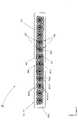
図9は、本変形例に係る車両用灯具110を示す、図8と同様の図である。 FIG. 9 is a view similar to FIG. 8 showing a
図9に示すように、本変形例に係る車両用灯具110も、その基本的な構成は上記実施形態の場合と同様であるが、複数の発光素子120の種類および点灯の仕方が上記実施形態の場合と異なっている。 As shown in FIG. 9, the
すなわち、本変形例に係る車両用灯具110は、ウェルカムランプ(すなわち駐車中の車両に対してドライバーが近づいたり離れたりする際に点灯する灯具)であって、複数の発光素子120としてターコイズ色(すなわち青緑色)に発光する発光ダイオードが用いられている。 That is, the
また、本変形例に係る車両用灯具110は、複数の発光素子120が同時点灯するだけでなく、一部の発光素子140が順次点灯し得る構成となっている。 In addition, the
図9においては、12個の発光素子120のうち6個の発光素子120が順次点灯する様子を示している。 FIG. 9 shows how six
すなわち、まず右半分(灯具正面視では左半分)の6個の発光素子120が点灯し(図9(a)参照)、次に右から3番目から8番目までの6個の発光素子120が点灯し(図9(b)参照)、次に右から5番目から10番目までの6個の発光素子120が点灯し(図9(c)参照)、最後に左半分の6個の発光素子120が点灯する(図9(d)参照)様子を示している。 That is, first, the right half (the left half when the lamp is viewed from the front) of the six
本変形例に係る車両用灯具110のように、複数の発光素子120が順次点灯し得る構成とすることにより、ウェルカムランプとしての機能を高めることができる。 As in the
なお、図9に示すように6個の発光素子120が順次点灯する態様以外にも、発光素子120の点灯個数が徐々に増えるように変化する態様や、発光素子120の点灯個数がランダムに変化する態様等を採用することも可能である。 In addition to the mode in which the six
本変形例に係る車両用灯具110を、車両が自動運転状態にあることを表示するための自動運転用ランプとして用いることも可能である。 The
また、本変形例に係る車両用灯具110を、電気自動車に対してインジケータランプとして搭載し、複数の発光素子120の点灯個数によってバッテリーの充電状態の表示を行う構成を採用することも可能である。 Further, it is also possible to adopt a configuration in which the
さらに、上記実施形態に係る車両用灯具10に関しても、複数の発光素子20の点灯個数を制御し得る構成を採用することにより、ハイマウントストップランプとインジケータランプ等との兼用を図ることも可能である。 Further, the
次に、上記実施形態の第2変形例について説明する。 Next, the 2nd modification of the said embodiment is demonstrated.
図10(a)は、本変形例に係る透光部材230を示す、図5と略同様の図である。 FIG. 10(a) is a view substantially similar to FIG. 5, showing a
図10(a)に示すように、本変形例に係る透光部材230も、その基本的な構成は上記実施形態の場合と同様であるが、各透過制御部240の周辺領域244における全反射面244Bの構成が上記実施形態の場合と一部異なっている。 As shown in FIG. 10A, the
すなわち本変形例においては、全反射面244Bを構成する第1、第2および第3反射部44B1、244B2、44B3のうち、第2反射部244B2の構成が上記実施形態の場合と一部異なっている。 That is, in this modified example, among the first, second, and third reflecting portions 44B1, 244B2, and 44B3 constituting the
具体的には、本変形例の第2反射部244B2は、光軸Axに関して第1反射部44B1と同一曲面上に位置するように形成されている。これに伴い、第2反射部244B2の後端縁244B2aは第1反射部44B1の後端縁44B1aと同一鉛直面上に位置するように形成されている。 Specifically, the second reflecting portion 244B2 of this modified example is formed so as to be positioned on the same curved surface as the first reflecting portion 44B1 with respect to the optical axis Ax. Along with this, the rear edge 244B2a of the second reflector 244B2 is formed so as to be positioned on the same vertical plane as the rear edge 44B1a of the first reflector 44B1.
本変形例の構成を採用することにより、入射面44Aから入射した発光素子20からの出射光の反射光量を、第1、第2および第3反射部44B1、244B2、44B3相互間において略均等にすることが容易に可能となり、これにより複数の透過制御部40の各々の周辺領域44がその全域にわたって略均等に光って見えるようにすることが容易に可能となる。 By adopting the configuration of this modified example, the amount of reflected light of the emitted light from the
次に、上記実施形態の第3変形例について説明する。 Next, the 3rd modification of the said embodiment is demonstrated.
図10(b)は、本変形例に係る透光部材330を示す、図5と略同様の図である。 FIG. 10(b) is a view substantially similar to FIG. 5, showing a
図10(b)に示すように、本変形例に係る透光部材330も、その基本的な構成は上記実施形態の場合と同様であるが、各透過制御部340の周辺領域344における全反射面344Bの構成が上記実施形態の場合と一部異なっている。 As shown in FIG. 10B, the
すなわち本変形例においては、全反射面344Bを構成する第1、第2および第3反射部44B1、344B2、44B3のうち、第2反射部344B2の構成が上記実施形態の場合と一部異なっている。 That is, in this modified example, among the first, second, and third reflecting portions 44B1, 344B2, and 44B3 constituting the
具体的には、本変形例の第2反射部344B2は、その後端縁344B2aが第3反射部44B3の後端縁44B3aと同一鉛直面上に位置するように形成されている。ただし、第3反射部44B3は、その後端縁44B3aが径方向に一定の幅を有する平面部として形成されているので、第3反射部44B3が第2反射部344B2に対して外周側に変位した状態で配置されている状態は、本変形例においても維持されている。 Specifically, the second reflecting portion 344B2 of this modified example is formed such that the rear edge 344B2a is positioned on the same vertical plane as the rear edge 44B3a of the third reflecting portion 44B3. However, since the rear edge 44B3a of the third reflecting portion 44B3 is formed as a planar portion having a constant width in the radial direction, the third reflecting portion 44B3 is displaced to the outer peripheral side with respect to the second reflecting portion 344B2. The state of being arranged in the state is also maintained in this modified example.
本変形例の構成を採用することにより、発光素子20から出射した後、第2反射部344B2の後端縁344B2aよりも灯具後方側の空間を通って透過制御部340の上下に位置する空間に漏れ出してしまう光を最小限に抑えることができる。そしてこれにより、各透過制御部340からの漏光が不用意に発生してしまうのを一層効果的に抑制することができる。 By adopting the configuration of this modified example, after the light is emitted from the
次に、上記実施形態の第4変形例について説明する。 Next, the 4th modification of the said embodiment is demonstrated.
図11(a)は、本変形例に係る透光部材430を示す、図6と略同様の図であり、図11(b)は、図11(a)のb-b線断面図である。 FIG. 11(a) is a diagram substantially similar to FIG. 6, showing a
図11(a)、(b)に示すように、本変形例に係る透光部材430も、その基本的な構成は上記実施形態の場合と同様であるが、各透過制御部440の周辺領域444における出射面444Cの構成が上記実施形態の場合と一部異なっている。 As shown in FIGS. 11A and 11B, the
すなわち本変形例においては、出射面444Cを構成する複数の拡散レンズ素子44Csのうち、一部の拡散レンズ素子444Csが他の拡散レンズ素子44Csに対して灯具後方側に変位した状態で配置されている。 That is, in this modified example, some of the diffuser lens elements 44Cs among the plurality of diffuser lens elements 44Cs forming the
具体的には、出射面444Cにおいて、4箇所の第3反射部44B3の灯具前方に位置する4箇所の拡散レンズ素子444Csが他の拡散レンズ素子44Csに対して灯具後方側に変位した状態で配置されている。なお、拡散レンズ素子444Csの表面形状については他の拡散レンズ素子44Csの表面形状と同様である。 Specifically, on the
本変形例の構成を採用することにより、透光部材430として各透過制御部440の周辺領域44の肉厚の均一化を図ることが可能となる。そしてこれにより、透光部材430を射出成形によって製造する際の成形性を高めることができる。 By adopting the configuration of this modified example, it is possible to make the thickness of the
なお、上記実施形態およびその変形例において諸元として示した数値は一例にすぎず、これらを適宜異なる値に設定してもよいことはもちろんである。 It should be noted that the numerical values shown as specifications in the above-described embodiment and its modification are merely examples, and it goes without saying that these values may be set to different values as appropriate.
また、本願発明は、上記実施形態およびその変形例に記載された構成に限定されるものではなく、これ以外の種々の変更を加えた構成が採用可能である。 Moreover, the present invention is not limited to the configurations described in the above embodiments and modifications thereof, and configurations with various other modifications can be adopted.
10、110 車両用灯具
12 ランプボディ
14 透光カバー
20、120 発光素子
20a 発光面
22 基板
30、230、330、430 透光部材
30a 外周フランジ部
30b 鉛直リブ
30c 突起部
40、240、340、440 透過制御部
42 中心領域
42a 前面
42a1 凸曲面部
42a2 環状凸曲面部
42a2s 拡散レンズ素子
42b 後面
44、244、344、444 周辺領域
44A 入射面
44B、244B、344B 全反射面
44B1 第1反射部
44B1a、44B2a、44B3a、244B2a、344B2a 後端縁
44B2、244B2、344B2 第2反射部
44B3 第3反射部
44B3b 面取り部
44C、444C 出射面
44Cs、444Cs 拡散レンズ素子
Ax 光軸
Claims (5)
Translated fromJapanese上記複数の発光素子は、発光面を灯具前方へ向けた状態で灯具前後方向と交差する第1の方向に互いに間隔をおいて配置されており、
上記透光部材は、上記複数の発光素子の各々からの出射光を透過制御するための複数の透過制御部を備えており、
上記複数の透過制御部は、上記第1の方向に並んだ状態で配置されており、
上記各透過制御部は、上記各発光素子の灯具前方に位置する中心領域と、上記中心領域の周囲に位置する周辺領域とを備えており、
上記中心領域は、上記発光素子からの出射光を偏向制御するレンズ部として構成されており、
上記周辺領域は、上記発光素子からの出射光を入射させる入射面と、上記入射面から入射した光を灯具前方へ向けて全反射させる全反射面と、上記全反射面で全反射した光を灯具前方へ向けて出射させる出射面とを備えており、
上記全反射面は、上記第1の方向に位置する第1反射部と、上記第1の方向と直交する第2の方向に位置する第2反射部と、上記第1および第2反射部の間に位置する第3反射部とを備えており、
上記第3反射部は、上記第1および第2反射部に対して外周側に変位した状態で配置されており、
上記入射面は単一の環状面で構成されている、ことを特徴とする車両用灯具。A vehicle lamp comprising a plurality of light emitting elements and a translucent member arranged in front of the plurality of light emitting elements,
The plurality of light-emitting elements are arranged at intervals in a first direction intersecting the front-rear direction of the lamp with the light-emitting surfaces facing forward of the lamp, and
The translucent member includes a plurality of transmission control units for controlling transmission of light emitted from each of the plurality of light emitting elements,
The plurality of transmission control units are arranged in a row in the first direction,
each of the transmission control units includes a central region positioned in front of the lamp of each light emitting element and a peripheral region positioned around the central region,
The central region is configured as a lens portion that controls the deflection of light emitted from the light emitting element,
The peripheral area includes an incident surface for incident light emitted from the light emitting element, a total reflection surface for totally reflecting the light incident from the incident surface toward the front of the lamp, and the light totally reflected by the total reflection surface. and an emission surface for emitting light toward the front of the lamp,
The total reflection surface includes a first reflecting portion positioned in the first direction, a second reflecting portion positioned in a second direction orthogonal to the first direction, and the first and second reflecting portions. and a third reflecting portion positioned between,
The third reflecting portion is arranged in a state of being displaced to the outer peripheral side with respect to the first and second reflecting portions,
The vehicular lamp, wherein the incident surface is composed of a single annular surface.
Priority Applications (2)
| Application Number | Priority Date | Filing Date | Title |
|---|---|---|---|
| JP2021051614AJP7535000B2 (en) | 2021-03-25 | 2021-03-25 | Vehicle lighting fixtures |
| CN202210229950.6ACN115127074B (en) | 2021-03-25 | 2022-03-10 | Lamp for vehicle |
Applications Claiming Priority (1)
| Application Number | Priority Date | Filing Date | Title |
|---|---|---|---|
| JP2021051614AJP7535000B2 (en) | 2021-03-25 | 2021-03-25 | Vehicle lighting fixtures |
Publications (2)
| Publication Number | Publication Date |
|---|---|
| JP2022149446Atrue JP2022149446A (en) | 2022-10-06 |
| JP7535000B2 JP7535000B2 (en) | 2024-08-15 |
Family
ID=83376029
Family Applications (1)
| Application Number | Title | Priority Date | Filing Date |
|---|---|---|---|
| JP2021051614AActiveJP7535000B2 (en) | 2021-03-25 | 2021-03-25 | Vehicle lighting fixtures |
Country Status (2)
| Country | Link |
|---|---|
| JP (1) | JP7535000B2 (en) |
| CN (1) | CN115127074B (en) |
Citations (4)
| Publication number | Priority date | Publication date | Assignee | Title |
|---|---|---|---|---|
| US20190170990A1 (en)* | 2017-12-06 | 2019-06-06 | Varroc Lighting Systems, s.r.o. | Collimator, especially for the light device of a vehicle, and an optical module comprising the collimator |
| JP2019165021A (en)* | 2019-07-03 | 2019-09-26 | 株式会社小糸製作所 | Vehicular lighting fixture |
| CN211293468U (en)* | 2019-05-14 | 2020-08-18 | 法雷奥照明湖北技术中心有限公司 | Optical structure, corresponding vehicle lamp and vehicle |
| JP2020170586A (en)* | 2019-04-01 | 2020-10-15 | 株式会社小糸製作所 | Lighting fixture for vehicle |
Family Cites Families (9)
| Publication number | Priority date | Publication date | Assignee | Title |
|---|---|---|---|---|
| JP2008059901A (en)* | 2006-08-31 | 2008-03-13 | Koito Mfg Co Ltd | Marker lamp for vehicle |
| JP4964753B2 (en)* | 2007-12-12 | 2012-07-04 | 株式会社小糸製作所 | Lighting fixtures for vehicles |
| US9340147B2 (en)* | 2011-11-29 | 2016-05-17 | Koito Manufacturing Co., Ltd. | Vehicle lamp |
| EP3179158A4 (en)* | 2014-08-07 | 2018-03-21 | Koito Manufacturing Co., Ltd. | Lamp for vehicles |
| JP6597024B2 (en)* | 2015-07-29 | 2019-10-30 | 市光工業株式会社 | Vehicle lighting |
| CN108474532B (en)* | 2015-12-15 | 2020-11-10 | 株式会社小糸制作所 | Vehicle lamp and substrate |
| US10330282B2 (en)* | 2017-09-05 | 2019-06-25 | T.Y.C. Brother Industrial Co., Ltd. | Vehicle lamp lens |
| JP2019125532A (en)* | 2018-01-18 | 2019-07-25 | 株式会社小糸製作所 | Lighting fixture |
| JP7291584B2 (en)* | 2019-09-17 | 2023-06-15 | 株式会社小糸製作所 | vehicle lamp |
- 2021
- 2021-03-25JPJP2021051614Apatent/JP7535000B2/enactiveActive
- 2022
- 2022-03-10CNCN202210229950.6Apatent/CN115127074B/enactiveActive
Patent Citations (4)
| Publication number | Priority date | Publication date | Assignee | Title |
|---|---|---|---|---|
| US20190170990A1 (en)* | 2017-12-06 | 2019-06-06 | Varroc Lighting Systems, s.r.o. | Collimator, especially for the light device of a vehicle, and an optical module comprising the collimator |
| JP2020170586A (en)* | 2019-04-01 | 2020-10-15 | 株式会社小糸製作所 | Lighting fixture for vehicle |
| CN211293468U (en)* | 2019-05-14 | 2020-08-18 | 法雷奥照明湖北技术中心有限公司 | Optical structure, corresponding vehicle lamp and vehicle |
| JP2019165021A (en)* | 2019-07-03 | 2019-09-26 | 株式会社小糸製作所 | Vehicular lighting fixture |
Also Published As
| Publication number | Publication date |
|---|---|
| CN115127074B (en) | 2024-05-03 |
| CN115127074A (en) | 2022-09-30 |
| JP7535000B2 (en) | 2024-08-15 |
Similar Documents
| Publication | Publication Date | Title |
|---|---|---|
| JP6194040B2 (en) | Vehicle lighting | |
| JP4094366B2 (en) | Vehicle lighting | |
| JP6203519B2 (en) | Vehicle lighting | |
| US8591083B2 (en) | Vehicular lamp | |
| JP6381113B2 (en) | Vehicle lighting | |
| US20140056016A1 (en) | Automotive Lighting Unit | |
| JP4290607B2 (en) | Vehicle lighting | |
| JP7019403B2 (en) | Vehicle lighting | |
| JP2014089941A (en) | Vehicular lighting unit | |
| JP2014038733A (en) | Lamp for vehicle | |
| JP7176961B2 (en) | rear combination lamp | |
| JP7402119B2 (en) | Vehicle lights | |
| JP2013122872A (en) | Illumination lamp fitting for vehicle | |
| CN203010497U (en) | Integrated Radial Lamp Lens | |
| JP7478030B2 (en) | Vehicle lighting fixtures | |
| JP2016225044A (en) | Vehicle lighting | |
| JP2022069185A (en) | Vehicular lighting | |
| JP2022149446A (en) | Vehicle lighting appliance | |
| KR20180039945A (en) | Lamp for vehicle | |
| JP2014107223A (en) | Vehicular lighting fixture | |
| CN220366317U (en) | Light guide element, lighting and/or signalling device and vehicle | |
| JP7458895B2 (en) | Vehicle lights | |
| JP5937339B2 (en) | Vehicle signal lights | |
| JP2023167863A (en) | Vehicular lighting fixture | |
| WO2024127975A1 (en) | Vehicle lamp |
Legal Events
| Date | Code | Title | Description |
|---|---|---|---|
| A621 | Written request for application examination | Free format text:JAPANESE INTERMEDIATE CODE: A621 Effective date:20240119 | |
| A977 | Report on retrieval | Free format text:JAPANESE INTERMEDIATE CODE: A971007 Effective date:20240619 | |
| A131 | Notification of reasons for refusal | Free format text:JAPANESE INTERMEDIATE CODE: A131 Effective date:20240626 | |
| A521 | Request for written amendment filed | Free format text:JAPANESE INTERMEDIATE CODE: A523 Effective date:20240712 | |
| TRDD | Decision of grant or rejection written | ||
| A01 | Written decision to grant a patent or to grant a registration (utility model) | Free format text:JAPANESE INTERMEDIATE CODE: A01 Effective date:20240731 | |
| A61 | First payment of annual fees (during grant procedure) | Free format text:JAPANESE INTERMEDIATE CODE: A61 Effective date:20240802 | |
| R150 | Certificate of patent or registration of utility model | Ref document number:7535000 Country of ref document:JP Free format text:JAPANESE INTERMEDIATE CODE: R150 |