Movatterモバイル変換


[0]ホーム

URL:


JP2022149407A - Electronic device - Google Patents

Electronic device
Download PDF

Info

Publication number
JP2022149407A
JP2022149407AJP2021051547AJP2021051547AJP2022149407AJP 2022149407 AJP2022149407 AJP 2022149407AJP 2021051547 AJP2021051547 AJP 2021051547AJP 2021051547 AJP2021051547 AJP 2021051547AJP 2022149407 AJP2022149407 AJP 2022149407A
Authority
JP
Japan
Prior art keywords
exterior
microphone
hole
engaging
convex
Prior art date
Legal status (The legal status is an assumption and is not a legal conclusion. Google has not performed a legal analysis and makes no representation as to the accuracy of the status listed.)
Granted
Application number
JP2021051547A
Other languages
Japanese (ja)
Other versions
JP7188485B2 (en
Inventor
富男 肥後
Tomio Higo
Current Assignee (The listed assignees may be inaccurate. Google has not performed a legal analysis and makes no representation or warranty as to the accuracy of the list.)
Casio Computer Co Ltd
Original Assignee
Casio Computer Co Ltd
Priority date (The priority date is an assumption and is not a legal conclusion. Google has not performed a legal analysis and makes no representation as to the accuracy of the date listed.)
Filing date
Publication date
Application filed by Casio Computer Co LtdfiledCriticalCasio Computer Co Ltd
Priority to JP2021051547ApriorityCriticalpatent/JP7188485B2/en
Publication of JP2022149407ApublicationCriticalpatent/JP2022149407A/en
Application grantedgrantedCritical
Publication of JP7188485B2publicationCriticalpatent/JP7188485B2/en
Activelegal-statusCriticalCurrent
Anticipated expirationlegal-statusCritical

Links

Images

Landscapes

Abstract

To restrain noise such as rubbing noise from being inputted into a microphone in an electronic device comprising an exterior and the microphone.SOLUTION: A robot 200 comprises: an exterior 201; a body part 207 covered by the exterior 201; an engagement plate 260 provided inside the exterior 201; a convex component 242 provided in the body part 207, and for locking the exterior 201 on the body part 207 by engaging with the engagement plate 260; and a microphone 290. The convex component 242 comprises a through hole penetrating the convex component 242 in the height direction of the convex component 242. The microphone 290 is arranged at a position opposed to the through hole, inside the body part 207.SELECTED DRAWING: Figure 2

Description

Translated fromJapanese

本発明は、電子機器に関する。 The present invention relates to electronic equipment.

ペットのような親しみのあるロボットが知られている。例えば、特許文献1は、ペットとして飼育される動物に似せた外観形状を有するロボットを開示している。特許文献1には、ロボットに個性を持たせるために、ロボットにその本体部を覆う外装が装着されることが開示されている。また、特許文献1には、ロボットが耳に相当するマイクロホンを備えており、マイクロホンで集音したユーザからのサウンドコマンドに基づいて動作することが開示されている。 Robots that are familiar like pets are known. For example, Patent Literature 1 discloses a robot having an external shape that resembles an animal kept as a pet. Patent Literature 1 discloses that a robot is equipped with an exterior that covers its main body in order to give the robot individuality. Further, Patent Document 1 discloses that a robot is equipped with a microphone corresponding to an ear, and operates based on a sound command from a user collected by the microphone.

特開2001-191276号公報Japanese Patent Application Laid-Open No. 2001-191276

上記のような外装及びマイクロホンを備えるロボットにおいて、ロボットが動いた際に、外装がロボットの本体部に擦れることによる擦れ音が生じることがある。このような擦れ音が生じると、擦れ音をマイクロホンが拾い、外部からの何らかの意味のある音であるとロボットの処理装置が誤認識し、ロボットが誤反応してしまう、という課題がある。またマイクロホンから入力される音に反応するが、自身は動かない、外装を備える電子機器であっても、電子機器を持ち運び等する際に同様の課題が発生する。 In a robot equipped with an exterior and a microphone as described above, when the robot moves, the exterior rubs against the main body of the robot, which may cause a rubbing sound. When such a rubbing sound occurs, the microphone picks up the rubbing sound, and the processor of the robot mistakenly recognizes that it is some kind of meaningful sound from the outside, causing the robot to react erroneously. Even an electronic device with an exterior that responds to sound input from a microphone but does not move itself poses a similar problem when the electronic device is carried.

本発明は、上記のような問題点を解決するためになされたものであり、外装及びマイクロホンを備える電子機器において、擦れ音のようなノイズがマイクロホンに入力されることを抑えることが可能な電子機器を提供することを目的とする。 SUMMARY OF THE INVENTION The present invention has been made to solve the above problems, and is an electronic device that is capable of suppressing input of noise such as scraping noise to the microphone in an electronic device having an exterior and a microphone. The purpose is to provide equipment.

上記目的を達成するため、本発明に係る電子機器の第1の態様は、
外装と、
前記外装に覆われる本体部と、
前記外装の内側に設けられた係合部と、
前記本体部に設けられ、前記係合部と係合することにより前記外装を前記本体部に係止する被係合部と、
マイクロホンと、を備え、
前記係合部と前記被係合部とのうちの一方は、嵌合部を有し、
前記係合部と前記被係合部とのうちの他方は、前記嵌合部に嵌合する凸状部品であり、
前記凸状部品は、前記凸状部品の高さ方向に前記凸状部品を貫通する貫通孔を有し、
前記マイクロホンは、前記本体部の内部において前記貫通孔に対向する位置に配置されている。
In order to achieve the above object, a first aspect of an electronic device according to the present invention includes:
Exterior and
a main body covered with the exterior;
an engaging portion provided inside the exterior;
a to-be-engaged portion provided on the main body portion for locking the exterior to the main body portion by engaging with the engaging portion;
a microphone;
one of the engaging portion and the engaged portion has a fitting portion;
the other of the engaging portion and the engaged portion is a convex component that fits into the fitting portion;
The convex part has a through hole penetrating the convex part in the height direction of the convex part,
The microphone is arranged inside the main body at a position facing the through hole.

上記目的を達成するため、本発明に係る電子機器の第2の態様は、
外装と、
前記外装に覆われる本体部と、
前記外装の内側に設けられた係合部と、
前記本体部に設けられ、前記係合部と係合することにより前記外装を前記本体部に係止する被係合部と、
マイクロホンと、を備え、
前記係合部と前記被係合部とのうちの一方は、嵌合部を有し、
前記係合部と前記被係合部とのうちの他方は、前記嵌合部に嵌合する凸状部品であり、
前記凸状部品は、前記凸状部品の高さ方向に前記凸状部品を貫通する貫通孔を有し、
前記マイクロホンは、前記貫通孔の内部に配置されている。
In order to achieve the above object, a second aspect of the electronic device according to the present invention includes:
Exterior and
a main body covered with the exterior;
an engaging portion provided inside the exterior;
a to-be-engaged portion provided on the main body portion for locking the exterior to the main body portion by engaging with the engaging portion;
a microphone;
one of the engaging portion and the engaged portion has a fitting portion;
the other of the engaging portion and the engaged portion is a convex component that fits into the fitting portion;
The convex part has a through hole penetrating the convex part in the height direction of the convex part,
The microphone is arranged inside the through hole.

本発明によれば、外装及びマイクロホンを備える電子機器において、擦れ音のようなノイズがマイクロホンに入力されることを抑えることができる。 According to the present invention, in an electronic device having an exterior and a microphone, it is possible to suppress input of noise such as rubbing noise to the microphone.

実施の形態1に係るロボットの斜視図である。1 is a perspective view of a robot according to Embodiment 1; FIG.実施の形態1に係るロボットの断面図である。1 is a cross-sectional view of a robot according to Embodiment 1; FIG.実施の形態1に係るロボットの本体部を説明するための斜視図である。FIG. 2 is a perspective view for explaining the main body of the robot according to Embodiment 1;実施の形態1に係る凸状部品及び係合板の断面図を示す図であり、(a)は凸状部品が貫通孔を有しない場合の図、(b)は凸状部品が貫通孔を有する場合の図である。FIG. 2 is a diagram showing cross-sectional views of a convex component and an engaging plate according to Embodiment 1, where (a) is a diagram in which the convex component does not have a through hole, and (b) is a diagram in which the convex component has a through hole; FIG. 10 is a diagram of a case;実施の形態1に係る貫通孔を有しない凸状部品及び係合板を示す図であり、(a)は互いが係合していない状態の斜視図、(b)は互いが係合した状態の斜視図である。FIG. 4A is a perspective view of a protruding part having no through-hole and an engaging plate according to Embodiment 1, where (a) is a perspective view of a state in which they are not engaged with each other, and (b) is a view in which they are engaged with each other; It is a perspective view.実施の形態1に係る貫通孔を有する凸状部品及び係合板を示す図であり、(a)は互いが係合していない状態の斜視図、(b)は互いが係合した状態の斜視図である。FIG. 4A is a perspective view of a convex component having a through hole and an engagement plate according to Embodiment 1, where (a) is a perspective view of a state in which they are not engaged with each other, and (b) is a perspective view of a state in which they are engaged with each other; It is a diagram.実施の形態2に係る凸状部品及び係合板の断面図を示す図であり、(a)は凸状部品が貫通孔を有しない場合の図、(b)は凸状部品が貫通孔を有する場合の図である。FIG. 10 is a diagram showing cross-sectional views of a convex component and an engaging plate according to Embodiment 2, where (a) is a diagram in which the convex component does not have a through hole, and (b) is a diagram in which the convex component has a through hole; FIG. 10 is a diagram of a case;実施の形態3に係る貫通孔を有する凸状部品及び係合板の断面図を示す図である。FIG. 10 is a diagram showing a cross-sectional view of a convex component having through holes and an engaging plate according to Embodiment 3;実施の形態4に係る貫通孔を有する凸状部品及び係合板の断面図を示す図である。FIG. 11 is a diagram showing a cross-sectional view of a convex component having a through hole and an engagement plate according to Embodiment 4;

以下、本発明の実施の形態について、図面を参照しながら説明する。なお、実施の形態の理解を容易にするため、図1中の前後の方向を適宜参照しながら説明する。 BEST MODE FOR CARRYING OUT THE INVENTION Hereinafter, embodiments of the present invention will be described with reference to the drawings. In order to facilitate understanding of the embodiment, the description will be made with reference to the front and rear directions in FIG. 1 as appropriate.

(実施の形態1)
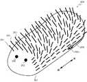
図1に、実施の形態1に係る電子機器であるロボット200の外観を示す。ロボット200は、小動物を模したペットロボットである。ロボット200は、その外観を小動物に似せるため、外装201上に、小動物の目を模した2つの装飾部品202と、多数の毛203と、を備える。ロボット200は、図2に示すように、本体部207と、本体部207を覆う外装201と、を備える。
(Embodiment 1)
FIG. 1 shows the appearance of arobot 200, which is an electronic device according to Embodiment 1. As shown in FIG. Therobot 200 is a pet robot imitating a small animal. Therobot 200 has twodecorative parts 202 imitating the eyes of a small animal and a large number ofhairs 203 on anexterior 201 in order to make therobot 200 look like a small animal. Therobot 200 includes abody portion 207 and anexterior 201 that covers thebody portion 207, as shown in FIG.

本体部207は、図2及び図3に示すように、頭部204と、頭部204の後方に設けられた胴体部206と、頭部204と胴体部206とを連結した連結部205と、を含む。本体部207は、例えば合成樹脂製である。本体部207は、ユーザに機械的な印象を与えることがないように、例えば薄いピンク色で着色されている。 2 and 3, thebody portion 207 includes ahead portion 204, abody portion 206 provided behind thehead portion 204, a connectingportion 205 connecting thehead portion 204 and thebody portion 206, including. Thebody portion 207 is made of synthetic resin, for example. Themain body 207 is colored, for example, light pink so as not to give a mechanical impression to the user.

頭部204は、小動物の頭に相当する部位である。頭部204には、図3に示すように、2つの凸状部品241が設けられている。凸状部品241は、頭部204の筐体からその外方に突出した部品である。凸状部品241は、被係合部の一例であって、外装201(図2)に設けられた係合部(図2における係合板260)と係合する。外装201(図2)に設けられた係合部と、頭部204に設けられた被係合部とを係合させることにより、頭部204が動作することに追従して外装201(図2)を動かすことができる。なお、係合部及び被係合部の詳細については後述する。 Ahead 204 is a part corresponding to the head of a small animal. Thehead 204 is provided with twoconvex parts 241, as shown in FIG. Theconvex part 241 is a part protruding outward from the housing of thehead 204 . Theconvex part 241 is an example of an engaged portion, and engages with an engaging portion (engaging plate 260 in FIG. 2) provided on the exterior 201 (FIG. 2). By engaging the engaging portion provided on the exterior 201 (FIG. 2) with the engaged portion provided on thehead 204, the exterior 201 (FIG. 2) follows the movement of the head 204. ) can be moved. Details of the engaging portion and the engaged portion will be described later.

連結部205は、図2に示すように、頭部204の後端部と胴体部206の前端部とを連結している。連結部205は、ひねりモータ221と、上下モータ222と、を備える。 The connectingportion 205 connects the rear end portion of thehead portion 204 and the front end portion of thebody portion 206, as shown in FIG. The connectingportion 205 includes atwist motor 221 and avertical motor 222 .

ひねりモータ221は、図3に示すように、前後方向に延びる軸102を中心に矢印Y2の方向に頭部204を回転させる。このように頭部204を動作させることにより、図1に示す小動物を模したロボット200に、首を傾ける仕草をしているような動作をさせることができる。また、上下モータ222は、図2に示すように、図を貫く方向に平行な軸103を中心に矢印Y1で示す方向に頭部204を回転させる。このように頭部204を動作させることにより、図1に示す小動物を模したロボット200に、頭を上下に振る仕草をしているような動作をさせることができる。 As shown in FIG. 3, thetwist motor 221 rotates thehead 204 in the direction of the arrow Y2 about theshaft 102 extending in the front-rear direction. By moving thehead 204 in this manner, therobot 200 imitating a small animal shown in FIG. 1 can be caused to tilt its head. 2, thevertical motor 222 rotates thehead 204 in the direction indicated by the arrow Y1 about theaxis 103 parallel to the direction through the drawing. By moving thehead 204 in this manner, therobot 200 imitating a small animal shown in FIG. 1 can be made to move its head up and down.

連結部205は、ひねりモータ221による回転と上下モータ222による回転との2軸で頭部204が動作可能なように、頭部204と胴体部206とを連結している。頭部204は、ひねりモータ221及び上下モータ222の駆動により動くことが可能な可動部の一例である。また、ひねりモータ221及び上下モータ222は、頭部204を動かす駆動部の一例である。 The connectingportion 205 connects thehead portion 204 and thebody portion 206 so that thehead portion 204 can move about the two axes of rotation by thetwist motor 221 and rotation by thevertical motor 222 . Thehead 204 is an example of a movable part that can be moved by being driven by thetwist motor 221 and thevertical motor 222 . Also, thetwist motor 221 and thevertical motor 222 are an example of a drive unit that moves thehead 204 .

胴体部206は、小動物の胴体に相当する部位である。胴体部206は、前後方向に長い形状を有する。胴体部206は、図2に示すように、床、テーブル等の載置面101に外装201を介して載置される。 Thebody part 206 is a part corresponding to the body of a small animal. Thebody portion 206 has a shape elongated in the front-rear direction. As shown in FIG. 2, thebody part 206 is placed on theplacement surface 101 such as the floor, table, or the like via theexterior 201 .

胴体部206には、図3に示すように、凸状部品241,242が設けられている。凸状部品241,242は、胴体部206の筐体からその外方に突出した部品である。胴体部206は、その後方部分に複数の凸状部品241を備え、その前方部分の上側に1つの凸状部品242を備える。凸状部品241,242は、被係合部の一例であって、外装201(図2)に設けられた係合部(図2における係合板260)と係合する。外装201(図2)に設けられた係合部と、胴体部206に設けられた被係合部とを係合させることにより、外装201を胴体部206に係止することができる。なお、胴体部206に設けられた凸状部品241は、頭部204に設けられた凸状部品241と同様の構成を有する。 As shown in FIG. 3, thebody portion 206 is provided withconvex parts 241 and 242 . Theconvex parts 241 and 242 are parts that protrude outward from the housing of thebody section 206 . Thebody 206 has a plurality ofconvex parts 241 on its rear part and oneconvex part 242 on the upper side of its front part. The protrudingparts 241 and 242 are examples of engaged portions, and engage with engaging portions (engagingplate 260 in FIG. 2) provided on the exterior 201 (FIG. 2). The exterior 201 can be locked to thebody portion 206 by engaging the engagement portion provided on the exterior 201 (FIG. 2) and the engaged portion provided on thebody portion 206 . Theconvex part 241 provided on thebody part 206 has the same configuration as theconvex part 241 provided on thehead part 204 .

また、ロボット200は、胴体部206の内部に、マイクロホン290と、リード線291と、制御ユニット292と、を備える。 Therobot 200 also includes amicrophone 290 , alead wire 291 , and acontrol unit 292 inside thebody section 206 .

マイクロホン290は、ロボット200の周囲で発生した音の入力を受け付ける。ロボット200の周囲で発生した音は、具体的には、ロボット200の周囲に存在する人、動物等から発声された音声、ロボット200の周囲で生じた環境音等である。マイクロホン290は、凸状部品242の真下の位置に設けられている。Microphone 290 receives input of sounds generated aroundrobot 200 . The sounds generated around therobot 200 are, specifically, voices uttered by people, animals, etc. existing around therobot 200, environmental sounds generated around therobot 200, and the like. Amicrophone 290 is provided at a position directly below theconvex part 242 .

より詳細には、マイクロホン290は、音波による空気の振動を受け振動する振動板(コーン紙)と、振動板の振動を電気信号に変換する変換部であるコイルおよび磁石とを備える。マイクロホン290は、音が入力されると、その音を電気信号に変換し、リード線291を介して制御ユニット292に送信する。 More specifically, themicrophone 290 includes a diaphragm (cone paper) that receives vibrations of the air due to sound waves and vibrates, and a coil and a magnet that are converters that convert the vibration of the diaphragm into an electric signal. When sound is input, themicrophone 290 converts the sound into an electrical signal and transmits the electrical signal to thecontrol unit 292 via thelead wire 291 .

制御ユニット292は、CPU(Central Processing Unit)等のプロセッサと、ROM(Read Only Memory)、RAM(Random Access Memory)、フラッシュメモリ等の記憶部と、を備えており、ロボット200の各部の動作を制御する。例えば、制御ユニット292は、ひねりモータ221及び上下モータ222に駆動信号を送信し、ひねりモータ221及び上下モータ222を駆動させる。 Thecontrol unit 292 includes a processor such as a CPU (Central Processing Unit) and a storage unit such as a ROM (Read Only Memory), a RAM (Random Access Memory), and a flash memory. Control. For example, thecontrol unit 292 sends drive signals to thetwist motor 221 and thevertical motor 222 to drive thetwist motor 221 and thevertical motor 222 .

また、制御ユニット292は、マイクロホン290に入力された音に基づいて、ロボット200を動作させる。具体的に説明すると、制御ユニット292は、マイクロホン290に音が入力された場合、入力された音を示す信号を、リード線291を介して受信する。制御ユニット292は、受信した信号を図示しないADコンバータによりデジタル信号に変換し、変換された音声デジタル信号を音声認識等の手法で解析し、解析結果に基づいて、ひねりモータ221及び上下モータ222を駆動させる。 Also, thecontrol unit 292 causes therobot 200 to operate based on the sound input to themicrophone 290 . Specifically, when sound is input tomicrophone 290 ,control unit 292 receives a signal indicating the input sound vialead 291 . Thecontrol unit 292 converts the received signal into a digital signal by an AD converter (not shown), analyzes the converted voice digital signal by a technique such as voice recognition, and operates thetwist motor 221 and thevertical motor 222 based on the analysis result. drive.

例えば、制御ユニット292は、マイクロホン290に周囲の人の音声が入力されると、入力された音声の内容に対応する動作をロボット200に行わせる。或いは、制御ユニット292は、マイクロホン290に周囲の環境音が入力されると、入力された音の大きさ、種類等に対応する動作をロボット200に行わせる。これにより、制御ユニット292は、まるで小動物が周囲の音に反応して動いているように、ロボット200を動作させる。 For example, when the voice of a surrounding person is input to themicrophone 290, thecontrol unit 292 causes therobot 200 to perform an action corresponding to the contents of the input voice. Alternatively, when ambient environmental sound is input to themicrophone 290, thecontrol unit 292 causes therobot 200 to perform an action corresponding to the volume, type, etc. of the input sound. Thereby, thecontrol unit 292 causes therobot 200 to operate as if a small animal were moving in response to the surrounding sounds.

外装201は、図1に示すように前後方向に長く、内部に本体部207(図2)を収容することが可能な袋状の形状をなしている。外装201は、図4(a)、(b)に示すように、シート状の表地251と裏地252とを備えており、表地251と裏地252とを互いに重ね合わせた状態で形成されている。 The exterior 201 is elongated in the front-rear direction as shown in FIG. 1, and has a bag-like shape capable of accommodating the main body 207 (FIG. 2) therein. As shown in FIGS. 4(a) and 4(b), theexterior 201 includes a sheet-likeouter material 251 and alining 252, and theouter material 251 and thelining 252 are superimposed on each other.

表地251は、外装201の表側の層を形成している。表地251は、小動物の表皮を模擬するために、図1及び図2に示すように、複数の毛203を有する。表地251の素材として、例えば、人工のパイル織物が用いられる。これにより、ロボット200の肌触りを小動物の肌触りに似せることができる。なお、図4(a)、(b)においては、図面の複雑化を防ぐために図1及び図2で示した毛203の図示は省略している。後述する図7(a)、(b)、図8及び図9でも同様である。 Theouter material 251 forms a layer on the front side of theexterior 201 . Theouter material 251 has a plurality ofhairs 203, as shown in FIGS. 1 and 2, to simulate the epidermis of small animals. As the material of theouter material 251, for example, an artificial pile fabric is used. As a result, the touch of therobot 200 can be made to resemble the touch of a small animal. In addition, in FIGS. 4A and 4B, illustration of thehairs 203 shown in FIGS. 1 and 2 is omitted in order to avoid complication of the drawings. The same applies to FIGS. 7A, 7B, 8 and 9, which will be described later.

裏地252は、外装201の裏側の層を形成している。裏地252の素材として、例えば、合成繊維を織った織布が用いられる。或いは、裏地252の素材として、天然皮革、人工皮革、合成樹脂製のシート材、ゴム製のシート材、天然繊維等が用いられても良い。 Lining 252 forms the back layer ofouter packaging 201 . As a material of thelining 252, for example, a woven fabric made of woven synthetic fibers is used. Alternatively, the material of the lining 252 may be natural leather, artificial leather, synthetic resin sheet material, rubber sheet material, natural fiber, or the like.

表地251及び裏地252がこのような素材で形成されているため、外装201は、ある程度の伸縮性を有する。言い換えると、外装201は、力が加えられると、加えられた力に応じて柔軟に伸び縮みする。そのため、外装201は、ロボット200の可動部である頭部204の動きに柔軟に追従する。 Since theouter material 251 and thelining 252 are made of such material, theexterior 201 has a certain degree of elasticity. In other words, when a force is applied, the exterior 201 flexibly expands and contracts according to the applied force. Therefore, the exterior 201 flexibly follows the movement of thehead 204 that is the movable part of therobot 200 .

表地251と裏地252とは、複数箇所で糸253を用いて互いに縫い合われている。このように、複数箇所で糸253(図4(a)、(b))を用いて表地251と裏地252とを縫い合わせることで、表地251と裏地252との間でずれを生じさせることなく、一体的に取り扱うことを可能としている。 Theouter material 251 and thelining material 252 are sewn together usingthreads 253 at a plurality of locations. In this way, by sewing together theouter material 251 and thelining material 252 using the thread 253 (FIGS. 4(a) and (b)) at a plurality of locations, theouter material 251 and thelining material 252 are not misaligned. Allows for integrated handling.

外装201の後部には、図1に示すように、線ファスナ208が取り付けられている。外装201の内部に本体部207(図2)を収容した状態でスライダ208aをスライドさせて閉じた状態とすることで、本体部207(図2)を収容した状態が保持される。一方、スライダ208aをスライドさせて線ファスナ208を開いた状態とすることで、内部に収容した本体部207(図2)を取り出したり、外装201の内部に本体部207(図2)を収容したりすることができる。 Awire fastener 208 is attached to the rear portion of the exterior 201, as shown in FIG. By sliding theslider 208a into a closed state with the main body 207 (FIG. 2) accommodated inside theexterior 201, the state in which the main body 207 (FIG. 2) is accommodated is maintained. On the other hand, by sliding theslider 208a to open thewire fastener 208, the main body 207 (FIG. 2) accommodated inside can be taken out, or the main body 207 (FIG. 2) can be accommodated inside theexterior 201. can be

外装201の内側には、図2に示すように、複数の係合板260が設けられている。複数の係合板260は、本体部207に設けられた凸状部品241,242と1対1で、凸状部品241,242が設けられた位置と対応する位置に、それぞれ設けられている。複数の係合板260は全て外装201の内側に設けられているため、係合板260がロボット200の外部から視認されることがなく、ロボット200の意匠性が損なわれることがない。 A plurality ofengagement plates 260 are provided inside theexterior 201, as shown in FIG. The plurality of engagingplates 260 are provided in one-to-one correspondence with theconvex parts 241 and 242 provided on themain body 207 at positions corresponding to the positions where theconvex parts 241 and 242 are provided. Since the plurality of engagingplates 260 are all provided inside theexterior 201, the engagingplates 260 are not visible from the outside of therobot 200, and the design of therobot 200 is not impaired.

複数の係合板260のそれぞれは、係合部の一例であって、本体部207に設けられた被係合部である凸状部品241,242と係合する。言い換えると、係合板260と凸状部品241又は凸状部品242とは、外装201を本体部207に係止させるための、いわゆるスナップとして用いられる。なお、外装201に設けられた複数の係合板260は、全て同じ構成を有する。 Each of the plurality of engagingplates 260 is an example of an engaging portion, and engages withconvex parts 241 and 242 that are engaged portions provided on themain body portion 207 . In other words, theengagement plate 260 and theconvex part 241 or theconvex part 242 are used as a so-called snap for locking the exterior 201 to themain body part 207 . Note that all of the plurality ofengagement plates 260 provided on the exterior 201 have the same configuration.

以下、係合板260と凸状部品241,242とにより外装201と本体部207とを係止させる構成について、詳細に説明する。 A configuration for locking theexterior 201 and thebody portion 207 with theengagement plate 260 and theconvex parts 241 and 242 will be described in detail below.

図5(a)に示すように、係合板260は、薄い円板状をしている。係合板260は、その中央に、凸状部品241,242が挿通されて嵌合する円状の嵌合孔260aを有する。係合板260は、例えばポリアミド6(PA6)製であって、ポリアミド6(PA6)製のプレートを円形状に打ち抜き、中央に嵌合孔260aを形成することにより製造される。嵌合孔260aは、嵌合部の一例である。 As shown in FIG. 5(a), theengagement plate 260 has a thin disc shape. Theengaging plate 260 has a circularfitting hole 260a in the center thereof into which theconvex parts 241 and 242 are inserted and fitted. Theengaging plate 260 is made of polyamide 6 (PA6), for example, and is manufactured by punching out a circular plate made of polyamide 6 (PA6) and forming afitting hole 260a in the center. Thefitting hole 260a is an example of a fitting portion.

係合板260は、図4(a)、(b)に示すように、糸254を用いて外装201の裏地252に縫い付けられる。なお、係合板260は、ロボット200の意匠性を損なわないようにするため、裏地252のみに縫い付けられており、表地251には縫い付けられていない。係合板260の裏地252への縫い付けは、例えば図5(a)に示すように、嵌合孔260aをはさんで直線状の2本の平行なラインL1,L2に沿って行われる。 Theengagement plate 260 is sewn to the lining 252 of the exterior 201 using athread 254, as shown in FIGS. 4(a) and 4(b). Theengaging plate 260 is sewn only on thelining 252 and not sewn on the outer 251 so as not to impair the design of therobot 200 . Theengagement plate 260 is sewn to thelining 252, for example, along two straight parallel lines L1 and L2 across thefitting hole 260a, as shown in FIG. 5(a).

次に、凸状部品241について説明する。なお、頭部204及び胴体部206に設けられた複数の凸状部品241は、全て同じ構成を有する。各凸状部品241は、被係合部(第1の被係合部)の一例である。以下では、図2における“A”部の凸状部品241及び係合板260の構成について説明する。 Next, theconvex part 241 will be explained. It should be noted that the plurality ofconvex parts 241 provided on thehead 204 andbody 206 all have the same configuration. Eachconvex part 241 is an example of an engaged portion (first engaged portion). The configuration of the projectingpart 241 and theengagement plate 260 at the "A" portion in FIG. 2 will be described below.

凸状部品241は、図4(a)及び図5(a)に示すように、大径部である頭部241aと、小径部である軸部241bと、を備える。頭部241aは、係合板260に形成された嵌合孔260aの径よりも大きい径を有し、胴体部206の筐体から突出している。軸部241bは、嵌合孔260aの径とほぼ等しい径を有する円柱状をしており、胴体部206の筐体に埋め込まれている。 As shown in FIGS. 4A and 5A, theconvex part 241 includes ahead portion 241a having a large diameter and ashaft portion 241b having a small diameter. Thehead portion 241 a has a diameter larger than the diameter of thefitting hole 260 a formed in theengagement plate 260 and protrudes from the housing of thebody portion 206 . Theshaft portion 241 b has a columnar shape with a diameter substantially equal to the diameter of thefitting hole 260 a and is embedded in the housing of thebody portion 206 .

より詳細には、凸状部品241は、本体部207の筐体と一体で設けられている。具体的に説明すると、頭部204及び胴体部206の各筐体は、凸状部品241の軸部241bが各筐体に埋め込まれた状態で、凸状部品241と共に成形されることにより、製造される。なお、図5(a)、(b)では、係合板260を凸状部品241に係合させる様子を見やすくするために、胴体部206の筐体の図示を省略している。後述する図6(a)、(b)も同様である。 More specifically, theconvex part 241 is provided integrally with the housing of themain body part 207 . Specifically, the housings of thehead part 204 and thebody part 206 are molded together with theconvex part 241 in a state in which theshaft part 241b of theconvex part 241 is embedded in each housing. be done. 5A and 5B, the illustration of the housing of thebody portion 206 is omitted in order to make it easier to see how theengagement plate 260 is engaged with the projectingpart 241. As shown in FIG. The same applies to FIGS. 6A and 6B, which will be described later.

係合板260を凸状部品241に係合させる場合には、まず図5(a)の矢印で示すように、係合板260を凸状部品241に近づける。続いて、係合板260に形成された嵌合孔260aを、頭部241aに押し付けながら頭部241aを乗り越えさせる。そして、図5(b)に示すように、嵌合孔260aを軸部241bに嵌合させる。ここで、係合板260は、若干の伸縮性を有する素材で形成されている。そのため、嵌合孔260aは頭部241aを乗り越えることが可能である。 When engaging theengaging plate 260 with theconvex component 241, first, the engagingplate 260 is brought close to theconvex component 241 as indicated by the arrow in FIG. 5(a). Subsequently, thefitting hole 260a formed in theengaging plate 260 is pressed against thehead portion 241a to get over thehead portion 241a. Then, as shown in FIG. 5B, thefitting hole 260a is fitted to theshaft portion 241b. Here, the engagingplate 260 is made of a slightly stretchable material. Therefore, thefitting hole 260a can get over thehead 241a.

頭部241aを乗り越えた係合板260の嵌合孔260aは、図4(a)及び図5(b)に示すように、凸状部品241の軸部241bと隙間なく嵌合した状態にあり、さらにその上方には頭部241aが配される。そのため、係合板260と凸状部品241との係合状態を強固なものとすることができる。係合状態を解除しようといった明確な意図を持って係合板260と凸状部品241とを取り外す作業をしない限り、係合板260と凸状部品241との係合状態は簡単に解除されることはない。 As shown in FIGS. 4A and 5B, thefitting hole 260a of theengaging plate 260 that has passed over thehead portion 241a is in a state of being fitted to theshaft portion 241b of theconvex part 241 without any gap. Furthermore, thehead 241a is arranged above it. Therefore, the engagement state between theengagement plate 260 and theconvex part 241 can be made strong. Unless the operation of removing theengaging plate 260 and the projectingpart 241 is performed with a clear intention to release the engaging state, the engaging state between theengaging plate 260 and the projectingpart 241 cannot be easily released. do not have.

続いて、凸状部品242について説明する。凸状部品242は、図2における“B”部に設けられており、被係合部(第2の被係合部)の一例である。 Next, theconvex part 242 will be explained. The projectingpart 242 is provided at the "B" portion in FIG. 2 and is an example of an engaged portion (second engaged portion).

凸状部品242は、図4(b)及び図6(a)に示すように、大径部である頭部242aと、小径部である軸部242bと、を備える。頭部242aは、係合板260に形成された嵌合孔260aの径よりも大きい径を有し、胴体部206の筐体から突出している。軸部242bは、嵌合孔260aの径とほぼ等しい径を有する円柱状をしており、胴体部206の筐体に埋め込まれている。 As shown in FIGS. 4(b) and 6(a), theconvex part 242 has a largediameter head portion 242a and a smalldiameter shaft portion 242b. Thehead portion 242 a has a diameter larger than the diameter of thefitting hole 260 a formed in theengagement plate 260 and protrudes from the housing of thebody portion 206 . Theshaft portion 242b has a cylindrical shape with a diameter substantially equal to the diameter of thefitting hole 260a and is embedded in the housing of thebody portion 206. As shown in FIG.

このような凸状部品241と同様の構成に加えて、凸状部品242は、貫通孔242cを更に有する。貫通孔242cは、凸状部品242の高さ方向に凸状部品242を貫通する孔である。ここで、凸状部品242の高さ方向は、凸状部品242が胴体部206の筐体から突き出た方向であって、胴体部206の内部から外部への方向である。なお、貫通孔242cの断面は、図6(a)に示すように円状であることに限らず、四角形状、三角形状等の角形状であっても良い。 In addition to such a configuration similar to that of theconvex part 241, theconvex part 242 further has a throughhole 242c. The throughhole 242c is a hole penetrating theconvex part 242 in the height direction of theconvex part 242 . Here, the height direction of theconvex part 242 is the direction in which theconvex part 242 protrudes from the housing of thebody part 206 and is the direction from the inside to the outside of thebody part 206 . Note that the cross section of the throughhole 242c is not limited to being circular as shown in FIG.

より詳細には、貫通孔242cは、凸状部品242の頭部242aの上面から、軸部242bを通って、胴体部206の内部まで貫通している。ロボット200の外部で発生した音は、貫通孔242cを通って胴体部206の内部に導かれ、マイクロホン290に入力される。このように、貫通孔242cは、胴体部206の外部で発生した音を胴体部206の内部に設置されたマイクロホン290に集音するための集音孔(マイク孔)として機能する。 More specifically, the through-hole 242c penetrates from the upper surface of thehead portion 242a of theconvex component 242 to the inside of thebody portion 206 through theshaft portion 242b. A sound generated outside therobot 200 is guided inside thebody section 206 through the throughhole 242 c and input to themicrophone 290 . Thus, the throughhole 242 c functions as a sound collecting hole (microphone hole) for collecting sound generated outside thebody 206 to themicrophone 290 installed inside thebody 206 .

マイクロホン290は、胴体部206の筐体の内部において、貫通孔242cに対向する位置に配置されている。言い換えると、マイクロホン290は、貫通孔242cの直下であって、貫通孔242cの筐体内部の出口付近に、マイクロホン290のヘッド部分を貫通孔242cの方に向けた状態で配置されている。このように、マイクロホン290の頭上に貫通孔242cが位置しているため、ロボット200の外部で発生した音が貫通孔242cを通ってマイクロホン290に集音され易くなる。 Themicrophone 290 is arranged inside the housing of thebody section 206 at a position facing the throughhole 242c. In other words, themicrophone 290 is arranged directly below the through-hole 242c and near the outlet of the through-hole 242c inside the housing, with the head portion of themicrophone 290 directed toward the through-hole 242c. Since the through-hole 242c is positioned above themicrophone 290 in this way, the sound generated outside therobot 200 is easily collected by themicrophone 290 through the through-hole 242c.

なお、図4(b)では、マイクロホン290は、その上面が貫通孔242cの底部に接する位置に配置されている。しかしながら、マイクロホン290は、貫通孔242cに対向する位置であれば、貫通孔242cの底部から離れた位置に配置されていても良い。 In addition, in FIG. 4B, themicrophone 290 is arranged at a position where its upper surface is in contact with the bottom of the throughhole 242c. However, themicrophone 290 may be arranged at a position away from the bottom of the through-hole 242c as long as it faces the through-hole 242c.

凸状部品242は、凸状部品241と同様に、胴体部206の筐体と一体で設けられている。具体的に説明すると、胴体部206の筐体は、凸状部品242の軸部242bが筐体に埋め込まれた状態で、凸状部品242と共に成形されることにより、製造される。 Like theconvex part 241 , theconvex part 242 is provided integrally with the housing of thebody part 206 . Specifically, the housing of thebody portion 206 is manufactured by being molded together with the projectingpart 242 with theshaft part 242b of the projectingpart 242 embedded in the housing.

また、係合板260を凸状部品242に係合させる方法は、係合板260を凸状部品241に係合させる方法と同様である。具体的に説明すると、まず図6(a)の矢印で示すように、係合板260を凸状部品242に近づける。続いて、係合板260に形成された嵌合孔260aを、頭部242aに押し付けながら頭部242aを乗り越えさせる。そして、図6(b)に示すように、嵌合孔260aを軸部242bに嵌合させる。 Also, the method of engaging theengaging plate 260 with theconvex component 242 is the same as the method of engaging theengaging plate 260 with theconvex component 241 . More specifically, first, theengagement plate 260 is brought closer to theconvex part 242 as indicated by the arrow in FIG. 6(a). Subsequently, thefitting hole 260a formed in theengaging plate 260 is pressed against thehead portion 242a to get over thehead portion 242a. Then, as shown in FIG. 6B, thefitting hole 260a is fitted to theshaft portion 242b.

このような凸状部品241,242と係合板260とが係合することにより、外装201は、複数個所で、その内部に収容した本体部207である頭部204及び胴体部206と係止される。これにより、外装201は、本体部207の動きに追従して動く。具体的に説明すると、ひねりモータ221及び上下モータ222の駆動により頭部204が動くと、頭部204の動きに伴って、頭部204を含む本体部207を覆っている外装201も動く。このとき、外装201は、伸縮性を有する素材で形成されているため、頭部204の動きに追従して柔軟に伸縮しながら、本体部207の表面上を動く。これにより、小動物を模したロボット200を、まるで生きているかのように動かすことができる。 By engaging theconvex parts 241 and 242 with theengagement plate 260, theexterior 201 is engaged with thehead 204 and thebody 206, which are themain body 207 accommodated therein, at a plurality of locations. be. As a result, the exterior 201 moves following the movement of thebody portion 207 . Specifically, when thehead 204 is moved by driving thetwist motor 221 and thevertical motor 222 , the exterior 201 covering themain body 207 including thehead 204 also moves along with the movement of thehead 204 . At this time, since the exterior 201 is made of an elastic material, it moves on the surface of themain body 207 while flexibly expanding and contracting following the movement of thehead 204 . As a result, therobot 200 imitating a small animal can be moved as if it were alive.

このとき、外装201のうちの本体部207に係止されていない箇所は、頭部204の動きに追従して本体部207に対して相対的に動く。具体的には、外装201のうちの本体部207に係止されていない箇所は、本体部207の筐体の表面上を擦るように動く。これにより、外装201が本体部207に擦れる擦れ音がノイズとして生じる。このような擦れ音がマイクロホン290に入力されると、外部からの何らかの意味のある音であるとロボットの処理装置が誤認識し、ロボット200が誤反応するおそれがある。 At this time, the portions of the exterior 201 that are not locked to thebody portion 207 move relative to thebody portion 207 following the movement of thehead portion 204 . Specifically, a portion of the exterior 201 that is not engaged with thebody portion 207 moves so as to rub against the surface of the housing of thebody portion 207 . As a result, the rubbing sound of the exterior 201 rubbing against themain body 207 is generated as noise. If such a rubbing sound is input to themicrophone 290, the processing device of the robot may mistakenly recognize that it is a sound with some meaning from the outside, and therobot 200 may react erroneously.

これに対して、実施の形態1に係るロボット200では、外装201を本体部207に係止する凸状部品242が集音用の貫通孔242cを有しており、マイクロホン290が本体部207の内部において貫通孔242cに対向する位置に配置されている。これにより、マイクロホン290の近傍では外装201の動きが規制されるため、外装201が本体部207に擦れる際に生じる擦れ音がマイクロホン290に入力されることを抑えることができる。その結果、ロボット200が誤反応することを抑えることができる。 On the other hand, in therobot 200 according to Embodiment 1, the projectingpart 242 that locks the exterior 201 to themain body 207 has a throughhole 242c for collecting sound, and themicrophone 290 is connected to themain body 207. It is arranged inside at a position facing the throughhole 242c. As a result, since the movement of the exterior 201 is restricted in the vicinity of themicrophone 290 , it is possible to suppress input to themicrophone 290 of rubbing noise generated when the exterior 201 rubs against themain body 207 . As a result, it is possible to prevent therobot 200 from making an erroneous reaction.

また、外装201とマイクロホン290との位置関係が変化する場合には、マイクに入力される音の音質が変わったり、本体部207の内部から発せられるモータ等の動作音を拾いやすくなったりする場合がある。これに対して、実施の形態1に係るロボット200では、外装201の動きが規制される位置である凸状部品242の近傍にマイクロホン290が配置されているため、外装201の動きに伴うマイクロホン290と外装201との距離を一定に保つことができる。そのため、貫通孔242cを通ってマイクロホン290に入力される音のばらつきを抑えることができ、音信号の誤認識を抑えることができる。 Further, when the positional relationship between the exterior 201 and themicrophone 290 changes, the sound quality of the sound input to the microphone changes, or the operation sound of the motor or the like emitted from the inside of themain body 207 becomes easier to pick up. There is On the other hand, in therobot 200 according to Embodiment 1, themicrophone 290 is arranged near theconvex part 242, which is the position where the movement of the exterior 201 is restricted. and the exterior 201 can be kept constant. Therefore, variations in sound input to themicrophone 290 through the throughhole 242c can be suppressed, and erroneous recognition of sound signals can be suppressed.

なお、マイクロホン290に擦れ音が入力されること、及びマイクロホン290に入力される音のばらつきを抑える対策として、マイクロホン290を外装201の外側に配置する方法が考えられる。しかしながら、マイクロホン290を外装201の外側に配置すると、ロボット200の外観に構造物が現れるため、ロボット200の意匠性を低下させることにつながる。これに対して、実施の形態1に係るロボット200では、マイクロホン290を本体部207の内部に配置している。そのため、ロボット200の意匠性を損なわずに、マイクロホン290に擦れ音が入力されること、及びマイクロホン290に入力される音のばらつきを抑えることができる。 As a countermeasure for suppressing the input of the rubbing sound to themicrophone 290 and the variation in the sound input to themicrophone 290, a method of arranging themicrophone 290 outside theexterior 201 is conceivable. However, if themicrophone 290 is arranged outside theexterior 201 , the structure appears in the appearance of therobot 200 , which leads to deterioration of the design of therobot 200 . On the other hand, inrobot 200 according to Embodiment 1,microphone 290 is arranged insidemain body 207 . Therefore, without impairing the design of therobot 200 , it is possible to suppress the input of the rubbing sound to themicrophone 290 and the variation in the sound input to themicrophone 290 .

(実施の形態2)
次に、本発明の実施の形態2について説明する。実施の形態1と同様の構成及び機能については、適宜説明を省略する。
(Embodiment 2)
Next, Embodiment 2 of the present invention will be described. Descriptions of the same configurations and functions as in the first embodiment will be omitted as appropriate.

上記実施の形態1における凸状部品241,242は、本体部207の筐体と一体で設けられていた。これに対して、実施の形態2における凸状部品243,244は、本体部207の筐体と一体で設けられておらず、本体部207の筐体に対して着脱可能な部品である。 The protrudingparts 241 and 242 in Embodiment 1 are provided integrally with the housing of themain body portion 207 . In contrast,convex parts 243 and 244 in Embodiment 2 are not provided integrally with the housing ofmain body 207 , but are parts that can be attached to and detached from the housing ofmain body 207 .

以下、図7(a)、(b)を参照して、実施の形態2における凸状部品243,244について説明する。実施の形態2に係るロボット200は、実施の形態1で説明した貫通孔を有さない凸状部品241の代わりに、図7(a)に示す凸状部品243を備える。また、実施の形態2に係るロボット200は、実施の形態1で説明した貫通孔242cを有する凸状部品242の代わりに、図7(b)に示す凸状部品244を備える。なお、係合板260の構成は、実施の形態1と同様であるため、説明を省略する。 Theconvex parts 243 and 244 according to the second embodiment will be described below with reference to FIGS. 7(a) and 7(b). Arobot 200 according to the second embodiment includes aconvex part 243 shown in FIG. 7A instead of theconvex part 241 having no through-hole described in the first embodiment. Further, therobot 200 according to the second embodiment includes aconvex part 244 shown in FIG. 7B instead of theconvex part 242 having the throughhole 242c described in the first embodiment. Note that the configuration of theengagement plate 260 is the same as that of the first embodiment, so the description is omitted.

凸状部品243は、大径部である頭部243aと、小径部である軸部243bと、を備える。また、凸状部品244は、大径部である頭部244aと、小径部である軸部244bと、を備える。頭部243a,244aは、係合板260に形成された嵌合孔260aの径よりも大きい径を有し、胴体部206の筐体から突出している。軸部243b,244bは、嵌合孔260aの径とほぼ等しい径を有する円柱状をしており、胴体部206の筐体に挿入されている。 Theconvex part 243 includes ahead portion 243a that is a large-diameter portion and ashaft portion 243b that is a small-diameter portion. Further, theconvex part 244 includes a head portion 244a that is a large diameter portion and ashaft portion 244b that is a small diameter portion. Theheads 243 a and 244 a have diameters larger than the diameter of thefitting hole 260 a formed in theengaging plate 260 and protrude from the casing of thebody 206 . Theshafts 243 b and 244 b are columnar with a diameter approximately equal to the diameter of thefitting hole 260 a and are inserted into the housing of thebody 206 .

実施の形態2において、凸状部品243,244は、本体部207の筐体とは一体で成形されておらず、別部品である。具体的に説明すると、凸状部品243,244は、いわゆる中空ねじであって、軸部243b,244bの表面には、雄ねじが切られている。 In the second embodiment, theconvex parts 243 and 244 are not formed integrally with the housing of themain body part 207, but are separate parts. Specifically, theconvex parts 243 and 244 are so-called hollow screws, and male threads are cut on the surfaces of theshaft portions 243b and 244b.

一方で、頭部204及び胴体部206には、それぞれ凸状部品243,244が挿入される挿入穴213,214が設けられている。挿入穴213,214の表面には、それぞれ軸部243b,244bの雄ねじが螺合する雌ねじが切られている。頭部243a,244aは、挿入穴213,214の径よりも大きい径を有する。 On the other hand, thehead portion 204 and thebody portion 206 are provided withinsertion holes 213 and 214 into whichconvex parts 243 and 244 are inserted, respectively. The surfaces of the insertion holes 213 and 214 are provided with female threads into which the male threads of theshaft portions 243b and 244b are screwed.Heads 243 a and 244 a have diameters larger than the diameter ofinsertion holes 213 and 214 .

凸状部品243,244は、それぞれ挿入穴213,214に挿入されて、ドライバ等で締め付けられることにより、頭部204及び胴体部206の各筐体に取り付けられる。凸状部品243,244が筐体に取り付けられた後、係合板260を凸状部品243,244に係合させることで、外装201が本体部207に係止される。なお、係合板260を凸状部品243,244に係合させる方法は実施の形態1と同様であるため、説明を省略する。 Theconvex parts 243 and 244 are inserted into the insertion holes 213 and 214, respectively, and tightened with a screwdriver or the like to be attached to the housings of thehead part 204 and thebody part 206, respectively. After the projectingparts 243 and 244 are attached to the housing, theexterior 201 is locked to thebody part 207 by engaging theengaging plate 260 with the projectingparts 243 and 244 . The method of engaging theengagement plate 260 with theconvex parts 243 and 244 is the same as in the first embodiment, so the explanation is omitted.

このような構成に加えて、凸状部品244は、貫通孔244cを更に有する。貫通孔244cは、凸状部品244の高さ方向に凸状部品244を貫通する孔である。貫通孔244cは、凸状部品244の頭部244aの上面から、軸部244bの底面まで貫通している。 In addition to such a configuration, theconvex part 244 further has a throughhole 244c. The throughhole 244c is a hole penetrating theconvex component 244 in the height direction of theconvex component 244 . The through-hole 244c penetrates from the top surface of the head portion 244a of theconvex component 244 to the bottom surface of theshaft portion 244b.

また、胴体部206における挿入穴214の底部には、胴体部206の内部まで貫通する貫通孔215が設けられている。胴体部206の貫通孔215は、挿入穴214に挿入された凸状部品244の貫通孔244cの直下に位置している。 Further, a throughhole 215 penetrating to the inside of thebody portion 206 is provided at the bottom of theinsertion hole 214 in thebody portion 206 . The through-hole 215 of thebody portion 206 is positioned directly below the through-hole 244 c of theconvex component 244 inserted into theinsertion hole 214 .

ロボット200の外部で発生した音は、凸状部品244の貫通孔244cと胴体部206の貫通孔215とを通って、胴体部206の内部に導かれ、マイクロホン290に入力される。このように、貫通孔244c,215は、胴体部206の外部で発生した音を胴体部206の内部に設置されたマイクロホン290に集音するための集音孔(マイク孔)として機能する。 A sound generated outside therobot 200 is guided into thebody section 206 through the throughhole 244 c of theprotruding part 244 and the throughhole 215 of thebody section 206 and input to themicrophone 290 . Thus, the throughholes 244 c and 215 function as sound collecting holes (microphone holes) for collecting sounds generated outside thebody 206 to themicrophone 290 installed inside thebody 206 .

マイクロホン290は、胴体部206の筐体の内部において、胴体部206の貫通孔215を間に挟んで、凸状部品244の貫通孔244cに対向する位置に配置されている。このように、マイクロホン290の頭上に貫通孔244c,215が位置しているため、ロボット200の外部で発生した音が貫通孔242c,215を通ってマイクロホン290に集音され易くなる。 Themicrophone 290 is arranged inside the housing of thebody portion 206 at a position facing the throughhole 244c of the projectingpart 244 with the throughhole 215 of thebody portion 206 interposed therebetween. Since the throughholes 244 c and 215 are positioned above themicrophone 290 in this manner, sounds generated outside therobot 200 are easily collected by themicrophone 290 through the throughholes 242 c and 215 .

このように、外装201の動きが規制される位置である凸状部品242の近傍にマイクロホン290が配置されている。そのため、実施の形態2では、凸状部品243,244が本体部207の筐体に対して着脱可能な部品であっても、実施の形態1と同様に、外装201が本体部207に擦れる際に生じる擦れ音がマイクロホン290に入力されることを抑えることができる。また、実施の形態1と同様に、貫通孔242cを通ってマイクロホン290に入力される音のばらつきを抑えることができるという効果を得ることができる。 In this way, themicrophone 290 is arranged near theconvex part 242 where the movement of the exterior 201 is restricted. Therefore, in the second embodiment, even if the protrudingparts 243 and 244 are parts that can be attached to and detached from the housing of themain body part 207, as in the first embodiment, when the exterior 201 rubs against themain body part 207, input to themicrophone 290 can be suppressed. Moreover, as in the first embodiment, it is possible to obtain the effect of suppressing variations in sound input to themicrophone 290 through the throughhole 242c.

(実施の形態3)
次に、本発明の実施の形態3について説明する。実施の形態1,2と同様の構成及び機能については、適宜説明を省略する。
(Embodiment 3)
Next, Embodiment 3 of the present invention will be described. Descriptions of configurations and functions similar to those of the first and second embodiments will be omitted as appropriate.

上記実施の形態1,2に係るロボット200において、マイクロホン290は、凸状部品242,244に設けられた貫通孔242c,244cに対向する位置に配置されていた。これに対して、実施の形態3では、マイクロホン290は、凸状部品245に設けられた貫通孔245cの内部に設けられる。 Inrobot 200 according to Embodiments 1 and 2 above,microphone 290 is arranged at a position facing throughholes 242 c and 244 c provided inconvex parts 242 and 244 . On the other hand, in Embodiment 3, themicrophone 290 is provided inside the throughhole 245 c provided in theconvex part 245 .

以下、図8を参照して、実施の形態3における貫通孔245cを有する凸状部品245について説明する。実施の形態3に係るロボット200は、実施の形態1で説明した貫通孔242cを有する凸状部品242の代わりに、凸状部品245を備える。なお、貫通孔を有さない凸状部品241の構成、及び係合板260の構成は、実施の形態1と同様であるため、説明を省略する。 Aconvex part 245 having a throughhole 245c according to the third embodiment will be described below with reference to FIG. Therobot 200 according to the third embodiment includes a projectingpart 245 instead of the projectingpart 242 having the throughhole 242c described in the first embodiment. The configuration of theconvex part 241 having no through-hole and the configuration of theengagement plate 260 are the same as those in the first embodiment, so the description thereof is omitted.

凸状部品245は、大径部である頭部245aと、小径部である軸部245bと、を備える。頭部245aは、係合板260に形成された嵌合孔260aの径よりも大きい径を有し、胴体部206の筐体から突出している。軸部245bは、嵌合孔260aの径とほぼ等しい径を有する円柱状をしており、胴体部206の筐体に埋め込まれている。 Theconvex part 245 includes ahead portion 245a that is a large diameter portion and ashaft portion 245b that is a small diameter portion. Thehead portion 245a has a diameter larger than the diameter of thefitting hole 260a formed in theengagement plate 260 and protrudes from the housing of thebody portion 206. As shown in FIG. Theshaft portion 245b has a cylindrical shape with a diameter substantially equal to the diameter of thefitting hole 260a and is embedded in the housing of thebody portion 206. As shown in FIG.

実施の形態3において、凸状部品245は、実施の形態1と同様に、胴体部206の筐体と一体で設けられている。具体的に説明すると、胴体部206の筐体は、凸状部品245の軸部245bが筐体に埋め込まれた状態で、凸状部品245と共に成形されることにより、製造される。 In the third embodiment, the projectingpart 245 is provided integrally with the housing of thebody section 206, as in the first embodiment. Specifically, the housing of thebody portion 206 is manufactured by being molded together with theconvex part 245 in a state in which theshaft part 245b of theconvex part 245 is embedded in the housing.

このような構成に加えて、凸状部品245は、貫通孔245cを更に有する。貫通孔245cは、凸状部品245の高さ方向に凸状部品245を貫通する孔である。貫通孔245cは、凸状部品245の頭部245aの上面から、軸部245bを通って、胴体部206の内部まで貫通している。 In addition to such a configuration, theconvex part 245 further has a throughhole 245c. The throughhole 245c is a hole penetrating theconvex part 245 in the height direction of theconvex part 245 . The throughhole 245c penetrates from the upper surface of thehead portion 245a of the projectingpart 245 to the interior of thebody portion 206 through theshaft portion 245b.

実施の形態3において、マイクロホン290は、凸状部品245に設けられた貫通孔245cの内部に配置されている。貫通孔245cは、マイクロホン290をその内部に収めることができるような大きさの径を有する。マイクロホン290は、貫通孔245cの内部において、マイクロホン290のヘッド部分をロボット200の外側に向けた状態で、胴体部206の外部に近い位置に配置されている。 In Embodiment 3, themicrophone 290 is arranged inside the throughhole 245 c provided in theconvex part 245 . The throughhole 245c has a diameter large enough to accommodate themicrophone 290 therein. Themicrophone 290 is arranged at a position close to the outside of thebody section 206 inside the throughhole 245 c with the head portion of themicrophone 290 facing the outside of therobot 200 .

より詳細には、貫通孔245cの内部における上方部の径は、下方部の径よりも若干大きくなっている。マイクロホン290は、貫通孔245cの内部における上方部と下方部との境界部に設けられた座面245dに設置されている。マイクロホン290に接続されたリード線291は、貫通孔245cの底部を通り、胴体部206の内部に設けられた制御ユニット292に導かれている。 More specifically, the diameter of the upper portion inside the throughhole 245c is slightly larger than the diameter of the lower portion. Themicrophone 290 is installed on aseat surface 245d provided at the boundary between the upper portion and the lower portion inside the throughhole 245c. Alead wire 291 connected to themicrophone 290 passes through the bottom of the throughhole 245 c and is led to acontrol unit 292 provided inside thebody 206 .

このように、実施の形態3では、マイクロホン290は、実施の形態1よりも胴体部206の外側に近い位置に設けられる。これにより、ロボット200の外部で発生した音は、より直接的にマイクロホン290に入力される。そのため、貫通孔245cを音が通過することによる音質の劣化(高音域の減衰)がほとんどなく、ユーザの音声、環境音等をより的確に認識し易くなる。更には、マイクロホン290が胴体部206の内部から遠い位置に設けられているため、本体部207の内部で発生したモータ等の動作音をマイクロホン290が拾うことを、より確実に抑えることができる。 Thus, in the third embodiment, themicrophone 290 is provided at a position closer to the outer side of thebody section 206 than in the first embodiment. Accordingly, sounds generated outside therobot 200 are more directly input to themicrophone 290 . Therefore, there is almost no deterioration in sound quality (attenuation of high-pitched sounds) due to sound passing through the through-hole 245c, and the user's voice, environmental sounds, etc. can be more accurately recognized. Furthermore, since themicrophone 290 is provided at a position far from the inside of thebody portion 206, it is possible to more reliably suppress themicrophone 290 from picking up operating sounds generated inside thebody portion 207, such as the motor.

(実施の形態4)
次に、本発明の実施の形態4について説明する。実施の形態1~3と同様の構成及び機能については、適宜説明を省略する。
(Embodiment 4)
Next, Embodiment 4 of the present invention will be described. Descriptions of configurations and functions similar to those of the first to third embodiments will be omitted as appropriate.

上記実施の形態3における凸状部品245は、本体部207の筐体と一体で設けられていた。これに対して、実施の形態4における凸状部品246は、本体部207の筐体と一体で設けられておらず、本体部207の筐体に対して着脱可能な部品である。 The projectingpart 245 in the third embodiment is provided integrally with the housing of themain body part 207 . On the other hand, the projectingpart 246 in the fourth embodiment is not provided integrally with the housing of themain body part 207, but is a part that can be attached to and detached from the housing of themain body part 207. FIG.

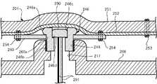
以下、図9を参照して、実施の形態4における貫通孔246cを有する凸状部品246について説明する。実施の形態4に係るロボット200は、実施の形態2で説明した貫通孔244cを有する凸状部品244の代わりに、凸状部品246を備える。なお、貫通孔を有さない凸状部品243の構成、及び係合板260の構成は、実施の形態2と同様であるため、説明を省略する。 Hereinafter, theconvex component 246 having the throughhole 246c according to the fourth embodiment will be described with reference to FIG. Therobot 200 according to the fourth embodiment includes a projectingpart 246 instead of the projectingpart 244 having the throughhole 244c described in the second embodiment. The configuration of theconvex part 243 having no through-hole and the configuration of theengagement plate 260 are the same as those in the second embodiment, so the description is omitted.

凸状部品246は、大径部である頭部246aと、小径部である軸部246bと、を備える。頭部246aは、係合板260に形成された嵌合孔260aの径よりも大きい径を有し、胴体部206の筐体から突出している。軸部246bは、嵌合孔260aの径とほぼ等しい径を有する円柱状をしており、胴体部206の筐体に挿入されている。 Theconvex part 246 has a largediameter head portion 246a and a smalldiameter shaft portion 246b. Thehead portion 246 a has a diameter larger than the diameter of thefitting hole 260 a formed in theengagement plate 260 and protrudes from the housing of thebody portion 206 . Theshaft portion 246b has a cylindrical shape with a diameter substantially equal to the diameter of thefitting hole 260a, and is inserted into the housing of thebody portion 206. As shown in FIG.

実施の形態4において、凸状部品246は、実施の形態2と同様に、本体部207の筐体とは一体で成形されておらず、別部品である。具体的に説明すると、凸状部品246は、いわゆる中空ねじであって、軸部246bの表面には、雄ねじが切られている。 In the fourth embodiment, similarly to the second embodiment, the projectingpart 246 is not integrally formed with the housing of themain body part 207, but is a separate part. Specifically, theconvex part 246 is a so-called hollow screw, and the surface of theshaft portion 246b is threaded with a male thread.

一方で、胴体部206には、凸状部品246が挿入される挿入穴216が設けられている。挿入穴216の表面には、軸部246bの雄ねじが螺合する雌ねじが切られている。頭部246aは、挿入穴216の径よりも大きい径を有する。凸状部品246は、挿入穴216に挿入されて、ドライバ等で締め付けられることにより、胴体部206の筐体に取り付けられる。 On the other hand, thebody portion 206 is provided with aninsertion hole 216 into which theconvex component 246 is inserted. The surface of theinsertion hole 216 is cut with a female thread into which the male thread of theshaft portion 246b is screwed.Head 246 a has a diameter larger than the diameter ofinsertion hole 216 . Theconvex part 246 is attached to the housing of thebody part 206 by being inserted into theinsertion hole 216 and tightened with a screwdriver or the like.

このような構成に加えて、凸状部品246は、貫通孔246cを更に有する。貫通孔246cは、凸状部品246の高さ方向に凸状部品246を貫通する孔である。貫通孔246cは、凸状部品246の頭部246aの上面から、軸部246bの底面まで貫通している。 In addition to such a configuration, theconvex part 246 further has a throughhole 246c. The through-hole 246c is a hole penetrating theconvex component 246 in the height direction of theconvex component 246 . The through-hole 246c penetrates from the top surface of thehead portion 246a of theconvex component 246 to the bottom surface of theshaft portion 246b.

また、胴体部206における挿入穴216の底部には、胴体部206の内部まで貫通する貫通孔217が設けられている。胴体部206の貫通孔217は、挿入穴216に挿入された凸状部品246の貫通孔246cの直下に位置している。 A throughhole 217 penetrating to the inside of thebody portion 206 is provided at the bottom of theinsertion hole 216 in thebody portion 206 . The throughhole 217 of thebody portion 206 is located directly below the throughhole 246 c of theconvex component 246 inserted into theinsertion hole 216 .

実施の形態4において、マイクロホン290は、凸状部品246に設けられた貫通孔246cの内部に配置されている。貫通孔246cは、マイクロホン290をその内部に収めることができるような大きさの径を有する。マイクロホン290は、貫通孔246cの内部において、胴体部206の外部に近い位置に配置されている。 In Embodiment 4, themicrophone 290 is arranged inside the throughhole 246 c provided in theconvex part 246 . The throughhole 246c has a diameter large enough to accommodate themicrophone 290 therein. Themicrophone 290 is arranged at a position close to the outside of thebody portion 206 inside the throughhole 246c.

より詳細には、貫通孔246cの内部における上方部の径は、下方部の径よりも若干大きくなっている。マイクロホン290は、貫通孔246cの内部における上方部と下方部との境界部に設けられた座面246dに設置されている。マイクロホン290に接続されたリード線291は、貫通孔246cの底部を通り、胴体部206の内部に設けられた制御ユニット292に導かれている。 More specifically, the diameter of the upper portion inside the throughhole 246c is slightly larger than the diameter of the lower portion. Themicrophone 290 is installed on aseat surface 246d provided at the boundary between the upper portion and the lower portion inside the throughhole 246c. Alead wire 291 connected to themicrophone 290 passes through the bottom of the throughhole 246 c and is led to acontrol unit 292 provided inside thebody 206 .

このように、実施の形態4では、マイクロホン290は、実施の形態2よりも胴体部206の外側に近い位置に設けられる。これにより、ロボット200の外部で発生した音は、より直接的にマイクロホン290に入力される。そのため、貫通孔246cを音が通過することによる音質の劣化(高音域の減衰)がほとんどなく、ユーザの音声、環境音等をより的確に認識し易くなる。更には、マイクロホン290が胴体部206の内部から遠い位置に設けられているため、本体部207の内部で発生したモータ等の動作音をマイクロホン290が拾うことを、より確実に抑えることができる。 Thus, in the fourth embodiment,microphone 290 is provided at a position closer to the outside ofbody section 206 than in the second embodiment. Accordingly, sounds generated outside therobot 200 are more directly input to themicrophone 290 . Therefore, there is almost no deterioration in sound quality (attenuation of high-pitched sounds) due to sound passing through the throughhole 246c, and the user's voice, environmental sounds, etc. can be more accurately recognized. Furthermore, since themicrophone 290 is provided at a position far from the inside of thebody portion 206, it is possible to more reliably suppress themicrophone 290 from picking up operating sounds generated inside thebody portion 207, such as the motor.

(変形例)
以上、実施の形態を説明したが、各実施の形態を組み合わせたり、各実施の形態を適宜、変形、省略したりすることが可能である。
(Modification)
Although the embodiments have been described above, it is possible to combine each embodiment, and to modify or omit each embodiment as appropriate.

例えば、上記実施の形態では、貫通孔242c,244c~246cを有する凸状部品242,244~246及びマイクロホン290は、胴体部206の前方部分の上側に設けられていた。しかしながら、凸状部品242,244~246及びマイクロホン290は、本体部207であれば、胴体部206の別の場所に設けられても良いし、頭部204に設けられても良い。例えば、頭部204及び胴体部206に設けられた複数の凸状部品241,243のうちのいずれかが、貫通孔242c,244c~246cを有する凸状部品242,244~246であって、貫通孔242c,244cに対向する位置又は貫通孔245c,246cの内部にマイクロホン290が設けられても良い。 For example, in the above embodiments,convex parts 242, 244-246 having throughholes 242c, 244c-246c andmicrophone 290 were provided on the upper front portion ofbody 206. FIG. However, theconvex parts 242 , 244 to 246 and themicrophone 290 may be provided elsewhere on thebody section 206 or may be provided on thehead section 204 as long as thebody section 207 is used. For example, one of the plurality ofconvex parts 241, 243 provided in thehead part 204 and thebody part 206 is aconvex part 242, 244 to 246 having throughholes 242c, 244c to 246c. Amicrophone 290 may be provided at a position facing theholes 242c and 244c or inside the throughholes 245c and 246c.

このように、マイクロホン290にリード線291を接続することができる場所であれば、配置の自由度は高い。例えば、凸状部品242,244~246及びマイクロホン290は、音の入力を受け付け易い場所等に自由に配置することができる。また、凸状部品242,244~246及びマイクロホン290を配置する場所として、音の入力を受け付け易い場所を選ぶ、外装201を本体部207に固定させると頭部204の動きに対する外装201の追従性を悪化させる位置を避ける等、ロボット200の性能を阻害しない配置が可能である。 In this way, the degree of freedom in placement is high as long as thelead wire 291 can be connected to themicrophone 290 . For example, theconvex parts 242, 244 to 246 and themicrophone 290 can be freely arranged in places where it is easy to receive sound input. In addition, as a place to arrange theconvex parts 242, 244 to 246 and themicrophone 290, a place where it is easy to receive sound input is selected. Arrangement that does not hinder the performance of therobot 200 is possible, such as avoiding a position that worsens the

また、係合板260及び凸状部品241~246の個数は、上記実施の形態で示したものに限らず、適用するロボットに応じて任意に決定することができる。例えば、大きなロボットであれば、より多くの係合板260及び凸状部品241~246を設置するようにしてもよい。 Further, the numbers of theengaging plate 260 and theconvex parts 241 to 246 are not limited to those shown in the above embodiments, and can be arbitrarily determined according to the robot to be applied. For example, for a large robot, moreengaging plates 260 and convex parts 241-246 may be installed.

上記実施の形態では、外装201の内側に設けられた係合部は、嵌合孔260aを有する係合板260であり、本体部207に設けられた被係合部は、嵌合孔260aに嵌合する凸状部品241~246であった。しかしながら、係合部と被係合部とで、凹凸を入れ替えても良い。言い換えると、外装201の内側に設けられた係合部が内側に向けて突出した凸状部品であり、本体部207に設けられた被係合部が嵌合孔を有する部品であっても良い。本体部207に設けられた被係合部が嵌合孔を有する部品であっても、被係合部は、本体部207の筐体と一体で設けられていても良いし、本体部207の筐体に対して着脱可能な部品であっても良い。このように、外装201の内側に設けられた係合部と本体部207に設けられた被係合部とのうちの一方が嵌合孔260aを有し、他方が凸状部品241~246であれば、外装201と本体部207とでどちらに凸状部品241~246が設けられていても良い。 In the above embodiment, the engaging portion provided inside theexterior 201 is theengaging plate 260 having thefitting hole 260a, and the engaged portion provided in thebody portion 207 is fitted into thefitting hole 260a. were mating convex parts 241-246. However, the unevenness may be exchanged between the engaging portion and the engaged portion. In other words, the engaging portion provided on the inside of the exterior 201 may be a convex component protruding inward, and the engaged portion provided on thebody portion 207 may be a component having a fitting hole. . Even if the engaged portion provided on themain body portion 207 is a part having a fitting hole, the engaged portion may be provided integrally with the housing of themain body portion 207, or may be provided integrally with the housing of themain body portion 207. It may be a component that can be attached to and detached from the housing. As described above, one of the engaging portion provided inside theexterior 201 and the engaged portion provided on thebody portion 207 has thefitting hole 260a, and the other is theconvex parts 241 to 246. If so, the projectingparts 241 to 246 may be provided on either the exterior 201 or themain body 207 .

上記実施の形態では、外装201に縫い付けられた係合部として、ポリアミド6(PA6)製のプレートを円形状に打ち抜いて成形した係合板260を用いたが、係合部の材質及び形状は任意に選択できる。例えば、係合部として、ポリカーボネード等の合成樹脂製のものを用いても良い。又は、係合部として、ポリエステル等の化学繊維の布を円形に切断したものを用いても良いし、綿、ウール等の天然繊維の布を用いても良いし、ゴム製のシート材を用いても良い。また、係合部の形状は、平板状であれば良く、三角板状、四角板状等の角形板状のものとしても良い。 In the above-described embodiment, the engagingplate 260 formed by punching a polyamide 6 (PA6) plate into a circular shape is used as the engaging portion sewn to theexterior 201. However, the material and shape of the engaging portion may vary. Can be selected arbitrarily. For example, the engaging portion may be made of synthetic resin such as polycarbonate. Alternatively, as the engaging portion, a cloth made of chemical fiber such as polyester cut into a circular shape may be used, a cloth made of natural fiber such as cotton or wool may be used, or a sheet material made of rubber may be used. can be Moreover, the shape of the engaging portion may be a flat plate shape, and may be a rectangular plate shape such as a triangular plate shape or a square plate shape.

上記実施の形態では、係合板260の外装201への縫い位置は、平行な2本のラインL1、L2上であると説明したが、他の縫い位置であってもよい。また、係合板260の外装201への取り付けは、ミシンによる縫い付けによるものだけに限定されない。例えば、係合板260を手で縫い付けてもよいし、嵌合孔260aの周囲に接着剤を塗布して係合板260を接着してもよい。 In the above-described embodiment, the stitching position of theengagement plate 260 to theexterior 201 is on the two parallel lines L1 and L2, but other stitching positions may be used. Moreover, the attachment of theengagement plate 260 to theexterior 201 is not limited to sewing with a sewing machine. For example, the engagingplate 260 may be sewn by hand, or theengaging plate 260 may be adhered by applying an adhesive around thefitting hole 260a.

上記実施の形態では、係合板260は、凸状部品241~246が嵌合する嵌合部として嵌合孔260aを有していた。しかしながら、嵌合部は、係合板260を貫通する孔であることに限らず、窪みであっても良い。そして、凸状部品241~246の頭部241a~246aが係合板260の窪みに嵌め込まれることにより、凸状部品241~246が係合板260に嵌合しても良い。この場合、貫通孔242c,244c~246cを有する凸状部品242,244~246が嵌め込まれる係合板260の窪みには、貫通孔242c,244c~246cの直上に、係合板260を貫通する貫通孔が設けられる。係合板260に設けられた貫通孔は、貫通孔242c,244cの直下又は貫通孔245c,246cの内部に配置されたマイクロホン290に集音するための集音孔(マイク孔)として機能する。 In the above embodiment, theengagement plate 260 has thefitting hole 260a as the fitting portion into which the convex parts 241-246 are fitted. However, the fitting portion is not limited to being a hole passing through theengaging plate 260, and may be a recess. The projectingparts 241 to 246 may be fitted to theengaging plate 260 by fitting theheads 241a to 246a of the projectingparts 241 to 246 into the depressions of theengaging plate 260. FIG. In this case, the depressions of theengaging plate 260 into which theconvex parts 242, 244 to 246 having the throughholes 242c, 244c to 246c are fitted have through holes penetrating theengaging plate 260 directly above the throughholes 242c, 244c to 246c. is provided. The through holes provided in theengaging plate 260 function as sound collecting holes (microphone holes) for collecting sound to themicrophones 290 arranged directly below the throughholes 242c and 244c or inside the throughholes 245c and 246c.

上記実施の形態では、頭部204が可動部であると説明した。しかしながら、可動部は、頭部204に限らず、手部、足部等であっても良い。外装201が手部、足部等の動きに追従して動くものであっても良い。また、本体部207が必ずしも可動部を有さなくても良い。この場合でも、ユーザがロボットを直接動かす際に外装201と本体部207との間の擦れ音が生じるため、擦れ音がマイクロホン290に入力されることを抑えることができる。 In the above embodiments, thehead 204 is described as the movable part. However, the movable part is not limited to thehead 204, and may be a hand part, a foot part, or the like. The exterior 201 may move following the movement of the hands, feet, or the like. Also, thebody portion 207 does not necessarily have to have a movable portion. Even in this case, when the user directly moves the robot, a rubbing sound is generated between the exterior 201 and themain body 207, so inputting the rubbing sound to themicrophone 290 can be suppressed.

上記実施の形態では、ロボット200は小動物を模したものであると説明したが、ロボット200が何を模したものとするのかは任意である。例えば、ロボット200は、サイといった大型の動物を模したものとしてもよい。また、上記実施の形態では、外装201及びマイクロホン290を備える電子機器として、ロボット200を例にとって説明した。しかしながら、電子機器は、ロボット以外のぬいぐるみのような玩具であってもよい。さらには、電子機器は、ロボット以外の機器であってよい。例えば、電子機器がノイズキャンセリング機能を有するヘッドフォンを衣服であるパーカーのフード部分に設けるような機器であれば、ノイズキャンセリングのために外部音を取得するマイクロホンが必要であり、当該マイクロホンはフード部分の布の表地と裏地の間に実装される可能性が高い。そのような場合に本開示を適用することができる。 In the above embodiment, therobot 200 is described as imitating a small animal, but therobot 200 may be imitating any object. For example,robot 200 may resemble a large animal such as a rhinoceros. Further, in the above-described embodiment, therobot 200 has been described as an example of an electronic device including theexterior 201 and themicrophone 290 . However, the electronic device may be a toy such as a stuffed toy other than a robot. Furthermore, the electronic device may be a device other than a robot. For example, if the electronic device has headphones with a noise canceling function attached to the hood of a hoodie that is clothing, a microphone that acquires external sound is required for noise cancellation, and the microphone is attached to the hood. It is likely to be implemented between the fabric face and lining of the part. In such cases, the present disclosure can be applied.

また、外装201は、本体部207の全てを覆う形態に限定されるものではなく、本体部207の一部を覆う形態であってもよい。また、外装201は小動物の毛皮を模したものであると説明したが、外装201を何にするのかは任意である。例えば、外装201を、ロボット200に取り付ける服を模したものとしてもよい。 Moreover, theexterior 201 is not limited to a form that covers the entiremain body 207 , and may cover a part of themain body 207 . Also, although theexterior 201 has been described as simulating the fur of a small animal, the exterior 201 may be made arbitrarily. For example, the exterior 201 may be made to look like clothes attached to therobot 200 .

上記実施の形態では、表地251と裏地252とは、糸253を用いて互いに縫い合わせられていると説明したが、他の方法により表地251と裏地252と一体化させてもよい。例えば、接着剤を用いて、表地251と裏地252とを接着してもよい。 In the above embodiment, theouter material 251 and thelining material 252 are sewn together using thethread 253, but theouter material 251 and thelining material 252 may be integrated by other methods. For example, an adhesive may be used to bond theouter material 251 and thelining material 252 together.

本発明は、本発明の広義の精神と範囲とを逸脱することなく、様々な実施の形態及び変形が可能とされるものである。また、前述した実施の形態は、この発明を説明するためのものであり、本発明の範囲を限定するものではない。すなわち、本発明の範囲は、実施の形態ではなく、特許請求の範囲によって示される。そして、特許請求の範囲内及びそれと同等の発明の意義の範囲内で施される様々な変形が、この発明の範囲内とみなされる。以下に、本願出願の当初の特許請求の範囲に記載された発明を付記する。 The present invention is capable of various embodiments and modifications without departing from the broader spirit and scope of the invention. Moreover, the embodiments described above are for explaining the present invention, and do not limit the scope of the present invention. That is, the scope of the present invention is indicated by the claims rather than the embodiments. Various modifications made within the scope of the claims and within the meaning of equivalent inventions are considered to be within the scope of the present invention. The invention described in the original claims of the present application is appended below.

(付記1)
外装と、
前記外装に覆われる本体部と、
前記外装の内側に設けられた係合部と、
前記本体部に設けられ、前記係合部と係合することにより前記外装を前記本体部に係止する被係合部と、
マイクロホンと、を備え、
前記係合部と前記被係合部とのうちの一方は、嵌合部を有し、
前記係合部と前記被係合部とのうちの他方は、前記嵌合部に嵌合する凸状部品であり、
前記凸状部品は、前記凸状部品の高さ方向に前記凸状部品を貫通する貫通孔を有し、
前記マイクロホンは、前記本体部の内部において前記貫通孔に対向する位置に配置された、
電子機器。
(付記2)
外装と、
前記外装に覆われる本体部と、
前記外装の内側に設けられた係合部と、
前記本体部に設けられ、前記係合部と係合することにより前記外装を前記本体部に係止する被係合部と、
マイクロホンと、を備え、
前記係合部と前記被係合部とのうちの一方は、嵌合部を有し、
前記係合部と前記被係合部とのうちの他方は、前記嵌合部に嵌合する凸状部品であり、
前記凸状部品は、前記凸状部品の高さ方向に前記凸状部品を貫通する貫通孔を有し、
前記マイクロホンは、前記貫通孔の内部に配置された、
電子機器。
(付記3)
前記本体部は、可動部を有し、
前記外装は、前記可動部の動きに追従して動く、
付記1又は2に記載の電子機器。
(付記4)
前記被係合部は、前記本体部の筐体と一体で設けられた、
付記1から3のいずれか1つに記載の電子機器。
(付記5)
前記被係合部は、前記本体部の筐体に対して着脱可能な部品である、
付記1から4のいずれか1つに記載の電子機器。
(付記6)
前記係合部は、前記嵌合部を有し、
前記被係合部は、前記凸状部品である、
付記1から5のいずれか1つに記載の電子機器。
(付記7)
前記係合部は、前記凸状部品であり、
前記被係合部は、前記嵌合部を有する、
付記1から5のいずれか1つに記載の電子機器。
(Appendix 1)
Exterior and
a main body covered with the exterior;
an engaging portion provided inside the exterior;
a to-be-engaged portion provided on the main body portion for locking the exterior to the main body portion by engaging with the engaging portion;
a microphone;
one of the engaging portion and the engaged portion has a fitting portion;
the other of the engaging portion and the engaged portion is a convex component that fits into the fitting portion;
The convex part has a through hole penetrating the convex part in the height direction of the convex part,
The microphone is arranged inside the main body at a position facing the through hole,
Electronics.
(Appendix 2)
Exterior and
a main body covered with the exterior;
an engaging portion provided inside the exterior;
a to-be-engaged portion provided on the main body portion for locking the exterior to the main body portion by engaging with the engaging portion;
a microphone;
one of the engaging portion and the engaged portion has a fitting portion;
the other of the engaging portion and the engaged portion is a convex component that fits into the fitting portion;
The convex part has a through hole penetrating the convex part in the height direction of the convex part,
The microphone is arranged inside the through hole,
Electronics.
(Appendix 3)
The body portion has a movable portion,
The exterior moves following the movement of the movable part,
The electronic device according to appendix 1 or 2.
(Appendix 4)
The engaged portion is provided integrally with the housing of the main body,
The electronic device according to any one of Appendices 1 to 3.
(Appendix 5)
The engaged portion is a part that can be attached to and detached from the housing of the main body,
5. The electronic device according to any one of Appendices 1 to 4.
(Appendix 6)
The engaging portion has the fitting portion,
The engaged portion is the convex component,
6. The electronic device according to any one of Appendices 1 to 5.
(Appendix 7)
The engaging portion is the convex component,
The engaged portion has the fitting portion,
6. The electronic device according to any one of Appendices 1 to 5.

101…載置面、102,103…軸、200…ロボット、201…外装、202…装飾部品、203…毛、204…頭部、205…連結部、206…胴体部、207…本体部、208…線ファスナ、208a…スライダ、213,214,216…挿入穴、215,217…貫通孔、221…ひねりモータ、222…上下モータ、241~246…凸状部品、241a~246a…頭部、241b~246b…軸部、242c,244c~246c…貫通孔、245d,246d…座面、251…表地、252…裏地、253,254…糸、260…係合板、260a…嵌合孔、290…マイクロホン、291…リード線、292…制御ユニット、L1,L2…ラインDESCRIPTION OFSYMBOLS 101... Mountingsurface 102, 103...Axis 200...Robot 201...Exterior 202...Decorative part 203...Hair 204...Head 205...Connection part 206...Body part 207...Body part 208Linefastener 208a Slider 213, 214, 216Insertion hole 215, 217 Throughhole 221Twist motor 222Vertical motor 241 to 246Convex part 241a to 246aHead 241b 246b ...Shaft 242c, 244c to 246c ... Throughhole 245d, 246d ...Seat surface 251 ...Outer material 252 ... Lining 253, 254 ...Thread 260 ...Engagement plate 260a ...Fitting hole 290 ... Microphone , 291... lead wire, 292... control unit, L1, L2... line

Claims (7)

Translated fromJapanese
外装と、
前記外装に覆われる本体部と、
前記外装の内側に設けられた係合部と、
前記本体部に設けられ、前記係合部と係合することにより前記外装を前記本体部に係止する被係合部と、
マイクロホンと、を備え、
前記係合部と前記被係合部とのうちの一方は、嵌合部を有し、
前記係合部と前記被係合部とのうちの他方は、前記嵌合部に嵌合する凸状部品であり、
前記凸状部品は、前記凸状部品の高さ方向に前記凸状部品を貫通する貫通孔を有し、
前記マイクロホンは、前記本体部の内部において前記貫通孔に対向する位置に配置された、
電子機器。
Exterior and
a main body covered with the exterior;
an engaging portion provided inside the exterior;
a to-be-engaged portion provided on the main body portion for locking the exterior to the main body portion by engaging with the engaging portion;
a microphone;
one of the engaging portion and the engaged portion has a fitting portion;
the other of the engaging portion and the engaged portion is a convex component that fits into the fitting portion;
The convex part has a through hole penetrating the convex part in the height direction of the convex part,
The microphone is arranged inside the main body at a position facing the through hole,
Electronics.
外装と、
前記外装に覆われる本体部と、
前記外装の内側に設けられた係合部と、
前記本体部に設けられ、前記係合部と係合することにより前記外装を前記本体部に係止する被係合部と、
マイクロホンと、を備え、
前記係合部と前記被係合部とのうちの一方は、嵌合部を有し、
前記係合部と前記被係合部とのうちの他方は、前記嵌合部に嵌合する凸状部品であり、
前記凸状部品は、前記凸状部品の高さ方向に前記凸状部品を貫通する貫通孔を有し、
前記マイクロホンは、前記貫通孔の内部に配置された、
電子機器。
Exterior and
a main body covered with the exterior;
an engaging portion provided inside the exterior;
a to-be-engaged portion provided on the main body portion for locking the exterior to the main body portion by engaging with the engaging portion;
a microphone;
one of the engaging portion and the engaged portion has a fitting portion;
the other of the engaging portion and the engaged portion is a convex component that fits into the fitting portion;
The convex part has a through hole penetrating the convex part in the height direction of the convex part,
The microphone is arranged inside the through hole,
Electronics.
前記本体部は、可動部を有し、
前記外装は、前記可動部の動きに追従して動く、
請求項1又は2に記載の電子機器。
The body portion has a movable portion,
The exterior moves following the movement of the movable part,
The electronic device according to claim 1 or 2.
前記被係合部は、前記本体部の筐体と一体で設けられた、
請求項1から3のいずれか1項に記載の電子機器。
The engaged portion is provided integrally with the housing of the main body,
The electronic device according to any one of claims 1 to 3.
前記被係合部は、前記本体部の筐体に対して着脱可能な部品である、
請求項1から4のいずれか1項に記載の電子機器。
The engaged portion is a part that can be attached to and detached from the housing of the main body,
The electronic device according to any one of claims 1 to 4.
前記係合部は、前記嵌合部を有し、
前記被係合部は、前記凸状部品である、
請求項1から5のいずれか1項に記載の電子機器。
The engaging portion has the fitting portion,
The engaged portion is the convex component,
The electronic device according to any one of claims 1 to 5.
前記係合部は、前記凸状部品であり、
前記被係合部は、前記嵌合部を有する、
請求項1から5のいずれか1項に記載の電子機器。
The engaging portion is the convex component,
The engaged portion has the fitting portion,
The electronic device according to any one of claims 1 to 5.
JP2021051547A2021-03-252021-03-25 ElectronicsActiveJP7188485B2 (en)

Priority Applications (1)

Application NumberPriority DateFiling DateTitle
JP2021051547AJP7188485B2 (en)2021-03-252021-03-25 Electronics

Applications Claiming Priority (1)

Application NumberPriority DateFiling DateTitle
JP2021051547AJP7188485B2 (en)2021-03-252021-03-25 Electronics

Publications (2)

Publication NumberPublication Date
JP2022149407Atrue JP2022149407A (en)2022-10-06
JP7188485B2 JP7188485B2 (en)2022-12-13

Family

ID=83463168

Family Applications (1)

Application NumberTitlePriority DateFiling Date
JP2021051547AActiveJP7188485B2 (en)2021-03-252021-03-25 Electronics

Country Status (1)

CountryLink
JP (1)JP7188485B2 (en)

Citations (5)

* Cited by examiner, † Cited by third party
Publication numberPriority datePublication dateAssigneeTitle
JP3056215U (en)*1998-07-271999-02-12イズミ電子株式会社 Hands-free communication device
JP2001191276A (en)*1999-10-292001-07-17Sony CorpRobot system, robot device and exterior thereof
US20140329433A1 (en)*2013-05-062014-11-06Israel CarreroToy Stuffed Animal with Remote Video and Audio Capability
JP2018061123A (en)*2016-10-042018-04-12トヨタ自動車株式会社Voice recognition device
JP2020156607A (en)*2019-03-252020-10-01カシオ計算機株式会社Control device, robot, control method, and program

Patent Citations (5)

* Cited by examiner, † Cited by third party
Publication numberPriority datePublication dateAssigneeTitle
JP3056215U (en)*1998-07-271999-02-12イズミ電子株式会社 Hands-free communication device
JP2001191276A (en)*1999-10-292001-07-17Sony CorpRobot system, robot device and exterior thereof
US20140329433A1 (en)*2013-05-062014-11-06Israel CarreroToy Stuffed Animal with Remote Video and Audio Capability
JP2018061123A (en)*2016-10-042018-04-12トヨタ自動車株式会社Voice recognition device
JP2020156607A (en)*2019-03-252020-10-01カシオ計算機株式会社Control device, robot, control method, and program

Also Published As

Publication numberPublication date
JP7188485B2 (en)2022-12-13

Similar Documents

PublicationPublication DateTitle
US11534682B2 (en)Input device
US7677353B2 (en)Noise suppression structure
JP4416027B2 (en) Ultrasonic beauty equipment
US20190141434A1 (en)Speaker device
KR20140071740A (en)Robot cleaner
CN115052222A (en)Bone conduction earphone head and bone conduction earphone
US20180008902A1 (en)Toy reactive to a signal
JP7188485B2 (en) Electronics
US12064870B2 (en)Soundproofing device, robot apparatus, method for controlling robot apparatus, and program
CN218041711U (en)Bone conduction earphone head and bone conduction earphone
JP3103674U (en) Touch-type indirect conduction vibration type microphone
CN111152239B (en) A robot
CN222561931U (en)Wearable device
JP2001309473A (en)Waterproof vibration microphone
JP6850521B2 (en) Communication units, communication devices and programs
JPWO2008029514A1 (en) Vibration pickup microphone
JP6197018B2 (en) Plush Doll
CN111601202A (en)Wearing equipment, suit that has this wearing equipment
HK1249874A1 (en)Stuffed toy
US20030031325A1 (en)Electrolarynx with an improved diaphragm
CN221283283U (en)Sound production device and cleaning equipment
JP7001851B2 (en) Cap device, connector cap mounting structure and electronic equipment
KR200270920Y1 (en)Doll having mp3 player
JP7255620B2 (en) Device
JP3068751U (en) Drive for toys

Legal Events

DateCodeTitleDescription
A621Written request for application examination

Free format text:JAPANESE INTERMEDIATE CODE: A621

Effective date:20210527

A131Notification of reasons for refusal

Free format text:JAPANESE INTERMEDIATE CODE: A131

Effective date:20220628

A521Request for written amendment filed

Free format text:JAPANESE INTERMEDIATE CODE: A523

Effective date:20220810

TRDDDecision of grant or rejection written
A01Written decision to grant a patent or to grant a registration (utility model)

Free format text:JAPANESE INTERMEDIATE CODE: A01

Effective date:20221101

A61First payment of annual fees (during grant procedure)

Free format text:JAPANESE INTERMEDIATE CODE: A61

Effective date:20221114

R150Certificate of patent or registration of utility model

Ref document number:7188485

Country of ref document:JP

Free format text:JAPANESE INTERMEDIATE CODE: R150


[8]ページ先頭

©2009-2025 Movatter.jp